JP2014123893A - Color conversion processing method, color conversion processing device, and program - Google Patents
Color conversion processing method, color conversion processing device, and programDownload PDFInfo
- Publication number
- JP2014123893A JP2014123893AJP2012279679AJP2012279679AJP2014123893AJP 2014123893 AJP2014123893 AJP 2014123893AJP 2012279679 AJP2012279679 AJP 2012279679AJP 2012279679 AJP2012279679 AJP 2012279679AJP 2014123893 AJP2014123893 AJP 2014123893A
- Authority
- JP
- Japan
- Prior art keywords
- color
- color material
- special
- basic
- hue
- Prior art date
- Legal status (The legal status is an assumption and is not a legal conclusion. Google has not performed a legal analysis and makes no representation as to the accuracy of the status listed.)
- Granted
Links
Images


Landscapes
- Image Processing (AREA)
- Facsimile Image Signal Circuits (AREA)
- Color Image Communication Systems (AREA)
Abstract
Translated fromJapaneseDescription
Translated fromJapanese本発明は、CMYK信号を、特色色材を含むN色信号へ色変換する色変換処理方法、色変換処理装置およびプログラムに関する。 The present invention relates to a color conversion processing method, a color conversion processing device, and a program for color-converting a CMYK signal into an N color signal including a special color material.
カラープリンティング技術において、プロセス色材(CMYK)を用いて印刷するプリンタが一般的に知られているが、新たにレッド(R)、グリーン(G)、などの特色色材(トナー、インク)を加えて印刷する多色プリンタがある。多色プリンタでは特色色材を加えることで、色再現域が広がるが、多色印刷するためには、RGBやCMYKデバイス信号を、特色を含むN色デバイス信号へ変換する必要があり、その変換方法に関する技術がある(例えば、特許文献1を参照)。 In color printing technology, printers that print using process color materials (CMYK) are generally known, but new special color materials (toner, ink) such as red (R) and green (G) are newly added. In addition, there are multicolor printers that print. In multicolor printers, the color reproduction range is expanded by adding special color materials. However, in order to perform multicolor printing, it is necessary to convert RGB and CMYK device signals to N color device signals including special colors. There is a technique related to the method (see, for example, Patent Document 1).
CMYKデバイス信号を、特色色材を含むN色デバイス信号に色変換する際には、N色で再現可能な色域を十分に活用することが望ましい。従来、特色色相において、最高彩度点より高明度色域と低明度色域に分けて、まず高明度側を特色単色で印刷した場合と、特色と色相的に隣接するプロセス色材2色で印刷した場合の彩度を比較して、その結果に応じて低明度側の色材構成を決定している。 When color-converting a CMYK device signal into an N-color device signal including a special color material, it is desirable to fully utilize a color gamut that can be reproduced with N colors. Conventionally, in the special color hue, it is divided into a high lightness color gamut and a low lightness color gamut from the highest saturation point. First, the high lightness side is printed with a single special color, and two process colors adjacent to the special color in hue. The saturation at the time of printing is compared, and the color material configuration on the low brightness side is determined according to the result.
しかし、従来の技術では、色相毎に高明度側での彩度の比較を行い、その比較結果に応じて、色材構成を決定しているので、隣接色相間で色材構成が急激に変化する場合がある。そのため、色相間にわたる連続階調間で著しい階調性の低下が発生し、画質に悪影響を及ぼすという問題があった。また、高明度側を特色色材のみで印刷した方が高彩度であると判定された場合、低明度側では特色色材とその特色と色相的に隣接するプロセス色材を混色するような色材構成を考慮していないので、低明度色域を十分に活用できていないという問題があった。 However, in the conventional technology, the saturation on the high brightness side is compared for each hue, and the color material composition is determined according to the comparison result, so the color material composition changes rapidly between adjacent hues. There is a case. For this reason, there is a problem that a significant drop in gradation occurs between continuous gradations across hues, which adversely affects image quality. Also, if it is determined that the high brightness side is printed with only the special color material, it is determined that the color saturation is higher. On the low brightness side, the color material that mixes the special color material and the process color material that is adjacent to the special color in hue. Since the configuration is not taken into account, there is a problem that the low brightness color gamut cannot be fully utilized.
本発明は上記した課題に鑑みてなされたもので、
本発明の目的は、CMYKデバイス信号を、特色色材を含むN色デバイス信号へ色変換する際に、階調性の低下を抑制すると共に、N色で再現可能な色域を十分に活用するような色変換を実現する色変換処理方法、色変換処理装置およびプログラムを提供することにある。The present invention has been made in view of the above problems,
An object of the present invention is to suppress deterioration in gradation and to fully utilize a color gamut reproducible with N colors when color-converting a CMYK device signal into an N-color device signal including a special color material. Another object of the present invention is to provide a color conversion processing method, a color conversion processing device, and a program for realizing such color conversion.
本発明は、第1のCMY基本色の色材信号(c、m、y)に基づいて、前記CMY基本色と基本色の中間色相の色を有する特色色材とを含む第2の色材信号(C、M、Y、O、G)に変換する色変換処理方法であって、前記第2の色材信号のうち、各色材単色での最高彩度となる色の情報と、前記第2の色材信号のうち、特色色材とその特色と色相的に隣接する基本色色材とを混色して最高彩度となる色の情報と、特色色材と色相的に隣接する基本色色材2色を混色して最高彩度となる色に対して、前記特色色材とその特色と色相的に隣接する基本色色材のうちの2色を混色して同色相となる色の情報、のうち少なくとも1つの色の情報を取得するステップと、前記取得した色の情報をもとに、前記第1の色材信号の色空間の最高彩度の辺上に前記第2の色材信号を色相順に割り付けるステップと、前記割り付けられた色材信号値の点と、前記第1の色材信号の色空間において白色に相当する点と、黒色に相当する点とを結び、前記第1の色材信号の色空間を複数の四面体に分割するステップと、前記分割された各四面体の頂点における第1の色材信号値と、それに対応する第2の色材信号値との関係をもとに、前記第1の色材信号を前記第2の色材信号へ変換するための色変換LUTを作成するステップを備えることを最も主要な特徴とする。 The present invention provides a second color material including the CMY basic color and a special color material having an intermediate hue between the basic color and the color material signal (c, m, y) of the first CMY basic color. A color conversion processing method for converting into a signal (C, M, Y, O, G), wherein the second color material signal includes information on a color having the highest saturation in each color material, and the first color material signal. Of the two color material signals, the special color material and the basic color material that is adjacent to the special color in hue are mixed, and the color information that gives the highest saturation, and the basic color material that is adjacent to the special color material in hue. Information on the color that has the same hue by mixing two colors of the special color material and the basic color material that is huewise adjacent to the special color material with respect to the color that has the highest saturation by mixing the two colors. Acquiring at least one color information, and based on the acquired color information, on the side of the highest saturation of the color space of the first color material signal A step of assigning the second color material signal in order of hue; a point of the assigned color material signal value; a point corresponding to white in a color space of the first color material signal; and a point corresponding to black. And dividing the color space of the first color material signal into a plurality of tetrahedrons, a first color material signal value at the vertex of each of the divided tetrahedrons, and a second color corresponding thereto The most important feature is that it includes a step of creating a color conversion LUT for converting the first color material signal into the second color material signal based on the relationship with the material signal value.
本発明によれば、特色色材を含むN色信号への色変換を行う際に、特色色相において、隣接色相間で階調性の低下を抑制することができる。また、最高彩度点よりも低明度側の色域でも、色再現範囲を十分に活用することができる。 According to the present invention, when performing color conversion to an N color signal including a special color material, it is possible to suppress a decrease in gradation between adjacent hues in a special color hue. In addition, the color reproduction range can be fully utilized even in the color gamut on the lower brightness side than the maximum saturation point.
以下、発明の実施の形態について図面により詳細に説明する。本発明は、特色色材を含むN色信号への色変換処理を行う際に、特色色相において、プロセス色材と特色色材の混色で最高彩度となる色を、入力cmyk空間の最高彩度に相当する辺上に色相順に配置して、隣接する点(色)間の色差に応じて割り付ける。 Hereinafter, embodiments of the present invention will be described in detail with reference to the drawings. In the present invention, when color conversion processing to an N color signal including a special color material is performed, the color having the highest saturation in the special color hue by the color mixture of the process color material and the special color material is set to the highest color in the input cmyk space. They are arranged in order of hue on the side corresponding to the degree, and assigned according to the color difference between adjacent points (colors).
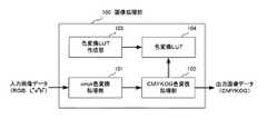
図1は、本発明の実施例1の色変換LUT作成方法で作成した色変換LUTを用いた色変換処理装置の構成を示す。画像処理部100に入力画像として、RGBや独立色空間CIE L*a*b*などで構成されるデータが入力されると、cmyk色変換処理部101は、入力画像データをCMYK画像データに変換し、CMYKOG色変換処理部102へ渡す。ここで、CMYK画像データとは、出力するプリンタをCMYKプリンタとみなし生成された画像データのことで、すなわち、cmyk色変換処理部101には、CMYK変換に対応した一般的な色変換方法を利用できる構成が採用される。 FIG. 1 shows the configuration of a color conversion processing apparatus using a color conversion LUT created by the color conversion LUT creation method of
また、CMYKOGはそれぞれ、シアン(C)、マゼンタ(M)、イエロー(Y)、ブラック(K)、およびオレンジ(O)、グリーン(G)の紙に印字する際に使用する色材量を決定するための色材信号であり、各色256階調で、各色材信号は0〜255の範囲とする。以下では、CMYK基本色をプロセス色材、CMY基本色の中間色相の色を有するO、Gなどの色材を特色色材と呼ぶこととする。 CMYKOG determines the amount of color material used when printing on cyan (C), magenta (M), yellow (Y), black (K), orange (O), and green (G) paper, respectively. The color material signal is a range of 0 to 255 for each color of 256 gradations. Hereinafter, CMYK basic colors are referred to as process color materials, and O, G, and other color materials having intermediate colors of CMY basic colors are referred to as special color materials.
CMYKOG色変換処理部102は、cmyk色変換処理部101によって変換されたcmyk画像データを受け取り、色変換LUT104を参照して、CMYKOGの画像信号へと変換する。なお、色変換LUT104は予め作成しておき、プリンタ内部のハードディスクあるいは、プリンタ外部の記録装置等に保存しておき、変換処理する際に参照できるようにしておくとよい。そして、CMYKOGの画像信号が出力画像データとして生成され、その画像データをもとに、画像形成装置で画像が印刷される。CMYKOG色変換処理部102で行われる一連の処理の詳細は、図7、図8で説明する。 The CMYKOG color
ただし、実際に印刷する際には、CMYKOGの画像データに変換した後に、色材信号総量が予め設定された制限値を超えていないかどうかを判定し、超えているようであれば、総量規制値を超えないように各色材信号を修正する。また、修正された色材信号に対して、階調処理が施される。これは、画像データは256階調数を有するのに対して、画像形成装置では、各画素に対してドットを形成するか否か、あるいは数種のドットサイズを制御することでしか階調性を表現できない。そのため、CMYKOGの画像データを誤差拡散やディザ等の方法により、画素毎のドット形成を表す記録データにする。 However, when actually printing, after converting to CMYKOG image data, it is determined whether the total amount of color material signals does not exceed a preset limit value. Each color material signal is corrected so as not to exceed the value. Further, gradation processing is performed on the corrected color material signal. This is because the image data has 256 gradations, but the image forming apparatus can only perform gradation by controlling whether or not to form dots for each pixel, or by controlling several dot sizes. Cannot be expressed. Therefore, the CMYKOG image data is converted into recording data representing dot formation for each pixel by a method such as error diffusion or dithering.
色変換LUT作成部103は、プロセス色材単色、ならびに、特色色材とその特色と色相的に隣接するプロセス色材とを混色した色の情報をもとに、cmy入力色空間上にCMYOGの色材信号を割り付ける。そして、割り付けた点から複数の四面体に分割し、各四面体の頂点データ群と、割り付けた入力cmyと出力CMYOGの色材信号の対応関係から算出する色変換行列のデータ群とを、結合してそれを色変換LUTとして作成する。色変換LUT作成部103で行われる一連の処理の詳細は、図2で説明する。 The color conversion
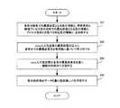
図2は、本発明の実施例1に係る、色変換LUT作成方法の処理フローチャートを示す。図2を参照して、本発明の色変換LUT作成方法を説明する。ステップ201において、各色材単色での最高彩度となる色の情報、ならびに、特色色材と隣接プロセス色材混色での最高彩度となる色の情報、ならびに、プロセス色材2次色ベタ対応色となる色の情報を取得する。なお、色の情報とは色材信号値ならびにデバイス独立信号値(L*a*b*値)を指すものとする。 FIG. 2 is a process flowchart of the color conversion LUT creation method according to the first embodiment of the present invention. The color conversion LUT creation method of the present invention will be described with reference to FIG. In
まず、各色材単色で色材信号値を0〜255まで滑らかに変化させた時の、最高彩度点となる色の情報を取得する。次に、特色色材と隣接プロセス色材のうちの1色との混色で、各色材信号値を0〜255まで等量で滑らかに変化させた時の、最高彩度点となる色の情報を取得する。次に、隣接プロセス色材2色の混色で最高彩度点となる色の情報を前記と同様にして取得する。そして、特色色材と隣接プロセス色材のうちの2色の混色で、前記隣接プロセス色材2色の混色の最高彩度点の色と同色相である色の情報を前記と同様にして取得する。 First, information on the color that becomes the highest saturation point when the color material signal value is smoothly changed from 0 to 255 for each color material is obtained. Next, information on the color that becomes the maximum saturation point when each color material signal value is smoothly changed in an equal amount from 0 to 255 in the mixed color of the special color material and one of the adjacent process color materials. To get. Next, the information of the color that becomes the maximum saturation point in the mixed color of the two adjacent process color materials is obtained in the same manner as described above. Then, in the same manner as described above, information on the color having the same hue as the color of the highest saturation point of the mixed color of the two adjacent process color materials is obtained by mixing the two colors of the special color material and the adjacent process color material. To do.
なお、以下では、この色をプロセス色材2次色ベタ対応色と呼ぶことにする。例えば、特色色材をグリーンとする場合には、まず、隣接プロセス色材であるシアンとイエローの混色で最高彩度となる色の情報を取得しておき、次に、グリーン、シアン、イエローのうちの2色の混色で、シアンとイエローの混色の最高彩度の色の色相と同等となる色の情報を取得することになる。なお、ここでいう最高彩度となる色の情報とは、色材信号値を0〜255まで滑らかに変化させた時の、最高彩度点の色材信号値ならびに、それに対応するデバイス独立信号値(CIE L*a*b*、XYZ等)を指す。 Hereinafter, this color is referred to as a process color material secondary color solid corresponding color. For example, when the special color material is green, first, information on the color having the highest saturation in the mixed color of cyan and yellow, which are adjacent process color materials, is obtained, and then, green, cyan, and yellow are obtained. Of these two colors, color information equivalent to the hue of the highest saturation color of the mixed color of cyan and yellow is acquired. Note that the color information with the highest saturation here is the color material signal value at the highest saturation point when the color material signal value is smoothly changed from 0 to 255, and the device independent signal corresponding thereto. Value (CIE L * a * b *, XYZ, etc.).
色情報は、プロセス色材で構成される色材信号と、それに対応して出力されたカラーパッチの測色値との関係から色予測モデルを構築し、色予測を行うことで得ることができる。或いは、色材信号に基づいてカラーパッチを出力し、それを測色することで色の情報を得ることができる。ここで、最高彩度の色の色材信号値が255でない場合には、その点を各色材使用量の上限として、色材信号の範囲を0〜上限までとして、CIE L*a*b*距離均等によりγ補正LUTを作成しておく。作成したγ補正LUTは、色変換後の色材信号値から、プリンタで出力する際に使用される出力信号値を決定する際に参照される。 The color information can be obtained by constructing a color prediction model from the relationship between the color material signal composed of the process color material and the colorimetric value of the color patch output corresponding thereto, and performing color prediction. . Alternatively, color information can be obtained by outputting a color patch based on the color material signal and measuring the color patch. Here, when the color material signal value of the color with the highest saturation is not 255, the point is set as the upper limit of each color material usage amount, and the range of the color material signal is set from 0 to the upper limit. CIE L * a * b * A γ correction LUT is created by equal distance. The created γ correction LUT is referred to when determining an output signal value to be used for output by the printer from the color material signal value after color conversion.
次に、ステップ202では、cmy入力色空間(色立方体空間)の最高彩度の辺上に上記ステップ201で取得した各色最高彩度の色をL*a*b*値に基づいて色相順に配置する。さらに、最高彩度の辺上に配置された各色最高彩度の色の点の隣接点間の色情報に基づいて、割り付けを行う。cmy入力色空間上への色材信号値の割り付け方法については、図3で詳細に説明する。 Next, in
次に、ステップ203では、ステップ202でcmy入力色空間に割り付けられた各色材最高彩度の色の点を基に複数の四面体に分割する。cmy入力色空間の四面体分割方法については、図4、図5で詳細に説明する。 Next, in
次に、ステップ204では、ステップ203で分割された各四面体頂点データを基に色変換LUTを作成する。色変換LUTの詳細については、図6で詳細に説明する。 Next, in
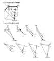
図3は、cmy入力色空間上への色材信号値の割り付け方法の処理フローチャートを示す。図4は、cmy入力色により規定される色立方体空間上への色材信号値の割り付けの具体例を説明する図である。 FIG. 3 shows a processing flowchart of a method for assigning color material signal values onto the cmy input color space. FIG. 4 is a diagram for explaining a specific example of allocation of color material signal values on the color cube space defined by the cmy input color.
図3、図4を参照して、cmy入力色空間上への色材信号値の割り付け方法を説明する。ステップ301では、cmy入力色空間上に白、および黒に対応する点を割り付ける。図4(A)は、k=0として、入力色空間をcmyの3次元色空間に簡略した図である。そのため、図示した色立方体の表面は入力色空間最外郭の一部のみを示しており、以下では、C−Y色相の割り付け方法について説明する。なお、入力信号CMYKと出力信号CMYKOGとを区別するために、入力信号CMYKを小文字のcmyk信号と表記する。cmy入力色空間において、(c,m,y)=(0,0,0)の点は白、(c,m,y)=(255,255,255)の点は黒である。よって、cmy入力色空間の白に相当する点が、出力信号値でも白となるように、(C,M,Y,K,O,G)=(0,0,0,0,0,0)を割り付ける。また、cmy入力色空間の黒に相当する点には、入力信号値をそのまま出力するように、(C,M,Y,K,O,G)=(255,255,255,0,0,0)を割り付ける。ここで、白と黒に対応する点を結ぶ直線は、無彩色の集まりであるので、以下では、この直線を無彩色軸と呼ぶ。また、cmy入力色空間において、白および黒に相当する点を通らない立方体の各辺は、各色相の最高彩度点に対応する(以下では、これらの辺を最高彩度の辺と呼ぶ)。 With reference to FIGS. 3 and 4, a method for assigning color material signal values to the cmy input color space will be described. In
次に、ステップ302では、cmy入力色空間上にプロセス色材単色ベタに対応する点を割り付ける。なお、ここでいうベタとは、最高彩度である色を指すものとする。図4(B)は、cmy入力色空間の最高彩度の辺上にプロセス色材単色ベタの色を割り付けた図である。cmy入力色空間のc、m、y各軸ではcmy入力信号と出力信号のCMYが同じになるようにするため、入力色空間のc、m、y各軸255の点にプロセス色材単色ベタの点を割り付ける。こうすることで、単色色信号が入力された場合には、出力色信号でも単色となることが保証される。 Next, in
次に、ステップ303では、cmy入力色空間上にプロセス色材2次色ベタ対応色の点を割り付ける。図4(C)は、cmy入力色空間の最高彩度の辺上に隣接プロセス色材2次色ベタに対応する色を割り付けた図である。cmy入力色空間の(c,m,y)=(255,0,255)の点に、隣接プロセス色材による2次色ベタと同色相で最高彩度である色を割り付ける。プロセス色材2次色ベタ対応色は、予め、隣接プロセス色材2次色混色ベタと、特色色材とその特色と色相的に隣接するプロセス色1色とを組み合わせた混色との色情報を基に決定しておけば良い。 Next, in
次に、ステップ304では、特色色材単色ベタ、ならびに、特色色材と隣接プロセス色材による2次色ベタにそれぞれ対応する点を、cmy入力色空間の最高彩度の辺上に色相順に配置する。図4(D)は、cmy入力色空間の最高彩度の辺上に特色色材単色ベタ(G)、特色色材とその特色と色相的に隣接するプロセス色材による2次色ベタの色(Y+G、G+C)を色相順に配置した図である。ステップ303の時点では、プロセス色材単色ベタ、プロセス色材2次色ベタ対応色の色相角が既知であるため、その色相角を参照して、特色色材単色ベタならびに、特色色材と隣接プロセス色材による2次色ベタの色を色相順に配置する。 Next, in
次に、ステップ305では、ステップ304で色相順に配置した各点を隣接間色差に応じて割り付ける。図4(E)は、各色材ベタ点を隣接間色差に基づいて、割り付け位置を決定した図である。ステップ304までの一連の処理を終えて、プロセス色材単色ベタ、特色色材単色ベタ、特色色材と隣接プロセス色材により2次色ベタ、プロセス色材2次色ベタ対応色が色相順に配置された。次に、これらの点を色相順に並べた時の隣接間色差に応じて、割り付け位置を決定していく。このように、色相的に隣接する色間の色差に基づいて、特色色材を含む色材信号値(C、M、Y、O、G)を割り付けているので、色差ひずみの少ない色変換を達成することができる。 Next, in
図4(D)のY単色からプロセス色材2次色ベタ対応色までの割り付け方法を例に説明する。まず、色相順に並べられたY単色ベタ(Y)、YG2次色ベタ(Y+G)、G単色ベタ(G)、プロセス色材2次色ベタ対応色の各隣接間(Y〜YG、YG〜G、G〜プロセス色材2次色ベタ対応色)色差をΔE1、ΔE2、ΔE3とする。この場合、Y〜プロセス色材2次色ベタ対応色間の累積色差ΔE_totalとすると、ΔE_total=ΔE1+ΔE2+ΔE3 となる。よって、YGの位置はYから、(ΔE1)/(ΔE_total)の位置に割り付ける。Gの位置はYから、(ΔE1+ΔE2)/(ΔE_total)の位置に割り付ける。こうすることで、入力cmykに対して、色差ひずみの少ない変換を容易に実現することができる。これと同様にして、C単色からプロセス色材2次色ベタ対応色までの割り付けを行うことで、YC色相におけるcmy入力色空間の最高彩度の辺上への割り付けが完了する。 A method for allocating from the Y single color to the secondary color corresponding to the process color material in FIG. 4D will be described as an example. First, Y single color solid (Y), YG secondary color solid (Y + G), G single color solid (G), and adjacent colors (Y to YG, YG to G) corresponding to process color material secondary color solid colors arranged in the order of hue. , G to color corresponding to the secondary color of the process color material) Let the color differences be ΔE1, ΔE2, and ΔE3. In this case, if the accumulated color difference ΔE_total between Y and the process color material secondary color solid corresponding color is ΔE_total = ΔE1 + ΔE2 + ΔE3. Therefore, the position of YG is assigned from Y to the position of (ΔE1) / (ΔE_total). The position of G is assigned from Y to the position of (ΔE1 + ΔE2) / (ΔE_total). By doing so, conversion with little color difference distortion can be easily realized for the input cmyk. In the same manner, the allocation from the C single color to the color corresponding to the secondary color of the process color material is performed, whereby the allocation on the side of the highest saturation of the Cmy input color space in the YC hue is completed.
なお、図4では、グリーン(G)色相を例に説明したが、オレンジ(O)やその他の中間色相の色材を使用する場合も同様にして、cmy入力色空間の最高彩度の辺上への割り付けを行う。 In FIG. 4, the green (G) hue is described as an example. However, in the case where orange (O) or other intermediate hue color materials are used, the maximum saturation side of the cmy input color space is similarly used. Assign to.
図5は、cmy入力色空間上での四面体分割方法の具体例を説明する図である。図3、図4で説明したように、cmy入力色空間の最高彩度の辺上に各色材ベタ点の割り付けを完了したら、次に割り付けた各色材ベタ点ならびに、白、黒に対応する点を頂点とする四面体で分割していく。図5(A)は、cmy入力色空間において、最高彩度の辺上に割り付けられた各ベタ点と、白ならびに黒に対応する点を結んで四面体に分割した例を示している。分割する際には、四面体を構成する4頂点のうちに必ず、白色ならびに黒色に対応する点を含むようにして、その他の2点は最高彩度の辺上に割り付けられた各色ベタの点のうち、隣接する2点が選択されるようにする。図5(B)は、図5(A)の各頂点を結んで分割された四面体をそれぞれ分解して示したものである。 FIG. 5 is a diagram for explaining a specific example of the tetrahedron dividing method on the cmy input color space. As described with reference to FIGS. 3 and 4, when the allocation of each color material solid point is completed on the side of the highest saturation in the cmy input color space, each color material solid point allocated next and points corresponding to white and black It is divided by a tetrahedron with vertices. FIG. 5A shows an example in which, in the cmy input color space, each solid point allocated on the side of the highest saturation is connected to points corresponding to white and black and divided into tetrahedrons. When dividing, make sure to include the points corresponding to white and black among the four vertices that make up the tetrahedron, and the other two points are the points of each solid color assigned on the side with the highest saturation. , Two adjacent points are selected. FIG. 5B shows an exploded view of the tetrahedron divided by connecting the vertices of FIG.
なお、図5ではグリーン色相(Y−C色相間)を例に説明したが、オレンジ(O)やその他の中間色相の色材を使用する場合も同様にして、cmy入力色空間を複数の四面体に分割する。 In FIG. 5, the green hue (between Y and C hues) has been described as an example. Similarly, when an orange (O) or other intermediate hue is used, the cmy input color space is divided into a plurality of four sides. Divide into bodies.
図6は、特色色材を有さない色相間でのcmy入力色空間の色材信号値の割り付けと、四面体分割方法を説明する図である。 FIG. 6 is a diagram for explaining allocation of color material signal values in the cmy input color space between hues that do not have a special color material, and a tetrahedron division method.
図3〜図5では、グリーン色相(Y−C色相間)を例に特色色材を有する色相間でのcmy入力色空間の最高彩度の辺上への色材信号値の割り付け、ならびに四面体の分割方法について示した。ここでは、特色色材を有さない色相間の場合について説明する。例えば、CMYKOGの色材を用いる場合には、ブルー色相(C−M色相間)がこの場合に該当する。よって、以下ではブルー色相を例に割り付け方法ならびに、四面体分割方法を説明する。 3 to 5, the assignment of the color material signal values on the sides of the highest saturation of the cmy input color space between the hues having the special color materials as an example of the green hue (between Y and C hues), and four sides I showed you how to divide your body. Here, the case between hues that do not have a special color material will be described. For example, when a CMYKOG color material is used, a blue hue (between CM hues) corresponds to this case. Therefore, in the following, an assignment method and a tetrahedron division method will be described using a blue hue as an example.
特色色材を有さない色相間では、cmy入力色空間の最高彩度の辺上に割り付けるべき特色色材を用いたベタ点が存在しないので、プロセス色材2次色ベタを、cmy入力色空間立方体の対応する頂点に割り付ける。図6(A)は、ブルー色材を有さない場合での、ブルー色相間におけるcmy入力色空間への色材信号値の割り付けを示している。 Between hues that do not have a special color material, there is no solid point using the special color material that should be allocated on the edge of the highest saturation in the cmy input color space. Assign to the corresponding vertex of the space cube. FIG. 6A shows allocation of color material signal values to the cmy input color space between blue hues when no blue color material is provided.
また、四面体分割方法に関しては、特色色材を有さない色相でも図3〜図5で説明した特色色材を有する場合と同様にして、白ならびに黒に対応する点と、最高彩度の辺上に割り付けられた各色ベタの点のうち、隣接する2点が四面体頂点に選択されるようにする。図6(B)は、ブルー色相間におけるcmy入力色空間を四面体に分割した例を示している。 As for the tetrahedron division method, even in a hue that does not have a special color material, as in the case of having the special color material described in FIGS. Among the solid color points allocated on the side, two adjacent points are selected as tetrahedral vertices. FIG. 6B shows an example in which the cmy input color space between blue hues is divided into tetrahedrons.
図7は、色変換LUTを説明する図である。図5、図6では、cmy入力色空間を複数の四面体に分割する一連の処理を説明した。次に、図7を参照しながら、各四面体の頂点データ群を用いて、色変換LUT作成までの流れを示す。 FIG. 7 is a diagram illustrating the color conversion LUT. In FIG. 5 and FIG. 6, a series of processes for dividing the cmy input color space into a plurality of tetrahedrons has been described. Next, referring to FIG. 7, the flow up to the creation of the color conversion LUT using the vertex data group of each tetrahedron will be described.
cmy入力色空間の最外郭(立方体表面)の変換は各四面体頂点データを用いた四面体補間で計算することができる。各四面体の4頂点の割り付けを
(c1,m1,y1)=>(C1,M1,Y1,O1,G1)
(c2,m2,y2)=>(C2,M2,Y2,O2,G2)
(c3,m3,y3)=>(C3,M3,Y3,O3,G3)
(c4,m4,y4)=>(C4 M4,Y4,O4,G4)
とすると、以下の方程式を解けば、変換に必要な補間係数X11〜X54が得られる。The transformation of the outermost contour (cube surface) of the cmy input color space can be calculated by tetrahedral interpolation using each tetrahedral vertex data. Assign the four vertices of each tetrahedron to (c1, m1, y1) => (C1, M1, Y1, O1, G1)
(C2, m2, y2) => (C2, M2, Y2, O2, G2)
(C3, m3, y3) => (C3, M3, Y3, O3, G3)
(C4, m4, y4) => (C4 M4, Y4, O4, G4)
Then, by solving the following equation, interpolation coefficients X11 to X54 necessary for the conversion can be obtained.

なお、多色出力信号値(C,M,Y,O,G)を計算するために、入力された(c,m,y)が分割された四面体のどれに属するかを判定する必要がある。その方法としては、各四面体の3頂点を結んで構成される平面の方程式から、各面の内外判定を行えばよい。 In order to calculate the multicolor output signal value (C, M, Y, O, G), it is necessary to determine which of the divided tetrahedrons the input (c, m, y) belongs to. is there. As the method, the inside / outside determination of each surface may be performed from the equation of a plane formed by connecting three vertices of each tetrahedron.
つまり、図7で示すように、cmy入力信号からCMYOG多色信号へ変換するために必要な多色変換行列と、cmy入力信号に対して、分割された四面体のどれに属するかを判定するために必要な四面体頂点構成データとを予め計算して、これらをまとめて結合させたものを色変換LUTとして記録する。そして、任意のcmy入力信号からCMYOG多色出力信号へ変換する際には、この色変換LUTを参照して計算すればよい。 That is, as shown in FIG. 7, a multicolor conversion matrix necessary for converting a CMY input signal to a CMYOG multicolor signal and which of the divided tetrahedrons the CMY input signal belongs to are determined. The tetrahedral vertex configuration data necessary for this is calculated in advance, and the combined data is recorded as a color conversion LUT. Then, when converting from an arbitrary cmy input signal to a CMYOG multicolor output signal, calculation may be performed with reference to this color conversion LUT.
なお、上記色変換LUTを使用して、cmyk入力信号に対するCMYKOG出力信号の1対1対応関係を予め計算しておき、その対応関係を記録したもの色変換LUTとすることも可能である。そうすれば、cmyk入力信号からCMYKOG出力信号への色変換時に、四面体補間に掛かる計算時間を大幅に短縮することも可能である。 The color conversion LUT may be used as a color conversion LUT in which the one-to-one correspondence of the CMYKOG output signal to the cmyk input signal is calculated in advance and the correspondence is recorded. By doing so, it is possible to greatly reduce the calculation time required for tetrahedral interpolation at the time of color conversion from the cmyk input signal to the CMYKOG output signal.
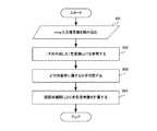
図8は、本発明の色変換LUTを用いた色変換処理方法の処理フローチャートを示す。図8を参照して、色変換LUTを用いた色変換処理を説明する。図8において、図1のcmyk色変換処理部101より出力されたCMYK画像データのcmy成分は、CMYKOG色変換処理部102に入力される。 FIG. 8 is a process flowchart of a color conversion processing method using the color conversion LUT of the present invention. A color conversion process using the color conversion LUT will be described with reference to FIG. In FIG. 8, the CMY component of the CMYK image data output from the cmyk color
ステップ801において、cmy入力信号値を読み込む。ここでの信号値とは、プリンタで紙に印字する際の各色色材量を決定するための色材信号値であり、0〜255までの256階調のデータで構成されているものとする。 In
ステップ802では、予め作成しておいた色変換LUTを読み込む。このとき、色変換LUTは、プリンタ内部に設けたハードディスクあるいは、プリンタ外部に設けた外部記憶装置等に予め記録しておき、色変換処理を施す際に、前記記憶装置から呼び出すようにすれば良い。なお、色変換LUTの詳細は、図7で既に説明した通りである。 In
ステップ803では、ステップ801で読み込まれた入力信号(c,m,y)から、予めcmy入力色空間で分割された四面体のどれに属するかを判定する。判定の際には、ステップ802で参照される色変換LUTから、cmy入力色空間で分割された各四面体の入力cmy頂点座標を参照し、四面体を構成する4つの面の平面方程式より内外判定を行えば、どの四面体に属するかを判定することができる。 In
ステップ804では、ステップ803でどの四面体に属するかが判定されるので、その四面体に対応する色変換行列を読み込み、四面体を構成する4頂点のcmy入力信号ならびに、色変換行列を用いて行列演算することで、多色信号値(C,M,Y,O,G)に変換する。色変換行列は図7で説明したように、色分解LUTの一部に含まれるので、ステップ702で参照する色変換LUTから読み込むようにすれば良い。 In
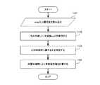
図9は、墨量に応じた色変換LUT作成方法の処理フローチャートを示す。以上では、cmyk入力色信号のうち、k信号は考慮せずに、cmy信号からCMYOG信号への変換方法に関して説明した。図9を参照して、cmyk入力信号のうち、墨量kを考慮した色変換LUT作成方法について説明する。 FIG. 9 is a process flowchart of a color conversion LUT creation method corresponding to the black amount. In the above, the conversion method from the cmy signal to the CMYOG signal has been described without considering the k signal among the cmyk input color signals. With reference to FIG. 9, a color conversion LUT creation method in consideration of the black amount k among the cmyk input signals will be described.
ステップ901において、墨量Kを設定する。墨量はブラック色材信号値を指すものであり、その範囲は0〜255までの256階調とする。なお、墨量Kの設定は、予め任意の値をしておくか、あるいは、ユーザーインターフェースを設けて、ユーザーが自由に入力できるようにしてもよい。墨量Kの設定の際に、K=0とした場合は、図2で説明した色変換LUT作成方法と同じとなる。 In
次に、ステップ902では、ステップ901で設定したK色材と、K色材以外のうちの1色、の混色での最高彩度となる色の情報、ならびに、ステップ901で設定したK色材と、特色色材と、隣接プロセス色材のうちの1色、の3次色での最高彩度となる色の情報、ならびに、ステップ901で設定したK色材を考慮したプロセス色材2次色ベタ対応色となる色の情報と、を取得する。 Next, in
まず、ステップ901で設定したK色材信号値を固定して、K以外の各色材1色でその色材信号値を0〜255まで滑らかに変化させた時の、最高彩度点となる色の情報を取得する。 First, the K color material signal value set in
次に、ステップ901で設定したK色材信号値を固定して、特色色材と隣接プロセス色材のうちの1色との混色で、各色材信号値0〜255まで等量で滑らかに変化させた時の、最高彩度点となる色の情報を取得する。 Next, the K color material signal value set in
次に、ステップ901で設定したK色材信号値を固定して、隣接プロセス色材2色の混色で、各色材信号値を0〜255まで等量で滑らかに変化させた時の最高彩度点となる色の情報を取得する。そして、K色材信号値を固定して、特色色材と隣接プロセス色材のうちの2色の混色の組み合わせの中から、前記隣接プロセス色材2色の混色の最高彩度点の色の同色相である色の情報を取得する。以下では、この色をプロセス色材2次色ベタ対応色と呼ぶことにする。例えば、特色色材をグリーンとする場合には、まず、予め設定しておいたK色材と隣接プロセス色材であるシアンとイエローの混色で最高彩度となる色の情報を取得しておき、次に、グリーン、シアン、イエローのうちのどれか2色とK色材の混色で、K色材とシアンとイエローの混色の最高彩度の色の色相と同等となる色の情報を取得することになる。 Next, the maximum color saturation when the K color material signal value set in
次に、ステップ903では、cmy入力色空間の最高彩度の辺上に上記ステップ902で取得した各色最高彩度の色を色情報に基づいて色相順に配置する。さらに、最高彩度の辺上に配置された各色最高彩度の色の点の隣接点間の色情報に基づいて、割り付けを行う。cmy入力色空間上への色材信号値の割り付け方法については、図3で詳細に説明している。 Next, in
次に、ステップ904では、ステップ903でcmy入力色空間に割り付けられた各色材最高彩度の色の点を基に複数の四面体に分割する。cmy入力色空間の四面体分割方法については、図4、図5で詳細に説明している。 Next, in
次に、ステップ905では、ステップ904で分割された各四面体頂点データを基に色変換LUTを作成する。色変換LUTの詳細については、図6で詳細に説明している。 Next, in
図10は、墨量に応じて作成された色変換LUTを用いた色変換処理のフローチャートを示す。図2〜図8では、k=0として、cmy入力色空間への出力色材信号値の割り付けと四面体分割方法について示し、cmy入力3次元データからCMYOG出力5次元データへの変換方法を説明した。 FIG. 10 is a flowchart of color conversion processing using the color conversion LUT created according to the black amount. 2 to 8, the assignment of output color material signal values to the cmy input color space and the tetrahedral division method are shown with k = 0, and the conversion method from the cmy input 3D data to the CMYOG output 5D data is described. did.
図10では、cmyk入力4次元データからCMYKOG出力6次元への変換方法に関して説明する。まず、図3、図4では、k=0としてcmy入力色空間への出力信号値の割り付けを行ったが、任意の入力kに対しても同様の処理を行うことで、色変換LUTを作成しておく。例えば、k=k1、k2、k3、・・・、kn(k1≠k2≠k3≠・・・≠kn)としてk値に応じて複数個の色変換LUTを作成しておく。なお、墨量kに応じた色変換LUT作成方法は図9で説明した。 In FIG. 10, a method for converting the CMYK input 4D data to the CMYKOG output 6D will be described. First, in FIG. 3 and FIG. 4, output signal values are assigned to the cmy input color space with k = 0, but a color conversion LUT is created by performing the same processing for any input k. Keep it. For example, k = k1, k2, k3,..., Kn (k1 ≠ k2 ≠ k3 ≠ ... ≠ kn), and a plurality of color conversion LUTs are created according to k values. The color conversion LUT creation method corresponding to the black amount k has been described with reference to FIG.
次に、図10を参照しながら、入力信号cmykの墨量kに応じた色変換LUTを用いた色変換処理方法を説明する。図10において、図1のcmyk色変換処理部101より出力されたCMYK画像データのcmyk成分は、CMYKOG色変換処理部102に入力される。 Next, a color conversion processing method using a color conversion LUT corresponding to the black amount k of the input signal cmyk will be described with reference to FIG. 10, the CMYK component of the CMYK image data output from the CMYK color
ステップ1001では、cmyk入力信号値を読み込む。次にステップ1002では、入力信号kが予め作成しておいた何点かのk値(k1、k2、k3、・・・)のどの区間に位置するかを判定する。例えば、k=0,128,255に応じた色変換LUTを予め作成していて、入力k=100の場合、入力kは区間0〜128に位置していると判定することができる。このとき、選択された区間の両端のうちk値が小さい方をkmin、大きい方をkmaxとする。 In
ステップ1003では、ステップ1002で判定された区間の両端の色変換LUTを用いて、各々で多色信号値を計算する。k=kminで作成した色変換LUTを用いて変換した多色信号値(CMYOG)k=kminと、k=kmaxで作成した色変換LUTを用いて変換した多色信号値(CMYOG)k=kmaxを計算することになる。 In
ステップ1004では、ステップ1003で計算したk値に応じた2つの多色信号値(CMYOG)k=kmin、(CMYOG)k=kmax、ならびに入力kとを用いて補間計算を行い、入力kに対応する多色信号値を計算する。なお、上記のパラメータを用いて、任意の入力信号kに対する多色信号値(CMYOG)kは次式で求めることができる。 In
ステップ1005では、入力信号kを出力信号Kとして、ステップ1004で計算したKを除いた多色信号値(CMYOG)とを結合して、6色で構成されるCMYKOG多色出力信号値を形成する。 In
以上説明したように、実施例1では、特色色相において、プロセス色材と特色色材の混色で最高彩度となる色を、入力cmyk空間の最高彩度に相当する辺上に色相順に配置して、隣接する点(色)間の色差に応じて割り付け、その割り付けに応じた色変換LUTを作成するので、隣接色相間での階調性の低下を抑制することができる。また、特色色相において、最高彩度点よりも低明度側で特色色材とその特色と色相的に隣接するプロセス色材を混色するような組み合わせとなるように割り付けているので、低明度色域でも色再現範囲を十分に活用することができる。 As described above, in the first embodiment, in the special color hue, the color having the highest saturation in the mixed color of the process color material and the special color material is arranged in the order of the hue on the side corresponding to the highest saturation of the input cmyk space. Thus, assignment is performed according to the color difference between adjacent points (colors), and a color conversion LUT corresponding to the assignment is created, so that it is possible to suppress a reduction in gradation between adjacent hues. Also, in the special color hue, the color is assigned so that the special color material and the process color material adjacent to the special color are mixed on the low lightness side of the maximum saturation point. However, the color reproduction range can be fully utilized.
従来、特色色相で最高彩度点からブラックポイントまで特色と基本色を混色することで、広色域化を図ろうとしている。しかし、最高彩度点からブラックポイントまでの色域に対しては、特色と基本色を必ず混色しているので、基本色のみの組み合わせの方が広色域の場合には、再現可能な色域を十分に活用できていない。 Conventionally, a special color hue and a basic color are mixed from the maximum saturation point to the black point to increase the color gamut. However, for the color gamut from the highest saturation point to the black point, the special color and the basic color are always mixed, so if the combination of only the basic colors has a wider color gamut, it is a reproducible color. The area is not fully utilized.
そこで、実施例2では、CMYKデバイス信号を、特色を含むN色デバイス信号へ色変換する際に、N色で再現可能な色域を十分に活用するような色変換を実現する。すなわち、実施例2は、特色色材を含むN色信号への色変換処理を行う際に、最高彩度点からブラックポイントまでの低明度色域において、特色を主とした混色と、基本色のみの混色と、特色と基本色の混色で、それぞれ再現可能な色域を比較して、その比較結果をもとに、入力cmy色空間の最高彩度点からブラックポイントに相当する辺上に割り付けている。 Therefore, in the second embodiment, when color conversion is performed from a CMYK device signal to an N-color device signal including a spot color, color conversion that fully utilizes a color gamut reproducible with N colors is realized. That is, in the second embodiment, when color conversion processing to an N color signal including a special color material is performed, in the low brightness color gamut from the highest saturation point to the black point, the mixed color mainly including the special color and the basic color Compare the reproducible color gamuts with only the mixed color and the mixed color of the special color and the basic color, and based on the comparison result, on the side corresponding to the black point from the highest saturation point of the input cmy color space Allocated.
図1は、本発明の実施例2の色変換LUT作成方法で作成した色変換LUTを用いた色変換処理装置の構成を示す。画像処理部100に入力画像として、RGBや独立色空間CIE L*a*b*などで構成されるデータが入力されると、cmyk色変換処理部101は、入力画像データをcmyk画像データに変換し、CMYKOG色変換処理部102へ渡す。ここで、cmyk画像データとは、出力するプリンタをCMYKプリンタとみなし生成された画像データのことで、すなわち、cmyk色変換処理部101には、CMYK変換に対応した一般的な色変換方法を利用できる構成が採用される。また、CMYKOGはそれぞれ、シアン(C)、マゼンタ(M)、イエロー(Y)、ブラック(K)、およびオレンジ(O)、グリーン(G)の紙に印字する際に使用する色材量を決定するための色材信号であり、各色256階調で、各色材信号は0〜255の範囲とする。以下ではCMYKを基本色色材、CMYの中間色相の色を有するO、Gなどの色材を特色色材と呼ぶこととする。 FIG. 1 shows the configuration of a color conversion processing apparatus using a color conversion LUT created by the color conversion LUT creation method of
CMYKOG色変換処理部102は、cmyk色変換処理部101によって変換されたcmyk画像データを受け取り、色変換LUT104を参照して、CMYKOGの画像信号へと変換する。なお、色変換LUT104は予め作成しておき、プリンタ内部のハードディスクあるいは、プリンタ外部の記憶装置等に保存しておき、変換処理をする際に参照できるようにしておくとよい。そして、CMYKOGの画像信号が出力画像データとして生成され、その画像データをもとに、画像形成装置で画像が印刷される。CMYKOG色変換処理部102で行われる一連の処理の詳細は、図21で説明する。 The CMYKOG color
ただし、実際に印刷する際には、CMYKOGの画像データに変換した後に、色材信号総量が予め設定された制限値を超えていないかどうかを判定し、超えているようであれば、総量規制値を超えないように各色材信号を修正する。また、修正された色材信号に対して、階調処理が施される。これは、画像データは256階調数を有するのに対して、画像形成装置では、各画素に対してドットを形成するか否か、あるいは数種のドットサイズを制御することでしか階調性を表現できない。そのため、CMYKOGの画像データを誤差拡散やディザ等の方法により、画素毎のドット形成を表す記録データにする。 However, when actually printing, after converting to CMYKOG image data, it is determined whether the total amount of color material signals does not exceed a preset limit value. Each color material signal is corrected so as not to exceed the value. Further, gradation processing is performed on the corrected color material signal. This is because the image data has 256 gradations, but the image forming apparatus can only perform gradation by controlling whether or not to form dots for each pixel, or by controlling several dot sizes. Cannot be expressed. Therefore, the CMYKOG image data is converted into recording data representing dot formation for each pixel by a method such as error diffusion or dithering.
色変換LUT作成部103は、基本色色材単色、ならびに、特色色材とその特色と色相的に隣接する基本色色材とを混色した色の情報をもとに、cmy入力色空間上にCMYOGの色材信号を割り付ける。そして、割り付けた点から複数の四面体に分割し、各四面体の頂点データ群と、割り付けた入力cmyと出力CMYOGの色材信号の対応関係から算出する色変換行列のデータ群とを、結合してそれを色変換LUT104として作成する。色変換LUT作成部103で行われる一連の処理の詳細は、図11で説明する。 The color conversion
図11は、実施例2の色変換LUTを用いた色変換処理方法のフローチャートを示す。以下、図11を参照して、色変換LUTを用いた色変換処理を説明する。図11において、図1のcmyk色変換処理部101より出力されたCMYK画像データのcmy成分がCMYKOG色変換処理部102に入力される。 FIG. 11 is a flowchart of a color conversion processing method using the color conversion LUT according to the second embodiment. Hereinafter, the color conversion process using the color conversion LUT will be described with reference to FIG. In FIG. 11, the CMYK image data output from the CMYK color
ステップ1101では、cmy入力信号値を読み込む。信号値とは、プリンタで紙に印字する際の各色色材量を決定するための色材信号値であり、各色0〜255までの256階調のデータで構成されているものとする。 In
ステップ1102では、予め作成しておいた色変換LUT104を読み込む。このとき、色変換LUT104は、プリンタ内部に設けたハードディスク、あるいはプリンタ外部に設けた外部記憶装置等に予め記録しておき、色変換処理を行う際に、記憶装置から参照するようにすればよい。色変換LUT104の作成方法に関しては、図12で詳細に説明する。 In
ステップ1103では、ステップ1102で読み込まれた入力信号(c,m,y)から、予めcmy入力色空間で分割された四面体のどれに属するかを判定する。判定の際には、ステップ1102で参照される色変換LUT104から、cmy入力色空間で分割された各四面体の入力cmy頂点座標を参照し、四面体を構成する4つの面の平面方程式より内外判定を行えば、どの四面体に属するかを判定することができる。 In
ステップ1104では、ステップ1103でどの四面体に属するかが判定されるので、その四面体に対応する色変換行列を読み込み、四面体を構成する4頂点のcmy入力信号ならびに、色変換行列を用いて行列演算することで、多色信号値(C,M,Y,O,G)に変換する。 In
図12は、実施例2の色変換処理で用いられる色変換LUT作成方法のフローチャートを示す。以下、図12を参照して、色変換LUT作成方法を説明する。 FIG. 12 is a flowchart of a color conversion LUT creation method used in the color conversion processing according to the second embodiment. Hereinafter, the color conversion LUT creation method will be described with reference to FIG.
ステップ1201において、単色ベタ、特色とその特色と色相的に隣接する基本色1色の混色ベタ、の色情報を色材切換え点1に設定し、基本色2色の混色ベタ、特色とその特色と色相的に隣接する基本色1色の混色で、前記基本色2色の混色ベタと等色相で且つ最高彩度となるような混色の色情報を色材切換え点群2に設定する。なお、色材切換え点とは、後述するcmy入力色立方体空間を四面体で分割する際の頂点となるデータである。また、色情報とは色材信号値ならびにデバイス独立信号値(L*a*b*)を指すものとする。以下に、色材切換え点群1、2の設定方法について説明する。 In
まず、色材切換え点群1の設定方法について説明する。単色ベタの色情報は、各色材信号を0〜255まで変化させた時に最高彩度点となる色が設定される。それに続けて、特色と基本色1色の混色ベタの色情報は、各色材信号値を0〜255まで等量で変化させた時に最高彩度点となる色が設定される。そして、これら全ての単色、ならびに特色と基本色1色の混色のベタとなる色の情報が色材切換え点群1として設定される。 First, a method for setting the color material
次に、色材切換え点群2の設定方法について説明する。基本色2色の混色ベタの色情報は、前述したのと同様に、各色材信号値を0〜255まで等量で変化させた時に最高彩度点となる色が設定される。続いて、特色と基本色1色の混色で、前記基本色2色の混色ベタと等色相で且つ最高彩度点となるような混色の色情報を設定する。 Next, a method for setting the color material
なお、以下の説明ではこの混色を「基本色2次色ベタ対応色」と呼ぶこととする。基本色2次色ベタ対応色の色情報は、特色色材信号を特色単色でベタとなる時の色材信号値で固定し、基本色1色の色材信号値を0〜255まで変化させて、基本色2色の混色ベタと等色相で、且つ最高彩度となる色が選択される。そして、これらの基本色2色の混色ベタ、ならびに基本色2次色ベタ対応色の色情報が色材切換え点群2として設定される。色材切換え点群1、2の設定方法については、図13でさらに補足説明する。 In the following description, this mixed color is referred to as “basic color corresponding to secondary color”. For the color information of the basic color corresponding to the secondary color, the special color material signal is fixed at the color material signal value when the special color is solid and solid, and the color material signal value of one basic color is changed from 0 to 255. Thus, a color having the same hue as the solid mixed color of the two basic colors and the highest saturation is selected. Then, the mixed color of these two basic colors and the color information of the color corresponding to the basic secondary color are set as the color material
次に、ステップ1202では、特色とその特色と色相的に隣接する基本色2色の混色で、色材切換え点群2で設定した2点と等色相で、且つ最高彩度となるような対象色を、色材切換え点3として新たに設定するか否かの判定を行う。色材切換え点3を設定するか否かの判定方法に関しては、図14、図15で詳細に説明する。 Next, in
次に、ステップ1203では、ステップ1202で判定した結果を基に、色材切換え点3を新たに設定する。なお、ステップ1202の判定において、色材切換え点3の設定の条件を満たさない場合には、色材切換え点3は設定せずに、次ステップ1204へ処理を移すことになる。色材切換え点3の設定方法については、図14、図15で詳細に説明する。 Next, in
次に、ステップ1204では、ステップ1201、ステップ1203で設定した色材切換え点群1、2、および色材切換え点3を基に色変換LUT作成を作成する。色変換LUT作成方法については、図16で詳細に説明する。 In
図13は、実施例2の色材切換え点群1、2の設定方法を説明する図である。図13は、デバイス独立色空間におけるL*C平面を示し、この図を参照して、色材切換え点群1、2の設定方法を説明する。 FIG. 13 is a diagram illustrating a method for setting the color material
まず、色材切換え点群1には、単色ベタ、および特色とその特色と色相的に隣接する基本色1色の混色ベタの色情報を設定する。図13(A)では、CMYOGの色材を用いる場合の色材切換え点群1の設定を示したものである。まず、C、M、Y、O、Gの各色材単色で最高彩度点となる色(単色ベタ)の情報が設定される。続いて、特色色材とその特色と色相的に隣接する基本色色材1色の二次混色であるYG、CG、YO、MOの各色で最高彩度となる色(特色+基本色1色の混色ベタ)の色情報が設定される。例えば、YGの場合には、YとGの色材信号値を0〜255まで等量ずつ変化させていき、最高彩度点となる時の色が設定されることになる。このようにして、色材切換え点群1に各色情報が設定される。 First, in the color material
次に、色材切換え点群2には、基本色2色の混色ベタ、および特色とその特色と色相的に隣接する基本色1色で、前記基本色2色の混色ベタと等色相で、且つ最高彩度となるような混色(基本色2次色ベタ対応色)の色情報を設定する。図13(B)では、CMYOGの色材を用いる場合の色材切換え点群2の設定を示したものである。まず、基本色2色の二次混色である、MY、CYの各色で最高彩度となる色(基本色2色の混色ベタ)の色情報が設定される。例えば、MYの場合には、MとYの色材信号値を0〜255まで等量ずつ変化させていき、最高彩度点となる時の色が設定される。続いて、基本色2次色ベタ対応色である色情報が設定される。例えば、O色材を有する色相の場合には、まずO単色ベタとなる時の色材信号値を参照する。そして、この時の信号値が245ならば、O色材信号値を245で固定して、MもしくはYのどちらか一方の色材信号値を0〜255まで変化させた時に、MYの2色の混色ベタと等色相で、且つ最高彩度点となる色が設定されることになる。つまり、O色相(MY色相)では、O、OM、OYのうちどれかの色情報が基本色2次色ベタ対応色として設定される。このようにして、色材切換え点群2に各色情報が設定される。 Next, the color material
図14は、実施例2の色材切換え点3の追加判定の処理フローチャートを示す。図15は、実施例2の色材切換え点3の追加判定条件を説明する図である。以下、図14、15を参照して、色材切換え点3を追加するか否かを判定する方法を説明する。 FIG. 14 is a flowchart illustrating a process for adding the color
ステップ1301では、色材切換え点群2に設定した、基本色色材2色の混色ベタ、ならびに基本色2次色ベタ対応色の色情報を参照する。なお、これらの色情報については、図13で説明した。 In
次に、ステップ1302では、特色とその特色と色相的に隣接する基本色2色の三次混色で、ステップ1301で参照した2点と等色相で、且つ最高彩度となるような対象色の色情報を参照する。例えば、CMYOGの色材が使用される場合のO色相では、MYOの3色の混色で、MY2色の混色ベタ、ならびにMY2次色ベタ対応色と等色相で、且つ最高彩度となる色が参照される。なお、ここで参照される特色と基本色色材2色の混色を以下では「対象色」と呼ぶこととする。 Next, in
次に、ステップ1303では、ステップ1301で参照された色材切換え点群2の2点を結ぶ線分に対し(2点の混色ベタとの色空間座標での位置関係に基づいて)、ステップ1302で参照した対象色が、色差一定以上の外側の位置にあるかを判定する。図15(A)で示すように、ステップ1301で参照した基本色2色の混色ベタと基本色2次色ベタ対応色をL*a*b*色座標空間上で結んだ線分に対して、ステップ1302で参照した対象色が色差α(所定の閾値)以上外側にあるか否かを判定し、α以上であればステップ1304の処理へ移行し、α未満であればステップ1306へ移行し、色材切換え点3を新たに設定するのは適切ではないと判定し、全ての処理を終了する。なお、色差α以上としているのは、突出量が小さい場合、ステップ1302で参照した対象色を新たに色材切換え点3として設定しても、処理の煩雑さが増すだけで、色域拡大の効果が極めて低いためである。 Next, in
次に、ステップ1304では、ステップ1301で参照された色材切換え点群2の2点と、ステップ1302で参照した対象色との各色差が一定以上であるか否かを判定する。図15(B)で示すように、ステップ1301で参照した基本色2色の混色ベタと基本色2次色ベタ対応色と、ステップ1302で参照した対象色との各色差がβ(所定の閾値)以上であるか否かを判定し、β以上であればステップ1305の処理へ移行し、β未満であればステップ1306へ移行し、色材切換え点3を新たに設定するのは適切ではないと判定し、全ての処理を終了する。なお、色差β以上としているのは、各色材切換え点間の色差が小さい場合、急激な色材構成の変化によって生じる質感変化を防ぐためである。 Next, in
次に、ステップ1305では、色材切換え点3を設定可能と判定する。前記ステップ1303、1304の各条件を満たした場合、ステップ1302で参照した対象色、具体的には、特色色材とその特色と色相的に隣接する基本色2色で構成される色、を色材切換え点3として設定することは適切であると判定する。そして、ステップ1305の処理を終えた時点で、色材切換え点3の設定が完了する。 Next, in
このように、各色材構成で再現可能な色域を比較し、その結果を基に新たな色材切換え点を設定するかどうかを判定し、色材切換え点を設定するので、プリンタで再現可能な色域に対して損失の少ない色変換を達成することが可能となる。また、色材切換え点間の色差が一定以上あるかどうかを判定し、その結果を基にガマット最外郭を構成する色材切換え点を設定するので、色材構成が切換わる色域でも印刷物の質感(見た目)の不連続性がない色変換を達成することが可能となる。また、基本色2色の混色ベタの点と、特色とその特色と色相的に隣接する基本色2色の混色の点とを、cmy色立方体空間の等色相面に割り付けているので、色材構成が切換わる部分でも色相変化が少ない滑らかな色変換を達成することが可能となる。 In this way, the color gamut that can be reproduced with each color material configuration is compared, and based on the result, it is determined whether a new color material switching point is set, and the color material switching point is set. Therefore, it is possible to achieve color conversion with little loss for a wide color gamut. In addition, it is determined whether the color difference between the color material switching points is a certain level or more, and based on the result, the color material switching points that constitute the outermost outline of the gamut are set, so even in the color gamut where the color material configuration is switched, It becomes possible to achieve color conversion without discontinuity in texture (appearance). Also, since the solid color point of the two basic colors and the special color and the mixed color point of the two basic colors that are adjacent to the special color are assigned to the uniform hue plane of the cmy color cubic space, It is possible to achieve smooth color conversion with little change in hue even at the portion where the configuration is switched.
図16は、実施例2の色変換LUT作成方法の詳細なフローチャートを示す。以下、図16を参照して、図12の色変換LUT作成方法のフローチャートにおける、ステップ1204で行われる色材切換え点を基に色変換LUTの作成方法を説明する。 FIG. 16 is a detailed flowchart of the color conversion LUT creation method according to the second embodiment. Hereinafter, a method for creating a color conversion LUT will be described based on the color material switching point performed in
ステップ1401では、色材切換え点を参照する。図12のフローチャートのステップ1201〜1203の処理において、色材切換え点群1、2、および、色材切換え点3をそれぞれ設定したので、これら各点の色情報(色材信号値、L*a*b*)を参照する。なお、色材切換え点3については、一定の条件を満たしていない場合には設定されずに色材切換え点1、2のみが参照されることになるが、以下の説明では色材切換え点3が設定されている場合について説明する。また、各色材切換え点の設定方法については前述しているため、ここでは説明は省略する。 In
次に、ステップ1402では、cmy入力色空間の色立方体辺上に、ステップ1401で設定した各色材切換え点をL*a*b*値に基づいて配置する。さらに各辺上に配置された各色材切換え点の隣接点間の色情報に基づいて、割り付けを行う。cmy入力色空間上への色材切換え点の割り付け方法については、図17、図18で詳細に説明する。 Next, in
次に、ステップ1403では、ステップ1402でcmy入力色空間に割り付けられた各色材切換え点を基に複数の四面体に分割する。cmy入力色空間の四面体分割方法については、図19、図20で詳細に説明する。 Next, in
次に、ステップ1403では、ステップ1403で分割された各四面体頂点データを基に色変換LUTを作成する。色変換LUTの詳細については、図21で詳細に説明する。 Next, in
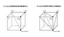
図17は、cmy入力色空間上への色材切換え点の割り付け方法の処理フローを示す。図18は、cmy入力色空間上への色材切切換え点の割り付けの具体例を説明する図である。以下、図17、18を参照して、cmy入力色空間上への色材切換え点の割り付け方法を説明する。 FIG. 17 shows a processing flow of the method for assigning color material switching points on the cmy input color space. FIG. 18 is a diagram for explaining a specific example of the allocation of the color material cutting switching points on the cmy input color space. Hereinafter, with reference to FIGS. 17 and 18, a method for assigning the color material switching points on the cmy input color space will be described.
ステップ1501では、cmy入力色空間上に白、および黒に対応する点を割り付ける。図18(A)は、k=0として、入力色空間をcmyの3次元色空間に簡略した図である。そのため、図示した立方体の表面は入力色空間最外郭の一部のみを示しており、以下では、C−Y色相の割り付け方法について説明する。なお、入力信号CMYKと出力信号CMYKOGとを区別するために、入力信号CMYKを小文字のcmyk信号と表記する。cmy入力色空間において、(c,m,y)=(0,0,0)の点は白、(c,m,y)=(255,255,255)の点は黒である。よって、cmy入力色空間の白に相当する点が、出力信号値でも白となるように、(C,M,Y,K,O,G)=(0,0,0,0,0,0)を割り付ける。また、cmy入力色空間の黒に相当する点には、入力信号値をそのまま出力するように、(C,M,Y,K,O,G)=(255,255,255,0,0,0)を割り付ける。ここで、白と黒に対応する点を結ぶ直線は、無彩色の集まりであるので、以下では、この直線を無彩色軸と呼ぶ。また、cmy入力色空間において、白および黒に相当する点を通らない立方体の各辺は、各色相の最高彩度点に対応する。以下ではこれらの辺を最高彩度の辺と呼ぶ。 In
次に、ステップ1502では、cmy入力色空間上に基本色単色ベタを割り付ける。なお、基本色単色ベタは色材切換え点群1の一部として設定している。図18(B)は、cmy入力色空間の最高彩度の辺上に基本色単色ベタの色材切換え点を割り付けた図である。cmy入力色空間のc、m、y各軸ではcmy入力信号と出力信号のCMYが同じになるようにするため、入力色空間のc、m、y各軸255の点に基本色単色ベタの色材切換え点を割り付ける。こうすることで、単色色信号が入力された場合には、出力色信号でも単色となることが保証される。 Next, in
次に、ステップ1503では、cmy入力色空間上に基本色2次色ベタ対応色の点を割り付ける。なお、基本色2次色ベタ対応色は色材切換え点群2の一部として設定している。図18(C)は、cmy入力色空間の最高彩度の辺上に基本色2次色ベタ対応色に相当する色材切換え点を割り付けた図である。cmy入力色空間の(c,m,y)=(255,0,255)の点に、基本色2次色ベタ対応色の色材切換え点を割り付ける。 Next, in
次に、ステップ1504では、特色単色ベタ、ならびに特色と基本色1色の混色ベタに相当する色材切換え点を、cmy入力色空間の最高彩度の辺上に色相順に配置する。なお、特色単色ベタ、ならびに特色と基本色1色の混色ベタは色材切換え点群1の一部として設定している。図18(D)は、cmy入力色空間の最高彩度の辺上に特色単色ベタ(G)、特色と基本色1色による混色ベタの色(Y+G、C+G)に相当する色材切換え点を色相順に配置した図である。各色材切換え点の色情報は既知であるので、各点の色相角を参照して、特色単色ベタ、ならびに、特色と基本色1色による混色ベタの色を色相順に配置する。 Next, in
次に、ステップ1505では、cmy入力色空間上に基本色2色の混色ベタ、ならびに、特色と基本色2色の三次混色で、色材切換え点群2に設定した2点と等色相で、且つ最高彩度となる色に相当する色材切換え点(対象色)を配置する。なお、基本色2色の混色ベタは色材切換え点群2の一部として、特色と基本色2色の混色(対象色)は色材切換え点3として、それぞれ設定されている。図18(E)は、cmy入力色空間の基本色2次色ベタ対応色と黒を結んだ線上に、基本色2色の混色ベタの色(C+Y)、特色と基本色2色の混色で、基本色2色の混色ベタと等色相で最高彩度となる色(C+Y+G)に相当する色材切換え点を配置した図である。これらの色は、各色相面において最高彩度点ではないので、最高彩度の辺上には割り付けず、立方体表面の黒寄りの位置に配置する。また、黒に近いほど明度が低くなるので、C+Yの点を黒寄りの位置に配置する。 Next, in
次に、ステップ1506では、ステップ1504、1505で配置した各点を隣接間色差に応じて割り付ける。図18(F)は、各色材切換え点を隣接間色差に基づいて、割り付け位置を決定した図である。 Next, in
まず、cmy入力色空間の最高彩度に配置した色材切換え点の割り付け方法を説明する。ステップ1504の処理を終えて、基本色単色ベタ、特色単色ベタ、特色と基本色1色の混色ベタ、基本色2次色ベタ対応色が、cmy入力色空間の最高彩度の辺上に色相順に配置された。次にこれらの点を色相順に並べた時の隣接間色差に応じて、割り付け位置を決定していく。図18(E)のY単色から基本色2次色ベタ対応色までの割り付け方法を例に説明する。まず、色相順に並べられたY単色ベタ(Y)、YG2次色ベタ(Y+G)、G単色ベタ(G)、プロセス色材2次色ベタ対応色の各隣接間(Y〜YG、YG〜G、G〜基本色2次色ベタ対応色)色差をΔE1、ΔE2、ΔE3とする。この場合、Y〜基本色2次色ベタ対応色間の累積色差ΔE_totalとすると、ΔE_total=ΔE1+ΔE2+ΔE3となる。よって、YGの位置はYから、(ΔE1)/(ΔE_total)の位置に割り付ける。Gの位置はYから、(ΔE1+ΔE2)/(ΔE_total)の位置に割り付ける。 First, a method for assigning the color material switching points arranged at the maximum saturation of the cmy input color space will be described. After the processing of
こうすることで、入力cmykに対して、色差ひずみの少ない変換を容易に実現することができる。これと同様にして、C単色から基本色2次色ベタ対応色までの割り付けを行うことで、YC色相におけるcmy入力色空間の最高彩度の辺上への割り付けが完了する。また、基本色2次色ベタ対応色〜黒を結ぶ線上に配置した基本色2色の混色ベタ(C+Y)、特色と基本色2色の混色(C+Y+G)も上記と同様にして、隣接点間色差に応じて割り付ける。 By doing so, conversion with little color difference distortion can be easily realized for the input cmyk. In the same manner, by performing the allocation from the C single color to the basic color corresponding to the secondary secondary color, the allocation to the highest chroma side of the Cmy input color space in the YC hue is completed. Similarly, the solid color (C + Y) of the two basic colors arranged on the line connecting the color corresponding to the secondary color of the secondary color to black, and the mixed color of the special color and the basic color (C + Y + G) are also between adjacent points. Assign according to the color difference.
なお、図18では、グリーン(G)色相を例に説明したが、オレンジ(O)やその他の中間色相の色材を使用する場合も同様にして、cmy入力色空間へ色材切換え点の割り付けを行う。 In FIG. 18, the green (G) hue has been described as an example. However, in the case where orange (O) or other intermediate hue is used, the color material switching points are assigned to the cmy input color space in the same manner. I do.
図19は、実施例2のcmy入力色空間上での四面体分割方法の具体例を説明する図である。図17、図18で説明したように、cmy入力色空間に各色材切換え点の割り付けを完了したら、次に割り付けた各色材切換え点ならびに、白、黒に対応する点を頂点とする四面体で分割していく。 FIG. 19 is a diagram illustrating a specific example of a tetrahedron dividing method on the cmy input color space according to the second embodiment. As described with reference to FIGS. 17 and 18, when the assignment of each color material switching point to the cmy input color space is completed, each color material switching point and a tetrahedron having points corresponding to white and black as apexes are assigned. Divide.
図19(A)は、cmy入力色空間に割り付けられた各色材切換え点と、白ならびに黒に対応する点を結んで、四面体に分割した例を示している。分割する際には、四面体を構成する4頂点のうちに必ず、白に対応する点を含むようにして、その他の3点は四面体分割の時に重複部分がないように選択する。図19(B)は、図19(A)の各頂点を結んで分割された四面体をそれぞれ分解して示したものである。なお、図19(A)の色材切換え点に対して、図19(B)以外の四面体分割も可能であるが、ここでは説明の簡略のため、これらを図示することは省略する。 FIG. 19A shows an example in which each color material switching point assigned to the cmy input color space is connected to points corresponding to white and black and divided into tetrahedrons. When dividing, make sure that the four vertices constituting the tetrahedron include a point corresponding to white, and select the other three points so that there is no overlap when dividing the tetrahedron. FIG. 19B is an exploded view of the tetrahedron divided by connecting the vertices of FIG. 19A. In addition, although the tetrahedron division other than FIG. 19B is also possible with respect to the color material switching point in FIG. 19A, the illustration thereof is omitted here for the sake of simplicity.
図19では、グリーン色相(Y−C色相間)を例に説明したが、オレンジ(O)やその他の中間色相の色材を使用する場合も同様にして、cmy入力色空間を複数の四面体に分割する。 In FIG. 19, the green hue (between Y and C hues) has been described as an example. However, in the case where orange (O) or other intermediate hue color materials are used, the cmy input color space is similarly divided into a plurality of tetrahedrons. Divide into
図20は、実施例2の特色色材を有さない色相間でのcmy入力色空間の色材切換え点の割り付けと、四面体分割方法を説明する図である。図17〜図19では、グリーン色相(Y−C色相間)を例に特色色材を有する色相間でのcmy入力空間への色材切換え点の割り付け、ならびに四面体分割方法について示した。ここでは、特色色材を有さない色相間での場合について説明する。例えば、CMYKOG色材を用いる場合には、ブルー色相(C−M色相間)がこの場合に該当する。よって、以下ではブルー色相を例に割り付け方法、ならびに四面体分割方法を説明する。 FIG. 20 is a diagram for explaining the assignment of the color material switching points in the cmy input color space between hues that do not have the special color material of Example 2 and the tetrahedron division method. In FIGS. 17 to 19, the assignment of the color material switching points to the cmy input space between the hues having the special color material and the tetrahedron division method are shown by taking the green hue (between Y-C hues) as an example. Here, a case between hues that do not have a special color material will be described. For example, when a CMYKOG color material is used, a blue hue (between CM hues) corresponds to this case. Therefore, the assignment method and the tetrahedron division method will be described below by taking blue hue as an example.
特色色材を有さない色相間では、cmy入力色空間の最高彩度の辺上、ならびに基本色2次色ベタ対応色〜黒を結ぶ辺上に割り付けるべき特色色材を用いた色材切換え点が存在しないので、基本色2色の混色ベタに相当する色材切換え点を、cmy入力色空間立方体の対応する頂点に割り付ける。図20(A)は、ブルー色材を有さない場合での、ブルー色相間におけるcmy入力色空間への色材切換え点の割り付けを示している。 Between hues that do not have a special color material, color material switching using a special color material that should be allocated on the side of the highest saturation of the cmy input color space and on the side connecting the basic color secondary color solid color to black Since no point exists, a color material switching point corresponding to a mixed color of two basic colors is assigned to the corresponding vertex of the cmy input color space cube. FIG. 20A shows allocation of color material switching points to the cmy input color space between blue hues when there is no blue color material.
また、四面体分割方法に関しては、特色色材を有さない色相でも図17〜図19で説明した特色色材を有する場合と同様にして、白ならびに黒に対応する点と、最高彩度の辺上に割り付けられた各色材切換え点のうち、隣接する2点が四面体頂点に選択されるようにする。図20(B)は、ブルー色相間におけるcmy入力色空間を四面体に分割した例を示している。 As for the tetrahedron division method, even in a hue that does not have a special color material, as in the case of having the special color material described with reference to FIGS. Among the color material switching points assigned on the side, two adjacent points are selected as tetrahedral vertices. FIG. 20B shows an example in which the cmy input color space between blue hues is divided into tetrahedrons.
図21は、実施例2の色変換LUTを説明する図である。図19、20では、cmy入力色空間を複数の四面体に分割する一連の処理を説明した。次に、図21を参照しながら、各四面体の頂点構成データを用いて、色変換LUT作成までの流れを示す。 FIG. 21 is a diagram illustrating the color conversion LUT according to the second embodiment. 19 and 20, the series of processes for dividing the cmy input color space into a plurality of tetrahedrons has been described. Next, referring to FIG. 21, the flow up to the creation of the color conversion LUT using the vertex configuration data of each tetrahedron is shown.
cmy入力色空間の最外郭(立方体表面)の変換は各四面体頂点データを用いた四面体補間で計算することができる。各四面体の4頂点の割り付けを
(c1,m1,y1)=>(C1,M1,Y1,O1,G1)
(c2,m2,y2)=>(C2,M2,Y2,O2,G2)
(c3,m3,y3)=>(C3,M3,Y3,O3,G3)
(c4,m4,y4)=>(C4,M4,Y4,O4,G4)
とすると、前掲した式(1)、すなわち、前掲した式(2)を解くことで、補間係数X11〜X54が得られる。従って、四面体内の任意の入力信号値(c,m,y)に対しては、前掲した式(3)により出力信号値(C,M,Y,O,G)を計算すればよい。The transformation of the outermost contour (cube surface) of the cmy input color space can be calculated by tetrahedral interpolation using each tetrahedral vertex data. Assign the four vertices of each tetrahedron to (c1, m1, y1) => (C1, M1, Y1, O1, G1)
(C2, m2, y2) => (C2, M2, Y2, O2, G2)
(C3, m3, y3) => (C3, M3, Y3, O3, G3)
(C4, m4, y4) => (C4, M4, Y4, O4, G4)
Then, interpolation coefficients X11 to X54 can be obtained by solving the above-described formula (1), that is, the above-described formula (2). Therefore, for any input signal value (c, m, y) in the tetrahedron, the output signal value (C, M, Y, O, G) may be calculated by the above-described equation (3).
なお、多色出力信号値(C,M,Y,O,G)を計算するために、入力された(c,m,y)が分割された四面体のどれに属するかを判定する必要がある。その方法としては、各四面体の3頂点を結んで構成される平面の方程式から、各平面の内外判定を行えばよい。 In order to calculate the multicolor output signal value (C, M, Y, O, G), it is necessary to determine which of the divided tetrahedrons the input (c, m, y) belongs to. is there. As the method, the inside / outside determination of each plane may be performed from the equation of the plane formed by connecting the three vertices of each tetrahedron.
つまり、図20で示すように、cmy入力信号からCMYOG多色信号へ変換するために必要な多色変換行列と、cmy入力信号に対して、分割された四面体のどれに属するかを判定するために必要な四面体頂点構成データとを予め計算して、これらをまとめて結合させたものを色変換LUTとして記録する。そして、任意のcmy入力信号からCMYOG多色出力信号へ変換する際には、この色変換LUTを参照して計算すればよい。 That is, as shown in FIG. 20, a multicolor conversion matrix necessary for converting a cmy input signal to a CMYOG multicolor signal and which of the divided tetrahedrons the cmy input signal belongs to are determined. The tetrahedral vertex configuration data necessary for this is calculated in advance, and the combined data is recorded as a color conversion LUT. Then, when converting from an arbitrary cmy input signal to a CMYOG multicolor output signal, calculation may be performed with reference to this color conversion LUT.
なお、プリンタ内部のハードディスク、あるいはプリンタ外部の記憶装置等の記憶容量に制約がなければ、上記色変換LUTを使用して、cmyk入力信号に対するCMYKOG出力信号の1対1対応関係を予め計算しておき、その対応関係を記録し、このデータを色変換LUTとすることも可能である。そうすれば、cmyk入力信号からCMYKOG出力信号への色変換時に、四面体補間に掛かる計算時間を短縮することも可能である。 If the storage capacity of the hard disk inside the printer or the storage device outside the printer is not limited, the one-to-one correspondence of the CMYKOG output signal to the cmyk input signal is calculated in advance using the color conversion LUT. It is also possible to record the correspondence relationship and use this data as a color conversion LUT. By doing so, it is also possible to shorten the calculation time required for tetrahedral interpolation at the time of color conversion from the cmyk input signal to the CMYKOG output signal.
図22は、実施例2の墨量に応じた色変換LUT作成方法のフローチャートを示す。ここまでは、cmyk入力信号のうち、k信号は考慮せずに、cmy信号からCMYOG信号への変換方法に関して説明した。以下、図22を参照して、cmyk入力信号のうち、墨量kを考慮した色変換LUT作成方法について説明する。 FIG. 22 is a flowchart of the color conversion LUT creation method according to the black amount of the second embodiment. Up to this point, the conversion method from the cmy signal to the CMYOG signal has been described without considering the k signal among the cmyk input signals. Hereinafter, with reference to FIG. 22, a method for creating a color conversion LUT in consideration of the black amount k among the cmyk input signals will be described.
ステップ1601おいて、墨量Kを設定する。墨量はブラック色材信号値を指すものであり、その範囲は0〜255までの256階調とする。なお、墨量Kは、予め任意の値を設定しておくか、あるいは、ユーザーインターフェースを設けて、ユーザーが自由に入力できるようにしてもよい。墨量Kの設定の際に、K=0とした場合は、図12で説明した色変換LUT作成方法と同じとなる。 In
次に、ステップ1602では、ステップ1601で設定したK色材に加えて、各色1色との混色ベタ、特色とその特色と色相的に隣接する基本色1色との混色ベタの色の情報を色材切換え点群1に設定し、K色材に加えて、基本色2色との混色ベタ、特色とその特色と色相的に隣接する基本色1色との混色で、前記基本色2色との混色ベタと等色相で且つ最高彩度となるような混色の色の情報を色材切換え点群2に設定する。なお、色の情報とは色材信号値ならびにデバイス独立信号値(L*a*b*)を指すものとする。 Next, in
まず、K色材に加えて、各色1色との混色ベタの色の情報は、ステップ1601で設定したK色材信号値を固定して、各色材信号値を0〜255まで変化させた時に最高彩度点となる色が設定される。それに続けて、K色材に加えて、特色と基本色1色との混色ベタの色の情報は、K色材信号値を固定して、各色材信号タ値を0〜255まで等量で変化させた時に最高彩度点となる色が設定される。そして、これら全ての、K色材と各色1色との混色、ならびにK色材と特色と基本色1色との混色ベタとなる色の情報が色材切換え点群1として設定される。 First, in addition to the K color material, the solid color information of each color is fixed when the K color material signal value set in
次に、K色材に加えて基本色2色との混色ベタの色の情報は、前述したのと同様に、K色材信号値を固定して各色材信号値を0〜255まで等量で変化させた時に最高彩度点となる色が設定される。続いて、K色材に加えて、特色と基本色1色との混色で、前記K色材と基本色2色の混色ベタと等色相で、且つ最高彩度点となるような混色の色の情報を設定する。なお、以下の説明ではこの混色を「基本色2次色ベタ対応色」と呼ぶこととする。基本色2次色ベタ対応色の色情報は、ステップ1601で設定したK色材信号値、ならびに、特色色材信号をK色材と特色単色とでベタとなる時の色材信号値で固定し、基本色1色の色材信号値を0〜255まで変化させて、K色材と基本色2色の混色ベタと等色相で、且つ最高彩度となる色が選択される。そして、これら全ての、K色材と基本色2色の混色ベタ、ならびに基本色2次色ベタ対応色の色の情報が色材切換え点群2として設定される。なお、色材切換え点群1、2の設定方法については、図13で説明した内容とK色材を含むか否かの差だけであるので、そちらを参照すればよい。 Next, in the same manner as described above, the solid color information of the mixed color of two basic colors in addition to the K color material is fixed, and the K color material signal value is fixed and each color material signal value is equal to 0 to 255. The color that becomes the maximum saturation point when it is changed with is set. Subsequently, in addition to the K color material, a color mixture of a special color and one basic color, a color mixture that has the same hue as the solid color of the K color material and the two basic colors, and has the highest saturation point. Set the information. In the following description, this mixed color is referred to as “basic color corresponding to secondary color”. The color information of the color corresponding to the secondary color of the basic color is fixed at the K color material signal value set in
次に、ステップ1603では、ステップ1601で設定したK色材に加えて、特色とその特色と色相的に隣接する基本色2色の混色で、色材切換え点群2で設定した2点と等色相で、且つ最高彩度となるような対象色を、色材切換え点3として新たに設定するか否かの判定を行う。色材切換え点3を設定するか否かの判定方法に関しては、図14、図15で説明した内容とK色材を含むか否かの差だけであるので、そちらを参照すればよい。 Next, in
次に、ステップ1604では、ステップ1603で判定した結果を基に、色材切換え点3を新たに設定する。なお、ステップ1603の判定において、色材切換え点3の設定の条件を満たさない場合には、色材切換え点3は設定せずに、次ステップ1605へ処理を移すことになる。色材切換え点3の設定方法については、図14、図15説明した内容とK色材を含むか否かの差だけであるので、そちらを参照すればよい。 In
次に、ステップ1605では、上記ステップ1602、ステップ1604で設定した色材切換え点群1、2、および色材切換え点3を基に色変換LUTを作成する。色変換LUT作成方法については、図15で詳細に説明している。以上のようにして、K色材信号値に応じた色変換LUTを作成することが可能となる。 In
図23は、実施例2の墨量に応じて作成された色変換LUTを用いた色変換処理のフローチャートを示す。図11〜図21では、k=0として、cmy入力色空間への出力色材信号値の割り付けと四面体分割方法について示し、cmy入力3次元データからCMYKOG出力5次元データへ変換方法を説明した。 FIG. 23 is a flowchart of color conversion processing using the color conversion LUT created according to the black amount of the second embodiment. In FIGS. 11 to 21, the assignment of output color material signal values to the cmy input color space and the tetrahedron division method are shown with k = 0, and the conversion method from the cmy input three-dimensional data to the CMYKOG output five-dimensional data has been described. .
図23では、cmyk入力4次元データからCMYKOG6次元データへの変換方法について説明する。まず、図16、17では、k=0としてcmy入力色空間への色材切換え点(出力信号値)の割り付けを行ったが、任意の入力kに対しても同様に処理を行うことで、色変換LUTを作成しておく。例えば、k=k1、k2、k3、・・・、kn(k1≠k2≠k3≠・・・≠kn)として、k値に応じて複数の色変換LUTを作成しておく。なお、墨量kに応じた色変換LUT作成方法は図22で説明した。 In FIG. 23, the conversion method from cmyk input 4D data to CMYKOG 6D data will be described. First, in FIGS. 16 and 17, the color material switching point (output signal value) is assigned to the cmy input color space with k = 0, but the same processing is performed for any input k. Create a color conversion LUT. For example, k = k1, k2, k3,..., Kn (k1 ≠ k2 ≠ k3 ≠ ... ≠ kn), and a plurality of color conversion LUTs are created according to k values. The color conversion LUT creation method corresponding to the black amount k has been described with reference to FIG.
次に、図23を参照しながら、入力信号cmykの墨量kに応じた色変換LUTを用いた色変換処理方法を説明する。図23において、図1のcmyk色変換処理部101より出力されたCMYK画像データのcmyk成分は、CMYKOG色変換処理部102に入力される。 Next, a color conversion processing method using a color conversion LUT corresponding to the black amount k of the input signal cmyk will be described with reference to FIG. 23, the CMYK component of the CMYK image data output from the CMYK color
ステップ1701では、cmyk入力信号値を読み込む。次に、ステップ1702では、入力信号kが予め作成しておいた何点かのk値(k1、k2、k3、・・・)のどの区間に位置するかを判定する。例えば、k=0、128、255に応じた色変換LUTを予め作成していて、入力k=100の場合、入力kは区間0〜128に位置していると判定することができる。このとき、選択された区間の両端のうち、k値が小さい方をkmin、大きい方をkmaxとする。 In
次に、ステップ1703では、ステップ1702で判定された区間の両端の各色変換LUTを用いて、多色信号値を計算する。k=kminで作成した色変換LUTを用いて変換した多色信号値(CMYOG)k=kminと、k=kmaxで作成した色変換LUTを用いて変換した多色信号値(CMYOG)k=kmaxを計算することになる。 Next, in
ステップ1704では、ステップ1703で計算したk値に応じた2つの多色信号値(CMYOG)k=kmin、(CMYOG)k=kmax、ならびに入力kとを用いて補間計算を行い、入力kに対応する多色信号値を計算する。なお、上記のパラメータを用いて、任意の入力信号kに対する多色信号値(CMYOG)kは前掲した式4で求めることができる。 In
ステップ1705では、入力信号kを出力信号Kとして、ステップ1704で計算したKを除いた多色信号値(CMYOG)とを結合して、6色で構成されるCMYKOG多色出力信号値を形成する。 In
以上説明したように、実施例2では、最高彩度点からブラックポイントまでの低明度色域において、色再現範囲を十分に活用することができる。最高彩度点からブラックポイントまでの低明度色域において、特色を主とした混色と、基本色のみの混色と、特色と基本色の混色と、でそれぞれ再現される色域を比較して、その比較結果をもとに、入力cmy色空間の最高彩度点からブラックポイントに相当する辺上に割り付けるので、低明度色域において、色再現範囲を十分に活用することができる。 As described above, in the second embodiment, the color reproduction range can be fully utilized in the low brightness color gamut from the maximum saturation point to the black point. In the low lightness color gamut from the highest saturation point to the black point, the color gamut reproduced by each of the mixed colors mainly of special colors, the mixed colors of only the basic colors, and the mixed colors of the special colors and the basic colors are compared. On the basis of the comparison result, the colors are allocated on the side corresponding to the black point from the highest saturation point of the input cmy color space, so that the color reproduction range can be fully utilized in the low brightness color gamut.
本発明は、前述した実施例の機能を実現するソフトウエアのプログラムコードを記録した記憶媒体を、システムあるいは装置に供給し、そのシステムあるいは装置のコンピュータ(CPUやMPU)が記憶媒体に格納されたプログラムコードを読出し実行することによっても達成される。この場合、記憶媒体から読出されたプログラムコード自体が前述した実施例の機能を実現することになる。プログラムコードを供給するための記憶媒体としては、例えば、ハードディスク、光ディスク、光磁気ディスク、不揮発性のメモリカード、ROMなどを用いることができる。また、コンピュータが読出したプログラムコードを実行することにより、前述した実施例の機能が実現されるだけでなく、そのプログラムコードの指示に基づき、コンピュータ上で稼働しているOS(オペレーティングシステム)などが実際の処理の一部または全部を行い、その処理によって前述した実施例の機能が実現される場合も含まれる。さらに、記憶媒体から読出されたプログラムコードが、コンピュータに挿入された機能拡張ボードやコンピュータに接続された機能拡張ユニットに備わるメモリに書込まれた後、そのプログラムコードの指示に基づき、その機能拡張ボードや機能拡張ユニットに備わるCPUなどが実際の処理の一部または全部を行い、その処理によって前述した実施例の機能が実現される場合も含まれる。また、本発明の実施例の機能等を実現するためのプログラムは、ネットワークを介した通信によってサーバから提供されるものでも良い。 According to the present invention, a storage medium storing software program codes for realizing the functions of the above-described embodiments is supplied to a system or apparatus, and the computer (CPU or MPU) of the system or apparatus is stored in the storage medium. It is also achieved by reading and executing the program code. In this case, the program code itself read from the storage medium realizes the functions of the above-described embodiment. As a storage medium for supplying the program code, for example, a hard disk, an optical disk, a magneto-optical disk, a nonvolatile memory card, a ROM, or the like can be used. Further, by executing the program code read by the computer, not only the functions of the above-described embodiments are realized, but also an OS (operating system) operating on the computer based on an instruction of the program code. A case where part or all of the actual processing is performed and the functions of the above-described embodiments are realized by the processing is also included. Further, after the program code read from the storage medium is written into a memory provided in a function expansion board inserted into the computer or a function expansion unit connected to the computer, the function expansion is performed based on the instruction of the program code. A case where the CPU or the like provided in the board or the function expansion unit performs part or all of the actual processing and the functions of the above-described embodiments are realized by the processing is included. Further, the program for realizing the functions and the like of the embodiments of the present invention may be provided from a server by communication via a network.
100 画像処理部
101 cmyk色変換処理部
102 CMYKOG色変換処理部
103 色変換LUT作成部
104 色変換LUTDESCRIPTION OF SYMBOLS 100
Claims (9)
Translated fromJapanesePriority Applications (1)
| Application Number | Priority Date | Filing Date | Title |
|---|---|---|---|
| JP2012279679AJP6079213B2 (en) | 2012-12-21 | 2012-12-21 | Color conversion processing method, color conversion processing device, and program |
Applications Claiming Priority (1)
| Application Number | Priority Date | Filing Date | Title |
|---|---|---|---|
| JP2012279679AJP6079213B2 (en) | 2012-12-21 | 2012-12-21 | Color conversion processing method, color conversion processing device, and program |
Publications (3)
| Publication Number | Publication Date |
|---|---|
| JP2014123893Atrue JP2014123893A (en) | 2014-07-03 |
| JP2014123893A5 JP2014123893A5 (en) | 2016-02-12 |
| JP6079213B2 JP6079213B2 (en) | 2017-02-15 |
Family
ID=51404054
Family Applications (1)
| Application Number | Title | Priority Date | Filing Date |
|---|---|---|---|
| JP2012279679AExpired - Fee RelatedJP6079213B2 (en) | 2012-12-21 | 2012-12-21 | Color conversion processing method, color conversion processing device, and program |
Country Status (1)
| Country | Link |
|---|---|
| JP (1) | JP6079213B2 (en) |
Cited By (4)
| Publication number | Priority date | Publication date | Assignee | Title |
|---|---|---|---|---|
| CN104260568A (en)* | 2014-09-04 | 2015-01-07 | 上海紫泉标签有限公司 | Multi-color screening printing method |
| CN104309346A (en)* | 2014-10-28 | 2015-01-28 | 上海紫恩数码科技有限公司 | Multi-color printing screening method for preventing screen collision |
| JP2016131357A (en)* | 2015-01-15 | 2016-07-21 | 富士フイルム株式会社 | Color profile creation method, and color profile creation program |
| EP4432642A1 (en) | 2023-03-15 | 2024-09-18 | FUJIFILM Business Innovation Corp. | Color processing system, program, and color processing method |
Citations (3)
| Publication number | Priority date | Publication date | Assignee | Title |
|---|---|---|---|---|
| JP2003011432A (en)* | 2001-06-27 | 2003-01-15 | Canon Inc | Color recording method, image processing apparatus and method |
| JP2004180027A (en)* | 2002-11-27 | 2004-06-24 | Canon Inc | How to create a color separation table |
| JP2007318672A (en)* | 2006-05-29 | 2007-12-06 | Canon Inc | Image processing apparatus and image processing method |
- 2012
- 2012-12-21JPJP2012279679Apatent/JP6079213B2/ennot_activeExpired - Fee Related
Patent Citations (3)
| Publication number | Priority date | Publication date | Assignee | Title |
|---|---|---|---|---|
| JP2003011432A (en)* | 2001-06-27 | 2003-01-15 | Canon Inc | Color recording method, image processing apparatus and method |
| JP2004180027A (en)* | 2002-11-27 | 2004-06-24 | Canon Inc | How to create a color separation table |
| JP2007318672A (en)* | 2006-05-29 | 2007-12-06 | Canon Inc | Image processing apparatus and image processing method |
Cited By (4)
| Publication number | Priority date | Publication date | Assignee | Title |
|---|---|---|---|---|
| CN104260568A (en)* | 2014-09-04 | 2015-01-07 | 上海紫泉标签有限公司 | Multi-color screening printing method |
| CN104309346A (en)* | 2014-10-28 | 2015-01-28 | 上海紫恩数码科技有限公司 | Multi-color printing screening method for preventing screen collision |
| JP2016131357A (en)* | 2015-01-15 | 2016-07-21 | 富士フイルム株式会社 | Color profile creation method, and color profile creation program |
| EP4432642A1 (en) | 2023-03-15 | 2024-09-18 | FUJIFILM Business Innovation Corp. | Color processing system, program, and color processing method |
Also Published As
| Publication number | Publication date |
|---|---|
| JP6079213B2 (en) | 2017-02-15 |
Similar Documents
| Publication | Publication Date | Title |
|---|---|---|
| US9674403B2 (en) | Creating a color gamut look-up-table | |
| US9584700B2 (en) | Color separation table optimized for a printing process according to a print attribute by selecting particular Neugebauer primaries and Neugebauer primary area coverages | |
| US20020021458A1 (en) | Image processing method, image processing apparatus, and programs thereof | |
| JP5482073B2 (en) | Image processing apparatus, image forming system, and program | |
| JP2004180013A (en) | Color conversion device and color conversion method | |
| JP2008219791A (en) | Image processing apparatus, image processing method, program, and recording medium | |
| JP4562162B2 (en) | Color processing method and apparatus, computer program, and lookup table manufacturing method | |
| JP4035450B2 (en) | How to create a color separation table | |
| JP6079213B2 (en) | Color conversion processing method, color conversion processing device, and program | |
| US7460283B2 (en) | Color separation table generation method and image processing apparatus | |
| JP4632438B2 (en) | Color processing method, and color processing apparatus and method for creating a lookup table | |
| US10778870B2 (en) | Black generation to optimize color gamut volume and quality within limits on colorant usage | |
| JP4565642B2 (en) | Image processing method and image processing apparatus | |
| US6995881B2 (en) | Image processing method and program capable of reducing graininess | |
| JP6155644B2 (en) | Image processing apparatus, image processing method, program, and storage medium | |
| JP2007028148A (en) | Color conversion apparatus, method, program, and recording medium | |
| JP4215348B2 (en) | Method for converting non-printable color values into printable color values, an image reproduction system for reproducing a color image, and control means comprising color conversion means suitable for this image reproduction system | |
| JP2007282194A (en) | Color separation method and image processing apparatus | |
| JP6332529B2 (en) | Image processing system | |
| JP4027084B2 (en) | Image forming apparatus and control method thereof | |
| JP5777322B2 (en) | Color processing apparatus and color processing method | |
| EP2989783B1 (en) | Creating a color gamut look-up-table | |
| JP4027083B2 (en) | Image forming apparatus and control method thereof | |
| JP2009296139A (en) | Image processor, image processing method and computer program | |
| JP2012060397A (en) | Color processing device and color processing method |
Legal Events
| Date | Code | Title | Description |
|---|---|---|---|
| A521 | Written amendment | Free format text:JAPANESE INTERMEDIATE CODE: A523 Effective date:20151217 | |
| A621 | Written request for application examination | Free format text:JAPANESE INTERMEDIATE CODE: A621 Effective date:20151217 | |
| A977 | Report on retrieval | Free format text:JAPANESE INTERMEDIATE CODE: A971007 Effective date:20160927 | |
| A131 | Notification of reasons for refusal | Free format text:JAPANESE INTERMEDIATE CODE: A131 Effective date:20161004 | |
| A521 | Written amendment | Free format text:JAPANESE INTERMEDIATE CODE: A523 Effective date:20161130 | |
| TRDD | Decision of grant or rejection written | ||
| A01 | Written decision to grant a patent or to grant a registration (utility model) | Free format text:JAPANESE INTERMEDIATE CODE: A01 Effective date:20161220 | |
| A61 | First payment of annual fees (during grant procedure) | Free format text:JAPANESE INTERMEDIATE CODE: A61 Effective date:20170102 | |
| R151 | Written notification of patent or utility model registration | Ref document number:6079213 Country of ref document:JP Free format text:JAPANESE INTERMEDIATE CODE: R151 | |
| LAPS | Cancellation because of no payment of annual fees |