JP2014122891A - Photoelectronic sensor and method for detecting object and measuring distance - Google Patents
Photoelectronic sensor and method for detecting object and measuring distanceDownload PDFInfo
- Publication number
- JP2014122891A JP2014122891AJP2013260398AJP2013260398AJP2014122891AJP 2014122891 AJP2014122891 AJP 2014122891AJP 2013260398 AJP2013260398 AJP 2013260398AJP 2013260398 AJP2013260398 AJP 2013260398AJP 2014122891 AJP2014122891 AJP 2014122891A
- Authority
- JP
- Japan
- Prior art keywords
- turbidity
- signal
- light
- distance
- sensor
- Prior art date
- Legal status (The legal status is an assumption and is not a legal conclusion. Google has not performed a legal analysis and makes no representation as to the accuracy of the status listed.)
- Pending
Links
- 238000000034methodMethods0.000titleclaimsabstractdescription19
- 238000011156evaluationMethods0.000claimsabstractdescription39
- 238000005259measurementMethods0.000claimsabstractdescription34
- 238000012544monitoring processMethods0.000claimsabstractdescription28
- 238000001514detection methodMethods0.000claimsabstractdescription11
- 238000005070samplingMethods0.000claimsabstractdescription4
- 230000003287optical effectEffects0.000claimsdescription14
- 230000001629suppressionEffects0.000claimsdescription10
- 230000007704transitionEffects0.000description16
- 238000005516engineering processMethods0.000description6
- 238000013461designMethods0.000description5
- 230000000694effectsEffects0.000description5
- 230000007423decreaseEffects0.000description4
- 230000002829reductive effectEffects0.000description4
- 230000003321amplificationEffects0.000description3
- 239000000428dustSubstances0.000description3
- 238000002592echocardiographyMethods0.000description3
- 238000003199nucleic acid amplification methodMethods0.000description3
- 238000011109contaminationMethods0.000description2
- 238000000691measurement methodMethods0.000description2
- 239000002245particleSubstances0.000description2
- 238000002310reflectometryMethods0.000description2
- 239000000779smokeSubstances0.000description2
- 230000036962time dependentEffects0.000description2
- 230000002238attenuated effectEffects0.000description1
- 230000001419dependent effectEffects0.000description1
- 239000006185dispersionSubstances0.000description1
- 238000001914filtrationMethods0.000description1
- 239000005357flat glassSubstances0.000description1
- 239000011521glassSubstances0.000description1
- 238000007689inspectionMethods0.000description1
- 230000036961partial effectEffects0.000description1
- 238000012567pattern recognition methodMethods0.000description1
- 230000010363phase shiftEffects0.000description1
- 238000012545processingMethods0.000description1
- 230000001681protective effectEffects0.000description1
- 230000035945sensitivityEffects0.000description1
- 238000000926separation methodMethods0.000description1
- 239000004071sootSubstances0.000description1
- 239000007921spraySubstances0.000description1
- 230000003068static effectEffects0.000description1
- 239000000725suspensionSubstances0.000description1
- 230000002123temporal effectEffects0.000description1
- 238000009827uniform distributionMethods0.000description1
- 238000011144upstream manufacturingMethods0.000description1
- 230000000007visual effectEffects0.000description1
Images


Classifications
- G—PHYSICS
- G01—MEASURING; TESTING
- G01S—RADIO DIRECTION-FINDING; RADIO NAVIGATION; DETERMINING DISTANCE OR VELOCITY BY USE OF RADIO WAVES; LOCATING OR PRESENCE-DETECTING BY USE OF THE REFLECTION OR RERADIATION OF RADIO WAVES; ANALOGOUS ARRANGEMENTS USING OTHER WAVES
- G01S17/00—Systems using the reflection or reradiation of electromagnetic waves other than radio waves, e.g. lidar systems
- G01S17/02—Systems using the reflection of electromagnetic waves other than radio waves
- G01S17/06—Systems determining position data of a target
- G01S17/42—Simultaneous measurement of distance and other co-ordinates
- G—PHYSICS
- G01—MEASURING; TESTING
- G01S—RADIO DIRECTION-FINDING; RADIO NAVIGATION; DETERMINING DISTANCE OR VELOCITY BY USE OF RADIO WAVES; LOCATING OR PRESENCE-DETECTING BY USE OF THE REFLECTION OR RERADIATION OF RADIO WAVES; ANALOGOUS ARRANGEMENTS USING OTHER WAVES
- G01S7/00—Details of systems according to groups G01S13/00, G01S15/00, G01S17/00
- G01S7/48—Details of systems according to groups G01S13/00, G01S15/00, G01S17/00 of systems according to group G01S17/00
- G01S7/483—Details of pulse systems
- G01S7/486—Receivers
- G01S7/487—Extracting wanted echo signals, e.g. pulse detection
- G—PHYSICS
- G01—MEASURING; TESTING
- G01S—RADIO DIRECTION-FINDING; RADIO NAVIGATION; DETERMINING DISTANCE OR VELOCITY BY USE OF RADIO WAVES; LOCATING OR PRESENCE-DETECTING BY USE OF THE REFLECTION OR RERADIATION OF RADIO WAVES; ANALOGOUS ARRANGEMENTS USING OTHER WAVES
- G01S7/00—Details of systems according to groups G01S13/00, G01S15/00, G01S17/00
- G01S7/48—Details of systems according to groups G01S13/00, G01S15/00, G01S17/00 of systems according to group G01S17/00
- G01S7/497—Means for monitoring or calibrating
Landscapes
- Engineering & Computer Science (AREA)
- Physics & Mathematics (AREA)
- Computer Networks & Wireless Communication (AREA)
- General Physics & Mathematics (AREA)
- Radar, Positioning & Navigation (AREA)
- Remote Sensing (AREA)
- Electromagnetism (AREA)
- Optical Radar Systems And Details Thereof (AREA)
- Geophysics And Detection Of Objects (AREA)
- Electronic Switches (AREA)
- Photometry And Measurement Of Optical Pulse Characteristics (AREA)
Abstract
Description
Translated fromJapanese 本発明は、請求項1あるいは12のプリアンブルに記載の、光電センサならびに混濁度の測定を用いた物体の検出および距離測定方法に関する。 The present invention relates to a photoelectric sensor and an object detection and distance measurement method using turbidity measurement according to the preamble of
レーザ・スキャナによる物体検出では、レーザ光源によって生成されたビームが、可動偏向部を用いて監視領域を周期的に走査する。光は監視領域内の物体に当たって拡散反射され、レーザ・スキャナにおいて評価される。偏向部の角度位置から物体の角度姿勢が推測され、光伝播時間から光の速度を用いて、さらにレーザ・スキャナから物体までの距離が推測される。これに関して、光伝播時間を測定するための2つの基本原理が知られている。位相に基づく方法では、投光が変調され、投光に対する受光の位相シフトが評価される。パルスに基づく方法では、レーザ・スキャナが、投光された光パルスが再び受光されるまでの経過時間を測定する。 In object detection by a laser scanner, a beam generated by a laser light source periodically scans a monitoring area using a movable deflection unit. The light strikes an object in the monitored area and is diffusely reflected and evaluated in a laser scanner. The angular orientation of the object is estimated from the angular position of the deflecting unit, and the distance from the laser scanner to the object is further estimated using the speed of light from the light propagation time. In this regard, two basic principles for measuring light propagation time are known. In the phase-based method, the light projection is modulated and the phase shift of the received light relative to the light projection is evaluated. In the pulse-based method, the laser scanner measures the elapsed time until the projected light pulse is received again.
角度および距離情報を用いて、監視領域内の物体の位置が二次元の極座標系において検出される。例えば、レーザ・スキャナ内の偏向部の運動の自由度を上げる、または物体をレーザ・スキャナに対して移動させることによる、横方向の相対移動によって、3つ目の空間座標も同様に検出することができる。これにより、三次元形状を測定することも可能である。 Using the angle and distance information, the position of the object in the monitoring area is detected in a two-dimensional polar coordinate system. For example, the third spatial coordinate can be detected in the same way by increasing the degree of freedom of movement of the deflection unit in the laser scanner or by moving the object relative to the laser scanner in the horizontal direction. Can do. Thereby, it is also possible to measure a three-dimensional shape.
レーザ・スキャナはこのような測定用途の他に、安全技術において、例えば危険性のある機械に代表されるような危険源を監視するためにも使用されている。この種の安全レーザ・スキャナが、特許文献1より知られている。この発明では、機械稼働中に操作者の立ち入りが禁止された保護区域が監視される。レーザ・スキャナが、操作者の脚等による保護区域内への許容されない侵入を検知すると、レーザ・スキャナは機械の緊急停止を作動させる。例えば、静的な機械要素による侵入のような、保護区域内へのその他の侵入は、許容されるものとして予めティーチングすることができる。保護区域内への侵入とそれに伴う安全措置を一歩手前で防止し、機器の利用可能性を向上するために、保護区域の上流には、侵入によって差し当たりは警告のみが出される警告区域が設けられている場合が多い。安全レーザ・スキャナは大抵、パルスに基づいて機能する。 In addition to such measurement applications, laser scanners are used in safety technology to monitor hazard sources such as those represented by dangerous machines. This type of safety laser scanner is known from US Pat. According to the present invention, a protected area where entry of an operator is prohibited during machine operation is monitored. When the laser scanner detects an unacceptable entry into the protected area, such as by an operator's leg, the laser scanner activates an emergency stop of the machine. Other intrusions into the protected area, such as intrusions by static machine elements, for example, can be pre-teached as allowed. In order to prevent entry into the protected area and the associated safeguards one step ahead and improve the availability of the equipment, a warning area will be provided upstream of the protected area where only a warning will be issued for the time being. In many cases. Safety laser scanners often function on a pulse basis.
安全技術に使用されるセンサは特に確実に機能しなければならず、そのため、例えば、機械安全性の基準EN13849および非接触式保護装置(BWS)の設備基準EN61496等の、高い安全要件を満たさなければならない。これらの安全基準を満たすには、例えば、冗長かつ多様な電子機器による確実な電子的評価を行う、光学的構成部品(特にフロントガラス)の機能監視または特に汚染の監視を行う、および/または、所定の反射率を有するいくつかの検査用標的を予め用意し、それぞれ所定の走査角度で必ず検知されるようにしておく、といった一連の措置を取らなければならない。 Sensors used in safety technology must function particularly reliably, so that high safety requirements must be met, for example, the machine safety standard EN13849 and the non-contact protective device (BWS) equipment standard EN61496. I must. To meet these safety standards, for example, a reliable electronic evaluation with redundant and diverse electronic equipment, a functional monitoring of optical components (especially windshields) or in particular a contamination monitoring, and / or It is necessary to take a series of measures such as preparing several inspection targets having a predetermined reflectivity in advance and making sure that each target is detected at a predetermined scanning angle.
レーザ・スキャナを厳しい周囲条件下で、および特に屋外で使用する場合、例えば霧や埃による混濁を考慮しておかなければならない。混濁によって視界が減少すると、レーザ・スキャナのエネルギー射程が分散損失によって減少し、光学的測定信号が減衰する。評価の際の方法によっては、大気混濁に起因した信号による幻惑によって誤測定に至ることさえある。したがって、本来の標的物体はもはや検知されず、あるいは、混濁に起因した信号が誤って物体として解釈される。混濁の度合に応じて飛程が減少し、または、測定が完全に妨害されることにより、センサが利用不可能となる。 When the laser scanner is used under harsh ambient conditions and especially outdoors, turbidity due to fog or dust, for example, must be taken into account. When the field of view is reduced due to turbidity, the energy range of the laser scanner is reduced by dispersion loss and the optical measurement signal is attenuated. Depending on the method used for evaluation, the measurement may even lead to erroneous measurements due to the illusion caused by the signal caused by atmospheric turbidity. Therefore, the original target object is no longer detected, or the signal due to turbidity is misinterpreted as an object. Depending on the degree of turbidity, the range is reduced or the measurement is completely disturbed, making the sensor unusable.
受光信号と物体閾値との比較による簡略な評価方法では、混濁と物体との区別が確実に成功するとは限らない。というのも、近距離の混濁は、より遠くにある物体の強度に容易に達してしまうのである。距離に応じて閾値を適応させる等の補正措置は、この種の混同を解消するには十分ではない。 In a simple evaluation method based on a comparison between a light reception signal and an object threshold, the distinction between turbidity and an object is not always successful. This is because short-distance turbidity easily reaches the strength of objects that are farther away. Corrective measures such as adapting the threshold according to the distance are not sufficient to eliminate this kind of confusion.
多重エコー対応型とも呼ばれる他種のレーザ・スキャナは、閾値を用いて受光信号を評価するのではなく、投光パルスに続く経時的なエコー曲線の全体を観察する。この目的のため、AD変換器を用いて受光信号が検出され、続いて、保存された全体の曲線がパターン認識方法によって評価される。例えば特許文献2が、この手法を採っている。これによって、ガラス窓の後方の物体等の、走査ビーム内に互いに前後に位置する物体の検出が可能になる。物体のエコーと混濁のエコーとを区別するために、硬い標的、つまり物体に当たった時のエコーの予測パルス波形との比較が行われる。混濁のエコーは純粋な外乱として扱われ、混濁の種類および度合の評価は行われない。それゆえ、測定能力の制約をもたらし得る、外乱抑制の残余誤差および周囲条件が不明なままである。そのため、この従来のレーザ・スキャナは、その機能性(性能を発揮し得るか否か)に関して確実な報告を自ら出力することができない。 Other types of laser scanners, also referred to as multiple echo capable types, do not evaluate the received signal using a threshold, but observe the entire echo curve over time following the projected pulse. For this purpose, the received light signal is detected using an AD converter, and then the entire stored curve is evaluated by the pattern recognition method. For example,
ある位置での視界を計測し、これをセンサの周囲環境の代表値として出力する、霧または埃測定装置が知られている。そこでは、混濁の均一な分布が想定されているが、これは当てはまらない場合が多い。したがって、別の測定方向については、混濁が過大評価および過小評価されてしまう。 There is known a fog or dust measuring device that measures the field of view at a certain position and outputs this as a representative value of the surrounding environment of the sensor. There, a uniform distribution of turbidity is assumed, but this is often not the case. Therefore, the turbidity is overestimated and underestimated for other measurement directions.
特許文献3より知られている、視界測定を用いたレーザ・スキャナは、混濁に起因する外乱効果を区別し、その度合を検知するとともに、外乱が広範囲に及んでいるか、またはある角度範囲に限られているかを検知する。分類は、外乱の位置、外形、形状、サイズ、範囲、距離、構造、時間挙動、反射挙動、または周囲環境のような特徴的な外乱特性に基づいて行われる。次に、この分類に応じて、予備較正表から現在の視界が読み出される。この視界は概算値であるので、方向に応じた不均一性を考慮していない。その上、分類はティーチングされた実績値に純粋に経験的に基づいているので、誤差が生じやすい。 A laser scanner using visual field measurement known from Patent Document 3 distinguishes disturbance effects caused by turbidity, detects the degree of disturbance, and detects whether the disturbance is in a wide range or limited to a certain angle range. Detect if it is Classification is based on characteristic disturbance characteristics such as disturbance location, outline, shape, size, range, distance, structure, time behavior, reflection behavior, or ambient environment. Next, in accordance with this classification, the current field of view is read from the preliminary calibration table. Since this field of view is an approximate value, non-uniformity according to direction is not taken into consideration. In addition, the classification is purely empirically based on the teaching results, so errors are likely to occur.
特許文献4は、光学的パルス伝播時間法を用いた距離測定を開示している。このセンサは、受光信号を特定の外乱(例えば汚れたフロントガラスに当たった時の、または霧の際のエコーの典型的な信号推移)に分類するための規則を知っている。この典型的な推移には広い許容範囲が設けられているが、特許文献4はこれを不明瞭な論理(ファジー論理)を用いた評価と呼んでいる。このシステムは、重畳信号、つまり霧の中の物体に対処できず、いずれにしても、物体の距離測定の精度を外乱の知識によって向上することができない。その上、このセンサはレーザ・スキャナではないので、局所的に発生する、または局所的に際立った外乱のみを、方向に応じてい検知することについては検討されていない。 Patent Document 4 discloses distance measurement using an optical pulse transit time method. This sensor knows the rules for classifying the received signal into specific disturbances (for example the typical signal transition of an echo when hitting a dirty windshield or in a fog). Although this typical transition has a wide tolerance, Patent Document 4 calls this evaluation using unclear logic (fuzzy logic). This system cannot deal with the superimposed signal, ie the object in the fog, and in any case, the accuracy of the distance measurement of the object cannot be improved by knowledge of the disturbance. Moreover, since this sensor is not a laser scanner, it has not been studied to detect only locally generated or locally prominent disturbances depending on the direction.
その後に開示された特許文献5によるレーザ・スキャナは、アナログの受光パス中のスプリッタ素子を利用して、受光信号をより高周波数の物体信号と低周波数の混濁信号とに分割し、これらの信号を別々に評価している。この発明においてさらに検討されている手法では、距離に応じた信号特性(信号ダイナミクス)が特徴的な周波数で変調されるように、受光光学系が特別に設計されている。そして、混濁信号は、例えばこの信号ダイナミクスとの相関関係によって測定される。しかし、このさらなる手法も、評価部で共通のデジタル信号を処理するのではなく、アナログパスにおいてスプリッタ素子を用いて信号を予め物理的に分割することを前提としている。物体信号が混濁に重畳している場合には、評価が歪められて不正確になったり、さらには妨害さえされたりする原因となる信号成分が物体信号に含まれるが、その信号成分が、前述の周波数による厳密な予備分割によって前もって物体信号から除去されてしまう。 The laser scanner according to Patent Document 5 disclosed thereafter splits the received light signal into a higher frequency object signal and a lower frequency turbidity signal by using a splitter element in an analog light receiving path, and these signals. Are evaluated separately. In the method further studied in the present invention, the light receiving optical system is specially designed so that the signal characteristic (signal dynamics) corresponding to the distance is modulated at a characteristic frequency. Then, the turbidity signal is measured by, for example, the correlation with the signal dynamics. However, this further method also presupposes that the evaluation unit does not process a common digital signal, but physically divides the signal in advance using a splitter element in the analog path. When the object signal is superimposed on turbidity, the object signal contains a signal component that causes the evaluation to be distorted and become inaccurate or even disturbed. Is removed from the object signal in advance by strict pre-splitting by the frequency of.
したがって、本発明は、混濁の際の物体の検出および距離測定を改善することを課題とする。 Accordingly, it is an object of the present invention to improve object detection and distance measurement during turbidity.
この課題は、請求項1あるいは請求項12に記載の、光電センサならびに物体の検出および距離測定方法によって解決される。この解決方法は、物体距離に関する情報だけでなく混濁に関する情報をも得るために、サンプリングされた受光信号の全ての信号情報を利用するという基本思想に基づいている。このために、混濁度が、センサ周囲の広範囲にわたってではなく、各走査方向について個別に測定される。さらに、サンプリングされた同一の受光信号が、混濁および物体距離の両方に関して評価される。この場合、受光信号は、例えばある角度に渡るサンプリング信号、つまり、例えば2つの投光時点の時間間隔中の受光信号と理解される。デジタル信号処理は、サンプリングされた受光信号に完全に基づいており、例えば予めアナログ段階で混濁信号および物体信号への分離が行われたりしないので、デジタル段階においてもなお、受光時点ひいては物体距離の正確な測定を可能にするために、全ての測定情報を利用することができる。 This problem is solved by the photoelectric sensor and the object detection and distance measurement method according to
本発明は、混濁の測定が、物体の距離測定と同時に、同じ位置で、あるいは同じ角度および同じ距離について行われるという利点を有している。このため、混濁の時間的または場所的な均一性が前提とされない。また、不均一な混濁も測定可能であり、出力することができる。この種の測定データは、特に混濁の均一性についての情報も含んでいる。混濁のおおよその度合を測定するだけでなく、まだ測定可能な全ての方向において実際に距離値が測定されるので、センサの利用可能性が向上する。混濁度は同時に、混濁の影響を受ける方向においてなおも測定可能な全ての距離値の質を評価するための尺度でもある。 The present invention has the advantage that the turbidity measurement is performed at the same location or at the same angle and the same distance as the object distance measurement. For this reason, the temporal or local uniformity of turbidity is not assumed. Also, non-uniform turbidity can be measured and output. This type of measurement data also includes information about the turbidity uniformity. Not only does it measure the approximate degree of turbidity, but the distance values are actually measured in all directions that can still be measured, thus increasing the availability of the sensor. Turbidity is also a measure for evaluating the quality of all distance values that are still measurable in the direction affected by turbidity.
投光器は、好ましくは、ある投光時点に、ある投光パルス波形を有する投光パルスを投光する。このように、レーザはパルスに基づく光伝播時間測定を利用する。そして評価部が、好ましくは、受光信号中の受光パルスに基づいて、投光ビーム中にある物体に帰属する受光時点を検知する。理想的には、受光パルスは投光パルスの波形を有しており、実質的にその波形から検知することができる。帰属する物体の光伝播時間は、受光時点と投光時点との差である。例えば周縁部への的中、または部分的に透明な物体の場合は、投光ビーム中に互いに前後に位置する複数の物体からの複数のエコーがあり得る。その場合、評価部が、複数のあるいは全ての物体を測定するか、または、ヒューリスティクな手法により、複数のエコーの1つ、つまりは物体の1つ(例えば、最大のエコー、最前面のエコー、または予測距離範囲内のエコー)を選択することが考えられる。 The projector preferably projects a projection pulse having a certain projection pulse waveform at a certain projection time point. Thus, the laser utilizes pulse-based light propagation time measurements. The evaluation unit preferably detects a light reception time point belonging to an object in the light projection beam based on a light reception pulse in the light reception signal. Ideally, the light reception pulse has a waveform of a light projection pulse, and can be detected substantially from the waveform. The light propagation time of the belonging object is the difference between the light reception time and the light projection time. For example, in the case of an object that is centered on the periphery or partially transparent, there may be multiple echoes from multiple objects located one after the other in the projected beam. In that case, the evaluation unit measures a plurality or all of the objects, or uses one of a plurality of echoes, i.e. one of the objects (for example, the largest echo, the foreground echo) in a heuristic manner. Or echoes within the predicted distance range).
評価部は、好ましくは、混濁度が混濁を示している場合、混濁抑制用のフィルタを用いて、サンプリングした受光信号を処理するように構成されている。通常、この処理はフィルタカーネルを用いて、サンプリングした受光信号の離散的な畳み込みによって行われる。しかし、本発明は、混濁による外乱成分を抑制するための他の方法も同様に含んでいる。この抑制は、少なくともある程度の混濁が実際に検出されたサンプリング時点あるいは方向または角度についてのみ行われる。抑制は例えば、混濁度の閾値評価によって確定される。その際、閾値は、どの程度の混濁から明瞭な視界が得られなくなるか、およびそのために混濁による信号成分の抑制が必要になるかを規定する。 The evaluation unit is preferably configured to process the sampled light reception signal using a filter for suppressing turbidity when the turbidity indicates turbidity. Normally, this process is performed by discrete convolution of the sampled received light signal using a filter kernel. However, the present invention also includes other methods for suppressing disturbance components due to turbidity. This suppression is performed only for sampling points or directions or angles where at least some turbidity is actually detected. The suppression is determined, for example, by a turbidity threshold evaluation. In this case, the threshold value defines how much turbidity a clear view cannot be obtained, and for that reason, suppression of signal components due to turbidity is necessary.
評価部は、好ましくは、混濁度に基づいて、混濁抑制用のフィルタを選定するように構成されている。ここでは、そもそも混濁による信号成分が存在するか否かの単純な決定を超えて、計測された混濁に適したフィルタが選定される。この選定は、混濁の種類、つまり、霧、煙、雪等に応じて、および混濁の度合にも基づいて行うことができるので、僅かな混濁に対しては強い混濁用のものとは別のフィルタが使用される。 The evaluation unit is preferably configured to select a turbidity suppression filter based on the turbidity. Here, a filter suitable for the measured turbidity is selected beyond simple determination of whether or not a signal component due to turbidity exists in the first place. This selection can be made according to the type of turbidity, i.e. fog, smoke, snow, etc., and also based on the degree of turbidity, so it is different from those for strong turbidity. A filter is used.
評価部は、好ましくは、フィルタのパラメータを混濁度に適応させるように構成されている。この場合、フィルタが計測された混濁度に適応されることによって、基本的に同一のフィルタが使用される。例えば、より強い混濁の際により強力な抑制がもたらされるように、フィルタのパラメータの尺度を混濁に合わせて調節することが考えられる。 The evaluation unit is preferably configured to adapt the filter parameters to the turbidity. In this case, basically the same filter is used by adapting the filter to the measured turbidity. For example, it is conceivable to adjust the filter parameter scale to turbidity so that stronger suppression results in stronger suppression.
受光器は、好ましくは、距離に応じた強度特性を有する受光光学系を備えている。「距離に応じた強度特性」は信号ダイナミクスとも呼ばれ、受光光学系までの距離に応じた強度関数または増幅関数で表される。この強度特性は、反射率が定義された標的を、まずはセンサの前に直接配置、つまりゼロの距離で配置し、そこからセンサの最大の測定距離まで移動させることによって決定される。その際、各距離においてビームが投光され、標的によって拡散反射されたビームの強度が計測される。この強度特性は、例えば仕上段階でシミュレーション、算出、またはティーチングすることができる。これにより、強度特性をフィルタの設計のために知ることができ、さらにセンサに保存することができる。強度特性は受光光学系の重要な特性であり、しばしば特定の所望の強度特性を得るために最適化される。 The light receiver preferably includes a light receiving optical system having an intensity characteristic corresponding to the distance. The “intensity characteristic according to distance” is also called signal dynamics, and is expressed by an intensity function or an amplification function according to the distance to the light receiving optical system. This intensity characteristic is determined by placing a target with a defined reflectivity directly in front of the sensor, i.e. at a distance of zero, and from there to the maximum measuring distance of the sensor. At that time, the beam is projected at each distance, and the intensity of the beam diffusely reflected by the target is measured. This strength characteristic can be simulated, calculated, or taught at the finishing stage, for example. This allows the intensity characteristics to be known for filter design and further stored in the sensor. The intensity characteristic is an important characteristic of the light receiving optical system, and is often optimized to obtain a specific desired intensity characteristic.
フィルタは、好ましくは、距離に応じた強度特性に合わせて調整されている。このようなフィルタは、特に、既知の信号ダイナミクスを抑制するのに適している。というのも、混濁に起因する信号は、投光パルス波形と強度特性との畳み込みであるからである。つまり、未知の外乱信号を抑制しようというわけではなく、外乱信号の波形は原理的に予め知られている。そのため、フィルタをその抑制のために特別に設計することができる。加えて、外乱は混濁の度合に応じて増減するので、好ましくはさらに、実際の、同一の受光信号から計測された混濁度への適応が行われる。このような調節の際、好適にはさらに、受光パス中の増幅素子への過負荷による飽和効果も考慮される。 The filter is preferably adjusted according to the strength characteristic according to the distance. Such a filter is particularly suitable for suppressing known signal dynamics. This is because the signal resulting from turbidity is a convolution of the projected pulse waveform and the intensity characteristic. That is, it does not mean to suppress unknown disturbance signals, and the waveforms of disturbance signals are known in advance in principle. Therefore, the filter can be specially designed for its suppression. In addition, since the disturbance increases or decreases depending on the degree of turbidity, it is preferably further adapted to the turbidity measured from the same actual received light signal. In such adjustment, a saturation effect due to an overload on the amplifying element in the light receiving path is preferably further considered.
評価部は、好ましくは、距離に応じた強度特性に基づいて混濁度を測定するように構成されている。混濁に起因する信号成分の予測信号推移に合わせてフィルタを特別に適応させられるのと同様に、この予測信号推移を利用して、この混濁に起因する信号成分を検知することもできる。その際、混濁の度合による増減が予測され、この増減から混濁度を測定することができる。ここでも、前段落で言及した飽和効果を考慮しなければならない。混濁に起因する信号成分の波形に関する知識を利用するために、例えば、測定信号を人工的な信号や、予め特定の混濁の下で測定され、ティーチングされた信号で補正することができる。さらに、強度特性が特定の検知可能な波形を有している、またはそのような波形を特別に受光光学系もしくはその強度特性の設計に組み込むことも考えられる。そのような波形の増幅から、混濁度を非常に容易に導出することができる。ただし、受光光学系の設計の際は、そのような波形が物体のエコーと混同されることのないように考慮する。 The evaluation unit is preferably configured to measure turbidity based on intensity characteristics according to distance. Similarly to the case where the filter is specially adapted to the predicted signal transition of the signal component due to turbidity, the predicted signal transition can be used to detect the signal component due to the turbidity. In that case, the increase / decrease by the degree of turbidity is estimated, and turbidity can be measured from this increase / decrease. Again, the saturation effect mentioned in the previous paragraph must be taken into account. In order to use the knowledge about the waveform of the signal component caused by turbidity, for example, the measurement signal can be corrected with an artificial signal or a signal that has been measured and taught in advance under specific turbidity. Furthermore, it is conceivable that the intensity characteristic has a specific detectable waveform, or such a waveform is specifically incorporated into the design of the light receiving optical system or its intensity characteristic. From such waveform amplification, the turbidity can be derived very easily. However, when designing the light receiving optical system, consideration is given so that such a waveform is not confused with the echo of the object.
センサは、好ましくは、角度に応じて混濁度を表示または出力するための、表示部または出力部を備えている。混濁度は物体距離以外のさらなる測定値であり、この混濁度を各投光ビームについて角度に応じて利用することができる。この測定値は利用者にとって有益な情報を含んでいることがあるので、利用可能であることが好適である。「混濁度の出力」は、それから導出される量、例えば混濁度に対応する視界、あるいはこの方向において得られた物体距離の質または確実性の基準としても理解される。代替として、大ざっぱに見て例えば補償可能なまたは強すぎる混濁が存在する、より広い角度範囲において、なおも物体距離を測定するために、方向に応じた出力を集約してもよい。 The sensor preferably includes a display unit or an output unit for displaying or outputting the turbidity according to the angle. The turbidity is a further measured value other than the object distance, and this turbidity can be used according to the angle for each projected beam. This measurement is preferably available because it may contain information useful to the user. The “turbidity output” is also understood as a measure of the quantity derived therefrom, eg the field of view corresponding to the turbidity, or the quality or certainty of the object distance obtained in this direction. Alternatively, the output as a function of direction may be aggregated in order to still measure the object distance over a wider angular range where there is turbidity, eg, there is turbidity that can be compensated or too strong.
センサは、好ましくは安全なレーザ・スキャナであり、安全な出力を備えており、その評価部が、監視領域内の少なくとも1つの設定可能な保護区域内への許容されない侵入を検知すると、安全な出力部を介して停止信号を出力するように構成されている。まさしく、安全レーザ・スキャナは、特に確実に機能しなければならない。したがって、混濁の際は、安全機能がまだ保証されているか否かを検知しなければならない。本発明によって、安全技術への応用が外乱のある条件下、特に屋外においても可能になる。 The sensor is preferably a safe laser scanner and has a safe output and is safe when its evaluator detects an unacceptable intrusion into at least one configurable protected area in the monitoring area. A stop signal is output via the output unit. Indeed, safety laser scanners must function particularly reliably. Therefore, in the case of turbidity, it must be detected whether the safety function is still guaranteed. The invention makes it possible to apply to safety technology under disturbed conditions, especially outdoors.
評価部は、好ましくは、保護区域内の混濁度が許容範囲内にあるか否かを検査するように構成されている。補償不可能な混濁が保護区域に生じた場合、安全のための停止が行われる。しかし、たとえ混濁が生じても、保護区域が全く影響を受けていないか、少なくとも確実な物体検出がまだ可能である程度にしか影響を受けていなければ、センサは安全機能を保証することができる。これを確定するために、例えば、物体が確実に検知されるまで混濁度から距離が導出される。そして、強すぎる混濁の影響を受けた方向および距離に、保護区域またはその部分領域が位置しているかが比較される。これが該当する場合のみ、混濁による停止が行われるため、センサの利用可能性が向上する。 The evaluation unit is preferably configured to check whether the turbidity in the protected area is within an acceptable range. If uncompensated turbidity occurs in the protected area, a safety stop will be provided. However, even if turbidity occurs, the sensor can ensure a safety function if the protected area is not affected at all, or at least to the extent that reliable object detection is still possible. To determine this, for example, the distance is derived from the turbidity until the object is reliably detected. Then, it is compared whether the protected area or its partial area is located in the direction and distance affected by the excessively strong turbidity. Only when this is the case, the suspension due to turbidity is performed, so that the availability of the sensor is improved.
本発明による方法は同様にさらに発展させることができ、その際も同様に利点を発揮する。この種の有利な特徴は、限定的ではなく例示的に、独立請求項に続く従属請求項に記載されている。 The method according to the invention can likewise be further developed and at the same time exert its advantages as well. Advantageous features of this kind are described, by way of example and not limitation, in the dependent claims following the independent claims.
以下では本発明を、さらなる特徴および有利な例を含めて、実施形態に基づいて添付図面を参照しながら詳細に説明する。 In the following, the invention, including further features and advantageous examples, is described in detail based on embodiments with reference to the attached drawings.
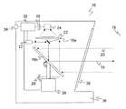
図1は、本発明によるレーザ・スキャナ10の概略断面図である。本発明をこの例に即して説明するが、本発明は、請求項に言及された特性を有する検出および距離測定用の他の光電センサも含んでいる。 FIG. 1 is a schematic cross-sectional view of a
例えばレーザである投光器12によって生成された、個別光パルスを有するビーム14は、光偏向部16a〜bを介して監視領域18内へと偏向され、そこで場合によっては存在する物体によって拡散反射される。窓ガラスのような、投光の一部を反射するとともに透過させる部分的に透明な物体による混濁や、多数の散乱標的による混濁の場合にそうであるように、拡散反射は繰り返し様々な距離において起こり得る。拡散反射光20は再びレーザ・スキャナに到達し、そこで偏向部16bを介し、受光光学系22を用いて、受光器24(例えばフォト・ダイオード)によって検出される。 A
光偏向部16bは一般に、モータ26の駆動によって連続的に回転される回転ミラーとして構成されている。代替として、投光器12を含む測定ヘッドを回転させてもよい。その都度の角度位置はエンコーダ28によって検出される。このように、ビーム14は回転動作によって生成された監視領域18を走査する。監視領域18からの反射光信号20が受光器24によって受信されると、偏向部16bの角度位置から、エンコーダ28を用いて監視領域18内の物体の角度姿勢が推測される。 In general, the
加えて、個別光パルスの、その投光から監視領域18内の物体に当たって反射した後に受光されるまでの伝播時間が算出される。光伝播時間から、光の速度を用いて、レーザ・スキャナ10から物体までの距離が推測される。この評価は、AD変換器30でサンプリングされた受光器24の受光信号に基づいて、評価部32により行われる。この目的のために、評価部はAD変換器30の他に、投光器12、モータ26、およびエンコーダ28と接続されている。このように、角度および距離を介して、監視領域18内の全ての物体の二次元の極座標系を利用することができる。加えて、評価部32は、後述の方法で監視領域18内の混濁を測定する。物体位置および混濁等の全測定値は、出力部34を介して出力することができる。上述の全ての機能部品は、光出口および光入口の領域にフロントガラス38を備えたハウジング36内に配置されている。 In addition, the propagation time of the individual light pulse from when it is projected until it hits an object in the
安全技術への応用では、評価部32は、検出された物体の位置を1つまたは複数の保護区域と比較する。評価部32のその複数の保護区域の形状は対応するパラメータによって設定または構成される。それにより、評価部32は、保護区域が侵犯されているか、つまりその中に許容されない物体があるか否かを検知し、その結果に応じて、本実施形態では安全出力部(OSSD、Output Signal Switching Device)として構成された出力34を切り替える。それによって、例えば、レーザ・スキャナ10によって監視される、接続された機械の緊急停止が作動する。このようなレーザ・スキャナは、導入部で述べた基準、およびそれに要求される措置を満たすことによって安全レーザ・スキャナとして構成されている。 In application to safety technology, the
レーザ・スキャナ10は、視野が制限された周囲条件下でも使用することができ、つまり屋外に対応している、あるいは汚染された環境に対して耐性がある。このような周囲環境における外乱源としては、雪、霧、雨、噴霧、埃、煙、煤煙、排ガス、フロントガラスおよび光学系の汚れ、または同様の影響が考えられ、これらを全て混濁として一括りにすることができる。混濁では、多数の小粒子が散乱の中心として様々な射程における信号成分の原因となり、この信号成分に、検知された物体からの、測定対象であるエコーが重畳される。 The
図2は、評価部32がデジタル曲線として評価する、サンプリングされた受光信号の例示的な強度推移を示している。まず、強度推移における光伝播時間測定のための参照として採用される、参照投光パルスの強力な信号ピーク(最大値)40が投光時点に生じる。センサ10からの退出の後、混濁に基づく幅広い混濁ピーク42が生じる。この混濁ピーク42に対して、監視領域18内の物体からの受光パルス44が重畳される。その受光時点tEが測定対象である。 FIG. 2 shows an example intensity transition of the sampled received light signal that the
ここで、評価部32は、混濁の度合を測定し、受光パルス44の位置を特定するという役割を有している。その際、混濁度を利用することによって、受光パルス44の位置特定を容易にし、重畳によって生じ得る受光パルス44のずれを修正する必要がある。 Here, the
この評価のために、予測される曲線形状に関する予備知識が与えられている。まず、受光パルス44のパルス波形は、投光パルス波形と一致していることから原理的に分かる。それにより、幅の広い混濁最大値42を受光パルス44から区別することができる。受光パルス44が重畳にもかかわらず非常に明確に形成されている図2の状況では、このパルス波形のみから受光パルスを検知することができる。 For this evaluation, prior knowledge about the predicted curve shape is given. First, the pulse waveform of the
混濁によって生成される信号成分の信号波形も分かっている。つまりこの信号波形は、受光光学系22の信号ダイナミクスを用いた投光パルスのパルス波形の畳み込みによって表される。ここで、信号ダイナミクスあるいは距離に応じた強度特性とは、拡散反射する平らな標的を検知するための、距離に応じた検出感度のことである。前述の通り、混濁を引き起こす粒子は、多数の散漫散乱の中心を形成し、それにより、そのような散漫散乱する標的を事実上あらゆる観察対象の射程において形成する。 The signal waveform of the signal component generated by turbidity is also known. That is, this signal waveform is represented by convolution of the pulse waveform of the light projection pulse using the signal dynamics of the light receiving
理想的な場合、信号ダイナミクスは、フロントガラス38のすぐ後方まで信号がほとんど生じず、フロントガラス38に当たった時の反射が可能な限り、測定可能な外乱信号を引き起こさないように構成される。それによれば、信号ダイナミクスは確実な測定の最大射程距離まで可能な限り一定であるべきである。最大射程距離の後方では、信号ダイナミクスは二次的に減少する。とりわけ受光光学系22の特性としての信号ダイナミクスは、例えば仕上段階においてティーチングし、評価部32に保存することができる。 In the ideal case, the signal dynamics are configured so that little signal is produced just behind the
図3は、混濁のみに基づいた、受光パルス44が無い例示的な強度推移を示している。信号ダイナミクスは混濁ピーク42の側部の挙動を決定する。側部の平坦域においては、設計努力により達成された信号ダイナミクスの一定の推移からの逸脱が生じ、さらに混濁の度合によっては、センサ10の受光パスにある不図示の増幅要素の飽和による効果が生じる。 FIG. 3 shows an exemplary intensity transition without the received
図4は比較として、より強い混濁の際の、混濁のみに基づいた強度推移を例示的に示している。この混濁に応じて、混濁ピークの幅がより広くなっている。 For comparison, FIG. 4 exemplarily shows the intensity transition based only on turbidity at the time of stronger turbidity. According to this turbidity, the width of the turbidity peak becomes wider.
ここで、図5の例示的な強度推移に示されたように、受光パルス44がより強い混濁に重畳されると、受光パルス44の位置を特定することが著しく困難になる。その上、受光時点が重畳によってずれることもあり得る。 Here, as shown in the exemplary intensity transition of FIG. 5, when the
評価部32は、受光パルス44の信号波形および混濁の際の信号推移に関する、自身の予備知識を利用する。これにより、評価部32はまず既知の信号ダイナミクスを用いて、混濁があるか否かを調べ、混濁があればその強度を確定する。この混濁測定は、各方向において、受光信号における物体の受光パルス44の有無を検査する度に行われる。これによって、一方では、混濁あるいは混濁から導出される視界についての追加的な測定値が角度毎にもたらされ、それを出力部34へ出力または表示することができる。他方では、物体距離が測定される元となる信号についての混濁の度合いが分かる。従って、計測された混濁と検出された物体との間の帰属性に誤差が生じる原因となり得る、時間的または場所的な食い違いが生じない。 The
混濁は、方向に応じて測定能力についての情報を与える。加えて、混濁は、サンプリングされる受光信号に適応したフィルタを用いるために、またはパラメータをそのようなフィルタに適応させるために利用される。センサ10は、悪天候などによって変化する周囲条件にこのように対応することによって、その利用可能性を向上させる。 Turbidity gives information about the measuring ability depending on the direction. In addition, turbidity is utilized to use a filter adapted to the received light signal to be sampled or to adapt the parameters to such a filter.
例えば、混濁が確定されなかった場合には、混濁の抑制のためのフィルタは使用されない。つまり、この状況では、抑制するべき混濁が存在せず、むしろフィルタがあると、誤って物体のエコーの信号成分を抑制してしまいかねない。 For example, when turbidity is not determined, a filter for suppressing turbidity is not used. In other words, in this situation, there is no turbidity to be suppressed, and if there is a filter, the signal component of the object echo may be erroneously suppressed.
簡略な実施形態では、混濁の検知の際に、その混濁に帰属するサンプリングされる受光信号に用いられるフィルタが予め設計される。また、複数の固定化されたフィルタを外乱の様々な種類、つまり、雪、雨、霧等に対して予め設計しておくことも考えられる。稼働中には、検出された混濁が分類され、対応するフィルタが用いられる。最後に、実際に計測された混濁に基づいてパラメータの設定を行うことができる1つまたは複数のフィルタを設計することも考えられる。最も簡略な場合は、フィルタリング対象であるサンプリングされた受光信号に存在する混濁の強度に応じてパラメータの尺度を調節するという方法である。 In a simple embodiment, when detecting turbidity, a filter used for a sampled received light signal belonging to the turbidity is designed in advance. It is also conceivable to design a plurality of fixed filters in advance for various types of disturbances, that is, snow, rain, fog, and the like. During operation, the detected turbidity is classified and a corresponding filter is used. Finally, it is also conceivable to design one or more filters that can set parameters based on the actually measured turbidity. In the simplest case, the parameter scale is adjusted according to the intensity of turbidity present in the sampled received light signal to be filtered.
フィルタはいずれにしても、混濁による信号成分の、信号ダイナミクスから分かる強度推移を抑制するために最適化される。加えて、受光パルス44の既知の信号波形を考慮し、受光パルス44が、フィルタリングによって少なくとも可能な限り変化されずにいるか、またはより強調されるようにすることができる。 In any case, the filter is optimized in order to suppress the intensity transition of the signal component due to turbidity, which is known from the signal dynamics. In addition, taking into account the known signal waveform of the received
図6は、様々な混濁46、およびそれによって方向に応じて制限された射程を有するセンサ10の監視領域18の概略平面図である。走査ビーム14、20の最大射程距離を含む、一種の有効監視領域48が生じている。それに対して、有効監視領域48は、混濁46のある領域ではより短い射程に限られている。有効監視領域48の内部では混濁46にもかかわらずなおも確実な距離測定が可能である。このため、混濁の度合が角度に応じて評価される。 FIG. 6 is a schematic plan view of the
安全技術への応用では、有効監視領域48により、安全技術的な停止が必要となる混濁46であるか否かを決定することができる。この目的のために、図6には不図示の保護区域が、全ての関連する角度について、減少した射程内にあるか否かが検査される。射程内にある場合は、混濁にもかかわらず安全性が引き続き保証される。そうでなければ、安全のための停止が行われる。 In the application to safety technology, the effective monitoring area 48 can determine whether or not the
Claims (12)
Translated fromJapanese投光ビーム(14)を投光するための投光器(12)と、前記監視領域(18)内で前記投光ビーム(14)を周期的に偏向させるための回転可能な偏向部(16)と、前記監視領域(18)内で拡散反射または反射されたビーム(20)から受光信号を生成するための受光器(24)と、前記受光信号をサンプリングするためのAD変換器(30)と、評価部(32)とを備え、
前記受光信号に基づいて、前記物体までの距離を光伝播時間法を用いて測定するとともに混濁度を測定する、光電センサにおいて、
前記評価部(32)が、前記混濁度を、前記投光ビーム(14)の方向における混濁について角度に応じて測定し、前記混濁度の測定の対象となった前記受光信号と同一の信号から距離を測定し、前記角度に応じた混濁度を距離測定の際に考慮するように構成されていることを特徴とする、光電センサ。A photoelectric sensor (10), in particular a laser scanner, for the detection and distance measurement of objects in the monitoring area (18),
A projector (12) for projecting the projection beam (14), and a rotatable deflector (16) for periodically deflecting the projection beam (14) in the monitoring area (18); A light receiver (24) for generating a light reception signal from the beam (20) diffusely reflected or reflected in the monitoring region (18), and an AD converter (30) for sampling the light reception signal; An evaluation unit (32),
In the photoelectric sensor for measuring the turbidity while measuring the distance to the object using the light propagation time method based on the received light signal,
The evaluation unit (32) measures the turbidity according to the angle with respect to turbidity in the direction of the projection beam (14), and from the same signal as the received light signal that is the target of the turbidity measurement. A photoelectric sensor configured to measure a distance and to take into account the turbidity corresponding to the angle when measuring the distance.
前記評価部(32)が、前記受光信号中の受光パルスに基づいて、前記投光ビーム(14)中にある物体に帰属する受光時点を検知する、請求項1に記載のセンサ(10)。The projector (12) projects a projection pulse having a certain projection pulse waveform at a certain projection time point,
The sensor (10) according to claim 1, wherein the evaluation unit (32) detects a light reception time point belonging to an object in the light projection beam (14) based on a light reception pulse in the light reception signal.
投光ビーム(14)が投光され、前記監視領域(18)内で周期的に偏向され、
受光信号が、前記監視領域(18)内で拡散反射または反射されたビーム(20)から生成およびサンプリングされ、前記受光信号に基づいて、前記物体までの距離が光伝播時間法を用いて測定されるとともに混濁度が測定される、方法において、
前記混濁度が、前記投光ビーム(14)の方向における混濁について角度に応じて測定され、前記混濁度の測定の対象となった前記受光信号と同一の信号から距離が測定され、前記角度に応じた混濁度が距離測定の際に考慮されることを特徴とする、方法。A method for the detection and distance measurement of an object in a monitoring area (18) comprising:
A projection beam (14) is projected and periodically deflected in the monitoring area (18),
A received light signal is generated and sampled from the diffusely reflected or reflected beam (20) in the monitoring region (18), and based on the received light signal, the distance to the object is measured using a light propagation time method. And the turbidity is measured,
The turbidity is measured according to the angle for turbidity in the direction of the projection beam (14), the distance is measured from the same signal as the received light signal that is the object of the turbidity measurement, and the angle is A method, characterized in that the corresponding turbidity is taken into account in the distance measurement.
Applications Claiming Priority (2)
| Application Number | Priority Date | Filing Date | Title |
|---|---|---|---|
| DE102012112987.8 | 2012-12-21 | ||
| DE201210112987DE102012112987B3 (en) | 2012-12-21 | 2012-12-21 | Optoelectronic sensor i.e. laser scanner, for detection and distance determination of static machine parts in monitored area, has evaluation unit determining object distance from signal by considering visibility measure and angle-dependence |
Publications (1)
| Publication Number | Publication Date |
|---|---|
| JP2014122891Atrue JP2014122891A (en) | 2014-07-03 |
Family
ID=49579777
Family Applications (1)
| Application Number | Title | Priority Date | Filing Date |
|---|---|---|---|
| JP2013260398APendingJP2014122891A (en) | 2012-12-21 | 2013-12-17 | Photoelectronic sensor and method for detecting object and measuring distance |
Country Status (2)
| Country | Link |
|---|---|
| JP (1) | JP2014122891A (en) |
| DE (1) | DE102012112987B3 (en) |
Cited By (2)
| Publication number | Priority date | Publication date | Assignee | Title |
|---|---|---|---|---|
| WO2016051861A1 (en)* | 2014-09-30 | 2016-04-07 | シャープ株式会社 | Obstacle determination device and obstacle determination method |
| CN113167858A (en)* | 2018-10-10 | 2021-07-23 | 科思创知识产权两合公司 | Surrounding sensor with movable deflection device for motor vehicle |
Families Citing this family (16)
| Publication number | Priority date | Publication date | Assignee | Title |
|---|---|---|---|---|
| EP2927711B1 (en)* | 2014-04-04 | 2016-03-30 | Sick Ag | Laser scanner and method for the reliable detection of objects |
| US9964437B2 (en) | 2016-05-03 | 2018-05-08 | Datalogic IP Tech, S.r.l. | Laser scanner with reduced internal optical reflection comprising a light detector disposed between an interference filter and a collecting mirror |
| US11585905B2 (en) | 2016-05-03 | 2023-02-21 | Datalogic Ip Tech S.R.L. | Laser scanner |
| US10048120B2 (en) | 2016-05-03 | 2018-08-14 | Datalogic IP Tech, S.r.l. | Laser scanner and optical system |
| US10061021B2 (en) | 2016-07-06 | 2018-08-28 | Datalogic IP Tech, S.r.l. | Clutter filter configuration for safety laser scanner |
| DE102016115201A1 (en) | 2016-08-16 | 2018-02-22 | Sick Ag | Method for operating a monitoring sensor and monitoring sensor |
| JP7076947B2 (en)* | 2017-03-31 | 2022-05-30 | 株式会社トプコン | Surveying equipment, surveying method and control program of surveying equipment |
| DE102017117162A1 (en) | 2017-07-28 | 2019-01-31 | Sick Ag | Sensor and method for detection and distance determination of objects |
| EP3588139B1 (en) | 2018-06-26 | 2020-06-03 | Sick Ag | Optoelectronic sensor and distance measurement method |
| DE102018127712A1 (en) | 2018-11-07 | 2020-05-07 | Valeo Schalter Und Sensoren Gmbh | Method for recognizing at least one tire track for a motor vehicle by means of an optoelectronic sensor, optoelectronic sensor and motor vehicle |
| DE102019107681B4 (en) | 2019-03-26 | 2022-12-01 | Sick Ag | Method for operating a distance measuring surveillance sensor and distance measuring surveillance sensor |
| EP3715908B1 (en)* | 2019-03-27 | 2024-11-20 | MicroVision, Inc. | Method and device for optically measuring distances |
| DE102020115252B4 (en) | 2020-06-09 | 2024-06-13 | Mercedes-Benz Group AG | Method and device for detecting contamination on a protective screen of a lidar sensor |
| DE102022129795A1 (en)* | 2022-11-10 | 2024-05-16 | Bayerische Motoren Werke Aktiengesellschaft | LIDAR SYSTEM AND METHOD FOR OPERATING A LIDAR SYSTEM |
| DE102022132310A1 (en)* | 2022-12-06 | 2024-06-06 | Sick Ag | Optoelectronic sensor and method for detecting and determining the distance of objects |
| DE102024104412A1 (en)* | 2024-02-16 | 2025-08-21 | Valeo Detection Systems GmbH | COMPUTER-IMPLEMENTED METHOD, ELECTRONIC VEHICLE SYSTEM AND COMPUTER PROGRAM PRODUCT |
Citations (5)
| Publication number | Priority date | Publication date | Assignee | Title |
|---|---|---|---|---|
| JPH06342071A (en)* | 1993-06-02 | 1994-12-13 | Nissan Motor Co Ltd | Distance-between-vehicles detection apparatus |
| JPH09159765A (en)* | 1995-12-08 | 1997-06-20 | Nissan Motor Co Ltd | Radar equipment for vehicles |
| JP2009110069A (en)* | 2007-10-26 | 2009-05-21 | Optex Co Ltd | Laser area sensor |
| JP2010181335A (en)* | 2009-02-06 | 2010-08-19 | Furuno Electric Co Ltd | Radar device |
| JP2011505545A (en)* | 2007-09-27 | 2011-02-24 | オムロン サイエンティフィック テクノロジーズ, インコーポレイテッド | Clutter removal in an active object detection system. |
Family Cites Families (6)
| Publication number | Priority date | Publication date | Assignee | Title |
|---|---|---|---|---|
| DE4340756C5 (en)* | 1992-12-08 | 2006-08-10 | Sick Ag | Laser range finding device |
| DE19717399C2 (en)* | 1997-04-24 | 2001-05-23 | Martin Spies | Device for determining the distance and type of objects and the visibility |
| DE10149768A1 (en)* | 2001-10-09 | 2003-04-17 | Ibeo Automobile Sensor Gmbh | Visibility determination |
| EP2182378B1 (en)* | 2008-10-30 | 2012-07-18 | Sick Ag | Laser scanner to measure distance |
| DE102009057104B4 (en)* | 2009-12-04 | 2014-05-28 | Sick Ag | Distance measuring laser scanner |
| EP2431766B1 (en)* | 2010-09-21 | 2013-01-23 | Sick Ag | Optical scanner with soiling detection |
- 2012
- 2012-12-21DEDE201210112987patent/DE102012112987B3/enactiveActive
- 2013
- 2013-12-17JPJP2013260398Apatent/JP2014122891A/enactivePending
Patent Citations (5)
| Publication number | Priority date | Publication date | Assignee | Title |
|---|---|---|---|---|
| JPH06342071A (en)* | 1993-06-02 | 1994-12-13 | Nissan Motor Co Ltd | Distance-between-vehicles detection apparatus |
| JPH09159765A (en)* | 1995-12-08 | 1997-06-20 | Nissan Motor Co Ltd | Radar equipment for vehicles |
| JP2011505545A (en)* | 2007-09-27 | 2011-02-24 | オムロン サイエンティフィック テクノロジーズ, インコーポレイテッド | Clutter removal in an active object detection system. |
| JP2009110069A (en)* | 2007-10-26 | 2009-05-21 | Optex Co Ltd | Laser area sensor |
| JP2010181335A (en)* | 2009-02-06 | 2010-08-19 | Furuno Electric Co Ltd | Radar device |
Cited By (4)
| Publication number | Priority date | Publication date | Assignee | Title |
|---|---|---|---|---|
| WO2016051861A1 (en)* | 2014-09-30 | 2016-04-07 | シャープ株式会社 | Obstacle determination device and obstacle determination method |
| CN113167858A (en)* | 2018-10-10 | 2021-07-23 | 科思创知识产权两合公司 | Surrounding sensor with movable deflection device for motor vehicle |
| JP2022504473A (en)* | 2018-10-10 | 2022-01-13 | コベストロ・インテレクチュアル・プロパティ・ゲゼルシャフト・ミット・ベシュレンクテル・ハフツング・アンド・コー・カーゲー | Peripheral sensor with movable deflection device for automobiles |
| JP7450614B2 (en) | 2018-10-10 | 2024-03-15 | コベストロ・インテレクチュアル・プロパティ・ゲゼルシャフト・ミット・ベシュレンクテル・ハフツング・アンド・コー・カーゲー | Ambient sensor with movable deflection device for automobiles |
Also Published As
| Publication number | Publication date |
|---|---|
| DE102012112987B3 (en) | 2013-12-05 |
Similar Documents
| Publication | Publication Date | Title |
|---|---|---|
| JP2014122891A (en) | Photoelectronic sensor and method for detecting object and measuring distance | |
| CA2934796C (en) | Surface defect detecting method and surface defect detecting apparatus | |
| US8902409B2 (en) | Optoelectric sensor and a method for the detection and distance determination of objects | |
| US9477007B2 (en) | Laser scanner | |
| US8520221B2 (en) | Optical sensor | |
| US20150323654A1 (en) | Distance-measuring sensor and method for detecting and determining the distance of objects | |
| JP2009516157A (en) | Spatial area monitoring apparatus and method | |
| CN108303690B (en) | Ranging method and ranging system for eliminating laser radar blind area | |
| AU2014384279B2 (en) | Method for detecting flaws in the walls of hollow glass items | |
| US20230213630A1 (en) | Method and device for identifying contamination on a protective screen of a lidar sensor | |
| US11567181B2 (en) | Method for detecting a functional impairment of a laser scanner, laser scanner, and motor vehicle | |
| US10877132B2 (en) | Method of operating a scanner and scanner | |
| CN113253291A (en) | Safety laser scanner and method for front panel monitoring | |
| JP2014137374A (en) | Distance measuring photoelectric sensor and object distance measuring method | |
| CN115407307A (en) | Lidar system and method for detecting contamination of a beam path of a lidar system | |
| US20210003676A1 (en) | System and method | |
| CN110346813B (en) | Pulsed light detection and ranging apparatus, system and method for detecting and ranging objects in pulsed light detection and ranging system | |
| US9140820B2 (en) | Optical sensor and test method for testing the operability of an optical sensor | |
| CN114859318A (en) | Lidar system with beam optical diagnostics | |
| KR101887477B1 (en) | Optical sensor system with guide light for safty and security system | |
| DE202012105044U1 (en) | Opto-electronic sensor for the detection and distance determination of objects | |
| JP6382899B2 (en) | Object detection method | |
| US20230036431A1 (en) | BLOOM COMPENSATION IN A LIGHT DETECTION AND RANGING (LiDAR) SYSTEM | |
| CN216792445U (en) | Photoelectric sensor for monitoring front window | |
| US11573308B2 (en) | Method of operating a distance-measuring monitoring sensor and distance measuring monitoring sensor |
Legal Events
| Date | Code | Title | Description |
|---|---|---|---|
| A977 | Report on retrieval | Free format text:JAPANESE INTERMEDIATE CODE: A971007 Effective date:20141023 | |
| A131 | Notification of reasons for refusal | Free format text:JAPANESE INTERMEDIATE CODE: A131 Effective date:20141028 | |
| A521 | Written amendment | Free format text:JAPANESE INTERMEDIATE CODE: A523 Effective date:20150114 | |
| A02 | Decision of refusal | Free format text:JAPANESE INTERMEDIATE CODE: A02 Effective date:20150630 | |
| A521 | Written amendment | Free format text:JAPANESE INTERMEDIATE CODE: A523 Effective date:20151005 | |
| A911 | Transfer to examiner for re-examination before appeal (zenchi) | Free format text:JAPANESE INTERMEDIATE CODE: A911 Effective date:20151013 | |
| A912 | Re-examination (zenchi) completed and case transferred to appeal board | Free format text:JAPANESE INTERMEDIATE CODE: A912 Effective date:20151204 | |
| A521 | Written amendment | Free format text:JAPANESE INTERMEDIATE CODE: A523 Effective date:20160915 |