JP2014115321A - Display device - Google Patents
Display deviceDownload PDFInfo
- Publication number
- JP2014115321A JP2014115321AJP2012267236AJP2012267236AJP2014115321AJP 2014115321 AJP2014115321 AJP 2014115321AJP 2012267236 AJP2012267236 AJP 2012267236AJP 2012267236 AJP2012267236 AJP 2012267236AJP 2014115321 AJP2014115321 AJP 2014115321A
- Authority
- JP
- Japan
- Prior art keywords
- display device
- surface portion
- touch sensor
- display
- cover glass
- Prior art date
- Legal status (The legal status is an assumption and is not a legal conclusion. Google has not performed a legal analysis and makes no representation as to the accuracy of the status listed.)
- Pending
Links
Images


Classifications
- G—PHYSICS
- G06—COMPUTING OR CALCULATING; COUNTING
- G06F—ELECTRIC DIGITAL DATA PROCESSING
- G06F1/00—Details not covered by groups G06F3/00 - G06F13/00 and G06F21/00
- G06F1/16—Constructional details or arrangements
- G06F1/1613—Constructional details or arrangements for portable computers
- G06F1/1633—Constructional details or arrangements of portable computers not specific to the type of enclosures covered by groups G06F1/1615 - G06F1/1626
- G06F1/1637—Details related to the display arrangement, including those related to the mounting of the display in the housing
- G06F1/1647—Details related to the display arrangement, including those related to the mounting of the display in the housing including at least an additional display
- G06F1/165—Details related to the display arrangement, including those related to the mounting of the display in the housing including at least an additional display the additional display being small, e.g. for presenting status information
- G—PHYSICS
- G06—COMPUTING OR CALCULATING; COUNTING
- G06F—ELECTRIC DIGITAL DATA PROCESSING
- G06F1/00—Details not covered by groups G06F3/00 - G06F13/00 and G06F21/00
- G06F1/16—Constructional details or arrangements
- G06F1/1613—Constructional details or arrangements for portable computers
- G06F1/1626—Constructional details or arrangements for portable computers with a single-body enclosure integrating a flat display, e.g. Personal Digital Assistants [PDAs]
- G—PHYSICS
- G06—COMPUTING OR CALCULATING; COUNTING
- G06F—ELECTRIC DIGITAL DATA PROCESSING
- G06F1/00—Details not covered by groups G06F3/00 - G06F13/00 and G06F21/00
- G06F1/16—Constructional details or arrangements
- G06F1/1613—Constructional details or arrangements for portable computers
- G06F1/1633—Constructional details or arrangements of portable computers not specific to the type of enclosures covered by groups G06F1/1615 - G06F1/1626
- G06F1/1684—Constructional details or arrangements related to integrated I/O peripherals not covered by groups G06F1/1635 - G06F1/1675
- G06F1/169—Constructional details or arrangements related to integrated I/O peripherals not covered by groups G06F1/1635 - G06F1/1675 the I/O peripheral being an integrated pointing device, e.g. trackball in the palm rest area, mini-joystick integrated between keyboard keys, touch pads or touch stripes
- G06F1/1692—Constructional details or arrangements related to integrated I/O peripherals not covered by groups G06F1/1635 - G06F1/1675 the I/O peripheral being an integrated pointing device, e.g. trackball in the palm rest area, mini-joystick integrated between keyboard keys, touch pads or touch stripes the I/O peripheral being a secondary touch screen used as control interface, e.g. virtual buttons or sliders
- G—PHYSICS
- G06—COMPUTING OR CALCULATING; COUNTING
- G06F—ELECTRIC DIGITAL DATA PROCESSING
- G06F3/00—Input arrangements for transferring data to be processed into a form capable of being handled by the computer; Output arrangements for transferring data from processing unit to output unit, e.g. interface arrangements
- G06F3/01—Input arrangements or combined input and output arrangements for interaction between user and computer
- G06F3/03—Arrangements for converting the position or the displacement of a member into a coded form
- G06F3/041—Digitisers, e.g. for touch screens or touch pads, characterised by the transducing means
- G06F3/0412—Digitisers structurally integrated in a display
- G—PHYSICS
- G06—COMPUTING OR CALCULATING; COUNTING
- G06F—ELECTRIC DIGITAL DATA PROCESSING
- G06F3/00—Input arrangements for transferring data to be processed into a form capable of being handled by the computer; Output arrangements for transferring data from processing unit to output unit, e.g. interface arrangements
- G06F3/01—Input arrangements or combined input and output arrangements for interaction between user and computer
- G06F3/03—Arrangements for converting the position or the displacement of a member into a coded form
- G06F3/041—Digitisers, e.g. for touch screens or touch pads, characterised by the transducing means
- G06F3/0416—Control or interface arrangements specially adapted for digitisers
- G—PHYSICS
- G06—COMPUTING OR CALCULATING; COUNTING
- G06F—ELECTRIC DIGITAL DATA PROCESSING
- G06F2203/00—Indexing scheme relating to G06F3/00 - G06F3/048
- G06F2203/033—Indexing scheme relating to G06F3/033
- G06F2203/0339—Touch strips, e.g. orthogonal touch strips to control cursor movement or scrolling; single touch strip to adjust parameter or to implement a row of soft keys
Landscapes
- Engineering & Computer Science (AREA)
- Theoretical Computer Science (AREA)
- General Engineering & Computer Science (AREA)
- Computer Hardware Design (AREA)
- Human Computer Interaction (AREA)
- Physics & Mathematics (AREA)
- General Physics & Mathematics (AREA)
- Devices For Indicating Variable Information By Combining Individual Elements (AREA)
- Microelectronics & Electronic Packaging (AREA)
- Position Input By Displaying (AREA)
Abstract
Translated fromJapaneseDescription
Translated fromJapanese本発明は、表示装置に関する。 The present invention relates to a display device.
近年、ユーザーが多様な入力操作を容易に行い得る表示装置として、タッチセンサを備える表示装置が提案されている。例えば特許文献1には、主面に表示画面を有すると共に、複数の側面にタッチセンサを有する矩形板状の表示装置が記載されている。特許文献1に記載の表示装置では、側面のタッチセンサ上を、操作者の指が長さ方向または幅方向に沿って動いた際に所定の入力がなされる。 In recent years, a display device including a touch sensor has been proposed as a display device that allows a user to easily perform various input operations. For example,
近年、ユーザーがより多様な入力操作を行い得る表示装置に対する要望が高まってきている。 In recent years, there has been an increasing demand for display devices that allow users to perform various input operations.
本発明の主な目的は、ユーザーが多様な入力操作を行い得る表示装置を提供することにある。 A main object of the present invention is to provide a display device that allows a user to perform various input operations.
本発明に係る表示装置は、装置本体と、カバーガラスとを備える。装置本体は、主面と、第1の側面と、第2の側面とを有する。主面は、互いに直交する第1及び第2の方向に沿って延びる。第1の側面は、主面の第1の方向の一方側に位置する。第2の側面は、主面の第1の方向の他方側に位置する。カバーガラスは、前面部と、第1の側面部とを有する。前面部は、主面を覆う。第1の側面部は、第1の側面を覆う。装置本体は、表示部と、第2のタッチセンサ面とを有する。表示部は、主面に設けられている。表示部は、第1のタッチセンサ面を構成している。第2のタッチセンサ面は、第1の側面に設けられている。第1の側面部の少なくとも前面部との接続部の外表面が曲面により構成されている。 The display device according to the present invention includes a device main body and a cover glass. The apparatus main body has a main surface, a first side surface, and a second side surface. The main surface extends along first and second directions orthogonal to each other. The first side surface is located on one side of the main surface in the first direction. The second side surface is located on the other side of the main surface in the first direction. The cover glass has a front surface portion and a first side surface portion. The front portion covers the main surface. The first side surface portion covers the first side surface. The apparatus main body includes a display unit and a second touch sensor surface. The display unit is provided on the main surface. The display unit constitutes a first touch sensor surface. The second touch sensor surface is provided on the first side surface. The outer surface of the connection portion between at least the front surface portion of the first side surface portion is formed by a curved surface.
本発明に係る表示装置は、前面部上から第1の側面部上へ、または第1の側面部上から前面部上へと、物体がカバーガラスに触れながら移動した際に、第1の操作が入力されるものであってもよい。 The display device according to the present invention performs the first operation when an object moves while touching the cover glass from the front surface portion to the first side surface portion or from the first side surface portion to the front surface portion. May be input.
本発明に係る表示装置は、第1の側面部上を、物体がカバーガラスに触れながら第2の方向に沿って移動した際に、第2の操作が入力されるものであってもよい。 The display device according to the present invention may be one in which the second operation is input when the object moves along the second direction while touching the cover glass on the first side surface portion.
本発明に係る表示装置は、物体が第1の側面部の一領域に触れた際に、第3の操作が入力されるものであってもよい。 The display device according to the present invention may be one in which a third operation is input when an object touches an area of the first side surface portion.
第1のタッチセンサ面と第2のタッチセンサ面とが連続して設けられていてもよい。 The first touch sensor surface and the second touch sensor surface may be provided continuously.
前面部と第1の側面部とのなす角の大きさが90°以上であってもよい。 The angle formed by the front surface portion and the first side surface portion may be 90 ° or more.
カバーガラスは、前面部において装置本体と固定されていることが好ましい。 It is preferable that the cover glass is fixed to the apparatus main body at the front surface portion.
表示部は、第2の方向に沿って設けられた複数の表示領域を有していてもよい。その場合、複数の表示領域は、それぞれ、第1の側面部のうち、当該表示領域の第1の方向における一方側に位置する領域に物体を接触させることにより操作可能であることが好ましい。 The display unit may have a plurality of display areas provided along the second direction. In that case, it is preferable that each of the plurality of display areas can be operated by bringing an object into contact with an area located on one side of the first side surface portion in the first direction of the display area.
装置本体は、第2の側面に位置する第3のタッチセンサ面をさらに有していてもよい。その場合、カバーガラスは、第2の側面を覆う第2の側面部をさらに有することが好ましい。第2の側面部の少なくとも前面部との接続部の外表面が曲面により構成されていることが好ましい。 The apparatus main body may further include a third touch sensor surface located on the second side surface. In that case, it is preferable that a cover glass further has a 2nd side part which covers a 2nd side surface. It is preferable that the outer surface of the connection portion between at least the front surface portion of the second side surface portion is constituted by a curved surface.
本発明に係る表示装置は、モバイル表示装置であることが好ましい。 The display device according to the present invention is preferably a mobile display device.
本発明によれば、ユーザーが多様な入力操作を行い得る表示装置を提供することができる。 According to the present invention, it is possible to provide a display device that allows a user to perform various input operations.
以下、本発明を実施した好ましい形態の一例について説明する。但し、下記の実施形態は、単なる例示である。本発明は、下記の実施形態に何ら限定されない。 Hereinafter, an example of the preferable form which implemented this invention is demonstrated. However, the following embodiment is merely an example. The present invention is not limited to the following embodiments.
また、実施形態等において参照する各図面において、実質的に同一の機能を有する部材は同一の符号で参照することとする。また、実施形態等において参照する図面は、模式的に記載されたものである。図面に描画された物体の寸法の比率などは、現実の物体の寸法の比率などとは異なる場合がある。図面相互間においても、物体の寸法比率等が異なる場合がある。具体的な物体の寸法比率等は、以下の説明を参酌して判断されるべきである。 Moreover, in each drawing referred in embodiment etc., the member which has a substantially the same function shall be referred with the same code | symbol. The drawings referred to in the embodiments and the like are schematically described. A ratio of dimensions of an object drawn in a drawing may be different from a ratio of dimensions of an actual object. The dimensional ratio of the object may be different between the drawings. The specific dimensional ratio of the object should be determined in consideration of the following description.
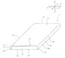
図1は、本実施形態に係る表示装置1の模式的斜視図である。表示装置1は、例えば、据え置き型の表示装置であってもよいが、携帯電話、スマートフォン、タブレットパーソナルコンピューター(タブレットPC)、ノート型パーソナルコンピューター等のモバイル表示装置であることが好ましい。 FIG. 1 is a schematic perspective view of a
表示装置1は、装置本体20と、カバーガラス10とを備える。 The
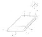
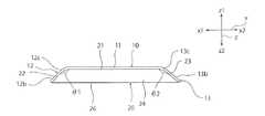
図2及び図3に示されるように、装置本体20は、板状に設けられている。装置本体20は、第1の主面21と、第2の主面26と、第1〜第4の側面22〜25とを有する。第1及び第2の主面21,26は、互いに直行するx軸方向及びy軸方向に沿って延びている。第1及び第2の主面21,26は、それぞれ、実質的に平面状である。第1の主面21と第2の主面26とは、x軸方向及びy軸方向に対して垂直なz軸方向において対向している。 As shown in FIGS. 2 and 3, the apparatus
第1の側面22は、主面21,26のx軸方向のx1側に位置している。第1の側面22は、第1の主面21と第2の主面26とを接続している。第2の側面23は、主面21,26のx軸方向のx2側に位置している。第2の側面23は、第1の主面21と第2の主面26とを接続している。第3の側面24は、主面21,26のy軸方向の一方側に位置している一方、第4の側面25は、主面21,26のy軸方向の他方側に位置している。第3及び第4の側面24,25は、それぞれ、第1の主面21と第2の主面26とを接続している。 The
第1の主面21には、文字や画像などを表示させる表示部21aが設けられている。表示部21aは、第1のタッチセンサ面を構成している。ここで、「タッチセンサ面」とは、操作者の指やタッチペンなどの物体が接触することが検知される面のことである。タッチセンサ面は、静電容量式、感圧式、光学式等のタッチセンサ面であってもよい。 The first
図3に示されるように、第1の側面22には、第2のタッチセンサ面22aが設けられている。第2のタッチセンサ面22aは、長手方向がy軸方向に沿って延びる細長形状を有する。具体的には、第2のタッチセンサ面22aは、長手方向がy軸方向に沿って延びる矩形状に設けられている。第1の側面22の第1の主面21との接続部の外表面は曲面により構成されており、その他の部分の外表面は平面により構成されている。すなわち、第1の側面22と第1の主面21とにより構成される稜線部は、丸められた形状を有する。 As shown in FIG. 3, the
第2の側面23には、第3のタッチセンサ面23aが設けられている。第3のタッチセンサ面23aは、長手方向がy軸方向に沿って延びる細長形状を有する。具体的には、第3のタッチセンサ面23aは、長手方向がy軸方向に沿って延びる矩形状に設けられている。第2の側面23の第1の主面21との接続部の外表面は曲面により構成されており、その他の部分の外表面は平面により構成されている。すなわち、第2の側面23と第1の主面21とにより構成される稜線部は、丸められた形状を有する。 A third
本実施形態では、第3及び第4の側面24,25にはタッチセンサ面が設けられていないが、第3及び第4の側面にもタッチセンサ面が設けられていてもよい。 In the present embodiment, the touch sensor surfaces are not provided on the third and fourth side surfaces 24 and 25, but the touch sensor surfaces may also be provided on the third and fourth side surfaces.
図1に示されるように、装置本体20の第1の主面21並びに第1及び第2の側面22,23は、カバーガラス10により覆われている。カバーガラス10は、前面部11と、第1の側面部12と、第2の側面部13とを有する。前面部11並びに第1の側面部12及び第2の側面部13は、一体に設けられている。すなわち、カバーガラス10は、一枚のガラス板により構成されている。 As shown in FIG. 1, the first
前面部11は、第1の主面21の少なくとも表示部21aが設けられた領域を覆っている。具体的には、本実施形態では、前面部11は、第1の主面21の実質的に全体を覆っている。前面部11は、実質的に平板状に設けられている。前面部11の平面形状は、x軸方向と短辺とが平行で、y軸方向と長辺とが平行な矩形である。 The
前面部11のx軸方向のx1側端部には、第1の側面部12が接続されている。第1の側面部12は、装置本体20の第1の側面22の少なくとも一部を覆っている。具体的には、本実施形態では、第1の側面部12は、第1の側面22の実質的に全体を覆っている。第1の側面部12は、屈曲部12cと、平面部12bとを有する。屈曲部12cは、第1の側面部12の前面部11との接続部により構成されている。屈曲部12cの外表面(装置本体20とは反対側の表面)は、曲面により構成されている。具体的には、本実施形態では、屈曲部12cの外表面と内表面とのそれぞれが曲面により構成されている。もっとも、屈曲部12cの内表面は、少なくともひとつの平面により構成されていてもよい。 A first
平面部12bは、屈曲部12cに接続されている。平面部12bは、第1の側面22のz方向におけるz2側端部にまで至っている。 The
前面部11のx軸方向のx2側端部には、第2の側面部13が接続されている。第2の側面部13は、装置本体20の第2の側面23の少なくとも一部を覆っている。具体的には、本実施形態では、第2の側面部13は、第2の側面23の実質的に全体を覆っている。第2の側面部13は、屈曲部13cと、平面部13bとを有する。屈曲部13cは、第2の側面部13の前面部11との接続部により構成されている。屈曲部13cの外表面(装置本体20とは反対側の表面)は、曲面により構成されている。具体的には、本実施形態では、屈曲部13cの外表面と内表面とのそれぞれが曲面により構成されている。もっとも、屈曲部13cの内表面は、少なくともひとつの平面により構成されていてもよい。 A second
本実施形態において、カバーガラス10は、前面部11において装置本体20と固定されており、第1及び第2の側面部12,13は、装置本体20に直接固定されていない。もっとも、カバーガラス10は、前面部11のみならず、側面部12,13においても装置本体20に直接固定されていてもよい。なお、前面部11と装置本体20との固定は、例えば、接着剤等を用いて行うことができる。 In the present embodiment, the
次に、表示装置1の操作について説明する。表示装置1は、第1のタッチセンサ面を構成している表示部21aをタッチ操作することに加え、第2及び第3のタッチセンサ面22a、23aをタッチ操作することによっても操作可能である。 Next, the operation of the
(第1の操作)
例えば図4及び図5に示される矢印A1,A2のように、前面部11上から第1の側面部12上へ、または第1の側面部12上から前面部11上へと、物体(操作者の指や、タッチペンなど)がカバーガラス10に触れながら移動した際に、第1−1の操作が入力される。(First operation)
For example, as indicated by arrows A1 and A2 shown in FIGS. 4 and 5, an object (manipulation operation) is performed from the
同様に、例えば矢印A3,A4のように、前面部11上から第2の側面部13上へ、または第2の側面部13上から前面部11上へと、物体がカバーガラス10に触れながら移動した際に、第1−2の操作が入力される。 Similarly, for example, as indicated by arrows A3 and A4, an object touches the
(第2の操作)
例えば図5に示される矢印B1,B2のように、第1の側面部12上を、物体がカバーガラス10に触れながらy軸方向に沿って移動した際に、第2−1の操作が入力される。矢印B1のようにある物体が移動するとともに、矢印B2のように他の物体が移動したときには、第2−2の操作が入力される。(Second operation)
For example, as indicated by arrows B1 and B2 shown in FIG. 5, when the object moves along the y-axis direction while touching the
同様に、例えば矢印B3,B4のように、第2の側面部13上を、物体がカバーガラス10に触れながらy軸方向に沿って移動した際に、第2−3の操作が入力される。矢印B3のようにある物体が移動するとともに、矢印B4のように他の物体が移動したときには、第2−4の操作が入力される。 Similarly, as indicated by arrows B3 and B4, when the object moves along the y-axis direction while touching the
(第3の操作)
第1の側面部12の一領域に物体が触れた際に、第3−1の操作が入力される。(Third operation)
When an object touches an area of the first
同様に、第2の側面部13の一領域に物体が触れた際に、第3−2の操作が入力される。 Similarly, when an object touches an area of the second
なお、第1−1,1−2,2−1〜2−4,3−1,3−2の操作は、それぞれ同じ種類の操作であってもよいし、異なる種類の操作であってもよい。例えば、第1−1,第1−2の操作は、表示部21aに表示された画像のx軸方向のスクロールであってもよい。例えば、第2−1,2−3の操作は、表示部21aに表示された画像のy軸方向のスクロールであってもよい。例えば、第2−2,2−4の操作は、表示部21aに表示された画像の変倍(拡大または縮小)であってもよい。例えば、第3−1,3−2の操作は、表示部21aに表示された画面の切り替えであってもよい。 The operations of 1-1, 1-2, 2-1 to 2-4, 3-1, 3-2 may be the same type of operation, or may be different types of operations. Good. For example, the 1-1 and 1-2 operations may be scrolling in the x-axis direction of the image displayed on the
ところで、一般的に、表示装置では、側面部は平板状に設けられている。また、表示装置には、薄型化の要望が強いため、側面部は、幅狭である。従って、一般的な表示装置においては、側面にタッチセンサ面が設けられていたとしても、長さ方向または幅方向に沿って物体を移動させる操作と、一領域に物体を接触させる操作との、大別して2種類の操作しか行うことができない。幅狭な側面部上を厚み方向に沿って物体を移動させる操作を行うことは困難である。 By the way, generally, in the display device, the side surface portion is provided in a flat plate shape. In addition, since there is a strong demand for a thin display device, the side surface portion is narrow. Therefore, in a general display device, even if the touch sensor surface is provided on the side surface, an operation of moving the object along the length direction or the width direction and an operation of bringing the object into contact with one region, Broadly speaking, only two types of operations can be performed. It is difficult to perform an operation of moving an object along the thickness direction on a narrow side surface.
それに対して、表示装置1では、第1の側面部12の少なくとも前面部11との接続部である屈曲部12cの外表面が曲面により構成されている。このため、前面部11上から第1の側面部12上へと物体をなめらかに移動させることができるので、矢印A1や矢印A2のように物体を移動させる操作を行うことができる。すなわち、表示装置1では、第2の操作及び第3の操作に加えて、第1−1の操作を行い得る。従って、表示装置1のユーザーは、表示装置1に対して3種類以上の多様な入力操作を行い得る。 On the other hand, in the
さらに、表示装置1では、第2の側面部13の少なくとも前面部11との接続部である屈曲部13cの外表面が曲面により構成されている。このため、矢印A3や矢印A4のように物体を移動させる操作を行うことができる。よって、第1−2の操作も行い得る。従って、表示装置1のユーザーは、より多様な入力操作を表示装置1に対して行い得る。 Further, in the
さらに、側面部12,13を操作する場合、表示部21aに表示された画像が物体によって隠蔽されにくい。このため、表示装置1のように、側面部12,13における入力操作を多様化させることにより、表示部21aに表示された画像を視認可能な状態にしつつ、種々の操作を行うことが可能となる。 Furthermore, when the side surfaces 12 and 13 are operated, the image displayed on the
また、側面部が平板状である場合と比較して、側面部12,13の表面上におけるx軸方向に沿った幅寸法が大きく、側面部12,13の面積が広い。よって、矢印A1〜A4,B1〜B4に沿って物体を移動させやすい。従って、表示装置1では、操作が容易である。 Moreover, compared with the case where a side part is flat form, the width dimension along the x-axis direction on the surface of the
上述のように、表示装置には、薄型であることが求められる。このため、側面は幅狭である。この幅狭の側面のタッチセンサ面が設けられた領域の上に、個別のガラス板や樹脂板を固定することは困難である。また、タッチセンサ面は、指やタッチペンなどの物体によって押圧されるため、ガラス板や樹脂板を強固に固定する必要があるため、固定具を強固なものとする必要がある。よって、筐体が大型化しやすく、表示装置を小型化・薄型化することが困難である。表示装置の厚みが非常に薄い場合は、ガラス板や樹脂板を固定することができない場合もある。 As described above, the display device is required to be thin. For this reason, the side surface is narrow. It is difficult to fix individual glass plates or resin plates on the area where the narrow side touch sensor surface is provided. Further, since the touch sensor surface is pressed by an object such as a finger or a touch pen, it is necessary to firmly fix the glass plate or the resin plate, and thus it is necessary to make the fixing tool strong. Therefore, the casing is likely to be large, and it is difficult to reduce the size and thickness of the display device. When the thickness of the display device is very thin, the glass plate or the resin plate may not be fixed.
それに対して表示装置1では、前面部11と側面部12,13とが一体に設けられている。従って、前面部11と装置本体20とを固定しておけば、側面部12,13と装置本体20とを直接固定する必要は必ずしもない。従って、側面部12,13のz軸方向に沿った寸法が小さい場合であっても、側面部12,13を装置本体20に対して強固に固定することができる。その結果、表示装置1の薄型化・小型化を図ることができる。 On the other hand, in the
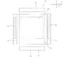
図6は、表示装置1の表示態様の一例を説明するための模式的平面図である。図6に示されるように、表示部21aは、y軸方向に沿って設けられた複数の表示領域21a1〜21a3を有する。これら複数の表示領域21a1〜21a3は、それぞれ別個の画像を表示可能である。複数の表示領域21a1〜21a3は、それぞれ、側面部12,13のうち、当該表示領域21a1〜21a3のx軸方向における一方側または他方側に位置する領域に物体を接触させることにより操作可能である。具体的には、表示領域21a1は、側面部12のうち、表示領域21a1のx軸方向におけるx1側に位置する領域D1−1と、側面部13のうち、表示領域21a1のx軸方向におけるx2側に位置する領域D1−2とのうちの少なくとも一方と表示部21aとに跨がって矢印A1〜A4のいずれかに沿って物体を移動させることにより操作可能である。表示領域21a2は、側面部12のうち、表示領域21a2のx軸方向におけるx1側に位置する領域D2−1と、側面部13のうち、表示領域21a2のx軸方向におけるx2側に位置する領域D2−2とのうちの少なくとも一方と表示部21aとに跨がって矢印A1〜A4のいずれかに沿って物体を移動させることにより操作可能である。表示領域21a3は、側面部12のうち、表示領域21a3のx軸方向におけるx1側に位置する領域D3−1と、側面部13のうち、表示領域21a3のx軸方向におけるx2側に位置する領域D3−2とのうちの少なくとも一方と表示部21aとに跨がって矢印A1〜A4のいずれかに沿って物体を移動させることにより操作可能である。 FIG. 6 is a schematic plan view for explaining an example of a display mode of the
従って、表示装置1では、複数の表示領域を、物体により隠蔽されることなく、別個に容易に操作可能である。 Therefore, in the
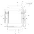
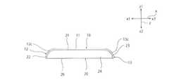
なお、本実施形態では、前面部11と第1の側面部12とのなす角の大きさθ1と、前面部11と第2の側面部13とのなす角の大きさθ2とが、約90°である例について説明したが、図7に示すように、θ1、θ2は、90°以上であってもよい。その場合、矢印A1〜A4に沿った操作をより容易に行うことができる。矢印A1〜A4に沿った操作をさらに容易にする観点からは、θ1、θ2は、それぞれ、90°以上であることが好ましく、90°より大きなことがさらに好ましく、100°以上であることがなお好ましい。但し、θ1、θ2が大きすぎると、表示装置1が大型化する傾向にある。従って、θ1、θ2は、それぞれ、175°以下であることが好ましく、170°以下であることがより好ましい。 In the present embodiment, the angle θ1 formed by the
本実施形態では、側面部12,13が屈曲部12c、13cに加えて平面部12b、13bを有する例について説明した。但し、本発明は、この構成に限定されない。例えば、図8に示されるように、側面部12,13が屈曲部12c、13cのみにより構成されていてもよい。 In the present embodiment, the example in which the
本実施形態では、第1のタッチセンサ面を構成している表示部21aと、第2のタッチセンサ面22aと、第3のタッチセンサ面23aとがそれぞれ別個に設けられている例について説明した。但し、本発明は、この構成に限定されない。例えば、図9に示されるように、表示部21aと、第2のタッチセンサ面22aと、第3のタッチセンサ面23aとが一体に設けられていてもよい。 In the present embodiment, an example in which the
本実施形態では、カバーガラス10が装置本体20の長辺側の側面22,23を覆うように設けられている例について説明した。但し、本発明は、この構成に限定されない。例えば、カバーガラスは、装置本体の短辺側の側面を覆うように設けられていてもよい。 In the present embodiment, the example in which the
カバーガラス10は、肉厚が薄くても高強度を保てる観点からは、強化ガラスであることが好ましい。 The
側面部12,13の内側に、LEDなどにより構成された表示灯がさらに設けられていてもよい。 Inside the
1…表示装置
10…カバーガラス
11…前面部
12…第1の側面部
12b…平面部
12c…屈曲部
13…第2の側面部
13b…平面部
13c…屈曲部
20…装置本体
21…第1の主面
21a…表示部
21a1〜21a3…表示領域
22…第1の側面
22a…第2のタッチセンサ面
23…第2の側面
23a…第3のタッチセンサ面
24…第3の側面
25…第4の側面
26…第2の主面DESCRIPTION OF
Claims (10)
Translated fromJapanese前記主面を覆う前面部と、前記第1の側面を覆う第1の側面部とを有するカバーガラスと、
を備え、
前記装置本体は、
前記主面に設けられており、第1のタッチセンサ面を構成している表示部と、
前記第1の側面に設けられた第2のタッチセンサ面と、
を有し、
前記第1の側面部の少なくとも前記前面部との接続部の外表面が曲面により構成されている、表示装置。A main surface extending along first and second directions orthogonal to each other; a first side surface located on one side of the first direction of the main surface; and the other of the main surface in the first direction. A device body having a second side surface located on the side;
A cover glass having a front surface portion covering the main surface and a first side surface portion covering the first side surface;
With
The apparatus main body is
A display unit provided on the main surface and constituting a first touch sensor surface;
A second touch sensor surface provided on the first side surface;
Have
The display device, wherein an outer surface of a connection portion between at least the first side surface portion and the front surface portion is configured by a curved surface.
前記複数の表示領域は、それぞれ、前記第1の側面部のうち、当該表示領域の前記第1の方向における一方側に位置する領域に物体を接触させることにより操作可能である、請求項1〜7のいずれか一項に記載の表示装置。The display unit has a plurality of display areas provided along the second direction,
Each of the plurality of display areas can be operated by bringing an object into contact with an area located on one side of the display area in the first direction of the first side surface portion. The display device according to claim 7.
前記カバーガラスは、前記第2の側面を覆う第2の側面部をさらに有し、
前記第2の側面部の少なくとも前記前面部との接続部の外表面が曲面により構成されている、請求項1〜8のいずれか一項に記載の表示装置。The apparatus main body further includes a third touch sensor surface located on the second side surface,
The cover glass further includes a second side surface portion covering the second side surface,
The display device according to any one of claims 1 to 8, wherein an outer surface of a connection portion between at least the second side surface portion and the front surface portion is formed by a curved surface.
Priority Applications (7)
| Application Number | Priority Date | Filing Date | Title |
|---|---|---|---|
| JP2012267236AJP2014115321A (en) | 2012-12-06 | 2012-12-06 | Display device |
| CN201380060327.1ACN104798017A (en) | 2012-12-06 | 2013-10-25 | Display device |
| US14/435,475US20150261255A1 (en) | 2012-12-06 | 2013-10-25 | Display device |
| EP13860662.9AEP2930594A4 (en) | 2012-12-06 | 2013-10-25 | DISPLAY DEVICE |
| PCT/JP2013/079000WO2014087758A1 (en) | 2012-12-06 | 2013-10-25 | Display device |
| KR1020157010286AKR20150093147A (en) | 2012-12-06 | 2013-10-25 | Display device |
| TW102141758ATWI578199B (en) | 2012-12-06 | 2013-11-15 | Display device |
Applications Claiming Priority (1)
| Application Number | Priority Date | Filing Date | Title |
|---|---|---|---|
| JP2012267236AJP2014115321A (en) | 2012-12-06 | 2012-12-06 | Display device |
Publications (1)
| Publication Number | Publication Date |
|---|---|
| JP2014115321Atrue JP2014115321A (en) | 2014-06-26 |
Family
ID=50883185
Family Applications (1)
| Application Number | Title | Priority Date | Filing Date |
|---|---|---|---|
| JP2012267236APendingJP2014115321A (en) | 2012-12-06 | 2012-12-06 | Display device |
Country Status (7)
| Country | Link |
|---|---|
| US (1) | US20150261255A1 (en) |
| EP (1) | EP2930594A4 (en) |
| JP (1) | JP2014115321A (en) |
| KR (1) | KR20150093147A (en) |
| CN (1) | CN104798017A (en) |
| TW (1) | TWI578199B (en) |
| WO (1) | WO2014087758A1 (en) |
Cited By (1)
| Publication number | Priority date | Publication date | Assignee | Title |
|---|---|---|---|---|
| JP2019220214A (en)* | 2014-11-26 | 2019-12-26 | 三星ディスプレイ株式會社Samsung Display Co.,Ltd. | Display device including touch sensor |
Families Citing this family (8)
| Publication number | Priority date | Publication date | Assignee | Title |
|---|---|---|---|---|
| CN104363730A (en)* | 2014-11-25 | 2015-02-18 | 深圳市华星光电技术有限公司 | Glass cover plate structure |
| CN106325749A (en)* | 2016-08-25 | 2017-01-11 | 维沃移动通信有限公司 | Operation method of mobile terminal, and mobile terminal |
| JP6819216B2 (en)* | 2016-10-26 | 2021-01-27 | セイコーエプソン株式会社 | Gyro sensor, manufacturing method of gyro sensor, electronic device and mobile body |
| KR102645631B1 (en)* | 2016-11-22 | 2024-03-08 | 삼성디스플레이 주식회사 | Bended display device |
| CN110494824B (en)* | 2017-08-21 | 2024-01-16 | 株式会社村田制作所 | Press sensors and electronics |
| KR102393175B1 (en)* | 2017-09-25 | 2022-05-02 | 엘지전자 주식회사 | Display device |
| CN112764586A (en) | 2021-01-28 | 2021-05-07 | 深圳市华星光电半导体显示技术有限公司 | Display device |
| KR20230022009A (en)* | 2021-08-06 | 2023-02-14 | 동우 화인켐 주식회사 | Touch Sensor |
Citations (8)
| Publication number | Priority date | Publication date | Assignee | Title |
|---|---|---|---|---|
| JPH05233085A (en)* | 1991-11-26 | 1993-09-10 | Itu Res Inc | Input device for contact control |
| JP2007072902A (en)* | 2005-09-08 | 2007-03-22 | Sony Corp | Input device, its manufacturing method, and electronic device |
| JP2009230341A (en)* | 2008-03-21 | 2009-10-08 | Epson Imaging Devices Corp | Input device, electro-optical device, and electronic appliance |
| JP2010117842A (en)* | 2008-11-12 | 2010-05-27 | Sharp Corp | Mobile information terminal |
| JP2010146418A (en)* | 2008-12-21 | 2010-07-01 | Alpine Electronics Inc | Touch panel corresponding to narrow frame lcd |
| JP2010231653A (en)* | 2009-03-27 | 2010-10-14 | Softbank Mobile Corp | Display device, display method, and program |
| JP2010262557A (en)* | 2009-05-11 | 2010-11-18 | Sony Corp | Information processing apparatus and method |
| WO2012132846A1 (en)* | 2011-03-31 | 2012-10-04 | 日本写真印刷株式会社 | Electrostatic capacitive touch screen |
Family Cites Families (8)
| Publication number | Priority date | Publication date | Assignee | Title |
|---|---|---|---|---|
| WO2010007813A1 (en) | 2008-07-16 | 2010-01-21 | 株式会社ソニー・コンピュータエンタテインメント | Mobile type image display device, method for controlling the same and information memory medium |
| US20130088450A1 (en)* | 2010-04-09 | 2013-04-11 | Sony Computer Entertainment Inc. | Information processing system, operation input device, information processing device, information processing method, program, and information storage medium |
| US8603574B2 (en)* | 2010-11-05 | 2013-12-10 | Apple Inc. | Curved touch sensor |
| JP5656661B2 (en)* | 2011-01-18 | 2015-01-21 | 京セラ株式会社 | Portable electronic devices |
| CN102654799A (en)* | 2011-03-04 | 2012-09-05 | 中兴通讯股份有限公司 | Method for controlling display screen of mobile terminal and mobile terminal |
| CN102209128B (en)* | 2011-05-04 | 2015-05-13 | 候万春 | Four-sided touch screen mobile phone terminal |
| CN102778969B (en)* | 2011-05-13 | 2015-12-09 | 联想移动通信科技有限公司 | Touch-type mobile terminal and operation method thereof |
| CN102662463A (en)* | 2012-03-22 | 2012-09-12 | 上海华勤通讯技术有限公司 | Mobile terminal and identification method |
- 2012
- 2012-12-06JPJP2012267236Apatent/JP2014115321A/enactivePending
- 2013
- 2013-10-25USUS14/435,475patent/US20150261255A1/ennot_activeAbandoned
- 2013-10-25WOPCT/JP2013/079000patent/WO2014087758A1/enactiveApplication Filing
- 2013-10-25CNCN201380060327.1Apatent/CN104798017A/enactivePending
- 2013-10-25KRKR1020157010286Apatent/KR20150093147A/ennot_activeWithdrawn
- 2013-10-25EPEP13860662.9Apatent/EP2930594A4/ennot_activeWithdrawn
- 2013-11-15TWTW102141758Apatent/TWI578199B/ennot_activeIP Right Cessation
Patent Citations (8)
| Publication number | Priority date | Publication date | Assignee | Title |
|---|---|---|---|---|
| JPH05233085A (en)* | 1991-11-26 | 1993-09-10 | Itu Res Inc | Input device for contact control |
| JP2007072902A (en)* | 2005-09-08 | 2007-03-22 | Sony Corp | Input device, its manufacturing method, and electronic device |
| JP2009230341A (en)* | 2008-03-21 | 2009-10-08 | Epson Imaging Devices Corp | Input device, electro-optical device, and electronic appliance |
| JP2010117842A (en)* | 2008-11-12 | 2010-05-27 | Sharp Corp | Mobile information terminal |
| JP2010146418A (en)* | 2008-12-21 | 2010-07-01 | Alpine Electronics Inc | Touch panel corresponding to narrow frame lcd |
| JP2010231653A (en)* | 2009-03-27 | 2010-10-14 | Softbank Mobile Corp | Display device, display method, and program |
| JP2010262557A (en)* | 2009-05-11 | 2010-11-18 | Sony Corp | Information processing apparatus and method |
| WO2012132846A1 (en)* | 2011-03-31 | 2012-10-04 | 日本写真印刷株式会社 | Electrostatic capacitive touch screen |
Cited By (4)
| Publication number | Priority date | Publication date | Assignee | Title |
|---|---|---|---|---|
| JP2019220214A (en)* | 2014-11-26 | 2019-12-26 | 三星ディスプレイ株式會社Samsung Display Co.,Ltd. | Display device including touch sensor |
| US11042241B2 (en) | 2014-11-26 | 2021-06-22 | Samsung Display Co., Ltd. | Display device including touch sensor and driving method thereof |
| JP7023904B2 (en) | 2014-11-26 | 2022-02-22 | 三星ディスプレイ株式會社 | Display device including touch sensor |
| US12169607B2 (en) | 2014-11-26 | 2024-12-17 | Samsung Display Co., Ltd. | Display device including touch sensor and driving method thereof |
Also Published As
| Publication number | Publication date |
|---|---|
| KR20150093147A (en) | 2015-08-17 |
| TWI578199B (en) | 2017-04-11 |
| TW201435674A (en) | 2014-09-16 |
| EP2930594A1 (en) | 2015-10-14 |
| WO2014087758A1 (en) | 2014-06-12 |
| EP2930594A4 (en) | 2016-07-13 |
| US20150261255A1 (en) | 2015-09-17 |
| CN104798017A (en) | 2015-07-22 |
Similar Documents
| Publication | Publication Date | Title |
|---|---|---|
| JP2014115321A (en) | Display device | |
| KR102527064B1 (en) | Flexible display and electronic device with the same | |
| US9360893B2 (en) | Input device writing surface | |
| CN203689264U (en) | Carrying device of flat-plate movable electronic device | |
| US9304948B2 (en) | Sensing user input at display area edge | |
| CN104238852A (en) | Input device and input method | |
| US10394274B2 (en) | Flexible electronic display devices | |
| US20130275058A1 (en) | Apparatus and method for a pressure sensitive device interface | |
| KR20100036850A (en) | Touch panel apparatus using tactile sensor | |
| KR20170072250A (en) | Mobile computing device having a flexible hinge structure | |
| US20160378249A1 (en) | Input device, display apparatus and terminal apparatus | |
| KR102788918B1 (en) | An electronic device comprising a touch sensor | |
| JPWO2014174764A1 (en) | Touch panel | |
| CN104750183A (en) | Protective sleeve | |
| JP2010186460A (en) | Touch panel | |
| JP6304232B2 (en) | Portable electronic device, its control method and program | |
| US8918142B2 (en) | Smart mobile communication device | |
| CN103092381B (en) | Electronic device with multiple touch interfaces and method for manipulating three-dimensional images | |
| US20150105124A1 (en) | Smart mobile communication device | |
| Leflar et al. | Navigating in 3D space with a handheld flexible device | |
| JP2014002442A (en) | Information processing apparatus, input reception method, and program | |
| RU2427929C2 (en) | Method to designate display parts | |
| TWI467436B (en) | Handheld device and unlocking method thereof | |
| JP6285604B2 (en) | Input device | |
| JP2015049530A (en) | Portable terminal |
Legal Events
| Date | Code | Title | Description |
|---|---|---|---|
| A621 | Written request for application examination | Free format text:JAPANESE INTERMEDIATE CODE: A621 Effective date:20150703 | |
| A131 | Notification of reasons for refusal | Free format text:JAPANESE INTERMEDIATE CODE: A131 Effective date:20160531 | |
| A521 | Request for written amendment filed | Free format text:JAPANESE INTERMEDIATE CODE: A523 Effective date:20160715 | |
| A131 | Notification of reasons for refusal | Free format text:JAPANESE INTERMEDIATE CODE: A131 Effective date:20161227 | |
| A02 | Decision of refusal | Free format text:JAPANESE INTERMEDIATE CODE: A02 Effective date:20170704 |