JP2014113481A - Ultrasound diagnostic apparatus and image processing method - Google Patents
Ultrasound diagnostic apparatus and image processing methodDownload PDFInfo
- Publication number
- JP2014113481A JP2014113481AJP2013238159AJP2013238159AJP2014113481AJP 2014113481 AJP2014113481 AJP 2014113481AJP 2013238159 AJP2013238159 AJP 2013238159AJP 2013238159 AJP2013238159 AJP 2013238159AJP 2014113481 AJP2014113481 AJP 2014113481A
- Authority
- JP
- Japan
- Prior art keywords
- image data
- region
- ultrasonic
- interest
- contrast
- Prior art date
- Legal status (The legal status is an assumption and is not a legal conclusion. Google has not performed a legal analysis and makes no representation as to the accuracy of the status listed.)
- Pending
Links
Images


Classifications
- A—HUMAN NECESSITIES
- A61—MEDICAL OR VETERINARY SCIENCE; HYGIENE
- A61B—DIAGNOSIS; SURGERY; IDENTIFICATION
- A61B8/00—Diagnosis using ultrasonic, sonic or infrasonic waves
- A61B8/52—Devices using data or image processing specially adapted for diagnosis using ultrasonic, sonic or infrasonic waves
- A61B8/5207—Devices using data or image processing specially adapted for diagnosis using ultrasonic, sonic or infrasonic waves involving processing of raw data to produce diagnostic data, e.g. for generating an image
- A—HUMAN NECESSITIES
- A61—MEDICAL OR VETERINARY SCIENCE; HYGIENE
- A61B—DIAGNOSIS; SURGERY; IDENTIFICATION
- A61B17/00—Surgical instruments, devices or methods
- A61B17/34—Trocars; Puncturing needles
- A61B17/3403—Needle locating or guiding means
- A—HUMAN NECESSITIES
- A61—MEDICAL OR VETERINARY SCIENCE; HYGIENE
- A61B—DIAGNOSIS; SURGERY; IDENTIFICATION
- A61B34/00—Computer-aided surgery; Manipulators or robots specially adapted for use in surgery
- A61B34/20—Surgical navigation systems; Devices for tracking or guiding surgical instruments, e.g. for frameless stereotaxis
- A—HUMAN NECESSITIES
- A61—MEDICAL OR VETERINARY SCIENCE; HYGIENE
- A61B—DIAGNOSIS; SURGERY; IDENTIFICATION
- A61B8/00—Diagnosis using ultrasonic, sonic or infrasonic waves
- A61B8/06—Measuring blood flow
- A—HUMAN NECESSITIES
- A61—MEDICAL OR VETERINARY SCIENCE; HYGIENE
- A61B—DIAGNOSIS; SURGERY; IDENTIFICATION
- A61B8/00—Diagnosis using ultrasonic, sonic or infrasonic waves
- A61B8/08—Clinical applications
- A61B8/0833—Clinical applications involving detecting or locating foreign bodies or organic structures
- A61B8/0841—Clinical applications involving detecting or locating foreign bodies or organic structures for locating instruments
- A—HUMAN NECESSITIES
- A61—MEDICAL OR VETERINARY SCIENCE; HYGIENE
- A61B—DIAGNOSIS; SURGERY; IDENTIFICATION
- A61B8/00—Diagnosis using ultrasonic, sonic or infrasonic waves
- A61B8/08—Clinical applications
- A61B8/0866—Clinical applications involving foetal diagnosis; pre-natal or peri-natal diagnosis of the baby
- A—HUMAN NECESSITIES
- A61—MEDICAL OR VETERINARY SCIENCE; HYGIENE
- A61B—DIAGNOSIS; SURGERY; IDENTIFICATION
- A61B8/00—Diagnosis using ultrasonic, sonic or infrasonic waves
- A61B8/08—Clinical applications
- A61B8/0883—Clinical applications for diagnosis of the heart
- A—HUMAN NECESSITIES
- A61—MEDICAL OR VETERINARY SCIENCE; HYGIENE
- A61B—DIAGNOSIS; SURGERY; IDENTIFICATION
- A61B8/00—Diagnosis using ultrasonic, sonic or infrasonic waves
- A61B8/46—Ultrasonic, sonic or infrasonic diagnostic devices with special arrangements for interfacing with the operator or the patient
- A61B8/461—Displaying means of special interest
- A61B8/463—Displaying means of special interest characterised by displaying multiple images or images and diagnostic data on one display
- A—HUMAN NECESSITIES
- A61—MEDICAL OR VETERINARY SCIENCE; HYGIENE
- A61B—DIAGNOSIS; SURGERY; IDENTIFICATION
- A61B8/00—Diagnosis using ultrasonic, sonic or infrasonic waves
- A61B8/46—Ultrasonic, sonic or infrasonic diagnostic devices with special arrangements for interfacing with the operator or the patient
- A61B8/461—Displaying means of special interest
- A61B8/466—Displaying means of special interest adapted to display 3D data
- A—HUMAN NECESSITIES
- A61—MEDICAL OR VETERINARY SCIENCE; HYGIENE
- A61B—DIAGNOSIS; SURGERY; IDENTIFICATION
- A61B8/00—Diagnosis using ultrasonic, sonic or infrasonic waves
- A61B8/46—Ultrasonic, sonic or infrasonic diagnostic devices with special arrangements for interfacing with the operator or the patient
- A61B8/467—Ultrasonic, sonic or infrasonic diagnostic devices with special arrangements for interfacing with the operator or the patient characterised by special input means
- A61B8/469—Ultrasonic, sonic or infrasonic diagnostic devices with special arrangements for interfacing with the operator or the patient characterised by special input means for selection of a region of interest
- A—HUMAN NECESSITIES
- A61—MEDICAL OR VETERINARY SCIENCE; HYGIENE
- A61B—DIAGNOSIS; SURGERY; IDENTIFICATION
- A61B8/00—Diagnosis using ultrasonic, sonic or infrasonic waves
- A61B8/48—Diagnostic techniques
- A61B8/481—Diagnostic techniques involving the use of contrast agents, e.g. microbubbles introduced into the bloodstream
- A—HUMAN NECESSITIES
- A61—MEDICAL OR VETERINARY SCIENCE; HYGIENE
- A61B—DIAGNOSIS; SURGERY; IDENTIFICATION
- A61B8/00—Diagnosis using ultrasonic, sonic or infrasonic waves
- A61B8/48—Diagnostic techniques
- A61B8/483—Diagnostic techniques involving the acquisition of a 3D volume of data
- A—HUMAN NECESSITIES
- A61—MEDICAL OR VETERINARY SCIENCE; HYGIENE
- A61B—DIAGNOSIS; SURGERY; IDENTIFICATION
- A61B8/00—Diagnosis using ultrasonic, sonic or infrasonic waves
- A61B8/52—Devices using data or image processing specially adapted for diagnosis using ultrasonic, sonic or infrasonic waves
- A61B8/5215—Devices using data or image processing specially adapted for diagnosis using ultrasonic, sonic or infrasonic waves involving processing of medical diagnostic data
- A61B8/523—Devices using data or image processing specially adapted for diagnosis using ultrasonic, sonic or infrasonic waves involving processing of medical diagnostic data for generating planar views from image data in a user selectable plane not corresponding to the acquisition plane
- A—HUMAN NECESSITIES
- A61—MEDICAL OR VETERINARY SCIENCE; HYGIENE
- A61B—DIAGNOSIS; SURGERY; IDENTIFICATION
- A61B90/00—Instruments, implements or accessories specially adapted for surgery or diagnosis and not covered by any of the groups A61B1/00 - A61B50/00, e.g. for luxation treatment or for protecting wound edges
- A61B90/36—Image-producing devices or illumination devices not otherwise provided for
- A61B90/37—Surgical systems with images on a monitor during operation
- A—HUMAN NECESSITIES
- A61—MEDICAL OR VETERINARY SCIENCE; HYGIENE
- A61B—DIAGNOSIS; SURGERY; IDENTIFICATION
- A61B17/00—Surgical instruments, devices or methods
- A61B17/34—Trocars; Puncturing needles
- A61B17/3403—Needle locating or guiding means
- A61B2017/3413—Needle locating or guiding means guided by ultrasound
- A—HUMAN NECESSITIES
- A61—MEDICAL OR VETERINARY SCIENCE; HYGIENE
- A61B—DIAGNOSIS; SURGERY; IDENTIFICATION
- A61B18/00—Surgical instruments, devices or methods for transferring non-mechanical forms of energy to or from the body
- A61B2018/00636—Sensing and controlling the application of energy
- A61B2018/00696—Controlled or regulated parameters
- A61B2018/00738—Depth, e.g. depth of ablation
- A—HUMAN NECESSITIES
- A61—MEDICAL OR VETERINARY SCIENCE; HYGIENE
- A61B—DIAGNOSIS; SURGERY; IDENTIFICATION
- A61B18/00—Surgical instruments, devices or methods for transferring non-mechanical forms of energy to or from the body
- A61B18/04—Surgical instruments, devices or methods for transferring non-mechanical forms of energy to or from the body by heating
- A61B18/12—Surgical instruments, devices or methods for transferring non-mechanical forms of energy to or from the body by heating by passing a current through the tissue to be heated, e.g. high-frequency current
- A61B18/14—Probes or electrodes therefor
- A61B2018/1405—Electrodes having a specific shape
- A61B2018/1425—Needle
- A—HUMAN NECESSITIES
- A61—MEDICAL OR VETERINARY SCIENCE; HYGIENE
- A61B—DIAGNOSIS; SURGERY; IDENTIFICATION
- A61B34/00—Computer-aided surgery; Manipulators or robots specially adapted for use in surgery
- A61B34/20—Surgical navigation systems; Devices for tracking or guiding surgical instruments, e.g. for frameless stereotaxis
- A61B2034/2046—Tracking techniques
- A61B2034/2051—Electromagnetic tracking systems
- A—HUMAN NECESSITIES
- A61—MEDICAL OR VETERINARY SCIENCE; HYGIENE
- A61B—DIAGNOSIS; SURGERY; IDENTIFICATION
- A61B90/00—Instruments, implements or accessories specially adapted for surgery or diagnosis and not covered by any of the groups A61B1/00 - A61B50/00, e.g. for luxation treatment or for protecting wound edges
- A61B90/36—Image-producing devices or illumination devices not otherwise provided for
- A61B90/37—Surgical systems with images on a monitor during operation
- A61B2090/378—Surgical systems with images on a monitor during operation using ultrasound
- A—HUMAN NECESSITIES
- A61—MEDICAL OR VETERINARY SCIENCE; HYGIENE
- A61B—DIAGNOSIS; SURGERY; IDENTIFICATION
- A61B2560/00—Constructional details of operational features of apparatus; Accessories for medical measuring apparatus
- A61B2560/04—Constructional details of apparatus
- A61B2560/0475—Special features of memory means, e.g. removable memory cards
Landscapes
- Health & Medical Sciences (AREA)
- Life Sciences & Earth Sciences (AREA)
- Engineering & Computer Science (AREA)
- Surgery (AREA)
- Nuclear Medicine, Radiotherapy & Molecular Imaging (AREA)
- Molecular Biology (AREA)
- Veterinary Medicine (AREA)
- Public Health (AREA)
- General Health & Medical Sciences (AREA)
- Biomedical Technology (AREA)
- Heart & Thoracic Surgery (AREA)
- Medical Informatics (AREA)
- Animal Behavior & Ethology (AREA)
- Pathology (AREA)
- Radiology & Medical Imaging (AREA)
- Biophysics (AREA)
- Physics & Mathematics (AREA)
- Gynecology & Obstetrics (AREA)
- Computer Vision & Pattern Recognition (AREA)
- Hematology (AREA)
- Oral & Maxillofacial Surgery (AREA)
- Pregnancy & Childbirth (AREA)
- Cardiology (AREA)
- Robotics (AREA)
- Computer Graphics (AREA)
- General Engineering & Computer Science (AREA)
- Ultra Sonic Daignosis Equipment (AREA)
Abstract
Translated fromJapaneseDescription
Translated fromJapanese本発明の実施形態は、超音波診断装置及び画像処理方法に関する。 Embodiments described herein relate generally to an ultrasonic diagnostic apparatus and an image processing method.
超音波診断装置は、簡便な操作性、被爆のおそれがない非侵襲性、システム規模の小ささ等の様々な利点を備えた医用画像診断装置として、今日の医療において重要な役割を果たしている。すなわち、超音波診断装置は、超音波プローブを体表から当てるだけの簡便な操作により、例えば、心臓の拍動や胎児の動きといった検査対象の動きの様子をリアルタイムで表示することができる。また、超音波診断装置は、非侵襲性であることから安全性が高く、繰り返して検査を行なうことができる。また、超音波診断装置は、X線診断装置、X線CT(Computed Tomography)装置、MRI(Magnetic Resonance Imaging)装置などの他の医用画像診断装置に比べシステムの規模が小さく、ベッドサイドへ移動しての検査も容易に行なうことができる。また、超音波診断装置には、片手で持ち運べる程度に小型化された装置も開発されており、かかる超音波診断装置は、産科や在宅医療などの医療現場においても容易に使用することができる。 The ultrasonic diagnostic apparatus plays an important role in today's medical care as a medical image diagnostic apparatus having various advantages such as simple operability, non-invasiveness without the risk of exposure, and small system scale. That is, the ultrasonic diagnostic apparatus can display in real time the state of movement of the test object such as, for example, the pulsation of the heart or the movement of the fetus, by a simple operation of simply touching the ultrasonic probe from the body surface. Further, since the ultrasonic diagnostic apparatus is non-invasive, it is highly safe and can be repeatedly tested. The ultrasonic diagnostic apparatus is smaller in scale than other medical image diagnostic apparatuses such as an X-ray diagnostic apparatus, an X-ray CT (Computed Tomography) apparatus, and an MRI (Magnetic Resonance Imaging) apparatus, and moves to the bedside. All inspections can be performed easily. In addition, as an ultrasonic diagnostic apparatus, an apparatus that has been miniaturized to the extent that it can be carried with one hand has been developed, and such an ultrasonic diagnostic apparatus can be easily used in medical settings such as obstetrics and home medical care.
また、近年、静脈投与型の超音波造影剤が製品化され、「造影エコー法」が行なわれている。以下、超音波造影剤を省略して造影剤と記載する場合がある。造影エコー法は、例えば、心臓や肝臓等の検査において、静脈から造影剤を注入して血流信号を増強し、血流動態の評価を行うことを目的としている。造影剤の多くは、微小気泡(マイクロバブル)が反射源として機能する。例えば、近年、日本で発売されたソナゾイド(登録商標)と呼ばれる第二世代の超音波造影剤は、リン脂質によりフッ化炭素(perfluorobutane)ガスを内包した微小気泡である。造影エコー法では、微小気泡を破壊させない程度の中低音圧の送信超音波を用いることで、造影剤の還流の様子を安定して観察することができる。 In recent years, intravenous administration type ultrasound contrast agents have been commercialized and the “contrast echo method” has been carried out. Hereinafter, the ultrasound contrast agent may be omitted and referred to as a contrast agent. The contrast echo method is intended to evaluate blood flow dynamics by, for example, injecting a contrast medium from a vein to enhance a blood flow signal in an examination of the heart or liver. In many contrast agents, microbubbles function as a reflection source. For example, a second-generation ultrasound contrast agent called Sonazoid (registered trademark) recently released in Japan is a microbubble encapsulating perfluorobutane gas with phospholipid. In the contrast echo method, the state of reflux of the contrast agent can be stably observed by using transmission ultrasonic waves having a low and medium sound pressure that does not destroy microbubbles.
また、超音波診断装置を用いた治療分野における応用も進んでいる。例えば、腫瘍組織の病理検査のための針生検は、超音波診断装置を用いた超音波ガイド下で行なわれることがある。更に、肝臓がん等の限局性腫瘍のラジオ波焼灼術(RFA:Radio Frequency Ablation)のためのRFA針(電極針)の穿刺は、超音波ガイド下で行なわれる。また、RFAの治療効果判定にも超音波診断装置が用いられている。 In addition, applications in the field of treatment using ultrasonic diagnostic apparatuses are also progressing. For example, a needle biopsy for pathological examination of tumor tissue may be performed under an ultrasonic guide using an ultrasonic diagnostic apparatus. Further, puncture of an RFA needle (electrode needle) for radiofrequency ablation (RFA) of a localized tumor such as liver cancer is performed under an ultrasonic guide. An ultrasonic diagnostic apparatus is also used for determining the therapeutic effect of RFA.
RFA治療は、体表から電極針を病変部(腫瘍部)に向かって挿入し、ラジオ波により発生する高温により病変部を凝固死させる治療法である。近年では、RFA治療の効果判定に、上述した造影超音波が利用されることが多い。具体的には、RFA治療の効果判定では、RFA治療を行なった治療部において腫瘍を栄養する血流(腫瘍血流)が無くなっているかを、造影エコー法により確認する。RFA治療を行なう領域(治療計画領域)は、再発防止のために、腫瘍境界に対して全方位的に5mm程度のマージンを確実にとることが大切である。しかし、RFA治療では、焼灼のために、治療前後で組織像が変化したり、ガスが発生したりする。このため、治療後に行なった造影撮影された画像を参照しても、医師は、針先の位置や腫瘍境界の位置がわかりにくく、治療効果の判定が困難である。また、腫瘍の大きさや形態、近傍の血管による冷却効果等により、1回のRFA治療では不十分な場合もあり、追加治療を行なうために、治療計画領域内や治療計画領域の外側近傍における血流の残存部位を正確に把握する必要がある。 The RFA treatment is a treatment method in which an electrode needle is inserted from the body surface toward a lesioned part (tumor part), and the lesioned part is coagulated and killed by a high temperature generated by radio waves. In recent years, the contrast-enhanced ultrasound described above is often used to determine the effect of RFA treatment. Specifically, in the effect determination of the RFA treatment, it is confirmed by contrast echography whether blood flow (tumor blood flow) that nourishes the tumor is lost in the treatment section that has performed the RFA treatment. In order to prevent recurrence, it is important that an area for RFA treatment (treatment planning area) has a margin of about 5 mm in all directions with respect to the tumor boundary. However, in RFA treatment, tissue images change before and after treatment and gas is generated due to cauterization. For this reason, it is difficult for doctors to know the position of the needle tip and the position of the tumor boundary even when referring to the contrast-enhanced image performed after treatment, and it is difficult to determine the therapeutic effect. Also, because of the size and shape of the tumor, the cooling effect of nearby blood vessels, etc., one RFA treatment may not be sufficient, and blood in the treatment plan area or near the outside of the treatment plan area may be used for additional treatment. It is necessary to accurately grasp the remaining part of the flow.
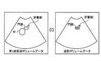
すなわち、RFA治療の効果判定では、治療計画領域に対する造影剤流入の有無を確実かつ簡便に把握することが必要となる。しかし、通常、RFA治療の効果判定は、医師が主観で行なう場合が多い。そこで、治療前のX線CTボリュームデータ、MRIボリュームデータ、又は、超音波ボリュームデータを参照画像とし、治療後の超音波ボリュームデータと参照画像との位置合せを行なって、客観的な効果判定を行なう方法が知られている。この方法は、治療前の参照画像と治療後の超音波ボリュームデータとの位置合わせに基づいて、腫瘍境界と焼灼領域境界との距離を計測し、計測した距離をカラー表示することで、医師に定量的な治療効果を提示する方法である。 That is, in determining the effect of RFA treatment, it is necessary to reliably and simply grasp the presence or absence of contrast agent inflow to the treatment plan area. However, in general, doctors often determine the effectiveness of RFA treatment subjectively. Therefore, the X-ray CT volume data, MRI volume data, or ultrasonic volume data before treatment is used as a reference image, and the ultrasonic volume data after treatment is aligned with the reference image, and objective effect determination is performed. The method of doing is known. This method measures the distance between the tumor boundary and the ablation area boundary based on the alignment between the pre-treatment reference image and the post-treatment ultrasound volume data, and displays the measured distance in color to the doctor. It is a method of presenting a quantitative therapeutic effect.
しかし、ボリュームデータの読込みやボリュームデータ間の位置合せ処理等を、穿刺治療中に即時的に行うことは困難である。例えば、上述したように、治療前後で組織像が変化したり、ガスが発生したりするため、位置合せ処理は、困難となる場合がある。また、治療現場では、医師は、追加治療の必要性を瞬時に把握する必要がある。 However, it is difficult to immediately read the volume data, align the volume data, etc. during the puncture treatment. For example, as described above, the tissue image may change before and after the treatment, and gas may be generated, which may make the alignment process difficult. Moreover, in the treatment field, the doctor needs to grasp the necessity of additional treatment instantly.
本発明が解決しようとする課題は、ラジオ波焼灼術の確実な治療効果判定を迅速かつ簡便に行なうことができる超音波診断装置及び画像処理方法を提供することである。 The problem to be solved by the present invention is to provide an ultrasonic diagnostic apparatus and an image processing method capable of quickly and easily performing reliable therapeutic effect determination of radiofrequency ablation.
実施形態の超音波診断装置は、取得部と、画像生成部と、制御部とを備える。取得部は、被検体の第1超音波画像データにて設定された関心領域の境界の位置を取得する。画像生成部は、穿刺針を用いた治療後に収集された前記被検体の造影前の画像データと造影後の画像データとにおいて、造影前後の輝度値の変化が閾値以上である画素に、当該画素と前記関心領域の境界との距離に応じた画素値を割り当てた第2超音波画像データを生成する。制御部は、前記第2超音波画像データを表示部に表示させる。 The ultrasonic diagnostic apparatus according to the embodiment includes an acquisition unit, an image generation unit, and a control unit. The acquisition unit acquires the position of the boundary of the region of interest set in the first ultrasonic image data of the subject. The image generation unit includes, in the pre-contrast image data and post-contrast image data collected after the treatment using the puncture needle, a pixel whose luminance value change before and after contrast is equal to or greater than a threshold value. And second ultrasonic image data to which pixel values corresponding to the distance between the region of interest and the boundary of the region of interest are assigned. The control unit causes the display unit to display the second ultrasonic image data.
以下、添付図面を参照して、超音波診断装置の実施形態を詳細に説明する。 Hereinafter, embodiments of an ultrasonic diagnostic apparatus will be described in detail with reference to the accompanying drawings.
(第1の実施形態)
まず、第1の実施形態に係る超音波診断装置の構成について説明する。図1は、第1の実施形態に係る超音波診断装置の構成例を示す図である。図1に示すように、第1の実施形態に係る超音波診断装置は、超音波プローブ1と、モニタ2と、入力装置3と、装置本体10とを有する。(First embodiment)
First, the configuration of the ultrasonic diagnostic apparatus according to the first embodiment will be described. FIG. 1 is a diagram illustrating a configuration example of an ultrasonic diagnostic apparatus according to the first embodiment. As shown in FIG. 1, the ultrasonic diagnostic apparatus according to the first embodiment includes an ultrasonic probe 1, a
超音波プローブ1は、装置本体10と着脱自在に接続される。超音波プローブ1は、例えば、複数の圧電振動子を有し、これら複数の圧電振動子は、後述する装置本体10が有する送受信部11から供給される駆動信号に基づき超音波を発生する。また、超音波プローブ1は、被検体Pからの反射波を受信して電気信号に変換する。また、超音波プローブ1は、圧電振動子に設けられる整合層や、圧電振動子から後方への超音波の伝播を防止するバッキング材等を有する。 The ultrasonic probe 1 is detachably connected to the apparatus
超音波プローブ1から被検体Pに超音波が送信されると、送信された超音波は、被検体Pの体内組織における音響インピーダンスの不連続面で次々と反射され、反射波信号として超音波プローブ1が有する複数の圧電振動子にて受信される。受信される反射波信号の振幅は、超音波が反射される不連続面における音響インピーダンスの差に依存する。なお、送信された超音波パルスが、移動している血流や心臓壁等の表面で反射された場合の反射波信号は、ドプラ効果により、移動体の超音波送信方向に対する速度成分に依存して、周波数偏移を受ける。 When ultrasonic waves are transmitted from the ultrasonic probe 1 to the subject P, the transmitted ultrasonic waves are reflected one after another at the discontinuous surface of the acoustic impedance in the body tissue of the subject P, and the ultrasonic probe is used as a reflected wave signal. 1 is received by a plurality of piezoelectric vibrators. The amplitude of the received reflected wave signal depends on the difference in acoustic impedance at the discontinuous surface where the ultrasonic wave is reflected. Note that the reflected wave signal when the transmitted ultrasonic pulse is reflected by the moving blood flow or the surface of the heart wall depends on the velocity component of the moving object in the ultrasonic transmission direction due to the Doppler effect. And undergoes a frequency shift.
例えば、装置本体10は、2次元走査用の超音波プローブ1として、複数の圧電振動子が一列で配置された1Dアレイプローブと接続される。或いは、例えば、装置本体10は、3次元走査用の超音波プローブ1として、メカニカル4Dプローブや2Dアレイプローブと接続される。メカニカル4Dプローブは、1Dアレイプローブのように一列で配列された複数の圧電振動子を用いて2次元走査が可能であるとともに、複数の圧電振動子を所定の角度(揺動角度)で揺動させることで3次元走査が可能である。また、2Dアレイプローブは、マトリックス状に配置された複数の圧電振動子により3次元走査が可能であるとともに、超音波を集束して送信することで2次元走査が可能である。 For example, the apparatus
ここで、第1の実施形態は、超音波プローブ1により、被検体Pが2次元走査される場合であっても、3次元走査される場合であっても適用可能である。以下では、超音波プローブ1により、被検体Pが3次元走査される場合について説明する。 Here, the first embodiment can be applied regardless of whether the subject P is two-dimensionally scanned or three-dimensionally scanned by the ultrasonic probe 1. Hereinafter, a case where the subject P is three-dimensionally scanned by the ultrasonic probe 1 will be described.
そして、第1の実施形態では、ラジオ波焼灼(RFA:Radio Frequency Ablation)治療を行なうために、図1に示すように、超音波プローブ1に穿刺アダプタ4が取り付けられる。そして、穿刺アダプタ4には、ラジオ波を発生する電極針である穿刺針5が取り付けられる。医師は、超音波プローブ1が行なった超音波送受信によりモニタ2に表示される超音波画像データを参照しながら、穿刺アダプタ4に取り付けられた穿刺針5を被検体Pの治療部位まで挿入する。ただし、第1の実施形態は、穿刺アダプタ4を用いることなく、穿刺針5による穿刺がフリーハンドで行われる場合でも適用可能である。 In the first embodiment, a puncture adapter 4 is attached to the ultrasonic probe 1 as shown in FIG. 1 in order to perform radiofrequency ablation (RFA) treatment. The puncture adapter 4 is attached with a
なお、図1には図示していないが、穿刺針5は、穿刺針5が発生するラジオ波の出力を制御する治療装置と接続される。この治療装置は、穿刺針5の温度や、ラジオ波の出力、焼灼領域のインピーダンスをモニタ可能であり、医師は、治療装置を操作して、穿刺針5を用いたRF治療を進める。 Although not shown in FIG. 1, the
そして、本実施形態に係る穿刺針5は、位置センサ51を有する。位置センサ51は、例えば、図1に示すように、穿刺針5の根元(例えば、ブラケット部位)に内蔵される。なお、位置センサ51は、穿刺針5の先端部位に内蔵される場合であっても良い。位置センサ51は、磁気センサである。また、図1に示すトランスミッター6は、任意の位置に配置され、自装置を中心として外側に向かって磁場を形成する装置である。本実施形態では、トランスミッター6は、装置本体10の近傍に設置される。なお、本実施形態は、トランスミッター6が装置本体10に取り付けられる場合であっても良い。位置センサ51は、トランスミッター6によって形成された3次元の磁場を検出する。そして、位置センサ51は、検出した磁場の情報を、装置本体10に送信する。例えば、位置センサ51は、検出した磁場の情報を、無線通信、或いは、有線通信により装置本体10に送信する。ここで、穿刺針5の根元に内蔵される位置センサ51は、穿刺針5の根元から先端に向かう方向に沿って、大きさを有する。このため、位置センサ51が検出した磁場の情報は、穿刺針5の根元の位置と、穿刺針5の3次元的な方向とを検出可能な情報となる。従って、穿刺針5の挿入経路が直線であると仮定し、穿刺針5の長さが既知であるならば、位置センサ51が検出した磁場の情報は、穿刺針5の針先の位置を検出可能な情報となる。 The
入力装置3は、マウス、キーボード、ボタン、パネルスイッチ、タッチコマンドスクリーン、フットスイッチ、トラックボール等を有し、超音波診断装置の操作者からの各種設定要求を受け付け、装置本体10に対して受け付けた各種設定要求を転送する。例えば、入力装置3は、RFA治療を行なう領域の設定を操作者から受け付ける。 The
モニタ2は、超音波診断装置の操作者が入力装置3を用いて各種設定要求を入力するためのGUI(Graphical User Interface)を表示したり、装置本体10において生成された超音波画像を表示したりする。 The
装置本体10は、超音波プローブ1が受信した反射波に基づいて超音波画像データを生成する装置であり、図1に示すように、送受信部11と、Bモード処理部12と、ドプラ処理部13と、画像生成部14と、画像メモリ15と、検出部16と、取得部17と、内部記憶部18と、制御部19とを有する。 The apparatus
送受信部11は、トリガ発生回路、遅延回路及びパルサ回路等を有し、超音波プローブ1に駆動信号を供給する。パルサ回路は、所定のレート周波数で、送信超音波を形成するためのレートパルスを繰り返し発生する。また、遅延回路は、超音波プローブ1から発生される超音波をビーム状に集束して送信指向性を決定するために必要な圧電振動子ごとの遅延時間を、パルサ回路が発生する各レートパルスに対し与える。また、トリガ発生回路は、レートパルスに基づくタイミングで、超音波プローブ1に駆動信号(駆動パルス)を印加する。すなわち、遅延回路は、各レートパルスに対し与える遅延時間を変化させることで、圧電振動子面からの送信方向を任意に調整する。 The transmission /
駆動パルスは、パルサ回路からケーブルを介して超音波プローブ1内の圧電振動子まで伝達した後に、圧電振動子において電気信号から機械的振動に変換される。この機械的振動は、生体内部で超音波として送信される。ここで、圧電振動子ごとに異なる送信遅延時間を持った超音波は、収束されて、所定方向に伝搬していく。すなわち、遅延回路は、各レートパルスに対し与える送信遅延時間を変化させることで、圧電振動子面からの送信方向を任意に調整する。 The drive pulse is transmitted from the pulser circuit to the piezoelectric vibrator in the ultrasonic probe 1 via a cable, and then converted from an electric signal to mechanical vibration in the piezoelectric vibrator. This mechanical vibration is transmitted as an ultrasonic wave inside the living body. Here, the ultrasonic waves having different transmission delay times for each piezoelectric vibrator are converged and propagated in a predetermined direction. That is, the delay circuit arbitrarily adjusts the transmission direction from the piezoelectric vibrator surface by changing the transmission delay time given to each rate pulse.
なお、送受信部11は、後述する制御部19の指示に基づいて、所定のスキャンシーケンスを実行するために、送信周波数、送信駆動電圧等を瞬時に変更可能な機能を有している。特に、送信駆動電圧の変更は、瞬間にその値を切り替え可能なリニアアンプ型の発信回路、又は、複数の電源ユニットを電気的に切り替える機構によって実現される。 The transmission /
また、送受信部11は、アンプ回路、A/D変換器、加算器等を有し、超音波プローブ1が受信した反射波信号に対して各種処理を行なって反射波データを生成する。アンプ回路は、反射波信号をチャンネルごとに増幅してゲイン補正処理を行なう。A/D変換器は、ゲイン補正された反射波信号をA/D変換し、受信指向性を決定するのに必要な受信遅延時間を与える。加算器は、与えられた遅延時間に基づき、反射波信号の加算処理を行なって反射波データを生成する。加算器の加算処理により、反射波信号の受信指向性に応じた方向からの反射成分が強調される。 The transmission /
このように、送受信部11は、超音波の送受信における送信指向性と受信指向性とを制御する。送受信部11が制御する受信指向性と送信指向性とにより、超音波送受信の総合的なビームが形成される。ここで、送受信部11は、被検体Pを2次元走査する場合、超音波プローブ1から2次元の超音波ビームを送信させる。そして、送受信部11は、超音波プローブ1が受信した2次元の反射波信号から2次元の反射波データを生成する。また、送受信部11は、被検体Pを3次元走査する場合、超音波プローブ1から3次元の超音波ビームを送信させる。そして、送受信部11は、超音波プローブ1が受信した3次元の反射波信号から3次元の反射波データを生成する。なお、送受信部11からの出力信号の形態は、RF(Radio Frequency)信号と呼ばれる位相情報が含まれる信号である場合や、包絡線検波処理後の振幅情報である場合等、種々の形態が選択可能である。 As described above, the transmission /
Bモード処理部12は、送受信部11から反射波データを受信し、受信した反射波データに対して対数増幅、包絡線検波処理等を行なって、信号強度が輝度の明るさで表現されるデータ(Bモードデータ)を生成する。 The B-
ドプラ処理部13は、送受信部11から反射波データを受信し、受信した反射波データから速度情報を周波数解析し、ドプラ効果による血流や組織、造影剤エコー成分を抽出し、平均速度、分散、パワー等の移動体情報を多点について抽出したデータ(ドプラデータ)を生成する。なお、Bモード処理部12やドプラ処理部13が生成したデータは、生データ(Raw Data)とも呼ばれる。 The
なお、Bモード処理部12は、フィルタ処理により、検波周波数を変化させることで、映像化する周波数帯域を変えることができる。このBモード処理部12の機能を用いることにより、本実施形態に係る超音波診断装置は、コントラストハーモニックイメージング(CHI:Contrast Harmonic Imaging)を実行可能である。すなわち、Bモード処理部12は、造影剤が注入された被検体Pの反射波データから、フィルタ処理により、造影剤(微小気泡、バブル)を反射源とする反射波データ(高調波データ又は分周波データ)と、被検体P内の組織を反射源とする反射波データ(基本波データ)とを分離することができる。例えば、Bモード処理部12は、造影剤が注入された被検体Pの反射波データから、2次高調波データを用いた造影画像データを生成するためのBモードデータや、基本波データを用いた組織画像データを生成するためのBモードデータを生成することができる。 The B-
また、このBモード処理部12のフィルタ処理機能を用いることにより、ティッシュハーモニックイメージング(THI:Tissue Harmonic Imaging)において、被検体Pの反射波データから、高調波データ又は分周波データを分離することで、ノイズ成分を除去した組織画像データを生成するためのBモードデータを生成することができる。なお、CHIやTHIのハーモニックイメージングを行なう際、Bモード処理部12は、上述したフィルタ処理を用いた方法とは異なる方法により、ハーモニック成分を抽出することができる。ハーモニックイメージングでは、振幅変調(AM:Amplitude Modulation)法や位相変調(PM:Phase Modulation)法、AM法及びPM法を組み合わせたAMPM法と呼ばれる映像法が行なわれる。AM法、PM法及びAMPM法では、同一の走査線に対して振幅や位相が異なる超音波送信を複数回行なう。これにより、送受信部11は、各走査線で複数の反射波データ(受信信号)を生成し出力する。そして、Bモード処理部13は、各走査線の複数の反射波データ(受信信号)を、変調法に応じた加減算処理することで、ハーモニック成分を抽出する。そして、Bモード処理部13は、ハーモニック成分の反射波データ(受信信号)に対して包絡線検波処理等を行なって、Bモードデータを生成する。 Further, by using the filter processing function of the B-
例えば、PM法が行なわれる場合、送受信部11は、制御部19が設定したスキャンシーケンスにより、例えば(−1,1)のように、位相極性を反転させた同一振幅の超音波を、各走査線で2回送信させる。そして、送受信部11は、「−1」の送信による受信信号と、「1」の送信による受信信号とを生成し、Bモード処理部12は、これら2つの受信信号を加算する。これにより、基本波成分が除去され、2次高調波成分が主に残存した信号が生成される。そして、Bモード処理部12は、この信号に対して包絡線検波処理等を行なって、THIのBモードデータやCHIのBモードデータを生成する。ここで、例えば、CHIでPM法が行なわれる場合、Bモード処理部12は、「1」の送信による受信信号をフィルタ処理することで、組織画像データを生成するためのBモードデータを生成することができる。 For example, when the PM method is performed, the transmission /
なお、図1に例示するBモード処理部12及びドプラ処理部13は、2次元の反射波データ及び3次元の反射波データの両方について処理可能である。すなわち、Bモード処理部12は、2次元の反射波データから2次元のBモードデータを生成し、3次元の反射波データから3次元のBモードデータを生成する。また、ドプラ処理部13は、2次元の反射波データから2次元のドプラデータを生成し、3次元の反射波データから3次元のドプラデータを生成する。 Note that the B-
画像生成部14は、Bモード処理部12及びドプラ処理部13が生成したデータから超音波画像データを生成する。すなわち、画像生成部14は、Bモード処理部12が生成した2次元のBモードデータから反射波の強度を輝度で表した2次元Bモード画像データを生成する。また、画像生成部14は、ドプラ処理部13が生成した2次元のドプラデータから移動体情報を表す2次元ドプラ画像データを生成する。2次元ドプラ画像データは、速度画像データ、分散画像データ、パワー画像データ、又は、これらを組み合わせた画像データである。 The
ここで、画像生成部14は、一般的には、超音波走査の走査線信号列を、テレビ等に代表されるビデオフォーマットの走査線信号列に変換(スキャンコンバート)し、表示用の超音波画像データを生成する。具体的には、画像生成部14は、超音波プローブ1による超音波の走査形態に応じて座標変換を行なうことで、表示用の超音波画像データを生成する。また、画像生成部14は、スキャンコンバート以外に種々の画像処理として、例えば、スキャンコンバート後の複数の画像フレームを用いて、輝度の平均値画像を再生成する画像処理(平滑化処理)や、画像内で微分フィルタを用いる画像処理(エッジ強調処理)等を行なう。また、画像生成部14は、超音波画像データに、付帯情報(種々のパラメータの文字情報、目盛り、ボディマーク等)を合成する。 Here, the
すなわち、Bモードデータ及びドプラデータは、スキャンコンバート処理前の超音波画像データであり、画像生成部14が生成するデータは、スキャンコンバート処理後の表示用の超音波画像データである。なお、Bモードデータ及びドプラデータは、生データ(Raw Data)とも呼ばれる。画像生成部14は、スキャンコンバート処理前の2次元超音波画像データである「2次元Bモードデータや2次元ドプラデータ」から、表示用の2次元超音波画像データである「2次元Bモード画像データや2次元ドプラ画像データ」を生成する。例えば、造影エコー法であるCHIでは、画像生成部14は、「2次元Bモード画像データ」として「2次元造影画像データ」を生成する。なお、CHIでは、画像生成部14は、必要に応じて、「2次元Bモード画像データ」として「2次元組織画像データ」を生成する。 That is, the B-mode data and Doppler data are ultrasonic image data before the scan conversion process, and the data generated by the
更に、画像生成部14は、Bモード処理部12が生成した3次元のBモードデータに対して座標変換を行なうことで、3次元Bモード画像データを生成する。また、画像生成部14は、ドプラ処理部13が生成した3次元のドプラデータに対して座標変換を行なうことで、3次元ドプラ画像データを生成する。画像生成部14は、「3次元Bモード画像データや3次元ドプラ画像データ」を「超音波ボリュームデータ」として生成する。例えば、CHIでは、画像生成部14は、「超音波ボリュームデータ」として「造影ボリュームデータ」を生成する。なお、CHIでは、画像生成部14は、必要に応じて、「超音波ボリュームデータ」として「造影ボリュームデータ」及び「組織ボリュームデータ」を生成する。 Further, the
更に、画像生成部14は、ボリュームデータをモニタ2にて表示するための各種2次元画像データを生成するために、ボリュームデータに対してレンダリング処理を行なう。画像生成部14が行なうレンダリング処理としては、例えば、断面再構成法(MPR:Multi Planer Reconstruction)を行なってボリュームデータから断面画像データ(MPR画像データ)を生成する処理がある。また、画像生成部14が行なうレンダリング処理としては、例えば、ボリュームレンダリング(VR:Volume Rendering)処理や、MIP(Maximum Intensity Projection)処理等により、VR画像データやMIP画像データ等の投影画像データを生成する処理がある。かかる投影画像データは、3次元の情報を反映した2次元画像データとなる。 Further, the
画像メモリ15は、画像生成部14が生成した表示用の画像データを記憶するメモリである。画像メモリ15が記憶する画像データは、例えば、診断の後に操作者が呼び出すことが可能である。また、画像メモリ15は、Bモード処理部12やドプラ処理部13が生成したデータを記憶することも可能である。画像メモリ15が記憶するBモードデータやドプラデータは、例えば、診断の後に操作者が呼び出すことが可能となっており、画像生成部14を経由して表示用の超音波画像データとなる。また、画像メモリ15は、送受信部11が出力したデータも記憶することが可能である。 The
検出部16は、穿刺針5が有する位置センサ51により、穿刺針5の針先の位置を検出する。すなわち、検出部16は、位置センサ51が取り付けられる穿刺針5の根元と針先との相対的位置関係の情報を用いることで、穿刺針5の針先の位置を検出する。具体的には、検出部16は、穿刺針5の根元に内蔵された位置センサ51が検出した磁場の情報を受信し、受信した情報に基づいて、穿刺針5の根元の3次元の位置を検出し、更に、穿刺針5の3次元的な方向を検出する。例えば、検出部16は、トランスミッター6を原点とする空間における穿刺針5の根元の3次元の位置を検出する。換言すると、検出部16は、実空間における根元の3次元座標を検出する。そして、検出部16は、穿刺針5の3次元的な方向と穿刺針5の長さとから、トランスミッター6を原点とする空間における穿刺針5の針先の3次元の位置を検出する。すなわち、検出部16は、実空間における針先の3次元座標を検出する。また、検出部16は、穿刺針5の針先の実空間における位置を順次検出して、3次元空間で移動する針先の軌跡を検出することで、穿刺針5の挿入経路の実空間における位置も検出可能である。上記の検出方法では、穿刺針5を用いた穿刺がフリーハンドで行われる場合でも、穿刺針5の針先及び挿入経路を検出可能である。しかし、穿刺針5を用いた穿刺が穿刺アダプタ4に取り付けられて行なわれる場合には、穿刺アダプタ4の情報から得られる穿刺針5の方向が取得可能である。そこで、検出部15は、位置センサ51が検出した情報から、根元の位置を検出し、検出した根元の位置と、穿刺アダプタ4の情報から得られる穿刺針5の方向と、既知の穿刺針5の長さとを用いて、針先の位置を検出することも可能である。また、この場合でも、検出部15は、3次元空間で移動する針先の軌跡を検出することで、穿刺針5の挿入経路の実空間における位置も検出可能である。 The
なお、検出部16が穿刺針5の針先の位置を検出可能であるならば、位置センサ51が設置される位置は、穿刺針5における任意の位置であっても良い。また、位置センサ51は、穿刺針5において、複数の位置に設置されても良い。例えば、位置センサ51は、上述したように、穿刺針5の針先に内蔵される場合であっても良い。かかる場合、検出部16は、穿刺針5の針先に内蔵された位置センサ51が検出した磁場の情報を受信し、受信した情報に基づいて、穿刺針5の針先の3次元の位置を検出する。これにより、検出部16は、実空間における針先の3次元座標を検出する。また、検出部16は、穿刺針5の針先の実空間における位置を順次検出して、3次元空間で移動する針先の軌跡を検出することで、穿刺針5の挿入経路の実空間における位置も検出可能である。また、穿刺針5の挿入経路の実空間における位置を検出する場合、位置センサは、穿刺針5と穿刺アダプタ4とにそれぞれ設置される場合であっても良い。 As long as the
取得部17は、被検体Pの第1超音波画像データにて設定された関心領域の境界の位置を取得する。本実施形態では、取得部17は、検出部16が検出した針先の位置に基づいて、穿刺針5が挿入された被検体Pの第1超音波画像データにて設定された関心領域の境界の位置を取得する。ここで、上記の第1超音波画像データは、通常Bモードで生成された組織画像データとしての超音波画像データである。例えば、本実施形態では、第1超音波画像データは、被検体Pを3次元走査して生成された第1超音波ボリュームデータであり、第1超音波ボリュームデータは、通常Bモードで生成された組織ボリュームデータである。また、上記の関心領域は、RFA治療を行なう治療計画領域であり、第1超音波ボリュームデータにおいて3次元的に設定される。本実施形態では、取得部17は、関心領域の3次元の位置を、検出部16が検出した針先の3次元の位置に基づいて取得する。なお、検出部16の検出結果に基づいて、取得部17が行なう処理については、後に詳述する。 The
内部記憶部18は、超音波送受信、画像処理及び表示処理を行なうための制御プログラムや、診断情報(例えば、患者ID、医師の所見等)や、診断プロトコルや各種ボディマーク等の各種データを記憶する。また、内部記憶部18は、必要に応じて、画像メモリ15が記憶する画像データの保管等にも使用される。なお、内部記憶部18が記憶するデータは、図示しないインターフェース回路を経由して、外部の周辺装置へ転送することができる。 The
また、例えば、内部記憶部18は、穿刺アダプタ4に対して穿刺針5が取り付けられる角度を、穿刺針5の挿入角度として記憶する。例えば、内部記憶部18は、穿刺アダプタ4が装着される場合は、穿刺アダプタ4の取り付け角度「A」を、穿刺針5の挿入角度「A」として記憶する。更に、第1の実施形態に係る内部記憶部18は、閾値及び設定情報を記憶する。内部記憶部18が記憶する閾値及び設定情報については、後に詳述する。 For example, the
制御部19は、超音波診断装置における処理全体を制御する。具体的には、制御部19は、入力装置3を介して操作者から入力された各種設定要求や、内部記憶部18から読込んだ各種制御プログラム及び各種データに基づき、送受信部11、Bモード処理部12、ドプラ処理部13、画像生成部14、検出部16及び取得部17の処理を制御する。また、制御部19は、画像メモリ15が記憶する超音波画像データ等をモニタ2にて表示するように制御する。 The
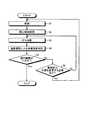
以上、第1の実施形態に係る超音波診断装置の全体構成について説明した。かかる構成のもと、第1の実施形態に係る超音波診断装置は、穿刺針5を用いたラジオ波焼灼術の確実な治療効果判定を迅速かつ簡便に行なうために、以下に説明する検出部16の検出結果に基づく取得部17の処理と、取得部17の処理結果に基づく画像生成部14の処理を行なう。まず、図2を用いて、第1の実施形態で行なわれるRFA治療のワークフローの一例について説明する。図2は、第1の実施形態で行なわれるRFA治療のワークフローの一例を示すフローチャートである。 The overall configuration of the ultrasonic diagnostic apparatus according to the first embodiment has been described above. With this configuration, the ultrasonic diagnostic apparatus according to the first embodiment has a detection unit described below in order to quickly and easily perform reliable treatment effect determination of radiofrequency ablation using the
まず、医師は、通常Bモードの超音波ガイド下で、RFA治療のための穿刺を行なう(ステップS1)。ステップS1では、画像生成部14は、通常Bモードでの3次元走査が行なわれることで、第1超音波ボリュームデータを生成する。そして、制御部19の制御により、画像生成部14は、例えば、第1超音波ボリュームデータから、通常断面(A面)の断面画像データと、穿刺針5を含む奥行き方向の断面の断面画像データを生成する。医師は、制御部19の制御によりモニタ2にリアルタイムで更新表示される2断面の画像データを参照しながら、穿刺針5を、被検体Pの治療部位まで挿入する。 First, the doctor performs puncture for RFA treatment under the normal B-mode ultrasound guide (step S1). In step S1, the
例えば、制御部19は、第1超音波ボリュームデータにおける穿刺針5を含む断面を、内部記憶部18が記憶する挿入角度「A」と、超音波プローブ1と穿刺アダプタ4との3次元的な相対的位置関係とから決定することができる。なお、穿刺針5の穿刺が、フリーハンドで行なわれている場合、穿刺針5を含む奥行き方向の断面は、A面の超音波画像データを参照した医師が、高輝度な直線を指定することで決定することができる。 For example, the
ただし、本実施形態では、取得部17が関心領域の位置を正確に取得するために、以下のような処理が行なわれることが好適である。一例として、医師は、超音波プローブ1を被検体Pの体表上で移動させて、腫瘍等の治療部位がA面の断面画像データにて描出され、かつ、A面に穿刺針5の挿入経路が含まれるように超音波プローブ1の位置を調整する。そして、医師は、調整した位置に超音波プローブ1を固定した状態で、穿刺アダプタ4に取り付けた穿刺針5の針先を被検体Pの体表に当接する。この状態で、医師は、例えば、入力装置3が有する確定ボタンを押下する。検出部16は、確定ボタンが押下された時点で位置センサ51から受信した情報から検出した穿刺針5の針先の実空間における位置を初期位置として、取得部17に通知する。 However, in the present embodiment, it is preferable that the following processing is performed in order for the
取得部17は、制御部19から3次元走査領域の形状及び大きさと、超音波プローブ1と穿刺アダプタ4との3次元的な相対的位置関係とを取得する。そして、取得部17は、制御部19から取得した情報から、検出部16が検出した初期位置が、第1超音波ボリュームデータの空間(以下、ボリューム空間と記載する)に対して「どの位置」に対応するかを取得する。これにより、取得部17は、針先の実空間における位置と、針先のボリューム空間における位置との対応付けを行なう。 The
なお、根元の位置から針先の位置を検出する際に穿刺針5の方向を穿刺アダプタ4の情報から得ている場合や、穿刺針5の針先に内蔵された位置センサ51から検出部16が針先の位置を検出している場合において、フリーハンドで穿刺が行なわれている場合、ボリューム空間における初期位置は、例えば、穿刺針5を走査領域まで被検体Pに挿入した状態で、超音波画像データを参照した医師が、高輝度な直線の先端を指定することで取得されても良い。また、上記の初期位置は、例えば、穿刺針5の針先や根元を、被検体Pの体表に当接した超音波プローブ1の振動子配列面の両端点に当接することで設定されても良い。これによっても、取得部17は、実空間における位置と、ボリューム空間における位置との対応付けを行なうことができる。 When detecting the position of the needle tip from the root position, the direction of the
かかる状態で、医師が穿刺針5を治療部位に向かって挿入すると、検出部16は、穿刺針5の実空間における針先の位置及び移動経路(挿入経路)を検出し、取得部17に通知する。取得部17は、実空間とボリューム空間との対応関係から、検出部16が検出した実空間における針先の位置及び挿入経路を、ボリューム空間における針先の位置及び挿入経路にリアルタイムで変換する。そして、取得部17が取得した情報を受信した制御部19の制御により、画像生成部14は、ステップS1において、「穿刺針5を含むA面の断面画像データ」と、「A面の断面画像データに直交し、かつ、穿刺針5の挿入経路を含む断面の断面画像データ」とを生成する。 In this state, when the doctor inserts the
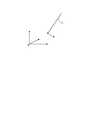
そして、医師は、治療計画領域である関心領域を設定する(ステップS2)。図3は、図1に示す検出部を説明するための図であり、図4及び図5は、図1に示す取得部を説明するための図である。検出部16は、図3に例示するように、治療部位の略中心まで挿入された穿刺針5の針先Aの実空間における3次元座標を検出する。また、検出部16は、図3に例示するように、穿刺針5の実空間における挿入経路Lの3次元座標を検出する。 Then, the doctor sets a region of interest that is a treatment plan region (step S2). FIG. 3 is a diagram for explaining the detection unit shown in FIG. 1, and FIGS. 4 and 5 are diagrams for explaining the acquisition unit shown in FIG. As illustrated in FIG. 3, the
取得部17は、検出部16から通知された情報に基づいて、穿刺針5が治療部位の略中心まで挿入された時点での第1超音波ボリュームデータにおいて、針先Aに対応する点A’の位置と、挿入経路Lに対応する線L’の位置とを取得する。そして、取得部17の制御により、画像生成部14は、図4の上図に示すように、第1超音波ボリュームデータからA面の断面画像データを生成し、更に、当該断面画像データに点A’と線L’とを重畳させた画像データを生成する。図4の上図に示す画像データは、モニタ2に表示される。医師は、図4の上図に示す画像データにおいて、関心領域を設定する。例えば、医師は、図4の下図に示すように、点A’の近傍に、治療部位である腫瘍Tを包含し5mm程度のマージンを確保した関心領域の境界M’を設定する。 Based on the information notified from the
ここで、境界M’の形状は、穿刺針5の種類から推定可能である。例えば、穿刺針5が展開型であるか、単針型であるかに応じて、境界M’の形状(3次元形状)は、楕円体や、球体となる。すなわち、関心領域の形状テンプレートは、穿刺針5の種類に応じて定められる。例えば、本実施形態では、内部記憶部18は、穿刺針5の種類に応じた様々な形状のテンプレートを記憶する。医師は、穿刺針5の種類に該当する形状のテンプレートを内部記憶部18から読み出して、画像データ上に表示させる。そして、医師は、テンプレートの中心を、点A’に置き、更に、テンプレートの境界が、腫瘍Tを包含し5mm程度のマージンが確保されるように、テンプレートの移動調整、拡大縮小調整等を行なう。かかる調整では、テンプレートの軸は、線L’に沿って設定される。なお、腫瘍Tの近傍に血管がある場合等は、医師は、近傍の血管の血流による冷却効果を考慮して、テンプレートの調整を行なう。これにより、医師は、関心領域の境界M’を設定する。 Here, the shape of the boundary M ′ can be estimated from the type of the
そして、取得部17は、ボリューム空間の針先A’に対する境界M’の相対的位置関係から、図5に例示するように、実空間における境界Mの位置を取得する。すなわち、取得部17は、図5に例示するように、実空間における針先Aの位置及び挿入経路Lの位置とともに、実空間における関心領域の境界Mの位置を取得する。なお、本実施形態は、取得部17が、医師が指定した腫瘍Tの位置に対して、自動で関心領域の境界M’を設定する場合であっても良い。或いは、本実施形態は、例えば、腫瘍Tを輝度情報に基づいて自動検出する機能を有する取得部17が、関心領域の境界M’を自動的に設定する場合であっても良い。 Then, the
図2に戻って、医師は、ステップ2で設定した関心領域に対して、RFA治療を行なう(ステップS3)。具体的には、医師は、図示しない治療装置で、穿刺針5の針先温度や、ラジオ波の出力、インピーダンス等をモニタしながら、焼灼治療を進める。 Returning to FIG. 2, the doctor performs RFA treatment on the region of interest set in step 2 (step S3). Specifically, the doctor proceeds with the ablation treatment while monitoring the needle tip temperature of the
そして、医師は、造影撮影によりRFA治療効果判定を行なう(ステップS4)。ステップS4では、穿刺針5を用いた治療後に収集された被検体Pの造影画像データを用いた第2超音波画像データが画像生成部14により生成され、モニタ2に表示される。例えば、穿刺針5を用いた治療から所定時間(例えば、約5分)が経過した後に、医師は、造影剤を投与し、関心領域内の血流が無くなっているかを、造影画像データから生成された第2超音波画像データにより、確認する。ここで、所定時間が約5分である場合、穿刺針5の針先位置及び超音波プローブ1の当接位置は、第1超音波ボリュームデータの生成時と同じ位置となる。なお、第2超音波画像データについては、後に詳述する。 Then, the doctor makes an RFA treatment effect determination by contrast imaging (step S4). In step S <b> 4, second ultrasonic image data using the contrast image data of the subject P collected after the treatment using the
そして、医師は、第2超音波画像データを参照して、焼灼範囲が十分か否かを判定する(ステップS5)。すなわち、医師は、焼灼範囲が不十分、又は、腫瘍血管の残存があるために、追加のRFA治療必要か否かを判定する。ここで、焼灼範囲が十分である場合(ステップS5肯定)、医師は、RFA治療を終了する。 Then, the doctor refers to the second ultrasonic image data and determines whether or not the cautery range is sufficient (step S5). That is, the physician determines whether additional RFA treatment is necessary due to insufficient cautery range or residual tumor blood vessels. Here, if the ablation range is sufficient (Yes at Step S5), the doctor ends the RFA treatment.
一方、焼灼範囲が十分でない場合(ステップS5否定)、医師は、第2超音波画像データを参照して、穿刺針5の位置を変更する必要があるか否かを判定する(ステップS6)。ここで、穿刺針5の位置を変更する必要が無い場合(ステップS6否定)、医師は、ステップS3に戻って、追加のRFA治療を行なう。一方、穿刺針5の位置を変更する必要がある場合(ステップS6肯定)、医師は、ステップS1に戻って、追加のRFA治療を行なうために、穿刺針5の位置を移動する穿刺を行なって、ステップS2以降の処理を行なう。 On the other hand, when the ablation range is not sufficient (No at Step S5), the doctor refers to the second ultrasonic image data and determines whether or not the position of the
以下、ステップS4で行なわれる治療効果判定において、第1の実施形態に係る超音波診断装置が行なう処理について詳細に説明する。まず、第1の実施形態に係る画像生成部14は、穿刺針5を用いた治療後に収集された被検体Pの造影前の画像データと造影後の画像データとにおいて、造影前後の輝度値の変化が閾値以上である画素に、当該画素と前記関心領域の境界との距離に応じた画素値を割り当てた第2超音波画像データを生成する。以下、上記の「造影前の画像データ及び造影後の画像データ」を「造影画像データ」と記載する。かかる処理を行なうため、第1の実施形態に係る内部記憶部16は、「輝度値変化に対する閾値」と、「境界からの距離に応じて異なる画素値とが設定された設定情報」とを記憶する。具体的には、内部記憶部18は、上記の設定情報として、「境界からの距離に応じて異なる色が設定された色情報」を記憶する。より具体的には、第1の実施形態に係る内部記憶部18は、境界の内側においては第1色調で該境界からの距離に応じて異なる色が設定され、境界の外側においては前記第1色調とは異なる第2色調で該境界からの距離に応じて異なる色が設定された色情報を、上記の設定情報として記憶する。また、第1の実施形態に係る内部記憶部18は、輝度値変化に対する閾値として、一律の値(TH)を記憶する。閾値(TH)は、造影剤の流入の有無を判定するために用いられる閾値である。 Hereinafter, the processing performed by the ultrasonic diagnostic apparatus according to the first embodiment in the therapeutic effect determination performed in step S4 will be described in detail. First, the
そして、画像生成部14は、設定情報に基づいて、第2超音波画像データを生成する。本実施形態では、画像生成部14は、色情報に基づいて、第2超音波画像データを生成する。すなわち、画像生成部14は、穿刺針5を用いた治療後に収集された被検体Pの造影画像データにおいて、造影前後の輝度値の変化が閾値(TH)以上である画素に、当該画素と関心領域の境界との距離とに対応する色を色情報に基づいて割り当てた第2超音波画像データを生成する。ここで、第1の実施形態では、「造影前の画像データ及び造影後の画像データである造影画像データ」は、被検体Pを3次元走査して生成された造影ボリュームデータである。 And the
このため、第1の実施形態に係る画像生成部14は、造影ボリュームデータにおいて、造影前後の輝度値の変化が閾値(TH)以上であるボクセルに、当該ボクセルと関心領域の境界との距離に対応するボクセル値を設定情報に基づいて割り当てた第2超音波ボリュームデータを第2超音波画像データとして生成する。設定情報が上記の色情報であることから、画像生成部14は、閾値に基づいて検出されたボクセルに、当該ボクセルと関心領域の境界との距離に対応する色を色情報に基づいて割り当てた第2超音波ボリュームデータを第2超音波画像データとして生成する。なお、上述したように、造影ボリュームデータは、第1超音波ボリュームデータの生成時と同じ位置で超音波プローブ1により3次元走査されることで生成されたボリュームデータである。すなわち、造影ボリュームデータの各ボクセルは、第1超音波ボリュームデータの各ボクセルと同一のボリューム空間上の3次元座標で表現される。 For this reason, the
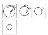
ここで、取得部17は、造影ボリュームデータを構成する各ボクセルと境界M’との距離を取得可能であることから、造影ボリュームデータを構成する各ボクセルの実空間における位置と境界Mとの距離を取得可能である。また、取得部17は、造影ボリュームデータを構成する各ボクセルと境界M’との相対的な位置関係を取得可能であることから、ボリューム空間にて関心領域の内側と外側とを判別可能である。更に、取得部17は、造影ボリュームデータを構成する各ボクセルの実空間における位置が関心領域の内側であるか外側であるのかを判定することができる。そこで、取得部17の制御に基づいて、画像生成部14は、第2超音波画像データ(第2超音波ボリュームデータ)を生成する。図6A、図6B及び図7〜図10は、第1の実施形態に係る画像生成部を説明するための図である。 Here, since the
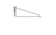
例えば、内部記憶部18が記憶する色情報は、図6Aに示すように、関心領域の境界Mからの距離「d」に応じて、異なる色が対応付けられている。図6Aに示す色情報では、関心領域の境界Mでは「d=0」であり、関心領域の内側では「d<0」であり、関心領域の外側では「d>0」である極性が設定されている。そして、図6Aに示す色情報では、「d<0」では、「dの絶対値」に応じて、第1色相の明度が変化した色調(R1、R2、R3)が割り当てられ、「d>0」では、「dの絶対値」に応じて、第2色相の明度が変化した色調(B1、B2)が割り当てられている。例えば、第1色相は、赤色系であり、第2色相は、青色系である。或いは、第2色相は、グレースケールである。関心領域内部への造影剤流入は、腫瘍の残存を意味するので、第1色相は、赤色系のように、医師に注意を促す色相であることが好適である。なお、図6A及び図6B等では、作図上、B2の色が白色となっているが、実際には、例えば、B1より薄い青色となっている。 For example, the color information stored in the
かかる色情報では、例えば、関心領域が球体である場合、図6Bに示すように、関心領域の境界Mから距離に応じて、関心領域内には球状の境界M1及び境界M2が設定され、関心領域外には球状の境界M3が設定される。 In such color information, for example, when the region of interest is a sphere, as shown in FIG. 6B, spherical boundaries M1 and M2 are set in the region of interest according to the distance from the boundary M of the region of interest. A spherical boundary M3 is set outside the region.
取得部17は、造影前のボリュームデータ(例えば、関心領域が設定された時点において、造影エコー法で取得された超音波ボリュームデータ)を構成する各ボクセルの輝度値を、造影前の輝度値「I0」として取得する。そして、取得部17は、造影エコー法で生成された造影後の画像データである造影ボリュームデータを構成する各ボクセルの輝度値「I」を取得する。すなわち、第1超音波ボリュームデータは、Bモードにより取得されたデータであることから、造影エコー法で生成された造影ボリュームデータの比較対象としては適していない。このため、関心領域が設定された後、例えば、造影剤を投与する前に、造影エコー法により超音波ボリュームデータを取得し、このボリュームデータを、造影前の画像データとし、造影剤投与後に造影エコー法で生成された造影ボリュームデータの比較対象とすることが好適である。そして、取得部17は、同一ボクセルについて、輝度値変化「I−I0」を算出し、算出した値をモニタリングする。例えば、取得部17は、全ボクセルについて、輝度値変化をモニタリングする。そして、取得部17は、「I−I0≧TH」となったボクセルの位置を実空間の位置に変換し、当該ボクセルの実空間における位置と境界Mとの距離及び位置関係を取得する。そして、取得部17は、取得した距離及び位置関係に対応する色を、図6Aに例示する色情報から取得し、取得した色を割り当てたボリュームデータを生成するように、画像生成部14を制御する。 The
例えば、画像生成部14は、図6Bに示すように、「I−I0≧TH」となったボクセルの実空間位置が境界M1内である場合、当該ボクセルに色調「R1」を割り当てる。また、例えば、画像生成部14は、図6Bに示すように、「I−I0≧TH」となったボクセルの実空間位置が境界M1と境界M2との間である場合、当該ボクセルに色調「R2」を割り当てる。また、例えば、画像生成部14は、図6Bに示すように、「I−I0≧TH」となったボクセルの実空間位置が境界M2と境界Mとの間である場合、当該ボクセルに色調「R3」を割り当てる。 For example, as illustrated in FIG. 6B, when the real space position of the voxel where “I−I0 ≧ TH” is within the boundary M1, the
また、例えば、画像生成部14は、図6Bに示すように、「I−I0≧TH」となったボクセルの実空間位置が境界Mと境界M3との間である場合、当該ボクセルに色調「B1」を割り当てる。また、例えば、画像生成部14は、図6Bに示すように、「I−I0≧TH」となったボクセルの実空間位置が境界M3の外側である場合、当該ボクセルに色調「B2」を割り当てる。 Further, for example, as illustrated in FIG. 6B, when the real space position of the voxel where “I−I0 ≧ TH” is between the boundary M and the boundary M3, the
これにより、画像生成部14は、図7に例示する第2超音波ボリュームデータを生成する。例えば、画像生成部14は、図7に例示するように、境界M’を重畳した第2超音波ボリュームデータを生成する。なお、図7に示す第2超音波ボリュームデータは、作図上、2次元の画像データとなっているが、実際には、3次元の画像データである。なお、上記の閾値は、例えば、医師等が経験的に求めた値が設定される。また、上記では、輝度値変化に対する閾値として、輝度値に対応する値が設定される場合について説明した。しかし、本実施形態は、輝度値変化に対する閾値として、例えば、「5dB」等、輝度値変化の度合いを示す値が設定される場合であっても良い。かかる場合、取得部17は、例えば、モニタ2に画像を出力するためのガンマカーブに基づいて、デ「I−I0」をシベル値に変換して、変換したデシベル値と閾値との比較処理を行なう。 Thereby, the
ここで、造影エコー法では、造影ボリュームデータが時系列に沿って生成される。画像生成部14は、取得部17の制御により、造影ボリュームデータが生成されるごとに、第2超音波ボリュームデータを生成しても良いし、造影期間中に生成された全造影ボリュームデータにおいて、輝度値変化が閾値以上となった全ボクセルを用いて第2超音波ボリュームデータを生成しても良い。 Here, in the contrast echo method, contrast volume data is generated in time series. The
すなわち、本実施形態は、第2超音波ボリュームデータが時系列に沿って生成される場合であっても良いし、造影期間中に閾値以上となった全ボクセルの位置が保持された保持型の第2超音波ボリュームデータを生成する場合であっても良い。或いは、本実施形態は、造影期間を複数の期間に分割し、各分割期間で閾値以上となった全ボクセルの位置が保持された保持型の第2超音波ボリュームデータを生成する場合であっても良い。 That is, this embodiment may be a case where the second ultrasonic volume data is generated in time series, or a holding type in which the positions of all voxels that are equal to or greater than the threshold value during the contrast period are held. The second ultrasonic volume data may be generated. Alternatively, the present embodiment is a case where the contrast period is divided into a plurality of periods, and the holding type second ultrasonic volume data in which the positions of all the voxels that are equal to or larger than the threshold value in each divided period are held is generated. Also good.
そして、制御部19は、第2超音波画像データをモニタ2に表示させる。本実施形態では、第2超音波画像データがボリュームデータ(第2超音波ボリュームデータ)として生成されることから、制御部19は、第2超音波ボリュームデータから生成された断面画像データ又は投影画像データの少なくとも1つをモニタ2に表示させる。 Then, the
例えば、画像生成部14は、制御部19の制御により、図7に例示する第2超音波ボリュームデータを、奥行き方向に沿った複数のA面で切断する。これにより、画像生成部14は、図8に示すように、複数のA面のMPR画像データを生成する。モニタ2は、図8に例示する複数のMPR画像データを表示する。腫瘍血管が空間的に不均一であったり、比較的大きい血管による冷却効果があったりすると、焼灼が計画通りに行なわれていない場合がある。このため、図8に例示する複数断面を表示することで、医師は、多断面での効果判定を行なうことができる。 For example, the
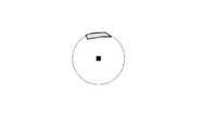
或いは、制御部19は、関心領域に限定して第2超音波画像データを表示させる。又は、制御部19は、関心領域に限定した第2超音波画像データに穿刺針5の位置を重畳表示させる。第2超音波画像データが第2超音波ボリュームデータとして生成される本実施形態では、画像生成部14は、制御部19の制御により、第2超音波ボリュームデータから関心領域内のボリュームデータを抽出し、抽出したボリュームデータを所定方向に投影した投影画像データを生成する。投影画像データは、VR画像データやMIP画像データである。例えば、画像生成部14は、抽出したボリュームデータに上述した点A’及び線L’を重畳したボリュームデータに対してMIP処理を行なうことで、図9に例示するMIP画像データを生成する。 Alternatively, the
或いは、制御部19は、第2超音波ボリュームデータにおいて穿刺針5の針先を含み、かつ、穿刺針5の挿入経路に直交する断面で第2超音波ボリュームデータを切断した断面画像データを表示させる。ここで、制御部19は、この断面画像データを関心領域に限定した断面画像データとしても良い。例えば、画像生成部14は、制御部19の制御により、第2超音波ボリュームデータから関心領域内のボリュームデータを抽出する。また、取得部17は、抽出されたボリュームデータにおいて、上述した点A’を含み、かつ、線L’に直交する断面の位置を取得する。画像生成部14は、抽出したボリュームデータを、取得部17が取得した断面で切断することで、図10に例示するMPR画像データを生成する。なお、図9及び図10に例示する画像データには、境界M’に対応する円が点線で重畳されている。かかる点線は、画像生成部14により描画される。 Alternatively, the
なお、モニタ2に表示される表示用画像データは、上述したように、第2超音波ボリュームデータから生成された2次元画像データに限定されるものではない。例えば、制御部19は、被検体Pの組織が描出された超音波画像データ及び被検体Pの造影剤分布が描出された超音波画像データの少なくとも1つと、第2超音波ボリュームデータから生成された2次元画像データとを重畳した画像データをモニタ2に表示させても良い。被検体Pの組織が描出された超音波画像データは、例えば、第1超音波ボリュームデータや造影ボリュームデータの生成元である3次元反射波データから生成された基本波のボリュームデータである。また、被検体Pの造影組織が描出された超音波画像データは、第2超音波ボリュームデータの生成に用いた造影ボリュームデータである。 Note that the display image data displayed on the
例えば、画像生成部14は、取得部17の位置合わせ指示により、第2超音波ボリュームデータと重畳対象となるボリュームデータとを合成したボリュームデータを用いて、MPR処理、VR処理、MIP処理等を行なうことで、重畳画像データを生成する。なお、画像生成部14は、例えば、重畳対象となるボリュームデータの不透明度を下げたうえで、ボリュームデータを合成する。 For example, the
上述した各種の表示用画像データは、第2超音波ボリュームデータが時系列に沿って複数生成される場合、各第2超音波ボリュームデータから生成される。また、上述した各種の表示用画像データは、保持型の第2超音波ボリュームデータが1つ生成される場合、1つの第2超音波ボリュームデータから生成される。また、上述した各種の表示用画像データは、保持型の第2超音波ボリュームデータが複数生成される場合、複数の第2超音波ボリュームデータそれぞれから生成される。 The various types of display image data described above are generated from each second ultrasonic volume data when a plurality of second ultrasonic volume data are generated in time series. Further, the various types of display image data described above are generated from one second ultrasonic volume data when one piece of holding-type second ultrasonic volume data is generated. Further, the various types of display image data described above are generated from each of the plurality of second ultrasonic volume data when a plurality of holding-type second ultrasonic volume data are generated.
このように、第2超音波画像データは、焼灼治療後に残存している血流と、関心領域の境界との位置関係を、治療効果判定を行なう医師が把握するために提供される画像データである。上記では、かかる画像データを生成するための設定情報として、境界からの距離に応じて異なる色が設定された色情報を用いる場合について説明した。しかし、焼灼治療後に残存している血流と、関心領域の境界との位置関係を提示するための設定情報は、上記の色情報に限定されるものではない。例えば、境界からの距離に応じて異なる画素値が設定された設定情報は、境界からの距離に応じて異なるハッチングが設定されたハッチング情報であっても良い。或いは、設定情報は、境界からの距離に応じて同系色で異なる濃淡が設定された濃淡情報であっても良い。例えば、濃淡情報は、境界からの距離に応じてグレースケールで異なるグラデーションが設定された濃淡情報であっても良い。 As described above, the second ultrasonic image data is image data provided for the doctor who performs the therapeutic effect determination to grasp the positional relationship between the blood flow remaining after the cauterization treatment and the boundary of the region of interest. is there. The case has been described above where color information in which different colors are set according to the distance from the boundary is used as setting information for generating such image data. However, the setting information for presenting the positional relationship between the blood flow remaining after the cauterization treatment and the boundary of the region of interest is not limited to the color information described above. For example, the setting information in which different pixel values are set according to the distance from the boundary may be hatching information in which different hatching is set according to the distance from the boundary. Alternatively, the setting information may be shading information in which different shadings are set in similar colors according to the distance from the boundary. For example, the shading information may be shading information in which different gradations are set in gray scale according to the distance from the boundary.
次に、図11を用いて、第1の実施形態に係る超音波診断装置が行なう処理の一例について説明する。図11は、第1の実施形態に係る超音波診断装置が行なう処理の一例を示すフローチャートである。なお、図11は、図2に例示したステップS4において、超音波診断装置が行なう処理の一例を示すフローチャートである。 Next, an example of processing performed by the ultrasonic diagnostic apparatus according to the first embodiment will be described with reference to FIG. FIG. 11 is a flowchart illustrating an example of processing performed by the ultrasonic diagnostic apparatus according to the first embodiment. FIG. 11 is a flowchart illustrating an example of processing performed by the ultrasonic diagnostic apparatus in step S4 illustrated in FIG.
図11に例示するように、第1の実施形態に係る超音波診断装置の取得部17は、造影ボリュームデータが収集されたか否かを判定する(ステップS101)。ここで、造影ボリュームデータが収集されていない場合(ステップS101否定)、取得部17は、造影ボリュームデータが収集されるまで待機する。 As illustrated in FIG. 11, the
一方、造影ボリュームデータが収集された場合(ステップS101肯定)、取得部17は、造影ボリュームデータにおける関心領域の位置を取得する。そして、画像生成部14は、取得部17の制御により、輝度値が閾値以上上昇したボクセルに、当該ボクセルと関心領域との距離に対応する色を割り当てた第2超音波ボリュームデータを生成する(ステップS102)。 On the other hand, when contrast volume data is collected (Yes at Step S101), the
そして、画像生成部14は、制御部19の制御により、少なくとも第2超音波ボリュームデータを用いた表示用画像データを生成する(ステップS103)。そして、モニタ2は、制御部19の制御により、表示用画像データを表示し(ステップS104)、処理を終了する。 Then, the
上述したように、第1の実施形態では、針先の位置を位置センサ51で正確かつ簡便に検出することで、針先の位置及び穿刺針5の種類に基づいて設定された関心領域の境界位置を実空間及びボリューム空間で正確かつ簡便に取得することができる。そして、第1の実施形態では、カラーマップ(色情報)の基準を関心領域の境界(治療計画領域の境界)とし、正確に取得した関心領域の境界位置に基づいて、治療計画領域内や治療計画領域近傍への造影剤流入を異なる色相で強調された表示用画像データを、迅速に生成表示することができる。そして、医師は、造影剤流入を異なる色相で強調された表示用画像データを参照することで、血流の残存部位を容易に視認することができる。従って、第1の実施形態では、ラジオ波焼灼術の確実な治療効果判定を迅速かつ簡便に行なうことができる。 As described above, in the first embodiment, the boundary of the region of interest set based on the position of the needle tip and the type of the
なお、第1の実施形態では、以下に説明する変形例を行なっても良い。図12A、図12B、図13A及び図13Bは、第1の実施形態に係る変形例を説明するための図である。 Note that the first embodiment may be modified as described below. 12A, 12B, 13A, and 13B are diagrams for explaining a modification according to the first embodiment.
第1変形例では、制御部19は、更に、関心領域内の輝度値の時間にともなう変化を示す時間変化曲線を表示させる。すなわち、造影ボリュームデータは、時系列に沿って複数生成されることから、例えば、制御部19は、関心領域内の時間変化曲線を生成することができる。そこで、制御部19は、図12Aに例示するように、関心領域内の輝度(Intensity)を時間(time)に沿ってプロットした時間変化曲線を生成して、画像データとともに表示させる。なお、制御部19は、関心領域内の平均輝度値をプロットした1つの時間変化曲線を生成しても、関心領域内の複数のボクセルそれぞれの輝度値をプロットした複数の時間変化曲線を生成しても良い。或いは、制御部19は、関心領域内の複数の領域(境界M1内、境界M1と境界M2とで挟まれる領域、境界M2と境界Mとで挟まれる領域等)それぞれの平均輝度値をプロットした複数の時間変化曲線を生成しても良い。また、制御部19は、関心領域外の時間変化曲線を生成しても良い。 In the first modified example, the
或いは、第1変形例では、制御部19は、更に、関心領域内で画素値が割り当てられた領域の該関心領域に対する割合を表示させる。設定情報として色情報が用いられる場合、制御部19は、関心領域内で色が割り当てられた領域の該関心領域に対する割合を表示させる。例えば、制御部19は、関心領域内で輝度値変化が閾値以上となったボクセル数を、関心領域のボクセル数で除算することで、割合を算出し、モニタ2に表示させても良い。例えば、制御部19は、図12Bに示すように、関心領域の体積に対する関心領域内の造影剤流入体積の割合「5%」を算出して、モニタ2に表示させる。なお、上記の割合は、関心領域全体に対して算出される場合であっても、関心領域内の複数の領域それぞれに対して算出される場合であっても良い。また、制御部19は、関心領域外の領域において、割合を算出しても良い。また、上記の割合は、第2超音波ボリュームデータが複数生成される場合、各第2超音波ボリュームデータから算出される。 Alternatively, in the first modification, the
このような時間変化曲線や割合を参照することで、医師は、更に、RFA治療の効果判定を、客観的かつ効率的に行なうことができる。 By referring to such a time change curve and ratio, the doctor can further objectively and efficiently determine the effect of the RFA treatment.
第2変形例では、画像生成部14は、関心領域の内部、又は、関心領域の内部及び関心領域の境界近傍の外側に限局した領域にて第2超音波画像データを生成する。例えば、図13Aに例示するように、取得部17は、境界Mの内部に限定して、第2超音波ボリュームデータを生成するように、画像生成部14を制御する。或いは、図13Bに例示するように、画像生成部14は、境界Mの外側の境界である境界M3の内部に限定して、第2超音波ボリュームデータを生成する。すなわち、第2変形例では、造影剤による輝度上昇の監視領域を限局することで、第2超音波ボリュームデータの生成処理における負荷を軽減することができる。 In the second modification, the
なお、第1の実施形態で説明した処理は、位置センサ51及び検出部16を用いずに行われる場合であっても良い。上述したように、治療効果判定用の画像データである第2超音波ボリュームデータは、実空間における距離を元に設定された設定情報に基づいて、生成される。すなわち、ボリューム空間における距離を実空間における距離に変換することが可能であれば、画像生成部14は、第2超音波ボリュームデータを生成することができる。ここで、送受信部11、Bモード生成部12及び画像生成部14を制御する制御部19は、超音波の走査領域の形状及び大きさと、超音波画像データの形状及び大きさとの対応関係を取得可能である。また、かかる対応関係から、制御部19は、ボリューム空間における距離を実空間における距離に変換するための変換情報を取得可能である。 Note that the processing described in the first embodiment may be performed without using the
そこで、例えば、取得部17は、上記の変換情報を、制御部19から取得する。そして、例えば、取得部17は、取得した変換情報を用いて、輝度値の変化が閾値以上である画素と境界との距離を、実空間における距離に変換する。そして、取得部17は、変換後の距離から当該画素に割り当てる色を取得する。このような処理によっても、画像生成部14は、上記の第2超音波ボリュームデータを生成表示することが可能となる。 Therefore, for example, the
(第2の実施形態)
第1の実施形態では、関心領域(治療計画領域)内外への造影剤流入に関する情報を、境界からの距離に応じた色を割り当てた色情報を用いて強調表示する際に、輝度値上昇に対する閾値を、一律の値とする場合について説明した。第2の実施形態では、造影剤による輝度上昇に対する閾値が一律ではない場合について、図14を用いて説明する。図14は、第2の実施形態を説明するための図である。(Second Embodiment)
In the first embodiment, when information on contrast agent inflow into and out of a region of interest (treatment planning region) is highlighted using color information assigned a color according to the distance from the boundary, The case where the threshold value is a uniform value has been described. In the second embodiment, a case where the threshold for the increase in luminance due to the contrast agent is not uniform will be described with reference to FIG. FIG. 14 is a diagram for explaining the second embodiment.
第2の実施形態に係る内部記憶部18は、輝度値変化に対する閾値として、境界からの距離に応じて異なる値の複数の閾値を記憶する。例えば、内部記憶部18は、図14に例示するように、図6の(A)に例示する色調「R1、R2、R3」を割り当てる距離「d<0」の関心領域内では、一律の閾値「TH1」が設定された情報を記憶する。また、例えば、内部記憶部18は、図14に例示するように、図6の(A)に例示する色調「B1」を割り当てる距離「d>0」の関心領域外では、TH1より大きい一律の閾値「TH2」が設定された情報を記憶する。 The
そして、例えば、内部記憶部18は、図14に例示するように、図6の(A)に例示する色調「B2」を割り当てる距離「d>0」の関心領域外では、dに比例して閾値がTH2からTH3へと一次関数で増大する閾値が設定された情報を記憶する。なお、距離に応じた閾値は、操作者により任意に設定可能である。 Then, for example, as illustrated in FIG. 14, the
そして、第2の実施形態に係る画像生成部14は、関心領域の境界からの距離に対応する閾値以上となった画素に、当該画素と関心領域の境界との距離とに対応する色を色情報に基づいて割り当てて第2超音波画像データを生成する。第2の実施形態では、第1の実施形態と同様に、3次元走査が行なわれる。従って、第2の実施形態に係る画像生成部14は、関心領域の境界からの距離に対応する閾値以上となったボクセルに、当該ボクセルと関心領域の境界との距離とに対応する色を色情報に基づいて割り当てて第2超音波ボリュームデータを生成する。なお、第2の実施形態においても、色情報以外の設定情報(ハッチング情報や、濃淡情報)を用いて、境界からの距離に応じた画素値を割り当てることで、第2超音波ボリュームデータを生成しても良い。 Then, the
そして、第2の実施形態においても、第1の実施形態で説明した表示用画像データや、時間変化曲線、割合が表示される。なお、閾値が境界との距離に応じて変化する以外、第1の実施形態で説明した内容は、第2の実施形態においても適用される。また、第2の実施形態に係る超音波診断装置の処理は、図11で説明したステップS102の処理が、例えば、図14に示す設定情報を用いた閾値判定が行なわれる以外、第1の実施形態と同様であるので、説明を省略する。 Also in the second embodiment, the display image data, the time change curve, and the ratio described in the first embodiment are displayed. The contents described in the first embodiment are also applied to the second embodiment, except that the threshold value changes according to the distance from the boundary. The processing of the ultrasonic diagnostic apparatus according to the second embodiment is the same as that of step S102 described in FIG. 11 except that the threshold determination using the setting information shown in FIG. 14 is performed, for example. Since it is the same as that of the form, the description is omitted.
RFA治療の効果判定では、関心領域内の造影剤流入の有無が重要であるが、関心領域外側であっても、近傍に比較的大きな血管があれば冷却効果をもたらし、治療に影響する場合がある。図14に例示する設定情報は、関心領域の外側近傍に位置する比較的大きな血管の視認性を向上させるためのカラーマップの一例となる。 In determining the effect of RFA treatment, the presence or absence of contrast medium inflow in the region of interest is important, but even if outside the region of interest, if there is a relatively large blood vessel in the vicinity, a cooling effect may be brought about, which may affect the treatment. is there. The setting information illustrated in FIG. 14 is an example of a color map for improving the visibility of a relatively large blood vessel located near the outside of the region of interest.
第2の実施形態では、かかるカラーマップを用いて、関心領域外側であっても輝度上昇が大きい血管を強調表示することで、医師による関心領域設定の妥当性確認や、追加治療計画の補助となりうる情報を提供することができる。なお、第2の実施形態は、関心領域内においても、距離に応じて、複数の閾値が設定される場合であっても良い。 In the second embodiment, the color map is used to highlight a blood vessel with a large increase in luminance even outside the region of interest, thereby helping to validate the region of interest setting by the doctor and assist additional treatment planning. Possible information can be provided. Note that the second embodiment may be a case where a plurality of threshold values are set according to the distance even in the region of interest.
(第3の実施形態)
第3の実施形態では、穿刺針5が抜かれた後に造影画像データ(造影ボリュームデータ)が収集される場合の処理について、図15A及び図15Bを用いて説明する。図15A及び図15Bは、第2の実施形態を説明するための図である。(Third embodiment)
In the third embodiment, processing when contrast image data (contrast volume data) is collected after the
すなわち、第1及び第2の実施形態では、図2に示すステップS4において、穿刺針5の位置が固定された状態で、造影ボリュームデータが収集される場合について説明した。かかる場合、第1ボリュームデータと造影ボリュームデータとの位置関係は、一意に特定可能である。しかし、RFA治療の効果判定は、5分後等の短期間の後に行なわれる場合だけでなく、例えば、5日後等、数日の後に行なわれる場合がある。かかる場合、穿刺針5が挿入されていない状態で収集された造影ボリュームデータを用いて、医師は、治療効果の判定を行なって、ステップS5やステップS6の判定を行なう必要がある。 That is, in the first and second embodiments, the case where the contrast volume data is collected in the state where the position of the
そこで、第3の実施形態に係る取得部17は、穿刺針5が抜かれた後に造影画像データ(造影ボリュームデータ)が収集される場合、第1超音波画像データ(第1超音波ボリュームデータ)と造影画像データ(造影ボリュームデータ)との位置合わせを行なう。そして、第3の実施形態に係る取得部17は、位置合わせの結果から、造影画像データ(造影ボリュームデータ)における関心領域に対応する対応領域の位置を取得する。具体的には、取得部17は、第1超音波画像データ(第1超音波ボリュームデータ)にて関心領域の周囲に描出された構造物に基づく位置合わせを行なう。 Therefore, when the contrast image data (contrast volume data) is collected after the
例えば、取得部17は、図15Aに示すように、第1超音波ボリュームデータにおいて、関心領域の境界Mに対応する境界M’の近傍に位置する門脈や肝動脈の位置を取得する。第1超音波ボリュームデータの門脈や肝動脈の位置は、例えば、医師や技師等により指定される場合であってもよいし、輝度値の情報から、取得部17が取得する場合であっても良い。そして、取得部17は、造影ボリュームデータにおける門脈や肝動脈の位置を取得する。造影ボリュームデータの門脈や肝動脈の位置は、例えば、医師や技師等により指定される場合であってもよいし、輝度値の情報から、取得部17が取得する場合であっても良い。 For example, as illustrated in FIG. 15A, the
これにより、取得部17は、第1超音波ボリュームデータと造影ボリュームデータとの位置合わせを行なう。或いは、取得部17は、位置センサの下、血管等の構造体の位置情報を用いて第1超音波ボリュームデータと造影ボリュームデータとの初期的な位置合わせを行ない、更に、一方のボリュームデータを微小距離移動させながら他方のボリュームデータとの位置合わせを完了する。 Thereby, the
すなわち、穿刺針5が抜かれた後に造影ボリュームデータを収集する際には、位置合わせを正確に行なうため、例えば、医師は、位置センサ51を有する穿刺針5を、超音波プローブ1が当接される体表に穿刺針5の針先を当接する。なお、造影ボリュームデータの収集時に超音波プローブ1が当接される体表の位置は、通常、第1超音波ボリュームデータが収集された位置となるように調整される。これにより、検出部15は、針先の位置を検出する。この時に針先が当接される位置は、治療用の穿刺が行なわれた際に、穿刺針5が挿入された体表の位置と略同一位置であることが好適である。これにより、取得部17は、造影ボリュームデータ収集時の針先の位置を取得することができる。一方、取得部17は、上述したように、RFA治療時にて、穿刺針5が挿入された体表の位置を取得しておくことが可能である。取得部17は、検出部15が検出した治療前後での位置情報を用いて、初期的に行なった位置合わせを修正する。これにより、取得部17は、第1超音波ボリュームデータと造影ボリュームデータとの正確な位置合わせを行なうことができる。 That is, when collecting the contrast volume data after the
或いは、例えば、医師は、位置センサが取り付けられた超音波プローブ1を用いて、穿刺針5が抜かれた後の造影ボリュームデータを収集する場合であっても良い。検出部15は、超音波プローブ1に取り付けられた位置センサを用いて、超音波プローブ1の当接位置を検出可能である。取得部17は、第1超音波ボリュームデータ収集時の穿刺針5の挿入位置と、造影ボリュームデータ収集時における超音波プローブ1の当接位置とから、第1超音波ボリュームデータと造影ボリュームデータとの位置合わせを正確に行なうことが可能である。なお、造影ボリュームデータ収集時における超音波プローブ1の当接位置を用いる場合、第1超音波ボリュームデータ収集時にも、超音波プローブ1に位置センサを取り付けておいても良い。これによっても、取得部17は、第1超音波ボリュームデータと造影ボリュームデータとの位置合わせを正確に行なうことが可能である。位置センサを用いて位置合わせを行なう場合、関心領域の周囲に描出された構造物に基づく初期位置合わせは、行なわない場合であっても良い。 Alternatively, for example, the doctor may collect contrast volume data after the
なお、位置合わせ処理は、血管等の構造体を用いる場合だけでなく、治療前後の略同一時相の造影ボリュームデータ、又は、治療前後の組織ボリュームデータに対して、相互情報量や、画像相関等の公知の技術を用いて行なわれる場合であっても良い。かかる場合には、例えば、医師は、第1超音波ボリュームデータ収集後に、第1超音波ボリュームデータと同一の3次元走査領域で、RFA治療前の造影ボリュームデータを収集しておく。RFA治療前の造影ボリュームデータは、例えば、血管構造が染影される動脈相の造影ボリュームデータである。そして、取得部17は、RFA治療後に穿刺針5が抜かれた状態で収集された造影ボリュームデータ群から、RFA治療前の造影ボリュームデータと同一時相の造影ボリュームデータを取得する。そして、取得部17は、これら2つの造影ボリュームデータの位置合わせを、相互情報量や、画像相関等を用いた手法により行なう。これにより、取得部17は、第1超音波ボリュームデータと造影ボリュームデータとの位置合わせを正確に行なうことが可能である。 Note that the alignment processing is not limited to the case of using a structure such as a blood vessel, but the mutual information amount and image correlation for contrast volume data at substantially the same time phase before and after treatment or tissue volume data before and after treatment. It is also possible to use a known technique such as. In such a case, for example, the doctor collects contrast volume data before RFA treatment in the same three-dimensional scanning region as the first ultrasound volume data after collecting the first ultrasound volume data. The contrast volume data before the RFA treatment is, for example, contrast volume data of the arterial phase in which the blood vessel structure is stained. And the
或いは、例えば、医師は、RFA治療後の造影ボリュームデータを収集する前に、Bモードにより組織ボリュームデータを収集する。そして、取得部17は、第1超音波ボリュームデータと組織ボリュームデータとの位置合わせを、相互情報量や、画像相関等を用いた手法により行なう。これにより、取得部17は、第1超音波ボリュームデータと造影ボリュームデータとの位置合わせを正確に行なうことが可能である。なお、相互情報量や、画像相関等を用いた手法を行なう場合にも、上記の位置センサを用いた位置合わせを更に行なっても良い。 Alternatively, for example, a doctor collects tissue volume data in B mode before collecting contrast volume data after RFA treatment. Then, the
そして、取得部17は、位置合わせの結果から、図15Bの左図に示すように、造影ボリュームデータのボリューム空間における対応領域の境界MA’の位置を取得する。ここで、取得部17は、関心領域の設定時等において、第1超音波ボリュームデータのボリューム空間と実空間との対応付けを行なっている。また、取得部17は、位置合わせにより、造影ボリュームデータのボリューム空間と第1超音波ボリュームデータのボリューム空間との対応付けを完了している。従って、取得部17は、図15Bの右図に示すように、造影ボリュームデータのボリューム空間における対応領域の境界MA’の位置から、実空間における対応領域の境界MAの位置を取得することができる。 Then, the
そして、第3の実施形態に係る画像生成部14は、対応領域の境界の位置に基づいて、第2超音波画像データ(第2超音波ボリュームデータ)を生成する。 Then, the
そして、第3の実施形態においても、第1の実施形態で説明した表示用画像データや、時間変化曲線、割合が表示される。なお、造影ボリュームデータにおける関心領域に対応する領域の境界位置が、位置合わせ処理により取得される以外、第1及び第2の実施形態で説明した内容は、第3の実施形態においても適用される。また、第3の実施形態に係る超音波診断装置の処理は、図11で説明したステップS102の処理が、対応領域の境界を用いて行なわれる以外、第1の実施形態と同様であるので、説明を省略する。 Also in the third embodiment, the display image data, the time change curve, and the ratio described in the first embodiment are displayed. The contents described in the first and second embodiments are also applied to the third embodiment, except that the boundary position of the region corresponding to the region of interest in the contrast volume data is acquired by the alignment process. . The processing of the ultrasonic diagnostic apparatus according to the third embodiment is the same as that of the first embodiment except that the processing of step S102 described in FIG. 11 is performed using the boundary of the corresponding region. Description is omitted.
第3の実施形態では、穿刺針5が抜かれた状態で治療効果の判定が行なわれる場合であっても、関心領域の位置を正確に取得しておくことで、位置合わせ処理の結果から造影ボリュームデータにおける対応領域の位置を正確に取得することができる。また、第3の実施形態で行なわれる位置合わせ処理は、超音波ボリュームデータ間の位置合わせであるため、他種のボリュームデータ間の位置合わせと比較して、正確かつ迅速に行なうことができる。従って、第3の実施形態では、ラジオ波焼灼術の確実な治療効果判定を、任意の時期において、迅速かつ簡便に行なうことができる。 In the third embodiment, even if the determination of the therapeutic effect is performed with the
(第4の実施形態)
第4の実施形態では、穿刺針5を用いた治療が、穿刺針5の位置を変更して複数回行なわれる場合に適用される変形例について、図16等を用いて説明する。図16は、第4の実施形態を説明するための図である。(Fourth embodiment)
In the fourth embodiment, a modification applied when treatment using the
RFA治療では、通常、穿刺針5の位置を変更して、焼灼が複数回行なわれる。上述した第1及び第2の実施形態では、ステップS6で穿刺針5の位置を変更する必要があると判定された場合、ステップS1〜ステップS4の処理が再度実行される。かかる場合、穿刺針5の位置が変更された後、ステップS2で新たな関心領域が設定される。そして、新たな関心領域の境界を用いて、治療効果判定用の画像データの生成表示が行なわれる。 In the RFA treatment, usually, the position of the
しかし、医師にとっては、現時点で設定した関心領域に、過去に設定した1つ又は複数の関心領域を併せて治療効果判定を行なうことが望ましい。 However, it is desirable for the doctor to determine the therapeutic effect by combining one or more regions of interest set in the past with the region of interest set at the present time.
そこで、第4の実施形態に係る取得部17は、穿刺針5を用いた治療が、穿刺針5の位置を変更して複数回行なわれる場合、各治療において設定された複数の関心領域を合成した合成領域の境界の位置を取得する。そして、第5の実施形態に係る画像生成部14は、合成領域の境界の位置に基づいて、第2超音波画像データを生成する。 Therefore, when the treatment using the
図16の左図に示す「L(1st)」は、1回目の焼灼治療で穿刺針5が挿入された実空間における挿入経路を示す。また、図16の左図に示す「M(1st)」は、「挿入経路L(1st)の先端(穿刺針5の針先)」の位置に基づいて設定された関心領域の実空間における境界の位置を示す。また、図16の中図に示す「L(2nd)」は、1回目の焼灼治療が不十分であったため、焼灼する位置を変更するために2回目の焼灼治療で穿刺針5が挿入された実空間における挿入経路を示す。また、図16の中図に示す「M(2nd)」は、「挿入経路L(2nd)の先端(穿刺針5の針先)」の位置に基づいて設定された関心領域の実空間における境界の位置を示す。 “L (1st)” shown in the left diagram of FIG. 16 indicates an insertion path in the real space where the
かかる場合、取得部17は、図16の右図に示すように、境界M(1st)と境界M(2nd)とを合成した合成境界CMの位置を取得する。また、取得部17は、実空間の合成境界CMに対応するボリューム空間の合成境界の位置も取得する。 In this case, the
そして、取得部17は、1つの閾値(又は、複数の閾値)と、設定情報とを用いて、第2超音波画像データ(第2超音波ボリュームデータ)を生成するように、画像生成部14を制御する。そして、画像生成部14は、第1の実施形態で説明した様々な表示用画像データを、第2超音波ボリュームデータを用いて生成し、モニタ2に出力する。例えば、モニタ2は、合成境界に基づく第2超音波ボリュームデータから生成されたMPR画像データに、境界M(1st)及び境界M(2nd)の位置を示す線が重畳された画像データを表示する。 Then, the
上述したように、第4の実施形態では、合成境界を用いた第2超音波画像データを生成表示することで、複数回行なったラジオ波焼灼術の治療効果判定を、総合的に迅速かつ簡便に行なうことができる。なお、本実施形態の変形例として、制御部19は、例えば、第2超音波画像データの生成表示については、最新の関心領域の境界位置に基づいて実行させ、当該第2超音波画像データを生成表示させる際に、前回や前々回の関心領域の境界を点線により表示させても良い。 As described above, in the fourth embodiment, the second ultrasonic image data using the composite boundary is generated and displayed, so that the determination of the therapeutic effect of the radiofrequency ablation performed multiple times can be performed quickly and easily. Can be done. As a modification of the present embodiment, for example, the
(第5の実施形態)
第5の実施形態では、上述した第1〜第4の実施形態に適用可能な設定情報の変形例について、図17及び図18等を用いて説明する。図17及び図18は、第5の実施形態を説明するための図である。(Fifth embodiment)
In the fifth embodiment, a modification of setting information applicable to the first to fourth embodiments described above will be described with reference to FIGS. 17 and 18. 17 and 18 are diagrams for explaining the fifth embodiment.
上述した第1〜第4の実施形態では、造影前後の輝度値の変化が前記閾値以上である画素に、当該画素と関心領域の境界との距離に応じた画素値(例えば、色)を割り当てることで、第2超音波画像データ(第2超音波ボリュームデータ)を生成する。かかる第2超音波画像データを参照することで、医師は、関心領域内や関心領域外で残存している血流の有無を判定することができる。ここで、治療効果を判定する医師にとって、焼灼治療後に残存している血流が、血管内(例えば、腫瘍の栄養血管内)を流動している血流であるのか、毛細血管からを介して組織内を流動している灌流(perfusion)であるのを判断することも重要である。 In the first to fourth embodiments described above, a pixel value (for example, color) corresponding to the distance between the pixel and the region of interest is assigned to a pixel whose luminance value change before and after contrast is equal to or greater than the threshold value. Thus, second ultrasonic image data (second ultrasonic volume data) is generated. By referring to the second ultrasonic image data, the doctor can determine the presence or absence of blood flow remaining in or outside the region of interest. Here, for the doctor who judges the therapeutic effect, whether the blood flow remaining after the cauterization treatment is the blood flow flowing in the blood vessel (for example, in the nutrient blood vessel of the tumor) or via the capillary blood vessel It is also important to determine perfusion flowing through the tissue.
造影撮影では、血管内に造影剤が流動した後に、毛細血管内に造影剤が流動する。すなわち、造影撮影では、血管内で輝度値が上昇した後に、毛細血管内で輝度値が上昇する。そこで、第5の実施形態に係る画像生成部14は、造影前後の輝度値の変化が閾値以上である画素に、当該画素と関心領域の境界との距離、及び、当該画素で輝度値の変化が閾値以上となった時間に応じた画素値を割り当てて、第2超音波画像データを生成する。例えば、内部記憶部16は、境界からの距離、及び、時間に応じて異なる画素値が設定された設定情報を記憶する。一例として、内部記憶部16は、境界からの距離、及び、時間に応じて異なる色が設定された色情報を記憶する。換言すると、上記の色情報は、図6Aや図14に示す色情報に、時間軸を追加した色情報となる。 In contrast imaging, after the contrast agent flows into the blood vessel, the contrast agent flows into the capillary. That is, in contrast imaging, the luminance value increases in the capillary after the luminance value increases in the blood vessel. Therefore, the
例えば、内部記憶部16は、図17に示すように、色調「R1」の不透明度が、時間(t)とともに低下する色情報を記憶する。取得部16は、図17に例示する色情報を用いて、第2超音波画像データ(第2超音波ボリュームデータ)を画像生成部14に生成させる。かかる処理により生成された第2超音波画像データでは、早く閾値を越えた位置の画素ほど、不透明度が高い色で描出され、遅く閾値を越えた位置の画素ほど、透明度が高い色で描出されることになる。医師は、同じ色調であっても、透明度を把握することで、血流と灌流とを判別することができる。 For example, as illustrated in FIG. 17, the
また、造影撮影では、血管内で輝度値の上昇度合いが高く、毛細血管内で輝度値の上昇度合いが低い。そこで、第5の実施形態に係る画像生成部14は、造影前後の輝度値の変化が閾値以上である画素に、当該画素と関心領域の境界との距離、及び、当該画素における輝度値の変化量に応じた画素値を割り当てて、第2超音波画像データを生成する。例えば、内部記憶部16は、境界からの距離、及び、時間に応じて異なる画素値が設定された設定情報を記憶する。一例として、内部記憶部16は、境界からの距離、及び、輝度値の変化量(dI=I−I0)に応じて異なる色が設定された色情報を記憶する。換言すると、上記の色情報は、図6Aや図14に示す色情報に、変化量の軸を追加した色情報となる。 In contrast imaging, the degree of increase in luminance value is high in blood vessels, and the degree of increase in luminance value is low in capillaries. Therefore, the
例えば、内部記憶部16は、図18に示すように、色調「R1」の透明度が、輝度値の変化量(dI)の増大とともに低下する色情報を記憶する。取得部16は、図17に例示する色情報を用いて、第2超音波画像データ(第2超音波ボリュームデータ)を画像生成部14に生成させる。かかる処理により生成された第2超音波画像データでは、「dI」の値が大きい位置の画素ほど、不透明度が高い色で描出され、「dI」の値が小さい位置の画素ほど、透明度が高い色で描出されることになる。医師は、同じ色調であっても、透明度を把握することで、血流と灌流とを判別することができる。 For example, as illustrated in FIG. 18, the
なお、第5の実施形態は、追加した軸に対して、色の透明度を変更する他に、例えば、色の濃淡を変更する場合であっても適用可能である。また、第5の実施形態は、色情報の他に、ハッチング情報や濃淡情報を設定情報として用いる場合であっても適用可能である。 Note that the fifth embodiment can be applied to a case where, for example, the color shading is changed in addition to changing the color transparency with respect to the added axis. Further, the fifth embodiment is applicable even when hatching information or shading information is used as setting information in addition to color information.
上述したように、第5の実施形態では、焼灼治療後に残存している血流が、例えば、腫瘍の栄養血管内の血流であるのか、灌流(perfusion)であるのを識別できるマップ画像データを生成表示することができる。 As described above, in the fifth embodiment, the map image data that can identify whether the blood flow remaining after the cauterization treatment is, for example, blood flow in a nutrient blood vessel of a tumor or perfusion. Can be generated and displayed.
なお、上記の第1〜第5の実施形態では、3次元走査により生成されたボリュームデータに対して画像処理を行なう場合について説明した。しかし、上記の第1〜第5の実施形態で説明した画像処理は、2次元走査により生成された2次元画像データに対して行なう場合であっても適用可能である。 In the first to fifth embodiments, the case where image processing is performed on volume data generated by three-dimensional scanning has been described. However, the image processing described in the first to fifth embodiments can be applied even when it is performed on two-dimensional image data generated by two-dimensional scanning.
また、図示した各装置の各構成要素は機能概念的なものであり、必ずしも物理的に図示の如く構成されていることを要しない。すなわち、各装置の分散・統合の具体的形態は図示のものに限られず、その全部又は一部を、各種の負荷や使用状況等に応じて、任意の単位で機能的または物理的に分散・統合して構成することができる。更に、各装置にて行なわれる各処理機能は、その全部又は任意の一部が、CPU及び当該CPUにて解析実行されるプログラムにて実現され、或いは、ワイヤードロジックによるハードウェアとして実現され得る。 Further, each component of each illustrated apparatus is functionally conceptual, and does not necessarily need to be physically configured as illustrated. In other words, the specific form of distribution / integration of each device is not limited to the one shown in the figure, and all or a part of the distribution / integration is functionally or physically distributed in arbitrary units according to various loads and usage conditions. Can be integrated and configured. Further, all or a part of each processing function performed in each device may be realized by a CPU and a program analyzed and executed by the CPU, or may be realized as hardware by wired logic.
また、第1〜第5の実施形態で説明した画像処理方法は、予め用意された画像処理プログラムをパーソナルコンピュータやワークステーション等のコンピュータで実行することによって実現することができる。この画像処理プログラムは、インターネット等のネットワークを介して配布することができる。また、この画像処理プログラムは、ハードディスク、フレキシブルディスク(FD)、CD−ROM、MO、DVD等のコンピュータで読み取り可能な非一時的記録媒体に記録され、コンピュータによって記録媒体から読み出されることによって実行することもできる。 The image processing methods described in the first to fifth embodiments can be realized by executing a prepared image processing program on a computer such as a personal computer or a workstation. This image processing program can be distributed via a network such as the Internet. The image processing program is recorded on a computer-readable non-transitory recording medium such as a hard disk, a flexible disk (FD), a CD-ROM, an MO, and a DVD, and is executed by being read from the recording medium by the computer. You can also.
以上、説明したとおり、第1〜第5の実施形態によれば、ラジオ波焼灼術の確実な治療効果判定を迅速かつ簡便に行なうことができる。 As described above, according to the first to fifth embodiments, reliable therapeutic effect determination of radiofrequency ablation can be performed quickly and easily.
本発明のいくつかの実施形態を説明したが、これらの実施形態は、例として提示したものであり、発明の範囲を限定することは意図していない。これら実施形態は、その他の様々な形態で実施されることが可能であり、発明の要旨を逸脱しない範囲で、種々の省略、置き換え、変更を行うことができる。これら実施形態やその変形は、発明の範囲や要旨に含まれると同様に、特許請求の範囲に記載された発明とその均等の範囲に含まれるものである。 Although several embodiments of the present invention have been described, these embodiments are presented by way of example and are not intended to limit the scope of the invention. These embodiments can be implemented in various other forms, and various omissions, replacements, and changes can be made without departing from the spirit of the invention. These embodiments and their modifications are included in the scope and gist of the invention, and are also included in the invention described in the claims and the equivalents thereof.
14 画像生成部
16 検出部
17 取得部
18 内部記憶部
19 制御部DESCRIPTION OF
Claims (19)
Translated fromJapanese穿刺針を用いた治療後に収集された前記被検体の造影前の画像データと造影後の画像データとにおいて、造影前後の輝度値の変化が閾値以上である画素に、当該画素と前記関心領域の境界との距離に応じた画素値を割り当てた第2超音波画像データを生成する画像生成部と、
前記第2超音波画像データを表示部に表示させる制御部と、
を備える、超音波診断装置。An acquisition unit that acquires the position of the boundary of the region of interest set in the first ultrasonic image data of the subject;
In the pre-contrast image data and post-contrast image data collected after the treatment using the puncture needle, a pixel whose luminance value change before and after contrast is equal to or greater than a threshold is set to the pixel and the region of interest. An image generation unit that generates second ultrasonic image data to which a pixel value corresponding to a distance from the boundary is assigned;
A control unit for displaying the second ultrasonic image data on a display unit;
An ultrasonic diagnostic apparatus comprising:
を更に備え、
前記画像生成部は、前記設定情報に基づいて、前記第2超音波画像データを生成する、請求項1に記載の超音波診断装置。A storage unit that stores the threshold value for a change in luminance value and setting information in which different pixel values are set according to the distance from the boundary;
Further comprising
The ultrasonic diagnostic apparatus according to claim 1, wherein the image generation unit generates the second ultrasonic image data based on the setting information.
を更に備え、
前記取得部は、前記検出部が検出した針先の位置に基づいて、前記関心領域の境界の位置を取得する、請求項1〜3のいずれか1つに記載の超音波診断装置。A detection unit for detecting a position of the needle tip of the puncture needle by a position sensor of the puncture needle;
Further comprising
The ultrasonic diagnostic apparatus according to claim 1, wherein the acquisition unit acquires a position of a boundary of the region of interest based on a position of a needle tip detected by the detection unit.
前記取得部は、前記関心領域の3次元の位置を、前記検出部が検出した針先の3次元の位置に基づいて取得し、
前記画像生成部は、前記造影前の画像データ及び前記造影後の画像データである造影ボリュームデータにおいて、造影前後の輝度値の変化が前記閾値以上であるボクセルに、当該ボクセルと前記関心領域の境界との距離に対応するボクセル値を前記設定情報に基づいて割り当てた第2超音波ボリュームデータを前記第2超音波画像データとして生成し、
前記制御部は、前記第2超音波ボリュームデータから生成された断面画像データ又は投影画像データの少なくとも1つを前記表示部に表示させる、請求項4に記載の超音波診断装置。The first ultrasound image data is first ultrasound volume data generated by three-dimensionally scanning the subject, and the contrast image data that is the image data before contrast and the image data after contrast is: Contrast volume data generated by three-dimensional scanning the subject,
The acquisition unit acquires the three-dimensional position of the region of interest based on the three-dimensional position of the needle tip detected by the detection unit,
In the contrast volume data that is the pre-contrast image data and the post-contrast image data, the image generation unit detects a boundary between the voxel and the region of interest as a voxel whose luminance value before and after contrast is greater than or equal to the threshold value. And generating second ultrasound volume data in which voxel values corresponding to the distances are assigned based on the setting information as the second ultrasound image data,
The ultrasonic diagnostic apparatus according to claim 4, wherein the control unit causes the display unit to display at least one of cross-sectional image data or projection image data generated from the second ultrasonic volume data.
前記画像生成部は、前記関心領域の境界からの距離に対応する閾値以上となった画素に、当該画素と前記関心領域の境界との距離とに対応する画素値を前記設定情報に基づいて割り当てて前記第2超音波画像データを生成する、請求項3〜8のいずれか1つに記載の超音波診断装置。The storage unit stores a plurality of thresholds having different values depending on a distance from a boundary as the threshold for the change in luminance value.
The image generation unit allocates a pixel value corresponding to the distance between the pixel and the region of interest based on the setting information to a pixel that is equal to or greater than a threshold value corresponding to the distance from the boundary of the region of interest. The ultrasonic diagnostic apparatus according to claim 3, wherein the second ultrasonic image data is generated.
前記画像生成部は、前記対応領域の境界の位置に基づいて、前記第2超音波画像データを生成する、請求項1〜13のいずれか1つに記載の超音波診断装置。When the acquisition unit collects the pre-contrast image data and the contrast image data that is the post-contrast image data after the puncture needle is removed, the first ultrasound image data, the contrast image data, To obtain the position of the corresponding region corresponding to the region of interest in the contrast image data,
The ultrasonic diagnostic apparatus according to claim 1, wherein the image generation unit generates the second ultrasonic image data based on a position of a boundary of the corresponding region.
前記画像生成部は、前記合成領域の境界の位置に基づいて、前記第2超音波画像データを生成する、請求項1〜13のいずれか1つに記載の超音波診断装置。When the treatment using the puncture needle is performed a plurality of times by changing the position of the puncture needle, the acquisition unit acquires the position of the boundary of the combined region obtained by combining the plurality of regions of interest set in each treatment. And
The ultrasonic diagnostic apparatus according to claim 1, wherein the image generation unit generates the second ultrasonic image data based on a position of a boundary of the synthesis region.
画像生成部が、穿刺針を用いた治療後に収集された前記被検体の造影前の画像データと造影後の画像データとにおいて、造影前後の輝度値の変化が閾値以上である画素に、当該画素と前記関心領域の境界との距離に応じた画素値を割り当てた第2超音波画像データを生成し、
制御部が、前記第2超音波画像データを表示部に表示させる、
ことを含む、画像処理方法。The acquisition unit acquires the position of the boundary of the region of interest set in the first ultrasonic image data of the subject,
In the image data before the contrast of the subject collected after the treatment using the puncture needle and the image data after the contrast, the image generation unit includes a pixel whose luminance value change before and after contrast is equal to or greater than a threshold value. Generating second ultrasonic image data to which a pixel value corresponding to a distance between the region of interest and the boundary of the region of interest is assigned,
A control unit displays the second ultrasonic image data on a display unit;
An image processing method.
Priority Applications (4)
| Application Number | Priority Date | Filing Date | Title |
|---|---|---|---|
| JP2013238159AJP2014113481A (en) | 2012-11-16 | 2013-11-18 | Ultrasound diagnostic apparatus and image processing method |
| PCT/JP2013/081063WO2014077396A1 (en) | 2012-11-16 | 2013-11-18 | Ultrasound diagnostic device and image processing method |
| CN201380002850.9ACN103930041B (en) | 2012-11-16 | 2013-11-18 | Diagnostic ultrasound equipment and image processing method |
| US14/713,720US10039525B2 (en) | 2012-11-16 | 2015-05-15 | Ultrasound diagnostic apparatus and image processing method |
Applications Claiming Priority (3)
| Application Number | Priority Date | Filing Date | Title |
|---|---|---|---|
| JP2012252524 | 2012-11-16 | ||
| JP2012252524 | 2012-11-16 | ||
| JP2013238159AJP2014113481A (en) | 2012-11-16 | 2013-11-18 | Ultrasound diagnostic apparatus and image processing method |
Publications (1)
| Publication Number | Publication Date |
|---|---|
| JP2014113481Atrue JP2014113481A (en) | 2014-06-26 |
Family
ID=50731303
Family Applications (1)
| Application Number | Title | Priority Date | Filing Date |
|---|---|---|---|
| JP2013238159APendingJP2014113481A (en) | 2012-11-16 | 2013-11-18 | Ultrasound diagnostic apparatus and image processing method |
Country Status (4)
| Country | Link |
|---|---|
| US (1) | US10039525B2 (en) |
| JP (1) | JP2014113481A (en) |
| CN (1) | CN103930041B (en) |
| WO (1) | WO2014077396A1 (en) |
Cited By (7)
| Publication number | Priority date | Publication date | Assignee | Title |
|---|---|---|---|---|
| JP2016120108A (en)* | 2014-12-25 | 2016-07-07 | ジーイー・メディカル・システムズ・グローバル・テクノロジー・カンパニー・エルエルシー | Ultrasonic diagnostic equipment |
| JP2017094084A (en)* | 2015-11-17 | 2017-06-01 | コヴィディエン リミテッド パートナーシップ | Systems and methods for ultrasound image-guided ablation antenna placement |
| JP2017136345A (en)* | 2016-01-29 | 2017-08-10 | 東芝メディカルシステムズ株式会社 | Ultrasonic diagnostic apparatus and medical image processing apparatus |
| JP2018509957A (en)* | 2015-02-17 | 2018-04-12 | コーニンクレッカ フィリップス エヌ ヴェKoninklijke Philips N.V. | Apparatus and method for supporting tissue ablation |
| JP2019205796A (en)* | 2018-05-30 | 2019-12-05 | 大日本印刷株式会社 | Medical image processing apparatus, medical image processing method, program, and MPR image generation method |
| JPWO2021029153A1 (en)* | 2019-08-15 | 2021-02-18 | ||
| JP2023554036A (en)* | 2020-12-18 | 2023-12-26 | コーニンクレッカ フィリップス エヌ ヴェ | Boundary detection in ultrasound data |
Families Citing this family (24)
| Publication number | Priority date | Publication date | Assignee | Title |
|---|---|---|---|---|
| US8187260B1 (en)* | 2006-12-29 | 2012-05-29 | Endocare, Inc. | Variable cryosurgical probe planning system |
| EP3003155B1 (en)* | 2013-06-05 | 2020-08-05 | Koninklijke Philips N.V. | Method and device for displaying a first image and a second image of an object |
| JP6447071B2 (en)* | 2013-12-11 | 2019-01-09 | コニカミノルタ株式会社 | Ultrasonic diagnostic apparatus, ultrasonic image processing method, and program |
| US11227427B2 (en)* | 2014-08-11 | 2022-01-18 | Covidien Lp | Treatment procedure planning system and method |
| JP2016107061A (en)* | 2014-11-28 | 2016-06-20 | 株式会社東芝 | Ultrasonic diagnostic apparatus |
| AU2015374244B2 (en)* | 2014-12-31 | 2019-11-21 | Covidien Lp | System and method for treating COPD and emphysema |
| US10405257B2 (en) | 2015-02-11 | 2019-09-03 | Sony Corporation | Communications device, infrastructure equipment, and methods |
| JP6680792B2 (en) | 2015-02-11 | 2020-04-15 | ソニー株式会社 | Communication device, method and circuit |
| EP3338641B1 (en)* | 2015-08-20 | 2020-01-15 | Konica Minolta, Inc. | Ultrasonic diagnostic imaging apparatus |
| CN106388911B (en)* | 2016-09-21 | 2019-02-15 | 深圳华声医疗技术股份有限公司 | The display methods and device of ultrasound image mark |
| JP6833427B2 (en)* | 2016-09-26 | 2021-02-24 | キヤノンメディカルシステムズ株式会社 | Ultrasound diagnostic equipment and medical image processing program |
| US10299764B2 (en)* | 2017-05-10 | 2019-05-28 | General Electric Company | Method and system for enhanced visualization of moving structures with cross-plane ultrasound images |
| JP7337073B2 (en)* | 2018-08-17 | 2023-09-01 | 富士フイルム株式会社 | MEDICAL IMAGE PROCESSING APPARATUS, ENDOSCOPE SYSTEM, AND METHOD OF OPERATION OF MEDICAL IMAGE PROCESSING APPARATUS |
| CN108986902A (en)* | 2018-08-28 | 2018-12-11 | 飞依诺科技(苏州)有限公司 | Checking method, device and the storage medium of four-dimensional scanning equipment |
| JP7308600B2 (en)* | 2018-09-12 | 2023-07-14 | キヤノンメディカルシステムズ株式会社 | Ultrasonic diagnostic device, medical image processing device, and ultrasonic image display program |
| CN111345842B (en)* | 2018-12-20 | 2024-11-08 | 深圳迈瑞生物医疗电子股份有限公司 | Medical imaging device and cross-sectional imaging method thereof |
| JP7330705B2 (en)* | 2019-01-17 | 2023-08-22 | キヤノンメディカルシステムズ株式会社 | Image analysis device |
| JP7112588B2 (en)* | 2019-03-19 | 2022-08-03 | オリンパス株式会社 | Ultrasonic Observation Device, Operation Method of Ultrasonic Observation Device, and Operation Program of Ultrasonic Observation Device |
| EP3662837B1 (en)* | 2019-03-29 | 2025-04-30 | Siemens Healthineers AG | Method for providing image data of a hollow organ |
| WO2021084051A1 (en)* | 2019-11-01 | 2021-05-06 | Koninklijke Philips N.V. | Systems and methods for color mappings of contrast images |
| CN113317814B (en)* | 2020-02-28 | 2025-03-04 | 深圳迈瑞生物医疗电子股份有限公司 | Ultrasound contrast imaging method and device |
| JP2022178316A (en)* | 2021-05-20 | 2022-12-02 | コニカミノルタ株式会社 | Ultrasound diagnostic equipment and program |
| CN117642768A (en)* | 2021-08-31 | 2024-03-01 | 三星电子株式会社 | Display apparatus and method of operating the same |
| CN120219480B (en)* | 2025-05-28 | 2025-08-19 | 大连百首企家科技有限公司 | Clinical anesthesia ultrasonic image auxiliary positioning guiding method and system |
Family Cites Families (19)
| Publication number | Priority date | Publication date | Assignee | Title |
|---|---|---|---|---|
| US6746401B2 (en)* | 2002-05-06 | 2004-06-08 | Scimed Life Systems, Inc. | Tissue ablation visualization |
| JP4567967B2 (en)* | 2003-12-25 | 2010-10-27 | 株式会社東芝 | Ultrasonic diagnostic equipment |
| JP2007117384A (en)* | 2005-10-27 | 2007-05-17 | Toshiba Corp | Image diagnosis / treatment support apparatus and image data generation method for treatment effect determination |
| US10376314B2 (en)* | 2006-07-14 | 2019-08-13 | Neuwave Medical, Inc. | Energy delivery systems and uses thereof |
| CN101511295B (en)* | 2006-07-14 | 2012-09-05 | 纽华沃医药公司 | Energy transfer systems and their uses |
| JP5583892B2 (en)* | 2008-05-20 | 2014-09-03 | 株式会社東芝 | Ultrasonic diagnostic equipment |
| JP5269543B2 (en)* | 2008-10-22 | 2013-08-21 | 株式会社東芝 | Medical image processing apparatus, ultrasonic diagnostic apparatus, and medical image processing program |
| JP5685546B2 (en)* | 2008-12-03 | 2015-03-18 | コーニンクレッカ フィリップス エヌ ヴェ | A feedback system that integrates interventional planning and navigation |
| JP5689591B2 (en) | 2009-06-01 | 2015-03-25 | 株式会社東芝 | Ultrasonic diagnostic apparatus and ultrasonic image processing program |
| RU2559930C2 (en)* | 2010-02-02 | 2015-08-20 | Конинклейке Филипс Электроникс Н.В. | Formation of functional images |
| JP2011200533A (en)* | 2010-03-26 | 2011-10-13 | Fujifilm Corp | Ultrasonic diagnostic apparatus |
| JP2012045198A (en)* | 2010-08-27 | 2012-03-08 | Hitachi Medical Corp | Treatment support device, and treatment support system |
| CN101940498B (en)* | 2010-09-10 | 2012-05-09 | 中山大学 | Model for evaluating tumor ablation safe boundary by virtual navigation |
| JP5731267B2 (en)* | 2011-04-25 | 2015-06-10 | 株式会社日立メディコ | Treatment support system and medical image processing apparatus |
| JP2013081764A (en)* | 2011-09-27 | 2013-05-09 | Toshiba Corp | Ultrasonic diagnostic apparatus and ultrasonic scanning method |
| WO2013068896A1 (en)* | 2011-11-10 | 2013-05-16 | Koninklijke Philips Electronics N.V. | Spectral imaging |
| JP5926937B2 (en)* | 2011-11-30 | 2016-05-25 | オリンパス株式会社 | Image processing apparatus, image processing method, and image processing program |
| WO2014084285A1 (en)* | 2012-11-27 | 2014-06-05 | 株式会社東芝 | X-ray diagnostic device and injector |
| JP2015217170A (en)* | 2014-05-19 | 2015-12-07 | 株式会社東芝 | X-ray diagnostic equipment |
- 2013
- 2013-11-18JPJP2013238159Apatent/JP2014113481A/enactivePending
- 2013-11-18CNCN201380002850.9Apatent/CN103930041B/enactiveActive
- 2013-11-18WOPCT/JP2013/081063patent/WO2014077396A1/ennot_activeCeased
- 2015
- 2015-05-15USUS14/713,720patent/US10039525B2/enactiveActive
Cited By (14)
| Publication number | Priority date | Publication date | Assignee | Title |
|---|---|---|---|---|
| JP2016120108A (en)* | 2014-12-25 | 2016-07-07 | ジーイー・メディカル・システムズ・グローバル・テクノロジー・カンパニー・エルエルシー | Ultrasonic diagnostic equipment |
| JP2018509957A (en)* | 2015-02-17 | 2018-04-12 | コーニンクレッカ フィリップス エヌ ヴェKoninklijke Philips N.V. | Apparatus and method for supporting tissue ablation |
| JP2017094084A (en)* | 2015-11-17 | 2017-06-01 | コヴィディエン リミテッド パートナーシップ | Systems and methods for ultrasound image-guided ablation antenna placement |
| US10548666B2 (en) | 2015-11-17 | 2020-02-04 | Covidien Lp | Systems and methods for ultrasound image-guided ablation antenna placement |
| US11596475B2 (en) | 2015-11-17 | 2023-03-07 | Covidien Lp | Systems and methods for ultrasound image-guided ablation antenna placement |
| JP2017136345A (en)* | 2016-01-29 | 2017-08-10 | 東芝メディカルシステムズ株式会社 | Ultrasonic diagnostic apparatus and medical image processing apparatus |
| JP7095409B2 (en) | 2018-05-30 | 2022-07-05 | 大日本印刷株式会社 | Medical image processing device, medical image processing method, program, and MPR image generation method |
| JP2019205796A (en)* | 2018-05-30 | 2019-12-05 | 大日本印刷株式会社 | Medical image processing apparatus, medical image processing method, program, and MPR image generation method |
| JPWO2021029153A1 (en)* | 2019-08-15 | 2021-02-18 | ||
| JP7176123B2 (en) | 2019-08-15 | 2022-11-21 | 富士フイルム株式会社 | Ultrasonic diagnostic device and control method for ultrasonic diagnostic device |
| WO2021029153A1 (en)* | 2019-08-15 | 2021-02-18 | 富士フイルム株式会社 | Ultrasonic diagnostic apparatus and control method for ultrasonic diagnostic apparatus |
| US12213839B2 (en) | 2019-08-15 | 2025-02-04 | Fujifilm Corporation | Ultrasound diagnostic apparatus and method of controlling ultrasound diagnostic apparatus |
| JP2023554036A (en)* | 2020-12-18 | 2023-12-26 | コーニンクレッカ フィリップス エヌ ヴェ | Boundary detection in ultrasound data |
| JP7705939B2 (en) | 2020-12-18 | 2025-07-10 | コーニンクレッカ フィリップス エヌ ヴェ | Boundary detection in ultrasound data. |
Also Published As
| Publication number | Publication date |
|---|---|
| US20150245819A1 (en) | 2015-09-03 |
| US10039525B2 (en) | 2018-08-07 |
| WO2014077396A1 (en) | 2014-05-22 |
| CN103930041B (en) | 2016-09-28 |
| CN103930041A (en) | 2014-07-16 |
Similar Documents
| Publication | Publication Date | Title |
|---|---|---|
| CN103930041B (en) | Diagnostic ultrasound equipment and image processing method | |
| JP7461530B2 (en) | Ultrasound diagnostic device and puncture support program | |
| JP5868067B2 (en) | Medical image diagnostic apparatus, image processing apparatus and method | |
| JP6222829B2 (en) | Ultrasonic diagnostic apparatus, image processing apparatus, and image processing method | |
| US10524768B2 (en) | Medical image diagnostic apparatus and medical image processing apparatus | |
| CN102258385B (en) | Method and apparatus for imaging diagnosis | |
| JP5762076B2 (en) | Ultrasonic diagnostic apparatus, ultrasonic image processing apparatus, and medical image diagnostic apparatus | |
| CN102274046B (en) | Diagnostic ultrasound equipment, Ultrasonographic device and medical diagnostic imaging apparatus | |
| JP6297289B2 (en) | Image processing system, X-ray diagnostic apparatus and method of operating image processing apparatus | |
| US20170095226A1 (en) | Ultrasonic diagnostic apparatus and medical image diagnostic apparatus | |
| JP6121766B2 (en) | Ultrasonic diagnostic apparatus, image processing apparatus, and image processing method | |
| CN104602611B (en) | Ultrasonic diagnostic device, medical image processing device, and image processing method | |
| JP5689591B2 (en) | Ultrasonic diagnostic apparatus and ultrasonic image processing program | |
| JP6352013B2 (en) | Ultrasonic diagnostic apparatus, image processing apparatus, and image processing program | |
| JP2015006438A (en) | Ultrasonic diagnostic apparatus, image processing apparatus, and image processing program | |
| JP2019093140A (en) | Optical ultrasonic diagnostic apparatus, medical image processing apparatus, medical image processing program, and ultrasonic diagnostic apparatus | |
| JP2012245092A (en) | Ultrasonic diagnostic apparatus | |
| US20190008482A1 (en) | Medical image diagnostic apparatus, medical image processing apparatus, and medical image processing method | |
| JP2012061261A (en) | Ultrasonic diagnostic apparatus, medical image processor, and medical image processing program | |
| JP2023108765A (en) | Ultrasonic diagnostic apparatus and determination method | |
| JP2015112200A (en) | Ultrasonic diagnostic device and determination program |
Legal Events
| Date | Code | Title | Description |
|---|---|---|---|
| RD01 | Notification of change of attorney | Free format text:JAPANESE INTERMEDIATE CODE: A7421 Effective date:20151102 | |
| A711 | Notification of change in applicant | Free format text:JAPANESE INTERMEDIATE CODE: A711 Effective date:20160513 | |
| RD02 | Notification of acceptance of power of attorney | Free format text:JAPANESE INTERMEDIATE CODE: A7422 Effective date:20160929 | |
| RD04 | Notification of resignation of power of attorney | Free format text:JAPANESE INTERMEDIATE CODE: A7424 Effective date:20161021 |