JP2014112063A - Non-contact power supply device - Google Patents
Non-contact power supply deviceDownload PDFInfo
- Publication number
- JP2014112063A JP2014112063AJP2012268928AJP2012268928AJP2014112063AJP 2014112063 AJP2014112063 AJP 2014112063AJP 2012268928 AJP2012268928 AJP 2012268928AJP 2012268928 AJP2012268928 AJP 2012268928AJP 2014112063 AJP2014112063 AJP 2014112063A
- Authority
- JP
- Japan
- Prior art keywords
- foreign matter
- coil
- power
- housing
- foreign
- Prior art date
- Legal status (The legal status is an assumption and is not a legal conclusion. Google has not performed a legal analysis and makes no representation as to the accuracy of the status listed.)
- Pending
Links
Images


Classifications
- Y—GENERAL TAGGING OF NEW TECHNOLOGICAL DEVELOPMENTS; GENERAL TAGGING OF CROSS-SECTIONAL TECHNOLOGIES SPANNING OVER SEVERAL SECTIONS OF THE IPC; TECHNICAL SUBJECTS COVERED BY FORMER USPC CROSS-REFERENCE ART COLLECTIONS [XRACs] AND DIGESTS
- Y02—TECHNOLOGIES OR APPLICATIONS FOR MITIGATION OR ADAPTATION AGAINST CLIMATE CHANGE
- Y02T—CLIMATE CHANGE MITIGATION TECHNOLOGIES RELATED TO TRANSPORTATION
- Y02T10/00—Road transport of goods or passengers
- Y02T10/60—Other road transportation technologies with climate change mitigation effect
- Y02T10/70—Energy storage systems for electromobility, e.g. batteries
Landscapes
- Length Measuring Devices With Unspecified Measuring Means (AREA)
- Geophysics And Detection Of Objects (AREA)
- Charge And Discharge Circuits For Batteries Or The Like (AREA)
- Electric Propulsion And Braking For Vehicles (AREA)
Abstract
Translated fromJapaneseDescription
Translated fromJapanese本発明は、非接触給電装置に関する。 The present invention relates to a non-contact power feeding device.
従来より、一対のコイルの磁気的結合によって非接触で電力の供給を行う非接触給電装置が知られており、電気自動車といった電動車両への適用が進められている。例えば、給電スタンドなどの駐車スペースには交流電源に接続する一方のコイルが設置され、電動車両には、バッテリに接続する他方のコイルが設置されている。そして、駐車スペース側のコイルを一次コイル、電動車両側のコイルを二次コイルとして利用することにより、駐車スペース側の交流電源から車両側のバッテリへと、一方のコイル及び他方のコイルを経由して電力を非接触で供給することができる(例えば特許文献1参照)。 2. Description of the Related Art Conventionally, a non-contact power feeding device that supplies power in a non-contact manner by magnetic coupling of a pair of coils is known, and application to an electric vehicle such as an electric vehicle is being promoted. For example, one coil connected to an AC power source is installed in a parking space such as a power supply stand, and the other coil connected to a battery is installed in an electric vehicle. And by using the coil on the parking space side as the primary coil and the coil on the electric vehicle side as the secondary coil, the AC power source on the parking space side is transferred to the battery on the vehicle side via one coil and the other coil. Thus, electric power can be supplied in a non-contact manner (see, for example, Patent Document 1).
ところで、このような非接触給電装置で使用される場合、コイルは筐体に収容した状態で目的箇所に配置されるが、屋外で使用されるものであるため、意図せずに、筐体の表面に鉄等の異物が存在してしまうことがある。このような状態で、電力の供給を行うと、コイルに発生する磁束によって当該異物が加熱されてしまうという事態が起こりえる。この場合、磁束に起因する異物の発熱は、その大きさに依存することとなる。 By the way, when used in such a non-contact power feeding device, the coil is placed in a target location in a state of being housed in the housing, but since it is used outdoors, unintentionally, Foreign matter such as iron may be present on the surface. If power is supplied in such a state, the foreign matter may be heated by the magnetic flux generated in the coil. In this case, the heat generation of the foreign matter due to the magnetic flux depends on the magnitude.
本発明はかかる事情に鑑みてなされたものであり、その目的は、非接触給電装置において、コイルを収容する筐体の表面に存在する異物の大きさを適切に検出することである。 This invention is made | formed in view of this situation, The objective is to detect appropriately the magnitude | size of the foreign material which exists in the surface of the housing | casing which accommodates a coil in a non-contact electric power feeder.
かかる課題を解決するために、本発明は、磁気的結合によって第1のコイルと第2のコイルとの間で非接触で電力の供給を行う非接触給電装置を提供する。この非接触給電装置は、異物に対する検知方向がそれぞれ交差するように配置されて、コイルを収容する筐体の表面を二次元的に探査する一対のセンサ部と、一対のセンサ部からの信号に基づいて異物を検出する異物検出部とを有する。そして、異物検出部は、筐体の表面に存在する異物について、その大きさを検出する。 In order to solve such a problem, the present invention provides a non-contact power feeding device that supplies power in a non-contact manner between a first coil and a second coil by magnetic coupling. This non-contact power feeding device is arranged so that the detection directions with respect to foreign substances intersect with each other, and a pair of sensor units for two-dimensionally exploring the surface of the housing that houses the coil, and signals from the pair of sensor units And a foreign object detection unit for detecting the foreign object based thereon. The foreign object detection unit detects the size of the foreign object existing on the surface of the housing.
本発明によれば、一対のセンサ部をそれぞれの検知方向が交差するように配置したことで、筐体の表面を二次元的に探査することができる。そのため、一対のセンサ部のそれぞれの検出情報を参照することで、筐体の表面における異物を二次元的に捉えることができるので、その大きさを適切に検出することができる。 According to the present invention, the surface of the housing can be explored two-dimensionally by arranging the pair of sensor units so that the respective detection directions intersect. Therefore, by referring to the detection information of each of the pair of sensor units, the foreign matter on the surface of the housing can be captured two-dimensionally, so that the size can be detected appropriately.
(第1の実施形態)
図1は、本実施形態に係る非接触給電システムの構成を模式的に示すブロック図である。非接触給電システムは、地上側ユニットである給電装置100と、車両側ユニットを含む車両200とを備え、給電装置100から非接触で電力を供給し、車両200に設けられるバッテリ28を充電するシステムである。(First embodiment)
FIG. 1 is a block diagram schematically showing the configuration of the non-contact power feeding system according to this embodiment. The non-contact power supply system includes a
給電装置100は、車両200の駐車スペースを備える充電スタンドなどに設置されており、車両200に対して電力を供給する。この給電装置100は、電力制御部11と、送電コイル12と、無線通信部14と、制御部15とを主体に構成されている。 The
電力制御部11は、交流電源300から送電される交流電力を、高周波の交流電力に変換し、送電コイル12に送電するための回路である。この電力制御部11は、整流部111と、PFC(Power Factor Correction)回路112と、インバータ113と、センサ114とを備えている。 The
整流部111は、交流電源300に電気的に接続され、交流電源からの出力交流電力を整流する。PFC回路112は、整流部111からの出力波形を整形することで力率を改善するための回路であり、整流部111とインバータ113との間に接続されている。インバータ113は、平滑コンデンサやIGBT等のスイッチング素子、PWM制御回路等を含む電力変換装置であり、制御部15からの制御信号に基づいて、直流電力を高周波の交流電力に変換し、送電コイル12に供給する。センサ114は、PFC回路112とインバータ113との間に接続され、電流や電圧を検出する。 The rectifying
送電コイル12は、車両200側の受電コイル22に対して非接触で電力を供給するためのコイルであり、金属等の導電体からなる導線を巻回して構成されている。この送電コイル12は、車両200を駐車する駐車スペースといった目的箇所に設けられており、車両200が駐車スペースの規定位置に駐車した場合、車両200側の受電コイル22の下方に対峙する。 The
無線通信部14は、車両200側に設けられた無線通信部24と、双方向に通信を行う。無線通信部14と無線通信部24との間の通信周波数には、インテリジェンスキーなどの車両周辺機器で使用される周波数より高い周波数が設定されているため、無線通信部14と無線通信部24との間で通信を行っても、車両周辺機器は、当該通信による干渉を受けにくい。無線通信部14及び無線通信部24との間の通信には、例えば各種の無線LAN方式が用いられ、遠距離に適した通信方式が用いられている。 The
制御部15は、給電装置100を総括的に制御する機能を担っている。例えば、制御部15は、電力制御部11、送電コイル12及び無線通信部14を制御する。制御部15は、無線通信部14と無線通信部24との間の通信により、電力供給を開始する旨の制御信号を車両200側に送信したり、車両200側からの電力を受給したい旨の制御信号を受信したりする。制御部15は、センサ114の検出電流に基づいて、インバータ113のスイッチング制御を行い、送電コイル12から供給される電力を制御する。この制御部15としては、CPU、ROM、RAM、I/Oインターフェースを主体に構成されたマイクロコンピュータを用いることができる。 The control unit 15 has a function of comprehensively controlling the
また、本実施形態との関係において、制御部15は、これを機能的に捉えた場合、異物検出部150を備えている。異物検出部150は、後述する異物センサ16からの検出信号に基づいて、送電コイル12と受電コイル22との間に存在する異物の検出を行う。なお、異物センサ16の詳細については後述する。 Moreover, in the relationship with this embodiment, the control part 15 is provided with the foreign
車両200は、受電コイル22と、無線通信部24と、充電制御部25と、整流部26と、リレー部27と、バッテリ28と、インバータ29と、モータ30と、通知部32とを備えている。 The
受電コイル22は、給電装置100側の送電コイル12から非接触で電力を受けるためのコイルであり、金属等の導電体からなる導線を巻回して構成されている。この受電コイル22は、例えば、車両200の底面(シャシ)等で後方の車輪の間といった目的箇所に設けられており、車両200が駐車スペースの規定位置に駐車されると、給電装置100側の送電コイル12の上方に対峙する。 The
無線通信部24は、給電装置100側に設けられた無線通信部14と、双方向に通信を行う。 The
整流部26は、受電コイル22に接続され、受電コイル22で受電された交流電力を直流に整流する整流回路により構成されている。 The rectifying
リレー部27は、充電制御部25の制御によりオン及びオフが切り変わるリレースイッチを備えている。リレー部27は、当該リレースイッチをオフにすることで、バッテリ28を含む強電系と、充電の回路部となる受電コイル22及び整流部26の弱電系とを切り離すことできる。 The
バッテリ28は、車両200の電力源であり、例えば複数の二次電池を電気的に接続して構成されている。 The
インバータ29は、IGBT等のスイッチング素子、PWM制御回路等を含む電力変換装置であり、制御信号に基づいて、バッテリ28から出力される直流電力を交流電力に変換し、当該交流電力をモータ30に供給する。モータ30は、例えば三相の交流電動機により構成され、車両200を駆動させるための駆動源である。 The
通知部32は、警告ランプ、ナビゲーションシステムのディスプレイ又はスピーカ等により構成され、車室内のインストルメントパネル等に配置されている。この通知部32は、充電制御部25による制御に基づいて、ユーザに対して光、画像又は音等を出力する。 The
充電制御部25は、バッテリ28の充電を制御する機能を担っている。例えば、充電制御部25は、無線通信部24及び通知部32を制御する。充電制御部25は、無線通信部24及び無線通信部14の通信により、電力供給を開始する旨の制御信号を給電装置100側から受信したり、電力を受給したい旨の制御信号を車両200側に送信したりする。 The
また、図示を省略しているが、充電制御部25は、車両200全体を制御するコントローラとCAN通信網で接続されている。当該コントローラは、インバータ29のスイッチング制御や、バッテリ28の充電状態(SOC)を管理している。充電制御部25は、コントローラから得られるバッテリ28のSOCに基づいて満充電を判断した場合に、充電を終了する旨の制御信号を給電装置100側に送信する。 Although not shown, the charging
本実施形態に係る非接触給電システムでは、送電コイル12と受電コイル22との間で、電磁誘導作用により非接触状態で高周波電力の送電を行う。言い換えると、送電コイル12に電圧が加わると、送電コイル12と受電コイル22との間に磁気的な結合が生じ、送電コイル12から受電コイル22へ電力が供給される。 In the non-contact power feeding system according to the present embodiment, high-frequency power is transmitted between the
このような非接触給電システムにおいて、給電装置100側の送電コイル12又は車両200側の受電コイル22は、目的箇所へ設置される際には、コイルの保護や保安上の観点から、筐体の内部に収容されている。 In such a non-contact power supply system, when the
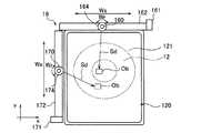
図2は、駐車スペースに設置された送電コイル12及び異物センサ16の状態を模式的に示す上面図である。給電装置100側の送電コイル12は、筐体120の内部に収容された状態で駐車スペースに固定的に配置されている。送電コイル12は、筐体120の表面、具体的にはその上面121(xy平面)と平行する面内において渦巻き状に巻回された構造を有しており、給電時には、筐体120の上面121に相手方のコイルである受電コイル22が向き合うことになる。そのことから、駐車スペースに設置される筐体120の周囲には、当該筐体120の上面121に存在する異物を検出する異物センサ16が配置されている。 FIG. 2 is a top view schematically showing states of the
異物センサ16は、一対のセンサ部160,170と、一対のセンサ部160,170にそれぞれ対応する駆動機構161,171とで構成されている。 The
センサ部160,170は、一定の検知方向Sdに存在する異物を検出するセンサである。センサ部160,170としては、例えば、検知方向Sdに超音波やレーザ(赤外線など)を出射し、異物による反射波又は反射光を受信することにより検知方向Sdに存在する異物(Ob)までの距離を検出する測距センサ等を用いることができる。 The
一方のセンサ部(以下「第1のセンサ部」という)160は、検知方向Sdがy軸方向と一致するように配置されている。この第1のセンサ部160は、x軸方向に延在するガイドレール162に配置されており、このガイドレール162に沿ってスライド移動することができる。駆動機構161は、電動モータやボールネジなどで構成されており、第1のセンサ部160をガイドレール162上で移動させる。 One sensor unit (hereinafter referred to as “first sensor unit”) 160 is arranged so that the detection direction Sd coincides with the y-axis direction. The
この第1のセンサ部160は、検知方向Sdに超音波又はレーザを出射しながら、駆動機構161の動作に応じて可動範囲Ws(送電コイル12の大きさに準じて設定される範囲)を一方から他方にかけて移動する。これにより、第1のセンサ部160は、x軸方向に沿って筐体120の表面121上を走査して、x軸方向に沿って異物を探査することができる。なお、第1のセンサ部160は、筐体120の上面121に存在する厚みの小さい異物を検出することができるように、超音波やレーザが筐体120の上面121に近接するように、その高さ位置が設定されている。 The
また、他方のセンサ部(以下「第2のセンサ部」という)170は、検知方向Sdがx軸方向と一致するように配置されている。この第2のセンサ部170は、y軸方向に延在するガイドレール172に配置されており、このガイドレール172上をスライド移動することができる。駆動機構171は、電動モータやボールネジなどで構成されており、この駆動機構171の駆動量に応じて、第2のセンサ部170をガイドレール172に沿って所定量だけ移動させることができる。 The other sensor unit (hereinafter referred to as “second sensor unit”) 170 is arranged so that the detection direction Sd coincides with the x-axis direction. The
この第2のセンサ部170は、検知方向Sdに超音波又はレーザを出射しながら、駆動機構171の動作に応じて可動範囲Wsを一方から他方にかけて移動する。これより、第2のセンサ部170は、y軸方向に沿って筐体120の表面121上を走査して、y軸方
向に沿って異物を探査することができる。なお、第2のセンサ部170は、筐体120の上面121に存在する厚みの小さい異物を検出することができるように、超音波やレーザが筐体120の上面121に近接するように、その高さ位置が設定されている。The
このように、異物センサ16において、一対のセンサ部160,170は、それぞれの検知方向Sdが交差するように配置されている。したがって、駆動機構161,171を動作させて個々のセンサ部160,170をそれぞれ移動させることで、筐体120の上面121を二次元的に探査することができる。 As described above, in the
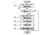
以下、異物センサ16を利用した制御部15による異物検出処理について説明する。ここで、図3は、異物検出処理の詳細を示すフローチャートである。このフローチャートに示す処理は、車両200のバッテリ28の充電に伴う給電装置100から車両200への給電時にその給電動作に先駆けて、あるいは定期的に呼び出され、制御部15の異物検出部150によって実行される。 Hereinafter, the foreign object detection process by the control unit 15 using the
まず、ステップ1(S1)において、異物検出部150は、第1のセンサ部160で異物の検出を行う。具体的には、異物検出部150は、第1のセンサ部160及び駆動機構161を制御して、検知方向Sdに超音波又はレーザを出射しながら、第1のセンサ部160を可動範囲Wsの一方から他方にかけて移動させる。これにより、第1のセンサ部160がx軸方向に沿って超音波又はレーザを走査することで、筐体120の上面121に存在する異物を探査する。この探査において異物が存在する場合、異物検出部150は、第1のセンサ部160からの検出信号に基づいて、y軸方向における異物までの距離と、x軸方向における異物の投影面積(大きさ)とを検出することができる。 First, in step 1 (S1), the foreign
ステップ2(S2)において、異物検出部150は、異物が存在したか否かを判断する。異物がある場合には、ステップ2において肯定判定されるので、ステップ3(S3)に進む。一方、異物がない場合には、ステップ2において否定判定されるので、本ルーチンを終了する。 In step 2 (S2), the foreign
ステップ3(S3)において、異物検出部150は、第2のセンサ部170で異物の検出を行う。具体的には、異物検出部150は、第2のセンサ部170及び駆動機構171を制御して、検知方向Sdに超音波又はレーザを出射しながら、センサ部170を可動範囲Wsの一方から他方にかけて移動させる。これにより、第2のセンサ部160がy軸方向に沿って超音波又はレーザを走査することで、筐体120の上面121に存在する異物を探査する。この探査において異物が存在する場合、異物検出部150は、センサ部170からの検出信号に基づいて、x軸方向における異物までの距離と、y軸方向における異物の投影面積(大きさ)とを検出することができる。 In step 3 (S3), the foreign
ステップ4(S4)において、異物検出部150は、検出された異物の大きさを確定する。異物検出部150は、第1のセンサ部160により得られるx軸方向の異物の投影面積(大きさ)と、第2のセンサ部170により得られるy軸方向の異物の投影面積(大きさ)とによって、異物の大きさを二次元的に認識することできる。 In step 4 (S4), the foreign
ステップ5(S5)において、異物検出部150は、検出された異物の位置を確定する。異物検出部150は、第1のセンサ部160により得られるy軸方向における異物までの距離と、第2のセンサ部170により得られるx軸方向における異物までの距離とによって、異物の位置を二次元的に認識することできる。 In step 5 (S5), the foreign
ステップ6(S6)において、異物検出部150は、異物の大きさ及び異物の位置に基づいて、電力制限量を設定する。この電力制限量は、給電装置100から車両200への
給電時、規定の給電電力に対して出力を制限する割合(制限率)を示すものであり、図4に示すようなマップ等を通じて、異物の大きさ及びその位置から一義的に特定することができる。ここで、図4は、x軸上の任意に点におけるy軸方向上の位置と、異物の大きさ(図中の矢印方向)とに応じた電力制限量を規定するマップであり、異物検出部150は、このようなマップをx軸上の複数の点について保持している。In step 6 (S6), the foreign
磁束により異物が受ける加熱エネルギーは、その材質及び大きさ(磁束方向への投影面積)が同一、送電コイル12の出力条件(周波数)が同一の環境下では、磁束密度の2乗に比例する。すなわち、筐体120の上面121では、送電コイル12に発生した磁束の磁束密度が大きい程、磁束により異物が受ける加熱エネルギー、すなわち、異物の発熱が大きくなることとなる。 The heating energy received by the foreign matter by the magnetic flux is proportional to the square of the magnetic flux density in an environment where the material and size (projected area in the magnetic flux direction) are the same and the output condition (frequency) of the
図5は、コイル中心から半径方向外側に向かった距離と磁束密度との関係を示す説明図である。同図において、Cinは、コイルの最内周に相当する距離Lを示し、Coutは、コイルの最外周に相当する距離Lを示している。同図に示すように、磁束密度は、コイルの面上ほど大きく、また、コイルの面上では、コイルの内周側から外周側にかけて、増加し極大を経て減少するような上に凸となる傾向を有している。したがって、筐体120の上面121では、その位置に応じて、磁束により異物が受ける加熱エネルギー、すなわち、異物の発熱が変位することとなる。 FIG. 5 is an explanatory diagram showing the relationship between the distance from the coil center to the outside in the radial direction and the magnetic flux density. In the drawing, Cin represents a distance L corresponding to the innermost circumference of the coil, and Cout represents a distance L corresponding to the outermost circumference of the coil. As shown in the figure, the magnetic flux density is larger on the surface of the coil, and on the surface of the coil, the magnetic flux density increases from the inner peripheral side to the outer peripheral side of the coil and becomes convex so as to decrease through the maximum. Has a trend. Therefore, on the
また、磁束により異物が受ける加熱エネルギーは、異物の材質が同一、送電コイル12の出力条件(周波数)及び磁束密度が同一の環境下では、異物の大きさに比例する。すなわち、筐体120の上面121では、異物の大きさが大きい程、磁束により異物が受ける加熱エネルギー、すなわち、異物の発熱が大きくなることとなる。 Further, the heating energy received by the foreign matter by the magnetic flux is proportional to the size of the foreign matter in an environment in which the foreign material is the same, the output condition (frequency) of the
このような点に鑑み、本実施形態では、異物の発熱が規定の上限温度以上とならない範囲で給電を行うべく、図4のマップに示すように、異物の大きさ及び位置に応じて、0%から100%の範囲で電力制限量を設定する。そして、制御部15は、センサ114の検出電流に基づいて、インバータ113のスイッチング制御を行い、送電コイル12から供給される電力を制御する。この場合、制御部15は、異物検出部150によって設定される電力制限量を上限として、供給電力が制限されるように電力の制御を行う。 In view of such points, in the present embodiment, in order to perform power supply in a range where the heat generation of the foreign matter does not exceed the specified upper limit temperature, as shown in the map of FIG. The power limit amount is set in the range of 100% to 100%. And the control part 15 performs switching control of the
なお、異物の材質(透磁率)によって加熱エネルギーが異なることから、発熱により最も高温となる材質である「鉄」を異物として、電力制限量を検討することが好ましい。 In addition, since the heating energy differs depending on the material (magnetic permeability) of the foreign material, it is preferable to consider the power limit amount by using “iron” which is the material having the highest temperature due to heat generation as a foreign material.
このように本実施形態において、非接触給電システムは、送電コイル12を内部に収容して所定の目的箇所に設置される筐体120と、この筐体120の表面に存在する異物を検出する検出ユニットとを有している。ここで、検出ユニットは、異物に対して感応する検知方向Sdがそれぞれ交差するように配置された一対のセンサ部160,170と、一対のセンサ部160,170からの信号に基づいて異物を検出する異物検出部150と、を有している。そして、異物検出部150は、筐体120の上面121に存在する異物について、その大きさを検出する。 As described above, in the present embodiment, the non-contact power feeding system includes the
かかる構成によれば、一対のセンサ部160,170をそれぞれの検知方向Sdが交差するように配置したことで、筐体120の上面121を二次元的に探査することができる。そのため、一対のセンサ部160,170のそれぞれの検出情報を参照することで、その上面121における異物を二次元的に捉えることができるので、その大きさを適切に検出することができる。 According to such a configuration, the
また、本実施形態によれば、一対のセンサ部160,170のそれぞれの検出情報を参
照することで、その上面121における異物を二次元的に捉えることができるので、その位置を適切に検出することができる。In addition, according to the present embodiment, by referring to the detection information of the pair of
また、本実施形態において、異物検出部150は、筐体120の上面121上に存在する異物の大きさと位置とに基づいて、送電コイル12と受電コイル22との間で供給される電力について電力制限を行う。 Further, in the present embodiment, the foreign
かかる構成によれば、異物に大きさ及び位置に応じて電力制限量が設定されることで、給電時の電力に制限を課すことができるので、充電に伴う異物の発熱が所定の上限温度以上に到達してしまうといった事態を抑制することができる。また、電力制限を行うことで、異物が存在しても可能な範囲で電力供給を実行することができるので、異物の存在によって一律に電力供給が禁止されるといった事態を抑制することができる。 According to such a configuration, since the power limit amount is set according to the size and position of the foreign object, it is possible to impose a limit on the power during power supply. It is possible to suppress a situation such as reaching. In addition, by performing power limitation, power supply can be executed as much as possible even if foreign matter is present, so that a situation where power supply is uniformly prohibited due to the presence of foreign matter can be suppressed.
また、本実施形態において、一対のセンサ160,170は、互いに交差する二軸(xy軸)上に配置されており、この配置された軸上をそれぞれ移動可動に構成されている。 In the present embodiment, the pair of
かかる構成によれば、一対のセンサ160,170が交差する二軸(xy軸)を移動することで、筐体120の上面121を二次元的に探査することができる。これにより、異物の大きさ、さらにはその位置を二次元的に検出することができる。 According to this configuration, the
また、本実施形態において、異物センサ16をなす一対のセンサ160,170は、非接触で電力の供給を行うべく送電コイル12及び受電コイル22が対峙した際に、鉛直下方に配置される送電コイル12を収容する筐体120に配置されている。 In the present embodiment, the pair of
かかる構成によれば、鉛直下方に配置される送電コイル12では、これと向き合う関係にある受電コイル22と比較して、その筐体120の上面121に異物が存在し易い。これにより、異物の検出を有効に行うことができる。 According to this configuration, in the
なお、本実施形態では、充電制限量を設定すると、その後異物検出を行っていないが、上述したフローチャートを繰り返し実行し、筐体120の上面121から異物が取り除かれたことを条件に、充電制限量をリセットしてもよい。 In this embodiment, when the charge restriction amount is set, foreign object detection is not performed after that. However, the above-described flowchart is repeatedly executed, and charge restriction is performed on the condition that the foreign object is removed from the
(第2の実施形態)
図6は、第2の実施形態に係る異物センサ16の構成を模式的に示す説明図である。第2の実施形態に係る異物センサ16が、第1の実施形態のそれと相違する点は、筐体120の上面121を二次元的に探査する手法である。以下、第1の実施形態と共通する構成については説明を省略することとし、相違点を中心に説明を行う。(Second Embodiment)
FIG. 6 is an explanatory diagram schematically showing the configuration of the
第2の実施形態に係る異物センサ16は、一対のセンサ部160,170と、一対のセンサ部160,170にそれぞれ対応する駆動機構164,174とで構成されている。 The
センサ部160,170は、第1の実施形態と同様、検知方向Sdに存在する異物を検出するセンサであり、測距センサ等を用いることができる。 Similar to the first embodiment, the
第1のセンサ部160は、筐体120の上面121と平行する二次元平面を規定するx軸において、送電コイル12の中心と対応する位置に配置され、その検知方向Sdを少なくともy軸方向と一致させることができるようになっている。この第1のセンサ部160は、駆動機構164の筐体の上部に取り付けてあり、xy平面と直交する軸(本実施形態では鉛直軸)を中心として回動することができる。駆動機構164は、電動モータやギヤなどで構成されており、この駆動機構164の駆動量に応じて、第1のセンサ部160を
所定量だけ回転させることができる。The
この第1のセンサ部160は、検知方向Sdに超音波又はレーザを出射しながら、駆動機構164の動作に応じて可動範囲Wr(送電コイル12の大きさに準じて設定される範囲)を一方から他方にかけて回動し、これより、円周方向に沿って筐体120の表面121上を走査して、異物を探査することができる。 The
また、第2のセンサ部170は、y軸において、送電コイル12の中心と対応する位置に配置され、その検知方向Sdを少なくともx軸方向と一致させることができるようになっている。この第2のセンサ部170は、駆動機構174の筐体の上部に取り付けてあり、xy平面と直交する軸(本実施形態では鉛直軸)を中心として回動することができる。駆動機構174は、電動モータやギヤなどで構成されており、この駆動機構174の駆動量に応じて、第2のセンサ部170を所定量だけ回転させることができる。 Moreover, the
この第2のセンサ部170は、検知方向Sdに超音波又はレーザを出射しながら、駆動機構174の動作に応じて可動範囲Wr(送電コイル12の大きさに準じて設定される範囲)を一方から他方にかけて回動し、これより、円周方向に沿って筐体120の表面121上を走査して、異物を探査することができる。 The
このように、異物センサ16において、一対のセンサ部160,170は、それぞれの検知方向Sdが交差するように配置されており、駆動機構164,174を動作させて個々のセンサ部160,170をそれぞれ回動させることで、筐体120の上面121を二次元的に探査することができる。 As described above, in the
(第3の実施形態)
図7は、第3の実施形態に係る異物センサ16の構成を模式的に示す説明図である。第3の実施形態に係る異物センサ16が、第1の実施形態のそれと相違する点は、筐体120の上面121を二次元的に探査する手法である。以下、第1の実施形態と共通する構成については説明を省略することとし、相違点を中心に説明を行う。(Third embodiment)
FIG. 7 is an explanatory diagram schematically showing the configuration of the
第3の実施形態に係る異物センサ16は、前述の第1の実施形態と第2の実施形態と組み合わせたものであり、一対のセンサ部160,170と、それぞれのセンサ部160,170に対応する駆動機構161,164,171,174とで構成されている。 The
この場合、第1のセンサ部160は、検知方向Sdに超音波又はレーザを出射しながら、駆動機構161の動作に応じて可動範囲Wsを一方から他方にかけて移動し、これより、x軸方向に沿って筐体120の表面121上を走査して、異物を探査することができる。また、第1のセンサ部160は、必要に応じて、駆動機構164の動作に伴い可動範囲Wsを一方から他方にかけて回動し、これより、円周方向に沿って筐体120の表面121上を走査して、異物を探査することができる。 In this case, the
一方、第2のセンサ部170は、検知方向Sdに超音波又はレーザを出射しながら、駆動機構171の動作に応じて可動範囲Wsを一方から他方にかけて移動し、これより、y軸方向に沿って筐体120の表面121上を走査して、異物を探査することができる。また、第2のセンサ部170は、必要に応じて、駆動機構174の動作に伴い可動範囲Wsを一方から他方にかけて回動し、これより、円周方向に沿って筐体120の表面121上を走査して、異物を探査することができる。 On the other hand, the
このように、異物センサ16において、一対のセンサ部160,170は、それぞれの検知方向Sdが交差するように配置されており、駆動機構164,174を動作させて個
々のセンサ部160,170をそれぞれ移動及び回動させることで、筐体120の上面121を二次元的に探査することができる。As described above, in the
このように、異物センサ16において、一対のセンサ部160,170は、それぞれの検知方向Sdが交差するように配置されており、駆動機構161,171又は駆動機構164,174を動作させて個々のセンサ部160,170をそれぞれ移動又は回動させることで、筐体120の上面121を二次元的に探査することができる。 As described above, in the
また、図7に示すように、xy軸方向への移動と、回動とを組み合わせするとにより、一の異物の背後に他の異物が存在するようなケースでも、他方のセンサ部160,170を移動又は回動させることにより、その背後に存在する異物を有効に検出することができる。 Further, as shown in FIG. 7, by combining movement in the xy-axis direction and rotation, the
なお、上述の各実施形態では、地上側に配置される送電コイル12を収容する筐体120に異物センサ16を適用している。例えば、受電コイル22が車両200の天井に配置され、これに対峙するように送電コイル12が配置されるような形態であれば、受電コイル22を収容する筐体に異物センサ16を適用してもよい。もっとも、異物を検出する点に観点に鑑みれば、異物センサ16は、互いに対峙する一対のコイルについて、個々のコイルを収容する筐体のそれぞれに適用してもよい。 In each of the above-described embodiments, the
また、非接触給電システムの車両200側のユニットは電気自動車に搭載されるが、ハイブリッド車両等の車両でもよい。 The unit on the
以上、本発明の実施形態にかかる非接触充電装置について説明したが、本発明は上述した実施形態に限定されることなく、その発明の範囲内において種々の変形が可能であることはいうまでもない。 As mentioned above, although the non-contact charging device concerning embodiment of this invention was demonstrated, this invention is not limited to embodiment mentioned above, It cannot be overemphasized that various deformation | transformation are possible within the scope of the invention. Absent.
100 給電装置
11 電力制御部
12 送電コイル
120 筐体
121 上面
14 無線通信部
15 制御部
150 異物検出部
16 異物センサ
160 センサ部
161 駆動機構
162 ガイドレール
164 駆動機構
170 センサ部
171 駆動機構
172 ガイドレール
174 駆動機構
200 車両
22 受電コイル
24 無線通信部
25 充電制御部
26 整流部
27 リレー部
28 バッテリ
29 インバータ
30 モータ
32 通知部DESCRIPTION OF
Claims (5)
Translated fromJapanese前記第1のコイル又は第2のコイルを内部に収容し、所定の目的箇所に設置される筐体と、
前記筐体の表面に存在する異物を検出する検出ユニットと、を有し、
前記検出ユニットは、
異物に対する検知方向がそれぞれ交差するように配置されて、前記筐体の表面を二次元的に探査する一対のセンサ部と、
前記一対のセンサ部からの信号に基づいて前記異物を検出する異物検出部と、を有し、
前記異物検出部は、前記筐体の表面に存在する異物について、その大きさを検出することを特徴とする非接触給電装置。In a non-contact power feeding device that performs non-contact power supply between the first coil and the second coil by magnetic coupling,
A housing that houses the first coil or the second coil and is installed at a predetermined destination;
A detection unit for detecting foreign matter present on the surface of the housing,
The detection unit is
A pair of sensor units that are arranged so that the detection directions with respect to the foreign objects intersect with each other and probe the surface of the housing two-dimensionally;
A foreign matter detection unit that detects the foreign matter based on signals from the pair of sensor units,
The non-contact power feeding apparatus according to claim 1, wherein the foreign matter detection unit detects the size of the foreign matter existing on the surface of the casing.
Priority Applications (1)
| Application Number | Priority Date | Filing Date | Title |
|---|---|---|---|
| JP2012268928AJP2014112063A (en) | 2012-10-31 | 2012-12-10 | Non-contact power supply device |
Applications Claiming Priority (3)
| Application Number | Priority Date | Filing Date | Title |
|---|---|---|---|
| JP2012239756 | 2012-10-31 | ||
| JP2012239756 | 2012-10-31 | ||
| JP2012268928AJP2014112063A (en) | 2012-10-31 | 2012-12-10 | Non-contact power supply device |
Publications (1)
| Publication Number | Publication Date |
|---|---|
| JP2014112063Atrue JP2014112063A (en) | 2014-06-19 |
Family
ID=51169290
Family Applications (1)
| Application Number | Title | Priority Date | Filing Date |
|---|---|---|---|
| JP2012268928APendingJP2014112063A (en) | 2012-10-31 | 2012-12-10 | Non-contact power supply device |
Country Status (1)
| Country | Link |
|---|---|
| JP (1) | JP2014112063A (en) |
Cited By (25)
| Publication number | Priority date | Publication date | Assignee | Title |
|---|---|---|---|---|
| WO2015068476A1 (en)* | 2013-11-06 | 2015-05-14 | 本田技研工業株式会社 | Non-contact power transmission system |
| JP2019510449A (en)* | 2015-12-29 | 2019-04-11 | エナージャス コーポレイション | Radar motion detection using step frequency in wireless power transfer system |
| US10965164B2 (en) | 2012-07-06 | 2021-03-30 | Energous Corporation | Systems and methods of wirelessly delivering power to a receiver device |
| US10985617B1 (en) | 2019-12-31 | 2021-04-20 | Energous Corporation | System for wirelessly transmitting energy at a near-field distance without using beam-forming control |
| US10992185B2 (en) | 2012-07-06 | 2021-04-27 | Energous Corporation | Systems and methods of using electromagnetic waves to wirelessly deliver power to game controllers |
| US11011942B2 (en) | 2017-03-30 | 2021-05-18 | Energous Corporation | Flat antennas having two or more resonant frequencies for use in wireless power transmission systems |
| US11018779B2 (en) | 2019-02-06 | 2021-05-25 | Energous Corporation | Systems and methods of estimating optimal phases to use for individual antennas in an antenna array |
| US11139699B2 (en) | 2019-09-20 | 2021-10-05 | Energous Corporation | Classifying and detecting foreign objects using a power amplifier controller integrated circuit in wireless power transmission systems |
| US11342798B2 (en) | 2017-10-30 | 2022-05-24 | Energous Corporation | Systems and methods for managing coexistence of wireless-power signals and data signals operating in a same frequency band |
| US11355966B2 (en) | 2019-12-13 | 2022-06-07 | Energous Corporation | Charging pad with guiding contours to align an electronic device on the charging pad and efficiently transfer near-field radio-frequency energy to the electronic device |
| US11381118B2 (en) | 2019-09-20 | 2022-07-05 | Energous Corporation | Systems and methods for machine learning based foreign object detection for wireless power transmission |
| US11411441B2 (en) | 2019-09-20 | 2022-08-09 | Energous Corporation | Systems and methods of protecting wireless power receivers using multiple rectifiers and establishing in-band communications using multiple rectifiers |
| US11462949B2 (en) | 2017-05-16 | 2022-10-04 | Wireless electrical Grid LAN, WiGL Inc | Wireless charging method and system |
| US11502551B2 (en) | 2012-07-06 | 2022-11-15 | Energous Corporation | Wirelessly charging multiple wireless-power receivers using different subsets of an antenna array to focus energy at different locations |
| US11539243B2 (en) | 2019-01-28 | 2022-12-27 | Energous Corporation | Systems and methods for miniaturized antenna for wireless power transmissions |
| US11799324B2 (en) | 2020-04-13 | 2023-10-24 | Energous Corporation | Wireless-power transmitting device for creating a uniform near-field charging area |
| US11831361B2 (en) | 2019-09-20 | 2023-11-28 | Energous Corporation | Systems and methods for machine learning based foreign object detection for wireless power transmission |
| US11916398B2 (en) | 2021-12-29 | 2024-02-27 | Energous Corporation | Small form-factor devices with integrated and modular harvesting receivers, and shelving-mounted wireless-power transmitters for use therewith |
| US12057715B2 (en) | 2012-07-06 | 2024-08-06 | Energous Corporation | Systems and methods of wirelessly delivering power to a wireless-power receiver device in response to a change of orientation of the wireless-power receiver device |
| US12074460B2 (en) | 2017-05-16 | 2024-08-27 | Wireless Electrical Grid Lan, Wigl Inc. | Rechargeable wireless power bank and method of using |
| US12142939B2 (en) | 2022-05-13 | 2024-11-12 | Energous Corporation | Integrated wireless-power-transmission platform designed to operate in multiple bands, and multi-band antennas for use therewith |
| US12155231B2 (en) | 2019-04-09 | 2024-11-26 | Energous Corporation | Asymmetric spiral antennas for wireless power transmission and reception |
| US12224599B2 (en) | 2020-08-12 | 2025-02-11 | Energous Corporation | Systems and methods for secure wireless transmission of power using unidirectional communication signals from a wireless-power-receiving device |
| US12306285B2 (en) | 2020-12-01 | 2025-05-20 | Energous Corporation | Systems and methods for using one or more sensors to detect and classify objects in a keep-out zone of a wireless-power transmission field, and antennas with integrated sensor arrangements |
| US12431735B2 (en) | 2019-09-20 | 2025-09-30 | Energous Corporation | Asymmetric spiral antennas with parasitic elements for wireless power transmission |
- 2012
- 2012-12-10JPJP2012268928Apatent/JP2014112063A/enactivePending
Cited By (41)
| Publication number | Priority date | Publication date | Assignee | Title |
|---|---|---|---|---|
| US12057715B2 (en) | 2012-07-06 | 2024-08-06 | Energous Corporation | Systems and methods of wirelessly delivering power to a wireless-power receiver device in response to a change of orientation of the wireless-power receiver device |
| US11652369B2 (en) | 2012-07-06 | 2023-05-16 | Energous Corporation | Systems and methods of determining a location of a receiver device and wirelessly delivering power to a focus region associated with the receiver device |
| US10965164B2 (en) | 2012-07-06 | 2021-03-30 | Energous Corporation | Systems and methods of wirelessly delivering power to a receiver device |
| US12166363B2 (en) | 2012-07-06 | 2024-12-10 | Energous Corporation | System and methods of using electromagnetic waves to wirelessly deliver power to security cameras and adjusting wireless delivery of power to the security cameras as they move |
| US10992185B2 (en) | 2012-07-06 | 2021-04-27 | Energous Corporation | Systems and methods of using electromagnetic waves to wirelessly deliver power to game controllers |
| US11502551B2 (en) | 2012-07-06 | 2022-11-15 | Energous Corporation | Wirelessly charging multiple wireless-power receivers using different subsets of an antenna array to focus energy at different locations |
| WO2015068476A1 (en)* | 2013-11-06 | 2015-05-14 | 本田技研工業株式会社 | Non-contact power transmission system |
| JP2019510449A (en)* | 2015-12-29 | 2019-04-11 | エナージャス コーポレイション | Radar motion detection using step frequency in wireless power transfer system |
| US11011942B2 (en) | 2017-03-30 | 2021-05-18 | Energous Corporation | Flat antennas having two or more resonant frequencies for use in wireless power transmission systems |
| US12074460B2 (en) | 2017-05-16 | 2024-08-27 | Wireless Electrical Grid Lan, Wigl Inc. | Rechargeable wireless power bank and method of using |
| US11462949B2 (en) | 2017-05-16 | 2022-10-04 | Wireless electrical Grid LAN, WiGL Inc | Wireless charging method and system |
| US11342798B2 (en) | 2017-10-30 | 2022-05-24 | Energous Corporation | Systems and methods for managing coexistence of wireless-power signals and data signals operating in a same frequency band |
| US11817721B2 (en) | 2017-10-30 | 2023-11-14 | Energous Corporation | Systems and methods for managing coexistence of wireless-power signals and data signals operating in a same frequency band |
| US11539243B2 (en) | 2019-01-28 | 2022-12-27 | Energous Corporation | Systems and methods for miniaturized antenna for wireless power transmissions |
| US11018779B2 (en) | 2019-02-06 | 2021-05-25 | Energous Corporation | Systems and methods of estimating optimal phases to use for individual antennas in an antenna array |
| US11784726B2 (en) | 2019-02-06 | 2023-10-10 | Energous Corporation | Systems and methods of estimating optimal phases to use for individual antennas in an antenna array |
| US11463179B2 (en) | 2019-02-06 | 2022-10-04 | Energous Corporation | Systems and methods of estimating optimal phases to use for individual antennas in an antenna array |
| US12155231B2 (en) | 2019-04-09 | 2024-11-26 | Energous Corporation | Asymmetric spiral antennas for wireless power transmission and reception |
| US11799328B2 (en) | 2019-09-20 | 2023-10-24 | Energous Corporation | Systems and methods of protecting wireless power receivers using surge protection provided by a rectifier, a depletion mode switch, and a coupling mechanism having multiple coupling locations |
| US11139699B2 (en) | 2019-09-20 | 2021-10-05 | Energous Corporation | Classifying and detecting foreign objects using a power amplifier controller integrated circuit in wireless power transmission systems |
| US12431735B2 (en) | 2019-09-20 | 2025-09-30 | Energous Corporation | Asymmetric spiral antennas with parasitic elements for wireless power transmission |
| US12418327B2 (en) | 2019-09-20 | 2025-09-16 | Energous Corporation | Systems and methods for machine learning zone-based foreign object detection for wireless power transmission |
| US12301020B2 (en) | 2019-09-20 | 2025-05-13 | Energous Corporation | Systems and methods of establishing in-band communications using a communication criterion |
| US11411441B2 (en) | 2019-09-20 | 2022-08-09 | Energous Corporation | Systems and methods of protecting wireless power receivers using multiple rectifiers and establishing in-band communications using multiple rectifiers |
| US11831361B2 (en) | 2019-09-20 | 2023-11-28 | Energous Corporation | Systems and methods for machine learning based foreign object detection for wireless power transmission |
| US11381118B2 (en) | 2019-09-20 | 2022-07-05 | Energous Corporation | Systems and methods for machine learning based foreign object detection for wireless power transmission |
| US12074459B2 (en) | 2019-09-20 | 2024-08-27 | Energous Corporation | Classifying and detecting foreign objects using a power amplifier controller integrated circuit in wireless power transmission systems |
| US11715980B2 (en) | 2019-09-20 | 2023-08-01 | Energous Corporation | Classifying and detecting foreign objects using a power amplifier controller integrated circuit in wireless power transmission systems |
| US12218519B2 (en) | 2019-12-13 | 2025-02-04 | Energous Corporation | Charging pad with guiding contours to align an electronic device on the charging pad |
| US11355966B2 (en) | 2019-12-13 | 2022-06-07 | Energous Corporation | Charging pad with guiding contours to align an electronic device on the charging pad and efficiently transfer near-field radio-frequency energy to the electronic device |
| US12100971B2 (en) | 2019-12-31 | 2024-09-24 | Energous Corporation | Systems and methods for determining a keep-out zone of a wireless power transmitter |
| US10985617B1 (en) | 2019-12-31 | 2021-04-20 | Energous Corporation | System for wirelessly transmitting energy at a near-field distance without using beam-forming control |
| US11817719B2 (en) | 2019-12-31 | 2023-11-14 | Energous Corporation | Systems and methods for controlling and managing operation of one or more power amplifiers to optimize the performance of one or more antennas |
| US11411437B2 (en) | 2019-12-31 | 2022-08-09 | Energous Corporation | System for wirelessly transmitting energy without using beam-forming control |
| US12348055B2 (en) | 2020-04-13 | 2025-07-01 | Energous Corporation | Wireless-power transmitting device for creating a uniform near-field charging area |
| US11799324B2 (en) | 2020-04-13 | 2023-10-24 | Energous Corporation | Wireless-power transmitting device for creating a uniform near-field charging area |
| US12224599B2 (en) | 2020-08-12 | 2025-02-11 | Energous Corporation | Systems and methods for secure wireless transmission of power using unidirectional communication signals from a wireless-power-receiving device |
| US12306285B2 (en) | 2020-12-01 | 2025-05-20 | Energous Corporation | Systems and methods for using one or more sensors to detect and classify objects in a keep-out zone of a wireless-power transmission field, and antennas with integrated sensor arrangements |
| US11916398B2 (en) | 2021-12-29 | 2024-02-27 | Energous Corporation | Small form-factor devices with integrated and modular harvesting receivers, and shelving-mounted wireless-power transmitters for use therewith |
| US12413097B2 (en) | 2021-12-29 | 2025-09-09 | Energous Corporation | Small form-factor devices with integrated and modular harvesting receivers, and shelving-mounted wireless-power transmitters for use therewith |
| US12142939B2 (en) | 2022-05-13 | 2024-11-12 | Energous Corporation | Integrated wireless-power-transmission platform designed to operate in multiple bands, and multi-band antennas for use therewith |
Similar Documents
| Publication | Publication Date | Title |
|---|---|---|
| JP2014112063A (en) | Non-contact power supply device | |
| JP6369304B2 (en) | Wireless power transmission system | |
| RU2554103C1 (en) | Non-contact power supply device | |
| EP3234639B1 (en) | Radar system with several transceivers for monitoring and detecting targets within a surveillance area | |
| JP5838262B2 (en) | Power transmission equipment | |
| EP3207402B1 (en) | Systems, methods, and apparatus for living object protection in wireless power transfer applications | |
| JP5747863B2 (en) | Vehicle, power receiving device, power transmitting device, and non-contact power feeding system | |
| US9180782B2 (en) | Non-contact power receiving apparatus, non-contact power transmitting apparatus, and non-contact power transmitting/receiving system | |
| JP6019103B2 (en) | Antenna alignment and vehicle guidance for wireless charging of electric vehicles | |
| JP7122688B2 (en) | Control method for power transmission device, foreign object detection method, and power transmission device in wireless power transmission system | |
| WO2013035853A1 (en) | Non-contact power supply device for use in mobile body | |
| JP5641027B2 (en) | Power transmission device, vehicle, and non-contact power feeding system | |
| CN103620913A (en) | power transmission system | |
| JP6566131B2 (en) | Method for detecting coil position of non-contact power feeding system and non-contact power feeding system | |
| JP2016226073A (en) | Wireless power transmission system | |
| JP2015008552A (en) | Non-contact charger | |
| WO2012090341A1 (en) | Power control device for contactless charging device | |
| JP2016041009A (en) | Power transmission apparatus | |
| JP2016103933A (en) | Vehicle power supply equipment | |
| JP2019071762A (en) | Method for controlling power transmitting device for radio power transmission system, method for detecting foreign matter and power transmitting device | |
| JP2016034169A (en) | Non-contact power supply device and non-contact power supply system | |
| JP2016106512A (en) | Non-contact power feeding device | |
| JP2012152075A (en) | Power transmission device | |
| JP2022102641A (en) | Wireless power receiving equipment, wireless power transmission equipment, and wireless power transmission system | |
| JP2014113018A (en) | Non-contact power supply device |