JP2014111949A - Coolant pipe joint structure - Google Patents
Coolant pipe joint structureDownload PDFInfo
- Publication number
- JP2014111949A JP2014111949AJP2012262696AJP2012262696AJP2014111949AJP 2014111949 AJP2014111949 AJP 2014111949AJP 2012262696 AJP2012262696 AJP 2012262696AJP 2012262696 AJP2012262696 AJP 2012262696AJP 2014111949 AJP2014111949 AJP 2014111949A
- Authority
- JP
- Japan
- Prior art keywords
- cap nut
- pipe
- peripheral surface
- compression deformation
- joint body
- Prior art date
- Legal status (The legal status is an assumption and is not a legal conclusion. Google has not performed a legal analysis and makes no representation as to the accuracy of the status listed.)
- Granted
Links
- 239000002826coolantSubstances0.000titleabstract4
- 229910052782aluminiumInorganic materials0.000claimsabstractdescription78
- XAGFODPZIPBFFR-UHFFFAOYSA-NaluminiumChemical compound[Al]XAGFODPZIPBFFR-UHFFFAOYSA-N0.000claimsabstractdescription78
- 230000006835compressionEffects0.000claimsabstractdescription73
- 238000007906compressionMethods0.000claimsabstractdescription73
- 230000002093peripheral effectEffects0.000claimsdescription81
- RYGMFSIKBFXOCR-UHFFFAOYSA-NCopperChemical compound[Cu]RYGMFSIKBFXOCR-UHFFFAOYSA-N0.000claimsdescription56
- 229910052802copperInorganic materials0.000claimsdescription56
- 239000010949copperSubstances0.000claimsdescription56
- 239000003507refrigerantSubstances0.000claimsdescription29
- 239000000463materialSubstances0.000claimsdescription12
- 230000001737promoting effectEffects0.000claimsdescription3
- 238000007789sealingMethods0.000description25
- 238000005260corrosionMethods0.000description14
- 230000007797corrosionEffects0.000description14
- 230000009471actionEffects0.000description10
- 229910052751metalInorganic materials0.000description10
- 239000002184metalSubstances0.000description10
- 239000004033plasticSubstances0.000description9
- 229920005989resinPolymers0.000description8
- 239000011347resinSubstances0.000description8
- 229910001369BrassInorganic materials0.000description6
- 239000010951brassSubstances0.000description6
- 238000000034methodMethods0.000description6
- 230000008569processEffects0.000description6
- 230000003014reinforcing effectEffects0.000description6
- 230000004323axial lengthEffects0.000description4
- -1brassChemical compound0.000description4
- 150000002739metalsChemical class0.000description4
- 230000004048modificationEffects0.000description4
- 238000012986modificationMethods0.000description4
- 239000003566sealing materialSubstances0.000description4
- 239000010935stainless steelSubstances0.000description4
- 229910001220stainless steelInorganic materials0.000description4
- 229910000838Al alloyInorganic materials0.000description2
- 229910045601alloyInorganic materials0.000description2
- 239000000956alloySubstances0.000description2
- 230000007423decreaseEffects0.000description2
- 238000006073displacement reactionMethods0.000description2
- 239000003822epoxy resinSubstances0.000description2
- 230000006872improvementEffects0.000description2
- 238000010422paintingMethods0.000description2
- 238000007747platingMethods0.000description2
- 229920000647polyepoxidePolymers0.000description2
- 239000004810polytetrafluoroethyleneSubstances0.000description2
- 229920001343polytetrafluoroethylenePolymers0.000description2
- 238000005507sprayingMethods0.000description2
- 230000004044responseEffects0.000description1
Images


Classifications
- F—MECHANICAL ENGINEERING; LIGHTING; HEATING; WEAPONS; BLASTING
- F16—ENGINEERING ELEMENTS AND UNITS; GENERAL MEASURES FOR PRODUCING AND MAINTAINING EFFECTIVE FUNCTIONING OF MACHINES OR INSTALLATIONS; THERMAL INSULATION IN GENERAL
- F16L—PIPES; JOINTS OR FITTINGS FOR PIPES; SUPPORTS FOR PIPES, CABLES OR PROTECTIVE TUBING; MEANS FOR THERMAL INSULATION IN GENERAL
- F16L19/00—Joints in which sealing surfaces are pressed together by means of a member, e.g. a swivel nut, screwed on, or into, one of the joint parts
- F16L19/06—Joints in which sealing surfaces are pressed together by means of a member, e.g. a swivel nut, screwed on, or into, one of the joint parts in which radial clamping is obtained by wedging action on non-deformed pipe ends
- F16L19/065—Joints in which sealing surfaces are pressed together by means of a member, e.g. a swivel nut, screwed on, or into, one of the joint parts in which radial clamping is obtained by wedging action on non-deformed pipe ends the wedging action being effected by means of a ring
- F—MECHANICAL ENGINEERING; LIGHTING; HEATING; WEAPONS; BLASTING
- F16—ENGINEERING ELEMENTS AND UNITS; GENERAL MEASURES FOR PRODUCING AND MAINTAINING EFFECTIVE FUNCTIONING OF MACHINES OR INSTALLATIONS; THERMAL INSULATION IN GENERAL
- F16L—PIPES; JOINTS OR FITTINGS FOR PIPES; SUPPORTS FOR PIPES, CABLES OR PROTECTIVE TUBING; MEANS FOR THERMAL INSULATION IN GENERAL
- F16L19/00—Joints in which sealing surfaces are pressed together by means of a member, e.g. a swivel nut, screwed on, or into, one of the joint parts
- F16L19/08—Joints in which sealing surfaces are pressed together by means of a member, e.g. a swivel nut, screwed on, or into, one of the joint parts with metal rings which bite into the wall of the pipe
- F16L19/10—Joints in which sealing surfaces are pressed together by means of a member, e.g. a swivel nut, screwed on, or into, one of the joint parts with metal rings which bite into the wall of the pipe the profile of the ring being altered
- F16L19/12—Joints in which sealing surfaces are pressed together by means of a member, e.g. a swivel nut, screwed on, or into, one of the joint parts with metal rings which bite into the wall of the pipe the profile of the ring being altered with additional sealing means
Landscapes
- Engineering & Computer Science (AREA)
- General Engineering & Computer Science (AREA)
- Mechanical Engineering (AREA)
- Joints With Pressure Members (AREA)
- Rigid Pipes And Flexible Pipes (AREA)
- Non-Disconnectible Joints And Screw-Threaded Joints (AREA)
Abstract
Description
Translated fromJapanese本発明は、冷媒用管継手構造に関する。 The present invention relates to a pipe joint structure for refrigerant.
管継手の一種として、フレア継手が広く用いられている(例えば、特許文献1参照)。
一般に、図11に示すように、雄ネジ付き継手本体30のテーパ面31と、継手本体30の雄ネジ32に螺着される袋ナット33のテーパ面34の間に、銅製パイプ35の端部を拡径テーパ状に塑性加工して成るフレア端部37を、挟持させて圧接力により密封する構造である。A flare joint is widely used as a kind of pipe joint (see, for example, Patent Document 1).
In general, as shown in FIG. 11, the end portion of the
しかし、近年、パイプ35の材質として、高価で重い銅より、安価で軽いアルミニウムを用いたいという要望が強い。パイプ35がアルミニウムから成る場合、フレア加工を施すのが困難であるという欠点があった。勿論、銅管についても、上記フレア加工を現場で行う必要があるため、配管作業能率アップを阻害しているという欠点があった。また、それらの問題を回避するために種々の管継手構造が提案されているが、部品点数が多く、複雑な形状の部品を必要とし、組立時に手間がかかるという欠点があった。 However, in recent years, there is a strong demand to use cheap and light aluminum as a material for the
解決しようとする課題は、アルミニウム管にフレア加工を施すのが困難だという点である。あるいは、銅管にあっても、フレア加工が配管作業現場の作業能率アップを阻害していた点である。また、それらの問題を回避するための種々の管継手構造では、部品点数が多く、複雑な形状の部品を必要とし、組立時に手間がかかる点である。 The problem to be solved is that it is difficult to flare the aluminum tube. Or even if it exists in a copper pipe, it is the point to which the flare process had inhibited the work efficiency improvement of the piping work site. Moreover, in various pipe joint structures for avoiding these problems, the number of parts is large and parts having complicated shapes are required, which takes time during assembly.
本発明に係る冷媒用管継手構造は、雄ネジ付き継手本体と、該継手本体の雄ネジに螺着される袋ナットと、を備え、アルミニウム管を接続する冷媒用管継手構造に於て、上記袋ナットの内部収納空間に収納されると共に、外周面に凹周溝を有し、上記袋ナットと上記継手本体の雄ネジを螺着させる際に上記継手本体と上記袋ナットからアキシャル方向の圧縮力を受けて、凹周溝底薄壁部がラジアル内方向へ塑性変形して、挿入されている上記アルミニウム管の外周面側から食い込んで抜止めする圧縮変形用スリーブを有するものである。
また、上記圧縮変形用スリーブは、アルミニウム又はアルミニウム層を被覆した銅から成るものである。The refrigerant pipe joint structure according to the present invention comprises a joint body with a male thread and a cap nut screwed to the male thread of the joint body, and the refrigerant pipe joint structure for connecting an aluminum pipe, It is housed in the internal storage space of the cap nut and has a concave circumferential groove on the outer peripheral surface. When the cap nut and the male screw of the joint body are screwed together, the joint body and the cap nut are axially moved. In response to the compressive force, the concave circumferential groove bottom thin wall portion is plastically deformed radially inward, and has a compression deformation sleeve that bites in from the outer peripheral surface side of the inserted aluminum tube and prevents it.
The compression deformation sleeve is made of aluminum or copper coated with an aluminum layer.
また、雄ネジ付き継手本体と、該継手本体の雄ネジに螺着される袋ナットと、を備え、銅管を接続する冷媒用管継手構造に於て、上記袋ナットの内部収納空間に収納されると共に、外周面に凹周溝を有し、上記袋ナットと上記継手本体の雄ネジを螺着させる際に上記継手本体と上記袋ナットからアキシャル方向の圧縮力を受けて、凹周溝底薄壁部がラジアル内方向へ塑性変形して、挿入されている上記銅管の外周面側から食い込んで抜止めする圧縮変形用スリーブを有するものである。
また、上記圧縮変形用スリーブは、銅から成るものである。
また、上記圧縮変形用スリーブの内周面に予め一体にシール層を有して、上記食い込みの際に密封状態となるように構成したものである。
また、上記圧縮変形用スリーブが内周面にシール溝を有し、該シール溝内にシール材を内装したものである。
また、上記袋ナットの内周面と、上記圧縮変形用スリーブの外周面との間に、相対的回転滑り助長用円筒状カバー部材を介在させた構成とするも好ましい。In addition, in a refrigerant pipe joint structure for connecting a copper pipe, a joint body with a male thread and a cap nut screwed to the male thread of the joint body are stored in the internal storage space of the cap nut. And having a concave groove on the outer peripheral surface, and receiving a compressive force in the axial direction from the joint main body and the cap nut when screwing the male screw of the cap nut and the joint main body, The thin bottom wall portion is plastically deformed radially inward, and has a compression deformation sleeve that bites from the outer peripheral surface side of the inserted copper tube and prevents it from being pulled out.
The compression deformation sleeve is made of copper.
In addition, a seal layer is integrally provided in advance on the inner peripheral surface of the compression deformation sleeve, and is configured to be in a sealed state upon the bite.
The compression deformation sleeve has a seal groove on the inner peripheral surface, and a seal material is internally provided in the seal groove.
Moreover, it is also preferable that a cylindrical cover member for assisting relative rotational slippage is interposed between the inner peripheral surface of the cap nut and the outer peripheral surface of the compression deformation sleeve.
本発明の冷媒用管継手構造によれば、塑性加工が難しいアルミニウムパイプの場合、又は、従来のフレア加工を必要としていた銅製パイプの場合、いすれも、端部にフレア加工を施す必要がなく、作業効率が良い。しかも、袋ナットを螺進するだけで、強力な引抜力を発揮し、かつ、密封性も発揮する接続(配管)を迅速・容易に行い得る。また、部品点数が少なく、部品形状がシンプルであって、容易に組立てることができる。 According to the refrigerant pipe joint structure of the present invention, in the case of an aluminum pipe that is difficult to be plastically processed, or in the case of a copper pipe that required a conventional flaring process, there is no need to flare the end part. , Work efficiency is good. Moreover, by simply screwing the cap nut, a connection (pipe) that exhibits a strong pulling force and also exhibits a sealing property can be quickly and easily performed. Further, the number of parts is small, the part shape is simple, and it can be easily assembled.
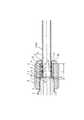
図1は、本発明の第1の実施の形態のアルミニウム管接続前の状態を示す。図2は、接続完了状態を示す。この冷媒用管継手構造は、雄ネジ付き継手本体1と、雄ネジ2に螺着される袋ナット3と、を備え、アルミニウム管4を接続する冷媒用管継手構造であって、アルミニウム管4の端部5にフレア加工を施すことなく、アルミニウム管4と管継手6が接続される。継手本体1及び袋ナット3は、例えば真鍮から成る。アルミニウム管4及び管継手6の内部をエアコン等の冷媒が流れる。 FIG. 1 shows a state before connection of an aluminum pipe according to the first embodiment of the present invention. FIG. 2 shows a connection completion state. This refrigerant pipe joint structure is a refrigerant pipe joint structure that includes a
図3(A)にアルミニウム製圧縮変形用スリーブ7を示す。圧縮変形用スリーブ7は、外周面8に2本のU字状凹周溝9を有する。図1・図2に示すように、圧縮変形用スリーブ7が袋ナット3の内部収納空間10に収納される。 FIG. 3A shows an aluminum
図3(A)(B)に示すように、圧縮変形用スリーブ7の内周面11に予め一体にシール層12を有する。シール層12は、例えば、PTFE等のフッ素樹脂を塗装することにより形成する。圧縮変形用スリーブ7は、袋ナット3(図1・図2参照)と継手本体1の雄ネジ2を螺着させる際に、図3(B)の自由状態から、図3(C)に示すように、継手本体1と袋ナット3からアキシャル方向の圧縮力(締付力)Fを受けて、凹周溝底薄壁部13がラジアル内方向へU字状に塑性変形して、挿入されているアルミニウム管4の外周面14側から食い込んで抜止めする(引抜耐力を有し、引抜けを防止する)。このとき、図2と図3(C)に示すように、アルミニウム管4の内周面もラジアル内方向に塑性変形して小凸条部25を形成する。凹周溝9の幅寸法Wは、塑性変形の際、減少する。なお、幅寸法Wがゼロとなる(すなわち側面15どうしが圧接する)も良い(図示省略)。また、図3(C)のように、食い込みの際にシール層12によって密封状態となる。 As shown in FIGS. 3A and 3B, a
図1と図2に示すように、継手本体1は、端部16にテーパ面17を有する(例えばJIS B8607のフレア管継手に用いられる継手本体と同一形状とする)。図3(A)及び図1・図2に示すように、圧縮変形用スリーブ7は、端部18に、継手本体1のテーパ面17に対応した(同一傾斜角度θの)圧接シール用テーパ面19を有する。テーパ面17と圧接シール用テーパ面19は、従来のフレア管継手の管継手構造と同様に圧接により密封作用をなす。
図3(D)は、変形例を示す要部拡大断面図であって、(上述した)テーパ面17とテーパ面19とが強く圧接した際に、端部18が(ラジアル外方向に)過大な拡径塑性変形を発生することを防止するため、補強用内鍔部28をラジアル内方向に突設させている。なお、この内鍔部28の内方高さに相当する段差寸法Hは、図1,図2の管(パイプ)4(40)の肉厚寸法と略同一とするのが望ましい。
さらに、後述する図10に示した別の実施の形態に於て、補強用内鍔部28を2点鎖線のように突設するも好ましく、また、図7(B)に示した他の実施形態のように、補強用内鍔部28を突設して、その段差寸法Hを、管(パイプ)4(40)の肉厚寸法T4と略同一とする。As shown in FIGS. 1 and 2, the
FIG. 3D is an enlarged cross-sectional view of a main part showing a modification, and when the tapered
Furthermore, in another embodiment shown in FIG. 10 to be described later, it is also preferable to project the reinforcing
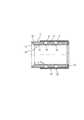
図4に示すように、袋ナット3の少なくとも内面受口20及び外端面26に、電蝕防止のための絶縁性樹脂21を塗装する。袋ナットが真鍮等のアルミニウムとは異なる金属から成っても、異種金属の間での電蝕の発生を防止することができる。樹脂21は、例えば、エポキシ樹脂から成るのが好ましい。 As shown in FIG. 4, an insulating
図5は、本発明の第2の実施の形態のアルミニウム管接続前の状態を示す。図6は、接続完了状態を示す。図5〜図7に示すように、圧縮変形用スリーブ7が内周面11に2本のシール溝22を有する。シール溝22内にOリング等のシール材23が内装される。圧縮変形用スリーブ7の内周面11はシール層を有していない。(圧縮変形用スリーブ7のアキシャル方向長さ寸法Lは、第1の実施の形態より長くなる。)その他の構成は、第1の実施の形態と同様である。
ところで、図7(B)は、図7(A),図5,図6の変形例に相当するものであって、シール材23(シール溝22)の位置と、凹周溝9の位置とを、アキシャル方向に入れ替えた構成である。この図7(B)のように構成すれば、配管接続完了状態下(図6参照)で、凹周溝底薄壁部13が管4(40)の外周面14への圧着による密封作用が第1段階で働き、仮にこの密封作用が不十分な場合に、(ラジアル外方側の)シール材23によって、確実な密封作用をなすことができる。FIG. 5 shows a state before the aluminum pipe connection according to the second embodiment of the present invention. FIG. 6 shows a connection completion state. As shown in FIGS. 5 to 7, the
7B corresponds to the modification of FIG. 7A, FIG. 5 and FIG. 6, and the position of the sealing material 23 (seal groove 22) and the position of the concave
既述の第1・第2の実施の形態に於て、スリーブ7としては、アルミニウム管4と同一材質のアルミニウムを用いることが好ましいが、所望により、外表面に(メッキ加工や溶射等によって)アルミニウム層が被覆された銅をもって構成することもできる。つまり、電蝕を防止することができれば、後者を選択可能である。 In the first and second embodiments already described, it is preferable to use aluminum of the same material as the
次に、他の実施の形態について説明すると、図1〜図3に示した第1の実施の形態に於て、パイプとして銅管40を使用する場合には、スリーブ7の材質を銅とする。スリーブ7の他の形状や構成は、図1〜図3で述べた場合と同様であるので詳細を省略する。
次に、さらに別の実施の形態について説明すると、図5と図6に示した第2の実施の形態に於て、パイプとして銅管40を使用する場合には、スリーブ7の材質を銅とする。スリーブ7の他の形状や構成は、図5と図6で述べた場合と同様であるので詳細を省略する。
なお、いずれの実施の形態の場合も、パイプが銅管40の場合には、図4に示した袋ナット3を銅として、樹脂21の被膜を省略可能な場合がある。Next, another embodiment will be described. In the first embodiment shown in FIGS. 1 to 3, when the
Next, another embodiment will be described. In the second embodiment shown in FIGS. 5 and 6, when the
In any of the embodiments, when the pipe is the
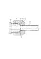
図8は、本発明の第3の実施の形態のアルミニウム管接続前の状態を示す。図9は、接続完了状態を示す。図8〜図10では、圧縮変形用スリーブ7に、ステンレス鋼等の硬質金属(又は硬質プラスチック)製のカバー部材24が外嵌状に取り付けられている。つまり、袋ナット3の内周面3Bと、スリーブ7の外周面との間に、カバー部材24が介在(介装)している。このカバー部材24は、スリーブ7の長さ寸法Lよりも僅かに短いアキシャル方向長さ寸法の円筒部42と、その外端に連設された内鍔部41とから成る。
カバー部材24は、袋ナット3の内周面3Bと、圧縮変形用スリーブ7の外周面との摩擦抵抗(圧着による抵抗)を低減し、滑りを助長するため(即ち、相対的回転滑り助長用)の円筒状のものである。このカバー部材24が無い図2、図6に示した状態下で、スリーブ7が、袋ナット3の螺進(図9矢印M参照)に伴って、アキシャル方向に圧縮変形するときに、スリーブ7の外径寸法も増加する(ラジアル外方への)変形を生じ、袋ナット3の内周面3Bに強く圧着して、スリーブ7が袋ナット3と共廻りし、故に、アルミニウム管4(銅管40)も同時に共廻りして、捩れを発生する虞れがあった。FIG. 8 shows a state before the aluminum pipe connection according to the third embodiment of the present invention. FIG. 9 shows a connection completion state. 8 to 10, a
The
カバー部材24はステンレス鋼等の硬質とし、かつ、好ましくは、摩擦係数も低い材質とすることにより、スリーブ7の外周面と、袋ナット3の内周面が強く圧着して(密着して)起こる上記共廻り、及び、アルミニウム管4(銅管40)の捩れを、防止することができる。なお、袋ナット3と、圧縮変形用スリーブ7の電蝕を防止する機能を発揮する場合もある。さらに言えば、前記内鍔部41は、スリーブ7の外端面と、袋ナット3の内鍔部3Aとの間の摩擦抵抗を低減して、滑り易くする作用もなす。 The
なお、U字状凹周溝9の本数は、2本が最も好ましい。U字状凹周溝9が1本では、凹周溝底薄壁部13が塑性変形する際、アルミニウム管4との間ですべりを生じやすく(ずれやすく)、パイプの軸心方向の同一の位置に食込ませることが難しいこともあり、3本では、各U字状凹周溝9間に不必要なストレス(内部応力)が残る虞れがあるからである。なお、本発明に於て、「アルミニウム」には、アルミニウム合金を含むものとし、また、「銅」には、銅系合金を含むものとする。 The number of U-shaped concave
本発明は、設計変更可能であって、図5,図6の実施形態に、カバー部材24を介装しても自由である(図示省略)。さらに、圧縮変形用スリーブ7が、外周面8に1本又は3本の凹周溝9を有するも良い。また、圧縮変形用スリーブ7が、内周面11に1本のシール溝22を有するも良い。また、袋ナット3の全表面に樹脂21を塗装するも良い。 The design of the present invention can be changed, and the
以上のように、本発明は、雄ネジ付き継手本体1と、継手本体1の雄ネジ2に螺着される袋ナット3と、を備え、アルミニウム管4を接続する冷媒用管継手構造に於て、袋ナット3の内部収納空間10に収納されるとともに、外周面8に凹周溝9を有し、袋ナット3と継手本体1の雄ネジ2を螺着させる際に継手本体1と袋ナット3からアキシャル方向の圧縮力Fを受けて、凹周溝底薄壁部13がラジアル内方向へ塑性変形して、挿入されているアルミニウム管4の外周面14側から食い込んで抜止めする圧縮変形用スリーブ7を有するので、迅速に強力な接続(配管)作業を行い得る。さらに、アルミニウム管4にフレア加工を施す必要がなく、作業効率が良い。また、部品点数が少なく、部品形状がシンプルであって、容易に組立てることができる。
また、上記圧縮変形用スリーブ7は、アルミニウム又はアルミニウム層を被覆した銅からなるので、アルミニウム管4に対して電蝕の心配がなく好ましい。As described above, the present invention provides a refrigerant pipe joint structure that includes the
The
また、雄ネジ付き継手本体1と、継手本体1の雄ネジ2に螺着される袋ナット3と、を備え、銅管40を接続する冷媒用管継手構造に於て、袋ナット3の内部収納空間10に収納されると共に、外周面8に凹周溝9を有し、袋ナット3と継手本体1の雄ネジ2を螺着させる際に継手本体1と袋ナット3からアキシャル方向の圧縮力Fを受けて、凹周溝底薄壁部13がラジアル内方向へ塑性変形して、挿入されている銅管40の外周面14側から食い込んで抜止めする圧縮変形用スリーブ7を有するので、従来の銅管端部へのフレア加工が全く不要となり、迅速な配管作業を行い得て、作業能率の向上を図り得て、かつ、強力な接続完了の構造となる。さらに、部品点数が少なく、部品形状もシンプルとなる。 In addition, in the refrigerant pipe joint structure that includes the
また、圧縮変形用スリーブ7は、銅からなるので、銅管40に対して、電蝕の心配もなくなる。
また、圧縮変形用スリーブ7の内周面11に予め一体にシール層12を有して、食い込みの際に密封状態となるように構成したので、シール性が良好である。
また、圧縮変形用スリーブ7が内周面11にシール溝22を有し、シール溝22内にシール材23を内装したので、シール性をより向上・安定させることができる。なお、パイプ外周面と、袋ナット3の外端面26の隅部Zには雨水等が溜りやすいが、絶縁性樹脂21を被覆すれば、パイプがアルミニウムから成り、かつ、継手本体1及び袋ナット3が真鍮等のアルミニウムとは異なる金属から成っていても、異種金属の間での電蝕の発生を防止することができる。
また、袋ナットの内周面と、圧縮変形用スリーブの外周面との間に、相対的回転滑り助長用円筒状カバー部材を介在させた構成とすることによって、袋ナット3の内周面3Bと、スリーブ7の外周面との間が軽く回転して、最終的にアルミニウム管4又は銅管40が捩れるという問題を解決して、確実に配管接続作業が容易となる。Further, since the
Further, since the
Further, since the
Further, the inner
1 (雄ネジ付き)継手本体
2 雄ネジ
3 袋ナット
4 アルミニウム管
7 圧縮変形用スリーブ
8 外周面
9 凹周溝
10 内部収納空間
11 内周面
12 シール層
13 凹周溝底薄壁部
14 外周面
22 シール溝
23 シール材
24 カバー部材
40 銅管
F 圧縮力(締付力)DESCRIPTION OF SYMBOLS 1 (With external thread) Joint
本発明は、冷媒用管継手構造に関する。 The present invention relates to a pipe joint structure for refrigerant.
管継手の一種として、フレア継手が広く用いられている(例えば、特許文献1参照)。
一般に、図11に示すように、雄ネジ付き継手本体30のテーパ面31と、継手本体30の雄ネジ32に螺着される袋ナット33のテーパ面34の間に、銅製パイプ35の端部を拡径テーパ状に塑性加工して成るフレア端部37を、挟持させて圧接力により密封する構造である。A flare joint is widely used as a kind of pipe joint (see, for example, Patent Document 1).
In general, as shown in FIG. 11, the end portion of the
しかし、近年、パイプ35の材質として、高価で重い銅より、安価で軽いアルミニウムを用いたいという要望が強い。パイプ35がアルミニウムから成る場合、フレア加工を施すのが困難であるという欠点があった。勿論、銅管についても、上記フレア加工を現場で行う必要があるため、配管作業能率アップを阻害しているという欠点があった。また、それらの問題を回避するために種々の管継手構造が提案されているが、部品点数が多く、複雑な形状の部品を必要とし、組立時に手間がかかるという欠点があった。 However, in recent years, there is a strong demand to use cheap and light aluminum as a material for the
解決しようとする課題は、アルミニウム管にフレア加工を施すのが困難だという点である。あるいは、銅管にあっても、フレア加工が配管作業現場の作業能率アップを阻害していた点である。また、それらの問題を回避するための種々の管継手構造では、部品点数が多く、複雑な形状の部品を必要とし、組立時に手間がかかる点である。 The problem to be solved is that it is difficult to flare the aluminum tube. Or even if it exists in a copper pipe, it is the point to which the flare process had inhibited the work efficiency improvement of the piping work site. Moreover, in various pipe joint structures for avoiding these problems, the number of parts is large and parts having complicated shapes are required, which takes time during assembly.
本発明に係る冷媒用管継手構造は、端部にテーパ面を有する雄ネジ付き継手本体と、該継手本体の雄ネジに螺着される袋ナットと、を備え、アルミニウム管を接続する冷媒用管継手構造に於て、上記袋ナットの内部収納空間に収納されると共に、外周面に凹周溝を有する円筒形状の圧縮変形用スリーブを具備し、該圧縮変形用スリーブは、内周面が平滑円周面状に形成され、かつ、端部に上記継手本体の上記テーパ面に対応した圧接シール用テーパ面を有し、上記袋ナットと上記継手本体の雄ネジを螺着させる際に上記継手本体と上記袋ナットからアキシャル方向の圧縮力を受けて、上記凹周溝の幅寸法が減少しつつ凹周溝底薄壁部がラジアル内方向へ突出するように塑性変形して、挿入されている上記アルミニウム管の外周面側から食い込んで抜止めすると共に、上記テーパ面と上記圧接シール用テーパ面が圧接により密封作用をなすように構成されているものである。
また、上記圧縮変形用スリーブは、アルミニウム又はアルミニウム層を被覆した銅から成るものである。A refrigerant pipe joint structure according to the present inventioncomprises a male threaded joint bodyhaving a tapered surface at an end , and a cap nut screwed to the male thread of the joint body, for refrigerant connection to which an aluminum pipe is connected. at a pipe joint structure, while being accommodated inside the housing space of the cap nut,provided with a compressive deformation sleeve of cylindrical shape have a concave peripheral groove on an outer circumferentialsurface, said compressive deformation sleeve is an inner circumferential surface Is formed in a smooth circumferential surface, and has a pressure contact sealing taper surface corresponding to the taper surface of the joint body at the end, and when the cap nut and the male thread of the joint body are screwed together Axial compressive force is received from the joint body and the cap nut, and the concave circumferential groove bottom thin wall portion is plastically deformed and insertedso thatthe width dimension of the concave circumferential groove is reduced and inserted. Biting in from the outer peripheral side of the aluminum tube Inaddition to retainingfit, the tapered surface and the pressure sealing bevel surface is onethat is configured to form a sealing action by pressure contact.
The compression deformation sleeve is made of aluminum or copper coated with an aluminum layer.
また、端部にテーパ面を有する雄ネジ付き継手本体と、該継手本体の雄ネジに螺着される袋ナットと、を備え、銅管を接続する冷媒用管継手構造に於て、上記袋ナットの内部収納空間に収納されると共に、外周面に凹周溝を有する円筒形状の圧縮変形用スリーブを具備し、該圧縮変形用スリーブは、内周面が平滑円周面状に形成され、かつ、端部に上記継手本体の上記テーパ面に対応した圧接シール用テーパ面を有し、上記袋ナットと上記継手本体の雄ネジを螺着させる際に上記継手本体と上記袋ナットからアキシャル方向の圧縮力を受けて、上記凹周溝の幅寸法が減少しつつ凹周溝底薄壁部がラジアル内方向へ突出するように塑性変形して、挿入されている上記銅管の外周面側から食い込んで抜止めすると共に、上記テーパ面と上記圧接シール用テーパ面が圧接により密封作用をなすように構成されているものである。
また、上記圧縮変形用スリーブは、銅から成るものである。
また、上記圧縮変形用スリーブの上記内周面に予め一体にシール層を有して、上記食い込みの際に密封状態となるように構成したものである。
また、上記圧縮変形用スリーブが上記内周面にシール溝を有し、該シール溝内にシール材を内装したものである。
また、上記袋ナットの内周面と、上記圧縮変形用スリーブの外周面との間に、相対的回転滑り助長用円筒状カバー部材を介在させた構成とするも好ましい。In the refrigerant pipe joint structure for connecting a copper pipe, comprisinga male threaded joint bodyhaving a tapered surface at an end , and a cap nut screwed to the male thread of the joint body. while being housed in the housing space of the nut,comprising a compression deformation sleeve of cylindrical shape have a concave peripheral groove on an outer circumferentialsurface, said compressive deformation sleeve has an inner circumferential surface formed on the smooth circumferential surface shape And a taper surface for pressure sealing corresponding to the taper surface of the joint body at the end, and when the cap nut and the male thread of the joint body are screwed together, the joint body and the cap nut are axially The outer circumferential surface of the inserted copper tube is subjected to plastic deformationso thatthe width of the concave circumferential groove is reduced and the bottom wall of the concave circumferential grooveprotrudes radially inwardwhile receiving the compressive force in the direction.while retaining fit bite from theside, the tapered surface and the pressure sheet Le bevel surface is onethat is configured to form a sealing action by pressure contact.
The compression deformation sleeve is made of copper.
Further, a sealing layer in advance integrally withthe inner peripheral surface of the sleeve for the compressive deformation, which is constituted so as to be sealed at the time of the bite.
Also has a seal groove the compression deformation sleeve withinthe inner peripheral surface, it is obtained by interior sealing member into the seal groove.
Moreover, it is also preferable that a cylindrical cover member for assisting relative rotational slippage is interposed between the inner peripheral surface of the cap nut and the outer peripheral surface of the compression deformation sleeve.
本発明の冷媒用管継手構造によれば、塑性加工が難しいアルミニウムパイプの場合、又は、従来のフレア加工を必要としていた銅製パイプの場合、いすれも、端部にフレア加工を施す必要がなく、作業効率が良い。しかも、袋ナットを螺進するだけで、強力な引抜力を発揮し、かつ、密封性も発揮する接続(配管)を迅速・容易に行い得る。また、部品点数が少なく、部品形状がシンプルであって、容易に組立てることができる。 According to the refrigerant pipe joint structure of the present invention, in the case of an aluminum pipe that is difficult to be plastically processed, or in the case of a copper pipe that required a conventional flaring process, there is no need to flare the end part. , Work efficiency is good. Moreover, by simply screwing the cap nut, a connection (pipe) that exhibits a strong pulling force and also exhibits a sealing property can be quickly and easily performed. Further, the number of parts is small, the part shape is simple, and it can be easily assembled.
図1は、本発明の第1の実施の形態のアルミニウム管接続前の状態を示す。図2は、接続完了状態を示す。この冷媒用管継手構造は、雄ネジ付き継手本体1と、雄ネジ2に螺着される袋ナット3と、を備え、アルミニウム管4を接続する冷媒用管継手構造であって、アルミニウム管4の端部5にフレア加工を施すことなく、アルミニウム管4と管継手6が接続される。継手本体1及び袋ナット3は、例えば真鍮から成る。アルミニウム管4及び管継手6の内部をエアコン等の冷媒が流れる。 FIG. 1 shows a state before connection of an aluminum pipe according to the first embodiment of the present invention. FIG. 2 shows a connection completion state. This refrigerant pipe joint structure is a refrigerant pipe joint structure that includes a
図3(A)にアルミニウム製圧縮変形用スリーブ7を示す。圧縮変形用スリーブ7は、外周面8に2本のU字状凹周溝9を有する。図1・図2に示すように、圧縮変形用スリーブ7が袋ナット3の内部収納空間10に収納される。 FIG. 3A shows an aluminum
図3(A)(B)に示すように、圧縮変形用スリーブ7の内周面11に予め一体にシール層12を有する。シール層12は、例えば、PTFE等のフッ素樹脂を塗装することにより形成する。圧縮変形用スリーブ7は、袋ナット3(図1・図2参照)と継手本体1の雄ネジ2を螺着させる際に、図3(B)の自由状態から、図3(C)に示すように、継手本体1と袋ナット3からアキシャル方向の圧縮力(締付力)Fを受けて、凹周溝底薄壁部13がラジアル内方向へU字状に塑性変形して、挿入されているアルミニウム管4の外周面14側から食い込んで抜止めする(引抜耐力を有し、引抜けを防止する)。このとき、図2と図3(C)に示すように、アルミニウム管4の内周面もラジアル内方向に塑性変形して小凸条部25を形成する。凹周溝9の幅寸法Wは、塑性変形の際、減少する。なお、幅寸法Wがゼロとなる(すなわち側面15どうしが圧接する)も良い(図示省略)。また、図3(C)のように、食い込みの際にシール層12によって密封状態となる。 As shown in FIGS. 3A and 3B, a
図1と図2に示すように、継手本体1は、端部16にテーパ面17を有する(例えばJIS B8607のフレア管継手に用いられる継手本体と同一形状とする)。図3(A)及び図1・図2に示すように、圧縮変形用スリーブ7は、端部18に、継手本体1のテーパ面17に対応した(同一傾斜角度θの)圧接シール用テーパ面19を有する。テーパ面17と圧接シール用テーパ面19は、従来のフレア管継手の管継手構造と同様に圧接により密封作用をなす。
図3(D)は、変形例を示す要部拡大断面図であって、(上述した)テーパ面17とテーパ面19とが強く圧接した際に、端部18が(ラジアル外方向に)過大な拡径塑性変形を発生することを防止するため、補強用内鍔部28をラジアル内方向に突設させている。なお、この内鍔部28の内方高さに相当する段差寸法Hは、図1,図2の管(パイプ)4(40)の肉厚寸法と略同一とするのが望ましい。
さらに、後述する図10に示した別の実施の形態に於て、補強用内鍔部28を2点鎖線のように突設するも好ましく、また、図7(B)に示した他の実施形態のように、補強用内鍔部28を突設して、その段差寸法Hを、管(パイプ)4(40)の肉厚寸法T4と略同一とする。As shown in FIGS. 1 and 2, the
FIG. 3D is an enlarged cross-sectional view of a main part showing a modification, and when the tapered
Furthermore, in another embodiment shown in FIG. 10 to be described later, it is also preferable to project the reinforcing
図4に示すように、袋ナット3の少なくとも内面受口20及び外端面26に、電蝕防止のための絶縁性樹脂21を塗装する。袋ナットが真鍮等のアルミニウムとは異なる金属から成っても、異種金属の間での電蝕の発生を防止することができる。樹脂21は、例えば、エポキシ樹脂から成るのが好ましい。 As shown in FIG. 4, an insulating
図5は、本発明の第2の実施の形態のアルミニウム管接続前の状態を示す。図6は、接続完了状態を示す。図5〜図7に示すように、圧縮変形用スリーブ7が内周面11に2本のシール溝22を有する。シール溝22内にOリング等のシール材23が内装される。圧縮変形用スリーブ7の内周面11はシール層を有していない。(圧縮変形用スリーブ7のアキシャル方向長さ寸法Lは、第1の実施の形態より長くなる。)その他の構成は、第1の実施の形態と同様である。
ところで、図7(B)は、図7(A),図5,図6の変形例に相当するものであって、シール材23(シール溝22)の位置と、凹周溝9の位置とを、アキシャル方向に入れ替えた構成である。この図7(B)のように構成すれば、配管接続完了状態下(図6参照)で、凹周溝底薄壁部13が管4(40)の外周面14への圧着による密封作用が第1段階で働き、仮にこの密封作用が不十分な場合に、(ラジアル外方側の)シール材23によって、確実な密封作用をなすことができる。FIG. 5 shows a state before the aluminum pipe connection according to the second embodiment of the present invention. FIG. 6 shows a connection completion state. As shown in FIGS. 5 to 7, the
7B corresponds to the modification of FIG. 7A, FIG. 5 and FIG. 6, and the position of the sealing material 23 (seal groove 22) and the position of the concave
既述の第1・第2の実施の形態に於て、スリーブ7としては、アルミニウム管4と同一材質のアルミニウムを用いることが好ましいが、所望により、外表面に(メッキ加工や溶射等によって)アルミニウム層が被覆された銅をもって構成することもできる。つまり、電蝕を防止することができれば、後者を選択可能である。 In the first and second embodiments already described, it is preferable to use aluminum of the same material as the
次に、他の実施の形態について説明すると、図1〜図3に示した第1の実施の形態に於て、パイプとして銅管40を使用する場合には、スリーブ7の材質を銅とする。スリーブ7の他の形状や構成は、図1〜図3で述べた場合と同様であるので詳細を省略する。
次に、さらに別の実施の形態について説明すると、図5と図6に示した第2の実施の形態に於て、パイプとして銅管40を使用する場合には、スリーブ7の材質を銅とする。スリーブ7の他の形状や構成は、図5と図6で述べた場合と同様であるので詳細を省略する。
なお、いずれの実施の形態の場合も、パイプが銅管40の場合には、図4に示した袋ナット3を銅として、樹脂21の被膜を省略可能な場合がある。Next, another embodiment will be described. In the first embodiment shown in FIGS. 1 to 3, when the
Next, another embodiment will be described. In the second embodiment shown in FIGS. 5 and 6, when the
In any of the embodiments, when the pipe is the
図8は、本発明の第3の実施の形態のアルミニウム管接続前の状態を示す。図9は、接続完了状態を示す。図8〜図10では、圧縮変形用スリーブ7に、ステンレス鋼等の硬質金属(又は硬質プラスチック)製のカバー部材24が外嵌状に取り付けられている。つまり、袋ナット3の内周面3Bと、スリーブ7の外周面との間に、カバー部材24が介在(介装)している。このカバー部材24は、スリーブ7の長さ寸法Lよりも僅かに短いアキシャル方向長さ寸法の円筒部42と、その外端に連設された内鍔部41とから成る。
カバー部材24は、袋ナット3の内周面3Bと、圧縮変形用スリーブ7の外周面との摩擦抵抗(圧着による抵抗)を低減し、滑りを助長するため(即ち、相対的回転滑り助長用)の円筒状のものである。このカバー部材24が無い図2、図6に示した状態下で、スリーブ7が、袋ナット3の螺進(図9矢印M参照)に伴って、アキシャル方向に圧縮変形するときに、スリーブ7の外径寸法も増加する(ラジアル外方への)変形を生じ、袋ナット3の内周面3Bに強く圧着して、スリーブ7が袋ナット3と共廻りし、故に、アルミニウム管4(銅管40)も同時に共廻りして、捩れを発生する虞れがあった。FIG. 8 shows a state before the aluminum pipe connection according to the third embodiment of the present invention. FIG. 9 shows a connection completion state. 8 to 10, a
The
カバー部材24はステンレス鋼等の硬質とし、かつ、好ましくは、摩擦係数も低い材質とすることにより、スリーブ7の外周面と、袋ナット3の内周面が強く圧着して(密着して)起こる上記共廻り、及び、アルミニウム管4(銅管40)の捩れを、防止することができる。なお、袋ナット3と、圧縮変形用スリーブ7の電蝕を防止する機能を発揮する場合もある。さらに言えば、前記内鍔部41は、スリーブ7の外端面と、袋ナット3の内鍔部3Aとの間の摩擦抵抗を低減して、滑り易くする作用もなす。 The
なお、U字状凹周溝9の本数は、2本が最も好ましい。U字状凹周溝9が1本では、凹周溝底薄壁部13が塑性変形する際、アルミニウム管4との間ですべりを生じやすく(ずれやすく)、パイプの軸心方向の同一の位置に食込ませることが難しいこともあり、3本では、各U字状凹周溝9間に不必要なストレス(内部応力)が残る虞れがあるからである。なお、本発明に於て、「アルミニウム」には、アルミニウム合金を含むものとし、また、「銅」には、銅系合金を含むものとする。 The number of U-shaped concave
本発明は、設計変更可能であって、図5,図6の実施形態に、カバー部材24を介装しても自由である(図示省略)。さらに、圧縮変形用スリーブ7が、外周面8に1本又は3本の凹周溝9を有するも良い。また、圧縮変形用スリーブ7が、内周面11に1本のシール溝22を有するも良い。また、袋ナット3の全表面に樹脂21を塗装するも良い。 The design of the present invention can be changed, and the
以上のように、本発明は、雄ネジ付き継手本体1と、継手本体1の雄ネジ2に螺着される袋ナット3と、を備え、アルミニウム管4を接続する冷媒用管継手構造に於て、袋ナット3の内部収納空間10に収納されるとともに、外周面8に凹周溝9を有し、袋ナット3と継手本体1の雄ネジ2を螺着させる際に継手本体1と袋ナット3からアキシャル方向の圧縮力Fを受けて、凹周溝底薄壁部13がラジアル内方向へ塑性変形して、挿入されているアルミニウム管4の外周面14側から食い込んで抜止めする圧縮変形用スリーブ7を有するので、迅速に強力な接続(配管)作業を行い得る。さらに、アルミニウム管4にフレア加工を施す必要がなく、作業効率が良い。また、部品点数が少なく、部品形状がシンプルであって、容易に組立てることができる。
また、上記圧縮変形用スリーブ7は、アルミニウム又はアルミニウム層を被覆した銅からなるので、アルミニウム管4に対して電蝕の心配がなく好ましい。As described above, the present invention provides a refrigerant pipe joint structure that includes the
The
また、雄ネジ付き継手本体1と、継手本体1の雄ネジ2に螺着される袋ナット3と、を備え、銅管40を接続する冷媒用管継手構造に於て、袋ナット3の内部収納空間10に収納されると共に、外周面8に凹周溝9を有し、袋ナット3と継手本体1の雄ネジ2を螺着させる際に継手本体1と袋ナット3からアキシャル方向の圧縮力Fを受けて、凹周溝底薄壁部13がラジアル内方向へ塑性変形して、挿入されている銅管40の外周面14側から食い込んで抜止めする圧縮変形用スリーブ7を有するので、従来の銅管端部へのフレア加工が全く不要となり、迅速な配管作業を行い得て、作業能率の向上を図り得て、かつ、強力な接続完了の構造となる。さらに、部品点数が少なく、部品形状もシンプルとなる。 In addition, in the refrigerant pipe joint structure that includes the
また、圧縮変形用スリーブ7は、銅からなるので、銅管40に対して、電蝕の心配もなくなる。
また、圧縮変形用スリーブ7の内周面11に予め一体にシール層12を有して、食い込みの際に密封状態となるように構成したので、シール性が良好である。
また、圧縮変形用スリーブ7が内周面11にシール溝22を有し、シール溝22内にシール材23を内装したので、シール性をより向上・安定させることができる。なお、パイプ外周面と、袋ナット3の外端面26の隅部Zには雨水等が溜りやすいが、絶縁性樹脂21を被覆すれば、パイプがアルミニウムから成り、かつ、継手本体1及び袋ナット3が真鍮等のアルミニウムとは異なる金属から成っていても、異種金属の間での電蝕の発生を防止することができる。
また、袋ナットの内周面と、圧縮変形用スリーブの外周面との間に、相対的回転滑り助長用円筒状カバー部材を介在させた構成とすることによって、袋ナット3の内周面3Bと、スリーブ7の外周面との間が軽く回転して、最終的にアルミニウム管4又は銅管40が捩れるという問題を解決して、確実に配管接続作業が容易となる。Further, since the
Further, since the
Further, since the
Further, the inner
1 (雄ネジ付き)継手本体
2 雄ネジ
3 袋ナット
4 アルミニウム管
7 圧縮変形用スリーブ
8 外周面
9 凹周溝
10 内部収納空間
11 内周面
12 シール層
13 凹周溝底薄壁部
14 外周面
16端部
17テーパ面
18端部
19圧接シール用テーパ面
22 シール溝
23 シール材
24 カバー部材
40 銅管
F 圧縮力(締付力)
W幅寸法
DESCRIPTION OF SYMBOLS 1 (With external thread) Joint
16ends
17taper surface
18ends
19Taper surface for
Wwidth dimension
Claims (7)
Translated fromJapanese上記袋ナット(3)の内部収納空間(10)に収納されると共に、外周面(8)に凹周溝(9)を有し、上記袋ナット(3)と上記継手本体(1)の雄ネジ(2)を螺着させる際に上記継手本体(1)と上記袋ナット(3)からアキシャル方向の圧縮力(F)を受けて、凹周溝底薄壁部(13)がラジアル内方向へ塑性変形して、挿入されている上記アルミニウム管(4)の外周面(14)側から食い込んで抜止めする圧縮変形用スリーブ(7)を有することを特徴とする冷媒用管継手構造。A pipe joint structure for refrigerant comprising a joint body (1) with a male thread and a cap nut (3) screwed onto the male thread (2) of the joint body (1) and connecting an aluminum pipe (4) In
The cap nut is housed in the internal storage space (10) of the nut (3), has a concave groove (9) on the outer peripheral surface (8), and is a male of the cap nut (3) and the joint body (1). When the screw (2) is screwed, the axially compressive force (F) is received from the joint body (1) and the cap nut (3), so that the concave groove bottom thin wall portion (13) is radially inward. A refrigerant pipe joint structure characterized by having a compression deformation sleeve (7) which is plastically deformed and bites in from the outer peripheral surface (14) side of the inserted aluminum pipe (4) to prevent it from being removed.
上記袋ナット(3)の内部収納空間(10)に収納されると共に、外周面(8)に凹周溝(9)を有し、上記袋ナット(3)と上記継手本体(1)の雄ネジ(2)を螺着させる際に上記継手本体(1)と上記袋ナット(3)からアキシャル方向の圧縮力(F)を受けて、凹周溝底薄壁部(13)がラジアル内方向へ塑性変形して、挿入されている上記銅管(40)の外周面(14)側から食い込んで抜止めする圧縮変形用スリーブ(7)を有することを特徴とする冷媒用管継手構造。A pipe joint structure for refrigerant comprising a joint body (1) with a male thread and a cap nut (3) screwed onto the male thread (2) of the joint body (1) and connecting a copper pipe (40) In
The cap nut is housed in the internal storage space (10) of the nut (3), has a concave groove (9) on the outer peripheral surface (8), and is a male of the cap nut (3) and the joint body (1). When the screw (2) is screwed, the axially compressive force (F) is received from the joint body (1) and the cap nut (3), so that the concave groove bottom thin wall portion (13) is radially inward. A refrigerant pipe joint structure comprising a compression deformation sleeve (7) which is plastically deformed and bites in from the outer peripheral surface (14) side of the inserted copper pipe (40) to prevent it from being removed.
A cylindrical cover member (24) for promoting relative rotational slip is interposed between an inner peripheral surface (3B) of the cap nut (3) and an outer peripheral surface of the compression deformation sleeve (7). The refrigerant pipe joint structure according to 1, 2, 3, 4, 5 or 6.
Priority Applications (8)
| Application Number | Priority Date | Filing Date | Title |
|---|---|---|---|
| JP2012262696AJP5276215B1 (en) | 2012-09-19 | 2012-11-30 | Pipe joint structure for refrigerant |
| SG11201408371XASG11201408371XA (en) | 2012-09-19 | 2013-05-13 | Pipe joint construction |
| EP13839851.6AEP2899441B1 (en) | 2012-09-19 | 2013-05-13 | Pipe joint structure |
| CN201380048765.6ACN104620034B (en) | 2012-09-19 | 2013-05-13 | Pipe joint constructs |
| US14/411,254US20150137517A1 (en) | 2012-09-19 | 2013-05-13 | Pipe joint construction |
| PCT/JP2013/063279WO2014045632A1 (en) | 2012-09-19 | 2013-05-13 | Pipe joint structure |
| KR1020147036644AKR20150054717A (en) | 2012-09-19 | 2013-05-13 | Pipe joint structure |
| TW102138814ATWI509177B (en) | 2012-11-07 | 2013-10-25 | Pipe joint construction |
Applications Claiming Priority (5)
| Application Number | Priority Date | Filing Date | Title |
|---|---|---|---|
| JP2012205647 | 2012-09-19 | ||
| JP2012205647 | 2012-09-19 | ||
| JP2012245025 | 2012-11-07 | ||
| JP2012245025 | 2012-11-07 | ||
| JP2012262696AJP5276215B1 (en) | 2012-09-19 | 2012-11-30 | Pipe joint structure for refrigerant |
Related Child Applications (1)
| Application Number | Title | Priority Date | Filing Date |
|---|---|---|---|
| JP2013042203ADivisionJP5306553B1 (en) | 2012-09-19 | 2013-03-04 | Pipe joint structure |
Publications (2)
| Publication Number | Publication Date |
|---|---|
| JP5276215B1 JP5276215B1 (en) | 2013-08-28 |
| JP2014111949Atrue JP2014111949A (en) | 2014-06-19 |
Family
ID=49179264
Family Applications (2)
| Application Number | Title | Priority Date | Filing Date |
|---|---|---|---|
| JP2012262696AExpired - Fee RelatedJP5276215B1 (en) | 2012-09-19 | 2012-11-30 | Pipe joint structure for refrigerant |
| JP2013042203AExpired - Fee RelatedJP5306553B1 (en) | 2012-09-19 | 2013-03-04 | Pipe joint structure |
Family Applications After (1)
| Application Number | Title | Priority Date | Filing Date |
|---|---|---|---|
| JP2013042203AExpired - Fee RelatedJP5306553B1 (en) | 2012-09-19 | 2013-03-04 | Pipe joint structure |
Country Status (7)
| Country | Link |
|---|---|
| US (1) | US20150137517A1 (en) |
| EP (1) | EP2899441B1 (en) |
| JP (2) | JP5276215B1 (en) |
| KR (1) | KR20150054717A (en) |
| CN (1) | CN104620034B (en) |
| SG (1) | SG11201408371XA (en) |
| WO (1) | WO2014045632A1 (en) |
Cited By (1)
| Publication number | Priority date | Publication date | Assignee | Title |
|---|---|---|---|---|
| JP2014109296A (en)* | 2012-11-30 | 2014-06-12 | Inoue Sudare Kk | Pipe joint structure |
Families Citing this family (18)
| Publication number | Priority date | Publication date | Assignee | Title |
|---|---|---|---|---|
| KR101295523B1 (en)* | 2012-11-08 | 2013-08-12 | 주식회사 비엠티 | A back ferrule with a bellows shaped elastic portion, and a pipe connecting device having the same |
| JP5503797B1 (en)* | 2013-11-14 | 2014-05-28 | 井上スダレ株式会社 | Pipe joint structure for refrigerant |
| JP5592573B1 (en)* | 2014-01-06 | 2014-09-17 | 井上スダレ株式会社 | Pipe joint structure for refrigerant |
| JP5723470B1 (en)* | 2014-07-15 | 2015-05-27 | 井上スダレ株式会社 | Pipe joint structure for refrigerant |
| JP5736499B1 (en)* | 2014-10-30 | 2015-06-17 | 井上スダレ株式会社 | Pipe joint structure |
| US10094494B2 (en)* | 2015-06-26 | 2018-10-09 | Agilent Technologies, Inc. | Ferrule with features for softening ferrule crush and related methods |
| CN105299346A (en)* | 2015-11-27 | 2016-02-03 | 江苏省绿岛管阀件有限公司 | PP pipe with sealing pipe joint |
| CN105257925A (en)* | 2015-11-27 | 2016-01-20 | 江苏省绿岛管阀件有限公司 | Seal pipe joint for PP pipes |
| JP6276321B2 (en)* | 2016-04-28 | 2018-02-07 | 井上スダレ株式会社 | Pipe joint structure |
| JP2017223277A (en)* | 2016-06-15 | 2017-12-21 | 井上スダレ株式会社 | Pipe joint structure |
| CN107626008A (en)* | 2017-10-31 | 2018-01-26 | 深圳核心医疗器械有限公司 | The outlet connecting mechanism and its assemble method of a kind of artificial blood pump |
| CN108593447A (en)* | 2018-04-20 | 2018-09-28 | 中国石油集团渤海石油装备制造有限公司 | Internal lining pipe water test unit and test method |
| JP6777177B2 (en) | 2019-02-15 | 2020-10-28 | ダイキン工業株式会社 | Units for joint members and air conditioners |
| JP7637531B2 (en)* | 2021-02-26 | 2025-02-28 | 株式会社Pillar | Pipe Fittings |
| CN115750940A (en)* | 2022-11-30 | 2023-03-07 | 叁九科技(杭州)有限公司 | Pipeline connecting device |
| KR102530653B1 (en)* | 2023-02-27 | 2023-05-09 | 주식회사 우정메카트로닉스 | Valve link assembly |
| JP7648929B2 (en) | 2023-03-29 | 2025-03-19 | ダイキン工業株式会社 | Pipe joint cover |
| CN117738592B (en)* | 2024-02-21 | 2024-04-16 | 胜利油田胜机石油装备有限公司 | Electroplating anti-corrosion oil pipe with sealing structure |
Family Cites Families (46)
| Publication number | Priority date | Publication date | Assignee | Title |
|---|---|---|---|---|
| US2287889A (en)* | 1940-12-03 | 1942-06-30 | Mueller Co | Lock joint coupling |
| US2466057A (en)* | 1947-02-18 | 1949-04-05 | Somma Raymond | Combined tube connector and tube flarer |
| US2693374A (en)* | 1950-05-05 | 1954-11-02 | Paul D Wurzburger | Pipe coupling with deformable ring for flareless pipe |
| US2693375A (en)* | 1953-01-23 | 1954-11-02 | Paul D Wurzburger | Double-biting ring pipe coupling |
| US2823935A (en)* | 1953-01-23 | 1958-02-18 | Paul D Wurzburger | Pipe coupling with deformable ring for flareless pipe |
| US3120969A (en)* | 1959-05-12 | 1964-02-11 | Parker Hannifin Corp | Flareless tube coupling |
| US3055684A (en)* | 1959-09-01 | 1962-09-25 | Parker Hannifin Corp | Flareless tube coupling |
| US3174778A (en)* | 1962-05-17 | 1965-03-23 | Curtis Mfg Co | Fitting for tubes |
| US3325192A (en)* | 1964-11-19 | 1967-06-13 | Parker Hannifin Corp | Flareless tube coupling nut and ferrule assembly |
| JPS5441124B2 (en)* | 1974-02-01 | 1979-12-06 | ||
| US3879070A (en)* | 1974-04-22 | 1975-04-22 | Carrier Corp | Tube coupling mechanism |
| GB2071799A (en)* | 1980-03-11 | 1981-09-23 | Hepworth Plastics Ltd | Pipe couplings |
| JPS59114718U (en)* | 1983-01-24 | 1984-08-02 | 船舶商事株式会社 | Packaging for holding wires for marine wire-penetrating hardware |
| US4556242A (en)* | 1983-11-25 | 1985-12-03 | Imperial Clevite Inc. | Vibration resistant high pressure tube fitting |
| US4867489A (en)* | 1987-09-21 | 1989-09-19 | Parker Hannifin Corporation | Tube fitting |
| JPH01180088U (en)* | 1988-06-10 | 1989-12-25 | ||
| JPH0243586U (en)* | 1988-09-19 | 1990-03-26 | ||
| US4940263A (en)* | 1988-10-11 | 1990-07-10 | Dormont Manufacturing Company | Fitting for tubing |
| WO1991008414A1 (en)* | 1989-11-23 | 1991-06-13 | Vulcan Australia Limited | Conduit coupling |
| US5217261A (en)* | 1990-04-23 | 1993-06-08 | Aeroquip Corporation | Flareless compression fitting |
| JPH0728462Y2 (en)* | 1992-03-04 | 1995-06-28 | 株式会社日立物流 | Pipe fitting device |
| DE4229502C2 (en)* | 1992-09-04 | 1998-01-22 | Froehlich Manfred | Cutting ring for a pipe connection |
| JPH07248081A (en)* | 1994-03-10 | 1995-09-26 | Fujii Gokin Seisakusho:Kk | Pipe connection device |
| JPH07248082A (en)* | 1994-03-10 | 1995-09-26 | Fujii Gokin Seisakusho:Kk | Pipe connection method and pipe connection device for implementing the same |
| JPH08135862A (en)* | 1994-11-04 | 1996-05-31 | Fujii Gokin Seisakusho Co Ltd | Pipe joining device and extensible/contractible pipe coupling |
| JP3030497B2 (en)* | 1996-11-05 | 2000-04-10 | 株式会社藤井合金製作所 | Pipe connection device |
| JP3041477B2 (en)* | 1996-11-05 | 2000-05-15 | 株式会社藤井合金製作所 | Pipe connection device |
| DE19709464C2 (en)* | 1997-03-07 | 2000-03-09 | Voss Armaturen | Pipe fitting with cutting ring for metallic pipes |
| JPH11141760A (en)* | 1997-11-10 | 1999-05-28 | Toyo Fitting Kk | Connecting structure for metal pipe and joint |
| JPH11182767A (en)* | 1997-12-24 | 1999-07-06 | Calsonic Corp | Connecting structure of flexible tube |
| KR100258025B1 (en)* | 1998-02-03 | 2000-06-01 | 박실조 | Pipe connecter |
| JP3592079B2 (en)* | 1998-05-21 | 2004-11-24 | 日本フレックス株式会社 | Seal connector |
| JP2000193157A (en)* | 1998-12-25 | 2000-07-14 | Sankei Seisakusho:Kk | Pipe fitting |
| US6575501B1 (en)* | 1999-03-05 | 2003-06-10 | Valco Instruments Company, Inc. | Tube sealing bushing |
| JP2002327876A (en)* | 2001-03-01 | 2002-11-15 | Kitz Corp | Joining structure for coupling and valve and thin pipe coupling |
| JP2002340250A (en)* | 2001-05-21 | 2002-11-27 | Hitachi Metals Ltd | Mechanical pipe joint for metallic pipe |
| JP4239739B2 (en) | 2003-07-24 | 2009-03-18 | 三菱電機株式会社 | Flare piping joint structure and products using the same |
| DE102004026789B4 (en)* | 2004-06-02 | 2008-11-06 | Eaton Fluid Power Gmbh | connecting device |
| CN101379335A (en)* | 2006-01-31 | 2009-03-04 | 大金工业株式会社 | Bite type tube connection structure, tube fitting, valve, closing valve, refrigerating cycle device, hot-water supply device, bite type tube connection method, and on-site tube connection method |
| WO2008028104A2 (en)* | 2006-08-31 | 2008-03-06 | Titeflex Corporation | Crimp fitting for corrugated stainless steel tubing |
| JP4476263B2 (en)* | 2006-09-14 | 2010-06-09 | 智史 井上 | Pipe fitting |
| JP5164668B2 (en)* | 2008-05-22 | 2013-03-21 | アロン化成株式会社 | Pipe joint structure, pipe fittings equipped with this |
| DE102009011411B4 (en)* | 2009-03-03 | 2014-09-18 | Neoperl Gmbh | Sanitary hose coupling |
| US8955886B2 (en)* | 2010-12-08 | 2015-02-17 | Yokohama Industries Americas Inc. | Hydraulic ducts and connecting assemblies |
| CN202349430U (en)* | 2011-11-05 | 2012-07-25 | 钟声远 | Snap-ring type pipe connector |
| GB2505946B (en)* | 2012-09-17 | 2020-07-08 | Parker Hannifin Mfg Uk Limited | A compressible coupling |
- 2012
- 2012-11-30JPJP2012262696Apatent/JP5276215B1/ennot_activeExpired - Fee Related
- 2013
- 2013-03-04JPJP2013042203Apatent/JP5306553B1/ennot_activeExpired - Fee Related
- 2013-05-13CNCN201380048765.6Apatent/CN104620034B/enactiveActive
- 2013-05-13KRKR1020147036644Apatent/KR20150054717A/ennot_activeCeased
- 2013-05-13EPEP13839851.6Apatent/EP2899441B1/enactiveActive
- 2013-05-13WOPCT/JP2013/063279patent/WO2014045632A1/enactiveApplication Filing
- 2013-05-13USUS14/411,254patent/US20150137517A1/ennot_activeAbandoned
- 2013-05-13SGSG11201408371XApatent/SG11201408371XA/enunknown
Cited By (1)
| Publication number | Priority date | Publication date | Assignee | Title |
|---|---|---|---|---|
| JP2014109296A (en)* | 2012-11-30 | 2014-06-12 | Inoue Sudare Kk | Pipe joint structure |
Also Published As
| Publication number | Publication date |
|---|---|
| CN104620034B (en) | 2016-11-09 |
| JP5276215B1 (en) | 2013-08-28 |
| JP5306553B1 (en) | 2013-10-02 |
| EP2899441A1 (en) | 2015-07-29 |
| KR20150054717A (en) | 2015-05-20 |
| EP2899441A4 (en) | 2016-05-25 |
| CN104620034A (en) | 2015-05-13 |
| EP2899441B1 (en) | 2019-08-14 |
| SG11201408371XA (en) | 2015-01-29 |
| JP2014111975A (en) | 2014-06-19 |
| US20150137517A1 (en) | 2015-05-21 |
| WO2014045632A1 (en) | 2014-03-27 |
Similar Documents
| Publication | Publication Date | Title |
|---|---|---|
| JP5276215B1 (en) | Pipe joint structure for refrigerant | |
| JP5592573B1 (en) | Pipe joint structure for refrigerant | |
| US3423109A (en) | Hose fitting | |
| JP2012163132A (en) | Tube joint | |
| JP2007231985A (en) | Piping flange joint | |
| JP2009168075A (en) | Pipe joint structure and pipe connection method | |
| JP6112842B2 (en) | Pipe joint structure | |
| KR101055938B1 (en) | Connecting device of aluminum coated pipe with expansion pipe at its end and connecting method using the same | |
| JP2014109295A (en) | Pipe joint structure | |
| JP5723470B1 (en) | Pipe joint structure for refrigerant | |
| JP5523612B1 (en) | Pipe joint structure | |
| JP5736499B1 (en) | Pipe joint structure | |
| WO2018011906A1 (en) | Pipe joint | |
| JP5934667B2 (en) | Pipe fitting | |
| US20070013189A1 (en) | Sealing fitting for stainless steel tubing | |
| JP5503797B1 (en) | Pipe joint structure for refrigerant | |
| JP2015135170A (en) | Pipe joint structure for refrigerant | |
| JP6234785B2 (en) | Fitting | |
| JP2008309295A (en) | Flare fitting | |
| TWI509177B (en) | Pipe joint construction | |
| JP6448229B2 (en) | Fitting | |
| JP5525897B2 (en) | Pipe fitting | |
| JP2007321857A (en) | Pipe joint | |
| JP6330308B2 (en) | Hose fitting installation method | |
| CN116265796A (en) | Joint for nonmetallic oil pipe, oil pipe and installation method of joint |
Legal Events
| Date | Code | Title | Description |
|---|---|---|---|
| TRDD | Decision of grant or rejection written | ||
| A61 | First payment of annual fees (during grant procedure) | Free format text:JAPANESE INTERMEDIATE CODE: A61 Effective date:20130516 | |
| R150 | Certificate of patent or registration of utility model | Free format text:JAPANESE INTERMEDIATE CODE: R150 | |
| LAPS | Cancellation because of no payment of annual fees |