JP2014110475A - Radio communication device and program therefor - Google Patents
Radio communication device and program thereforDownload PDFInfo
- Publication number
- JP2014110475A JP2014110475AJP2012262922AJP2012262922AJP2014110475AJP 2014110475 AJP2014110475 AJP 2014110475AJP 2012262922 AJP2012262922 AJP 2012262922AJP 2012262922 AJP2012262922 AJP 2012262922AJP 2014110475 AJP2014110475 AJP 2014110475A
- Authority
- JP
- Japan
- Prior art keywords
- wireless communication
- communication terminal
- coaxial cable
- leaky coaxial
- radio wave
- Prior art date
- Legal status (The legal status is an assumption and is not a legal conclusion. Google has not performed a legal analysis and makes no representation as to the accuracy of the status listed.)
- Pending
Links
Images


Landscapes
- Transceivers (AREA)
- Near-Field Transmission Systems (AREA)
- Mobile Radio Communication Systems (AREA)
Abstract
Translated fromJapaneseDescription
Translated fromJapanese本発明の実施形態は、漏洩同軸ケーブルをアンテナとして用いる無線通信装置およびそのプログラムに関する。 Embodiments described herein relate generally to a wireless communication apparatus using a leaky coaxial cable as an antenna and a program thereof.
漏洩同軸ケーブルをアンテナとして用いることにより、その漏洩同軸ケーブルの周りに無線LANエリアいわゆるフリースポットを形成することができる。 By using the leaky coaxial cable as an antenna, a wireless LAN area so-called free spot can be formed around the leaky coaxial cable.
漏洩同軸ケーブルの周りに形成されるフリースポットの大きさつまり通信可能範囲は、漏洩同軸ケーブルの特性に依るところが大きい。したがって、同じ漏洩同軸ケーブルを持つ製品であれば、ほぼ同じ通信可能範囲となる。 The size of the free spot formed around the leaky coaxial cable, that is, the communicable range largely depends on the characteristics of the leaky coaxial cable. Therefore, if the products have the same leaky coaxial cable, the communication range is almost the same.
この通信可能範囲については、設置場所や利用形態などに応じて、適宜に調整できれば便利である。 About this communicable range, it is convenient if it can be adjusted appropriately according to the installation location, usage pattern, and the like.
実施形態の目的は、通信可能範囲を調整できる無線通信装置およびそのプログラムを提供することである。 The objective of embodiment is providing the radio | wireless communication apparatus which can adjust a communicable range, and its program.
実施形態の無線通信装置は、電波の送出および取込みを行う漏洩同軸ケーブルと、この漏洩同軸ケーブルから送出する電波の送信出力を通信対象となる無線通信端末ごとに制御する制御手段と、を備える。 The wireless communication apparatus according to the embodiment includes a leaky coaxial cable that transmits and captures radio waves, and a control unit that controls the transmission output of the radio waves transmitted from the leaky coaxial cable for each wireless communication terminal to be communicated.
以下、一実施形態について図面を参照して説明する。
図1に示すように、床、天井、テーブル等の取付け面1に円盤形の基台2を設置し、その基台2上に円筒形の筐体3を介してタワー型のアンテナ10を直立状態に立設する。アンテナ10は、電波の送出および取込みを行う線状の漏洩同軸ケーブル11、この漏洩同軸ケーブル11から送出される電波(=漏洩同軸ケーブル11に供給される高周波電力)を減衰させる減衰器(アッテネータともいう)12、これら漏洩同軸ケーブル11および減衰器12を被う円筒状のカバー13からなる。Hereinafter, an embodiment will be described with reference to the drawings.
As shown in FIG. 1, a disk-
漏洩同軸ケーブル11は、LCXケーブルとも称し、電波を送出(漏洩)および取込むための多数のスロットを軸方向に配列して有する。この漏洩同軸ケーブル11を含むアンテナ10の周りに、2点鎖線で示す無線LANエリアいわゆるフリースポット(サービスエリアともいう)が形成される。 The leaky
このフリースポットエリアは、通信対象となる無線通信端末A1,A2,B1,B2,C1,C2…との間で実際にデータを送信し得る領域のことで、漏洩同軸ケーブル11から水平方向、漏洩同軸ケーブル11の上端から上方向、漏洩同軸ケーブル11の上端から下方向にそれぞれ距離Dを持つ。そして、このフリースポットエリアの大きさは、漏洩同軸ケーブル11から送出する電波の送信出力(電波の強度)を変えることにより、調節することができる。 This free spot area is an area where data can be actually transmitted with the wireless communication terminals A1, A2, B1, B2, C1, C2,. The distance D is from the upper end of the
減衰器12については、漏洩同軸ケーブル11から送出する電波の送信出力を弱めたい場合に取付けたり、弱めたくない場合は取外しも可能である。減衰量の異なる複数の減衰器12を用意しておき、これら減衰器12のいずれかを選択的に取付ける構成としてもよい。 The attenuator 12 can be attached when the transmission output of the radio wave transmitted from the leaky
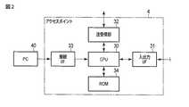
上記筐体3は、アンテナ10を支持することに加え、データの送受信を行う送受信ユニットいわゆるアクセスポイント4を収容する。アクセスポイント4は、図2に示すように、主制御部として機能するCPU30、外部の通信ネットワークに接続される入出力インターフェース31、電波の送受信を行う送受信部32、外部機器接続用の接続インターフェース33、およびROM(リード・オンリ・メモリ)34などを構成要素とするコンピュータを含み、CPU30の内部メモリに記憶されているプログラムにより動作する。 In addition to supporting the
送受信部32は、CPU30からの指示に応じた信号やデータを高周波電力に重畳して漏洩同軸ケーブル11に送るとともに、漏洩同軸ケーブル11で取込まれる電波に含まれる信号やデータを抽出してCPU30に供給する。接続インターフェース33は、外部機器たとえばパーソナルコンピュータ40の接続用として用意されている。ROM34は、予め定められた設定値選定条件を記憶している。 The transmission /
そして、CPU30は、主要な機能として次の(1)の手段を有する。
(1)漏洩同軸ケーブル11から送出する電波の送信出力を通信対象となる無線通信端末ごとに制御する制御手段。具体的には、通信対象となる無線通信端末へのデータ送信に際し、漏洩同軸ケーブル11から送出する電波の送信出力をその無線通信端末に対応する値となるよう制御する。The
(1) Control means for controlling the transmission output of radio waves transmitted from the leaky
なお、この制御手段は、もっと具体的には、漏洩同軸ケーブル11から送出される電波の到達領域に存在する無線通信端末を通信対象として識別する手段と、この識別した無線通信端末に対応する送信出力の設定値を選定する手段と、上記識別した無線通信端末へのデータ送信に際し、漏洩同軸ケーブル11から送出する電波の送信出力を上記選定した設定値となるよう制御する手段と、を含む。 More specifically, the control means includes a means for identifying a wireless communication terminal existing in a reach area of a radio wave transmitted from the leaky
上記識別する手段は、ビーコンが含まれる電波を漏洩同軸ケーブル11から定期的に送出し、漏洩同軸ケーブル11で取込まれる電波のうち、上記定期的な送出に応答して無線通信端末から送出される電波に含まれるビーコンに基づき、その無線通信端末を識別する。この識別により、電波の到達領域に複数の無線通信端末A1,A2,B1,B2,C1,C2…が存在していても、その無線通信端末A1,A2,B1,B2,C1,C2…を個々に認識することができる。 The identifying means periodically transmits a radio wave including a beacon from the leaky
つぎに、アクセスポイント4のCPU30が実行する制御を図3のフローチャートを参照しながら説明する。
CPU30は、当該アクセスポイント4に固有のビーコンを高周波電力に重畳し、その高周波電力に基づく電波を漏洩同軸ケーブル11から定期的(制御ループ毎)に送出する(ステップ101)。このときの電波の送信出力は、例えば100(%)またはそれに近い値であり、障害物等がなければ約50mほど離れたところまで到達する。Next, control executed by the
The
この電波を受けた無線通信端末A1,A2,B1,B2,C1,C2…は、受けた電波に含まれるビーコンに応答して、当該無線通信端末に固有のビーコンを含む電波を送出する。 In response to the beacon included in the received radio wave, the radio communication terminals A1, A2, B1, B2, C1, C2... Receiving the radio wave transmit a radio wave including a beacon unique to the radio communication terminal.
CPU30は、漏洩同軸ケーブル11で受けた電波にビーコンが含まれていれば(ステップ102のYES)、そのビーコンに含まれる識別データに基づいて送信元の無線通信端末A1,A2,B1,B2,C1,C2…をそれぞれ識別する(ステップ103)。 If a beacon is included in the radio wave received by leaky coaxial cable 11 (YES in step 102),
そして、CPU30は、識別した無線通信端末A1,A2,B1,B2,C1,C2…に対応する送信出力の設定値(%)を、ROM34内の図4に示す設定値選定条件の参照により、選定する(ステップ104)。設定値選定条件は、無線通信端末A1,A2,B1,B2,C1,C2…の種類・機能・送信出力・所有者などを考慮しながらその無線通信端末のそれぞれに対して設定値を割当てたもので、無線通信端末A1,A2については設定値25(%)、無線通信端末B1,B2については設定値50(%)、無線通信端末C1,C2については設定値100(%)を定めている。 Then, the
CPU30は、識別した無線通信端末へのデータ送信に際し、漏洩同軸ケーブル11から送出する電波の送信出力を上記選定した設定値となるよう制御する(ステップ105)。 When transmitting data to the identified wireless communication terminal, the
すなわち、無線通信端末A1へのデータ送信に際しては、送信出力を25(%)に設定する。この場合、送信出力が小さいので、通信可能範囲つまりデータ送信の範囲が図1に2点鎖線で示す3つの領域のうち最も内側の領域に制限される。この領域に無線通信端末A1が入っていれば、無線通信端末A1へのデータ送信が可能となる。その領域に無線通信端末A1が入っていなければ、無線通信端末A1へのデータ送信は不可能となる。 That is, when transmitting data to the wireless communication terminal A1, the transmission output is set to 25 (%). In this case, since the transmission output is small, the communicable range, that is, the data transmission range is limited to the innermost region among the three regions indicated by the two-dot chain line in FIG. If the wireless communication terminal A1 is in this area, data transmission to the wireless communication terminal A1 becomes possible. If the wireless communication terminal A1 is not in that area, data transmission to the wireless communication terminal A1 is impossible.
無線通信端末B2へのデータ送信に際しては、送信出力を50(%)に設定する。この場合、送信出力が中程度なので、通信可能範囲つまりデータ送信の範囲が図1に2点鎖線で示す3つの領域のうち内側から2番目の領域に制限される。この領域に無線通信端末B2が入っていれば、無線通信端末B2へのデータ送信が可能となる。その領域に無線通信端末B2が入っていなければ、無線通信端末B2へのデータ送信は不可能となる。 When transmitting data to the wireless communication terminal B2, the transmission output is set to 50 (%). In this case, since the transmission output is medium, the communicable range, that is, the data transmission range is limited to the second region from the inside of the three regions indicated by the two-dot chain line in FIG. If the wireless communication terminal B2 is in this area, data transmission to the wireless communication terminal B2 is possible. If the wireless communication terminal B2 is not in that area, data transmission to the wireless communication terminal B2 is impossible.
無線通信端末C1へのデータ送信に際しては、送信出力を100(%)に設定する。この場合、送信出力が大きいので、通信可能範囲つまりデータ送信の範囲が図1に2点鎖線で示す3つの領域のうち最も外側の領域に制限される。この領域に無線通信端末C1が入っていれば、無線通信端末C1へのデータ送信が可能となる。その領域に無線通信端末C1が入っていなければ、無線通信端末B2へのデータ送信は不可能となる。 When transmitting data to the wireless communication terminal C1, the transmission output is set to 100 (%). In this case, since the transmission output is large, the communicable range, that is, the data transmission range is limited to the outermost region among the three regions indicated by the two-dot chain line in FIG. If the wireless communication terminal C1 is in this area, data transmission to the wireless communication terminal C1 becomes possible. If the wireless communication terminal C1 is not in that area, data transmission to the wireless communication terminal B2 is impossible.
このように、各無線通信端末に対するデータ送信ごとに、そのデータ送信の範囲を無線通信端末の個々に合せた専用の領域に逐次に制限することができる。 As described above, for each data transmission to each wireless communication terminal, the range of the data transmission can be sequentially limited to a dedicated area that is matched to each wireless communication terminal.
なお、上記実施形態では、送信出力の設定値として25(%)、50(%)、100(%)の3段階を用意したが、その設定値の段数について限定はなく、当該無線通信装置の設置場所や利用形態などに応じて適宜に定めればよい。 In the above-described embodiment, three stages of 25 (%), 50 (%), and 100 (%) are prepared as transmission output setting values. However, the number of setting values is not limited, and the wireless communication apparatus has What is necessary is just to determine suitably according to an installation place or a utilization form.
その他、上記実施形態は、例として提示したものであり、発明の範囲を限定することは意図していない。この新規な実施形態は、その他の様々な形態で実施されることが可能であり、発明の要旨を逸脱しない範囲で、種々の省略、書き換え、変更を行うことができる。これら実施形態や変形は、発明の範囲は要旨に含まれるとともに、特許請求の範囲に記載された発明とその均等の範囲に含まれる。 In addition, the said embodiment is shown as an example and is not intending limiting the range of invention. The novel embodiment can be implemented in various other forms, and various omissions, rewrites, and changes can be made without departing from the spirit of the invention. In these embodiments and modifications, the scope of the invention is included in the gist, and is included in the invention described in the claims and the equivalents thereof.
1…取付け面、2…基台、3…筐体、4…アクセスポイント、10…アンテナ、11…漏洩同軸ケーブル、12…減衰器、13…カバー、30…CPU、31…入出力インターフェース、32…送受信部、33…接続インターフェース、34…ROM DESCRIPTION OF
Claims (6)
Translated fromJapanese前記漏洩同軸ケーブルから送出する電波の送信出力を通信対象となる無線通信端末ごとに制御する制御手段と、
を備えることを特徴とする無線通信装置。A leaky coaxial cable that sends and captures radio waves,
Control means for controlling the transmission output of the radio wave transmitted from the leaky coaxial cable for each wireless communication terminal to be communicated;
A wireless communication apparatus comprising:
ことを特徴とする請求項1記載の無線通信装置。The control means controls the transmission output of the radio wave transmitted from the leaky coaxial cable to a value corresponding to the wireless communication terminal when transmitting data to the wireless communication terminal to be communicated,
The wireless communication apparatus according to claim 1.
前記漏洩同軸ケーブルから送出される電波の到達領域に存在する無線通信端末を通信対象として識別する手段と、
前記識別した無線通信端末に対応する送信出力の設定値を選定する手段と、
前記識別した無線通信端末へのデータ送信に際し、前記漏洩同軸ケーブルから送出する電波の送信出力を前記選定した設定値となるよう制御する手段と、
を含む、
ことを特徴とする請求項1記載の無線通信装置。The control means includes
Means for identifying as a communication target a wireless communication terminal existing in a reach area of the radio wave transmitted from the leaky coaxial cable;
Means for selecting a set value of a transmission output corresponding to the identified wireless communication terminal;
Means for controlling the transmission output of the radio wave transmitted from the leaky coaxial cable to be the selected set value upon data transmission to the identified wireless communication terminal;
including,
The wireless communication apparatus according to claim 1.
ことを特徴とする請求項3記載の無線通信装置。The means for identifying periodically transmits a radio wave including a beacon from the leaky coaxial cable, and is sent from a radio communication terminal in response to the periodic transmission among radio waves taken in by the leaky coaxial cable. Identifying the wireless communication terminal based on the beacon included in the radio wave
The wireless communication apparatus according to claim 3.
ことを特徴とする請求項3記載の無線通信装置。The means for selecting selects a set value of a transmission output corresponding to the identified wireless communication terminal by referring to a predetermined set value selection condition;
The wireless communication apparatus according to claim 3.
前記コンピュータを、
前記漏洩同軸ケーブルから送出する電波の送信出力を通信対象となる無線通信端末ごとに制御する制御手段、
として機能させることを特徴とするプログラム。In wireless communication devices that include computers and transmit and receive radio waves using leaky coaxial cables.
The computer,
Control means for controlling the transmission output of radio waves transmitted from the leaky coaxial cable for each wireless communication terminal to be communicated;
A program characterized by functioning as
Priority Applications (1)
| Application Number | Priority Date | Filing Date | Title |
|---|---|---|---|
| JP2012262922AJP2014110475A (en) | 2012-11-30 | 2012-11-30 | Radio communication device and program therefor |
Applications Claiming Priority (1)
| Application Number | Priority Date | Filing Date | Title |
|---|---|---|---|
| JP2012262922AJP2014110475A (en) | 2012-11-30 | 2012-11-30 | Radio communication device and program therefor |
Publications (1)
| Publication Number | Publication Date |
|---|---|
| JP2014110475Atrue JP2014110475A (en) | 2014-06-12 |
Family
ID=51030886
Family Applications (1)
| Application Number | Title | Priority Date | Filing Date |
|---|---|---|---|
| JP2012262922APendingJP2014110475A (en) | 2012-11-30 | 2012-11-30 | Radio communication device and program therefor |
Country Status (1)
| Country | Link |
|---|---|
| JP (1) | JP2014110475A (en) |
Citations (3)
| Publication number | Priority date | Publication date | Assignee | Title |
|---|---|---|---|---|
| JP2007049292A (en)* | 2005-08-08 | 2007-02-22 | Toshiba Tec Corp | Wireless LAN system |
| JP2009523377A (en)* | 2006-01-11 | 2009-06-18 | クゥアルコム・インコーポレイテッド | Communication method and apparatus for transmitting priority information via a beacon signal |
| JP2012170013A (en)* | 2011-02-16 | 2012-09-06 | Nec Corp | Femtocell base station device, wireless power control method, and program |
- 2012
- 2012-11-30JPJP2012262922Apatent/JP2014110475A/enactivePending
Patent Citations (3)
| Publication number | Priority date | Publication date | Assignee | Title |
|---|---|---|---|---|
| JP2007049292A (en)* | 2005-08-08 | 2007-02-22 | Toshiba Tec Corp | Wireless LAN system |
| JP2009523377A (en)* | 2006-01-11 | 2009-06-18 | クゥアルコム・インコーポレイテッド | Communication method and apparatus for transmitting priority information via a beacon signal |
| JP2012170013A (en)* | 2011-02-16 | 2012-09-06 | Nec Corp | Femtocell base station device, wireless power control method, and program |
Similar Documents
| Publication | Publication Date | Title |
|---|---|---|
| US9398588B2 (en) | Enhanced lighting network to serve mobile cellular users and method of operation thereof | |
| US7826395B2 (en) | Communication system using zigbee and method of controlling the same | |
| JP2018157430A (en) | Wireless communication apparatus and wireless communication method | |
| TWI552440B (en) | Antenna distribution controller | |
| US20160132029A1 (en) | Method for configuring and controlling smart home products | |
| JP2015170937A (en) | Wireless communication device, wireless communication method, program, wireless communication system, peripheral, and central | |
| JP2020528713A (en) | Communication networks for wireless communication Access points, communication networks, and methods | |
| US10834680B2 (en) | Method for controlling a radio signal emitted by a gateway, and corresponding gateway and computer program | |
| KR20190120639A (en) | Electronic apparatus and the control method thereof | |
| JP5674732B2 (en) | Wireless communication device | |
| EP3082376B1 (en) | Network device discovery method and network device discovery system | |
| WO2015153992A1 (en) | Configuring a plurality of sensor devices of a structure | |
| JP2014110475A (en) | Radio communication device and program therefor | |
| KR20170023245A (en) | System for auto pairing using near field communication tag | |
| KR20140097923A (en) | Method for control of service equipment and apparatus for performing the method | |
| KR101960740B1 (en) | Remote air-conditioner controller and remote air-conditioner control system using wireless network | |
| JP2017195481A (en) | Equipment management device | |
| JP2020039225A (en) | Electronic device and method | |
| JP4210276B2 (en) | Wireless LAN system | |
| US20150070141A1 (en) | Wireless control system and method of setting the control system | |
| CN113066244A (en) | Access Control Device Locator | |
| US10080179B2 (en) | Method for verifying operation in wireless control system | |
| JP5651673B2 (en) | Wireless communication apparatus and program thereof | |
| KR101333656B1 (en) | Building automation system using near field communication | |
| JP2014049858A (en) | Radio communication device |
Legal Events
| Date | Code | Title | Description |
|---|---|---|---|
| A131 | Notification of reasons for refusal | Free format text:JAPANESE INTERMEDIATE CODE: A131 Effective date:20140729 | |
| A977 | Report on retrieval | Free format text:JAPANESE INTERMEDIATE CODE: A971007 Effective date:20140731 | |
| A521 | Request for written amendment filed | Free format text:JAPANESE INTERMEDIATE CODE: A523 Effective date:20140926 | |
| A02 | Decision of refusal | Free format text:JAPANESE INTERMEDIATE CODE: A02 Effective date:20150217 |