JP2014108466A - Electric hand with force sensor - Google Patents
Electric hand with force sensorDownload PDFInfo
- Publication number
- JP2014108466A JP2014108466AJP2012262861AJP2012262861AJP2014108466AJP 2014108466 AJP2014108466 AJP 2014108466AJP 2012262861 AJP2012262861 AJP 2012262861AJP 2012262861 AJP2012262861 AJP 2012262861AJP 2014108466 AJP2014108466 AJP 2014108466A
- Authority
- JP
- Japan
- Prior art keywords
- force
- unit
- finger
- actuator
- contact
- Prior art date
- Legal status (The legal status is an assumption and is not a legal conclusion. Google has not performed a legal analysis and makes no representation as to the accuracy of the status listed.)
- Pending
Links
- 238000001514detection methodMethods0.000claimsabstractdescription56
- 238000000034methodMethods0.000description30
- 230000008569processEffects0.000description15
- 238000010586diagramMethods0.000description10
- 230000007246mechanismEffects0.000description8
- 230000004044responseEffects0.000description7
- 230000007257malfunctionEffects0.000description3
- 238000005452bendingMethods0.000description2
- 239000003638chemical reducing agentSubstances0.000description2
- 238000006073displacement reactionMethods0.000description2
- 230000001133accelerationEffects0.000description1
- 230000009471actionEffects0.000description1
- 230000006870functionEffects0.000description1
- 238000004519manufacturing processMethods0.000description1
- 239000000463materialSubstances0.000description1
- 230000009467reductionEffects0.000description1
- 239000011347resinSubstances0.000description1
- 229920005989resinPolymers0.000description1
- 230000035939shockEffects0.000description1
Images


Classifications
- B—PERFORMING OPERATIONS; TRANSPORTING
- B25—HAND TOOLS; PORTABLE POWER-DRIVEN TOOLS; MANIPULATORS
- B25J—MANIPULATORS; CHAMBERS PROVIDED WITH MANIPULATION DEVICES
- B25J9/00—Programme-controlled manipulators
- B25J9/16—Programme controls
- B25J9/1612—Programme controls characterised by the hand, wrist, grip control
- B—PERFORMING OPERATIONS; TRANSPORTING
- B25—HAND TOOLS; PORTABLE POWER-DRIVEN TOOLS; MANIPULATORS
- B25J—MANIPULATORS; CHAMBERS PROVIDED WITH MANIPULATION DEVICES
- B25J13/00—Controls for manipulators
- B25J13/08—Controls for manipulators by means of sensing devices, e.g. viewing or touching devices
- B25J13/081—Touching devices, e.g. pressure-sensitive
- B25J13/082—Grasping-force detectors
- B—PERFORMING OPERATIONS; TRANSPORTING
- B25—HAND TOOLS; PORTABLE POWER-DRIVEN TOOLS; MANIPULATORS
- B25J—MANIPULATORS; CHAMBERS PROVIDED WITH MANIPULATION DEVICES
- B25J15/00—Gripping heads and other end effectors
- B25J15/02—Gripping heads and other end effectors servo-actuated
- B25J15/0206—Gripping heads and other end effectors servo-actuated comprising articulated grippers
- B—PERFORMING OPERATIONS; TRANSPORTING
- B25—HAND TOOLS; PORTABLE POWER-DRIVEN TOOLS; MANIPULATORS
- B25J—MANIPULATORS; CHAMBERS PROVIDED WITH MANIPULATION DEVICES
- B25J15/00—Gripping heads and other end effectors
- B25J15/08—Gripping heads and other end effectors having finger members
- B—PERFORMING OPERATIONS; TRANSPORTING
- B25—HAND TOOLS; PORTABLE POWER-DRIVEN TOOLS; MANIPULATORS
- B25J—MANIPULATORS; CHAMBERS PROVIDED WITH MANIPULATION DEVICES
- B25J9/00—Programme-controlled manipulators
- B25J9/16—Programme controls
- B25J9/1628—Programme controls characterised by the control loop
- B25J9/1633—Programme controls characterised by the control loop compliant, force, torque control, e.g. combined with position control
- G—PHYSICS
- G05—CONTROLLING; REGULATING
- G05B—CONTROL OR REGULATING SYSTEMS IN GENERAL; FUNCTIONAL ELEMENTS OF SUCH SYSTEMS; MONITORING OR TESTING ARRANGEMENTS FOR SUCH SYSTEMS OR ELEMENTS
- G05B2219/00—Program-control systems
- G05B2219/30—Nc systems
- G05B2219/39—Robotics, robotics to robotics hand
- G05B2219/39322—Force and position control
- G—PHYSICS
- G05—CONTROLLING; REGULATING
- G05B—CONTROL OR REGULATING SYSTEMS IN GENERAL; FUNCTIONAL ELEMENTS OF SUCH SYSTEMS; MONITORING OR TESTING ARRANGEMENTS FOR SUCH SYSTEMS OR ELEMENTS
- G05B2219/00—Program-control systems
- G05B2219/30—Nc systems
- G05B2219/39—Robotics, robotics to robotics hand
- G05B2219/39532—Gripping force sensor build into finger
- Y—GENERAL TAGGING OF NEW TECHNOLOGICAL DEVELOPMENTS; GENERAL TAGGING OF CROSS-SECTIONAL TECHNOLOGIES SPANNING OVER SEVERAL SECTIONS OF THE IPC; TECHNICAL SUBJECTS COVERED BY FORMER USPC CROSS-REFERENCE ART COLLECTIONS [XRACs] AND DIGESTS
- Y10—TECHNICAL SUBJECTS COVERED BY FORMER USPC
- Y10S—TECHNICAL SUBJECTS COVERED BY FORMER USPC CROSS-REFERENCE ART COLLECTIONS [XRACs] AND DIGESTS
- Y10S901/00—Robots
- Y10S901/30—End effector
- Y10S901/31—Gripping jaw
- Y10S901/32—Servo-actuated
Landscapes
- Engineering & Computer Science (AREA)
- Robotics (AREA)
- Mechanical Engineering (AREA)
- Health & Medical Sciences (AREA)
- General Health & Medical Sciences (AREA)
- Orthopedic Medicine & Surgery (AREA)
- Human Computer Interaction (AREA)
- Manipulator (AREA)
Abstract
Description
Translated fromJapanese本発明は、アクチュエータによりフィンガー部を開閉して対象物を把持し、把持する力を検出する力センサをフィンガー部に設けた電動ハンドに関する。 The present invention relates to an electric hand in which a finger part is opened / closed by an actuator to grip an object, and a force sensor for detecting a gripping force is provided in the finger part.
ロボットの基本動作は対象物を把持して搬送することであり、対象物を把持するために、複数のフィンガー部で対象物を挟む構造のハンドが一般的に使用される。対象物を把持する際、把持力が大き過ぎると対象物をつぶしてしまい、小さ過ぎると搬送途中で対象物を落下させることがあるので、対象物の重さや硬さに応じて、把持力を調整できるハンドが要求される。
ロボットは、ハンドの把持動作が完了してから搬送などの次の動作に移る必要があるので、把持動作の完了を確認するための完了信号が必要とされる。また、規定位置に対象物がないために対象物を把持できない場合は、ロボットは通常動作を中断してエラー対応処理をする必要があるので、対象物を把持できなかったことを示すエラー信号が必要とされる。The basic operation of the robot is to grip and carry an object. In order to grip the object, a hand having a structure in which the object is sandwiched between a plurality of finger portions is generally used. When gripping an object, if the gripping force is too large, the object will be crushed. An adjustable hand is required.
Since the robot needs to move to the next operation such as conveyance after the gripping operation of the hand is completed, a completion signal for confirming the completion of the gripping operation is required. Also, if the target cannot be gripped because there is no target at the specified position, the robot must interrupt normal operation and perform error handling processing, so an error signal indicating that the target could not be gripped will be displayed. Needed.
特許文献1には、電動モータにより開閉動作する一対のフィンガーを持った把持装置型の電動ハンドが示されており、モータの電流によって把持力を制御する制御装置が記載されている。
特許文献2には、モータにより回転軸を駆動し、回転軸に沿って移動する直動部材と把持部材を連結し、連結部に弾性部材を備えて、弾性部材の変位量から力を検出してモータを制御する電動ハンドが記載されている。Patent Document 1 discloses a gripping device type electric hand having a pair of fingers that are opened and closed by an electric motor, and describes a control device that controls the gripping force by the current of the motor.
In Patent Document 2, a rotating shaft is driven by a motor, a linearly moving member that moves along the rotating shaft and a gripping member are connected, an elastic member is provided at the connecting portion, and a force is detected from a displacement amount of the elastic member. An electric hand for controlling the motor is described.
ロボットハンドとしてエアシリンダを使ったタイプが広く使われている。このハンドは空気圧を調整することで把持力を調整できるが、エアシリンダの構造上、把持力の調整範囲は狭い。また、対象物の把持が正常に完了したか否かの判別は、近接スイッチが一般的に使われる。この方法は、ハンドの動作範囲の適切な位置に近接スイッチを設置して、その信号のオン、オフにより把持が正常に完了したかどうかを判別する。このタイプは、対象物の大きさに対応して近接スイッチの位置を調整する必要があるので、大きさの異なる複数種類の対象物に自動的に対応することはできない。 A type using an air cylinder is widely used as a robot hand. Although the hand can adjust the gripping force by adjusting the air pressure, the adjustment range of the gripping force is narrow due to the structure of the air cylinder. A proximity switch is generally used to determine whether or not the gripping of the object has been normally completed. In this method, a proximity switch is installed at an appropriate position in the operating range of the hand, and it is determined whether or not the grip has been normally completed by turning on and off the signal. Since this type needs to adjust the position of the proximity switch in accordance with the size of the object, it cannot automatically correspond to a plurality of types of objects having different sizes.
エアシリンダの代わりに電動モータを使ったロボットハンドがあり、特許文献1のようにモータの電流を調整することにより把持力を調整する。この把持力の調整方法では、減速機構などの摩擦がモータトルクの負荷になるので把持力が正確でなく、把持力の調整範囲を大きく取ることができない。特許文献2では、弾性部材の変位量から力を検出して把持力を制御する電動ハンドが示されている。弾性部材はゴムや発泡樹脂と記載されており、このような材質は温度により弾性率が変化し、また熱膨張係数も大きいので、検出した把持力は余り正確ではない。特許文献1、2共に、対象物の把持動作が完了したか、また把持が正常に行われたか否かの判別については何も記載されていない。 There is a robot hand that uses an electric motor instead of an air cylinder, and the gripping force is adjusted by adjusting the current of the motor as in Patent Document 1. In this gripping force adjustment method, the friction of the speed reduction mechanism or the like becomes a load of motor torque, so the gripping force is not accurate, and the gripping force adjustment range cannot be increased. Patent Document 2 discloses an electric hand that controls a gripping force by detecting a force from a displacement amount of an elastic member. The elastic member is described as rubber or foamed resin, and since the elastic modulus of such a material changes with temperature and the coefficient of thermal expansion is large, the detected gripping force is not very accurate. In both Patent Documents 1 and 2, there is no description about whether or not the gripping operation of the object has been completed and whether or not the gripping has been normally performed.
そこで、本発明は、把持力を広い調整範囲にわたり安定して正確な把持力で対象物を把持でき、対象物の把持動作が完了したか、また把持が正常に行われたか否かの判別を行って信号で出力する電動ハンドを提供することを目的とするものである。 Therefore, the present invention is capable of stably grasping an object with a precise grasping force over a wide adjustment range, and determining whether the grasping operation of the object is completed and whether the grasping is normally performed. An object of the present invention is to provide an electric hand that performs and outputs a signal.
本発明では、対象物を把持するフィンガー部に力センサを設けることにより、把持力を広範囲に安定して正確に検出することを可能にしている。把持指令がオンになると、位置センサで検出された位置検出値による位置フィードバック制御を行って前記アクチュエータを駆動して設定された位置目標値に向かってフィンガー部を移動させる。フィンガー部が対象物に接触するとフィンガー部に加わった力が力センサにより検出される。力検出値が設定された力接触値を超えたことを判別すると、位置フィードバック制御から力フィードバック制御に切り替える。力フィードバック制御では、力検出値を設定された力目標値に一致するように前記アクチュエータを駆動するので、正確な把持力で対象物を把持できる。 In the present invention, a force sensor is provided in a finger portion that grips an object, thereby making it possible to detect the gripping force stably and accurately over a wide range. When the grip command is turned on, position feedback control based on the position detection value detected by the position sensor is performed, and the actuator is driven to move the finger portion toward the set position target value. When the finger part comes into contact with the object, the force applied to the finger part is detected by the force sensor. When it is determined that the force detection value exceeds the set force contact value, the position feedback control is switched to the force feedback control. In the force feedback control, the actuator is driven so that the force detection value matches the set force target value, so that the object can be gripped with an accurate gripping force.
力フィードバック制御に切り替えてから、力検出値が設定された力目標値に到達したことを判別すると、把持が完了したことを示す完了信号をオンにする。力目標値が非常に小さい場合、力接触値も更に小さくなるので接触の判別が困難になり、誤動作を起こし易い。また、力フィードバック制御では応答速度が極端に低下するなど不利な特性が現れる。そのような場合は、位置フィードバック制御により適切な速度でフィンガー部を移動させ、フィンガー部が対象物に接触した時に直ちに移動を停止することにより、安定した素早い把持動作を実現できる。
位置制御手段の位置目標値は、対象物を把持した場合のフィンガー部の停止位置を越えた位置となるように設定する。対象物を正常に把持したとき、フィンガー部は位置目標値の手前で停止する。従って、把持指令に対応してフィンガー部が位置目標値に到達した場合、対象物を正常に把持できなかったことになるので、エラー信号をオンにする。When it is determined that the force detection value has reached the set force target value after switching to the force feedback control, a completion signal indicating that the gripping is completed is turned on. When the force target value is very small, the force contact value is further reduced, so that it is difficult to determine contact, and malfunction is likely to occur. Moreover, in the force feedback control, disadvantageous characteristics such as extremely low response speed appear. In such a case, a stable and quick gripping operation can be realized by moving the finger portion at an appropriate speed by position feedback control and immediately stopping the movement when the finger portion contacts the object.
The position target value of the position control means is set to be a position beyond the stop position of the finger portion when the object is gripped. When the object is normally gripped, the finger portion stops before the position target value. Therefore, when the finger portion reaches the position target value in response to the grip command, the object cannot be normally gripped, so the error signal is turned on.
そして、本願の請求項1に係る発明は、複数のフィンガー部を持ち、その開閉動作により対象物を把持する電動ハンドにおいて、前記フィンガー部を駆動するアクチュエータと、前記フィンガー部に設けられ、前記フィンガー部の開閉方向に作用する力を検出する少なくとも1個の力センサと、前記フィンガー部の移動量を検出する位置センサと、前記アクチュエータを駆動する駆動部と、把持指令がオンになった場合に、前記位置センサからの位置検出値による位置フィードバック制御を行って前記駆動部に駆動指令を出力し前記アクチュエータを駆動し、設定された位置目標値に向かって前記フィンガー部を移動させる位置制御部と、前記力センサからの力検出値による力フィードバック制御を行って前記駆動部に駆動指令を出力し前記アクチュエータを駆動し、前記力検出値が設定された力目標値に一致するように前記アクチュエータを駆動する力制御部と、前記力検出値が設定された力接触値を超えたことを検出して前記フィンガー部が前記対象物に接触したことを判別する接触判別部と、前記接触判別部が接触したと判別した場合に前記駆動部に与える駆動指令を前記位置制御部から前記力制御部に切り替える制御切替部とを備えることを特徴とする電動ハンドである。
請求項2に係る発明は、前記力制御部により前記アクチュエータを駆動しているときに、前記力検出値が前記力目標値に到達したことを判別して完了信号を出力する完了判別部を備えることを特徴とする請求項1に記載の電動ハンドである。The invention according to claim 1 of the present application is an electric hand that has a plurality of finger portions and grips an object by opening and closing operations thereof. When at least one force sensor for detecting the force acting in the opening / closing direction of the part, a position sensor for detecting the movement amount of the finger part, a drive part for driving the actuator, and a gripping command are turned on A position control unit that performs position feedback control based on a position detection value from the position sensor, outputs a drive command to the drive unit, drives the actuator, and moves the finger unit toward a set position target value; , Performing force feedback control based on a force detection value from the force sensor, and outputting a drive command to the drive unit, A actuator that drives the actuator to drive the actuator so that the force detection value matches a set force target value; and detects that the force detection value exceeds a set force contact value. A contact determination unit that determines that the finger unit has contacted the object, and a drive command that is given to the drive unit when it is determined that the contact determination unit has contacted is switched from the position control unit to the force control unit. An electric hand comprising a control switching unit.
The invention according to claim 2 includes a completion determination unit that determines that the force detection value has reached the force target value and outputs a completion signal when the actuator is driven by the force control unit. The electric hand according to claim 1.
請求項3に係る発明は、複数のフィンガー部を持ち、その開閉動作により対象物を把持する電動ハンドにおいて、前記フィンガー部を駆動するアクチュエータと、前記フィンガー部に設けられ、前記フィンガー部の開閉方向に作用する力を検出する少なくとも1個の力センサと、前記フィンガー部の移動量を検出する位置センサと、前記アクチュエータを駆動する駆動部と、把持指令がオンになった場合に、前記位置センサからの位置検出値による位置フィードバック制御を行って前記駆動部に駆動指令を出力し前記アクチュエータを駆動し、設定された位置目標値に向かって前記フィンガー部を移動させる位置制御部と、前記力センサからの力検出値が設定された力接触値を超えたことを検出して前記フィンガー部が前記対象物に接触したことを判別する接触判別部と、前記接触判別部が接触したと判別した場合に前記位置制御部に停止指令を出して前記アクチュエータの動きを停止し、完了信号を出力する接触停止部とを備えることを特徴とする電動ハンドである。
請求項4に係る発明は、前記位置制御部により前記フィンガー部が前記位置目標値に到達した場合、前記対象物を把持しなかったと判別してエラー信号を出力するエラー判別部を備えることを特徴とする請求項1〜3のいずれか一つに記載の電動ハンドである。According to a third aspect of the present invention, there is provided an electric hand having a plurality of finger portions and gripping an object by opening and closing operations thereof, an actuator for driving the finger portions, and an opening / closing direction of the finger portions provided in the finger portions. At least one force sensor for detecting a force acting on the finger, a position sensor for detecting the movement amount of the finger part, a drive part for driving the actuator, and the position sensor when a gripping command is turned on. A position control unit that performs position feedback control based on a position detection value from the drive unit, outputs a drive command to the drive unit, drives the actuator, and moves the finger unit toward a set position target value; and the force sensor It is detected that the force detection value from exceeds the set force contact value, and the finger portion has contacted the object And a contact determination unit that outputs a stop command to the position control unit to stop the movement of the actuator and output a completion signal when it is determined that the contact determination unit has made contact. This is an electric hand.
The invention according to claim 4 includes an error determination unit that determines that the object has not been gripped and outputs an error signal when the finger unit reaches the position target value by the position control unit. It is an electric hand as described in any one of Claims 1-3.
請求項1に係る発明は、フィンガー部に設けた力センサの力検出値で力フィードバック制御を行うことにより、把持力を広範囲に安定して正確に制御することが可能であり、対象物とフィンガー部が接触するまでは位置制御を行い、接触以降は力制御に切り替えることにより、素早い把持動作を実現できる。 According to the first aspect of the present invention, it is possible to stably and accurately control the gripping force over a wide range by performing force feedback control with the force detection value of the force sensor provided in the finger portion. By performing position control until the part comes into contact and switching to force control after the contact, a quick gripping operation can be realized.
請求項3に係る発明は、フィンガー部に設けた力センサの力検出値で対象物とフィンガー部が接触したことを検出し、対象物とフィンガー部が接触するまで位置制御による移動を行い、接触したことを検出してフィンガー部を停止することにより、安定して素早い把持動作を実現できる。 The invention according to
請求項2,3に係る発明は、把持動作が完了したことを示す完了信号を出力するので、電動ハンドが取り付けられたロボットはそれを確認することにより、対象物をつかみ損ねるなどの作業ミスを生じない。また、請求項4に係る発明は、把持動作が正常でないとき、エラー信号を出力するので、ロボットはそれを確認し、通常動作を中断してエラー対応処理ができる。 The inventions according to
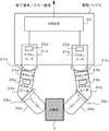
以下に、本発明の実施形態について図を用いて説明する。図1は本発明の力センサ付き電動ハンドの一例を説明する概略構成図である。図2は本発明の力センサ付き電動ハンドの他の例を説明する概略構成図である。図3は本発明の第1、第2、第4の実施形態の構成図である。図4は本発明の第3、第4の実施形態の構成図である。図5は本発明の第1、第2、第4の実施形態に関するフローチャートである。図6は本発明の第3、第4の実施形態に関するフローチャートである。なお、第1の実施形態は特許請求の範囲の請求項1の発明に対応する。第2の実施形態は請求項2の発明に対応する。第3の実施形態は請求項3の発明に対応する。第4の実施形態は請求項4の発明に対応する。 Embodiments of the present invention will be described below with reference to the drawings. FIG. 1 is a schematic configuration diagram illustrating an example of an electric hand with a force sensor according to the present invention. FIG. 2 is a schematic configuration diagram illustrating another example of the electric hand with a force sensor according to the present invention. FIG. 3 is a block diagram of the first, second and fourth embodiments of the present invention. FIG. 4 is a block diagram of the third and fourth embodiments of the present invention. FIG. 5 is a flowchart relating to the first, second and fourth embodiments of the present invention. FIG. 6 is a flowchart relating to the third and fourth embodiments of the present invention. The first embodiment corresponds to the invention of claim 1 of the claims. The second embodiment corresponds to the invention of claim 2. The third embodiment corresponds to the invention of
図1は、本発明の力センサ付き電動ハンドを示す。この電動ハンド1は開閉式のフィンガー14a,14bを2本持つ。アクチュエータ11は図示しないモータ、減速機、リニア駆動機構より成る。減速機は歯車で構成されるか、ないしは図示しないタイミングベルトで構成され、モータの回転を減速して図示しないリニア駆動機構に運動を伝達する。リニア駆動機構はモータの回転を直進動作に変換する機構であり、ラックピニオンや送りねじとナットやカム機構などと直線ガイド機構で構成される。 FIG. 1 shows an electric hand with a force sensor of the present invention. The electric hand 1 has two open /
リニア駆動機構によりフィンガー14a,14bが直進移動して開閉動作するが、フィンガー14a,14bの基部に力センサ13a,13bが設置されており、力センサ13a,13bにフィンガー14a,14bが取り付く構造になっている。矢印15aはフィンガー14aの可動方向を示し、矢印15bはフィンガー14bの可動方向を示している。フィンガー14a,14bが開閉移動して対象物3を挟んで把持する。対象物3がリング状などで穴がある場合は、穴の中にフィンガー14a,14bを入れて、フィンガー14a,14bを開く方向で対象物3を把持することもできる。 The
位置センサ12はアクチュエータ11の移動量を検出するセンサであり、一般的には回転検出器を使用してモータの回転角度を検出する。力センサ13a,13bにフィンガー14a,14bを取り付ける構造にすることにより、対象物3の形状に合わせてフィンガー14a,14bを交換することが出来るので便利である。力センサ13a,13bは開閉方向直線軸の力成分を検出する機能を持つことが望ましい。フィンガー14a,14bの基部には、把持力とモーメントが作用する。モーメントはフィンガー14a,14bの基部から把持位置までの距離に把持力を掛けた回転力であり、把持力が同じであってもフィンガー14a,14bの長さが異なるとモーメントは異なる。把持力を制御するためには、モーメントの影響を受けずに、開閉方向直線軸の力成分を検出する必要がある。 The
制御装置10は電動ハンド1を制御する装置である。制御装置10は図示しないロボットの制御装置からの把持指令に基づいて、本発明に係る対象物の把持動作を実行する。対象物の把持が完了した場合には完了信号をロボットの制御装置に送信し、対象物の把持を失敗した場合にはエラー信号をロボットの制御装置に送信する。なお、制御装置10は電動ハンド1内に設けることに限定されず、図示しないロボットの制御装置に内蔵してもよい。 The control device 10 is a device that controls the electric hand 1. The control device 10 executes a gripping operation of the object according to the present invention based on a gripping command from a robot control device (not shown). When the gripping of the object is completed, a completion signal is transmitted to the robot control device, and when the gripping of the object fails, an error signal is transmitted to the robot control device. The control device 10 is not limited to being provided in the electric hand 1, and may be built in a robot control device (not shown).
図1では力センサ13a,13bが2個設置されているが、2本のフィンガー14a,14bには向きが異なるが大きさの等しい把持力が作用するので、力センサ13a,13bは片方だけでも良い。 In FIG. 1, two
図2は、本発明の力センサ付き電動ハンドの別の実施例を示す。この電動ハンド2の場合、フィンガー26aとフィンガー26bの2本であるが、各フィンガー26a,26bは関節をそれぞれ2個持つ。フィンガー26aは、関節27a,関節28aを持つ。フィンガー26bは、関節27b,関節28bを持つ。 FIG. 2 shows another embodiment of the electric hand with a force sensor of the present invention. In the case of this electric hand 2, there are two
各関節27a,28a,27b,28bを駆動するアクチュエータがあり、関節27aはアクチュエータ21aによって回転し、関節28aはアクチュエータ24aによって回転し、関節27bはアクチュエータ21bによって回転し、関節28bはアクチュエータ24bによって回転する。このように、アクチュエータ21a,24a,21b,24bによって関節27a,28a,27b,28bが回転し、対象物3を電動ハンド2に備わったフィンガー26a,26bの先端で挟んで把持する。 There is an actuator that drives each joint 27a, 28a, 27b, 28b. The joint 27a is rotated by the
各アクチュエータ21a,24a,21b,24bは位置センサ(回転角度センサ22a,25a,22b,25b)を持っていて、関節の回転を検出できるようになっている。関節27a,28a,27b,28bを基部側からフィンガー26a,26bに向かって、第1関節27a,27b、第2関節28a,28bと呼ぶと、力センサ23a,23bは第1関節27a,27bと第2関節28a,28bの間に設置されている。力センサ23a,23bは第1関節27a,27bに作用するモーメント成分を検出する。この場合、対象物3の把持力は力センサ23a,23bにより直接検出できないが、力検出値と各関節の角度とフィンガー26a,26bの長さから把持力を計算して求められる。 Each
制御装置20は電動ハンド2を制御する装置である。制御装置20は図示しないロボットの制御装置からの把持指令に基づいて、本発明に係る対象物の把持動作を実行する。対象物の把持が完了した場合には完了信号をロボットの制御装置に送信し、対象物の把持を失敗した場合にはエラー信号をロボットの制御装置に送信する。なお、制御装置20は電動ハンド2内に設けることに限定されず、図示しないロボットの制御装置に内蔵してもよい。 The
図3に、本発明の第1、第2、第4の実施例の構成図を示す。アクチュエータ31はフィンガー部32を開閉移動して対象物を把持する。なおフィンガー部32は、対象物3(図1,図2参照)に接触するフィンガー14a,14b、26a,26b、および、フィンガー14a,14b、26a,26bがアクチュエータ31によって駆動されるための構成(例えば、ラックやギヤなど)を含む構成を意味する。 FIG. 3 shows a block diagram of the first, second and fourth embodiments of the present invention. The
フィンガー部32の移動量は位置センサ30で検出され、フィンガー部32に作用した把持力は力センサ33で検出される。アクチュエータ31はモータ(図示せず)を内蔵し、モータは駆動部34により駆動される。駆動部34は具体的にはアンプである。
位置制御部37は、指令位置の更新と位置フィードバック制御を行う。指令位置の更新は、単位周期、例えば4ms周期ごとに移動量を加算して新しい指令位置を算出し、指令位置が目標位置に到達すると移動量の加算を止めて、指令位置を目標位置に一致させるように、指令位置に対する移動量加算と停止を行う。位置フィードバック制御は位置センサ30の検出位置が指令位置に追従するようにフィードバック制御して駆動部34に駆動指令を出力し、アクチュエータ31のモータの回転を制御する。
力制御部39は、力検出値が力目標値に追従するようにフィードバック制御して駆動部34に駆動指令を出し、アクチュエータ31に内蔵される図示しないモータの回転を制御する。接触判別部36は、力検出値を監視して、力検出値が設定された力接触値以上になったとき、フィンガー部32のフィンガーが対象物に接触したと判断する。The amount of movement of the
The
The
ここで言う力検出値に関して説明する。力センサ33は、力が作用していない場合でも、力センサ33からの読取値がゼロで無いことがあり、その読取値をオフセットと呼ぶ。フィンガー部32のフィンガーが何も把持していないときに力センサ33の読取値をオフセットとして記憶しておく。力検出値は力センサ33の読取値から記憶したオフセットを差し引いた値を言う。このように、力検出値は、力センサ33の読取値そのものではなく、力センサ33に作用した外力を示す検出値である。 The force detection value referred to here will be described. In the
制御切替部35は、対象物にフィンガー部32のフィンガーが接触したと判別された場合に、駆動部34への駆動指令を位置制御部37から力制御部39に切り替える。力フィードバック制御では、フィードバックループの力ゲインを高くすると制御が不安定化しやすいので、力ゲインを余り高く出来ない。一般的に、力フィードバック制御では力目標値から力検出値を差し引いた力偏差量に力ゲインを掛けた値を速度指令としてアクチュエータを駆動する。フィンガーが対象物に接触していない場合に力制御部39でモータを駆動すると、力ゲインが小さく速度指令が小さいので移動速度が低速になる。さらに、力目標値に依存して速度が決まるので、力目標値が小さいと移動速度が極端に低速になる。従って、接触位置に到達するまで時間が掛かるという難点がある。一方、フィンガーが対象物に接触している場合、フィンガーが動くに従い、フィンガーと対象物に撓みが発生する。この撓み量と把持力は比例関係にあり、通常、わずかな撓み量で把持力は増大する。接触してからはモータのわずかな移動で把持力が増大するので、力制御部39で短時間で力目標値に達して把持動作を完了できる。そこで、接触していないときは位置制御部37でモータを駆動して速い速度でフィンガーを移動し、接触したと判別した時点で力制御部39に切り替える方法が非常に有利である。この方法により、把持動作全体を素早く、短時間で実行することができる。 The
完了判別部40は、力制御部39によって力検出値が力目標値に到達したことを判別し、完了信号をオンにする。ロボットはこの信号を確認して、次の動作に進むようにすれば、把持途中で動いて対象物を落としたり、あるいは把持完了後もしばらく停止していて時間を無駄にするなどの動作を防止できる。対象物が存在しない場合、フィンガー部32のフィンガーは位置制御部37により目標位置まで移動して停止する。目標位置は対象物を把持した位置を越えた位置に設定しておく。正常に把持した場合は目標位置の手前で停止するが、把持できない場合は目標位置に到達して停止する。エラー判別部38は、この状態を判別して、把持が正常に出来なかった場合にエラー信号をオンにする。ロボットはこの信号を確認することにより、通常の動作を中断してエラー対応処理を実行することができる。 The
図4に、本発明の第3、第4の実施例の構成図を示す。図3との違いは、力制御部39がなく、その代わりに接触停止部59が追加されている。接触判別部56により、フィンガー部52のフィンガーが対象物に接触したと判別されると、接触停止部59は位置制御部57に対して即時に移動を停止させる指令を出して、完了信号をオンにする。 FIG. 4 shows a configuration diagram of the third and fourth embodiments of the present invention. The difference from FIG. 3 is that there is no
図3を用いて説明した接触を判別すると力制御部39に切り替える方法では、通常、力接触値を力目標値より小さく、例えば力目標値の20%程度の値に設定する。そうすると、位置制御から力制御に早い時点で切り替わるので、力フィードバック制御の応答がスムーズになり、把持力が大きくオーバーシュートせずに力目標値に到達する。しかし、力目標値が非常に小さい場合、力接触値が更に小さくなるので、振動や検出ばらつきなどにより力検出値が力接触値を上回り、実際には接触していないのに接触したと判別する誤動作が起き易い。また、力フィードバック制御におけるモータの移動速度が遅くなり、応答時間が長くなる。これに対して、接触停止部59では、力接触値を力目標値に近い値に設定することにより、接触判別の誤動作を防止できると共に、位置制御部57により適切な速度を指定できる。この方法は、対象物が柔らかい場合の把持に特に有効である。 In the method of switching to the
接触停止部59により即時に移動を停止させる方法を説明する。一つの方法として、位置フィードバック制御に入力する指令位置を停止する方法があり、これはモータが実際に停止するまでの惰走量が大きい。一般的に位置フィードバック制御では、指令位置から検出位置を差し引いた位置偏差量に位置ゲインを掛けた値が移動速度になっており、指令位置を停止した場合、そのときの位置偏差量が惰走量になる。もう一つの方法として、モータ駆動電圧をゼロにする方法があり、これは惰走量がかなり小さくなるが、ゼロにはならない。別の方法として位置偏差量を一旦ゼロにクリアし、以後は通常の位置フィードバック制御にする方法がある。この方法は接触を判別した位置に最終的に停止するので惰走量がゼロになる。あるいは、位置偏差量をゼロにする代わりに、適当な惰走値をセットして、以後は通常の位置フィードバック制御にすると、接触を判別した位置に惰走値を加算した位置に最終的に停止する。停止するまでの惰走量が小さいほど、減速方向の加速度が大きいので、減速時のショックとアクチュエータに掛かる負荷が大きくなる。通常は、アクチュエータが耐えられる程度に応じて、適切な停止方法を採用する。 A method for stopping the movement immediately by the
図5に、本発明の第1、第2、第4の実施例のフローを示す。把持指令がオンになると、単位周期ごとに移動量を加算して指令位置を更新し、指令位置を位置フィードバック制御に入力する。指令位置が目標位置に到達していない場合、力検出値が力接触値より小さければ指令位置の更新を行う。力検出値が力接触値以上であれば、フィンガーと対象物が接触したことになるので、位置制御から力制御に切り替える。力制御では力目標値に追従するようにフィードバック制御が行われており、力検出値が力目標値に到達するまで待つ。力検出値が力目標値に到達すれば、完了信号をオンにして把持指令に対する動作を終了する。指令位置の更新を行っているときに、目標位置に到達した場合、移動を停止し、把持が正常に出来なかったのでエラー信号をオンにして、把持指令に対する動作を終了する。 FIG. 5 shows the flow of the first, second and fourth embodiments of the present invention. When the grip command is turned on, the command position is updated by adding the movement amount for each unit cycle, and the command position is input to the position feedback control. When the command position has not reached the target position, the command position is updated if the force detection value is smaller than the force contact value. If the force detection value is equal to or greater than the force contact value, the finger and the object are in contact, so the position control is switched to the force control. In force control, feedback control is performed so as to follow the force target value, and the process waits until the force detection value reaches the force target value. When the force detection value reaches the force target value, the completion signal is turned on and the operation in response to the grip command is ended. If the target position is reached while the command position is being updated, the movement is stopped, and gripping cannot be performed normally. Therefore, an error signal is turned on, and the operation for the grip command is terminated.
以下、各ステップに従って説明する。
●[ステップSA01]把持指令がオンか否か判断し、把持指令がオンの場合(YES)ステップSA02へ移行し、オンではない場合(NO)には把持指令がオンになるのを待つ。
●[ステップSA02]単位周期ごとに移動量を加算して指令位置を更新し、指令位置を位置フィードバック制御に入力する。
●[ステップSA03]指令位置が目標位置に到達したか否か判断し、目標位置に到達した場合(YES)ステップSA04へ移行し、目標位置に到達していない場合(NO)ステップSA06へ移行する。
●[ステップSA04]移動を停止する。つまり、指令位置を目標位置に一致させ、位置フィードバック制御によりモータは目標位置で停止する。
●[ステップSA05]エラー信号をオンして、把持指令に対する動作を終了する。
●[ステップSA06]力検出値が力接触値より小さければ(NO)ステップSA02に戻り、指令位置の更新を行う。力検出値が力接触値以上であれば(YES)、ステップSA07に移行する。
●[ステップSA07]フィンガーと対象物が接触したことになるので、位置制御から力制御に切替える。
●[ステップSA08]力検出値が力目標値に到達したか否か判断し、到達した場合(YES)、ステップSA09へ移行し、到達していない場合(NO)、力検出値が力目標値以上になるのを待って、ステップSA09へ移行する。
●[ステップSA09]完了信号をオンにして把持指令に対する動作を終了する。Hereinafter, it demonstrates according to each step.
[Step SA01] It is determined whether or not the gripping command is on. If the gripping command is on (YES), the process proceeds to step SA02. If the gripping command is not on (NO), the system waits for the gripping command to be turned on.
[Step SA02] The command position is updated by adding the movement amount for each unit cycle, and the command position is input to the position feedback control.
[Step SA03] It is determined whether or not the command position has reached the target position. If the target position has been reached (YES), the process proceeds to Step SA04. If the command position has not been reached (NO), the process proceeds to Step SA06. .
[Step SA04] The movement is stopped. That is, the command position is matched with the target position, and the motor stops at the target position by position feedback control.
[Step SA05] The error signal is turned on, and the operation for the grip command is ended.
[Step SA06] If the force detection value is smaller than the force contact value (NO), the process returns to Step SA02 to update the command position. If the force detection value is greater than or equal to the force contact value (YES), the process proceeds to step SA07.
[Step SA07] Since the finger and the object are in contact, the position control is switched to the force control.
[Step SA08] It is determined whether or not the force detection value has reached the force target value. If the force detection value has been reached (YES), the process proceeds to Step SA09, and if it has not reached (NO), the force detection value is the force target value. After waiting for the above, the process proceeds to step SA09.
[Step SA09] The completion signal is turned on to end the operation in response to the grip command.
図6に、本発明の第3、第4の実施例のフローを示す。図5のフローとの相違は、力検出値が力接触値以上であれば、力制御に切り替えるのではなく、移動停止を実行する点にある。移動停止の方法には、前述したように幾つかの方法があり、そのうちの適切な方法を選択して実行すれば良い。 FIG. 6 shows a flow of the third and fourth embodiments of the present invention. The difference from the flow of FIG. 5 is that if the force detection value is equal to or greater than the force contact value, the movement is stopped instead of switching to force control. As described above, there are several methods for stopping the movement, and an appropriate method may be selected and executed.
以下、各ステップに従って説明する。
●[ステップSB01]把持指令がオンか否か判断し、把持指令がオンの場合(YES)ステップSB02へ移行し、オンではない場合(NO)には把持指令がオンになるのを待つ。
●[ステップSB02]単位周期ごとに移動量を加算して指令位置を更新し、指令位置を位置フィードバック制御に入力する。
●[ステップSB03]指令位置が目標位置に到達したか否か判断し、目標位置に到達した場合(YES)ステップSB04へ移行し、目標位置に到達していない場合(NO)ステップSB06へ移行する。
●[ステップSB04]移動を停止する。つまり、指令位置を目標位置に一致させ、位置フィードバック制御によりモータは目標位置で停止する。
●[ステップSB05]エラー信号をオンして、把持指令に対する動作を終了する。
●[ステップSB06]力検出値が力接触値より小さければ(NO)ステップSB02に戻り、指令位置の更新を行う。力検出値が力接触値以上であれば(YES)、ステップSB07に移行する。
●[ステップSB07]移動を停止する。つまり、フィンガーを移動させるアクチュエータに内蔵されるモータの駆動を停止する。
●[ステップSB08]完了信号をオンにして把持指令に対する動作を終了する。
なお、図5,図6のフローチャートの処理は図1の制御装置10や図2の制御装置20において実行される。目標位置、力接触値、力目標値のデータは制御装置10あるいは制御装置20のメモリに予め格納しておくことで、図5,図6の処理を実行することができる。Hereinafter, it demonstrates according to each step.
[Step SB01] It is determined whether or not the grip command is on. If the grip command is on (YES), the process proceeds to step SB02. If not (NO), the process waits for the grip command to be turned on.
[Step SB02] The command position is updated by adding the movement amount for each unit cycle, and the command position is input to the position feedback control.
[Step SB03] It is determined whether or not the command position has reached the target position. If the target position has been reached (YES), the process proceeds to Step SB04, and if the target position has not been reached (NO), the process proceeds to Step SB06. .
[Step SB04] The movement is stopped. That is, the command position is matched with the target position, and the motor stops at the target position by position feedback control.
[Step SB05] The error signal is turned on, and the operation for the grip command is ended.
[Step SB06] If the detected force value is smaller than the force contact value (NO), the process returns to Step SB02 to update the command position. If the force detection value is equal to or greater than the force contact value (YES), the process proceeds to step SB07.
[Step SB07] The movement is stopped. That is, the drive of the motor built in the actuator which moves a finger is stopped.
[Step SB08] The completion signal is turned on to end the operation in response to the grip command.
5 and 6 is executed by the control device 10 of FIG. 1 or the
1 電動ハンド
10 制御装置
11 アクチュエータ
12 位置センサ
13a,13b 力センサ
14a,14b フィンガー
15a,15b 可動方向
2 電動ハンド
20 制御装置
21a,21b アクチュエータ
22a,22b 回転センサ
23a,23b 力センサ
24a,24b アクチュエータ
25a,25b 回転センサ
26a,26b フィンガー
27a,27b 第1関節
28a,28b 第2関節
3 対象物
30 位置センサ
31 アクチュエータ
32 フィンガー部
33 力センサ
34 駆動部
35 制御切替部
36 接触判別部
37 位置制御部
38 エラー判別部
39 力制御部
40 完了判別部
50 位置センサ
51 アクチュエータ
52 フィンガー部
53 力センサ
54 駆動部
56 接触判別部
57 位置制御部
58 エラー判別部
59 接触停止部DESCRIPTION OF SYMBOLS 1 Electric hand 10
2
3 objects
DESCRIPTION OF
50
56
ロボットの基本動作は対象物を把持して搬送することであり、対象物を把持するために、複数のフィンガーで対象物を挟む構造のハンドが一般的に使用される。対象物を把持する際、把持力が大き過ぎると対象物をつぶしてしまい、小さ過ぎると搬送途中で対象物を落下させることがあるので、対象物の重さや硬さに応じて、把持力を調整できるハンドが要求される。
ロボットは、ハンドの把持動作が完了してから搬送などの次の動作に移る必要があるので、把持動作の完了を確認するための完了信号が必要とされる。また、規定位置に対象物がないために対象物を把持できない場合は、ロボットは通常動作を中断してエラー対応処理をする必要があるので、対象物を把持できなかったことを示すエラー信号が必要とされる。The basic operation of the robot is to convey to grip an object, in order to grip an object, the hand structure sandwiching an objectwith a plurality of fingersover is generally used. When gripping an object, if the gripping force is too large, the object will be crushed. An adjustable hand is required.
Since the robot needs to move to the next operation such as conveyance after the gripping operation of the hand is completed, a completion signal for confirming the completion of the gripping operation is required. Also, if the target cannot be gripped because there is no target at the specified position, the robot must interrupt normal operation and perform error handling processing, so an error signal indicating that the target could not be gripped will be displayed. Needed.
本願の請求項1に係る発明は、開閉動作して対象物を把持する複数のフィンガーを有するフィンガー部と、前記フィンガー部を駆動するアクチュエータと、前記フィンガー部に設けられ、前記フィンガー部の開閉方向に作用する力を検出する少なくとも1個の力センサと、前記フィンガー部の移動量を検出する位置センサと、前記アクチュエータを駆動する駆動部と、把持指令がオンになった場合に、前記位置センサからの位置検出値による位置フィードバック制御を行って前記駆動部に駆動指令を出力し前記アクチュエータを駆動し、設定された位置目標値に向かって前記フィンガー部を移動させる位置制御部と、前記力センサからの力検出値による力フィードバック制御を行って前記駆動部に駆動指令を出力し前記アクチュエータを駆動し、前記力検出値が設定された力目標値に一致するように前記アクチュエータを駆動する力制御部と、前記力検出値が設定された力接触値を超えたことを検出して前記フィンガーが前記対象物に接触したことを判別する接触判別部と、前記接触判別部が接触したと判別した場合に前記駆動部に与える駆動指令を前記位置制御部から前記力制御部に切り替える制御切替部とを備えることを特徴とする電動ハンドである。
請求項2に係る発明は、前記力制御部により前記アクチュエータを駆動しているときに、前記力検出値が前記力目標値に到達したことを判別して完了信号を出力する完了判別部を備えることを特徴とする請求項1に記載の電動ハンドである。The invention according to claim 1 of the present application is provided with a finger portion having a plurality of fingers for gripping an object by opening / closing operation, an actuator for driving the finger portion, and an opening / closing direction of the finger portion. At least one force sensor for detecting a force acting on the finger, a position sensor for detecting the movement amount of the finger part, a drive part for driving the actuator, and the position sensor when a gripping command is turned on. A position control unit that performs position feedback control based on a position detection value from the drive unit, outputs a drive command to the drive unit, drives the actuator, and moves the finger unit toward a set position target value; and the force sensor Force feedback control is performed based on the force detection value from the drive, and a drive command is output to the drive unit to drive the actuator A force control section for driving the actuator to match the force target value the force detection value is set,said fingerover it is detected that the force detection value exceeds the set force contact value A contact determination unit that determines that the object has contacted; a control switching unit that switches a drive command to be given to the drive unit from the position control unit to the force control unit when it is determined that the contact determination unit has contacted; It is an electric hand characterized by comprising.
The invention according to claim 2 includes a completion determination unit that determines that the force detection value has reached the force target value and outputs a completion signal when the actuator is driven by the force control unit. The electric hand according to claim 1.
請求項3に係る発明は、開閉動作して対象物を把持する複数のフィンガーを有するフィンガー部と、前記フィンガー部を駆動するアクチュエータと、前記フィンガー部に設けられ、前記フィンガー部の開閉方向に作用する力を検出する少なくとも1個の力センサと、 前記フィンガー部の移動量を検出する位置センサと、前記アクチュエータを駆動する駆動部と、把持指令がオンになった場合に、前記位置センサからの位置検出値による位置フィードバック制御を行って前記駆動部に駆動指令を出力し前記アクチュエータを駆動し、設定された位置目標値に向かって前記フィンガー部を移動させる位置制御部と、前記力センサからの力検出値が設定された力接触値を超えたことを検出して前記フィンガーが前記対象物に接触したことを判別する接触判別部と、前記接触判別部が接触したと判別した場合に前記位置制御部に停止指令を出して前記アクチュエータの動きを停止し、完了信号を出力する接触停止部とを備えることを特徴とする電動ハンドである。
請求項4に係る発明は、前記位置制御部により前記フィンガー部が前記位置目標値に到達した場合、前記対象物を把持しなかったと判別してエラー信号を出力するエラー判別部を備えることを特徴とする請求項1〜3のいずれか一つに記載の電動ハンドである。According to a third aspect of the present invention, there is provideda finger part having a plurality of fingers for gripping an object by opening / closing operation, an actuator for driving the finger part, and provided in the finger part and acting in an opening / closing direction of the finger part. At least one force sensor that detects the force to be moved, a position sensor that detects the amount of movement of the finger part, a drive part that drives the actuator, and when the grip command is turned on, A position control unit that performs position feedback control based on a position detection value, outputs a drive command to the drive unit, drives the actuator, and moves the finger unit toward a set position target value; and from the force sensor it is detected that the force detection value exceeds the set force contact value to determine that the fingerover is in contact with the object A contact determining unit; and a contact stopping unit that outputs a stop command to stop the movement of the actuator by outputting a stop command to the position control unit when it is determined that the contact determining unit is in contact with the contact determining unit. It is an electric hand.
The invention according to claim 4 includes an error determination unit that determines that the object has not been gripped and outputs an error signal when the finger unit reaches the position target value by the position control unit. It is an electric hand as described in any one of Claims 1-3.
Claims (4)
Translated fromJapanese前記フィンガー部を駆動するアクチュエータと、
前記フィンガー部に設けられ、前記フィンガー部の開閉方向に作用する力を検出する少なくとも1個の力センサと、
前記フィンガー部の移動量を検出する位置センサと、
前記アクチュエータを駆動する駆動部と、
把持指令がオンになった場合に、前記位置センサからの位置検出値による位置フィードバック制御を行って前記駆動部に駆動指令を出力し前記アクチュエータを駆動し、設定された位置目標値に向かって前記フィンガー部を移動させる位置制御部と、
前記力センサからの力検出値による力フィードバック制御を行って前記駆動部に駆動指令を出力し前記アクチュエータを駆動し、前記力検出値が設定された力目標値に一致するように前記アクチュエータを駆動する力制御部と、
前記力検出値が設定された力接触値を超えたことを検出して前記フィンガー部が前記対象物に接触したことを判別する接触判別部と、
前記接触判別部が接触したと判別した場合に前記駆動部に与える駆動指令を前記位置制御部から前記力制御部に切り替える制御切替部とを備えることを特徴とする電動ハンド。In an electric hand that has a plurality of finger parts and grips an object by its opening and closing operation,
An actuator for driving the finger part;
At least one force sensor that is provided in the finger portion and detects a force acting in an opening and closing direction of the finger portion;
A position sensor for detecting the amount of movement of the finger part;
A drive unit for driving the actuator;
When the grip command is turned on, position feedback control based on a position detection value from the position sensor is performed, a drive command is output to the drive unit, the actuator is driven, and the position target value is set toward the set position target value. A position control unit for moving the finger unit;
Force feedback control is performed based on a force detection value from the force sensor, a drive command is output to the drive unit to drive the actuator, and the actuator is driven so that the force detection value matches a set force target value. A force control unit to
A contact determination unit that detects that the force detection value exceeds a set force contact value and determines that the finger unit has contacted the object; and
An electric hand comprising: a control switching unit that switches a drive command to be given to the drive unit from the position control unit to the force control unit when it is determined that the contact determination unit has made contact.
前記フィンガー部を駆動するアクチュエータと、
前記フィンガー部に設けられ、前記フィンガー部の開閉方向に作用する力を検出する少なくとも1個の力センサと、
前記フィンガー部の移動量を検出する位置センサと、
前記アクチュエータを駆動する駆動部と、
把持指令がオンになった場合に、前記位置センサからの位置検出値による位置フィードバック制御を行って前記駆動部に駆動指令を出力し前記アクチュエータを駆動し、設定された位置目標値に向かって前記フィンガー部を移動させる位置制御部と、
前記力センサからの力検出値が設定された力接触値を超えたことを検出して前記フィンガー部が前記対象物に接触したことを判別する接触判別部と、
前記接触判別部が接触したと判別した場合に前記位置制御部に停止指令を出して前記アクチュエータの動きを停止し、完了信号を出力する接触停止部とを備えることを特徴とする電動ハンド。In an electric hand that has a plurality of finger parts and grips an object by its opening and closing operation,
An actuator for driving the finger part;
At least one force sensor that is provided in the finger portion and detects a force acting in an opening and closing direction of the finger portion;
A position sensor for detecting the amount of movement of the finger part;
A drive unit for driving the actuator;
When the grip command is turned on, position feedback control based on a position detection value from the position sensor is performed, a drive command is output to the drive unit, the actuator is driven, and the position target value is set toward the set position target value. A position control unit for moving the finger unit;
A contact determination unit that detects that a force detection value from the force sensor exceeds a set force contact value and determines that the finger unit has contacted the object; and
An electric hand comprising: a contact stop unit that issues a stop command to the position control unit to stop the movement of the actuator and outputs a completion signal when it is determined that the contact determination unit has made contact.
Priority Applications (4)
| Application Number | Priority Date | Filing Date | Title |
|---|---|---|---|
| JP2012262861AJP2014108466A (en) | 2012-11-30 | 2012-11-30 | Electric hand with force sensor |
| DE102013113044.5ADE102013113044A1 (en) | 2012-11-30 | 2013-11-26 | Electric gripping hand with force sensor |
| US14/091,403US20140156066A1 (en) | 2012-11-30 | 2013-11-27 | Electric hand with a force sensor |
| CN201310632280.3ACN103846923A (en) | 2012-11-30 | 2013-11-29 | Electric hand with force sensor |
Applications Claiming Priority (1)
| Application Number | Priority Date | Filing Date | Title |
|---|---|---|---|
| JP2012262861AJP2014108466A (en) | 2012-11-30 | 2012-11-30 | Electric hand with force sensor |
Publications (1)
| Publication Number | Publication Date |
|---|---|
| JP2014108466Atrue JP2014108466A (en) | 2014-06-12 |
Family
ID=50726154
Family Applications (1)
| Application Number | Title | Priority Date | Filing Date |
|---|---|---|---|
| JP2012262861APendingJP2014108466A (en) | 2012-11-30 | 2012-11-30 | Electric hand with force sensor |
Country Status (4)
| Country | Link |
|---|---|
| US (1) | US20140156066A1 (en) |
| JP (1) | JP2014108466A (en) |
| CN (1) | CN103846923A (en) |
| DE (1) | DE102013113044A1 (en) |
Cited By (15)
| Publication number | Priority date | Publication date | Assignee | Title |
|---|---|---|---|---|
| JP2016035740A (en)* | 2014-07-31 | 2016-03-17 | ザ・ボーイング・カンパニーTheBoeing Company | Electronic stopper in actuator control |
| WO2016073367A1 (en)* | 2014-11-03 | 2016-05-12 | The Board Of Trustees Of The Leland Stanford Junior University | Position/force control of a flexible manipulator under model-less control |
| KR20160117930A (en)* | 2015-03-24 | 2016-10-11 | 하이윈 테크놀로지스 코포레이션 | Electric gripper system and control method thereof |
| US9488971B2 (en) | 2013-03-11 | 2016-11-08 | The Board Of Trustees Of The Leland Stanford Junior University | Model-less control for flexible manipulators |
| JP2016196077A (en)* | 2015-04-06 | 2016-11-24 | キヤノン株式会社 | Information processor, information processing method, and program |
| KR101790946B1 (en)* | 2015-11-24 | 2017-10-27 | 재단법인대구경북과학기술원 | Controlling apparatus for gripper using force sensor and method thereof |
| WO2018212189A1 (en)* | 2017-05-15 | 2018-11-22 | Thk株式会社 | Gripping system |
| JP2019141987A (en)* | 2018-02-23 | 2019-08-29 | セイコーエプソン株式会社 | Control device, end effector, robot and control method |
| JP2020015145A (en)* | 2018-07-26 | 2020-01-30 | キヤノン株式会社 | Robot hand and force sensor |
| JP2020104188A (en)* | 2018-12-26 | 2020-07-09 | 株式会社デンソーウェーブ | Electric gripper device, and electric gripper device control program |
| JP2020138293A (en)* | 2019-02-28 | 2020-09-03 | セイコーエプソン株式会社 | Robot system and control method |
| JP2020138292A (en)* | 2019-02-28 | 2020-09-03 | セイコーエプソン株式会社 | Robot system and control method |
| WO2022123849A1 (en)* | 2020-12-08 | 2022-06-16 | オムロン株式会社 | Robot, gripping force control device, gripping force control method, and gripping force control program |
| WO2023022195A1 (en)* | 2021-08-20 | 2023-02-23 | ミネベアミツミ株式会社 | Gripping device, and method for controlling gripping device |
| WO2023145675A1 (en)* | 2022-01-27 | 2023-08-03 | ミネベアミツミ株式会社 | Gripping device, gripping system, and method for controlling gripping device |
Families Citing this family (43)
| Publication number | Priority date | Publication date | Assignee | Title |
|---|---|---|---|---|
| JP6468871B2 (en) | 2015-02-03 | 2019-02-13 | キヤノン株式会社 | Robot hand control method and robot apparatus |
| DE102015003696A1 (en)* | 2015-03-20 | 2016-09-22 | Kuka Roboter Gmbh | Releasing an operation of a machine |
| CN106142142A (en)* | 2015-04-08 | 2016-11-23 | 鸿富锦精密工业(深圳)有限公司 | Manipulator |
| US9889564B2 (en)* | 2015-07-08 | 2018-02-13 | Empire Technology Development Llc | Stable grasp point selection for robotic grippers with machine vision and ultrasound beam forming |
| US10272568B2 (en)* | 2015-09-17 | 2019-04-30 | Canon Kabushiki Kaisha | Robot apparatus, robot controlling method, program, recording medium, and assembly manufacturing method |
| JP6250900B2 (en) | 2015-09-29 | 2017-12-20 | ファナック株式会社 | Method of machining a workpiece by cooperation between a machine tool and a robot |
| CN108136581B (en)* | 2015-10-05 | 2021-11-02 | 马丁·齐默尔 | Clamping device with integrated control |
| DE102016011761A1 (en) | 2016-10-04 | 2018-04-05 | Günther Zimmer | Gripping device with switching module |
| US10252421B2 (en) | 2015-10-06 | 2019-04-09 | Mtm Robotics Llc | Self-contained modular manufacturing tool |
| US10025299B2 (en) | 2015-10-06 | 2018-07-17 | Mtm Robotics, Llc | System and method for self-contained modular manufacturing device having nested controllers |
| US10220516B2 (en) | 2015-10-06 | 2019-03-05 | Mtm Robotics, Llc | System and method for self-contained independently controlled modular manufacturing tools |
| US10022872B2 (en) | 2015-10-06 | 2018-07-17 | Mtm Robotics, Llc | Self-contained modular manufacturing tool responsive to locally stored historical data |
| DE102015220517A1 (en)* | 2015-10-21 | 2017-04-27 | Kuka Systems Gmbh | MRK system and method for controlling a MRK system |
| CN105563502B (en)* | 2016-02-25 | 2017-06-30 | 渤海大学 | A clamping device, a hand-operated device, and a control method for the clamping device and the hand-operated device with force/position hybrid compliant control |
| CN105690416B (en)* | 2016-04-03 | 2018-09-04 | 渤海大学 | A kind of robotic gripping apparatus and control method |
| US9827670B1 (en)* | 2016-05-24 | 2017-11-28 | X Development Llc | Coaxial finger face and base encoding |
| DE102017210213A1 (en)* | 2017-06-19 | 2018-12-20 | Kuka Deutschland Gmbh | Gripper with a sensor on a gearbox bearing of the gripper |
| US10836034B2 (en)* | 2017-07-10 | 2020-11-17 | Kindred Systems Inc. | Systems, devices, articles, and methods for prehension of items |
| JP2019018280A (en)* | 2017-07-14 | 2019-02-07 | Thk株式会社 | Holding system |
| JP7427358B2 (en)* | 2017-07-20 | 2024-02-05 | キヤノン株式会社 | Robot system, article manufacturing method, control method, control program, and recording medium |
| JP6996177B2 (en)* | 2017-09-11 | 2022-01-17 | セイコーエプソン株式会社 | Robot, offset correction device for force sensor, and robot control method |
| DE102017126564A1 (en)* | 2017-11-13 | 2019-05-16 | Fipa Holding Gmbh | GRAB |
| DE102017220479B3 (en) | 2017-11-16 | 2019-03-14 | Festo Ag & Co. Kg | gripping device |
| DE102018203626B3 (en) | 2018-03-09 | 2019-08-14 | Kuka Systems Gmbh | Multiple gripper device for a robot |
| US11999051B2 (en)* | 2018-03-27 | 2024-06-04 | Sony Corporation | Control device, control method, and program |
| DE102018205642A1 (en)* | 2018-04-13 | 2019-10-17 | Festo Ag & Co. Kg | Interface module for a gripping device and robot equipped therewith |
| JP7124440B2 (en)* | 2018-05-23 | 2022-08-24 | セイコーエプソン株式会社 | Robot controller and robot system |
| AT521483B1 (en)* | 2018-08-21 | 2020-02-15 | Engel Austria Gmbh | handling device |
| CN109048956B (en)* | 2018-08-30 | 2019-06-07 | 南京禹智智能科技有限公司 | An industrial robot loading and unloading clamping mechanism |
| DE102019107851B4 (en)* | 2019-03-27 | 2022-06-23 | Franka Emika Gmbh | Robot gripper and method for operating a robot gripper |
| DE102019108241B3 (en) | 2019-03-29 | 2020-08-06 | Franka Emika Gmbh | Intuitive setting of force control for robot manipulators |
| US20210031373A1 (en) | 2019-08-02 | 2021-02-04 | Dextrous Robotics, Inc. | Robotic manipulators |
| CN111098309A (en)* | 2020-01-06 | 2020-05-05 | 江南大学 | A kind of mechanical arm hybrid control method, device and system |
| CN111805545B (en)* | 2020-07-13 | 2021-06-08 | 河北省科学院应用数学研究所 | Dexterous hand control method and device and terminal equipment |
| CN114619442B (en)* | 2020-12-08 | 2023-06-20 | 山东新松工业软件研究院股份有限公司 | Control method and system for manipulator with multiple joints of fingers |
| CN113262050A (en)* | 2021-05-13 | 2021-08-17 | 北京铸正机器人有限公司 | Two-degree-of-freedom tail end execution device |
| CN113618709B (en)* | 2021-07-07 | 2023-12-29 | 浙江大学 | Multi-mode force control nondestructive grabbing device for intelligent production line |
| JP2023029075A (en)* | 2021-08-20 | 2023-03-03 | ミネベアミツミ株式会社 | Gripping device and gripping device control method |
| DE112021007930T5 (en)* | 2021-09-14 | 2024-04-18 | Fanuc Corporation | Robot system and a robot control device |
| GB202113167D0 (en) | 2021-09-15 | 2021-10-27 | Ocado Innovation Ltd | Controlling a gripper assembly of a robotic manipulator |
| US11845184B2 (en) | 2022-04-18 | 2023-12-19 | Dextrous Robotics, Inc. | System and/or method for grasping objects |
| JP2024046251A (en)* | 2022-09-22 | 2024-04-03 | セイコーエプソン株式会社 | GRIP DEVICE, ROBOT, AND METHOD FOR CONTROLLING GRIP DEVICE |
| FR3143966A1 (en)* | 2022-12-27 | 2024-06-28 | Robocath | Control of a robotic system actuator for driving an elongated flexible medical instrument |
Citations (9)
| Publication number | Priority date | Publication date | Assignee | Title |
|---|---|---|---|---|
| JPH04146094A (en)* | 1990-10-08 | 1992-05-20 | Matsushita Electric Ind Co Ltd | Servo hand and work holding method |
| JPH058188A (en)* | 1991-07-05 | 1993-01-19 | Fujitsu Ltd | Gripping device |
| JPH06126684A (en)* | 1992-10-21 | 1994-05-10 | Mitsubishi Electric Corp | Object gripping device and control method thereof |
| JP2000071189A (en)* | 1998-08-27 | 2000-03-07 | Eastman Kodak Co | Workpiece acquisition determination method for robot grip device |
| JP3124519B2 (en)* | 1998-07-23 | 2001-01-15 | セイコー精機株式会社 | Robot controller with control system mode switching function |
| JP2008183629A (en)* | 2007-01-26 | 2008-08-14 | Toyota Motor Corp | Robot and robot control apparatus and control method |
| JP2009066685A (en)* | 2007-09-11 | 2009-04-02 | Sony Corp | Robot device, and control method for robot device |
| JP2010069584A (en)* | 2008-09-19 | 2010-04-02 | Yaskawa Electric Corp | Device and method for controlling manipulator |
| JP2012236237A (en)* | 2011-05-10 | 2012-12-06 | Seiko Epson Corp | Robot hand and robot |
Family Cites Families (14)
| Publication number | Priority date | Publication date | Assignee | Title |
|---|---|---|---|---|
| US5762390A (en)* | 1996-07-16 | 1998-06-09 | Universite Laval | Underactuated mechanical finger with return actuation |
| US6505870B1 (en)* | 2000-05-30 | 2003-01-14 | UNIVERSITé LAVAL | Actuation system for highly underactuated gripping mechanism |
| CA2500005C (en)* | 2002-09-26 | 2011-12-06 | Barrett Technology, Inc. | Intelligent, self-contained robotic hand |
| JP5122134B2 (en)* | 2004-03-31 | 2013-01-16 | 独立行政法人科学技術振興機構 | Robot hand |
| JP2006159320A (en)* | 2004-12-03 | 2006-06-22 | Sharp Corp | Robot hand |
| US7361197B2 (en)* | 2005-04-01 | 2008-04-22 | Rex Clayton Winfrey | Prosthetic hand having a conformal, compliant grip and opposable, functional thumb |
| JP4918004B2 (en)* | 2006-11-24 | 2012-04-18 | パナソニック株式会社 | Multi-fingered robot hand |
| KR101550841B1 (en)* | 2008-12-22 | 2015-09-09 | 삼성전자 주식회사 | Robot hand and humanoid robot equipped with it |
| US8504198B2 (en)* | 2009-05-14 | 2013-08-06 | Honda Motor Co., Ltd. | Robot hand and control system, control method and control program for the same |
| US8483880B2 (en)* | 2009-07-22 | 2013-07-09 | The Shadow Robot Company Limited | Robotic hand |
| KR101674894B1 (en)* | 2009-12-21 | 2016-11-10 | 삼성전자 주식회사 | Industrial multi-freedom gripper |
| JP5586991B2 (en) | 2010-03-09 | 2014-09-10 | キヤノン株式会社 | Gripping device control method and gripping system |
| JP5815923B2 (en) | 2010-03-19 | 2015-11-17 | 株式会社デンソーウェーブ | Electric hand |
| US8504205B2 (en)* | 2011-03-17 | 2013-08-06 | Harris Corporation | Robotic grasping device with multi-force sensing at base of fingers |
- 2012
- 2012-11-30JPJP2012262861Apatent/JP2014108466A/enactivePending
- 2013
- 2013-11-26DEDE102013113044.5Apatent/DE102013113044A1/ennot_activeWithdrawn
- 2013-11-27USUS14/091,403patent/US20140156066A1/ennot_activeAbandoned
- 2013-11-29CNCN201310632280.3Apatent/CN103846923A/enactivePending
Patent Citations (9)
| Publication number | Priority date | Publication date | Assignee | Title |
|---|---|---|---|---|
| JPH04146094A (en)* | 1990-10-08 | 1992-05-20 | Matsushita Electric Ind Co Ltd | Servo hand and work holding method |
| JPH058188A (en)* | 1991-07-05 | 1993-01-19 | Fujitsu Ltd | Gripping device |
| JPH06126684A (en)* | 1992-10-21 | 1994-05-10 | Mitsubishi Electric Corp | Object gripping device and control method thereof |
| JP3124519B2 (en)* | 1998-07-23 | 2001-01-15 | セイコー精機株式会社 | Robot controller with control system mode switching function |
| JP2000071189A (en)* | 1998-08-27 | 2000-03-07 | Eastman Kodak Co | Workpiece acquisition determination method for robot grip device |
| JP2008183629A (en)* | 2007-01-26 | 2008-08-14 | Toyota Motor Corp | Robot and robot control apparatus and control method |
| JP2009066685A (en)* | 2007-09-11 | 2009-04-02 | Sony Corp | Robot device, and control method for robot device |
| JP2010069584A (en)* | 2008-09-19 | 2010-04-02 | Yaskawa Electric Corp | Device and method for controlling manipulator |
| JP2012236237A (en)* | 2011-05-10 | 2012-12-06 | Seiko Epson Corp | Robot hand and robot |
Cited By (29)
| Publication number | Priority date | Publication date | Assignee | Title |
|---|---|---|---|---|
| US9488971B2 (en) | 2013-03-11 | 2016-11-08 | The Board Of Trustees Of The Leland Stanford Junior University | Model-less control for flexible manipulators |
| JP2016035740A (en)* | 2014-07-31 | 2016-03-17 | ザ・ボーイング・カンパニーTheBoeing Company | Electronic stopper in actuator control |
| US11402858B2 (en) | 2014-07-31 | 2022-08-02 | The Boeing Company | Electronic stopper in actuator control |
| US10401875B2 (en) | 2014-07-31 | 2019-09-03 | The Boeing Company | Electronic stopper in actuator control |
| US10434644B2 (en) | 2014-11-03 | 2019-10-08 | The Board Of Trustees Of The Leland Stanford Junior University | Position/force control of a flexible manipulator under model-less control |
| WO2016073367A1 (en)* | 2014-11-03 | 2016-05-12 | The Board Of Trustees Of The Leland Stanford Junior University | Position/force control of a flexible manipulator under model-less control |
| KR20160117930A (en)* | 2015-03-24 | 2016-10-11 | 하이윈 테크놀로지스 코포레이션 | Electric gripper system and control method thereof |
| KR101711996B1 (en)* | 2015-03-24 | 2017-03-03 | 하이윈 테크놀로지스 코포레이션 | Electric gripper system and control method thereof |
| JP2016196077A (en)* | 2015-04-06 | 2016-11-24 | キヤノン株式会社 | Information processor, information processing method, and program |
| KR101790946B1 (en)* | 2015-11-24 | 2017-10-27 | 재단법인대구경북과학기술원 | Controlling apparatus for gripper using force sensor and method thereof |
| JP7178994B2 (en) | 2017-05-15 | 2022-11-28 | Thk株式会社 | gripping system |
| JPWO2018212189A1 (en)* | 2017-05-15 | 2020-03-19 | Thk株式会社 | Gripping system |
| WO2018212189A1 (en)* | 2017-05-15 | 2018-11-22 | Thk株式会社 | Gripping system |
| JP2019141987A (en)* | 2018-02-23 | 2019-08-29 | セイコーエプソン株式会社 | Control device, end effector, robot and control method |
| JP7052407B2 (en) | 2018-02-23 | 2022-04-12 | セイコーエプソン株式会社 | Controls, end effectors, robots and control methods |
| JP7207886B2 (en) | 2018-07-26 | 2023-01-18 | キヤノン株式会社 | Sensor, sensor control method, robot hand, robot hand control method, robot device, article control method using robot device, structure, control program, and recording medium |
| JP2020015145A (en)* | 2018-07-26 | 2020-01-30 | キヤノン株式会社 | Robot hand and force sensor |
| JP2020104188A (en)* | 2018-12-26 | 2020-07-09 | 株式会社デンソーウェーブ | Electric gripper device, and electric gripper device control program |
| JP7124689B2 (en) | 2018-12-26 | 2022-08-24 | 株式会社デンソーウェーブ | ELECTRIC GRIPPER DEVICE AND CONTROL PROGRAM FOR ELECTRIC GRIPPER DEVICE |
| JP2020138292A (en)* | 2019-02-28 | 2020-09-03 | セイコーエプソン株式会社 | Robot system and control method |
| JP2020138293A (en)* | 2019-02-28 | 2020-09-03 | セイコーエプソン株式会社 | Robot system and control method |
| US11654567B2 (en) | 2019-02-28 | 2023-05-23 | Seiko Epson Corporation | Robot system and control method |
| JP2022090902A (en)* | 2020-12-08 | 2022-06-20 | オムロン株式会社 | Robot, gripping force control device, gripping force control method, and gripping force control program |
| WO2022123849A1 (en)* | 2020-12-08 | 2022-06-16 | オムロン株式会社 | Robot, gripping force control device, gripping force control method, and gripping force control program |
| JP7567420B2 (en) | 2020-12-08 | 2024-10-16 | オムロン株式会社 | ROBOT, GRIP FORCE CONTROL DEVICE, GRIP FORCE CONTROL METHOD, AND GRIP FORCE CONTROL PROGRAM |
| WO2023022195A1 (en)* | 2021-08-20 | 2023-02-23 | ミネベアミツミ株式会社 | Gripping device, and method for controlling gripping device |
| JP2023029076A (en)* | 2021-08-20 | 2023-03-03 | ミネベアミツミ株式会社 | Gripping device and gripping device control method |
| JP7726584B2 (en) | 2021-08-20 | 2025-08-20 | ミネベアミツミ株式会社 | Grip device and grip device control method |
| WO2023145675A1 (en)* | 2022-01-27 | 2023-08-03 | ミネベアミツミ株式会社 | Gripping device, gripping system, and method for controlling gripping device |
Also Published As
| Publication number | Publication date |
|---|---|
| CN103846923A (en) | 2014-06-11 |
| DE102013113044A1 (en) | 2014-06-05 |
| US20140156066A1 (en) | 2014-06-05 |
Similar Documents
| Publication | Publication Date | Title |
|---|---|---|
| JP2014108466A (en) | Electric hand with force sensor | |
| US9461569B2 (en) | Motor control device, robot hand, robot, and motor control method | |
| US8897918B2 (en) | Robot hand and robot | |
| CN107073713B (en) | Method and device for controlling mechanical arm, computer system, storage medium and robot | |
| US7102311B2 (en) | Drive control method and drive controller | |
| EP2101233A2 (en) | Numerical controller having function to switch between pressure control and position control | |
| CN105717872B (en) | Method for conditionally stopping at least one manipulator on trajectory and manipulator group | |
| KR101723326B1 (en) | Motor control device | |
| JPH0230848B2 (en) | ||
| US20170239817A1 (en) | Contact control device | |
| JP4168036B2 (en) | Pressure abnormality detection device for injection molding machine | |
| WO2017170317A1 (en) | Motor control device | |
| CN110072679A (en) | Collision monitoring to robot | |
| JP2020506813A (en) | robot | |
| JP2007172394A (en) | Numerical controller | |
| JP5455737B2 (en) | Drive control device | |
| US10137571B2 (en) | Operation control system and operation control method | |
| JP2001037289A (en) | Servomotor and abnormal load detection control method for articulated robot | |
| JPH0639760A (en) | Robot controller | |
| Hernandez-Mendez et al. | A switching position/force controller for two independent finger gripper over ROS | |
| JP2022122820A (en) | System, manufacturing method, control method, program and recording medium | |
| JP2505394B2 (en) | Control method using acceleration change of industrial robot | |
| KR100897354B1 (en) | Vibration dampening method of robot | |
| JP2008095407A (en) | Door operation assist unit | |
| CN119335848A (en) | Pressure drive control method, drive control system, and storage medium |
Legal Events
| Date | Code | Title | Description |
|---|---|---|---|
| A871 | Explanation of circumstances concerning accelerated examination | Free format text:JAPANESE INTERMEDIATE CODE: A871 Effective date:20140314 | |
| A975 | Report on accelerated examination | Free format text:JAPANESE INTERMEDIATE CODE: A971005 Effective date:20140613 | |
| A131 | Notification of reasons for refusal | Free format text:JAPANESE INTERMEDIATE CODE: A131 Effective date:20140617 | |
| A02 | Decision of refusal | Free format text:JAPANESE INTERMEDIATE CODE: A02 Effective date:20141014 |