JP2014101150A - Packaging and display tray formed from interlocked blanks - Google Patents
Packaging and display tray formed from interlocked blanksDownload PDFInfo
- Publication number
- JP2014101150A JP2014101150AJP2014021059AJP2014021059AJP2014101150AJP 2014101150 AJP2014101150 AJP 2014101150AJP 2014021059 AJP2014021059 AJP 2014021059AJP 2014021059 AJP2014021059 AJP 2014021059AJP 2014101150 AJP2014101150 AJP 2014101150A
- Authority
- JP
- Japan
- Prior art keywords
- tray
- wall
- side wall
- item
- depressions
- Prior art date
- Legal status (The legal status is an assumption and is not a legal conclusion. Google has not performed a legal analysis and makes no representation as to the accuracy of the status listed.)
- Pending
Links
- 238000004806packaging method and processMethods0.000titledescription4
- 235000013305foodNutrition0.000claimsabstractdescription7
- 238000007373indentationMethods0.000claimsdescription15
- 230000000712assemblyEffects0.000claimsdescription2
- 238000000429assemblyMethods0.000claimsdescription2
- 238000000034methodMethods0.000description20
- 238000005520cutting processMethods0.000description11
- 239000000463materialSubstances0.000description10
- 239000002699waste materialSubstances0.000description7
- 230000015572biosynthetic processEffects0.000description6
- 238000004519manufacturing processMethods0.000description6
- 230000001788irregularEffects0.000description4
- 239000011111cardboardSubstances0.000description2
- 238000009826distributionMethods0.000description2
- 210000003811fingerAnatomy0.000description2
- 239000011087paperboardSubstances0.000description2
- 238000005266castingMethods0.000description1
- 238000012986modificationMethods0.000description1
- 230000004048modificationEffects0.000description1
- 235000021485packed foodNutrition0.000description1
- 239000008188pelletSubstances0.000description1
- 230000002093peripheral effectEffects0.000description1
- 210000003813thumbAnatomy0.000description1
Images


Classifications
- B—PERFORMING OPERATIONS; TRANSPORTING
- B65—CONVEYING; PACKING; STORING; HANDLING THIN OR FILAMENTARY MATERIAL
- B65D—CONTAINERS FOR STORAGE OR TRANSPORT OF ARTICLES OR MATERIALS, e.g. BAGS, BARRELS, BOTTLES, BOXES, CANS, CARTONS, CRATES, DRUMS, JARS, TANKS, HOPPERS, FORWARDING CONTAINERS; ACCESSORIES, CLOSURES, OR FITTINGS THEREFOR; PACKAGING ELEMENTS; PACKAGES
- B65D5/00—Rigid or semi-rigid containers of polygonal cross-section, e.g. boxes, cartons or trays, formed by folding or erecting one or more blanks made of paper
- B65D5/20—Rigid or semi-rigid containers of polygonal cross-section, e.g. boxes, cartons or trays, formed by folding or erecting one or more blanks made of paper by folding-up portions connected to a central panel from all sides to form a container body, e.g. of tray-like form
- B65D5/2038—Rigid or semi-rigid containers of polygonal cross-section, e.g. boxes, cartons or trays, formed by folding or erecting one or more blanks made of paper by folding-up portions connected to a central panel from all sides to form a container body, e.g. of tray-like form at least two opposed folded-up portions having a non-rectangular shape
- B—PERFORMING OPERATIONS; TRANSPORTING
- B65—CONVEYING; PACKING; STORING; HANDLING THIN OR FILAMENTARY MATERIAL
- B65D—CONTAINERS FOR STORAGE OR TRANSPORT OF ARTICLES OR MATERIALS, e.g. BAGS, BARRELS, BOTTLES, BOXES, CANS, CARTONS, CRATES, DRUMS, JARS, TANKS, HOPPERS, FORWARDING CONTAINERS; ACCESSORIES, CLOSURES, OR FITTINGS THEREFOR; PACKAGING ELEMENTS; PACKAGES
- B65D2301/00—Details of blanks
- B65D2301/10—Blanks mutually positioned to minimise waste material upon cutting out the individual blank from a continuous or large sheet
- Y—GENERAL TAGGING OF NEW TECHNOLOGICAL DEVELOPMENTS; GENERAL TAGGING OF CROSS-SECTIONAL TECHNOLOGIES SPANNING OVER SEVERAL SECTIONS OF THE IPC; TECHNICAL SUBJECTS COVERED BY FORMER USPC CROSS-REFERENCE ART COLLECTIONS [XRACs] AND DIGESTS
- Y10—TECHNICAL SUBJECTS COVERED BY FORMER USPC
- Y10T—TECHNICAL SUBJECTS COVERED BY FORMER US CLASSIFICATION
- Y10T428/00—Stock material or miscellaneous articles
- Y10T428/24—Structurally defined web or sheet [e.g., overall dimension, etc.]
- Y10T428/24777—Edge feature
Landscapes
- Engineering & Computer Science (AREA)
- Mechanical Engineering (AREA)
- Cartons (AREA)
- Containers Having Bodies Formed In One Piece (AREA)
- Stackable Containers (AREA)
- Basic Packing Technique (AREA)
Abstract
Description
Translated fromJapanese(関連出願に対する相互参照)
本出願は、2008年5月14日に出願された米国仮特許出願第61/053,070号、および2008年11月21日に出願された米国仮特許出願第61/116,805号に対する優先権を主張し、その内容は、全体が本明細書に参照として援用される。(Cross-reference to related applications)
This application is a priority over US Provisional Patent Application No. 61 / 053,070, filed May 14, 2008, and US Provisional Patent Application No. 61 / 116,805, filed November 21, 2008. The contents of which are hereby incorporated by reference in their entirety.
(発明の分野)
本発明は、概して、複数の積み重ねられた消費製品パッケージを支持するためのディスプレイトレイに関する。より具体的には、本発明は、複数の連結された平坦なブランクから形成されるパッケージおよびディスプレイトレイに関する。(Field of Invention)
The present invention generally relates to a display tray for supporting a plurality of stacked consumer product packages. More specifically, the present invention relates to packages and display trays formed from a plurality of connected flat blanks.
ガムおよび他の消費製品は、通常、包装され、アレイに並べられる複数のそのような製品を含む製品パッケージで販売される。個々の製品パッケージは、その中に含まれる製品の環境からの保護を与えるラップで覆い包まれ得る。次いで、複数のそのようなパッケージは、配送のためにアレイまたは他のハウジング内で積み重ねられた様式で並べられ得る。 Gum and other consumer products are typically sold in product packages that include a plurality of such products that are packaged and arranged in an array. Individual product packages can be wrapped with a wrap that provides protection from the environment of the products contained therein. A plurality of such packages can then be arranged in a stacked manner in an array or other housing for delivery.
複数のそのようなパッケージを配送するための従来のハウジングを提供することに加えて、パッケージ自体もまた、ディスプレイとして役立つことができ、販売の時点でトレイを分配することができる。このタイプのトレイは、通常、長方形構造で形成される底壁および直立の周囲壁を備える。トレイの上端は、通常、使用者がトレイの中に手を入れることができ、個々の製品パッケージを取り出すことができるように開かれている。しかしながら、理解され得るように、しばしば、直立の側壁のために製品パッケージ内の深くまで手を入れることは困難である。消費者の指を、通常、中に含まれるパッケージと密に適合するサイズにされたトレイに合わせる必要がある。 In addition to providing a conventional housing for delivering a plurality of such packages, the packages themselves can also serve as a display and dispense trays at the point of sale. This type of tray typically comprises a bottom wall formed in a rectangular structure and an upstanding peripheral wall. The top of the tray is usually open so that the user can put his hand into the tray and take out individual product packages. However, as can be appreciated, it is often difficult to reach deep within the product package due to the upstanding sidewalls. The consumer's finger usually needs to be fitted to a tray that is sized to closely match the package contained therein.
さらに、そのような分配トレイは、一続きの平面ストックからの平らなブランクカットから折り畳まれている。頻繁に、トレイの特定の形状のために、多くの場合、隣接するトレイの間に無駄な材料が存在する。これにより、そのようなトレイの製造コストが増加する。 Furthermore, such a distribution tray is folded from a flat blank cut from a series of flat stocks. Frequently, due to the particular shape of the tray, there is often wasted material between adjacent trays. This increases the manufacturing cost of such trays.
従って、消費者が、中に含まれる製品をより容易に手にとることができ、製造プロセスの間の無駄な部分がより少なく形成され得る消費製品のパッケージと適合するための製品ディスプレイおよび分配トレイを提供することが望まれる。 Accordingly, a product display and distribution tray for consumers to more easily pick up the product contained therein and to fit with a package of consumer products that can be formed with fewer wasted parts during the manufacturing process. It is desirable to provide
本発明は、1つまたは複数の、積み重ねられて消費可能な製品のパッケージを収容および分配するためのトレイを提供する。このトレイは、底壁、対向する前部の壁および後部の壁、ならびに、底壁から外側に延びる対向する側壁を有するハウジングを含む。このハウジングは開口上端を規定する。1つ以上の前部および後部の壁ならびに側壁は、間隔を置いた、上方に開口した窪みによって規定される、波打ち形状の上側範囲を含む。窪みは、積み重ねられたパッケージの下方に延びており、1つ以上の前部および後部の壁ならびに側壁を介して、個々の積み重ねられたパッケージを手で掴むことができる。 The present invention provides a tray for receiving and dispensing one or more packages of stacked and consumable products. The tray includes a housing having a bottom wall, opposing front and rear walls, and opposing side walls extending outwardly from the bottom wall. This housing defines the upper end of the opening. The one or more front and rear walls and side walls include a wavy upper region defined by spaced apart, upwardly opened depressions. The indentation extends below the stacked packages and allows the individual stacked packages to be grasped by hand through one or more front and rear walls and side walls.
本発明は、積み重ねられた複数の消費可能な製品のパッケージを収容および分配するためのトレイを形成するための方法をさらに提供する。本発明の方法の工程は、平面部材を提供することを含む。複数の隣接して配置された平坦なブランクは、平面部材から切断される。ブランクは各々、対向する長手方向の端を有し、各々の端は、交互の延長部と窪み部とを規定する波打ち形状の構成を含む。1つのブランクの延長部は、隣接するブランクの窪みに形成される。その後、各ブランクは、底壁および対向する開口端を有するトレイ型のハウジングへと折られる。対向する長手方向端は、ハウジングの側壁を規定する。 The present invention further provides a method for forming a tray for receiving and dispensing a plurality of stacked packages of consumable products. The method steps of the present invention include providing a planar member. A plurality of adjacently disposed flat blanks are cut from the planar member. Each blank has opposite longitudinal ends, each end including a corrugated configuration defining alternating extensions and depressions. An extension of one blank is formed in a recess in the adjacent blank. Each blank is then folded into a tray-type housing having a bottom wall and opposing open ends. Opposing longitudinal ends define the side walls of the housing.
本発明は、製品のパッケージトレイを形成するための、材料の平坦なシートをさらに提供する。シートは、対向する長手方向の側壁および対向する横断方向の端壁を有する第1および第2の隣接するトレイのブランクを含む。側壁は、交互の窪みおよび延長部を規定する側壁に沿った波打ち形状のパターンを有する。1つのトレイの側壁の延長部は、他のトレイの側壁の窪みから形成される。 The present invention further provides a flat sheet of material for forming a product packaging tray. The sheet includes first and second adjacent tray blanks having opposing longitudinal side walls and opposing transverse end walls. The side walls have a corrugated pattern along the side walls that define alternating depressions and extensions. The extension of the side wall of one tray is formed from a depression in the side wall of the other tray.
本発明は、複数の製品パッケージを収容および分配するパッケージングおよびディスプレイトレイを提供する。好ましい実施形態において、トレイ中に含まれる製品パッケージはガムのパッケージである。しかし、本発明は任意のパッケージされた食料品が用いられてもよい。好ましい実施形態が複数の製品パッケージを収容するために記載されるが、トレイは単一の製品パッケージを収容するために用いられてもよいことは理解される。 The present invention provides packaging and display trays that accommodate and distribute multiple product packages. In a preferred embodiment, the product package contained in the tray is a gum package. However, the present invention may use any packaged food product. Although the preferred embodiment is described to accommodate multiple product packages, it is understood that the tray may be used to accommodate a single product package.
図1を参照すると、本発明のディスプレイトレイアセンブリ10が示される。トレイアセンブリ10は、製品パッケージ14を支持するディスプレイハウジングまたはトレイ12を含む。製品パッケージは好ましくは、例えば、板ガム、スラブ(slab)、ペレット、あるいは包装されているものまたは包装されていないものなどの複数の消費製品を支持するパッケージである。さらに、各々の個々のパッケージ14は、パッケージに含まれる製品を周囲から保護するために上包(図示されず)で包装されてもよい。 Referring to FIG. 1, a
複数の重ねられたパッケージが示される図1に示される実施形態においては、9個のパッケージ14が、横に1つの列、縦に3列で配置されている。しかしながら、理解されるように、様々な方向において配置される任意の数のパッケージが、トレイ12の大きさおよび形状を変更することによって本発明を用いて利用され得る。トレイ12は、上側の開口端22に対向する平面の底壁20を含む。トレイ12は、一般には、対の対向する長手方向の側壁24および対の対向する横断方向の端壁26を有する長方形の形状である。トレイの他の形状および構成が用いられてよく、側壁および端壁の寸法が変更されてもよいこともまた理解されてよい。さらに、他の幾何学的形状もまた本発明の想定範囲内である。 In the embodiment shown in FIG. 1 where multiple stacked packages are shown, nine packages 14 are arranged in one row horizontally and three rows vertically. However, as will be appreciated, any number of packages arranged in various directions can be utilized with the present invention by changing the size and shape of the
端壁26は中央に位置する窪んだ位置28を規定しており、この窪んだ位置28が、トレイに含まれるパッケージ14への、前部および後部でのアクセスを提供し、かつパッケージ14に含まれる任意の広告または情報を含んだ証印を見ることを可能にする。 The
トレイ12は、好ましくは、側壁24の1つ以上について、交互の窪み32と、その間にある壁部34を規定する、波打ち形状の上側範囲30を含む。窪み32は、円形の底部36を含んでもよく、側壁24の高さの実質的な部分である上側開口端22から下方に延びている。壁部34は、円形の上端38を有し、上方に延び、トレイ12の上側開口端22の境界を規定する。 The
図1は1つの例示的な実施形態を提供し、各側壁24は、3つの窪み32および4つの延長壁部34を含む。しかし、他の個数および配置構成もまた本発明の想定範囲内である。さらに、窪みおよび延長壁部は図1において規則的に示されているが、本発明はそれに限定されない。波打ち形状の部分は、側壁の長さに沿って、異なる大きさおよび構成の窪みおよび延長壁部を規定してよい。例えば、波型形状の大きさおよび頻度は側壁の長さに沿って規則的である必要はない。さらに、図1における両側壁の波型形状の部分は、互いに左右対称であるが、必ずしもそうである必要はない。波型の部分は、各々の側壁において異なっていてもよい。 FIG. 1 provides one exemplary embodiment, where each
トレイ12は、前部および後部の壁26に隣接して、フランジ部27を側壁24の端壁部34に接着して取り付けることによって矩形の構成で保持される。他の固定技術もまた用いられてもよい。 The
理解されるように、図1に示されるように構成された場合、トレイ12の窪み32は、パッケージ14の側方部分14aへ、手によるアクセスを提供する。これに関連して、1つの実施形態において、少なくとも1つの側壁24上の窪み32の数をパッケージ14の積み重ねの数と合わせることが好ましく、ここで窪みは、一般的に、パッケージ14の各積み重ねに対して中央に位置するように配置される。このような配置構成により、例えば、ユーザは、積み重ねられたパッケージを容易に掴むために、対向した窪み34内に置かれた親指と人差し指とで1つのパッケージを掴むことができる。好ましい実施形態において、図1に示されるように、各窪み32は、トレイ中に含まれるパッケージに隣接した隣の位置において、ある長さを有し、この長さはパッケージの幅未満である。この配置構成は、トレイ中のパッケージを保持するが、パッケージへの手で掴むアクセスを可能にしている。パッケージの幅は、トレイ12の波打ち形状の側壁に沿って延びる範囲として規定されている。この窪みの幅はさらに、取り除かれる隣接のパッケージの深部における直立部分の間の幅として規定されている。一部の実施形態において、各窪み32の深部は、最下層の積み重ねられたパッケージの上側範囲の下まで延びている。このような配置構成により、パッケージが窪みを通って外側に落下しないことを保証する一方で、最下層のパッケージにまで手によるアクセスをも可能にしている。 As will be appreciated, when configured as shown in FIG. 1, the
より効果的にパッケージを表示するために、トレイ12は、典型的には、トレイ内に含まれる積み重なったパッケージと密接に適合するように形成され、ここで、上述の窪み32の特徴がない場合、ユーザは、トレイから1つのパッケージを手で掴むことは困難であり得る。波打ち形状の側壁24によって形成された窪み32により、ユーザは、トレイの外側からパッケージを掴むことができる。以下で検討するように、側壁24の波打ち形状のパターンは、トレイに含まれるパッケージへの手によるアクセスを容易にすることを提供するのみならず、トレイ12の形成において製造上での便宜をも提供する。 In order to display the package more effectively, the
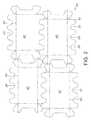
ここで図2を参照すると、トレイ12の形成が記載され得る。トレイ12は、典型的には、積層されているか、または積層されていない波形の紙または厚紙から、あるいは、当該技術分野において周知である他の様々な材料から形成された平面部材40から形成される。平面部材40は、複数のトレイ12を形成するために、複数の平坦なブランク42に切断されてよい。各ブランク42は次いで、個々のトレイ12を形成するために用いられる。4つのブランク42が、平面部材40から切断されて示されているが、任意の数のブランク42が、適切に大きさを整えられた平面部材40から切断されてもよいことは理解されてよい。さらに、ブランク42は連続的に、継続して切断されていてもよい。 Referring now to FIG. 2, the formation of the
各ブランク42は、波打ち形状の側壁24が対向する方向で外側に延びている図2において示される一般的な形状を有する。前述したように、側壁24上の各波打ち形状の実際の形状および大きさは様々であってよいが、ブランク42は、各側壁の壁部34が、隣接するブランク42の側壁の窪み32から形成されるように切断される。このように、壁部34および窪み32は相互にかみ合わせられている。 Each blank 42 has the general shape shown in FIG. 2 with the
例えば、側壁24における波打ち形状の形は、正弦波、矩形波、鋸歯状の波、および三角波を含んでよく、かつそれらに限定されない。さらに、上述のように、壁部34と窪み32とが相互に噛み合っていれば、波打ち形状の大きさは均一であっても、不均一であってもよい。これは廃材を著しく低減させる。なぜならば、窪み32を形成するために側壁24から切断された材料は廃材ではなくて、隣接するブランク42の壁部34を形成する材料だからである。 For example, the corrugated shape on the
以下、最後まで本明細書中で用いられるように、用語「波打ち形状」または「波打ち形状をした」は、規則的または不規則的の、任意の構成での山部および谷部を有する壁の延長部および窪み部によって形成された任意の構成を意味すると理解される。このような構成は、波形、キャスチレーション形(castillation)、ジグザグ形、クレスト形、谷形を含んでよく、かつそれらに限定されない。山部および谷部は、円形、矩形、台形等の様々な構成であってよい。このような形状の組合せが、単一の壁または複数の壁に沿って含まれてもよい。 Hereinafter, as used herein to the end, the term “wavy” or “wavy” refers to a wall having peaks and troughs in any configuration, regular or irregular. It is understood to mean any configuration formed by extensions and depressions. Such configurations may include, but are not limited to, corrugations, casting shapes, zigzag shapes, crest shapes, valley shapes. The peaks and valleys may have various configurations such as a circle, a rectangle, and a trapezoid. Combinations of such shapes may be included along a single wall or multiple walls.
これに関連して、隣り合って並んでいる隣接のブランク42は、1つのブランク42の長手方向の端壁部34が隣接するブランク42の窪み32から切断され得るように僅かにオフセットされている。類似する技術が、端壁26およびフランジ部27に対して、ブランク42を配置するように用いられる。 In this regard,
図2に示されるように、長手方向に隣接するブランク42の端壁26は、フランジ部27と同じように、隣りの隣接するブランク42の壁部34と相互に噛み合わされるか、または入れ子上にされる。この配置構成は、ブランク42の形成によって生成された廃品材料を著しく低減させ、その結果、トレイ32の製造コストを低減させる。 As shown in FIG. 2, the
いったんブランク42が、図2に示される方法で平面部材40から切断されると、各ブランク42は、折り目50に沿って折られて、図1に示されるトレイ12を形成してもよい。その後、各々個々のトレイ12は、パッケージ14の内容物をさらに保護するために、上包(図示されず)で包装されてもよい。 Once the
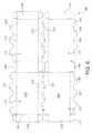
図3〜図5は、本発明のトレイのさらに好ましい実施形態を提供する。トレイ112は、対向する波打ち形状の第1の側壁123および第2の側壁125を含む。図3を参照すると、トレイ112の形成が、図1および図2に記載されたトレイ12の変形として記載され得る。トレイ112は、典型的には、積層されているか、または積層されていない波形の紙または厚紙から、あるいは、当該技術分野において周知である他の様々な材料から形成された平面部材40から形成される。平面部材140は、複数のトレイ112を形成するために、複数の平坦なブランク142に切断されてよい。 3-5 provide further preferred embodiments of the tray of the present invention. The
各ブランク142は、個々のトレイ112を形成するために用いられる。2つのブランク142が、平面部材140から切断されて示されているが、任意の数のブランク142が、適切に大きさを整えられた平面部材から切断されてもよいことは理解されてよい。さらに、ブランク142は連続的に、継続して切断されていてもよい。 Each blank 142 is used to form an
各ブランク142は、第1の側壁123および第2の側壁125が対向する方向で外側に延びている図3において示される一般的な形状を有する。側壁24上の各波打ち形状の実際の形状および大きさは様々であってよいが、ブランク142は、各側壁の延長壁部134が、隣接するブランク142の側壁の窪み132から形成されるように切断される。このように、延長壁部134および窪み132は相互にかみ合わせられている。 Each blank 142 has the general shape shown in FIG. 3 with the
例えば、前述の実施形態におけるように、側壁123および125における波打ち形状の形は、円形または正弦波、矩形波、鋸歯状の波、および三角波を含んでよく、かつそれらに限定されない。さらに、壁部134と窪み132とが相互に噛み合っていれば、波打ち形状の大きさは均一であっても、不均一であってもよい。これは廃材を著しく低減させる。なぜならば、第1の壁123から切断された材料は第2の壁125の窪み132を形成するために用いられ得るからである。それゆえ、第1の側壁123の延長壁部134を形成するために切断された材料は廃材ではなく、隣接するブランク142の窪み132を形成する材料であり、その逆もまた然りである。 For example, as in the previous embodiments, the corrugated shapes on the
これに関連して、隣り合って並んでいる隣接のブランク142は、1つのブランク142の長手方向の端壁部134が隣接するブランク142の窪み132から切断され得るように、長手方向に並んで置かれる。類似する技術が、端壁126およびフランジ部127に対して、ブランク142を配置するように用いられる。 In this regard, adjacent side-by-
上述のように、図1および図2のトレイの側壁24は、同じ配置構成および同じ数の窪み32(3つ)および延長壁部34(4つ)で構成される。図3に示される本実施形態においては、側壁123、125は、異なる配置構成および異なる数の窪み132および延長壁部134があるように構成される。図3に示される実施形態において、1つの側壁123は、3つの窪み132(C,D,E)および2つの延長壁部134(A、B)を含み、他方で、他の側壁125は、2つの窪み132(A、B)および3つの延長壁部134(C、D、E)を含む。このように、側壁のうちの1つのうちの窪みは、他の側壁の延長部と長手方向に並んで配置され、逆もまた然りである。このような配置構成の利点は、本明細書の以下でさらに十全に記載される。As described above, the
図3に示されるように、隣接するブランク142の側壁126は、長手方向に並んで置かれる。各ブランク142のフランジ部127もまた、隣接するブランク142のフランジ部127と、長手方向に並んで置かれる。この配置構成は、2つの対向する端壁126を有する各ブランク142を示す。2つの別個のブランク142は、別々に折り曲げられてもよく、次いで、互いに上に重ねられて、図4および図5に示されるように、カバートレイ112’および底トレイ112を生成する。 As shown in FIG. 3, the
図3の配置構成は、ブランク142の並び配置の結果、図2のブランク42と比較すると、ブランク142の形成によって生成される廃材の低減をさらに促す。それゆえ、図3のブランク142は、トレイ112の製造コストをさらに低減し得る。 The arrangement of FIG. 3 further promotes the reduction of waste material produced by the formation of the blank 142 as a result of the arrangement of the
図4は、切断および分離された後の、2つのブランク142の部分的な図を示す。図4はトレイ112を示し、このトレイ112は、2つの延長壁部134(A、B)および3つの窪み部132(C、D、E)を有する第1の側壁123と、そのトレイの対向する側に、3つの延長壁部134(C、D、E)および2つの窪み部132(A、B)を有する第2の側壁125とを有する。図4は、図2に示されるように長手方向にオフセットされる代わりに、この実施形態が、隣接するブランク142の構成が長手方向に並んで置かれることを可能にする方法をさらに示す。記載されるように、この配置構成は、ブランク142の形成によって生成される廃材をさらに低減する。 FIG. 4 shows a partial view of two
相互にかみ合わされた側壁123および125の配置構成はまた、図5に示されるように、さらなる有利な特徴を提供する。2つの同じように折られたトレイ112は、ベースまたは底トレイ112、および相互にかみ合わされた上側カバーまたは上側トレイ112’の役割を果たし得る。ブランク142は、図3に示される方法において平面部材140から切断され、この切断されたブランク142は、折り目150に沿って折られ、トレイ112を形成してよい。1つのブランク142が底トレイ112の役割を果たし得る一方で、他のブランク142’は逆にされて、カバートレイ112の役割を果たし得る。トレイ112および112’は、カバートレイ112’の側壁125’が底トレイ112の側壁123と並んで置かれるように配置され得る。対向する側壁(図示されず)も同様に置かれることが当然、当てはまり得る。この配置構成により、波打ち形状の側壁が、対向する波打ち形状の第1の側壁および第2の側壁123’、125、123、125’内で相互にかみ合わされるか、または入れ子にされることができる。 The interdigitated
本発明の本実施形態の設計は、1つのブランク142の製造が、底トレイ112およびカバートレイ112’の両方として用いられることを可能にする。このように、本発明は、本明細書中における図3から図5において提供された1つのトレイ112を用いて、製品を表示し、パッケージし、および輸送することを可能にする。 The design of this embodiment of the present invention allows the manufacture of one blank 142 to be used as both the
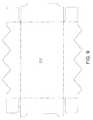
図6は、図3のブランク142に類似するブランク242の一例を提供するが、各ブランク242が、2つのトレイ112、112’を形成し、各トレイ112、112’が1つの別個の端壁126および共通の端壁144を有することが相違する。ブランク242は、ブランク242の半分が折られてカバートレイ112’を生成でき、そのブランク242のもう半分が折られて底トレイ112を生成するように構成される。 FIG. 6 provides an example of a blank 242 similar to the blank 142 of FIG. 3, but each blank 242 forms two
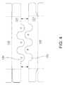
ブランクのさらに熟慮された他の構成は、波打ち形状の端部が、矩形の波打ち形状、三角の波打ち形状、台形の波打ち形状等の様々な大きさおよび形状の波打ち形状の領域を含んでよく、かつそれらに限定されない。さらに、波打ち形状の大きさは、両側の端部における波打ち形状が、中央の波打ち形状よりも小さくなるように(かつその逆になるように)変化してもよく、または不規則であってもよい。図7および図8はブランクの他の構成の例を提供する。 Other more contemplated configurations of the blank may include undulating regions of various sizes and shapes, such as a wavy end, a rectangular wavy shape, a triangular wavy shape, a trapezoidal wavy shape, And it is not limited to them. Further, the size of the undulating shape may vary such that the undulating shape at the ends on both sides is smaller (and vice versa) than the central undulating shape, or may be irregular Good. 7 and 8 provide other examples of blank configurations.
特に図7は矩形の波打ち形状を有するブランク342を示す。図8は、波打ち形状の端部に台形を有したブランク442を示し、図9は、側壁に沿ってジグザグのパターンの波打ち形状を有するブランク547を示す。図10は、側壁に沿って不規則なパターンの波打ち形状を有する側壁を有するブランク647を示す。図11は、1つの側壁に沿った波打ち形状を含む1つのみの側壁を有するブランク747を示す。反対側の側壁は波打ち形状を有さない。図11の側壁の波打ち形状は、任意の構成であってもよく、規則的でもよく、不規則でもよい。 In particular, FIG. 7 shows a blank 342 having a rectangular wavy shape. FIG. 8 shows a blank 442 having a trapezoid at the end of the corrugated shape, and FIG. 9 shows a blank 547 having a corrugated shape in a zigzag pattern along the sidewall. FIG. 10 shows a blank 647 having sidewalls having an irregular pattern of undulations along the sidewalls. FIG. 11 shows a blank 747 having only one sidewall including a corrugated shape along one sidewall. The opposite side wall does not have a corrugated shape. The corrugated shape of the side wall in FIG. 11 may be an arbitrary configuration, may be regular, or may be irregular.
(項目)
項目1.積み重ねられた複数の食品のパッケージを収容および分配するためのトレイであって、
底壁、ならびに、前記底壁から上方に延び開口上端を規定する、対向する前部の壁および後部の壁、および対向する側壁を有するハウジングを備え、
前記対向する前部の壁、後部の壁、または側壁の少なくとも1つは、間隔を置いて上方に開口した窪みによって規定される波打ち形状の上側範囲を含み、前記窪みは、前記対向する前部の壁、後部の壁、および側壁の少なくとも1つを介して、個々の積み重なったパッケージを手で掴むことができるように、前記積み重なったパッケージの下方に延びる開口部を有する、トレイ。
項目2.前記側壁は前記波打ち形状の上側範囲および前記窪みを含む、項目1に記載のトレイ。
項目3.前記側壁は第1の側壁および第2の側壁を含む、項目2に記載のトレイ。
項目4.前記第1の側壁は第1の数の窪みを含み、前記第2の側壁は第2の数の窪みを含む、項目3に記載のトレイ。
項目5.前記第1の数の窪みは前記第2の数の窪みと同じである、項目4に記載のトレイ。
項目6.前記第1の数の窪みは前記第2の窪みの数とは異なる、項目4に記載のトレイ。
項目7.前記第1の側壁の前記窪みは、前記第2の側壁の前記上方に延びる壁部と直接に対向する、項目6に記載のトレイ。
項目8.前記窪みは円形の底を有する、項目1〜7に記載のトレイ。
項目9.前記窪みは矩形の底を有する、項目1〜7に記載のトレイ。
項目10.前記窪みは台形の形状をした底を有する、項目1〜7に記載のトレイ。
項目11.前記波打ち形状の上側範囲は、前記各窪みの間の上方に延びる壁部を規定する、項目1〜7に記載のトレイ。
項目12.前記上方に延びる壁部は円形である、項目11に記載のトレイ。
項目13.前記上方に延びる壁部は矩形の形状である、項目11に記載のトレイ。
項目14.前記上方に延びる壁部は台形の形状である、項目11に記載のトレイ。
項目15.前記上方に延びる壁部はジグザグの形状である、項目11に記載のトレイ。
項目16.積み重なった複数の消費可能な製品のパッケージを収容および分配するためのトレイを形成するための方法であって、
平面部材を提供する工程と、
前記平面部材から、複数の隣接して配置される平坦なブランクを切断する工程であって、前記ブランクの各々は対向する長手方向の端を有し、端の各々は、交互になった延長部および窪みを規定する波打ち形状の構成を有し、1つの前記ブランクの前記延長部は前記隣接するブランクの前記窪みに形成される、工程と、
前記ブランクの各々を、底壁および対向する開口端を有するトレイ型のハウジングに折る工程であって、前記対向する長手方向の端が前記ハウジングの側壁を規定する、工程と、
を含む、方法。
項目17.前記切断する工程は、複数の前記ブランクを連続的に、継続して切断する工程をさらに含む、項目16に記載の方法。
項目18.前記切断する工程は、第1の側壁が第1の数の前記窪みを含むように、前記第1の側壁を切断する工程をさらに含む、項目16に記載の方法。
項目19.前記切断する工程は、第2の側壁が第2の数の前記窪みを含むように前記第2の側壁を切断することをさらに含み、前記第1の数の前記窪みは前記第2の数の前記窪みと同じである、項目18に記載の方法。
項目20.前記切断する工程は、第2の側壁が第2の数の前記窪みを含むように前記第2の側壁を切断する工程をさらに含み、前記第2の数の前記窪みは前記第1の数の前記窪みとは異なる、項目18に記載の方法。
項目21.前記折る工程は、対向する端壁を形成するために、前記ハウジングを折る工程を含む、項目16〜20に記載の方法。
項目22.カバーを生成するために別のトレイの上にトレイを配置する工程をさらに含み、各前記第1の側壁および各前記第2の側壁は、前記第1の側壁の各前記窪みが前記第2の側壁の各前記延長部に適合するように構成される、項目16〜20に記載の方法。
項目23.2つの隣接するブランクは、共通の壁によって折り畳み可能に連結されるように構成され、前記共通の壁は、前記2つの隣接するブランクの各々において、前記端壁の1つとなる、項目22に記載の方法。
項目24.前記切断する工程は、前記2つの隣接するブランクを切断する工程をさらに含み、前記共通の壁は、前記2つの隣接するブランクを共に保持する、項目23に記載の方法。
項目25.前記折る工程は、前記共通の端壁によって連結されたカバートレイおよび底トレイを用いて2つの取り付けられたトレイを形成するために、前記2つの隣接するブランクを折る工程をさらに含む、項目24に記載の方法。
項目26.前記平坦なブランクは、前記対向する側壁の前記波打ち形状が入れ子状、および長手方向に並んで置かれるように配置される、項目16〜20に記載の方法。
項目27.前記平坦なブランクは、前記対向する側壁の前記波打ち形状が入れ子状、および長手方向にオフセットされるように配置される、項目16〜20に記載の方法。
項目28.底トレイとなるように構成された第1のトレイと、
カバートレイとなるように構成された第2のトレイと
を備えるトレイアセンブリであって、
前記第1のトレイと前記第2のトレイとは同一に構成され、
前記第1のトレイおよび前記第2のトレイは各々、底壁、ならびに、前記底壁から上方に延び上側開口端を規定する、対向する前部の壁および後部の壁、および対向する側壁を備え、前記対向する側壁は、前記対向する側壁に交互になった延長部および窪みを規定する波打ち形状構成をさらに含み、
前記第2のトレイの前記窪みと並んで配置されかつ入れ子状となっている前記第1のトレイの前記延長部と、前記第2のトレイの前記延長部と並んで配置されかつ入れ子状となっている前記第1のトレイの前記窪みとを用いて、前記第2のトレイが前記第1のトレイの上部と適合するように構成されるように、前記第1のトレイおよび前記第2のトレイは長手方向に入れ子状となりかつ並んで配置されている、トレイアセンブリ。
項目29.前記側壁は第1の側壁および第2の側壁を含む、項目28に記載のトレイ。
項目30.前記第1の側壁は第1の数の窪みを含み、前記第2の側壁は第2の数の窪みを含む、項目29に記載のトレイ。
項目31.前記第1の数の窪みは前記第2の数の窪みと同じである、項目30に記載のトレイ。
項目32.前記第1の数の窪みは前記第2の数の窪みと異なる、項目30に記載のトレイ。
項目33.前記第1の側壁の前記窪みは、前記第2の側壁の前記上方に延びている壁部と直接に対向する、項目32に記載のトレイ。
項目34.トレイと少なくとも1つの食品のパッケージとの組み合わせであって、
前記食品のパッケージを収容するためのトレイハウジングであって、前記トレイハウジングは、底壁、ならびに、前記底壁から直立したハウジングの周囲を規定する一対の対向する長手方向の側壁および対向する横断方向の端壁を有するトレイハウジングと、
窪みと、
前記側壁の長さが延長している壁部との波打ち形状のパターンを含む少なくとも1つの前記側壁であって、前記窪みは前記側壁を介して前記パッケージへの手によるアクセスを可能にする、少なくとも1つの前記側壁とを備える、組み合わせ。
項目35.前記製品のパッケージは、上側範囲を有し、前記窪みは、前記トレイハウジング内に支持される前記製品パッケージの前記上側範囲の下方に延びている、項目34に記載の組み合わせ。
項目36.前記製品のパッケージは、1つの前記窪みに隣接して支持され、前記窪みは、前記トレイのハウジング内に支持される前記製品のパッケージの幅未満である前記製品のパッケージに隣接した幅を有する、項目34〜35に記載の組み合わせ。
項目37.前記波打ち形状のパターンは、前記側壁に沿って規則的である、項目34〜36に記載の組み合わせ。
項目38.前記側壁の各々の前記波打ち形状の部分は、1つの側壁の前記窪みが他の前記側壁の前記壁部と長手方向に並んで置かれるようにされている、項目34〜36に記載の組み合わせ。
項目39.各側壁の前記波打ち形状のパターンは、1つの側壁の前記窪みが他の前記側壁の窪みと長手方向に並んで置かれるようにされている、項目34〜36に記載の組み合わせ。
項目40.一対の前記トレイハウジングをさらに含み、前記対のトレイハウジングのうちの1つは、前記対のトレイハウジングのうちのもう1つと入れ子となることが可能であり、前記トレイハウジングの前記壁部は他の前記トレイハウジングの前記窪みと適合する、項目38に記載の組み合わせ。
項目41.前記トレイハウジングは平坦なブランクから形成される、項目34〜36に記載の組み合わせ。
項目42.前記対のトレイハウジングは隣接して入れ子状となった平坦なブランクから形成され、前記対のトレイハウジングの前記壁部は、他の前記トレイハウジングの前記窪みから形成される、項目41に記載の組み合わせ。
項目43.複数のパッケージングトレイを形成するための材料の平坦なシートであって、
前記シートに形成された第1のトレイのブランクであって、前記第1のブランクは、対向する長手方向の側壁および対向する横断方向の端壁を含む略矩形の構成を有し、前記側壁は、交互になった窪みと延長部とを規定する、前記側壁に沿った波打ち形状のパターンを有する、第1のトレイのブランクと、
前記シートに形成される第2のトレイのブランクであって、前記第2のブランクは、対向する長手方向の側壁および対向する横断方向の端壁を含む略矩形の構成を有し、前記側壁は、交互になった窪みと延長部とを規定する、前記側壁に沿った波打ち形状のパターンを有する、第2のトレイのブランクと、
を有し、
前記第1および第2の平坦なブランクは隣接して配置され、前記第1のトレイの前記側壁の前記延長部は、前記第2のトレイの前記側壁の前記窪みから形成される、材料の平坦なシート。
項目44.前記第1および第2のトレイのブランクの各々の前記側壁の各々は、前記側壁に沿って同数の窪みおよび延長部を有し、前記隣接する第1および第2のトレイのブランクは長手方向にジグザグ状である、項目43に記載の平坦なシート。
項目45.前記第1および第2のトレイのブランクの各々の前記側壁の各々は、前記側壁に沿って異なる数の窪みおよび延長部を有し、前記隣接する第1および第2のトレイのブランクは長手方向に並んで置かれる、項目43に記載の平坦なシート。
項目46.前記第1および第2のトレイのブランクのうちの1つは、少なくとも1つの食品のパッケージをトレイハウジング内に収容するためのトレイハウジングを規定するように構成される、項目45に記載の平坦なシート。
項目47.前記第1および第2のトレイのブランクのうちのもう1つは、前記1つのトレイハウジングと、覆うようにして入れ子状に係合するトレイカバーを規定するように構成される、項目46に記載の平坦なシート。(item)
Item 1. A tray for containing and dispensing a plurality of stacked food packages,
A housing having a bottom wall and opposing front and rear walls and opposing sidewalls extending upwardly from the bottom wall and defining an upper opening end;
At least one of the opposing front wall, rear wall, or side wall includes a corrugated upper range defined by spaced-apart upwardly opened depressions, the depressions being the opposed front parts A tray having an opening extending downwardly of the stacked packages so that the individual stacked packages can be grasped by hand through at least one of the wall, the rear wall, and the side walls.
Item 2. Item 4. The tray of item 1, wherein the side wall includes the wavy upper range and the depression.
Item 3. Item 3. The tray of item 2, wherein the side wall includes a first side wall and a second side wall.
Item 4. Item 4. The tray of item 3, wherein the first sidewall includes a first number of depressions and the second sidewall includes a second number of depressions.
Item 5. Item 5. The tray of item 4, wherein the first number of indentations is the same as the second number of indentations.
Item 6. Item 5. The tray of item 4, wherein the first number of depressions is different from the number of the second depressions.
Item 7. Item 7. The tray according to Item 6, wherein the recess of the first side wall directly faces the upwardly extending wall portion of the second side wall.
Item 8. Item 8. The tray of items 1-7, wherein the recess has a circular bottom.
Item 11. Item 8. The tray according to items 1-7, wherein the upper range of the corrugated shape defines an upwardly extending wall between the recesses.
Item 13.
Item 14.
Item 15.
Item 16. A method for forming a tray for receiving and dispensing a plurality of stacked packages of consumable products comprising:
Providing a planar member;
Cutting a plurality of adjacently disposed flat blanks from the planar member, each of the blanks having opposing longitudinal ends, each of the ends being an alternating extension And a corrugated configuration defining a depression, wherein the extension of one of the blanks is formed in the depression of the adjacent blank;
Folding each of the blanks into a tray-type housing having a bottom wall and opposing open ends, wherein the opposing longitudinal ends define sidewalls of the housing;
Including a method.
Item 17. The method according to item 16, wherein the cutting step further includes a step of continuously cutting the plurality of blanks continuously.
Item 18. 17. The method of item 16, wherein the cutting step further comprises cutting the first sidewall such that the first sidewall includes a first number of the depressions.
Item 19. The step of cutting further includes cutting the second sidewall such that a second sidewall includes a second number of the recesses, the first number of the recesses being the second number. 19. A method according to item 18, wherein the method is the same as the depression.
Item 21. 21. A method according to items 16 to 20, wherein the folding step includes the step of folding the housing to form opposing end walls.
Item 23. The two adjacent blanks are configured to be foldably connected by a common wall, the common wall being one of the end walls in each of the two adjacent blanks. 23. The method according to 22.
Item 25.
A tray assembly comprising a second tray configured to be a cover tray,
The first tray and the second tray are configured identically,
Each of the first tray and the second tray includes a bottom wall and opposing front and rear walls and opposing side walls that extend upward from the bottom wall and define an upper open end. The opposing sidewalls further include a corrugated configuration defining alternating extensions and depressions on the opposing sidewalls;
Nested and arranged side by side with the extension of the first tray and the extension of the second tray arranged side by side with the recess of the second tray The first tray and the second tray such that the second tray is configured to fit with an upper portion of the first tray using the recess of the first tray. Are tray assemblies nested in the longitudinal direction and arranged side by side.
Item 29. 29. A tray according to
Item 31. 31. A tray according to
Item 33. 33. A tray according to
A tray housing for containing said food package, said tray housing comprising a bottom wall and a pair of opposing longitudinal side walls and opposing transverse directions defining a perimeter of the housing upstanding from said bottom wall A tray housing having an end wall of
With a dimple,
At least one of the side walls comprising a corrugated pattern with a wall portion extending in length of the side wall, wherein the recess allows for manual access to the package through the side wall, at least A combination comprising one said side wall.
Item 35. 35. The combination of
Item 37. 37. A combination according to
Item 39. 37. The combination of items 34-36, wherein the corrugated pattern on each side wall is such that the depressions on one side wall are placed longitudinally alongside the depressions on the other side wall.
Item 41. 37. A combination according to
Item 43. A flat sheet of material to form a plurality of packaging trays,
A blank of a first tray formed on the sheet, the first blank having a generally rectangular configuration including opposing longitudinal side walls and opposing transverse end walls, wherein the side walls are A blank of the first tray having a corrugated pattern along the side walls defining alternating depressions and extensions;
A second tray blank formed on the sheet, the second blank having a generally rectangular configuration including opposing longitudinal side walls and opposing transverse end walls, the side walls comprising: A second tray blank having a corrugated pattern along the side walls defining alternating indentations and extensions;
Have
The first and second flat blanks are disposed adjacent to each other, and the extension of the side wall of the first tray is formed from the depression of the side wall of the second tray. Sheet.
Item 44. Each of the side walls of each of the first and second tray blanks has the same number of depressions and extensions along the side walls, and the adjacent first and second tray blanks are longitudinally 44. A flat sheet according to item 43, which is zigzag-shaped.
Item 45. Each of the side walls of each of the first and second tray blanks has a different number of depressions and extensions along the side walls, and the adjacent first and second tray blanks are longitudinal. 44. A flat sheet according to item 43, placed side by side.
Item 46. 46. The flat of item 45, wherein one of the first and second tray blanks is configured to define a tray housing for receiving at least one package of food within the tray housing. Sheet.
Item 47. 47. The item 46, wherein the other one of the first and second tray blanks is configured to define the one tray housing and a tray cover that nestingly engages the cover. Flat sheet.
上述に記載され、示される構造に対する種々の変形は当業者に明白であろう。したがって、特に本発明の開示される範囲は添付の特許請求の範囲に記載される。 Various modifications to the structures described and shown above will be apparent to those skilled in the art. Accordingly, the particularly disclosed scope of the invention is set forth in the appended claims.
112 底トレイ
112’ カバートレイ
123 第1の側壁
125 第2の側壁
127 フランジ部
132 窪み
144 端壁
150 折り目
242 ブランク112 Bottom tray 112 '
Claims (15)
Translated fromJapaneseカバートレイとなるように構成された第2のトレイと
を備えるトレイアセンブリであって、
前記第1のトレイと前記第2のトレイとは同一に構成され、
前記第1のトレイおよび前記第2のトレイは各々、底壁、ならびに、前記底壁から上方に延び上側開口端を規定する、対向する前部の壁および後部の壁、および対向する側壁を備え、前記対向する側壁は、前記対向する側壁に交互になった延長部および窪みを規定する波打ち形状構成をさらに含み、
前記第2のトレイの前記窪みと並んで配置されかつ入れ子状となっている前記第1のトレイの前記延長部と、前記第2のトレイの前記延長部と並んで配置されかつ入れ子状となっている前記第1のトレイの前記窪みとを用いて、前記第2のトレイが前記第1のトレイの上部と適合するように構成されるように、前記第1のトレイおよび前記第2のトレイは長手方向に入れ子状となりかつ並んで配置されている、トレイアセンブリ。A first tray configured to be a bottom tray;
A tray assembly comprising a second tray configured to be a cover tray,
The first tray and the second tray are configured identically,
Each of the first tray and the second tray includes a bottom wall and opposing front and rear walls and opposing side walls that extend upward from the bottom wall and define an upper open end. The opposing sidewalls further include a corrugated configuration defining alternating extensions and depressions on the opposing sidewalls;
Nested and arranged side by side with the extension of the first tray and the extension of the second tray arranged side by side with the recess of the second tray The first tray and the second tray such that the second tray is configured to fit with an upper portion of the first tray using the recess of the first tray. Are tray assemblies nested in the longitudinal direction and arranged side by side.
前記食品のパッケージを収容するためのトレイハウジングであって、前記トレイハウジングは、底壁、ならびに、前記底壁から直立したハウジングの周囲を規定する一対の対向する長手方向の側壁および対向する横断方向の端壁を有するトレイハウジングと、
窪みと、
前記側壁の長さが延長している壁部との波打ち形状のパターンを含む少なくとも1つの前記側壁であって、前記窪みは前記側壁を介して前記パッケージへの手によるアクセスを可能にする、少なくとも1つの前記側壁とを備える、組み合わせ。A combination of a tray and at least one food package,
A tray housing for containing said food package, said tray housing comprising a bottom wall and a pair of opposing longitudinal side walls and opposing transverse directions defining a perimeter of the housing upstanding from said bottom wall A tray housing having an end wall of
With a dimple,
At least one of the side walls comprising a corrugated pattern with a wall portion extending in length of the side wall, wherein the recess allows for manual access to the package through the side wall, at least A combination comprising one said side wall.
Applications Claiming Priority (4)
| Application Number | Priority Date | Filing Date | Title |
|---|---|---|---|
| US5307008P | 2008-05-14 | 2008-05-14 | |
| US61/053,070 | 2008-05-14 | ||
| US11680508P | 2008-11-21 | 2008-11-21 | |
| US61/116,805 | 2008-11-21 |
Related Parent Applications (1)
| Application Number | Title | Priority Date | Filing Date |
|---|---|---|---|
| JP2011509635ADivisionJP2011520715A (en) | 2008-05-14 | 2009-05-13 | Package and display tray formed from concatenated blanks |
Publications (1)
| Publication Number | Publication Date |
|---|---|
| JP2014101150Atrue JP2014101150A (en) | 2014-06-05 |
Family
ID=40908538
Family Applications (2)
| Application Number | Title | Priority Date | Filing Date |
|---|---|---|---|
| JP2011509635APendingJP2011520715A (en) | 2008-05-14 | 2009-05-13 | Package and display tray formed from concatenated blanks |
| JP2014021059APendingJP2014101150A (en) | 2008-05-14 | 2014-02-06 | Packaging and display tray formed from interlocked blanks |
Family Applications Before (1)
| Application Number | Title | Priority Date | Filing Date |
|---|---|---|---|
| JP2011509635APendingJP2011520715A (en) | 2008-05-14 | 2009-05-13 | Package and display tray formed from concatenated blanks |
Country Status (12)
| Country | Link |
|---|---|
| US (1) | US20090283581A1 (en) |
| EP (1) | EP2282948B1 (en) |
| JP (2) | JP2011520715A (en) |
| CN (1) | CN102026882B (en) |
| AT (1) | ATE539971T1 (en) |
| AU (1) | AU2009246428B2 (en) |
| CA (1) | CA2723755C (en) |
| ES (1) | ES2378445T3 (en) |
| MX (1) | MX2010012493A (en) |
| PL (1) | PL2282948T3 (en) |
| WO (1) | WO2009140346A1 (en) |
| ZA (1) | ZA200903291B (en) |
Cited By (1)
| Publication number | Priority date | Publication date | Assignee | Title |
|---|---|---|---|---|
| JP2019513644A (en)* | 2016-04-15 | 2019-05-30 | エコ. ロジック ブランズ インコーポレイテッド | Interconnection means for multipart containers |
Families Citing this family (10)
| Publication number | Priority date | Publication date | Assignee | Title |
|---|---|---|---|---|
| US20150375889A1 (en)* | 2010-09-15 | 2015-12-31 | Robert David Brockman | Under Sink Leak Protector Tray and Associated Method |
| GB201205243D0 (en) | 2012-03-26 | 2012-05-09 | Kraft Foods R & D Inc | Packaging and method of opening |
| GB2511560B (en) | 2013-03-07 | 2018-11-14 | Mondelez Uk R&D Ltd | Improved Packaging and Method of Forming Packaging |
| GB2511559B (en) | 2013-03-07 | 2018-11-14 | Mondelez Uk R&D Ltd | Improved Packaging and Method of Forming Packaging |
| DE102013110764A1 (en)* | 2013-09-27 | 2015-04-02 | Van Genechten Packaging N.V. | carton blank |
| ES2718388T3 (en) | 2015-05-20 | 2019-07-01 | Sika Tech Ag | Application of a randomly deposited material for road construction with improved adhesive properties |
| CN112224594B (en)* | 2020-10-26 | 2022-08-05 | 上海八彦图信息科技有限公司 | Ginseng honoured guest certificate sorting device |
| WO2022250713A1 (en)* | 2021-05-25 | 2022-12-01 | Citadel Casing Ltd | Interlocking case inserts |
| USD1043370S1 (en) | 2021-06-22 | 2024-09-24 | Citadel Casing Ltd | Packaging |
| DE102023131101A1 (en) | 2023-11-09 | 2025-05-15 | Amecke Markenvertrieb GmbH & Co. KG | Outer packaging for beverage cartons |
Citations (5)
| Publication number | Priority date | Publication date | Assignee | Title |
|---|---|---|---|---|
| US3521748A (en)* | 1968-06-27 | 1970-07-28 | Inland Container Corp | Adjustable depth carton |
| US5060851A (en)* | 1988-09-26 | 1991-10-29 | Macmillan Bloedel Containers | Interlocking container for carry-out food products |
| US6029803A (en)* | 1999-01-14 | 2000-02-29 | Ovadia Corp. | Display and storage box with interlocking, friction fitting halves |
| WO2006084923A1 (en)* | 2005-02-08 | 2006-08-17 | Kappa Iberoamericana, S.A. | Improvements to cardboard boxes for perishable goods and similar |
| US7316319B2 (en)* | 2003-12-23 | 2008-01-08 | Thomas West | Lift van system |
Family Cites Families (16)
| Publication number | Priority date | Publication date | Assignee | Title |
|---|---|---|---|---|
| US2027747A (en)* | 1934-10-30 | 1936-01-14 | Hinde & Dauch Paper Co | Joined structure |
| US2888132A (en)* | 1955-08-12 | 1959-05-26 | Waldorf Paper Prod Co | Divisible carton |
| GB1392286A (en)* | 1971-04-05 | 1975-04-30 | Unilever Ltd | Blanks for cartons |
| FR2308553A1 (en)* | 1975-04-23 | 1976-11-19 | Sauterot Drac | Mfg. punnets for cooked foods - by cutting sheet to form blanks having wavy edges formed by single cuts between blanks |
| JPS5346943U (en)* | 1976-09-27 | 1978-04-21 | ||
| JPS5758019U (en)* | 1980-09-19 | 1982-04-06 | ||
| US4746010A (en)* | 1986-06-30 | 1988-05-24 | Stephen Fournier | Box convertible to food item tray |
| FR2676035A1 (en)* | 1991-04-30 | 1992-11-06 | Cartonnerie Moderne Ets Moulin | Cut-out for making a folding packaging box and box thus obtained |
| US5154292A (en)* | 1991-12-02 | 1992-10-13 | Bartucca Frank A | Sports card sleeve box |
| US5913424A (en)* | 1993-07-14 | 1999-06-22 | Tulip Corporation | Storage and display trays |
| US5839650A (en)* | 1997-03-07 | 1998-11-24 | Triangle Container Corporation | Stackable container |
| US6158653A (en)* | 1999-02-10 | 2000-12-12 | Allen Kanter | Container having improved stacking strength |
| USD469255S1 (en)* | 2001-05-08 | 2003-01-28 | Roy Hammett | Beverage tray |
| GB0202869D0 (en)* | 2002-02-07 | 2002-03-27 | Mead Corp | Carton with overlapped base panels and blank therefor |
| US20050121348A1 (en)* | 2003-12-09 | 2005-06-09 | Clare Timothy P. | Package insert and stackable package for articles |
| GB2437514A (en)* | 2006-04-26 | 2007-10-31 | Sca Packaging Ltd | Display tray for supporting sachets |
- 2009
- 2009-05-13WOPCT/US2009/043729patent/WO2009140346A1/enactiveApplication Filing
- 2009-05-13AUAU2009246428Apatent/AU2009246428B2/ennot_activeCeased
- 2009-05-13USUS12/465,021patent/US20090283581A1/ennot_activeAbandoned
- 2009-05-13EPEP09747430Apatent/EP2282948B1/ennot_activeNot-in-force
- 2009-05-13CNCN200980117476.0Apatent/CN102026882B/ennot_activeExpired - Fee Related
- 2009-05-13PLPL09747430Tpatent/PL2282948T3/enunknown
- 2009-05-13ZAZA2009/03291Apatent/ZA200903291B/enunknown
- 2009-05-13JPJP2011509635Apatent/JP2011520715A/enactivePending
- 2009-05-13CACA2723755Apatent/CA2723755C/ennot_activeExpired - Fee Related
- 2009-05-13ESES09747430Tpatent/ES2378445T3/enactiveActive
- 2009-05-13MXMX2010012493Apatent/MX2010012493A/enactiveIP Right Grant
- 2009-05-13ATAT09747430Tpatent/ATE539971T1/enactive
- 2014
- 2014-02-06JPJP2014021059Apatent/JP2014101150A/enactivePending
Patent Citations (5)
| Publication number | Priority date | Publication date | Assignee | Title |
|---|---|---|---|---|
| US3521748A (en)* | 1968-06-27 | 1970-07-28 | Inland Container Corp | Adjustable depth carton |
| US5060851A (en)* | 1988-09-26 | 1991-10-29 | Macmillan Bloedel Containers | Interlocking container for carry-out food products |
| US6029803A (en)* | 1999-01-14 | 2000-02-29 | Ovadia Corp. | Display and storage box with interlocking, friction fitting halves |
| US7316319B2 (en)* | 2003-12-23 | 2008-01-08 | Thomas West | Lift van system |
| WO2006084923A1 (en)* | 2005-02-08 | 2006-08-17 | Kappa Iberoamericana, S.A. | Improvements to cardboard boxes for perishable goods and similar |
Cited By (6)
| Publication number | Priority date | Publication date | Assignee | Title |
|---|---|---|---|---|
| JP2019513644A (en)* | 2016-04-15 | 2019-05-30 | エコ. ロジック ブランズ インコーポレイテッド | Interconnection means for multipart containers |
| JP7012024B2 (en) | 2016-04-15 | 2022-01-27 | エコ. ロジック ブランズ インコーポレイテッド | Interconnection means for multi-part containers |
| JP2022027849A (en)* | 2016-04-15 | 2022-02-14 | エコ. ロジック ブランズ インコーポレイテッド | Interconnection means for multi parts container |
| JP7321238B2 (en) | 2016-04-15 | 2023-08-04 | エコ. ロジック ブランズ インコーポレイテッド | Interconnection means for multi-part containers |
| JP2023129620A (en)* | 2016-04-15 | 2023-09-14 | エコ. ロジック ブランズ インコーポレイテッド | Interconnection means for multi parts container |
| US12358681B2 (en) | 2016-04-15 | 2025-07-15 | Eco.Logic Brands Inc. | Inter-connecting means for multi-part container |
Also Published As
| Publication number | Publication date |
|---|---|
| CN102026882A (en) | 2011-04-20 |
| AU2009246428B2 (en) | 2012-08-23 |
| EP2282948B1 (en) | 2012-01-04 |
| CA2723755A1 (en) | 2009-11-19 |
| ES2378445T3 (en) | 2012-04-12 |
| WO2009140346A1 (en) | 2009-11-19 |
| CA2723755C (en) | 2013-12-31 |
| EP2282948A1 (en) | 2011-02-16 |
| MX2010012493A (en) | 2010-12-17 |
| JP2011520715A (en) | 2011-07-21 |
| US20090283581A1 (en) | 2009-11-19 |
| CN102026882B (en) | 2014-01-15 |
| ATE539971T1 (en) | 2012-01-15 |
| PL2282948T3 (en) | 2012-10-31 |
| AU2009246428A1 (en) | 2009-11-19 |
| ZA200903291B (en) | 2009-12-30 |
Similar Documents
| Publication | Publication Date | Title |
|---|---|---|
| JP2014101150A (en) | Packaging and display tray formed from interlocked blanks | |
| EP1934102B1 (en) | Bundle pack | |
| US8720689B2 (en) | Multi-tiered cupcake container | |
| US9078533B2 (en) | Display tray for displaying a plurality of containers | |
| AU2012258335B2 (en) | Packaging and display tray formed from interlocked blanks | |
| JPH10194330A (en) | Holding tool for container | |
| JPWO2017018531A1 (en) | container | |
| JP5824975B2 (en) | Paper box with simple partition | |
| JP2013107675A (en) | Packaging protective material | |
| JP4062378B2 (en) | Subdivision tray | |
| JP3244892U (en) | Packaging cover for egg cartons | |
| KR20110127781A (en) | Canned food packaging boxes and their supporting packages | |
| US20090223978A1 (en) | Display stand with disposable serving containers | |
| JP2005153914A (en) | Joining multipack | |
| US20120305440A1 (en) | Layered product stacking structure | |
| RU89501U1 (en) | PACKING AND TRAY | |
| JP2011116432A (en) | Pack for bunched-up container | |
| JPH0630081U (en) | Hygiene product packaging bag | |
| US20110192809A1 (en) | Structure for the placement, display and packing of merchandise | |
| JP2004210336A (en) | Packaging box | |
| JP2004210337A (en) | Packaging box |
Legal Events
| Date | Code | Title | Description |
|---|---|---|---|
| A621 | Written request for application examination | Free format text:JAPANESE INTERMEDIATE CODE: A621 Effective date:20140307 | |
| A131 | Notification of reasons for refusal | Free format text:JAPANESE INTERMEDIATE CODE: A131 Effective date:20150526 | |
| A02 | Decision of refusal | Free format text:JAPANESE INTERMEDIATE CODE: A02 Effective date:20151110 |