JP2014097224A - Dialysis unit and method for measuring access recirculation rate - Google Patents
Dialysis unit and method for measuring access recirculation rateDownload PDFInfo
- Publication number
- JP2014097224A JP2014097224AJP2012251210AJP2012251210AJP2014097224AJP 2014097224 AJP2014097224 AJP 2014097224AJP 2012251210 AJP2012251210 AJP 2012251210AJP 2012251210 AJP2012251210 AJP 2012251210AJP 2014097224 AJP2014097224 AJP 2014097224A
- Authority
- JP
- Japan
- Prior art keywords
- blood
- dialysate
- line
- downstream
- sodium chloride
- Prior art date
- Legal status (The legal status is an assumption and is not a legal conclusion. Google has not performed a legal analysis and makes no representation as to the accuracy of the status listed.)
- Pending
Links
- 238000000502dialysisMethods0.000titleclaimsabstractdescription55
- 238000000034methodMethods0.000titleclaimsabstractdescription19
- 239000008280bloodSubstances0.000claimsabstractdescription185
- 210000004369bloodAnatomy0.000claimsabstractdescription185
- FAPWRFPIFSIZLT-UHFFFAOYSA-MSodium chlorideChemical compound[Na+].[Cl-]FAPWRFPIFSIZLT-UHFFFAOYSA-M0.000claimsabstractdescription174
- 239000011780sodium chlorideSubstances0.000claimsabstractdescription87
- 238000011144upstream manufacturingMethods0.000claimsabstractdescription64
- 238000000691measurement methodMethods0.000claimsdescription5
- 239000000243solutionSubstances0.000abstractdescription53
- 238000005259measurementMethods0.000abstractdescription9
- 239000000385dialysis solutionSubstances0.000abstract9
- 230000017531blood circulationEffects0.000description11
- 239000012510hollow fiberSubstances0.000description10
- 238000010586diagramMethods0.000description9
- 238000010790dilutionMethods0.000description9
- 239000012895dilutionSubstances0.000description9
- 210000003462veinAnatomy0.000description7
- 238000001631haemodialysisMethods0.000description5
- 230000000322hemodialysisEffects0.000description5
- 239000002504physiological saline solutionSubstances0.000description5
- XSQUKJJJFZCRTK-UHFFFAOYSA-NUreaChemical compoundNC(N)=OXSQUKJJJFZCRTK-UHFFFAOYSA-N0.000description4
- 239000004202carbamideSubstances0.000description4
- 230000004087circulationEffects0.000description4
- 210000001367arteryAnatomy0.000description3
- XLYOFNOQVPJJNP-UHFFFAOYSA-NwaterSubstancesOXLYOFNOQVPJJNP-UHFFFAOYSA-N0.000description3
- 238000007796conventional methodMethods0.000description2
- 238000012937correctionMethods0.000description2
- 238000012546transferMethods0.000description2
- VEXZGXHMUGYJMC-UHFFFAOYSA-MChloride anionChemical compound[Cl-]VEXZGXHMUGYJMC-UHFFFAOYSA-M0.000description1
- DGAQECJNVWCQMB-PUAWFVPOSA-MIlexoside XXIXChemical compoundC[C@@H]1CC[C@@]2(CC[C@@]3(C(=CC[C@H]4[C@]3(CC[C@@H]5[C@@]4(CC[C@@H](C5(C)C)OS(=O)(=O)[O-])C)C)[C@@H]2[C@]1(C)O)C)C(=O)O[C@H]6[C@@H]([C@H]([C@@H]([C@H](O6)CO)O)O)O.[Na+]DGAQECJNVWCQMB-PUAWFVPOSA-M0.000description1
- 208000031481Pathologic ConstrictionDiseases0.000description1
- 239000003814drugSubstances0.000description1
- 229940079593drugDrugs0.000description1
- 230000000694effectsEffects0.000description1
- 238000002474experimental methodMethods0.000description1
- 238000001914filtrationMethods0.000description1
- 230000010354integrationEffects0.000description1
- 239000007788liquidSubstances0.000description1
- 238000012986modificationMethods0.000description1
- 230000004048modificationEffects0.000description1
- 238000012544monitoring processMethods0.000description1
- 229910052708sodiumInorganic materials0.000description1
- 239000011734sodiumSubstances0.000description1
- 208000037804stenosisDiseases0.000description1
- 230000036262stenosisEffects0.000description1
- 239000000126substanceSubstances0.000description1
- 238000013519translationMethods0.000description1
Images


Classifications
- A—HUMAN NECESSITIES
- A61—MEDICAL OR VETERINARY SCIENCE; HYGIENE
- A61M—DEVICES FOR INTRODUCING MEDIA INTO, OR ONTO, THE BODY; DEVICES FOR TRANSDUCING BODY MEDIA OR FOR TAKING MEDIA FROM THE BODY; DEVICES FOR PRODUCING OR ENDING SLEEP OR STUPOR
- A61M1/00—Suction or pumping devices for medical purposes; Devices for carrying-off, for treatment of, or for carrying-over, body-liquids; Drainage systems
- A61M1/34—Filtering material out of the blood by passing it through a membrane, i.e. hemofiltration or diafiltration
- A61M1/342—Adding solutions to the blood, e.g. substitution solutions
- A61M1/3424—Substitution fluid path
- A61M1/3431—Substitution fluid path upstream of the filter
- A61M1/3434—Substitution fluid path upstream of the filter with pre-dilution and post-dilution
- A—HUMAN NECESSITIES
- A61—MEDICAL OR VETERINARY SCIENCE; HYGIENE
- A61M—DEVICES FOR INTRODUCING MEDIA INTO, OR ONTO, THE BODY; DEVICES FOR TRANSDUCING BODY MEDIA OR FOR TAKING MEDIA FROM THE BODY; DEVICES FOR PRODUCING OR ENDING SLEEP OR STUPOR
- A61M1/00—Suction or pumping devices for medical purposes; Devices for carrying-off, for treatment of, or for carrying-over, body-liquids; Drainage systems
- A61M1/34—Filtering material out of the blood by passing it through a membrane, i.e. hemofiltration or diafiltration
- A61M1/342—Adding solutions to the blood, e.g. substitution solutions
- A61M1/3424—Substitution fluid path
- A61M1/3437—Substitution fluid path downstream of the filter, e.g. post-dilution with filtrate
- A—HUMAN NECESSITIES
- A61—MEDICAL OR VETERINARY SCIENCE; HYGIENE
- A61M—DEVICES FOR INTRODUCING MEDIA INTO, OR ONTO, THE BODY; DEVICES FOR TRANSDUCING BODY MEDIA OR FOR TAKING MEDIA FROM THE BODY; DEVICES FOR PRODUCING OR ENDING SLEEP OR STUPOR
- A61M1/00—Suction or pumping devices for medical purposes; Devices for carrying-off, for treatment of, or for carrying-over, body-liquids; Drainage systems
- A61M1/36—Other treatment of blood in a by-pass of the natural circulatory system, e.g. temperature adaptation, irradiation ; Extra-corporeal blood circuits
- A61M1/3607—Regulation parameters
- A61M1/3609—Physical characteristics of the blood, e.g. haematocrit, urea
- A—HUMAN NECESSITIES
- A61—MEDICAL OR VETERINARY SCIENCE; HYGIENE
- A61M—DEVICES FOR INTRODUCING MEDIA INTO, OR ONTO, THE BODY; DEVICES FOR TRANSDUCING BODY MEDIA OR FOR TAKING MEDIA FROM THE BODY; DEVICES FOR PRODUCING OR ENDING SLEEP OR STUPOR
- A61M1/00—Suction or pumping devices for medical purposes; Devices for carrying-off, for treatment of, or for carrying-over, body-liquids; Drainage systems
- A61M1/36—Other treatment of blood in a by-pass of the natural circulatory system, e.g. temperature adaptation, irradiation ; Extra-corporeal blood circuits
- A61M1/3621—Extra-corporeal blood circuits
- A61M1/3653—Interfaces between patient blood circulation and extra-corporal blood circuit
- A61M1/3656—Monitoring patency or flow at connection sites; Detecting disconnections
- A61M1/3658—Indicating the amount of purified blood recirculating in the fistula or shunt
- A—HUMAN NECESSITIES
- A61—MEDICAL OR VETERINARY SCIENCE; HYGIENE
- A61M—DEVICES FOR INTRODUCING MEDIA INTO, OR ONTO, THE BODY; DEVICES FOR TRANSDUCING BODY MEDIA OR FOR TAKING MEDIA FROM THE BODY; DEVICES FOR PRODUCING OR ENDING SLEEP OR STUPOR
- A61M2205/00—General characteristics of the apparatus
- A61M2205/33—Controlling, regulating or measuring
- A61M2205/3375—Acoustical, e.g. ultrasonic, measuring means
Landscapes
- Health & Medical Sciences (AREA)
- Heart & Thoracic Surgery (AREA)
- Vascular Medicine (AREA)
- Biomedical Technology (AREA)
- Engineering & Computer Science (AREA)
- Anesthesiology (AREA)
- Hematology (AREA)
- Life Sciences & Earth Sciences (AREA)
- Animal Behavior & Ethology (AREA)
- General Health & Medical Sciences (AREA)
- Public Health (AREA)
- Veterinary Medicine (AREA)
- Cardiology (AREA)
- External Artificial Organs (AREA)
Abstract
Description
Translated fromJapaneseこの発明は、血液透析、血液濾過、血液交換等の体外循環回路において、再循環測定が可能な透析ユニットおよびアクセス再循環率の測定方法に関する。 The present invention relates to a dialysis unit capable of measuring recirculation in an extracorporeal circuit such as hemodialysis, blood filtration, and blood exchange, and a method for measuring an access recirculation rate.
図7に、血液透析に用いられる体外循環回路2000を示す。この体外循環回路2000は、透析ユニット200と透析装置600とを有する。 FIG. 7 shows an
透析ユニット200は、血液透析器30、上流側血液ラインBC1および下流側血液ラインBC2を有する血液回路BCと、上流側透析液ラインDC1および下流側透析液ラインDC2を有する透析液回路DCとを備える。 The
血液透析器30は、血液入口BF1および血液出口BF2と、透析液入口DF1および透析液出口DF2とを有する。血液透析器30の内部には、中空糸フィルタが装着されている。血液透析器30の内部においては、中空糸フィルタの内部を血液が流れ、中空糸フィルタの外部を血液の流れと反対方向に透析液が流れる。この中空糸フィルタを用いて血液と透析液との間で透析が行なわれる。 The
血液透析器30の血液入口BF1には、上流側血液ラインBC1の一端が連結される。上流側血液ラインBC1の他端には動脈用穿刺針1が設けられている。動脈用穿刺針1は、後述する患者P1の動静脈シャントの非透析時における血流において下流側の部位に穿刺される。 One end of the upstream blood line BC1 is connected to the blood inlet BF1 of the
血液透析器30の血液出口BF2には、下流側血液ラインBC2の一端が連結される。下流側血液ラインBC2の他端には静脈用穿刺針2が設けられている。静脈用穿刺針2は、後述する患者P1の静脈に穿刺される。 One end of the downstream blood line BC2 is connected to the blood outlet BF2 of the
血液透析器30の透析液入口DF1には、上流側透析液ラインDC1の一端が連結される。上流側透析液ラインDC1の他端は、透析装置600に連結され、新鮮な透析液が導入される。 One end of the upstream dialysate line DC1 is connected to the dialysate inlet DF1 of the
血液透析器30の透析液出口DF2には、下流側透析液ラインDC2の一端が連結される。下流側透析液ラインDC2の他端は、透析装置600に連結され、使用後の透析液が排出される。 One end of the downstream dialysate line DC2 is connected to the dialysate outlet DF2 of the
図8を参照して、血液透析においては、患者P1には、動脈A10と静脈V10とを連結する動静脈シャントST10が施術される。上記したように、動脈用穿刺針1が非透析時における血流において上流側の動静脈シャントの部位ST10に穿刺され、静脈用穿刺針2が非透析時における血流において下流側の動静脈シャントの部位V10に穿刺される。 Referring to FIG. 8, in hemodialysis, arteriovenous shunt ST10 that connects artery A10 and vein V10 is performed on patient P1. As described above, the
動脈用穿刺針1から上流側血液ラインBC1に導入された血液は、血液透析器30において透析される。血液透析器30において透析された血液は、下流側血液ラインBC2から静脈用穿刺針2を通じて患者P1の非透析時における血流において下流側の動静脈シャントの部位V10に戻される。 The blood introduced from the
上記体外循環回路2000においては、動静脈シャントST10におけるアクセス再循環の発生が問題となる。図8を参照して、本来であれば、静脈シャントの部位V10に戻された透析後の血液は、患者の全身に運ばれることになる。 In the
しかし、動静脈シャントに狭窄が生じているために、動静脈シャントを流通する血流が減少している場合には、動静脈シャントの部位V10に戻された透析後の血液の一部が、図8のX1に示すように動静脈シャントST10を逆流し、動脈用穿刺針1から上流側血液ラインBC1に再び導入されることがある。このように、透析された血液が全身を巡らずに、動静脈シャントST10を逆流し、上流側血液ラインBC1に導入されることをアクセス再循環という。 However, when the blood flow flowing through the arteriovenous shunt is reduced due to stenosis in the arteriovenous shunt, a part of the blood after dialysis returned to the site V10 of the arteriovenous shunt is As shown by X1 in FIG. 8, the arteriovenous shunt ST10 may flow backward and may be reintroduced from the
図7を再び参照して、このアクセス再循環の発生を検出するために、体外循環回路2000においては、以下に示す方法が用いられている。まず、上流側血液ラインBC1に上流側超音波センサ80を設け、下流側血液ラインBC2に下流側超音波センサ90を設ける。下流側血液ラインBC2に設けられたドリップチャンバ210から、塩化ナトリウム濃度が約0.9%の生理食塩水を10ml導入する。 Referring again to FIG. 7, in order to detect the occurrence of this access recirculation,
その後、下流側超音波センサ90により下流側血液ラインBC2を通過する血液の希釈率を測定し、また、上流側超音波センサ80により上流側血液ラインBC1を通過する血液の希釈率を測定する。 Thereafter, the dilution rate of blood passing through the downstream blood line BC2 is measured by the downstream
アクセス再循環が発生していない場合には、図9に示すように、下流側血液ラインBC2を通過する血液には、下流側超音波センサ90により血液の希釈が検出される。上流側血液ラインBC1を通過する血液は、上流側超音波センサ80によりの血液の希釈は測定されない。 When access recirculation has not occurred, dilution of blood is detected by the downstream
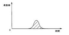
一方、アクセス再循環が発生している場合には、図9に示すように、下流側血液ラインBC2を通過する血液には、下流側超音波センサ90により血液の希釈が検出され、さらに、図10に示すように、上流側血液ラインBC1を通過する血液にも、上流側超音波センサ80により血液の希釈が検出される。なお、図9および図10において、横軸は時間を示し、縦軸は血液の希釈率を示す。 On the other hand, when access recirculation has occurred, as shown in FIG. 9, dilution of blood is detected by the downstream
このように、超音波センサを用いたアクセス再循環の発生を検出する方法は、たとえば、特表平10−505766号公報(特許文献1)に開示されている。 Thus, a method for detecting the occurrence of access recirculation using an ultrasonic sensor is disclosed in, for example, Japanese translation of PCT publication No. 10-505766 (Patent Document 1).
超音波センサは、血液中の水分量の変化を、超音波を用いて検出することから、外気温度、血液温度等の環境に応じて測定精度に変化が生じる。そのため、超音波を用いて測定する際には、その都度、測定結果に対して環境に応じた補正(ゼロ点調整/ゼロ点補正)を行なう必要がある。 Since the ultrasonic sensor detects a change in the amount of water in the blood using ultrasonic waves, the measurement accuracy varies depending on the environment such as the outside air temperature and the blood temperature. Therefore, when measuring using ultrasonic waves, it is necessary to perform correction (zero point adjustment / zero point correction) according to the environment on the measurement result each time.
また、超音波センサを用いた血液中の水分量の測定は、血液ラインを構成する管壁を介して行なわれるため、血液中の水分量の変化の測定精度の向上には限界がある。 In addition, since the measurement of the amount of water in the blood using an ultrasonic sensor is performed through the tube wall constituting the blood line, there is a limit to improving the measurement accuracy of the change in the amount of water in the blood.
したがって、超音波センサを用いた場合には、正確なアクセス再循環率(アクセス再循環が行なわれている割合)を測定することはできない。 Therefore, when an ultrasonic sensor is used, an accurate access recirculation rate (a rate at which access recirculation is performed) cannot be measured.
また、超音波センサを用いてアクセス再循環の発生を検出する場合には、超音波センサが高価であるため、治療コストが上昇するという問題も生じる。 In addition, when the occurrence of access recirculation is detected using an ultrasonic sensor, the ultrasonic sensor is expensive, which causes a problem that treatment costs increase.
この発明は上記課題に鑑みてなされたもので、この発明の目的は、測定環境に影響を受けることなく、アクセス再循環の有無を検出し、更に、アクセス再循環の発生を測定することが可能な透析ユニットおよびアクセス再循環率の測定方法を提供することにある。 The present invention has been made in view of the above problems, and an object of the present invention is to detect the presence or absence of access recirculation and to measure the occurrence of access recirculation without being affected by the measurement environment. Is to provide a simple dialysis unit and a method for measuring the access recirculation rate.
この発明に基づいた透析ユニットにおいては、血液入口および血液出口と、透析液入口および透析液出口とを有する血液透析器と、上記血液入口に連結される上流側血液ラインと、上記血液出口に連結される下流側血液ラインと、上記透析液入口に連結される上流側透析液ラインと、上記透析液出口に連結される下流側透析液ラインと、上記下流側透析液ラインに設けられ、上記下流側透析液ラインを通過する透析液の電導度を測定する電導度測定器とを備え、上記下流側血液ラインに設けられ、血液よりも塩化ナトリウム濃度が高い溶液を上記下流側血液ラインに導入する第1ポートを、さらに備える。 In the dialysis unit according to the present invention, a hemodialyzer having a blood inlet and a blood outlet, a dialysate inlet and a dialysate outlet, an upstream blood line connected to the blood inlet, and connected to the blood outlet Provided in the downstream blood line, the upstream dialysate line connected to the dialysate inlet, the downstream dialysate line connected to the dialysate outlet, and the downstream dialysate line. An electrical conductivity measuring device for measuring the electrical conductivity of the dialysate passing through the side dialysate line, and a solution provided in the downstream blood line and having a higher sodium chloride concentration than blood is introduced into the downstream blood line. The first port is further provided.
この形態においては、第1ポートから導入された血液よりも塩化ナトリウム濃度が高い溶液は、アクセス再循環がある場合には、上流側血液ラインを経て血液透析器に至り、更に透析液側に排除され、以って、下流側透析液ラインを流通する透析液の電導度を変化させ、この変化が電導度測定器により検出されることにより、アクセス再循環の有無が検出されることとなる。 In this configuration, a solution having a higher sodium chloride concentration than the blood introduced from the first port reaches the hemodialyzer via the upstream blood line and is further removed to the dialysate side when there is access recirculation. Accordingly, the conductivity of the dialysate flowing through the downstream dialysate line is changed, and this change is detected by the conductivity measuring device, whereby the presence or absence of access recirculation is detected.
他の形態において、上記上流側血液ラインに設けられ、血液よりも塩化ナトリウム濃度が高い溶液を上記上流側血液ラインに導入する第2ポートをさらに備える。 In another embodiment, the apparatus further includes a second port that is provided in the upstream blood line and introduces a solution having a higher sodium chloride concentration than blood to the upstream blood line.
この形態においては、第2ポートから導入された血液よりも塩化ナトリウム濃度が高い溶液中の塩化ナトリウムは血液透析器において透析液側に排除され、以って、下流側透析液ラインを流通する透析液の電導度を変化させる。したがって、この形態においては、血液透析器に流入する塩化ナトリウム量と下流側透析液ラインを流通する透析液の電導度の変化との関係を測定することができる。 In this embodiment, sodium chloride in a solution having a higher sodium chloride concentration than the blood introduced from the second port is excluded to the dialysate side in the hemodialyzer, and thus the dialysis circulating through the downstream dialysate line. Change the conductivity of the liquid. Therefore, in this embodiment, the relationship between the amount of sodium chloride flowing into the hemodialyzer and the change in conductivity of the dialysate flowing through the downstream dialysate line can be measured.
そして、この関係を用いれば、血液透析器を流通する血液量が多いために、あるいは血液透析器が高性能でないために、例えば、第1ポートから導入され、アクセス再循環のために、上流側血液ラインを経て透析器に至った塩化ナトリウムの一部が、透析器で除去されず、透析器を通過して行った場合には、アクセス再循環の有無は検出されるものの、アクセス再循環率は正確には測定できない。 And if this relationship is used, because the amount of blood flowing through the hemodialyzer is large, or because the hemodialyzer is not high-performance, for example, it is introduced from the first port and the upstream side for access recirculation. If a portion of sodium chloride that has reached the dialyzer via the blood line is not removed by the dialyzer but passed through the dialyzer, the presence or absence of access recirculation is detected, but the access recirculation rate Cannot be measured accurately.
このような場合であっても、第2ポートから導入された塩化ナトリウムの量と下流側透析液ラインを流通する透析液の電導度との関係を利用すれば、第1ポートから導入され、アクセス再循環のために、上流側血液ラインを経て透析器に至った塩化ナトリウムの量を、これに伴う下流側透析液ラインを流通する透析液の電導度から正確に測定でき、以て、アクセス再循環率を正確に測定できる。 Even in such a case, if the relationship between the amount of sodium chloride introduced from the second port and the conductivity of the dialysate flowing through the downstream dialysate line is utilized, the access is introduced from the first port and accessed. For recirculation, the amount of sodium chloride that has reached the dialyzer via the upstream blood line can be accurately measured from the conductivity of the dialysate that flows through the downstream dialysate line. Circulation rate can be measured accurately.
さらに他の形態においては、上記第1ポートに導入された塩化ナトリウムの量と、上記電導度測定器により測定された上記下流側透析液ラインを通過する透析液の電導度の変化とから、アクセス再循環率を算出するための演算装置1を備える透析ユニットである。この透析ユニットにおいては、アクセス循環率が簡単に算出できる。 In yet another embodiment, the amount of sodium chloride introduced into the first port and the change in the conductivity of the dialysate passing through the downstream dialysate line as measured by the conductivity meter are accessed. It is a dialysis unit provided with the
さらに他の形態においては、前記第2ポートから上流側血液ラインに導入された塩化ナトリウムの量と前記電導度測定器により測定された下流側透析液ラインを流通する透析液の前記電導度との関係を算出するための演算装置2を、さらに備える透析ユニットである。この透析ユニットにおいては、アクセス循環率が簡単に算出できる。
In still another embodiment, the amount of sodium chloride introduced into the upstream blood line from the second port and the conductivity of the dialysate flowing through the downstream dialysate line measured by the conductivity meter. The dialysis unit further includes a
さらに他の形態においては、上記第1ポートおよび/または上記第2ポートに塩化ナトリウム濃度が高い溶液を導入するための溶液導入装置をさらに備える透析ユニットである。 In still another embodiment, the dialysis unit further includes a solution introduction device for introducing a solution having a high sodium chloride concentration into the first port and / or the second port.
この発明に基づいたアクセス再循環率の測定方法においては、血液入口および血液出口と、透析液入口および透析液出口を有する血液透析器と、上記血液入口に連結される上流側血液ラインと、上記血液出口に連結される下流側血液ラインと、上記透析液入口に連結される上流側透析液ラインと、上記透析液出口に連結される下流側透析液ラインと、上記下流側透析液ラインに設けられ、上記下流側透析液ラインを通過する透析液の電導度を測定する電導度測定器とを備える透析ユニットを用いた、アクセス再循環率の測定方法であって、以下の工程を備える。 In the access recirculation rate measuring method according to the present invention, the blood inlet and the blood outlet, the hemodialyzer having the dialysate inlet and the dialysate outlet, the upstream blood line connected to the blood inlet, and the above Provided in the downstream blood line connected to the blood outlet, the upstream dialysate line connected to the dialysate inlet, the downstream dialysate line connected to the dialysate outlet, and the downstream dialysate line A method for measuring an access recirculation rate using a dialysis unit including a conductivity measuring device for measuring the conductivity of dialysate passing through the downstream dialysate line, comprising the following steps.
上記下流側血液ラインに血液よりも塩化ナトリウム濃度が高い溶液を導入する工程と、上記下流側透析液ラインを流通する透析液の電導度の変化を前記電導度測定器により測定する工程と、上記下流側血液ラインに導入された塩化ナトリウムの量と、上記電導度測定器により測定された下流側透析液ラインを流通する透析液の上記電導度の変化とから、体外循環する血液のアクセス再循環率を算出する工程とを備える。 Introducing a solution having a higher sodium chloride concentration than blood into the downstream blood line, measuring a change in the conductivity of the dialysate flowing through the downstream dialysate line with the conductivity meter, and Access recirculation of blood circulating extracorporeally from the amount of sodium chloride introduced into the downstream blood line and the change in the conductivity of the dialysate flowing through the downstream dialysate line measured by the conductivity meter Calculating a rate.
他の形態においては、上記アクセス再循環の測定方法は、上記下流側血液ラインに血液よりも塩化ナトリウム濃度が高い溶液を導入する工程の前後または同時に、上記上流側血液ラインに血液よりも塩化ナトリウム濃度が高い溶液を導入する工程と、上記上流側血液ラインに導入された塩化ナトリウムの量と、上記電導度測定器により測定された下流側透析液ラインを流通する透析液の前記電導度の変化との関係を算出する行程と、をさらに備える。 In another embodiment, the method for measuring access recirculation includes the step of introducing sodium chloride into the upstream blood line before, or simultaneously with, introducing the solution having a higher sodium chloride concentration than blood into the downstream blood line. A step of introducing a high-concentration solution; the amount of sodium chloride introduced into the upstream blood line; and the change in the conductivity of the dialysate flowing through the downstream dialysate line measured by the conductivity meter. And a step of calculating the relationship between
この発明に基づいた透析ユニットおよびアクセス再循環率の測定方法によれば、測定環境に影響を受けることなく、アクセス再循環の有無を検出し、あるいはアクセス再循環率を測定することを可能とする透析ユニットおよびアクセス再循環率測定方法を提供する。 According to the dialysis unit and the access recirculation rate measurement method based on the present invention, it is possible to detect the presence or absence of access recirculation or to measure the access recirculation rate without being affected by the measurement environment. A dialysis unit and an access recirculation rate measurement method are provided.
以下、各実施の形態において、本発明に基づいた透析ユニットおよびアクセス再循環率の測定方法を採用した体外循環回路について、図を参照しながら説明する。なお、以下に説明する各実施の形態において、個数、量などに言及する場合、特に記載がある場合を除き、本発明の範囲は必ずしもその個数、量などに限定されない。また、各実施の形態に表れる構成を適宜組み合わせて用いることは当初から予定されていることである。 Hereinafter, in each embodiment, an extracorporeal circuit using the dialysis unit and the access recirculation rate measuring method based on the present invention will be described with reference to the drawings. In each embodiment described below, when referring to the number, amount, and the like, the scope of the present invention is not necessarily limited to the number, amount, and the like unless otherwise specified. In addition, it is planned from the beginning to use a combination of the configurations appearing in each embodiment as appropriate.
(実施の形態1)
以下、図1および図2を参照して、本実施の形態における血液透析に用いられる体外循環回路1000について説明する。なお、図1は、本実施の形態における体外循環回路1000を示す図、図2は、本実施の形態における透析ユニット100を用いた場合の透析液の電導度の変化を示す図である。(Embodiment 1)
Hereinafter, the
本実施の形態における体外循環回路1000は、透析ユニット100と透析装置600とを有する。 The
透析ユニット100は、血液透析器30、上流側血液ラインBC1および下流側血液ラインBC2を有する血液回路BCと、上流側透析液ラインDC1および下流側透析液ラインDC2を有する透析液回路DCとを備える。 The
血液透析器30は、血液入口BF1および血液出口BF2と、透析液入口DF1および透析液出口DF2とを有する。血液透析器30の内部には、中空糸フィルタが装着されている。血液透析器30の内部においては、中空糸フィルタの内部を血液が流れ、中空糸フィルタの外部を血液の流れと反対方向に透析液が流れる。この中空糸フィルタを用いて血液と透析液との間で透析が行なわれる。 The
血液透析器30の血液入口BF1には、上流側血液ラインBC1の一端が連結される。上流側血液ラインBC1の他端には動脈用穿刺針1が設けられている。動脈用穿刺針1は、患者P1の動静脈シャントに穿刺される。上流側血液ラインBC1には、血液ポンプ10が設けられている。 One end of the upstream blood line BC1 is connected to the blood inlet BF1 of the
血液透析器30の血液出口BF2には、下流側血液ラインBC2の一端が連結される。下流側血液ラインBC2の他端には静脈用穿刺針2が設けられている。静脈用穿刺針2は、患者P1の静脈に穿刺される。 One end of the downstream blood line BC2 is connected to the blood outlet BF2 of the
血液透析器30の透析液入口DF1には、上流側透析液ラインDC1の一端が連結される。上流側透析液ラインDC1の他端は、透析装置600に連結され、新鮮な透析液が導入される。 One end of the upstream dialysate line DC1 is connected to the dialysate inlet DF1 of the
血液透析器30の透析液出口DF2には、下流側透析液ラインDC2の一端が連結される。下流側透析液ラインDC2の他端は、透析装置600に連結され、使用後の透析液が排出される。 One end of the downstream dialysate line DC2 is connected to the dialysate outlet DF2 of the
さらに、本実施の形態における透析ユニット100においては、下流側血液ラインBC2に、第1ポート20が設けられている。この第1ポート20は、血液よりも塩化ナトリウム濃度が高い溶液(以下、単に「溶液」と称する場合がある。)を下流側血液ラインBC2に導入する際に用いる。 Furthermore, in the
なお、図7で説明したように、下流側血液ラインBC2には、ドリップチャンバが設けられていることがあり、このドリップチャンバを第1ポート20として用いてもよい。 As described with reference to FIG. 7, the downstream blood line BC <b> 2 may be provided with a drip chamber, and this drip chamber may be used as the
また、下流側透析液ラインDC2には、下流側透析液ラインDC2を通過する透析液の電導度を測定する電導度測定器50が設けられている。電導度測定器50は、下流側透析液ラインDC2を通過する透析液に直接接して電導度を測定する。電導度測定器50に接した透析液は、その後透析装置600において排出されることから、何ら問題になることはない。 The downstream dialysate line DC2 is provided with an electrical
上記構成を備える透析ユニット100を採用した体外循環回路1000において、アクセス再循環の発生を検出する場合の透析ユニット100の作動方法について説明する。 An operation method of the
まず、第1ポート20に血液よりも塩化ナトリウム濃度が高い溶液を導入するステップを実施する。本実施の形態においては、この溶液として塩化ナトリウム濃度が10%の生理食塩水を10ml導入する。この程度の溶液濃度および溶液量は、人体に対しては何ら影響を及ぼさない。 First, a step of introducing a solution having a higher sodium chloride concentration than blood into the
ここで、血液よりも塩化ナトリウム濃度が高い溶液を用いる理由を以下に示す。血液透析器30において、分子量が小さい物質は中空糸フィルタを通過する。たとえば、血液入口BF1から血液透析器30に導入される血液中の塩化ナトリウム濃度が一定時間だけ高くなっている場合には、その間だけ、より多くの塩化ナトリウムが中空糸フィルタを通過し、透析液に移行する。 Here, the reason why a solution having a sodium chloride concentration higher than that of blood is used will be described below. In the
そして、透析液に一定時間だけ塩化ナトリウムがより多く移行すると、透析液の電導度がその間だけ上昇する。したがって、電導度測定器50を用いて、伝導度の変化を検出するステップを採用することで、透析液への塩化ナトリウムの移行の増大を検出することができる。 When more sodium chloride is transferred to the dialysate for a certain period of time, the conductivity of the dialysate increases only during that time. Therefore, an increase in the transfer of sodium chloride to the dialysate can be detected by adopting the step of detecting a change in conductivity using the
(アクセス再循環の発生の検出)
まず、アクセス再循環が発生していない場合には、第1ポート20から導入された塩化ナトリウム濃度が高い溶液は、患者の体内を循環する間に希釈される。その結果、上流側血液ラインBC1を流通する血液には、塩化ナトリウム濃度が高い領域は存在しないため、血液透析器30において、透析液に移行する塩化ナトリウムの量が変化することはない。したがって、第1ポート20から導入された塩化ナトリウム濃度に対応して、電導度測定器50において、下流側透析液ラインDC2を通過する透析液の電導度の変化は検出されない。(Detecting the occurrence of access recirculation)
First, when access recirculation has not occurred, the high sodium chloride concentration solution introduced from the
一方、アクセス再循環が発生している場合には、第1ポート20から導入された塩化ナトリウム濃度が高い溶液の一部が上流側血液ラインBC1に流れ込むことから、第1ポート20から塩化ナトリウム濃度が高い溶液を注入するのにかけた時間とほぼ同じ時間だけ、上流側血液ラインBC1流通する血液中の塩化ナトリウム濃度が上昇し、この時間だけ、血液透析器30においては、塩化ナトリウムが透析液により多く移行する。 On the other hand, when access recirculation has occurred, a part of the solution having a high sodium chloride concentration introduced from the
その結果、図2に示すように、下流側透析液ラインDC2を通過する透析液には、塩化ナトリウム濃度が高い領域が存在し、電導度測定器50において、下流側透析液ラインDC2を通過する透析液の電導度の変化が検出されることになる。なお、図2において、横軸は時間を示し、縦軸は透析液の電導度を示す。 As a result, as shown in FIG. 2, the dialysate passing through the downstream dialysate line DC2 has a region where the sodium chloride concentration is high, and the
このように、本実施の形態における透析ユニット100およびアクセス再循環率の測定方法によれば、下流側透析液ラインDC2を通過する透析液の電導度を測定することにより、測定環境に影響を受けることなく、アクセス再循環の発生を検出することが可能となる。 Thus, according to the
なお、本実施の形態においては、血液よりも塩化ナトリウム濃度が高い溶液として、塩化ナトリウム濃度が10%の生理食塩水を用いたが、塩化ナトリウム濃度は10%に限定されるものではない。アクセス再循環が発生している場合には、血液透析器30において、塩化ナトリウムが透析液に移行するのに十分な濃度を有し、アクセス再循環が発生していない場合には、患者の体内を循環する間に血液の塩化ナトリウム濃度にまで希釈される程度の塩化ナトリウム濃度であればよい。以下の実施の形態においても同様である。 In this embodiment, physiological saline having a sodium chloride concentration of 10% is used as a solution having a higher sodium chloride concentration than blood, but the sodium chloride concentration is not limited to 10%. When access recirculation occurs, the
(実施の形態2)
上記実施の形態1においては、血液透析器30の性能(クリアランス(溶質除去性能))が低かったり、あるいは血液透析器30を通過する血流が極めて速い場合には、第1ポート20から注入した塩化ナトリウムに由来する塩化ナトリウムのうちの一部は、血液透析器30で透析液に移行することなく、血液透析器を通過していく。たとえば、塩化ナトリウムに対する血液透析器30の溶質除去性能が95%である場合には、5%分の塩化ナトリウムが透析液に移行できない。(Embodiment 2)
In the first embodiment, when the performance of the hemodialyzer 30 (clearance (solute removal performance)) is low or when the blood flow through the
その結果、上記溶質除去性能の電導度測定器50において測定される電導度は、実際にアクセス再循環している血液の塩化ナトリウム濃度に対応する値よりも5%分に相当する分だけ低い値となる。ところが、実際には、血液透析器30で透析液に移行することなく、血液透析器を通過していく塩化ナトリウムの割合を知ることはできない。したがって、この方法だけでは、アクセス再循環の有無を知ることはできるものの、より正確なアクセス再循環率を知ることはできない。 As a result, the conductivity measured by the
そこで、本実施の形態では、より正確なアクセス再循環率を測定するために、別途、上流側血液ラインBC1に高濃度塩化ナトリウム溶液を導入し、この上流側血液ラインBC1に導入した高濃度塩化ナトリウム溶液に含まれる塩化ナトリウム量と、この塩化ナトリウム量のうちの下流側透析液ラインDC2を通過する透析液に流れ込んで、透析液の電導度を変化させるに至った塩化ナトリウム量の比率を求め、この比率を用いて、第1ポート20からの高濃度塩化ナトリウム溶液の導入後に認められる下流側透析液ラインDC2を通過する透析液の電導度の変化から、第1ポート20から導入された高塩化ナトリウム溶液のうちの上流側血液ラインBC1に流れ込んだ分画の量を算出する。 Therefore, in this embodiment, in order to measure a more accurate access recirculation rate, a high-concentration sodium chloride solution is separately introduced into the upstream blood line BC1, and the high-concentration chloride introduced into the upstream blood line BC1. Obtain the ratio of the amount of sodium chloride contained in the sodium solution and the amount of sodium chloride that has flowed into the dialysate passing through the downstream dialysate line DC2 and changed the conductivity of the dialysate. , Using this ratio, from the change in the conductivity of the dialysate passing through the downstream dialysate line DC2 observed after the introduction of the high-concentration sodium chloride solution from the
以下、図3から図6を参照して、本実施の形態における血液透析に用いられる体外循環回路1000Aについて説明する。なお、図3は、本実施の形態における体外循環回路1000Aを示す図、図4は、本実施の形態における体外循環回路1000Aに採用される溶液導入装置の一例を示す模式図、図5は、本実施の形態における体外循環回路に採用される溶液導入装置の他の例を示す模式図、図6は、本実施の形態における透析ユニット100Aを用いた場合の透析液の電導度の変化を示す図である。なお、実施の形態1と相当または同一の箇所については、同一の参照番号を付し、重複する説明は繰り返さない。 Hereinafter, an
本実施の形態における体外循環回路1000Aは、実施の形態1における透析ユニット100と回路構成が異なる透析ユニット100Aを用いている。実施の形態1で用いた透析ユニット100に対して、本実施の形態における透析ユニット100Aは、上流側血液ラインBC1に、血液よりも塩化ナトリウム濃度が高い溶液を上流側血液ラインBC1に導入する第2ポート40がさらに設けられている。その他の構成は、実施の形態1で用いた透析ユニット100と同じである。 The
本実施の形態において、第1ポート20および第2ポート40から導入される血液よりも塩化ナトリウム濃度が高い溶液には、塩化ナトリウム濃度が10%の生理食塩水が用いられる。 In the present embodiment, physiological saline having a sodium chloride concentration of 10% is used for a solution having a higher sodium chloride concentration than the blood introduced from the
なお、上流側血液ラインBC1には、ドリップチャンバが設けられていることがあり、このドリップチャンバを第2ポート40として用いてもよい。 The upstream blood line BC1 may be provided with a drip chamber, and this drip chamber may be used as the
上記構成を備える透析ユニット100Aを採用した体外循環回路1000Aにおいて、アクセス再循環を検出する場合の透析ユニット100Aの作動方法について説明する。 An operation method of the
まず、第1ポート20および第2ポート40に血液よりも塩化ナトリウム濃度が高い溶液を同時に導入するステップを実施する。本実施の形態においては、塩化ナトリウム濃度が10%の生理食塩水(10ml)を、第1ポート20および第2ポート40に同時に導入する。 First, a step of simultaneously introducing a solution having a higher sodium chloride concentration than blood into the
第1ポート20および第2ポート40に同時に溶液を導入する溶液導入装置とし、図4に示す溶液導入装置150、または図5に示す溶液導入装置160が挙げられる。 Examples of the solution introduction device that simultaneously introduces solutions into the
図4に示す溶液導入装置150は、溶液が封入された1本のシリンジS10のプランジャPL1を、駆動装置M10を用いて前進させる。シリンジS10の先端には、ラインL10が連結され、このラインL10は、第1ポート20に通じる第1ラインL11と第2ポート40に通じる第2ラインL12とに分岐している。この構成により、第1ポート20および第2ポート40に同時に同量の溶液を同じ速度で導入することができる。 The solution introduction device 150 shown in FIG. 4 advances the plunger PL1 of one syringe S10 in which the solution is sealed using the drive device M10. A line L10 is connected to the tip of the syringe S10, and the line L10 branches into a first line L11 that communicates with the
図5に示す他の溶液導入装置160は、溶液が封入されたシリンジS11およびシリンジS12を有し、シリンジS11のプランジャPL11とシリンジS12のプランジャPL12とが、同一の駆動プレートPT1に固定されている。駆動プレートPT1は、駆動装置M10に連結されている。 Another
シリンジS11の先端には、ラインL11が連結され、このラインL11は、第1ポート20に通じている。シリンジS12の先端には、ラインL12が連結され、このラインL12は、第2ポート40に通じている。 A line L11 is connected to the tip of the syringe S11, and the line L11 communicates with the
この構成により、第1ポート20および第2ポート40に同時に同量の溶液を導入することができる。駆動装置M10により駆動プレートPT1を前進させることで、第1ポート20および第2ポート40に同時に同量の溶液を同じ速度で導入することができる。 With this configuration, the same amount of solution can be simultaneously introduced into the
なお、図5に示す溶液導入装置160の構成に限定されることなく、シリンジS11およびシリンジS12のそれぞれのプランジャの移動速度および移動量を、個別の駆動装置により制御することも可能である。 Note that the moving speed and the moving amount of each plunger of the syringe S11 and the syringe S12 can be controlled by individual driving devices without being limited to the configuration of the
(アクセス再循環の発生の検出)
本実施の形態においては、第1ポート20から導入された塩化ナトリウム濃度に対応して、電導度測定器50において、下流側透析液ラインDC2を通過する透析液の電導度の変化が検出されたことをもって、アクセス再循環が存在すると判断する。(Detecting the occurrence of access recirculation)
In the present embodiment, in accordance with the sodium chloride concentration introduced from the
そのような場合には、更に、第1ポート20から所定量V1の高濃度塩化ナトリウム溶液を導入したことに伴う下流側透析液ラインDC2を通過する透析液の電導度の変化から、電導度に対応する塩化ナトリウム溶液の濃度が分かり、この塩化ナトリウム溶液の濃度変化を時間積分することで、血液透析器30において血液側から移行してきた塩化ナトリウム量V1’を算出することができる。 In such a case, the conductivity is further changed from the change in the conductivity of the dialysate passing through the downstream dialysate line DC2 due to the introduction of the predetermined amount V1 of the high-concentration sodium chloride solution from the
次に、第2ポート40から所定量V2の高濃度塩化ナトリウム溶液を導入する。そして、是に伴う、下流側透析液ラインDC2を通過する透析液の電導度の変化から同様に、塩化ナトリウム溶液の濃度変化を時間積分することにより、血液透析器30において血液側から移行してきた塩化ナトリウム量V2’を算出することができる。その後、血液透析器30において血液側から移行してきた塩化ナトリウム量に対する第2ポート40から導入した塩化ナトリウム量の比率Rを算出する。 Next, a predetermined amount V2 of high-concentration sodium chloride solution is introduced from the
R=V2’/V2 ・・・(式1)
最後に、第1ポート20に高濃度塩化ナトリウム溶液を導入したことに伴う下流側透析液ラインDC2を通過する透析液の電導度の変化から算出した塩化ナトリウム流通量の増加量V1’に比率Rを掛け合わせることにより、第1ポート20に導入された塩化ナトリウム量V1のうち、アクセス再循環をして上流側血液ラインBC1に流入するに至った塩化ナトリウム量V1’’を算出することができ、第1ポート20に導入された塩化ナトリウム量V1に対するアクセス再循環をして上流側血液ラインBC1に流入するに至った当該塩化ナトリウム量V1’’の比率をアクセス再循環率とする。R = V2 ′ / V2 (Formula 1)
Finally, the ratio R to the increase amount V1 ′ of the sodium chloride flow rate calculated from the change in the conductivity of the dialysate passing through the downstream dialysate line DC2 due to the introduction of the high concentration sodium chloride solution to the
(アクセス再循環率)=V1’’/V1=V1’×R/V1 ・・・ (式2)
(臨床実験)
本実施の形態の臨床的な有効性を確認するために、第1ポート20に10mlの10%塩化ナトリウム溶液を導入した際に、アクセス再循環の存在が確認された11人の患者において、アクセス再循環の存在が確認された直後に、第2ポート40に10mlの10%塩化ナトリウム溶液を導入し、アクセス再循環率を測定した。(Access recirculation rate) = V1 ″ / V1 = V1 ′ × R / V1 (Formula 2)
(Clinical experiment)
In order to confirm the clinical effectiveness of the present embodiment, when 10 ml of 10% sodium chloride solution was introduced into the
その後、従来のアクセス再循環率測定法により当該患者のアクセス再循環率を測定し、本発明の方法で測定したアクセス再循環率と比較した。従来のアクセス再循環率測定法とは、まず上流側血液ラインBC1と下流側血液ラインBC2から採血し、その直後に血液ポンプ10の血液吐出速度を50mlまで低下させてから上流側血液ラインBC1から再び採血する。 Thereafter, the access recirculation rate of the patient was measured by the conventional access recirculation rate measurement method, and compared with the access recirculation rate measured by the method of the present invention. In the conventional access recirculation rate measuring method, blood is first collected from the upstream blood line BC1 and the downstream blood line BC2, and immediately after that, the blood discharge speed of the
そして、これらの採血した血液中の尿素濃度を検査センターにて測定し、測定結果を下記の(式3)に代入してアクセス再循環率を算出するものである(参考文献:第8章バスキュラーアクセス機能のモニタリング、(1)AVF機能のモニタリング.日本透析医学会雑誌38巻9号、1523ページ、2005年発行)。 Then, the urea concentration in the collected blood is measured at the testing center, and the access recirculation rate is calculated by substituting the measurement result into the following (Equation 3) (Reference: Chapter 8 Bus (1) Monitoring of AVF function, Journal of Japanese Society for Dialysis Medicine, Vol.38, No.9, p.1523, published in 2005).
R(%)=(C3−C1)/(C3−C2)×100・・・(式3)
ただし、C1は血液ポンプの吐出量を低下させる前に上流側血液ラインBC1から採血した血液中の尿素濃度、C2は血液ポンプの吐出量を低下させる前に下流側血液ラインBC2から採血した血液中の尿素濃度、C3は血液ポンプの吐出量を50ml・分に低下させた後に上流側血液ラインBC1から採血した血液中の尿素濃度である。R (%) = (C3-C1) / (C3-C2) × 100 (Formula 3)
However, C1 is the urea concentration in the blood collected from the upstream blood line BC1 before reducing the discharge amount of the blood pump, and C2 is the blood collected from the downstream blood line BC2 before reducing the discharge amount of the blood pump. The urea concentration C3 is the urea concentration in the blood collected from the upstream blood line BC1 after the discharge amount of the blood pump is reduced to 50 ml · min.
その結果によると、従来の方法で測定したアクセス再循環率(X)と本発明の方法で測定したアクセス再循環率(Y)との間には、Y=1.0277X+0.5378(相関係数=0.88)の関係があった。この結果は、従来の方法で測定したアクセス再循環率と本発明の方法で測定したアクセス再循環率とが一致することを示している。 According to the result, Y = 1.0277X + 0.5378 (correlation coefficient) between the access recirculation rate (X) measured by the conventional method and the access recirculation rate (Y) measured by the method of the present invention. = 0.88). This result shows that the access recirculation rate measured by the conventional method matches the access recirculation rate measured by the method of the present invention.
以上、本発明の実施の形態について説明したが、今回開示された実施の形態は全ての点で例示であって制限的なものではないと考えられるべきである。本発明の範囲は特許請求の範囲によって示され、特許請求の範囲と均等の意味および範囲内での全ての変更が含まれることが意図される。 Although the embodiments of the present invention have been described above, the embodiments disclosed this time should be considered as illustrative in all points and not restrictive. The scope of the present invention is defined by the terms of the claims, and is intended to include any modifications within the scope and meaning equivalent to the terms of the claims.
1 動脈用穿刺針、2 静脈用穿刺針、10 血液ポンプ、20 第1ポート、30 血液透析器、40 第2ポート、50 電導度測定器、80,90 超音波センサ、100,100A 透析ユニット、150,160 溶液導入装置、600 透析装置、1000,1000A 体外循環回路。 1 puncture needle for arteries, 2 puncture needle for veins, 10 blood pump, 20 first port, 30 hemodialyzer, 40 second port, 50 conductivity meter, 80,90 ultrasonic sensor, 100,100A dialysis unit, 150,160 Solution introduction device, 600 dialyzer, 1000,1000A extracorporeal circuit.
Claims (7)
Translated fromJapanese前記血液入口に連結される上流側血液ラインと、
前記血液出口に連結される下流側血液ラインと、
前記透析液入口に連結される上流側透析液ラインと、
前記透析液出口に連結される下流側透析液ラインと、
前記下流側透析液ラインに設けられ、前記下流側透析液ラインを通過する透析液の電導度を測定する電導度測定器と、
を備える、透析ユニットにおいて、
前記下流側血液ラインに設けられ、血液よりも塩化ナトリウム濃度が高い溶液を前記下流側血液ラインに導入する第1ポートを、さらに備える、透析ユニット。A hemodialyzer having a blood inlet and a blood outlet, and a dialysate inlet and a dialysate outlet;
An upstream blood line connected to the blood inlet;
A downstream blood line connected to the blood outlet;
An upstream dialysate line connected to the dialysate inlet;
A downstream dialysate line connected to the dialysate outlet;
An electrical conductivity measuring device that is provided in the downstream dialysate line and measures the electrical conductivity of the dialysate passing through the downstream dialysate line;
A dialysis unit comprising:
A dialysis unit, further comprising a first port provided in the downstream blood line and introducing a solution having a higher sodium chloride concentration than blood into the downstream blood line.
前記血液入口に連結される上流側血液ラインと、
前記血液出口に連結される下流側血液ラインと、
前記透析液入口に連結される上流側透析液ラインと、
前記透析液出口に連結される下流側透析液ラインと、
前記下流側血液ラインに設けられ、血液よりも塩化ナトリウム濃度が高い溶液を前記下流側血液ラインに導入する第1ポートと、
前記下流側透析液ラインに設けられ、前記下流側透析液ラインを通過する透析液の電導度を測定する電導度測定器と、を備える透析ユニットを用いた、アクセス再循環率の測定方法であって、
前記下流側血液ラインに血液よりも塩化ナトリウム濃度が高い溶液を導入する工程と、
前記下流側透析液ラインを流通する透析液の電導度の変化を前記電導度測定器により測定する工程と、
前記下流側血液ラインに導入された塩化ナトリウムの量と、前記電導度測定器により測定された下流側透析液ラインを流通する透析液の前記電導度の変化とから、体外循環する血液の再循環率を算出する工程と、
を備える、アクセス再循環率の測定方法。A hemodialyzer having a blood inlet and a blood outlet; a dialysate inlet and a dialysate outlet;
An upstream blood line connected to the blood inlet;
A downstream blood line connected to the blood outlet;
An upstream dialysate line connected to the dialysate inlet;
A downstream dialysate line connected to the dialysate outlet;
A first port provided in the downstream blood line and introducing a solution having a higher sodium chloride concentration than blood into the downstream blood line;
An access recirculation rate measuring method using a dialysis unit provided in the downstream dialysate line and comprising an electrical conductivity measuring device for measuring the conductivity of dialysate passing through the downstream dialysate line. And
Introducing a solution having a higher sodium chloride concentration than blood into the downstream blood line;
Measuring the change in conductivity of dialysate flowing through the downstream dialysate line with the conductivity meter;
Recirculation of blood circulating extracorporeally from the amount of sodium chloride introduced into the downstream blood line and the change in the conductivity of the dialysate flowing through the downstream dialysate line measured by the conductivity meter Calculating a rate;
A method for measuring an access recirculation rate.
前記上流側血液ラインに導入された塩化ナトリウムの量と、前記電導度測定器により測定された下流側透析液ラインを流通する透析液の前記電導度の変化との関係を算出する行程と、をさらに備える、請求項6に記載のアクセス再循環率の測定方法。Before or simultaneously with the step of introducing a solution having a higher sodium chloride concentration than blood into the downstream blood line, or simultaneously introducing a solution having a higher sodium chloride concentration than blood into the upstream blood line;
Calculating the relationship between the amount of sodium chloride introduced into the upstream blood line and the change in the conductivity of the dialysate flowing through the downstream dialysate line measured by the conductivity meter; The access recirculation rate measurement method according to claim 6, further comprising:
Priority Applications (2)
| Application Number | Priority Date | Filing Date | Title |
|---|---|---|---|
| JP2012251210AJP2014097224A (en) | 2012-11-15 | 2012-11-15 | Dialysis unit and method for measuring access recirculation rate |
| PCT/JP2013/078175WO2014077082A1 (en) | 2012-11-15 | 2013-10-17 | Dialysis unit and method for measuring access recirculation rate |
Applications Claiming Priority (1)
| Application Number | Priority Date | Filing Date | Title |
|---|---|---|---|
| JP2012251210AJP2014097224A (en) | 2012-11-15 | 2012-11-15 | Dialysis unit and method for measuring access recirculation rate |
Publications (1)
| Publication Number | Publication Date |
|---|---|
| JP2014097224Atrue JP2014097224A (en) | 2014-05-29 |
Family
ID=50731002
Family Applications (1)
| Application Number | Title | Priority Date | Filing Date |
|---|---|---|---|
| JP2012251210APendingJP2014097224A (en) | 2012-11-15 | 2012-11-15 | Dialysis unit and method for measuring access recirculation rate |
Country Status (2)
| Country | Link |
|---|---|
| JP (1) | JP2014097224A (en) |
| WO (1) | WO2014077082A1 (en) |
Cited By (1)
| Publication number | Priority date | Publication date | Assignee | Title |
|---|---|---|---|---|
| JP2019033807A (en)* | 2017-08-10 | 2019-03-07 | 澁谷工業株式会社 | Component monitoring method in dialysate preparation system |
Families Citing this family (51)
| Publication number | Priority date | Publication date | Assignee | Title |
|---|---|---|---|---|
| WO2006086490A1 (en) | 2005-02-07 | 2006-08-17 | Medtronic, Inc. | Ion imbalance detector |
| US9399091B2 (en) | 2009-09-30 | 2016-07-26 | Medtronic, Inc. | System and method to regulate ultrafiltration |
| US9456755B2 (en) | 2011-04-29 | 2016-10-04 | Medtronic, Inc. | Method and device to monitor patients with kidney disease |
| US9561316B2 (en) | 2011-04-29 | 2017-02-07 | Medtronic, Inc. | Intersession monitoring for blood fluid removal therapy |
| US9848778B2 (en) | 2011-04-29 | 2017-12-26 | Medtronic, Inc. | Method and device to monitor patients with kidney disease |
| CN103889481B (en) | 2011-08-02 | 2016-03-09 | 美敦力公司 | Hemodialysis system with flow path with controlled compliance volume |
| EP2744537B1 (en) | 2011-08-16 | 2018-01-24 | Medtronic, Inc. | Modular hemodialysis system |
| EP2800592B1 (en) | 2012-01-04 | 2019-03-06 | Medtronic Inc. | Multi-staged filtration system for blood fluid removal |
| US10905816B2 (en) | 2012-12-10 | 2021-02-02 | Medtronic, Inc. | Sodium management system for hemodialysis |
| US9713666B2 (en) | 2013-01-09 | 2017-07-25 | Medtronic, Inc. | Recirculating dialysate fluid circuit for blood measurement |
| US9707328B2 (en) | 2013-01-09 | 2017-07-18 | Medtronic, Inc. | Sorbent cartridge to measure solute concentrations |
| US11154648B2 (en) | 2013-01-09 | 2021-10-26 | Medtronic, Inc. | Fluid circuits for sorbent cartridge with sensors |
| US11565029B2 (en) | 2013-01-09 | 2023-01-31 | Medtronic, Inc. | Sorbent cartridge with electrodes |
| US10010663B2 (en) | 2013-02-01 | 2018-07-03 | Medtronic, Inc. | Fluid circuit for delivery of renal replacement therapies |
| US10850016B2 (en) | 2013-02-01 | 2020-12-01 | Medtronic, Inc. | Modular fluid therapy system having jumpered flow paths and systems and methods for cleaning and disinfection |
| US10543052B2 (en) | 2013-02-01 | 2020-01-28 | Medtronic, Inc. | Portable dialysis cabinet |
| US9623164B2 (en) | 2013-02-01 | 2017-04-18 | Medtronic, Inc. | Systems and methods for multifunctional volumetric fluid control |
| US9526822B2 (en) | 2013-02-01 | 2016-12-27 | Medtronic, Inc. | Sodium and buffer source cartridges for use in a modular controlled compliant flow path |
| US9144640B2 (en) | 2013-02-02 | 2015-09-29 | Medtronic, Inc. | Sorbent cartridge configurations for improved dialysate regeneration |
| US9827361B2 (en) | 2013-02-02 | 2017-11-28 | Medtronic, Inc. | pH buffer measurement system for hemodialysis systems |
| US10076283B2 (en) | 2013-11-04 | 2018-09-18 | Medtronic, Inc. | Method and device to manage fluid volumes in the body |
| US10537875B2 (en) | 2013-11-26 | 2020-01-21 | Medtronic, Inc. | Precision recharging of sorbent materials using patient and session data |
| US9884145B2 (en) | 2013-11-26 | 2018-02-06 | Medtronic, Inc. | Parallel modules for in-line recharging of sorbents using alternate duty cycles |
| EP3073911B8 (en) | 2013-11-27 | 2025-09-03 | Mozarc Medical US LLC | Precision dialysis monitoring and synchonization system |
| WO2015199768A1 (en) | 2014-06-24 | 2015-12-30 | Medtronic, Inc. | Stacked sorbent assembly |
| ES2989503T3 (en) | 2014-06-24 | 2024-11-26 | Mozarc Medical Us Llc | Modular dialysate regeneration assembly |
| US10098993B2 (en) | 2014-12-10 | 2018-10-16 | Medtronic, Inc. | Sensing and storage system for fluid balance |
| US9895479B2 (en) | 2014-12-10 | 2018-02-20 | Medtronic, Inc. | Water management system for use in dialysis |
| US10874787B2 (en) | 2014-12-10 | 2020-12-29 | Medtronic, Inc. | Degassing system for dialysis |
| US9713665B2 (en) | 2014-12-10 | 2017-07-25 | Medtronic, Inc. | Degassing system for dialysis |
| WO2017078965A1 (en) | 2015-11-06 | 2017-05-11 | Medtronic, Inc | Dialysis prescription optimization for decreased arrhythmias |
| US10994064B2 (en) | 2016-08-10 | 2021-05-04 | Medtronic, Inc. | Peritoneal dialysate flow path sensing |
| US12329892B2 (en) | 2016-04-04 | 2025-06-17 | Mozarc Medical Us Llc | Dextrose concentration sensor for a peritoneal dialysis system |
| US10874790B2 (en) | 2016-08-10 | 2020-12-29 | Medtronic, Inc. | Peritoneal dialysis intracycle osmotic agent adjustment |
| US11013843B2 (en) | 2016-09-09 | 2021-05-25 | Medtronic, Inc. | Peritoneal dialysis fluid testing system |
| US10981148B2 (en) | 2016-11-29 | 2021-04-20 | Medtronic, Inc. | Zirconium oxide module conditioning |
| US10960381B2 (en) | 2017-06-15 | 2021-03-30 | Medtronic, Inc. | Zirconium phosphate disinfection recharging and conditioning |
| US11278654B2 (en) | 2017-12-07 | 2022-03-22 | Medtronic, Inc. | Pneumatic manifold for a dialysis system |
| US11033667B2 (en) | 2018-02-02 | 2021-06-15 | Medtronic, Inc. | Sorbent manifold for a dialysis system |
| US11110215B2 (en) | 2018-02-23 | 2021-09-07 | Medtronic, Inc. | Degasser and vent manifolds for dialysis |
| US12285552B2 (en) | 2018-08-14 | 2025-04-29 | Mozarc Medical Us Llc | Precision dialysis therapy based on sorbent effluent analysis |
| US11213616B2 (en) | 2018-08-24 | 2022-01-04 | Medtronic, Inc. | Recharge solution for zirconium phosphate |
| US11806457B2 (en) | 2018-11-16 | 2023-11-07 | Mozarc Medical Us Llc | Peritoneal dialysis adequacy meaurements |
| US11806456B2 (en) | 2018-12-10 | 2023-11-07 | Mozarc Medical Us Llc | Precision peritoneal dialysis therapy based on dialysis adequacy measurements |
| US12433976B2 (en) | 2019-01-08 | 2025-10-07 | Mozarc Medical Us Llc | Bicarbonate sensor for dialysis |
| US12128165B2 (en) | 2020-04-27 | 2024-10-29 | Mozarc Medical Us Llc | Dual stage degasser |
| US12397093B2 (en) | 2021-05-18 | 2025-08-26 | Mozarc Medical Us Llc | Sorbent cartridge designs |
| US12154673B2 (en) | 2021-08-02 | 2024-11-26 | Mozarc Medical Us Llc | Artificial intelligence assisted home therapy settings for dialysis |
| US11850344B2 (en) | 2021-08-11 | 2023-12-26 | Mozarc Medical Us Llc | Gas bubble sensor |
| US11965763B2 (en) | 2021-11-12 | 2024-04-23 | Mozarc Medical Us Llc | Determining fluid flow across rotary pump |
| US11944733B2 (en) | 2021-11-18 | 2024-04-02 | Mozarc Medical Us Llc | Sodium and bicarbonate control |
Citations (4)
| Publication number | Priority date | Publication date | Assignee | Title |
|---|---|---|---|---|
| JPH06254157A (en)* | 1992-09-30 | 1994-09-13 | Cobe Lab Inc | Method and equipment for determining difference of electric conductivity of fluid |
| EP0693297A1 (en)* | 1994-07-18 | 1996-01-24 | BELLCO S.p.A. | Dialysis apparatus |
| JPH1015057A (en)* | 1996-07-04 | 1998-01-20 | Inagaki Hitoshi | Dialysate characteristic change detection device and drainage liquid characteristic change detection device |
| JP2007105149A (en)* | 2005-10-12 | 2007-04-26 | Nikkiso Co Ltd | Blood purification apparatus and method for calculating recirculation rate thereof |
Family Cites Families (1)
| Publication number | Priority date | Publication date | Assignee | Title |
|---|---|---|---|---|
| DE3640089A1 (en)* | 1986-11-24 | 1988-06-01 | Fresenius Ag | METHOD AND DEVICE FOR DETERMINING THE INTRAVASAL BLOOD VOLUME DURING HAEMODIALYSIS |
- 2012
- 2012-11-15JPJP2012251210Apatent/JP2014097224A/enactivePending
- 2013
- 2013-10-17WOPCT/JP2013/078175patent/WO2014077082A1/enactiveApplication Filing
Patent Citations (4)
| Publication number | Priority date | Publication date | Assignee | Title |
|---|---|---|---|---|
| JPH06254157A (en)* | 1992-09-30 | 1994-09-13 | Cobe Lab Inc | Method and equipment for determining difference of electric conductivity of fluid |
| EP0693297A1 (en)* | 1994-07-18 | 1996-01-24 | BELLCO S.p.A. | Dialysis apparatus |
| JPH1015057A (en)* | 1996-07-04 | 1998-01-20 | Inagaki Hitoshi | Dialysate characteristic change detection device and drainage liquid characteristic change detection device |
| JP2007105149A (en)* | 2005-10-12 | 2007-04-26 | Nikkiso Co Ltd | Blood purification apparatus and method for calculating recirculation rate thereof |
Cited By (1)
| Publication number | Priority date | Publication date | Assignee | Title |
|---|---|---|---|---|
| JP2019033807A (en)* | 2017-08-10 | 2019-03-07 | 澁谷工業株式会社 | Component monitoring method in dialysate preparation system |
Also Published As
| Publication number | Publication date |
|---|---|
| WO2014077082A1 (en) | 2014-05-22 |
Similar Documents
| Publication | Publication Date | Title |
|---|---|---|
| WO2014077082A1 (en) | Dialysis unit and method for measuring access recirculation rate | |
| CA2797616C (en) | Medical apparatus for extracorporeal blood treatment and method for determining a blood parameter value in a medical apparatus | |
| ITTO960855A1 (en) | METHOD OF DETERMINING THE VALUE OF THE RECIRCULATION OF A SUSPENSION SUBJECT TO TREATMENT. | |
| US8858486B2 (en) | Method and arrangement for determining the recirculation in a fistula or the cardiopulmonary recirculation, and a blood treatment device comprising a device for determining the fistula recirculation or the cardiopulmonary recirculation part | |
| JP5833574B2 (en) | Apparatus and method for monitoring vascular access for extracorporeal blood treatment | |
| AU2013320645B2 (en) | Device and method for detecting recirculation during an extracorporeal blood treatment | |
| CN108853621A (en) | A kind of haemodialysis monitoring care device | |
| US20050082226A1 (en) | Method and apparatus for determining access flow | |
| CN109475672B (en) | Method and control device for performing a connection test of a blood treatment machine | |
| JP4905475B2 (en) | Dialysis machine | |
| US20240267473A1 (en) | Measuring access flow rate by use of blood treatment machine | |
| US20080103427A1 (en) | Blood purification device | |
| EP1154809B1 (en) | Device for determining blood recirculation in a vascular access | |
| BR112021011191A2 (en) | Monitoring the performance of anticoagulation with regional citrate | |
| BR112021006978A2 (en) | extracorporeal blood treatment device and method for monitoring pressures in an extracorporeal blood treatment device | |
| JP4311242B2 (en) | Dialysis machine | |
| US11383014B2 (en) | Blood purifying device and access flow rate measuring method | |
| JP2021132824A (en) | Dialysis machine, method for measuring cardiac output of dialysis patients, calculation device and computer program | |
| Válek | Vascular Access Monitoring | |
| Mohr et al. | In-vitro Validation of Catheter Recirculation Measured by Thermal Dilution |
Legal Events
| Date | Code | Title | Description |
|---|---|---|---|
| A621 | Written request for application examination | Free format text:JAPANESE INTERMEDIATE CODE: A621 Effective date:20151006 | |
| A131 | Notification of reasons for refusal | Free format text:JAPANESE INTERMEDIATE CODE: A131 Effective date:20160712 | |
| A521 | Written amendment | Free format text:JAPANESE INTERMEDIATE CODE: A523 Effective date:20160912 | |
| A02 | Decision of refusal | Free format text:JAPANESE INTERMEDIATE CODE: A02 Effective date:20161108 |