JP2014094680A - Vehicular anti-theft device and method, and smart entry system - Google Patents
Vehicular anti-theft device and method, and smart entry systemDownload PDFInfo
- Publication number
- JP2014094680A JP2014094680AJP2012247561AJP2012247561AJP2014094680AJP 2014094680 AJP2014094680 AJP 2014094680AJP 2012247561 AJP2012247561 AJP 2012247561AJP 2012247561 AJP2012247561 AJP 2012247561AJP 2014094680 AJP2014094680 AJP 2014094680A
- Authority
- JP
- Japan
- Prior art keywords
- vehicle
- code
- portable device
- current position
- established
- Prior art date
- Legal status (The legal status is an assumption and is not a legal conclusion. Google has not performed a legal analysis and makes no representation as to the accuracy of the status listed.)
- Pending
Links
Images


Landscapes
- Lock And Its Accessories (AREA)
Abstract
Translated fromJapaneseDescription
Translated fromJapanese本発明は、車両に搭載されるワイヤレスキーシステム(例えば、スマートエントリーシステムなど)に適用可能な車両盗難防止装置および車両盗難防止方法に関する。 The present invention relates to a vehicle antitheft device and a vehicle antitheft method applicable to a wireless key system (for example, a smart entry system) mounted on a vehicle.
周知のように、自動車技術の分野では、車両が専有する識別コードであるIDコードを内部に記憶した電子キーを車両キーとして使用し、電子キーに記憶されているIDコードを無線通信によって車両側に送信して、車両が有するIDコードとの照合を行うことで、車両の使用を許可する、例えば車両ドアの施錠/解錠やエンジンの始動/停止を実行する、ワイヤレスキーシステム(またはキーレスエントリーシステムと称すこともある)が実用化されている。例えば、特許文献1を参照。 As is well known, in the field of automobile technology, an electronic key that internally stores an ID code that is an identification code exclusively used by a vehicle is used as a vehicle key, and the ID code stored in the electronic key is wirelessly communicated with the vehicle side. Wireless key system (or keyless entry that permits vehicle use, for example, locks / unlocks the vehicle door and starts / stops the engine, by checking with the ID code of the vehicle. Is sometimes put to practical use. See, for example, US Pat.
このワイヤレスキーシステムによれば、メカニカルキーを鍵穴に挿入するといった煩わしい動作を行うことなく、車両と電子キーとの間でのIDコード照合だけで車両ドアの施錠/解錠やエンジンの始動/停止という動作を行えるため、車両の所有者などの利便性を向上させることができる。 According to this wireless key system, the vehicle door can be locked / unlocked and the engine can be started / stopped only by collating the ID code between the vehicle and the electronic key without performing a troublesome operation such as inserting a mechanical key into the keyhole. Therefore, the convenience of the vehicle owner can be improved.
しかしながら、上記特許文献1などに開示されている従来の技術では、IDコードの送信元を検証することを行わないため、受信したIDコードが照合用のIDコードに一致さえすれば照合が成立して車両の使用が許可されてしまう。すなわち、正しいIDコードが正規の電子キーから送信された場合と、第三者によって不正に取得された正しいIDコードが正規の電子キー以外から送信された場合とを、区別していない。このため、上記従来の技術では、第三者の不正使用を正確に排除することができない。 However, in the conventional technique disclosed in Patent Document 1 and the like, since the ID code transmission source is not verified, the verification is established as long as the received ID code matches the ID code for verification. Use of the vehicle is permitted. That is, there is no distinction between a case where a correct ID code is transmitted from a legitimate electronic key and a case where a correct ID code obtained illegally by a third party is transmitted from other than the legitimate electronic key. For this reason, the above-described conventional technique cannot accurately exclude unauthorized use by a third party.
それ故に、本発明の目的は、正しいIDコードが正規の電子キーから送信された場合と、第三者によって不正に取得された正しいIDコードが正規の電子キー以外から送信された場合とを、明確に区別して、第三者の不正使用を正確に排除して盗難を防ぐことができる、車両盗難防止装置および車両盗難防止方法、並びに車両盗難防止装置を組み込んだスマートエントリーシステムを提供することである。 Therefore, the object of the present invention is that a case where a correct ID code is transmitted from a legitimate electronic key and a case where a correct ID code illegally acquired by a third party is transmitted from other than the legitimate electronic key. By providing a vehicle anti-theft device, a vehicle anti-theft method, and a smart entry system incorporating the vehicle anti-theft device, which can be clearly distinguished and accurately prevent unauthorized use by a third party to prevent theft. is there.
本発明は、携帯機と車両搭載機との間で無線通信されるIDコードの照合結果に基づいて車両の使用を判断するシステムに用いられる車両盗難防止装置に向けられている。そして、上記目的を達成するために、本発明の車両盗難防止装置は、携帯機に備えられ、携帯機の現在位置を提供する位置提供手段と、車両搭載機に備えられ、車両搭載機によって受信されかつ照合が成立したIDコードについてこのIDコードが正規に付与された携帯機の現在位置および車両搭載機の現在位置を、それぞれ取得する位置取得手段と、車両搭載機に備えられ、照合が成立したIDコードが正規に付与された携帯機の現在位置が車両搭載機の現在位置から所定の範囲内にある場合に、照合が成立したIDコードに基づく車両の使用を許可する許可判定手段とを備えている。
かかる構成により、車両の所有者などによって利用される正規の携帯機と、悪意のある第三者によって利用される不正な端末機器とを、容易に判別することができる。The present invention is directed to a vehicle antitheft device used in a system that determines the use of a vehicle based on a collation result of an ID code wirelessly communicated between a portable device and a vehicle-mounted device. In order to achieve the above object, the vehicle antitheft device of the present invention is provided in a portable device, provided with a position providing means for providing a current position of the portable device, and mounted on the vehicle mounted device, and received by the vehicle mounted device. For the ID code that has been verified, the ID code is properly assigned to the mobile device and the position acquisition means for acquiring the current position of the portable device and the current position of the vehicle mounted device, respectively. Permission determination means for permitting use of the vehicle based on the ID code for which the collation has been established when the current position of the portable device to which the ID code is properly assigned is within a predetermined range from the current position of the vehicle-mounted device. I have.
With this configuration, it is possible to easily discriminate between a legitimate portable device used by a vehicle owner or the like and an unauthorized terminal device used by a malicious third party.
位置提供手段および位置取得手段は、GPS機能を用いて携帯機および車両搭載機の現在位置を特定することが可能である。
かかる構成により、携帯機および車両搭載機の現在位置をより正確に特定することができる。The position providing means and the position acquiring means can specify the current positions of the portable device and the vehicle-mounted device using the GPS function.
With this configuration, the current position of the portable device and the vehicle-mounted device can be specified more accurately.
また、車両の使用としては、車両ドアの解錠(または施錠)や車両エンジンの始動(または停止)などが考えられる。
これにより、前者では車両の盗難および車内の備品の盗難を防ぐことができ、後者では車両の盗難を防ぐことができる。Further, the use of the vehicle may be unlocking (or locking) the vehicle door, starting (or stopping) the vehicle engine, or the like.
Thereby, the former can prevent theft of the vehicle and the equipment in the vehicle, and the latter can prevent theft of the vehicle.
なお、携帯機は、車両の使用が可能なIDコードが正規に付与された可搬型情報通信端末であってもよい。
このようにすれば、スマートフォンや携帯電話などの身近な情報通信端末を携帯機として代替利用することが可能となる。The portable device may be a portable information communication terminal to which an ID code that can use the vehicle is properly assigned.
If it does in this way, it will become possible to substitute and use familiar information communication terminals, such as a smart phone and a mobile phone, as a portable machine.
また、本発明は、携帯機と車両搭載機との間で無線通信されるIDコードの照合結果に基づいて車両の使用を判断するスマートエントリーシステムにも向けられている。この本発明のスマートエントリーシステムでは、携帯機は、IDコードを記憶する第1のメモリ手段と、車両搭載機から受信する要求に応じて第1のメモリ手段に記憶するIDコードを車両搭載機へ送信する第1の送受信手段と、GPS機能を用いて携帯機の現在位置を提供する位置提供手段とを備える。車両搭載機は、搭載される車両が専有するIDコードを記憶する第2のメモリ手段と、携帯機からIDコードを受信する第2の送受信手段と、第2の送受信手段が受信したIDコードと第2のメモリ手段が記憶するIDコードとの照合を行う照合手段と、照合手段において双方のIDコードの照合が成立した場合に照合が成立したIDコードが正規に付与された携帯機の現在位置および車両搭載機の現在位置をGPS機能を用いて取得する位置取得手段と、照合が成立したIDコードが正規に付与された携帯機の現在位置が車両搭載機の現在位置から所定の範囲内にある場合に照合が成立したIDコードに基づく車両の使用を許可する許可判定手段とを備える。
かかる構成により、車両の所有者などによって利用される正規の携帯機と、悪意のある第三者によって利用される不正な端末機器とを、容易に判別することができる。The present invention is also directed to a smart entry system that determines use of a vehicle based on an ID code collation result wirelessly communicated between a portable device and a vehicle-mounted device. In the smart entry system of the present invention, the portable device has a first memory means for storing an ID code and an ID code stored in the first memory means in response to a request received from the vehicle-mounted device to the vehicle-mounted device. First transmission / reception means for transmitting and position providing means for providing the current position of the portable device using the GPS function are provided. The vehicle-mounted machine has a second memory means for storing an ID code exclusively used by the mounted vehicle, a second transmission / reception means for receiving the ID code from the portable device, and an ID code received by the second transmission / reception means. A collation unit that collates with the ID code stored in the second memory unit, and a current position of the portable device to which the collation ID is successfully given when collation of both ID codes is established in the collation unit And the position acquisition means for acquiring the current position of the vehicle-mounted device using the GPS function, and the current position of the portable device to which the ID code for which the verification is established is properly assigned is within a predetermined range from the current position of the vehicle-mounted device Permission determination means for permitting the use of the vehicle based on the ID code that has been verified in some cases.
With this configuration, it is possible to easily discriminate between a legitimate portable device used by a vehicle owner or the like and an unauthorized terminal device used by a malicious third party.
さらに、本発明は、携帯機と車両搭載機との間で無線通信されるIDコードの照合結果に基づいて車両の使用を判断するシステムにおいて実行される車両盗難防止方法にも向けられている。この本発明の車両盗難防止方法では、携帯機が、車両搭載機から受信する要求に応じて内部に記憶するIDコードを車両搭載機へ送信するステップを含み、車両搭載機が、携帯機からIDコードを受信するステップと、携帯機から受信したIDコードと自機内部に記憶するIDコードとの照合を行うステップと、IDコードの照合が成立した場合に照合が成立したIDコードが正規に付与された携帯機の現在位置および車両搭載機の現在位置をGPS機能を用いて取得するステップと、照合が成立したIDコードが正規に付与された携帯機の現在位置が車両搭載機の現在位置から所定の範囲内にある場合に照合が成立したIDコードに基づく車両の使用を許可するステップとを含んでいる。
かかる構成により、車両の所有者などによって利用される正規の携帯機と、悪意のある第三者によって利用される不正な端末機器とを、容易に判別することができる。Furthermore, the present invention is also directed to a vehicle theft prevention method executed in a system that determines use of a vehicle based on a result of collating an ID code wirelessly communicated between a portable device and a vehicle-mounted device. In the vehicle theft prevention method of the present invention, the portable device includes a step of transmitting an ID code stored therein in response to a request received from the vehicle-mounted device to the vehicle-mounted device, and the vehicle-mounted device receives the ID from the portable device. The step of receiving the code, the step of collating the ID code received from the portable device with the ID code stored in the device itself, and the ID code that is collated when the ID code collation is established are normally given. The current position of the portable device and the current position of the vehicle-mounted device obtained by using the GPS function, and the current position of the portable device to which the ID code that has been verified is properly assigned is determined from the current position of the vehicle-mounted device. And permitting the use of the vehicle based on the ID code that has been verified if it is within the predetermined range.
With this configuration, it is possible to easily discriminate between a legitimate portable device used by a vehicle owner or the like and an unauthorized terminal device used by a malicious third party.
上記本発明によれば、車両の所有者などによって利用される正規の携帯機と、悪意のある第三者によって利用される不正な端末機器とを、判別することが可能となる。よって、第三者の不正使用を正確に排除して盗難を防ぐことができる。 According to the present invention, it is possible to discriminate between a legitimate portable device used by a vehicle owner or the like and an unauthorized terminal device used by a malicious third party. Therefore, illegal use by a third party can be accurately excluded to prevent theft.
以下、本発明の一実施形態について、図面を参照しながら説明をする。但し、必要以上に詳細な説明は省略する場合がある。例えば、既によく知られた事項の詳細説明や実質的に同一の構成に対する重複説明を省略する場合がある。これは、説明が不必要に冗長になるのを避け、当業者の理解を容易にするためである。
なお、発明者は、当業者が本発明を十分に理解するために図面および以下の説明を提供するのであって、これらによって特許請求の範囲に記載の主題を限定することを意図するものではない。Hereinafter, an embodiment of the present invention will be described with reference to the drawings. However, more detailed description than necessary may be omitted. For example, detailed descriptions of already well-known matters and repeated descriptions for substantially the same configuration may be omitted. This is to prevent the explanation from becoming unnecessarily redundant and to facilitate understanding by those skilled in the art.
It should be noted that the inventor provides drawings and the following description in order for those skilled in the art to fully understand the present invention, and is not intended to limit the subject matter described in the claims. .
本発明の車両盗難防止装置は、周知のワイヤレスキーシステムに適用させることが可能である。本発明では、車両ドアの施錠/解錠を目的としたワイヤレスキーシステムの1つであるスマートエントリーシステムを例に挙げて説明を行うが、エンジンの始動/停止を目的としたワイヤレスキーシステムの1つであるイモビライザーシステムに適用させても構わない。後者のイモビライザーシステムへの適用は、車両の盗難を防ぐことができ、前者のスマートエントリーシステムへの適用は、車両の盗難だけでなく車内の備品の盗難をも防ぐことができる。 The vehicle antitheft device of the present invention can be applied to a known wireless key system. In the present invention, a smart entry system, which is one of the wireless key systems for locking / unlocking the vehicle door, will be described as an example. However, the wireless key system 1 for starting / stopping the engine is described. It may be applied to one immobilizer system. The application to the latter immobilizer system can prevent theft of the vehicle, and the application to the former smart entry system can prevent theft of the equipment in the vehicle as well as the vehicle.
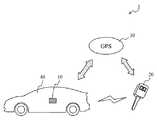
図1は、本発明の一実施形態にかかる車両盗難防止装置を用いたスマートエントリーシステム1の概略を説明する図である。図1に示す本実施形態のスマートエントリーシステム1は、車両40に搭載される車両搭載機10と、車両40の所有者などが携帯する携帯機(電子キーやスマートキーなど)20とを、構成に含む。車両搭載機10と携帯機20との間では、無線通信が行われる。また、車両搭載機10および携帯機20は、GPS人工衛星30を使用した現在位置の特定が可能である。 FIG. 1 is a diagram illustrating an outline of a smart entry system 1 using a vehicle antitheft device according to an embodiment of the present invention. A smart entry system 1 according to this embodiment shown in FIG. 1 includes a vehicle-mounted
1.スマートエントリーシステムの概要
まず、本発明の一実施形態にかかる車両盗難防止装置を用いたスマートエントリーシステム1が実現する機能の概要を説明する。
スマートエントリーシステム1では、車両搭載機10に、自機を搭載している車両40の使用を許可するために必要な専有のIDコードが予め記憶されている。また、携帯機20に、使用を許可してもらいたい車両40が専有するIDコードが予め記憶されている。つまり、特定の車両40を使用できる正規な携帯機20には、この特定の車両40が搭載する車両搭載機10に記憶されているIDコードと同じIDコードが付与されて、メモリなどに予め記憶されている。1. Outline of Smart Entry System First, an outline of functions realized by the smart entry system 1 using the vehicle antitheft device according to an embodiment of the present invention will be described.
In the smart entry system 1, a dedicated ID code necessary for permitting the use of the
携帯機20を所持する所有者などが車両搭載機10を搭載した車両40に接近すると、携帯機20と車両搭載機10との間で電波を介した無線通信が行われ、携帯機20が記憶するIDコードが車両搭載機10へ送信される(図4(a)を参照)。車両搭載機10は、携帯機20から受信したIDコードと、自機に記憶されているIDコードとの照合を行い、携帯機20から受信したIDコードが車両40が専有するIDコードであるか否かの判断を行う。ここまでが「IDコード照合フェーズ」である。 When the owner or the like who owns the
上記照合を行った結果、携帯機20から受信したIDコードと自機に記憶されているIDコードとが一致して照合が成立した場合、車両搭載機10は、自機の現在位置と、この一致したIDコードが正規に付与された携帯機20の現在位置とを取得する。そして、車両搭載機10は、IDコードが正規に付与された携帯機20が、自機の現在位置から所定の範囲内にあるか否かを判定する。ここまでが「携帯機判定フェーズ」である。 As a result of the above verification, when the ID code received from the
この携帯機判定フェーズを実行する理由は、次のとおりである。
車両搭載機10または正規の携帯機20に記憶されているIDコードが、悪意のある第三者によって盗取され、この盗取されたIDコードが端末機器などに書き込まれて不正利用される場面を考える。なお、正規の携帯機20には、車両40に付随した電子キーの他に、車両40が専有するIDコードを正規に格納した(例えば、車両製造メーカや車両販売ディーラなどによる正式な手続を経てメモリに記憶した)、スマートフォン、携帯電話、およびPDA(Personal Digital Assistant)などの可搬型情報通信端末も含まれる概念である。もちろん、IDコードを不正に格納した可搬型情報通信端末は、上述の端末機器に該当することになる。The reason for executing this portable device determination phase is as follows.
A scene in which the ID code stored in the vehicle-mounted
盗取されたIDコードが端末機器から車両搭載機10に送信された場合、盗取されたIDコードそのものは車両搭載機10が記憶しているIDコードと同じである。このため、車両搭載機10は、ソフトウエア面からIDコードの照合は問題なしと判断してしまう。しかし、盗取されたIDコードを送信した端末機器は、正規の携帯機20ではない。そこで、本発明では、正規の携帯機20か否かを判断できる情報を用いて、ハードウエア面から不正の有無を判定することを行う。
本発明では、「IDコード照合フェーズ」を行った後でさらに「携帯機判定フェーズ」を行い、「IDコード照合フェーズ」および「携帯機判定フェーズ」の両方を満足して初めて車両の使用が許可されるように制御する。When the stolen ID code is transmitted from the terminal device to the vehicle-mounted
In the present invention, after performing the “ID code verification phase”, the “portable device determination phase” is further performed, and the vehicle is permitted to be used only when both the “ID code verification phase” and the “portable device determination phase” are satisfied. To be controlled.
2.車両盗難防止装置の構成
次に、本発明の一実施形態にかかる車両盗難防止装置を、さらに詳細に説明する。
図2は、図1に示した車両搭載機10および携帯機20の詳細な構成を示す図である。図2において、車両40に搭載された車両搭載機10は、GPS通信部11と、許可判定部12と、送受信部13と、照合部14と、メモリ部15とを備えている。携帯機20は、GPS通信部21と、送受信部23と、メモリ部25とを備えている。2. Next, thevehicle antitheft device according to an embodiment of the present invention will be described in more detail.
FIG. 2 is a diagram showing a detailed configuration of the vehicle-mounted
車両搭載機10の構成を説明する。
送受信部13(特許請求の範囲における「第2の送受信手段」に対応)は、車両40に接近した、具体的には車両搭載機10が発する電波が届く所定の範囲内に進入した携帯機20に対して、携帯機20が記憶しているIDコードの送信を要求する。また、送受信部13は、要求に応じて携帯機20の送受信部23から送信されたIDコードを受信する。メモリ部15(特許請求の範囲における「第2のメモリ手段」に対応)は、車両搭載機10を搭載している車両40が専有するIDコードを記憶している。照合部14(特許請求の範囲における「照合手段」に対応)は、送受信部13が受信した携帯機20のIDコードと、メモリ部15に記憶されているIDコードとを照合する。そして、照合部14は、双方のIDコードを照合した結果に基づいて、GPS通信部11または車両40が搭載するECU16に指示を与える。
これら送受信部13、照合部14、およびメモリ部15は、照合ECUの一部を構成する。The configuration of the vehicle-mounted
The transmitter / receiver 13 (corresponding to the “second transmitter / receiver” in the claims) approaches the
The transmission /
GPS通信部11(特許請求の範囲における「位置取得手段」に対応)は、全地球測位システム(GPS:Global Positioning System)機能を有し、GPS人工衛星30と通信を行い車両搭載機10の現在位置を取得する。また、GPS通信部11は、送受信部13から照合が成立したIDコードを入手し、このIDコードが正規に付与された携帯機20の現在位置を、図示しない既存のネットワークを介して取得する。許可判定部12(特許請求の範囲における「許可判定手段」に対応)は、GPS通信部11が取得した車両搭載機10の現在位置と、IDコードが正規に付与された携帯機20の現在位置とに基づいて、送受信部13にIDコードを送信してきた携帯機20が、そのIDコードが正規に付与された携帯機20であるか否かを判定する。そして、許可判定部12は、携帯機20を判定した結果に応じて、携帯機20(の所持者)に対して車両40の使用の許可または不許可を決定し、この決定に応じた指示を車両40が搭載するECU16に与える。
これらGPS通信部11および許可判定部12は、判定ECUの一部を構成する。The GPS communication unit 11 (corresponding to “position acquisition means” in the claims) has a global positioning system (GPS) function, and communicates with the GPS
The GPS communication unit 11 and the
携帯機20の構成を説明する。
メモリ部25(特許請求の範囲における「第1のメモリ手段」に対応)は、携帯機20によって利用される車両40が専有するIDコードを記憶している。送受信部23(特許請求の範囲における「第1の送受信手段」に対応)は、車両搭載機10の送受信部13から送信されるIDコードの要求を受信する。また、送受信部23は、受信した要求に応じて、メモリ部25に記憶されているIDコードを車両搭載機10へ送信する。GPS通信部21(特許請求の範囲における「位置提供手段」に対応)は、全地球測位システム(GPS)機能を有し、GPS人工衛星30と通信を行って携帯機20の現在位置を取得する。この携帯機20の現在位置は、既存のネットワークを介して車両搭載機10に提供され、使用許可/不許可の判定に利用される。The configuration of the
The memory unit 25 (corresponding to “first memory means” in the claims) stores an ID code exclusively used by the
本発明の車両盗難防止装置は、車両搭載機10が備えるGPS通信部11および許可判定部12と、携帯機20が備えるGPS通信部21とを含んだ構成に該当する(図2の点線で囲まれた範囲)。 The vehicle antitheft device of the present invention corresponds to a configuration including the GPS communication unit 11 and
なお、各ECUは、中央演算処理装置(CPU:Central Processing Unit)、メモリ(ROM:Read Only Memory、RAM:Random Access Memory)、および入出力インタフェースなどから構成された電子制御ユニット(ECU:Electronic Control Unit)である。メモリに格納されているプログラムをCPUが解釈実行することで、GPS通信部11、許可判定部12、送受信部13、および照合部14などの機能部を実現する。
また、本発明の一実施形態にかかる車両盗難防止装置によって制御される車両40が搭載するECU16としては、例えば、車両ドアの施錠/解錠を制御するボディECUや、エンジン動作を制御するEFI−ECUなどが該当する。Each ECU is an electronic control unit (ECU: Electronic Control Unit) composed of a central processing unit (CPU), a memory (ROM: Read Only Memory, RAM: Random Access Memory), and an input / output interface. Unit). The CPU stores and executes the program stored in the memory, thereby realizing functional units such as the GPS communication unit 11, the
Moreover, as ECU16 mounted in the
3.車両盗難防止方法
次に、本発明の一実施形態にかかる車両盗難防止装置を用いたスマートエントリーシステム1で行われる車両盗難防止方法を説明する。
図3は、スマートエントリーシステム1の車両搭載機10が実行する車両盗難防止方法の処理手順を示すフローチャートである。図4は、車両盗難防止方法で行われる不正利用判定の概念を説明した図であり、(a)は正規の携帯機20が車両40にアクセスしている場面を、(b)は不正な端末機器50が車両40にアクセスしている場面を例示している。3. Vehicle Theft Prevention Method Next, a vehicle theft prevention method performed in the smart entry system 1 using the vehicle theft prevention device according to one embodiment of the present invention will be described.
FIG. 3 is a flowchart showing a processing procedure of a vehicle theft prevention method executed by the vehicle-mounted
図3に示す車両盗難防止方法は、IDコードを内部に記憶した携帯機20や端末機器50を所持する人物などが、車両40に搭載される車両搭載機10が規定する所定の範囲内に進入することで開始される。例えば、図4の例では、車両40の運転席側フロントドアに設置された車両搭載機10が規定する所定の範囲A(例えば、車両搭載機10を中心に車外側に設定された半径70cmの半球状範囲)の内側に、携帯機20や端末機器50が進入した場面を示している。
この車両搭載機10は、車両40の形状や仕様に応じて、運転席側フロントドアの他にも、運転席側リアドア、助手席側フロントドア、助手席側リアドア、バックドアなどにも設置される。なお、車両搭載機10が規定する所定の範囲Aの形状は半球状以外でもよい。また、複数の車両搭載機10がそれぞれ規定する複数の所定の範囲Aは、全て同じ形状でなくてもよい。In the vehicle theft prevention method shown in FIG. 3, a person carrying a
According to the shape and specifications of the
所定の範囲A内に特定の機器(携帯機20または端末機器50)が進入すると、車両搭載機10は、この進入した特定の機器に対して、内部に記憶しているIDコードを送信するように要求する(ステップS301)。特定の機器は、車両搭載機10からの要求に応答して、内部に記憶しているIDコードを車両搭載機10へ送信する。
この要求および応答は、典型的なスマートエントリーシステム1では、IDコードの送信を要求するリクエスト信号が、車両搭載機10から所定間隔で継続的に所定の範囲Aに送信されており、所定の範囲Aにおいてリクエスト信号を受信した特定の機器が、IDコードを車両搭載機10へ送信することによって実行される。
そして、特定の機器(携帯機20または端末機器50)からIDコードを受信すると(ステップS302、Yes)、車両搭載機10は、この受信したIDコードと、自機に記憶されているIDコードとの照合を行う(ステップS303)。When a specific device (
In the typical smart entry system 1, the request signal and the request signal for requesting transmission of the ID code are continuously transmitted from the vehicle-mounted
Then, when the ID code is received from a specific device (the
上記ステップS303における照合の結果、特定の機器(携帯機20または端末機器50)が記憶するIDコードと車両搭載機10が記憶するIDコードとが一致して照合が成立した場合(ステップS304、Yes)、車両搭載機10は、自機の現在位置を取得すると共に、照合が成立したIDコードが正規に付与された携帯機20の現在位置を取得する(ステップS305)。
次に、車両搭載機10は、取得した自機の現在位置と、照合が成立したIDコードが正規に付与された携帯機20の現在位置とに基づいて、照合が成立したIDコードが正規に付与された携帯機20が所定の範囲Aの内側に存在するか否かを判定する(ステップS306)。If the ID code stored in the specific device (the
Next, based on the acquired current position of the own machine and the current position of the
上記ステップS306において、照合が成立したIDコードが正規に付与された携帯機20が、車両搭載機10が規定する所定の範囲Aの内側に存在すると判定された場合(図4(a))、車両搭載機10は、IDコードを車両搭載機10へ送信してきた特定の機器が、IDコードが正規に付与された携帯機20であると判断する(ステップS307、Yes)。そして、車両搭載機10は、この判断に基づいて、特定の機器に対して車両40の使用を許可する、すなわち車両が搭載するECU16に対して、車両ドアのロック解除やエンジンの始動を指示する(ステップS308)。 When it is determined in step S306 that the
一方、ステップS306において、照合が成立したIDコードが正規に付与された携帯機20が、車両搭載機10が規定する所定の範囲Aの内側に存在しないと判定された場合(図4(b))、車両搭載機10は、IDコードを車両搭載機10へ送信してきた特定の機器が、IDコードが正規に付与された携帯機20ではなく、不正利用を試みている端末機器50であると判断する(ステップS307、No)。そして、車両搭載機10は、この判断に基づいて、特定の機器に対して車両40の使用を不許可とする、すなわち車両が搭載するECU16に対して、車両ドアのロック解除やエンジンの始動を指示しない(ステップS309)。 On the other hand, when it is determined in step S306 that the
同様に、上記ステップS304における照合の結果、特定の機器(携帯機20または端末機器50)が記憶するIDコードと車両搭載機10が記憶するIDコードとが一致しない場合も(ステップS305、No)、車両搭載機10は、IDコードを車両搭載機10へ送信してきた特定の機器が、この車両40ではなく別の車両に対してIDコードが正規に付与された別の携帯機20であるか、不正利用を試みている端末機器50である、と判断する。そして、車両搭載機10は、この判断に基づいて、特定の機器に対して車両40の使用を不許可とする(ステップS309)。 Similarly, when the ID code stored in the specific device (the
以上のように、本発明の一実施形態にかかる車両盗難防止装置および車両盗難防止方法によれば、IDコードを送信して車両の利用を求めてきた特定の機器に対して、IDコードの照合だけでなく、この特定の機器がIDコードが正規に付与された携帯機か否かを判定する。
これにより、車両の所有者などによって利用される正規の携帯機と、悪意のある第三者によって利用される不正な端末機器とを、判別することが可能となる。従って、車両搭載機または正規の携帯機に記憶されているIDコードが、悪意のある第三者によって盗取され、この盗取されたIDコードが端末機器などに書き込まれて不正利用される状況であっても、車両の盗難や車内の備品の盗難を防ぐことができる。As described above, according to the vehicle antitheft device and the vehicle antitheft method according to an embodiment of the present invention, the ID code is verified against a specific device that has transmitted the ID code and requested use of the vehicle. In addition, it is determined whether or not this specific device is a portable device to which an ID code is properly assigned.
As a result, it is possible to discriminate between a legitimate portable device used by the vehicle owner and the like and an unauthorized terminal device used by a malicious third party. Accordingly, an ID code stored in a vehicle-mounted device or a legitimate portable device is stolen by a malicious third party, and this stolen ID code is written on a terminal device or the like and illegally used. Even so, it is possible to prevent theft of vehicles and equipment in the vehicle.
なお、上述した本発明の車両盗難防止装置の各構成が行うそれぞれの処理は、一連の処理手順を与える車両盗難防止方法として捉えることができる。この車両盗難防止方法は、一連の処理手順をコンピュータに実行させるためのプログラムの形式で提供される。このプログラムは、コンピュータ読み取り可能な記録媒体を介してコンピュータの記憶装置に導入されてもよいし、記録媒体上から直接実行されてもよい。この記録媒体は、ROMやRAMやフラッシュメモリなどの半導体メモリ、フレキシブルディスクやハードディスクなどの磁気ディスクメモリ、CD−ROMやDVDやBDなどの光ディスクメモリ、およびメモリカードなどをいい、電話回線や搬送路などの通信媒体も含まれる。 In addition, each process which each structure of the vehicle antitheft device of this invention mentioned above can be regarded as a vehicle antitheft method which gives a series of processing procedures. This vehicle theft prevention method is provided in the form of a program for causing a computer to execute a series of processing procedures. This program may be introduced into a computer storage device via a computer-readable recording medium, or may be directly executed from the recording medium. This recording medium is a semiconductor memory such as ROM, RAM, or flash memory, a magnetic disk memory such as a flexible disk or a hard disk, an optical disk memory such as a CD-ROM, DVD, or BD, and a memory card. Communication media such as are also included.
また、本発明が提供する技術の一実施例として図面を用いた詳細な説明を行ったが、この図面および詳細な説明に記載された構成要素の中には、課題解決のために必須な構成要素だけでなく、本技術を例示するために課題解決のためには必須でない構成要素も含まれ得る。よって、図面や詳細な説明に記載されているからといって、全ての構成要素が発明に必須の構成要素であるわけではない。
さらに、上述した実施形態は、本発明における技術を例示するためのものであるから、特許請求の範囲またはその均等の範囲において、種々の変更、置き換え、付加、省略などを行うことができる。In addition, the detailed description using the drawings has been given as an embodiment of the technology provided by the present invention, but some of the components described in the drawings and the detailed description are indispensable for solving the problems. Not only elements but also components that are not essential for solving the problem in order to illustrate the present technology may be included. Therefore, just because they are described in the drawings and detailed description, not all the constituent elements are essential elements for the invention.
Furthermore, since the above-described embodiment is for exemplifying the technique in the present invention, various modifications, replacements, additions, omissions, and the like can be made within the scope of the claims or an equivalent scope thereof.
本発明は、車両に搭載されるワイヤレスキーシステムやキーレスエントリーシステムなどに利用可能であり、特に第三者の不正使用を正確に排除して盗難を防ぎたい場合に有用である。 INDUSTRIAL APPLICABILITY The present invention can be used for a wireless key system or a keyless entry system mounted on a vehicle, and is particularly useful when it is desired to prevent illegal use by a third party accurately and prevent theft.
1 スマートエントリーシステム
10 車両搭載機
11、21 GPS通信部
12 許可判定部
13、23 送受信部
14 照合部
15、25 メモリ部
16 ECU
20 携帯機
30 GPS人工衛星
40 車両
50 端末機器DESCRIPTION OF SYMBOLS 1
20
Claims (7)
Translated fromJapanese前記携帯機に備えられ、当該携帯機の現在位置を提供する位置提供手段と、
前記車両搭載機に備えられ、当該車両搭載機によって受信されかつ照合が成立したIDコードについて当該IDコードが正規に付与された携帯機の現在位置および当該車両搭載機の現在位置を、それぞれ取得する位置取得手段と、
前記車両搭載機に備えられ、前記照合が成立したIDコードが正規に付与された携帯機の現在位置が前記車両搭載機の現在位置から所定の範囲内にある場合に、前記照合が成立したIDコードに基づく車両の使用を許可する許可判定手段とを備える、車両盗難防止装置。A vehicle antitheft device used in a system that determines use of a vehicle based on a collation result of an ID code wirelessly communicated between a portable device and a vehicle-mounted device,
A position providing means provided in the portable device for providing a current position of the portable device;
The present position of the portable device and the current position of the vehicle-mounted device, which are provided in the vehicle-mounted device and received by the vehicle-mounted device and for which the ID code has been properly verified, are respectively acquired. Position acquisition means;
The ID for which the collation is established when the current position of the portable device that is provided in the vehicle-mounted machine and the ID code for which the collation is established is properly given is within a predetermined range from the current position of the vehicle-equipped machine. A vehicle antitheft device comprising: permission determination means for permitting use of the vehicle based on the code.
前記携帯機は、
IDコードを記憶する第1のメモリ手段と、
前記車両搭載機から受信する要求に応じて、前記第1のメモリ手段に記憶するIDコードを前記車両搭載機へ送信する第1の送受信手段と、
GPS機能を用いて携帯機の現在位置を提供する位置提供手段とを備え、
前記車両搭載機は、
搭載される車両が専有するIDコードを記憶する第2のメモリ手段と、
前記携帯機からIDコードを受信する第2の送受信手段と、
前記第2の送受信手段が受信したIDコードと、前記第2のメモリ手段が記憶するIDコードとの、照合を行う照合手段と、
前記照合手段において双方のIDコードの照合が成立した場合、当該照合が成立したIDコードが正規に付与された携帯機の現在位置および当該車両搭載機の現在位置を、GPS機能を用いて取得する位置取得手段と、
前記照合が成立したIDコードが正規に付与された携帯機の現在位置が前記車両搭載機の現在位置から所定の範囲内にある場合に、前記照合が成立したIDコードに基づく車両の使用を許可する許可判定手段とを備える、スマートエントリーシステム。A smart entry system that determines use of a vehicle based on a collation result of an ID code wirelessly communicated between a portable device and a vehicle-mounted device,
The portable device is
First memory means for storing an ID code;
First transmission / reception means for transmitting an ID code stored in the first memory means to the vehicle-mounted machine in response to a request received from the vehicle-mounted machine;
A position providing means for providing the current position of the portable device using the GPS function,
The vehicle-mounted machine is
Second memory means for storing an ID code exclusively used by the mounted vehicle;
Second transmitting / receiving means for receiving an ID code from the portable device;
Collation means for collating the ID code received by the second transmission / reception means and the ID code stored in the second memory means;
When collation of both ID codes is established in the collation means, the current position of the portable device to which the ID code for which the collation is established is properly assigned and the current position of the vehicle-mounted device are acquired using the GPS function. Position acquisition means;
Permits the use of a vehicle based on the ID code for which the verification is established when the current position of the portable device to which the ID code for which the verification has been established is properly provided is within a predetermined range from the current position of the vehicle-mounted device. A smart entry system comprising permission determination means.
前記携帯機が、前記車両搭載機から受信する要求に応じて、内部に記憶するIDコードを前記車両搭載機へ送信するステップと、
前記車両搭載機が、
前記携帯機からIDコードを受信するステップと、
前記携帯機から受信したIDコードと自機内部に記憶するIDコードとの照合を行うステップと、
前記IDコードの照合が成立した場合、当該照合が成立したIDコードが正規に付与された携帯機の現在位置および当該車両搭載機の現在位置を、GPS機能を用いて取得するステップと、
前記照合が成立したIDコードが正規に付与された携帯機の現在位置が前記車両搭載機の現在位置から所定の範囲内にある場合に、前記照合が成立したIDコードに基づく車両の使用を許可するステップとを含む、車両盗難防止方法。A vehicle theft prevention method executed in a system for determining use of a vehicle based on a collation result of an ID code wirelessly communicated between a portable device and a vehicle-mounted device,
In response to a request received from the vehicle-mounted device, the portable device transmits an ID code stored therein to the vehicle-mounted device;
The vehicle-mounted machine is
Receiving an ID code from the portable device;
Collating the ID code received from the portable device with the ID code stored in the device itself;
If the ID code verification is established, a step of acquiring the current position of the portable device and the current position of the vehicle-mounted device to which the ID code for which the verification has been established is properly assigned using a GPS function;
Permits the use of a vehicle based on the ID code for which the verification is established when the current position of the portable device to which the ID code for which the verification has been established is properly provided is within a predetermined range from the current position of the vehicle-mounted device. And a vehicle theft prevention method.
Priority Applications (1)
| Application Number | Priority Date | Filing Date | Title |
|---|---|---|---|
| JP2012247561AJP2014094680A (en) | 2012-11-09 | 2012-11-09 | Vehicular anti-theft device and method, and smart entry system |
Applications Claiming Priority (1)
| Application Number | Priority Date | Filing Date | Title |
|---|---|---|---|
| JP2012247561AJP2014094680A (en) | 2012-11-09 | 2012-11-09 | Vehicular anti-theft device and method, and smart entry system |
Publications (1)
| Publication Number | Publication Date |
|---|---|
| JP2014094680Atrue JP2014094680A (en) | 2014-05-22 |
Family
ID=50938139
Family Applications (1)
| Application Number | Title | Priority Date | Filing Date |
|---|---|---|---|
| JP2012247561APendingJP2014094680A (en) | 2012-11-09 | 2012-11-09 | Vehicular anti-theft device and method, and smart entry system |
Country Status (1)
| Country | Link |
|---|---|
| JP (1) | JP2014094680A (en) |
Cited By (8)
| Publication number | Priority date | Publication date | Assignee | Title |
|---|---|---|---|---|
| JP2016068939A (en)* | 2014-10-01 | 2016-05-09 | 株式会社マール・コミュニケーションズ | Antitheft system |
| JP2016155526A (en)* | 2015-02-26 | 2016-09-01 | 株式会社日本自動車部品総合研究所 | Vehicle anti-theft device |
| WO2019059138A1 (en)* | 2017-09-22 | 2019-03-28 | 株式会社オートネットワーク技術研究所 | Reception device, communication system, distance determination method, and computer program |
| US10358115B2 (en) | 2017-10-23 | 2019-07-23 | Hyundai Motor Company | Vehicle, vehicle security system and vehicle security method |
| CN112238838A (en)* | 2020-10-14 | 2021-01-19 | 江苏广宇协同科技发展研究院有限公司 | Internet of things driving safety management system |
| KR20210039575A (en) | 2019-10-02 | 2021-04-12 | 콘티넨탈 오토모티브 게엠베하 | Smart key unit and operating method of smart key system |
| CN113715774A (en)* | 2020-05-26 | 2021-11-30 | 丰田自动车株式会社 | Vehicle control device, vehicle control system, and recording medium |
| CN113928265A (en)* | 2021-10-20 | 2022-01-14 | 车主邦(北京)科技有限公司 | Vehicle anti-theft method and device based on charging pile |
- 2012
- 2012-11-09JPJP2012247561Apatent/JP2014094680A/enactivePending
Cited By (10)
| Publication number | Priority date | Publication date | Assignee | Title |
|---|---|---|---|---|
| JP2016068939A (en)* | 2014-10-01 | 2016-05-09 | 株式会社マール・コミュニケーションズ | Antitheft system |
| JP2016155526A (en)* | 2015-02-26 | 2016-09-01 | 株式会社日本自動車部品総合研究所 | Vehicle anti-theft device |
| WO2019059138A1 (en)* | 2017-09-22 | 2019-03-28 | 株式会社オートネットワーク技術研究所 | Reception device, communication system, distance determination method, and computer program |
| US10358115B2 (en) | 2017-10-23 | 2019-07-23 | Hyundai Motor Company | Vehicle, vehicle security system and vehicle security method |
| KR20210039575A (en) | 2019-10-02 | 2021-04-12 | 콘티넨탈 오토모티브 게엠베하 | Smart key unit and operating method of smart key system |
| CN113715774A (en)* | 2020-05-26 | 2021-11-30 | 丰田自动车株式会社 | Vehicle control device, vehicle control system, and recording medium |
| JP2021188279A (en)* | 2020-05-26 | 2021-12-13 | トヨタ自動車株式会社 | Vehicle control apparatus, vehicle control system, and vehicle control program |
| CN113715774B (en)* | 2020-05-26 | 2024-02-13 | 丰田自动车株式会社 | Vehicle control devices, vehicle control systems and recording media |
| CN112238838A (en)* | 2020-10-14 | 2021-01-19 | 江苏广宇协同科技发展研究院有限公司 | Internet of things driving safety management system |
| CN113928265A (en)* | 2021-10-20 | 2022-01-14 | 车主邦(北京)科技有限公司 | Vehicle anti-theft method and device based on charging pile |
Similar Documents
| Publication | Publication Date | Title |
|---|---|---|
| JP2014094680A (en) | Vehicular anti-theft device and method, and smart entry system | |
| EP1757499B1 (en) | In-vehicle antitheft device and central authentication device | |
| US7432796B2 (en) | Security control system for managing registration of ID codes for portable devices | |
| US10147257B2 (en) | Systems and methods for user based vehicle access control | |
| EP1564691B1 (en) | Security controller for use with a portable device and a management apparatus, and corresponding security control method | |
| CN112644423B (en) | System and method for starting a vehicle using a secure password entry system | |
| KR102071406B1 (en) | In-vehicle Devices and Authentication Systems | |
| JP5170177B2 (en) | Vehicle anti-theft device | |
| EP2866207A1 (en) | System and method for authenticating components of a vehicle | |
| US20060143463A1 (en) | Keyless entry system and keyless entry method | |
| US9079554B2 (en) | Method and apparatus for vehicle hardware theft prevention | |
| WO2015033527A1 (en) | Control device and electronic key system | |
| KR101745443B1 (en) | Authentication system for driver of vehicle | |
| WO2014119225A1 (en) | Control system | |
| KR20080106954A (en) | How to protect your garden, especially your vehicle, from unauthorized use | |
| JP2005178666A (en) | Anti-theft system | |
| US9352723B2 (en) | Theft prevention device and theft prevention method | |
| CN112837445A (en) | Reducing latency in a vehicle passive entry system | |
| JP2017160703A (en) | Electronic key system | |
| CN112652094A (en) | System and method for creating vehicle keyless entry password and/or keypad code | |
| JP2013126197A (en) | Antitheft system | |
| JP2020113065A (en) | Information management system | |
| JP3649164B2 (en) | Car security system and car security program | |
| JP2008132914A (en) | Vehicular anti-theft device | |
| JP2006021598A (en) | Vehicle anti-theft system |