JP2014093770A - Protection cover for mobile device - Google Patents
Protection cover for mobile deviceDownload PDFInfo
- Publication number
- JP2014093770A JP2014093770AJP2013133453AJP2013133453AJP2014093770AJP 2014093770 AJP2014093770 AJP 2014093770AJP 2013133453 AJP2013133453 AJP 2013133453AJP 2013133453 AJP2013133453 AJP 2013133453AJP 2014093770 AJP2014093770 AJP 2014093770A
- Authority
- JP
- Japan
- Prior art keywords
- protective cover
- mobile device
- display screen
- cover
- see
- Prior art date
- Legal status (The legal status is an assumption and is not a legal conclusion. Google has not performed a legal analysis and makes no representation as to the accuracy of the status listed.)
- Pending
Links
- 230000001681protective effectEffects0.000claimsdescription265
- 230000003014reinforcing effectEffects0.000claimsdescription58
- 230000002093peripheral effectEffects0.000claimsdescription20
- 229920003002synthetic resinPolymers0.000claimsdescription10
- 239000000057synthetic resinSubstances0.000claimsdescription10
- 239000005341toughened glassSubstances0.000claimsdescription6
- 230000004308accommodationEffects0.000claimsdescription5
- 239000000696magnetic materialSubstances0.000claimsdescription4
- 239000004020conductorSubstances0.000claimsdescription3
- 230000035939shockEffects0.000abstract1
- 239000004744fabricSubstances0.000description13
- 239000000463materialSubstances0.000description9
- 230000004927fusionEffects0.000description6
- 238000013461designMethods0.000description4
- 238000003825pressingMethods0.000description4
- 230000000694effectsEffects0.000description3
- 238000000034methodMethods0.000description3
- 230000002787reinforcementEffects0.000description3
- 238000001514detection methodMethods0.000description2
- 239000012790adhesive layerSubstances0.000description1
- 239000002390adhesive tapeSubstances0.000description1
- 230000000903blocking effectEffects0.000description1
- 239000003086colorantSubstances0.000description1
- 238000004891communicationMethods0.000description1
- 238000011161developmentMethods0.000description1
- 230000018109developmental processEffects0.000description1
- 238000005516engineering processMethods0.000description1
- 238000001746injection mouldingMethods0.000description1
- 239000004973liquid crystal related substanceSubstances0.000description1
- 238000003754machiningMethods0.000description1
- 238000004519manufacturing processMethods0.000description1
- 239000002184metalSubstances0.000description1
- 239000007769metal materialSubstances0.000description1
- 238000012986modificationMethods0.000description1
- 230000004048modificationEffects0.000description1
- 230000000149penetrating effectEffects0.000description1
- 238000003860storageMethods0.000description1
- 229920001169thermoplasticPolymers0.000description1
- 239000004416thermosoftening plasticSubstances0.000description1
Images


Classifications
- A—HUMAN NECESSITIES
- A45—HAND OR TRAVELLING ARTICLES
- A45C—PURSES; LUGGAGE; HAND CARRIED BAGS
- A45C11/00—Receptacles for purposes not provided for in groups A45C1/00-A45C9/00
Landscapes
- Casings For Electric Apparatus (AREA)
- Telephone Set Structure (AREA)
Abstract
Description
Translated fromJapanese本発明は、スマートフォンやタブレットPCなどの携帯用のモバイル機器の前面部を保護する機能を行いながら、表示画面に表示される主な情報と機能を保護カバーを開かなくても確認したり外部からタッチ操作したりできるモバイル機器用の保護カバーに関する。 The present invention can confirm the main information and functions displayed on the display screen without opening the protective cover while performing the function of protecting the front part of a portable mobile device such as a smartphone or tablet PC, or from the outside. The present invention relates to a protective cover for mobile devices that can be touch-operated.
最近の携帯電話の技術の発展には目を見張るものがあり、これに伴い、スマートフォンやタブレットPCなどのモバイル機器が上市されつつあり、携帯用の通信機器の大変革が起きている。 Recent developments in mobile phone technology are striking. Along with this, mobile devices such as smartphones and tablet PCs are on the market, and major changes in portable communication devices are taking place.
とりわけ、スマートフォンやタブレットPCなどのモバイル機器は、電話機能とインターネット機能はもとより、ノート型パソコン、個人用の携帯情報端末(PDA)、パーソナル・メディア・プレーヤー(PMP)などの高価な携帯機器を統合した様々な性能を有しており、特に、前面部はフルタッチ表示画面となっているため非常に高価な製品であるといえ、使用中に表示画面を保護しながら使用する必要がある。 In particular, mobile devices such as smartphones and tablet PCs integrate expensive mobile devices such as notebook computers, personal digital assistants (PDAs), and personal media players (PMP), as well as telephone and Internet functions. In particular, since the front portion is a full touch display screen, it can be said that the product is very expensive, and it is necessary to protect the display screen during use.
このため、破損を防ぎ、且つ、表示画面の表面が引っ掻かれたり汚れたりすることを防ぐために、種々の材質とデザイン及び機能性を有する保護カバーと、このような保護カバーを有する保護ケースが種々上市されており、中でも、タッチ表示画面を保護するためのいわゆる「フリップカバー」と呼ばれる製品が汎用されているのが現状である。 For this reason, in order to prevent damage and prevent the surface of the display screen from being scratched or soiled, there are protective covers having various materials, designs and functions, and protective cases having such protective covers. There are various products on the market, and in particular, a so-called “flip cover” for protecting the touch display screen is widely used.
しかしながら、この種の従来の保護カバーは、液晶画面に表示される内容を確認する度にカバーを頻繁に開閉することを余儀なくされるため、モバイル機器の使用が煩雑であるという不都合があった。 However, this type of conventional protective cover has the inconvenience that the mobile device is complicated to use because the cover must be frequently opened and closed each time the content displayed on the liquid crystal screen is confirmed.
また、モバイル機器の使用回数に比例してカバーの開閉動作が繰り返し行われるため、保護カバーと、連結部及び背面カバーなどが毀損され易くなる結果、取り替え周期が短くなり、ユーザに経済的な負担を与えてしまうという不都合があった。 In addition, the opening and closing operation of the cover is repeatedly performed in proportion to the number of times the mobile device is used, so that the protective cover, the connecting portion, the back cover, etc. are easily damaged, resulting in a short replacement cycle and an economical burden on the user. There was the inconvenience of giving.
これらの理由から、ユーザは、モバイル機器の前面部を外部の衝撃によって破損しないように保護しながらも、保護カバーを開かなくても表示画面に表示された内容を確認したりタッチ操作したりできるモバイル機器用の保護カバーを切望しているのが現状である。 For these reasons, the user can check the content displayed on the display screen and perform touch operations without opening the protective cover while protecting the front part of the mobile device from being damaged by an external impact. The current situation is the desire for a protective cover for mobile devices.
本発明の目的は、スマートフォンや小型のタブレットPCなどの携帯用のモバイル機器の前面部を保護する機能を行いながら、表示画面に表示される主な情報と機能を保護カバーを開かなくても確認したり外部からタッチ操作したりすることができるモバイル機器用の保護カバーを提供することにある。 The purpose of the present invention is to confirm the main information and functions displayed on the display screen without opening the protective cover while performing the function of protecting the front part of portable mobile devices such as smartphones and small tablet PCs. An object of the present invention is to provide a protective cover for a mobile device that can be touched or operated from the outside.
上述した目的を達成するために、本発明は、携帯用のモバイル機器の表示画面を保護するための保護カバーにおいて、前記保護カバーは、前記モバイル機器が駆動されるときに、前記表示画面に表示される主な情報を前記保護カバーが前記表示画面の上に覆われた状態で確認するための透視部を備えることを特徴とするモバイル機器用の保護カバーを提供する。 In order to achieve the above object, the present invention provides a protective cover for protecting a display screen of a portable mobile device, wherein the protective cover is displayed on the display screen when the mobile device is driven. Provided is a protective cover for a mobile device, comprising a fluoroscopic part for confirming main information to be performed in a state where the protective cover is covered on the display screen.
本発明の一実施形態によれば、前記透視部は、前記モバイル機器が駆動されるときに、前記表示画面における主な情報の表示領域に対応する位置に形成されることが好ましい。 According to an embodiment of the present invention, it is preferable that the fluoroscopic part is formed at a position corresponding to a display area of main information on the display screen when the mobile device is driven.
本発明の他の実施形態によれば、前記透視部は、表示画面と同じ大きさを有することが好ましい。 According to another embodiment of the present invention, the fluoroscopic part preferably has the same size as the display screen.
本発明のさらに他の実施形態によれば、前記保護カバーは、前記モバイル機器の背面に取り付けられている背面カバーをはずしてさらに取り付ける取付カバーを備え、前記取付カバーと連結部材によって連結されて前記表示画面を保護することが好ましい。 According to still another embodiment of the present invention, the protective cover includes a mounting cover that is further mounted by removing a back cover that is mounted on a back surface of the mobile device, and is connected to the mounting cover by a connecting member. It is preferable to protect the display screen.
本発明のさらに他の実施形態によれば、前記透視部は、保護カバーの前面部の一部に開口部が形成され、この開口部には、前記表示画面を保護するための透視部材が配設されることが好ましい。 According to still another embodiment of the present invention, the see-through portion has an opening formed in a part of the front portion of the protective cover, and a see-through member for protecting the display screen is arranged in the opening. It is preferable to be provided.
本発明のさらに他の実施形態によれば、前記透視部材は、開口部に対応するように取り付けられて外部に露出される透視画面部と、この透視画面部の外周縁に形成される固定部と、を備え、前記固定部は、前記保護カバーの内部に挿設されて一体に組み立てられることが好ましい。 According to still another embodiment of the present invention, the see-through member is attached so as to correspond to the opening portion and exposed to the outside, and a fixing portion formed on the outer peripheral edge of the see-through screen portion It is preferable that the fixing portion is inserted into the protective cover and assembled together.
本発明のさらに他の実施形態によれば、前記透視部材は、導電性機能を有する透明または半透明の合成樹脂、強化ガラスまたはハーフミラーから製作されて、外部から表示画面をタッチして操作可能であることが好ましい。 According to still another embodiment of the present invention, the see-through member is manufactured from a transparent or translucent synthetic resin having a conductive function, tempered glass, or a half mirror, and can be operated by touching a display screen from the outside. It is preferable that
本発明のさらに他の実施形態によれば、前記透視部材は、前記表示画面に表示される主な情報または表示内容の位置及び外周の大きさに対応するように形成されることが好ましい。 According to still another embodiment of the present invention, it is preferable that the fluoroscopic member is formed so as to correspond to the position of the main information or display content displayed on the display screen and the size of the outer periphery.
本発明のさらに他の実施形態によれば、前記透視部材は、前記保護カバーに横方向に形成されることが好ましい。 According to still another embodiment of the present invention, it is preferable that the see-through member is formed laterally on the protective cover.
本発明のさらに他の実施形態によれば、前記透視部材は、前記保護カバーに縦方向に長尺に形成されることが好ましい。 According to still another embodiment of the present invention, it is preferable that the see-through member is formed on the protective cover so as to be long in the vertical direction.
本発明のさらに他の実施形態によれば、前記透視部材は、前記保護カバーに横方向または縦方向に形成されるが、片側に偏って形成されることが好ましい。 According to still another embodiment of the present invention, the see-through member is formed on the protective cover in a horizontal direction or a vertical direction, but is preferably formed to be biased to one side.
本発明のさらに他の実施形態によれば、前記固定部は、前記透視部材を除く保護カバーの残りの領域に延設され、前記固定部の両側面には貼合部材が配設されて外側部材及び内側部材と貼り合わせられることが好ましい。 According to still another embodiment of the present invention, the fixing portion is extended to the remaining area of the protective cover excluding the see-through member, and a bonding member is disposed on both sides of the fixing portion. It is preferable to be bonded to the member and the inner member.
本発明のさらに他の実施形態によれば、前記固定部と、前記外側部材及び内側部材の間には、補強部材がさらに介装されることが好ましい。 According to still another embodiment of the present invention, it is preferable that a reinforcing member is further interposed between the fixed portion, the outer member, and the inner member.
本発明のさらに他の実施形態によれば、前記保護カバーは、前記表示画面の外周に沿って周縁部が形成され、前記透視部材は、前記表示画面と対応する大きさに前記周縁部の領域内に形成されて外部に露出されることが好ましい。 According to still another embodiment of the present invention, the protective cover has a peripheral portion formed along an outer periphery of the display screen, and the fluoroscopic member has a size corresponding to the display screen. It is preferably formed inside and exposed to the outside.
本発明のさらに他の実施形態によれば、前記保護カバーには、前記携帯用のモバイル機器の前面部に配設された機能部品に対応する位置に機能孔が穿設されることが好ましい。 According to still another embodiment of the present invention, it is preferable that a functional hole is formed in the protective cover at a position corresponding to a functional component disposed on a front portion of the portable mobile device.
前記機能孔は、通話スピーカー孔、正面カメラ孔、ユーザ認識孔及び調光センサ孔の選択的な組み合わせからなることが好ましい。なお、前記保護カバーの一方の側における前記携帯用のモバイル機器の機能ボタン部またはタッチボタン部に対応する位置に押下ボタン表示部がさらに形成されることが好ましい。 Preferably, the functional hole is a selective combination of a call speaker hole, a front camera hole, a user recognition hole, and a light control sensor hole. It is preferable that a push button display unit is further formed at a position corresponding to the function button unit or the touch button unit of the portable mobile device on one side of the protective cover.
本発明のさらに他の実施形態によれば、前記透視部材は、前記保護カバーに埋設されるが、その底面部が前記表示画面に接触しないように微隙間をあけて埋設されることが好ましい。 According to still another embodiment of the present invention, the see-through member is embedded in the protective cover, but is preferably embedded with a small gap so that the bottom surface portion does not contact the display screen.
本発明のさらに他の実施形態によれば、前記携帯用のモバイル機器の背面の一方の側には取付感知部が配設されて、この取付感知部が前記取付カバーに配設される取付認識部と接触式または非接触式で接続されることによって前記保護カバーの取付有無が認識され、前記取付カバーが取り付けられるときには、携帯用のモバイル機器の表示画面に表示される主な情報が前記保護カバーの透視部材の領域にしか表示されないことが好ましい。 According to still another embodiment of the present invention, an attachment sensing unit is disposed on one side of the back surface of the portable mobile device, and the attachment sensing unit is disposed on the attachment cover. When the mounting cover is attached, the main information displayed on the display screen of a portable mobile device is the protection. It is preferable that it is displayed only in the region of the transparent member of the cover.
本発明のさらに他の実施形態によれば、前記保護カバーには、前記表示画面に前記保護カバーが覆われている状態であるか否かを判別する感知手段が内蔵され、前記感知手段は、前記モバイル機器の背面に設けられる回路接続部と連結される前記取付カバーの接続端子部と有線または無線で開閉状態を送受信しながら前記モバイル機器の内部の制御回路部と相互連動して保護カバーの開閉状態に応じて前記表示画面をオンまたはオフにすることが好ましい。 According to still another embodiment of the present invention, the protective cover includes a sensing unit for determining whether or not the display screen is covered with the protective cover, and the sensing unit includes: The connection terminal portion of the mounting cover connected to the circuit connection portion provided on the back surface of the mobile device is connected to the control circuit portion inside the mobile device while transmitting / receiving the open / closed state by wire or wirelessly. It is preferable to turn the display screen on or off according to the open / close state.
本発明のさらに他の実施形態によれば、前記保護カバーは、外側部材と内側部材を備え、前記透視部材は、透視画面部と、この透視画面部の周縁部に形成される固定部と、を備えて、前記固定部が前記外側部材と内側部材との間に挟持されて一体に組み立てられることが好ましい。 According to still another embodiment of the present invention, the protective cover includes an outer member and an inner member, the see-through member includes a see-through screen portion, and a fixing portion formed on a peripheral portion of the see-through screen portion, It is preferable that the fixing portion is sandwiched between the outer member and the inner member and assembled together.
前記外側部材と内側部材との間には補強部材がさらに介装され、前記固定部は、前記補強部材の内部に嵌着されることが好ましい。 It is preferable that a reinforcing member is further interposed between the outer member and the inner member, and the fixing portion is fitted inside the reinforcing member.
さらに、前記補強部材は、合成樹脂製の第1の補強板及び第2の補強板を備え、前記第1の補強板と第2の補強板との間に形成された載置部に前記固定部が収容され、前記載置部の内側に前記開口部と連通するように形成された透視ウィンドウを介して前記透視画面部が外部に露出されることが好ましい。 Further, the reinforcing member includes a first reinforcing plate and a second reinforcing plate made of synthetic resin, and the fixing member is fixed to a mounting portion formed between the first reinforcing plate and the second reinforcing plate. It is preferable that the fluoroscopic screen portion is exposed to the outside through a fluoroscopic window that is formed so as to communicate with the opening inside the placement portion.
前記第1の補強板と第2の補強板、及び前記載置部と固定部は貼合部材によって一体に貼り合わせられ、前記外側部材と内側部材は、前記第1の補強板と第2の補強板の各外側面に前記貼合部材によって一体に貼り合わせられることが好ましい。 The first reinforcing plate and the second reinforcing plate, and the mounting portion and the fixing portion are bonded together by a bonding member, and the outer member and the inner member are bonded to the first reinforcing plate and the second reinforcing plate. It is preferable that the outer side surfaces of the reinforcing plate are integrally bonded by the bonding member.
前記載置部の一方の側には、フレキシブルプリント基板(FPCB)が収容される収容溝がさらに凹設されることが好ましい。 It is preferable that an accommodation groove for accommodating a flexible printed circuit board (FPCB) is further recessed on one side of the placement portion.
前記フレキシブルプリント基板(FPCB)の一方の端には、前記補強部材の内部に収容されて保護カバーの開閉有無を感知する感知手段が配設され、フレキシブルプリント基板(FPCB)の途中部は、保護カバーの一方の端部と連結される連結部材の内部に引き込まれ、前記フレキシブルプリント基板(FPCB)の他方の端は、前記連結部材と連結されてモバイル機器の背面に取り付けられる取付カバーの内側に配設される接続端子部と連結されて、この接続端子部が前記携帯用のモバイル機器の背面に設けられた回路接続部と接続されて保護カバーの開閉有無に応じて前記表示画面をオン/オフにすることが好ましい。 One end of the flexible printed circuit board (FPCB) is provided with a sensing means that is accommodated in the reinforcing member and senses whether the protective cover is opened or closed. The middle part of the flexible printed circuit board (FPCB) is protected. The flexible printed circuit board (FPCB) is pulled into the inside of a connecting member connected to one end of the cover, and the other end of the flexible printed circuit board (FPCB) is connected to the inner side of the mounting cover attached to the back of the mobile device. The connection terminal is connected to the disposed connection terminal, and the connection terminal is connected to a circuit connection provided on the back of the portable mobile device to turn on / off the display screen according to whether the protective cover is opened or closed. It is preferable to turn it off.
さらに、前記感知手段は、磁気センサ、照度センサ、フォトセンサまたは近接センサであることが好ましい。 Furthermore, the sensing means is preferably a magnetic sensor, an illuminance sensor, a photo sensor, or a proximity sensor.
本発明によれば、たとえスマートフォンなどの携帯用のモバイル機器の前面部に外部から衝撃が加えられても安全に保護することができ、しかも、保護カバーを開かなくても表示画面の内容を確認したりタッチ操作したりできるので、保護カバーを取り付けてモバイル機器を安全に保護しながらも、モバイル機器の機能を十分に使いこなすことが可能になる。 According to the present invention, even if an external impact is applied to the front part of a portable mobile device such as a smartphone, it can be safely protected, and the contents of the display screen can be confirmed without opening the protective cover. Since it can be operated and touch-operated, it is possible to fully use the functions of the mobile device while attaching the protective cover to protect the mobile device safely.
また、保護カバーに内蔵される感知手段と、取付カバーに配設される取付感知部によって保護カバーの取付有無をモバイル機器に認識させ、また、保護カバーの開閉有無をも認識する保護カバーを提供することにより、ユーザは、保護カバーを頻繁に開かなくても、外部から透視部材を介してモバイル機器を操作することが可能になる。 Also provided is a protective cover that allows the mobile device to recognize whether the protective cover is attached or not, and whether the protective cover is opened or closed, by means of a sensing means built into the protective cover and an attachment sensing portion provided on the attachment cover. By doing so, the user can operate the mobile device from the outside via the fluoroscopic member without frequently opening the protective cover.
以下の図面は単に例示のために提供されるものであり、本発明の範囲を制限するためのものではない。 The following drawings are provided for purposes of illustration only and are not intended to limit the scope of the invention.
以下、添付図面に基づき、本発明の好適な実施形態に係るモバイル機器保護カバーについて詳述する。この実施形態においては、モバイル機器に配設された背面カバーをはずした後、保護カバーと、連結部及び背面カバーからなるいわゆる「フリップカバー」と呼ばれる保護ケースに適用したものを例にとって説明するが、本発明は、これに何ら限定されるものではなく、モバイル機器の種類による種々の保護ケースに適用された保護カバーにいずれも適用可能であるということはいうまでもない。 Hereinafter, a mobile device protective cover according to a preferred embodiment of the present invention will be described in detail with reference to the accompanying drawings. In this embodiment, an example will be described in which a rear cover disposed on a mobile device is removed and then applied to a protective case called a “flip cover” including a protective cover, a connecting portion, and a rear cover. The present invention is not limited to this, and it goes without saying that any of the protective covers applied to various protective cases depending on the type of mobile device can be applied.
なお、以下の種々の実施形態の説明に際して用いられる同じ符号及び名称は、重複してそのまま用いる。 In addition, the same code | symbol and name used in the description of the following various embodiments overlap and are used as it is.
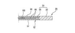
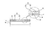
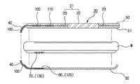
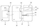
図1A及び図1Bは、本発明の一実施形態に係るモバイル機器用の保護カバーの構成を示す正面図とa−a線の拡大断面図であり、図2Aから図2Cは、本発明の他の実施形態に係るモバイル機器用の保護カバーを示す正面図と、要部断面図及びb−b線拡大断面図であり、図3A及び図3Bは、本発明のさらに他の実施形態に係るモバイル機器用の保護カバーを示す正面図と平断面図であり、図4A及び図4Bは、本発明のさらに他の実施形態に係るモバイル機器用の保護カバーの組立構造を示す組立断面図と分解断面図であり、図5から図7は、本発明のさらに他の実施形態に係る補強部材を有するモバイル機器用の保護カバーを示す組立断面図である。 1A and 1B are a front view and an enlarged sectional view taken along line aa showing the configuration of a protective cover for a mobile device according to an embodiment of the present invention. FIGS. 2A to 2C are other views of the present invention. FIG. 3A is a front view showing a protective cover for a mobile device according to an embodiment of the present invention, and FIG. 3A and FIG. FIG. 4A and FIG. 4B are an assembled sectional view and an exploded sectional view showing an assembly structure of a protective cover for a mobile device according to still another embodiment of the present invention. FIGS. 5 to 7 are assembled cross-sectional views illustrating a protective cover for a mobile device having a reinforcing member according to still another embodiment of the present invention.
図8は、本発明のさらに他の実施形態に係る保護カバー取付有無感知手段の構成を示す分解正面図と平断面図であり、図9及び図10は、本発明のさらに他の実施形態に係る保護カバー開閉有無感知手段の構成を示す分解正面図である。 FIG. 8 is an exploded front view and a plan sectional view showing a configuration of a protective cover attachment presence / absence sensing means according to still another embodiment of the present invention, and FIGS. 9 and 10 show still another embodiment of the present invention. It is a disassembled front view which shows the structure of the protection cover opening / closing detection means which concerns.
先ず、本発明の一実施形態に係るモバイル機器用の保護カバーの基本構成について詳細に説明する。 First, a basic configuration of a protective cover for a mobile device according to an embodiment of the present invention will be described in detail.
本発明に係るモバイル機器用の保護カバー10の最大の特徴は、図1Aから図3Bに示すように、前記モバイル機器Mが駆動されるときに、前記表示画面Pに表示される主な情報Fを前記保護カバー10が前記表示画面Pの上に覆われた状態で確認するための透視部20が配設されているというところにある。 The greatest feature of the
この実施形態における保護カバー10は、1枚の板状を呈する合成樹脂製のものであってもよく、高周波融着可能な生地と、その間に挟持される補強部材60との組み合わせであってもよい。 The
また、表示画面Pを保護するために、保護カバー10の内側面には、柔らかなベルベットやスウェードなどの高周波融着可能な生地が貼り付けられていてもよい。 In order to protect the display screen P, a fabric capable of high-frequency fusion such as soft velvet or suede may be attached to the inner surface of the
さらに、モバイル機器の表示画面Pに表示される主な情報Fとは、保護カバー10を開かなかった状態で表示画面Pに表示される内容のうち、例えば、日付け、現在の時刻、受信番号などをはじめとして、文字、バッテリー残量表示などのアイコンのみを簡略に表示して前記透視部を介して確認可能にする情報を意味する。 Further, the main information F displayed on the display screen P of the mobile device is, for example, the date, current time, reception number among the contents displayed on the display screen P without opening the
例えば、現在の日付けと天気及び時間、留守番中の通話記録、文字メッセージの受信回数、バッテリー残量表示、メール受信事項など主として簡略な主な情報Fを知らせるための表示を意味する。 For example, it means a display for notifying mainly simple main information F such as the current date, weather and time, call recording during an answering machine, the number of received text messages, a battery remaining amount display, and a mail reception item.
このため、ユーザは、保護カバー10を開かなかった状態でも、透視部20を介して表示画面Pに透視部20の領域内に表示される主な情報Fを手軽に確認することが可能になる。 For this reason, even when the user does not open the
このように、前記透視部20は、本発明の他の実施形態によれば、前記モバイル機器Mが駆動されるときに、前記表示画面Pにおける主な情報Fの表示領域に対応する位置に形成されることが好ましい。 Thus, according to another embodiment of the present invention, the
また、前記透視部20は、表示画面の主な情報Fが表示される領域に対応する大きさの開口部11が形成されるように保護カバー10の前面の一部が貫設される。 Further, the
このように開口状に形成される透視部20は、表示画面Pが保護カバー10に覆われている状態で、前記モバイル機器Mが駆動されるときに、すなわち、文字または留守番電話などが受信されたときに、ユーザが保護カバー10を開かなかった状態で確認することができる。なお、ユーザは、電源ボタンまたはホームボタンなどを押下して日付けと時間またはバッテリー残量などを保護カバーを開かなかった状態で確認することができる。 In this way, the see-through
これにより、ユーザは、保護カバー10の開口部11を介して表示画面に表示される主な情報Fを保護カバー10を開かなかった状態でも確認したり、タッチ操作したりできる。 As a result, the user can check or touch the main information F displayed on the display screen through the
また、本発明の他の実施形態によれば、図1A及び図1Bに示すように、前記透視部20は、保護カバー10の前面部の一部に開口部11が形成され、この開口部11には、前記表示画面Pを保護するための透視部材21がさらに配設されるところに本発明の最大の特徴がある。 In addition, according to another embodiment of the present invention, as shown in FIGS. 1A and 1B, the see-through
上述したように、透視部20が開口部11の形状を呈する場合には、透視部20に表示画面Pが露出されるため、表示画面Pの表面に衝撃が加えられたり傷付きが発生したりする虞がある。 As described above, when the
これを防ぐために、この実施形態においては、前記開口部11に透視部材21がさらに配設される。 In order to prevent this, in this embodiment, a see-through
このような前記透視部材21は、本発明のさらに他の実施形態によれば、図1Aまたは図2Aに示すように、開口部11の形状が、例えば、矩形である場合に、これと対応するように透視部材21も矩形である。 According to still another embodiment of the present invention, such a see-through
好ましくは、透視部材21は、保護カバー10と面一になって外部に露出される透視画面部22を備え、この透視画面部22の外周縁には保護カバー10の内部に挿設される固定部23が配設される。 Preferably, the see-through
このため、前記固定部23が前記保護カバー10の内部に挿設されるため、保護カバー10と透視部材21は一体に組み立てられる。 For this reason, since the fixing
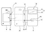
一方、本発明の他の実施形態によれば、前記透視部20は、図3Aに示すように、前記表示画面Pと同じ大きさを有する。 Meanwhile, according to another embodiment of the present invention, the see-through
このように、透視部20が表示画面Pの全領域に対応して広い面積を有する場合には、モバイル機器Mの表示画面Pに表示内容の全体が正常に表示可能になるので、ユーザは、保護カバー10を開かなくても表示画面Pを見ながら内容を確認することが可能になるが、この詳細については後述する。 Thus, when the
また、本発明のさらに他の実施形態によれば、前記保護カバー10は、図2C及び図3Bに示すように、前記モバイル機器Mの背面に取り付けられている既存の背面カバーをはずした後にさらに取り付ける取付カバー30を備える。 In addition, according to another embodiment of the present invention, the
また、前記取付カバー30と保護カバー10は連結部材40によって連結されることにより、保護カバー10は連結部材40によって回転しながら表示画面Pの上に覆われたり、これとは逆に、開かれる動作を行うことになる。このとき、前記保護カバー10が前記表示画面Pに覆われた状態では、前記表示画面Pが保護され、透視部20を介して表示画面Pの内容を見ることが可能になる。 The mounting
すなわち、図2C及び図3Bに示すように、保護カバー10の開閉作動のために、保護カバー10の一方の側には、軟質の合成樹脂や高周波融着可能な生地が重ねられた連結部材40が配設される。 That is, as shown in FIG. 2C and FIG. 3B, for opening and closing operation of the
また、このように、連結部材40は、取付カバー30と保護カバー10を連結するので、モバイル機器に取り付けられた状態でユーザが前記保護カバー10を開閉する動作によって前記表示画面Pを開閉する。 In addition, since the connecting
特に、本発明の保護カバー10には透視部20が設けられているので、表示画面Pの内容を保護カバー10を開かなくても確認することが可能になり、既存の保護カバー10を用いる場合よりも開閉頻度が減る結果、長時間に亘って使用可能になるという卓越した効果を発揮する。 In particular, since the
また、図5に示すように、後述する保護カバー10は、外側部材50と内側部材51を備え、内部に補強部材60が配設された場合には、前記開口部11の内周縁部が高周波融着されるようになっている。 As shown in FIG. 5, the
このような構成においては、前記透視部材21の固定部23の内側面が段付き状に形成されて段差部24が設けられ、この段差部24には両面テープなどの貼合部材52が配設される。 In such a configuration, the inner surface of the fixing
このため、前記透視部材21は、前記貼合部材52によって前記開口部11の内周面に組み付けられる。 For this reason, the see-through
このような構成によれば、保護カバー10を完成した後に、開口部11に透視部材21を取り付けることにより、様々な材質を有する透視部材21を選択的に保護カバー10のデザインに合わせて取り付けることができる。 According to such a configuration, after the
さらに、透視部20を仕上げるための上述した透視部材21は、好ましくは、導電性機能を有する透明または半透明の合成樹脂から製作されてもよく、このような透視部材21は射出成形によって製作されてもよく、高透明度及び高強度の薄肉のPC材質の板材に機械加工を施して製作してもよい。 Further, the above-described see-through
特に、図1Bに示すように、透視部材21と固定部23を一体に形成してもよいが、保護カバー10を、後述するように、高周波融着可能な生地から製作する場合には、生地の間に別途の補強部材60を挟持することなく透視画面部22から固定部23が板状に延出して補強部材60の役割を代わりに担ってもよい。 In particular, as shown in FIG. 1B, the see-through
このような構成によれば、補強部材60が不要になるので、固定部23に高周波融着可能な生地状の外側部材50と内側部材51を貼合部材52を用いて固定部23の両面に直接的に貼り付けて一体に製造することができるので、製造工数及びコストが削減されるという効果が得られる。 According to such a configuration, since the reinforcing
また、前記透視部材21は、強化ガラスまたはハーフミラーから製作されてもよいが、強化ガラスは、PC材質よりもその透明度が良好であり、保護カバー10に適用する場合に高級感が得られる。 The see-through
さらに、透視部材21をハーフミラーから製作する場合に、表示画面Pに光が発光しない状態では、鏡の機能を提供して、ユーザが別途の鏡を携行しなくても、鏡の代わりに使用可能であるという付加的な効果が得られ、モバイル機器が駆動されるときには、表示画面Pに光が発光されて、表示画面Pに表示される主な情報をハーフミラーを介して手軽に確認することが可能になる。 Further, when the
さらに、PC材質または強化ガラス及びハーフミラーには導電性機能を持たせることにより、保護カバー10を閉じた状態でも表示画面Pをタッチしながら一部の機能を操作することができて、ユーザは、保護カバー10を開かなかった状態で表示画面Pの内容を確認したり、タッチ機能を操作したりできる。 Further, by providing the PC material or tempered glass and the half mirror with a conductive function, some functions can be operated while touching the display screen P even when the
このような構成を有する本発明の保護カバー10に配設される透視部材21は、本発明のさらに他の実施形態によれば、前記表示画面Pに表示される主な情報Fまたは表示内容の位置及びその外周の大きさに対応するように保護カバー10の前面部に種々に形成可能である。 According to still another embodiment of the present invention, the see-through
すなわち、表示画面Pに表示される主な情報Fは、横方向または縦方向に表示されることが一般的である。 That is, the main information F displayed on the display screen P is generally displayed in the horizontal direction or the vertical direction.
このために、本発明に係る透視部材21は、一実施形態によれば、図1Aに示すように、前記保護カバー10に対して横方向に形成されてもよく、他の実施形態によれば、前記透視部材21は、図2A及び図6に示すように、前記保護カバー10に縦方向に長尺に形成されてもよい。 For this reason, according to one embodiment, the see-through
また、本発明のさらに他の実施形態によれば、前記透視部材21は、前記保護カバー10に横方向または縦方向に形成されるが、図2Aに示すように、片側に偏って形成されてもよい。 In addition, according to still another embodiment of the present invention, the see-through
このように、本発明に係る透視部材21は、モバイル機器の表示画面Pに表示される主な情報Fの配列形態に対応して横方向または縦方向の配置形態を有するデザインを採用してもよく、保護カバー10の一方の周縁部に偏っている配置形態を有するデザインを採用してもよい。 Thus, even if the
これにより、ユーザは、モバイル機器メーカごとに異なる形の表示画面Pの主な情報Fの配列形態に応じて本発明の保護カバー10を選定して使用することが可能になるので、種々の配置形態を有する保護カバー10の透視部材21が適用された本発明によれば、ユーザの使い勝手がよくなる。 Accordingly, the user can select and use the
一方、上述した前記固定部23は、本発明のさらに他の実施形態によれば、図2Cに示すように、前記透視部材21を除く保護カバー10の残りの領域に延設され、前記固定部23の両側面には、外側部材50と内側部材51が貼合部材52によって一体に貼り合わせられている。 On the other hand, according to still another embodiment of the present invention, the fixing
さらに、本発明のさらに他の実施形態によれば、前記固定部23と前記外側部材50及び内側部材51の間には、補強部材60がさらに配設されていてもよい。 Furthermore, according to still another embodiment of the present invention, a reinforcing
これは、保護カバー10が高周波融着または超音波融着可能な生地から製作される場合、または融着不可能な生地から製作される場合に、生地の内側面に高周波と反応する熱可塑性接着フィルムまたは接着層を形成して高周波と反応しない生地から保護カバー10を形成する場合のための構成である。 This is because, when the
すなわち、図2Cまたは図3Bに示すように、透視部材21が縦方向または横方向に保護カバー10の外周縁または中央に配設され、その残りの部分が一体に延設されて固定部23を構成してもよい。 That is, as shown in FIG. 2C or FIG. 3B, the see-through
この場合、外側部材50と内側部材51が生地製であり、その生地の間に別途の補強部材60などをさらに介装しなくてもよい。 In this case, the
すなわち、前記固定部23が前記補強部材60の代わりに生地の間に配設され、前記補強部材60は前記貼合部材52によって外側部材50及び内側部材51と貼り合わせられて保護カバー10を形成する。 That is, the fixing
一方、本発明のさらに他の実施形態によれば、図3Aに示すように、前記保護カバー10は、前記表示画面Pの外周に沿って周縁部12が形成される。 Meanwhile, according to still another embodiment of the present invention, as shown in FIG. 3A, the
前記透視部材21は、前記表示画面Pと対応する大きさを有し、前記周縁部12の領域内に外部に露出されるように形成される。 The see-through
上述した実施形態においては、透視部20が主な情報Fを表示するために保護カバー10の一部に形成されることを想定しており、これに対し、この実施形態においては、表示画面Pの全面積と同じ大きさに透視部20が形成されることを想定している。これにより、この実施形態においては、透視部材21を保護カバー10に組み付けるために周縁部12が形成されている。 In the above-described embodiment, it is assumed that the
このため、透視部材21の固定部23は、4面の周縁部に形成され、この固定部23は、前記周縁部12に挿設される。 For this reason, the fixing
このような構成によれば、透視部材21を用いて、表示画面Pの全体内容を保護カバー10を開くことなく確認することが可能になる。 According to such a configuration, it is possible to check the entire contents of the display screen P using the
加えて、前記透視部材21を用いて、前記モバイル機器のボタンを押して表示画面Pをオンにした後に、外部から表示画面Pをタッチ操作しながら使用することが可能になる。 In addition, after the display device P is turned on by pressing the button of the mobile device using the see-through
要するに、ユーザは、保護カバー10を頻繁に開くことなく、表示画面Pの内容を確認し、タッチ操作しながら便利に使用することが可能になる。 In short, the user can check the contents of the display screen P without opening the
また、保護カバー10が表示画面Pを保護していることから、外部の衝撃によって傷付きが発生せず、これにより、高価な保護フィルムを貼り付けなかった状態でも表示画面Pに傷付きを生じることなく長期に亘って使用することが可能になるという効果が得られる。 Further, since the
一方、本発明のさらに他の実施形態によれば、前記保護カバー10には、前記携帯用のモバイル機器Mの前面部に配設された機能部品に対応する位置に機能孔13が穿設される。 On the other hand, according to still another embodiment of the present invention, the
これにより、本発明に係る保護カバー10の周縁部には、前記機能孔13が必ず配設されることが好ましい。 Accordingly, it is preferable that the
このような前記機能孔13は、例えば、通話スピーカー孔14と、正面カメラ孔15と、ユーザ認識孔16及び調光センサ孔17の選択的な組み合わせからなる。 The
併せて、前記保護カバー10の一方の側には、前記携帯用のモバイル機器Mの機能ボタン部またはタッチボタン部に対応する位置に押下ボタン表示部18がさらに形成されてなる。 In addition, a
このような構成によれば、保護カバー10が覆われた状態でモバイル機器の正面の上下端部に配設された通話スピーカー、正面カメラ、ユーザ認識センサ、調光センサなどが前記機能孔13を介して外部に露出されるので、保護カバー10が覆われた状態でもそれぞれの機能が正常に発揮される。 According to such a configuration, a call speaker, a front camera, a user recognition sensor, a dimming sensor, and the like disposed at the upper and lower ends of the front surface of the mobile device in a state where the
特に、押下ボタン表示部18は、保護カバー10が覆われた状態でモバイル機器の下端に設けられる押下ボタンを操作するときに、ボタンの位置を保護カバー10が覆われた状態でも確認しやすいようになっている。 In particular, when the push
これは、モバイル機器メーカーごとに機能部品の配置形態が異なることや、前記機能以外の付加的な機能を有する部品が追加または削減されることを考慮にいれて保護カバー10を製作するためである。 This is because the
また、本発明のさらに他の実施形態によれば、前記透視部材21は、前記保護カバー10に埋設されるが、その底面部が前記表示画面Pに接触しないように微隙間Dを維持して埋設される。 Further, according to still another embodiment of the present invention, the see-through
すなわち、本発明の保護カバー10を取り付けて使用すると、既存に保護カバー10なしにモバイル機器を用いるときと同様に、保護フィルムを貼り付けて用いなくても表示画面Pを十分に保護することが可能になる。 That is, when the
しかしながら、透視部材21の材質が透明の合成樹脂、強化ガラスまたはハーフミラーである場合に、透視部材21の硬度が表示画面Pと同じ硬度を有するため、保護カバー10を開閉するときに透視部材21が表示画面Pにぶつかって傷つきや衝撃が加えられることがある。 However, when the material of the see-through
これにより、本発明においては、上記の問題を予防するために、図7に示すように、透視部材を保護カバー10に組み付けるときに、透視部材21の底面部が表示画面Pに接触しないように微隙間Dを維持した状態で組み付ける。 Accordingly, in the present invention, in order to prevent the above problem, as shown in FIG. 7, when the fluoroscopic member is assembled to the
このように透視部材21の底面は表示画面Pと微間隔を維持するため、保護カバー10が表示画面Pに覆われるときに直接的に接触しなくなり、前記表示画面Pには、主としてベルベットやスウェードなどの柔らかな触感を有する生地製の保護カバー10の内側部材51が直接的に接触するので、傷つきが全く発生しない。 In this way, the bottom surface of the see-through
一方、本発明のさらに他の実施形態によれば、透視部20を有する保護カバー10をモバイル機器に取り付けるときに、その取付有無が確認可能なように構成される。 On the other hand, according to still another embodiment of the present invention, when the
すなわち、図8に示すように、上述したように、本発明の保護カバー10は、前記モバイル機器Mの背面に取り付けられている既存の背面カバーをはずした後にさらに取り付けられる取付カバー30が配設されて、この取付カバー30と連結部材40によって連結されることにより、前記表示画面Pを保護するようになっている。 That is, as shown in FIG. 8, as described above, the
このため、既存の背面カバーをはずした後に取付カバー30を前記モバイル機器Mの背面に取り付けると、これをモバイル機器が感知するようにモバイル機器の背面の一方の側に取付感知部70が配設される。 For this reason, when the
また、取付カバー30の内側面には、前記取付感知部70が取付カバー30の取付有無を認識するように取付認識部80が配設される。 An
このような取付認識部80は、前記取付感知部70と機構的に接続される接触式に構成されてもよく、取付認識部80と間隔を維持した状態で接続されるように非接触式に構成されてもよい。 The
前記取付認識部80が接触式に構成される場合には、種々の形態が採用可能であるが、例えば、前記取付感知部70がマイクロスイッチまたはタクトスイッチなどから構成され、前記取付認識部80は取付カバー30の内面に突設される押下突起状に構成されてもよく、この場合、背面カバーには押下突起がなく、取付カバー30の取り付け状態を認識するように構成される。 When the
さらに、前記取付認識部80が非接触式に構成される場合には、例えば、前記取付感知部70がフォトセンサまたは磁気センサセンサなどから構成されてもよく、前記取付認識部80は、フォトセンサの光を遮断または通過させる遮断片または磁気センサセンサと連動する金属材質の磁性体から構成されてもよい。 Further, when the
このため、モバイル機器の背面カバーをはずした後に取付カバー30を取付すると、押下突起、遮断片または金属の磁性体がスイッチ、フォトセンサまたは磁気センサセンサを作動させることにより、モバイル機器においては、保護カバー10が配設された取付カバー30の取付有無を電気的に認識することになる。 For this reason, when the
本発明は、このために、前記取付カバー30が取付されているときには、携帯用のモバイル機器Mの表示画面Pに表示される主な情報Fが前記保護カバー10の透視部材21の領域にのみ表示されるように構成されてもよい。 For this reason, according to the present invention, when the mounting
すなわち、前記保護カバー10の透視部材21の画面領域に相当する分の主な情報Fを表示画面Pに表示することになる。 That is, the main information F corresponding to the screen area of the see-through
このとき、透視部材21は、上述したように、保護カバー10の前面部の一部に形成されて主な内容Fのみを表示するか、あるいは、前面部のサイズと同じ面積を有して表示画面Pの全体内容を表示することになる。 At this time, as described above, the see-through
このため、ユーザは、透視部材21を介して表示画面P主な情報Fを確認しながら保護カバー10を開かなかった状態でも外部から透視部材21の表面をタッチ操作しながらモバイル機器を便利に操作することが可能になる。 For this reason, the user can conveniently operate the mobile device while touching the surface of the
一方、本発明のさらに他の実施形態によれば、保護カバー10の取付有無を感知するとともに、保護カバー10の開閉状態を感知するための開閉有無感知手段110がさらに配設される。 Meanwhile, according to another embodiment of the present invention, an opening / closing presence / absence detecting means 110 for detecting whether the
すなわち、図9及び図10に示すように、前記保護カバー10には、前記表示画面Pに保護カバー10が覆われているか否かを判別する感知手段110が内蔵される。 That is, as shown in FIGS. 9 and 10, the
このために、前記モバイル機器の背面には、回路接続部130が設けられるが、前記感知手段110は、前記回路接続部130と電気的に接続される。 For this purpose, a
前記取付カバー30には接続端子部120が内蔵されて、この接続端子部120が前記回路接続部130と有線または無線にて開閉状態の信号を送受信しながら前記モバイル機器Mの内部の制御回路部と相互連動して保護カバー10の開閉状態に応じて前記表示画面Pをオンまたはオフにする。 The attachment cover 30 includes a
このような構成によれば、前記保護カバー10の取付有無を判断する取付感知部70と前記感知手段が有機的に連動される。 According to such a configuration, the
すなわち、保護カバー10を取り付けるためにモバイル機器の背面カバーをはずした後に取付カバー30を取付すれば、取付認識部80及び取付感知部70によってモバイル機器は、保護カバー10を有する取付カバー30が取付されたことを認知する。 That is, if the
また、保護カバー10の種類によって、モバイル機器は、透視部材21の大きさに応じて、透視部材21が居部的な大きさを有するものであるか、それとも、表示画面Pと同じ大きさを有するものであるかが認知可能なようにモバイル機器の内部プログラムにおいて制御するように構成されてもよい。 In addition, depending on the type of the
このため、モバイル機器は、表示画面Pに主な情報Fを透視部材21の大きさに合わせて表示するので、ユーザは、外部から透視部材21の表面に直接的にタッチ操作することが可能になる。 For this reason, the mobile device displays the main information F on the display screen P according to the size of the
また、保護カバー10が前記表示画面Pの上に覆われた状態では、保護カバー10に内蔵された感知手段110がこれを感知して、接続端子部120と回路接続部130を介してモバイル機器に保護カバー10が覆われているか否かを認識させる。 In the state where the
この状態で、モバイル機器に文字や留守番電話が受信されると、モバイル機器は、表示画面Pに保護カバー10が覆われていない状態では表示画面Pに正常な内容を表示し、表示画面Pに保護カバー10が覆われている状態を認識した場合には透視部材21の領域にのみ主な情報Fを表示する。 In this state, when a character or an answering machine is received by the mobile device, the mobile device displays normal content on the display screen P in a state where the
このように、本発明に係る保護カバー10は、モバイル機器と連動して保護カバー10の取付有無を取付カバー30を介してモバイル機器に認識させ、その後には、保護カバー10が表示画面Pに覆われている状態を感知して表示画面Pには透視部材21の大きさに合わせて主な情報Fを表示するようになっている。 Thus, the
このため、本発明の保護カバー10は、モバイル機器の表示画面Pを安全に保護する役割しかしなかった既存の保護カバー10とは異なり、表示画面Pの上に覆われた状態でもタッチ操作しながら使用可能になるという卓越した効果が得られる。 For this reason, the
本発明のさらに他の実施形態によれば、上述した感知手段110は、磁気センサ、照度センサ、フォトセンサまたは近接センサであってもよい。 According to still another embodiment of the present invention, the
すなわち、保護カバー10に内蔵される感知手段110がフォトセンサまたは照度センサである場合には、表示画面Pの光を感知して保護カバー10が覆われた状態を感知させ、保護カバー10に内蔵される感知手段110が近接センサである場合には、表示画面Pと保護カバー10との距離を感知して保護カバー10が覆われた状態を感知させる。 That is, when the sensing means 110 built in the
また、保護カバー10に内蔵される感知手段110が磁気センサである場合には、モバイル機器の表示画面Pの周りに磁気センサと連動する磁性体などを設けて、保護カバー10と連動して保護カバー10の開閉有無を感知するように構成してもよい。 In addition, when the sensing means 110 built in the
このように保護カバー10に取り付けられる感知手段110は、そのセンサの種類及び方式に応じて、保護カバー10そのものを既存のモバイル機器の仕様を変更することなく適用することができ、モバイル機器メーカーが直接的に保護カバー10を互換性よく製造する場合には、保護カバー10とモバイル機器とが相互連動するように構成してもよいということはいうまでもない。 As described above, the sensing means 110 attached to the
一方、本発明のさらに他の実施形態によれば、前記感知手段110を保護カバー10の内部に実装するための構成要素をも提供する。 Meanwhile, according to another exemplary embodiment of the present invention, a component for mounting the
このために、図4A及び図4Bに示すように、前記保護カバー10は、外側部材50と、内側部材51とからなり、前記透視部材21は、透視画面部22と、この透視画面部22の周縁部に形成される固定部23とからなる。 For this purpose, as shown in FIGS. 4A and 4B, the
さらに、前記固定部23は、前記外側部材50と内側部材51との間に挟持される。 Further, the fixing
前記外側部材50と内側部材51は、高周波融着または超音波融着可能な生地から製作される場合には、その間には保護カバー10を板状にするための合成樹脂材質の補強部材60がさらに配設される。 In the case where the
また、前記固定部23は、前記補強部材60の内部に挿入された状態で固定される。 Further, the fixing
すなわち、本発明のさらに他の実施形態によれば、前記補強部材60は、合成樹脂製の第1の補強板61及び第2の補強板62から構成されてもよい。 That is, according to still another embodiment of the present invention, the reinforcing
前記第1の補強板61と第2の補強板62との間には、前記固定部23が収容可能な載置部63が設けられ、この載置部63に前記固定部23が収容されて貼合部材52によって貼り合わせられる。 Between the first reinforcing
さらに、前記載置部63の内側には、前記開口部11と介するように形成された透視ウィンドウ64を介して前記透視画面部22が外部に露出されることにより、透視部材21を有する保護カバー10が完成される。 Further, a protective cover having a see-through
さらにまた、本発明のさらに他の実施形態によれば、前記第1の補強板61と第2の補強板62、前記載置部63と固定部23は、それぞれ貼合部材52によって貼り合わせられる。 Furthermore, according to still another embodiment of the present invention, the first reinforcing
これは、補強部材60と透視部材21を板状にするためであり、また、前記外側部材50と内側部材51は、前記第1の補強板61と第2の補強板62の各外側面に前記貼合部材52によって貼り付けられて薄肉の保護カバー10が得られるようにすることが好ましい。 This is to make the reinforcing
前記外側部材50は、外部に露出されるものであるため、衝撃や傷付きに強く、様々なカラー及び模様を有する高周波融着可能な生地から製作される。 Since the
前記内側部材51は、表示画面Pに接触されるものであるため、ベルベットやスウェードなど表示画面Pと接触されたときに表示画面Pに傷付きを与えない柔らかな生地から製作される。 Since the
また、本発明のさらに他の実施形態によれば、上述した感知手段110が保護カバー10に取り付けられる場合に、感知手段110と、取付カバー30及び連結部材40を介して電気的に連結するためのフレキシブルプリント基板(FPCB)100が収容される。 According to still another embodiment of the present invention, when the sensing means 110 described above is attached to the
このために、前記載置部63の一方の側には、フレキシブルプリント基板(FPCB)100が収容される収容溝65がさらに形成される。 For this purpose, an
前記収容溝65は、フレキシブルプリント基板(FPCB)100の連結経路に沿って形成され、その深さと幅は、フレキシブルプリント基板(FPCB)100の厚さと幅に合わせて形成され、フレキシブルプリント基板(FPCB)100の両側面または第1の補強板61と第2の補強板62の収容溝65には両面接着テープなどの貼合部材52が配設される。 The receiving
前記フレキシブルプリント基板(FPCB)100の一方の端には、前記補強部材60に内蔵されて保護カバー10が表示画面Pに覆われた状態を感知するための感知手段110が配設される。 At one end of the flexible printed circuit board (FPCB) 100, sensing means 110 for sensing a state in which the
前記感知手段110が保護カバー10に内蔵されるために、第1の補強板61と第2の補強板62との間に別途の感知手段110の収納空間が形成される。 Since the sensing means 110 is built in the
また、フレキシブルプリント基板(FPCB)100の収容溝65は、前記感知手段110の収納空間と連通される。 The
さらに、フレキシブルプリント基板(FPCB)100の途中部は、保護カバー10の一方の端部と連結される連結部材40の内部に引き込まれるように構成される。 Furthermore, the intermediate portion of the flexible printed circuit board (FPCB) 100 is configured to be drawn into the connecting
前記フレキシブルプリント基板(FPCB)100の他方の端は、前記連結部材40と連結されてモバイル機器の取付カバー30の内側に設けられる接続端子部120と連結されるが、この接続端子部120が前記携帯用のモバイル機器Mの背面に設けられた回路接続部130と接続されることにより、保護カバー10が表示画面Pに覆われている状態に応じて前記表示画面Pをオンまたはオフにする。 The other end of the flexible printed circuit board (FPCB) 100 is connected to the connecting
この実施形態において説明した前記感知手段110は、上述したように、磁気センサ、照度センサ、フォトセンサまたは近接センサであってもよく、それぞれのセンサによって、保護カバー10と取付カバー30の作動に対応して表示画面に表示される主な情報Fは、透視部材21を介して確認可能であるということはいうまでもない。 As described above, the
本発明のさらに他の実施形態は、携帯用のモバイル機器の背面カバーをはずしてモバイル機器と連結される必要なしに、保護カバーの開閉だけでモバイル機器と連動されるモバイル機器用の保護カバーを提供する。 Still another embodiment of the present invention provides a protective cover for a mobile device that is linked to the mobile device by simply opening and closing the protective cover without having to remove the back cover of the portable mobile device and connect to the mobile device. provide.
一般に、携帯用のモバイル機器の背面カバーをはずして連結することは、モバイル機器とモバイル機器用の保護カバーの見栄え(一体感)を向上させるというメリットがあるが、取り外しの煩雑さがあり、電子的な制御手段を多数備える場合に駆動上の問題を引き起こす余地がある。 In general, removing and connecting the back cover of a portable mobile device has the advantage of improving the appearance of the mobile device and the protective cover for the mobile device (a sense of unity). There is room for driving problems when many control means are provided.
このため、上記の背面カバーをはずすことなく、モバイル機器の表面にモバイル機器用の保護カバーを取り付けて表示画面Pの上に覆われた状態を認識可能にする実施形態を提供する。 Therefore, an embodiment is provided in which a protective cover for a mobile device is attached to the surface of the mobile device and the state covered on the display screen P can be recognized without removing the back cover.
この実施形態において、携帯用のモバイル機器は、保護カバー10が前記表示画面Pの上に覆われた状態では、保護カバーの透視部20と対応する表示画面Pの一部に主な情報Fを表示するために保護カバー10の開閉を認識可能な感知手段を備える。 In this embodiment, in the portable mobile device, when the
モバイル機器用の保護カバーは、前記携帯用のモバイル機器に取り付けられて連動される。 A protective cover for a mobile device is attached to and interlocked with the portable mobile device.
モバイル機器用の保護カバーは、前記モバイル機器Mが駆動されたときに、前記表示画面Pに表示される主な情報Fを前記保護カバー10が前記表示画面Pの上に覆われた状態で確認する透視部20が配設された保護カバー10を備え、前記保護カバー10は、連結部材40を介して前記モバイル機器Mの背面に取り付けられる取付カバー30と連結されて前記表示画面Pを開閉することができる。 The protective cover for the mobile device confirms main information F displayed on the display screen P in a state where the
前記携帯用のモバイル機器に含まれている前記感知手段は、磁気センサ、静電センサ、定圧センサ、電気接触センサのうちのいずれか一種であってもよい。 The sensing means included in the portable mobile device may be any one of a magnetic sensor, an electrostatic sensor, a constant pressure sensor, and an electrical contact sensor.
一般に、前記感知手段として磁気センサまたは電気接触センサを採用することが好ましい。 In general, it is preferable to employ a magnetic sensor or an electrical contact sensor as the sensing means.
この場合、前記保護カバー10は、磁気的な信号を送信するためのマグネチック材料または電気的な信号を送信するための伝導性材料をさらに含み、これらの材料が含まれている保護カバー10が表示画面Pの上に覆われる場合に、保護カバー10に含まれているマグネチック材料や伝導性材料が感知手段によって感知されて保護カバー10が表示画面Pの上に覆われている状態をモバイル機器Mに知らせることになる。 In this case, the
また、保護カバー10が表示画面Pの上に覆われている状態をモバイル機器に認識させることに加えて、保護カバー10が表示画面Pの上に覆われている状態に応じて、モバイル機器の表示画面Pをオンまたはオフにする実施形態も提供可能である。 Further, in addition to making the mobile device recognize the state in which the
図11を参照すると、本発明のさらに他の実施形態において、モバイル機器は、保護カバー10が表示画面Pの上に覆われている状態を感知する。 Referring to FIG. 11, in another embodiment of the present invention, the mobile device detects a state in which the
保護カバーが表示画面Pの上に覆われていると認識される場合に、通話を着信する場合に、着信された通話情報を予め設定された表示画面Pの一部に表示する。 When it is recognized that the protective cover is covered on the display screen P, when receiving a call, the received call information is displayed on a part of the preset display screen P.
保護カバー10が表示画面Pの上に覆われている場合に、報知情報を着信したときに着信した報知情報を予め設定された表示画面Pの一部に表示する。 When the
このとき、着信情報や時間などの報知情報が表示される表示画面Pの一部は、保護カバーに形成された透視部とマッチングされてユーザにこれを確認させるように設定される。 At this time, a part of the display screen P on which notification information such as incoming call information and time is displayed is set so as to be matched with a fluoroscopic part formed on the protective cover and to be confirmed by the user.
以上の説明は本発明の技術的な思想を例示的に説明したものに過ぎず、本発明が属する技術分野において通常の知識を有する者であれば、本発明の本質的な特性から逸脱しない範囲において種々の修正及び変形が可能である。 The above description is merely illustrative of the technical idea of the present invention, and a person who has ordinary knowledge in the technical field to which the present invention belongs does not depart from the essential characteristics of the present invention. Various modifications and variations are possible.
よって、本発明に開示された実施形態は、本発明の技術思想を限定するためのものではなく、単に説明するためのものであり、これらの実施形態によって本発明の技術思想の範囲が限定されることはない。本発明の保護範囲は、下記の請求範囲によって解釈さるべきであり、それと同じ範囲内にあるあらゆる技術思想は、本発明の権利範囲に含まれるものと解釈さるべきである。 Therefore, the embodiments disclosed in the present invention are not intended to limit the technical idea of the present invention, but merely to explain them, and the scope of the technical idea of the present invention is limited by these embodiments. Never happen. The protection scope of the present invention should be construed by the following claims, and all technical ideas within the same scope should be construed as being included in the scope of the present invention.
10 保護カバー
11 開口部
12 周縁部
13 機能孔
14 通話スピーカー孔
15 正面カメラ孔
16 ユーザ認識孔
17 調光センサ孔
18 押下ボタン表示部
20 透視部
21 透視部材
22 透視画面部
23 固定部
24 段差部
30 取付カバー
40 連結部材
50 外側部材
51 内側部材
52 貼合部材
60 補強部材
61 第1の補強板
62 第2の補強板
63 載置部
64 透視ウィンドウ
65 収容溝
70 取付感知部
80 取付認識部
100 フレキシブルプリント基板(FPCB)
110 感知手段
120 接続端子部
130 回路接続部
M モバイル機器
P 表示画面
F 主な情報
D 微隙間
DESCRIPTION OF
DESCRIPTION OF
110 sensing means 120
Claims (31)
Translated fromJapanese前記保護カバーは、前記モバイル機器が駆動されるときに、前記表示画面に表示される主な情報を前記保護カバーが前記表示画面の上に覆われた状態で確認するための透視部を備えることを特徴とするモバイル機器用の保護カバー。In a protective cover for protecting the display screen of a portable mobile device,
The protective cover includes a fluoroscopic unit for confirming main information displayed on the display screen in a state where the protective cover is covered on the display screen when the mobile device is driven. A protective cover for mobile devices.
前記取付カバーが取り付けられるときには、携帯用のモバイル機器の表示画面に表示される主な情報が前記保護カバーの透視部材の領域にしか表示されないことを特徴とする請求項4に記載のモバイル機器用の保護カバー。An attachment sensing unit is disposed on one side of the back surface of the portable mobile device, and the attachment sensing unit is connected to an attachment recognition unit disposed on the attachment cover in a contact or non-contact manner. By recognizing whether or not the protective cover is attached,
5. The mobile device according to claim 4, wherein when the mounting cover is attached, main information displayed on a display screen of the portable mobile device is displayed only in a region of the see-through member of the protective cover. Protective cover.
前記モバイル機器が駆動されるときに、前記表示画面に表示される主な情報を前記保護カバーが前記表示画面の上に覆われた状態で確認するための透視部を有する保護カバーを備え、
前記保護カバーは、連結部材を介して前記モバイル機器の背面に取り付けられる取付カバーと連結されて前記表示画面を開閉することを特徴とするモバイル機器用の保護カバー。Sensing means capable of recognizing opening and closing of the protective cover so that main information can be displayed on a part of the display screen corresponding to the fluoroscopic part of the protective cover when the protective cover is covered on the display screen. In the protective cover for mobile devices linked with portable mobile devices,
A protective cover having a fluoroscopic part for confirming main information displayed on the display screen in a state where the protective cover is covered on the display screen when the mobile device is driven;
The protective cover for a mobile device is connected to a mounting cover attached to the back surface of the mobile device through a connecting member to open and close the display screen.
前記モバイル機器が駆動されるときに、前記表示画面に表示される主な情報を前記保護カバーが前記表示画面の上に覆われた状態で確認するための透視部を有する保護カバーを備え、
前記保護カバーは、連結部材を介して前記モバイル機器の背面に取り付けられる取付カバーと連結されて前記表示画面を開閉し、
保護カバーの開閉有無に応じてモバイル機器の表示画面をオンまたはオフにすることを特徴とするモバイル機器用の保護カバー。Sensing means capable of recognizing opening and closing of the protective cover so that main information can be displayed on a part of the display screen corresponding to the fluoroscopic part of the protective cover when the protective cover is covered on the display screen. In the protective cover for mobile devices linked with portable mobile devices,
A protective cover having a fluoroscopic part for confirming main information displayed on the display screen in a state where the protective cover is covered on the display screen when the mobile device is driven;
The protective cover is connected to a mounting cover attached to the back of the mobile device via a connecting member to open and close the display screen,
A protective cover for a mobile device, wherein the display screen of the mobile device is turned on or off depending on whether the protective cover is opened or closed.
Applications Claiming Priority (4)
| Application Number | Priority Date | Filing Date | Title |
|---|---|---|---|
| KR10-2012-0123733 | 2012-11-02 | ||
| KR20120123733 | 2012-11-02 | ||
| KR1020130053090AKR20140057462A (en) | 2012-11-02 | 2013-05-10 | Protective cover for mobile devices |
| KR10-2013-0053090 | 2013-05-10 |
Publications (1)
| Publication Number | Publication Date |
|---|---|
| JP2014093770Atrue JP2014093770A (en) | 2014-05-19 |
Family
ID=50888229
Family Applications (1)
| Application Number | Title | Priority Date | Filing Date |
|---|---|---|---|
| JP2013133453APendingJP2014093770A (en) | 2012-11-02 | 2013-06-26 | Protection cover for mobile device |
Country Status (2)
| Country | Link |
|---|---|
| JP (1) | JP2014093770A (en) |
| KR (1) | KR20140057462A (en) |
Cited By (10)
| Publication number | Priority date | Publication date | Assignee | Title |
|---|---|---|---|---|
| JP2014137824A (en)* | 2013-01-16 | 2014-07-28 | Samsung Electronics Co Ltd | Mobile device and method for displaying information |
| WO2016039531A1 (en)* | 2014-09-11 | 2016-03-17 | Samsung Electronics Co., Ltd. | Electronic device and control method thereof |
| JP2016062615A (en)* | 2014-09-19 | 2016-04-25 | エルジー エレクトロニクス インコーポレイティド | Mobile terminal and control method therefor |
| KR101624161B1 (en) | 2014-06-27 | 2016-05-25 | 삼성전자주식회사 | Portable terminal device and method for controlling the portable terminal device thereof |
| JP2016100890A (en)* | 2014-11-21 | 2016-05-30 | ホワイトストーン カンパニーリミテッドWhitestone Co., Ltd. | Protector for portable electronic devices |
| JP2016136668A (en)* | 2015-01-23 | 2016-07-28 | アルプス電気株式会社 | Portable electronic devices |
| JP2017004276A (en)* | 2015-06-11 | 2017-01-05 | エルジー ディスプレイ カンパニー リミテッド | Cover case for mobile devices |
| JP2017108606A (en)* | 2015-09-30 | 2017-06-15 | アップル インコーポレイテッド | Case for charging and holding portable listening device |
| WO2018128318A1 (en)* | 2017-01-04 | 2018-07-12 | 삼성전자 주식회사 | Cover and electronic device having same |
| US10470538B2 (en) | 2014-06-27 | 2019-11-12 | Samsung Electronics Co., Ltd. | Portable terminal and display method thereof |
Families Citing this family (11)
| Publication number | Priority date | Publication date | Assignee | Title |
|---|---|---|---|---|
| KR102293482B1 (en)* | 2014-05-30 | 2021-08-26 | 삼성전자주식회사 | Electronic device and method for user interface in electronic device and cover of electronic device |
| KR102219839B1 (en)* | 2014-08-11 | 2021-02-24 | 삼성전자주식회사 | A cover device for an electronic device |
| KR101700765B1 (en)* | 2014-08-12 | 2017-01-31 | 엘지전자 주식회사 | Mobile terminal and mehtod of conrtolling the same |
| KR102264444B1 (en)* | 2014-09-04 | 2021-06-15 | 삼성전자주식회사 | Method and apparatus for executing function in electronic device |
| KR101579887B1 (en)* | 2014-10-16 | 2015-12-23 | 유석근 | Protective Cases for mobile devices with a secondary display |
| KR101651033B1 (en) | 2015-01-08 | 2016-08-24 | 엘지전자 주식회사 | Terminal and operating method thereof |
| US10623957B2 (en) | 2015-04-21 | 2020-04-14 | Graham Dugoni | System and apparatus for selectively limiting user control of an electronic device |
| US9735747B2 (en)* | 2015-07-10 | 2017-08-15 | Intel Corporation | Balancing mobile device audio |
| KR102491404B1 (en) | 2017-12-11 | 2023-01-26 | 삼성디스플레이 주식회사 | display device capable of changing luminance according to operating frequency |
| KR102406807B1 (en) | 2018-01-04 | 2022-06-13 | 삼성디스플레이 주식회사 | Window member |
| CN109168231B (en)* | 2018-08-01 | 2020-06-26 | 广东美的制冷设备有限公司 | Key brightness control method and control device |
Citations (19)
| Publication number | Priority date | Publication date | Assignee | Title |
|---|---|---|---|---|
| JPH10276817A (en)* | 1997-04-05 | 1998-10-20 | Koei:Kk | Case for portable wireless talking unit |
| JPH11196164A (en)* | 1997-12-25 | 1999-07-21 | Matsushita Electric Ind Co Ltd | Case for mobile terminal |
| JP2002051140A (en)* | 2000-05-23 | 2002-02-15 | Lg Electronics Inc | Cellular phone and drive method therefor |
| JP2002185592A (en)* | 2000-12-18 | 2002-06-28 | Matsushita Electric Ind Co Ltd | Foldable mobile phone case |
| JP2003511985A (en)* | 1999-10-08 | 2003-03-25 | ノキア モービル フォーンズ リミテッド | Wireless communication device |
| JP2003511983A (en)* | 1999-10-08 | 2003-03-25 | ノキア モービル フォーンズ リミテッド | Wireless communication device |
| JP2006135979A (en)* | 1996-04-26 | 2006-05-25 | Mitsubishi Electric Corp | Image display device |
| JP2007124001A (en)* | 2005-10-25 | 2007-05-17 | Kyocera Corp | Portable electronic devices |
| JP2008052606A (en)* | 2006-08-25 | 2008-03-06 | Kyocera Corp | Electronics |
| JP3143881U (en)* | 2008-05-28 | 2008-08-07 | 株式会社ユビキタスエンターテインメント | Case for portable information terminal |
| JP2008270862A (en)* | 2007-04-16 | 2008-11-06 | Nissha Printing Co Ltd | Portable apparatus |
| JP3156242U (en)* | 2009-07-06 | 2009-12-24 | 千恵子 松下 | A cover to prevent the display screen from becoming dirty and maintain visibility on the display screen of mobile phones. |
| JP2010016799A (en)* | 2008-06-05 | 2010-01-21 | Brother Ind Ltd | Portable terminal cover |
| JP2010108464A (en)* | 2008-10-29 | 2010-05-13 | K Soft Enterprise Co Ltd | Portable equipment |
| JP2012034065A (en)* | 2010-07-28 | 2012-02-16 | Kyocera Corp | Portable electronic apparatus and inner pressure adjustment mechanism |
| JP3177945U (en)* | 2012-06-13 | 2012-08-23 | 株式会社トレードワークス | Waterproof case |
| JP3177946U (en)* | 2012-06-13 | 2012-08-23 | 株式会社トレードワークス | Waterproof case |
| JP3178403U (en)* | 2012-07-03 | 2012-09-13 | 株式会社レイメイ藤井 | Mobile terminal case for system notebook |
| JP2012182200A (en)* | 2011-02-28 | 2012-09-20 | Asahi:Kk | Waterproof case for electronic apparatus |
- 2013
- 2013-05-10KRKR1020130053090Apatent/KR20140057462A/ennot_activeAbandoned
- 2013-06-26JPJP2013133453Apatent/JP2014093770A/enactivePending
Patent Citations (19)
| Publication number | Priority date | Publication date | Assignee | Title |
|---|---|---|---|---|
| JP2006135979A (en)* | 1996-04-26 | 2006-05-25 | Mitsubishi Electric Corp | Image display device |
| JPH10276817A (en)* | 1997-04-05 | 1998-10-20 | Koei:Kk | Case for portable wireless talking unit |
| JPH11196164A (en)* | 1997-12-25 | 1999-07-21 | Matsushita Electric Ind Co Ltd | Case for mobile terminal |
| JP2003511985A (en)* | 1999-10-08 | 2003-03-25 | ノキア モービル フォーンズ リミテッド | Wireless communication device |
| JP2003511983A (en)* | 1999-10-08 | 2003-03-25 | ノキア モービル フォーンズ リミテッド | Wireless communication device |
| JP2002051140A (en)* | 2000-05-23 | 2002-02-15 | Lg Electronics Inc | Cellular phone and drive method therefor |
| JP2002185592A (en)* | 2000-12-18 | 2002-06-28 | Matsushita Electric Ind Co Ltd | Foldable mobile phone case |
| JP2007124001A (en)* | 2005-10-25 | 2007-05-17 | Kyocera Corp | Portable electronic devices |
| JP2008052606A (en)* | 2006-08-25 | 2008-03-06 | Kyocera Corp | Electronics |
| JP2008270862A (en)* | 2007-04-16 | 2008-11-06 | Nissha Printing Co Ltd | Portable apparatus |
| JP3143881U (en)* | 2008-05-28 | 2008-08-07 | 株式会社ユビキタスエンターテインメント | Case for portable information terminal |
| JP2010016799A (en)* | 2008-06-05 | 2010-01-21 | Brother Ind Ltd | Portable terminal cover |
| JP2010108464A (en)* | 2008-10-29 | 2010-05-13 | K Soft Enterprise Co Ltd | Portable equipment |
| JP3156242U (en)* | 2009-07-06 | 2009-12-24 | 千恵子 松下 | A cover to prevent the display screen from becoming dirty and maintain visibility on the display screen of mobile phones. |
| JP2012034065A (en)* | 2010-07-28 | 2012-02-16 | Kyocera Corp | Portable electronic apparatus and inner pressure adjustment mechanism |
| JP2012182200A (en)* | 2011-02-28 | 2012-09-20 | Asahi:Kk | Waterproof case for electronic apparatus |
| JP3177945U (en)* | 2012-06-13 | 2012-08-23 | 株式会社トレードワークス | Waterproof case |
| JP3177946U (en)* | 2012-06-13 | 2012-08-23 | 株式会社トレードワークス | Waterproof case |
| JP3178403U (en)* | 2012-07-03 | 2012-09-13 | 株式会社レイメイ藤井 | Mobile terminal case for system notebook |
Non-Patent Citations (1)
| Title |
|---|
| DOCOMO STYLE SERIES N−06B 取扱説明書, JPN6014031004, May 2010 (2010-05-01), pages 20 - 21, ISSN: 0002861212* |
Cited By (19)
| Publication number | Priority date | Publication date | Assignee | Title |
|---|---|---|---|---|
| JP2014137824A (en)* | 2013-01-16 | 2014-07-28 | Samsung Electronics Co Ltd | Mobile device and method for displaying information |
| US10671193B2 (en) | 2013-01-16 | 2020-06-02 | Samsung Electronics Co., Ltd. | Mobile device and method for displaying information |
| US10470538B2 (en) | 2014-06-27 | 2019-11-12 | Samsung Electronics Co., Ltd. | Portable terminal and display method thereof |
| KR101624161B1 (en) | 2014-06-27 | 2016-05-25 | 삼성전자주식회사 | Portable terminal device and method for controlling the portable terminal device thereof |
| WO2016039531A1 (en)* | 2014-09-11 | 2016-03-17 | Samsung Electronics Co., Ltd. | Electronic device and control method thereof |
| JP2016062615A (en)* | 2014-09-19 | 2016-04-25 | エルジー エレクトロニクス インコーポレイティド | Mobile terminal and control method therefor |
| JP2016100890A (en)* | 2014-11-21 | 2016-05-30 | ホワイトストーン カンパニーリミテッドWhitestone Co., Ltd. | Protector for portable electronic devices |
| JP2016136668A (en)* | 2015-01-23 | 2016-07-28 | アルプス電気株式会社 | Portable electronic devices |
| JP2017004276A (en)* | 2015-06-11 | 2017-01-05 | エルジー ディスプレイ カンパニー リミテッド | Cover case for mobile devices |
| US10880630B2 (en) | 2015-09-30 | 2020-12-29 | Apple Inc. | Wireless earbud |
| US10681446B2 (en) | 2015-09-30 | 2020-06-09 | Apple Inc. | Earbud case with pairing button |
| JP2017108606A (en)* | 2015-09-30 | 2017-06-15 | アップル インコーポレイテッド | Case for charging and holding portable listening device |
| US10904652B2 (en) | 2015-09-30 | 2021-01-26 | Apple Inc. | Earbud case with insert |
| US11026011B2 (en) | 2015-09-30 | 2021-06-01 | Apple Inc. | Wireless earbud |
| US11026010B2 (en) | 2015-09-30 | 2021-06-01 | Apple Inc. | Portable listening device with sensors |
| US11690428B2 (en) | 2015-09-30 | 2023-07-04 | Apple Inc. | Portable listening device with accelerometer |
| US11944172B2 (en) | 2015-09-30 | 2024-04-02 | Apple Inc. | Portable listening device with sensors |
| WO2018128318A1 (en)* | 2017-01-04 | 2018-07-12 | 삼성전자 주식회사 | Cover and electronic device having same |
| US11503890B2 (en) | 2017-01-04 | 2022-11-22 | Samsung Electronics Co., Ltd. | Cover and electronic device having same |
Also Published As
| Publication number | Publication date |
|---|---|
| KR20140057462A (en) | 2014-05-13 |
Similar Documents
| Publication | Publication Date | Title |
|---|---|---|
| JP2014093770A (en) | Protection cover for mobile device | |
| US20140128131A1 (en) | Protection cover for mobile device | |
| US9112956B2 (en) | Touch screen cover | |
| KR101310757B1 (en) | Mobile terminal | |
| CN204425433U (en) | Mobile terminal | |
| CN106464290B (en) | Mobile electronic device, accessory device therefor, and electronic device including the accessory device | |
| KR100755862B1 (en) | Mobile terminal and display method in mobile terminal | |
| EP3700178B1 (en) | Exterior cover | |
| US9727146B2 (en) | Portable terminal having cover device | |
| CN104375573A (en) | Mobile terminal | |
| CN104811511A (en) | Mobile terminal | |
| CN102006093B (en) | Mobile terminal and method for controlling mobile terminal | |
| US9285829B2 (en) | Mobile terminal | |
| JP5754770B2 (en) | Portable terminal device, program, and display method | |
| KR20150030494A (en) | Protection case for portable device having input key | |
| EP2860616B1 (en) | Touch screen cover | |
| JP2012235431A (en) | Electronic apparatus | |
| CN108521481B (en) | Electronic device | |
| HK1193521A (en) | Protection cover for mobile device | |
| KR100774611B1 (en) | Integrated metal front cover for communication equipment | |
| KR20200056372A (en) | Electronic device with protective case and operating method thereof | |
| KR200467722Y1 (en) | Case for portable terminal | |
| KR102113269B1 (en) | Electronic device with protective case and operating method thereof | |
| KR20090130775A (en) | Touch panel device | |
| JP2024068911A (en) | Protective cover and protective cover set |
Legal Events
| Date | Code | Title | Description |
|---|---|---|---|
| A131 | Notification of reasons for refusal | Free format text:JAPANESE INTERMEDIATE CODE: A131 Effective date:20140729 | |
| A02 | Decision of refusal | Free format text:JAPANESE INTERMEDIATE CODE: A02 Effective date:20150106 |