JP2014093703A - Head mount display, movement detection device, movement detection method and video presentation system - Google Patents
Head mount display, movement detection device, movement detection method and video presentation systemDownload PDFInfo
- Publication number
- JP2014093703A JP2014093703AJP2012244142AJP2012244142AJP2014093703AJP 2014093703 AJP2014093703 AJP 2014093703AJP 2012244142 AJP2012244142 AJP 2012244142AJP 2012244142 AJP2012244142 AJP 2012244142AJP 2014093703 AJP2014093703 AJP 2014093703A
- Authority
- JP
- Japan
- Prior art keywords
- unit
- image
- emitting element
- light emitting
- bright spot
- Prior art date
- Legal status (The legal status is an assumption and is not a legal conclusion. Google has not performed a legal analysis and makes no representation as to the accuracy of the status listed.)
- Granted
Links
Images


Classifications
- G—PHYSICS
- G02—OPTICS
- G02B—OPTICAL ELEMENTS, SYSTEMS OR APPARATUS
- G02B27/00—Optical systems or apparatus not provided for by any of the groups G02B1/00 - G02B26/00, G02B30/00
- G02B27/01—Head-up displays
- G02B27/017—Head mounted
- G—PHYSICS
- G06—COMPUTING OR CALCULATING; COUNTING
- G06F—ELECTRIC DIGITAL DATA PROCESSING
- G06F3/00—Input arrangements for transferring data to be processed into a form capable of being handled by the computer; Output arrangements for transferring data from processing unit to output unit, e.g. interface arrangements
- G06F3/002—Specific input/output arrangements not covered by G06F3/01 - G06F3/16
- G—PHYSICS
- G06—COMPUTING OR CALCULATING; COUNTING
- G06F—ELECTRIC DIGITAL DATA PROCESSING
- G06F3/00—Input arrangements for transferring data to be processed into a form capable of being handled by the computer; Output arrangements for transferring data from processing unit to output unit, e.g. interface arrangements
- G06F3/01—Input arrangements or combined input and output arrangements for interaction between user and computer
- G06F3/011—Arrangements for interaction with the human body, e.g. for user immersion in virtual reality
- G06F3/012—Head tracking input arrangements
- G—PHYSICS
- G06—COMPUTING OR CALCULATING; COUNTING
- G06F—ELECTRIC DIGITAL DATA PROCESSING
- G06F3/00—Input arrangements for transferring data to be processed into a form capable of being handled by the computer; Output arrangements for transferring data from processing unit to output unit, e.g. interface arrangements
- G06F3/01—Input arrangements or combined input and output arrangements for interaction between user and computer
- G06F3/011—Arrangements for interaction with the human body, e.g. for user immersion in virtual reality
- G06F3/014—Hand-worn input/output arrangements, e.g. data gloves
- G—PHYSICS
- G06—COMPUTING OR CALCULATING; COUNTING
- G06F—ELECTRIC DIGITAL DATA PROCESSING
- G06F3/00—Input arrangements for transferring data to be processed into a form capable of being handled by the computer; Output arrangements for transferring data from processing unit to output unit, e.g. interface arrangements
- G06F3/01—Input arrangements or combined input and output arrangements for interaction between user and computer
- G06F3/017—Gesture based interaction, e.g. based on a set of recognized hand gestures
- G—PHYSICS
- G06—COMPUTING OR CALCULATING; COUNTING
- G06F—ELECTRIC DIGITAL DATA PROCESSING
- G06F3/00—Input arrangements for transferring data to be processed into a form capable of being handled by the computer; Output arrangements for transferring data from processing unit to output unit, e.g. interface arrangements
- G06F3/01—Input arrangements or combined input and output arrangements for interaction between user and computer
- G06F3/03—Arrangements for converting the position or the displacement of a member into a coded form
- G06F3/0304—Detection arrangements using opto-electronic means
- G06F3/0308—Detection arrangements using opto-electronic means comprising a plurality of distinctive and separately oriented light emitters or reflectors associated to the pointing device, e.g. remote cursor controller with distinct and separately oriented LEDs at the tip whose radiations are captured by a photo-detector associated to the screen
- G—PHYSICS
- G06—COMPUTING OR CALCULATING; COUNTING
- G06F—ELECTRIC DIGITAL DATA PROCESSING
- G06F3/00—Input arrangements for transferring data to be processed into a form capable of being handled by the computer; Output arrangements for transferring data from processing unit to output unit, e.g. interface arrangements
- G06F3/01—Input arrangements or combined input and output arrangements for interaction between user and computer
- G06F3/03—Arrangements for converting the position or the displacement of a member into a coded form
- G06F3/033—Pointing devices displaced or positioned by the user, e.g. mice, trackballs, pens or joysticks; Accessories therefor
- G06F3/0346—Pointing devices displaced or positioned by the user, e.g. mice, trackballs, pens or joysticks; Accessories therefor with detection of the device orientation or free movement in a 3D space, e.g. 3D mice, 6-DOF [six degrees of freedom] pointers using gyroscopes, accelerometers or tilt-sensors
- G—PHYSICS
- G02—OPTICS
- G02B—OPTICAL ELEMENTS, SYSTEMS OR APPARATUS
- G02B27/00—Optical systems or apparatus not provided for by any of the groups G02B1/00 - G02B26/00, G02B30/00
- G02B27/01—Head-up displays
- G02B27/0101—Head-up displays characterised by optical features
- G02B2027/0138—Head-up displays characterised by optical features comprising image capture systems, e.g. camera
- G—PHYSICS
- G02—OPTICS
- G02B—OPTICAL ELEMENTS, SYSTEMS OR APPARATUS
- G02B27/00—Optical systems or apparatus not provided for by any of the groups G02B1/00 - G02B26/00, G02B30/00
- G02B27/01—Head-up displays
- G02B27/0101—Head-up displays characterised by optical features
- G02B2027/014—Head-up displays characterised by optical features comprising information/image processing systems
- G—PHYSICS
- G02—OPTICS
- G02B—OPTICAL ELEMENTS, SYSTEMS OR APPARATUS
- G02B27/00—Optical systems or apparatus not provided for by any of the groups G02B1/00 - G02B26/00, G02B30/00
- G02B27/01—Head-up displays
- G02B27/0179—Display position adjusting means not related to the information to be displayed
- G02B2027/0187—Display position adjusting means not related to the information to be displayed slaved to motion of at least a part of the body of the user, e.g. head, eye
Landscapes
- Engineering & Computer Science (AREA)
- Theoretical Computer Science (AREA)
- General Engineering & Computer Science (AREA)
- Physics & Mathematics (AREA)
- General Physics & Mathematics (AREA)
- Human Computer Interaction (AREA)
- Optics & Photonics (AREA)
- User Interface Of Digital Computer (AREA)
- Testing, Inspecting, Measuring Of Stereoscopic Televisions And Televisions (AREA)
- Control Of Indicators Other Than Cathode Ray Tubes (AREA)
- Multimedia (AREA)
Abstract
Description
Translated fromJapanese本発明は、ヘッドマウントディスプレイ、動き検出装置、動き検出方法、および映像提示システムに関する。 The present invention relates to a head mounted display, a motion detection device, a motion detection method, and a video presentation system.
近年、立体映像を提示するための技術開発が進み、奥行きを持った立体映像を提示することが可能なヘッドマウントディスプレイ(Head Mounted Display)が普及してきている。ヘッドマウントディスプレイは観察者であるユーザの両眼球を覆うようにして装着され、ユーザの頭部の動きと連動して移動する。このため、ユーザの頭部の動きを追跡し、その結果をヘッドマウントディスプレイが提示する仮想空間の映像にフィードバックすれば、ユーザに対して仮想空間へのより高い没入感や臨場感を提示することができると考えられる。 In recent years, technological development for presenting stereoscopic images has progressed, and head mounted displays capable of presenting stereoscopic images with depth have become widespread. The head-mounted display is mounted so as to cover both eyes of the user who is an observer, and moves in conjunction with the movement of the user's head. For this reason, if the movement of the user's head is tracked and the result is fed back to the video of the virtual space presented by the head-mounted display, the user is presented with a higher sense of immersion and presence in the virtual space. It is thought that you can.
また、ヘッドマウントディスプレイは観察者であるユーザの両眼球を覆うようにして装着されるので、一般に、ヘッドマウントディスプレイを装着した状態でユーザは手元等の外界の実映像を見ることが難しい。一方で、ユーザの手の動きを追跡できれば、その動きの種類に応じて定められた指示をヘッドマウントディスプレイ自体や提示する映像の制御に用いることができると考えられる。 Further, since the head mounted display is mounted so as to cover both eyes of the user who is an observer, it is generally difficult for the user to see an actual image of the outside world such as the hand with the head mounted display mounted. On the other hand, if the movement of the user's hand can be tracked, it is considered that an instruction determined according to the type of the movement can be used for controlling the head mounted display itself or a video to be presented.
ヘッドマウントディスプレイの動きを追跡する手法として、例えば3軸加速度、3軸角速度、3軸地磁気を計測する9軸方式が知られている。この方式は、地域によっては地磁気の伏角によって動きの追跡が難しく、また建物の鉄骨やモータ等の周辺磁場の影響を受けやすい場合がある。また、ユーザの手の動きをヘッドマウントディスプレイにフィードバックするために、ユーザの手元の動きを検出する小型軽量な装置で、かつユーザが直感的に操作可能なデバイスの開発が望まれている。 As a method for tracking the movement of the head mounted display, for example, a 9-axis method for measuring 3-axis acceleration, 3-axis angular velocity, and 3-axis geomagnetism is known. In this method, depending on the region, it is difficult to track the movement due to the geomagnetic dip, and it may be easily influenced by the surrounding magnetic field such as a steel frame of a building or a motor. In addition, in order to feed back the movement of the user's hand to the head-mounted display, it is desired to develop a small and light device that detects the movement of the user's hand and that can be intuitively operated by the user.
本発明はこうした課題に鑑みてなされたものであり、その目的は、ヘッドマウントディスプレイを装着するユーザの動きを検出する技術を提供することにある。 The present invention has been made in view of these problems, and an object thereof is to provide a technique for detecting the movement of a user wearing a head-mounted display.
上記課題を解決するために、本発明のある態様はヘッドマウントディスプレイである。このヘッドマウントディスプレイは、3次元映像を提示する提示部を収納し、観察者の頭部に装着されたときに観察者の両眼球の前方に位置する筐体と、前記筐体に備えられ、前記筐体の外部の光を画像化する撮像素子とを含む。ここで前記撮像素子は、前記筐体が観察者の頭部に装着されたときに、前記筐体に対して鉛直下方向かつ観察者の視線方向前方の光を撮像する。 In order to solve the above problems, an aspect of the present invention is a head mounted display. The head-mounted display accommodates a presentation unit that presents a three-dimensional image, and is provided in the casing, which is positioned in front of the viewer's eyes when mounted on the observer's head, And an imaging device for imaging light outside the housing. Here, when the casing is mounted on the observer's head, the imaging element images light vertically downward with respect to the casing and in front of the observer's line of sight.
本発明の別の態様は、動き検出装置である。この装置は、ユーザの手の動きと連動して移動する発光素子が照射する赤外光を、ユーザの頭部に装着された撮像素子が撮像した画像を取得する画像取得部と、前記撮像素子が撮像した画像における赤外光の輝点を検出する輝点検出部と、前記輝点検出部が検出した輝点を終点とし、前記撮像素子が撮像した画像の中心を始点とするベクトルを取得するベクトル取得部と、前記ベクトル取得部が取得したベクトルの長さを、前記撮像素子に対する前記発光素子のピッチ(pitch)とするピッチ取得部と、前記ベクトル取得部が取得したベクトルの偏角を、前記撮像素子に対する前記発光素子のヨー(yaw)とするヨー取得部とを含む。 Another aspect of the present invention is a motion detection device. The apparatus includes an image acquisition unit that acquires an image captured by an imaging element mounted on a user's head with infrared light emitted by a light emitting element that moves in conjunction with the movement of a user's hand; and the imaging element A bright spot detection unit that detects a bright spot of infrared light in an image captured by the camera, and a vector starting from the bright spot detected by the bright spot detection unit and starting from the center of the image captured by the image sensor A vector acquisition unit, a pitch acquisition unit that uses the length of the vector acquired by the vector acquisition unit as a pitch of the light emitting element with respect to the imaging device, and a declination of the vector acquired by the vector acquisition unit. , And a yaw acquisition unit for making a yaw of the light emitting element with respect to the imaging element.
本発明のさらに別の態様は、動き検出方法である。この方法は、ユーザの手の動きと連動して移動する発光素子が照射する赤外光をユーザの頭部に装着された撮像素子で撮像した画像を取得するステップと、取得した画像における赤外光の輝点を検出するステップと、 検出した輝点を終点とし、前記撮像素子が撮像した画像の中心を始点とするベクトルを取得するステップと、取得したベクトルの長さ取得するステップと、取得したベクトルの偏角を取得するステップとをプロセッサに実行させる。 Yet another embodiment of the present invention is a motion detection method. This method includes a step of acquiring an image obtained by imaging an infrared light emitted by a light emitting element that moves in conjunction with a movement of a user's hand with an imaging element attached to the user's head, and an infrared in the acquired image. A step of detecting a bright spot of light, a step of acquiring a vector having the detected bright spot as an end point and starting from the center of an image captured by the image sensor, a step of acquiring the length of the acquired vector, and acquiring And obtaining a declination angle of the vector.
本発明のさらに別の態様は、ヘッドマウントディスプレイと、観察者に把持される把持部に取り付けられ赤外光を照射する発光素子とを含む映像提示システムである。ここで前記ヘッドマウントディスプレイは、3次元映像を提示する提示部を収納し、観察者の頭部に装着されたときに観察者の両眼球の前方に位置する筐体と、前記筐体に備えられ、前記把持部の動きと連動して移動する前記発光素子が照射する赤外光を撮像する撮像素子と、前記撮像素子が撮像した赤外光の画像を解析して、前記撮像素子に対する前記発光素子の相対的な位置変化を追跡する動き追跡部とを含む。 Yet another aspect of the present invention is a video presentation system including a head mounted display and a light emitting element that is attached to a gripping part that is gripped by an observer and that emits infrared light. Here, the head-mounted display accommodates a presentation unit that presents a three-dimensional image, and is provided with a housing that is positioned in front of the viewer's eyes when worn on the viewer's head, and the housing. An image sensor that captures infrared light emitted by the light emitting element that moves in conjunction with the movement of the gripper, and an infrared image captured by the image sensor, A movement tracking unit that tracks a relative position change of the light emitting element.
本発明のさらに別の態様は、上記の方法の各ステップをコンピュータに実現させるプログラムである。 Yet another embodiment of the present invention is a program that causes a computer to implement the steps of the above method.
このプログラムは、ビデオやオーディオ、ゲーム機器、ヘッドマウントディスプレイ等のハードウェア資源の基本的な制御を行なうために機器に組み込まれるファームウェアの一部として提供されてもよい。このファームウェアは、たとえば、機器内のROM(Read Only Memory)やフラッシュメモリなどの半導体メモリに格納される。このファームウェアを提供するため、あるいはファームウェアの一部をアップデートするために、このプログラムを記録したコンピュータ読み取り可能な記録媒体が提供されてもよく、また、このプログラムが通信回線で伝送されてもよい。 This program may be provided as part of firmware incorporated in the device in order to perform basic control of hardware resources such as video, audio, game device, and head mounted display. This firmware is stored in a semiconductor memory such as a ROM (Read Only Memory) or a flash memory in the device, for example. In order to provide the firmware or to update a part of the firmware, a computer-readable recording medium storing the program may be provided, and the program may be transmitted through a communication line.
なお、以上の構成要素の任意の組合せ、本発明の表現を方法、装置、システム、コンピュータプログラム、データ構造、記録媒体などの間で変換したものもまた、本発明の態様として有効である。 It should be noted that any combination of the above-described constituent elements and the expression of the present invention converted between a method, an apparatus, a system, a computer program, a data structure, a recording medium, and the like are also effective as an aspect of the present invention.
本発明によれば、ヘッドマウントディスプレイを装着するユーザの動きを検出する技術を提供することができる。 ADVANTAGE OF THE INVENTION According to this invention, the technique which detects the motion of the user who mounts a head mounted display can be provided.
(映像提示システム100の全体構成)
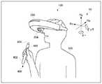
図1は、実施の形態に係る映像提示システム100の全体構成の概観を模式的に示す図である。実施の形態に係る映像提示システム100は、ヘッドマウントディスプレイ200、胴部固定装置300、および位置指定装置400を含む。(Overall configuration of video presentation system 100)
FIG. 1 is a diagram schematically showing an overview of the overall configuration of a
ヘッドマウントディスプレイ200は、その筐体が観察者であるユーザの頭部に装着自在に構成されており、筐体内部に格納された提示部を用いてユーザに3次元映像を提示する。ヘッドマウントディスプレイ200は、例えば電源のオン/オフ等のインタフェースとなる第1ボタン202と、ヘッドマウントディスプレイ200の筐体に備えられ、筐体外部の光を撮像する筐体撮像部204と、ヘッドマウントディスプレイ200の筐体に備えられ、筐体外部に光を照射する筐体発光素子210とをさらに備える。また筐体撮像部204は、第1撮像素子206と第2撮像素子208とをさらに含む。 The head mounted
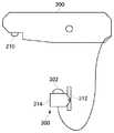
胴部固定装置300は、ヘッドマウントディスプレイ200を装着するユーザの胴部、一例としてはユーザの胸部付近に設置されるように構成されており、ヘッドマウントディスプレイ200の筐体発光素子210が照射する光を撮像する。このため、胴部固定装置300は、胴部撮像素子302と、ユーザ500に装着自在に構成された素子支持部314を備える。図1に示すように、胴部固定装置300とヘッドマウントディスプレイ200とは有線接続されており、ヘッドマウントディスプレイ200は、胴部撮像素子302が撮像した映像を取得することができる。ヘッドマウントディスプレイ200は、取得した画像を解析することにより、胴部固定装置300に対する筐体発光素子210の相対位置を特定することが可能となる。なお、胴部固定装置300とヘッドマウントディスプレイ200とを、例えば赤外線通信等の技術を用いて無線接続してもよい。また、素子支持部314は、胴部撮像素子302の傾きを調整する調整部312も含む。 The
位置指定装置400は、ユーザが把持するための把持部402と、把持部402に取り付けられた発光素子である位置指定発光素子404と、位置指定発光素子404の発光の仕方を制御するための第2ボタン406とを備える。ユーザが第2ボタンをオンする場合とオフする場合とでは、位置指定発光素子404の発光の仕方が変化する。ヘッドマウントディスプレイ200の筐体撮像部204は、位置指定発光素子404が照射する光を撮像して画像化する。ヘッドマウントディスプレイ200はその画像を解析することにより、位置指定発光素子404の位置および第2ボタンの押下の有無を特定することが可能となる。なお、位置指定装置400は必ずしも把持部402を備える必要はなく、位置指定発光素子404がユーザの手の動きと連動して移動する構成であればよい。例えば、位置指定装置400は、指輪や腕輪に位置指定発光素子404を備える構成であってもよい。 The
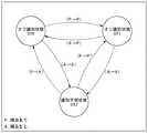
図2は、実施の形態に係る映像提示システム100の利用シーンを模式的に示す図である。図2に示すように、ヘッドマウントディスプレイ200は使用時にユーザ500の頭部に装着され、ユーザ500の頭部の動きに連動して動く。胴部固定装置300は、ネックレスのようにユーザの首にかけられた紐状部材によってつり下げられ、例えばユーザの胸部中央から腹部上方の付近に設置される。なお図示はしないが、胴部固定装置300は、例えばベルト等の固定部材を用いてユーザの胴部に固定されてもよい。位置指定装置400は、使用時にユーザ500によって把持される。このため、ユーザ500が位置指定装置400を掴む手を動かすと、位置指定発光素子404もユーザの手の動きと連動して移動する。 FIG. 2 is a diagram schematically illustrating a usage scene of the
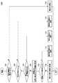
図3は、実施の形態に係る映像提示システム100の内部構成を模式的に示す図である。上述したように、実施の形態に係る映像提示システム100は、ヘッドマウントディスプレイ200、胴部固定装置300、および位置指定装置400を含む。 FIG. 3 is a diagram schematically illustrating an internal configuration of the
ヘッドマウントディスプレイ200は、上述した第1ボタン202、筐体撮像部204の他に、記憶部212、通信部214、記録媒体インタフェース216、提示部218、音声出力部220、CPU(Central Processing Unit)222、加速度センサ224、第1LED(Light Emitting Diode)226、電源228、内部パス230、およびI/O(Input/Output)制御部232を含む。 The head mounted
第1撮像素子206は、例えば赤外光等の不可視光領域の光を撮像するように構成されている。具体的には、第1撮像素子206は撮像の対象とする不可視光領域以外の光を減衰させる光学フィルタを透過した光を撮像する。これに対し、第2撮像素子208は可視光領域以外の光を減衰させる光学フィルタを備え、可視光領域の光を撮像する。第1撮像素子206と第2撮像素子208とはともに、例えばCCD(Charge Coupled Device)イメージセンサやCMOS(Complementary Metal Oxide Semiconductor)イメージセンサ等の既知の固体撮像素子で実現できる。 The
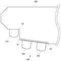
また第1撮像素子206と第2撮像素子208とはともに魚眼レンズを備えており、ヘッドマウントディスプレイ200がユーザ500の頭部に装着されたときに、ヘッドマウントディスプレイ200の筐体に対して鉛直下方向かつユーザ500の視線方向前方の光を撮像する。図1において符号S1と符号S2とを結ぶ線分で示すように、ヘッドマウントディスプレイ200の筐体の下面には、ユーザ500がヘッドマウントディスプレイ200を装着した状態で、ユーザ500側から視線方向かつ鉛直上方向に向かって傾斜するスロープ領域が存在する。第1撮像素子206と第2撮像素子208とともに、ヘッドマウントディスプレイ200の筐体下面に存在するスロープ領域に備えられている。これにより、第1撮像素子206と第2撮像素子208とは、ヘッドマウントディスプレイ200がユーザ500の頭部に装着されたときに、ヘッドマウントディスプレイ200の筐体に対して鉛直下方向かつユーザ500の視線方向前方の光を撮像することができる。 Further, both the
記憶部212は、ヘッドマウントディスプレイ200の動作を統括的に制御するためのオペレーションプログラムを含むファームウェアを格納する。記憶部212はまた、筐体撮像部204が撮像した画像や胴部固定装置300から取得した画像を格納したり、CPU22が実行したりする処理等の作業領域となる。記憶部212は、例えば既知の揮発性および不揮発性のメモリを用いて実現できる。 The
通信部214は、ヘッドマウントディスプレイ200が映像提示システム100の外部の機器と通信するためのインタフェースである。通信部214は、例えばWiFi(登録商標)やBluetooth(登録商標)等の既知の無線通信技術を用いて実現できる。 The communication unit 214 is an interface for the head mounted
記録媒体インタフェース216は、映画やゲーム等のコンテンツを格納するDVD(Digital Versatile Disc)やBluray(登録商標)ディスク、あるいはフラッシュメモリ等の記録媒体を読み出すインタフェースである。記録媒体インタフェース216が読み出したコンテンツはCPU222で処理され、提示部218や音声出力部220を介してユーザに提供される。記録媒体インタフェース216は、例えば光学ドライブ等の既知の技術を用いて実現できる。 The
提示部218は、ユーザ500に映像を提示するためのデバイスである。図示はしないが、提示部218は左目用の提示部と右目用の提示部とを備え、ユーザ500の左目および右目にそれぞれ左目用視差画像および右目用視差画像を独立に提示することができる。これにより、ユーザ500に奥行きを持った3次元映像を提示することが可能となる。提示部218は、LCD(Liquid Crystal Display)やOELD(Organic Electro-Luminescence Display)等の既知の表示技術を用いて実現できる。 The
音声出力部220は、ユーザ500に音声を提示するためのデバイスである。図示はしないが、音声出力部220は左耳用イヤホンと右耳用イヤホンに接続されており、ユーザにステレオ音声を提供することができる。 The
CPU222は、内部パス230を介してヘッドマウントディスプレイ200内の各部から取得した情報を処理し、コンテンツの提供や、後述する頭部追跡処理および手部追跡処理等の処理を実行する。 The
加速度センサ224は、ヘッドマウントディスプレイ200の加速度を検出する。より具体的には、加速度センサ224は、ヘッドマウントディスプレイ200の傾きを検出するために、重力の向きを検出する。加速度センサ224は、例えば既知の低g加速度センサを用いて実現できる。また第1LED226は、ヘッドマウントディスプレイ200の外部に光を照射するLED光源であり、例えば赤外光のような不可視領域の光を照射する。上述した筐体発光素子210は、第1LED226によって実現される。 The
I/O制御部232は、第1ボタン202、筐体撮像部204、および加速度センサ224からの入力や、第1LED226による光の照射を制御する。I/O制御部232は、胴部固定装置300内のI/O制御部304との間での情報の送受信も制御する。電源228は図示しないバッテリを含み、ヘッドマウントディスプレイ200の各部に駆動のための電力を供給する。 The I /
胴部固定装置300は、I/O制御部304と第3撮像素子306とを含む。第3撮像素子306は、上述した胴部撮像素子302対応し、CCDやCMOS等の既知の撮像素子で実現できる。また第3撮像素子306は透視投影レンズを備えている。詳細は後述するが、第3撮像素子306は、ヘッドマウントディスプレイ200内の第1LED226が照射する光の波長付近の光を透過し、その他の波長の光を減衰させる光学フィルタを備えている。これにより、第1LED226が照射する光を選択的に撮像することができる。胴部固定装置300の各部が駆動するための電力は、電源228から図示しない有線で供給する。 The
I/O制御部304は、第3撮像素子306が撮像した画像をヘッドマウントディスプレイ200内のI/O制御部232に出力する。またI/O制御部304は、ヘッドマウントディスプレイ200内のI/O制御部232から第3撮像素子306の撮像の開始および停止の指示を受信し、第3撮像素子306の撮像動作を制御する。 The I /
位置指定装置400は、第2ボタン406、I/O制御部408、第2LED410、および電源412を含む。 The
第2LED410は、上述した位置指定発光素子404に対応し、I/O制御部408の制御の下、例えば赤外光のような不可視領域の光を照射する。I/O制御部408は、第2ボタン406のオン/オフに応じて第2LED410の発光の仕方を制御する。具体的には、I/O制御部408は、第2ボタン406がオンのときは、第2LED410を常時点灯させる。また第2ボタン406がオフのとき、I/O制御部408は所定の点滅周波数で第2LED410を点滅させる。ここで点滅周波数がF[Hz]であると仮定すると、第2ボタン406がオフの場合I/O制御部408は、1/(2×F)秒間第2LED410を点灯させ、続く1/(2×F)秒間第2LED410を消灯させる制御を繰り返す。電源412は図示しないバッテリを含み、位置指定装置400の各部に駆動のための電力を供給する。 The
図4は、実施の形態に係るヘッドマウントディスプレイ200の機能構成を模式的に示す図である。実施の形態に係るヘッドマウントディスプレイ200は、魚眼レンズ234、筐体撮像部204、提示部218、画像取得部250、追跡部260、コンテンツ再生部270、および合成部280を含む。画像取得部250は、第1画像取得部252と第2画像取得部254とをさらに含む。また追跡部260は、頭部追跡部600、手部追跡部700、および出力部262をさらに含む。 FIG. 4 is a diagram schematically illustrating a functional configuration of the head mounted
魚眼レンズ234は、180度程度の画角を持つレンズであり、例えば等距離射影方式で撮像するために用いられる。上述した第1撮像素子206と第2撮像素子208とはともに、魚眼レンズ234を介して撮像するが、図4においては第1撮像素子206と第2撮像素子208とを筐体撮像部204と総称している。以下本明細書において、第1撮像素子206と第2撮像素子208とを区別する必要がある場合を除いて、第1撮像素子206と第2撮像素子208とを筐体撮像部204と総称する。第1撮像素子206と第2撮像素子208とは、それぞれ別の魚眼レンズを介して撮像してもよい。 The
上述したように、位置指定装置400は、使用時にユーザ500の手で把持される。このため、位置指定発光素子404は、ヘッドマウントディスプレイ200の筐体に対して鉛直下方向かつユーザ500の視線方向前方に存在することになる。筐体撮像部204は、ヘッドマウントディスプレイ200がユーザ500の頭部に装着されたときに、ヘッドマウントディスプレイ200の筐体に対して鉛直下方向かつユーザ500の視線方向前方の光を撮像することができる。このため、筐体撮像部204はユーザ500の手の動きと連動して移動する位置指定発光素子404を容易に画角に捉えることができる。 As described above, the
画像取得部250内の第2画像取得部254は、筐体撮像部204が撮像した画像を取得する。追跡部260内の手部追跡部700は、筐体撮像部204が撮像した画像を第2画像取得部254から取得する。手部追跡部700は取得した画像を解析することにより、位置指定発光素子404に由来する輝点の位置変化を追跡する。位置指定発光素子404はユーザ500の手の動きと連動して移動するので、結果として手部追跡部700はユーザ500の手の動きを検出することができる。手部追跡部700は、図3における記憶部212に格納された手部追跡処理を実現するためのプログラムをCPU222が実行することによって実現できる。手部追跡部700における手部追跡処理の詳細は後述する。 A second
画像取得部250内の第1画像取得部252は、胴部固定装置300の胴部撮像素子302が撮像した画像を取得する。頭部追跡部600は、第1画像取得部252が取得した画像を取得する。 The first
上述したように、胴部撮像素子302はヘッドマウントディスプレイ200の筐体発光素子210が照射する光を含む被写体を撮像する。したがって、第1画像取得部252が取得した画像には、筐体発光素子210を由来とする輝点が撮像されている。そこで頭部追跡部600は、取得した画像を解析することにより、位置指定発光素子404の位置変化を追跡する。これにより、頭部追跡部600は、胴部撮像素子302に対する筐体発光素子210の相対的な動きを検出することができる。結果として、頭部追跡部600は、ユーザ500の胴部に対するユーザ500の頭の向き、すなわち視線方向を検出することができる。手部追跡部700は、図3における記憶部212に格納された頭部追跡処理を実現するためのプログラムをCPU222が実行することによって実現できる。なお、頭部追跡部600における頭部追跡処理の詳細は後述する。 As described above, the
追跡部260内の出力部262は、頭部追跡部600および手部追跡部700の処理結果を出力する。コンテンツ再生部270は、記録媒体インタフェース216が読み出したコンテンツを再生する。コンテンツ再生部270は、出力部262から取得した追跡部260の出力結果に応じて、ユーザ500に提示する映像を変更する。例えば、ユーザ500の視線が胴部に対して左方向を向いている場合、コンテンツ再生部270は、左方向に対応する3次元映像を提示部218に表示させる。コンテンツ再生部270は、記憶部212およびCPU222のリソースを用いて実現できる。 The
合成部280は、コンテンツ再生部270が生成した映像と、筐体撮像部204が撮像した映像とを合成する。具体的には、合成部280は、出力部262からユーザ500の視線方向を取得する。取得したユーザの視線方向が鉛直下方向、すなわちユーザ500の手元や足下の方向である場合、合成部280は、筐体撮像部204が撮像した可視光画像をコンテンツ再生部270が生成した映像に合成する。合成部280による映像の合成は、アルファブレンディング等の既知の画像処理技術を実現するためのプログラムをCPU222が実行することで実現できる。手元方向を取得する別の手段として、後述する手部追跡によって取得できるヘッドマウントディスプレイ200の座標系10に対する、位置指定発光素子404の方向を利用することもできる。 The synthesizing
実施の形態に係るヘッドマウントディスプレイ200は、ユーザ500の頭部に装着されたときにユーザ500の両眼球の前方に位置し、周囲の視界を遮断するように構成されている。ユーザ500は提示部218が提示する仮想的な3次元映像を観察することになるので、ユーザ500に対してより高い没入感や臨場感を提供することができる。一方、合成部280がユーザ500の手元や足下付近の現実の映像を合成することにより、ユーザ500がヘッドマウントディスプレイ200を装着した状態で行う手元の操作や歩行等が容易となり、ユーザビリティを向上させることができる。なお、合成部280が筐体撮像部204が撮像した画像を合成するか否かは、例えば第1ボタン202を押下することで切り替え自在としてもよい。 The head mounted
図5は、実施の形態に係る映像提示システム100による追跡処理の流れを示すフローチャートである。本フローチャートにおける処理は、例えばヘッドマウントディスプレイ200の電源が投入されたときに開始する。 FIG. 5 is a flowchart showing a flow of tracking processing by the
筐体撮像部204は、位置指定装置400の位置指定発光素子404が照射する光を撮像して画像化する(S2)。手部追跡部700は、筐体撮像部204撮像した画像を解析して、ユーザ500の手の動きを検出する(S4)。 The
筐体発光素子210は、I/O制御部232の制御の下、ヘッドマウントディスプレイ200に対して鉛直下方向に光を照射する(S6)。胴部固定装置300の胴部撮像素子302は、筐体発光素子210が鉛直下方向に照射した光を撮像して画像を取得する(S8)。頭部追跡部600は、第1画像取得部252が取得した胴部撮像素子302による画像を解析して、胴部撮像素子302に対するヘッドマウントディスプレイ200の相対的な動きを検出する(S10)。 The casing
頭部追跡部600が胴部撮像素子302に対するヘッドマウントディスプレイ200の相対的な動きを検出すると、本フローチャートにおける処理は終了する。なお、説明の便宜上、手部追跡部700による手の動き検出の後に頭部追跡部600による頭部の動き検出を実行する場合について説明したが、頭部の動き検出の後に手の動き検出を実行してもよいし、両者を並列に実行してもよい。 When the
(手部追跡)
以上、映像提示システム100の全体構成および追跡処理の概要について説明した。続いて、実施の形態に係る手部追跡について説明する。(Hand tracking)
The overall configuration of the
図6は、実施の形態に係る映像提示システム100のうち、手部追跡に用いる構成を模式的に示す図である。図6に示すように、実施の形態に係る手部追跡においては、ヘッドマウントディスプレイ200と位置指定装置400とを用いる。 FIG. 6 is a diagram schematically illustrating a configuration used for hand tracking in the
図7は、実施の形態に係る映像提示システム100の手部追跡の利用シーンを模式的に示す図である。実施の形態に係る手部追跡は、ヘッドマウントディスプレイ200の座標系10(Hx,Hy,Hz)に対する、位置指定発光素子404の方向をピッチ(pitch)およびヨー(yaw)の組として取得する。図7に示す座標系10は、筐体撮像部204の位置を原点とし、鉛直方向上向きにHy軸を設定し、ユーザ500の頭部の左手側から右手側に向かう向きにHx軸を設定し、ユーザ500の頭部の正面から背面に向かう向きにHz軸を設定した座標系である。なお図7においては、胴部固定装置300を省略して図示している。 FIG. 7 is a diagram schematically showing a use scene of hand tracking of the
図8は、実施の形態に係る筐体撮像部204が撮像した画像256の一例を模式的に示す図である。図8において、点Oは筐体撮像部204が撮像した画像256の中心点であり、点Pは位置指定発光素子404に由来する輝点である。上述したとおり、筐体撮像部204は魚眼レンズ234を介して等距離射影方式で撮像する。したがって、位置指定発光素子404が筐体撮像部204の光軸上に存在する場合、輝点Pは画像256の中心点Oの位置に存在する。 FIG. 8 is a diagram schematically illustrating an example of an
位置指定発光素子404から筐体撮像部204の光軸までの距離、すなわち、位置指定発光素子404から筐体撮像部204の光軸上に下ろした垂線の長さが長いほど、画像256における輝点Pと中心点Oとの距離は長くなる。また、位置指定発光素子404から筐体撮像部204の光軸までの距離を一定に保ったまま位置指定発光素子404を動かすと、画像256における輝点Pは、中心点Oを中心とする円弧上を移動する。 The longer the distance from the position-designated
このことから、線分OPを動径ベクトルとしたきのベクトルの長さLを計測することにより、座標系10に対する位置指定発光素子404のピッチを取得することができる。また、動径ベクトルの偏角θを計測することにより、座標系10に対する位置指定発光素子404のヨーを取得することができる。 From this, the pitch of the position-designated
図9は、実施の形態に係る手部追跡部700の機能構成を模式的に示す図である。手部追跡部700は、輝点検出部710、ベクトル取得部720、ピッチ取得部730、ヨー取得部740、およびジェスチャー認識部750を含む。 FIG. 9 is a diagram schematically illustrating a functional configuration of the
輝点検出部710は、第2画像取得部254から筐体撮像部204が撮像した画像を取得する。輝点検出部710は取得した画像中から位置指定発光素子404に由来する輝点Pを検出する。上述したとおり、位置指定発光素子404は、第2ボタン406のオン/オフに応じて常時点灯かまたは点滅かが変化する。そこで輝点検出部710は、検出した輝点が常時点灯であるか点滅しているかも検出し、第2ボタン406の押下の有無も検出する。輝点検出部710は例えばパターンマッチング等、既知の画像処理技術を用いて実現できる。なお、輝点検出部710による第2ボタン406の押下有無の検出処理の詳細は後述する。 The bright
ベクトル取得部720は、輝点検出部710が検出した輝点Pを終点とし、筐体撮像部204が撮像した画像256の中心点Oを始点とする動径ベクトルを取得する。ピッチ取得部730は、ベクトル取得部720が取得した動径ベクトルの長さLから、筐体撮像部204の位置を原点とする座標系10に対する位置指定発光素子404のピッチを取得する。ヨー取得部740は、ベクトル取得部720が取得した動径ベクトルの偏角θから、筐体撮像部204の位置を原点とする座標系10に対する位置指定発光素子404のヨーを取得する。 The
ジェスチャー認識部750は、筐体撮像部204内の第2撮像素子208が撮像した画像を取得する。上述したとおり、第2撮像素子208は可視光領域の光を撮像する。第2撮像素子208は、例えばユーザ500が位置指定装置400を所持していない場合等に、ユーザ500の手部を撮像する。ジェスチャー認識部750は、第2撮像素子208が撮像したユーザ500の手の形を認識して、その情報を出力部262に出力する。 The
一例として、例えば親指と人差し指とで輪を作るジェスチャーを第2ボタン406のオンに対応させ、握り拳を第2ボタン406のオフに対応させるとする。このとき、ジェスチャー認識部750が第2撮像素子208が撮像した画像中に親指と人差し指とで輪を作るジェスチャーを検出した場合、輝点検出部710が第2ボタン406のオンを検出した場合と同様の信号を出力する。同様に、ジェスチャー認識部750が第2撮像素子208が撮像した画像中に握り拳を検出した場合、輝点検出部710が第2ボタン406のオンを検出した場合と同様の信号を出力する。 As an example, it is assumed that, for example, a gesture of making a ring with the thumb and forefinger corresponds to the
これにより、ユーザ500が位置指定装置400を所持していない場合であっても、ユーザ500による第2ボタン406の押下と同様の情報を取得することができる。ジェスチャー認識部750はさらに、上記以外の他のジェスチャーを認識するようにしてもよい。これにより、第2ボタン406の押下よりも多くの情報をユーザ500から取得することができる。ジェスチャー認識部750は、例えば機械学習を用いたパターン認識を利用する等、既知の画像認識技術を用いて実現できる。またジェスチャー認識部750と位置指定装置400の使用とを併用してもよい。ジェスチャー認識部750は、筐体撮像部204内の第1撮像素子206が撮像した画像を取得することにより、手部追跡の軌跡をジェスチャーとして認識することもできる。 Thereby, even when the
図10は、実施の形態に係る手部追跡部処理の流れを示すフローチャートであり、図5におけるステップS5を詳細に示す図である。 FIG. 10 is a flowchart showing the flow of the hand tracking unit process according to the embodiment, and shows in detail step S5 in FIG.
第2画像取得部254は、筐体撮像部204が撮像した位置指定発光素子404が照射する赤外光を筐体撮像部204が撮像した画像を取得する(S402)。輝点検出部710は、第2画像取得部254から取得した画像における赤外光に由来する輝点を検出する(S404)。 The second
ベクトル取得部720は、輝点検出部710が検出した輝点を終点とし、筐体撮像部204が撮像した画像の中心を始点とするベクトルを取得する(S406)。ピッチ取得部730は、ベクトル取得部720が取得したベクトルの長さ取得する(S408)。ヨー取得部740は、ベクトル取得部720が取得したベクトルの偏角を取得する(S410)。 The
(頭部追跡)
以上、実施の形態に係る手部追跡について説明した。続いて、実施の形態に係る頭部追跡について説明する。(Head tracking)
The hand tracking according to the embodiment has been described above. Next, head tracking according to the embodiment will be described.
図11は、実施の形態に係る映像提示システム100のうち、頭部追跡に用いる構成を模式的に示す図である。図11に示すように、実施の形態に係る手部追跡においては、ヘッドマウントディスプレイ200と胴部固定装置300とを用いる。 FIG. 11 is a diagram schematically illustrating a configuration used for head tracking in the
図12は、実施の形態に係る映像提示システム100の頭部追跡の利用シーンを模式的に示す図である。実施の形態に係る頭部追跡は、胴部固定装置300の座標系12(Bx,By,Bz)に対する、ヘッドマウントディスプレイ200の座標系10(Hx,Hy,Hz)の相対的な姿勢角(Hpitch,Hyaw,Hroll)の変化を検出する。ここでHpitchは座標系12に対する座標系10のピッチ、Hyawは座標系12に対する座標系10のヨー、Hrollは座標系12に対する座標系10のロール(roll)を表す。胴部固定装置300の座標系12に対するヘッドマウントディスプレイ200の座標系10の変化は、ユーザ500の胴部に対する頭部の位置変化に対応する。 FIG. 12 is a diagram schematically showing a use scene for head tracking of the
図12に示す座標系12は、胴部撮像素子302の位置を原点とし、鉛直方向上向きにBy軸を設定し、ユーザ500左手側から右手側に向かう向きにBx軸を設定し、ユーザ500の正面から背面に向かう向きにBz軸を設定した座標系である。なお図12においては、位置指定装置400を省略して図示している。 The coordinate
胴部固定装置300の座標系12において、By軸は重力方向に対して平行であり、Bx軸とBz軸は重力方向に対して垂直である。同様に、ユーザ500が正面を向いている場合、ヘッドマウントディスプレイ200の座標系10におけるHy軸は重力方向に対して平行であり、Hx軸とHz軸は重力方向に対して垂直である。 In the coordinate
胴部固定装置300の座標系12が示すように、ユーザ500が首を上下に動かす場合、すなわち床を見たり天井を見上げたりする場合、座標系12に対するヘッドマウントディスプレイ200の座標系10のピッチが変化する。また、ユーザ500が首を左右に傾ける場合、すなわち首をかしげる動作をする場合、座標系12に対する座標系10のロールが変化する。座標系12に対する座標系10のピッチまたはロールが変化すると、座標系10のHx軸とHz軸は、重力方向に対して垂直からずれる。この「ずれ」を図3における加速度センサ224を用いて検出することにより、座標系12に対する座標系10のピッチまたはロールを検出することができる。 As indicated by the coordinate
これに対し、重力方向の変化から座標系12に対する座標系10のヨーの変化を検出することは難しい。例えば、ユーザ500が首を垂直に保ったまま、左右を向くと座標系12に対する座標系10のヨーが変化する。しかしながら、座標系10におけるHy軸は重力方向と平行を保ったまま変化しない。そこで実施の形態に係る映像提示システム100は筐体発光素子210が照射する光を胴部撮像素子302で撮像し、その画像を解析することで座標系12に対する座標系10のヨーの変化を検出する。以下、胴部撮像素子302が撮像した画像から座標系12に対する座標系10のヨーの変化を検出する原理について説明する。 On the other hand, it is difficult to detect the change in the yaw of the coordinate
図13は、実施の形態に係る胴部撮像素子302が撮像した画像308の一例を模式的に示す図である。具体的には、ユーザ500がヘッドマウントディスプレイ200を装着した状態で正面を向いて首を左右に回旋した場合における、筐体発光素子210に由来する輝点の軌跡を示す。一般に人間が首を左右に回旋可能な角度は、左右それぞれ60度前後といわれている。したがって、ユーザ500がヘッドマウントディスプレイ200を装着した状態で正面を向いて首を左右に回旋すると、筐体発光素子210に由来する輝点の軌跡は中心角が120度前後の扇形の円弧となる。 FIG. 13 is a diagram schematically illustrating an example of an
図13において、点Pはユーザ500が正面を向いているときの、筐体発光素子210に由来する輝点を示す。点Qはユーザ500が首を右に最大限旋回させたときの、筐体発光素子210に由来する輝点を示す。また点Rはユーザ500が首を左に最大限旋回させたときの、筐体発光素子210に由来する輝点を示す。筐体発光素子210に由来する輝点の軌跡が円弧を描くことを仮定すると、点P、点Q、および点Rの3点は同一円周上に存在することになる。一般に、異なる3点を通る円は一意に定まるので、点P、点Q、および点Rを検出することにより、上記の円弧を特定することができる。 In FIG. 13, a point P indicates a bright spot derived from the casing
ここで、ユーザ500が首を前屈または後屈した状態で首を左右に回旋する場合、画像308における筐体発光素子210に由来する輝点の軌跡が描く円弧の半径は、ユーザ500が正面を向いている場合と比較して短くなる。ユーザ500が首を前屈または後屈すると、筐体発光素子210は回転軸となるユーザ500の首に近づくからである。 Here, when the
図13における円弧CDは、ユーザ500が首を前屈または後屈した状態で首を左右に回旋した場合の軌跡を例示している。このことから、画像308において筐体発光素子210に由来する輝点が存在すると考えられる「筐体発光素子210の存在領域」が存在することを本願の発明者は見いだした。より具体的には、図13における点P、点Q、および点Rを通る中心角が180度の円弧で囲まれた領域である。筐体発光素子210の存在領域は図13において線分ABおよび円弧ABで囲まれた領域である。なお、図13における点Oは、円弧の中心点である。 An arc CD in FIG. 13 illustrates a locus when the
上述したように、胴部固定装置300は、胴部撮像素子302と、胴部撮像素子302とを支持する素子支持部314を備える。また、素子支持部314は、胴部撮像素子302の傾きを調整する調整部312も含む。ユーザ500は映像提示システム100を使用する際には、胴部撮像素子302が撮像する画像308内に「筐体発光素子210の存在領域」が含まれるように調整部312を用いて胴部撮像素子302の傾きを調整するキャリブレーションを実行する。これにより、画像308内に筐体発光素子210に由来する輝点が存在する可能性を高めることができる。 As described above, the
図14は、実施の形態に係る頭部追跡部600の機能構成を模式的に示す図である。実施の形態に係る頭部追跡部600は、領域設定部610と輝点解析部620とを含む。領域設定部610は、第1画像取得部252から胴部撮像素子302が撮像した画像308を取得する。領域設定部610は、既に「筐体発光素子210の存在領域」が定まっている場合、画像308に筐体発光素子210の存在領域を設定する。 FIG. 14 is a diagram schematically illustrating a functional configuration of the
輝点解析部620は、画像308を解析して胴部撮像素子302に対する筐体発光素子210のヨー(yaw)を検出する。以下、輝点解析部620の詳細を説明する。 The bright
輝点解析部620は、輝点選別部630、軌跡検出部640、フィッティング部650、ベクトル取得部660、およびヨー取得部670を含む。輝点選別部630は、画像308に複数の輝点が存在する場合、その複数の輝点の中から筐体発光素子210に由来する輝点を選別する。 The bright
画像308に複数の輝点が存在する場合とは、筐体発光素子210に由来する輝点の他に、例えば位置指定発光素子404に由来する輝点が考えられる。輝点選別部630による選別処理の詳細は後述する。 The case where there are a plurality of bright spots in the
軌跡検出部640は、胴部撮像素子302が撮像した画像308中において輝点選別部630が選別した輝点の軌跡を検出する。フィッティング部650は、軌跡検出部640が検出した軌跡にフィットする円弧を取得する。フィッティング部650は、胴部撮像素子302の傾きを調整するキャリブレーション実行時には、取得した円弧を筐体発光素子210の存在領域として領域設定部610に出力する。 The
ベクトル取得部660は、フィッティング部650が取得した円弧の中心点を始点とし、輝点選別部630が選別した輝点を終点とする動径ベクトルを取得する。ヨー取得部670は、手部追跡部700中のヨー取得部740と同様に、ベクトル取得部660が取得した動径ベクトルの偏角を取得して、胴部撮像素子302に対する筐体発光素子210のヨーを検出する。 The
図15は、実施の形態に係る頭部追跡部処理の流れを示すフローチャートであり、図5におけるステップS10を詳細に示す図である。 FIG. 15 is a flowchart showing the flow of the head tracking unit process according to the embodiment, and shows in detail step S10 in FIG.
領域設定部610は、胴部撮像素子302が撮像した画像308中に筐体発光素子210の存在領域を設定する(S102)。輝点選別部630は、領域設定部610が設定した領域内に複数の輝点が存在する場合、筐体発光素子210に起因する輝点を特定する(S104)。軌跡検出部640は、胴部撮像素子302が撮像した画像308中において輝点選別部630が選別した輝点の軌跡を検出する(S106)。 The
フィッティング部650は、軌跡検出部640が検出した軌跡にフィットする円弧を取得する(S108)。ベクトル取得部660は、フィッティング部650が取得した円弧の中心点を始点とし、輝点選別部630が選別した輝点を終点とする動径ベクトルを取得する(S110)。ヨー取得部670は、ベクトル取得部660が取得した動径ベクトルの偏角を取得する(S112)。 The
(手部追跡と頭部追跡との併用)
以上、実施の形態に係る頭部追跡について説明した。続いて、実施の形態に係る手部追跡と頭部追跡とを併用する場合について説明する。(Combination of hand tracking and head tracking)
The head tracking according to the embodiment has been described above. Next, a case where hand tracking and head tracking according to the embodiment are used together will be described.
(筐体発光素子210と筐体撮像部204との位置関係)
図16は、実施の形態に係るヘッドマウントディスプレイ200の一部を拡大した図であり、筐体発光素子210と筐体撮像部204との位置関係を示す図である。(Positional relationship between the casing
FIG. 16 is an enlarged view of a part of the head mounted
上述したように、筐体撮像部204中の第1撮像素子206および第2撮像素子208は、ヘッドマウントディスプレイ200の筐体のスロープ領域に備えられる。図16において、スロープ領域は符号S1と符号S2とを結ぶ線分および斜線で示す領域である。ここで筐体撮像部204は、位置指定発光素子404を撮像することを目的としている。したがって、筐体撮像部204は、頭部追跡に利用する筐体発光素子210が照射する光を撮像しないようにすることが好ましい。 As described above, the
そこでヘッドマウントディスプレイ200の筐体は、筐体撮像部204と筐体発光素子210との間を遮蔽するように構成されている。具体的には、図16の符号S1およびS3で示すように、筐体の少なくとも一部分が筐体撮像部204と筐体発光素子210との間に存在するように構成されている。これにより、筐体発光素子210が照射する光が筐体撮像部204の画角に入ったり、少なくとも領域設定部610が設定する筐体発光素子210の存在領域内に入ったりすることを軽減することができる。 Therefore, the housing of the head mounted
また上述したように、筐体発光素子210は、胴部固定装置300の座標系12に対する、ヘッドマウントディスプレイ200の座標系10のヨーの変化を検出することを目的としている。ここでフィッティング部650は、ヨーの変化を検出する際に円フィッティングを実行するが、一般に、フィッティングの対象とする円の半径が大きい方がフィッティングの精度が高くなる。そのため、筐体発光素子210は、ユーザ500がヘッドマウントディスプレイ200を装着したときに、ユーザ500の頭部からなるべく離れた場所に位置する方が好ましい。 Further, as described above, the housing
そこで、筐体発光素子210は、ヘッドマウントディスプレイ200がユーザ500の頭部に装着されたときに、筐体撮像部204の設置位置と比較して、ユーザの500視線方向前方に設置される。また上述したように筐体撮像部204と筐体発光素子210との間に存在するように構成されているため、筐体発光素子210は筐体撮像部204の設置位置と比較して鉛直方向上方に設置される。これにより、胴部撮像素子302が撮像する画像308中において、筐体発光素子210に由来する輝点の軌跡が描く円弧の半径を大きくすることができ、フィッティング部650による円フィッティングの精度を高めることが可能となる。 Therefore, when the head mounted
(輝点選別)
続いて、輝点選別部630による輝点選別処理について説明する。(Bright spot selection)
Next, the bright spot selection process by the bright spot selection unit 630 will be described.
上述したとおり、輝点解析部620は領域設定部610が設定した筐体発光素子210の存在領域内に存在する輝点の動きを解析して筐体発光素子210の動きを検出するが、筐体発光素子210の存在領域内に輝点が複数存在する場合には、まずその中から筐体発光素子210に由来する輝点を選別する。例えば、手部追跡と頭部追跡とを併用する場合には、筐体発光素子210の存在領域内に位置指定発光素子404に由来する輝点が映り込むことも起こりうる。 As described above, the bright
そこで輝点選別部630は、胴部撮像素子302が撮像した画像308中に設定された筐体発光素子210の存在領域において検出した複数の輝点の大きさをもとに、筐体発光素子210に由来する輝点を選別する。 Therefore, the bright spot selecting unit 630 uses the housing light emitting element based on the size of the plurality of bright spots detected in the existence region of the housing
位置指定発光素子404が照射する光が胴部撮像素子302の画角に入るのは、ユーザ500がヘッドマウントディスプレイ200と胴部撮像素子302との間で位置指定装置400を移動させる場合であると考えられる。この場合、胴部撮像素子302から筐体発光素子210までの距離は、胴部撮像素子302から位置指定発光素子404までの距離よりも長くなる。ここで、実施の形態に係る筐体発光素子210の大きさと位置指定発光素子404の大きさとは同じである。このため、筐体発光素子210の存在領域中に筐体発光素子210に由来する輝点と位置指定発光素子404に由来する輝点とが同時に存在する場合、筐体発光素子210に由来する輝点の大きさの方が、位置指定発光素子404に由来する輝点の大きさよりも小さくなる。 The light emitted from the position designation
そこで、輝点選別部630は、筐体発光素子210の存在領域において検出した複数の輝点の大きさを比較して、小さい輝点を筐体発光素子210に由来する輝点として選択する。これにより、筐体発光素子210の存在領域中に存在する輝点から筐体発光素子210に由来する輝点を容易に判別することが可能となる。 Therefore, the bright spot selection unit 630 compares the sizes of a plurality of bright spots detected in the region where the housing
図17は、実施の形態に係る輝点選別部630による輝点選別処理の流れを示すフローチャートであり、図15におけるステップ104を詳細に説明する図である。 FIG. 17 is a flowchart showing a flow of the bright spot selection processing by the bright spot selection unit 630 according to the embodiment, and is a diagram for explaining
輝点選別部630は、領域設定部610が設定した筐体発光素子210の存在領域内に輝点が存在するかどうかを調べ、輝点が存在しない場合(S20のN)輝点は未検出と判断する(S38)。輝点が存在する場合(S20のY)、輝点選別部630は筐体発光素子210の存在領域内に輝点の数が2以上あるか否かを調べる。輝点の数が2以上でない場合、すなわち輝点の数が1の場合(S22のN)、輝点選別部630は検出した輝点を筐体発光素子210に由来する輝点として選択する(S36)。 The bright spot selection unit 630 checks whether there is a bright spot in the region where the housing
輝点の数が2以上の場合(S22のY)、輝点選別部630は検出した輝点の大きさの大小関係を調べる。大小関係がある場合(S24のY)、輝点選別部630は最小の輝点を筐体発光素子210に由来する輝点として選択する(S34)。大小関係がない場合(S24のN)、輝点選別部630は、前回筐体発光素子210に由来する輝点として選択した輝点の位置から、各輝点までの距離を求める。求めた距離に大小関係がある場合(S28のY)、輝点選別部630は前回の輝点の最近傍に位置する輝点を筐体発光素子210に由来する輝点として選択する(S362)。 When the number of bright spots is 2 or more (Y in S22), the bright spot selection unit 630 checks the magnitude relationship of the detected bright spot sizes. When there is a magnitude relationship (Y in S24), the bright spot selection unit 630 selects the minimum bright spot as the bright spot derived from the casing light emitting element 210 (S34). When there is no magnitude relationship (N in S24), the bright spot selecting unit 630 obtains the distance to each bright spot from the position of the bright spot selected as the bright spot derived from the previous case light emitting
求めた距離に大小関係がない場合(S28のN)、輝点選別部630は各輝点の位置の重心の座標を取得し、その座標位置に筐体発光素子210に由来する輝点が存在すると見なす(S30)。 When the obtained distance is not related to the magnitude (N in S28), the bright spot selecting unit 630 acquires the coordinates of the center of gravity of the position of each bright spot, and the bright spot derived from the housing
(位置指定装置400からの信号の検出)
以上、輝点選別部630による輝点選別処理について説明した。続いて、輝点検出部710による、位置指定装置400の第2ボタン406における押下有無の検出処理について説明する。(Detection of signal from position specifying device 400)
The bright spot selection process by the bright spot selection unit 630 has been described above. Next, a detection process of whether or not the
上述したとおり、位置指定発光素子404は、第2ボタン406がオンのときは常時点灯し、第2ボタン406がオフのときは所定の点滅周波数Fで点滅する。輝点選別部630は、筐体撮像部204が撮像する画像256中の位置指定発光素子404に由来する輝点の有無を解析することにより、第2ボタン406の押下有無を検出する。 As described above, the position-designated
より具体的には、筐体撮像部204は、位置指定発光素子404の点滅周波数Fの少なくとも2倍の周波数2Fで撮像して取得した画像256を解析する。筐体撮像部204が、位置指定発光素子404の点滅周波数の少なくとも2倍の周波数で画像256を撮像し、連続する2フレーム分の画像256を解析することにより、輝点検出部710は位置指定発光素子404が常時点灯であるか、周波数F(周期T=1/F)で点滅しているか、あるいは画像256中に画像が存在しないかを識別可能であることが知られている。点滅周波数Fは筐体撮像部204の時間分解能等を考慮して実験により定めればよいが、一例としては120[Hz]である。この場合、第2ボタン406がオフのとき、位置指定発光素子404は1/240秒ごとに点灯と消灯を繰り返す。また筐体撮像部204は少なくとも240[Hz]で位置指定発光素子404を含む被写体を撮像する。 More specifically, the
図18は、実施の形態に係る位置指定装置400が発する信号を検出する処理の流れを示すフローチャートであり、位置指定発光素子404の制御を示す図である。 FIG. 18 is a flowchart showing a flow of processing for detecting a signal generated by the
位置指定装置400内のI/O制御部408は、トグルを初期化する(S40)。ここで「トグル」は、第2ボタン406が押下げられていない場合に第2LEDを点灯するか消灯するかを示すバイナリ値である。実施の形態においては、トグルは1/240秒毎に反転しており、I/O制御部408の図示しない一時記録部に格納される。 The I /
I/O制御部408は、第2ボタン406のオン/オフの状態を確認する(S42)。第2ボタン406が押下られている場合(S44のY)、I/O制御部408は位置指定発光素子404である第2LED410を点灯する(S50)。第2ボタン406が押下られていない場合(S44のN)かつトグルが0でない場合も(S46のN)、I/O制御部408は位置指定発光素子404である第2LED410を点灯する(S50)。 The I /
第2ボタン406が押下られていない場合(S44のN)かつトグルが0の場合(S46のY)、I/O制御部408は位置指定発光素子404である第2LED410を消灯する(S48)。その後、トグルが0の場合(S52のY)、I/O制御部408はトグルを反転して1とする(S56)。トグルが0でない場合(S52のN)、I/O制御部408はトグルを反転して0とする(S56)。トグルを反転した後、ステップS42に戻って上述の処理を繰り返す。 When the
I/O制御部408は、ステップS42からステップS54およびS56までの以上の処理を、例えば1/240秒毎に繰り返す。これにより、I/O制御部408は全体として、第2ボタン406のオフの場合には120[Hz]の周期で第2LED410を点滅し、第2ボタン406のオンの場合には第2LED410を継続的に点灯する制御を実現することができる。 The I /
図19は、実施の形態に係る位置指定装置400が発する信号を検出するときの、輝点検出部710の内部状態を示す状態遷移図であり、輝点検出部710の検出処理を説明する図である。 FIG. 19 is a state transition diagram showing an internal state of the bright
輝点検出部710は、筐体撮像部204が撮像した画像をもとに位置指定装置400が発する信号を検出する間、検出した信号に応じて「押下フラグ」の値を変化させる。ここで「押下フラグ」は、位置指定発光素子404に由来する輝点の有無、および輝点を検出した場合には第2ボタン406のオン/オフ状態を検出するために利用する作業メモリであり、記憶部212に格納されている。 The bright
より具体的には、輝点検出部710は、筐体撮像部204が撮像した画像256をフレーム毎に取得して解析する。輝点検出部710は、位置指定発光素子404に由来する輝点が点滅状態であることを検出した場合、すなわち第2ボタン406がオフ状態あると識別した場合、押下フラグの値を0に設定する。輝点検出部710はまた、位置指定発光素子404に由来する輝点が常時点灯状態であることを検出した場合、すなわち第2ボタン406がオン状態あると識別した場合、押下フラグの値を1に設定する。輝点検出部710はさらに、筐体撮像部204が撮像した画像中に位置指定発光素子404に由来する輝点を検出できない場合、押下フラグの値を2に設定する。 More specifically, the bright
ここで、押下フラグの値は輝点検出部710の内部状態と対応する。すなわち、押下フラグの値が0のとき、輝点検出部710はオフ識別状態(ST0)である。また押下フラグの値が1のとき、輝点検出部710はオン識別状態(ST1)であり、押下フラグの値が2のとき、輝点検出部710は識別不明状態(ST2)である。輝点検出部710は、筐体撮像部204が撮像した連続する2フレーム分の画像256を解析し、その結果に応じて内部状態を変更する。 Here, the value of the pressing flag corresponds to the internal state of the bright
例えば、輝点検出部710の内部状態がオフ識別状態(ST0)のとき、連続する2フレーム分の画像256において、どちらも位置指定発光素子404に由来する輝点を検出したとする。この場合、輝点検出部710は押下フラグの値を0から1に変更して内部状態をオン識別状態ST1に遷移させる。連続する2フレーム分の画像256において、どちらも輝点を検出した場合、輝点は常時点灯していると考えられるからである。 For example, assume that when the internal state of the bright
図19においては、オフ状態識別ST0からオン識別状態ST1に向かう矢印と(P→P)とを用いて示している。ここで記号「P」は、画像256中に輝点が存在することを表し、存在を意味する英語Presentの頭文字である。(P→P)は、ある画像256において輝点を検出し、続く画像256においても輝点を検出した事象を示す。 In FIG. 19, an arrow from the off state identification ST0 to the on identification state ST1 and (P → P) are used. Here, the symbol “P” represents the presence of a bright spot in the
輝点検出部710の内部状態がオフ識別状態(ST1)のとき、連続する2フレーム分の画像256において、輝点を検出できない状態から続く画像256において輝点を検出したとする。この場合、輝点検出部710は押下フラグの値を1から0に変更して内部状態をオン識別状態ST1に遷移させる。図19においては、オン状態識別ST1からオフ識別状態ST0に向かう矢印と事象(A→P)とを用いて示している。ここで記号「A」は、画像256中に輝点が存在しないことを表し、存在しないことを意味する英語Absentの頭文字である。事象(A→P)は、ある画像256において輝点を検出せず、続く画像256においても輝点を検出したことを示す。以下同様にして、事象(A→A)を連続する2フレーム分の画像256において、どちらも輝点を検出しない場合を表し、事象(P→A)は、ある画像256において輝点を検出し、続く画像256においては輝点を検出しないことを示す。 When the internal state of the bright
同様に、輝点検出部710の内部状態がオフ識別状態(ST1)のとき、事象(A→A)が起こると、輝点検出部710は押下フラグの値を1から2に変更し、内部状態を識別不明状態ST2に遷移する。連続する2フレーム分の画像256において、どちらも輝点を検出しない場合は、画像256に輝点が存在せず、輝点を見失ったと考えられるからである。輝点検出部710の内部状態が識別不明状態(ST2)のとき、事象(P→P)が起こると、輝点検出部710は押下フラグの値を2から1に変更し、内部状態をオン識別状態ST2に遷移する。 Similarly, when the internal state of the bright
輝点検出部710の内部状態が識別不明状態(ST2)のとき、事象(P→A)が起こると、輝点検出部710は押下フラグの値を2から0に変更し、内部状態をオフ識別状態ST2に遷移する。また輝点検出部710の内部状態がオフ識別状態(ST0)のとき、事象(A→A)が起こると、輝点検出部710は押下フラグの値を0から2に変更し、内部状態を識別不明状態ST2に遷移する。 When the internal state of the bright
以上より、輝点検出部710は、第2ボタン406に由来する輝点の有無、および輝点を検出した場合にはそのオン/オフ状態を識別することができる。 As described above, the bright
以上述べたように、実施の形態に係る映像提示システム100によれば、ヘッドマウントディスプレイを装着したユーザの動きを検出する技術を提供することができる。 As described above, according to the
以上、本発明を実施の形態をもとに説明した。実施の形態は例示であり、それらの各構成要素や各処理プロセスの組合せにいろいろな変形例が可能なこと、またそうした変形例も本発明の範囲にあることは当業者に理解されるところである。 The present invention has been described based on the embodiments. The embodiments are exemplifications, and it will be understood by those skilled in the art that various modifications can be made to combinations of the respective constituent elements and processing processes, and such modifications are within the scope of the present invention. .
(第1の変形例)
上記では、輝点選別部630が、胴部撮像素子302が撮像した画像308中に設定された筐体発光素子210の存在領域において検出した複数の輝点の大きさをもとに、筐体発光素子210に由来する輝点を選別する場合について説明した。輝点選別部630による輝点選別の方法はこれに限られない。この他にも例えば、輝点の元となる発光素子が照射する光の波長の相違を用いてもよい。以下この場合について説明する。(First modification)
In the above, based on the size of the plurality of bright spots detected by the bright spot selection unit 630 in the existence region of the casing
第1の変形例に係る筐体発光素子210が照射する光の波長は、位置指定発光素子404が照射する光の波長とは異なる。そこで、胴部撮像素子302は、筐体発光素子210が照射する光の透過率が、位置指定発光素子404が照射する光の透過率よりも大きい光学フィルタを介して撮像する。これにより、筐体発光素子210の存在領域中に筐体発光素子210に由来する輝点と位置指定発光素子404に由来する輝点とが存在しても、これらの輝点の輝度値に差が現れる。 The wavelength of light emitted from the housing
具体的には、例えば胴部撮像素子302が光量が大きいほど輝度値が大きくなるように画像化する場合、筐体発光素子210に由来する輝点の輝度値の方が、位置指定発光素子404に由来する輝点の輝度値よりも大きくなる。位置指定発光素子404が照射する光は、光学フィルタで減衰されるからである。そこで輝点選別部630は、画像中におけるふたつの輝点の輝度値を比較して、輝度値の大きい方の輝点を筐体発光素子210に由来する輝点として選択する。 Specifically, for example, when imaging is performed such that the luminance value of the
(第2の変形例)
上記の説明では、輝点選別部630は前回の輝点の最近傍に位置する輝点を筐体発光素子210に由来する輝点として選択する場合について説明したが、過去に筐体発光素子210に由来する輝点を検出している場合、その位置から現在の輝点位置を予測してもよい。これは例えば、ヨー取得部670が取得した動径ベクトルの偏角をサンプリングして、輝点の角速度を推定することで実現できる。上述したように、筐体発光素子210に由来する輝点は、円弧状の軌跡を描くと予想できるため、前回の輝点位置と輝点の角速度から、現在の輝点位置を精度よく推定できる。(Second modification)
In the above description, the case where the bright spot selection unit 630 selects the bright spot located closest to the previous bright spot as the bright spot derived from the casing
上述した光学フィルタを利用する場合と異なり、例えばテレビのリモコン等が発する光の波長が筐体発光素子210が照射する光の波長と近い波長であったとしても、現在の筐体発光素子210に由来する輝点位置を精度よく推定できる点で有利である。 Unlike the case where the optical filter described above is used, for example, even if the wavelength of light emitted from a television remote control or the like is close to the wavelength of light emitted from the casing
(第3の変形例)
上記では、筐体撮像部204が赤外光等の不可視光領域の光を撮像する第1撮像素子206と、可視光領域の光を撮像する第2撮像素子208とを含む場合について説明したが、筐体撮像部204は、可視光領域と不可視光領域との光を同時に撮像自在な一つの撮像素子を用いてもよい。これにより、ヘッドマウントディスプレイ200の重量を軽減でき、ヘッドマウントディスプレイ200を装着するユーザ500の負担を軽減することができる。(Third Modification)
In the above description, the case where the
なお、本実施の形態に係る発明は、以下に記載する項目によって特定されてもよい。 The invention according to the present embodiment may be specified by the items described below.
(項目1−1)
3次元映像を提示する提示部を収納し、観察者の頭部に装着されたときに観察者の両眼球の前方に位置する筐体と、
前記筐体に備えられ、前記筐体の外部の光を画像化する撮像素子とを含み、
前記撮像素子は、前記筐体が観察者の頭部に装着されたときに、前記筐体に対して鉛直下方向かつ観察者の視線方向前方の光を撮像することを特徴とするヘッドマウントディスプレイ。
(項目1−2)
前記筐体を構成する面のうち、前記筐体が観察者の頭部に装着されたときに前記筐体に対して鉛直下方向に位置する下面の少なくとも一部は、鉛直上方向に向かって傾斜するスロープ領域を有しており、
前記撮像素子は、前記スロープ領域に備えられていることを特徴とする項目1−1に記載のヘッドマウントディスプレイ。
(項目1−3)
前記撮像素子は、前記筐体の外部の光を魚眼レンズを介して取得して画像化することを特徴とする項目1−1または項目1-2に記載のヘッドマウントディスプレイ。
(項目1−4)
前記撮像素子は、不可視光領域の光を画像化することを特徴とする項目1−1から項目1−3のいずれかに記載のヘッドマウントディスプレイ。
(項目1−5)
前記撮像素子は、観察者の手の動きと連動して移動する発光素子が発する光を画像化し、
前記撮像素子が撮像した画像を解析して前記発光素子の位置変化を追跡する手部追跡部をさらに含むことを特徴とする項目1−4に記載のヘッドマウントディスプレイ。
(項目1−6)
前記観察者の手の動きと連動して移動する発光素子は、観察者に把持される把持部に取り付けられていることを特徴とする項目1−5記載のヘッドマウントディスプレイ。
(項目1−7)
前記手部追跡部は、
前記撮像素子が撮像した画像における光の輝点を検出する輝点検出部と、
前記輝点検出部が検出した輝点を終点とし、前記撮像素子が撮像した画像の中心を始点とするベクトルを取得するベクトル取得部と、
前記ベクトル取得部が取得したベクトルの長さを、前記撮像素子に対する前記発光素子のピッチ(pitch)とするピッチ取得部と、
前記ベクトル取得部が取得したベクトルの偏角を、前記撮像素子に対する前記発光素子のヨー(yaw)とするヨー取得部とを含むことを特徴とする項目1−5または項目1−6に記載のヘッドマウントディスプレイ。
(項目1−8)
前記撮像素子は、可視光領域の光を画像化して可視光画像を生成し、
前記可視光画像と、前記提示部に提示させる仮想的な画像とを合成する画像合成部をさらに含むことを特徴とする項目1−1から項目1−3のいずれかに記載のヘッドマウントディスプレイ。
(項目1−9)
前記撮像素子が撮像した観察者のジェスチャーを認識するジェスチャー認識部をさらに含むことを特徴とする項目1−8に記載のヘッドマウントディスプレイ。
(項目1−10)
ユーザの手の動きと連動して移動する発光素子が照射する赤外光を、ユーザの頭部に装着された撮像素子が撮像した画像を取得する画像取得部と、
前記撮像素子が撮像した画像における赤外光の輝点を検出する輝点検出部と、
前記輝点検出部が検出した輝点を終点とし、前記撮像素子が撮像した画像の中心を始点とするベクトルを取得するベクトル取得部と、
前記ベクトル取得部が取得したベクトルの長さを、前記撮像素子に対する前記発光素子のピッチ(pitch)とするピッチ取得部と、
前記ベクトル取得部が取得したベクトルの偏角を、前記撮像素子に対する前記発光素子のヨー(yaw)とするヨー取得部とを含むことを特徴とする動き検出装置。
(項目1−11)
ユーザの手の動きと連動して移動する発光素子が照射する赤外光をユーザの頭部に装着された撮像素子で撮像した画像を取得するステップと、
取得した画像における赤外光の輝点を検出するステップと、
検出した輝点を終点とし、前記撮像素子が撮像した画像の中心を始点とするベクトルを取得するステップと、
取得したベクトルの長さ取得するステップと、
取得したベクトルの偏角を取得するステップとをプロセッサに実行させることを特徴とする動き検出方法。
(項目1−12)
ユーザの手の動きと連動して移動する発光素子が照射する赤外光をユーザの頭部に装着された撮像素子で撮像した画像を取得する機能と、
取得した画像における赤外光の輝点を検出する機能と、
検出した輝点を終点とし、前記撮像素子が撮像した画像の中心を始点とするベクトルを取得する機能と、
取得したベクトルの長さを取得する機能と、
取得したベクトルの偏角を取得する機能とをコンピュータに実現させることを特徴とするプログラム。
(項目1−13)
ヘッドマウントディスプレイと、観察者に把持される把持部に取り付けられ赤外光を照射する発光素子とを含む映像提示システムにおいて、
前記ヘッドマウントディスプレイは、
3次元映像を提示する提示部を収納し、観察者の頭部に装着されたときに観察者の両眼球の前方に位置する筐体と、
前記筐体に備えられ、前記把持部の動きと連動して移動する前記発光素子が照射する赤外光を撮像する撮像素子と、
前記撮像素子が撮像した赤外光の画像を解析して、前記撮像素子に対する前記発光素子の相対的な位置変化を追跡する動き追跡部とを含むことを特徴とする映像提示システム。(Item 1-1)
A housing that houses a presentation unit that presents a three-dimensional image and is positioned in front of the viewer's eyes when worn on the viewer's head;
An image sensor that is provided in the housing and images light outside the housing;
The image pickup device picks up light vertically downward with respect to the housing and in front of the viewer's line of sight when the housing is mounted on an observer's head. .
(Item 1-2)
Of the surfaces constituting the housing, at least a part of the lower surface positioned vertically downward with respect to the housing when the housing is mounted on the observer's head is directed vertically upward. It has a slope area that slopes,
Item 11. The head mounted display according to Item 1-1, wherein the image sensor is provided in the slope region.
(Item 1-3)
Item 11. The head-mounted display according to Item 1-1 or Item 1-2, wherein the imaging device acquires light from the outside of the housing through a fisheye lens and images it.
(Item 1-4)
The head-mounted display according to any one of Items 1-1 to 1-3, wherein the imaging device images light in an invisible light region.
(Item 1-5)
The imaging element images light emitted from a light emitting element that moves in conjunction with the movement of an observer's hand,
Item 5. The head mounted display according to item 1-4, further comprising a hand tracking unit that analyzes an image captured by the image sensor and tracks a change in position of the light emitting element.
(Item 1-6)
Item 6. The head mounted display according to item 1-5, wherein the light emitting element that moves in conjunction with the movement of the observer's hand is attached to a gripping part that is gripped by the observer.
(Item 1-7)
The hand tracking unit is
A bright spot detection unit for detecting a bright spot of light in an image captured by the image sensor;
A vector acquisition unit for acquiring a vector starting from the bright spot detected by the bright spot detection unit and starting from the center of the image captured by the image sensor;
A pitch acquisition unit that sets the length of the vector acquired by the vector acquisition unit as a pitch of the light emitting element with respect to the imaging element;
Item 1-5 or Item 1-6, further comprising: a yaw acquisition unit that sets a deflection angle of the vector acquired by the vector acquisition unit as a yaw of the light emitting element with respect to the imaging element. Head mounted display.
(Item 1-8)
The imaging device generates a visible light image by imaging light in a visible light region,
4. The head mounted display according to any one of items 1-1 to 1-3, further comprising an image composition unit that synthesizes the visible light image and a virtual image to be presented to the presentation unit.
(Item 1-9)
Item 9. The head mounted display according to item 1-8, further comprising a gesture recognition unit that recognizes an observer's gesture imaged by the image sensor.
(Item 1-10)
An image acquisition unit for acquiring an image obtained by imaging an infrared light emitted by a light emitting element that moves in conjunction with a movement of a user's hand, by an imaging element attached to the user's head;
A bright spot detection unit for detecting a bright spot of infrared light in an image captured by the image sensor;
A vector acquisition unit for acquiring a vector starting from the bright spot detected by the bright spot detection unit and starting from the center of the image captured by the image sensor;
A pitch acquisition unit that sets the length of the vector acquired by the vector acquisition unit as a pitch of the light emitting element with respect to the imaging element;
A motion detection apparatus comprising: a yaw acquisition unit that sets a vector deflection angle acquired by the vector acquisition unit as a yaw of the light emitting element with respect to the imaging element.
(Item 1-11)
Acquiring an image obtained by imaging infrared light emitted by a light emitting element that moves in conjunction with the movement of a user's hand with an imaging element attached to the user's head;
Detecting a bright spot of infrared light in the acquired image;
Obtaining a vector having a detected bright spot as an end point and a start point at the center of an image captured by the image sensor;
Obtaining the length of the obtained vector;
A motion detection method, characterized by causing a processor to execute a step of acquiring an argument of an acquired vector.
(Item 1-12)
A function of acquiring an image obtained by imaging an infrared light emitted by a light emitting element that moves in conjunction with the movement of a user's hand with an imaging element attached to the user's head;
A function to detect the bright spot of infrared light in the acquired image;
A function of obtaining a vector having a detected bright spot as an end point and a center of an image captured by the image sensor as a start point;
A function to acquire the length of the acquired vector;
A program for causing a computer to realize a function of acquiring an argument of an acquired vector.
(Item 1-13)
In a video presentation system including a head-mounted display and a light emitting element that is attached to a gripping part that is gripped by an observer and emits infrared light,
The head mounted display is
A housing that houses a presentation unit that presents a three-dimensional image and is positioned in front of the viewer's eyes when worn on the viewer's head;
An imaging device that is provided in the housing and images infrared light emitted by the light emitting device that moves in conjunction with the movement of the gripping portion;
An image presentation system comprising: a motion tracking unit that analyzes an infrared light image captured by the image sensor and tracks a relative position change of the light emitting element with respect to the image sensor.
(項目2−1)
3次元映像を提示する提示部を収納し、観察者の頭部に装着されたときに観察者の両眼球の前方に位置する筐体と、
前記筐体が観察者の頭部に装着されたときに、前記筐体に対して鉛直下方向に光を照射する筐体発光素子と、
観察者の胴部に装着されて前記筐体発光素子が照射する光を撮像するように構成された胴部撮像素子が画像化した、前記筐体発光素子の光の画像を取得する画像取得部と、
前記画像取得部が取得した光の画像を解析して、前記胴部撮像素子に対する前記筐体発光素子の相対的な動きを追跡する頭部追跡部を含むことを特徴とするヘッドマウントディスプレイ。
(項目2−2)
前記筐体に備えられ、観察者の手の動きと連動して移動する発光素子が照射する光を撮像する筐体撮像部をさらに含み、
前記筐体発光素子は、前記筐体が観察者の頭部に装着されたときに、前記筐体撮像部の設置位置と比較して観察者の視線方向前方かつ鉛直方向上方に設置されており、
前記筐体は、前記筐体撮像部と前記筐体発光素子との間を遮蔽するように構成されていることを特徴とする項目2−1に記載のヘッドマウントディスプレイ。
(項目2−3)
前記頭部追跡部は、前記胴部撮像素子に対する前記筐体発光素子のヨー(yaw)を検出することを特徴とする項目2−1または項目2−2に記載のヘッドマウントディスプレイ。
(項目2−4)
前記頭部追跡部は、
前記胴部撮像素子が撮像した画像中に、前記筐体発光素子が撮像される領域として定められた筐体発光素子の存在領域を設定する領域設定部と、
前記領域設定部が設定した領域内に存在する輝点の動きを解析して、前記筐体発光素子の動きを検出する輝点解析部をさらに含むことを特徴とする項目2−1から項目2−3のいずれかに記載のヘッドマウントディスプレイ。
(項目2−5)
前記輝点解析部は、
前記胴部撮像素子が撮像した画像における光の輝点の軌跡を検出する軌跡検出部と、
前記軌跡検出部が検出した軌跡にフィットする円弧を取得するフィッティング部と、
前記フィッティング部が取得した円弧を含む円の中心を始点とし、画像上の輝点を終点とする動径ベクトルを取得するベクトル取得部と、
前記ベクトル取得部が取得した動径ベクトルの偏角を取得するヨー取得部とを含むことを特徴とする項目2−4に記載のヘッドマウントディスプレイ。
(項目2−6)
前記輝点解析部は、前記領域設定部が設定した領域内に複数の輝点が存在する場合、画像中における輝点の大きさの相違、または輝点の輝度値の相違の少なくともいずれか一方をもとに、前記筐体発光素子に起因する輝点を特定する輝点選別部をさらに含むことを特徴とする項目2−5に記載のヘッドマウントディスプレイ。
(項目2−7)
前記輝点選別部は、画像中における複数の輝点の大きさを比較して、小さい方の輝点を選択することを特徴とする項目2−6に記載のヘッドマウントディスプレイ。
(項目2−8)
前記筐体発光素子が照射する光の波長は、前記観察者の手の動きと連動して移動する発光素子が照射する光の波長とは異なり、
前記胴部撮像素子は、前記筐体発光素子が照射する光の透過率が、前記観察者の手の動きと連動して移動する発光素子が照射する光の透過率よりも大きい光学フィルタを透過した光を撮像し、
前記輝点選別部は、画像中における複数の輝点の輝度値を比較して、輝度値の大きい方の輝点を選択することを特徴とする項目2−6に記載のヘッドマウントディスプレイ。
(項目2−9)
前記領域設定部は、前記フィッティング部が取得した円弧を含む円の中心を中心とする扇形の領域を前記筐体発光素子の存在領域として設定することを特徴とする項目2−4から項目2−8のいずれかに記載のヘッドマウントディスプレイ。
(項目2−10)
前記筐体撮像部が撮像した画像を解析して、前記筐体撮像部に対する前記観察者の手の動きと連動して移動する発光素子の相対的な動きを追跡する手部追跡部をさらに含むことを特徴とする項目2−2に記載のヘッドマウントディスプレイ。
(項目2−11)
前記胴部撮像素子は、観察者の胴部に装着自在に構成された素子支持部を有し、
前記素子支持部は、前記胴部撮像素子の傾きを調整する調整部を含むことを特徴とする項目2−1から項目2−10のいずれかに記載のヘッドマウントディスプレイ。
(項目2−12)
前記筐体発光素子は、不可視光領域の光を照射することを特徴とする項目2−1から項目2−11のいずれかに記載のヘッドマウントディスプレイ。
(項目2−13)
ヘッドマウントディスプレイと、前記ヘッドマウントディスプレイと通信可能に構成され観察者の胴部に装着された胴部撮像素子と、前記ヘッドマウントディスプレイの観察者の手の動きと連動して移動する発光素子とを含む映像提示システムにおける動き検出方法であって、
前記ヘッドマウントディスプレイのプロセッサは、
前記観察者の手の動きと連動して移動する発光素子が照射する光を画像化するステップと、
画像化した前記発光素子が照射する光の画像を解析して、前記ヘッドマウントディスプレイに対する前記発光素子の相対的な動きを検出するステップと、
前記ヘッドマウントディスプレイが観察者の頭部に装着されたときに、前記ヘッドマウントディスプレイに対して鉛直下方向に光を照射するステップと、
前記鉛直下方向に照射された光を、前記胴部撮像素子が撮像した画像を取得するステップと、
取得した前記胴部撮像素子による画像を解析して、前記胴部撮像素子に対する前記ヘッドマウントディスプレイの相対的な動きを検出するステップとを実行することを特徴とする映像提示システムにおける動き検出方法。
(項目2−14)
ヘッドマウントディスプレイと、前記ヘッドマウントディスプレイと通信可能に構成され観察者の胴部に装着された胴部撮像素子と、前記ヘッドマウントディスプレイの観察者の手の動きと連動して移動する発光素子とを含む映像提示システムのコンピュータに動き検出機能を実現させるプログラムであって、前記動き検出機能は、
前記ヘッドマウントディスプレイが観察者の頭部に装着されたときに、前記ヘッドマウントディスプレイに対して鉛直下方向に光を照射する機能と、
前記観察者の手の動きと連動して移動する発光素子が照射する光を画像化する機能と、
画像化した前記発光素子が照射する光の画像を解析して、前記ヘッドマウントディスプレイに対する前記発光素子の相対的な動きを検出する機能と、
前記鉛直下方向に照射された光を、前記胴部撮像素子が撮像した画像を取得する機能と、
取得した前記胴部撮像素子による画像を解析して、前記胴部撮像素子に対する前記ヘッドマウントディスプレイの相対的な動きを検出する機能とを含むことを特徴とするプログラム。(Item 2-1)
A housing that houses a presentation unit that presents a three-dimensional image and is positioned in front of the viewer's eyes when worn on the viewer's head;
A housing light emitting element that emits light vertically downward with respect to the housing when the housing is mounted on the head of an observer;
An image acquisition unit that acquires an image of light of the casing light emitting element, which is imaged by a trunk imaging element that is mounted on an observer's trunk and configured to capture light emitted by the casing light emitting element. When,
A head-mounted display, comprising: a head tracking unit that analyzes a light image acquired by the image acquisition unit and tracks a relative movement of the housing light-emitting element with respect to the trunk image sensor.
(Item 2-2)
The housing further includes a housing imaging unit that images light emitted by the light emitting element that moves in conjunction with the movement of the observer's hand,
The case light emitting element is installed forward in the observer's line of sight and vertically above the installation position of the case imaging unit when the case is mounted on the head of the observer. ,
(Item 2-3)
The head-mounted display according to item 2-1 or item 2-2, wherein the head tracking unit detects a yaw of the housing light-emitting element with respect to the trunk image sensor.
(Item 2-4)
The head tracking unit includes:
An area setting unit for setting a presence area of the casing light emitting element defined as an area in which the casing light emitting element is imaged in an image captured by the trunk imaging element;
Item 2-1 to
(Item 2-5)
The bright spot analysis unit
A locus detection unit for detecting a locus of a bright spot of light in an image captured by the trunk image sensor;
A fitting unit that acquires an arc that fits the locus detected by the locus detector;
A vector acquisition unit for acquiring a radial vector starting from a center of a circle including the arc acquired by the fitting unit and having a bright spot on the image as an end point;
The head mounted display according to item 2-4, further including a yaw acquisition unit that acquires a deflection angle of the radial vector acquired by the vector acquisition unit.
(Item 2-6)
The bright spot analysis unit, when there are a plurality of bright spots in the region set by the region setting unit, at least one of the difference in the size of the bright spot in the image and the difference in the brightness value of the bright spot Item 6. The head mounted display according to Item 2-5, further including a luminescent spot selection unit for specifying a luminescent spot caused by the housing light emitting element.
(Item 2-7)
Item 7. The head mounted display according to item 2-6, wherein the bright spot selection unit compares the sizes of a plurality of bright spots in an image and selects a smaller bright spot.
(Item 2-8)
The wavelength of light emitted by the housing light emitting element is different from the wavelength of light emitted by the light emitting element that moves in conjunction with the movement of the observer's hand,
The trunk imaging element transmits an optical filter in which the transmittance of light emitted from the housing light-emitting element is larger than the transmittance of light emitted from the light-emitting element moving in conjunction with the movement of the observer's hand. The captured light,
Item 7. The head mounted display according to item 2-6, wherein the bright spot selection unit compares the brightness values of a plurality of bright spots in the image and selects a bright spot having a larger brightness value.
(Item 2-9)
The area setting unit sets a fan-shaped area centered on the center of a circle including the arc acquired by the fitting section as an existing area of the housing light emitting element. 9. The head mounted display according to any one of 8.
(Item 2-10)
A hand tracking unit that analyzes an image captured by the housing imaging unit and tracks a relative movement of the light emitting element that moves in conjunction with the movement of the observer's hand relative to the housing imaging unit; Item 2-2. The head mounted display according to item 2-2.
(Item 2-11)
The torso imaging device has an element support portion configured to be freely mounted on an observer's torso,
The head mounted display according to any one of Items 2-1 to 2-10, wherein the element support section includes an adjustment section that adjusts an inclination of the body image sensor.
(Item 2-12)
The head mounted display according to any one of Items 2-1 to 2-11, wherein the casing light emitting element emits light in an invisible light region.
(Item 2-13)
A head-mounted display; a torso imaging device configured to be communicable with the head-mounted display; and mounted on an observer's torso; and a light-emitting element that moves in conjunction with movement of the observer's hand of the head-mounted display; A motion detection method in a video presentation system including:
The processor of the head mounted display is
Imaging light emitted by a light emitting element that moves in conjunction with the movement of the observer's hand;
Analyzing the imaged light image of the light emitting element to detect relative movement of the light emitting element with respect to the head mounted display;
Irradiating light vertically downward with respect to the head mounted display when the head mounted display is mounted on the head of an observer;
Obtaining an image obtained by imaging the light irradiated in the vertical downward direction by the torso imaging device;
Analyzing the acquired image by the torso image sensor and detecting a relative movement of the head mounted display with respect to the torso image sensor, and a motion detection method in a video presentation system.
(Item 2-14)
A head-mounted display; a torso imaging device configured to be communicable with the head-mounted display; and mounted on an observer's torso; and a light-emitting element that moves in conjunction with movement of the observer's hand of the head-mounted display; A program for realizing a motion detection function in a computer of a video presentation system including the motion detection function,
A function of irradiating light vertically downward with respect to the head mounted display when the head mounted display is mounted on an observer's head;
A function of imaging light emitted by a light emitting element that moves in conjunction with the movement of the observer's hand;
A function of analyzing the image of the light emitted by the light emitting element that has been imaged and detecting the relative movement of the light emitting element with respect to the head mounted display;
A function of acquiring an image captured by the torso image sensor with respect to the light irradiated vertically downward;
A program for analyzing the acquired image of the torso image sensor and detecting a relative movement of the head mounted display with respect to the torso image sensor.
(項目3−1)
ヘッドマウントディスプレイと、前記ヘッドマウントディスプレイと通信可能に構成された第1撮像素子と、前記ヘッドマウントディスプレイのユーザの手の動きと連動して移動する第1発光素子とを含む映像提示システムにおいて、
前記ヘッドマウントディスプレイは、
3次元映像を提示する提示部を収納し、ユーザの頭部に装着されたときにユーザの両眼球の前方に位置する筐体と、
前記筐体に備えられ、前記筐体がユーザの頭部に装着されたときに、前記筐体に対して鉛直下方向に光を照射する第2発光素子と、
前記筐体に備えられ、前記第1発光素子が照射する光を撮像する第2撮像素子とを含み、
前記第1撮像素子は、ユーザの胴部に装着されて前記第2発光素子が照射する光を撮像するように構成されていることを特徴とする映像提示システム。
(項目3−2)
ヘッドマウントディスプレイと、前記ヘッドマウントディスプレイと通信可能に構成された第1撮像素子と、前記ヘッドマウントディスプレイのユーザの手の動きと連動して移動する第1発光素子とを含む映像提示システムにおける動き検出方法であって、
前記ヘッドマウントディスプレイのプロセッサは、
前記ヘッドマウントディスプレイがユーザの頭部に装着されたときに、前記ヘッドマウントディスプレイに対して鉛直下方向に光を照射するステップと、
前記第1発光素子が照射する光を画像化するステップと、
画像化した前記第1発光素子が照射する光の画像を解析して、前記ヘッドマウントディスプレイに対する前記第1発光素子の相対的な動きを検出するステップと、
前記鉛直下方向に照射された光を、ユーザの胴部に装着された前記第1撮像素子が撮像した画像を取得するステップと、
取得した前記第1撮像素子による画像を解析して、前記第1撮像素子に対する前記ヘッドマウントディスプレイの相対的な動きを検出するステップとを実行することを特徴とする映像提示システムにおける動き検出方法。
(項目3−3)
3次元映像を提示する提示部を収納し、ユーザの頭部に装着されたときにユーザの両眼球の前方に位置する筐体と、
前記筐体に備えられ、ユーザの手の動きと連動して移動する第1発光素子が照射する光を撮像する撮像素子と、
前記筐体に備えられ、前記筐体がユーザの頭部に装着されたときに、前記筐体に対して鉛直下方向に光を照射する第2発光素子と、
ユーザの胴部に装着された撮像素子が撮像した、前記第2発光素子が照射する光の画像を取得する画像取得部とを含むことを特徴とするヘッドマウントディスプレイ。
(項目3−4)
ユーザの頭部の動きと連動して移動する発光素子が照射する光をユーザの胴部に装着された撮像素子で検出した画像を取得する画像取得部と、
前記画像取得部が取得した画像における光の輝点の軌跡を検出する軌跡検出部と、
前記軌跡検出部が検出した軌跡にフィットする円弧を取得するフィッティング部と、
前記フィッティング部が取得した円弧を含む円の中心を始点とし、画像上の輝点を終点とする動径ベクトルを取得するベクトル取得部と、
前記ベクトル取得部が取得した動径ベクトルの偏角を、前記撮像素子に対する前記発光素子のヨーとするヨー取得部とを含むことを特徴とする動き検出装置。(Item 3-1)
In a video presentation system including a head mounted display, a first imaging device configured to be communicable with the head mounted display, and a first light emitting device that moves in conjunction with a movement of a user's hand of the head mounted display,
The head mounted display is
A housing that houses a presentation unit that presents a three-dimensional image and is positioned in front of the user's eyes when worn on the user's head;
A second light emitting element that is provided in the housing and emits light vertically downward with respect to the housing when the housing is mounted on a user's head;
A second imaging element that is provided in the housing and images the light emitted by the first light emitting element;
The video presenting system, wherein the first image sensor is mounted on a user's torso and images the light emitted by the second light emitting element.
(Item 3-2)
Movement in a video presentation system including a head-mounted display, a first imaging device configured to be able to communicate with the head-mounted display, and a first light-emitting element that moves in conjunction with the movement of a user's hand of the head-mounted display A detection method,
The processor of the head mounted display is
Irradiating light vertically downward with respect to the head mounted display when the head mounted display is mounted on a user's head;
Imaging the light emitted by the first light emitting element;
Analyzing the imaged light image emitted by the first light emitting element to detect relative movement of the first light emitting element with respect to the head mounted display;
Obtaining an image of the light irradiated in the vertically downward direction captured by the first image sensor mounted on a torso of a user;
Analyzing the acquired image by the first image sensor and detecting a relative movement of the head mounted display with respect to the first image sensor. 7. A motion detection method in a video presentation system, comprising:
(Item 3-3)
A housing that houses a presentation unit that presents a three-dimensional image and is positioned in front of the user's eyes when worn on the user's head;
An image sensor that is provided in the housing and that images light emitted by the first light emitting element that moves in conjunction with the movement of the user's hand;
A second light emitting element that is provided in the housing and emits light vertically downward with respect to the housing when the housing is mounted on a user's head;
A head-mounted display comprising: an image acquisition unit that acquires an image of light emitted by the second light emitting element, which is imaged by an imaging element mounted on a user's torso.
(Item 3-4)
An image acquisition unit for acquiring an image detected by an image sensor mounted on the user's torso, the light emitted by the light emitting element that moves in conjunction with the movement of the user's head;
A locus detecting unit for detecting a locus of a bright spot of light in the image obtained by the image obtaining unit;
A fitting unit that acquires an arc that fits the locus detected by the locus detector;
A vector acquisition unit for acquiring a radial vector starting from a center of a circle including the arc acquired by the fitting unit and having a bright spot on the image as an end point;
A motion detection apparatus comprising: a yaw acquisition unit that uses a deflection angle of a radial vector acquired by the vector acquisition unit as a yaw of the light emitting element with respect to the imaging element.
10,12 座標系、 22 CPU、 100 映像提示システム、 200 ヘッドマウントディスプレイ、 202 第1ボタン、 204 筐体撮像部、 206 第1撮像素子、 208 第2撮像素子、 210 筐体発光素子、 212 記憶部、 214 通信部、 216 記録媒体インタフェース、 218 提示部、 220 音声出力部、 222 CPU、 224 加速度センサ、 226 第1LED、 228 電源、 230 内部パス、 232 I/O制御部、 234 魚眼レンズ、 250 画像取得部、 252 第1画像取得部、 254 第2画像取得部、 260 追跡部、 262 出力部、 270 コンテンツ再生部、 280 合成部、 300 胴部固定装置、 302 胴部撮像素子、 304 I/O制御部、 306 第3撮像素子、 312 調整部、 314 素子支持部、 400 位置指定装置、 402 把持部、 404 位置指定発光素子、 406 第2ボタン、 408 I/O制御部、 410 第2LED、 412 電源、 500 ユーザ、 600 頭部追跡部、 610 領域設定部、 620 輝点解析部、 630 輝点選別部、 640 軌跡検出部、 650 フィッティング部、 660 ベクトル取得部、 670 ヨー取得部、 700 手部追跡部、 710 輝点検出部、 720 ベクトル取得部、 730 ピッチ取得部、 740 ヨー取得部、 750 ジェスチャー認識部。 10, 12 coordinate system, 22 CPU, 100 video presentation system, 200 head mounted display, 202 first button, 204 housing imaging unit, 206 first imaging device, 208 second imaging device, 210 housing light emitting device, 212 storage Unit, 214 communication unit, 216 recording medium interface, 218 presentation unit, 220 audio output unit, 222 CPU, 224 acceleration sensor, 226 first LED, 228 power supply, 230 internal path, 232 I / O control unit, 234 fisheye lens, 250 image Acquisition unit, 252 first image acquisition unit, 254 second image acquisition unit, 260 tracking unit, 262 output unit, 270 content playback unit, 280 composition unit, 300 trunk fixing device, 302 trunk imaging device, 304 I / O Control unit, 30 6 third image sensor, 312 adjustment unit, 314 element support unit, 400 position designation device, 402 gripping unit, 404 position designation light emitting element, 406 second button, 408 I / O control unit, 410 second LED, 412 power supply, 500 User, 600 head tracking unit, 610 region setting unit, 620 bright spot analysis unit, 630 bright spot selection unit, 640 locus detection unit, 650 fitting unit, 660 vector acquisition unit, 670 yaw acquisition unit, 700 hand tracking unit, 710 bright spot detection unit, 720 vector acquisition unit, 730 pitch acquisition unit, 740 yaw acquisition unit, 750 gesture recognition unit.
Claims (13)
Translated fromJapanese前記筐体に備えられ、前記筐体の外部の光を画像化する撮像素子とを含み、
前記撮像素子は、前記筐体が観察者の頭部に装着されたときに、前記筐体に対して鉛直下方向かつ観察者の視線方向前方の光を撮像することを特徴とするヘッドマウントディスプレイ。A housing that houses a presentation unit that presents a three-dimensional image and is positioned in front of the viewer's eyes when worn on the viewer's head;
An image sensor that is provided in the housing and images light outside the housing;
The image pickup device picks up light vertically downward with respect to the housing and in front of the viewer's line of sight when the housing is mounted on an observer's head. .
前記撮像素子は、前記スロープ領域に備えられていることを特徴とする請求項1に記載のヘッドマウントディスプレイ。Of the surfaces constituting the housing, at least a part of the lower surface positioned vertically downward with respect to the housing when the housing is mounted on the observer's head is directed vertically upward. It has a slope area that slopes,
The head-mounted display according to claim 1, wherein the imaging element is provided in the slope region.
前記撮像素子が撮像した画像を解析して前記発光素子の位置変化を追跡する手部追跡部をさらに含むことを特徴とする請求項4に記載のヘッドマウントディスプレイ。The imaging element images light emitted from a light emitting element that moves in conjunction with the movement of an observer's hand,
The head mounted display according to claim 4, further comprising a hand tracking unit that analyzes an image captured by the image sensor and tracks a change in position of the light emitting element.
前記撮像素子が撮像した画像における光の輝点を検出する輝点検出部と、
前記輝点検出部が検出した輝点を終点とし、前記撮像素子が撮像した画像の中心を始点とするベクトルを取得するベクトル取得部と、
前記ベクトル取得部が取得したベクトルの長さを、前記撮像素子に対する前記発光素子のピッチ(pitch)とするピッチ取得部と、
前記ベクトル取得部が取得したベクトルの偏角を、前記撮像素子に対する前記発光素子のヨー(yaw)とするヨー取得部とを含むことを特徴とする請求項5または6に記載のヘッドマウントディスプレイ。The hand tracking unit is
A bright spot detection unit for detecting a bright spot of light in an image captured by the image sensor;
A vector acquisition unit for acquiring a vector starting from the bright spot detected by the bright spot detection unit and starting from the center of the image captured by the image sensor;
A pitch acquisition unit that sets the length of the vector acquired by the vector acquisition unit as a pitch of the light emitting element with respect to the imaging element;
The head mounted display according to claim 5, further comprising a yaw acquisition unit that sets a vector deflection angle acquired by the vector acquisition unit as a yaw of the light emitting element with respect to the imaging element.
前記可視光画像と、前記提示部に提示させる仮想的な画像とを合成する画像合成部をさらに含むことを特徴とする請求項1から3のいずれかに記載のヘッドマウントディスプレイ。The imaging device generates a visible light image by imaging light in a visible light region,
The head mounted display according to any one of claims 1 to 3, further comprising an image composition unit that synthesizes the visible light image and a virtual image to be presented to the presentation unit.
前記撮像素子が撮像した画像における赤外光の輝点を検出する輝点検出部と、
前記輝点検出部が検出した輝点を終点とし、前記撮像素子が撮像した画像の中心を始点とするベクトルを取得するベクトル取得部と、
前記ベクトル取得部が取得したベクトルの長さを、前記撮像素子に対する前記発光素子のピッチ(pitch)とするピッチ取得部と、
前記ベクトル取得部が取得したベクトルの偏角を、前記撮像素子に対する前記発光素子のヨー(yaw)とするヨー取得部とを含むことを特徴とする動き検出装置。An image acquisition unit for acquiring an image obtained by imaging an infrared light emitted by a light emitting element that moves in conjunction with a movement of a user's hand, by an imaging element attached to the user's head;
A bright spot detection unit for detecting a bright spot of infrared light in an image captured by the image sensor;
A vector acquisition unit for acquiring a vector starting from the bright spot detected by the bright spot detection unit and starting from the center of the image captured by the image sensor;
A pitch acquisition unit that sets the length of the vector acquired by the vector acquisition unit as a pitch of the light emitting element with respect to the imaging element;
A motion detection apparatus comprising: a yaw acquisition unit that sets a vector deflection angle acquired by the vector acquisition unit as a yaw of the light emitting element with respect to the imaging element.
取得した画像における赤外光の輝点を検出するステップと、
検出した輝点を終点とし、前記撮像素子が撮像した画像の中心を始点とするベクトルを取得するステップと、
取得したベクトルの長さ取得するステップと、
取得したベクトルの偏角を取得するステップとをプロセッサに実行させることを特徴とする動き検出方法。Acquiring an image obtained by imaging infrared light emitted by a light emitting element that moves in conjunction with the movement of a user's hand with an imaging element attached to the user's head;
Detecting a bright spot of infrared light in the acquired image;
Obtaining a vector having a detected bright spot as an end point and a start point at the center of an image captured by the image sensor;
Obtaining the length of the obtained vector;
A motion detection method, characterized by causing a processor to execute a step of acquiring an argument of an acquired vector.
取得した画像における赤外光の輝点を検出する機能と、
検出した輝点を終点とし、前記撮像素子が撮像した画像の中心を始点とするベクトルを取得する機能と、
取得したベクトルの長さを取得する機能と、
取得したベクトルの偏角を取得する機能とをコンピュータに実現させることを特徴とするプログラム。A function of acquiring an image obtained by imaging an infrared light emitted by a light emitting element that moves in conjunction with the movement of a user's hand with an imaging element attached to the user's head;
A function to detect the bright spot of infrared light in the acquired image;
A function of obtaining a vector having a detected bright spot as an end point and a center of an image captured by the image sensor as a start point;
A function to acquire the length of the acquired vector;
A program for causing a computer to realize a function of acquiring an argument of an acquired vector.
前記ヘッドマウントディスプレイは、
3次元映像を提示する提示部を収納し、観察者の頭部に装着されたときに観察者の両眼球の前方に位置する筐体と、
前記筐体に備えられ、前記把持部の動きと連動して移動する前記発光素子が照射する赤外光を撮像する撮像素子と、
前記撮像素子が撮像した赤外光の画像を解析して、前記撮像素子に対する前記発光素子の相対的な位置変化を追跡する動き追跡部とを含むことを特徴とする映像提示システム。In a video presentation system including a head-mounted display and a light emitting element that is attached to a gripping part that is gripped by an observer and emits infrared light,
The head mounted display is
A housing that houses a presentation unit that presents a three-dimensional image and is positioned in front of the viewer's eyes when worn on the viewer's head;
An imaging device that is provided in the housing and images infrared light emitted by the light emitting device that moves in conjunction with the movement of the gripping portion;
An image presentation system comprising: a motion tracking unit that analyzes an infrared light image captured by the image sensor and tracks a relative position change of the light emitting element with respect to the image sensor.
Priority Applications (4)
| Application Number | Priority Date | Filing Date | Title |
|---|---|---|---|
| JP2012244142AJP6066676B2 (en) | 2012-11-06 | 2012-11-06 | Head mounted display and video presentation system |
| US14/048,753US9448405B2 (en) | 2012-11-06 | 2013-10-08 | Head mounted display, motion detector, motion detection method, image presentation system and program |
| CN201310525037.1ACN103809687B (en) | 2012-11-06 | 2013-10-30 | Head mounted display, motion detector and method, image presentation system and program |
| US15/157,773US10241331B2 (en) | 2012-11-06 | 2016-05-18 | Head mounted display, motion detector, motion detection method, image presentation system and program |
Applications Claiming Priority (1)
| Application Number | Priority Date | Filing Date | Title |
|---|---|---|---|
| JP2012244142AJP6066676B2 (en) | 2012-11-06 | 2012-11-06 | Head mounted display and video presentation system |
Publications (2)
| Publication Number | Publication Date |
|---|---|
| JP2014093703Atrue JP2014093703A (en) | 2014-05-19 |
| JP6066676B2 JP6066676B2 (en) | 2017-01-25 |
Family
ID=50621878
Family Applications (1)
| Application Number | Title | Priority Date | Filing Date |
|---|---|---|---|
| JP2012244142AActiveJP6066676B2 (en) | 2012-11-06 | 2012-11-06 | Head mounted display and video presentation system |
Country Status (3)
| Country | Link |
|---|---|
| US (2) | US9448405B2 (en) |
| JP (1) | JP6066676B2 (en) |
| CN (1) | CN103809687B (en) |
Cited By (9)
| Publication number | Priority date | Publication date | Assignee | Title |
|---|---|---|---|---|
| KR20160066451A (en)* | 2014-12-02 | 2016-06-10 | 경북대학교 산학협력단 | Head mounted display device and control method thereof |
| KR20160101846A (en)* | 2015-02-18 | 2016-08-26 | 엘지전자 주식회사 | Head mounted display |
| DE102016223765A1 (en) | 2015-12-04 | 2017-06-08 | Semiconductor Energy Laboratory Co., Ltd. | Electronic device and display system |
| US9851091B2 (en) | 2015-02-18 | 2017-12-26 | Lg Electronics Inc. | Head mounted display |
| US9972136B2 (en) | 2014-12-18 | 2018-05-15 | Facebook, Inc. | Method, system and device for navigating in a virtual reality environment |
| KR101861096B1 (en)* | 2016-09-12 | 2018-05-29 | 한국과학기술연구원 | Method and apparatus for controlling information displayed on screen by recognizing hand gesture of user |
| JPWO2018173791A1 (en)* | 2017-03-22 | 2020-01-23 | ソニー株式会社 | Image processing apparatus and method, and program |
| JPWO2020255384A1 (en)* | 2019-06-21 | 2020-12-24 | ||
| KR20210063723A (en)* | 2019-11-25 | 2021-06-02 | 한국전자기술연구원 | Method for posture estimation of user wearing Head Mounted Display |
Families Citing this family (49)
| Publication number | Priority date | Publication date | Assignee | Title |
|---|---|---|---|---|
| US9110503B2 (en) | 2012-11-30 | 2015-08-18 | WorldViz LLC | Precision position tracking device |
| KR102229890B1 (en)* | 2014-05-30 | 2021-03-19 | 삼성전자주식회사 | Method for processing data and an electronic device thereof |
| US9508195B2 (en)* | 2014-09-03 | 2016-11-29 | Microsoft Technology Licensing, Llc | Management of content in a 3D holographic environment |
| KR20160033376A (en)* | 2014-09-18 | 2016-03-28 | (주)에프엑스기어 | Head-mounted display controlled by line of sight, method for controlling the same and computer program for controlling the same |
| US10579109B2 (en)* | 2014-09-19 | 2020-03-03 | Sony Corporation | Control device and control method |
| US10495726B2 (en) | 2014-11-13 | 2019-12-03 | WorldViz, Inc. | Methods and systems for an immersive virtual reality system using multiple active markers |
| US9804257B2 (en)* | 2014-11-13 | 2017-10-31 | WorldViz LLC | Methods and systems for an immersive virtual reality system using multiple active markers |
| WO2016199731A1 (en)* | 2015-06-10 | 2016-12-15 | 株式会社ソニー・インタラクティブエンタテインメント | Head-mounted display, display control method, and program |
| CN105242400B (en)* | 2015-07-10 | 2017-12-29 | 上海鹰为智能科技有限公司 | Virtual reality glasses |
| WO2017026371A1 (en) | 2015-08-11 | 2017-02-16 | 株式会社ソニー・インタラクティブエンタテインメント | Head-mounted display |
| CN105117016A (en)* | 2015-09-07 | 2015-12-02 | 众景视界(北京)科技有限公司 | Interaction handle used in interaction control of virtual reality and augmented reality |
| US9990689B2 (en) | 2015-12-16 | 2018-06-05 | WorldViz, Inc. | Multi-user virtual reality processing |
| US10095928B2 (en) | 2015-12-22 | 2018-10-09 | WorldViz, Inc. | Methods and systems for marker identification |
| CN105630168B (en)* | 2015-12-24 | 2019-09-24 | 联想(北京)有限公司 | A kind of information processing method, the first electronic equipment and the second electronic equipment |
| JP2017130201A (en) | 2016-01-20 | 2017-07-27 | 株式会社半導体エネルギー研究所 | Input system and electronic apparatus |
| US10908694B2 (en) | 2016-02-01 | 2021-02-02 | Microsoft Technology Licensing, Llc | Object motion tracking with remote device |
| JP6742760B2 (en)* | 2016-02-29 | 2020-08-19 | キヤノン株式会社 | Information processing apparatus, information processing method, and program |
| WO2017156622A1 (en)* | 2016-03-13 | 2017-09-21 | Rising Sun Productions Limited | Head-mounted audiovisual capture device |
| RU2729045C2 (en)* | 2016-03-21 | 2020-08-04 | Конинклейке Филипс Н.В. | Adaptive lighting system for mirror component and method for controlling adaptive lighting system |
| US10242501B1 (en) | 2016-05-03 | 2019-03-26 | WorldViz, Inc. | Multi-user virtual and augmented reality tracking systems |
| USD795871S1 (en)* | 2016-06-01 | 2017-08-29 | Microsoft Corporation | Illuminated augmented reality input device |
| USD795256S1 (en)* | 2016-06-01 | 2017-08-22 | Microsoft Corporation | Augmented reality input device |
| USD795870S1 (en)* | 2016-06-01 | 2017-08-29 | Microsoft Corporation | Augmented reality input device |
| JP6560463B1 (en)* | 2016-06-03 | 2019-08-14 | フェイスブック・テクノロジーズ・リミテッド・ライアビリティ・カンパニーFacebook Technologies, Llc | Face and eye tracking and facial animation using face sensors in head mounted displays |
| CN106293099A (en)* | 2016-08-19 | 2017-01-04 | 北京暴风魔镜科技有限公司 | Gesture identification method and system |
| CN106371597A (en)* | 2016-08-31 | 2017-02-01 | 安徽协创物联网技术有限公司 | Virtuality and reality exchanging light VR (Virtual Reality) all-in-one machine |
| CN106371206A (en)* | 2016-08-31 | 2017-02-01 | 安徽协创物联网技术有限公司 | Wide visual angle virtual reality device |
| US10438389B2 (en)* | 2016-11-07 | 2019-10-08 | Htc Corporation | Method, device, and non-transitory computer readable storage medium for displaying virtual reality or augmented reality environment according to a viewing angle |
| US10403050B1 (en) | 2017-04-10 | 2019-09-03 | WorldViz, Inc. | Multi-user virtual and augmented reality tracking systems |
| US11216045B2 (en) | 2017-04-28 | 2022-01-04 | Hewlett-Packard Development Company, L.P. | Determining position and orientation of a user's torso for a display system |
| US10304207B2 (en) | 2017-07-07 | 2019-05-28 | Samsung Electronics Co., Ltd. | System and method for optical tracking |
| US10152141B1 (en)* | 2017-08-18 | 2018-12-11 | Osterhout Group, Inc. | Controller movement tracking with light emitters |
| US10003905B1 (en) | 2017-11-27 | 2018-06-19 | Sony Corporation | Personalized end user head-related transfer function (HRTV) finite impulse response (FIR) filter |
| US10142760B1 (en) | 2018-03-14 | 2018-11-27 | Sony Corporation | Audio processing mechanism with personalized frequency response filter and personalized head-related transfer function (HRTF) |
| US10856097B2 (en) | 2018-09-27 | 2020-12-01 | Sony Corporation | Generating personalized end user head-related transfer function (HRTV) using panoramic images of ear |
| US10948976B1 (en)* | 2019-02-06 | 2021-03-16 | Facebook Technologies, Llc | Systems and methods for electric discharge-based sensing via wearables donned by users of artificial reality systems |
| US11113092B2 (en) | 2019-02-08 | 2021-09-07 | Sony Corporation | Global HRTF repository |
| US11451907B2 (en) | 2019-05-29 | 2022-09-20 | Sony Corporation | Techniques combining plural head-related transfer function (HRTF) spheres to place audio objects |
| US11347832B2 (en) | 2019-06-13 | 2022-05-31 | Sony Corporation | Head related transfer function (HRTF) as biometric authentication |
| US10712791B1 (en)* | 2019-09-13 | 2020-07-14 | Microsoft Technology Licensing, Llc | Photovoltaic powered thermal management for wearable electronic devices |
| CN110673340A (en)* | 2019-09-24 | 2020-01-10 | 歌尔科技有限公司 | Augmented reality device and control method thereof |
| US11146908B2 (en) | 2019-10-24 | 2021-10-12 | Sony Corporation | Generating personalized end user head-related transfer function (HRTF) from generic HRTF |
| US11113890B2 (en) | 2019-11-04 | 2021-09-07 | Cognizant Technology Solutions India Pvt. Ltd. | Artificial intelligence enabled mixed reality system and method |
| US11070930B2 (en) | 2019-11-12 | 2021-07-20 | Sony Corporation | Generating personalized end user room-related transfer function (RRTF) |
| US11677911B2 (en)* | 2019-11-14 | 2023-06-13 | Canon Kabushiki Kaisha | Display apparatus capable of controlling a position of a display range based on a change of focal distance |
| CN113031754A (en)* | 2019-12-09 | 2021-06-25 | 未来市股份有限公司 | Head-mounted display system and rotation center correction method thereof |
| CN111273450B (en)* | 2020-04-14 | 2020-12-08 | 湖南翰坤实业有限公司 | VR experience helmet and balance adjusting method thereof |
| CN111698427B (en)* | 2020-06-23 | 2021-12-24 | 联想(北京)有限公司 | Image processing method and device and electronic equipment |
| US12430791B1 (en)* | 2024-04-01 | 2025-09-30 | Htc Corporation | Hand tracking system and method |
Citations (8)
| Publication number | Priority date | Publication date | Assignee | Title |
|---|---|---|---|---|
| JPH086708A (en)* | 1994-04-22 | 1996-01-12 | Canon Inc | Display device |
| JPH0980510A (en)* | 1995-09-14 | 1997-03-28 | Nikon Corp | Image stabilizer |
| JP2000102036A (en)* | 1998-09-22 | 2000-04-07 | Mr System Kenkyusho:Kk | Mixed reality presentation system, mixed reality presentation method, man-machine interface device, and man-machine interface method |
| JP2001356875A (en)* | 2000-06-13 | 2001-12-26 | Toshiba Corp | Pointer display system |
| JP2004205711A (en)* | 2002-12-24 | 2004-07-22 | Canon Inc | Display device |
| JP2005172851A (en)* | 2003-12-05 | 2005-06-30 | Sony Corp | Image display apparatus |
| JP2010146481A (en)* | 2008-12-22 | 2010-07-01 | Brother Ind Ltd | Head-mounted display |
| WO2012147702A1 (en)* | 2011-04-28 | 2012-11-01 | シャープ株式会社 | Head-mounted display |
Family Cites Families (33)
| Publication number | Priority date | Publication date | Assignee | Title |
|---|---|---|---|---|
| US5850575A (en)* | 1935-09-14 | 1998-12-15 | Nikon Corporation | Image vibration reduction device |
| US5905525A (en)* | 1995-07-13 | 1999-05-18 | Minolta Co., Ltd. | Image display apparatus having a display controlled by user's head movement |
| US6369952B1 (en)* | 1995-07-14 | 2002-04-09 | I-O Display Systems Llc | Head-mounted personal visual display apparatus with image generator and holder |
| US6003991A (en)* | 1996-02-17 | 1999-12-21 | Erik Scott Viirre | Eye examination apparatus and method for remote examination of a patient by a health professional |
| JP3387326B2 (en)* | 1996-08-30 | 2003-03-17 | ミノルタ株式会社 | Video observation system |
| AU2001233019A1 (en)* | 2000-01-28 | 2001-08-07 | Intersense, Inc. | Self-referenced tracking |
| US7878905B2 (en)* | 2000-02-22 | 2011-02-01 | Creative Kingdoms, Llc | Multi-layered interactive play experience |
| JP2004094653A (en)* | 2002-08-30 | 2004-03-25 | Nara Institute Of Science & Technology | Information input system |
| US6943754B2 (en)* | 2002-09-27 | 2005-09-13 | The Boeing Company | Gaze tracking system, eye-tracking assembly and an associated method of calibration |
| EP2148504B1 (en)* | 2003-12-03 | 2012-01-25 | Nikon Corporation | Information Display Device |
| JP4576523B2 (en)* | 2004-03-26 | 2010-11-10 | 洋史 早坂 | Observation device |
| WO2005116939A1 (en)* | 2004-05-27 | 2005-12-08 | Canon Kabushiki Kaisha | Information processing method, information processing apparatus, and image sensing apparatus |
| JP4965800B2 (en)* | 2004-10-01 | 2012-07-04 | キヤノン株式会社 | Image display system |
| JP2007272067A (en)* | 2006-03-31 | 2007-10-18 | Brother Ind Ltd | Image display device |
| JP2008276017A (en)* | 2007-05-01 | 2008-11-13 | Sony Corp | Imaging apparatus and method, and program |
| NO327577B1 (en)* | 2007-07-31 | 2009-08-24 | Kongsberg Defence & Aerospace | Close-up observation sensor with tracking and weapon station template determination |
| JP4985248B2 (en)* | 2007-09-05 | 2012-07-25 | コニカミノルタホールディングス株式会社 | Video display unit and mask unit |
| JP4404927B2 (en)* | 2007-10-10 | 2010-01-27 | シャープ株式会社 | Display system and indication position detection method |
| JP4457144B2 (en)* | 2007-12-11 | 2010-04-28 | シャープ株式会社 | Display system, liquid crystal display device |
| US7980771B2 (en)* | 2008-02-05 | 2011-07-19 | Andrew Chamberlayne | Camera carrying device with locking mechanism |
| US9696546B2 (en)* | 2008-06-30 | 2017-07-04 | Honeywell International Inc. | Head-mountable cockpit display system |
| US20130278631A1 (en)* | 2010-02-28 | 2013-10-24 | Osterhout Group, Inc. | 3d positioning of augmented reality information |
| US8467133B2 (en)* | 2010-02-28 | 2013-06-18 | Osterhout Group, Inc. | See-through display with an optical assembly including a wedge-shaped illumination system |
| US8964298B2 (en)* | 2010-02-28 | 2015-02-24 | Microsoft Corporation | Video display modification based on sensor input for a see-through near-to-eye display |
| CN201689383U (en)* | 2010-05-18 | 2010-12-29 | 孙敏 | Intelligent interactive realizing device of enhanced reality geographical information system |
| WO2012015829A1 (en)* | 2010-07-28 | 2012-02-02 | Marvell World Trade Ltd | Fractional spur reduction using controlled clock jitter |
| US8479009B2 (en)* | 2010-09-17 | 2013-07-02 | International Business Machines Corporation | Wearable time-bracketed video authentication |
| US8896992B2 (en)* | 2010-11-17 | 2014-11-25 | Solatido Inc. | Wearable computer system |
| US8976086B2 (en)* | 2010-12-03 | 2015-03-10 | Esight Corp. | Apparatus and method for a bioptic real time video system |
| EP2499964B1 (en)* | 2011-03-18 | 2015-04-15 | SensoMotoric Instruments Gesellschaft für innovative Sensorik mbH | Optical measuring device and system |
| JP5536729B2 (en)* | 2011-09-20 | 2014-07-02 | 株式会社ソニー・コンピュータエンタテインメント | Information processing apparatus, application providing system, application providing server, application providing method, and information processing method |
| US10013138B2 (en)* | 2012-10-22 | 2018-07-03 | Atheer, Inc. | Method and apparatus for secure data entry using a virtual interface |
| US9019174B2 (en)* | 2012-10-31 | 2015-04-28 | Microsoft Technology Licensing, Llc | Wearable emotion detection and feedback system |
- 2012
- 2012-11-06JPJP2012244142Apatent/JP6066676B2/enactiveActive
- 2013
- 2013-10-08USUS14/048,753patent/US9448405B2/enactiveActive
- 2013-10-30CNCN201310525037.1Apatent/CN103809687B/enactiveActive
- 2016
- 2016-05-18USUS15/157,773patent/US10241331B2/enactiveActive
Patent Citations (8)
| Publication number | Priority date | Publication date | Assignee | Title |
|---|---|---|---|---|
| JPH086708A (en)* | 1994-04-22 | 1996-01-12 | Canon Inc | Display device |
| JPH0980510A (en)* | 1995-09-14 | 1997-03-28 | Nikon Corp | Image stabilizer |
| JP2000102036A (en)* | 1998-09-22 | 2000-04-07 | Mr System Kenkyusho:Kk | Mixed reality presentation system, mixed reality presentation method, man-machine interface device, and man-machine interface method |
| JP2001356875A (en)* | 2000-06-13 | 2001-12-26 | Toshiba Corp | Pointer display system |
| JP2004205711A (en)* | 2002-12-24 | 2004-07-22 | Canon Inc | Display device |
| JP2005172851A (en)* | 2003-12-05 | 2005-06-30 | Sony Corp | Image display apparatus |
| JP2010146481A (en)* | 2008-12-22 | 2010-07-01 | Brother Ind Ltd | Head-mounted display |
| WO2012147702A1 (en)* | 2011-04-28 | 2012-11-01 | シャープ株式会社 | Head-mounted display |
Cited By (19)
| Publication number | Priority date | Publication date | Assignee | Title |
|---|---|---|---|---|
| KR101651535B1 (en) | 2014-12-02 | 2016-09-05 | 경북대학교 산학협력단 | Head mounted display device and control method thereof |
| KR20160066451A (en)* | 2014-12-02 | 2016-06-10 | 경북대학교 산학협력단 | Head mounted display device and control method thereof |
| KR20180088754A (en)* | 2014-12-18 | 2018-08-06 | 페이스북, 인크. | Method, system and device for navigating in a virtual reality environment |
| US9972136B2 (en) | 2014-12-18 | 2018-05-15 | Facebook, Inc. | Method, system and device for navigating in a virtual reality environment |
| KR102284821B1 (en) | 2014-12-18 | 2021-08-03 | 페이스북, 인크. | Method, system and device for navigating in a virtual reality environment |
| KR20160101846A (en)* | 2015-02-18 | 2016-08-26 | 엘지전자 주식회사 | Head mounted display |
| KR101658096B1 (en) | 2015-02-18 | 2016-09-21 | 엘지전자 주식회사 | Head mounted display |
| US9851091B2 (en) | 2015-02-18 | 2017-12-26 | Lg Electronics Inc. | Head mounted display |
| DE102016223765A1 (en) | 2015-12-04 | 2017-06-08 | Semiconductor Energy Laboratory Co., Ltd. | Electronic device and display system |
| US10254829B2 (en) | 2015-12-04 | 2019-04-09 | Semiconductor Energy Laboratory Co., Ltd. | Electronic apparatus and display system |
| KR101861096B1 (en)* | 2016-09-12 | 2018-05-29 | 한국과학기술연구원 | Method and apparatus for controlling information displayed on screen by recognizing hand gesture of user |
| JPWO2018173791A1 (en)* | 2017-03-22 | 2020-01-23 | ソニー株式会社 | Image processing apparatus and method, and program |
| JP7196834B2 (en) | 2017-03-22 | 2022-12-27 | ソニーグループ株式会社 | Image processing device and method, and program |
| JPWO2020255384A1 (en)* | 2019-06-21 | 2020-12-24 | ||
| WO2020255384A1 (en)* | 2019-06-21 | 2020-12-24 | マクセル株式会社 | Head-mounted display device |
| JP7429231B2 (en) | 2019-06-21 | 2024-02-07 | マクセル株式会社 | head mounted display device |
| US11954247B2 (en) | 2019-06-21 | 2024-04-09 | Maxell, Ltd. | Head mounted display apparatus |
| KR20210063723A (en)* | 2019-11-25 | 2021-06-02 | 한국전자기술연구원 | Method for posture estimation of user wearing Head Mounted Display |
| KR102405416B1 (en) | 2019-11-25 | 2022-06-07 | 한국전자기술연구원 | Method for posture estimation of user wearing Head Mounted Display |
Also Published As
| Publication number | Publication date |
|---|---|
| US10241331B2 (en) | 2019-03-26 |
| CN103809687A (en) | 2014-05-21 |
| CN103809687B (en) | 2017-10-13 |
| JP6066676B2 (en) | 2017-01-25 |
| US20160266644A1 (en) | 2016-09-15 |
| US20140125579A1 (en) | 2014-05-08 |
| US9448405B2 (en) | 2016-09-20 |
Similar Documents
| Publication | Publication Date | Title |
|---|---|---|
| JP6066676B2 (en) | Head mounted display and video presentation system | |
| US12124044B2 (en) | Display control apparatus and display control method | |
| US10976836B2 (en) | Head-mounted display apparatus and method of controlling head-mounted display apparatus | |
| KR102200740B1 (en) | Information processing apparatus, information processing method, program, and measuring system | |
| US10427033B2 (en) | Display control apparatus and display control method | |
| JPWO2017122299A1 (en) | Facial expression recognition system, facial expression recognition method and facial expression recognition program | |
| JP2018006914A (en) | External imaging system, external imaging method, external imaging program | |
| US11712619B2 (en) | Handle controller | |
| JP2019164420A (en) | Transmission type head-mounted display device, control method of transmission type head-mounted display device, and computer program for control of transmission type head-mounted display device | |
| CN109587471A (en) | Image display system, image display method and image display program | |
| JP2018000308A (en) | Image display device system, heart beat specification method, and heart beat specification program | |
| JP5732446B2 (en) | Head mounted display and motion detection method | |
| JP2018200415A (en) | Head-mounted display device, program, and control method for head-mounted display device | |
| JP6439448B2 (en) | Display system, program, and control method for display device | |
| JP6932917B2 (en) | Head-mounted display, program, and head-mounted display control method | |
| KR102195450B1 (en) | Zoom device and related methods | |
| JP2018085595A (en) | Head-mounted display device and method for controlling head-mounted display device | |
| JP2021068296A (en) | Information processing device, head-mounted display, and user operation processing method | |
| US20230126836A1 (en) | Image pickup apparatus used as action camera, control method therefor, and storage medium storing control program therefor | |
| JP2019125397A (en) | Display control device and display control method | |
| JP2018056791A (en) | Display device, reception device, program, and control method of reception device | |
| JP2020115366A (en) | Display control device and display control method |
Legal Events
| Date | Code | Title | Description |
|---|---|---|---|
| A621 | Written request for application examination | Free format text:JAPANESE INTERMEDIATE CODE: A621 Effective date:20150812 | |
| A977 | Report on retrieval | Free format text:JAPANESE INTERMEDIATE CODE: A971007 Effective date:20160415 | |
| A131 | Notification of reasons for refusal | Free format text:JAPANESE INTERMEDIATE CODE: A131 Effective date:20160531 | |
| A521 | Written amendment | Free format text:JAPANESE INTERMEDIATE CODE: A523 Effective date:20160617 | |
| TRDD | Decision of grant or rejection written | ||
| A01 | Written decision to grant a patent or to grant a registration (utility model) | Free format text:JAPANESE INTERMEDIATE CODE: A01 Effective date:20161206 | |
| A61 | First payment of annual fees (during grant procedure) | Free format text:JAPANESE INTERMEDIATE CODE: A61 Effective date:20161220 | |
| R150 | Certificate of patent or registration of utility model | Ref document number:6066676 Country of ref document:JP Free format text:JAPANESE INTERMEDIATE CODE: R150 | |
| R250 | Receipt of annual fees | Free format text:JAPANESE INTERMEDIATE CODE: R250 | |
| R250 | Receipt of annual fees | Free format text:JAPANESE INTERMEDIATE CODE: R250 | |
| R250 | Receipt of annual fees | Free format text:JAPANESE INTERMEDIATE CODE: R250 |