JP2014079829A - Machine tool including filter cleaning device - Google Patents
Machine tool including filter cleaning deviceDownload PDFInfo
- Publication number
- JP2014079829A JP2014079829AJP2012228335AJP2012228335AJP2014079829AJP 2014079829 AJP2014079829 AJP 2014079829AJP 2012228335 AJP2012228335 AJP 2012228335AJP 2012228335 AJP2012228335 AJP 2012228335AJP 2014079829 AJP2014079829 AJP 2014079829A
- Authority
- JP
- Japan
- Prior art keywords
- filter
- cutting fluid
- compressed air
- filter container
- container
- Prior art date
- Legal status (The legal status is an assumption and is not a legal conclusion. Google has not performed a legal analysis and makes no representation as to the accuracy of the status listed.)
- Pending
Links
- 238000004140cleaningMethods0.000titleclaimsabstractdescription35
- 239000007788liquidSubstances0.000claimsabstractdescription7
- 239000002173cutting fluidSubstances0.000claimsdescription90
- 239000012535impuritySubstances0.000claimsdescription26
- 238000001914filtrationMethods0.000claimsdescription11
- 238000001514detection methodMethods0.000claimsdescription6
- 238000011001backwashingMethods0.000abstractdescription50
- 238000000034methodMethods0.000abstractdescription42
- 230000000694effectsEffects0.000abstractdescription7
- 230000002708enhancing effectEffects0.000abstract1
- 239000010802sludgeSubstances0.000description15
- 230000004048modificationEffects0.000description9
- 238000012986modificationMethods0.000description9
- 238000005406washingMethods0.000description9
- 238000010586diagramMethods0.000description4
- 238000009434installationMethods0.000description2
- 238000003754machiningMethods0.000description2
- 238000002360preparation methodMethods0.000description2
- 101001064774Homo sapiens Peroxidasin-like proteinProteins0.000description1
- 101000574116Homo sapiens Protamine-3Proteins0.000description1
- 101001038163Homo sapiens Sperm protamine P1Proteins0.000description1
- 102100031894Peroxidasin-like proteinHuman genes0.000description1
- 102100025801Protamine-3Human genes0.000description1
- 101100084235Saccharomyces cerevisiae (strain ATCC 204508 / S288c) PRM4 geneProteins0.000description1
- 230000002411adverseEffects0.000description1
- 238000007599dischargingMethods0.000description1
- 238000005086pumpingMethods0.000description1
- 238000000746purificationMethods0.000description1
- XLYOFNOQVPJJNP-UHFFFAOYSA-NwaterSubstancesOXLYOFNOQVPJJNP-UHFFFAOYSA-N0.000description1
Images


Classifications
- B—PERFORMING OPERATIONS; TRANSPORTING
- B01—PHYSICAL OR CHEMICAL PROCESSES OR APPARATUS IN GENERAL
- B01D—SEPARATION
- B01D29/00—Filters with filtering elements stationary during filtration, e.g. pressure or suction filters, not covered by groups B01D24/00 - B01D27/00; Filtering elements therefor
- B01D29/62—Regenerating the filter material in the filter
- B01D29/66—Regenerating the filter material in the filter by flushing, e.g. counter-current air-bumps
- B01D29/668—Regenerating the filter material in the filter by flushing, e.g. counter-current air-bumps with valves, e.g. rotating valves for coaxially placed filtering elements
- B—PERFORMING OPERATIONS; TRANSPORTING
- B23—MACHINE TOOLS; METAL-WORKING NOT OTHERWISE PROVIDED FOR
- B23Q—DETAILS, COMPONENTS, OR ACCESSORIES FOR MACHINE TOOLS, e.g. ARRANGEMENTS FOR COPYING OR CONTROLLING; MACHINE TOOLS IN GENERAL CHARACTERISED BY THE CONSTRUCTION OF PARTICULAR DETAILS OR COMPONENTS; COMBINATIONS OR ASSOCIATIONS OF METAL-WORKING MACHINES, NOT DIRECTED TO A PARTICULAR RESULT
- B23Q11/00—Accessories fitted to machine tools for keeping tools or parts of the machine in good working condition or for cooling work; Safety devices specially combined with or arranged in, or specially adapted for use in connection with, machine tools
- B23Q11/10—Arrangements for cooling or lubricating tools or work
- B23Q11/1069—Filtration systems specially adapted for cutting liquids
- B—PERFORMING OPERATIONS; TRANSPORTING
- B01—PHYSICAL OR CHEMICAL PROCESSES OR APPARATUS IN GENERAL
- B01D—SEPARATION
- B01D29/00—Filters with filtering elements stationary during filtration, e.g. pressure or suction filters, not covered by groups B01D24/00 - B01D27/00; Filtering elements therefor
- B01D29/62—Regenerating the filter material in the filter
- B01D29/66—Regenerating the filter material in the filter by flushing, e.g. counter-current air-bumps
- B01D29/661—Regenerating the filter material in the filter by flushing, e.g. counter-current air-bumps by using gas-bumps
- B—PERFORMING OPERATIONS; TRANSPORTING
- B01—PHYSICAL OR CHEMICAL PROCESSES OR APPARATUS IN GENERAL
- B01D—SEPARATION
- B01D35/00—Filtering devices having features not specifically covered by groups B01D24/00 - B01D33/00, or for applications not specifically covered by groups B01D24/00 - B01D33/00; Auxiliary devices for filtration; Filter housing constructions
- B01D35/02—Filters adapted for location in special places, e.g. pipe-lines, pumps, stop-cocks
Landscapes
- Chemical & Material Sciences (AREA)
- Chemical Kinetics & Catalysis (AREA)
- Engineering & Computer Science (AREA)
- Mechanical Engineering (AREA)
- Auxiliary Devices For Machine Tools (AREA)
- Filtration Of Liquid (AREA)
Abstract
Description
Translated fromJapanese本発明は、工作機械において切削液に混入した切粉やスラッジを除去するために使用されるフィルタを逆洗浄する方法において、フィルタの逆洗効果を高めるフィルタ洗浄装置を備えた工作機械に関する。 The present invention relates to a machine tool provided with a filter cleaning device that enhances the back cleaning effect of a filter in a method of back cleaning a filter used for removing chips and sludge mixed in a cutting fluid in a machine tool.
工作機械においては、加工中に発生した切粉やスラッジなどの不純物が切削液中に混入して、機械の性能及び信頼性に悪影響を及ぼすことから、これらを除去するためのフィルタが使用される。
このフィルタについては浄化性能の維持と寿命の延長を目的としてフィルタを洗浄する事が行われている。その洗浄方法として、通常使用する際の切削液の流れ方向とは逆の方向に切削液を流し、フィルタに付着した切粉やスラッジをフィルタから取り除く逆洗動作を行う場合がある。上記逆洗動作の方法としては、特許文献1〜3などに開示されるものがある。なお、逆洗とは逆洗浄の略表記である。In machine tools, impurities such as chips and sludge generated during machining are mixed in the cutting fluid, which adversely affects the performance and reliability of the machine. Filters are used to remove these impurities. .
The filter is washed for the purpose of maintaining the purification performance and extending the life. As a cleaning method, there is a case where a backwashing operation is performed in which the cutting fluid is flowed in a direction opposite to the flow direction of the cutting fluid during normal use, and chips and sludge adhering to the filter are removed from the filter. As a method of the backwashing operation, there are those disclosed in
ここで、前記先行技術文献に開示される逆洗動作の概要を説明する。まず、逆洗を行うフィルタ及びフィルタ容器の流入側及び流出側の管路を閉じて、フィルタ及びフィルタ容器の内に残っている切削液が移動できないようにする。続いて、フィルタ内に通常時の切削液の流れ方向とは逆の方向に圧縮空気を供給すると共にフィルタ容器に配管されている排出管路の排出バルブを開く事により、圧縮空気によって加圧された切削液がフィルタを通過した後開かれた排出管路に流れるようにし、この切削液の流れによりフィルタに付着した切粉やスラッジなどの不純物を除去する。 Here, an outline of the backwashing operation disclosed in the prior art document will be described. First, the inflow side and outflow side pipes of the filter and filter container for backwashing are closed so that the cutting fluid remaining in the filter and filter container cannot move. Subsequently, the compressed air is pressurized by supplying compressed air in the direction opposite to the normal flow direction of the cutting fluid into the filter and opening the discharge valve of the discharge pipe connected to the filter container. The cutting fluid passes through the filter and then flows into an open discharge pipe, and impurities such as chips and sludge adhering to the filter are removed by the flow of the cutting fluid.
図8は従来の工作機械の切削液濾過装置を説明する図である。110はタンク、111はダーティーポンプ、112は流入側バルブ、113はフィルタ容器、114は差圧スイッチ、115は排出バルブ、116はエア源、117はエア供給バルブ、118は流出側バルブ、119は切粉を含んだ切削液、120,121,122,123は管路である。170は工作機械本体である。 FIG. 8 is a diagram for explaining a conventional cutting fluid filtering device for machine tools. 110 is a tank, 111 is a dirty pump, 112 is an inflow side valve, 113 is a filter container, 114 is a differential pressure switch, 115 is a discharge valve, 116 is an air source, 117 is an air supply valve, 118 is an outflow side valve, 119 is
図示しない制御装置によって制御される切削液濾過装置を動作させダーティーポンプ111を駆動し管路120を介して切粉を含んだ切削液119を汲み上げ、フィルタ容器113を介して、工作機械本体170にフィルタで濾過した切削液を供給する。フィルタ容器113内には切粉を含んだ切削液から切粉を濾過するためのフィルタ(図示せず)が取り付けられている。 A cutting fluid filtering device controlled by a control device (not shown) is operated to drive the
タンク110内に貯留された切粉を含んだ切削液119の浄化を続けていくと、フィルタ容器113内のフィルタに付着する切粉の量が徐々に増加していく。そのため、管路121と管路122の差圧が増加していく。管路121と管路122の差圧が予め設定された差圧以上になると差圧スイッチ114が作動し、逆洗動作が開始する。
逆洗動作はまず、ダーティーポンプ111の駆動を停止しタンク110に貯留された切粉を含んだ切削液119の汲み上げを中断し、フィルタ容器113の流入側の管路121及び流出側の管路122をそれぞれ弁(流入側バルブ112,流出側バルブ118)によって閉じる。これにより、フィルタ容器113の内に残っている切削液はタンク110内および工作機械本体170に流出できない。As the
In the backwashing operation, first, the drive of the
続いて、エア源116に接続された弁(エア供給バルブ117)を開き、フィルタ容器113内に通常時の切削液119の流れ方向とは逆の方向に圧縮空気を供給する。エア源116に接続された弁(エア供給バルブ117)を閉じると共にフィルタ容器113に接続されている排出弁(排出バルブ115)を開く事により、圧縮空気によって加圧された切削液119が通常時の切削液119の流れ方向とは逆の方向にフィルタ容器113内のフィルタを通過した後、管路123に設けられた排出バルブ115を通過してタンク110に戻る。この切削液119の流れによりフィルタに付着した切粉やスラッジを除去する。 Subsequently, the valve (air supply valve 117) connected to the
特許文献4には、このような逆洗動作における切粉の除去効率を高める方法として、逆洗動作においてフィルタの全周に亘って均等な圧力が付与されて、全表面の異物が効果的に除去されるようにしたフィルタ装置が開示されている。
また、特許文献5には、濾過装置の逆洗装置において、開閉弁を使用して圧縮空気の流入を制御する技術が開示されている。In
特許文献1〜3に開示された先行技術文献に開示される逆洗動作においては、切粉を除去するフィルタに取り付けられた差圧スイッチ114を所定の差圧が発生した時に作動するように設定しておき、差圧スイッチ114の信号を元に逆洗動作を行うシステム構成となっている。又、差圧スイッチ114を使用する以外に圧力センサーを使用することも記載されている。
これらの先行技術においては、逆洗動作における切粉の除去効率を高める方法については記載されていない。In the backwashing operation disclosed in the prior art documents disclosed in
In these prior arts, there is no description about a method for increasing the efficiency of removing chips in the backwashing operation.
特許文献4に開示されている技術は、逆洗動作における切粉の除去効率を高める方法は記載されているものの、逆洗動作において各機器を動かすタイミング等を変更することについては記載されていない。
特許文献5に開示されている技術は、送水管及び送気管に設けた開閉弁の開閉タイミングについて触れられてはいるものの、制御装置により調節可能と記載されているに留まっており、具体的には両者の開閉タイミングを同時にしたものについて記載されているのみである。
以上の先行技術には、いずれも逆洗を行うために圧縮空気をフィルタ内に供給した後、いずれのタイミングで排出管路を開くかについては考慮されていないため、圧縮空気の圧力を効果的に用いることができておらず、特にフィルタに食い込んだ切粉を除去する効果が不十分であった。Although the technique disclosed in
Although the technique disclosed in
None of the above prior art considers when to open the discharge pipe after supplying compressed air into the filter for backwashing, so the pressure of the compressed air is effective. In particular, the effect of removing chips that have digged into the filter was insufficient.
そこで本発明は、工作機械において切粉やスラッジを除去するために使用されるフィルタを逆洗する方法に関して、フィルタの逆洗効果を高めるフィルタ洗浄装置を備えた工作機械を提供することを課題とする。 Therefore, the present invention relates to a method for backwashing a filter used to remove chips and sludge in a machine tool, and to provide a machine tool including a filter cleaning device that enhances the backwashing effect of the filter. To do.
本願の請求項1に係る発明では、フィルタを収容するフィルタ容器に不純物を含んだ切削液を供給し、前記フィルタ容器の流入口から前記切削液が流れ込み、前記フィルタ容器の開口から流れ出ることにより不純物をフィルタで濾過すると共に、圧縮空気又は切削液が前記開口から供給され、前記フィルタ容器の排出口に設けた弁を開くことにより圧縮空気又は切削液が流れて、前記濾過した不純物をフィルタから除去する逆洗浄機能を有する切削液濾過装置を備えた工作機械において、前記フィルタ容器へ圧縮空気又は切削液の供給を開始してから前記フィルタ容器の排出口に設けられた弁を開放するまでの時間を設定する設定手段と、前記フィルタ容器への前記圧縮空気又は切削液の供給開始からの時間を計時する計時手段と、前記計時手段が前記設定手段が設定した設定時間を計時した後に、前記フィルタ容器の排出口に設けられた弁を開放する不純物排出実施手段と、を有することを特徴とするフィルタ洗浄装置を備えた工作機械が提供される。
すなわち、請求項1に係る発明では、圧縮空気又は切削液の供給を開始してから、容器に設けられた弁を開放するまでの時間を、設定時間経過後に開放するようにしているため、容器に設けられた弁を最初から開放することに比較して、圧縮空気又は切削液の圧力をフィルタに十分かけることができ、フィルタに食い込んだ切粉やスラッジについても効果的に除去することが可能となる。In the invention according to
That is, in the invention according to
本願の請求項2に係る発明は、フィルタを収容するフィルタ容器に不純物を含んだ切削液を供給し、前記フィルタ容器の流入口から前記切削液が流れ込み、前記フィルタ容器の開口から流れ出ることにより不純物をフィルタで濾過すると共に、圧縮空気又は切削液が前記開口から供給され、前記フィルタ容器の排出口に設けた弁を開くことにより圧縮空気又は切削液が流れて、前記濾過した不純物をフィルタから除去する逆洗浄機能を有する切削液濾過装置を備えた工作機械において、前記フィルタの内部または前記フィルタ容器の内部の圧力を検出し、制御装置にフィードバックする圧力検出装置と、前記圧力検出装置で検出した圧力が前記圧縮空気又は切削液の供給圧と略等しくなった時、前記フィルタ容器の排出口に設けられた弁を開放する不純物排出実施手段と、を有することを特徴とするフィルタ洗浄装置を備えた工作機械が提供される。
すなわち、請求項2に係る発明では、フィルタの内部または前記容器の内部の圧力を検出し、制御装置にフィードバックする圧力検出装置を備え、前記圧力検出装置で検出した圧力が前記圧縮空気又は切削液の供給圧と略等しくなった時に、容器に設けられた弁を開放するようにしたため、フィルタの内部または容器の内部の圧力が、十分高まってから容器に設けられた弁を開放し、圧縮空気又は切削液の圧力をフィルタに十分かけることができ、フィルタに食い込んだ切粉やスラッジについても効果的に除去することが可能となる。In the invention according to
That is, the invention according to
本発明により、工作機械において切粉やスラッジを除去するために使用されるフィルタを逆洗する方法に関して、フィルタの逆洗効果を高めるフィルタ洗浄装置を備えた工作機械を提供できる。 According to the present invention, it is possible to provide a machine tool provided with a filter cleaning device that enhances the backwashing effect of the filter with respect to a method of backwashing a filter used for removing chips and sludge in the machine tool.
以下、本発明の実施形態を図面と共に説明する。
(第1の実施形態)
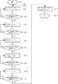
図1は、本発明の第1の実施形態におけるフィルタ洗浄装置を説明する図である。1は制御装置を含む工作機械本体、2はダーティータンク、3はクリーンタンク、4はダーティーポンプ、5は切削液の流れから見てダーティーポンプの後ろに設けられた逆止弁、6は逆洗フィルタ容器であり、ダーティーポンプ4からの切削液が流入する流入口6a、濾過時に切削液が流出し、逆洗時にエアが流入する開口6b、逆洗時にエアや切削液が排出する排出口6cが備えられており、内部には7の逆洗フィルタが設けられている。8は逆洗排出バルブ、11はクリーンタンクバルブ、12はエア源、13はエア供給バルブ、14はエアの流れから見てエア供給バルブの後ろに設けられた逆止弁、15は切削液供給ポンプである。Hereinafter, embodiments of the present invention will be described with reference to the drawings.
(First embodiment)
FIG. 1 is a diagram illustrating a filter cleaning device according to a first embodiment of the present invention. 1 is a machine tool body including a control device, 2 is a dirty tank, 3 is a clean tank, 4 is a dirty pump, 5 is a check valve provided behind the dirty pump as viewed from the flow of cutting fluid, and 6 is backwashed An
工作機械本体1においては、内部の制御装置によって制御されて図示しないワークを加工する。工作機械本体1を制御する内部の制御装置によって制御される切削液供給ポンプ15によって、クリーンタンク3に貯留された濾過された切削液が工作機械本体1に供給される。切削液は、ワーク加工において使用された後に、管路17を介してダーティータンク2に回収される。
工作機械本体1内部の制御装置は、工作機械本体1の制御とともに、図1に点線で示されているように、ダーティーポンプ4やエア源12の駆動動作、逆洗排出バルブ8、クリーンタンクバルブ11、エア供給バルブ13の開閉制御も行っている。In the machine tool
The control device inside the machine tool
まずは、工作機械における不純物を含んだ切削液の濾過について説明する。タンクは、ダーティータンク2とクリーンタンク3とから構成される。ダーティータンク2には工作機械本体1から回収された切削液が貯留されており、この切削液には切粉やスラッジなどの不純物が混入している。ダーティーポンプ4は、ダーティータンク2に貯留された不純物を含んだ切削液をくみ上げ、流入口6aを通じて逆洗フィルタ容器6に供給する。逆洗フィルタ容器6には、切削液中に混入した切粉やスラッジなどの不純物を除去するための逆洗フィルタ7が内部に設けられている。また、ダーティーポンプ4と逆洗フィルタ容器6との間には、逆洗フィルタ容器6からの切削液及び後述する圧縮エアがダーティーポンプ4側へ逆流することを防ぐために逆止弁5が設けられている。また、排出口とダーティータンク2との間には逆洗排出バルブ8が、流出口とクリーンタンク3との間にはクリーンタンクバルブ11が備えられている。 First, filtration of cutting fluid containing impurities in a machine tool will be described. The tank is composed of a
不純物を含んだ切削液を濾過するときには、クリーンタンクバルブ11が開状態、逆洗排出バルブ8が閉状態、エア供給バルブ13が閉状態に制御され、切削液は、ダーティータンク2、ダーティーポンプ4によりくみ上げられ、逆止弁5から流入口6aを通じて逆洗フィルタ容器6(逆洗フィルタ7)に供給され、逆洗フィルタ7において切粉、スラッジなどの不純物を除去した後、開口6bを通じてクリーンタンクバルブ11からクリーンタンク3へと排出される。なお、逆洗フィルタ容器6内の逆洗フィルタにおける切削液の流れについては、従来公知の構成であるため説明を省略する。
クリーンタンク3には、図示しない液面高さ検出用のセンサーが設けられており、液面が低下したときにダーティーポンプ4が作動して、逆洗フィルタにおいて切削液の濾過を行った後に、クリーンタンク3に切削液が供給される。When the cutting fluid containing impurities is filtered, the
The
切粉やスラッジ等の不純物を除去する逆洗フィルタ容器6内の逆洗フィルタ7は、性能の維持や寿命の延長を目的として、逆洗フィルタ7に付着した切粉やスラッジを取り除く洗浄動作を行うことがある。逆洗フィルタ7の洗浄動作の一例として逆洗動作がある。
図1に基づいて逆洗動作の方法を説明すると、洗浄を行う逆洗フィルタ7が装着された逆洗フィルタ容器6の流入側の逆止弁5及び流出側のクリーンタンクバルブ11を閉じ、逆洗フィルタ容器6の中に残っている切削液が移動できないようにしておき、続いてエア源12に接続されたエア供給バルブ13と逆止弁14を開き、開口6bを通じて逆洗フィルタ容器6内に通常時の切削液の流れ方向とは逆の方向に圧縮空気を供給し、逆洗排出バルブ8を開くことによって、圧縮空気によって加圧された切削液が通常時の切削液の流れ方向とは逆の方向に逆洗フィルタ容器6内を通過した後、排出口6cを通じて逆洗排出バルブ8を通過してダーティータンク2に戻る。この切削液の流れにより、逆洗フィルタ7に付着した切粉やスラッジなどの不純物を除去することができる。The backwash filter 7 in the
The backwashing operation method will be described with reference to FIG. 1. The
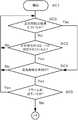
本実施形態においては、逆洗を行なう際、圧縮空気をフィルタ内に供給する動作と排出管路を開く動作の間に一定の間隔を置いて、フィルタ内又は、フィルタ内及びフィルタ容器内の圧力が圧縮空気の供給圧と等しくなるまで保持し、その後排出管路を開く制御を行っている。具体的な動作を、図2及び図3に基づいて説明する。図2は、本発明の第1の実施形態のフィルタ洗浄装置における逆洗動作の処理を説明するフローチャートであり、図3は、フィルタ洗浄装置の動作を説明するタイミングチャートの一例である。あらかじめ、圧縮空気の供給を開始してから、フィルタ内又は、フィルタ内及びフィルタ容器内の圧力が圧縮空気の供給圧と略等しくなる時間を求めて工作機械本体1内部の制御装置に設定しておき、その時間を後述の内圧上昇時間(PRM2)として設定する。この時間は、機械の設置環境や使用条件によって異なることがあるため可変として、機械の設置環境や使用条件が変更されたときに設定するようにすることが望ましい。以下に、図3のタイミングチャートを参照にしながら、図2のフローチャートをステップ毎に説明する。 In the present embodiment, when backwashing is performed, the pressure in the filter or in the filter and the filter container is set at a certain interval between the operation of supplying compressed air into the filter and the operation of opening the discharge pipe. Is maintained until it becomes equal to the supply pressure of the compressed air, and then the discharge pipe is opened. A specific operation will be described with reference to FIGS. FIG. 2 is a flowchart for explaining the process of backwashing operation in the filter cleaning apparatus according to the first embodiment of the present invention, and FIG. 3 is an example of a timing chart for explaining the operation of the filter cleaning apparatus. After the supply of compressed air is started in advance, the time in which the pressure in the filter or in the filter and the filter container is substantially equal to the supply pressure of the compressed air is obtained and set in the control device inside the
・(ステップSA1)逆洗動作の開始。
・(ステップSA2)ダーティーポンプ4をオフにして切削液の供給を停止し、クリーンタンクバルブ11をオンにして閉状態とする。これによって、逆洗フィルタ容器6への切削液の流入及び流出を停止して、逆洗用エアが供給されるまで待機する。
・(ステップSA3)逆洗準備期間(PRM1)が経過したかどうかを判定し、経過していない場合はステップSA2に戻り、経過した場合はステップSA4に進む。
・(ステップSA4)エア供給バルブ13をオンにして、エア源12からのエアを供給する。このとき、逆止弁5、逆洗排出バルブ8、クリーンタンクバルブ11はいずれも閉状態であるため、エア源12から供給されるエアによって、逆洗フィルタ容器6内の圧力が高められる。
・(ステップSA5)あらかじめ求めて設定されている内圧上昇時間(PRM2)が経過したかどうかを判定する。経過していない場合は、ステップSA4に戻り、経過した場合は逆洗フィルタ7内及び逆洗フィルタ容器6内の圧力が圧縮空気の供給圧と略等しくなったと判定してステップSA6に進む。(Step SA1) Start of backwashing operation.
(Step SA2) The
(Step SA3) It is determined whether the backwash preparation period (PRM1) has elapsed. If not, the process returns to Step SA2, and if it has elapsed, the process proceeds to Step SA4.
(Step SA4) The
(Step SA5) It is determined whether or not the internal pressure increase time (PRM2) determined and set in advance has elapsed. If it has not elapsed, the process returns to step SA4. If it has elapsed, it is determined that the pressure in the backwash filter 7 and the
・(ステップSA6)逆洗排出バルブ8をオンにしてエアが流れる状態とする。これにより、エア源12から供給されるエアによって逆洗フィルタ7の逆洗が行われる(エア逆洗)。
・(ステップSA7)エア逆洗時間(PRM3)が経過したかどうかを判定し、経過していない場合はステップSA6に戻り、経過した場合はステップSA8に進む。
・(ステップSA8)ダーティーポンプ4をオンにして切削液の供給を開始し、同時にエア供給バルブ13をオフにして、エア源12からのエアの供給を停止する。これにより、エアに代わって、ダーティーポンプ4から供給される切削液によって逆洗フィルタ7の逆洗が行われる。
・(ステップSA9)切削液逆洗時間(PRM4)が経過したかどうかを判定し、経過していない場合はステップSA8に戻り、経過した場合はステップSA10に進む。(Step SA6) The backwash discharge valve 8 is turned on so that air flows. Thereby, the backwashing filter 7 is backwashed by the air supplied from the air source 12 (air backwashing).
(Step SA7) It is determined whether the air backwash time (PRM3) has elapsed. If not, the process returns to Step SA6, and if it has elapsed, the process proceeds to Step SA8.
(Step SA8) The
(Step SA9) It is determined whether or not the cutting fluid backwash time (PRM4) has elapsed. If not, the process returns to Step SA8, and if it has elapsed, the process proceeds to Step SA10.
・(ステップSA10)ダーティーポンプ4をオフにして切削液の供給を停止する。これにより、切削液の供給は停止されるが逆洗排出バルブ8は開状態であるため、逆洗フィルタ容器6内の切粉と切削液が除去される。
・(ステップSA11)加工準備時間(PRM5)が経過したかどうかを判定し、経過していない場合はステップSA10に戻り、経過した場合はステップSA12に進む。
・(ステップSA12)逆洗排出バルブ8をオフにして、エア及び切削液が流れない状態とし、同時にクリーンタンクバルブ11をオフにして切削液が流れる状態として、ダーティータンク2からクリーンタンク3への切削液の供給が行える状態とする。
・(ステップSA13)逆洗動作終了。(Step SA10) The
(Step SA11) It is determined whether or not the processing preparation time (PRM5) has elapsed. If not, the process returns to Step SA10, and if it has elapsed, the process proceeds to Step SA12.
(Step SA12) The backwash discharge valve 8 is turned off to prevent air and cutting fluid from flowing, and at the same time, the
(Step SA13) End of the backwash operation.
本実施形態における工作機械本体1内部の制御装置が、本願発明における設定手段、計時手段、不純物排出実施手段に相当する。 The control device inside the machine tool
なお、本実施形態においては、内圧上昇時間(PRM2)の設定を、逆洗フィルタ内及び逆洗フィルタ容器内の圧力がエア源から供給される圧縮空気の供給圧と略等しくなる時間として設定しているが、必ずしも完全に等しくなる時間に設定しなくともよく、ある程度の許容範囲であれば、圧縮空気の供給圧と異なる圧力になる時間に設定してもよい。 In this embodiment, the setting of the internal pressure increase time (PRM2) is set as the time during which the pressure in the backwash filter and the backwash filter container is substantially equal to the supply pressure of the compressed air supplied from the air source. However, it is not always necessary to set the time to be completely equal, and may be set to a time when the pressure is different from the supply pressure of the compressed air as long as it is within a certain allowable range.
(第2の実施形態)
図4は、本発明の第2の実施形態におけるフィルタ洗浄装置を説明する図である。第1の実施形態と同一の構成については同一の符号を付与している。本実施形態における第1の実施形態からの相違点は、逆洗フィルタ容器6とクリーンタンクバルブ11との間の配管経路に、逆洗フィルタ7内又は逆洗フィルタ7内及び逆洗フィルタ容器6内の圧力を検出する圧力計16を備えた点である。(Second Embodiment)
FIG. 4 is a diagram illustrating a filter cleaning device according to the second embodiment of the present invention. The same code | symbol is provided about the structure same as 1st Embodiment. The difference of the present embodiment from the first embodiment is that the backwash filter 7 or the backwash filter 7 and the
本実施形態においては、逆洗を行なう際、圧力計16によって逆洗フィルタ7内又は、逆洗フィルタ7内及び逆洗フィルタ容器6内の圧力を検出して、それらが圧縮空気の供給圧と等しくなった後に排出管路を開く制御を行っている。具体的な動作を、図5に基づいて説明する。図5は、本発明の第2の実施形態のフィルタ洗浄装置における逆洗動作の処理を説明するフローチャートである。
図5のフローチャートは、第1の実施形態における逆洗動作の処理を説明する図2のフローチャートと概ね同じ動作を行うが、図2におけるステップSA5の動作のみが異なっている。以下、第1の実施形態と相違しているステップSA5’について説明する。
・(ステップSA5’)逆洗フィルタ7内又は、逆洗フィルタ7内及び逆洗フィルタ容器6内の圧力が圧縮空気の供給圧と等しくなったかどうかを判定する。等しくなっていない場合は、ステップSA4に戻り、等しくなった場合はステップSA6に進む。In this embodiment, when performing backwashing, the
The flowchart of FIG. 5 performs substantially the same operation as the flowchart of FIG. 2 for explaining the processing of the backwashing operation in the first embodiment, but only the operation of step SA5 in FIG. 2 is different. Hereinafter, step SA5 ′ that is different from the first embodiment will be described.
(Step SA5 ′) It is determined whether the pressure in the backwash filter 7 or in the backwash filter 7 and the
なお、本実施形態においても、ステップSA5’における判定を逆洗フィルタ7内及び逆洗フィルタ容器6内の圧力がエア源12から供給される圧縮空気の供給圧と略等しくなったことで判定しているが、必ずしも完全に等しくなることで判定しなくともよく、ある程度の許容範囲であれば、圧縮空気の供給圧と等しくなる前に逆洗排出バルブ8をオンとするようにしてもよい。 Also in this embodiment, the determination in step SA5 ′ is determined by the fact that the pressure in the backwash filter 7 and the
(変形例1)
図6は、本発明の変形例1におけるフィルタ洗浄装置を説明する図であり、第1の実施形態におけるフィルタ洗浄装置の変形例である。第1の実施形態と同一の構成については同一の符号を付与している。本変形例における第1の実施形態からの相違点は、逆洗フィルタ容器6とクリーンタンクバルブ11との間に、ラインフィルタ10を内部に備えたラインフィルタ容器9を備えた点である。ラインフィルタ10は逆洗フィルタ7に比べて目が細かいフィルタが用いられており、切削液の供給にあたって、逆洗フィルタ7で濾過した切削液を、さらに目が細かいラインフィルタ10で濾過することによって、クリーンタンク3に供給する切削液の濾過性能を向上させることができる。
なお、図6においては、第1の実施形態にラインフィルタ容器9及びラインフィルタ10を備えた例で説明したが、第2の実施形態の圧力計16を備えたフィルタ洗浄装置にも、同様にラインフィルタ容器9及びラインフィルタ10を備える構成とすることもできる。(Modification 1)
FIG. 6 is a diagram illustrating the filter cleaning device according to the first modification of the present invention, which is a modification of the filter cleaning device according to the first embodiment. The same code | symbol is provided about the structure same as 1st Embodiment. The difference from the first embodiment in this modification is that a line filter container 9 having a
In FIG. 6, the example in which the line filter container 9 and the
(変形例2)
図7は、本発明の変形例2における動作処理を説明するフローチャートである。第1の実施形態及び第2の実施形態においては、逆洗動作の処理開始からの処理のみ説明していたが、本変形例は、第1の実施形態及び第2の実施形態において、そのような逆洗動作に入る前の逆洗機構のチェックや、強制的な逆洗動作への移行処理についての動作処理を追加する動作である。以下に、図7のフローチャートのステップ毎に説明する。
・(ステップSC1)動作開始。
・(ステップSC2)前回の逆洗動作から、あらかじめ定められた所定の逆洗間隔時間が経過しているかどうかを判定する。経過している場合はステップSC4に進み、経過していない場合はステップSC3に進む。
・(ステップSC3)強制的に逆洗動作を行う指令のMコードが指定されているかどうかを判定する。Mコードが指定されている場合にはステップSC4に進み、指定されていない場合は、ステップSC2に戻る。
・(ステップSC4)逆洗機能が有効かどうかを判定する。具体的には、逆洗機能が有効でない場合に立つフラグやチェックビットによって判定する。有効である場合にはステップSC5に進み、有効でない場合にはステップSC2に戻る。
・(ステップSC5)逆洗機能に不具合が発生している旨のアラームが出ているかどうかを判定する。アラームが出ている場合にはステップSC2に戻り、出ていない場合はJ1に進む。
J1に進んだ後は、第1の実施形態の図2のJ1又は第2の実施形態の図5のJ1に進み、それぞれステップSA2から動作を実行する。(Modification 2)
FIG. 7 is a flowchart for explaining the operation processing in the second modification of the present invention. In the first embodiment and the second embodiment, only the process from the start of the process of the backwash operation has been described, but this modification example is similar to the first embodiment and the second embodiment. This is an operation for adding an operation process for checking the backwashing mechanism before entering the backwashing operation and for shifting to the forced backwashing operation. Below, it demonstrates for every step of the flowchart of FIG.
(Step SC1) Operation starts.
(Step SC2) It is determined whether or not a predetermined backwash interval time determined in advance has elapsed since the previous backwash operation. If it has elapsed, the process proceeds to step SC4, and if it has not elapsed, the process proceeds to step SC3.
(Step SC3) It is determined whether or not the M code of the command for forcibly performing the backwash operation is designated. If the M code is designated, the process proceeds to step SC4. If not designated, the process returns to step SC2.
(Step SC4) It is determined whether the backwash function is effective. Specifically, it is determined by a flag or check bit that stands when the backwash function is not effective. If it is valid, the process proceeds to step SC5, and if it is not valid, the process returns to step SC2.
(Step SC5) It is determined whether an alarm indicating that a problem has occurred in the backwash function has been issued. If an alarm has been issued, the process returns to step SC2, and if not, the process proceeds to J1.
After proceeding to J1, the process proceeds to J1 of FIG. 2 of the first embodiment or J1 of FIG. 5 of the second embodiment, and the operation is executed from step SA2.
これらの実施形態によって、圧縮空気の供給圧と逆洗フィルタ7内又は、逆洗フィルタ7内及び逆洗フィルタ容器6内の圧力が等しくなるようにしてから排出管路を開くようにすることによって、逆洗フィルタ7に圧縮空気の供給圧が十分にかかり、圧縮空気の流入により押しのけられて逆洗フィルタ7の内部から外に向かって流れる切削液の流速と圧力が最大となり、フィルタ表面に付着した切粉を除去する効果を大きくすることができる。 By these embodiments, the supply pressure of compressed air and the pressure in the backwash filter 7 or the pressure in the backwash filter 7 and the
なお、これらの実施形態においては、逆洗期間前半の洗浄にエア源からの圧縮空気を用いて行っているが、圧縮空気ではなく、液体を用いて逆洗を行ってもよい。 In these embodiments, cleaning in the first half of the backwashing period is performed using compressed air from an air source. However, backwashing may be performed using liquid instead of compressed air.
1 工作機械本体
2 ダーティータンク
3 クリーンタンク
4 ダーティーポンプ
5 逆止弁
6 逆洗フィルタ容器
6a 流入口
6b 開口
6c 排出口
7 逆洗フィルタ
8 逆洗排出バルブ
9 ラインフィルタ容器
10 ラインフィルタ
11 クリーンタンクバルブ
12 エア源
13 エア供給バルブ
14 逆止弁
15 切削液供給ポンプ
16 圧力計
17 管路
110 タンク
111 ダーティーポンプ
112 流入側バルブ
113 フィルタ容器
114 差圧スイッチ
115 排出バルブ
116 エア源
117 エア供給バルブ
118 流出側バルブ
119 切削液
120,121,122,123 管路
170 工作機械本体DESCRIPTION OF
Claims (2)
Translated fromJapanese圧縮空気又は切削液が前記開口から供給され、前記フィルタ容器の排出口に設けた弁を開くことにより圧縮空気又は切削液が流れて、前記濾過した不純物をフィルタから除去する逆洗浄機能を有する切削液濾過装置を備えた工作機械において、
前記フィルタ容器へ圧縮空気又は切削液の供給を開始してから前記フィルタ容器の排出口に設けられた弁を開放するまでの時間を設定する設定手段と、
前記フィルタ容器への前記圧縮空気又は切削液の供給開始からの時間を計時する計時手段と、
前記計時手段が前記設定手段が設定した設定時間を計時した後に、前記フィルタ容器の排出口に設けられた弁を開放する不純物排出実施手段と、
を有することを特徴とするフィルタ洗浄装置を備えた工作機械。Supplying a cutting fluid containing impurities to a filter container containing a filter, the cutting fluid flows from the inlet of the filter container, and the impurities are filtered by a filter by flowing out from the opening of the filter container;
Cutting having a back cleaning function in which compressed air or cutting fluid is supplied from the opening and compressed air or cutting fluid flows by opening a valve provided at the outlet of the filter container to remove the filtered impurities from the filter. In machine tools equipped with liquid filtration devices,
Setting means for setting a time from the start of supplying compressed air or cutting fluid to the filter container until the valve provided at the outlet of the filter container is opened;
Time measuring means for measuring time from the start of supply of the compressed air or cutting fluid to the filter container;
Impurity discharge performing means for opening a valve provided at the discharge port of the filter container after the time measuring means has timed the set time set by the setting means;
A machine tool provided with a filter cleaning device.
圧縮空気又は切削液が前記開口から供給され、前記フィルタ容器の排出口に設けた弁を開くことにより圧縮空気又は切削液が流れて、前記濾過した不純物をフィルタから除去する逆洗浄機能を有する切削液濾過装置を備えた工作機械において、
前記フィルタの内部または前記フィルタ容器の内部の圧力を検出し、制御装置にフィードバックする圧力検出装置と、
前記圧力検出装置で検出した圧力が前記圧縮空気又は切削液の供給圧と略等しくなった時、前記フィルタ容器の排出口に設けられた弁を開放する不純物排出実施手段と、
を有することを特徴とするフィルタ洗浄装置を備えた工作機械。Supplying a cutting fluid containing impurities to a filter container containing a filter, the cutting fluid flows from the inlet of the filter container, and the impurities are filtered by a filter by flowing out from the opening of the filter container;
Cutting having a back cleaning function in which compressed air or cutting fluid is supplied from the opening and compressed air or cutting fluid flows by opening a valve provided at the outlet of the filter container to remove the filtered impurities from the filter. In machine tools equipped with liquid filtration devices,
A pressure detection device for detecting the pressure inside the filter or the filter container and feeding back to the control device;
Impurity discharge performing means for opening a valve provided at the discharge port of the filter container when the pressure detected by the pressure detection device becomes substantially equal to the supply pressure of the compressed air or cutting fluid;
A machine tool provided with a filter cleaning device.
Priority Applications (4)
| Application Number | Priority Date | Filing Date | Title |
|---|---|---|---|
| JP2012228335AJP2014079829A (en) | 2012-10-15 | 2012-10-15 | Machine tool including filter cleaning device |
| DE102013111103.3ADE102013111103A1 (en) | 2012-10-15 | 2013-10-08 | Machine tool with a filter device for the cutting fluid |
| CN201310479284.2ACN103722446A (en) | 2012-10-15 | 2013-10-14 | Machine tool equipped with cutting fluid filtering device |
| US14/054,756US20140102964A1 (en) | 2012-10-15 | 2013-10-15 | Machine tool equipped with cutting fluid filtering device |
Applications Claiming Priority (1)
| Application Number | Priority Date | Filing Date | Title |
|---|---|---|---|
| JP2012228335AJP2014079829A (en) | 2012-10-15 | 2012-10-15 | Machine tool including filter cleaning device |
Publications (1)
| Publication Number | Publication Date |
|---|---|
| JP2014079829Atrue JP2014079829A (en) | 2014-05-08 |
Family
ID=50383341
Family Applications (1)
| Application Number | Title | Priority Date | Filing Date |
|---|---|---|---|
| JP2012228335APendingJP2014079829A (en) | 2012-10-15 | 2012-10-15 | Machine tool including filter cleaning device |
Country Status (4)
| Country | Link |
|---|---|
| US (1) | US20140102964A1 (en) |
| JP (1) | JP2014079829A (en) |
| CN (1) | CN103722446A (en) |
| DE (1) | DE102013111103A1 (en) |
Families Citing this family (13)
| Publication number | Priority date | Publication date | Assignee | Title |
|---|---|---|---|---|
| CN104841193A (en)* | 2015-04-24 | 2015-08-19 | 戴杰磨床集团股份有限公司 | Cemented carbide cooling and filtering apparatus with gas storage device |
| CN105415083A (en)* | 2015-12-20 | 2016-03-23 | 重庆德蒙特科技发展有限公司 | Gas supplementing device for cutting fluid |
| CN107414592A (en)* | 2017-08-30 | 2017-12-01 | 深圳市圆梦精密技术研究院 | Digit Control Machine Tool cooling recirculation system |
| CN110478959A (en)* | 2018-05-15 | 2019-11-22 | 秦文隆 | Nonmetallic materials element device for filtering cutting fluid |
| US12179299B2 (en)* | 2018-08-07 | 2024-12-31 | Illinois Tool Works Inc. | Machine tool with recirculating coolant filtration system |
| CN109015105B (en)* | 2018-10-16 | 2025-01-10 | 尤洛卡(山东)矿业科技有限公司 | A cutting fluid management system |
| CN109746759B (en)* | 2019-03-25 | 2020-07-24 | 温州凯唐电子科技有限公司 | Cutting fluid cooling device for numerical control machine tool |
| US12403539B2 (en)* | 2020-09-16 | 2025-09-02 | Illinois Tool Works Inc. | Standpipe recirculation systems for material removal machines |
| CN113182920A (en)* | 2021-04-12 | 2021-07-30 | 沈阳环境科学研究院 | Comprehensive wastewater recycling system |
| CN113414636A (en)* | 2021-05-28 | 2021-09-21 | 陈怀贵 | Inside iron fillings of cutting fluid and dust treatment facility for horizontal machining center |
| CN113478293A (en)* | 2021-06-03 | 2021-10-08 | 陈怀贵 | Circulating pipeline equipment for purifying cutting fluid for horizontal machining center |
| CN118699435B (en)* | 2024-08-30 | 2024-10-29 | 溧阳市兴达机械有限公司 | A metal roller inner wall punching device |
| CN119318830B (en)* | 2024-12-18 | 2025-03-25 | 浙江吉宝智能装备股份有限公司 | A machine tool chip filtering and processing device and method |
Citations (6)
| Publication number | Priority date | Publication date | Assignee | Title |
|---|---|---|---|---|
| JPH01500732A (en)* | 1986-07-11 | 1989-03-16 | メムテック・リミテッド | Cleaning the filter |
| JPH08197536A (en)* | 1995-01-27 | 1996-08-06 | Noritake Co Ltd | Method and device for regenerating waste working fluid |
| JP2000237511A (en)* | 1999-02-17 | 2000-09-05 | Dainippon Ink & Chem Inc | Accumulator type automatic backwashing device |
| JP2006272474A (en)* | 2005-03-28 | 2006-10-12 | Brother Ind Ltd | Machine tool controller |
| JP2008284464A (en)* | 2007-05-18 | 2008-11-27 | Nksyst Co Ltd | Filtering method and apparatus therefor with excellent intermittent backwashing |
| JP2011104488A (en)* | 2009-11-13 | 2011-06-02 | Central Filter Mfg Co Ld | Washing method of filtration apparatus |
Family Cites Families (5)
| Publication number | Priority date | Publication date | Assignee | Title |
|---|---|---|---|---|
| JPS60104212A (en) | 1983-11-11 | 1985-06-08 | Koito Mfg Co Ltd | Electromagnetic counter type running distance meter |
| JPS62201620A (en) | 1986-02-28 | 1987-09-05 | Kirin Brewery Co Ltd | Backwash device for filtration equipment using filter aid |
| AU6687496A (en)* | 1995-07-27 | 1997-02-26 | Pall Corporation | Hybrid filter system and method for filtering process fluid |
| JP2001252847A (en) | 2000-03-06 | 2001-09-18 | Taisei Kogyo Kk | Working fluid filtering device |
| JP4797409B2 (en) | 2005-03-17 | 2011-10-19 | ブラザー工業株式会社 | Coolant filtration device |
- 2012
- 2012-10-15JPJP2012228335Apatent/JP2014079829A/enactivePending
- 2013
- 2013-10-08DEDE102013111103.3Apatent/DE102013111103A1/ennot_activeWithdrawn
- 2013-10-14CNCN201310479284.2Apatent/CN103722446A/enactivePending
- 2013-10-15USUS14/054,756patent/US20140102964A1/ennot_activeAbandoned
Patent Citations (6)
| Publication number | Priority date | Publication date | Assignee | Title |
|---|---|---|---|---|
| JPH01500732A (en)* | 1986-07-11 | 1989-03-16 | メムテック・リミテッド | Cleaning the filter |
| JPH08197536A (en)* | 1995-01-27 | 1996-08-06 | Noritake Co Ltd | Method and device for regenerating waste working fluid |
| JP2000237511A (en)* | 1999-02-17 | 2000-09-05 | Dainippon Ink & Chem Inc | Accumulator type automatic backwashing device |
| JP2006272474A (en)* | 2005-03-28 | 2006-10-12 | Brother Ind Ltd | Machine tool controller |
| JP2008284464A (en)* | 2007-05-18 | 2008-11-27 | Nksyst Co Ltd | Filtering method and apparatus therefor with excellent intermittent backwashing |
| JP2011104488A (en)* | 2009-11-13 | 2011-06-02 | Central Filter Mfg Co Ld | Washing method of filtration apparatus |
Also Published As
| Publication number | Publication date |
|---|---|
| CN103722446A (en) | 2014-04-16 |
| DE102013111103A1 (en) | 2014-04-17 |
| US20140102964A1 (en) | 2014-04-17 |
Similar Documents
| Publication | Publication Date | Title |
|---|---|---|
| JP2014079829A (en) | Machine tool including filter cleaning device | |
| JP5674847B2 (en) | Machine tool with cutting fluid filtration device | |
| JP5580388B2 (en) | Machine tool with filter cleaning device | |
| JP6041380B2 (en) | Processing fluid purification system | |
| JP5339957B2 (en) | Coolant supply device | |
| CN102989223A (en) | Automatic backwash filtering device | |
| KR101531599B1 (en) | Back washing type water purifier | |
| JP5302431B2 (en) | Filter used for impurity filtering device and machine tool equipped with impurity filtering device | |
| CN207237393U (en) | A kind of water treatment system with backwashing function | |
| CN101301584A (en) | Tube-type sewage water micro-filter processing equipment | |
| WO2010026476A3 (en) | Method and device for cleaning a filter for fluids | |
| CN203436889U (en) | Checking, guiding and filtering device | |
| CN101730577B (en) | How the water purifier works | |
| KR100644241B1 (en) | Chip filtration device for cutting oil and its backwashing method | |
| JP7179285B2 (en) | Tooling fluid supply system | |
| KR20020084663A (en) | Auto clean filter | |
| CN209771563U (en) | Cutting fluid filtration system | |
| CN107265570A (en) | A kind of automatic back-washing water purifier | |
| CN110015718A (en) | For handling Spent Radioactive water purifying means | |
| JP5005165B2 (en) | Water treatment method | |
| US20130180908A1 (en) | Filter Backflush System for Entrained Filtration Elements | |
| KR100885215B1 (en) | Cooling water filtration device | |
| JP2006082031A (en) | Y-strainer | |
| KR100489438B1 (en) | Method for treating waste water generated in a semiconductor manufacturing process | |
| CN223184235U (en) | Circulation pipeline of a sampling device |
Legal Events
| Date | Code | Title | Description |
|---|---|---|---|
| A871 | Explanation of circumstances concerning accelerated examination | Free format text:JAPANESE INTERMEDIATE CODE: A871 Effective date:20140227 | |
| A975 | Report on accelerated examination | Free format text:JAPANESE INTERMEDIATE CODE: A971005 Effective date:20140416 | |
| A131 | Notification of reasons for refusal | Free format text:JAPANESE INTERMEDIATE CODE: A131 Effective date:20140422 | |
| A131 | Notification of reasons for refusal | Free format text:JAPANESE INTERMEDIATE CODE: A131 Effective date:20140902 | |
| A02 | Decision of refusal | Free format text:JAPANESE INTERMEDIATE CODE: A02 Effective date:20150106 |