JP2014076227A - Forceps device - Google Patents
Forceps deviceDownload PDFInfo
- Publication number
- JP2014076227A JP2014076227AJP2012226552AJP2012226552AJP2014076227AJP 2014076227 AJP2014076227 AJP 2014076227AJP 2012226552 AJP2012226552 AJP 2012226552AJP 2012226552 AJP2012226552 AJP 2012226552AJP 2014076227 AJP2014076227 AJP 2014076227A
- Authority
- JP
- Japan
- Prior art keywords
- unit
- rotation operation
- outer casing
- forceps
- inner cable
- Prior art date
- Legal status (The legal status is an assumption and is not a legal conclusion. Google has not performed a legal analysis and makes no representation as to the accuracy of the status listed.)
- Granted
Links
Images


Classifications
- A—HUMAN NECESSITIES
- A61—MEDICAL OR VETERINARY SCIENCE; HYGIENE
- A61B—DIAGNOSIS; SURGERY; IDENTIFICATION
- A61B17/00—Surgical instruments, devices or methods
- A61B17/28—Surgical forceps
- A61B17/2812—Surgical forceps with a single pivotal connection
- A61B17/282—Jaws
- A—HUMAN NECESSITIES
- A61—MEDICAL OR VETERINARY SCIENCE; HYGIENE
- A61B—DIAGNOSIS; SURGERY; IDENTIFICATION
- A61B18/00—Surgical instruments, devices or methods for transferring non-mechanical forms of energy to or from the body
- A61B18/04—Surgical instruments, devices or methods for transferring non-mechanical forms of energy to or from the body by heating
- A61B18/12—Surgical instruments, devices or methods for transferring non-mechanical forms of energy to or from the body by heating by passing a current through the tissue to be heated, e.g. high-frequency current
- A61B18/14—Probes or electrodes therefor
- A61B18/1442—Probes having pivoting end effectors, e.g. forceps
- A61B18/1445—Probes having pivoting end effectors, e.g. forceps at the distal end of a shaft, e.g. forceps or scissors at the end of a rigid rod
- A—HUMAN NECESSITIES
- A61—MEDICAL OR VETERINARY SCIENCE; HYGIENE
- A61B—DIAGNOSIS; SURGERY; IDENTIFICATION
- A61B18/00—Surgical instruments, devices or methods for transferring non-mechanical forms of energy to or from the body
- A61B18/04—Surgical instruments, devices or methods for transferring non-mechanical forms of energy to or from the body by heating
- A61B18/12—Surgical instruments, devices or methods for transferring non-mechanical forms of energy to or from the body by heating by passing a current through the tissue to be heated, e.g. high-frequency current
- A61B18/14—Probes or electrodes therefor
- A61B18/1492—Probes or electrodes therefor having a flexible, catheter-like structure, e.g. for heart ablation
- A—HUMAN NECESSITIES
- A61—MEDICAL OR VETERINARY SCIENCE; HYGIENE
- A61B—DIAGNOSIS; SURGERY; IDENTIFICATION
- A61B17/00—Surgical instruments, devices or methods
- A61B17/28—Surgical forceps
- A61B17/29—Forceps for use in minimally invasive surgery
- A61B2017/2926—Details of heads or jaws
- A61B2017/2927—Details of heads or jaws the angular position of the head being adjustable with respect to the shaft
- A61B2017/2929—Details of heads or jaws the angular position of the head being adjustable with respect to the shaft with a head rotatable about the longitudinal axis of the shaft
- A—HUMAN NECESSITIES
- A61—MEDICAL OR VETERINARY SCIENCE; HYGIENE
- A61B—DIAGNOSIS; SURGERY; IDENTIFICATION
- A61B18/00—Surgical instruments, devices or methods for transferring non-mechanical forms of energy to or from the body
- A61B2018/00571—Surgical instruments, devices or methods for transferring non-mechanical forms of energy to or from the body for achieving a particular surgical effect
- A61B2018/00577—Ablation
- A—HUMAN NECESSITIES
- A61—MEDICAL OR VETERINARY SCIENCE; HYGIENE
- A61B—DIAGNOSIS; SURGERY; IDENTIFICATION
- A61B18/00—Surgical instruments, devices or methods for transferring non-mechanical forms of energy to or from the body
- A61B2018/00982—Surgical instruments, devices or methods for transferring non-mechanical forms of energy to or from the body combined with or comprising means for visual or photographic inspections inside the body, e.g. endoscopes
Landscapes
- Health & Medical Sciences (AREA)
- Surgery (AREA)
- Life Sciences & Earth Sciences (AREA)
- Engineering & Computer Science (AREA)
- Biomedical Technology (AREA)
- Public Health (AREA)
- Nuclear Medicine, Radiotherapy & Molecular Imaging (AREA)
- Veterinary Medicine (AREA)
- General Health & Medical Sciences (AREA)
- Heart & Thoracic Surgery (AREA)
- Medical Informatics (AREA)
- Molecular Biology (AREA)
- Animal Behavior & Ethology (AREA)
- Physics & Mathematics (AREA)
- Otolaryngology (AREA)
- Plasma & Fusion (AREA)
- Ophthalmology & Optometry (AREA)
- Surgical Instruments (AREA)
Abstract
Translated fromJapaneseDescription
Translated fromJapanese本発明は、鉗子装置に関する。さらに詳しくは、操作性が良く、ケーブル接続部分における磨耗のおそれがない、耐久性の良い鉗子装置に関する。 The present invention relates to a forceps device. More specifically, the present invention relates to a forceps device that has good operability and has no fear of abrasion at a cable connection portion, and has good durability.
従来、体腔内にできた患部等を把持するために、内視鏡を介して体内に挿入される鉗子装置が用いられてきた。このような鉗子装置は、患部を把持するための開閉可能な一対の鉗子片を有している。この鉗子片は、医師等が操作する手元側の操作部の操作力を、操作ワイヤにより伝達して、操作部から離れた患部において鉗子片を開閉し、患部を把持する。しかしながら、体腔内の患部において、鉗子片の開閉方向が患部の位置に対して適切でない場合がある。そのため、鉗子片を回転させる機構を備えた鉗子装置が用いられている。 Conventionally, a forceps device that is inserted into a body via an endoscope has been used in order to grasp an affected part or the like formed in a body cavity. Such a forceps device has a pair of forceps pieces that can be opened and closed for gripping the affected area. The forceps piece transmits the operating force of the operation portion on the proximal side operated by a doctor or the like through an operation wire, opens and closes the forceps piece at the affected portion away from the operating portion, and holds the affected portion. However, in the affected part in the body cavity, the opening and closing direction of the forceps piece may not be appropriate with respect to the position of the affected part. Therefore, a forceps device having a mechanism for rotating a forceps piece is used.
このような鉗子片を回転させる機構として、特許文献1に開示された内視鏡処置具が知られている。図7および図8に示されるように、この内視鏡処置具100は、体腔内組織に対して処置を行うための処置部101と、処置部101の基端に接続された操作ワイヤ102と、操作ワイヤ102と接続された、処置部101を操作するための操作部103と、処置部101と操作部103とを接続するための挿入部104とを備えている。処置部101は、図8に示されるように、第1鉗子部材101aと第2鉗子部材101bとからなる一対の鉗子部材が、回動軸101cで互いに回動自在に連結され、回動軸101cよりも基端側には、操作ワイヤ102が接続されており、挿入部104内を通って操作部103に接続されている。挿入部104は、コイルシース104aと、コイルシース104aの外周を覆う絶縁チューブ104bとを備えている。 As a mechanism for rotating such a forceps piece, an endoscope treatment tool disclosed in Patent Document 1 is known. As shown in FIGS. 7 and 8, the
操作部103は、細長の本体105と、本体105に対して軸線まわりに回転自在に取り付けられた回転操作部106と、本体105に対して軸線方向に一定範囲摺動可能に取り付けられたスライダ107とを備えている。本体105の基端には、指掛用のハンドル108が設けられている。また、回転操作部106は、挿入部104の基端側が挿通される管状部材106aと、管状部材106aに相対回転不能に取り付けられたダイヤル部材106bとからなる。 The
このような構成を有する特許文献1の内視鏡処置具100は、処置部101を回転させる場合、指掛用のハンドル108(図7参照)を持ち、ダイヤル部材106bを回転させると、ダイヤル部材106bに一体となった管状部材106aと、管状部材106aと一体となったコイルシース104aが回転する。コイルシース104aの先端側は、図8に示されるように、カバー109により処置部101と一体となっているため、コイルシース104aの回転により、処置部101が回転する。処置部101が回転すると、操作ワイヤ102は処置部101により回転し、そのときに発生する操作ワイヤ102の回転ひずみを開放するために、操作ワイヤ102の基端側はスライダ107に対して回転可能に接続されている(図7において参照符号107Aで示す位置)。 The
特許文献1の内視鏡処置具100は、上述の構成により、第1および第2鉗子部材101a、101bを有する処置部101を回転させ、患部の向きに対応している。しかしながら、特許文献1の内視鏡処置具100では、処置部101を回転させるダイヤル部材106bが、ダイヤル部材106bを回転させるときに内視鏡処置具100全体を支持するハンドル108よりも患者の体に近い側にある。そのため、ダイヤル部材106bの回転時に、内視鏡処置具100の基端側(ハンドル108が設けられた位置)を軸とした揺動が生じやすい。さらに処置部101の第1および第2鉗子部材101a、101bを開閉させるために、スライダ107をスライドさせるときには、内視鏡処置具100全体の揺動を防ぐために内視鏡処置具100を持ちかえる必要がある。また、スライダ107をスライドさせるときに、回転操作部106を持ったままで操作すると、既に位置調節された処置部101が回転してしまうおそれがあるため、回転操作部106を持ったままスライド操作することができず、内視鏡処置具100の揺動を防ぐことができない。 The
また、特許文献1の内視鏡処置具100では、操作ワイヤ102の基端側がスライダ107に対して回転可能に接続されており、スライダ107との接続部分において、操作ワイヤ102の磨耗を防ぐ部材を用いなければ、操作ワイヤ102がスライダ107との相対回転により磨耗してしまい、磨耗を防ぐためには部品点数が増えてしまうという問題がある。 Further, in the
そこで、本発明はかかる問題に鑑みて、鉗子装置を操作するときに操作性が良く、ケーブル接続部分の磨耗のおそれのない、耐久性の良い鉗子装置を提供することを目的とする。 Therefore, in view of such a problem, the present invention has an object to provide a forceps device that has good operability when operating the forceps device and does not cause wear of a cable connection portion and has high durability.
本発明の鉗子装置は、体腔内組織を把持する開閉可能な鉗子片を備えた把持部と、前記把持部の鉗子片を開閉操作するためのスライド部および前記把持部を回転操作するための回転操作部を備えた操作部と、前記把持部と前記操作部との間に設けられ、前記操作部からの操作力を前記把持部に伝達するインナーケーブルと、前記インナーケーブルを囲繞するアウターケーシングと、前記操作部の操作時に握持するためのグリップ部と、前記グリップ部から前記把持部側に向かって延び、内部に前記アウターケーシングを回転可能に収容する管状の樹脂コート部とを備えた鉗子装置であって、前記インナーケーブルは、基端側が前記スライド部に回転不能に取り付けられ、先端側が前記把持部に連結され、前記アウターケーシングは、基端側が前記回転操作部に対して回転不能に取り付けられ、先端側が前記樹脂コート部に対して回転可能かつ軸方向移動不能に係合され、前記スライド部が前記回転操作部に対して回転不能かつスライド自在に取り付けられ、前記スライド部をスライドさせることにより前記把持部の鉗子片を開閉し、前記回転操作部を回転させることにより、前記インナーケーブルおよび前記アウターケーシングが軸線回りに回転して前記把持部が回転し、前記回転操作部が、前記グリップ部に対して回転可能に接続され、かつ、前記グリップ部の基端側に設けられることを特徴とする。 The forceps device according to the present invention includes a gripping portion having an openable / closable forceps piece for gripping tissue in a body cavity, a slide portion for opening / closing the forceps piece of the gripping portion, and a rotation for rotating the gripping portion. An operation unit including an operation unit, an inner cable provided between the gripping unit and the operation unit and transmitting an operation force from the operation unit to the gripping unit; and an outer casing surrounding the inner cable; A forceps comprising: a grip portion for gripping when operating the operation portion; and a tubular resin coat portion extending from the grip portion toward the grip portion side and rotatably housing the outer casing therein The inner cable has a proximal end attached to the slide portion in a non-rotatable manner, a distal end side connected to the grip portion, and the outer casing has a proximal end side Non-rotatably attached to the rotation operation part, the tip end side is engaged with the resin coating part so as to be rotatable and non-movable in the axial direction, and the slide part is non-rotatable and slidable with respect to the rotation operation part By sliding the slide part, the forceps piece of the grip part is opened and closed, and by rotating the rotation operation part, the inner cable and the outer casing are rotated around the axis line so that the grip part is It rotates, The said rotation operation part is rotatably connected with respect to the said grip part, and is provided in the base end side of the said grip part, It is characterized by the above-mentioned.
また、前記インナーケーブルまたはアウターケーシングに高周波電源端子が接続され、前記インナーケーブルまたはアウターケーシングが前記高周波電源端子より前記把持部へ高周波電流を通電可能な通電性を有することが好ましい。 Moreover, it is preferable that a high frequency power supply terminal is connected to the inner cable or the outer casing, and the inner cable or the outer casing has a conductivity that allows a high frequency current to flow from the high frequency power supply terminal to the grip portion.
また、前記高周波電源端子が、前記グリップ部を貫通して前記アウターケーシングに接続されることが好ましい。 Moreover, it is preferable that the said high frequency power supply terminal penetrates the said grip part, and is connected to the said outer casing.
また、前記高周波電源端子が、前記回転操作部側に設けられ、前記インナーケーブルまたはアウターケーシングに高周波電源端子が接続されることが好ましい。 Moreover, it is preferable that the high frequency power supply terminal is provided on the rotation operation unit side, and the high frequency power supply terminal is connected to the inner cable or the outer casing.
また、前記回転操作部が、前記スライド部をガイドするガイド部と、前記ガイド部よりも基端側に設けられ、回転操作をするために操作される回転部とを備えることが好ましい。 Moreover, it is preferable that the rotation operation unit includes a guide unit that guides the slide unit, and a rotation unit that is provided on a proximal end side with respect to the guide unit and is operated to perform the rotation operation.
本発明によれば、鉗子装置を医師等が操作するときに操作性が良く、鉗子装置内に設けられたインナーケーブルの接続部分に磨耗のおそれのない、耐久性の良い鉗子装置を提供することができる。 According to the present invention, it is possible to provide a highly durable forceps device that is easy to operate when a doctor or the like operates the forceps device, and that there is no risk of wear on the connecting portion of the inner cable provided in the forceps device. Can do.
以下、添付図面を参照し、本発明の鉗子装置を詳細に説明する。 Hereinafter, the forceps device of the present invention will be described in detail with reference to the accompanying drawings.
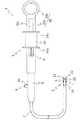
図1に示されるように、本発明の鉗子装置1は、体腔内組織を把持する開閉可能な鉗子片21、22を備えた把持部2と、把持部2の鉗子片21、22を開閉操作するためのスライド部31および把持部2を回転操作するための回転操作部32を備えた操作部3とを備えている。把持部2と操作部3との間には、操作部3からの操作力を把持部2に伝達するインナーケーブル4が設けられている。インナーケーブル4の周りには、図2および図3に示されるように、インナーケーブル4を囲繞するアウターケーシング5が設けられ、操作部3から把持部2までインナーケーブル4を案内している。また、操作部3の先端側には、操作部3の操作時に、医師等の施術者が握持するためのグリップ部6と、グリップ部6から把持部2側に向かって延び、内部にアウターケーシング5を回転可能に収容する管状の樹脂コート部7とを備えている。なお、本明細書において、「先端」という場合は、各部材のうち、鉗子装置1を操作する医師等の施術者から遠い側(すなわち、把持部2の自由端側)をいい、「基端」という場合は、各部材のうち、鉗子装置1を操作する医師等の施術者に近い側(すなわち、回転操作部32の自由端側)の方向をいう。 As shown in FIG. 1, the forceps device 1 of the present invention is configured to open and close the
本発明の鉗子装置1は、内視鏡(図示せず)に挿入されて体腔内に導入され、患部などの体腔内組織を、鉗子片21、22を遠隔操作することにより把持し、たとえば、高周波電流を鉗子片21、22に流して体腔内組織の焼灼止血などをする。詳細については後述するが、このような操作時において、把持部2の鉗子片21、22の向きが患部の向きに対して適切でない場合には、操作部3を回転操作すると把持部2が回転し、把持部2の向きを適切な向きに容易に調整することができ、患部の場所、向きに応じた処置を施すことができる。 The forceps device 1 of the present invention is inserted into an endoscope (not shown) and introduced into a body cavity, and grips tissue in the body cavity such as an affected part by remotely operating
図1および図3に示されるように、鉗子装置1の先端側に設けられた把持部2は、体腔内組織を把持する部位であり、一対の鉗子片21、22が、把持部ハウジング24に設けられた回転軸23を中心に回転可能に構成され、鉗子片21、22は操作部3の操作に応じて開閉する。図1および図3に示されるように、鉗子片21、22は、インナーケーブル4の引き操作がリンク機構Lにより開閉動作に変換され、開閉するように構成されている。このようなリンク機構Lとしては、公知のものを用いることができるので、用途や所望の作動動作に応じて適宜採用することできるために詳細には説明しない。なお、鉗子片21、22を開閉させるためには、リンク機構Lを用いる必要はなく、インナーケーブル4の操作力を鉗子片21、22の開閉動作に変換できる機構であれば、他の機構であっても構わない。また、図1および図3に示す実施形態では、1本のインナーケーブル4により鉗子片21、22が操作されるように構成されているが、2本のインナーケーブルにより鉗子片21、22が操作されるようにしてもよい。 As shown in FIGS. 1 and 3, the
把持部2を操作する操作部3は、図1に示されるように、医師等の施術者により回転操作される回転操作部32と、インナーケーブル4を操作するスライド部31とを備えている。回転操作部32は、施術者が把持部2を回転させるときに回転操作を加える部位である。図1に示す回転操作部32は、細長い略円筒状の回転操作部本体32aと、スライド部31をガイドするガイド部32cと、ガイド部32cよりも基端側に設けられ、回転操作をするために操作される回転部32bとを備えている。図1においては、ガイド部32cは、本体32aの軸方向に長さを有し、回転操作部本体32aに設けられた貫通したスリットとして示されている。回転部32bは、リング状部材として示されているが、その形状は限定されるものではない。スライド部31は、例えば内側に設けられた凸部がガイド部と摺動可能に嵌合するような態様が採用されるなど、回転操作部32に対して回転不能かつスライド自在に取り付けられる。スライド部31は、操作しやすいようにフランジ部31a、31bを有したボビン形状を有し、施術者の操作に伴ってガイド部32cの先端側、基端側の間を往復動作できるように構成されている。 As shown in FIG. 1, the
回転操作部32およびスライド部31の形状は、施術者が操作することができる形状であれば、図1に示す形状に限られることはなく、様々な形状とすることができる。また、回転操作をするために施術者が持つ部位(回転部32b)は、図1に示すリング状部材として示された回転部32bの位置であってもよいし、回転操作部本体32aの位置(すなわち、回転操作部本体32aを持って回転させる場合は、図1中、参照符号32aの位置が回転部となる)であってもよい。 As long as the shape of the
また、図1および図2に示されるように、本発明の鉗子装置1は、グリップ部6を有し、回転操作部32が、グリップ部6に対して回転可能に接続され、かつ、グリップ部6の基端側に設けられている。グリップ部6は、回転操作部32を施術者が操作するときに握持する部位である。グリップ部6は、インナーケーブル4およびアウターケーシング5を挿通するための挿通孔6aを有しており、挿通孔6a内で、インナーケーブル4を収容したアウターケーシング5が回転できるように構成されている。回転操作部32とグリップ部6との間の接続は、図2に示されるように、回転操作部32がグリップ部6に対して軸方向に移動しないように係合して接続されている。このような係合は、たとえば、回転操作部32の回転操作部本体32aに、円盤状の空洞32dを形成し、当該円盤状の空洞32dにグリップ部6の円盤状の突出部6bを係合させることにより、回転可能に接続することができる。なお、回転操作部32とグリップ部6との接続は、図2に示す構造に限られず、回転操作部32がグリップ部6に対して回転可能であれば、他の構造であっても構わない。 As shown in FIGS. 1 and 2, the forceps device 1 of the present invention has a
また、図1および図2に示す実施形態では、グリップ部6に高周波電源端子8が設けられている。高周波電源端子8は、グリップ部6に設けられた差込口6c内に設けられている。高周波電源端子8は、図1および図2においてはグリップ部6に設けられているが、後述するように、回転操作部32に設けてもよい。高周波電源端子8は、インナーケーブル4またはアウターケーシング5に接続され、インナーケーブル4またはアウターケーシング5が高周波電源端子8より把持部2へ高周波電流を通電可能な通電性を有することにより把持部2の鉗子片21、22に高周波電流を通電し、鉗子片21、22により把持した患部を焼灼することができる。なお、高周波電源端子8は、図示しない高周波電源にコードを介して接続される。インナーケーブル4またはアウターケーシング5が通電性を有するための構成は公知であるため、構造についての説明は省略する。 In the embodiment shown in FIGS. 1 and 2, the
高周波電流がインナーケーブル4またはアウターケーシング5に流れるため、図2に示されるように、グリップ部6の先端側には、絶縁性の樹脂コート部7が取り付けられ、患部以外の体腔内の組織に高周波電流が流れないようにされている。樹脂コート部7は可撓性を有し、体腔内をスムーズに移動できるように構成されている。 Since the high-frequency current flows through the
次に、インナーケーブル4およびアウターケーシング5の他の部材との接続関係について説明する。図2および図3に示されるように、インナーケーブル4は、基端側がスライド部31に回転不能に取り付けられ、先端側が把持部2に連結されている。したがって、スライド部31をスライドさせることによりインナーケーブル4が操作され、把持部2の鉗子片21、22が開閉される。具体的には、インナーケーブル4は、接着やそれ以外の公知の固着手段により、スライド部31に対して一体的に取り付けられ、スライド部31に対してインナーケーブル4が軸周りに回転しないように構成されている。これにより、回転操作部32がグリップ部6に対して回転し、それに伴いスライド部31が回転した場合であっても、スライド部31とインナーケーブル4との間で相対回転が生じない。したがって、回転操作時に、スライド部31とインナーケーブル4との間の接続部分において摩擦が生じず、インナーケーブル4の磨耗が生じることがない。インナーケーブル4の先端側は、図3に示されるように、リンク機構Lを介して鉗子片21、22と接続され、スライド部31が操作されることにより、鉗子片21、22が開閉操作される。 Next, the connection relationship between the
また、アウターケーシング5は、基端側が回転操作部32に対して回転不能に取り付けられ、先端側が樹脂コート部7に対して回転可能かつ軸方向移動不能に係合されている。また、アウターケーシング5内には、インナーケーブル4が摺動可能に収容されており、湾曲部分がある体腔内においても、インナーケーブル4の操作力を把持部2側に伝達することができる。アウターケーシング5は、接着やそれ以外の公知の固着手段により、回転操作部32に対して一体的に取り付けられ、回転操作部32に対してアウターケーシング5が軸周りに回転しないように構成されている。また、アウターケーシング5は、グリップ部6に対して固定されておらず、グリップ部6内で回転可能に構成されている。また、図3に示されるように、樹脂コート部7の先端側に設けられ、内周側に突出した係合部71と、アウターケーシング5の先端側に設けられた段部51により係合している。アウターケーシング5と樹脂コート部7との間の係合は、アウターケーシング5が樹脂コート部7内を回転することができ、アウターケーシング5が樹脂コート部7に対して軸方向に移動不能であれば、どのような構造であってもよい。また、アウターケーシング5の先端部は、図3に示されるように、把持部2の把持部ハウジング24に固定されている。把持部ハウジング24と樹脂コート部7とは互いに回転可能に構成される。 The
上述の構成により、回転操作部32を回転させることにより、インナーケーブル4およびアウターケーシング5が軸線回りに回転する。そして、インナーケーブル4およびアウターケーシング5が軸線回りに回転すると、把持部2が回転し、鉗子片21、22の体腔内での向きを調整することができる。回転操作部32の回転により、インナーケーブル4とアウターケーシング5とがともに回転するため、インナーケーブル4とアウターケーシング5との間で相対的な回転が生じない。したがって、インナーケーブル4とアウターケーシング5との間で生じる回転方向の摩擦抵抗が加わらず、インナーケーブル4とアウターケーシング5の回転とが同期するため、把持部2を正確に操作することができる。 With the above-described configuration, the
次に、図4〜図6に示した模式図を参照し、高周波電源端子8を設ける位置について説明する。図4は、高周波電源端子8が、回転操作部32側に設けられ、インナーケーブル4に高周波電源端子8が接続されている。図4に示す実施形態の場合は、スライド部31の操作により、インナーケーブル4が高周波電源端子8に対して軸方向に移動するため、たとえば滑り接触等の接触式の高周波電源端子8を用いることができる。図5は、高周波電源端子8が、回転操作部32側に設けられ、アウターケーシング5に高周波電源端子8が接続されている。図5に示す実施形態では、高周波電源端子8とアウターケーシング5との間で、軸方向、周方向での相対移動が生じないため、高周波電源端子8、アウターケーシング5に磨耗を生じることがない。図6は、高周波電源端子8が、グリップ部6を貫通してアウターケーシング5に接続されている。図6に示す実施形態の場合は、把持部2を回転させるために回転操作部32を回転しても、グリップ部6は回転しないため、高周波電源端子8が軸回りに回転することがない。したがって、高周波電源端子8と高周波電源とをつなぐコードが回転等により絡まることがないため、施術者が操作しやすい。また、高周波電源端子8の位置が、鉗子装置1を内視鏡に挿入した初期位置から変わることがない(回転方向の位置が変わらず、初期位置で上を向いていた高周波電源端子8が、コードをつなぐ段階で回転して、下を向いていたりすることがない)。したがって、施術者がコードをつなぐうえで、常に操作しやすい位置に高周波電源端子8を維持することができる。なお、アウターケーシング5は高周波電源端子8に対して相対的に回転するため、接触式の高周波電源端子8等、相対回転したときに導電性を維持する機構を用いることができる。 Next, the position where the high frequency
つぎに本発明の鉗子装置1の動作について説明する。 Next, the operation of the forceps device 1 of the present invention will be described.
まず、施術者は、スライド部31を操作して、把持部2の鉗子片21、22を閉じた状態とし、図示しない内視鏡に挿入し、体腔内の患部がある位置まで、把持部2を移動させる。 First, the practitioner operates the
患部の位置まで把持部2が移動すると、内視鏡で確認しながら、グリップ部6を握持して、回転操作部32を操作して、把持部2の向きを変える。グリップ部6は、患者の体に近い位置にあり、力が加わる回転操作部32は、グリップ部6よりも施術者側にある。ここで、回転操作部32とグリップ部6が本発明と逆の位置関係、すなわち、グリップ部6が基端側(施術者の手元側)にあり、回転操作部32が先端側(患者の体に近い側)にある場合、回転操作時に、施術者の手元側を軸として、先端側で回転操作部32の操作により揺動が生じ、その揺動が患者の体や、内視鏡に伝わってしまう。しかしながら、本発明の構造によれば、患者の体に近い側にあるグリップ部6がしっかりと握持され、回転操作部32に力が加わり、操作力が加わる回転操作部32の部分でグリップ部6を軸とした揺動が生じたとしても、その揺動は回転操作部32よりも患者の体に近い側で握持されたグリップ部6により抑えられる。したがって、患者の体や鉗子装置1が挿入される内視鏡に揺動が伝わらず、患者に負担がかかることがない。 When the
把持部2の回転は、たとえば、回転操作部32の回転部32bを回転させることにより行われる。回転操作部32が回転すると、回転操作部32に対して回転不能に取り付けられたスライド部31も回転する。回転操作部32とスライド部31が一体となって回転すると、回転操作部32に回転不能に取り付けられたアウターケーシング5と、スライド部31に回転不能に取り付けられたインナーケーブル4とが、回転操作部32、スライド部31と一体となってともに回転する。アウターケーシング5とインナーケーブル4とが回転すると、鉗子装置1の先端側において、アウターケーシング5とインナーケーブル4が連結された把持部2が回転する。この回転操作時において、インナーケーブル4は先端側、基端側ともに、スライド部31と把持部2に対して相対回転することなく固定されているため、相対回転することによる摩擦が生じないため、インナーケーブル4に磨耗が生じることがない。 The rotation of the
つぎに、患部を把持できるように、回転操作により把持部2を操作した後、スライド部31をスライドさせ、インナーケーブル4を操作し、把持部2の鉗子片21、22を開く。鉗子片21、22が開くと、鉗子片21、22の間に患部が来るように鉗子装置1全体を操作し、再度、スライド部31を逆方向にスライドさせ、鉗子片21、22を閉じて、患部を把持する。本発明の鉗子装置1では、上記回転操作から患部を把持するまで、施術者が手を持ちかえずに操作をすることができる。すなわち、グリップ部6をたとえば左手で握持して、右手で回転操作部32を回転することができ、スライド部31が回転操作部32に設けられ、片手で届く範囲に設けられているので、そのまま右手でスライド部31を操作することができる。また、回転操作時だけでなく、スライド操作時においても、グリップ部6が患者の体に近い側で握持されているので、スライド動作による揺動も防ぐことができる。したがって、鉗子装置1の操作が非常に容易であり、患者に負担がかかることがない。 Next, after operating the
患部が鉗子片21、22により把持されると、患部を焼灼するために、高周波電源端子8にコードを介して高周波電源を接続した後、高周波電流を鉗子片21、22に流して患部が焼灼される。このとき、グリップ部6に高周波電源端子8が設けられていることにより、把持部2の回転操作をした場合であっても、高周波電源端子8の位置が初期位置から変わることがない。したがって、施術者がコードを接続しやすい位置に高周波電源端子8を維持することができるため、施術者が操作しやすくなる。 When the affected part is grasped by the
上述のように、本発明の鉗子装置1は、鉗子装置1を医師等の施術者が操作するときに操作性が良く、鉗子装置1内に設けられたインナーケーブル4の接続部分に磨耗のおそれもなく、患者にも負担がかかることがない。 As described above, the forceps device 1 of the present invention has good operability when a practitioner such as a doctor operates the forceps device 1, and the connection portion of the
1 鉗子装置
2 把持部
21、22 鉗子片
23 回転軸
24 把持部ハウジング
3 操作部
31 スライド部
31a、31b フランジ部
32 回転操作部
32a 回転操作部本体
32b 回転部
32c ガイド部
32d 空洞
4 インナーケーブル
5 アウターケーシング
51 段部
6 グリップ部
6a 挿通孔
6b 突出部
6c 差込口
7 樹脂コート部
71 係合部
8 高周波電源端子
L リンク機構DESCRIPTION OF SYMBOLS 1
Claims (5)
Translated fromJapanese前記把持部の鉗子片を開閉操作するためのスライド部および前記把持部を回転操作するための回転操作部を備えた操作部と、
前記把持部と前記操作部との間に設けられ、前記操作部からの操作力を前記把持部に伝達するインナーケーブルと、
前記インナーケーブルを囲繞するアウターケーシングと、
前記操作部の操作時に握持するためのグリップ部と、
前記グリップ部から前記把持部側に向かって延び、内部に前記アウターケーシングを回転可能に収容する管状の樹脂コート部と
を備えた鉗子装置であって、
前記インナーケーブルは、基端側が前記スライド部に回転不能に取り付けられ、先端側が前記把持部に連結され、前記アウターケーシングは、基端側が前記回転操作部に対して回転不能に取り付けられ、先端側が前記樹脂コート部に対して回転可能かつ軸方向移動不能に係合され、
前記スライド部が前記回転操作部に対して回転不能かつスライド自在に取り付けられ、
前記スライド部をスライドさせることにより前記把持部の鉗子片を開閉し、
前記回転操作部を回転させることにより、前記インナーケーブルおよび前記アウターケーシングが軸線回りに回転して前記把持部が回転し、
前記回転操作部が、前記グリップ部に対して回転可能に接続され、かつ、前記グリップ部の基端側に設けられることを特徴とする鉗子装置。A grasping portion having an openable and closable forceps piece for grasping tissue in a body cavity;
An operation unit including a slide unit for opening and closing the forceps piece of the gripping unit and a rotation operation unit for rotating the gripping unit;
An inner cable that is provided between the grip portion and the operation portion and transmits an operation force from the operation portion to the grip portion;
An outer casing surrounding the inner cable;
A grip portion for gripping when operating the operation portion;
A forceps device including a tubular resin coat portion that extends from the grip portion toward the grip portion side and rotatably accommodates the outer casing,
The inner cable is attached non-rotatably on the base end side to the slide part, and the distal end side is connected to the grip part, and the outer casing is attached non-rotatably on the base end side with respect to the rotation operation part, Engageable with the resin coating portion so as to be rotatable and axially immovable,
The slide part is attached to the rotation operation part so as not to rotate and slide freely,
Opening and closing the forceps piece of the grip portion by sliding the slide portion,
By rotating the rotation operation unit, the inner cable and the outer casing rotate about an axis, and the gripping unit rotates,
The forceps device, wherein the rotation operation portion is rotatably connected to the grip portion and is provided on a proximal end side of the grip portion.
Priority Applications (4)
| Application Number | Priority Date | Filing Date | Title |
|---|---|---|---|
| JP2012226552AJP6110098B2 (en) | 2012-10-12 | 2012-10-12 | Forceps device |
| PCT/JP2013/077697WO2014058039A1 (en) | 2012-10-12 | 2013-10-11 | Forceps device |
| US14/430,747US20150230812A1 (en) | 2012-10-12 | 2013-10-11 | Forceps device |
| DE112013004978.3TDE112013004978T5 (en) | 2012-10-12 | 2013-10-11 | tweezers device |
Applications Claiming Priority (1)
| Application Number | Priority Date | Filing Date | Title |
|---|---|---|---|
| JP2012226552AJP6110098B2 (en) | 2012-10-12 | 2012-10-12 | Forceps device |
Publications (2)
| Publication Number | Publication Date |
|---|---|
| JP2014076227Atrue JP2014076227A (en) | 2014-05-01 |
| JP6110098B2 JP6110098B2 (en) | 2017-04-05 |
Family
ID=50477501
Family Applications (1)
| Application Number | Title | Priority Date | Filing Date |
|---|---|---|---|
| JP2012226552AActiveJP6110098B2 (en) | 2012-10-12 | 2012-10-12 | Forceps device |
Country Status (4)
| Country | Link |
|---|---|
| US (1) | US20150230812A1 (en) |
| JP (1) | JP6110098B2 (en) |
| DE (1) | DE112013004978T5 (en) |
| WO (1) | WO2014058039A1 (en) |
Cited By (1)
| Publication number | Priority date | Publication date | Assignee | Title |
|---|---|---|---|---|
| JP2024107537A (en)* | 2023-01-30 | 2024-08-09 | 矢崎総業株式会社 | Wire fixing device and wire harness |
Citations (6)
| Publication number | Priority date | Publication date | Assignee | Title |
|---|---|---|---|---|
| JPH09507149A (en)* | 1994-01-05 | 1997-07-22 | シンバイオシス・コーポレーション | Flexible microsurgical instrument with rotatable clevis |
| JP2008005965A (en)* | 2006-06-28 | 2008-01-17 | Olympus Medical Systems Corp | Endoscopic treatment tool |
| JP2009034388A (en)* | 2007-08-02 | 2009-02-19 | Olympus Medical Systems Corp | Operation unit structure of endoscope treatment tool |
| JP2009142622A (en)* | 2007-12-14 | 2009-07-02 | River Seiko:Kk | Operation part of high-frequency treatment instrument for endoscope |
| JP4659145B2 (en)* | 2009-03-18 | 2011-03-30 | オリンパスメディカルシステムズ株式会社 | Endoscopic treatment tool |
| JP2012016610A (en)* | 2011-09-21 | 2012-01-26 | Olympus Medical Systems Corp | High-frequency treatment device |
Family Cites Families (6)
| Publication number | Priority date | Publication date | Assignee | Title |
|---|---|---|---|---|
| US5810876A (en)* | 1995-10-03 | 1998-09-22 | Akos Biomedical, Inc. | Flexible forceps device |
| JP3634655B2 (en)* | 1999-02-09 | 2005-03-30 | ペンタックス株式会社 | Endoscopic biopsy forceps |
| US6527753B2 (en)* | 2000-02-29 | 2003-03-04 | Olympus Optical Co., Ltd. | Endoscopic treatment system |
| JP4880251B2 (en)* | 2005-06-21 | 2012-02-22 | オリンパスメディカルシステムズ株式会社 | High frequency treatment tool |
| JP4497379B2 (en)* | 2006-08-23 | 2010-07-07 | 朝日インテック株式会社 | Medical treatment tool |
| EP1955657B1 (en)* | 2007-02-08 | 2011-01-12 | Olympus Medical Systems Corp. | Treatment tool for endoscope |
- 2012
- 2012-10-12JPJP2012226552Apatent/JP6110098B2/enactiveActive
- 2013
- 2013-10-11USUS14/430,747patent/US20150230812A1/ennot_activeAbandoned
- 2013-10-11WOPCT/JP2013/077697patent/WO2014058039A1/enactiveApplication Filing
- 2013-10-11DEDE112013004978.3Tpatent/DE112013004978T5/ennot_activeWithdrawn
Patent Citations (6)
| Publication number | Priority date | Publication date | Assignee | Title |
|---|---|---|---|---|
| JPH09507149A (en)* | 1994-01-05 | 1997-07-22 | シンバイオシス・コーポレーション | Flexible microsurgical instrument with rotatable clevis |
| JP2008005965A (en)* | 2006-06-28 | 2008-01-17 | Olympus Medical Systems Corp | Endoscopic treatment tool |
| JP2009034388A (en)* | 2007-08-02 | 2009-02-19 | Olympus Medical Systems Corp | Operation unit structure of endoscope treatment tool |
| JP2009142622A (en)* | 2007-12-14 | 2009-07-02 | River Seiko:Kk | Operation part of high-frequency treatment instrument for endoscope |
| JP4659145B2 (en)* | 2009-03-18 | 2011-03-30 | オリンパスメディカルシステムズ株式会社 | Endoscopic treatment tool |
| JP2012016610A (en)* | 2011-09-21 | 2012-01-26 | Olympus Medical Systems Corp | High-frequency treatment device |
Cited By (2)
| Publication number | Priority date | Publication date | Assignee | Title |
|---|---|---|---|---|
| JP2024107537A (en)* | 2023-01-30 | 2024-08-09 | 矢崎総業株式会社 | Wire fixing device and wire harness |
| JP7719813B2 (en) | 2023-01-30 | 2025-08-06 | 矢崎総業株式会社 | Wire fixing device and wire harness |
Also Published As
| Publication number | Publication date |
|---|---|
| DE112013004978T5 (en) | 2015-07-16 |
| JP6110098B2 (en) | 2017-04-05 |
| WO2014058039A1 (en) | 2014-04-17 |
| US20150230812A1 (en) | 2015-08-20 |
Similar Documents
| Publication | Publication Date | Title |
|---|---|---|
| JP4056989B2 (en) | Endoscopic treatment tool | |
| JP4472362B2 (en) | Endoscopic treatment tool | |
| JP2009247888A (en) | Medical treatment system | |
| EP2022431B1 (en) | Operation section structure of treatment instrument for endoscopic use | |
| KR101847253B1 (en) | High frequency treatment tool | |
| JP6482101B2 (en) | Operation unit for bending treatment tools | |
| JP2012200518A (en) | Endoscopic treatment tool | |
| JP4481029B2 (en) | Endoscopic treatment tool | |
| JP6110098B2 (en) | Forceps device | |
| JP6284182B2 (en) | Operation unit for bending treatment tools | |
| JP5704858B2 (en) | Endoscopy forceps | |
| JP5134165B2 (en) | Treatment tool | |
| JP7113087B2 (en) | Endoscopic treatment tool | |
| CN110074830A (en) | Adjustable bending sheath tube regulation handle and adjustable bending sheath guard system | |
| JP5137758B2 (en) | Bipolar high-frequency treatment instrument for endoscope | |
| JP5191340B2 (en) | Endoscopic treatment tool | |
| WO2010071064A1 (en) | Treating device | |
| JP5653814B2 (en) | Endoscopic high-frequency treatment instrument | |
| JP5653814B6 (en) | Endoscopic high-frequency treatment instrument | |
| JP2004194849A (en) | Endoscope grasping forceps |
Legal Events
| Date | Code | Title | Description |
|---|---|---|---|
| A621 | Written request for application examination | Free format text:JAPANESE INTERMEDIATE CODE: A621 Effective date:20150904 | |
| RD02 | Notification of acceptance of power of attorney | Free format text:JAPANESE INTERMEDIATE CODE: A7422 Effective date:20150904 | |
| A131 | Notification of reasons for refusal | Free format text:JAPANESE INTERMEDIATE CODE: A131 Effective date:20160809 | |
| A521 | Request for written amendment filed | Free format text:JAPANESE INTERMEDIATE CODE: A523 Effective date:20161011 | |
| TRDD | Decision of grant or rejection written | ||
| A01 | Written decision to grant a patent or to grant a registration (utility model) | Free format text:JAPANESE INTERMEDIATE CODE: A01 Effective date:20170214 | |
| A61 | First payment of annual fees (during grant procedure) | Free format text:JAPANESE INTERMEDIATE CODE: A61 Effective date:20170309 | |
| R150 | Certificate of patent or registration of utility model | Ref document number:6110098 Country of ref document:JP Free format text:JAPANESE INTERMEDIATE CODE: R150 | |
| R250 | Receipt of annual fees | Free format text:JAPANESE INTERMEDIATE CODE: R250 | |
| R250 | Receipt of annual fees | Free format text:JAPANESE INTERMEDIATE CODE: R250 | |
| R250 | Receipt of annual fees | Free format text:JAPANESE INTERMEDIATE CODE: R250 | |
| R250 | Receipt of annual fees | Free format text:JAPANESE INTERMEDIATE CODE: R250 | |
| R250 | Receipt of annual fees | Free format text:JAPANESE INTERMEDIATE CODE: R250 | |
| R250 | Receipt of annual fees | Free format text:JAPANESE INTERMEDIATE CODE: R250 |