JP2014073641A - Double clip - Google Patents
Double clipDownload PDFInfo
- Publication number
- JP2014073641A JP2014073641AJP2012222608AJP2012222608AJP2014073641AJP 2014073641 AJP2014073641 AJP 2014073641AJP 2012222608 AJP2012222608 AJP 2012222608AJP 2012222608 AJP2012222608 AJP 2012222608AJP 2014073641 AJP2014073641 AJP 2014073641A
- Authority
- JP
- Japan
- Prior art keywords
- pressing plate
- clip
- double clip
- tip
- plate
- Prior art date
- Legal status (The legal status is an assumption and is not a legal conclusion. Google has not performed a legal analysis and makes no representation as to the accuracy of the status listed.)
- Granted
Links
- 238000005452bendingMethods0.000claimsabstractdescription13
- 239000002184metalSubstances0.000claimsabstractdescription12
- 238000003825pressingMethods0.000claimsdescription136
- 238000003780insertionMethods0.000claimsdescription34
- 230000037431insertionEffects0.000claimsdescription34
- 238000005520cutting processMethods0.000claimsdescription3
- 238000003860storageMethods0.000description9
- 238000013459approachMethods0.000description6
- 239000007799corkSubstances0.000description6
- 239000000463materialSubstances0.000description6
- 230000002093peripheral effectEffects0.000description6
- 238000004519manufacturing processMethods0.000description4
- 238000000465mouldingMethods0.000description4
- 229920005989resinPolymers0.000description4
- 239000011347resinSubstances0.000description4
- 229920003002synthetic resinPolymers0.000description4
- 239000000057synthetic resinSubstances0.000description4
- 238000004804windingMethods0.000description3
- 229910000831SteelInorganic materials0.000description2
- 239000012141concentrateSubstances0.000description2
- 238000010586diagramMethods0.000description2
- 229920001971elastomerPolymers0.000description2
- 239000000806elastomerSubstances0.000description2
- 230000005484gravityEffects0.000description2
- 230000003014reinforcing effectEffects0.000description2
- 239000010959steelSubstances0.000description2
Images


Landscapes
- Sheet Holders (AREA)
Abstract
Description
Translated fromJapanese本発明は、紙葉類を束ねて挟持するためのダブルクリップに関する。 The present invention relates to a double clip for bundling and pinching paper sheets.
紙葉類を束ねるための挟持具としては、弾性力を有する金属板を断面視略二等辺三角形状に折り曲げてクリップ本体を形成し、開閉レバーを起伏自在に取り付けたダブルクリップがよく知られている。このダブルクリップは構造が簡単で使いやすい反面、挟持部の先端縁部に挟持力が集中するために挟持された紙葉類に筋状の痕跡が残るという不都合があり、さらにクリップ本体が金属製であるために滑りやすく、紙葉が少ない場合の保持力に問題があった。 As a holding tool for bundling paper sheets, a double clip in which a metal plate having elasticity is bent into an approximately isosceles triangle shape in cross-sectional view to form a clip body, and an open / close lever is attached in a undulating manner is well known. Yes. This double clip has a simple structure and is easy to use, but it has the inconvenience that streaks remain on the pinched paper sheets because the pinching force concentrates on the leading edge of the pinching part, and the clip body is made of metal. Therefore, there is a problem in the holding force when the paper is slippery and there are few paper sheets.
そこで、この不都合を解消するものとして例えば特許文献1に開示されている提案がある。この提案は、挟持部の先端縁部内側にコルク板を貼り付けることによって紙葉に対する摩擦係数を大きくするとともに弾性力をも付与し、不用意に外れたり挟持痕を残したりすることがないようにしたものである。 Therefore, there is a proposal disclosed in Patent Document 1, for example, as a means for solving this inconvenience. This proposal increases the coefficient of friction against the paper sheet by attaching a cork board to the inside of the front edge of the clamping part, and also gives an elastic force so that it does not accidentally come off or leave a clamping trace. It is a thing.
しかしながら、前記の提案にかかるダブルクリップは、湾曲した挟持部の先端縁部内側にコルク板を巻き付けて貼着することが難しいうえ、使用しているうちにコルク板が擦れることによって摩耗したり剥がれたりしてしまうおそれがある、といった幾多の欠点を有しており、実際的ではなかった。 However, the double clip according to the above-mentioned proposal is difficult to be attached by winding a cork plate around the inner edge of the tip of the curved clamping part, and wears or peels off due to rubbing of the cork plate during use. It has a number of drawbacks, such as the risk of being lost.
本発明は、かかる従来のダブルクリップの問題点を鑑みてなされたもので、その目的は、紙葉の枚数が少ない場合でもしっかりと保持でき、しかも挟持痕の残らないダブルクリップを簡単な構造で安価に提供することにある。 The present invention has been made in view of the problems of such a conventional double clip, and its purpose is to hold a double clip with a simple structure that can be firmly held even when the number of paper sheets is small and that does not leave a pinch mark. It is to provide at low cost.
かかる目的を達成するために本発明のダブルクリップは、
弾性力を有する薄板を断面視略二等辺三角形状に折り曲げることによって背板と該背板の長さ方向両端縁からそれぞれ延設される一対の対向する挟持板とが形成され、該挟持板のそれぞれに軸受け部と先端縁挟持部とが設けられたクリップ本体と、金属線を略U字形状に折り曲げ、さらにその両先端部を幅方向外向きに折り曲げることによって摘み部とアーム部と回動軸部とが形成された開閉レバーと、からなり、前記クリップ本体側の軸受け部に開閉レバー側の回動軸部が起伏自在に差し込まれたダブルクリップにおいて、
前記一対の挟持板の先端縁挟持部に押圧板が回動自在にそれぞれ取り付けられ、該押圧板を介して紙葉類が挟持されることを特徴とするものである。In order to achieve such an object, the double clip of the present invention
A thin plate having elastic force is bent into a substantially isosceles triangle shape in cross-section to form a back plate and a pair of opposing holding plates respectively extending from both longitudinal edges of the back plate. A clip body with a bearing portion and a tip edge clamping portion on each of them, and a knob and an arm portion can be rotated by bending a metal wire into a substantially U shape and then bending both tip portions outward in the width direction. An open / close lever formed with a shaft portion, and a double clip in which a pivot shaft portion on the open / close lever side is inserted in a undulating manner into a bearing portion on the clip body side,
The pressing plates are rotatably attached to the leading edge holding portions of the pair of holding plates, respectively, and the paper sheets are held via the pressing plates.
このような構成をとることによって、先端縁挟持部に加わる挟持力は押圧板の面全体に分散されて紙葉類に伝わるようになり、紙葉類に挟持痕が残ることがなくなる。また、先端縁挟持部も押圧板の厚み分だけ外方向(先端縁挟持部同士が離れる方向)に押し広げられるため、その広がり分だけ弾性復元力すなわち挟持力も強くなり、紙葉が少なくともしっかりと保持することが可能となる。 By adopting such a configuration, the clamping force applied to the leading edge clamping unit is distributed over the entire surface of the pressing plate and is transmitted to the paper sheet, so that no clamping trace remains on the paper sheet. Further, since the leading edge holding part is also expanded outward by the thickness of the pressing plate (the direction in which the leading edge holding parts are separated from each other), the elastic restoring force, that is, the holding force is increased by the extension, and the paper sheet is at least firmly It becomes possible to hold.
なお、前記先端縁挟持部が前記軸受け部を兼ねるとともに、該先端縁挟持部の幅方向外側にそれぞれ挿通口を設け、前記開閉レバーの回動軸部を先端縁挟持部に差し込んだ状態にしたときに回動軸部の先端部がこの挿通口から突出するように回動軸部の長さを設定し、前記押圧板には前記回動軸部の先端部がそれぞれ回動可能に嵌合する支持孔を穿設した一対の支持壁を設け、
開閉レバーの回動軸部を先端縁挟持部に差し込んでそのそれぞれの先端部を前記押圧板の支持孔に回動自在に嵌合させることによって押圧板を取り付けるものであってもよい。The front end edge holding portion also serves as the bearing portion, and an insertion port is provided on each outer side in the width direction of the front end edge holding portion so that the rotation shaft portion of the opening / closing lever is inserted into the front end edge holding portion. Sometimes the length of the rotating shaft is set so that the tip of the rotating shaft protrudes from the insertion opening, and the tip of the rotating shaft is fitted to the pressing plate so as to be rotatable. Providing a pair of support walls with perforated support holes;
You may attach a press plate by inserting the rotation shaft part of an opening-and-closing lever in a front-end | tip edge clamping part, and fitting each front-end | tip part to the support hole of the said press plate so that rotation is possible.
このような構成をとることによって、従来のダブルクリップから大きな変更を加えることなく、しかも簡単に押圧板を取り付けることができる。 By adopting such a configuration, the pressing plate can be easily attached without greatly changing from the conventional double clip.
また、前記挟持板の、先端縁挟持部周りの適宜位置を切り欠いて取り付け窓部を形成するとともに、前記押圧板の該取り付け窓部に対応する位置に抱持部を立設し、取り付け窓部を通した該抱持部によって先端縁挟持部を回動可能に抱持することで押圧板を取り付けるものであってもよい。 In addition, an attachment window portion is formed by cutting out an appropriate position around the tip edge clamping portion of the clamping plate, and a holding portion is erected at a position corresponding to the attachment window portion of the pressing plate. The pressing plate may be attached by holding the leading edge holding part rotatably by the holding part that passes through the part.
このような構成をとることによって、簡単かつ確実に押圧板の取り付けが可能であるという利点が生じる。 By taking such a configuration, there is an advantage that the pressing plate can be easily and reliably attached.
また、前記先端縁挟持部の幅方向外側にそれぞれ挿通口を設けるとともに、前記押圧板に、該挿通口に対応する支持軸を有する一対の支持壁を立設し、該支持軸を前記挿通口に回動可能に嵌合させることによって押圧板を取り付けるものであってもよい。 In addition, an insertion port is provided on each outer side in the width direction of the tip edge sandwiching portion, and a pair of support walls having a support shaft corresponding to the insertion port is provided upright on the pressing plate, and the support shaft is connected to the insertion port. It is also possible to attach the pressing plate by fitting it in a pivotable manner.
このような構成をとることによって、クリップ本体や開閉レバーを変更することなく押圧板の取り付けが可能であるという利点が生じる。 By taking such a configuration, there is an advantage that the pressing plate can be attached without changing the clip body or the opening / closing lever.
また、前記押圧板の一対のうち一方に筆記具を着脱自在に挟持することができるクリップ部を設けても良い。 Moreover, you may provide the clip part which can clamp a writing instrument in one of the pair of the said press plates so that attachment or detachment is possible.
このような構成をとることによって、メモ用紙などを挟持した際に、それに書き込むための筆記具をも付帯させることができ、いちいち筆記具を探す手間がなくなるという利点が生じる。 By adopting such a configuration, when a memo sheet or the like is sandwiched, a writing tool for writing on the memo paper or the like can be attached, and there is an advantage that there is no need to search for the writing tool.
また、前記押圧板の一対のうち一方の前端縁が他方の押圧板の前端縁よりも前方向に延設されたものであってもよい。 Moreover, one front end edge of the pair of the pressing plates may extend in the front direction from the front end edge of the other pressing plate.
このような構成をとることによって、紙葉類をクリップ本体内に差し込む際のガイドとしての役割を押圧板に付け加えることができ、より簡単に紙葉類を差し込むことができるという利点が生じる。なお、ここでいう前方向とはクリップ本体を基準として背板側を後方向、先端縁挟持部側を前方向としてのことである。 By taking such a configuration, a role as a guide when inserting the paper sheet into the clip body can be added to the pressing plate, and there is an advantage that the paper sheet can be inserted more easily. The forward direction here refers to the back plate side as the rear direction and the tip edge clamping portion side as the forward direction with respect to the clip body.
本発明によれば、紙葉類をしっかりと挟持することができ、しかも挟持痕の残らないダブルクリップを簡単な構造で安価に提供することができる。 ADVANTAGE OF THE INVENTION According to this invention, paper sheets can be clamped firmly and the double clip which does not leave a pinch trace can be provided with a simple structure at low cost.
以下、本発明にかかるダブルクリップの実施形態を図に基づき説明するが、これに限定されるものではない。 Hereinafter, although the embodiment of the double clip concerning the present invention is described based on a figure, it is not limited to this.
≪第1実施形態≫
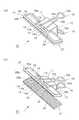
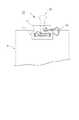
図1ないし図2は本発明にかかるダブルクリップの第1実施形態を示しており、図1の(a)は挟持部を閉じた状態の斜視図、(b)は開いた状態の斜視図。図2の(a)は分解斜視図、(b)は平面図である。<< First Embodiment >>
1 and 2 show a first embodiment of a double clip according to the present invention, in which (a) in FIG. 1 is a perspective view in a state where a clamping portion is closed, and (b) is a perspective view in an opened state. 2A is an exploded perspective view, and FIG. 2B is a plan view.
図において、ダブルクリップ10は、クリップ本体11と、それぞれ一対の開閉レバー16・16および押圧板17・17と、で構成されている。 In the figure, the
このうちクリップ本体11は、金属や合成樹脂等の弾性復元力に優れる薄板材からなっており、これを折り曲げることによって、背板12と、これの長さ方向両端縁からそれぞれ延設される一対の挟持板13・13とで構成される断面視略二等辺三角形形状に形成されている。挟持板13・13の先端縁の幅方向両側はそれぞれさらに前方向(背板が配された側とは反対の方向)に延出したのち外側(お互いが離れる方向)に向かって筒状に丸められ、先端縁挟持部14・14を形成している。この先端縁挟持部14・14は開閉レバー16が起伏自在にクリップ本体11に取り付けられるための軸受け部としての役割をも担っており、幅方向内側にはこの開閉レバー16の先端部を挿入するための差し込み口14aを、幅方向外側にはこれを突き出すための挿通口14bをそれぞれ有している。また、挟持板13の先端縁の中央部も同様に延設されたのち外側(先端部が離れる方向)に向かって略U字形状に丸められ、開閉レバー16の先端を先端縁挟持部14内に導くための案内部15を形成している。 Of these, the clip
かかるクリップ本体11の構成は、従来ダブルクリップのそれと何ら変わるものではない。 The structure of the
つぎに開閉レバー16は、剛性の高い金属線材を折り曲げてなるもので、幅方向に円弧状に膨出する摘み部16a、該摘み部の両端部からそれぞれ延出し先端にいくにつれて幅方向に緩やかに拡開するアーム部16b・16b、さらに該アーム部の先端から幅方向外向きに延出する回動軸部16c・16c、とで構成されている。 Next, the open /
かかる開閉レバー16の構成も前記のクリップ本体11と同様に従来ダブルクリップに備えられているそれと何ら変わるものではないが、回動軸部16c・16cの長さのみが従来よりも長く設定されており、軸受け部を兼ねた先端縁挟持部14の差し込み口14aに差し込んだ状態にあるときにその先端部が該差し込み口14aの反対側に位置する挿通口14bから突出するようになっている。 The configuration of the opening / closing
つぎに押圧板17は、合成樹脂よりなるもので、平面視で幅方向に長い矩形平板状に形成された押圧板本体18と、該押圧板本体18の一面側の両端に対向して立設された支持壁19・19とで構成されている。支持壁19・19はクリップ本体11側の先端縁挟持部14にある挿通口14bに当接する位置に配されており、さらに、この支持壁19・19のお互いが対向する側の壁面にはそれぞれ回動軸部16c・16cの先端部を差し入れるための支持孔19a・19aがそれぞれ穿設されている。 Next, the
かかる構成を有する本実施形態のダブルクリップ10は、クリップ本体11に、つぎのようにして押圧板17を取り付ける。 In the
すなわち、本実施形態においても従来ダブルクリップと同様に、まず開閉レバー16のアーム部16b・16bを幅方向内向き(お互いが近づく方向)に縮めておき、先端縁挟持部14・14の間に設けられている湾曲した案内部15の内側に回動軸部16cを配してから縮めていた力を開放すれば開閉レバー16自身の弾性復元力によってアーム部16bは元の状態に戻り、つれて回動軸部16cは先端縁挟持部14内に差し込み口14aから差し込まれる訳であるが、このとき本実施形態では、さらに押圧板17側の支持壁19に穿設されている支持孔19aを先端縁挟持部14の外側にある挿通口14b・14bの位置に合わせておくことで該挿通口14b・14bから突出してくる回動軸部16c・16cのそれぞれの先端部がそのまま支持孔19a・19aと嵌合して押圧板17が取り付けられることになる。 That is, also in this embodiment, like the conventional double clip, first, the
ちなみに、作業工程は増えるが、先に開閉レバー16を取り付けておき、その後に該開閉レバー16が軸受け部から外れない程度に再びアーム部16b・16bを押し縮めてから押圧板17を取り付けるようにするようにしてもよい。 Incidentally, although the number of work steps is increased, the opening / closing
本実施形態のダブルクリップ10では、このように押圧板17を簡単に取り付けることができる。さらに、従来ダブルクリップからの変更点は押圧板17の追加と開閉レバー16に形成された回動軸部16cの長さのみであるため、従来ダブルクリップを製造するための設備をほとんど変更することなく使用することができるという利点を有する。 In the
つぎに、このダブルクリップ10を使用するには、従来ダブルクリップと同様に開閉レバー16・16の摘み部16a・16aを摘んでクリップ本体11の先端縁挟持部14・14がお互い離れる方向に押し拡げ、そこに紙葉類を差し込んでから摘み部16a・16aに加えていた力を緩めてやればよい。そうすると先端縁挟持部14・14のそれぞれには押圧板17・17が取り付けられているために紙葉類は該押圧板17・17を介して挟み込まれることになり、押圧板17は回動自在に先端縁挟持部14に取り付けられているので紙葉類がいかなる厚みであっても追随して面全体が密接し、挟持力はこの面全体を通して分散されて紙葉類に伝わることになるため、確実に挟持することができ、かつ取り外し後も紙葉類に痕跡が残ることがない。 Next, in order to use this
また、本願発明のダブルクリップではクリップ本体の先端縁挟持部が直接紙葉類を挟むのではなく、押圧板を介する。したがって、その厚み分だけ挟持板は開方向に押し広げられることになり、少ない枚数を挟持する際にも従来のダブルクリップよりも挟持力が強くなるという利点も有することになる。 Further, in the double clip of the present invention, the leading edge holding part of the clip body does not directly hold the paper sheets but via a pressing plate. Therefore, the sandwiching plate is expanded in the opening direction by the thickness, and there is an advantage that the sandwiching force is stronger than the conventional double clip even when a small number of sheets are sandwiched.
さらに、従来ダブルクリップでは先端縁挟持部間に僅かな間隙が生じても紙葉類が挟めなくなるため、その精度には非常に厳密なものが要求されたが、本願発明のダブルクリップでは例えば押圧板の厚み分だけの間隙があったとしても充分挟持可能であり、それほど厳密な精度を必要としない。したがって製造が容易であるという利点も有する。 Furthermore, in the conventional double clip, paper sheets cannot be pinched even if a slight gap is generated between the leading edge holding parts. Therefore, a very strict accuracy is required. Even if there is a gap corresponding to the thickness of the plate, it can be sufficiently clamped and does not require so much precision. Therefore, it has the advantage that manufacture is easy.
以上、説明したように、本発明のダブルクリップは、挟持力が強く、重ねた紙葉類が少なくともしっかりと挟持することができるうえに痕跡もつきにくく、しかも製造も容易におこなうことができるという利点をもっている。 As described above, the double clip of the present invention has a strong clamping force, and can hold the stacked paper sheets at least firmly, hardly cause a trace, and can be easily manufactured. Has advantages.
≪第2実施形態≫
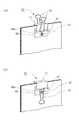
図3は本願発明にかかる収納ケースの第2実施形態を示しており、(a)は挟持部を閉じた状態、(b)は開いた状態の斜視図である。<< Second Embodiment >>
FIGS. 3A and 3B show a second embodiment of the storage case according to the present invention, in which FIG. 3A is a perspective view showing a state in which the clamping portion is closed, and FIG.
図において、符号20はダブルクリップ、27は本実施形態における押圧板を示している。なお、この第2実施形態の基本的な構成は第1実施形態とほぼ同じである。よって、煩雑さを避けるために同一箇所には同一符号を付して説明を省略し、異なる箇所のみ説明をおこなう。これは以降の実施形態も同様とする。 In the figure,
ここでの押圧板27は押圧板本体28が第1実施形態のものよりも幅方向に長く形成されており、その周縁部に沿っては補強用の枠部28aが立設されているものとなっている。 Here, the
このような構成にすることによって、クリップ本体11を小型化しても広い幅を挟持することが可能となり、嵩張らないうえに開動作が容易となるという利点が生じる。 By adopting such a configuration, even if the
さらに、ここでは押圧板27は二色成型によって形成されており、厚み方向略中央部から下半分すなわち紙葉類に当接する当接部28b(図に示す網掛け部分)は、その材質に摩擦係数の大きい樹脂材料、例えばエラストマー樹脂等が用いられている。こうすることによって少ない枚数を挟持する場合であっても滑りにくく、さらにしっかりと保持することができるという利点が生じる。なお、当接部28bは二色成型で形成されたものに限るものではなく、例えば別体として形成し、これを押圧板本体28に重ね合わせて組み付けたものであってもよい。 Further, here, the
≪第3実施形態≫
図4は本願発明にかかるダブルクリップの第3実施形態を示しており(a)は挟持部を開いた状態の斜視図、(b)は使用状態の斜視図である。«Third embodiment»
4A and 4B show a third embodiment of a double clip according to the present invention, in which FIG. 4A is a perspective view in a state where a clamping portion is opened, and FIG. 4B is a perspective view in a use state.
図において、符号30はダブルクリップ、37は本実施形態における押圧板、Sは紙葉類、をそれぞれ示している。なお、使用状態を示す図の場合、煩雑さを避けるために要部のみに符号を付している。これは以下の実施形態においても同様である。 In the figure,
ここでの押圧板37は、押圧板本体38が平面視で略直角三角形に形成されており、主として紙葉類Sの角部を留めることを目的としている。 Here, the
このように本発明にかかるダブルクリップは、押圧板本体の形状を変えるだけで様々な用途に適したクリップを容易に提供することができるという利点がある。なお、押圧板本体の形状が矩形である場合は前後方向略中央部に先端縁挟持部を配するだけで均等に挟持力が押圧板本体に伝わるが、本実施形態のように前後で面積の異なるような複雑な形状の場合は、押圧板本体の重心位置に先端縁挟持部を配するようにすることで挟持力を均等に押圧板本体に伝えることができる。 Thus, the double clip concerning this invention has the advantage that the clip suitable for various uses can be provided easily only by changing the shape of a press plate main body. In addition, when the shape of the pressing plate body is rectangular, the clamping force is evenly transmitted to the pressing plate body simply by disposing the tip edge clamping portion at the substantially central portion in the front-rear direction. In the case of different complicated shapes, the clamping force can be evenly transmitted to the pressing plate body by arranging the tip edge clamping portion at the center of gravity of the pressing plate body.
≪第4実施形態≫
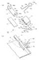
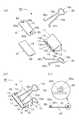
図5および図6は本願発明にかかるダブルクリップの第4実施形態を示しており、図5(a)は挟持部を閉じた状態の斜視図、(b)は開いた状態の側面図。図6(a)、(b)はそれぞれ使用状態の斜視図である。<< Fourth Embodiment >>
5 and 6 show a fourth embodiment of the double clip according to the present invention, in which FIG. 5 (a) is a perspective view in a state where a clamping portion is closed, and FIG. 5 (b) is a side view in an opened state. FIGS. 6A and 6B are perspective views of the usage state.
図において、符号40はダブルクリップ、47は下側に配された押圧板、48は該押圧板47の押圧板本体、をそれぞれ示している。 In the figure,
ここでの押圧板47は、押圧板本体48の前端縁が、上側に配された押圧板17の前端縁よりも前方向に延出して形成されており、紙葉類Sを挟んでクリップ本体11内に導くための案内板としての役割をも果すことができるようになっている。このような構成とすることで紙葉類Sが多く重ねられて厚みがある場合でも、一旦、この押圧板本体48の前端部に紙葉類Sの端部を載せ、滑らすように挟持板13・13内に押しこむことで容易に挟み込み作業をおこなうことができるという利点が生じる。 Here, the
さらに、この本第4実施形態では、押圧板本体48の裏面に円環状の支持壁48aが垂設されており、これの内周部に円盤状の磁石Mが取り付けられている。こうした構成をとることで、スチール製の壁面や机の側部にこのダブルクリップ40を吸着させて紙葉類Sを吊り下げることができるようになり、保管場所をとらないという利点が生じる。 Further, in the fourth embodiment, an
なお、磁石Mを取り付ける位置は図6(a)、(b)に示すように開閉レバー16が起伏どちらの状態にあってもこれと干渉しないような位置にあることが望ましいが、これは中央部に限らず、例えば幅方向両側の二箇所に振り分けて配設したものであってもよい。
≪第5実施形態≫
図7は本願発明にかかるダブルクリップの第5実施形態を示しており、図5(a)は分解斜視図、(b)は筆記具を取り付けた使用状態の斜視図である。6A and 6B, it is desirable that the magnet M be attached at a position where it does not interfere with the open /
«Fifth embodiment»
FIG. 7 shows a fifth embodiment of a double clip according to the present invention, in which FIG. 5 (a) is an exploded perspective view, and FIG. 7 (b) is a perspective view of a use state with a writing instrument attached.
図において、符号50はダブルクリップ、57は上側に配される押圧板、58は該押圧板57の押圧板本体、Hは筆記具、をそれぞれ示している。 In the figure,
ここでの押圧板57は、押圧板本体58の幅方向両端縁から一対のクリップ部58a・58aがそれぞれ立設されており、ここに筆記具Hを着脱自在に装着することができるようになっている。具体的には、この一対のクリップ部58a・58aは、薄板状のもので、その上部が切り欠かれることによって筆記具Hの胴部が収納可能な収納部58b・58bが形成されている。この収納部58b・58bの周壁はアーチ状に内側(お互いが近づく方向)に向かって湾曲して形成され、一旦収納された筆記具Hが不用意に脱落することを防ぐようになっている。 Here, the
このような構成とすることによって、不要な紙葉類Sを裏向きに束ねてメモ帳代わりに使用する場合等に筆記具Hをいちいち探す必要がなくなり、利便性が向上するという利点がある。 With such a configuration, there is no need to search for the writing implement H every time when unnecessary paper sheets S are bundled face down and used instead of a notepad, and there is an advantage that convenience is improved.
なお、ここではクリップ部58aは押圧板本体58の幅方向両端部にそれぞれ形成されたものとしたが、例えば押圧板本体58の前端縁中央部のみが上側に大きく湾曲して筆記具Hを挟持するような形態であってもよく、要は筆記具を着脱自在にしっかりと装着できるものであればよい。
≪第6実施形態≫
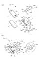
図8は本願発明にかかるダブルクリップの第6実施形態を示しており、(a)は分解斜視図、(b)は閉じた状態の斜視図である。Here, the
<< Sixth Embodiment >>
8A and 8B show a sixth embodiment of the double clip according to the present invention, in which FIG. 8A is an exploded perspective view and FIG. 8B is a perspective view in a closed state.
図において、符号60はダブルクリップ、61はクリップ本体、66は開閉レバー、67は押圧板を示している。 In the figure,
ここでの開閉レバー66は従来ダブルクリップと同じ形状をとっている。すなわち回動軸部66cは、その先端部がクリップ本体側の先端縁挟持部の突出口から突出しない程度の長さに設定されている。 The opening / closing
そして、その代わりに本実施形態では押圧板67を取り付ける手段として、クリップ本体61に形成されている挟持板13のうち先端縁挟持部14・14周りの幅方向略中央部がそれぞれ切り欠かれることによって取り付け窓部63a・63aが形成されるとともに、押圧板67の、該取り付け窓部63a・63aに対応する位置に、抱持部69・69が立設されている。この抱持部69は、具体的にはそれぞれが近づく方向に湾曲する一対のアームによって構成されており、先端縁挟持部14を回動自在に抱持可能となっている。そして、前記アームの一方をクリップ本体61側に設けられた取り付け窓部63aに差し込むようにしながら先端縁挟持部14をアームとアームの間に押し込むとアームが弾性変形して該先端縁挟持部14を受け入れ、収納後に復元して前記先端縁挟持部14を回動自在に抱持した状態となり、押圧板67が取り付けられる。 Instead of this, in the present embodiment, as a means for attaching the
このように、押圧板は、開閉レバーの回動軸部を介してクリップ本体の先端縁挟持部に取り付けるものに限るものではなく、先端縁挟持部に直接取り付けるものであってもよい。
≪第7実施形態≫
図9および図10は本願発明にかかるダブルクリップの第7実施形態を示しており、図9(a)は分解斜視図、(b)は閉じた状態の斜視図、図10は使用時に開閉レバーを倒した状態の平面図である。As described above, the pressing plate is not limited to the one attached to the tip edge holding portion of the clip body via the rotation shaft portion of the opening / closing lever, and may be directly attached to the tip edge holding portion.
<< Seventh Embodiment >>
9 and 10 show a seventh embodiment of the double clip according to the present invention. FIG. 9 (a) is an exploded perspective view, FIG. 10 (b) is a perspective view in a closed state, and FIG. It is a top view of the state which fell down.
図において、符号70はダブルクリップ、71はクリップ本体、76は開閉レバー、77は押圧板、をそれぞれ示している。 In the figure,
ここではクリップ本体71に開閉レバー76の回動軸部76cを取り付けるための軸受け部99は、先端縁挟持部14とは別に設けられている。 Here, the bearing
詳しくは、この軸受け部99は、クリップ本体71の挟持板13の略中央付近に先端縁挟持部14に対し45°の角度をもつ仮想線を配しこれの両端部に相当する位置を略コ字形状に切り欠き、該切り欠き片を外向きにそれぞれ筒状に巻き上げて形成されている。そして、開閉レバー76側の回動軸部76c・76cも、これに対応する角度をもって幅方向外向きに屈曲してアーム部76b・76bから延出されており、折り畳まれて伏臥状態にあるときには図10に示すように先端縁挟持部14と平行する方向に前記アーム部76b・76bが伸びることによって紙葉類S側への張り出しが生じないようになっている。 Specifically, the bearing
かかる構成は既知のものであるが、本発明はこのような形態、すなわち先端縁挟持部と軸受け部とが別々に設けられたダブルクリップにも適用することができる。 Such a configuration is known, but the present invention can also be applied to such a form, that is, a double clip in which the tip edge holding portion and the bearing portion are separately provided.
また、ここでは取り付け窓部73aは挟持板13の先端縁挟持部14の幅方向略中央周りではなく、幅方向外側周りすなわち挟持部外側縁部を切り欠くことによって形成されたものとなっており、押圧板77に形成された抱持部79・79もこれに対応したものとなっている。 Further, here, the
このように取り付け窓部の位置は限定されるものではなく、要は押圧板を回動自在に先端縁挟持部に取り付けられる位置であればどこであってもよい。
≪第8実施形態≫
図11は本願発明にかかるダブルクリップの第8実施形態を示しており、(a)は分解斜視図、(b)は閉じた状態の斜視図、(c)は押圧板の正面図である。Thus, the position of the attachment window portion is not limited, and may be any position as long as it is a position where the pressing plate can be rotatably attached to the tip edge holding portion.
<< Eighth Embodiment >>
FIG. 11 shows an eighth embodiment of a double clip according to the present invention, in which (a) is an exploded perspective view, (b) is a perspective view in a closed state, and (c) is a front view of a pressing plate.
図において、符号80はダブルクリップ、87は押圧板を示している。 In the figure,
ここではクリップ本体11および開閉レバー66は、従来ダブルクリップと何ら変わるものではない。そして、代わりに押圧板本体18の両端部からは一対の支持壁89・89がそれぞれ立設され、さらにこの支持壁89・89の上端縁からさらに幅方向内側(お互いが近づく方向)に向かって正面視で逆U字形状に湾曲するバネ部89a・89aがそれぞれ延設されるとともに、該バネ部89a・89aの内壁からさらに幅方向内側に向かって突出する支持軸89b・89bがそれぞれ設けられており、この支持軸89b・89bを先端縁挟持部14・14の挿通口14b・14bからそれぞれ差し込むことによって押圧板87を取り付けるものとなっている。 Here, the clip
このように本発明のダブルクリップは、従来ダブルクリップの形態を一切変更することなく、単に押圧板のみを追加する構成とすることもできる。 Thus, the double clip of this invention can also be set as the structure which only adds a press plate, without changing the form of a conventional double clip at all.
以上、説明したように本発明によれば、押圧板がクリップ本体に設けられた先端縁挟持部に回動自在に取り付けられており、この押圧板を介して紙葉類を挟持するようになっているため、挟持力はこの押圧板に分散されてから紙葉類に伝わり、押圧痕が残ることがない。また、紙葉類との接触面積が従来ダブルクリップのよりも広くなるために、よりしっかりと挟持されて滑ることがない。さらに、押圧板形成の際に付加機能を有する形態とすることも容易であるという利点をも有している。 As described above, according to the present invention, the pressing plate is rotatably attached to the leading edge clamping portion provided in the clip body, and the paper sheets are clamped via the pressing plate. Therefore, the clamping force is transmitted to the paper sheet after being distributed to the pressing plate, and no pressing mark remains. In addition, since the contact area with the paper sheets is wider than that of the conventional double clip, the paper sheets are more securely held and do not slide. Furthermore, there is an advantage that it is easy to form an additional function when forming the pressing plate.
10、20、30、40 ダブルクリップ
50、60、70、80 同、ダブルクリップ
11、61、71 クリップ本体
12 背板
13 挟持板
14 先端縁挟持部
14a 差し込み口
14b 挿通口
15 案内部
16、66、76 開閉レバー
16a 摘み部
16b、76b アーム部
16c、66c、76c 回動軸部
17、27、37、47 押圧板
57、67、77、87 同、押圧板
18、28、38、48 押圧板本体
58 同、押圧板本体
19、89 支持壁
69、79 抱持部
99 軸受け部10, 20, 30, 40
本発明は、紙葉類を束ねて挟持するためのダブルクリップに関する。 The present invention relates to a double clip for bundling and pinching paper sheets.
紙葉類を束ねるための挟持具としては、弾性力を有する金属板を断面視略二等辺三角形状に折り曲げてクリップ本体を形成し、開閉レバーを起伏自在に取り付けたダブルクリップがよく知られている。このダブルクリップは構造が簡単で使いやすい反面、挟持部の先端縁部に挟持力が集中するために挟持された紙葉類に筋状の痕跡が残るという不都合があり、さらにクリップ本体が金属製であるために滑りやすく、紙葉が少ない場合の保持力に問題があった。 As a holding tool for bundling paper sheets, a double clip in which a metal plate having elasticity is bent into an approximately isosceles triangle shape in cross-sectional view to form a clip body, and an open / close lever is attached in a undulating manner is well known. Yes. This double clip has a simple structure and is easy to use, but it has the inconvenience that streaks remain on the pinched paper sheets because the pinching force concentrates on the leading edge of the pinching part, and the clip body is made of metal. Therefore, there is a problem in the holding force when the paper is slippery and there are few paper sheets.
そこで、この不都合を解消するものとして例えば特許文献1に開示されている提案がある。この提案は、挟持部の先端縁部内側にコルク板を貼り付けることによって紙葉に対する摩擦係数を大きくするとともに弾性力をも付与し、不用意に外れたり挟持痕を残したりすることがないようにしたものである。 Therefore, there is a proposal disclosed in Patent Document 1, for example, as a means for solving this inconvenience. This proposal increases the coefficient of friction against the paper sheet by attaching a cork board to the inside of the front edge of the clamping part, and also gives an elastic force so that it does not accidentally come off or leave a clamping trace. It is a thing.
しかしながら、前記の提案にかかるダブルクリップは、湾曲した挟持部の先端縁部内側にコルク板を巻き付けて貼着することが難しいうえ、使用しているうちにコルク板が擦れることによって摩耗したり剥がれたりしてしまうおそれがある、といった幾多の欠点を有しており、実際的ではなかった。 However, the double clip according to the above-mentioned proposal is difficult to be attached by winding a cork plate around the inner edge of the tip of the curved clamping part, and wears or peels off due to rubbing of the cork plate during use. It has a number of drawbacks, such as the risk of being lost.
本発明は、かかる従来のダブルクリップの問題点を鑑みてなされたもので、その目的は、紙葉の枚数が少ない場合でもしっかりと保持でき、しかも挟持痕の残らないダブルクリップを簡単な構造で安価に提供することにある。 The present invention has been made in view of the problems of such a conventional double clip, and its purpose is to hold a double clip with a simple structure that can be firmly held even when the number of paper sheets is small and that does not leave a pinch mark. It is to provide at low cost.
かかる目的を達成するために本発明のダブルクリップは、
弾性力を有する薄板を断面視略二等辺三角形状に折り曲げることによって背板と該背板の長さ方向両端縁からそれぞれ延設される一対の対向する挟持板とが形成され、該挟持板のそれぞれに軸受け部を兼ねた先端縁挟持部が設けられたクリップ本体と、金属線を略U字形状に折り曲げ、さらにその両先端部を幅方向外向きに折り曲げることによって摘み部とアーム部と回動軸部とが形成され、該回動軸部が弾性的に軸方向に拡縮可能な開閉レバーと、からなり、前記クリップ本体側の先端縁挟持部内に開閉レバー側の回動軸部が起伏自在かつ嵌脱可能に差し込まれたダブルクリップにおいて、
前記先端縁挟持部の幅方向外側にそれぞれ挿通口を設け、前記開閉レバーの回動軸部の先端部がこの挿通口から弾性的に出没可能となるように回動軸部の長さを設定するとともに、
該回動軸部の先端部に対応する支持孔を穿設した一対の支持壁を有する押圧板を具備し、
該押圧板の前記支持孔に先端縁挟持部の挿通口から突出状態にある前記回動軸部の先端部を回動自在かつ嵌脱可能に嵌合させることによってクリップ本体に取り付け、該押圧板を介して紙葉類が挟持されることを特徴とするものである。In order to achieve such an object, the double clip of the present invention
A thin plate having elastic force is bent into a substantially isosceles triangle shape in cross-section to form a back plate and a pair of opposing holding plates respectively extending from both longitudinal edges of the back plate. a clip body distal Enkyo lifting unitis providedwhich also serves as a bearing portion, respectively, bending a metal wire into a substantially U-shaped, further knob portion and the arm portion and the times by bending its both ends portions in the width direction outwardly Andan opening / closing lever thatis elastically expandable / contractable in the axial direction, and the opening / closing lever side rotating shaft portion undulateswithin the clip body side endedge clamping portion. In the double clip inserted freelyand detachable ,
An insertion opening is provided on each outer side in the width direction of the tip edge clamping portion, and the length of the rotation shaft portion is set so that the tip portion of the rotation shaft portion of the opening / closing lever can be elastically projected and retracted from the insertion port. And
Comprising a pressing plate having a pair of support walls in which a support hole corresponding to the tip of the rotating shaft is formed;
The pressing plate is attached to theclip body by fitting the tip end portion of the rotating shaft portion protruding from the insertion port of the tip edge clamping portion into the support hole of the pressing plate so as to be rotatable and detachable. A paper sheet is sandwiched between the two.
このような構成をとることによって、従来のダブルクリップから大きな変更を加えることなく、しかも簡単に押圧板を取り付けることができ、先端縁挟持部に加わる挟持力はこの押圧板の面全体に分散されて紙葉類に伝わるので紙葉類に挟持痕が残ることがなくなる。また、先端縁挟持部も押圧板の厚み分だけ外方向(先端縁挟持部同士が離れる方向)に押し広げられるため、その広がり分だけ弾性復元力すなわち挟持力も強くなり、紙葉が少なくともしっかりと保持することが可能となる。By adopting such a configuration, the pressing plate can be easily attached without greatly changing from theconventional double clip, and the clamping force applied to the tip edge clamping portion is distributed over the entire surface of the pressing plate. As a result, it is transmitted to the paper sheets, so that no pinching marks remain on the paper sheets. Further, since the leading edge holding part is also expanded outward by the thickness of the pressing plate (the direction in which the leading edge holding parts are separated from each other), the elastic restoring force, that is, the holding force is increased by the extension, and the paper sheet is at least firmly It becomes possible to hold.
本発明によれば、紙葉類をしっかりと挟持することができ、しかも挟持痕の残らないダブルクリップを簡単な構造で安価に提供することができる。 ADVANTAGE OF THE INVENTION According to this invention, paper sheets can be clamped firmly and the double clip which does not leave a pinch trace can be provided with a simple structure at low cost.
以下、本発明にかかるダブルクリップの実施形態を図に基づき説明するが、これに限定されるものではない。 Hereinafter, although the embodiment of the double clip concerning the present invention is described based on a figure, it is not limited to this.
≪第1実施形態≫
図1ないし図2は本発明にかかるダブルクリップの第1実施形態を示しており、図1の(a)は挟持部を閉じた状態の斜視図、(b)は開いた状態の斜視図。図2の(a)は分解斜視図、(b)は平面図である。<< First Embodiment >>
1 and 2 show a first embodiment of a double clip according to the present invention, in which (a) in FIG. 1 is a perspective view in a state where a clamping portion is closed, and (b) is a perspective view in an opened state. 2A is an exploded perspective view, and FIG. 2B is a plan view.
図において、ダブルクリップ10は、クリップ本体11と、それぞれ一対の開閉レバー16・16および押圧板17・17と、で構成されている。 In the figure, the
このうちクリップ本体11は、金属や合成樹脂等の弾性復元力に優れる薄板材からなっており、これを折り曲げることによって、背板12と、これの長さ方向両端縁からそれぞれ延設される一対の挟持板13・13とで構成される断面視略二等辺三角形形状に形成されている。挟持板13・13の先端縁の幅方向両側はそれぞれさらに前方向(背板が配された側とは反対の方向)に延出したのち外側(お互いが離れる方向)に向かって筒状に丸められ、先端縁挟持部14・14を形成している。この先端縁挟持部14・14は開閉レバー16が起伏自在にクリップ本体11に取り付けられるための軸受け部としての役割をも担っており、幅方向内側にはこの開閉レバー16の先端部を挿入するための差し込み口14aを、幅方向外側にはこれを突き出すための挿通口14bをそれぞれ有している。また、挟持板13の先端縁の中央部も同様に延設されたのち外側(先端部が離れる方向)に向かって略U字形状に丸められ、開閉レバー16の先端を先端縁挟持部14内に導くための案内部15を形成している。 Of these, the clip
かかるクリップ本体11の構成は、従来ダブルクリップのそれと何ら変わるものではない。 The structure of the
つぎに開閉レバー16は、剛性の高い金属線材を折り曲げてなるもので、幅方向に円弧状に膨出する摘み部16a、該摘み部の両端部からそれぞれ延出し先端にいくにつれて幅方向に緩やかに拡開するアーム部16b・16b、さらに該アーム部の先端から幅方向外向きに延出する回動軸部16c・16c、とで構成されている。 Next, the open /
かかる開閉レバー16の構成も前記のクリップ本体11と同様に従来ダブルクリップに備えられているそれと何ら変わるものではないが、回動軸部16c・16cの長さのみが従来よりも長く設定されており、軸受け部を兼ねた先端縁挟持部14の差し込み口14aに差し込んだ状態にあるときにその先端部が該差し込み口14aの反対側に位置する挿通口14bから突出するようになっている。 The configuration of the opening / closing
つぎに押圧板17は、合成樹脂よりなるもので、平面視で幅方向に長い矩形平板状に形成された押圧板本体18と、該押圧板本体18の一面側の両端に対向して立設された支持壁19・19とで構成されている。支持壁19・19はクリップ本体11側の先端縁挟持部14にある挿通口14bに当接する位置に配されており、さらに、この支持壁19・19のお互いが対向する側の壁面にはそれぞれ回動軸部16c・16cの先端部を差し入れるための支持孔19a・19aがそれぞれ穿設されている。 Next, the
かかる構成を有する本実施形態のダブルクリップ10は、クリップ本体11に、つぎのようにして押圧板17を取り付ける。 In the
すなわち、本実施形態においても従来ダブルクリップと同様に、まず開閉レバー16のアーム部16b・16bを幅方向内向き(お互いが近づく方向)に縮めておき、先端縁挟持部14・14の間に設けられている湾曲した案内部15の内側に回動軸部16cを配してから縮めていた力を開放すれば開閉レバー16自身の弾性復元力によってアーム部16bは元の状態に戻り、つれて回動軸部16cは先端縁挟持部14内に差し込み口14aから差し込まれる訳であるが、このとき本実施形態では、さらに押圧板17側の支持壁19に穿設されている支持孔19aを先端縁挟持部14の外側にある挿通口14b・14bの位置に合わせておくことで該挿通口14b・14bから突出してくる回動軸部16c・16cのそれぞれの先端部がそのまま支持孔19a・19aと嵌合して押圧板17が取り付けられることになる。 That is, also in this embodiment, like the conventional double clip, first, the
ちなみに、作業工程は増えるが、先に開閉レバー16を取り付けておき、その後に該開閉レバー16が軸受け部から外れない程度に再びアーム部16b・16bを押し縮めてから押圧板17を取り付けるようにするようにしてもよい。 Incidentally, although the number of work steps is increased, the opening / closing
本実施形態のダブルクリップ10では、このように押圧板17を簡単に取り付けることができる。さらに、従来ダブルクリップからの変更点は押圧板17の追加と開閉レバー16に形成された回動軸部16cの長さのみであるため、従来ダブルクリップを製造するための設備をほとんど変更することなく使用することができるという利点を有する。 In the
つぎに、このダブルクリップ10を使用するには、従来ダブルクリップと同様に開閉レバー16・16の摘み部16a・16aを摘んでクリップ本体11の先端縁挟持部14・14がお互い離れる方向に押し拡げ、そこに紙葉類を差し込んでから摘み部16a・16aに加えていた力を緩めてやればよい。そうすると先端縁挟持部14・14のそれぞれには押圧板17・17が取り付けられているために紙葉類は該押圧板17・17を介して挟み込まれることになり、押圧板17は回動自在に先端縁挟持部14に取り付けられているので紙葉類がいかなる厚みであっても追随して面全体が密接し、挟持力はこの面全体を通して分散されて紙葉類に伝わることになるため、確実に挟持することができ、かつ取り外し後も紙葉類に痕跡が残ることがない。 Next, in order to use this
また、本願発明のダブルクリップではクリップ本体の先端縁挟持部が直接紙葉類を挟むのではなく、押圧板を介する。したがって、その厚み分だけ挟持板は開方向に押し広げられることになり、少ない枚数を挟持する際にも従来のダブルクリップよりも挟持力が強くなるという利点も有することになる。 Further, in the double clip of the present invention, the leading edge holding part of the clip body does not directly hold the paper sheets but via a pressing plate. Therefore, the sandwiching plate is expanded in the opening direction by the thickness, and there is an advantage that the sandwiching force is stronger than the conventional double clip even when a small number of sheets are sandwiched.
さらに、従来ダブルクリップでは先端縁挟持部間に僅かな間隙が生じても紙葉類が挟めなくなるため、その精度には非常に厳密なものが要求されたが、本願発明のダブルクリップでは例えば押圧板の厚み分だけの間隙があったとしても充分挟持可能であり、それほど厳密な精度を必要としない。したがって製造が容易であるという利点も有する。 Furthermore, in the conventional double clip, paper sheets cannot be pinched even if a slight gap is generated between the leading edge holding parts. Therefore, a very strict accuracy is required. Even if there is a gap corresponding to the thickness of the plate, it can be sufficiently clamped and does not require so much precision. Therefore, it has the advantage that manufacture is easy.
以上、説明したように、本発明のダブルクリップは、挟持力が強く、重ねた紙葉類が少なくともしっかりと挟持することができるうえに痕跡もつきにくく、しかも製造も容易におこなうことができるという利点をもっている。 As described above, the double clip of the present invention has a strong clamping force, and can hold the stacked paper sheets at least firmly, hardly cause a trace, and can be easily manufactured. Has advantages.
≪第2実施形態≫
図3は本願発明にかかる収納ケースの第2実施形態を示しており、(a)は挟持部を閉じた状態、(b)は開いた状態の斜視図である。<< Second Embodiment >>
FIGS. 3A and 3B show a second embodiment of the storage case according to the present invention, in which FIG. 3A is a perspective view showing a state in which the clamping portion is closed, and FIG.
図において、符号20はダブルクリップ、27は本実施形態における押圧板を示している。なお、この第2実施形態の基本的な構成は第1実施形態とほぼ同じである。よって、煩雑さを避けるために同一箇所には同一符号を付して説明を省略し、異なる箇所のみ説明をおこなう。これは以降の実施形態も同様とする。 In the figure,
ここでの押圧板27は押圧板本体28が第1実施形態のものよりも幅方向に長く形成されており、その周縁部に沿っては補強用の枠部28aが立設されているものとなっている。 Here, the
このような構成にすることによって、クリップ本体11を小型化しても広い幅を挟持することが可能となり、嵩張らないうえに開動作が容易となるという利点が生じる。 By adopting such a configuration, even if the
さらに、ここでは押圧板27は二色成型によって形成されており、厚み方向略中央部から下半分すなわち紙葉類に当接する当接部28b(図に示す網掛け部分)は、その材質に摩擦係数の大きい樹脂材料、例えばエラストマー樹脂等が用いられている。こうすることによって少ない枚数を挟持する場合であっても滑りにくく、さらにしっかりと保持することができるという利点が生じる。なお、当接部28bは二色成型で形成されたものに限るものではなく、例えば別体として形成し、これを押圧板本体28に重ね合わせて組み付けたものであってもよい。 Further, here, the
≪第3実施形態≫
図4は本願発明にかかるダブルクリップの第3実施形態を示しており(a)は挟持部を開いた状態の斜視図、(b)は使用状態の斜視図である。«Third embodiment»
4A and 4B show a third embodiment of a double clip according to the present invention, in which FIG. 4A is a perspective view in a state where a clamping portion is opened, and FIG. 4B is a perspective view in a use state.
図において、符号30はダブルクリップ、37は本実施形態における押圧板、Sは紙葉類、をそれぞれ示している。なお、使用状態を示す図の場合、煩雑さを避けるために要部のみに符号を付している。これは以下の実施形態においても同様である。 In the figure,
ここでの押圧板37は、押圧板本体38が平面視で略直角三角形に形成されており、主として紙葉類Sの角部を留めることを目的としている。 Here, the
このように本発明にかかるダブルクリップは、押圧板本体の形状を変えるだけで様々な用途に適したクリップを容易に提供することができるという利点がある。なお、押圧板本体の形状が矩形である場合は前後方向略中央部に先端縁挟持部を配するだけで均等に挟持力が押圧板本体に伝わるが、本実施形態のように前後で面積の異なるような複雑な形状の場合は、押圧板本体の重心位置に先端縁挟持部を配するようにすることで挟持力を均等に押圧板本体に伝えることができる。 Thus, the double clip concerning this invention has the advantage that the clip suitable for various uses can be provided easily only by changing the shape of a press plate main body. In addition, when the shape of the pressing plate body is rectangular, the clamping force is evenly transmitted to the pressing plate body simply by disposing the tip edge clamping portion at the substantially central portion in the front-rear direction. In the case of different complicated shapes, the clamping force can be evenly transmitted to the pressing plate body by arranging the tip edge clamping portion at the center of gravity of the pressing plate body.
≪第4実施形態≫
図5および図6は本願発明にかかるダブルクリップの第4実施形態を示しており、図5(a)は挟持部を閉じた状態の斜視図、(b)は開いた状態の側面図。図6(a)、(b)はそれぞれ使用状態の斜視図である。<< Fourth Embodiment >>
5 and 6 show a fourth embodiment of the double clip according to the present invention, in which FIG. 5 (a) is a perspective view in a state where a clamping portion is closed, and FIG. 5 (b) is a side view in an opened state. FIGS. 6A and 6B are perspective views of the usage state.
図において、符号40はダブルクリップ、47は下側に配された押圧板、48は該押圧板47の押圧板本体、をそれぞれ示している。 In the figure,
ここでの押圧板47は、押圧板本体48の前端縁が、上側に配された押圧板17の前端縁よりも前方向に延出して形成されており、紙葉類Sを挟んでクリップ本体11内に導くための案内板としての役割をも果すことができるようになっている。このような構成とすることで紙葉類Sが多く重ねられて厚みがある場合でも、一旦、この押圧板本体48の前端部に紙葉類Sの端部を載せ、滑らすように挟持板13・13内に押しこむことで容易に挟み込み作業をおこなうことができるという利点が生じる。 Here, the
さらに、この本第4実施形態では、押圧板本体48の裏面に円環状の支持壁48aが垂設されており、これの内周部に円盤状の磁石Mが取り付けられている。こうした構成をとることで、スチール製の壁面や机の側部にこのダブルクリップ40を吸着させて紙葉類Sを吊り下げることができるようになり、保管場所をとらないという利点が生じる。 Further, in the fourth embodiment, an
なお、磁石Mを取り付ける位置は図6(a)、(b)に示すように開閉レバー16が起伏どちらの状態にあってもこれと干渉しないような位置にあることが望ましいが、これは中央部に限らず、例えば幅方向両側の二箇所に振り分けて配設したものであってもよい。
≪第5実施形態≫
図7は本願発明にかかるダブルクリップの第5実施形態を示しており、図5(a)は分解斜視図、(b)は筆記具を取り付けた使用状態の斜視図である。6A and 6B, it is desirable that the magnet M be attached at a position where it does not interfere with the open /
«Fifth embodiment»
FIG. 7 shows a fifth embodiment of a double clip according to the present invention, in which FIG. 5 (a) is an exploded perspective view, and FIG. 7 (b) is a perspective view of a use state with a writing instrument attached.
図において、符号50はダブルクリップ、57は上側に配される押圧板、58は該押圧板57の押圧板本体、Hは筆記具、をそれぞれ示している。 In the figure,
ここでの押圧板57は、押圧板本体58の幅方向両端縁から一対のクリップ部58a・58aがそれぞれ立設されており、ここに筆記具Hを着脱自在に装着することができるようになっている。具体的には、この一対のクリップ部58a・58aは、薄板状のもので、その上部が切り欠かれることによって筆記具Hの胴部が収納可能な収納部58b・58bが形成されている。この収納部58b・58bの周壁はアーチ状に内側(お互いが近づく方向)に向かって湾曲して形成され、一旦収納された筆記具Hが不用意に脱落することを防ぐようになっている。 Here, the
このような構成とすることによって、不要な紙葉類Sを裏向きに束ねてメモ帳代わりに使用する場合等に筆記具Hをいちいち探す必要がなくなり、利便性が向上するという利点がある。 With such a configuration, there is no need to search for the writing implement H every time when unnecessary paper sheets S are bundled face down and used instead of a notepad, and there is an advantage that convenience is improved.
なお、ここではクリップ部58aは押圧板本体58の幅方向両端部にそれぞれ形成されたものとしたが、例えば押圧板本体58の前端縁中央部のみが上側に大きく湾曲して筆記具Hを挟持するような形態であってもよく、要は筆記具を着脱自在にしっかりと装着できるものであればよい。 Here, the
以上、説明したように本発明によれば、押圧板がクリップ本体に設けられた先端縁挟持部に回動自在に取り付けられており、この押圧板を介して紙葉類を挟持するようになっているため、挟持力はこの押圧板に分散されてから紙葉類に伝わり、押圧痕が残ることがない。また、紙葉類との接触面積が従来ダブルクリップのよりも広くなるために、よりしっかりと挟持されて滑ることがない。さらに、押圧板形成の際に付加機能を有する形態とすることも容易であるという利点をも有している。 As described above, according to the present invention, the pressing plate is rotatably attached to the leading edge clamping portion provided in the clip body, and the paper sheets are clamped via the pressing plate. Therefore, the clamping force is transmitted to the paper sheet after being distributed to the pressing plate, and no pressing mark remains. In addition, since the contact area with the paper sheets is wider than that of the conventional double clip, the paper sheets are more securely held and do not slide. Furthermore, there is an advantage that it is easy to form an additional function when forming the pressing plate.
10、20、30、40、50 ダブルクリップ
11 クリップ本体
12 背板
13 挟持板
14 先端縁挟持部
14a 差し込み口
14b 挿通口
15 案内部
16 開閉レバー
16a 摘み部
16b アーム部
16c 回動軸部
17、27、37、47、57 押圧板
18、28、38、48、58 押圧板本体
19 支持壁10, 20, 30, 40, 50
Claims (6)
Translated fromJapanese前記一対の挟持板の先端縁挟持部に押圧板が回動自在にそれぞれ取り付けられ、該押圧板を介して紙葉類が挟持されることを特徴とするダブルクリップ。A thin plate having elastic force is bent into a substantially isosceles triangle shape in cross-section to form a back plate and a pair of opposing holding plates respectively extending from both longitudinal edges of the back plate. A clip body with a bearing portion and a tip edge clamping portion on each of them, and a knob and an arm portion can be rotated by bending a metal wire into a substantially U shape and then bending both tip portions outward in the width direction. An open / close lever formed with a shaft portion, and a double clip in which a pivot shaft portion on the open / close lever side is inserted in a undulating manner into a bearing portion on the clip body side,
A double clip, wherein a pressing plate is rotatably attached to a tip edge clamping portion of the pair of clamping plates, and a paper sheet is clamped via the pressing plates.
開閉レバーの回動軸部を先端縁挟持部に差し込んでそのそれぞれの先端部を前記押圧板の支持孔に回動自在に嵌合させることによって押圧板を取り付けることを特徴とする請求項1に記載のダブルクリップ。When the leading edge holding portion also serves as the bearing portion, an insertion port is provided on the outer side in the width direction of the leading edge holding portion, and the rotation shaft portion of the open / close lever is inserted into the leading edge holding portion. The length of the rotation shaft portion is set so that the tip portion of the rotation shaft portion protrudes from the insertion port, and the support plate is fitted so that the tip portion of the rotation shaft portion is rotatably fitted to the pressing plate. Provide a pair of support walls with holes,
2. The pressing plate is attached by inserting a rotating shaft portion of an opening / closing lever into a tip edge clamping portion and fitting each of the tip portions to a support hole of the pressing plate so as to freely rotate. Double clip as described.
Priority Applications (1)
| Application Number | Priority Date | Filing Date | Title |
|---|---|---|---|
| JP2012222608AJP5215499B1 (en) | 2012-10-05 | 2012-10-05 | Double clip |
Applications Claiming Priority (1)
| Application Number | Priority Date | Filing Date | Title |
|---|---|---|---|
| JP2012222608AJP5215499B1 (en) | 2012-10-05 | 2012-10-05 | Double clip |
Publications (2)
| Publication Number | Publication Date |
|---|---|
| JP5215499B1 JP5215499B1 (en) | 2013-06-19 |
| JP2014073641Atrue JP2014073641A (en) | 2014-04-24 |
Family
ID=48778678
Family Applications (1)
| Application Number | Title | Priority Date | Filing Date |
|---|---|---|---|
| JP2012222608AExpired - Fee RelatedJP5215499B1 (en) | 2012-10-05 | 2012-10-05 | Double clip |
Country Status (1)
| Country | Link |
|---|---|
| JP (1) | JP5215499B1 (en) |
Cited By (4)
| Publication number | Priority date | Publication date | Assignee | Title |
|---|---|---|---|---|
| JP2017094652A (en)* | 2015-11-27 | 2017-06-01 | プラス株式会社 | clip |
| JP2020163665A (en)* | 2019-03-29 | 2020-10-08 | コクヨ株式会社 | clip |
| WO2022131530A1 (en)* | 2020-12-17 | 2022-06-23 | 김천기 | Non-slip assembly for binder clip |
| KR20220087345A (en)* | 2020-02-14 | 2022-06-24 | 김천기 | Non-slip assembly for binder clip |
Citations (94)
| Publication number | Priority date | Publication date | Assignee | Title |
|---|---|---|---|---|
| US2331452A (en)* | 1941-09-12 | 1943-10-12 | Gladys Jolly | Spring clip |
| GB1138232A (en)* | 1966-04-05 | 1968-12-27 | Sekiden Kagaku Kogyo Co Ltd | Improvements in or relating to clip devices |
| US3456262A (en)* | 1967-09-15 | 1969-07-15 | Hercules Clip Corp | Clamping device |
| US3866850A (en)* | 1972-06-26 | 1975-02-18 | Bausch & Lomb | Strip chart holding device |
| US3911531A (en)* | 1974-10-18 | 1975-10-14 | John Buturuga | Attachable pencil holder for paper retaining clamp |
| US3914007A (en)* | 1974-06-24 | 1975-10-21 | Continental Specialties Corp | Test clip |
| JPS5315822U (en)* | 1976-07-20 | 1978-02-09 | ||
| JPS5346214U (en)* | 1976-09-22 | 1978-04-19 | ||
| JPS5412518U (en)* | 1977-06-27 | 1979-01-26 | ||
| US4253216A (en)* | 1979-12-03 | 1981-03-03 | James Brown | Tag and note clip |
| JPS5722972U (en)* | 1980-07-11 | 1982-02-05 | ||
| JPS5938077U (en)* | 1982-09-04 | 1984-03-10 | 吉村 善四郎 | scissors |
| US4557098A (en)* | 1984-03-01 | 1985-12-10 | Butler Manufacturing Company | Deformable centering sleeve for tab of roof panel attachment clip unit |
| JPS6121455U (en)* | 1984-07-11 | 1986-02-07 | 日東電工株式会社 | Adhesive tape or sheet roll |
| JPS6174483U (en)* | 1984-10-20 | 1986-05-20 | ||
| JPS61118568U (en)* | 1984-12-29 | 1986-07-26 | ||
| JPS61198656U (en)* | 1985-05-31 | 1986-12-11 | ||
| JPS6222876U (en)* | 1985-07-25 | 1987-02-12 | ||
| JPS62142572U (en)* | 1986-03-04 | 1987-09-08 | ||
| JPS62142571U (en)* | 1986-03-04 | 1987-09-08 | ||
| US4696081A (en)* | 1987-01-06 | 1987-09-29 | Yen Down W | Clip resiliant |
| US4722120A (en)* | 1987-06-23 | 1988-02-02 | James Lu | Spring clip |
| JPS6343782U (en)* | 1986-09-06 | 1988-03-24 | ||
| JPS63179154A (en)* | 1987-01-20 | 1988-07-23 | Japan Electronic Control Syst Co Ltd | Internal combustion engine learning control device |
| US4840341A (en)* | 1988-05-09 | 1989-06-20 | Hasegawa Gary K | Clip and holder |
| JPH02106373U (en)* | 1989-02-13 | 1990-08-23 | ||
| JPH036984U (en)* | 1989-06-07 | 1991-01-23 | ||
| JPH03100483U (en)* | 1990-01-30 | 1991-10-21 | ||
| US5096091A (en)* | 1990-03-20 | 1992-03-17 | Nick Heu | Magnetic roller paper clip dispenser |
| JPH0494690U (en)* | 1991-01-04 | 1992-08-17 | ||
| EP0560705A1 (en)* | 1992-03-10 | 1993-09-15 | Freddy Huguenin | Removable closure device for the orifice of a flexible package for liquid, semi-liquid or viscous products |
| JPH065974U (en)* | 1992-06-29 | 1994-01-25 | 繁 平田 | Marking clip |
| JPH06106889A (en)* | 1991-07-18 | 1994-04-19 | Hiroyuki Sakami | Connection type clip for document binder |
| JPH0642211U (en)* | 1992-11-10 | 1994-06-03 | 悟 山田 | Clip type page retainer |
| JPH07276872A (en)* | 1994-04-07 | 1995-10-24 | Ryuzo Tsukamoto | Holding device of stacked paper or the like |
| JPH0824489A (en)* | 1994-07-14 | 1996-01-30 | Shoichi Suzuki | Grip |
| JPH08504375A (en)* | 1992-12-11 | 1996-05-14 | ディーター シュミット, | Plastic clip for holding sheet objects |
| JPH08123656A (en)* | 1994-10-26 | 1996-05-17 | Matsushita Electric Ind Co Ltd | Function control method and control device by pictogram |
| JPH09150593A (en)* | 1995-11-30 | 1997-06-10 | Tokyo Kinzoku Kogyo Kk | Clip |
| US5697131A (en)* | 1996-06-04 | 1997-12-16 | Hunt; Gerald S. | Money clip |
| JPH1054408A (en)* | 1996-04-08 | 1998-02-24 | Masanori Suzuki | Clip |
| JPH10157362A (en)* | 1996-12-03 | 1998-06-16 | Goichi Kudo | Clip |
| JPH10278464A (en)* | 1997-04-02 | 1998-10-20 | Hisao Sato | Clip |
| JPH10315672A (en)* | 1997-05-16 | 1998-12-02 | Hisao Sato | Clip for paper sheet |
| JPH10315673A (en)* | 1997-05-19 | 1998-12-02 | Ryuzo Tsukamoto | Clip with lateral rotary lever |
| US5855046A (en)* | 1996-04-18 | 1999-01-05 | Dymott; David Moreton Patrick | Clip |
| US5896624A (en)* | 1998-04-24 | 1999-04-27 | Horswell; Stephen Lee | Binder clip |
| US5913618A (en)* | 1995-12-01 | 1999-06-22 | Yosha; Victor J. | Unitary credit card and paper money clip |
| US5946778A (en)* | 1998-08-11 | 1999-09-07 | Mcgarity; Ronald M. | Clip with retractable operating levers |
| JPH11245571A (en)* | 1998-03-02 | 1999-09-14 | Gengo Kondou | Clip |
| JP2000108569A (en)* | 1998-10-09 | 2000-04-18 | Kokuyo Co Ltd | Element for fixing base of binding fitting and file using the same |
| JP2001047780A (en)* | 1999-08-11 | 2001-02-20 | Kyowa Gokin Kk | Paper clip and its fittings-1 |
| JP2001047781A (en)* | 1999-08-11 | 2001-02-20 | Kyowa Gokin Kk | Paper clip and installer thereof-2 |
| US6226840B1 (en)* | 1999-08-05 | 2001-05-08 | Wann-Pao Lu | Structure binder clip |
| JP2001130190A (en)* | 1999-11-05 | 2001-05-15 | Kokuyo Co Ltd | Writing instrument holder |
| JP2001180165A (en)* | 1999-12-27 | 2001-07-03 | Kokuyo Co Ltd | Clip |
| JP2001191670A (en)* | 2000-01-14 | 2001-07-17 | Ok Kikaku:Kk | Clip with sheet-like guide |
| JP2001191671A (en)* | 2000-01-07 | 2001-07-17 | Kokuyo Co Ltd | Document holder |
| JP2001213078A (en)* | 1997-10-31 | 2001-08-07 | Kokuyo Co Ltd | Base fixing structure for binder |
| US6374463B1 (en)* | 2000-10-04 | 2002-04-23 | Kenneth J. Kaufman | Corner clip |
| JP3085851U (en)* | 2001-11-06 | 2002-05-24 | 高砂香料工業株式会社 | Clip with box |
| JP2002331783A (en)* | 2001-05-10 | 2002-11-19 | Wataru Igawa | Clip with lever, removing sheet of the lever and filing tool with the clip |
| US20030019087A1 (en)* | 2001-07-13 | 2003-01-30 | Merih Pasin | Fabric article clamping system and method for using |
| US20030115722A1 (en)* | 2001-12-21 | 2003-06-26 | Shogbamimu Ladi O. | Clip with contact plates |
| US20030140996A1 (en)* | 2002-01-30 | 2003-07-31 | Thomson Chip Edward | Devices and kits for holding money |
| JP2004057602A (en)* | 2002-07-30 | 2004-02-26 | Matsuura Plast Kk | Adhesive cleaner |
| JP2004122634A (en)* | 2002-10-03 | 2004-04-22 | Masanori Suzuki | Clip |
| JP2004299142A (en)* | 2003-03-28 | 2004-10-28 | Kokuyo Co Ltd | Base fixing structure of binding implement, and file |
| JP2004330437A (en)* | 2003-04-30 | 2004-11-25 | Kokuyo Co Ltd | Clip |
| JP2005186515A (en)* | 2003-12-26 | 2005-07-14 | Aioi Kinzoku Kogyo Kk | Clip |
| US20050210633A1 (en)* | 2003-03-28 | 2005-09-29 | Thomson Chip E | Devices for holding paper, cards, and wallets |
| JP3114399U (en)* | 2005-07-04 | 2005-10-27 | 隆 松本 | Clip-type bookmark |
| JP3119064U (en)* | 2005-11-02 | 2006-02-16 | 義之 後藤 | Binder clip |
| JP2006095936A (en)* | 2004-09-30 | 2006-04-13 | Kokuyo Co Ltd | Member mounting structure, file, and auxiliary mounting member |
| US20060130288A1 (en)* | 2004-12-16 | 2006-06-22 | Carls David R | Binder clip |
| US20060137149A1 (en)* | 2004-11-18 | 2006-06-29 | Beza, L.P. | Non-metallic devices for holding paper, cards, and wallets |
| JP3122648U (en)* | 2006-03-13 | 2006-06-29 | いづみ 有本 | clip |
| JP2006343547A (en)* | 2005-06-09 | 2006-12-21 | Yozo Shinozaki | Attachment clip, attachment module, and combination |
| JP2006347157A (en)* | 2005-06-14 | 2006-12-28 | He Kim Yun | Business use clip |
| JP2007001135A (en)* | 2005-06-23 | 2007-01-11 | Kokuyo S&T Co Ltd | Fixing structure of binding implement and file |
| JP2007022062A (en)* | 2005-06-17 | 2007-02-01 | Takefumi Meguro | Clip |
| JP2007160567A (en)* | 2005-12-09 | 2007-06-28 | General Technology Kk | Transfer implement |
| JP3136365U (en)* | 2007-08-02 | 2007-10-25 | 八千代工業株式会社 | Magnet clip |
| JP2008080505A (en)* | 2006-09-25 | 2008-04-10 | Yutaka Tatehora | Clip |
| JP3148293U (en)* | 2008-11-21 | 2009-02-12 | 株式会社ネプチューンデザイン | clip |
| JP3152472U (en)* | 2009-05-22 | 2009-07-30 | 伸也 佐野 | clip |
| US20090194131A1 (en)* | 2006-10-26 | 2009-08-06 | Kim Chan-Soo | Hair Clip For Beauty Shop |
| US20090260196A1 (en)* | 2008-04-16 | 2009-10-22 | Chin-Hsiung Lien | Self-secure mount for tubular object |
| JP2011000876A (en)* | 2009-06-16 | 2011-01-06 | Tae-Wan Kim | Ball clip device |
| WO2011016503A1 (en)* | 2009-08-07 | 2011-02-10 | カール事務器株式会社 | Clip |
| JP2011046087A (en)* | 2009-08-27 | 2011-03-10 | Hiroshi Uchida | Clip |
| WO2011092554A1 (en)* | 2010-01-26 | 2011-08-04 | Miguel Angel Ovalle Amarillo | Sheet clip with holder for electronic circuits |
| US20120006871A1 (en)* | 2010-07-08 | 2012-01-12 | Ronald Strohecker | Device for holding food items while being transported in a motor vehicle |
| JP2012171353A (en)* | 2011-02-18 | 2012-09-10 | Seiroku Ushiba | Double clip |
- 2012
- 2012-10-05JPJP2012222608Apatent/JP5215499B1/ennot_activeExpired - Fee Related
Patent Citations (95)
| Publication number | Priority date | Publication date | Assignee | Title |
|---|---|---|---|---|
| US2331452A (en)* | 1941-09-12 | 1943-10-12 | Gladys Jolly | Spring clip |
| GB1138232A (en)* | 1966-04-05 | 1968-12-27 | Sekiden Kagaku Kogyo Co Ltd | Improvements in or relating to clip devices |
| US3456262A (en)* | 1967-09-15 | 1969-07-15 | Hercules Clip Corp | Clamping device |
| US3866850A (en)* | 1972-06-26 | 1975-02-18 | Bausch & Lomb | Strip chart holding device |
| US3914007A (en)* | 1974-06-24 | 1975-10-21 | Continental Specialties Corp | Test clip |
| US3911531A (en)* | 1974-10-18 | 1975-10-14 | John Buturuga | Attachable pencil holder for paper retaining clamp |
| JPS5315822U (en)* | 1976-07-20 | 1978-02-09 | ||
| JPS5346214U (en)* | 1976-09-22 | 1978-04-19 | ||
| JPS5412518U (en)* | 1977-06-27 | 1979-01-26 | ||
| US4253216A (en)* | 1979-12-03 | 1981-03-03 | James Brown | Tag and note clip |
| JPS5722972U (en)* | 1980-07-11 | 1982-02-05 | ||
| JPS5938077U (en)* | 1982-09-04 | 1984-03-10 | 吉村 善四郎 | scissors |
| US4557098A (en)* | 1984-03-01 | 1985-12-10 | Butler Manufacturing Company | Deformable centering sleeve for tab of roof panel attachment clip unit |
| JPS6121455U (en)* | 1984-07-11 | 1986-02-07 | 日東電工株式会社 | Adhesive tape or sheet roll |
| JPS6174483U (en)* | 1984-10-20 | 1986-05-20 | ||
| JPS61118568U (en)* | 1984-12-29 | 1986-07-26 | ||
| JPS61198656U (en)* | 1985-05-31 | 1986-12-11 | ||
| JPS6222876U (en)* | 1985-07-25 | 1987-02-12 | ||
| JPS62142572U (en)* | 1986-03-04 | 1987-09-08 | ||
| JPS62142571U (en)* | 1986-03-04 | 1987-09-08 | ||
| JPS6343782U (en)* | 1986-09-06 | 1988-03-24 | ||
| US4696081A (en)* | 1987-01-06 | 1987-09-29 | Yen Down W | Clip resiliant |
| JPS63179154A (en)* | 1987-01-20 | 1988-07-23 | Japan Electronic Control Syst Co Ltd | Internal combustion engine learning control device |
| US4722120A (en)* | 1987-06-23 | 1988-02-02 | James Lu | Spring clip |
| US4840341A (en)* | 1988-05-09 | 1989-06-20 | Hasegawa Gary K | Clip and holder |
| JPH02106373U (en)* | 1989-02-13 | 1990-08-23 | ||
| JPH036984U (en)* | 1989-06-07 | 1991-01-23 | ||
| JPH03100483U (en)* | 1990-01-30 | 1991-10-21 | ||
| US5096091A (en)* | 1990-03-20 | 1992-03-17 | Nick Heu | Magnetic roller paper clip dispenser |
| JPH0494690U (en)* | 1991-01-04 | 1992-08-17 | ||
| JPH06106889A (en)* | 1991-07-18 | 1994-04-19 | Hiroyuki Sakami | Connection type clip for document binder |
| EP0560705A1 (en)* | 1992-03-10 | 1993-09-15 | Freddy Huguenin | Removable closure device for the orifice of a flexible package for liquid, semi-liquid or viscous products |
| JPH065974U (en)* | 1992-06-29 | 1994-01-25 | 繁 平田 | Marking clip |
| JPH0642211U (en)* | 1992-11-10 | 1994-06-03 | 悟 山田 | Clip type page retainer |
| JPH08504375A (en)* | 1992-12-11 | 1996-05-14 | ディーター シュミット, | Plastic clip for holding sheet objects |
| JPH07276872A (en)* | 1994-04-07 | 1995-10-24 | Ryuzo Tsukamoto | Holding device of stacked paper or the like |
| JPH0824489A (en)* | 1994-07-14 | 1996-01-30 | Shoichi Suzuki | Grip |
| JPH08123656A (en)* | 1994-10-26 | 1996-05-17 | Matsushita Electric Ind Co Ltd | Function control method and control device by pictogram |
| JPH09150593A (en)* | 1995-11-30 | 1997-06-10 | Tokyo Kinzoku Kogyo Kk | Clip |
| US5913618A (en)* | 1995-12-01 | 1999-06-22 | Yosha; Victor J. | Unitary credit card and paper money clip |
| JPH1054408A (en)* | 1996-04-08 | 1998-02-24 | Masanori Suzuki | Clip |
| US5855046A (en)* | 1996-04-18 | 1999-01-05 | Dymott; David Moreton Patrick | Clip |
| US5697131A (en)* | 1996-06-04 | 1997-12-16 | Hunt; Gerald S. | Money clip |
| JPH10157362A (en)* | 1996-12-03 | 1998-06-16 | Goichi Kudo | Clip |
| JPH10278464A (en)* | 1997-04-02 | 1998-10-20 | Hisao Sato | Clip |
| JPH10315672A (en)* | 1997-05-16 | 1998-12-02 | Hisao Sato | Clip for paper sheet |
| JPH10315673A (en)* | 1997-05-19 | 1998-12-02 | Ryuzo Tsukamoto | Clip with lateral rotary lever |
| JP2001213078A (en)* | 1997-10-31 | 2001-08-07 | Kokuyo Co Ltd | Base fixing structure for binder |
| JPH11245571A (en)* | 1998-03-02 | 1999-09-14 | Gengo Kondou | Clip |
| US5896624A (en)* | 1998-04-24 | 1999-04-27 | Horswell; Stephen Lee | Binder clip |
| US5946778A (en)* | 1998-08-11 | 1999-09-07 | Mcgarity; Ronald M. | Clip with retractable operating levers |
| JP2000108569A (en)* | 1998-10-09 | 2000-04-18 | Kokuyo Co Ltd | Element for fixing base of binding fitting and file using the same |
| US6226840B1 (en)* | 1999-08-05 | 2001-05-08 | Wann-Pao Lu | Structure binder clip |
| JP2001047780A (en)* | 1999-08-11 | 2001-02-20 | Kyowa Gokin Kk | Paper clip and its fittings-1 |
| JP2001047781A (en)* | 1999-08-11 | 2001-02-20 | Kyowa Gokin Kk | Paper clip and installer thereof-2 |
| JP2001130190A (en)* | 1999-11-05 | 2001-05-15 | Kokuyo Co Ltd | Writing instrument holder |
| JP2001180165A (en)* | 1999-12-27 | 2001-07-03 | Kokuyo Co Ltd | Clip |
| JP2001191671A (en)* | 2000-01-07 | 2001-07-17 | Kokuyo Co Ltd | Document holder |
| JP2001191670A (en)* | 2000-01-14 | 2001-07-17 | Ok Kikaku:Kk | Clip with sheet-like guide |
| US6374463B1 (en)* | 2000-10-04 | 2002-04-23 | Kenneth J. Kaufman | Corner clip |
| JP2002331783A (en)* | 2001-05-10 | 2002-11-19 | Wataru Igawa | Clip with lever, removing sheet of the lever and filing tool with the clip |
| US20030019087A1 (en)* | 2001-07-13 | 2003-01-30 | Merih Pasin | Fabric article clamping system and method for using |
| JP3085851U (en)* | 2001-11-06 | 2002-05-24 | 高砂香料工業株式会社 | Clip with box |
| US20030115722A1 (en)* | 2001-12-21 | 2003-06-26 | Shogbamimu Ladi O. | Clip with contact plates |
| US20030140996A1 (en)* | 2002-01-30 | 2003-07-31 | Thomson Chip Edward | Devices and kits for holding money |
| JP2004057602A (en)* | 2002-07-30 | 2004-02-26 | Matsuura Plast Kk | Adhesive cleaner |
| JP2004122634A (en)* | 2002-10-03 | 2004-04-22 | Masanori Suzuki | Clip |
| JP2004299142A (en)* | 2003-03-28 | 2004-10-28 | Kokuyo Co Ltd | Base fixing structure of binding implement, and file |
| US20050210633A1 (en)* | 2003-03-28 | 2005-09-29 | Thomson Chip E | Devices for holding paper, cards, and wallets |
| JP2004330437A (en)* | 2003-04-30 | 2004-11-25 | Kokuyo Co Ltd | Clip |
| JP2005186515A (en)* | 2003-12-26 | 2005-07-14 | Aioi Kinzoku Kogyo Kk | Clip |
| JP2006095936A (en)* | 2004-09-30 | 2006-04-13 | Kokuyo Co Ltd | Member mounting structure, file, and auxiliary mounting member |
| US20110047758A1 (en)* | 2004-11-18 | 2011-03-03 | Thomson Chip E | Non-Metallic Devices for Holding Paper, Cards, and Wallets |
| US20060137149A1 (en)* | 2004-11-18 | 2006-06-29 | Beza, L.P. | Non-metallic devices for holding paper, cards, and wallets |
| US20060130288A1 (en)* | 2004-12-16 | 2006-06-22 | Carls David R | Binder clip |
| JP2006343547A (en)* | 2005-06-09 | 2006-12-21 | Yozo Shinozaki | Attachment clip, attachment module, and combination |
| JP2006347157A (en)* | 2005-06-14 | 2006-12-28 | He Kim Yun | Business use clip |
| JP2007022062A (en)* | 2005-06-17 | 2007-02-01 | Takefumi Meguro | Clip |
| JP2007001135A (en)* | 2005-06-23 | 2007-01-11 | Kokuyo S&T Co Ltd | Fixing structure of binding implement and file |
| JP3114399U (en)* | 2005-07-04 | 2005-10-27 | 隆 松本 | Clip-type bookmark |
| JP3119064U (en)* | 2005-11-02 | 2006-02-16 | 義之 後藤 | Binder clip |
| JP2007160567A (en)* | 2005-12-09 | 2007-06-28 | General Technology Kk | Transfer implement |
| JP3122648U (en)* | 2006-03-13 | 2006-06-29 | いづみ 有本 | clip |
| JP2008080505A (en)* | 2006-09-25 | 2008-04-10 | Yutaka Tatehora | Clip |
| US20090194131A1 (en)* | 2006-10-26 | 2009-08-06 | Kim Chan-Soo | Hair Clip For Beauty Shop |
| JP3136365U (en)* | 2007-08-02 | 2007-10-25 | 八千代工業株式会社 | Magnet clip |
| US20090260196A1 (en)* | 2008-04-16 | 2009-10-22 | Chin-Hsiung Lien | Self-secure mount for tubular object |
| JP3148293U (en)* | 2008-11-21 | 2009-02-12 | 株式会社ネプチューンデザイン | clip |
| JP3152472U (en)* | 2009-05-22 | 2009-07-30 | 伸也 佐野 | clip |
| JP2011000876A (en)* | 2009-06-16 | 2011-01-06 | Tae-Wan Kim | Ball clip device |
| WO2011016503A1 (en)* | 2009-08-07 | 2011-02-10 | カール事務器株式会社 | Clip |
| JP2011046087A (en)* | 2009-08-27 | 2011-03-10 | Hiroshi Uchida | Clip |
| WO2011092554A1 (en)* | 2010-01-26 | 2011-08-04 | Miguel Angel Ovalle Amarillo | Sheet clip with holder for electronic circuits |
| US20120006871A1 (en)* | 2010-07-08 | 2012-01-12 | Ronald Strohecker | Device for holding food items while being transported in a motor vehicle |
| JP2012171353A (en)* | 2011-02-18 | 2012-09-10 | Seiroku Ushiba | Double clip |
Cited By (11)
| Publication number | Priority date | Publication date | Assignee | Title |
|---|---|---|---|---|
| JP2017094652A (en)* | 2015-11-27 | 2017-06-01 | プラス株式会社 | clip |
| JP2020163665A (en)* | 2019-03-29 | 2020-10-08 | コクヨ株式会社 | clip |
| JP7318271B2 (en) | 2019-03-29 | 2023-08-01 | コクヨ株式会社 | clip |
| KR20220087345A (en)* | 2020-02-14 | 2022-06-24 | 김천기 | Non-slip assembly for binder clip |
| KR20220087346A (en)* | 2020-02-14 | 2022-06-24 | 김천기 | Non-slip assembly for binder clip |
| KR102504315B1 (en)* | 2020-02-14 | 2023-02-27 | 김천기 | Non-slip assembly for binder clip |
| KR102504314B1 (en)* | 2020-02-14 | 2023-02-27 | 김천기 | Non-slip assembly for binder clip |
| WO2022131530A1 (en)* | 2020-12-17 | 2022-06-23 | 김천기 | Non-slip assembly for binder clip |
| JP2023552229A (en)* | 2020-12-17 | 2023-12-14 | キム,チョンギ | Non-slip assembly for double clips |
| US11932045B2 (en) | 2020-12-17 | 2024-03-19 | Chun Ki Kim | Non-slip assembly for binder clip |
| JP7475619B2 (en) | 2020-12-17 | 2024-04-30 | キム,チョンギ | Non-slip assembly for double clips |
Also Published As
| Publication number | Publication date |
|---|---|
| JP5215499B1 (en) | 2013-06-19 |
Similar Documents
| Publication | Publication Date | Title |
|---|---|---|
| CA2638461C (en) | Ring binder mechanism | |
| EP1721852A1 (en) | Pushbutton controlled correction tape assembly | |
| JP2014073641A (en) | Double clip | |
| JPH06239085A (en) | Holder and holding file with holder | |
| JP2010537853A (en) | Clip report cover with clip edges that fit into grooves or slits | |
| CN100352648C (en) | Transfer unit | |
| CN201931781U (en) | Clips and folders with pen holders | |
| CN114475049A (en) | folder folder | |
| KR20170001872U (en) | Paper clip with pen holder | |
| KR200447166Y1 (en) | Clip | |
| JP6656880B2 (en) | Opening / closing method of cover with cleaning tool and cleaning tool with cover | |
| CN205651824U (en) | Plate holder with clamping bar fixed establishment | |
| WO2015087630A1 (en) | Binding tool and file | |
| JP3551864B2 (en) | Writing implement holder | |
| JP3180764U (en) | Paper pinching holder device, holder used therefor, writing instrument cap body and writing instrument cap set | |
| JP3055375U (en) | File | |
| JP6886687B2 (en) | Ring-type binding holder, holder with binding, and files | |
| JP2009298141A (en) | Document holder accessory | |
| CN101306616A (en) | Clamp holder and clamp for holding paper | |
| CN102909984A (en) | Clamp with two useable ends | |
| JP4889111B2 (en) | Slide clip remover | |
| CN202344417U (en) | Handheld clamping tool | |
| JP4382048B2 (en) | Document holder auxiliary device | |
| JP2009083108A (en) | Document folder | |
| JP6455696B1 (en) | Bookmark |
Legal Events
| Date | Code | Title | Description |
|---|---|---|---|
| TRDD | Decision of grant or rejection written | ||
| R150 | Certificate of patent or registration of utility model | Free format text:JAPANESE INTERMEDIATE CODE: R150 | |
| FPAY | Renewal fee payment (event date is renewal date of database) | Free format text:PAYMENT UNTIL: 20160308 | |
| R154 | Certificate of patent or utility model (reissue) | Free format text:JAPANESE INTERMEDIATE CODE: R154 | |
| FPAY | Renewal fee payment (event date is renewal date of database) | Free format text:PAYMENT UNTIL: 20160308 Year of fee payment:3 | |
| R150 | Certificate of patent or registration of utility model | Free format text:JAPANESE INTERMEDIATE CODE: R150 | |
| LAPS | Cancellation because of no payment of annual fees |