JP2014054430A - Catheter - Google Patents
CatheterDownload PDFInfo
- Publication number
- JP2014054430A JP2014054430AJP2012201653AJP2012201653AJP2014054430AJP 2014054430 AJP2014054430 AJP 2014054430AJP 2012201653 AJP2012201653 AJP 2012201653AJP 2012201653 AJP2012201653 AJP 2012201653AJP 2014054430 AJP2014054430 AJP 2014054430A
- Authority
- JP
- Japan
- Prior art keywords
- shaft
- balloon
- hole
- outlet
- catheter
- Prior art date
- Legal status (The legal status is an assumption and is not a legal conclusion. Google has not performed a legal analysis and makes no representation as to the accuracy of the status listed.)
- Pending
Links
Images


Classifications
- A—HUMAN NECESSITIES
- A61—MEDICAL OR VETERINARY SCIENCE; HYGIENE
- A61B—DIAGNOSIS; SURGERY; IDENTIFICATION
- A61B18/00—Surgical instruments, devices or methods for transferring non-mechanical forms of energy to or from the body
- A61B18/04—Surgical instruments, devices or methods for transferring non-mechanical forms of energy to or from the body by heating
- A61B18/08—Surgical instruments, devices or methods for transferring non-mechanical forms of energy to or from the body by heating by means of electrically-heated probes
- A61B18/082—Probes or electrodes therefor
- A—HUMAN NECESSITIES
- A61—MEDICAL OR VETERINARY SCIENCE; HYGIENE
- A61B—DIAGNOSIS; SURGERY; IDENTIFICATION
- A61B5/00—Measuring for diagnostic purposes; Identification of persons
- A61B5/68—Arrangements of detecting, measuring or recording means, e.g. sensors, in relation to patient
- A61B5/6846—Arrangements of detecting, measuring or recording means, e.g. sensors, in relation to patient specially adapted to be brought in contact with an internal body part, i.e. invasive
- A61B5/6847—Arrangements of detecting, measuring or recording means, e.g. sensors, in relation to patient specially adapted to be brought in contact with an internal body part, i.e. invasive mounted on an invasive device
- A61B5/6852—Catheters
- A61B5/6853—Catheters with a balloon
- A—HUMAN NECESSITIES
- A61—MEDICAL OR VETERINARY SCIENCE; HYGIENE
- A61B—DIAGNOSIS; SURGERY; IDENTIFICATION
- A61B18/00—Surgical instruments, devices or methods for transferring non-mechanical forms of energy to or from the body
- A61B18/04—Surgical instruments, devices or methods for transferring non-mechanical forms of energy to or from the body by heating
- A61B18/12—Surgical instruments, devices or methods for transferring non-mechanical forms of energy to or from the body by heating by passing a current through the tissue to be heated, e.g. high-frequency current
- A61B18/14—Probes or electrodes therefor
- A61B18/1492—Probes or electrodes therefor having a flexible, catheter-like structure, e.g. for heart ablation
- A—HUMAN NECESSITIES
- A61—MEDICAL OR VETERINARY SCIENCE; HYGIENE
- A61B—DIAGNOSIS; SURGERY; IDENTIFICATION
- A61B5/00—Measuring for diagnostic purposes; Identification of persons
- A61B5/24—Detecting, measuring or recording bioelectric or biomagnetic signals of the body or parts thereof
- A—HUMAN NECESSITIES
- A61—MEDICAL OR VETERINARY SCIENCE; HYGIENE
- A61B—DIAGNOSIS; SURGERY; IDENTIFICATION
- A61B18/00—Surgical instruments, devices or methods for transferring non-mechanical forms of energy to or from the body
- A61B2018/00053—Mechanical features of the instrument of device
- A61B2018/00166—Multiple lumina
- A—HUMAN NECESSITIES
- A61—MEDICAL OR VETERINARY SCIENCE; HYGIENE
- A61B—DIAGNOSIS; SURGERY; IDENTIFICATION
- A61B18/00—Surgical instruments, devices or methods for transferring non-mechanical forms of energy to or from the body
- A61B2018/00053—Mechanical features of the instrument of device
- A61B2018/00214—Expandable means emitting energy, e.g. by elements carried thereon
- A61B2018/0022—Balloons
- A—HUMAN NECESSITIES
- A61—MEDICAL OR VETERINARY SCIENCE; HYGIENE
- A61B—DIAGNOSIS; SURGERY; IDENTIFICATION
- A61B18/00—Surgical instruments, devices or methods for transferring non-mechanical forms of energy to or from the body
- A61B2018/00315—Surgical instruments, devices or methods for transferring non-mechanical forms of energy to or from the body for treatment of particular body parts
- A61B2018/00345—Vascular system
- A61B2018/00404—Blood vessels other than those in or around the heart
- A—HUMAN NECESSITIES
- A61—MEDICAL OR VETERINARY SCIENCE; HYGIENE
- A61B—DIAGNOSIS; SURGERY; IDENTIFICATION
- A61B18/00—Surgical instruments, devices or methods for transferring non-mechanical forms of energy to or from the body
- A61B2018/00315—Surgical instruments, devices or methods for transferring non-mechanical forms of energy to or from the body for treatment of particular body parts
- A61B2018/00434—Neural system
- A—HUMAN NECESSITIES
- A61—MEDICAL OR VETERINARY SCIENCE; HYGIENE
- A61B—DIAGNOSIS; SURGERY; IDENTIFICATION
- A61B18/00—Surgical instruments, devices or methods for transferring non-mechanical forms of energy to or from the body
- A61B2018/00315—Surgical instruments, devices or methods for transferring non-mechanical forms of energy to or from the body for treatment of particular body parts
- A61B2018/00505—Urinary tract
- A61B2018/00511—Kidney
- A—HUMAN NECESSITIES
- A61—MEDICAL OR VETERINARY SCIENCE; HYGIENE
- A61B—DIAGNOSIS; SURGERY; IDENTIFICATION
- A61B18/00—Surgical instruments, devices or methods for transferring non-mechanical forms of energy to or from the body
- A61B2018/00636—Sensing and controlling the application of energy
- A61B2018/00773—Sensed parameters
- A61B2018/00839—Bioelectrical parameters, e.g. ECG, EEG
- A—HUMAN NECESSITIES
- A61—MEDICAL OR VETERINARY SCIENCE; HYGIENE
- A61B—DIAGNOSIS; SURGERY; IDENTIFICATION
- A61B5/00—Measuring for diagnostic purposes; Identification of persons
- A61B5/02—Detecting, measuring or recording for evaluating the cardiovascular system, e.g. pulse, heart rate, blood pressure or blood flow
- A61B5/021—Measuring pressure in heart or blood vessels
- A61B5/0215—Measuring pressure in heart or blood vessels by means inserted into the body
- A—HUMAN NECESSITIES
- A61—MEDICAL OR VETERINARY SCIENCE; HYGIENE
- A61M—DEVICES FOR INTRODUCING MEDIA INTO, OR ONTO, THE BODY; DEVICES FOR TRANSDUCING BODY MEDIA OR FOR TAKING MEDIA FROM THE BODY; DEVICES FOR PRODUCING OR ENDING SLEEP OR STUPOR
- A61M25/00—Catheters; Hollow probes
- A61M25/10—Balloon catheters
- A61M2025/1043—Balloon catheters with special features or adapted for special applications
- A61M2025/1095—Balloon catheters with special features or adapted for special applications with perfusion means for enabling blood circulation while the balloon is in an inflated state or in a deflated state, e.g. permanent by-pass within catheter shaft
Landscapes
- Health & Medical Sciences (AREA)
- Life Sciences & Earth Sciences (AREA)
- Surgery (AREA)
- Engineering & Computer Science (AREA)
- Animal Behavior & Ethology (AREA)
- Veterinary Medicine (AREA)
- Biomedical Technology (AREA)
- Heart & Thoracic Surgery (AREA)
- Medical Informatics (AREA)
- Molecular Biology (AREA)
- Physics & Mathematics (AREA)
- Public Health (AREA)
- General Health & Medical Sciences (AREA)
- Pathology (AREA)
- Biophysics (AREA)
- Plasma & Fusion (AREA)
- Nuclear Medicine, Radiotherapy & Molecular Imaging (AREA)
- Otolaryngology (AREA)
- Cardiology (AREA)
- Surgical Instruments (AREA)
- Measurement And Recording Of Electrical Phenomena And Electrical Characteristics Of The Living Body (AREA)
- Media Introduction/Drainage Providing Device (AREA)
Abstract
Translated fromJapaneseDescription
Translated fromJapanese本発明は、一部が生体の血管内に挿入されるカテーテルに関する。 The present invention relates to a catheter that is partially inserted into a blood vessel of a living body.
この種のカテーテルとして、難治性高血圧治療としての腎動脈アブレーションに用いられるものが知られている(例えば、特許文献1参照)。腎動脈アブレーションは、腎動脈内に挿入したアブレーションカテーテルに設けられた電極を通じて高周波電圧パルスを印加し、腎動脈外膜を取り囲んでいる腎交感神経を焼灼する手技である。アブレーションは経験的に導かれたパラメータ(電圧の値、電圧の印加時間など)に基づいて行なわれる。 As this type of catheter, one used for renal artery ablation as a treatment for intractable hypertension is known (for example, see Patent Document 1). Renal artery ablation is a procedure in which a high-frequency voltage pulse is applied through an electrode provided in an ablation catheter inserted into the renal artery, and the renal sympathetic nerve surrounding the renal artery outer membrane is cauterized. Ablation is performed based on empirically derived parameters (voltage value, voltage application time, etc.).
腎動脈アブレーションが行なわれると、施術直後ではなく数ヵ月後に血圧の降下が生じる。上述のようにアブレーションは経験的に導かれた値に基づいて行なわれるため、施術中あるいは直後に神経焼灼の成否を評価することができない。また数ヵ月後に降圧効果が現れなかった場合、その原因が不十分な神経焼灼によるものなのか、患者自身の別の疾患によるものなのかを判断することが難しい。 When renal artery ablation is performed, blood pressure drops after a few months rather than immediately after surgery. As described above, since ablation is performed based on empirically derived values, the success or failure of nerve ablation cannot be evaluated during or immediately after the treatment. Also, if the antihypertensive effect does not appear after several months, it is difficult to determine whether the cause is due to insufficient nerve ablation or another disease of the patient himself.
よって本発明は、腎動脈アブレーションの施術中に神経焼灼の成否を判断可能とする技術を提供とすることを目的とする。より一般的には、カテーテルを用いた施術の対象物の状態を監視可能とすることで、当該施術中にその成否を判断可能とする技術を提供することを目的とする。 Therefore, an object of the present invention is to provide a technique that makes it possible to determine the success or failure of nerve ablation during renal artery ablation. More generally, an object of the present invention is to provide a technique that makes it possible to determine the success or failure during a procedure by making it possible to monitor the state of an object to be treated using a catheter.
上記の目的を達成するために、本発明がとりうる一態様は、カテーテルであって、
少なくとも一部が生体の血管内に挿入されるシャフトと、
第1入口と、
前記シャフトに形成された第1出口と、
前記シャフトの内部を延び、前記第1入口と前記第1出口を連通する第1ルーメンと、
前記シャフトの外周に設けられ、拡縮自在とされたバルーンと、
前記バルーンの表面に設けられた電極と、
前記電極と電気的に接続された信号取出部と、
前記バルーンと前記第1入口の間において前記シャフトに形成された第1孔と、
前記バルーンと前記第1出口の間において前記シャフトに形成された第2孔とを備え、
血管内を流れる血液は、前記第1孔と前記第2孔の一方から流入し、他方から流出可能とされている。In order to achieve the above object, one aspect of the present invention is a catheter,
A shaft that is at least partially inserted into a blood vessel of a living body;
The first entrance,
A first outlet formed in the shaft;
A first lumen extending through the shaft and communicating the first inlet and the first outlet;
A balloon provided on the outer periphery of the shaft and capable of being expanded and contracted;
An electrode provided on the surface of the balloon;
A signal extraction portion electrically connected to the electrode;
A first hole formed in the shaft between the balloon and the first inlet;
A second hole formed in the shaft between the balloon and the first outlet;
Blood flowing in the blood vessel can flow from one of the first hole and the second hole and flow out from the other.
このような構成によれば、バルーンを拡張させることにより、その表面に設けられた電極を施術対象付近の血管の内壁に密着させ、所望の位置にカテーテルを留置することができる。これにより生体により異なる血管の太さによらず、施術対象の電位を電極の電位として検出することが可能となる。当該電位を示す信号を信号取得部で取得することにより、施術中も施術対象の状態を監視し続けることが可能となり、施術の成否を判断することができる。 According to such a configuration, by expanding the balloon, the electrode provided on the surface thereof can be brought into close contact with the inner wall of the blood vessel near the treatment target, and the catheter can be placed at a desired position. As a result, the potential of the treatment target can be detected as the potential of the electrode regardless of the thickness of the blood vessel that varies depending on the living body. By acquiring the signal indicating the potential with the signal acquisition unit, it is possible to continue monitoring the state of the treatment target even during the treatment, and the success or failure of the treatment can be determined.
また血管内を流れる血液は、第1孔と第2孔の一方から流入し、他方から流出する。よって、シャフト内にバルーンの上流側と下流側を結ぶ血液の流路を確保することができる。特に正確な施術対象の電位を取得するためには、バルーンを十分に拡張させて電極を血管の内壁に密着させる必要がある。しかしながら上記の構成によれば、このように拡張されたバルーンにより血流が阻止される事態を回避することができる。 Further, blood flowing in the blood vessel flows in from one of the first hole and the second hole and flows out from the other. Therefore, a blood flow path connecting the upstream side and the downstream side of the balloon can be secured in the shaft. In particular, in order to obtain an accurate potential of the treatment target, it is necessary to sufficiently expand the balloon to bring the electrode into close contact with the inner wall of the blood vessel. However, according to said structure, the situation where a blood flow is blocked | prevented by the balloon expanded in this way can be avoided.
前記第1孔と前記第2孔は、それぞれ前記第1ルーメンに連通している構成としてもよい。 The first hole and the second hole may be configured to communicate with the first lumen, respectively.
この場合、第1ルーメンの一部が血流の迂回路として利用される。したがって当該迂回路を設けつつも、シャフトが大型化することを回避できる。 In this case, a part of the first lumen is used as a bypass for blood flow. Therefore, it is possible to avoid an increase in the size of the shaft while providing the bypass.
第2入口と、
前記シャフトに形成された第2出口と、
前記シャフトの内部を延び、前記第2入口と前記第2出口を連通する第2ルーメンをさらに備え、
前記第2出口は、前記バルーンと前記第1出口の間に開口している構成としてもよい。The second entrance,
A second outlet formed in the shaft;
A second lumen extending through the shaft and communicating the second inlet and the second outlet;
The second outlet may be configured to open between the balloon and the first outlet.
この場合、例えば薬液の供給など第1ルーメンとは異なる目的で第2ルーメンを使用することができる。血液が第1入口の側から第1出口の側へ流れる場合において、第2出口はバルーンの下流側に開口しているため、拡張したバルーンにより薬液の供給などが阻止されることがない。したがって施術対象の状態監視を伴う施術中においても、薬液の供給等を継続することができる。 In this case, for example, the second lumen can be used for a purpose different from the first lumen such as supply of a chemical solution. When the blood flows from the first inlet side to the first outlet side, the second outlet opens to the downstream side of the balloon, so that the supply of the drug solution is not blocked by the expanded balloon. Therefore, the supply of the chemical solution and the like can be continued even during the treatment accompanied by the state monitoring of the treatment target.
前記バルーンの内部と連通する通気路が、前記シャフトの内部に形成されている構成としてもよい。 An air passage communicating with the inside of the balloon may be formed inside the shaft.
この場合、血管内に挿入されたシャフトを移動させる際に通気路が損傷することを防止し、施術時において確実にバルーンを拡張させることが可能となる。よって電極を通じた施術対象の監視を確実に遂行することができる。 In this case, it is possible to prevent the air passage from being damaged when the shaft inserted into the blood vessel is moved, and to reliably expand the balloon during the treatment. Therefore, it is possible to reliably perform monitoring of the treatment object through the electrode.
前記第1入口から前記第1ルーメンを通じて前記第1出口へ挿通可能とされたアブレーションカテーテルをさらに備える構成としてもよい。 An ablation catheter that can be inserted from the first inlet through the first lumen to the first outlet may be further provided.
この場合、アブレーションカテーテルを腎副交感神経の焼灼に用いることができる。その際、腎臓への血液供給を確保し、かつ腎交感神経の状態を監視しながら、確実に腎動脈アブレーションを遂行することが可能となる。 In this case, the ablation catheter can be used for cauterization of the renal parasympathetic nerve. At that time, it is possible to reliably perform renal artery ablation while ensuring blood supply to the kidney and monitoring the state of the renal sympathetic nerve.
アブレーションカテーテルに加えて、あるいは代えて、アブレーション用に通電可能な電極がバルーンの表面に設けられる構成としてもよい。 In addition to or instead of the ablation catheter, an electrode that can be energized for ablation may be provided on the surface of the balloon.
添付の図面を参照しつつ、本発明の実施形態について以下詳細に説明する。なお各図面においては、各部材を認識可能な大きさとするために縮尺を適宜変更している。 Hereinafter, embodiments of the present invention will be described in detail with reference to the accompanying drawings. In each drawing, the scale is appropriately changed to make each member a recognizable size.
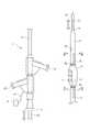
図1に本発明の一実施形態に係るカテーテル1の外観を模式的に示す。図2の(a)および(b)は、それぞれ図1の線IIA−IIAおよび線IIB−IIBに沿うカテーテル1の内部構造を模式的に示す断面図である。 FIG. 1 schematically shows the appearance of a catheter 1 according to an embodiment of the present invention. 2A and 2B are cross-sectional views schematically showing the internal structure of the catheter 1 along the lines IIA-IIA and IIB-IIB in FIG. 1, respectively.
カテーテル1は、その少なくとも一部が生体の血管内に挿入されるシャフト2を備えている。シャフト2は細長いため、一部の図示を省略している。シャフト2は、柔軟性を有して屈曲可能とされている。 The catheter 1 includes a
シャフト2の基端側には第1入口3が開口している。シャフト2の先端には第1出口4が開口している。シャフト2の内部には、第1入口3と第1出口4を連通する第1ルーメン5が延びている。 A first inlet 3 is open on the proximal end side of the
シャフト2の先端側の外周には、柔軟性を有する素材からなるバルーン6が設けられている。バルーン6は柔軟性を有する素材からなり、拡縮自在とされている。 A
バルーン6の表面には複数の電極7が設けられている。各電極7に接続された信号線8は、バルーン6の表面からシャフト2の外周面へ延び、シャフト2の内部へと進入する。図2に示すようにシャフト2の内部を延びる信号線8は、図1に示すようにシャフト2の基端側において外部へ導出され、コネクタ9に接続されている。すなわちコネクタ9は、信号線8を介して電極7と電気的に接続されている。 A plurality of
バルーン6と第1入口3の間には、シャフト2に複数の第1孔11が形成されている。バルーン6の第1出口4の間には、シャフト2に複数の第2孔12が形成されている。各第1孔11と各第2孔12は、第1ルーメン5に連通している。 A plurality of
シャフト2の基端側には、第2入口13が設けられている。シャフト2には第2出口14が形成されており、バルーン6と第1出口4の間において開口している。シャフト2の内部には、第2入口13と第2出口14を連通する第2ルーメン15が延びている。 A
アブレーションカテーテル16は、第1入口3から第1ルーメン5を通じて第1出口4へ挿通可能とされている。アブレーションカテーテル16の先端部には複数の電極17が設けられている。本実施形態のアブレーションカテーテル16は、電極17を通じて高周波電圧パルスを腎副交感神経に印加することにより、これを焼灼するためのものである。 The
腎動脈アブレーションを行なうに際しては、まず図示しない細径のガイドワイヤが第1入口3から第1ルーメン5を通じて第1出口4へ挿通される。このガイドワイヤを腎動脈内に挿入し、施術を要する腎副交感神経の付近までバルーン6を導く。図1に示すように、バルーン6の近傍にはX線を遮断するマーカ20が形成されているため、血管内におけるバルーン6の正確な位置を、X線画像を通じて把握することができる。 When performing renal artery ablation, a guide wire having a small diameter (not shown) is first inserted from the first inlet 3 to the
次いでシャフト2を腎動脈内に挿入し、ガイドワイヤに沿って進行させることにより、シャフト2の先端が施術を要する腎副交感神経の付近に配置される。ここでガイドワイヤを第1入口3を通じて抜き取り、代わりにアブレーションカテーテル16を第1入口に挿入する。 Next, the
アブレーションカテーテル16は、第1ルーメン5内を進行して第1出口4より突出する。アブレーションカテーテル16の電極17の施術箇所に対する位置は、第1入口3の側でアブレーションカテーテル16を押し引きすることにより調節することができる。 The
シャフト2の基端側には、圧力ポート18が設けられている。圧力ポート18は、シャフト2の内部に形成された通気路19に連通している。図3に示すように、通気路19はバルーン6の内部と連通している。図示しないシリンジを圧力ポート18に装着し、加圧操作を行なうことによりバルーン6が拡張し、減圧操作を行なうことによりバルーン6が収縮する。 A
図3は、腎動脈アブレーションを行なう場合における腎動脈壁50とカテーテル1の位置関係を、カテーテル1の内部構造とともに示す図である。同図においては、アブレーションカテーテル16の図示は省略し、第1孔11と第2孔12は、それぞれ1つずつ図示している。 FIG. 3 is a view showing the positional relationship between the
アブレーションカテーテル16の電極17が、施術対象である腎交感神経を焼灼可能な位置に配置されると、圧力ポート18に装着されたシリンジの加圧操作が行なわれ、バルーン6が拡張する。このときバルーン6の表面に設けられた電極7が腎動脈壁50の内壁に密着する。これにより生体によって異なる血管の太さによらず、腎交感神経の電位を電極7の電位として検出することが可能となる。腎交感神経の電位を示す信号は、信号線8を介して本発明の信号取得部としてのコネクタ9において取得される。 When the
コネクタ9を適宜の測定装置に接続することにより、腎交感神経の状態を監視しながら施術を行なうことが可能となる。電位信号の状態から神経焼灼が不十分であると判断されれば、アブレーションカテーテル16の電極17を通じて印加される高周波電圧パルスの印加時間や電圧値が適宜に調整される。よって術後数カ月の経過観察をせずとも、腎動脈アブレーションの施術中に神経焼灼の成否を判断することができる。 By connecting the
図3に示すように、血管内を流れる血液は、第1孔11から流入し、第1ルーメン5を通過して第2孔12から流出可能とされている。これにより、バルーン6の上流側と下流側を結ぶ血液の流路をシャフト2内に確保することができる。正確な腎交感神経の電位を取得するためには、バルーン6を十分に拡張させて電極7を腎動脈の内壁に密着させる必要がある。本実施形態の構成によれば、このように拡張されたバルーン6により腎臓へ向かう血流が阻止されて腎臓の機能不全が生ずる事態を回避することができる。 As shown in FIG. 3, blood flowing in the blood vessel can flow from the
したがって腎臓への血液供給を確保し、かつ腎交感神経の状態を監視しながら、確実に腎動脈アブレーションを遂行することが可能となる。 Therefore, it is possible to reliably perform renal artery ablation while ensuring blood supply to the kidney and monitoring the state of the renal sympathetic nerve.
本実施形態においては、第1孔11と第2孔12が第1ルーメン5に連通しているため、第1ルーメン5の一部が血流の迂回路として利用される。したがって当該迂回路を設けつつも、シャフト2が大型化することを回避できる。 In the present embodiment, since the
第2入口13には、例えば図示しないシリンジが装着され、薬液が注入される。当該薬液は第2ルーメン15を経由して第2出口14より放出され、腎臓へと送られる。第2出口14は、バルーン6の下流側に開口しているため、拡張したバルーン6により薬液の供給が阻止されることはない。したがって腎副交感神経の監視を伴う腎動脈アブレーションの施術中においても、必要な薬液の供給を継続することができる。 For example, a syringe (not shown) is attached to the
本実施形態においては、バルーン6の内部と連通する通気路19がシャフト2の内部に形成されている。そのため血管内に挿入されたシャフト2を移動させる際に通気路が損傷することを防止し、施術時において確実にバルーン6を拡張させることが可能となる。よって電極7を通じた腎交感神経の監視を確実に遂行することができる。 In the present embodiment, an
上記の実施形態は本発明の理解を容易にするためのものであって、本発明を限定するものではない。本発明は、その趣旨を逸脱することなく変更・改良され得ると共に、本発明にはその等価物が含まれることは明らかである。 The above embodiment is for facilitating understanding of the present invention, and does not limit the present invention. The present invention can be modified and improved without departing from the spirit of the present invention, and it is obvious that the present invention includes equivalents thereof.
第1孔11の数、位置、および形状は、図1に示したものに限られない。第1入口3とバルーン6の間に少なくとも1つ設けられている限りにおいて、仕様に応じて適宜に定められうる。 The number, position, and shape of the
第2孔12の数、位置、および形状は、図1に示したものに限られない。バルーン6と第1出口4の間に少なくとも1つ設けられている限りにおいて、仕様に応じて適宜に定められうる。 The number, position, and shape of the
第1孔11と第2孔12は、必ずしも第1ルーメン5に連通していることを要しない。シャフト2内に迂回する血液の流路を確保しうる限りにおいて、例えば第2ルーメン15に連通する構成としてもよい。また第1ルーメン5や第2ルーメン15とは異なるルーメンをシャフト2内に形成し、第1孔11と第2孔12が当該ルーメンに連通する構成としてもよい。 The
血液は、必ずしも第1孔11から流入し、第2孔12から流出することを要しない。シャフト2内に迂回する血液の流路を確保しうる限りにおいて、施術内容やシャフト2が挿入される血管に応じ、血液が第2孔12から流入し、第1孔11から流出する構成とすることもできる。 The blood does not necessarily need to flow from the
第1ルーメン5は、必ずしもアブレーションカテーテル16を挿通させるために用いられることを要しない。例えば第1ルーメン5を生理食塩水で満たし、カテーテル1を血圧の測定に用いることができる。 The
第1ルーメン5にアブレーションカテーテル16を挿通させることに加えて、あるいは代えて、図4の(a)に示すように、アブレーション用に通電可能な電極17がバルーン6の表面に設けられる構成としてもよい。 In addition to or instead of inserting the
電極7および電極17の数およびバルーン6上における配置は任意に定められうる。電極17については、図4の(b)に示すように、バルーン6の周方向について複数箇所に設けられるようにすることにより、対象物の焼灼をより確実に行なうことができる。 The number of the
電極7は、必ずしも腎交感神経の電位を取得するために用いられることを要しない。カテーテルを用いた施術対象物の状態を監視するために、適宜の目的で用いられうる。 The
第2入口13、第2出口14、および第2ルーメン15は、特に必要がなければ省略することができる。また通気路19は、シャフト2の外部に形成してもよい。 The
1:カテーテル、2:シャフト、3:第1入口、4:第1出口、5:第1ルーメン、6:バルーン、7:電極、9:コネクタ、11:第1孔、12:第2孔、13:第2入口、14:第2出口、15:第2ルーメン、16:アブレーションカテーテル、19:通気路 1: catheter, 2: shaft, 3: first inlet, 4: first outlet, 5: first lumen, 6: balloon, 7: electrode, 9: connector, 11: first hole, 12: second hole, 13: second inlet, 14: second outlet, 15: second lumen, 16: ablation catheter, 19: vent
Claims (6)
Translated fromJapanese第1入口と、
前記シャフトに形成された第1出口と、
前記シャフトの内部を延び、前記第1入口と前記第1出口を連通する第1ルーメンと、
前記シャフトの外周に設けられ、拡縮自在とされたバルーンと、
前記バルーンの表面に設けられた電極と、
前記電極と電気的に接続された信号取出部と、
前記バルーンと前記第1入口の間において前記シャフトに形成された第1孔と、
前記バルーンと前記第1出口の間において前記シャフトに形成された第2孔とを備え、
血管内を流れる血液は、前記第1孔と前記第2孔の一方から流入し、他方から流出可能とされている、カテーテル。A shaft that is at least partially inserted into a blood vessel of a living body;
The first entrance,
A first outlet formed in the shaft;
A first lumen extending through the shaft and communicating the first inlet and the first outlet;
A balloon provided on the outer periphery of the shaft and capable of being expanded and contracted;
An electrode provided on the surface of the balloon;
A signal extraction portion electrically connected to the electrode;
A first hole formed in the shaft between the balloon and the first inlet;
A second hole formed in the shaft between the balloon and the first outlet;
A catheter in which blood flowing in a blood vessel can flow in from one of the first hole and the second hole and flow out from the other.
前記シャフトに形成された第2出口と、
前記シャフトの内部を延び、前記第2入口と前記第2出口を連通する第2ルーメンをさらに備え、
前記第2出口は、前記バルーンと前記第1出口の間に開口している、請求項1または2に記載のカテーテル。The second entrance,
A second outlet formed in the shaft;
A second lumen extending through the shaft and communicating the second inlet and the second outlet;
The catheter according to claim 1 or 2, wherein the second outlet is opened between the balloon and the first outlet.
Priority Applications (4)
| Application Number | Priority Date | Filing Date | Title |
|---|---|---|---|
| JP2012201653AJP2014054430A (en) | 2012-09-13 | 2012-09-13 | Catheter |
| US14/018,002US20140074089A1 (en) | 2012-09-13 | 2013-09-04 | Catheter |
| CN201310400627.1ACN103654763A (en) | 2012-09-13 | 2013-09-05 | Catheter |
| EP13183167.9AEP2708181A1 (en) | 2012-09-13 | 2013-09-05 | Renal denervation catheter |
Applications Claiming Priority (1)
| Application Number | Priority Date | Filing Date | Title |
|---|---|---|---|
| JP2012201653AJP2014054430A (en) | 2012-09-13 | 2012-09-13 | Catheter |
Publications (1)
| Publication Number | Publication Date |
|---|---|
| JP2014054430Atrue JP2014054430A (en) | 2014-03-27 |
Family
ID=49150756
Family Applications (1)
| Application Number | Title | Priority Date | Filing Date |
|---|---|---|---|
| JP2012201653APendingJP2014054430A (en) | 2012-09-13 | 2012-09-13 | Catheter |
Country Status (4)
| Country | Link |
|---|---|
| US (1) | US20140074089A1 (en) |
| EP (1) | EP2708181A1 (en) |
| JP (1) | JP2014054430A (en) |
| CN (1) | CN103654763A (en) |
Families Citing this family (58)
| Publication number | Priority date | Publication date | Assignee | Title |
|---|---|---|---|---|
| US8241274B2 (en) | 2000-01-19 | 2012-08-14 | Medtronic, Inc. | Method for guiding a medical device |
| US7756583B2 (en) | 2002-04-08 | 2010-07-13 | Ardian, Inc. | Methods and apparatus for intravascularly-induced neuromodulation |
| US8150519B2 (en) | 2002-04-08 | 2012-04-03 | Ardian, Inc. | Methods and apparatus for bilateral renal neuromodulation |
| US7617005B2 (en) | 2002-04-08 | 2009-11-10 | Ardian, Inc. | Methods and apparatus for thermally-induced renal neuromodulation |
| US8347891B2 (en) | 2002-04-08 | 2013-01-08 | Medtronic Ardian Luxembourg S.A.R.L. | Methods and apparatus for performing a non-continuous circumferential treatment of a body lumen |
| US7653438B2 (en) | 2002-04-08 | 2010-01-26 | Ardian, Inc. | Methods and apparatus for renal neuromodulation |
| JP5219518B2 (en) | 2004-12-09 | 2013-06-26 | ザ ファウンドリー, エルエルシー | Aortic valve repair |
| US20070021803A1 (en) | 2005-07-22 | 2007-01-25 | The Foundry Inc. | Systems and methods for neuromodulation for treatment of pain and other disorders associated with nerve conduction |
| US20080039746A1 (en) | 2006-05-25 | 2008-02-14 | Medtronic, Inc. | Methods of using high intensity focused ultrasound to form an ablated tissue area containing a plurality of lesions |
| TWI513451B (en) | 2010-10-25 | 2015-12-21 | Medtronic Ardian Luxembourg | Devices, systems and methods for evaluation and feedback of neuromodulation treatment |
| JP5759615B2 (en) | 2011-04-08 | 2015-08-05 | コヴィディエン リミテッド パートナーシップ | Iontophoretic catheter system and method for renal sympathetic denervation and iontophoretic drug delivery |
| WO2012148969A2 (en) | 2011-04-25 | 2012-11-01 | Brian Kelly | Apparatus and methods related to constrained deployment of cryogenic balloons for limited cryogenic ablation of vessel walls |
| EP2775899B1 (en) | 2011-11-07 | 2017-08-23 | Medtronic Ardian Luxembourg S.à.r.l. | Endovascular nerve monitoring devices and associated systems |
| US9597018B2 (en) | 2012-03-08 | 2017-03-21 | Medtronic Ardian Luxembourg S.A.R.L. | Biomarker sampling in the context of neuromodulation devices, systems, and methods |
| CA2881462C (en) | 2012-08-09 | 2020-07-14 | University Of Iowa Research Foundation | Catheters, catheter systems, and methods for puncturing through a tissue structure |
| EP2968919B1 (en) | 2013-03-15 | 2021-08-25 | Medtronic Ardian Luxembourg S.à.r.l. | Controlled neuromodulation systems |
| US9339332B2 (en) | 2013-08-30 | 2016-05-17 | Medtronic Ardian Luxembourg S.A.R.L. | Neuromodulation catheters with nerve monitoring features for transmitting digital neural signals and associated systems and methods |
| US9326816B2 (en) | 2013-08-30 | 2016-05-03 | Medtronic Ardian Luxembourg S.A.R.L. | Neuromodulation systems having nerve monitoring assemblies and associated devices, systems, and methods |
| EP3091921B1 (en) | 2014-01-06 | 2019-06-19 | Farapulse, Inc. | Apparatus for renal denervation ablation |
| US9579149B2 (en) | 2014-03-13 | 2017-02-28 | Medtronic Ardian Luxembourg S.A.R.L. | Low profile catheter assemblies and associated systems and methods |
| US10610292B2 (en) | 2014-04-25 | 2020-04-07 | Medtronic Ardian Luxembourg S.A.R.L. | Devices, systems, and methods for monitoring and/or controlling deployment of a neuromodulation element within a body lumen and related technology |
| US10709490B2 (en) | 2014-05-07 | 2020-07-14 | Medtronic Ardian Luxembourg S.A.R.L. | Catheter assemblies comprising a direct heating element for renal neuromodulation and associated systems and methods |
| EP3495018B1 (en) | 2014-05-07 | 2023-09-06 | Farapulse, Inc. | Apparatus for selective tissue ablation |
| WO2015175944A1 (en) | 2014-05-16 | 2015-11-19 | Gary Long | Methods and apparatus for multi-catheter tissue ablation |
| EP3154463B1 (en) | 2014-06-12 | 2019-03-27 | Farapulse, Inc. | Apparatus for rapid and selective transurethral tissue ablation |
| WO2015192018A1 (en) | 2014-06-12 | 2015-12-17 | Iowa Approach Inc. | Method and apparatus for rapid and selective tissue ablation with cooling |
| US11154712B2 (en) | 2014-08-28 | 2021-10-26 | Medtronic Ardian Luxembourg S.A.R.L. | Methods for assessing efficacy of renal neuromodulation and associated systems and devices |
| WO2016054379A1 (en) | 2014-10-01 | 2016-04-07 | Medtronic Ardian Luxembourg S.A.R.L. | Systems and methods for evaluating neuromodulation therapy via hemodynamic responses |
| EP3206613B1 (en) | 2014-10-14 | 2019-07-03 | Farapulse, Inc. | Apparatus for rapid and safe pulmonary vein cardiac ablation |
| US10667736B2 (en) | 2014-12-17 | 2020-06-02 | Medtronic Ardian Luxembourg S.A.R.L. | Systems and methods for assessing sympathetic nervous system tone for neuromodulation therapy |
| US12144541B2 (en) | 2016-01-05 | 2024-11-19 | Boston Scientific Scimed, Inc. | Systems, apparatuses and methods for delivery of ablative energy to tissue |
| US10130423B1 (en) | 2017-07-06 | 2018-11-20 | Farapulse, Inc. | Systems, devices, and methods for focal ablation |
| US10660702B2 (en) | 2016-01-05 | 2020-05-26 | Farapulse, Inc. | Systems, devices, and methods for focal ablation |
| US10172673B2 (en) | 2016-01-05 | 2019-01-08 | Farapulse, Inc. | Systems devices, and methods for delivery of pulsed electric field ablative energy to endocardial tissue |
| US20170189097A1 (en) | 2016-01-05 | 2017-07-06 | Iowa Approach Inc. | Systems, apparatuses and methods for delivery of ablative energy to tissue |
| EP3471631A4 (en) | 2016-06-16 | 2020-03-04 | Farapulse, Inc. | GUIDE WIRE DISTRIBUTION SYSTEMS, APPARATUSES AND METHODS |
| US10231784B2 (en) | 2016-10-28 | 2019-03-19 | Medtronic Ardian Luxembourg S.A.R.L. | Methods and systems for optimizing perivascular neuromodulation therapy using computational fluid dynamics |
| US9987081B1 (en) | 2017-04-27 | 2018-06-05 | Iowa Approach, Inc. | Systems, devices, and methods for signal generation |
| US10617867B2 (en) | 2017-04-28 | 2020-04-14 | Farapulse, Inc. | Systems, devices, and methods for delivery of pulsed electric field ablative energy to esophageal tissue |
| JP7586706B2 (en) | 2017-09-12 | 2024-11-19 | ボストン サイエンティフィック サイムド,インコーポレイテッド | Systems, devices and methods for focal ventricular ablation - Patents.com |
| US12082917B2 (en) | 2018-01-24 | 2024-09-10 | Medtronic Ireland Manufacturing Unlimited Company | Systems, devices, and methods for assessing efficacy of renal neuromodulation therapy |
| EP3749238B1 (en) | 2018-02-08 | 2023-08-16 | Farapulse, Inc. | Apparatus for controlled delivery of pulsed electric field ablative energy to tissue |
| US20190336198A1 (en) | 2018-05-03 | 2019-11-07 | Farapulse, Inc. | Systems, devices, and methods for ablation using surgical clamps |
| CN112087978B (en) | 2018-05-07 | 2023-01-17 | 波士顿科学医学有限公司 | epicardial ablation catheter |
| WO2019217433A1 (en) | 2018-05-07 | 2019-11-14 | Farapulse, Inc. | Systems, apparatuses and methods for delivery of ablative energy to tissue |
| CN119074196A (en) | 2018-05-07 | 2024-12-06 | 波士顿科学医学有限公司 | Systems, devices and methods for filtering high voltage noise induced by pulsed electric field ablation |
| US11633120B2 (en) | 2018-09-04 | 2023-04-25 | Medtronic Ardian Luxembourg S.A.R.L. | Systems and methods for assessing efficacy of renal neuromodulation therapy |
| US10687892B2 (en) | 2018-09-20 | 2020-06-23 | Farapulse, Inc. | Systems, apparatuses, and methods for delivery of pulsed electric field ablative energy to endocardial tissue |
| EP3952972A4 (en)* | 2019-04-08 | 2023-06-21 | Udayan Patel | Inflatable balloon over catheter with bypass passageway |
| US10625080B1 (en) | 2019-09-17 | 2020-04-21 | Farapulse, Inc. | Systems, apparatuses, and methods for detecting ectopic electrocardiogram signals during pulsed electric field ablation |
| US11065047B2 (en) | 2019-11-20 | 2021-07-20 | Farapulse, Inc. | Systems, apparatuses, and methods for protecting electronic components from high power noise induced by high voltage pulses |
| US11497541B2 (en) | 2019-11-20 | 2022-11-15 | Boston Scientific Scimed, Inc. | Systems, apparatuses, and methods for protecting electronic components from high power noise induced by high voltage pulses |
| US10842572B1 (en) | 2019-11-25 | 2020-11-24 | Farapulse, Inc. | Methods, systems, and apparatuses for tracking ablation devices and generating lesion lines |
| CN113679398B (en)* | 2020-05-14 | 2023-04-11 | 上海悦灵医疗科技有限公司 | Trigeminal semilunar junction compression device |
| WO2022020478A1 (en) | 2020-07-24 | 2022-01-27 | Boston Scientific Scimed Inc | Electric field application for single shot cardiac ablation by irreversible electroporation |
| US12310652B2 (en) | 2020-07-24 | 2025-05-27 | Boston Scientific Scimed, Inc. | Hybrid electroporation ablation catheter |
| WO2022072385A2 (en) | 2020-09-30 | 2022-04-07 | Boston Scientific Scimed Inc | Pretreatment waveform for irreversible electroporation |
| JP2024504184A (en) | 2021-01-27 | 2024-01-30 | ボストン サイエンティフィック サイムド,インコーポレイテッド | Voltage-controlled pulse sequence for irreversible electroporation ablation |
Citations (11)
| Publication number | Priority date | Publication date | Assignee | Title |
|---|---|---|---|---|
| US5090960A (en)* | 1990-01-12 | 1992-02-25 | Don Michael T Anthony | Regional perfusion dissolution catheter |
| JPH09117510A (en)* | 1995-10-26 | 1997-05-06 | Buaayu:Kk | Infusion catheter |
| JPH11225985A (en)* | 1998-02-16 | 1999-08-24 | Toshiba Corp | MRI probe |
| JP2000279524A (en)* | 1999-03-30 | 2000-10-10 | Junichi Tanaka | Catheter |
| US6193685B1 (en)* | 1996-11-26 | 2001-02-27 | Schneider (Usa) Inc. | Perfusion catheter |
| US6540765B1 (en)* | 2000-09-11 | 2003-04-01 | Robert F. Malacoff | Apparatus for positioning a cardiac pacer lead |
| US20040243118A1 (en)* | 2001-06-01 | 2004-12-02 | Ayers Gregory M. | Device and method for positioning a catheter tip for creating a cryogenic lesion |
| US20060195135A1 (en)* | 2005-02-25 | 2006-08-31 | Ihab Ayoub | Pass-through catheter |
| US20080255642A1 (en)* | 2006-06-28 | 2008-10-16 | Ardian, Inc. | Methods and systems for thermally-induced renal neuromodulation |
| WO2011155424A1 (en)* | 2010-06-08 | 2011-12-15 | 東レ株式会社 | Catheter for measuring electric potential |
| US20120029512A1 (en)* | 2010-07-30 | 2012-02-02 | Willard Martin R | Balloon with surface electrodes and integral cooling for renal nerve ablation |
Family Cites Families (7)
| Publication number | Priority date | Publication date | Assignee | Title |
|---|---|---|---|---|
| US5871449A (en)* | 1996-12-27 | 1999-02-16 | Brown; David Lloyd | Device and method for locating inflamed plaque in an artery |
| US7653438B2 (en) | 2002-04-08 | 2010-01-26 | Ardian, Inc. | Methods and apparatus for renal neuromodulation |
| US8347891B2 (en)* | 2002-04-08 | 2013-01-08 | Medtronic Ardian Luxembourg S.A.R.L. | Methods and apparatus for performing a non-continuous circumferential treatment of a body lumen |
| US8128617B2 (en)* | 2008-05-27 | 2012-03-06 | Boston Scientific Scimed, Inc. | Electrical mapping and cryo ablating with a balloon catheter |
| US20110190727A1 (en)* | 2010-02-02 | 2011-08-04 | Boston Scientific Scimed, Inc. | Intervascular catheter, system and method |
| US20120065554A1 (en)* | 2010-09-09 | 2012-03-15 | Michael Pikus | Dual Balloon Ablation Catheter with Vessel Deformation Arrangement for Renal Nerve Ablation |
| US8998893B2 (en)* | 2010-12-07 | 2015-04-07 | Boaz Avitall | Catheter systems for cardiac arrhythmia ablation |
- 2012
- 2012-09-13JPJP2012201653Apatent/JP2014054430A/enactivePending
- 2013
- 2013-09-04USUS14/018,002patent/US20140074089A1/ennot_activeAbandoned
- 2013-09-05EPEP13183167.9Apatent/EP2708181A1/ennot_activeWithdrawn
- 2013-09-05CNCN201310400627.1Apatent/CN103654763A/enactivePending
Patent Citations (11)
| Publication number | Priority date | Publication date | Assignee | Title |
|---|---|---|---|---|
| US5090960A (en)* | 1990-01-12 | 1992-02-25 | Don Michael T Anthony | Regional perfusion dissolution catheter |
| JPH09117510A (en)* | 1995-10-26 | 1997-05-06 | Buaayu:Kk | Infusion catheter |
| US6193685B1 (en)* | 1996-11-26 | 2001-02-27 | Schneider (Usa) Inc. | Perfusion catheter |
| JPH11225985A (en)* | 1998-02-16 | 1999-08-24 | Toshiba Corp | MRI probe |
| JP2000279524A (en)* | 1999-03-30 | 2000-10-10 | Junichi Tanaka | Catheter |
| US6540765B1 (en)* | 2000-09-11 | 2003-04-01 | Robert F. Malacoff | Apparatus for positioning a cardiac pacer lead |
| US20040243118A1 (en)* | 2001-06-01 | 2004-12-02 | Ayers Gregory M. | Device and method for positioning a catheter tip for creating a cryogenic lesion |
| US20060195135A1 (en)* | 2005-02-25 | 2006-08-31 | Ihab Ayoub | Pass-through catheter |
| US20080255642A1 (en)* | 2006-06-28 | 2008-10-16 | Ardian, Inc. | Methods and systems for thermally-induced renal neuromodulation |
| WO2011155424A1 (en)* | 2010-06-08 | 2011-12-15 | 東レ株式会社 | Catheter for measuring electric potential |
| US20120029512A1 (en)* | 2010-07-30 | 2012-02-02 | Willard Martin R | Balloon with surface electrodes and integral cooling for renal nerve ablation |
Also Published As
| Publication number | Publication date |
|---|---|
| US20140074089A1 (en) | 2014-03-13 |
| EP2708181A1 (en) | 2014-03-19 |
| CN103654763A (en) | 2014-03-26 |
Similar Documents
| Publication | Publication Date | Title |
|---|---|---|
| JP2014054430A (en) | Catheter | |
| JP6797173B2 (en) | Medical device for fluid communication | |
| JP6322402B2 (en) | Guiding catheter | |
| CN105392435B (en) | Renal nerve ablation catheter with twisting sacculus | |
| JP6522657B2 (en) | Patient Access Device with Gas Removal Function | |
| CN104507406B (en) | High frequency knife | |
| CN105188588B (en) | The opening open irrigated ablation catheters cooled down with near-end | |
| JP2015112114A (en) | Catheter for measuring nerve potential | |
| CN105899157B (en) | Tear Resistant Flexible Circuit Assemblies | |
| WO2014162660A1 (en) | Monitoring device and monitoring device kit | |
| US9750564B2 (en) | Flexible catheter for high-frequency therapy of biological tissue and method of using same | |
| JP6282209B2 (en) | Chemical ablation device and chemical ablation system | |
| CN105030325A (en) | Ablation Catheter with Dedicated Fluid Path and Needle Centering Insert | |
| CN107750146A (en) | It is open to rinse ablation catheter | |
| EP3037054A1 (en) | Mapping ablation catheter | |
| JP2013198691A (en) | Nerve stimulation electrode and nerve stimulation system | |
| JP7368599B2 (en) | Chemical injection needles and chemical injection needle systems | |
| US12440165B2 (en) | Catheter for neural measurements and treatment and related systems and methods | |
| US20230040877A1 (en) | Catheter for neural measurements and treatment and related systems and methods | |
| US20240238620A1 (en) | Catheters with balloons on which are located electrodes | |
| US20230310053A1 (en) | Systems and methods for performing a denervation procedure and determining the efficacy thereof | |
| EP4493090A1 (en) | Systems and methods for performing a denervation procedure and determining the efficacy thereof | |
| CN116407764A (en) | Medical catheter, sheath, catheter assembly and medical system | |
| PL227986B1 (en) | Multipurpose, electrophysiological diagnostic catheter for treatments in electrocardiology | |
| JP2017164310A (en) | Balloon catheter, adrenal tumor chemical ablation treatment device and adrenal vein blood collection device |
Legal Events
| Date | Code | Title | Description |
|---|---|---|---|
| A621 | Written request for application examination | Free format text:JAPANESE INTERMEDIATE CODE: A621 Effective date:20150225 | |
| A977 | Report on retrieval | Free format text:JAPANESE INTERMEDIATE CODE: A971007 Effective date:20151211 | |
| A131 | Notification of reasons for refusal | Free format text:JAPANESE INTERMEDIATE CODE: A131 Effective date:20151222 | |
| A02 | Decision of refusal | Free format text:JAPANESE INTERMEDIATE CODE: A02 Effective date:20160419 |