JP2014044641A - Crime information management device and crime information management system - Google Patents
Crime information management device and crime information management systemDownload PDFInfo
- Publication number
- JP2014044641A JP2014044641AJP2012187585AJP2012187585AJP2014044641AJP 2014044641 AJP2014044641 AJP 2014044641AJP 2012187585 AJP2012187585 AJP 2012187585AJP 2012187585 AJP2012187585 AJP 2012187585AJP 2014044641 AJP2014044641 AJP 2014044641A
- Authority
- JP
- Japan
- Prior art keywords
- crime
- information
- information management
- crime information
- terminal
- Prior art date
- Legal status (The legal status is an assumption and is not a legal conclusion. Google has not performed a legal analysis and makes no representation as to the accuracy of the status listed.)
- Pending
Links
Images


Landscapes
- Alarm Systems (AREA)
- Mobile Radio Communication Systems (AREA)
- Telephone Function (AREA)
- Telephonic Communication Services (AREA)
Abstract
Translated fromJapaneseDescription
Translated fromJapanese本発明は、犯罪情報管理装置および犯罪情報管理システムに関する。 The present invention relates to a crime information management device and a crime information management system.
近年、犯罪に関する多様な装置およびシステムが考案されている。 In recent years, various devices and systems relating to crime have been devised.
例えば、犯罪の防止や抑制のための提案の一例には、特許文献1がある。特許文献1は、ATMコーナーなどの付近に、パスワードを盗むために設置した盗撮カメラからの電波を受信し、電波を受信した際にアラート通報し、その前後の時間の監視カメラの映像を監視センタ用装置に送信する、などのシステムである。 For example, there is Patent Literature 1 as an example of a proposal for prevention and suppression of crime. Patent Document 1 receives a radio wave from a voyeur camera installed to steal a password in the vicinity of an ATM corner or the like, alerts the user when the radio wave is received, and uses the video of the monitoring camera before and after that for the monitoring center. It is a system such as transmitting to a device.
また、犯罪発生時の連絡や救助要請のための提案の一例には、特許文献2がある。特許文献2は、GPS(Global Positioning System)機能付き携帯端末にカメラ、マイク、およびブザーを取り付け、緊急時操作を行うと、これらが作動し、GPS機能で取得した位置情報とともに、画像および音声データを警備会社サーバに送信する。警備会社サーバは、受信した位置情報をもとに、近くにいる警備員の携帯端末を検索し、当該の携帯端末に救助要請の連絡をし、救助要請を受信した警備員を連絡者の救助に向かわせる、などのシステムである。 Moreover, there is
さらに、犯罪発生時に犯罪に巻き込まれないようにするための提案の一例には、特許文献3がある。特許文献3は、予めグループ化して登録された複数の通信端末において、緊急事態が発生した危険エリア内に位置する通信端末を抽出し、当該通信端末が属するグループの通信端末に緊急情報を通知し、危険エリアに入った通信端末に対して注意を促すための特定動作を行う信号を送信する、などのシステムである。 Furthermore, there exists patent document 3 as an example of the proposal for preventing it from being involved in a crime when a crime occurs. Patent Document 3 extracts a communication terminal located in a dangerous area where an emergency has occurred from a plurality of communication terminals registered in a group in advance, and notifies the emergency information to the communication terminal of the group to which the communication terminal belongs. And a system for transmitting a signal for performing a specific operation to call attention to a communication terminal that has entered a danger area.
しかしながら、特許文献1は、監視対象(図13の監視対象装置2)が特定されていて、監視対象以外の犯罪情報を入手することが困難であり、監視対象が不特定である一般的な犯罪の犯罪情報を入手することは困難であった。 However, Patent Document 1 is a general crime in which a monitoring target (monitoring
特許文献2は、犯罪に遭った本人の携帯端末(図14のユーザ携帯端末10)から犯罪情報を入手するため、当該の携帯端末のカメラが、犯人や犯行の様子を捉えられない可能性がある。 Since
特許文献3は、契約者(図15の携帯端末20と30)に対する、犯罪(緊急事態)の発生や、危険エリアに入った通信端末に対する注意などの連絡であり、犯人や犯行の様子を捉えることはできなかった。 Patent Document 3 is a communication to a contractor (mobile terminals 20 and 30 in FIG. 15) regarding the occurrence of a crime (emergency) or a caution about a communication terminal that has entered a dangerous area, and captures the state of a criminal or a crime. I couldn't.
これらを鑑み、犯行前後の犯人および犯行の様子を効果的に捉え、警察への連絡および情報提供を適切に行うことができ、また、犯罪発生を抑制することができる、携帯端末と監視カメラを利用した犯罪情報管理装置および犯罪情報管理システムを提供することにある。 In view of these, a portable terminal and a surveillance camera that can effectively capture the criminal before and after the crime and the state of the crime, can appropriately contact the police and provide information, and can suppress the occurrence of crime. It is to provide a crime information management device and a crime information management system that are used.
本発明の犯罪情報管理装置および犯罪情報管理システムは、犯罪情報を送信する犯罪情報送信機能を有する携帯通信端末と、前記携帯通信端末を通信制御する基地局と、監視カメラと、前記監視カメラが撮影した動画もしくは画像である撮影データを記憶する記憶制御装置と、前記携帯通信端末および前記記憶制御装置と通信する犯罪情報管理装置と、を備えた犯罪情報管理システムであって、前記携帯通信端末は、犯罪情報を送信する操作がなされると、自端末の位置情報である端末位置情報と、自端末を一意に示す端末コードと、を取得し、少なくとも、前記端末位置情報と、前記端末コードと、からなる第1の犯罪情報を、前記基地局を介し、前記犯罪情報管理装置に送信し、犯罪が発生したことを示す犯罪警報を前記犯罪情報管理装置から受信し、前記犯罪情報管理装置は、前記第1の犯罪情報を受信すると、前記第1の犯罪情報を一意とする管理コードを生成し、前記第1の犯罪情報を受信した受信時刻とともに記憶し、前記犯罪警報を前記携帯通信端末に送信し、前記端末位置情報の近傍に設置された前記監視カメラの前記撮影データを記憶している前記記憶制御装置を検索し、当該の記憶制御装置に第1の検索条件とともに撮影データの要求を送信し、前記撮影データの要求に対する返信である当該の前記撮影データを受信し、当該の前記撮影データを前記管理コードに関連付けて記憶し、前記記憶制御装置は、前記撮影データの要求を受信すると、前記第1の検索条件により決定する第2の検索条件を満たす前記撮影データを検索し、当該の前記撮影データを前記犯罪情報管理装置に送信することを特徴とする。 The crime information management apparatus and crime information management system according to the present invention include a mobile communication terminal having a crime information transmission function for transmitting crime information, a base station for controlling communication of the mobile communication terminal, a monitoring camera, and the monitoring camera. A crime information management system comprising: a storage control device that stores shooting data that is a captured moving image or image; and a crime information management device that communicates with the portable communication terminal and the storage control device, wherein the portable communication terminal When an operation of transmitting crime information is performed, terminal location information that is location information of the terminal and a terminal code that uniquely indicates the terminal are acquired, and at least the terminal location information and the terminal code The crime information management device transmits a crime warning indicating that a crime has occurred to the crime information management device via the base station. When the first crime information is received, the crime information management device generates a management code that makes the first crime information unique, and stores it together with a reception time when the first crime information is received. The crime alarm is transmitted to the mobile communication terminal, the storage control device storing the shooting data of the monitoring camera installed in the vicinity of the terminal position information is searched, and the storage control device is searched. A request for shooting data is transmitted together with a first search condition, the shooting data that is a reply to the request for shooting data is received, the shooting data is stored in association with the management code, and the storage control When the apparatus receives the request for the photographing data, the apparatus searches the photographing data satisfying a second search condition determined by the first search condition, and the relevant photographing data is And transmits sin information management device.
本発明によれば、犯行前後の犯人および犯行の様子を効果的に捉え、警察への連絡および情報提供を適切に行うことができ、また、犯罪発生を抑制することができる。 ADVANTAGE OF THE INVENTION According to this invention, the criminal before and after a crime and the state of a crime can be caught effectively, a police can be contacted and information provision can be performed appropriately, and crime occurrence can be suppressed.
本発明の第1の実施形態について、図を参照して説明する。 A first embodiment of the present invention will be described with reference to the drawings.
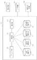
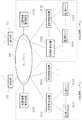
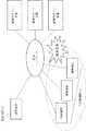
図1は本発明の実施形態である犯罪情報管理システムを示すシステム構成図である。 FIG. 1 is a system configuration diagram showing a crime information management system according to an embodiment of the present invention.
犯罪情報管理システムは、少なくとも、緊急通報を行う緊急通報機能を有する、携帯通信端末400(以下、端末400と記述)と、端末400を通信制御する基地局100と、動画もしくは画像を撮影する監視カメラ520と、監視カメラ520が撮影した撮影データ(動画もしくは画像のデータ)を記憶し、記憶している撮影データを検索し、当該の撮影データを送信する記憶制御装置510と、記憶制御装置510および基地局100を介し、端末400と通信を行い、犯罪情報を記憶し、管理する犯罪情報管理装置300(以下、管理装置300と記述)と、これらの装置を結ぶネットワーク200と、で構成されている。 The crime information management system includes at least a mobile communication terminal 400 (hereinafter referred to as a terminal 400) having an emergency call function for making an emergency call, a
ここで、端末400を、緊急通報を行う通報端末400Aと、その他の契約ユーザの端末を示すユーザ端末400Bと、警備会社関係者の端末を示す警備端末400Cと、に分けて説明する。 Here, the terminal 400 will be described by being divided into a
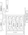
図2は、管理装置300の機能構成を示す図である。 FIG. 2 is a diagram illustrating a functional configuration of the
管理装置300は、少なくとも、装置本体310と、キーボード、マウス、タッチパネルなどの入力装置320と、ディスプレイなどの表示装置330と、スピーカなどの音声出力装置340と、で構成される。これらの装置の一部もしく全てを、装置本体310に内蔵してもよいし、一体型パソコンやタブレット型携帯端末などで代用してもよい。 The
装置本体310は、少なくとも、データを記憶する次の4つのDB(データベース)と、これらを制御し、データの処理および送受信を行う制御部311と、位置情報を地図上のマークするマッピング部316と、記憶している情報を集計する集計部317と、で構成される。 The apparatus
第1のDBは、地図情報DB312で、少なくとも、緯度および経度と関連付いた地図情報を記憶している。 The first DB is a
第2のDBは、利用者情報管理DB313(以下、利用者DB313と記述)で、少なくとも、電話番号などの端末400を一意にする端末コードと、メールアドレスなどの配信先と、契約者や警備会社関係者などを区分する情報などを記憶している。 The second DB is a user information management DB 313 (hereinafter referred to as a user DB 313). At least a terminal code such as a telephone number that makes the terminal 400 unique, a delivery destination such as an e-mail address, a contractor, and a guard Stores information that categorizes company personnel.
第3のDBは、監視カメラ情報管理DB314(以下、カメラDB314と記述)で、少なくとも、記憶制御装置510とおよび監視カメラ520を一意とするカメラコードと、緯度や経度、建物内の設置場所や階数などの監視カメラ520の設置場所を示す位置情報と、を記憶している。 The third DB is a monitoring camera information management DB 314 (hereinafter referred to as camera DB 314). At least the camera code that uniquely identifies the
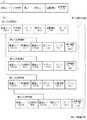
図3は、犯罪情報管理DB315(以下、犯罪DB315と記述)に記憶しているデータ構成の一例と、記憶している情報およびその関連付けのイメージを示す図である。 FIG. 3 is a diagram showing an example of the data configuration stored in the crime information management DB 315 (hereinafter referred to as the crime DB 315), the stored information, and an image of the association.
第4のDBは、犯罪DB315で、図3(a)に示すように、少なくとも、端末400の位置情報と、端末コードまたはカメラコードからなる識別コードと、データを受信した受信時刻と、識別コードと受信時刻との組合せにおいて一意となる管理コードと、識別コードに関連付いた端末400または記憶制御装置510からの音声を含む撮影データと、親の管理コードを示す親コードと、を記憶している。 The fourth DB is a
犯罪DB315は、記憶している情報により、第1、第2および第3の犯罪情報に分けられ、管理コードと、親コードと、の一致により、親子関係が関連付けられ、図3(b)は関連付けた情報の親子関係のイメージである。なお、3つの情報を、個々に3つのDBで構成してもよい。 The
端末400は、スマートフォンなどの携帯電話であり、緊急通報機能は、例えば、専用サイトからソフトウエアをダウンロードしたり、専用部品を取り付けたり、することで端末400に付加される。あるいは、警備会社と契約すると、緊急通報機能付きの携帯通信端末が提供される。この緊急通報機能は、通報先である管理装置300への通信アドレスや、端末400での処理手段、などを記憶している。 The terminal 400 is a mobile phone such as a smartphone, and the emergency call function is added to the terminal 400 by, for example, downloading software from a dedicated site or attaching a dedicated part. Alternatively, a contract with a security company provides a mobile communication terminal with an emergency call function. This emergency call function stores a communication address to the
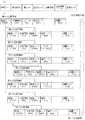
図4a〜図4cは、本システムの処理フローを示す図である。 4a to 4c are diagrams showing a processing flow of the present system.
通報端末400Aおよび専用部品におけるスイッチやキーなどの部位を押したり、引いたり、などの緊急通報の操作がなされると、通報端末400Aは、GPS機能により自端末の位置情報である位置情報400Aを取得する。そして、少なくとも、通報端末400Aが記憶している端末コード400Aと、位置情報400Aと、からなる第1の犯罪情報を管理装置300に送信する(ステップS101)。 When an emergency call operation such as pressing or pulling a part such as a switch or key in the
ここで、位置情報400Aを取得する手段は、通報端末400AのGPS機能の他に次の2つの手段が考えられ、GPS機能が無効となる場所では、次の2つの手段により位置情報を取得する。 Here, as the means for obtaining the
第1の手段は、監視カメラが、当該の監視カメラを特定できる情報、例えば、カメラコード、を含む電波を発信し、通報端末400Aがその電波を受信し、犯罪管理装置300に送信する。犯罪管理装置300は、カメラ情報DB314において、受信したカメラコードと一致する監視カメラを検索し、当該の監視カメラの設置場所を位置情報400Aとする手段である。 In the first means, the surveillance camera transmits a radio wave including information that can identify the surveillance camera, for example, a camera code, and the
第2の手段は、基地局100に、例えば、端末400の位置情報を取得する位置情報管理サーバを設置し、通報端末400Aが、所定の操作において、緊急通報を行うと、基地局100が緊急通報を受信し、位置情報管理サーバから位置情報400Aを取得し、位置情報400Aを管理装置300に送信する手段である。 The second means is that, for example, when a location information management server that acquires location information of the terminal 400 is installed in the
前述の緊急通報の操作がなされると、通報端末400Aは、同時に、マイクまたはカメラ、もしくはその両方を動作させ、所定の時間が経過するまで、これらが取得した音声データまたは撮影データ、もしくはその両方(以下、これらを総称して、音声撮影データと記述)を示すを記憶する。そして、少なくとも、音声撮影データと、端末コードと、からなる第2の犯罪情報を管理装置300に送信する(ステップS102)。なお、第2の犯罪情報の送信は、所定時間経過後に1回でもよいし、一定間隔毎に複数回でもよい。 When the above emergency call operation is performed, the
管理装置300は、通報端末400Aからの第1または第2の犯罪情報を受信すると、音声出力装置340から警告音を発する。そして、管理装置300は、犯罪情報を管理する管理コード400Aを生成し、犯罪情報を受信した時刻である受信時刻400Aとともに、当該の犯罪情報を関連付けて、犯罪DB315に記憶し、当該の犯罪情報が、第1の犯罪情報かどうかを判断する(ステップS201)。 When the
第2の犯罪情報であれば、管理装置300は、記憶している当該の第1の犯罪情報を検索し、当該の第1の犯罪情報に関連付けて、犯罪DB315に記憶し、表示装置330の画面の表示情報を更新する(ステップS202)。 If it is the second crime information, the
第1の犯罪情報であれば、管理装置300は、マッピング部316により、位置情報400Aを示すマーク400Aを地図上に表示し、当該の地図情報を表示装置330の画面に表示する(ステップS203)。 If it is 1st crime information, the
ここでステップS203における画面表示の一例を図5aに示す。 An example of the screen display in step S203 is shown in FIG. 5a.
表示装置330は、マーク400Aを表示した地図情報331と、そのリンク情報332と、を表示している。リンク情報332は、非表示状態からマーク400Aにカーソールなどを移動させた際に、表示するとしてもよい。また、タッチパネル付表示装置であれば、マーク400Aの部分が押下された際にリンク情報332を表示するとしてもよい。そして、リンク情報にカーソールなどを移動させ、実行キーなどが押されると、リンク先の情報を表示する。 The
次に、管理装置300は、カメラDB314において、位置情報400Aの近傍の監視カメラ520の有無を検索する(ステップS204)。当該の監視カメラ520がない場合は、ステップS211に進む。当該の監視カメラ520がある場合は、管理装置300は、新たな管理コード400Cを生成し、当該の第1の犯罪情報と関連付けて、当該カメラコードを犯罪DB315に記憶する(ステップS205)。 Next, the
次に、管理装置300は、少なくとも、受信時刻400Aを検索条件とするデータ要求を、管理コード400Cとともに、当該の記憶制御装置510に送信する(ステップS206)。ここで、受信時刻400Aを基点とした前後の一定時刻を算出し、当該の開始時刻および終了時刻とする検索対象時間を算出し、検索条件としてもよい。 Next, the
記憶制御装置510は、当該のデータ要求を受信し、当該の検索条件である受信時刻400Aをもとに、当該の時刻を基点とした前後の一定時刻を算出し、当該の開始時刻および終了時刻とする検索対象時間を算出し、記憶している音声撮影データから対象データを検索する(ステップS301)。 The
そして、管理コード400Cと、少なくとも、当該の音声撮影データからなる第3の犯罪情報を管理装置300に送信する(ステップS302)。 Then, the
管理装置300は、第3の犯罪情報を受信すると、当該の犯罪情報を受信した受信時刻400Cと関連付けて、当該の犯罪情報を記憶し、画面の表示情報を更新する(ステップS207)。 When receiving the third crime information, the
ステップS207における画面表示の一例を図5bに示す。 An example of the screen display in step S207 is shown in FIG.
表示装置330の画面に、当該の監視カメラ520のライブ映像333を表示するとしてもよい。 The
ここで、管理装置300の操作者は、表示画面の情報などにより、受信した第1の犯罪情報が誤報でないことを確認し、犯罪警報の配信操作を行う。また、状況によって、管理装置300の操作者は警察に連絡を取り、要求に応じて、警察にこれらの犯罪情報を提供する。 Here, the operator of the
管理装置300は、犯罪発生を示す犯罪警報の配信操作がなされると、利用者DB313に記憶している配信先情報を確認する(ステップS211)。 When an operation for distributing a crime alarm indicating the occurrence of a crime is performed, the
配信先が一般ユーザ以外(警備会社の関係者など)であれば、犯罪管理装置300は、マーク400Aを表示した地図情報およびマーク400Aに対する当該の犯罪情報へのリンク情報を警備端末400Cに送信する(ステップS216)。 If the distribution destination is other than a general user (such as an official of a security company), the
警備端末400Cは、地図情報およびリンク情報を受信すると、GPS機能により自端末の最新の位置情報400Cを取得して、位置情報400Cを示すマーク400Cを、受信した地図情報にマッピングして、画面に表示する(ステップS501)。ここでの画面表示の一例を図5cに示す。 When receiving the map information and the link information, the
配信先が一般ユーザであれば、管理装置300は、犯罪警報とともに、位置情報の要求をユーザ端末400Bに送信する(ステップS212)。 If the distribution destination is a general user, the
ユーザ端末400Bは、犯罪警報および位置情報の要求を受信すると、犯罪警報および位置情報の送信可否の選択を表示し(ステップS401)、送信拒否が選択されると、ユーザ端末400Bは、処理を終了する。 When the
送信が選択されると、自端末の位置情報400Baを取得し、端末コード400Bとともに管理装置300に送信する(ステップS402)。 When transmission is selected, position information 400Ba of the terminal itself is acquired and transmitted to the
管理装置300は、位置情報400Baを受信すると、位置情報400Baが、位置情報400Aの近傍であることを判断し(ステップS213)、近傍であれば、管理装置300は、マーク400Aを表示した地図情報をユーザ端末400Bに送信する(ステップS214)。 When receiving the position information 400Ba, the
ユーザ端末400Bは、地図情報を受信すると、GPS機能により自端末の最新の位置情報400Bbを取得して、位置情報400Bbを示すマーク400Bbを、受信した地図情報にマッピングして、画面に表示する(ステップS403)。ここでの画面表示の一例を図5dに示す。 When the
近傍でなければ、管理装置300は、範囲外であることを示す情報をユーザ端末400Bに送信する(ステップS215)し、ユーザ端末400Bは、当該の情報を受信し、表示する(ステップS404)。 If it is not near, the
ここで、位置情報400Baを取得するフローを省略し、ステップS214において、管理装置300が、犯罪警報と、マーク400Aを表示した地図情報と、をユーザ端末400Bに送信するとしてもよい。 Here, the flow of acquiring the position information 400Ba may be omitted, and in step S214, the
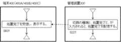
最後に、犯行の処理などが完了した後、管理装置300は、犯罪の種類などの犯行情報とともに、本件の処置完了が入力されると、処置完了を全ての端末400に配信し(ステップS221)、端末400は、処置完了を受信し、表示する(ステップS601)。 Finally, after the criminal processing and the like are completed, the
ここまでで、犯罪発生時の処理フローは終了であるが、管理装置300に記憶している犯罪情報は防犯対策に活用することができる。例えば、犯罪の発生件数などを集計し、地図上にマッピングした犯罪発生マップなどを生成し、犯罪の発生しやすい場所や特徴などを捉えることである。 Up to this point, the processing flow at the time of the occurrence of a crime is completed, but the crime information stored in the
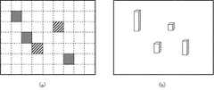
管理装置300は犯罪発生マップを生成する機能を有し、図6は管理装置300が生成した犯罪発生マップの一例である。 The
管理装置300は、図6(a)に示すように地図情報における緯度および経度により、犯罪警報件数を集計する集計範囲が設定される。管理装置300は、マッピング部316および集計部317により、例えば、範囲毎に犯罪警報件数を集計し、件数に応じた色や模様を集計範囲につけた犯罪発生マップ(図6(a))を生成したり、件数を立体棒グラフとした犯罪発生マップ(図6(b))を生成したり、する。この他にも犯罪発生マップは、多様に生成することができるので、説明は省略する。 In the
したがって、緊急連絡時に、犯罪に遭遇した端末の音声撮影データおよびその端末近傍の監視カメラの撮影データにより、犯行前後の犯人および犯行の様子を効果的に捉え、警察への連絡および情報提供を適切に行うことができる。 Therefore, at the time of emergency contact, it is possible to effectively capture the criminal before and after the criminal offense and the state of the criminal by using the voice data of the terminal that encountered the crime and the data captured by the surveillance camera in the vicinity of the terminal, and appropriately contact the police and provide information Can be done.
また、多様な犯罪発生マップを生成し、分析することで、犯罪が発生しやすい場所や犯罪の種類などを把握することができ、重点的にパトロールしたり、防犯対策を講じたり、することで、犯罪発生を抑制することができる。 In addition, by generating and analyzing various crime occurrence maps, it is possible to grasp the places where crimes are likely to occur and the types of crimes, and by patroling them intensively and taking crime prevention measures, etc. , The occurrence of crime can be suppressed.
第2の実施形態について、図を参照して説明する。 A second embodiment will be described with reference to the drawings.
緊急通報機能は、犯罪に遭遇した当人以外に、その近傍にいる人が使用してもよく、第2の実施形態は、一定の条件を満たす場合に、当該の犯罪情報を第1報の犯罪情報に関連付ける機能を、第1の実施形態の管理装置300に付加した犯罪情報管理システムである。 The emergency call function may be used by a person in the vicinity in addition to the person who encountered the crime, and the second embodiment is configured to send the crime information of the first report when certain conditions are met. It is the crime information management system which added the function linked | related with crime information to the
図7は、管理装置300に付加した処理フローを示す図であり、ステップS203の直前に付加されている。 FIG. 7 is a diagram showing a processing flow added to the
管理装置300は、ステップS201において判断した第1の犯罪情報に対し、一定の範囲内の位置情報であり、かつ、一定の時間内の受信時刻であり、かつ、子として関連付いていない第1の犯罪情報を、犯罪DB315において検索する(ステップS231)。 The
当該の犯罪情報があれば、当該の犯罪に関する関連情報と判断し、管理装置300は、当該の犯罪情報に新しい第1の犯罪情報に関連付けて記憶し、画面の表示情報を更新する(S232)。 If there is such crime information, it is determined as related information related to the crime, and the
当該の犯罪情報がなければ、新たな犯罪として、ステップS203に進む。 If there is no such crime information, the process proceeds to step S203 as a new crime.
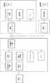
図8は第2の実施形態の画面表示の一例である。 FIG. 8 is an example of a screen display according to the second embodiment.
例えば、犯罪に遭った本人の端末を端末Aとし、その近傍でその犯罪を見た人々の端末を端末B、端末Cとする。端末Aの第1および第2の犯罪情報とともに、子として関連付けた端末B、端末Cの第1および第2の犯罪情報である関連情報334をリンク情報332に表示している。また、子として関連付けた端末B、端末Cの位置情報を、地図上にマッピングし、地図情報331にマーク335を表示してもよい。
したがって、第1の実施例の効果に加え、犯行近傍の端末の音声撮影データにより、犯行前後の犯人および犯行の様子を第1の実施例より効果的に捉えることができる。For example, the terminal of the person who encountered the crime is terminal A, and the terminals of people who saw the crime in the vicinity are terminal B and terminal C. Along with the first and second crime information of the terminal A, the
Therefore, in addition to the effects of the first embodiment, the criminals before and after the crime and the state of the crime can be captured more effectively than the first embodiment based on the audio shooting data of the terminal near the crime.
また、同一の犯罪と関連付けることで、犯罪件数の集計が容易となり、犯罪発生マップの作成を第1の実施例より容易とすることができる。 Further, by associating with the same crime, the number of crimes can be easily counted, and the creation of a crime occurrence map can be made easier than in the first embodiment.
第3の実施形態について、図を参照して説明する。 A third embodiment will be described with reference to the drawings.
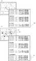
図9は、第3の実施形態を示すシステム構成図であり、一部を省略している。 FIG. 9 is a system configuration diagram showing the third embodiment, and a part thereof is omitted.
第3の実施形態は、複数の拠点や他社など、複数の管理装置300で運用し、複数の管理装置300で監視カメラの撮影データなどを共有し、表示する犯罪情報管理システムである。管理装置300A、記憶制御装置510Aおよび監視カメラ520AをA社での運用とし、管理装置300B、記憶制御装置510Bおよび監視カメラ520BをB社での運用として説明する。 The third embodiment is a crime information management system that is operated by a plurality of
図10は、管理装置300Aの管理装置300Bに対する接続に関する処理フローであり、第1または第2の実施形態において、S204に付加される処理フローである。 FIG. 10 is a process flow related to the connection of the
管理装置300Aは、自装置内のカメラDB314Aにおいて近傍の監視カメラを検索する(ステップS204)とともに、管理装置300Bに接続要求を送信する(ステップS204a)。管理装置300Bは、接続要求を受信し、接続許可と接続拒否の選択を表示する(ステップS251)。接続許可が選択されると、管理装置300Bは、管理装置300Aを接続させる(ステップS252)。接続拒否が選択されると、管理装置300Bは、管理装置300Aに接続拒否を送信し(ステップS253)、管理装置300Aは、接続拒否を表示する(ステップS261)。ここで説明した接続要求のフローは省略してもよい。 The
管理装置300Aは、自装置内のカメラDB314Aと同様に、管理装置300B内のカメラDB314Bにおいて、近傍の監視カメラ520Bの有無を検索する。当該の監視カメラ520Bがあれば、管理装置300Aは、管理装置300Bを介して、管理コードと、受信時刻とともに、当該の記憶制御装置510Bにデータ要求を送信し、撮影データを受信する。要求した撮影データを全て受信すると、管理装置300Aは、管理装置300Bとの接続を切断する。 The
図11は、第3の実施形態における犯罪DB315に記憶しているデータ構成の一例と、記憶している情報およびその関連付けのイメージを示す図である。 FIG. 11 is a diagram illustrating an example of the data configuration stored in the
管理装置300を一意とする装置コードが追加され、管理装置300は、装置コードによりB社からの情報であることを判断し、関連付けている。 A device code that makes the
図12は、第3の実施形態における表示画面の一例である。 FIG. 12 is an example of a display screen in the third embodiment.
図12(a)は、リンク情報332に、監視カメラ520Bが撮影した撮影データであるB社情報336へのリンク情報を表示している。 In FIG. 12A, link
図12(b)は、リンク情報332に、更に、管理装置400Bが受信したB社関連情報337へのリンク情報を表示している。 FIG. 12B displays link information to the company B related
したがって、第1および第2の実施例の効果に加え、他社からの音声撮影データにより、犯行前後の犯人および犯行の様子を第1および第2の実施例より効果的に捉えることができる。 Therefore, in addition to the effects of the first and second embodiments, the criminals before and after the crime and the state of the crime can be captured more effectively than the first and second embodiments based on the audio shooting data from other companies.
本システムは、犯罪について説明してきたが、犯罪以外に、災害や交通事故などにも適用でき、例えば、救助に向かうまでの間に災害や交通事故の状況を把握することができる。 Although this system has been described for crimes, it can also be applied to disasters and traffic accidents in addition to crimes. For example, it is possible to grasp the situation of disasters and traffic accidents before heading for rescue.
100 基地局
200 ネットワーク
300、300A、300B 犯罪情報管理装置
310 犯罪情報管理装置本体
311 制御部
312 地図情報DB
313 利用者情報DB
314 監視カメラ情報DB
315 犯罪情報管理DB
320 入力装置
330 表示装置
340 音声出力装置
400A 通報端末
400B ユーザ端末
400C 警備端末
510、510A、510B 記憶制御装置
520、520A、520B 監視カメラDESCRIPTION OF
313 User information DB
314 Surveillance camera information DB
315 Crime Information Management DB
320
Claims (10)
Translated fromJapanese前記携帯通信端末は、犯罪情報を送信する操作がなされると、自端末の位置情報である端末位置情報と、自端末を一意に示す端末コードと、を取得し、少なくとも、前記端末位置情報と、前記端末コードと、からなる第1の犯罪情報を、前記基地局を介し、前記犯罪情報管理装置に送信し、犯罪が発生したことを示す犯罪警報を前記犯罪情報管理装置から受信し、
前記犯罪情報管理装置は、前記第1の犯罪情報を受信すると、前記第1の犯罪情報を一意とする管理コードを生成し、前記第1の犯罪情報を受信した受信時刻とともに記憶し、前記犯罪警報を前記携帯通信端末に送信し、前記端末位置情報の近傍に設置された前記監視カメラの前記撮影データを記憶している前記記憶制御装置を検索し、当該の記憶制御装置に第1の検索条件とともに撮影データの要求を送信し、前記撮影データの要求に対する返信である当該の前記撮影データを受信し、当該の前記撮影データを前記管理コードに関連付けて記憶し、
前記記憶制御装置は、前記撮影データの要求を受信すると、前記第1の検索条件により決定する第2の検索条件を満たす前記撮影データを検索し、当該の前記撮影データを前記犯罪情報管理装置に送信する、
ことを特徴とする犯罪情報管理装置および犯罪情報管理システム。Storage control for storing a mobile communication terminal having a crime information transmission function for transmitting crime information, a base station for controlling communication of the mobile communication terminal, a monitoring camera, and shooting data that is a moving image or an image shot by the monitoring camera A crime information management system comprising a device, and a crime information management device communicating with the portable communication terminal and the storage control device,
When the mobile communication terminal is operated to transmit crime information, the mobile communication terminal acquires terminal position information that is position information of the own terminal and a terminal code that uniquely indicates the own terminal, and at least the terminal position information and , Transmitting the first crime information consisting of the terminal code to the crime information management device via the base station, and receiving a crime warning indicating that a crime has occurred from the crime information management device,
When the crime information management device receives the first crime information, the crime information management device generates a management code that uniquely identifies the first crime information, stores the first crime information together with a reception time when the crime information is received, An alarm is transmitted to the mobile communication terminal, the storage control device storing the imaging data of the monitoring camera installed in the vicinity of the terminal position information is searched, and the first search is performed in the storage control device. Sending a request for shooting data together with a condition, receiving the shooting data in response to the request for shooting data, storing the shooting data in association with the management code;
When the storage control device receives the shooting data request, the storage control device searches the shooting data satisfying a second search condition determined by the first search condition, and stores the shooting data in the crime information management device. Send,
Crime information management device and crime information management system characterized by the above.
前記犯罪情報管理装置は、前記第2の犯罪情報を受信すると、前記第2の犯罪情報の前記受信時刻を記憶し、前記第2の犯罪情報における前記端末コードと一致し、かつ、関連付条件を満たす、記憶している前記第1の犯罪情報に、前記第2の犯罪情報を関連付ける
ことを特徴とする請求項1に記載の犯罪情報管理装置および犯罪情報管理システム。The portable communication terminal is a recording data of a predetermined time acquired by an attached microphone, a recording of a predetermined time acquired by an attached camera or a shooting data of a predetermined number of images, or a combination thereof, and the terminal A second crime information comprising a code, and a function of transmitting to the crime information management device,
When the crime information management device receives the second crime information, the crime information management device stores the reception time of the second crime information, matches the terminal code in the second crime information, and an associated condition The crime information management apparatus and the crime information management system according to claim 1, wherein the second crime information is associated with the stored first crime information that satisfies the condition.
ことを特徴とする請求項2に記載の犯罪情報管理装置および犯罪情報管理システム。The association condition is that the reception time of the first crime information is latest within a predetermined time with respect to the reception time of the second crime information. Item 3. The crime information management device and crime information management system according to item 2.
ことを特徴とする請求項1及至請求項3のいずれかに記載の犯罪情報管理装置および犯罪情報管理システム。The crime information management has a function of counting the stored terminal location information as the number of crime occurrences with a certain area as a unit of aggregation, and generating a crime occurrence map that combines the number of crime occurrences on a map,
The crime information management apparatus and crime information management system according to any one of claims 1 to 3.
ことを特徴とする請求項1及至請求項4のいずれかに記載の犯罪情報管理装置および犯罪情報管理システム。5. The crime alarm according to any one of claims 1 to 4, wherein the crime alarm includes at least map information obtained by combining the terminal position information indicating a transmission location of the first crime information on a map. Described crime information management device and crime information management system.
ことを特徴とする請求項1及至請求項5のいずれかに記載の犯罪情報管理装置および犯罪情報管理システム。2. The crime alarm includes at least map information obtained by combining the terminal location information of the communication terminal that has received the crime alarm on a map at the time of receiving the crime alarm. The crime information management apparatus and crime information management system according to claim 5.
ことを特徴とする請求項1及至請求項6のいずれかに記載の犯罪情報管理装置および犯罪情報管理システム。The crime information management apparatus and crime information management system according to any one of claims 1 to 6, wherein the portable communication terminal has a GPS function and acquires the terminal position information by the GPS function.
前記携帯通信端末が前記電波を受信し、前記犯罪情報管理装置に送信し、
前記犯罪情報管理装置が前記カメラ情報を受信し、前記カメラ情報により前記監視カメラの設置場所を特定し、前記端末位置情報とする
ことを特徴とする請求項1及至請求項6のいずれかに記載の犯罪情報管理装置および犯罪情報管理システム。The surveillance camera transmits radio waves including camera information that can identify the surveillance camera,
The mobile communication terminal receives the radio wave, transmits it to the crime information management device,
The said crime information management apparatus receives the said camera information, specifies the installation location of the said surveillance camera by the said camera information, and uses it as the said terminal position information, The any one of Claim 1 to 6 characterized by the above-mentioned. Crime information management device and crime information management system.
前記携帯通信端末が、所定の操作により、犯罪発生を示す緊急通報を前記基地局に送信し、
前記基地局が前記緊急通報を受信し、前記携帯通信端末の位置情報である基地局位置情報を取得し、前記犯罪情報管理装置に送信し、
前記犯罪情報管理装置が前記基地局位置情報を受信し、前記基地局位置情報を前記端末位置情報とする
ことを特徴とする請求項1及至請求項6のいずれかに記載の犯罪情報管理装置および犯罪情報管理システム。The base station has a function of acquiring location information of the mobile communication terminal,
The mobile communication terminal transmits an emergency call indicating the occurrence of a crime to the base station by a predetermined operation,
The base station receives the emergency call, acquires base station location information that is location information of the mobile communication terminal, and transmits it to the crime information management device,
The crime information management device according to any one of claims 1 to 6, wherein the crime information management device receives the base station location information and uses the base station location information as the terminal location information. Crime information management system.
ことを特徴とする請求項1及請求項9のいずれかに記載の犯罪情報管理装置および犯罪情報管理システム。The first search condition or the second search condition includes at least a predetermined time before and after the reception time of the first crime information as a base point. The crime information management device and crime information management system according to claim 9.
Priority Applications (1)
| Application Number | Priority Date | Filing Date | Title |
|---|---|---|---|
| JP2012187585AJP2014044641A (en) | 2012-08-28 | 2012-08-28 | Crime information management device and crime information management system |
Applications Claiming Priority (1)
| Application Number | Priority Date | Filing Date | Title |
|---|---|---|---|
| JP2012187585AJP2014044641A (en) | 2012-08-28 | 2012-08-28 | Crime information management device and crime information management system |
Publications (1)
| Publication Number | Publication Date |
|---|---|
| JP2014044641Atrue JP2014044641A (en) | 2014-03-13 |
Family
ID=50395845
Family Applications (1)
| Application Number | Title | Priority Date | Filing Date |
|---|---|---|---|
| JP2012187585APendingJP2014044641A (en) | 2012-08-28 | 2012-08-28 | Crime information management device and crime information management system |
Country Status (1)
| Country | Link |
|---|---|
| JP (1) | JP2014044641A (en) |
Cited By (6)
| Publication number | Priority date | Publication date | Assignee | Title |
|---|---|---|---|---|
| JP2016103231A (en)* | 2014-11-28 | 2016-06-02 | 京セラドキュメントソリューションズ株式会社 | Tracking system and tracking program |
| JP2018061215A (en)* | 2016-10-07 | 2018-04-12 | パナソニックIpマネジメント株式会社 | Monitoring system and monitoring method |
| JP2019220853A (en)* | 2018-06-20 | 2019-12-26 | 株式会社チャオ | Incoming linked camera system |
| JP2020021080A (en)* | 2014-12-26 | 2020-02-06 | マクセル株式会社 | Lighting equipment |
| JP2020072416A (en)* | 2018-11-01 | 2020-05-07 | トヨタ自動車株式会社 | Patrol system |
| CN112201021A (en)* | 2020-10-10 | 2021-01-08 | 合肥远康信息技术有限公司 | Intelligent 110 networking comprehensive alarm platform central control system |
- 2012
- 2012-08-28JPJP2012187585Apatent/JP2014044641A/enactivePending
Cited By (8)
| Publication number | Priority date | Publication date | Assignee | Title |
|---|---|---|---|---|
| JP2016103231A (en)* | 2014-11-28 | 2016-06-02 | 京セラドキュメントソリューションズ株式会社 | Tracking system and tracking program |
| JP2020021080A (en)* | 2014-12-26 | 2020-02-06 | マクセル株式会社 | Lighting equipment |
| US10997846B2 (en) | 2014-12-26 | 2021-05-04 | Maxell, Ltd. | Lighting apparatus |
| JP2018061215A (en)* | 2016-10-07 | 2018-04-12 | パナソニックIpマネジメント株式会社 | Monitoring system and monitoring method |
| JP2019220853A (en)* | 2018-06-20 | 2019-12-26 | 株式会社チャオ | Incoming linked camera system |
| JP2020072416A (en)* | 2018-11-01 | 2020-05-07 | トヨタ自動車株式会社 | Patrol system |
| JP7173436B2 (en) | 2018-11-01 | 2022-11-16 | トヨタ自動車株式会社 | patrol system |
| CN112201021A (en)* | 2020-10-10 | 2021-01-08 | 合肥远康信息技术有限公司 | Intelligent 110 networking comprehensive alarm platform central control system |
Similar Documents
| Publication | Publication Date | Title |
|---|---|---|
| US20250203007A1 (en) | Unmanned aerial vehicle emergency dispatch and diagnostics data apparatus, systems and methods | |
| US11902871B2 (en) | Systems and methods for identifying and activating emergency response assets | |
| US12323557B2 (en) | Apparatus and method for emergency dispatch | |
| US11665523B2 (en) | Systems and methods for emergency communications amongst groups of devices based on shared data | |
| US20220014895A1 (en) | Spatiotemporal analysis for emergency response | |
| US20240406699A1 (en) | Systems and methods for emergency data integration | |
| US11749094B2 (en) | Apparatus, systems and methods for providing alarm and sensor data to emergency networks | |
| US10349227B2 (en) | Personal safety system | |
| EP3033742B1 (en) | System and method for video/audio and event dispatch using positioning system | |
| CA3162430A1 (en) | Systems and methods for delivering and supporting digital requests for emergency service | |
| US9767677B1 (en) | Data driven emergency notification application and system | |
| JP5094370B2 (en) | Rescue request system | |
| JP5715775B2 (en) | Image monitoring system and image monitoring method | |
| CN107633666A (en) | Alarm method, alarm processing method, electronic device and computer storage medium | |
| JP2014044641A (en) | Crime information management device and crime information management system | |
| KR102368523B1 (en) | Method for providing emergency reporting service using physical buttion | |
| US20200236525A1 (en) | Data driven emergency notification application and system | |
| US20240396625A1 (en) | Apparatus, systems and methods for providing emergency assistance communication and data to emergency networks using a satellite communication system | |
| KR102046807B1 (en) | System for transmission of emergency rescue location | |
| TWI606426B (en) | System and method for personal circumference surrounding safety notification | |
| JP6350246B2 (en) | Tracking system and tracking program |