JP2014044445A - Catadioptric projection objective lens having intermediate image - Google Patents
Catadioptric projection objective lens having intermediate imageDownload PDFInfo
- Publication number
- JP2014044445A JP2014044445AJP2013248395AJP2013248395AJP2014044445AJP 2014044445 AJP2014044445 AJP 2014044445AJP 2013248395 AJP2013248395 AJP 2013248395AJP 2013248395 AJP2013248395 AJP 2013248395AJP 2014044445 AJP2014044445 AJP 2014044445A
- Authority
- JP
- Japan
- Prior art keywords
- image
- objective
- lens
- projection objective
- concave mirror
- Prior art date
- Legal status (The legal status is an assumption and is not a legal conclusion. Google has not performed a legal analysis and makes no representation as to the accuracy of the status listed.)
- Pending
Links
- 230000005855radiationEffects0.000claimsabstractdescription57
- 238000003384imaging methodMethods0.000claimsabstractdescription38
- 238000005452bendingMethods0.000claimsabstractdescription21
- 230000003287optical effectEffects0.000claimsdescription124
- 238000011144upstream manufacturingMethods0.000claimsdescription28
- 238000007654immersionMethods0.000claimsdescription23
- 230000002093peripheral effectEffects0.000claimsdescription19
- 239000000758substrateSubstances0.000claimsdescription13
- 101100385324Arabidopsis thaliana CRA1 geneProteins0.000claimsdescription10
- 238000000034methodMethods0.000claimsdescription10
- 238000004519manufacturing processMethods0.000claimsdescription9
- 230000004323axial lengthEffects0.000claimsdescription8
- 238000005286illuminationMethods0.000claimsdescription8
- 230000010287polarizationEffects0.000claimsdescription6
- WUKWITHWXAAZEY-UHFFFAOYSA-Lcalcium difluorideChemical compound[F-].[F-].[Ca+2]WUKWITHWXAAZEY-UHFFFAOYSA-L0.000claimsdescription4
- 229910001634calcium fluorideInorganic materials0.000claimsdescription4
- 239000004065semiconductorSubstances0.000claimsdescription4
- 230000008878couplingEffects0.000claimsdescription2
- 238000010168coupling processMethods0.000claimsdescription2
- 238000005859coupling reactionMethods0.000claimsdescription2
- 238000001393microlithographyMethods0.000claimsdescription2
- 230000007704transitionEffects0.000claimsdescription2
- 238000013461designMethods0.000abstractdescription35
- 238000012937correctionMethods0.000description42
- 230000004075alterationEffects0.000description21
- 230000000694effectsEffects0.000description17
- 239000000463materialSubstances0.000description10
- 210000001747pupilAnatomy0.000description9
- 238000010586diagramMethods0.000description8
- 239000007788liquidSubstances0.000description7
- 230000014509gene expressionEffects0.000description6
- 238000000671immersion lithographyMethods0.000description6
- 238000001459lithographyMethods0.000description4
- 230000008901benefitEffects0.000description3
- 230000005540biological transmissionEffects0.000description3
- 230000007423decreaseEffects0.000description3
- 229920002120photoresistant polymerPolymers0.000description3
- 230000008569processEffects0.000description3
- 230000009467reductionEffects0.000description3
- 238000001035dryingMethods0.000description2
- 238000009434installationMethods0.000description2
- 238000000691measurement methodMethods0.000description2
- 239000010702perfluoropolyetherSubstances0.000description2
- 238000000206photolithographyMethods0.000description2
- 238000012935AveragingMethods0.000description1
- 229920001774PerfluoroetherPolymers0.000description1
- VYPSYNLAJGMNEJ-UHFFFAOYSA-NSilicium dioxideChemical compoundO=[Si]=OVYPSYNLAJGMNEJ-UHFFFAOYSA-N0.000description1
- 230000009471actionEffects0.000description1
- 230000001154acute effectEffects0.000description1
- 230000002411adverseEffects0.000description1
- 238000013459approachMethods0.000description1
- 230000015572biosynthetic processEffects0.000description1
- 238000004364calculation methodMethods0.000description1
- 230000008859changeEffects0.000description1
- 238000005056compactionMethods0.000description1
- 238000007596consolidation processMethods0.000description1
- 230000008094contradictory effectEffects0.000description1
- 239000013078crystalSubstances0.000description1
- 230000007547defectEffects0.000description1
- 238000009792diffusion processMethods0.000description1
- 239000006185dispersionSubstances0.000description1
- 238000009826distributionMethods0.000description1
- 238000005516engineering processMethods0.000description1
- 210000003128headAnatomy0.000description1
- 239000012535impuritySubstances0.000description1
- 239000004973liquid crystal related substanceSubstances0.000description1
- 238000005259measurementMethods0.000description1
- 230000007246mechanismEffects0.000description1
- 230000005499meniscusEffects0.000description1
- 238000012986modificationMethods0.000description1
- 230000004048modificationEffects0.000description1
- 238000005457optimizationMethods0.000description1
- UJMWVICAENGCRF-UHFFFAOYSA-Noxygen difluorideChemical compoundFOFUJMWVICAENGCRF-UHFFFAOYSA-N0.000description1
- 230000008092positive effectEffects0.000description1
- 238000012797qualificationMethods0.000description1
- 238000000926separation methodMethods0.000description1
- 238000007493shaping processMethods0.000description1
- 239000007787solidSubstances0.000description1
- 229910021642ultra pure waterInorganic materials0.000description1
- 239000012498ultrapure waterSubstances0.000description1
Images


Classifications
- G—PHYSICS
- G03—PHOTOGRAPHY; CINEMATOGRAPHY; ANALOGOUS TECHNIQUES USING WAVES OTHER THAN OPTICAL WAVES; ELECTROGRAPHY; HOLOGRAPHY
- G03F—PHOTOMECHANICAL PRODUCTION OF TEXTURED OR PATTERNED SURFACES, e.g. FOR PRINTING, FOR PROCESSING OF SEMICONDUCTOR DEVICES; MATERIALS THEREFOR; ORIGINALS THEREFOR; APPARATUS SPECIALLY ADAPTED THEREFOR
- G03F7/00—Photomechanical, e.g. photolithographic, production of textured or patterned surfaces, e.g. printing surfaces; Materials therefor, e.g. comprising photoresists; Apparatus specially adapted therefor
- G03F7/70—Microphotolithographic exposure; Apparatus therefor
- G03F7/70058—Mask illumination systems
- G—PHYSICS
- G02—OPTICS
- G02B—OPTICAL ELEMENTS, SYSTEMS OR APPARATUS
- G02B17/00—Systems with reflecting surfaces, with or without refracting elements
- G02B17/08—Catadioptric systems
- G—PHYSICS
- G02—OPTICS
- G02B—OPTICAL ELEMENTS, SYSTEMS OR APPARATUS
- G02B17/00—Systems with reflecting surfaces, with or without refracting elements
- G02B17/08—Catadioptric systems
- G02B17/0804—Catadioptric systems using two curved mirrors
- G—PHYSICS
- G02—OPTICS
- G02B—OPTICAL ELEMENTS, SYSTEMS OR APPARATUS
- G02B17/00—Systems with reflecting surfaces, with or without refracting elements
- G02B17/02—Catoptric systems, e.g. image erecting and reversing system
- G02B17/06—Catoptric systems, e.g. image erecting and reversing system using mirrors only, i.e. having only one curved mirror
- G—PHYSICS
- G02—OPTICS
- G02B—OPTICAL ELEMENTS, SYSTEMS OR APPARATUS
- G02B17/00—Systems with reflecting surfaces, with or without refracting elements
- G02B17/08—Catadioptric systems
- G02B17/0892—Catadioptric systems specially adapted for the UV
- G—PHYSICS
- G03—PHOTOGRAPHY; CINEMATOGRAPHY; ANALOGOUS TECHNIQUES USING WAVES OTHER THAN OPTICAL WAVES; ELECTROGRAPHY; HOLOGRAPHY
- G03F—PHOTOMECHANICAL PRODUCTION OF TEXTURED OR PATTERNED SURFACES, e.g. FOR PRINTING, FOR PROCESSING OF SEMICONDUCTOR DEVICES; MATERIALS THEREFOR; ORIGINALS THEREFOR; APPARATUS SPECIALLY ADAPTED THEREFOR
- G03F7/00—Photomechanical, e.g. photolithographic, production of textured or patterned surfaces, e.g. printing surfaces; Materials therefor, e.g. comprising photoresists; Apparatus specially adapted therefor
- G03F7/70—Microphotolithographic exposure; Apparatus therefor
- G03F7/70058—Mask illumination systems
- G03F7/7015—Details of optical elements
- G—PHYSICS
- G03—PHOTOGRAPHY; CINEMATOGRAPHY; ANALOGOUS TECHNIQUES USING WAVES OTHER THAN OPTICAL WAVES; ELECTROGRAPHY; HOLOGRAPHY
- G03F—PHOTOMECHANICAL PRODUCTION OF TEXTURED OR PATTERNED SURFACES, e.g. FOR PRINTING, FOR PROCESSING OF SEMICONDUCTOR DEVICES; MATERIALS THEREFOR; ORIGINALS THEREFOR; APPARATUS SPECIALLY ADAPTED THEREFOR
- G03F7/00—Photomechanical, e.g. photolithographic, production of textured or patterned surfaces, e.g. printing surfaces; Materials therefor, e.g. comprising photoresists; Apparatus specially adapted therefor
- G03F7/70—Microphotolithographic exposure; Apparatus therefor
- G03F7/70216—Mask projection systems
- G03F7/70225—Optical aspects of catadioptric systems, i.e. comprising reflective and refractive elements
- G—PHYSICS
- G03—PHOTOGRAPHY; CINEMATOGRAPHY; ANALOGOUS TECHNIQUES USING WAVES OTHER THAN OPTICAL WAVES; ELECTROGRAPHY; HOLOGRAPHY
- G03F—PHOTOMECHANICAL PRODUCTION OF TEXTURED OR PATTERNED SURFACES, e.g. FOR PRINTING, FOR PROCESSING OF SEMICONDUCTOR DEVICES; MATERIALS THEREFOR; ORIGINALS THEREFOR; APPARATUS SPECIALLY ADAPTED THEREFOR
- G03F7/00—Photomechanical, e.g. photolithographic, production of textured or patterned surfaces, e.g. printing surfaces; Materials therefor, e.g. comprising photoresists; Apparatus specially adapted therefor
- G03F7/70—Microphotolithographic exposure; Apparatus therefor
- G03F7/70216—Mask projection systems
- G03F7/70275—Multiple projection paths, e.g. array of projection systems, microlens projection systems or tandem projection systems
Landscapes
- Physics & Mathematics (AREA)
- General Physics & Mathematics (AREA)
- Optics & Photonics (AREA)
- Lenses (AREA)
- Exposure And Positioning Against Photoresist Photosensitive Materials (AREA)
- Exposure Of Semiconductors, Excluding Electron Or Ion Beam Exposure (AREA)
Abstract
Description
Translated fromJapanese本発明は、自身の物体平面上に配置されるパターンを自身の像平面上に結像させるカタジオプトリック投影対物レンズに関する。 The present invention relates to a catadioptric projection objective lens that forms an image of a pattern arranged on its own object plane on its own image plane.
このような投影対物レンズは、半導体構成品およびその他の微細構造素子を製造するマイクロリソグラフィー投影露光システムに用いられる。これらは、以下の本文中においてフォトマスクまたはレチクルと呼ばれるパターンを、一般にマスクまたはレチクルの形態で、感光層により被覆される物体上に非常に高い解像度で、かつある縮尺で投影するのに用いられる。 Such projection objectives are used in microlithographic projection exposure systems that produce semiconductor components and other microstructured elements. These are used in the following text to project a pattern, called a photomask or reticle, generally in the form of a mask or reticle, onto an object covered by a photosensitive layer, at a very high resolution and to a certain scale. .
この場合に、さらに一層微細な構造を製造するためには、一方では投影対物レンズの像側の開口数(NA)を増大させ、かつ他方ではさらに一層短い波長、好ましくは約260nm未満、たとえば248nm、193nmまたは157nmの波長の紫外光を用いることが必要である。 In this case, in order to produce even finer structures, on the one hand the image side numerical aperture (NA) of the projection objective is increased, and on the other hand even shorter wavelengths, preferably less than about 260 nm, for example 248 nm. It is necessary to use ultraviolet light with a wavelength of 193 nm or 157 nm.
これまでは、主に純屈折性の投影対物レンズが光リソグラフィーに用いられてきた。これらは、折り曲げられない単一の光軸のみを有する機械的に比較的単純な軸対称の設計により弁別される。さらにまた、光軸に対して対称な物体フィールドを用いて、補正対象となる光透過レベルを最小限にするとともに、対物レンズの調節を簡単にすることができる。 Until now, purely refractive projection objectives have been used for photolithography. These are distinguished by a mechanically relatively simple axisymmetric design having only a single optical axis that cannot be folded. Furthermore, by using an object field that is symmetric with respect to the optical axis, it is possible to minimize the light transmission level to be corrected and simplify the adjustment of the objective lens.
しかしながら、屈折性の設計形態は、第一に、色補正とペッツヴァルの和の補正(像面湾曲)との2つの基本的な結像誤差を特徴とする。 However, the refractive design form is primarily characterized by two basic imaging errors: color correction and Petzval sum correction (field curvature).
少なくとも1個のカタジオプトリック対物レンズ部分と凹状の鏡または凹面鏡とを有するカタジオプトリック設計を用いて、ペッツヴァルの条件の補正を簡単にし、かつ色補正の能力を得ることができる。この場合に、ペッツヴァルの補正は、凹面鏡の曲率と該凹面鏡に近接する負レンズとによって達成される一方で、色補正は、凹面鏡の上流の負レンズの屈折力(CHLの補正)と凹面鏡に対する絞りの位置(CHV)とによって達成される。 A catadioptric design with at least one catadioptric objective part and a concave mirror or concave mirror can be used to simplify the correction of Petzval conditions and to obtain color correction capabilities. In this case, Petzval's correction is achieved by the curvature of the concave mirror and the negative lens close to the concave mirror, while color correction is the refractive power of the negative lens upstream of the concave mirror (CHL correction) and the aperture to the concave mirror. Position (CHV).
しかし、ビーム分割を有するカタジオプトリック設計のひとつの欠点は、軸外物体フィールド、すなわちより高い光伝導値(幾何学的ビーム分割を用いるシステムの場合)または一般に偏光の問題を引き起こす物理的なビーム分割素子のいずれかとともに機能することが必要であるというところにある。本明細書において用いられるところの「光伝導値」という用語は、本願の出願書類においては、像フィールド直径と像側開口数との積として定義されるラグランジュの光学的不変量またはエタンデュを指す。 However, one drawback of catadioptric designs with beam splitting is that they are off-axis object fields, ie higher photoconductivity values (for systems using geometric beam splitting) or physical problems that generally cause polarization problems. It is necessary to work with any of the beam splitting elements. As used herein, the term “photoconductive value” refers to the Lagrangian optical invariant or etendue defined in the application of this application as the product of the image field diameter and the image-side numerical aperture.
軸外カタジオプトリックシステムの場合、すなわち幾何学的ビーム分割を有するシステムの場合は、光学設計の要件は、次のように公式化される:(1)光透過レベルを最大限に低下させること、(2)折曲(ビーム偏向)の幾何学的形状を、そのための取付け技術が開発可能になるように設計すること、および(3)カタジオプトリック鏡群内において共同的に効果的な補正、特にペッツヴァルの和と色収差との補正を達成しうること。 In the case of off-axis catadioptric systems, i.e. systems with geometric beam splitting, the optical design requirements are formulated as follows: (1) maximizing the light transmission level , (2) designing the bending (beam deflection) geometry so that mounting techniques for it can be developed, and (3) collaboratively effective within the catadioptric mirror group Correction, especially correction of Petzval sum and chromatic aberration can be achieved.
幾何学的光伝導レベル(エタンデュ)を低く保つためには、折曲が、原則として、低いNAの領域内、すなわちたとえば物体の近傍または中間実像に近接する位置において行なわれる設計にしなければならない。 In order to keep the geometric photoconductivity level (etendue) low, the bending must in principle be performed in the region of low NA, for example in the vicinity of the object or close to the intermediate real image.
しかしながら、開口数が増大すると、物体側開口数もまた増大し、よって第1の折曲鏡とレチクルとの間における距離が増加して、光透過レベルが高まるようになる。さらにまた、凹状の鏡の直径と折曲鏡の大きさとが増大する。このことは、物理的な配設空間の問題を招きうる。 However, as the numerical aperture increases, the object side numerical aperture also increases, thus increasing the distance between the first folding mirror and the reticle and increasing the light transmission level. Furthermore, the diameter of the concave mirror and the size of the folding mirror increase. This can lead to physical space issues.
これらの問題は、まず第1に、第1の中継システムによって、レチクルを中間像上に結像させるとともに、第1の折曲を前記中間像の領域内において行なうことによって克服されうる。このようなカタジオプトリックシステムは、欧州特許第1191378A1号に開示されている。このシステムは、屈折性の中継システムと、凹面鏡を有する後続のカタジオプトリック対物レンズ部分とを有する。光は、物体平面から、第1の中間像に近接して配置される折曲鏡(偏向鏡)に入射するとともに、前記折曲鏡から凹面鏡に、そして前記凹面鏡から屈折性対物レンズ部分に入射して、第2の中間実像が第2の偏向鏡に近接して生じしめられ、前記屈折性対物レンズ部分は、この第2の中間像を像平面(ウェーハ)上に結像させる。屈折性(R)、反射屈折性(C)および屈折性(R)の結像サブシステムを前記の順序で有する連結システムは、以下では「R−C−R」形システムと呼ばれる。 These problems can first be overcome by forming a reticle on the intermediate image by the first relay system and performing a first fold in the region of the intermediate image. Such a catadioptric system is disclosed in EP 1 191 378 A1. This system has a refractive relay system and a subsequent catadioptric objective part with a concave mirror. Light is incident on the bending mirror (deflecting mirror) arranged close to the first intermediate image from the object plane, and is incident on the concave mirror from the folding mirror and on the refractive objective lens portion from the concave mirror. Then, a second intermediate real image is generated in the vicinity of the second deflecting mirror, and the refractive objective lens part forms the second intermediate image on the image plane (wafer). A coupling system having the refractive (R), catadioptric (C) and refractive (R) imaging subsystems in the above order is referred to hereinafter as an “RCR” type system.
同様の折曲形状を有するR−C−R形システムは、国際特許第2004/019128A号、国際特許第03/036361A1号および米国特許第2002/019946A1号に開示されている。米国特許出願第2004/0233405A1号には、第1の折曲鏡が光学的に凹面鏡の下流に配置されて、前記凹面鏡から到来する放射を像平面の方へと偏向させる、対物レンズを含む異なる折曲形状を有するR−C−R形投影対物レンズが開示されている。 An R-C-R type system having a similar folded shape is disclosed in International Patent No. 2004 / 019128A, International Patent No. 03 / 036361A1 and US Patent No. 2002 / 019946A1. US Patent Application No. 2004/0233405 A1 includes a first folding mirror optically disposed downstream of a concave mirror, including an objective lens that deflects radiation coming from the concave mirror toward the image plane. An R-C-R type projection objective having a bent shape is disclosed.
2つの中間実像を有するまた他のカタジオプトリックシステムは、日本国特許公開第2002−372668号および米国特許第5,636,066号に開示されている。国際特許第02/082159A1号および国際特許第01/04682号には、1つを超える個数の中間像を有するさらに他のカタジオプトリックシステムが開示されている。 Another catadioptric system having two intermediate real images is disclosed in Japanese Patent Publication No. 2002-372668 and US Pat. No. 5,636,066. WO 02/082159 A1 and WO 01/04682 disclose yet another catadioptric system having more than one intermediate image.
本発明の1つの目的は、最適な寸法を有するコンパクトな設計の、非常に高い解像度を達成することを可能とするカタジオプトリック投影対物レンズを提供することにある。さらに他の目的は、ペッツヴァルの和と色収差との補正を良好な製造条件とともに可能にすることにある。 One object of the present invention is to provide a catadioptric projection objective that makes it possible to achieve very high resolution in a compact design with optimal dimensions. Yet another object is to enable correction of Petzval sum and chromatic aberration with good manufacturing conditions.
前記およびその他の目的を達成する方法として、本発明は、1つの態様によれば、自身の物体平面上に配置されるパターンを自身の像平面上に結像させるカタジオプトリック投影対物レンズにおいて:物体フィールドを結像させて第1の中間実像を形成する第1の対物レンズ部分と;前記第1の対物レンズ部分から到来する放射を用いて第2の中間実像を生じしめる第2の対物レンズ部分と;前記第2の中間実像を前記像平面上に結像させる第3の対物レンズ部分とを有し、前記第2の対物レンズ部分は、凹面鏡を有するカタジオプトリック対物レンズ部分であり;前記物体平面から到来する放射を前記凹面鏡の方向に偏向させる第1の折曲鏡と、前記凹面鏡から到来する放射を前記像平面の方向に偏向させる第2の折曲鏡とが設けられ;正の屈折力を有するフィールドレンズが、前記第1の中間像と前記凹面鏡との間において、前記第1の中間像のフィールドに近接する領域内に配置されるカタジオプトリック投影対物レンズを提供する。 According to one aspect, the present invention provides a method for achieving the above and other objects in a catadioptric projection objective that images a pattern disposed on its object plane onto its image plane. A first objective lens part for imaging the object field to form a first intermediate real image; and a second objective for producing a second intermediate real image using radiation coming from the first objective lens part A third objective lens portion for forming the second intermediate real image on the image plane, and the second objective lens portion is a catadioptric objective lens portion having a concave mirror. Yes; a first folding mirror for deflecting radiation coming from the object plane in the direction of the concave mirror and a second folding mirror for deflecting radiation coming from the concave mirror in the direction of the image plane are provided ; Positive A field lens having a refractive power in between the first intermediate image and the concave mirror, provides a catadioptric projection objective which is arranged in the region close to the field of the first intermediate image.
また他の態様によれば、正の屈折力を有するフィールドレンズは、幾何学的に、前記第1の折曲鏡と前記凹面鏡との間において、前記第1の中間像のフィールドに近接する領域内に配置される。この位置は、前記第1の中間像が光学的に上流、すなわち光の伝播方向に前記フィールドレンズの前において創出される場合は、光学的に前記第1の中間像と前記凹面鏡との間にある。第1の中間像は、さらにまた、光学的に下流、すなわち前記フィールドレンズの後に配置され得、または部分的に前記フィールドレンズ内に延在しうる。 According to another aspect, the field lens having a positive refractive power is geometrically located between the first folding mirror and the concave mirror and in the region close to the field of the first intermediate image. Placed inside. This position is optically between the first intermediate image and the concave mirror if the first intermediate image is created optically upstream, ie in front of the field lens in the direction of light propagation. is there. The first intermediate image may also be placed optically downstream, i.e. after the field lens, or partially extend into the field lens.
非常に高い解像度を達成するために必要とされる開口数の増大は、従来技術のシステムにおいては、往々にして、好ましい絞り位置の領域内に配置される光学素子の直径の重大な増加を招く。本発明は、こうした効果を打ち消すものである。 The increase in the numerical aperture required to achieve very high resolution often results in a significant increase in the diameter of the optical element located in the region of the preferred aperture position in prior art systems. . The present invention counteracts these effects.
「フィールドレンズ」という表現は、個別のレンズまたは少なくとも2個の個別のレンズを有するレンズ群を表す。この表現は、レンズの機能が基本的に2個以上のレンズ(レンズの分割)によっても果たされうるという事実を考慮に入れたものである。このフィールドレンズの屈折力は、フィールドの近傍、すなわち光学的にフィールド平面に近接する位置において配置される。このフィールド平面のフィールド近傍の領域は、特に、結像の主光線高さが周辺光線高さと比べて大きくなることによって弁別される。この場合に、周辺光線高さは、光軸に最も近い物体フィールドの最内側点から開口絞りの縁部へと至る周辺光線の光線高さである一方で、主光線(プリンシパルレイ)は、光軸に対して平行または鋭角をなす物体フィールドの最外側フィールド点から発するとともにシステム絞りの領域内、すなわち開口絞りの取付けに適する絞り位置において光軸と交差する。これにより、周辺光線高さと主光線高さとの間における比は、フィールド近傍の領域内において1未満となる。 The expression “field lens” represents an individual lens or a group of lenses having at least two individual lenses. This representation takes into account the fact that the function of a lens can basically be fulfilled by more than one lens (lens splitting). The refractive power of the field lens is arranged in the vicinity of the field, that is, at a position optically close to the field plane. The region in the vicinity of the field plane is distinguished by the fact that the principal ray height for image formation is larger than the height of the peripheral ray. In this case, the marginal ray height is the ray height of the marginal ray from the innermost point of the object field closest to the optical axis to the edge of the aperture stop, while the principal ray (principal ray) It originates from the outermost field point of the object field that is parallel or acute with respect to the axis and intersects the optical axis in the region of the system stop, i.e. at the stop position suitable for mounting the aperture stop. Thereby, the ratio between the peripheral ray height and the chief ray height is less than 1 in the region near the field.
「中間像」という表現は、近軸中間像と周辺光線中間像との間における領域を表す。中間像の補正状態によって、この領域は、ある一定の軸方向範囲にわたって延在し得、その場合は、一例として、近軸中間像は、球面収差(補正不足または補正過剰)によって周辺光線中間像の上流または下流の光路内に配置されうる。近軸中間像と周辺光線中間像とは、さらにまた、本質的に一致しうる。本出願の目的上、光学素子A、たとえばフィールドレンズは、該光学素子Aの少なくとも一部分が(略軸方向に延在する)中間像とまた他の光学素子Bとの間に配置される場合は、中間像と前記光学素子Bとの「間」に配置される。このため、中間像もまた、部分的に光学面を超えて延在し得、このことは、たとえば補正のために有利でありうる。中間像は、しばしば完全に光学素子の外側に配置される。中間像領域の放射エネルギー密度は、特に高いため、このことは、たとえば光学素子に加わる放射負荷に関して有利でありうる。 The expression “intermediate image” represents a region between the paraxial intermediate image and the peripheral ray intermediate image. Depending on the correction state of the intermediate image, this region may extend over a certain axial range, in which case, as an example, the paraxial intermediate image is a peripheral ray intermediate image due to spherical aberration (undercorrected or overcorrected) In the upstream or downstream optical path. The paraxial intermediate image and the peripheral ray intermediate image may also essentially coincide. For the purposes of the present application, an optical element A, for example a field lens, is provided when at least a part of the optical element A is arranged between an intermediate image (extending substantially axially) and another optical element B. , Between the intermediate image and the optical element B. Thus, the intermediate image can also extend partially beyond the optical surface, which can be advantageous, for example, for correction. The intermediate image is often placed completely outside the optical element. Since the radiant energy density of the intermediate image area is particularly high, this can be advantageous, for example, with respect to the radiant load applied to the optical element.
上流の中間像と凹面鏡との間における発散ビーム路内の正の屈折力は、ビーム路内における下流のレンズと凹面鏡とが小さい直径を有しうることに寄与する。このことは、特に、好適な実施形態において、凹面鏡のすぐ上流に近接して設けられるとともに、前記凹面鏡とともに縦色収差CHLの補正に大きく寄与する少なくとも1個の負レンズに当てはまる。縦色収差が何か他の方法で補正される場合は、この負レンズは必要とされない。 The positive refractive power in the diverging beam path between the upstream intermediate image and the concave mirror contributes to the fact that the downstream lens and concave mirror in the beam path can have a small diameter. This is particularly true in the preferred embodiment for at least one negative lens that is provided in the immediate vicinity of the concave mirror and contributes significantly to the correction of longitudinal chromatic aberration CHL with the concave mirror. This negative lens is not required if the longitudinal chromatic aberration is corrected in some other way.
凹面鏡の上流のフィールド平面と凹面鏡との間において正の屈折力を挿入することは、それ自体で、この正の屈折力の強さに比例する像面湾曲に対する寄与をもたらす。この効果を少なくとも部分的に補償するために、凹面鏡は、正の屈折力が存在しない場合より大きい曲率を有するべきである。その一方で、凹面鏡上での反射によって生じしめられる収差を可能な限り小さく維持するために、凹面鏡に衝突する放射は、凹面鏡に対して本質的に直角に衝突することが有利である。正の屈折力が中間像から下流に挿入されると、このことは、凹面鏡のすぐ上流における負の屈折力の増大を招いて、散乱効果により、放射が大体において垂直に入射することが保証される。凹面鏡の上流における負の屈折力の増大は、この領域内におけるレンズ直径の大きさの減少によるCHL補正の低下を少なくとも部分的に補償して、良好なCHL相関が相対的に小さい鏡直径でも確保されうる。 Inserting a positive refracting power between the field plane upstream of the concave mirror and the concave mirror, itself, contributes to the field curvature proportional to the strength of this positive refracting power. In order to at least partially compensate for this effect, the concave mirror should have a greater curvature in the absence of positive refractive power. On the other hand, in order to keep the aberration caused by reflection on the concave mirror as small as possible, it is advantageous for the radiation impinging on the concave mirror to impinge essentially at right angles to the concave mirror. When positive refractive power is inserted downstream from the intermediate image, this leads to an increase in negative refractive power just upstream of the concave mirror, and the scattering effect ensures that the radiation is incident almost vertically. The The increase in negative refractive power upstream of the concave mirror at least partially compensates for the decrease in CHL correction due to the decrease in lens diameter in this region, ensuring good CHL correlation even at relatively small mirror diameters. Can be done.
好適な実施形態において、第1の中間像は、折曲鏡に近接して配置され、このことは、システムのエタンデュを小さく保つことを可能にする。フィールドレンズは、一般に、折曲鏡によって悪影響を及ぼされることなく、前記中間像に非常に接近して取り付けられ得、以って結像誤差の効果的な補正が可能になる。特に、対物レンズ部分を適切に設計して、少なくともフィールドレンズに近接する中間像が重度の収差を受けることを保証することができる。このことは、特に結像誤差の効果的な補正を可能にする。補正の効果は、少なくとも、中間像に対向するフィールドレンズのレンズ面を非球面として設計することにより促進されうる。 In a preferred embodiment, the first intermediate image is placed in close proximity to the folding mirror, which makes it possible to keep the etendue of the system small. The field lens can generally be mounted very close to the intermediate image without being adversely affected by the bending mirror, thus enabling effective correction of imaging errors. In particular, the objective lens part can be appropriately designed to ensure that at least the intermediate image close to the field lens is subject to severe aberrations. This in particular enables an effective correction of imaging errors. The effect of the correction can be promoted at least by designing the lens surface of the field lens facing the intermediate image as an aspherical surface.
1つの実施形態において、フィールドレンズは、幾何学的に、ビームが2回通過する領域内の凹面鏡と少なくとも1個の折曲鏡との間において、前記フィールドレンズの第1のレンズ部分が物体平面と凹面鏡との間においてビーム路内に配置されるとともに、前記フィールドレンズの第2のレンズ部分が凹面鏡と像平面との間においてビーム路内に配置されるような態様に配置される。 In one embodiment, the field lens is geometrically between the concave mirror and at least one folding mirror in the region where the beam passes twice, and the first lens portion of the field lens is in the object plane. Between the concave mirror and the concave mirror in the beam path, and the second lens portion of the field lens is arranged in the beam path between the concave mirror and the image plane.
フィールドレンズは、該レンズが凹面鏡の上流においてビーム路内に配置される中間像平面に光学的に近接するだけではなく、凹面鏡から下流においてビーム路内に配置される中間像平面にも光学的に近接して配置されるように配置されうる。これにより、2個の連続するフィールド平面に関してフィールドに近接する構成が得られて、強力な補正効果がビーム路内の2点において達成されうる。 The field lens is not only optically close to the intermediate image plane where the lens is located in the beam path upstream of the concave mirror, but also optically to the intermediate image plane located in the beam path downstream from the concave mirror. It can be arranged to be placed close together. This provides a configuration that is close to the field for two consecutive field planes, and a strong correction effect can be achieved at two points in the beam path.
少なくとも1個の多部分レンズは、ビームが2回通過する投影対物レンズの領域内において配置されうるとともに、ビームが第1の方向に通過する第1のレンズ部分と、ビームが第2の方向に通過する第2のレンズ部分とを有し、前記第1のレンズ部分と前記第2のレンズ部分とは、少なくともレンズの一方の側部において互いに重複しない。この多部分レンズは、フィールドレンズとして使用されうる。ビーム路のフットプリントが前記2個のレンズ面の少なくとも一方において重複しない場合は、このような多部分レンズは、互いに独立して作用する2個のレンズを共通の点に幾何学的に移動させることを可能にする。さらにまた、互いに独立して作用する2個のレンズを1個のレンズとして、特に一体的な多部分レンズとして1個のレンズブランクから物理的に製造することも可能である。このような多部分レンズは、この種の多部分レンズの場合に、自身を互いに独立して通過するビームに対する光学効果がレンズ部分の屈折面を互いに独立して適切に独立整形することにより左右されうるため、ビームが2回通過する従来のレンズとは明らかに区別されうる。これに代わる方法として、1個または2個の半レンズまたはレンズ素子を有するレンズ機構を一体的な多部分レンズの位置に配置して、ビームが互いを互いに独立して通過するときに該ビームを左右することもできる。 At least one multi-part lens can be arranged in the region of the projection objective where the beam passes twice, a first lens part through which the beam passes in a first direction, and a beam in the second direction A second lens portion that passes therethrough, and the first lens portion and the second lens portion do not overlap each other at least on one side of the lens. This multi-part lens can be used as a field lens. If the beam path footprint does not overlap in at least one of the two lens surfaces, such a multi-part lens geometrically moves the two lenses acting independently of each other to a common point. Make it possible. Furthermore, it is also possible to physically manufacture two lenses acting independently of one another as one lens, in particular as one integral multi-part lens from one lens blank. In such a multi-part lens, in the case of this kind of multi-part lens, the optical effect on the beams passing through them independently is influenced by appropriately independently shaping the refractive surfaces of the lens parts independently of each other. Thus clearly distinguishing it from a conventional lens in which the beam passes twice. Alternatively, a lens mechanism having one or two half lenses or lens elements can be placed at the position of an integral multi-part lens so that the beams pass through each other independently of each other. It can also be influenced.
幾何学的ビーム分割と中間像と多部分レンズとを有する投影対物レンズが、たとえば本出願人の国際特許第03/052462A1号に開示されている。この特許出願における開示は、本明細書の内容の一部とする。 A projection objective having geometric beam splitting, an intermediate image and a multi-part lens is disclosed, for example, in the Applicant's International Patent No. 03 / 052462A1. The disclosure in this patent application is incorporated herein by reference.
投影対物レンズは、好ましくはNA>0.85の像側開口数と、A≦10mmの像側作動距離とを有する。このような投影対物レンズは、それが必要とされる場合は、NA>1の浸漬リソグラフィーに用いられうる。像側作動距離または像領域における作動距離は、対物レンズの出射面と像平面との間における(最短)軸方向距離である。この乾燥系において動作時に気体により満たされる像領域における作動距離は、浸漬システムにおいては動作時に気体の屈折率と比較して相対的に高い屈折率を有する浸漬媒質によって満たされる。 The projection objective preferably has an image side numerical aperture of NA> 0.85 and an image side working distance of A ≦ 10 mm. Such a projection objective can be used for immersion lithography with NA> 1 if it is required. The image side working distance or working distance in the image area is the (shortest) axial distance between the exit surface of the objective lens and the image plane. The working distance in the image area which is filled with gas during operation in this drying system is filled in the immersion system with an immersion medium which has a relatively high refractive index compared to the refractive index of the gas during operation.
像側作動距離は、一般に、最低値未満に低下しないことが有利である。この場合は、最後の光学素子上または該光学素子内の傷、汚れおよび不均質性は、作動距離が短かすぎると、像の乱れを招きうることに注意しなければならない。これに対して、たとえば1mm以上の有限の作動距離は、高い像側開口数を有する相対的に大きいサブアパチャー(1つの特定のフィールド点のフットプリント)をもたらして、平均化効果が起こるとともに、あらゆる像の乱れが低減または抑制されるようになる。 The image side working distance is generally advantageously not reduced below a minimum value. In this case, it should be noted that scratches, dirt and inhomogeneities on or in the last optical element can lead to image distortion if the working distance is too short. In contrast, a finite working distance of, for example, 1 mm or more results in a relatively large sub-aperture (footprint of one particular field point) with a high image-side numerical aperture, and an averaging effect occurs, Any image distortion will be reduced or suppressed.
特定の基準が、浸漬システムにおける像領域内の作動距離の定義に関して考慮されなければならない。一方では、長い作動距離は、一般に浸漬液のより低い透光性(気体と比較した場合)による放射損失の増加だけではなく、特に球面収差に関して、像平面に近接して配置される面の収差量の増大をも引き起こす。他方では、像側作動距離は、浸漬液の層流化を可能にしうる程度に十分に大きくされなければならない。さらにまた、測定およびセンサのための空間を設けることも必要とされうる。好適な実施形態においては、像側作動距離は、約1mm〜約8mmの範囲内、特に約1.5mm〜約5mmの範囲内である。出射面と像平面との間において浸漬液が用いられる場合は、好適な実施形態は、NA≧0.98の像側開口数を有し、前記像側開口数は、好ましくは少なくともNA=1.0または少なくともNA=1.1とされる。投影対物レンズは、好ましくは、動作波長においてnI>1.3の屈折率を有する浸漬媒質に調和せしめられる。Specific criteria must be considered for the definition of the working distance in the image area in the immersion system. On the one hand, longer working distances are generally not only for increased radiation loss due to the lower translucency of the immersion liquid (when compared to gas), but also for aberrations on surfaces located close to the image plane, especially with respect to spherical aberration. It also causes an increase in quantity. On the other hand, the image-side working distance must be large enough to allow laminar flow of the immersion liquid. Furthermore, it may be necessary to provide space for measurements and sensors. In a preferred embodiment, the image side working distance is in the range of about 1 mm to about 8 mm, in particular in the range of about 1.5 mm to about 5 mm. When immersion liquid is used between the exit surface and the image plane, a preferred embodiment has an image side numerical aperture of NA ≧ 0.98, preferably the image side numerical aperture is at least NA = 1. 0.0 or at least NA = 1.1. The projection objective is preferably matched to an immersion medium having a refractive index of nI > 1.3 at the operating wavelength.
nI≒1.43の超純水は、193nmの動作波長用の浸漬媒質として適する。M.スウィックスおよびM.ロスチャイルド(M. Switkes and M. Rothschild)の論文である「157nmでの浸漬リソグラフィー(Immersion Lithography at 157 nm)」、J. Vac. Sci. Technol. B 19(6)、2001年11月/12月、p.1以下参照に、157nmの動作波長において十分な透明性を有するとともに、マイクロリソグラフィーにおいて現在用いられている多数のフォトレジスト材料に適合するパーフルオロポリエーテル(PFPE)を基本とする浸漬液が提案されている。試験されたある浸漬液は、157nmにおいてnI=1.37の屈折率を有する。Ultrapure water with nI ≈1.43 is suitable as an immersion medium for an operating wavelength of 193 nm. M.M. Swicks and M.C. “Immersion Lithography at 157 nm”, a paper by M. Switkes and M. Rothschild, J. Vac. Sci. Technol. B 19 (6), November / 12/2001 Month, p. 1 and below, an immersion liquid based on perfluoropolyether (PFPE) is proposed which has sufficient transparency at an operating wavelength of 157 nm and is compatible with many photoresist materials currently used in microlithography. ing. Certain immersion liquids tested have a refractive index of nI = 1.37 at 157 nm.
前記光学設計は、さらにまた、非接触近接場投影リソグラフィーにおける使用も可能にする。この場合は、時間的に平均化されて、十分に短い像側作動距離が維持されるという条件で、十分な光エネルギーが、気体により満たされた間隙を介して露光対象となる基板に入射せしめられうる。この距離は、使用される動作波長の4倍未満、特に動作波長未満とされるべきである。作動距離は、動作波長の半分未満、たとえば動作波長の3分の1、4分の1または5分の1未満であることが特に有利である。これらの短い作動距離は、結像システムの最後の光学面にすぐ近接して存在するエヴァネッセント場が結像に用いられる光学的近接場における結像を可能にする。 The optical design also allows for use in non-contact near field projection lithography. In this case, sufficient light energy is incident on the substrate to be exposed through a gap filled with gas, provided that it is averaged over time and a sufficiently short image-side working distance is maintained. Can be. This distance should be less than 4 times the operating wavelength used, in particular less than the operating wavelength. It is particularly advantageous that the working distance is less than half of the operating wavelength, for example less than one third, one fourth or one fifth of the operating wavelength. These short working distances allow imaging in an optical near field where an evanescent field that is in close proximity to the last optical surface of the imaging system is used for imaging.
よって、本発明は、さらにまた、出射面にすぐ近接して配置される露光光のエヴァネッセント場をリソグラフィー工程に用いることができる非接触投影露光方法を対象とする。この場合は、作動距離が十分に短い(有限である)場合、リソグラフィーに用いられうる光成分は、対物レンズの出射面から発せられうるとともに、投影対物レンズの最後の光学面上における幾何学的全内反射条件にかかわらず、ある距離をおいてすぐ隣接する入射面に入射しうる。 Therefore, the present invention is further directed to a non-contact projection exposure method in which an evanescent field of exposure light arranged in the immediate vicinity of the exit surface can be used in the lithography process. In this case, if the working distance is sufficiently short (finite), the light component that can be used for lithography can be emitted from the exit surface of the objective lens and geometric on the last optical surface of the projection objective lens. Regardless of the total internal reflection condition, it can be incident on an adjacent incident surface at a certain distance.
非接触近接場投影リソグラフィーの実施形態においては、好ましくは動作波長以下、たとえば約3nm〜約200nm、特に約5nm〜約100nmの範囲内の一般的な作動距離が用いられる。動作距離を投影システムのその他の特徴(出射面に近接する投影対物レンズの特徴、入射面に近接する基板の特徴)に調和させて、時間的に平均化されて、少なくとも10%の入力効率が達成されるようにするべきである。 In non-contact near-field projection lithography embodiments, typical working distances are preferably used that are below the operating wavelength, for example in the range of about 3 nm to about 200 nm, especially about 5 nm to about 100 nm. Matching the operating distance to other features of the projection system (projection objective features close to the exit surface, substrate features close to the entrance surface), averaged over time, with an input efficiency of at least 10% Should be achieved.
これにより、本発明の範囲内において、半導体構成品等の製造方法であって、有限の作動距離が投影対物レンズに関連ある露光光の出射面と基板に関連ある露光光の入射面との間において設定され、露光時間間隔内の作動距離が、少なくとも折に触れて、出射面から出射する光の光学的近接場の最大限を下回る値に設定される製造方法が得られうる。 Thus, within the scope of the present invention, a method for manufacturing a semiconductor component or the like, wherein a finite working distance is between the exposure light exit surface associated with the projection objective and the exposure light entrance surface associated with the substrate. And a manufacturing method in which the working distance within the exposure time interval is set to a value lower than the maximum of the optical near field of the light exiting from the exit surface at least occasionally.
乾燥対物レンズとして使用することも、それが必要とされる場合は、軽微な改変により可能である。乾燥対物レンズは、気体によって満たされる間隙が、動作時に、投影対物レンズの出射面と露光対象となる物体、たとえばウェーハの入射面との間において生じしめられ、この間隙の幅が一般に動作波長より大幅に大きくなるように設計される。このようなシステムによって達成可能な開口数は、全内反射条件が出射面上において生じるため、NA<1に制限されるか、またはNA=1の値に近くなって、いかなる露光光が出射面から発せられることをも防ぐ。乾燥システムの好適な実施形態において、像側開口数は、NA≧0.85またはNA≧0.9である。 It can also be used as a dry objective lens with minor modifications if required. In a dry objective, a gap filled with gas is created between the exit surface of the projection objective and the object to be exposed, for example the entrance surface of the wafer, during operation, and the width of this gap is generally greater than the operating wavelength. Designed to be significantly larger. The numerical aperture achievable with such a system is limited to NA <1 because the total internal reflection condition occurs on the exit surface, or close to a value of NA = 1, so that any exposure light is emitted. Also prevents being emitted from. In a preferred embodiment of the drying system, the image side numerical aperture is NA ≧ 0.85 or NA ≧ 0.9.
像平面のすぐ上流の第3の対物レンズ部分は、好ましくは、純屈折性となるように設計されるとともに、高い像側開口数(NA)を生じしめるために最適化されうる。この対物レンズ部分は、好ましくは、第2の中間像の後に配置されるとともに正の屈折力を有する第1のレンズ群と、前記第1のレンズ群のすぐ後に配置されるとともに負の屈折力を有する第2のレンズ群と、前記第2のレンズ群のすぐ後に配置されるとともに正の屈折力を有する第3のレンズ群と、前記第3のレンズ群のすぐ後に配置されるとともに正の屈折力を有する第4のレンズ群と、前記第3のレンズ群から前記第4のレンズ群への遷移領域内に配置されるとともに、システム絞りがその近傍に配置されうる瞳面とを有する。第3のレンズ群は、好ましくは、第2のレンズ群と第3のレンズ群との間において周辺光線高さの屈曲点の近傍に配置される入射面を有し、この入射面とシステム絞りとの間には、何らかの実質的な屈折力を有するいかなる負レンズも配置されない。好ましくは、この入射面と像平面との間には、正レンズのみが配置される。これにより、適度なレンズ直径を有する省資材設計が可能になる。 The third objective lens portion immediately upstream of the image plane is preferably designed to be purely refractive and can be optimized to produce a high image side numerical aperture (NA). The objective lens portion is preferably disposed after the second intermediate image and has a positive refractive power, and is disposed immediately after the first lens group and has a negative refractive power. A second lens group having a positive refractive power, a third lens group disposed immediately after the second lens group, and a positive lens disposed immediately after the third lens group. A fourth lens group having a refractive power, and a pupil plane that is disposed in a transition region from the third lens group to the fourth lens group and in which a system diaphragm can be disposed in the vicinity thereof. The third lens group preferably has an entrance surface disposed in the vicinity of the inflection point of the peripheral ray height between the second lens group and the third lens group. No negative lens having any substantial refractive power is disposed between the two. Preferably, only a positive lens is disposed between the incident surface and the image plane. As a result, material-saving design with an appropriate lens diameter is possible.
像平面のすぐ上流の投影対物レンズ内の最後の光学素子は、好ましくは、高い球面または非球面状の湾曲を有する入射面と、本質的に平面状の出射面とを有する平凸レンズである。このレンズは、実質的に半球状であるか、または半球状でない平凸レンズの形態をとりうる。最後の光学素子、特に平凸レンズは、さらにまた、放射により誘導される密度変化(特に圧密)によって引き起こされる問題を回避するために、フッ化カルシウムにより構成されうる。 The last optical element in the projection objective immediately upstream of the image plane is preferably a plano-convex lens having an entrance surface with a high spherical or aspheric curvature and an essentially planar exit surface. The lens may be substantially hemispherical or take the form of a plano-convex lens that is not hemispherical. The last optical element, in particular a plano-convex lens, can also be composed of calcium fluoride in order to avoid problems caused by radiation-induced density changes (especially consolidation).
第1の対物レンズ部分は、中継システムとして用いられて、第1の中間像が、所定の補正状態で適切な位置において、物体平面から到来する放射により創出されうる。第1の対物レンズ部分は、一般に純屈折性である。いくつかの実施形態においては、物体平面を結像させて第1の中間像を形成する少なくとも1個の折曲鏡が、この第1の対物レンズ部分内に設けられて、物体に最も近い対物レンズ部分内において、光軸が少なくとも1回、好ましくは1回を超える回数にわたって折り曲げられるようになる。 The first objective part can be used as a relay system so that a first intermediate image can be created by radiation coming from the object plane at a suitable position in a predetermined correction state. The first objective lens portion is generally purely refractive. In some embodiments, at least one folding mirror that images the object plane to form a first intermediate image is provided in the first objective lens portion to provide an objective closest to the object. In the lens portion, the optical axis is bent at least once, preferably more than once.
いくつかの実施形態において、第1の対物レンズ部分は、凹面鏡と、全体としての投影対物レンズの第1の折曲鏡として用いられうる関連ある折曲鏡とを有するカタジオプトリック対物レンズ部分である。 In some embodiments, the first objective lens portion has a concave mirror and an associated folding mirror that can be used as the first folding mirror of the overall projection objective. It is.
少なくとも2個のカタジオプトリックサブシステムを設けることは、重要な利点を有する。1個のカタジオプトリックサブシステムのみを有するシステムの有意な欠点を識別するためには、ペッツヴァルの和と色収差とが、カタジオプトリック部分においてどのように補正されるかを考慮することが必要である。縦色収差CHLに対するレンズの寄与度は、周辺光線高さhの二乗と、レンズの屈折力ψと、材料の分散vとに比例する。その一方で、ペッツヴァルの和に対する面の寄与度は、面曲率と屈折率(空気中の鏡の場合は−2)の急激な変化とにのみ従属する。 Providing at least two catadioptric subsystems has significant advantages. To identify significant shortcomings of a system with only one catadioptric subsystem, consider how Petzval sum and chromatic aberration are corrected in the catadioptric part. is necessary. The contribution of the lens to the longitudinal chromatic aberration CHL is proportional to the square of the peripheral ray height h, the refractive power ψ of the lens, and the dispersion v of the material. On the other hand, the contribution of a surface to Petzval's sum depends only on the abrupt change in surface curvature and refractive index (-2 for a mirror in the air).
したがって、色補正に対するカタジオプトリック群の寄与度が大きくなることを可能にするためには、大きい周辺光線高さ(すなわち大直径)が必要とされ、ペッツヴァルの補正に対する寄与度が大きくなることを可能にするためには、大きい曲率(すなわち小直径によって最もうまく達成される小半径)が必要とされる。これらの2つの要件は、矛盾する。 Therefore, in order to be able to increase the contribution of the catadioptric group to color correction, a large marginal ray height (ie, large diameter) is required, and the contribution to Petzval correction is large. In order to be able to do this, a large curvature (ie a small radius best achieved by a small diameter) is required. These two requirements are contradictory.
ペッツヴァルの補正(すなわち像面湾曲の補正)と色補正とに基づく矛盾する要件は、(少なくとも)1個のさらに他のカタジオプトリック対物レンズ部分をシステム内に導入することによって解決されうる。第1のカタジオプトリック部分は、像面湾曲と縦色収差とのいずれもが大体または完全に補正されうるように設計されうるため、第1の中間像は、これらの収差に関して規定された補正状態を有して、後続の対物レンズ部分が有利な設計を有しうるようになる。 Conflicting requirements based on Petzval correction (ie, field curvature correction) and color correction can be resolved by introducing (at least) one further catadioptric objective portion into the system. Since the first catadioptric portion can be designed such that both curvature of field and longitudinal chromatic aberration can be roughly or completely corrected, the first intermediate image has a prescribed correction for these aberrations. Having a state allows subsequent objective lens parts to have an advantageous design.
1つの実施形態において、第1の対物レンズ部分は、折曲鏡として用いられるとともに、同時に、第1の対物レンズ部分の凹面鏡へと至る放射をこの凹面鏡によって反射される放射から分離させる偏光選択ビーム分割面を有する物理的ビーム分割を備えたカタジオプトリック対物レンズ部分である。 In one embodiment, the first objective part is used as a folding mirror and at the same time a polarization-selective beam that separates the radiation leading to the concave mirror of the first objective part from the radiation reflected by this concave mirror. A catadioptric objective part with physical beam splitting having a splitting plane.
いくつかの実施形態において、アクティブミラーとして設計される凹面鏡が設けられて、凹面鏡面の形状が適切な駆動装置により変動せしめられうるようになっている。これは、さまざまな結像誤差を補償するのに用いられうる。 In some embodiments, a concave mirror designed as an active mirror is provided so that the shape of the concave mirror surface can be varied by a suitable drive. This can be used to compensate for various imaging errors.
本発明にしたがった投影対物レンズのいくつかの実施形態は、少なくとも1点において交差ビーム路を有する。この目的のために、これらの投影対物レンズは、物体平面から凹面鏡へと進む第1のビーム部分と前記凹面鏡から像平面へと進む第2のビーム部分とが生じしめられるように設計され、1個の折曲鏡が、前記凹面鏡に対して、前記ビーム部分の一方が前記折曲鏡上において折り曲げられるとともに、他方のビーム部分は、いかなる口径食も生じることなく前記折曲鏡を通過し、前記第1のビーム部分と前記第2のビーム部分とが交差領域内において交差するような態様に配置される。 Some embodiments of the projection objective according to the invention have a crossed beam path at least at one point. For this purpose, these projection objectives are designed in such a way that a first beam part traveling from the object plane to the concave mirror and a second beam part traveling from the concave mirror to the image plane are produced. One bending mirror is folded on the folding mirror with respect to the concave mirror, and the other beam part passes through the bending mirror without any vignetting, The first beam portion and the second beam portion are arranged in such a manner as to intersect within an intersecting region.
カタジオプトリック対物レンズ部分の領域内における交差ビーム路により、小型かつ機械的に頑丈な構成の光学素子を有する投影対物レンズを得ることができる。この場合は、いかなる口径食も生じないビーム路が達成されて、いかなる折曲鏡も、折曲鏡上において反射されるか、または前記折曲鏡により反射されずに通過せしめられるかのいずれかであるビームを横切ることがないようになる。このようにすると、システム絞りのみが、軸方向に対称な態様に、結像に寄与する光線の角度分布を制限する。同時に、大きい最大ビーム直径と、可能性としてフィールド平面の領域内における高い収束性または発散性のビームに関連ある最大開口数でも、補正対象となる全体フィールドに関して適度な大きさを達成することが可能になる。この場合に、「全体フィールド」という表現は、略矩形のフィールドのまわりにおける最小円によって外囲されるフィールド領域を表す。補正対象となる全体フィールドの大きさは、フィールドの大きさと光軸に対する軸方向非対称フィールドの側方偏移とともに増大するとともに、補正処理を簡単にするために最小限に抑えられなければならない。 Due to the crossed beam path in the area of the catadioptric objective part, a projection objective with a compact and mechanically robust optical element can be obtained. In this case, a beam path without any vignetting is achieved, and any folding mirror is either reflected on the folding mirror or allowed to pass unreflected by the folding mirror. Will not cross the beam. In this way, only the system aperture limits the angular distribution of the rays that contribute to imaging in a manner that is symmetrical in the axial direction. At the same time, even with a large maximum beam diameter and possibly a maximum numerical aperture associated with a highly convergent or divergent beam in the region of the field plane, it is possible to achieve a reasonable size for the entire field to be corrected. become. In this case, the expression “whole field” represents a field area surrounded by a minimum circle around a substantially rectangular field. The overall field size to be corrected must increase with the field size and the lateral shift of the axially asymmetric field with respect to the optical axis, and must be minimized to simplify the correction process.
交差ビーム路を有するカタジオプトリック投影対物レンズは、たとえば本出願人の2003年10月17日出願の米国仮出願第60/511,673号または2003年12月27日出願の米国特許出願第10/734,623号または2003年12月19日出願の米国仮出願第60/530,622号に開示されている。これらの特許出願の開示内容は、参照により本明細書の内容に含まれる。 Catadioptric projection objectives having crossed beam paths are described, for example, in US Provisional Application No. 60 / 511,673 filed Oct. 17, 2003, or US Patent Application No. No. 10 / 734,623 or US Provisional Application No. 60 / 530,622 filed Dec. 19, 2003. The disclosures of these patent applications are incorporated herein by reference.
好適な実施形態において、投影対物レンズの物体面内に配置される軸外有効物体フィールドは、該投影対物レンズの像面内に配置される軸外有効像フィールド上に結像せしめられる。ここで、「有効物体フィールド」という用語は、投影対物レンズにより、所定の開口数において口径食を生じることなく効果的に結像せしめられうる物体フィールドに関する。有効物体フィールドと第1の対物レンズ部分により形成される第1の光軸部分との間における側方偏移の量は、有限物体中心高さhを特徴としうる。同様に、投影対物レンズの像側において、有効像フィールドは、h´=|β・h|にしたがって投影対物レンズの倍率βにより物体中心高さhと関係付けられる有限像中心高さh´だけ、光軸の像側部分に対して側方に偏移する。屈折性の第1の対物レンズ部分と反射屈折性の第2の対物レンズ部分と屈折性の第3の対物レンズ部分とを有する(R−C−R形とも呼ばれる)いくつかの従来式投影対物レンズにおいては、物体側の屈折性の対物レンズ部分と像側の屈折性の対物レンズ部分とにより定義される光軸部分を整合させて、これらの光軸部分間においていかなる側方の軸偏移も存在しないようにする努力がなされた。しかしながら、これらの条件下では、物体フィールド中心と像フィールド中心との間において定義される有限値の物体像シフト(OIS)が引き起こされる。投影対物レンズの物体面と像面とが互いに平行である場合は、物体像シフトは、物体側の光軸に対して平行に有効物体フィールドの中心を通って延在する物体フィールド中心軸と、像側の光軸部分に対して平行に有効像フィールドの中心を通って延在する像フィールド中心軸との間における側方偏移として定義されうる。たとえば、投影対物レンズが走査操作用に設計される投影露光システムに内蔵される場合は、小値の物体像シフトが望ましいかもしれないということがわかった。さらにまた、投影対物レンズの適格性確認に用いられる測定技術は、小さい物体像シフト量が得られると、従来の測定技術に対して単純化されうる。したがって、好適な実施形態においては、下記の条件が成り立つ:
0≦OIS≦|h・(1+|β|)|。In a preferred embodiment, an off-axis effective object field located in the object plane of the projection objective is imaged on an off-axis effective image field located in the image plane of the projection objective. Here, the term “effective object field” relates to an object field that can be effectively imaged by a projection objective lens without causing vignetting at a predetermined numerical aperture. The amount of lateral shift between the effective object field and the first optical axis portion formed by the first objective lens portion can be characterized by a finite object center height h. Similarly, on the image side of the projection objective, the effective image field is only a finite image center height h ′ that is related to the object center height h by the magnification β of the projection objective according to h ′ = | β · h |. , Shifted laterally relative to the image side portion of the optical axis. Some conventional projection objectives (also referred to as RCR type) having a refractive first objective part, a catadioptric second objective part and a refractive third objective part In a lens, the optical axis portion defined by the object side refractive objective lens portion and the image side refractive objective lens portion is aligned, and any lateral axial shift between these optical axis portions is achieved. Efforts were made to ensure that none existed. However, under these conditions, a finite value of object image shift (OIS) is defined which is defined between the object field center and the image field center. If the object plane and image plane of the projection objective are parallel to each other, the object image shift is parallel to the optical axis on the object side and extends through the center of the effective object field, It can be defined as the lateral shift between the image field center axis extending through the center of the effective image field parallel to the image side optical axis portion. For example, it has been found that when the projection objective is incorporated in a projection exposure system designed for scanning operations, a small value object image shift may be desirable. Furthermore, the measurement technique used for the qualification of the projection objective can be simplified over conventional measurement techniques once a small object image shift is obtained. Thus, in the preferred embodiment, the following conditions hold:
0 ≦ OIS ≦ | h · (1+ | β |) |.
この条件にしたがった実施形態において、物体像シフトOISは、物体側の光軸部分と像側の光軸部分とが同軸である設計の物体像シフトより小さくなる。好適な実施形態では、いかなる物体像シフトも存在せず、OIS=0の条件が満たされるようになる。 In the embodiment according to this condition, the object image shift OIS is smaller than the object image shift of the design in which the optical axis portion on the object side and the optical axis portion on the image side are coaxial. In the preferred embodiment, there will be no object image shift and the condition of OIS = 0 will be met.
これらの条件は、第1の中間像と凹面鏡との間において第1の中間像に光学的に近接して配置される正の屈折力を備えるフィールドレンズを有する本発明の実施形態において有用でありうる。しかしながら、小値のOISは、たとえば国際特許第2004/019128A号に示されているようなこの種のフィールドレンズを有さない従来設計にも有用でありうる。 These conditions are useful in embodiments of the present invention having a field lens with positive refractive power that is placed in optical proximity to the first intermediate image between the first intermediate image and the concave mirror. sell. However, low-value OIS can also be useful in conventional designs that do not have this type of field lens as shown, for example, in International Patent Publication No. 2004 / 019128A.
本発明のまた他の態様は、NA>1.2またはNA>1.3という非常に高い像側開口数を得ることができる潜在性を有するとともに、同時に軌跡全長(物体面と像面との間における軸方向距離)が、投影対物レンズを従来式投影露光システムに内蔵することを可能にし、かつ同時に折曲鏡の上流および/または下流の屈折性対物レンズ部分内におけるレンズの最大寸法(直径)を制限することを可能にする値に制限されうる投影対物レンズを設計することを可能にする。この目的のために、好適な実施形態において、フィールドレンズの屈折力と位置とは、第1の中間像における第1の主光線方向余弦CRA1に関して、
|CRA1|<|β1*(YOB)/(LHOA)|
の条件が成り立つように設定され、ここで、β1は、第1の対物レンズ部分の倍率を示し、YOBは、主光線が考慮される最外側フィールド点の物体高さであり、LHOAは、第1の中間像から凹面鏡までの幾何学的距離(水平軸の長さ)である。換言すれば、主光線は、中間像においてテレセントリックまたは略テレセントリックであることが望ましいかもしれない。前記に記載の条件にしたがった主光線は、以下では「本質的にテレセントリックな主光線」と呼ばれる。このような中間像に近接する折曲鏡において本質的にテレセントリックな主光線を得ることにより、該折曲鏡のすぐ上流および/または下流におけるレンズの大きさを制限することが可能になる。加えて、高い像側開口数をもたらす役割を担う第3の対物レンズ部分内における配設空間が得られることがわかった。Another aspect of the present invention has the potential to obtain very high image-side numerical apertures of NA> 1.2 or NA> 1.3, and at the same time the trajectory full length (of object plane and image plane). The axial distance in between) allows the projection objective to be built into a conventional projection exposure system and at the same time the largest dimension (diameter) of the lens in the refractive objective part upstream and / or downstream of the folding mirror ) Makes it possible to design a projection objective that can be limited to values that allow it to be limited. For this purpose, in a preferred embodiment, the refractive power and position of the field lens is relative to the first principal ray direction cosine CRA1 in the first intermediate image.
| CRA1 | <| β1* (YOB ) / (LHOA ) |
Where β1 indicates the magnification of the first objective lens portion, YOB is the object height of the outermost field point where the chief ray is considered, and LHOA Is the geometric distance (length of the horizontal axis) from the first intermediate image to the concave mirror. In other words, it may be desirable for the chief ray to be telecentric or nearly telecentric in the intermediate image. A chief ray in accordance with the conditions described above will be referred to below as an “essentially telecentric chief ray”. By obtaining an essentially telecentric chief ray in a folding mirror close to such an intermediate image, it becomes possible to limit the size of the lens immediately upstream and / or downstream of the folding mirror. In addition, it has been found that an arrangement space in the third objective lens portion that plays a role of providing a high image-side numerical aperture can be obtained.
さらにまた、いくつかの実施形態において、非常に高い像側開口数を得るためには、第1の対物レンズ部分の第1の軸方向長さAL1が第3の対物レンズ部分の第3の軸方向長さAL3より小さくすると有利であることがわかり、ここで、軸方向長さAL1は、物体平面と、光軸と第1の折曲鏡との交点との間において測定され、軸方向長さAL3は、光軸と第2の折曲鏡との交点と、像平面との間において測定される。好適な実施形態では、AL1/AL3<0.9、好ましくはAL1/AL3<0.8の条件が成り立つ。 Furthermore, in some embodiments, in order to obtain a very high image-side numerical aperture, the first axial length AL1 of the first objective lens portion is equal to the third axis of the third objective lens portion. It has been found advantageous if it is smaller than the directional length AL3, where the axial length AL1 is measured between the object plane and the intersection of the optical axis and the first folding mirror, and the axial length The length AL3 is measured between the intersection of the optical axis and the second folding mirror and the image plane. In the preferred embodiment, the condition AL1 / AL3 <0.9, preferably AL1 / AL3 <0.8 holds.
本発明にしたがったシステムは、好ましくは、たとえば248nm、193nmまたは157nmまたはそれ以下の遠紫外帯域において用いられうる。 The system according to the invention can preferably be used in the far ultraviolet band, for example 248 nm, 193 nm or 157 nm or less.
前記の特徴およびその他の特徴は、特許請求の範囲だけではなく、明細書および図面にも示されており、個別の特徴は、単独または互いに組み合わされた形態で本発明の一実施形態として、かつその他の分野において実施されうるとともに、有利な実施形態と、さらにまたそれ自体で保護に値する実施形態を表しうる。 The foregoing and other features are shown not only in the claims, but also in the specification and drawings, wherein individual features may be used alone or in combination with each other as an embodiment of the present invention, and It may be implemented in other fields and may represent advantageous embodiments and also embodiments that themselves deserve protection.
以下の好適な実施形態の説明において、「光軸」という表現は、光学素子の曲率中心を通る直線または一連の直線分を意味する。光軸は、折曲鏡(偏向鏡)またはその他の反射面上において折り曲げられる。方向および距離は、光軸に対して、像平面または該像平面に配置され、露光対象である基板の方向に向かう場合は「像側」として、物体平面の方向または該物体平面に配置されるレチクルの方向に向かう場合は「物体側」として表される。これらの例における物体は、集積回路のパターンを有するマスク(レチクル)であるが、異なるパターン、たとえば格子であってもよい。これらの例における像は、感光層を備えるとともに基板として用いられるウェーハ上に投影される。その他の基板、たとえば液晶表示装置用の素子または光学格子用の基板も可能である。 In the following description of the preferred embodiment, the expression “optical axis” means a straight line or a series of straight lines passing through the center of curvature of the optical element. The optical axis is bent on a folding mirror (deflecting mirror) or other reflecting surface. The direction and the distance are arranged on the image plane or the image plane with respect to the optical axis, and are arranged in the direction of the object plane or the object plane as “image side” when going to the direction of the substrate to be exposed. When going in the direction of the reticle, it is represented as “object side”. The object in these examples is a mask (reticle) having an integrated circuit pattern, but may be a different pattern, such as a grating. The images in these examples are projected onto a wafer that includes a photosensitive layer and is used as a substrate. Other substrates are also possible, for example elements for liquid crystal displays or substrates for optical gratings.
図1に、浸漬リソグラフィーを手段とする大規模集積回路構成品の製造用に意図されるウェーハステッパ1の形態をとるマイクロリソグラフィー用投影露光システムの略図が示されている。この投影露光システム1は、光源として、193nmの動作波長を有するエキシマレーザー2を有するが、その他の動作波長、たとえば157nmまたは248nmもまた可能である。下流の照明システム3は、自身の出射面4上において下流の投影対物レンズ5のテレセントリック要件に調和せしめられた大型の鮮鋭な境界の均質に照明される照明フィールドを生じしめる。この照明システム3は、照明モードを選択するための装置を有するとともに、本例においては、可変コヒーレンス度を有する従来式照明と環状フィールド照明と双極子または四極子照明との間において切り換えられうる。 FIG. 1 shows a schematic representation of a microlithographic projection exposure system in the form of a wafer stepper 1 intended for the production of large scale integrated circuit components by means of immersion lithography. The projection exposure system 1 has an
マスク6を保持し、かつ操作する装置40(レチクル段)は、前記照明システムの後において、投影対物レンズ5の物体平面4上に配置されるとともに走査のために前記平面上において離脱方向7(y方向)に移動せしめられうるような態様に配置される。 A device 40 (reticle stage) holding and manipulating the
マスク平面とも呼ばれる前記平面4の後に、マスクの像を、フォトレジスト層により被覆されるウェーハ10上に4:1の縮尺で結像させるカタジオプトリック縮小対物レンズ5が設けられる。その他の縮尺、たとえば5:1、10:1または100:1またはそれ以上も同様に可能である。感光基板として用いられるウェーハ10は、平面状の基板面11とフォトレジスト層とが本質的に投影対物レンズ5の像平面12と一致するように配置される。前記ウェーハは、スキャナ駆動装置からなって、前記ウェーハをマスク6と同期的に、かつ前記マスクに対して平行に移動させる装置50(ウェーハ段)により保持される。この装置50は、さらにまた、マニピュレータを有して、前記ウェーハを投影対物レンズの光軸13に対して平行なz方向と前記軸に対して直角をなすxおよびy方向とのいずれにも移動させる。傾斜装置が一体化されるとともに、光軸13に対して直角に延在する少なくとも1つの傾斜軸を有する。 After the
ウェーハ10を保持するために設けられる前記装置50は、浸漬リソグラフィー用に設計される。前記装置は、スキャナ駆動装置により移動せしめられうるとともに、その底部がウェーハ10を保持する平坦なくぼみまたは凹部を有する保持装置15を有する。最上部において開口する液体浸漬媒質20用の扁平な液密保持部が、周縁リム部16によって形成され、浸漬媒質20が、図示されない装置により、前記保持部内に導入されうるとともに、前記保持部から取り除かれうる。前記リム部の高さは、充填される浸漬媒質が、ウェーハ10の表面11を完全に覆い、作動距離が適正に設定されている場合に、投影対物レンズ5の出射側端部領域が、対物レンズ出口と前記ウェーハ表面との間において浸漬液中に浸漬されうるように設計される。システム全体は、中央コンピュータ装置60により制御される。 The
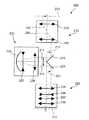
図2に、本発明にしたがった投影対物レンズの1つの好適な実施形態の略図が示されている。この投影対物レンズ200を用いて、マスクのパターン(該対物レンズの物体平面201上に配置される)は、ある縮尺で、前記物体平面に対して平行に整合せしめられる該対物レンズの像平面202上にある縮尺で結像せしめられる。前記投影対物レンズは、物体フィールドを結像させて第1の中間実像211を形成する第1の屈折性対物レンズ部分210と、前記第1の中間像を結像させて第2の中間実像221を形成する第2のカタジオプトリック対物レンズ部分220と、前記第2の中間像をある縮尺で像平面202上に結像させる第3の屈折性対物レンズ部分230とを有する。前記カタジオプトリック対物レンズ部分220は、凹面鏡225を有する。第1の折曲鏡213は、前記第1の中間像に近接して、光軸204に対して45°の角度をなして配置されて、物体平面から到来する放射を凹面鏡225の方向に反射するようになっている。自身の平面状の鏡面が前記第1の折曲鏡の平面状の鏡面に対して直角をなして整合せしめられる第2の折曲鏡223は、凹面鏡225から到来する放射を像平面202の方向に反射する。 FIG. 2 shows a schematic diagram of one preferred embodiment of a projection objective according to the present invention. Using this
各折曲鏡213、223は、中間像に光学的に近接して配置されて、光伝導値が低値に保たれうるようになっている。中間像、すなわち近軸中間像と周辺光線中間像との間の領域全体は、好ましくは鏡面上には配置されず、以って結果的に中間像と鏡面との間において有限の最小距離が得られて、鏡面内におけるいかなる欠陥、たとえば傷または不純物も像平面上において鮮鋭に結像せしめられないようになっている。前記最小距離は、放射のサブアパチャー、すなわち特定のフィールド点から発するビームのフットプリントまたは鏡面上における範囲が、鏡面上において5mmまたは10mm未満の直径を有さないように設定されなければならない。両方の第1の中間像211が、すなわち第2の中間像221もまた、折曲鏡と凹面鏡225との間における幾何学的空間内に配置される(実線矢印)実施形態がある。この側部アームは、水平アーム(HOA)とも呼ばれる。また他の実施形態においては、第1の中間像211´は、第1の折曲鏡213の上流においてビーム路内に配置され得、第2の中間像221´は、第2の折曲鏡から下流においてビーム路内に配置されうる(破線により示される矢印)。 Each of the folding mirrors 213 and 223 is disposed optically close to the intermediate image so that the photoconductive value can be kept at a low value. The intermediate image, i.e. the entire region between the paraxial intermediate image and the peripheral ray intermediate image, is preferably not located on the mirror surface, so that there is a finite minimum distance between the intermediate image and the mirror surface. As a result, any defects in the mirror surface, such as scratches or impurities, cannot be sharply imaged on the image plane. Said minimum distance must be set so that the sub-aperture of radiation, ie the footprint or specular extent of the beam emanating from a particular field point, does not have a diameter of less than 5 mm or 10 mm on the specular surface. In some embodiments, both first
この例証的な実施形態における折曲げ角は、正確に90°である。これは、折曲鏡の鏡層の性能にとって有利である。90°より大または小の偏向もまた可能であり、これにより結果的に斜めに配置される水平アームが得られる。 The folding angle in this illustrative embodiment is exactly 90 °. This is advantageous for the performance of the mirror layer of the folding mirror. Deflections greater than or less than 90 ° are also possible, resulting in a horizontal arm that is obliquely arranged.
全ての対物レンズ部分210、220、230は、正の屈折力を有する。略図において、正の屈折力を有するレンズまたはレンズ群は、外方に向けられた先端を有する両方向矢印により表される一方で、負の屈折力を有するレンズまたはレンズ群は、これに対して、内方に向けられた頭部を有する両方向矢印により表される。 All the
第1の対物レンズ部分210は、正の屈折力を有する2つのレンズ群215、216からなり、前記レンズ群間に、実線により示される主光線203が鎖線により示される光軸204と交差する絞り可能位置がある。前記光軸は、第1の折曲鏡213において90°にわたって折り曲げられる。第1の中間像211は、第1の折曲鏡213からすぐ下流の光路内において生じしめられる。 The first
第1の中間像211は、後続のカタジオプトリック対物レンズ部分220に対して物体として作用する。この対物レンズ部分は、フィールドに近接する正レンズ群226と、絞りに近接する負のレンズ群227と、前記レンズ群からすぐ下流に配置されるとともに前記第1の中間像を結像させて第2の中間像221を形成する凹面鏡225とを有する。全体として正の作用を有する前記レンズ群226は、「フィールドレンズ」として用いられるとともに、正の単レンズによって形成されるが、前記単レンズの作用は、さらにまた、全体として正の屈折力を有する2個以上の個別のレンズによって生じしめられうる。負のレンズ群227は、負の作用を有する1個以上のレンズからなる。 The first
光学的に第2の折曲鏡223の直前に配置される第2の中間像221は、第3の屈折性対物レンズ部分230により像平面202上に結像せしめられる。この屈折性対物レンズ部分230は、第1の正のレンズ群235と、第2の負のレンズ群236と、第3の正のレンズ群237と、第4の正のレンズ群238とを有する。前記正のレンズ群237、238間において、主光線が光軸を横切る絞り可能位置がある。 The second
図3に、本質的に図2を参照して説明された原理を用いて形成される投影対物レンズ300のレンズ断面図が示されている。同一または対応する要素または要素群は、図2の場合と同じ参照符号に100を加えた参照符号を用いて示されている。 FIG. 3 shows a lens cross section of a
このシステムの1つの特別な特徴は、ビームが2つの対向する方向に通過する両凸正レンズ326が、幾何学的に折曲鏡313、323と凹面鏡325との間において、ビームが2回通過する投影対物レンズ領域内に設けられるところにあり、ビームは、前記両凸正レンズの互いに偏移するレンズ部分を、第1の中間像311と凹面鏡325との間における光路内と、前記凹面鏡と第2の中間像321または像平面302との間における光路内との両方において通過する。この正レンズ326は、凹面鏡325より折曲鏡313、323により接近して、特に前記折曲鏡と前記凹面鏡との間における軸方向距離の最初の3分の1以内に配置される。正レンズ326の領域において、周辺光線高さは、主光線高さに比べて小さくなり、主光線高さに対する周辺光線高さの比は、約0.3となる。これにより、正レンズ326は、第1の中間像311と第2の中間像321との両方に対して、フィールドに接近して配置されるとともに、以って両方の中間像に対してフィールドレンズとして作用する。第1の中間像311と凹面鏡325との間における光路内の正の屈折力は、とりわけ、後続のレンズ327および凹面鏡325の直径が小さく保たれうることを保証する。前記凹面鏡から第2の中間像321に至るとともに、さらに像平面へと至る光路内における正の屈折力は、さらにまた第2の折曲鏡323に到達する放射の入射角バンド幅の縮小をもたらすとともに、以って前記第2の折曲鏡を有利な反射層により被覆することができ、さらにまた像フィールドに最も接近するとともに本質的に浸漬投影対物レンズの高い像側開口数(NA=1.20)をもたらす役割を担う屈折性対物レンズ部分330におけるレンズ直径が制限されることになる。 One special feature of this system is that a biconvex
前記正レンズは、それが必要とされる場合は、前記折曲鏡により妨害されることなく、2つの中間像に非常に近接する位置に移動せしめられて、強力な補正効果が可能となるようにされうる。フィールドに接近して配置される正の屈折力は、水平アームをより長くすることを可能にする。第1の中間像311における大きい開口のため、水平アームの長さは、一般に短縮されて、凹面鏡325と、前記凹面鏡のすぐ上流に配置される負レンズ群327内の負のメニスカスレンズとの直径が色補正に関連づけられるとともに、よって無制限に大きくされてはならないようになる。フィールドの近傍に正のレンズ群326を含むことにより、さらにまた、ペッツヴァル湾曲の補償によって(凹面鏡と比べて)負レンズ327の屈折力が増大するとともに、以って凹面鏡の領域において相対的に小直径で縦色誤差の補正が向上する。これにより、カタジオプトリック対物レンズ部分は、コンパクトで、かつ相対的に小さいレンズ直径を有して設計されて、適正な色補正が得られうる。 The positive lens is moved to a position very close to the two intermediate images without being disturbed by the folding mirror, if required, so that a strong correction effect is possible. Can be. The positive refractive power placed close to the field allows the horizontal arm to be longer. Due to the large aperture in the first
2つの中間像311、321にすぐ近接して配置されるフィールドレンズ326もまた、光学的な補正に関して、以下の本文により詳細に説明されるように、重要な利点を有する。原則的に、重要な収差を受ける中間像に近接して光学面を有することは、結像誤差の補正に有利である。その理由は、下記のとおりである:中間像から長距離の位置、たとえばシステム絞りまたは該絞りの共役平面に近接する位置において、光ビームの全ての開放光線は、瞳座標とともに単調に上昇する有限の高さを有し、すなわち光学面は、全ての開放光線に作用する。瞳縁部においてさらに外方に配置される開放ビームもまた、この面上において漸進的に増大する高さ(すなわち、より正確には、主光線から漸増的な距離)を有する。 A
しかしながら、著しい収差を受ける中間像に近接する位置においては、この限りではない。実際に、中間像の火面内に配置される場合は、前記面は、略周辺光線像内または周辺光線像に近接して配置され得、すなわち周辺光線に対して効果的には作用しないが、帯域光線に対して著しい光学効果を有する。このため、たとえば光学収差における輪帯収差を補正することが可能になる。この原理を用いて、たとえば球面輪帯収差に故意に影響を与えることができる。 However, this is not the case at a position close to the intermediate image that receives significant aberration. In fact, when placed in the fire plane of the intermediate image, the plane may be placed in or near the peripheral ray image, i.e., it does not act effectively on the peripheral ray. , Has a significant optical effect on band rays. For this reason, for example, it becomes possible to correct the zonal aberration in the optical aberration. This principle can be used to intentionally affect, for example, spherical annular aberration.
中間像311、321に対向するとともに前記中間像にすぐ隣接して配置される正レンズ326の凸レンズ面は、非球面状の曲面とされる。フィールドに近接した配置とともに、これにより、非常に重要な補正効果を達成することが可能になる。 The convex lens surface of the
像に最も接近する少なくとも2〜3個のレンズをフッ化カルシウムにより製造して、圧密の問題を回避することができる。固有複屈折を補償するために、これらのレンズの主結晶軸は、互いに対して回転せしめられうる。凹面鏡325は、さらにまた、鏡面の形状が適切なマニピュレータにより変動せしめられうるアクティブミラーの形態をとりうる。これを用いて、さまざまな結像誤差を補償することができる。前記中間像の少なくとも一方に近接するビーム路は、実質的にテレセントリックである。 At least a few lenses closest to the image can be made with calcium fluoride to avoid the compaction problem. In order to compensate for the intrinsic birefringence, the main crystal axes of these lenses can be rotated with respect to each other. The
表1に、設計の詳細が表形式で示されている。この場合は、第1欄に、屈折性、反射性またはその他の態様で指定される面の番号が示されており、第2欄に、その面の半径r(単位:mm)が示され、第3欄には、その面と後続の面との間における距離d(単位:mm)が示され、第4欄には、素子の材料が示され、第5欄には、その光学素子の光学的に利用可能な有効半径(単位:mm)が示されている。屈折面は、第1欄において、「R」により示されている。表2に、対応する非球面データが示されており、これらの非球面の矢高は、下式を用いて計算されている:
この場合、半径の逆数(1/r)は、面頂点における面曲率であり、hは、面点と光軸間の距離である。したがって、矢高は、p(h)、すなわち前記面点と前記面頂点との間におけるz方向、すなわち光軸方向の距離である。定数K、C1、C2等は、表2に示されている。 In this case, the reciprocal of the radius (1 / r) is the surface curvature at the surface vertex, and h is the distance between the surface point and the optical axis. Therefore, the arrow height is p (h), that is, the distance in the z direction, that is, the optical axis direction, between the surface point and the surface vertex. The constants K, C1, C2, etc. are shown in Table 2.
浸漬対物レンズ300は、全てのレンズに用いられるフッ化カルシウムがn=1.5593の屈折率を有する約157nmの動作波長用に設計される。これは、157nmにおいてnI=1.37である浸漬媒質として真空技術において用いられるパーフルオロエーテル(フォムブリン(Fomblin)登録商標)に適合化せしめられるとともに、約1.5mmの像側動作距離を有する。像側開口数NAは、1.2であり、像縮尺率は、4:1である。このシステムは、26×5.0mm2の大きさを有する像フィールド用に設計されるとともに、二重テレセントリック系である。The
図4に、図3に示された実施形態の変形態様を表すとともに、同様に図2を参照して説明された原理を用いて形成される投影対物レンズ400のレンズ断面図が示されている。同一または対応する要素または要素群は、図3の場合と同じ参照符号に100を加えた参照符号を用いて示されている。この例証的な実施形態の詳細は、表3および4に示されている。 FIG. 4 represents a variant of the embodiment shown in FIG. 3 and shows a lens cross-section of a
この実施形態においても、フィールドレンズとして用いられる両凸正レンズ426が、折曲鏡413、423と凹面鏡425の間に配置される中間像411、421に光学的にすぐ近接する水平アーム内に配置されて、以って小さい寸法を有する水平アームが得られる一方で、中間像に対する重要な補正効果がもたらされる。 Also in this embodiment, the biconvex
この実施形態のさらに他の特別な特徴は、小さい寸法と小さい最大直径とにより、特にコンパクトな構成を有する第3の屈折性対物レンズ部分430の設計にある。最初の正レンズ群435と後続の負レンズ群436および両者間に開口絞り(口径絞り)Aを有する2つの後続の正レンズ群437、438とを有する基本設計は、図3に示された設計に対応する。第3のレンズ群437の入射面Eは、ビーム直径の最大拡散領域内かつ周辺光線高さの変曲点の範囲内において、第2のレンズ群436内における唯一のレンズである両凸負レンズ436の後に配置される。この入射面と開口絞りAとの間、または前記開口絞りと像平面との間において、光学設計に重要である発散効果を有するいかなる負レンズも配置されない。特に、正レンズのみが、入射面Eと像平面との間において設けられる。 Yet another special feature of this embodiment lies in the design of the third refractive
有意な屈折力を有する負レンズが、ビーム直径が相対的に大きくなる領域内に存在しない場合は、このことは、レンズの最大直径がこの領域内において実行可能な大きさに制限されることを可能にする。「相対的に大きいビーム直径」は、本明細書の目的上、特にレンズ上における周辺光線高さが、潜在的な絞り位置、たとえばシステム絞り位置において、少なくとも周辺光線高さの半分の大きさになる場合に生じる。この方法は、負レンズの拡散効果は確かに補正のために望ましいかもしれないが、負レンズから下流におけるあらゆる拡散効果は、負レンズが存在しない場合に必要とされるレンズ直径より大きいレンズ直径をもたらす傾向にあることを考慮に入れている。さらにまた、ビームの光線は、下流の像平面の方向に互いに合同せしめられ、このために正の屈折力が必要とされる。この目的のために必要とされる正レンズは、ビームの合同において負レンズの拡散効果を補償する必要もないという条件で、全体として相対的に適度な設計とされうる。さらに、レンズの個数は、制限されうる。これにより、本発明は、最小限のレンズ寸法を有するコンパクトな投影対物レンズを得ることを可能にする。 If a negative lens with significant refractive power is not in the region where the beam diameter is relatively large, this means that the maximum diameter of the lens is limited to a feasible size in this region. to enable. A “relatively large beam diameter” is used for purposes of this specification, particularly when the marginal ray height on the lens is at least half the marginal ray height at a potential iris position, eg, the system iris position. Occurs when While this method may certainly be desirable for correction of the negative lens diffusing effect, any diffusing effect downstream from the negative lens will have a lens diameter larger than that required in the absence of the negative lens. Taking into account the tendency to bring. Furthermore, the rays of the beam are brought together in the direction of the downstream image plane, which requires a positive refractive power. The positive lens required for this purpose can be relatively moderately designed as a whole, provided that it is not necessary to compensate for the diffusive effect of the negative lens in the beam congruence. Furthermore, the number of lenses can be limited. Thereby, the present invention makes it possible to obtain a compact projection objective with minimal lens dimensions.
図5に、光学的な観点において、図2を参照して説明された原理に基づいて設計される投影対物レンズ500の1つの実施形態が示されている。同一または対応する要素または要素群は、図2の場合と同じ参照符号に300を加えた参照符号を用いて示されている。 FIG. 5 shows, from an optical point of view, one embodiment of a
図2と図5とに示されるシステムにおけるビーム形状間の比較から、異なるビーム路が、本発明の範囲内において可能であることがわかる。図2のシステムにおいては、物体平面から凹面鏡225へと進む第1のビーム部分と、前記凹面鏡から像平面へと進む第2のビーム部分とは、いかなる位置においても交差しないため、非交差ビーム路が示されている。これに対して、図5に示される実施形態は、交差ビーム路を有する。第1の折曲鏡513は、光軸504の側において、第2の折曲鏡523とは別の方向に向けられて配置され、第2の折曲鏡は、幾何学的に物体平面により接近して配置される。その結果として、物体平面501から凹面鏡525へと進む第1のビーム部分540と、凹面鏡525から第2の折曲鏡523を介して像平面へと進む第2のビーム部分550とは、第2の折曲鏡523の鏡面のすぐ上流の領域内において、中間像511、521に近接して交差する。この場合は、第2の中間像521は、光学的に第2の折曲鏡523の直前に、かつ前記第1の折曲鏡の光軸504に対向する内側鏡縁部528に幾何学的に近接して配置される。放射が、前記第1の折曲鏡により、いかなる口径食も生じることなく内側鏡縁部528の領域において第2の折曲鏡の方向に「付勢」されるこの交差ビーム路は、システムの光伝導値の最適化を可能にする。さらにまた、2個の折曲鏡のためのより大きい物理的空間が得られる。 From a comparison between the beam shapes in the systems shown in FIGS. 2 and 5, it can be seen that different beam paths are possible within the scope of the present invention. In the system of FIG. 2, the first beam portion that travels from the object plane to the
この実施形態においても、正のフィールドレンズ群526が、両方の中間像に光学的に近接して、幾何学的に前記折曲鏡と凹面鏡との間において配置されるが、前記第2の折曲鏡と前記第2の中間像とは、正レンズ526からいくらかさらに離れる。 Also in this embodiment, the positive
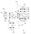
自身の物体平面601上に配置されるパターンを、前記物体平面に対して平行に整合せしめられる像平面602上に、2つの中間実像611、621を生じしめて結像させる投影対物レンズ600の1つの実施形態を、図6を参照して説明する。この投影対物レンズは、物体フィールドの第1の中間実像611を生じしめる第1のカタジオプトリック対物レンズ部分610と、前記第1の中間像を結像させて第2の中間実像621を形成する後続の第2のカタジオプトリック対物レンズ部分620と、前記第2の中間像621を直接、すなわちいかなるまた他の中間像も生じしめることなく、像平面602上に結像させる後続の第3の屈折性対物レンズ部分とを有する。 One of the
これまでに説明された実施形態との1つの重要な相違点は、第1の対物レンズ部分610が、コンパクトなカタジオプトリックサブシステムであるところにある。このカタジオプトリック対物レンズ部分610は、光軸が物体平面に対して直角をなす凹面鏡615と、物体平面と凹面鏡との間において配置され、かつ光軸604に対して45°に傾斜せしめられるとともに、投影対物レンズ610の第1の折曲鏡として用いられる平面状のビーム分割面613を有する偏光選択ビームスプリッター660(ビームスプリッタキューブBSC)とを有する。λ/4板661と第1の正レンズ群662と第2の正レンズ群663とビームスプリッター660とまた他のλ/4板664と凹面鏡の直前に配置される負レンズ群665とが、物体平面と凹面鏡との間において、前記順序で配置される。前記凹面鏡に続いて、さらに他のλ/4板666と正レンズ群667とが、折曲鏡613から下流においてビーム路内に配置される。フィールドに近接する位置に正レンズ群626を有する第2のカタジオプトリック対物レンズ部分620の基本構成は、本質的に図2に示された基本設計に対応する。第3の屈折性対物レンズ部分は、正レンズ群のみを有し、前記正レンズ群間に絞り位置が配置される。 One important difference from the embodiments described thus far is that the first
したがって、この例証的な実施形態においては、折曲は、この折曲を担う折曲鏡613と第1のサブシステムにより生じしめられる第1の中間像611との間において配置される少なくとも1個の正レンズ667の形態をとる正の屈折力を有する第1のカタジオプトリック対物レンズ部分内において起こる。全体としてのシステムは、第1のλ/4板により直線偏光放射に変換される円偏光入力光を用いて作用し、前記直線偏光放射は、斜めに配置されるビーム分割層613に対してp偏光されるとともに、よって本質的に完全に前記ビーム分割層を通過して凹面鏡650に達する。前記ビーム分割層と凹面鏡との間に配置されるλ/4板は、前記直線変更放射により2回通過されるとともに、この過程で偏光優先方向を90°にわたって回転させて、凹面鏡から偏光分割層613に到達する放射が前記層に対してs偏光されるとともに、後続の対物レンズ部分の方向に反射されるようにする。第3のλ/4板666は、放射を円偏光放射に変換し、然る後に前記放射は後続のサブシステムを通過する。 Thus, in this illustrative embodiment, the fold is at least one disposed between the
第1のカタジオプトリック対物レンズ部分610は、鏡の曲率と前記鏡の上流の負の屈折力とに関連して、像面湾曲と縦色収差とのいずれもが大体または完全に補正されうるように設計されうるため、後続の部分的な対物レンズは、これらの結像誤差の負荷を全くまたはわずかしか受けない。さらにまた、この構成では、物体平面と水平に整合せしめられるカタジオプトリック対物レンズ部分620との間における物理的空間を拡大させることが可能になり、これを利用して光伝導値を低減させることができる。 The first catadioptric
開口絞りAは、好ましくは、像に最も接近する第3の対物レンズ部分630内において、主光線が光軸と交差する位置に配置される。2つのさらに他の絞り可能位置が、第1および第2の対物レンズ部分内において、各々が凹面鏡615、625に接近して示されている。 The aperture stop A is preferably arranged at a position where the principal ray intersects the optical axis in the third
第1の対物レンズ部分は、物理的にコンパクトなものになりうる。図7に、図6に示されたシステムの第1の対物レンズ部分610として用いられうるカタジオプトリックサブシステムの実施形態が示されており、この実施形態の詳細は、表5に示されている。同一または対応する要素または要素群は、図6の場合と同じ参照符号に100を加えた参照符号を用いて示されている。全てのレンズは、球面状であり、全てのビーム分割ブロック760を含む透明要素は、合成石英ガラスにより構成される。 The first objective lens portion can be physically compact. FIG. 7 shows an embodiment of a catadioptric subsystem that can be used as the first
図8に、ビーム路を折り曲げるために設けられる折曲鏡のさまざまな実施態様の略図が示されている。これらの折曲鏡は、たとえば、特に表面鏡として独立型の平面鏡の形態をとりうる(図8(a)および(b))。この場合は、図2の実施形態においては、図8(b)に示されるような別個の鏡が一緒に保持されることも可能である。これらの折曲鏡は、さらにまた、図8(c)および(d)に示されるように、独立型のプリズムの形態をとりうる。反射プリズム面は、それが必要とされる場合は、自身上において生じる入射角によって内部全反射面として作用しうるか、または反射コートを有しうる。特に、図2〜4に示される実施形態では、これらの鏡は、図8(e)に示されるような鏡プリズムの外側反射面の形態もとりうる。 FIG. 8 shows a schematic diagram of various embodiments of a folding mirror provided for folding the beam path. These folding mirrors, for example, can take the form of stand-alone plane mirrors, particularly as surface mirrors (FIGS. 8A and 8B). In this case, in the embodiment of FIG. 2, separate mirrors as shown in FIG. 8 (b) can be held together. These folding mirrors can also take the form of stand-alone prisms, as shown in FIGS. 8 (c) and (d). The reflective prism surface, if it is required, can act as an internal total reflection surface, depending on the angle of incidence occurring on it, or it can have a reflective coat. In particular, in the embodiment shown in FIGS. 2-4, these mirrors can also take the form of an outer reflective surface of a mirror prism as shown in FIG. 8 (e).
図9に、図2を参照して説明されたようなR−C−R形の投影対物レンズ900のさらに他の実施形態が示されている。前記の基本構造に関する説明を参照する。第1の屈折性対物レンズ部分910は、物体面901内に配置される軸外有効物体フィールドOFを第1の中間像911に結像させるように設計される。第1の平面状の折曲鏡913は、前記第1の中間像のすぐ上流において第1の対物レンズ部分内に配置される。凹面鏡925を含む第2のカタジオプトリック対物レンズ部分920は、前記第1の中間像を、第2の折曲鏡923のすぐ上流において前記折曲鏡からある距離に配置される第2の中間像921に結像させるように設計される。自由に接近可能な開口絞りASを含む第3の屈折性対物レンズ部分930は、前記第2の中間像を、光軸の外側に配置される有効像フィールドIFが創出される像面902上に結像させるように設計される。前記第1の対物レンズ部分910は、中継システムとしての役割を果たして、前記第1の中間像を第1の折曲鏡913に接近させて配置する。第2のカタジオプトリック対物レンズ部分920は、前記折曲鏡に幾何学的に近接し、かつ両方の中間像に光学的に近接する位置において正の単レンズ(フィールドレンズ926)を含み、以ってフィールド関連の結像誤差の効率的な補正を可能にする。前記第3の対物レンズ部分は、本実施形態においては26mm・5.5mmのフィールドサイズの有効物体フィールドOFにおいてNA=1.20である像側開口数を得るために投影対物レンズの縮小率の重要な部分を提供する集束レンズ群としての役割を果たす。軌跡全長(物体面901と像面902との間における軸方向距離)は、1400mmである。波面収差は、約4mλrmsである。詳細は、表9、9Aに示されている。結像の主光線CRは、主光線の軌道を辿りやすくするために、実線で描かれている。 FIG. 9 shows yet another embodiment of an R-C-R
第1の対物レンズ部分910のレンズは、該レンズの回転対称軸であるとともに、物体面901に対して垂直をなす第1の光軸部分OA1を形成する。第2の対物レンズ部分の凹面鏡925とレンズとの回転対称軸は、本実施形態では、物体側の第1の光軸部分OA1に対して垂直に整合する、第2の光軸部分OA2を形成する。換言すれば、光軸は、第1の折曲鏡913により、90°折り曲げられる。第3の対物レンズ部分930のレンズは、第1の光軸部分OA1に対して平行かつ像面902に対して垂直をなす第3の光軸部分OA3を形成する。本実施形態において、物体側の第1の光軸部分OA1と像側の第3の光軸部分OA3とは同軸であって、いかなる側方軸偏移もこれらの光軸部分間において存在しないようになっている。この構成は、屈折性対物レンズ部分のレンズの取付けに関して望ましいかもしれない。第1および第3の光軸部分OA1、OA3が同軸である同様の構成が、図10に、投影対物レンズ1000として示されている。この設計の詳細は、表10、10Aに示されている。いずれの実施形態においても、有限値の物体像シフトOISが存在する。 The lens of the first
投影対物レンズ900において、第1の折曲鏡913のすぐ上流のレンズ面ASPは、第1の中間像に光学的に接近する非球面である。フィールド関連の結像誤差の効率的な補正が達成される。投影対物レンズ1000において、フィールドレンズ1026は、凹面鏡に対向する非球面状レンズ面ASPを有する。この非球面は、第1および第2の中間像1011、1021の両方に最も近接するレンズ面であり、したがってビーム路に沿った2点における補正に非常に効果的である。この設計の波面収差は、約3mλrmsである。 In the
図11に示される投影対物レンズ1100の実施形態(詳細は表11、11A)は、好適な実施形態において、物体側における第1の光軸部分OA1と像側における第3の光軸部分OA3との間における側方軸偏移AOが適切に調節されると、実際的な利点が得られることを実証する一例である。以下で用いられる用語を理解しやすくするために、図11´に、重要な特徴とパラメータとを示す略図が示されている。 In the preferred embodiment of the
光学的な観点から、軸外有効物体フィールドOFは、第1の対物レンズ部分1110により、第1の折曲鏡1113と第2の対物レンズ部分1120の正のフィールドレンズ1126との間に配置される第1の中間像1111に結像せしめられる。この第2の対物レンズ部分は、凹面鏡1125を含むとともに、結像サブシステムとして設計されて、正レンズ1126と第2の折曲鏡1123との間に配置される第2の中間像1121を創出する。第3の対物レンズ部分1130は、集束レンズ群としての役割を果たして、この場合はNA=1.30である非常に高い像側開口数NAで、軸外有効像フィールドIFを生じしめる。 From an optical point of view, the off-axis effective object field OF is disposed between the
図9および10の実施形態と対照的に、直角をなす平面により第1および第2の折曲鏡を形成する折曲プリズムが非対称的に用いられて、以って側方軸偏移AOが、物体側における第1の光軸部分OA1と像側における第3の光軸部分OA3との間において得られる(図11´参照)。この特定の実施形態において、軸偏移AOは、物体フィールド中心を通って第1の光軸部分OA1に対して平行に延在する物体フィールド中心軸OFCAと像フィールドIFの中心を通るとともに第3の光軸部分OA3に対して平行に延在する像フィールド中心軸IFCAとが一致する(同軸となる)ような態様に設定される。換言すれば、有効物体フィールドOFと像フィールドIFとの間には、いかなる物体像シフト(OIS)も存在しない。この特性は、一般に、軸外物体フィールドを有するカタジオプトリック投影対物レンズではなく、光軸を中心とする有効物体フィールドを有する投影対物レンズ(たとえば純屈折性の対物レンズまたは物理的ビーム分割機能を有するカタジオプトリック対物レンズまたは瞳オブスキュレーションを有する対物レンズ)でしか得られない。図11´から明らかなように、側方軸偏移AOの大きさは、OIS=0であることが望まれる場合は、側方軸偏移AOと像フィールド中心高さh´との和が、物体フィールド中心高さhと等しくなるように設定される。その場合は、以下のとおりとなる:
|AO|=|h*(1+|β|)|
本発明の好適な実施形態のまた他の有利な態様は、フィールドレンズの正の屈折力を適切に選択することに関する。以下に例証的に示されるように、屈折力を適正に選択することにより、NA=1.3またはNA=1.35等の非常に高い像側開口数を有する投影対物レンズを製造することが可能になる一方で、折曲鏡の上流および/または下流のレンズの最大寸法と投影対物レンズの軌跡全長とが適度に維持される。実証のために、図12に、NA=1.25の像側開口数と関連ある従来技術の対物レンズの軌跡長(1400mm、国際特許第2004/019128A1号の図19)より小さい1250mmの軌跡長とを有する、国際特許第2004/019128号に示されているようなR−C−R形の従来技術の投影対物レンズの変形態様が示されている。いかなるフィールドレンズも幾何学的に折曲鏡と凹面鏡との間に配置されない。In contrast to the embodiment of FIGS. 9 and 10, folding prisms that form first and second folding mirrors by a right-angled plane are used asymmetrically, so that the lateral axis deviation AO is And obtained between the first optical axis portion OA1 on the object side and the third optical axis portion OA3 on the image side (see FIG. 11 ′). In this particular embodiment, the axial deviation AO passes through the center of the object field center axis OFCA and the image field IF extending parallel to the first optical axis portion OA1 through the object field center and third. The image field center axis IFCA extending in parallel with the optical axis portion OA3 is set so as to coincide (coaxial). In other words, there is no object image shift (OIS) between the effective object field OF and the image field IF. This characteristic is generally not a catadioptric projection objective with an off-axis object field, but a projection objective with an effective object field centered on the optical axis (eg a purely refractive objective or a physical beam splitting function). Can only be obtained with a catadioptric objective lens or an objective lens with pupil obscuration. As is apparent from FIG. 11 ′, when the size of the lateral axis deviation AO is desired to be OIS = 0, the sum of the lateral axis deviation AO and the image field center height h ′ is Are set to be equal to the object field center height h. In that case:
| AO | = | h* (1+ | β |) |
Another advantageous aspect of the preferred embodiment of the invention relates to the proper selection of the positive refractive power of the field lens. As shown exemplarily below, it is possible to produce a projection objective with a very high image-side numerical aperture, such as NA = 1.3 or NA = 1.35, by properly selecting the refractive power. While being possible, the maximum dimensions of the lens upstream and / or downstream of the folding mirror and the total trajectory length of the projection objective are reasonably maintained. For demonstration purposes, FIG. 12 shows a trajectory length of 1250 mm which is smaller than the trajectory length of the prior art objective lens (1400 mm, FIG. 19 of International Patent Publication No. 2004 / 019128A1) associated with an image side numerical aperture of NA = 1.25 A variant of an R-C-R type prior art projection objective as shown in WO 2004/019128 is shown. No field lens is geometrically placed between the folding mirror and the concave mirror.
比較のために、図13に、本発明の一実施形態として、正のフィールドレンズ1326が幾何学的に折曲鏡1313、1323と凹面鏡1325との間に配置される、同じ開口数(NA=1.25)と軌跡長(1250mm)とを有する投影対物レンズ1300が示されている。比較しやすくするために、図14の略図において、フィールドレンズを有さない従来技術のシステムが(a)に、フィールドレンズFLを含む本発明の実施形態が(b)に示されている。主光線CRの軌道は、図12および13において実線で描かれるとともに、加えて周辺光線MRの軌道も示されている図14にも略示されている。 For comparison, FIG. 13 shows, as an embodiment of the present invention, a
次に、図12の実施形態に関連ある従来技術のシステムのいくつかの独特な特徴を、図14(a)の参照符号を用いて要約する。第1の対物レンズ部分は、第1の中間像IMI1を折曲プリズムの第1の折曲鏡FM1に近接して創出するように設計される屈折性中継レンズ群L1である。凹面鏡CMを含む軸方向にコンパクトな(短い)第2のカタジオプトリック対物レンズ部分は、第2の中間像IMI2を第2の折曲鏡FM2に近接して創出する。第3の対物レンズ部分により形成される純屈折性の主集束レンズ群L2は、像を形成する。 Next, some unique features of the prior art system related to the embodiment of FIG. 12 are summarized using the reference numerals of FIG. 14 (a). The first objective lens part is a refractive relay lens group L1 designed to create a first intermediate image IMI1 close to the first folding mirror FM1 of the folding prism. The axially compact (short) second catadioptric objective part including the concave mirror CM creates a second intermediate image IMI2 in proximity to the second folding mirror FM2. The purely refractive main focusing lens unit L2 formed by the third objective lens portion forms an image.
前記第1の対物レンズ部分は、第1のレンズ群LG1と第2のレンズ群LG2(各々が正の屈折力)とに細分され、瞳面は、これらのレンズ群間において、主光線CRが光軸OAと交差する位置に配置される。第3の対物レンズ部分は、正の屈折力を有する第3のレンズ群LG3と、負の屈折力を有する第4のレンズ群LG4と、正の屈折力を有する第5のレンズ群LG5とを前記の順序で含む。像側瞳面は、この第3の対物レンズ部分内において、主光線が光軸と交差する位置に配置される。開口絞りASは、一般に、この位置に配置される。光学的に第1および第2の中間像間の瞳面は、凹面鏡CMに近接する位置または該凹面鏡の位置に配置される。 The first objective lens portion is subdivided into a first lens group LG1 and a second lens group LG2 (each having a positive refractive power). The pupil plane has a principal ray CR between these lens groups. It arrange | positions in the position which cross | intersects optical axis OA. The third objective lens portion includes a third lens group LG3 having a positive refractive power, a fourth lens group LG4 having a negative refractive power, and a fifth lens group LG5 having a positive refractive power. Including in the above order. The image-side pupil plane is disposed at a position where the principal ray intersects the optical axis in the third objective lens portion. The aperture stop AS is generally arranged at this position. Optically, the pupil plane between the first and second intermediate images is arranged at a position close to or at the position of the concave mirror CM.
これに代わる方法として、開口絞りは、さらにまた、また他の瞳面の一方、すなわち屈折性中継レンズ群L1内またはカタジオプトリックレンズ群内において、凹面鏡に接近して配置されうる。 As an alternative, the aperture stop can also be placed close to the concave mirror in one of the other pupil planes, ie in the refractive relay lens group L1 or in the catadioptric lens group.
主光線CRは、第1の中間像IMI1と該中間像に光学的に近接する第1の折曲鏡とにおいて収束する。ここで、収束する主光線は、主光線高さCRH、すなわち主光線と光軸との間における半径方向距離が、光の伝播方向に減少していく主光線である。その一方で、主光線は、第2の中間像IMI2と第2の折曲鏡とにおいて発散する(すなわち主光線高さが光の伝播方向に増加していく)。 The chief ray CR converges at the first intermediate image IMI1 and the first folding mirror that is optically close to the intermediate image. Here, the convergent principal ray is a principal ray in which the principal ray height CRH, that is, the radial distance between the principal ray and the optical axis decreases in the light propagation direction. On the other hand, the chief ray diverges in the second intermediate image IMI2 and the second folding mirror (that is, the chief ray height increases in the light propagation direction).
折曲鏡と凹面鏡との間において中間像を有する折曲形状により、第1の中間像および第2の中間像に最も近い第2のレンズ群LG2および第3のレンズ群LG3は、折曲鏡がこれらのレンズと中間像との間に配置されるため、それぞれ光学的に前記中間像から相対的に遠くに位置する。主光線の収束/発散の結果として、折曲鏡に最も近い前記レンズは、大型(大きいレンズ直径)になる傾向を有する。この効果は、より大きい距離が凹面鏡と折曲鏡との間において設定されて、以ってより長い水平アーム(HOA)の対物レンズが形成される場合には、より弱くなりうることに注意されたい。 The second lens group LG2 and the third lens group LG3 that are closest to the first intermediate image and the second intermediate image have a bent mirror having a bent shape having an intermediate image between the bent mirror and the concave mirror. Are arranged between these lenses and the intermediate image, so that they are optically positioned relatively far from the intermediate image. As a result of chief ray convergence / divergence, the lens closest to the folding mirror tends to be large (large lens diameter). Note that this effect can be weaker if a larger distance is set between the concave mirror and the folding mirror, thus forming a longer horizontal arm (HOA) objective lens. I want.
これらの条件を考慮すると、水平光軸は、像側開口数NAを増大せしめると短くなる傾向を有する。このことは、以下のように理解されうる。凹面鏡の第1の目的は、投影対物レンズのペッツヴァルの和(像面湾曲)を補正することにある。ペッツヴァルの和の補正に対する凹面鏡の寄与度は、凹面鏡の曲率に直接比例する。システムの開口数を増大させるとともに、同時に水平アームHOAの長さを一定に保てば、凹面鏡を含むカタジオプトリックレンズ群の直径は増加する。その1つの潜在的な結果として、凹面鏡の曲率は、より小さくなり、以ってペッツヴァルの和の補正に対する凹面鏡の効果は低下する。このことは、その場合にはペッツヴァルの和の補正が投影対物レンズのその他の部分において達成されなければならなくなり、以って設計がより複雑になるため、あまり望ましくないと考えられる。 Considering these conditions, the horizontal optical axis tends to become shorter as the image-side numerical aperture NA is increased. This can be understood as follows. The first purpose of the concave mirror is to correct the Petzval sum (field curvature) of the projection objective. The contribution of the concave mirror to the Petzval sum correction is directly proportional to the curvature of the concave mirror. Increasing the numerical aperture of the system and simultaneously keeping the length of the horizontal arm HOA constant increases the diameter of the catadioptric lens group including the concave mirror. One potential consequence of this is that the curvature of the concave mirror is smaller, which reduces the effect of the concave mirror on Petzval sum correction. This is considered less desirable because in that case Petzval sum correction would have to be achieved in other parts of the projection objective, thus making the design more complex.
その一方で、ペッツヴァルの和の補正に対するカタジオプトリックレンズ群の補正効果を維持することが望まれる場合は、凹面鏡を含むカタジオプトリックレンズ群の直径を本質的に一定に維持しなければならない。しかし、このことは、水平アームの長さを減じることに対応し、これは、図14(a)の略図および図12の投影対物レンズ1200に示されるように、中間像における相対的に大きい主光線角をもたらす。 On the other hand, if it is desired to maintain the correction effect of the catadioptric lens group on the Petzval sum correction, the diameter of the catadioptric lens group including the concave mirror must be kept essentially constant. Don't be. However, this corresponds to reducing the length of the horizontal arm, which is relatively large in the intermediate image, as shown in the schematic of FIG. 14 (a) and the
図12から、非常に大きいレンズ直径が、特に第1の折曲鏡のすぐ上流の第2のレンズ群LG2の2個または3個の正レンズに関して必要とされることがわかる。 From FIG. 12, it can be seen that a very large lens diameter is required, especially for two or three positive lenses of the second lens group LG2 immediately upstream of the first folding mirror.
しかしながら、開口数を増大させることが望まれる場合は、第3の対物レンズ部分内において、主にウェーハに隣接する最も近い瞳位置の近傍に十分なレンズ間隔を設けなければならない。さらにまた、対物レンズの軌跡長を妥当な値に制限することが望まれる場合は、第1の対物レンズ部分(中継レンズ群L1)を軸方向により短く設計するとともに、第1の折曲鏡のすぐ上流のレンズの直径を減じることが望ましいと思われる。 However, if it is desired to increase the numerical aperture, sufficient lens spacing must be provided in the third objective lens portion, primarily in the vicinity of the closest pupil position adjacent to the wafer. Furthermore, when it is desired to limit the trajectory length of the objective lens to an appropriate value, the first objective lens portion (relay lens group L1) is designed to be shorter in the axial direction, and the first folding mirror It may be desirable to reduce the diameter of the lens immediately upstream.
これらの目的は、図14(b)の略図および図13の実施形態1300に例証的に示されるように、十分な正の屈折力を有するフィールドレンズを、幾何学的に、中間像に光学的にもっとも近い前記折曲鏡と凹面鏡との間に導入することによって達成されうる。図13からわかるように、レンズ1326によって得られる正の屈折力は、主光線CRを光軸に対して略平行に、または第1の折曲鏡1313上に若干発散させて案内することを可能にし、以って第1の折曲鏡のすぐ上流の2個または3個のレンズの直径は、図12の設計と比べた場合に実質的に減じられうる。さらにまた、第1の対物レンズ部分1310の第1の軸方向長さAL1は、図12の第1の対物レンズ部分1210の対応する長さと比べた場合に、実質的に減じられる。その結果として、第3の対物レンズ部分内において、開口数の増大に寄与するレンズを導入するためのより大きい空間を得ることができる。また、フィールドレンズを導入すると、凹面鏡を含む水平アームは、実質的により長くなり、凹面鏡は、実質的により小さくなる。 These objectives are to provide a field lens with sufficient positive power, geometrically optically coupled to the intermediate image, as illustrated in the schematic of FIG. 14 (b) and the
図3の実施形態において、さらにまた、第1および第2の両方の中間像は、フィールドレンズ1326と、凹面鏡1325を含む鏡群との間における空間内に配置されることがわかる。特に、中間像と最も近い光学面(凹面鏡に対向する正レンズ1326のレンズ面)との間における軸方向距離が十分に大きくなって、前記最も近い光学面は、軸方向に近軸中間像(近軸光線により形成される中間像)と周辺光線中間像(結像の周辺光線により形成される)との間において形成される中間像空間の外側に位置するようになる。少なくとも10mmの最小距離が、この場合に得られる。フィールドレンズは、第1の対物レンズ部分1310の最後のレンズとして、かつ第3の対物レンズ部分1330の第1のレンズ(縮小投影対物レンズとしての意図される用途において光伝播方向に見た場合)として効果的である。したがって、図13が、1個のレンズ(フィールドレンズ1326)が光学的に第1および第3の両方の結像サブシステム内に配置される、2つの屈折性結像サブシステム(第1の対物レンズ部分1310と第3の対物レンズ部分1330とによって形成される)を有する投影対物レンズの図であることは、注目に値する。さらにまた、各折曲鏡は、屈折性結像サブシステム内において、それぞれのサブシステムのレンズ間に配置される。 In the embodiment of FIG. 3, it can also be seen that both the first and second intermediate images are located in the space between the
以下の図15〜17の実施形態(詳細はそれぞれ表15、15A、16、16Aおよび17、17Aに示す)は、図13の実施形態を基本とするとともに、十分な屈折力を有するフィールドレンズを有する基本設計が適度なレンズ寸法でさらに一層高い像側開口数を得ることを可能にすることを例証的に示している。詳細は、それぞれ表15、15A、16、16Aおよび17、17Aに示されている。 The following embodiments of FIGS. 15 to 17 (details are shown in Tables 15, 15A, 16, 16A and 17, 17A, respectively) are based on the embodiment of FIG. 13 and have a field lens having sufficient refractive power. It is exemplarily shown that the basic design that it is possible to obtain even higher image side numerical apertures with reasonable lens dimensions. Details are shown in Tables 15, 15A, 16, 16A and 17, 17A, respectively.
N=1.30の像側開口数が、図15の投影対物レンズ1500において得られる。ここで、主光線CRは、第1および第2の折曲鏡において光軸に対して略平行になる。特に、|CRA1|=0.055の第1の主光線方向余弦が第1の折曲鏡において得られ、CRA2=0.058の第2の主光線方向余弦が第2の折曲鏡において得られる。 An image side numerical aperture of N = 1.30 is obtained in the
投影対物レンズ1300および1500において、水平アーム内の正のフィールドレンズ1326、1526は、折曲鏡に非常に接近して配置されて、続いて、中間像が、前記フィールドレンズと凹面鏡との間において光学材料がない空間内に配置されるようになる。しかし、交差するレンズ形記号から明らかなように、1個以上の切り詰められたレンズが、折曲鏡に近接して用いられなければならず、このことは、レンズの取付けをより複雑にする。 In the
このような取付けの問題は、正のフィールドレンズ1626が、折曲鏡1613、1623から遠く離れて、前記折曲鏡のすぐ上流および下流のレンズ間に形成される円筒状空間のほとんど外側において配置される図16の投影対物レンズ1600において回避される。この実施形態においては、安定な取付け技術を用いる円形レンズが用いられうる。光学的な観点から、第1および第2の折曲鏡における主光線角は、略零(本質的にテレセントリックな主光線)となる。いずれの中間像1611および1621も本質的に折曲鏡とフィールドレンズ1626との間に配置されるため、前記フィールドレンズは、この場合は、凹面鏡1625を含む第2のカタジオプトリック結像対物レンズ部分1620の一部分となる。この変形態様では、折曲鏡に近接した設置空間の問題が回避される。NA=1.30の像側開口数が得られる。 Such a mounting problem is that the
この設計型式は、さらに一層高い開口数が得られる潜在性を有しており、このことは、NA=1.35の像側開口数を有する、図17に示される投影対物レンズ1700から明らかである。図16の実施形態の場合と同様に、主光線は、折曲鏡において略テレセントリックとなり、中間像1711、1721は、本質的に、折曲鏡とフィールドレンズ1726との間に配置される。図16の実施形態に対して開口数が増大することから、この実施形態では、さらに他の、かつ/またはより強いレンズのための十分な空間が、高開口数をもたらす役割を担う第3の対物レンズ部分内において得られうることがわかる。 This design type has the potential to obtain even higher numerical apertures, which is evident from the
すでに記載のように、本発明により、相対的に少量の光学材料を用いて製造されうる、特にNA>1の開口数での浸漬リソグラフィーを可能にする高開口数を有するカタジオプトリック投影対物レンズを製造することができる。以下に、特にコンパクトな投影対物レンズが製造されうることを表すパラメータを考慮して、材料消費量が潜在的に少量であることを実証する。 As already described, the present invention enables a catadioptric projection objective with a high numerical aperture that can be produced with a relatively small amount of optical material, in particular enabling immersion lithography with a numerical aperture of NA> 1. A lens can be manufactured. In the following, it will be demonstrated that the material consumption is potentially small, taking into account the parameters representing that particularly compact projection objectives can be produced.
一般に、投影対物レンズの寸法は、像側開口数NAが増大すると、劇的に増大する傾向にある。経験的に、最大レンズ直径Dmaxは、NAの増大とともにDmax〜NAkにしたがって線形を上回って著しく増加する傾向にあることがわかった。k=2の値は、本明細書の目的上用いられる近似値である。さらにまた、最大レンズ直径Dmaxは、像フィールドの大きさ(像フィールド高さY´により表され、ここで、Y´は、像フィールド点と光軸との間における最大距離である)に比例して増加することがわかった。本明細書
の目的上、線形の従属性が仮定される。これらの考慮事項に基づいて、第1の小型性パラメータCOMP1は、下記のように定義される:
COMP1=Dmax/(Y´・NA2)
任意の値の像フィールド高さと開口数とにおいて、第1の小型性パラメータCOMP1は、コンパクトな設計が望まれる場合には、可能な限り小さくならなければならないことが明らかである。In general, the size of the projection objective tends to increase dramatically as the image-side numerical aperture NA increases. Empirically, it has been found that the maximum lens diameter Dmax tends to increase significantly above linear according to Dmax to NAk with increasing NA. The value k = 2 is an approximation used for the purposes of this specification. Furthermore, the maximum lens diameter Dmax is proportional to the size of the image field (represented by the image field height Y ′, where Y ′ is the maximum distance between the image field point and the optical axis). And found that it increased. For the purposes of this specification, a linear dependency is assumed. Based on these considerations, the first compactness parameter COMP1 is defined as follows:
COMP1 = Dmax / (Y ′ · NA2 )
It is clear that for any value of image field height and numerical aperture, the first compactness parameter COMP1 should be as small as possible if a compact design is desired.
投影対物レンズを得るために必要な全体としての材料消費量を考慮すると、レンズの絶対数NLもまた直接的に関連する。一般に、より少数のレンズを有するシステムは、より多数のレンズを有するシステムより好ましい。したがって、第2の小型性パラメータCOMP2は、下記のように定義される:
COMP2=COMP1・NL
この場合も、COMP2が小値であることは、コンパクトな光学システムであることを示す。Considering the overall material consumption required to obtain a projection objective, the absolute number of lenses NL is also directly related. In general, a system having a smaller number of lenses is preferred over a system having a larger number of lenses. Therefore, the second compactness parameter COMP2 is defined as follows:
COMP2 = COMP1 · NL
Again, a small value of COMP2 indicates a compact optical system.
さらに、本発明の好適な実施形態にしたがった投影対物レンズは、入口側のフィールド面を光学的に共役な出口側のフィールド面に結像させる少なくとも3個の対物レンズ部分を有しており、結像対物レンズ部分は、中間像で連結される。一般に、投影対物レンズの製造に必要なレンズの個数および全体としての材料は、光学システムの結像対物レンズ部分の個数NOPが増えると増加する。対物レンズ部分毎の平均レンズ数NL/NOPを可能な限り少数に維持することが望ましい。したがって、第3の小型性パラメータCOMP3は、下記のように定義される:
COMP3=COMP1・NL/NOP
この場合も、光学材料の消費量が少ない投影対物レンズは、COMP3が小値であることを特徴とする。Furthermore, a projection objective according to a preferred embodiment of the present invention comprises at least three objective parts for imaging the entrance field field onto the optically conjugate exit field field; The imaging objective part is connected with an intermediate image. In general, the number of lenses and the overall material required for the production of projection objectives increases as the number NOP of imaging objective parts of the optical system increases. It is desirable to keep the average number of lenses NL / NOP per objective lens portion as small as possible. Therefore, the third compactness parameter COMP3 is defined as follows:
COMP3 = COMP1 · NL / NOP
Also in this case, a projection objective lens that consumes less optical material is characterized in that COMP3 is a small value.
表18に、小型性パラメータCOMP1、COMP2、COMP3の計算に必要な値と、詳細表(表の番号(同じ番号の図に対応)は、表18の第1欄に示されている)に示された各々のシステムに関するこれらのパラメータのそれぞれの値とがまとめられている。
したがって、少なくとも1個の凹面鏡と少なくとも2個の結像対物レンズ部分(すなわち少なくとも1個の中間像)とを有するコンパクトなカタジオプトリック投影対物レンズを得るためには、以下の条件(1)〜(3)の少なくとも1つが観察されなければならない:
(1) COMP1<11
好ましくは、COMP1<10.7が観察されるべきである。Table 18 shows the values required for the calculation of the compactness parameters COMP1, COMP2, COMP3, and a detailed table (the table numbers (corresponding to the same numbered figures) are shown in the first column of Table 18). The respective values of these parameters for each of the systems that have been compiled are summarized.
Therefore, in order to obtain a compact catadioptric projection objective having at least one concave mirror and at least two imaging objective parts (ie at least one intermediate image), the following condition (1) At least one of ~ (3) must be observed:
(1) COMP1 <11
Preferably, COMP1 <10.7 should be observed.
(2) COMP2<340
好ましくは、COMP2<320、さらに好ましくはCOMP2<300が観察されるべきである。(2) COMP2 <340
Preferably, COMP2 <320, more preferably COMP2 <300 should be observed.
(3) COMP3<110
好ましくは、COMP3<100が観察されるべきである。(3) COMP3 <110
Preferably, COMP3 <100 should be observed.
いくつかの実施形態においては、COMP1<11であり、かつ同時にCOMP2<340となって、これにより特にコンパクトな設計が可能になる。 In some embodiments, COMP1 <11 and at the same time COMP2 <340, which allows for a particularly compact design.
また他の態様は、いくつかの実施形態において最大のレンズに対して特に小さく、以って製造および取付けが容易である凹面鏡の大きさに関する。いくつかの実施形態では、凹面鏡は、鏡直径DMを有し、投影対物レンズは、最大レンズ直径Dmaxを有し、DM<0.75*Dmaxの条件が成り立つ。好ましくは、DM<0.70*Dmaxの条件が満たされうる。Yet another aspect relates to the size of the concave mirror, which in some embodiments is particularly small for the largest lens and thus is easy to manufacture and attach. In some embodiments, the concave mirror has a mirror diameter DM , the projection objective has a maximum lens diameter Dmax , and the condition DM <0.75* Dmax holds. Preferably, the condition of DM <0.70* Dmax can be satisfied.
表18から、本発明にしたがった好適な実施形態では、一般に、これらの条件の少なくとも一方が観察されることがわかり、本明細書に開示の設計規則によれば、適度な材料消費量および/または小さい凹面鏡を有するコンパクトな設計が得られることが示されている。 From Table 18, it can be seen that in preferred embodiments according to the present invention, generally at least one of these conditions is observed, and according to the design rules disclosed herein, reasonable material consumption and / or Or it has been shown that a compact design with a small concave mirror can be obtained.
物体平面から到来する放射を凹面鏡の方向に偏向させる第1の折曲鏡と、前記凹面鏡から到来する放射を像平面の方向に偏向させる第2の折曲鏡とを有するR−C−R形のカタジオプトリック投影対物レンズの例を用いて、本発明を詳細に説明した。本発明は、異なる折曲形状を有する設計、たとえば物体平面から到来する放射が、直接凹面鏡に向けられた後に、前記凹面鏡から到来する放射を像平面の方向に偏向させるように配置される第1の折曲鏡上において反射される設計でも実施されうる。これらの実施形態において、第2の折曲鏡は、一般に、第1の折曲鏡の下流に設けられて、物体平面と像平面との平行配置を可能にする。 RCR type having a first folding mirror for deflecting radiation coming from the object plane in the direction of the concave mirror and a second folding mirror for deflecting radiation coming from the concave mirror in the direction of the image plane The present invention has been described in detail using the example of the catadioptric projection objective. The present invention is a first design arranged to deflect radiation coming from the concave mirror in the direction of the image plane after the radiation coming from the object plane is directed directly to the concave mirror, for example in a design with different bending shapes. It can also be implemented in a design that is reflected on a folding mirror. In these embodiments, the second folding mirror is generally provided downstream of the first folding mirror to allow parallel placement of the object plane and the image plane.
前記の全てのシステムは、完全システム、すなわち実在の物体(たとえばフォトリソグラフィーマスク)から実像を(たとえばウェーハ上に)形成するシステムでありうることは自明である。しかし、これらのシステムは、より大きいシステムのサブシステムとしても用いられうる。したがって、たとえば、前記の1つのシステムの「物体」は、物体平面の上流に配置される結像システム(たとえば中継システム)により生じしめられる像でありうる。同様に、前記の1つのシステムによって形成される像は、像平面から下流のシステム(たとえば中継システム)において物体として用いられうる。「第1の対物レンズ部分」および「第2の対物レンズ部分」等の表現を用いて列挙される対物レンズ部分は、これらの対物レンズ部分が縮小対物レンズとして用いられる場合に、ビームがこれらの対物レンズ部分を通過する順序に関連する。「第1」および「第2」等の表現は、相対的なものとして理解されるべきである。「第1」の対物レンズ部分は、ビームが対物レンズ部分を通過する方向において、「第2」の対物レンズ部分の上流に配置される。この第1の対物レンズ部分は、必ずしも全体としてのシステムにおける第1の対物レンズ部分、すなわちシステム内において像平面のすぐ後続の対物レンズ部分である必要はない。しかしながら、図示された例証的な実施形態においては、そうである。
Claims (63)
Translated fromJapanese物体フィールドを結像させて第1の中間実像を形成する第1の対物レンズ部分と、
前記第1の対物レンズ部分から到来する放射を用いて第2の中間実像を生じしめる第2の対物レンズ部分と;
前記第2の中間実像を前記像平面上に結像させる第3の対物レンズ部分とを有し、
前記第2の対物レンズ部分は、凹面鏡を有するカタジオプトリック対物レンズ部分であり、
前記物体平面から到来する放射を前記凹面鏡の方向に偏向させる第1の折曲鏡と、前記凹面鏡から到来する放射を前記像平面の方向に偏向させる第2の折曲鏡とが設けられ;
正の屈折力を有するフィールドレンズが、前記第1の中間像と前記凹面鏡との間において、前記第1の中間像のフィールドに近接する領域内に配置されるカタジオプトリック投影対物レンズ。In a catadioptric projection objective that images a pattern placed on its own object plane onto its own image plane:
A first objective lens portion that images the object field to form a first intermediate real image;
A second objective lens portion that uses radiation coming from the first objective lens portion to produce a second intermediate real image;
A third objective lens portion for forming the second intermediate real image on the image plane;
The second objective part is a catadioptric objective part having a concave mirror;
A first folding mirror for deflecting radiation arriving from the object plane in the direction of the concave mirror and a second folding mirror for deflecting radiation arriving from the concave mirror in the direction of the image plane;
A catadioptric projection objective in which a field lens having a positive refractive power is disposed between the first intermediate image and the concave mirror in a region close to the field of the first intermediate image.
第2の折曲鏡が設けられて、前記凹面鏡から反射される放射を前記像平面へと偏向させ、前記第2の折曲鏡は、少なくとも部分的に、前記光軸の方向に前記物体平面と前記第1の折曲鏡との間において配置される軸方向領域内に配置される請求項1に記載の投影対物レンズ。A catadioptric objective portion having a concave mirror and a first folding mirror associated with the concave mirror that deflects radiation coming from the object plane to the concave mirror;
A second folding mirror is provided for deflecting radiation reflected from the concave mirror toward the image plane, the second folding mirror at least partially in the direction of the optical axis. The projection objective according to claim 1, wherein the projection objective is disposed in an axial region disposed between the first folding mirror and the first folding mirror.
物体フィールドを結像させて第1の中間実像を形成する第1の対物レンズ部分と、
前記第1の対物レンズ部分から到来する放射を用いて第2の中間実像を生じしめる第2の対物レンズ部分と;
前記第2の中間実像を前記像平面上に結像させる第3の対物レンズ部分とを有し、
前記投影対物レンズは、請求項1に記載のように設計される投影露光システム。In a projection exposure system for microlithography having an illumination system and a catadioptric projection objective that images a pattern placed on its own object plane onto its image plane:
A first objective lens portion that images the object field to form a first intermediate real image;
A second objective lens portion that uses radiation coming from the first objective lens portion to produce a second intermediate real image;
A third objective lens portion for forming the second intermediate real image on the image plane;
A projection exposure system, wherein the projection objective is designed as claimed in claim 1.
所定のパターンを有するマスクをカタジオプトリック投影対物レンズの物体平面の領域内に配置する段階と;
所定の波長の紫外光を用いて前記マスクを照明する段階と;
請求項1に記載のカタジオプトリック投影対物レンズを利用して、前記パターンの像を投影対物レンズの像平面の領域内に配置される感光基板上に投影する段階とからなる方法。In a method of manufacturing a semiconductor component and other microstructured elements:
Placing a mask having a predetermined pattern in the region of the object plane of the catadioptric projection objective;
Illuminating the mask with ultraviolet light of a predetermined wavelength;
A method comprising: projecting an image of the pattern onto a photosensitive substrate disposed within an area of an image plane of the projection objective using the catadioptric projection objective according to claim 1.
所定のパターンを有するマスクをカタジオプトリック投影対物レンズの物体平面の領域内に配置する段階と;
所定の波長の紫外光を用いて前記マスクを照明する段階と;
請求項1に記載のカタジオプトリック投影対物レンズを利用して、前記パターンの像を投影対物レンズの像平面の領域内に配置される感光基板上に投影する段階とからなり、
投影時において、ビームは、前記投影対物レンズの最後の光学素子と前記基板との間に配置される浸漬媒質を通過する方法。In a method of manufacturing a semiconductor component and other microstructured elements:
Placing a mask having a predetermined pattern in the region of the object plane of the catadioptric projection objective;
Illuminating the mask with ultraviolet light of a predetermined wavelength;
Using the catadioptric projection objective of claim 1 to project an image of the pattern onto a photosensitive substrate disposed within an image plane region of the projection objective;
During projection, the beam passes through an immersion medium disposed between the last optical element of the projection objective and the substrate.
物体フィールドを結像させて第1の中間実像を形成する第1の対物レンズ部分と、
前記第1の対物レンズ部分から到来する放射を用いて第2の中間実像を生じしめる第2の対物レンズ部分と;
前記第2の中間実像を前記像平面上に結像させる第3の対物レンズ部分とを有し、
前記第2の対物レンズ部分は、凹面鏡を有するカタジオプトリック対物レンズ部分であり;
前記物体平面から到来する放射を前記凹面鏡の方向に偏向させる第1の折曲鏡と、前記凹面鏡から到来する放射を前記像平面の方向に偏向させる第2の折曲鏡とが設けられ;
NA>0.85の像側開口数を有し、正の屈折力を有するフィールドレンズが、前記第1の中間像と前記凹面鏡との間において、前記第1の中間像のフィールドに近接する領域内に配置されるカタジオプトリック投影対物レンズ。In a catadioptric projection objective that images a pattern placed on its own object plane onto its own image plane:
A first objective lens portion that images the object field to form a first intermediate real image;
A second objective lens portion that uses radiation coming from the first objective lens portion to produce a second intermediate real image;
A third objective lens portion for forming the second intermediate real image on the image plane;
The second objective part is a catadioptric objective part having a concave mirror;
A first folding mirror for deflecting radiation arriving from the object plane in the direction of the concave mirror and a second folding mirror for deflecting radiation arriving from the concave mirror in the direction of the image plane;
A field lens having an image-side numerical aperture of NA> 0.85 and having a positive refractive power is close to the field of the first intermediate image between the first intermediate image and the concave mirror Catadioptric projection objective placed inside.
物体フィールドを結像させて第1の中間実像を形成する第1の対物レンズ部分と、
前記第1の対物レンズ部分から到来する放射を用いて第2の中間実像を生じしめる第2の対物レンズ部分と;
前記第2の中間実像を前記像平面上に結像させる第3の対物レンズ部分とを有し、
前記第2の対物レンズ部分は、凹面鏡を有するカタジオプトリック対物レンズ部分であり;
前記物体平面から到来する放射を前記凹面鏡の方向に偏向させる第1の折曲鏡と、前記凹面鏡から到来する放射を前記像平面の方向に偏向させる第2の折曲鏡とが設けられ;
前記第1および第2の折曲鏡は、前記物体平面から前記凹面鏡へと進む第1のビーム部分と、前記凹面鏡から前記像平面へと進む第2のビーム部分とが生じしめられる態様に構成され、一方の折曲鏡は、前記凹面鏡に対して、一方の前記ビーム部分が、前記折曲鏡上において折り曲げられるとともに、他方のビーム部分は、いかなる口径食も生じることなく前記折曲鏡を通過するような態様に構成され、前記第1のビーム部分と前記第2のビーム部分とは、交差領域内において交差するカタジオプトリック投影対物レンズ。In a catadioptric projection objective that images a pattern placed on its own object plane onto its own image plane:
A first objective lens portion that images the object field to form a first intermediate real image;
A second objective lens portion that uses radiation coming from the first objective lens portion to produce a second intermediate real image;
A third objective lens portion for forming the second intermediate real image on the image plane;
The second objective part is a catadioptric objective part having a concave mirror;
A first folding mirror for deflecting radiation arriving from the object plane in the direction of the concave mirror and a second folding mirror for deflecting radiation arriving from the concave mirror in the direction of the image plane;
The first and second folding mirrors are configured in such a manner that a first beam portion that travels from the object plane to the concave mirror and a second beam portion that travels from the concave mirror to the image plane are generated. One bending mirror is bent with respect to the concave mirror, and one of the beam portions is bent on the bending mirror, and the other beam portion does not cause any vignetting. A catadioptric projection objective configured to pass through, wherein the first beam portion and the second beam portion intersect in an intersecting region.
物体像シフト(OIS)は、物体フィールド中心と像フィールド中心との間において定義され、
有限物体中心高さhは、有効物体フィールドの前記物体フィールド中心と前記第1の光軸部分との間における側方距離として定義され、
倍率βを有し、
0≦OIS≦|h・(1+|β|)|
の条件が成り立つ請求項1に記載の投影対物レンズ。The lateral axis deviation AO is formed by the first optical axis portion and the second objective lens portion formed by the first objective lens portion, and is parallel to the first optical axis portion. Defined between the matching second optical axis portions,
Object image shift (OIS) is defined between the object field center and the image field center,
The finite object center height h is defined as the lateral distance between the object field center of the effective object field and the first optical axis portion,
Has a magnification β,
0 ≦ OIS ≦ | h · (1+ | β |) |
The projection objective according to claim 1, wherein:
|CRA1|<|β1*(YOB)/(LHOA)|
の関係が成り立ち、ここで、β1は、前記第1の対物レンズ部分の倍率であり、YOBは、主光線が考慮される最外側フィールド点の物体高さであり、LHOAは、前記第1の中間像から前記凹面鏡までの幾何学的距離(水平軸の長さ)である請求項1に記載の投影対物レンズ。The power and position of the field lens is relative to a first principal ray direction cosine CRA1 in the first intermediate image:
| CRA1 | <| β1* (YOB ) / (LHOA ) |
Where β1 is the magnification of the first objective lens portion, YOB is the object height at the outermost field point where the chief ray is considered, and LHOA is The projection objective according to claim 1, which is a geometric distance (length of a horizontal axis) from the first intermediate image to the concave mirror.
|CRA1|<|β1*(YOB)/(LHOA)|
|CRA2|<|β1*(YOB)/(LHOA)|
の条件が満たされる請求項1に記載の投影対物レンズ。A first chief ray direction cosine CRA1 in the first intermediate image and a second chief ray direction cosine CRA2 in the second intermediate image are defined;
| CRA1 | <| β1* (YOB ) / (LHOA ) |
| CRA2 | <| β1* (YOB ) / (LHOA ) |
The projection objective according to claim 1, wherein:
第1の屈折性結像対物レンズ部分と少なくとも1個の第2の屈折性結像対物レンズ部分とを有し、
少なくとも1個のレンズが、光学的に前記第1および第2の両方の結像対物レンズ部分内に配置される投影対物レンズ。In a projection objective that images a pattern placed on its own object plane onto its own image plane:
A first refractive imaging objective portion and at least one second refractive imaging objective portion;
A projection objective, wherein at least one lens is optically arranged in both the first and second imaging objective part.
物体フィールドを結像させて第1の中間実像を形成する第1の対物レンズ部分と、
前記第1の対物レンズ部分から到来する放射を用いて第2の中間実像を生じしめる第2の対物レンズ部分と;
前記第2の中間実像を前記像平面上に結像させる第3の対物レンズ部分とを有し、
― 前記第2の対物レンズ部分は、凹面鏡を有するカタジオプトリック対物レンズ部分であり;
前記物体平面から到来する放射を前記凹面鏡の方向に偏向させるか、または前記凹面鏡から到来する放射を前記像平面の方向に偏向させる第1の折曲鏡が設けられ;
正の屈折力を有するフィールドレンズが、幾何学的に前記第1の折曲鏡と前記凹面鏡との間において、前記第1の中間像のフィールドに近接する領域内に配置されるカタジオプトリック投影対物レンズ。In a catadioptric projection objective that images a pattern placed on its own object plane onto its own image plane:
A first objective lens portion that images the object field to form a first intermediate real image;
A second objective lens portion that uses radiation coming from the first objective lens portion to produce a second intermediate real image;
A third objective lens portion for forming the second intermediate real image on the image plane;
The second objective part is a catadioptric objective part having a concave mirror;
A first folding mirror is provided for deflecting radiation coming from the object plane in the direction of the concave mirror or deflecting radiation coming from the concave mirror in the direction of the image plane;
A catadioptric element in which a field lens having a positive refractive power is geometrically disposed between the first folding mirror and the concave mirror in a region close to the field of the first intermediate image. Projection objective.
物体像シフト(OIS)は、物体フィールド中心と像フィールド中心との間において定義され、
有限物体中心高さhは、有効物体フィールドの前記物体フィールド中心と前記第1の光軸部分との間における側方距離として定義され、
倍率βを有し、
0≦OIS≦|h・(1+|β|)|
の条件が成り立つ請求項47に記載の投影対物レンズ。The lateral axis deviation AO is formed by the first optical axis portion and the second objective lens portion formed by the first objective lens portion, and is parallel to the first optical axis portion. Defined between the matching second optical axis portions,
Object image shift (OIS) is defined between the object field center and the image field center,
The finite object center height h is defined as the lateral distance between the object field center of the effective object field and the first optical axis portion,
Has a magnification β,
0 ≦ OIS ≦ | h · (1+ | β |) |
48. The projection objective according to claim 47, wherein the following condition is satisfied.
|CRA1|<|β1*(YOB)/(LHOA)|
の関係が成り立ち、ここで、β1は、前記第1の対物レンズ部分の倍率であり、YOBは、主光線が考慮される最外側フィールド点の物体高さであり、LHOAは、前記第1の中間像から前記凹面鏡までの幾何学的距離(水平軸の長さ)である請求項47に記載の投影対物レンズ。The power and position of the field lens is relative to a first principal ray direction cosine CRA1 in the first intermediate image:
| CRA1 | <| β1* (YOB ) / (LHOA ) |
Where β1 is the magnification of the first objective lens portion, YOB is the object height at the outermost field point where the chief ray is considered, and LHOA is 48. Projection objective according to claim 47, which is a geometric distance (horizontal axis length) from the first intermediate image to the concave mirror.
COMP1=Dmax/(Y´・NA2)
COMP2=Dmax・NL/(Y´・NA2)
COMP3=Dmax・NL/(NOP・Y´・NA2)
であり、
(1)COMP1<11
(2)COMP2<340
(3)COMP3<110
の少なくとも1つの条件が満たされる請求項47に記載の投影対物レンズ。Having a maximum lens diameter Dmax , a maximum image field height Y ′, an image-side numerical aperture NA, NL lenses, and NOP imaging objective lens portions connected by an intermediate image;
COMP1 = Dmax / (Y ′ · NA2 )
COMP2 = Dmax · NL / (Y ′ · NA2 )
COMP3 = Dmax · NL / (NOP · Y ′ · NA2 )
And
(1) COMP1 <11
(2) COMP2 <340
(3) COMP3 <110
48. Projection objective according to claim 47, wherein at least one of the following conditions is satisfied.
物体フィールドを結像させて第1の中間実像を形成する第1の対物レンズ部分と、
前記第1の対物レンズ部分から到来する放射を用いて第2の中間実像を生じしめる第2の対物レンズ部分であって、凹面鏡を有するカタジオプトリック対物レンズ部分である第2の対物レンズ部分と;
前記第2の中間実像を前記像平面上に結像させる第3の対物レンズ部分と;
前記物体平面から到来する放射を前記凹面鏡の方向に偏向させるか、または前記凹面鏡から到来する放射を前記像平面の方向に偏向させる第1の折曲鏡とを有し、
側方軸偏移AOは、前記第1の対物レンズ部分により形成される第1の光軸部分と前記第2の対物レンズ部分により形成されるとともに前記第1の光軸部分に対して平行に整合する第2の光軸部分との間において定義され、
物体像シフト(OIS)は、物体フィールド中心と像フィールド中心との間において定義され、
有限物体中心高さhは、有効物体フィールドの前記物体フィールド中心と前記第1の光軸部分との間における側方距離として定義され、
倍率βを有し、
0≦OIS≦|h・(1+|β|)|
の条件が成り立つカタジオプトリック投影対物レンズ。In a catadioptric projection objective that images a pattern placed on its own object plane onto its own image plane:
A first objective lens portion that images the object field to form a first intermediate real image;
A second objective lens portion that is a catadioptric objective lens portion having a concave mirror, wherein the second objective lens portion generates a second intermediate real image using radiation coming from the first objective lens portion. When;
A third objective lens portion for forming the second intermediate real image on the image plane;
A first folding mirror for deflecting radiation coming from the object plane in the direction of the concave mirror or deflecting radiation coming from the concave mirror in the direction of the image plane;
The lateral axis deviation AO is formed by the first optical axis portion and the second objective lens portion formed by the first objective lens portion, and is parallel to the first optical axis portion. Defined between the matching second optical axis portions,
Object image shift (OIS) is defined between the object field center and the image field center,
The finite object center height h is defined as the lateral distance between the object field center of the effective object field and the first optical axis portion,
Has a magnification β,
0 ≦ OIS ≦ | h · (1+ | β |) |
Catadioptric projection objective that satisfies the above conditions.
|CRA1|<|β1*(YOB)/(LHOA)|
の関係が成り立ち、ここで、β1は、前記第1の対物レンズ部分の倍率であり、YOBは、主光線が考慮される最外側フィールド点の物体高さであり、LHOAは、前記第1の中間像から前記凹面鏡までの幾何学的距離(水平軸の長さ)である請求項55に記載の投影対物レンズ。The power and position of the field lens is relative to a first principal ray direction cosine CRA1 in the first intermediate image:
| CRA1 | <| β1* (YOB ) / (LHOA ) |
Where β1 is the magnification of the first objective lens portion, YOB is the object height at the outermost field point where the chief ray is considered, and LHOA is 56. Projection objective according to claim 55, which is the geometric distance (horizontal axis length) from the first intermediate image to the concave mirror.
COMP1=Dmax/(Y´・NA2)
COMP2=Dmax・NL/(Y´・NA2)
COMP3=Dmax・NL/(NOP・Y´・NA2)
であり、
(1)COMP1<11
(2)COMP2<340
(3)COMP3<110
の少なくとも1つの条件が満たされる請求項55に記載の投影対物レンズ。Having a maximum lens diameter Dmax , a maximum image field height Y ′, an image-side numerical aperture NA, NL lenses, and NOP imaging objective lens portions connected by an intermediate image;
COMP1 = Dmax / (Y ′ · NA2 )
COMP2 = Dmax · NL / (Y ′ · NA2 )
COMP3 = Dmax · NL / (NOP · Y ′ · NA2 )
And
(1) COMP1 <11
(2) COMP2 <340
(3) COMP3 <110
The projection objective according to claim 55, wherein at least one of the following conditions is satisfied.
― 物体フィールドを結像させて第1の中間実像を形成する第1の対物レンズ部分と、
― 前記第1の対物レンズ部分から到来する放射を用いて第2の中間実像を生じしめる第2の対物レンズ部分と;
― 前記第2の中間実像を前記像平面上に結像させる第3の対物レンズ部分とを有し、
― 前記第2の対物レンズ部分は、凹面鏡を有するカタジオプトリック対物レンズ部分であり;
― 前記物体平面から到来する放射を前記凹面鏡の方向に偏向させるか、または前記凹面鏡から到来する放射を前記像平面の方向に偏向させる第1の折曲鏡が設けられ;
最大レンズ直径Dmaxと、最大像フィールド高さY´と、像側開口数NAと、NL個のレンズと、中間像で連結されるNOP個の結像対物レンズ部分とを有し;
COMP1=Dmax/(Y´・NA2)
COMP2=Dmax・NL/(Y´・NA2)
COMP3=Dmax・NL/(NOP・Y´・NA2)
であり、
(1)COMP1<11
(2)COMP2<340
(3)COMP3<110
の少なくとも1つの条件が満たされるカタジオプトリック投影対物レンズ。In a catadioptric projection objective that images a pattern placed on its own object plane onto its own image plane:
A first objective part for imaging the object field to form a first intermediate real image;
A second objective lens part that uses radiation coming from the first objective lens part to produce a second intermediate real image;
A third objective lens part for imaging said second intermediate real image on said image plane;
The second objective part is a catadioptric objective part having a concave mirror;
A first folding mirror is provided for deflecting radiation coming from the object plane in the direction of the concave mirror or deflecting radiation coming from the concave mirror in the direction of the image plane;
Having a maximum lens diameter Dmax , a maximum image field height Y ′, an image-side numerical aperture NA, NL lenses, and NOP imaging objective lens portions connected by an intermediate image;
COMP1 = Dmax / (Y ′ · NA2 )
COMP2 = Dmax · NL / (Y ′ · NA2 )
COMP3 = Dmax · NL / (NOP · Y ′ · NA2 )
And
(1) COMP1 <11
(2) COMP2 <340
(3) COMP3 <110
A catadioptric projection objective that satisfies at least one of the following conditions:
Applications Claiming Priority (2)
| Application Number | Priority Date | Filing Date | Title |
|---|---|---|---|
| US57153304P | 2004-05-17 | 2004-05-17 | |
| US60/571,533 | 2004-05-17 |
Related Parent Applications (1)
| Application Number | Title | Priority Date | Filing Date |
|---|---|---|---|
| JP2007517043ADivisionJP5769356B2 (en) | 2004-05-17 | 2005-05-13 | Catadioptric projection objective with intermediate image |
Related Child Applications (1)
| Application Number | Title | Priority Date | Filing Date |
|---|---|---|---|
| JP2015184063ADivisionJP2016027416A (en) | 2004-05-17 | 2015-09-17 | Catadioptric projection objective lens having intermediate image |
Publications (2)
| Publication Number | Publication Date |
|---|---|
| JP2014044445Atrue JP2014044445A (en) | 2014-03-13 |
| JP2014044445A5 JP2014044445A5 (en) | 2014-04-24 |
Family
ID=34966631
Family Applications (7)
| Application Number | Title | Priority Date | Filing Date |
|---|---|---|---|
| JP2007517043AExpired - Fee RelatedJP5769356B2 (en) | 2004-05-17 | 2005-05-13 | Catadioptric projection objective with intermediate image |
| JP2013248395APendingJP2014044445A (en) | 2004-05-17 | 2013-11-29 | Catadioptric projection objective lens having intermediate image |
| JP2015184063APendingJP2016027416A (en) | 2004-05-17 | 2015-09-17 | Catadioptric projection objective lens having intermediate image |
| JP2015204468APendingJP2016014900A (en) | 2004-05-17 | 2015-10-16 | Catadioptric projection objective lens having intermediate image |
| JP2017036980AWithdrawnJP2017102481A (en) | 2004-05-17 | 2017-02-28 | Catadioptric projection objective lens having intermediate image |
| JP2017161404AWithdrawnJP2018010311A (en) | 2004-05-17 | 2017-08-24 | Catadioptric projection objective lens having intermediate image |
| JP2018165282AWithdrawnJP2018194868A (en) | 2004-05-17 | 2018-09-04 | Catadioptric projection objective lens having intermediate image |
Family Applications Before (1)
| Application Number | Title | Priority Date | Filing Date |
|---|---|---|---|
| JP2007517043AExpired - Fee RelatedJP5769356B2 (en) | 2004-05-17 | 2005-05-13 | Catadioptric projection objective with intermediate image |
Family Applications After (5)
| Application Number | Title | Priority Date | Filing Date |
|---|---|---|---|
| JP2015184063APendingJP2016027416A (en) | 2004-05-17 | 2015-09-17 | Catadioptric projection objective lens having intermediate image |
| JP2015204468APendingJP2016014900A (en) | 2004-05-17 | 2015-10-16 | Catadioptric projection objective lens having intermediate image |
| JP2017036980AWithdrawnJP2017102481A (en) | 2004-05-17 | 2017-02-28 | Catadioptric projection objective lens having intermediate image |
| JP2017161404AWithdrawnJP2018010311A (en) | 2004-05-17 | 2017-08-24 | Catadioptric projection objective lens having intermediate image |
| JP2018165282AWithdrawnJP2018194868A (en) | 2004-05-17 | 2018-09-04 | Catadioptric projection objective lens having intermediate image |
Country Status (7)
| Country | Link |
|---|---|
| US (7) | US8107162B2 (en) |
| EP (1) | EP1751601B1 (en) |
| JP (7) | JP5769356B2 (en) |
| KR (10) | KR101639964B1 (en) |
| CN (1) | CN100483174C (en) |
| DE (1) | DE602005003665T2 (en) |
| WO (1) | WO2005111689A2 (en) |
Families Citing this family (87)
| Publication number | Priority date | Publication date | Assignee | Title |
|---|---|---|---|---|
| US9482966B2 (en) | 2002-11-12 | 2016-11-01 | Asml Netherlands B.V. | Lithographic apparatus and device manufacturing method |
| US10503084B2 (en) | 2002-11-12 | 2019-12-10 | Asml Netherlands B.V. | Lithographic apparatus and device manufacturing method |
| CN100568101C (en) | 2002-11-12 | 2009-12-09 | Asml荷兰有限公司 | Photolithography apparatus and device manufacturing method |
| DE10261775A1 (en) | 2002-12-20 | 2004-07-01 | Carl Zeiss Smt Ag | Device for the optical measurement of an imaging system |
| EP2466623B1 (en) | 2003-02-26 | 2015-04-22 | Nikon Corporation | Exposure apparatus, exposure method, and method for producing device |
| KR101225884B1 (en) | 2003-04-11 | 2013-01-28 | 가부시키가이샤 니콘 | Apparatus and method for maintaining immersion fluid in the gap under the projection lens during wafer exchange in an immersion lithography machine |
| CN101825847B (en) | 2003-04-11 | 2013-10-16 | 株式会社尼康 | Cleanup method for optics in immersion lithography |
| TWI421906B (en) | 2003-05-23 | 2014-01-01 | 尼康股份有限公司 | An exposure method, an exposure apparatus, and an element manufacturing method |
| TW201806001A (en) | 2003-05-23 | 2018-02-16 | 尼康股份有限公司 | Exposure device and device manufacturing method |
| KR101548832B1 (en) | 2003-05-28 | 2015-09-01 | 가부시키가이샤 니콘 | Exposure method, exposure device, and device manufacturing method |
| US7213963B2 (en) | 2003-06-09 | 2007-05-08 | Asml Netherlands B.V. | Lithographic apparatus and device manufacturing method |
| KR101242815B1 (en) | 2003-06-13 | 2013-03-12 | 가부시키가이샤 니콘 | Exposure method, substrate stage, exposure apparatus and method for manufacturing device |
| TW201721717A (en) | 2003-06-19 | 2017-06-16 | 尼康股份有限公司 | Exposure apparatus, exposure method, and device manufacturing method |
| KR20060027832A (en) | 2003-07-01 | 2006-03-28 | 가부시키가이샤 니콘 | Method of Using Isotopically Specified Fluids as Optical Elements |
| EP3179309A1 (en) | 2003-07-08 | 2017-06-14 | Nikon Corporation | Wafer table for immersion lithography |
| WO2005006418A1 (en) | 2003-07-09 | 2005-01-20 | Nikon Corporation | Exposure apparatus and method for manufacturing device |
| EP1643543B1 (en) | 2003-07-09 | 2010-11-24 | Nikon Corporation | Exposure apparatus and method for manufacturing device |
| WO2005006415A1 (en) | 2003-07-09 | 2005-01-20 | Nikon Corporation | Exposure apparatus and method for manufacturing device |
| WO2005010960A1 (en) | 2003-07-25 | 2005-02-03 | Nikon Corporation | Inspection method and inspection device for projection optical system, and production method for projection optical system |
| EP1503244A1 (en) | 2003-07-28 | 2005-02-02 | ASML Netherlands B.V. | Lithographic projection apparatus and device manufacturing method |
| KR101641011B1 (en) | 2003-07-28 | 2016-07-19 | 가부시키가이샤 니콘 | Exposure apparatus, device producing method, and exposure apparatus controlling method |
| US7779781B2 (en) | 2003-07-31 | 2010-08-24 | Asml Netherlands B.V. | Lithographic apparatus and device manufacturing method |
| TWI263859B (en) | 2003-08-29 | 2006-10-11 | Asml Netherlands Bv | Lithographic apparatus and device manufacturing method |
| KR101380989B1 (en) | 2003-08-29 | 2014-04-04 | 가부시키가이샤 니콘 | Exposure apparatus and device producing method |
| EP3223053A1 (en) | 2003-09-03 | 2017-09-27 | Nikon Corporation | Apparatus and method for providing fluid for immersion lithography |
| JP4444920B2 (en) | 2003-09-19 | 2010-03-31 | 株式会社ニコン | Exposure apparatus and device manufacturing method |
| US8208198B2 (en) | 2004-01-14 | 2012-06-26 | Carl Zeiss Smt Gmbh | Catadioptric projection objective |
| EP2837969B1 (en) | 2003-09-29 | 2016-04-20 | Nikon Corporation | Exposure apparatus, exposure method, and method for producing device |
| KR20060126949A (en) | 2003-10-08 | 2006-12-11 | 가부시키가이샤 니콘 | Substrate conveyance apparatus and substrate conveyance method, exposure apparatus, exposure method, and device manufacturing method |
| JP2005136364A (en) | 2003-10-08 | 2005-05-26 | Zao Nikon Co Ltd | Substrate transport apparatus, exposure apparatus, and device manufacturing method |
| KR101203028B1 (en) | 2003-10-08 | 2012-11-21 | 가부시키가이샤 자오 니콘 | Substrate carrying apparatus, substrate carrying method, exposure apparatus, exposure method, and method for producing device |
| TWI553701B (en) | 2003-10-09 | 2016-10-11 | 尼康股份有限公司 | Exposure apparatus and exposure method, component manufacturing method |
| KR101394764B1 (en) | 2003-12-03 | 2014-05-27 | 가부시키가이샤 니콘 | Exposure apparatus, exposure method, device producing method, and optical component |
| JP4720506B2 (en) | 2003-12-15 | 2011-07-13 | 株式会社ニコン | Stage apparatus, exposure apparatus, and exposure method |
| US7466489B2 (en)* | 2003-12-15 | 2008-12-16 | Susanne Beder | Projection objective having a high aperture and a planar end surface |
| WO2005059645A2 (en) | 2003-12-19 | 2005-06-30 | Carl Zeiss Smt Ag | Microlithography projection objective with crystal elements |
| US20080151365A1 (en) | 2004-01-14 | 2008-06-26 | Carl Zeiss Smt Ag | Catadioptric projection objective |
| US7589822B2 (en) | 2004-02-02 | 2009-09-15 | Nikon Corporation | Stage drive method and stage unit, exposure apparatus, and device manufacturing method |
| WO2005076321A1 (en) | 2004-02-03 | 2005-08-18 | Nikon Corporation | Exposure apparatus and method of producing device |
| US8054448B2 (en) | 2004-05-04 | 2011-11-08 | Nikon Corporation | Apparatus and method for providing fluid for immersion lithography |
| CN100483174C (en) | 2004-05-17 | 2009-04-29 | 卡尔蔡司Smt股份公司 | Catadioptric projection objective with intermediate images |
| US7616383B2 (en) | 2004-05-18 | 2009-11-10 | Asml Netherlands B.V. | Lithographic apparatus and device manufacturing method |
| KR101199076B1 (en)* | 2004-06-04 | 2012-11-07 | 칼 짜이스 에스엠티 게엠베하 | Projection system with compensation of intensity variations and compensation element therefor |
| CN100594430C (en) | 2004-06-04 | 2010-03-17 | 卡尔蔡司Smt股份公司 | System for measuring image quality of optical imaging system |
| EP3203498A1 (en) | 2004-06-09 | 2017-08-09 | Nikon Corporation | Exposure apparatus and device manufacturing method |
| US7463330B2 (en) | 2004-07-07 | 2008-12-09 | Asml Netherlands B.V. | Lithographic apparatus and device manufacturing method |
| JP4894515B2 (en) | 2004-07-12 | 2012-03-14 | 株式会社ニコン | Exposure apparatus, device manufacturing method, and liquid detection method |
| JP4954067B2 (en)* | 2004-07-14 | 2012-06-13 | カール・ツァイス・エスエムティー・ゲーエムベーハー | Catadioptric projection objective |
| KR20070048164A (en) | 2004-08-18 | 2007-05-08 | 가부시키가이샤 니콘 | Exposure apparatus and device manufacturing method |
| US7701550B2 (en) | 2004-08-19 | 2010-04-20 | Asml Netherlands B.V. | Lithographic apparatus and device manufacturing method |
| US7397533B2 (en) | 2004-12-07 | 2008-07-08 | Asml Netherlands B.V. | Lithographic apparatus and device manufacturing method |
| US8692973B2 (en) | 2005-01-31 | 2014-04-08 | Nikon Corporation | Exposure apparatus and method for producing device |
| KR101513840B1 (en) | 2005-01-31 | 2015-04-20 | 가부시키가이샤 니콘 | Exposure apparatus and method for manufacturing device |
| US7282701B2 (en) | 2005-02-28 | 2007-10-16 | Asml Netherlands B.V. | Sensor for use in a lithographic apparatus |
| USRE43576E1 (en) | 2005-04-08 | 2012-08-14 | Asml Netherlands B.V. | Dual stage lithographic apparatus and device manufacturing method |
| US7649611B2 (en) | 2005-12-30 | 2010-01-19 | Asml Netherlands B.V. | Lithographic apparatus and device manufacturing method |
| US7920338B2 (en) | 2006-03-28 | 2011-04-05 | Carl Zeiss Smt Gmbh | Reduction projection objective and projection exposure apparatus including the same |
| US7738188B2 (en) | 2006-03-28 | 2010-06-15 | Carl Zeiss Smt Ag | Projection objective and projection exposure apparatus including the same |
| DE102006022958A1 (en)* | 2006-05-11 | 2007-11-22 | Carl Zeiss Smt Ag | Projection exposure apparatus, projection exposure method and use of a projection lens |
| CN101467090A (en) | 2006-06-16 | 2009-06-24 | 卡尔蔡司Smt股份公司 | Projection objective of a microlithographic projection exposure apparatus |
| EP1890191A1 (en) | 2006-08-14 | 2008-02-20 | Carl Zeiss SMT AG | Catadioptric projection objective with pupil mirror |
| JP5462625B2 (en)* | 2006-08-14 | 2014-04-02 | カール・ツァイス・エスエムティー・ゲーエムベーハー | Catadioptric projection objective with pupil mirror, projection exposure apparatus and method |
| EP1927891A1 (en)* | 2006-11-30 | 2008-06-04 | Carl Zeiss SMT AG | Projection objective with conjugated pupils |
| EP1927890A1 (en) | 2006-11-30 | 2008-06-04 | Carl Zeiss SMT AG | Method of manufacturing a projection objective and projection objective manufactured by that method |
| KR101408483B1 (en)* | 2006-11-30 | 2014-06-17 | 칼 짜이스 에스엠티 게엠베하 | A method of manufacturing a projection objective and a projection objective |
| WO2008080534A1 (en) | 2006-12-28 | 2008-07-10 | Carl Zeiss Smt Ag | Catadioptric projection objective with tilted deflecting mirrors, projection exposure apparatus, projection exposure method, and mirror |
| US7929114B2 (en)* | 2007-01-17 | 2011-04-19 | Carl Zeiss Smt Gmbh | Projection optics for microlithography |
| JP5165700B2 (en) | 2007-02-28 | 2013-03-21 | カール・ツァイス・エスエムティー・ゲーエムベーハー | Catadioptric projection objective with pupil correction |
| DE102007033967A1 (en)* | 2007-07-19 | 2009-01-29 | Carl Zeiss Smt Ag | projection lens |
| DE102008022493A1 (en) | 2008-05-07 | 2009-11-12 | Carl Zeiss Microlmaging Gmbh | Apparatus and method for evanescent illumination of a sample |
| US9176393B2 (en) | 2008-05-28 | 2015-11-03 | Asml Netherlands B.V. | Lithographic apparatus and a method of operating the apparatus |
| US8705170B2 (en)* | 2008-08-29 | 2014-04-22 | Nikon Corporation | High NA catadioptric imaging optics for imaging A reticle to a pair of imaging locations |
| NL2004483A (en)* | 2009-05-26 | 2010-11-30 | Asml Holding Nv | PULSE STRETCHER WITH REDUCED ENERGY DENSITY ON OPTICAL COMPONENTS. |
| DE102009037077B3 (en)* | 2009-08-13 | 2011-02-17 | Carl Zeiss Smt Ag | Catadioptric projection lens |
| DE102009048553A1 (en) | 2009-09-29 | 2011-03-31 | Carl Zeiss Smt Gmbh | Catadioptric projection objective with deflecting mirrors and projection exposure method |
| DE102009045217B3 (en)* | 2009-09-30 | 2011-04-07 | Carl Zeiss Smt Gmbh | Catadioptric projection lens |
| DE102010029651A1 (en) | 2010-06-02 | 2011-12-08 | Carl Zeiss Smt Gmbh | Method for operating a microlithographic projection exposure apparatus with correction of aberrations induced by rigorous effects of the mask |
| DE102010021539B4 (en) | 2010-05-19 | 2014-10-09 | Carl Zeiss Smt Gmbh | Projection lens with apertures |
| CA2815094C (en)* | 2010-10-25 | 2018-01-16 | Nikon Corporation | Apparatus, optical assembly, method for inspection or measurement of an object and method for manufacturing a structure |
| US8724095B2 (en) | 2011-10-25 | 2014-05-13 | Nikon Corporation | Optical assembly for laser radar |
| DE102012206153A1 (en)* | 2012-04-16 | 2013-10-17 | Carl Zeiss Smt Gmbh | Optical system of a microlithographic projection exposure apparatus |
| DE102013219986A1 (en) | 2013-10-02 | 2015-04-02 | Carl Zeiss Smt Gmbh | Projection exposure method and projection exposure apparatus for microlithography |
| DE102017204619A1 (en) | 2016-04-05 | 2017-10-05 | Carl Zeiss Smt Gmbh | Projection exposure method, projection objective and projection exposure apparatus for microlithography |
| CN111381346B (en)* | 2018-12-30 | 2021-05-11 | 上海微电子装备(集团)股份有限公司 | Photoetching projection objective lens |
| JPWO2020235145A1 (en)* | 2019-05-23 | 2020-11-26 | ||
| JP2021067834A (en)* | 2019-10-24 | 2021-04-30 | 興和株式会社 | Optical system and projector |
| DE102022205255B4 (en) | 2022-05-25 | 2024-02-01 | Carl Zeiss Smt Gmbh | Method for determining a minimum number of field points to be measured in the image field of a projection lens |
Citations (5)
| Publication number | Priority date | Publication date | Assignee | Title |
|---|---|---|---|---|
| WO2001065296A1 (en)* | 2000-03-03 | 2001-09-07 | Nikon Corporation | Reflection/refraction optical system and projection exposure apparatus comprising the optical system |
| JP2001297980A (en)* | 2000-02-05 | 2001-10-26 | Carl Zeiss:Fa | Projection aligner for microlithography |
| WO2002103413A1 (en)* | 2001-06-15 | 2002-12-27 | Nikon Corporation | Optical member, process for producing the same, and projection aligner |
| WO2004019128A2 (en)* | 2002-08-23 | 2004-03-04 | Nikon Corporation | Projection optical system and method for photolithography and exposure apparatus and method using same |
| JP2005039211A (en)* | 2003-06-30 | 2005-02-10 | Canon Inc | Projection optical system, exposure apparatus, and device manufacturing method |
Family Cites Families (424)
| Publication number | Priority date | Publication date | Assignee | Title |
|---|---|---|---|---|
| US2380887A (en) | 1941-05-22 | 1945-07-31 | Taylor Taylor & Hobson Ltd | Optical system |
| DE1064734B (en) | 1953-09-23 | 1959-09-03 | Optische Ind De Oude Delft Nv | Optical imaging system |
| SU124665A1 (en) | 1959-03-30 | 1959-11-30 | В.А. Панов | Immersionless mirror-lens achromatic microscope objective |
| NL269391A (en) | 1961-09-19 | |||
| DE1447207A1 (en) | 1963-12-21 | 1968-12-05 | Jenaoptik Jena Gmbh | Catadioptric microscope objective |
| US3762801A (en) | 1972-02-24 | 1973-10-02 | Polaroid Corp | Compact three component objective lenses |
| JPS6019484B2 (en) | 1975-11-07 | 1985-05-16 | キヤノン株式会社 | Copying lens |
| US4293186A (en) | 1977-02-11 | 1981-10-06 | The Perkin-Elmer Corporation | Restricted off-axis field optical system |
| US4171871A (en) | 1977-06-30 | 1979-10-23 | International Business Machines Corporation | Achromatic unit magnification optical system |
| CH624776A5 (en) | 1977-12-08 | 1981-08-14 | Kern & Co Ag | |
| US4241390A (en) | 1978-02-06 | 1980-12-23 | The Perkin-Elmer Corporation | System for illuminating an annular field |
| US4232969A (en) | 1979-05-30 | 1980-11-11 | International Business Machines Corporation | Projection optical system for aligning an image on a surface |
| CH651943A5 (en) | 1980-08-16 | 1985-10-15 | Ludvik Dr Canzek | HIGH OPENING CATADIOPTRIC LENS. |
| JPS5744115A (en) | 1980-08-30 | 1982-03-12 | Asahi Optical Co Ltd | Reflex telephoto zoom lens system |
| US4346164A (en) | 1980-10-06 | 1982-08-24 | Werner Tabarelli | Photolithographic method for the manufacture of integrated circuits |
| US4391494A (en) | 1981-05-15 | 1983-07-05 | General Signal Corporation | Apparatus for projecting a series of images onto dies of a semiconductor wafer |
| US4595295A (en) | 1982-01-06 | 1986-06-17 | International Business Machines Corporation | Alignment system for lithographic proximity printing |
| US4469414A (en) | 1982-06-01 | 1984-09-04 | The Perkin-Elmer Corporation | Restrictive off-axis field optical system |
| US4443228A (en) | 1982-06-29 | 1984-04-17 | Texaco Inc. | Partial oxidation burner |
| US4871237A (en) | 1983-07-27 | 1989-10-03 | Nikon Corporation | Method and apparatus for adjusting imaging performance of projection optical apparatus |
| DE3443856A1 (en) | 1983-12-02 | 1985-06-13 | Nippon Kogaku K.K., Tokio/Tokyo | OPTICAL PROJECTION DEVICE |
| GB2153543B (en) | 1983-12-28 | 1988-09-01 | Canon Kk | A projection exposure apparatus |
| JPS60184223A (en) | 1984-03-01 | 1985-09-19 | Nippon Kogaku Kk <Nikon> | Cata-dioptric telephoto lens |
| US4812028A (en) | 1984-07-23 | 1989-03-14 | Nikon Corporation | Reflection type reduction projection optical system |
| US4701035A (en) | 1984-08-14 | 1987-10-20 | Canon Kabushiki Kaisha | Reflection optical system |
| US4834515A (en) | 1984-11-29 | 1989-05-30 | Lockheed Missiles & Space Company, Inc. | Catadioptric imaging system with dioptric assembly of the petzval type |
| US4779966A (en) | 1984-12-21 | 1988-10-25 | The Perkin-Elmer Corporation | Single mirror projection optical system |
| JPS61156737A (en) | 1984-12-27 | 1986-07-16 | Canon Inc | Circuit manufacturing method and exposure equipment |
| DE3501594A1 (en) | 1985-01-18 | 1986-07-24 | Planatolwerk Willy Hesselmann Chemische- und Maschinenfabrik für Klebetechnik GmbH & Co KG, 8200 Rosenheim | MELT ADHESIVE FOR ADHESIVING PAPER BLOCKS AND GLUING THREAD-STAPLE BOOKS |
| US4775613A (en) | 1985-03-30 | 1988-10-04 | Fuji Photo Film Co., Ltd. | Heat-developable light-sensitive material |
| US4610125A (en) | 1985-05-03 | 1986-09-09 | Pemco Inc. | Method and apparatus for confining wrapped reams of paper sheets in cardboard boxes |
| US4711535A (en) | 1985-05-10 | 1987-12-08 | The Perkin-Elmer Corporation | Ring field projection system |
| DE3518529C1 (en) | 1985-05-23 | 1986-05-07 | Nordischer Maschinenbau Rud. Baader GmbH + Co KG, 2400 Lübeck | Device for dispensing pasty fillings in portions |
| DE3519388A1 (en) | 1985-05-30 | 1986-12-04 | Linde Ag, 6200 Wiesbaden | METHOD FOR PURIFYING A GAS FLOW CONTAINING OXYGEN AND SULFUR COMPOUNDS |
| DE3520093A1 (en) | 1985-06-05 | 1986-12-11 | Fa. Carl Freudenberg, 6940 Weinheim | COVER OR INSOLE |
| DE3520327A1 (en) | 1985-06-07 | 1986-12-11 | Bayer Ag, 5090 Leverkusen | 5-AMINO-4-CYANO-1-PYRIDYL-PYRAZOLE |
| DE3520834A1 (en) | 1985-06-11 | 1986-12-11 | Montblanc-Simplo Gmbh, 2000 Hamburg | MAGNETICALLY DRIVEN CYLINDER PUMP |
| US4861148A (en) | 1986-03-12 | 1989-08-29 | Matsushita Electric Industrial Co., Inc. | Projection optical system for use in precise copy |
| US4757354A (en) | 1986-05-02 | 1988-07-12 | Matsushita Electrical Industrial Co., Ltd. | Projection optical system |
| EP0252734B1 (en) | 1986-07-11 | 2000-05-03 | Canon Kabushiki Kaisha | X-ray reduction projection exposure system of reflection type |
| US4772107A (en) | 1986-11-05 | 1988-09-20 | The Perkin-Elmer Corporation | Wide angle lens with improved flat field characteristics |
| GB2197962A (en) | 1986-11-10 | 1988-06-02 | Compact Spindle Bearing Corp | Catoptric reduction imaging apparatus |
| EP0332201B1 (en) | 1988-03-11 | 1994-06-29 | Matsushita Electric Industrial Co., Ltd. | Optical projection system |
| US4951078A (en) | 1988-05-16 | 1990-08-21 | Minolta Camera Kabushiki Kaisha | Camera system including catadioptric lens and catadioptric lens system used therein |
| US4953960A (en) | 1988-07-15 | 1990-09-04 | Williamson David M | Optical reduction system |
| US5105075A (en) | 1988-09-19 | 1992-04-14 | Canon Kabushiki Kaisha | Projection exposure apparatus |
| US5004331A (en) | 1989-05-03 | 1991-04-02 | Hughes Aircraft Company | Catadioptric projector, catadioptric projection system and process |
| US5071240A (en) | 1989-09-14 | 1991-12-10 | Nikon Corporation | Reflecting optical imaging apparatus using spherical reflectors and producing an intermediate image |
| US5063586A (en) | 1989-10-13 | 1991-11-05 | At&T Bell Laboratories | Apparatus for semiconductor lithography |
| US5031977A (en) | 1989-12-27 | 1991-07-16 | General Signal Corporation | Deep ultraviolet (UV) lens for use in a photolighography system |
| US5114238A (en) | 1990-06-28 | 1992-05-19 | Lockheed Missiles & Space Company, Inc. | Infrared catadioptric zoom relay telescope |
| US5089913A (en) | 1990-07-11 | 1992-02-18 | International Business Machines Corporation | High resolution reduction catadioptric relay lens |
| US5241423A (en) | 1990-07-11 | 1993-08-31 | International Business Machines Corporation | High resolution reduction catadioptric relay lens |
| US5078502A (en) | 1990-08-06 | 1992-01-07 | Hughes Aircraft Company | Compact afocal reimaging and image derotation device |
| US5159172A (en) | 1990-08-07 | 1992-10-27 | International Business Machines Corporation | Optical projection system |
| US5052763A (en) | 1990-08-28 | 1991-10-01 | International Business Machines Corporation | Optical system with two subsystems separately correcting odd aberrations and together correcting even aberrations |
| US5031976A (en) | 1990-09-24 | 1991-07-16 | Kla Instruments, Corporation | Catadioptric imaging system |
| GB9020902D0 (en) | 1990-09-26 | 1990-11-07 | Optics & Vision Ltd | Optical systems,telescopes and binoculars |
| US5315629A (en) | 1990-10-10 | 1994-05-24 | At&T Bell Laboratories | Ringfield lithography |
| JP3041939B2 (en) | 1990-10-22 | 2000-05-15 | 株式会社ニコン | Projection lens system |
| US5734496A (en) | 1991-06-03 | 1998-03-31 | Her Majesty The Queen In Right Of New Zealand | Lens system |
| JP3353902B2 (en) | 1990-12-12 | 2002-12-09 | オリンパス光学工業株式会社 | Projection lens system |
| US5212588A (en) | 1991-04-09 | 1993-05-18 | The United States Of America As Represented By The United States Department Of Energy | Reflective optical imaging system for extreme ultraviolet wavelengths |
| DE69132160T2 (en) | 1991-07-19 | 2000-09-28 | At & T Corp., New York | Lithography with ring-shaped image field |
| JP3085481B2 (en) | 1991-09-28 | 2000-09-11 | 株式会社ニコン | Catadioptric reduction projection optical system, and exposure apparatus having the optical system |
| JP3203719B2 (en) | 1991-12-26 | 2001-08-27 | 株式会社ニコン | Exposure apparatus, device manufactured by the exposure apparatus, exposure method, and device manufacturing method using the exposure method |
| US5212593A (en) | 1992-02-06 | 1993-05-18 | Svg Lithography Systems, Inc. | Broad band optical reduction system using matched multiple refractive element materials |
| US5220590A (en) | 1992-05-05 | 1993-06-15 | General Signal Corporation | X-ray projection lithography camera |
| US5353322A (en) | 1992-05-05 | 1994-10-04 | Tropel Corporation | Lens system for X-ray projection lithography camera |
| JP3246615B2 (en) | 1992-07-27 | 2002-01-15 | 株式会社ニコン | Illumination optical device, exposure apparatus, and exposure method |
| JPH06188169A (en) | 1992-08-24 | 1994-07-08 | Canon Inc | Imaging method, exposure apparatus using the method, and device manufacturing method using the method |
| WO1994006047A1 (en) | 1992-08-28 | 1994-03-17 | Optics & Vision Limited | Optical system especially for binoculars and other viewing instruments |
| US5477304A (en) | 1992-10-22 | 1995-12-19 | Nikon Corporation | Projection exposure apparatus |
| DE69315314T2 (en) | 1992-12-24 | 1998-03-19 | Nippon Kogaku Kk | Downsizing catadioptric projection system |
| US5537260A (en) | 1993-01-26 | 1996-07-16 | Svg Lithography Systems, Inc. | Catadioptric optical reduction system with high numerical aperture |
| US6078381A (en) | 1993-02-01 | 2000-06-20 | Nikon Corporation | Exposure method and apparatus |
| US5323263A (en) | 1993-02-01 | 1994-06-21 | Nikon Precision Inc. | Off-axis catadioptric projection system |
| US5592329A (en) | 1993-02-03 | 1997-01-07 | Nikon Corporation | Catadioptric optical system |
| US5401934A (en) | 1993-03-08 | 1995-03-28 | International Business Machines Corporation | Lens system for scanning laser apparatus |
| JP3747958B2 (en) | 1995-04-07 | 2006-02-22 | 株式会社ニコン | Catadioptric optics |
| JP3635684B2 (en) | 1994-08-23 | 2005-04-06 | 株式会社ニコン | Catadioptric reduction projection optical system, catadioptric optical system, and projection exposure method and apparatus |
| US5636066A (en) | 1993-03-12 | 1997-06-03 | Nikon Corporation | Optical apparatus |
| JP3747951B2 (en) | 1994-11-07 | 2006-02-22 | 株式会社ニコン | Catadioptric optics |
| JPH06331941A (en) | 1993-05-19 | 1994-12-02 | Olympus Optical Co Ltd | Projection lens system |
| US6157497A (en) | 1993-06-30 | 2000-12-05 | Nikon Corporation | Exposure apparatus |
| US5410434A (en) | 1993-09-09 | 1995-04-25 | Ultratech Stepper, Inc. | Reflective projection system comprising four spherical mirrors |
| US5515207A (en) | 1993-11-03 | 1996-05-07 | Nikon Precision Inc. | Multiple mirror catadioptric optical system |
| JP3396935B2 (en) | 1993-11-15 | 2003-04-14 | 株式会社ニコン | Projection optical system and projection exposure apparatus |
| JP3360387B2 (en) | 1993-11-15 | 2002-12-24 | 株式会社ニコン | Projection optical system and projection exposure apparatus |
| US6084724A (en) | 1993-12-30 | 2000-07-04 | Eastman Kodak Company | Glass coated cemented plastic doublets and method for making |
| JP3395801B2 (en) | 1994-04-28 | 2003-04-14 | 株式会社ニコン | Catadioptric projection optical system, scanning projection exposure apparatus, and scanning projection exposure method |
| DE4417489A1 (en) | 1994-05-19 | 1995-11-23 | Zeiss Carl Fa | High-aperture catadioptric reduction lens for microlithography |
| US5793473A (en) | 1994-06-09 | 1998-08-11 | Nikon Corporation | Projection optical apparatus for projecting a mask pattern onto the surface of a target projection object and projection exposure apparatus using the same |
| US5488229A (en) | 1994-10-04 | 1996-01-30 | Excimer Laser Systems, Inc. | Deep ultraviolet microlithography system |
| JPH08166542A (en) | 1994-10-13 | 1996-06-25 | Nisshin Koki Kk | Catadioptric system and optical device using the same |
| JPH08127117A (en) | 1994-11-02 | 1996-05-21 | Komori Corp | Air shutter device |
| JP3781044B2 (en) | 1994-11-07 | 2006-05-31 | 株式会社ニコン | Catadioptric optical system and projection exposure apparatus |
| JPH08179204A (en) | 1994-11-10 | 1996-07-12 | Nikon Corp | Projection optical system and projection exposure apparatus |
| JP3500745B2 (en) | 1994-12-14 | 2004-02-23 | 株式会社ニコン | Projection optical system, projection exposure apparatus, and projection exposure method |
| JP3445045B2 (en) | 1994-12-29 | 2003-09-08 | キヤノン株式会社 | Projection exposure apparatus and device manufacturing method using the same |
| JP3454390B2 (en) | 1995-01-06 | 2003-10-06 | 株式会社ニコン | Projection optical system, projection exposure apparatus, and projection exposure method |
| US5608526A (en) | 1995-01-19 | 1997-03-04 | Tencor Instruments | Focused beam spectroscopic ellipsometry method and system |
| JPH08203812A (en) | 1995-01-30 | 1996-08-09 | Nikon Corp | Catadioptric reduction projection optical system and exposure apparatus |
| JP3819048B2 (en) | 1995-03-15 | 2006-09-06 | 株式会社ニコン | Projection optical system, exposure apparatus including the same, and exposure method |
| US5757469A (en) | 1995-03-22 | 1998-05-26 | Etec Systems, Inc. | Scanning lithography system haing double pass Wynne-Dyson optics |
| IL113350A (en) | 1995-04-12 | 1998-06-15 | State Rafaelel Ministry Of Def | Catadioptric optics for staring array detector system |
| US6229595B1 (en) | 1995-05-12 | 2001-05-08 | The B. F. Goodrich Company | Lithography system and method with mask image enlargement |
| JP3711586B2 (en) | 1995-06-02 | 2005-11-02 | 株式会社ニコン | Scanning exposure equipment |
| US6512631B2 (en) | 1996-07-22 | 2003-01-28 | Kla-Tencor Corporation | Broad-band deep ultraviolet/vacuum ultraviolet catadioptric imaging system |
| US5650877A (en) | 1995-08-14 | 1997-07-22 | Tropel Corporation | Imaging system for deep ultraviolet lithography |
| US5684636A (en) | 1995-08-24 | 1997-11-04 | Lockheed Martin Corporation | Polymer-optical liquid matrix for use as a lens element |
| DE29514454U1 (en) | 1995-09-11 | 1995-12-21 | Fett, Helmut, 50968 Köln | Spring devices on seat posts for two-wheelers, especially for bicycles, which absorbs bumps from bumps on the road surfaces |
| US5805365A (en) | 1995-10-12 | 1998-09-08 | Sandia Corporation | Ringfield lithographic camera |
| JP3624973B2 (en) | 1995-10-12 | 2005-03-02 | 株式会社ニコン | Projection optical system |
| JP3456323B2 (en) | 1995-11-01 | 2003-10-14 | 株式会社ニコン | Microscope objective lens |
| JPH09148241A (en) | 1995-11-27 | 1997-06-06 | Canon Inc | Scanning exposure apparatus and device manufacturing method using the same |
| US5815310A (en) | 1995-12-12 | 1998-09-29 | Svg Lithography Systems, Inc. | High numerical aperture ring field optical reduction system |
| JPH09246179A (en) | 1996-03-13 | 1997-09-19 | Canon Inc | Projection exposure apparatus and device manufacturing method using the same |
| JPH09251097A (en) | 1996-03-15 | 1997-09-22 | Nikon Corp | Reflection reduction imaging optical system for X-ray lithography |
| JP3750123B2 (en) | 1996-04-25 | 2006-03-01 | 株式会社ニコン | Projection optical system |
| US5686728A (en) | 1996-05-01 | 1997-11-11 | Lucent Technologies Inc | Projection lithography system and method using all-reflective optical elements |
| JP3352325B2 (en) | 1996-05-21 | 2002-12-03 | キヤノン株式会社 | Scanning exposure apparatus and device manufacturing method using the same |
| JPH103039A (en) | 1996-06-14 | 1998-01-06 | Nikon Corp | Catoptric system |
| JPH103041A (en) | 1996-06-14 | 1998-01-06 | Nikon Corp | Catadioptric reduction optics |
| US6157498A (en) | 1996-06-19 | 2000-12-05 | Nikon Corporation | Dual-imaging optical system |
| JPH1010431A (en) | 1996-06-20 | 1998-01-16 | Nikon Corp | Catoptric system |
| JPH1020195A (en) | 1996-06-28 | 1998-01-23 | Nikon Corp | Catoptric system |
| US5729376A (en) | 1996-07-01 | 1998-03-17 | The United States Of America As Represented By The Secretary Of The Army | Catadioptric multi-functional optical assembly |
| US5808814A (en) | 1996-07-18 | 1998-09-15 | Nikon Corporation | Short wavelength projection optical system |
| JPH1039217A (en) | 1996-07-19 | 1998-02-13 | Nisshin Koki Kk | Catadioptic system and optical device using the same |
| US5999310A (en) | 1996-07-22 | 1999-12-07 | Shafer; David Ross | Ultra-broadband UV microscope imaging system with wide range zoom capability |
| US5717518A (en) | 1996-07-22 | 1998-02-10 | Kla Instruments Corporation | Broad spectrum ultraviolet catadioptric imaging system |
| JPH1039208A (en) | 1996-07-23 | 1998-02-13 | Nikon Corp | Projection optical system |
| JPH1048517A (en) | 1996-08-07 | 1998-02-20 | Nikon Corp | Projection optical system |
| JP3864399B2 (en) | 1996-08-08 | 2006-12-27 | 株式会社ニコン | Projection exposure apparatus, projection optical system used in the projection exposure apparatus, and device manufacturing method |
| JPH1079345A (en) | 1996-09-04 | 1998-03-24 | Nikon Corp | Projection optical system and exposure apparatus |
| US6631036B2 (en) | 1996-09-26 | 2003-10-07 | Carl-Zeiss-Stiftung | Catadioptric objective |
| US6169627B1 (en) | 1996-09-26 | 2001-01-02 | Carl-Zeiss-Stiftung | Catadioptric microlithographic reduction objective |
| US5852490A (en) | 1996-09-30 | 1998-12-22 | Nikon Corporation | Projection exposure method and apparatus |
| JP3757536B2 (en) | 1996-10-01 | 2006-03-22 | 株式会社ニコン | Projection optical system, exposure apparatus including the same, and device manufacturing method |
| JP3283767B2 (en) | 1996-10-02 | 2002-05-20 | キヤノン株式会社 | Exposure apparatus and device manufacturing method |
| US5825043A (en) | 1996-10-07 | 1998-10-20 | Nikon Precision Inc. | Focusing and tilting adjustment system for lithography aligner, manufacturing apparatus or inspection apparatus |
| KR20030096435A (en) | 1996-11-28 | 2003-12-31 | 가부시키가이샤 니콘 | Aligner and method for exposure |
| JP4029182B2 (en) | 1996-11-28 | 2008-01-09 | 株式会社ニコン | Exposure method |
| JP4029183B2 (en) | 1996-11-28 | 2008-01-09 | 株式会社ニコン | Projection exposure apparatus and projection exposure method |
| DE69735016T2 (en) | 1996-12-24 | 2006-08-17 | Asml Netherlands B.V. | Lithographic device with two object holders |
| US5969882A (en) | 1997-04-01 | 1999-10-19 | Nikon Corporation | Catadioptric optical system |
| JP3823436B2 (en) | 1997-04-03 | 2006-09-20 | 株式会社ニコン | Projection optical system |
| JPH10284408A (en) | 1997-04-08 | 1998-10-23 | Nikon Corp | Exposure method |
| JP3747566B2 (en) | 1997-04-23 | 2006-02-22 | 株式会社ニコン | Immersion exposure equipment |
| JPH116957A (en) | 1997-04-25 | 1999-01-12 | Nikon Corp | Projection optical system, projection exposure apparatus, and projection exposure method |
| JPH10325922A (en) | 1997-05-26 | 1998-12-08 | Nikon Corp | Projection optical system |
| US5990926A (en) | 1997-07-16 | 1999-11-23 | Nikon Corporation | Projection lens systems for excimer laser exposure lithography |
| US5856884A (en) | 1997-09-05 | 1999-01-05 | Nikon Corporation | Projection lens systems |
| US5956192A (en) | 1997-09-18 | 1999-09-21 | Svg Lithography Systems, Inc. | Four mirror EUV projection optics |
| JPH1195095A (en) | 1997-09-22 | 1999-04-09 | Nikon Corp | Projection optical system |
| US5940222A (en) | 1997-10-27 | 1999-08-17 | Wescam Inc. | Catadioptric zoom lens assemblies |
| KR20010031779A (en) | 1997-11-07 | 2001-04-16 | 오노 시게오 | Projection exposure device, projection exposure method, and method of manufacturing projection exposure device |
| US6199991B1 (en) | 1997-11-13 | 2001-03-13 | U.S. Philips Corporation | Mirror projection system for a scanning lithographic projection apparatus, and lithographic apparatus comprising such a system |
| US5920380A (en) | 1997-12-19 | 1999-07-06 | Sandia Corporation | Apparatus and method for generating partially coherent illumination for photolithography |
| JPH11214293A (en) | 1998-01-22 | 1999-08-06 | Nikon Corp | Projection optical system, exposure apparatus having the optical system, and device manufacturing method |
| US6014252A (en) | 1998-02-20 | 2000-01-11 | The Regents Of The University Of California | Reflective optical imaging system |
| US6097537A (en) | 1998-04-07 | 2000-08-01 | Nikon Corporation | Catadioptric optical system |
| EP1079253A4 (en) | 1998-04-07 | 2004-09-01 | Nikon Corp | Projection exposure apparatus and method, and reflection refraction optical system |
| US6185049B1 (en) | 1998-04-13 | 2001-02-06 | Minolta Co., Ltd. | Zoom lens system |
| JPH11316343A (en) | 1998-05-01 | 1999-11-16 | Nikon Corp | Catadioptric lens |
| US6396067B1 (en) | 1998-05-06 | 2002-05-28 | Koninklijke Philips Electronics N.V. | Mirror projection system for a scanning lithographic projection apparatus, and lithographic apparatus comprising such a system |
| US6255661B1 (en) | 1998-05-06 | 2001-07-03 | U.S. Philips Corporation | Mirror projection system for a scanning lithographic projection apparatus, and lithographic apparatus comprising such a system |
| DE19822510A1 (en) | 1998-05-19 | 1999-11-25 | Nikon Corp Intellectual Proper | Catadioptric projection lens with object plane and image plane |
| US7112772B2 (en) | 1998-05-29 | 2006-09-26 | Carl Zeiss Smt Ag | Catadioptric projection objective with adaptive mirror and projection exposure method |
| DE19923609A1 (en) | 1998-05-30 | 1999-12-02 | Zeiss Carl Fa | Reduction objective useful in projector for deep ultraviolet microlithography in chip manufacture |
| EP1293831A1 (en) | 1998-06-08 | 2003-03-19 | Nikon Corporation | Projection exposure apparatus and method |
| US6142641A (en) | 1998-06-18 | 2000-11-07 | Ultratech Stepper, Inc. | Four-mirror extreme ultraviolet (EUV) lithography projection system |
| US5969803A (en) | 1998-06-30 | 1999-10-19 | Nikon Corporation | Large NA projection lens for excimer laser lithographic systems |
| US6198576B1 (en) | 1998-07-16 | 2001-03-06 | Nikon Corporation | Projection optical system and exposure apparatus |
| EP0989434B1 (en) | 1998-07-29 | 2006-11-15 | Carl Zeiss SMT AG | Catadioptric optical system and exposure apparatus having the same |
| JP2000058436A (en) | 1998-08-11 | 2000-02-25 | Nikon Corp | Projection exposure apparatus and exposure method |
| DE19939088A1 (en) | 1998-08-18 | 2000-02-24 | Nikon Corp | Exposure apparatus, especially in photolithography for producing e.g. semiconductor devices, chips and thin film magnetic heads, has a projection system with refractive optical components of different crystalline fluorides |
| US6213610B1 (en) | 1998-09-21 | 2001-04-10 | Nikon Corporation | Catoptric reduction projection optical system and exposure apparatus and method using same |
| JP2000100694A (en) | 1998-09-22 | 2000-04-07 | Nikon Corp | Reflection reduction projection optical system, projection exposure apparatus having the optical system, and exposure method using the apparatus |
| DE19855157A1 (en) | 1998-11-30 | 2000-05-31 | Zeiss Carl Fa | Projection lens |
| DE19942281A1 (en) | 1999-05-14 | 2000-11-16 | Zeiss Carl Fa | Projection lens has system filter screen, constrictions and bulges, negative lens, and positive lenses |
| DE59913116D1 (en) | 1998-11-30 | 2006-04-20 | Zeiss Carl Smt Ag | HIGH-CAPERTURAL PROJECTION LENS WITH MINIMUM GLARE ERROR |
| DE19855108A1 (en) | 1998-11-30 | 2000-05-31 | Zeiss Carl Fa | Microlithographic reduction lens, projection exposure system and method |
| EP1059550A4 (en) | 1998-12-25 | 2003-03-19 | Nikon Corp | Reflection refraction image-forming optical system and projection exposure apparatus comprising the optical system |
| DE59914179D1 (en) | 1999-02-15 | 2007-03-22 | Zeiss Carl Smt Ag | Microlithography reduction objective device and projection exposure system |
| US6188513B1 (en) | 1999-03-15 | 2001-02-13 | Russell Hudyma | High numerical aperture ring field projection system for extreme ultraviolet lithography |
| US6033079A (en) | 1999-03-15 | 2000-03-07 | Hudyma; Russell | High numerical aperture ring field projection system for extreme ultraviolet lithography |
| US6426506B1 (en) | 1999-05-27 | 2002-07-30 | The Regents Of The University Of California | Compact multi-bounce projection system for extreme ultraviolet projection lithography |
| US6600550B1 (en) | 1999-06-03 | 2003-07-29 | Nikon Corporation | Exposure apparatus, a photolithography method, and a device manufactured by the same |
| US6867922B1 (en) | 1999-06-14 | 2005-03-15 | Canon Kabushiki Kaisha | Projection optical system and projection exposure apparatus using the same |
| DE50015549D1 (en) | 1999-07-08 | 2009-03-26 | Siemens Ag | PC system for real-time and non-real-time programs |
| US6361176B1 (en) | 1999-07-09 | 2002-03-26 | Nikon Corporation | Reflection reduction projection optical system |
| JP4717974B2 (en) | 1999-07-13 | 2011-07-06 | 株式会社ニコン | Catadioptric optical system and projection exposure apparatus provided with the optical system |
| WO2001023933A1 (en) | 1999-09-29 | 2001-04-05 | Nikon Corporation | Projection optical system |
| WO2001023935A1 (en) | 1999-09-29 | 2001-04-05 | Nikon Corporation | Projection exposure method and apparatus and projection optical system |
| EP1093021A3 (en) | 1999-10-15 | 2004-06-30 | Nikon Corporation | Projection optical system as well as equipment and methods making use of said system |
| US6600608B1 (en) | 1999-11-05 | 2003-07-29 | Carl-Zeiss-Stiftung | Catadioptric objective comprising two intermediate images |
| EP1102100A3 (en) | 1999-11-12 | 2003-12-10 | Carl Zeiss | Catadioptric objective with beamsplitter |
| US6590715B2 (en) | 1999-12-21 | 2003-07-08 | Carl-Zeiss-Stiftung | Optical projection system |
| EP1115019A3 (en) | 1999-12-29 | 2004-07-28 | Carl Zeiss | Projection exposure lens with aspheric elements |
| US7187503B2 (en) | 1999-12-29 | 2007-03-06 | Carl Zeiss Smt Ag | Refractive projection objective for immersion lithography |
| US6995930B2 (en)* | 1999-12-29 | 2006-02-07 | Carl Zeiss Smt Ag | Catadioptric projection objective with geometric beam splitting |
| DE50012452D1 (en) | 1999-12-29 | 2006-05-11 | Zeiss Carl Smt Ag | PROJECTION LENS WITH ADJUSTABLE ASPHARIC LENS SURFACES |
| US6621557B2 (en)* | 2000-01-13 | 2003-09-16 | Nikon Corporation | Projection exposure apparatus and exposure methods |
| TW538256B (en) | 2000-01-14 | 2003-06-21 | Zeiss Stiftung | Microlithographic reduction projection catadioptric objective |
| US6285737B1 (en) | 2000-01-21 | 2001-09-04 | Euv Llc | Condenser for extreme-UV lithography with discharge source |
| JP2005233979A (en) | 2000-02-09 | 2005-09-02 | Nikon Corp | Catadioptric optics |
| JP2001228401A (en) | 2000-02-16 | 2001-08-24 | Canon Inc | Projection optical system, projection exposure apparatus using the projection optical system, and device manufacturing method |
| WO2001075501A1 (en)* | 2000-03-31 | 2001-10-11 | Nikon Corporation | Method and device for holding optical member, optical device, exposure apparatus, and device manufacturing method |
| JP2001343589A (en) | 2000-03-31 | 2001-12-14 | Canon Inc | Projection optical system, projection exposure apparatus using the projection optical system, and device manufacturing method |
| US6381077B1 (en) | 2000-04-05 | 2002-04-30 | Ultratech Stepper, Inc. | Scanning microlithographic apparatus and method for projecting a large field-of-view image on a substrate |
| US6411426B1 (en) | 2000-04-25 | 2002-06-25 | Asml, Us, Inc. | Apparatus, system, and method for active compensation of aberrations in an optical system |
| US7203007B2 (en) | 2000-05-04 | 2007-04-10 | Carl Zeiss Smt Ag | Projection exposure machine comprising a projection lens |
| JP2001343582A (en) | 2000-05-30 | 2001-12-14 | Nikon Corp | Projection optical system, exposure apparatus having the projection optical system, and method for manufacturing microdevice using the exposure apparatus |
| JP4811623B2 (en) | 2000-06-14 | 2011-11-09 | 株式会社ニコン | Projection optical system and exposure apparatus provided with the projection optical system |
| JP2002083766A (en) | 2000-06-19 | 2002-03-22 | Nikon Corp | Projection optical system, method for manufacturing the optical system, and projection exposure apparatus having the optical system |
| JP2002032290A (en) | 2000-07-13 | 2002-01-31 | Canon Inc | Inspection method and inspection system |
| US6842298B1 (en) | 2000-09-12 | 2005-01-11 | Kla-Tencor Technologies Corporation | Broad band DUV, VUV long-working distance catadioptric imaging system |
| EP1191379B1 (en)* | 2000-09-22 | 2008-03-19 | Leica Microsystems Schweiz AG | Microscope with a handle particularly handle for a microscope |
| JP2002116382A (en) | 2000-10-05 | 2002-04-19 | Nikon Corp | Projection optical system and exposure device equipped with the same |
| EP1327172A1 (en) | 2000-10-20 | 2003-07-16 | Carl Zeiss | 8-mirrored microlithographic projector lens |
| JP4245286B2 (en) | 2000-10-23 | 2009-03-25 | 株式会社ニコン | Catadioptric optical system and exposure apparatus provided with the optical system |
| TW573234B (en) | 2000-11-07 | 2004-01-21 | Asml Netherlands Bv | Lithographic projection apparatus and integrated circuit device manufacturing method |
| JP2002217095A (en) | 2000-11-14 | 2002-08-02 | Canon Inc | Exposure apparatus, semiconductor device manufacturing method, semiconductor manufacturing factory, exposure apparatus maintenance method, and position detection apparatus |
| JP2002151397A (en) | 2000-11-15 | 2002-05-24 | Nikon Corp | Projection optical system, exposure apparatus and exposure method |
| JP2004514943A (en) | 2000-11-28 | 2004-05-20 | カール・ツアイス・エスエムテイ・アーゲー | Catadioptric projection system for 157nm lithography |
| KR100866818B1 (en) | 2000-12-11 | 2008-11-04 | 가부시키가이샤 니콘 | Projection optical system and exposure apparatus comprising the same |
| JP2002182116A (en) | 2000-12-18 | 2002-06-26 | Nikon Corp | Objective lens system |
| US7405884B2 (en)* | 2000-12-21 | 2008-07-29 | Olympus Corporation | Optical apparatus |
| DE10064685A1 (en) | 2000-12-22 | 2002-07-04 | Zeiss Carl | Lithography lens with a first lens group consisting exclusively of lenses with positive refractive power |
| WO2002052303A2 (en) | 2000-12-22 | 2002-07-04 | Carl Zeiss Smt Ag | Projection lens |
| JP2002208551A (en) | 2001-01-10 | 2002-07-26 | Nikon Corp | Catadioptric system and projection exposure apparatus |
| DE10104177A1 (en) | 2001-01-24 | 2002-08-01 | Zeiss Carl | Catadioptric reduction lens |
| JP2002244034A (en) | 2001-02-21 | 2002-08-28 | Nikon Corp | Projection optical system and exposure device provided with it |
| JP2002323652A (en) | 2001-02-23 | 2002-11-08 | Nikon Corp | Projection optical system, projection exposure apparatus including the projection optical system, and projection exposure method |
| JP2002323653A (en) | 2001-02-23 | 2002-11-08 | Nikon Corp | Projection optical system, projection exposure apparatus, and projection exposure method |
| JP2002287023A (en) | 2001-03-27 | 2002-10-03 | Nikon Corp | Projection optical system, projection exposure apparatus including the projection optical system, and projection exposure method |
| RU2192028C1 (en) | 2001-04-04 | 2002-10-27 | Общество С Ограниченной Ответственностью "Инсмат Технология" | Catadioptric system |
| DE10120446C2 (en) | 2001-04-26 | 2003-04-17 | Zeiss Carl | Projection exposure system and method for compensating imaging errors in a projection exposure system, in particular for micro-lithography |
| US20020163629A1 (en)* | 2001-05-07 | 2002-11-07 | Michael Switkes | Methods and apparatus employing an index matching medium |
| US6753947B2 (en) | 2001-05-10 | 2004-06-22 | Ultratech Stepper, Inc. | Lithography system and method for device manufacture |
| DE10123230A1 (en) | 2001-05-12 | 2002-11-28 | Zeiss Carl | Diffractive optical element and optical arrangement with a diffractive optical element |
| DE10127227A1 (en) | 2001-05-22 | 2002-12-05 | Zeiss Carl | Catadioptric reduction lens |
| JP4780364B2 (en) | 2001-06-14 | 2011-09-28 | 株式会社ニコン | Catadioptric optical system and exposure apparatus provided with the optical system |
| US6995886B2 (en) | 2001-06-21 | 2006-02-07 | Koninklijke Philips Electronics N.V. | Optical scanning device |
| US20030058494A1 (en) | 2001-06-27 | 2003-03-27 | Roberts Kim B. | Control of parameters in a global optical controller |
| US6831731B2 (en)* | 2001-06-28 | 2004-12-14 | Nikon Corporation | Projection optical system and an exposure apparatus with the projection optical system |
| JP2003015040A (en) | 2001-07-04 | 2003-01-15 | Nikon Corp | Projection optical system and exposure apparatus having the projection optical system |
| US6822805B2 (en) | 2001-07-09 | 2004-11-23 | Olympus Corporation | Objective lens |
| US6775063B2 (en)* | 2001-07-10 | 2004-08-10 | Nikon Corporation | Optical system and exposure apparatus having the optical system |
| DE10139177A1 (en) | 2001-08-16 | 2003-02-27 | Zeiss Carl | Objective with pupil obscuration |
| US7136220B2 (en) | 2001-08-21 | 2006-11-14 | Carl Zeiss Smt Ag | Catadioptric reduction lens |
| TW575904B (en)* | 2001-08-21 | 2004-02-11 | Asml Us Inc | Optical projection for microlithography |
| DE10143385C2 (en) | 2001-09-05 | 2003-07-17 | Zeiss Carl | Projection exposure system |
| JP2003114387A (en) | 2001-10-04 | 2003-04-18 | Nikon Corp | Catadioptric optical system and projection exposure apparatus having the optical system |
| US6821794B2 (en) | 2001-10-04 | 2004-11-23 | Novellus Systems, Inc. | Flexible snapshot in endpoint detection |
| DE10151309A1 (en) | 2001-10-17 | 2003-05-08 | Carl Zeiss Semiconductor Mfg S | Projection exposure system for microlithography for lambda <200 nm |
| TW559885B (en) | 2001-10-19 | 2003-11-01 | Nikon Corp | Projection optical system and exposure device having the projection optical system |
| WO2003050587A2 (en)* | 2001-12-10 | 2003-06-19 | Carl Zeiss Smt Ag | Catadioptrical reduction lens |
| US20040075894A1 (en) | 2001-12-10 | 2004-04-22 | Shafer David R. | Catadioptric reduction objective |
| US7046459B1 (en) | 2001-12-18 | 2006-05-16 | Carl Zeiss Smt Ag | Catadioptric reductions lens |
| JP2003185920A (en) | 2001-12-18 | 2003-07-03 | Nikon Corp | Imaging optical system and projection exposure apparatus |
| WO2003052462A2 (en) | 2001-12-18 | 2003-06-26 | Carl Zeiss Smt Ag | Catadioptric reduction lens |
| JP2003233001A (en) | 2002-02-07 | 2003-08-22 | Canon Inc | Reflection type projection optical system, exposure apparatus and device manufacturing method |
| JP2005517570A (en) | 2002-02-14 | 2005-06-16 | コンティネンタル・テーベス・アクチエンゲゼルシヤフト・ウント・コンパニー・オッフェネ・ハンデルスゲゼルシヤフト | How to adjust set variable brake pressure |
| US7190527B2 (en) | 2002-03-01 | 2007-03-13 | Carl Zeiss Smt Ag | Refractive projection objective |
| AU2003210214A1 (en) | 2002-03-01 | 2003-09-16 | Carl Zeiss Smt Ag | Refractive projection lens |
| DE10229249A1 (en) | 2002-03-01 | 2003-09-04 | Zeiss Carl Semiconductor Mfg | Refractive projection lens with a waist |
| DE10332112A1 (en) | 2003-07-09 | 2005-01-27 | Carl Zeiss Smt Ag | Manufacturing semiconductor, other finely-structured components involves setting working distance at least temporarily to less than maximum size of optical near field of emanating projection light |
| DE10210899A1 (en)* | 2002-03-08 | 2003-09-18 | Zeiss Carl Smt Ag | Refractive projection lens for immersion lithography |
| JP4239212B2 (en) | 2002-03-25 | 2009-03-18 | 株式会社ニコン | Projection optical system, exposure apparatus, and exposure method |
| US6912042B2 (en) | 2002-03-28 | 2005-06-28 | Carl Zeiss Smt Ag | 6-mirror projection objective with few lenses |
| JP2003297729A (en) | 2002-04-03 | 2003-10-17 | Nikon Corp | Projection optical system, exposure apparatus and exposure method |
| JP4292497B2 (en) | 2002-04-17 | 2009-07-08 | 株式会社ニコン | Projection optical system, exposure apparatus, and exposure method |
| JP2003309059A (en)* | 2002-04-17 | 2003-10-31 | Nikon Corp | Projection optical system, manufacturing method thereof, exposure apparatus and exposure method |
| JP2003307680A (en) | 2002-04-17 | 2003-10-31 | Nikon Corp | Catoptric system |
| DE10304599A1 (en) | 2002-05-13 | 2003-11-27 | Zeiss Carl Smt Ag | Producing at least two lens arrangements for projection objective involves producing lens arrangements that are identical in basic structure and differ in lens material, apart from individual lenses |
| DE10221386A1 (en) | 2002-05-14 | 2003-11-27 | Zeiss Carl Smt Ag | Projection lighting system for imaging one object near another such as in lithographic printing processes having different lens groups of selected materials |
| JP2004023020A (en) | 2002-06-20 | 2004-01-22 | Nikon Corp | Projection optical system and reduction projection exposure apparatus |
| JP2004029458A (en) | 2002-06-26 | 2004-01-29 | Nikon Corp | Projection optical system and reduction projection exposure apparatus |
| JP2004029625A (en) | 2002-06-28 | 2004-01-29 | Nikon Corp | Projection optical system, exposure apparatus and exposure method |
| JP2004086128A (en) | 2002-07-04 | 2004-03-18 | Nikon Corp | Projection optical system, exposure apparatus, and device manufacturing method |
| JP2005533288A (en) | 2002-07-17 | 2005-11-04 | カール・ツアイス・エスエムテイ・アーゲー | Catadioptric multiple mirror system for projection lithography |
| US20060109559A1 (en) | 2002-07-17 | 2006-05-25 | Carl Zeiss Semiconductor Manufacturing Technologies Ag | Catadioptric multi-mirror systems for projection lithography |
| EP1523692A2 (en) | 2002-07-18 | 2005-04-20 | Carl Zeiss SMT AG | Catadioptric projection objective |
| US6842277B2 (en) | 2002-07-23 | 2005-01-11 | Nikon Corporation | Deformable mirror with high-bandwidth servo for rigid body control |
| JP2004138926A (en) | 2002-10-21 | 2004-05-13 | Nikon Corp | Projection optical system and exposure apparatus having the projection optical system |
| JP2004252362A (en) | 2003-02-21 | 2004-09-09 | Canon Inc | Reflection type projection optical system, exposure apparatus and device manufacturing method |
| JP2004170869A (en) | 2002-11-22 | 2004-06-17 | Nikon Corp | Imaging optical system, exposure apparatus and exposure method |
| US6731374B1 (en) | 2002-12-02 | 2004-05-04 | Asml Holding N.V. | Beam-splitter optics design that maintains an unflipped (unmirrored) image for a catadioptric lithographic system |
| JP2003241099A (en) | 2002-12-02 | 2003-08-27 | Nikon Corp | Catadioptric projection optical system, and projection exposure method and apparatus |
| WO2004053534A2 (en) | 2002-12-06 | 2004-06-24 | Newport Corporation | High resolution objective lens assembly |
| DE10258718A1 (en) | 2002-12-09 | 2004-06-24 | Carl Zeiss Smt Ag | Projection lens, in particular for microlithography, and method for tuning a projection lens |
| JP2004205698A (en) | 2002-12-24 | 2004-07-22 | Nikon Corp | Projection optical system, exposure apparatus and exposure method |
| JP2003233009A (en) | 2002-12-25 | 2003-08-22 | Nikon Corp | Catadioptric projection optical system, catadioptric optical system, projection exposure apparatus, and projection exposure method |
| US6879383B2 (en) | 2002-12-27 | 2005-04-12 | Ultratech, Inc. | Large-field unit-magnification projection system |
| JP3938040B2 (en) | 2002-12-27 | 2007-06-27 | キヤノン株式会社 | Reflective projection optical system, exposure apparatus, and device manufacturing method |
| US6813098B2 (en) | 2003-01-02 | 2004-11-02 | Ultratech, Inc. | Variable numerical aperture large-field unit-magnification projection system |
| JP4300509B2 (en) | 2003-01-10 | 2009-07-22 | 株式会社ニコン | Projection optical system, exposure apparatus, and exposure method |
| CN100383660C (en) | 2003-01-22 | 2008-04-23 | 三洋电机株式会社 | Illumination device and projection type image display |
| JP4328940B2 (en) | 2003-02-20 | 2009-09-09 | 株式会社ニコン | Projection optical system, exposure apparatus, and exposure method |
| JP2004252358A (en) | 2003-02-21 | 2004-09-09 | Canon Inc | Reflection type projection optical system and exposure apparatus |
| JP2004252363A (en) | 2003-02-21 | 2004-09-09 | Canon Inc | Reflection type projection optical system |
| US7180658B2 (en) | 2003-02-21 | 2007-02-20 | Kla-Tencor Technologies Corporation | High performance catadioptric imaging system |
| US8675276B2 (en) | 2003-02-21 | 2014-03-18 | Kla-Tencor Corporation | Catadioptric imaging system for broad band microscopy |
| JP2004259844A (en) | 2003-02-25 | 2004-09-16 | Nikon Corp | Method for manufacturing projection optical system, projection optical system, method for manufacturing exposure apparatus, exposure apparatus, exposure method, and method for manufacturing optical system |
| KR20050110004A (en) | 2003-03-17 | 2005-11-22 | 가부시키가이샤 니콘 | Projection optical system, exposure system, and exposure method |
| DE10316428A1 (en) | 2003-04-08 | 2004-10-21 | Carl Zeiss Smt Ag | Catadioptric reduction lens |
| JP2004317534A (en) | 2003-04-11 | 2004-11-11 | Nikon Corp | Catadioptric imaging optical system, exposure apparatus, and exposure method |
| DE10318805A1 (en) | 2003-04-16 | 2004-11-04 | Carl Zeiss Smt Ag | Catadioptric reduction lens with polarization beam splitter |
| TWI237307B (en) | 2003-05-01 | 2005-08-01 | Nikon Corp | Optical projection system, light exposing apparatus and light exposing method |
| US7348575B2 (en) | 2003-05-06 | 2008-03-25 | Nikon Corporation | Projection optical system, exposure apparatus, and exposure method |
| JP2004333761A (en) | 2003-05-06 | 2004-11-25 | Nikon Corp | Catadioptric projection optical system, exposure apparatus, and exposure method |
| EP2722703A3 (en) | 2003-05-06 | 2014-07-23 | Nikon Corporation | Projection optical system, and exposure apparatus and exposure method |
| JP4366990B2 (en) | 2003-05-08 | 2009-11-18 | 株式会社ニコン | Projection optical system, exposure apparatus and exposure method |
| EP1480065A3 (en) | 2003-05-23 | 2006-05-10 | Canon Kabushiki Kaisha | Projection optical system, exposure apparatus, and device manufacturing method |
| US6863403B2 (en) | 2003-05-27 | 2005-03-08 | Ultratech, Inc. | Deep ultraviolet unit-magnification projection optical system and projection exposure apparatus |
| JP2004354555A (en) | 2003-05-28 | 2004-12-16 | Nikon Corp | Catadioptric projection optical system, exposure apparatus and exposure method |
| JP2005003982A (en) | 2003-06-12 | 2005-01-06 | Nikon Corp | Projection optical system, exposure apparatus, and exposure method |
| JP2005017734A (en) | 2003-06-26 | 2005-01-20 | Nikon Corp | Projection optical system, exposure apparatus, and device manufacturing method |
| JPWO2005001544A1 (en) | 2003-06-26 | 2006-08-10 | 株式会社ニコン | Optical unit, imaging optical system, aberration adjustment method of imaging optical system, projection optical system, manufacturing method of projection optical system, exposure apparatus, and exposure method |
| WO2005015316A2 (en) | 2003-08-12 | 2005-02-17 | Carl Zeiss Smt Ag | Projection objective for microlithography |
| US7085075B2 (en) | 2003-08-12 | 2006-08-01 | Carl Zeiss Smt Ag | Projection objectives including a plurality of mirrors with lenses ahead of mirror M3 |
| US8208198B2 (en) | 2004-01-14 | 2012-06-26 | Carl Zeiss Smt Gmbh | Catadioptric projection objective |
| JP2005107362A (en) | 2003-10-01 | 2005-04-21 | Canon Inc | Projection optical system, exposure apparatus, and device manufacturing method |
| JP2005114881A (en) | 2003-10-06 | 2005-04-28 | Nikon Corp | Projection optical system, exposure apparatus, and exposure method |
| US6906866B2 (en) | 2003-10-15 | 2005-06-14 | Carl Zeiss Smt Ag | Compact 1½-waist system for sub 100 nm ArF lithography |
| WO2005040890A2 (en)* | 2003-10-17 | 2005-05-06 | Carl Zeiss Smt Ag | Catadioptric projection objective with real intermediate images |
| DE10394297D2 (en) | 2003-10-22 | 2006-07-06 | Zeiss Carl Smt Ag | Refractive projection objective for immersion lithography |
| KR101255854B1 (en) | 2003-12-02 | 2013-04-17 | 칼 짜이스 에스엠티 게엠베하 | Projection Optical System |
| WO2005059055A2 (en) | 2003-12-12 | 2005-06-30 | 3M Innovative Properties Company | Pressure sensitive adhesive composition and article |
| EP1700163A1 (en) | 2003-12-15 | 2006-09-13 | Carl Zeiss SMT AG | Objective as a microlithography projection objective with at least one liquid lens |
| US7466489B2 (en) | 2003-12-15 | 2008-12-16 | Susanne Beder | Projection objective having a high aperture and a planar end surface |
| US7460206B2 (en) | 2003-12-19 | 2008-12-02 | Carl Zeiss Smt Ag | Projection objective for immersion lithography |
| US20050185269A1 (en)* | 2003-12-19 | 2005-08-25 | Carl Zeiss Smt Ag | Catadioptric projection objective with geometric beam splitting |
| WO2005059645A2 (en) | 2003-12-19 | 2005-06-30 | Carl Zeiss Smt Ag | Microlithography projection objective with crystal elements |
| JP2005195713A (en) | 2004-01-05 | 2005-07-21 | Nikon Corp | Projection optical system, exposure apparatus, and exposure method |
| KR101204114B1 (en) | 2004-01-14 | 2012-11-23 | 칼 짜이스 에스엠티 게엠베하 | Catadioptric projection objective |
| US7463422B2 (en) | 2004-01-14 | 2008-12-09 | Carl Zeiss Smt Ag | Projection exposure apparatus |
| US20080151365A1 (en) | 2004-01-14 | 2008-06-26 | Carl Zeiss Smt Ag | Catadioptric projection objective |
| US7239450B2 (en) | 2004-11-22 | 2007-07-03 | Carl Zeiss Smt Ag | Method of determining lens materials for a projection exposure apparatus |
| WO2005076084A1 (en) | 2004-02-09 | 2005-08-18 | Carl Zeiss Smt Ag | Projection objective for a microlithographic projection exposure apparatus |
| CN101727021A (en) | 2004-02-13 | 2010-06-09 | 卡尔蔡司Smt股份公司 | Projection objective for a microlithographic projection exposure apparatus |
| EP1721201A1 (en) | 2004-02-18 | 2006-11-15 | Corning Incorporated | Catadioptric imaging system for high numerical aperture imaging with deep ultraviolet light |
| JP2005257740A (en) | 2004-03-09 | 2005-09-22 | Nikon Corp | Projection optical system, exposure apparatus, and exposure method |
| KR101101493B1 (en) | 2004-03-30 | 2012-01-03 | 칼 짜이스 에스엠티 게엠베하 | Reflective reticles for projection objectives, projection exposure apparatus and microlithography |
| US7712905B2 (en) | 2004-04-08 | 2010-05-11 | Carl Zeiss Smt Ag | Imaging system with mirror group |
| US20060244938A1 (en) | 2004-05-04 | 2006-11-02 | Karl-Heinz Schuster | Microlitographic projection exposure apparatus and immersion liquid therefore |
| CN100483174C (en) | 2004-05-17 | 2009-04-29 | 卡尔蔡司Smt股份公司 | Catadioptric projection objective with intermediate images |
| JP4482874B2 (en) | 2004-07-02 | 2010-06-16 | 株式会社ニコン | Projection optical system, exposure apparatus, and exposure method |
| JP4954067B2 (en) | 2004-07-14 | 2012-06-13 | カール・ツァイス・エスエムティー・ゲーエムベーハー | Catadioptric projection objective |
| JP2006113533A (en) | 2004-08-03 | 2006-04-27 | Nikon Corp | Projection optical system, exposure apparatus, and exposure method |
| JP2006049527A (en) | 2004-08-03 | 2006-02-16 | Canon Inc | Catadioptric projection optical system, exposure apparatus having the catadioptric projection optical system, and device manufacturing method |
| US7301707B2 (en) | 2004-09-03 | 2007-11-27 | Carl Zeiss Smt Ag | Projection optical system and method |
| JP2006086141A (en) | 2004-09-14 | 2006-03-30 | Nikon Corp | Projection optical system, exposure apparatus, and exposure method |
| US7224520B2 (en) | 2004-09-28 | 2007-05-29 | Wavefront Research, Inc. | Compact fast catadioptric imager |
| US20060082905A1 (en) | 2004-10-14 | 2006-04-20 | Shafer David R | Catadioptric projection objective with an in-line, single-axis configuration |
| US7697198B2 (en)* | 2004-10-15 | 2010-04-13 | Carl Zeiss Smt Ag | Catadioptric projection objective |
| JP2006114839A (en) | 2004-10-18 | 2006-04-27 | Nikon Corp | Projection optical system, exposure apparatus, and exposure method |
| DE102005045862A1 (en) | 2004-10-19 | 2006-04-20 | Carl Zeiss Smt Ag | Optical system for ultraviolet light has liquid lens arranged in space between first and second limiting optical elements and containing liquid transparent for wavelength less than or equal to 200 nm |
| JP2006119244A (en) | 2004-10-20 | 2006-05-11 | Canon Inc | Catadioptric projection optical system, exposure apparatus having the catadioptric projection optical system, and device manufacturing method |
| JP2006119490A (en) | 2004-10-25 | 2006-05-11 | Canon Inc | Catadioptric projection optical system, exposure apparatus having the catadioptric projection optical system, and device manufacturing method |
| US7148953B2 (en) | 2004-11-01 | 2006-12-12 | Ultratech, Inc. | Apochromatic unit-magnification projection optical system |
| JP2006138940A (en) | 2004-11-10 | 2006-06-01 | Canon Inc | Catadioptric projection optical system, exposure apparatus having projection catadioptric projection optical system, and device manufacturing method |
| TW200616043A (en) | 2004-11-10 | 2006-05-16 | Nikon Corp | Optical projection system, exposure apparatus, exposure method and method of fabricating devices |
| JP2006147809A (en) | 2004-11-18 | 2006-06-08 | Canon Inc | Projection optical system of exposure apparatus, exposure apparatus, and device manufacturing method |
| US8009271B2 (en) | 2004-12-16 | 2011-08-30 | Nikon Corporation | Projection optical system, exposure apparatus, exposure system, and exposure method |
| JP2006184709A (en) | 2004-12-28 | 2006-07-13 | Nikon Corp | Imaging optical system, exposure apparatus, and microdevice manufacturing method |
| US7957069B2 (en) | 2004-12-30 | 2011-06-07 | Carl Zeiss Smt Gmbh | Projection optical system |
| US20060158615A1 (en) | 2005-01-18 | 2006-07-20 | Williamson David M | Catadioptric 1x projection system and method |
| WO2006080212A1 (en) | 2005-01-28 | 2006-08-03 | Nikon Corporation | Projection optical system, exposure system, and exposure method |
| US7218453B2 (en) | 2005-02-04 | 2007-05-15 | Carl Zeiss Smt Ag | Projection system, in particular for a microlithographic projection exposure apparatus |
| US20060198018A1 (en) | 2005-02-04 | 2006-09-07 | Carl Zeiss Smt Ag | Imaging system |
| WO2006087978A1 (en) | 2005-02-15 | 2006-08-24 | Nikon Corporation | Projection optical system, exposure equipment and device manufacturing method |
| US20060198029A1 (en) | 2005-03-01 | 2006-09-07 | Karl-Heinz Schuster | Microlithography projection objective and projection exposure apparatus |
| JP4779394B2 (en) | 2005-03-23 | 2011-09-28 | 株式会社ニコン | Projection optical system, exposure apparatus, and exposure method |
| EP1720069A2 (en) | 2005-04-07 | 2006-11-08 | Carl Zeiss SMT AG | Method of manufacturing a projection-optical system |
| US20060238732A1 (en) | 2005-04-21 | 2006-10-26 | Mercado Romeo I | High-NA unit-magnification projection optical system having a beamsplitter |
| DE102005056721A1 (en) | 2005-04-28 | 2006-11-09 | Carl Zeiss Smt Ag | Projection exposure objective e.g., for lithography systems, has central obscuration and forms intermediate images between mirrors |
| US7936441B2 (en) | 2005-05-12 | 2011-05-03 | Nikon Corporation | Projection optical system, exposure apparatus, and exposure method |
| KR20180128526A (en) | 2005-05-12 | 2018-12-03 | 가부시키가이샤 니콘 | Projection optical system, exposure apparatus and device manufacturing method |
| DE102006021161A1 (en) | 2005-05-25 | 2006-11-30 | Carl Zeiss Smt Ag | Projection lens e.g. refractive projection lens, for microlithography, has lens part in image side with free space that is filled with different liquids relative to refractive index during different modes of operation of projection lens |
| DE102005024290A1 (en) | 2005-05-27 | 2006-11-30 | Carl Zeiss Smt Ag | Imaging system, in particular for a microlithographic projection exposure apparatus |
| US20070013882A1 (en) | 2005-06-07 | 2007-01-18 | Carl Zeiss Smt Ag | Method of manufacturing projection objectives and set of projection objectives manufactured by that method |
| DE102005027099A1 (en) | 2005-06-10 | 2006-12-14 | Carl Zeiss Smt Ag | Immersion lithography lens |
| KR20080015143A (en) | 2005-06-10 | 2008-02-18 | 칼 짜이스 에스엠테 아게 | Versatile Projection System |
| DE102006028242A1 (en) | 2005-07-07 | 2007-01-18 | Carl Zeiss Smt Ag | Projection objective of micro-lithographic projection exposure equipment e.g. for fabrication of integrated circuits, has diffractive optical element arranged in pupil plane |
| JP2007027438A (en) | 2005-07-15 | 2007-02-01 | Nikon Corp | Projection optical system, exposure apparatus, and device manufacturing method |
| GB2428491A (en) | 2005-07-18 | 2007-01-31 | Zeiss Carl Smt Ag | Catadioptric Optical System with Diffractive Optical Element |
| DE102005033564A1 (en) | 2005-07-19 | 2007-02-01 | Carl Zeiss Smt Ag | Projective lens for e.g. optical interferometer, has correction surface compensating non-rotation symmetrical aberration, where plane is pupil plane or pupil near plane of lens, and another plane is field plane or field near plane of lens |
| WO2007020004A1 (en) | 2005-08-17 | 2007-02-22 | Carl Zeiss Smt Ag | Projection objective and method for optimizing a system diaphragm of a projection objective |
| WO2007025643A1 (en) | 2005-08-30 | 2007-03-08 | Carl Zeiss Smt Ag | High-na projection objective with aspheric lens surfaces |
| JP2007079015A (en) | 2005-09-13 | 2007-03-29 | Nikon Corp | Projection optical system, exposure apparatus, and microdevice manufacturing method |
| EP1924890A1 (en) | 2005-09-14 | 2008-05-28 | Carl Zeiss SMT AG | Optical system of a microlithographic exposure system |
| WO2007071569A1 (en) | 2005-12-23 | 2007-06-28 | Carl Zeiss Smt Ag | Projection objective of a microlithographic projection exposure apparatus |
| DE102006038454A1 (en) | 2005-12-23 | 2007-07-05 | Carl Zeiss Smt Ag | Projection objective for microlithographic projection exposure apparatus, has optical subsystem that projects intermediate image into image-plane with image-plane side projection ratio of specific value |
| JPWO2007086220A1 (en) | 2006-01-30 | 2009-06-18 | 株式会社ニコン | Catadioptric imaging optical system, exposure apparatus, and device manufacturing method |
| JP2007206319A (en) | 2006-02-01 | 2007-08-16 | Nikon Corp | Catadioptric optical system, exposure apparatus, and microdevice manufacturing method |
| EP1983362A4 (en) | 2006-02-07 | 2009-08-05 | Nikon Corp | Catadioptric imaging system, exposure device, and device manufacturing method |
| WO2007094198A1 (en) | 2006-02-16 | 2007-08-23 | Nikon Corporation | Projection optical system, exposure device, exposure method, display manufacturing method, mask, and mask manufacturing method |
| CN102253477B (en) | 2006-03-20 | 2014-05-28 | 株式会社尼康 | Reflective, refractive and projecting optical system |
| US7920338B2 (en) | 2006-03-28 | 2011-04-05 | Carl Zeiss Smt Gmbh | Reduction projection objective and projection exposure apparatus including the same |
| US7738188B2 (en) | 2006-03-28 | 2010-06-15 | Carl Zeiss Smt Ag | Projection objective and projection exposure apparatus including the same |
| JPWO2007114024A1 (en) | 2006-04-03 | 2009-08-13 | 株式会社ニコン | Projection optical system, exposure apparatus, and device manufacturing method |
| EP1852745A1 (en) | 2006-05-05 | 2007-11-07 | Carl Zeiss SMT AG | High-NA projection objective |
| JP5522520B2 (en) | 2006-05-05 | 2014-06-18 | カール・ツァイス・エスエムティー・ゲーエムベーハー | Optical lens system |
| DE102006022958A1 (en) | 2006-05-11 | 2007-11-22 | Carl Zeiss Smt Ag | Projection exposure apparatus, projection exposure method and use of a projection lens |
| JP2007305821A (en) | 2006-05-12 | 2007-11-22 | Nikon Corp | Projection optical system, exposure apparatus, and device manufacturing method |
| CN100388056C (en) | 2006-06-02 | 2008-05-14 | 上海微电子装备有限公司 | A projection objective optical system |
| DE102006028222A1 (en) | 2006-06-14 | 2007-12-27 | Carl Zeiss Smt Ag | Projection exposure system operating method involves applying illumination system during utilization phase, where illumination system is designed for producing rectangular field |
| TW200801578A (en) | 2006-06-21 | 2008-01-01 | Canon Kk | Projection optical system |
| CN100492175C (en) | 2006-07-04 | 2009-05-27 | 上海微电子装备有限公司 | A projection optical system |
| EP1890191A1 (en) | 2006-08-14 | 2008-02-20 | Carl Zeiss SMT AG | Catadioptric projection objective with pupil mirror |
| US7557997B2 (en) | 2006-09-28 | 2009-07-07 | Nikon Corporation | Immersion objective optical system, exposure apparatus, device fabrication method, and boundary optical element |
| US20080118849A1 (en) | 2006-11-21 | 2008-05-22 | Manish Chandhok | Reflective optical system for a photolithography scanner field projector |
| EP1927891A1 (en) | 2006-11-30 | 2008-06-04 | Carl Zeiss SMT AG | Projection objective with conjugated pupils |
| EP1927890A1 (en) | 2006-11-30 | 2008-06-04 | Carl Zeiss SMT AG | Method of manufacturing a projection objective and projection objective manufactured by that method |
| WO2008087827A1 (en) | 2007-01-16 | 2008-07-24 | Nikon Corporation | Image forming optical system, exposure equipment and device manufacturing method |
| US8665418B2 (en) | 2007-04-18 | 2014-03-04 | Nikon Corporation | Projection optical system, exposure apparatus, and device manufacturing method |
| JP2009025737A (en) | 2007-07-23 | 2009-02-05 | Canon Inc | Catadioptric projection optical system, exposure apparatus, and device manufacturing method |
| EP1936421A1 (en) | 2007-09-18 | 2008-06-25 | Carl Zeiss SMT AG | Catadioptric optical system and catadioptric optical element |
| JP2009081304A (en) | 2007-09-26 | 2009-04-16 | Canon Inc | Projection optical system, exposure apparatus, and device manufacturing method |
| JP2009145724A (en) | 2007-12-17 | 2009-07-02 | Canon Inc | Projection optical system and exposure apparatus having the same |
- 2005
- 2005-05-13CNCNB2005800239948Apatent/CN100483174C/ennot_activeExpired - Lifetime
- 2005-05-13WOPCT/EP2005/005250patent/WO2005111689A2/enactiveApplication Filing
- 2005-05-13KRKR1020157020996Apatent/KR101639964B1/ennot_activeExpired - Fee Related
- 2005-05-13KRKR1020137007683Apatent/KR101391470B1/ennot_activeExpired - Fee Related
- 2005-05-13KRKR1020147030687Apatent/KR20140138350A/ennot_activeCeased
- 2005-05-13EPEP05738376Apatent/EP1751601B1/ennot_activeCeased
- 2005-05-13KRKR1020067026564Apatent/KR101213831B1/ennot_activeExpired - Fee Related
- 2005-05-13USUS11/596,868patent/US8107162B2/ennot_activeExpired - Fee Related
- 2005-05-13KRKR1020167018315Apatent/KR20160085375A/ennot_activeCeased
- 2005-05-13KRKR1020147005016Apatent/KR20140043485A/ennot_activeCeased
- 2005-05-13KRKR1020187018897Apatent/KR20180078354A/ennot_activeCeased
- 2005-05-13JPJP2007517043Apatent/JP5769356B2/ennot_activeExpired - Fee Related
- 2005-05-13KRKR1020177032380Apatent/KR20170129271A/ennot_activeCeased
- 2005-05-13KRKR1020177005924Apatent/KR20170028451A/ennot_activeCeased
- 2005-05-13DEDE602005003665Tpatent/DE602005003665T2/ennot_activeExpired - Lifetime
- 2005-05-13KRKR1020127017806Apatent/KR101376931B1/ennot_activeExpired - Fee Related
- 2012
- 2012-01-30USUS13/361,707patent/US9019596B2/ennot_activeExpired - Lifetime
- 2013
- 2013-11-13USUS14/079,026patent/US8913316B2/ennot_activeExpired - Lifetime
- 2013-11-29JPJP2013248395Apatent/JP2014044445A/enactivePending
- 2013-12-30USUS14/143,000patent/US9134618B2/ennot_activeExpired - Fee Related
- 2013-12-30USUS14/143,004patent/US20140111786A1/ennot_activeAbandoned
- 2015
- 2015-03-30USUS14/672,497patent/US9726979B2/ennot_activeExpired - Fee Related
- 2015-09-17JPJP2015184063Apatent/JP2016027416A/enactivePending
- 2015-10-16JPJP2015204468Apatent/JP2016014900A/enactivePending
- 2017
- 2017-02-28JPJP2017036980Apatent/JP2017102481A/ennot_activeWithdrawn
- 2017-06-30USUS15/638,567patent/US20170363963A1/ennot_activeAbandoned
- 2017-08-24JPJP2017161404Apatent/JP2018010311A/ennot_activeWithdrawn
- 2018
- 2018-09-04JPJP2018165282Apatent/JP2018194868A/ennot_activeWithdrawn
Patent Citations (5)
| Publication number | Priority date | Publication date | Assignee | Title |
|---|---|---|---|---|
| JP2001297980A (en)* | 2000-02-05 | 2001-10-26 | Carl Zeiss:Fa | Projection aligner for microlithography |
| WO2001065296A1 (en)* | 2000-03-03 | 2001-09-07 | Nikon Corporation | Reflection/refraction optical system and projection exposure apparatus comprising the optical system |
| WO2002103413A1 (en)* | 2001-06-15 | 2002-12-27 | Nikon Corporation | Optical member, process for producing the same, and projection aligner |
| WO2004019128A2 (en)* | 2002-08-23 | 2004-03-04 | Nikon Corporation | Projection optical system and method for photolithography and exposure apparatus and method using same |
| JP2005039211A (en)* | 2003-06-30 | 2005-02-10 | Canon Inc | Projection optical system, exposure apparatus, and device manufacturing method |
Also Published As
Similar Documents
| Publication | Publication Date | Title |
|---|---|---|
| JP5769356B2 (en) | Catadioptric projection objective with intermediate image | |
| USRE38421E1 (en) | Exposure apparatus having catadioptric projection optical system | |
| US7969663B2 (en) | Projection objective for immersion lithography | |
| JP2007532938A (en) | Catadioptric projection objective | |
| JP2012234214A (en) | Catadioptric projection objective lens | |
| JP2007298984A (en) | High-na projection objective | |
| US20090086338A1 (en) | High Aperture Folded Catadioptric Projection Objective | |
| US20090316256A1 (en) | Chromatically corrected objective and projection exposure apparatus including the same | |
| US20090091728A1 (en) | Compact High Aperture Folded Catadioptric Projection Objective |
Legal Events
| Date | Code | Title | Description |
|---|---|---|---|
| A521 | Request for written amendment filed | Free format text:JAPANESE INTERMEDIATE CODE: A523 Effective date:20140106 | |
| A621 | Written request for application examination | Free format text:JAPANESE INTERMEDIATE CODE: A621 Effective date:20140106 | |
| A521 | Request for written amendment filed | Free format text:JAPANESE INTERMEDIATE CODE: A523 Effective date:20140310 | |
| A977 | Report on retrieval | Free format text:JAPANESE INTERMEDIATE CODE: A971007 Effective date:20140807 | |
| A131 | Notification of reasons for refusal | Free format text:JAPANESE INTERMEDIATE CODE: A131 Effective date:20140818 | |
| A601 | Written request for extension of time | Free format text:JAPANESE INTERMEDIATE CODE: A601 Effective date:20141118 | |
| A602 | Written permission of extension of time | Free format text:JAPANESE INTERMEDIATE CODE: A602 Effective date:20141121 | |
| A02 | Decision of refusal | Free format text:JAPANESE INTERMEDIATE CODE: A02 Effective date:20150518 |