JP2014042104A - Communication device and method - Google Patents
Communication device and methodDownload PDFInfo
- Publication number
- JP2014042104A JP2014042104AJP2012182452AJP2012182452AJP2014042104AJP 2014042104 AJP2014042104 AJP 2014042104AJP 2012182452 AJP2012182452 AJP 2012182452AJP 2012182452 AJP2012182452 AJP 2012182452AJP 2014042104 AJP2014042104 AJP 2014042104A
- Authority
- JP
- Japan
- Prior art keywords
- frequency band
- signal strength
- signal
- control unit
- wireless communication
- Prior art date
- Legal status (The legal status is an assumption and is not a legal conclusion. Google has not performed a legal analysis and makes no representation as to the accuracy of the status listed.)
- Pending
Links
- 238000004891communicationMethods0.000titleclaimsabstractdescription268
- 238000000034methodMethods0.000titleclaimsdescription52
- 238000001514detection methodMethods0.000claimsabstractdescription22
- 238000012790confirmationMethods0.000claimsdescription14
- 230000010365information processingEffects0.000description41
- 230000008569processEffects0.000description34
- 238000012545processingMethods0.000description32
- 230000005540biological transmissionEffects0.000description30
- 238000006243chemical reactionMethods0.000description14
- 238000005516engineering processMethods0.000description14
- 238000010586diagramMethods0.000description6
- 239000000523sampleSubstances0.000description6
- 238000012986modificationMethods0.000description3
- 230000004048modificationEffects0.000description3
- 230000001174ascending effectEffects0.000description1
- 230000006870functionEffects0.000description1
- 230000006872improvementEffects0.000description1
- 239000004973liquid crystal related substanceSubstances0.000description1
- 230000003287optical effectEffects0.000description1
- 230000009467reductionEffects0.000description1
- 239000004065semiconductorSubstances0.000description1
Images


Classifications
- H—ELECTRICITY
- H04—ELECTRIC COMMUNICATION TECHNIQUE
- H04W—WIRELESS COMMUNICATION NETWORKS
- H04W24/00—Supervisory, monitoring or testing arrangements
- H—ELECTRICITY
- H04—ELECTRIC COMMUNICATION TECHNIQUE
- H04W—WIRELESS COMMUNICATION NETWORKS
- H04W48/00—Access restriction; Network selection; Access point selection
- H04W48/16—Discovering, processing access restriction or access information
- H—ELECTRICITY
- H04—ELECTRIC COMMUNICATION TECHNIQUE
- H04W—WIRELESS COMMUNICATION NETWORKS
- H04W84/00—Network topologies
- H04W84/02—Hierarchically pre-organised networks, e.g. paging networks, cellular networks, WLAN [Wireless Local Area Network] or WLL [Wireless Local Loop]
- H04W84/10—Small scale networks; Flat hierarchical networks
- H04W84/12—WLAN [Wireless Local Area Networks]
Landscapes
- Engineering & Computer Science (AREA)
- Computer Networks & Wireless Communication (AREA)
- Signal Processing (AREA)
- Computer Security & Cryptography (AREA)
- Mobile Radio Communication Systems (AREA)
- Telephone Function (AREA)
Abstract
Description
Translated fromJapanese本開示は、通信装置および方法に関し、特に、無線LANの通信対象の検知を高速化することができるようにした通信装置および方法に関する。 The present disclosure relates to a communication apparatus and method, and more particularly, to a communication apparatus and method capable of speeding up detection of a communication target of a wireless LAN.
スマートフォンと呼ばれる多機能携帯電話機や、ノート型パーソナルコンピュータなどの普及により、無線LANが使用される場面が増えてきたが、これに伴い、無線LAN接続に時間がかかってしまい、移動先などで直ぐに使えないことがあった。 Due to the widespread use of multi-function mobile phones called smartphones and notebook personal computers, the number of scenes where wireless LAN is used has increased. I couldn't use it.
これに対して、例えば、特許文献1には、接続履歴を利用するように工夫したものが提案されており、特許文献2には、位置情報を記憶するようにしたものが提案されている。 On the other hand, for example,
これまでは、無線LANの機能として、2.4GHz帯のみに対応する機器が多かったが、近年、2.4GHz帯と5GHz帯の両方に対応した機器も増えてきている。2.4GHz帯と5GHz帯の両方に対応した機器の場合、無線チャンネル数が多く、単純に全ての無線チャンネルを昇順にスキャンするようにすると、チャンネルスキャンに時間がかかり、その結果、目的の相手と接続を確立するまでにかなり時間がかかってしまう。 Until now, there were many devices that supported only the 2.4 GHz band as a wireless LAN function, but in recent years, devices that support both the 2.4 GHz band and the 5 GHz band are increasing. In the case of a device that supports both 2.4 GHz band and 5 GHz band, if there are many radio channels and simply scanning all radio channels in ascending order, channel scanning takes time, and as a result, It takes a long time to establish a connection.
今後、無線LAN接続機器の使用場面がさらに広がっていくと考えられており、それに伴い、利用可能となる無線チャンネルも増えていくことが予想されている。このため、チャンネルスキャンの方法の改善とそれに伴う無線接続確立時間の短縮化は、重要な技術であると考えられる。 In the future, the usage scenes of wireless LAN connection devices are expected to further expand, and it is expected that the number of available wireless channels will increase accordingly. For this reason, it is considered that improvement of the channel scanning method and accompanying reduction of the wireless connection establishment time are important technologies.
本開示は、このような状況に鑑みてなされたものであり、無線LANの通信対象の検知を高速化することができるものである。 The present disclosure has been made in view of such a situation, and can speed up detection of a communication target of a wireless LAN.
本開示の一側面の通信装置は、広帯域の無線周波数帯域を用いて無線信号の信号強度を確認する信号強度確認部と、前記信号強度確認部により確認された無線信号の信号強度が強い順に、前記広帯域の無線周波数帯域に含まれる周波数帯毎に通信対象を検知する通信対象検知部とを備える。 The communication device according to one aspect of the present disclosure includes a signal strength confirmation unit that confirms a signal strength of a wireless signal using a wide-band radio frequency band, and a signal strength of the wireless signal confirmed by the signal strength confirmation unit in descending order. A communication target detection unit that detects a communication target for each frequency band included in the wideband radio frequency band.
前記信号強度確認部は、広帯域の無線周波数帯域を用いて無線信号の信号強度を確認し、確認された無線信号の信号強度が強い順に、前記広帯域の無線周波数帯域において、前記広帯域よりも狭い帯域の無線周波数帯域を用いて無線信号の信号強度を確認し、前記通信対象検知部は、前記信号強度確認部により確認された無線信号の信号強度が強い順に、前記狭い帯域の無線周波数帯域に含まれる周波数毎に通信対象を検知することができる。 The signal strength confirmation unit confirms the signal strength of the radio signal using a wideband radio frequency band, and in the order of the strongest signal strength of the confirmed radio signal, the narrower band than the wideband in the wideband radio frequency band. The signal strength of the radio signal is confirmed using the radio frequency band of the radio signal, and the communication target detection unit is included in the radio frequency band of the narrow band in descending order of the signal strength of the radio signal confirmed by the signal strength confirmation unit. The communication target can be detected for each frequency.
前記通信対象検知部は、前記広帯域の無線周波数帯域に含まれる周波数帯のうち、その無線周波数帯域の中心となる周波数帯から、通信対象を検知することができる。 The communication target detection unit can detect a communication target from a frequency band that is the center of the radio frequency band among the frequency bands included in the broadband radio frequency band.
前記通信装置は、モジュールで構成される。 The communication device is composed of modules.
前記通信装置は、装置一体型で構成される。 The communication device is configured as an integrated device.
前記通信対象検知部による各周波数の通信対象の検知が終了する度に、前記通信対象検知部により検知された通信対象の表示を制御する表示制御部をさらに備えることができる。 A display control unit that controls display of a communication target detected by the communication target detection unit every time detection of a communication target of each frequency by the communication target detection unit is completed.
前記通信対象は、アクセスポイントである。 The communication target is an access point.
本開示の一側面の通信方法は、通信装置が、広帯域の無線周波数帯域を用いて無線信号の信号強度を確認し、確認された無線信号の信号強度が強い順に、前記広帯域の無線周波数帯域に含まれる周波数毎に通信対象を検知する。 In the communication method according to one aspect of the present disclosure, a communication device confirms the signal strength of a radio signal using a wideband radio frequency band, and in order from the strongest signal strength of the confirmed radio signal to the wideband radio frequency band. A communication target is detected for each included frequency.
本開示の一側面においては、広帯域の無線周波数帯域を用いて無線信号の信号強度が確認される。そして、確認された無線信号の信号強度が強い順に、前記広帯域の無線周波数帯域に含まれる周波数毎に通信対象が検知される。 In one aspect of the present disclosure, the signal strength of a radio signal is confirmed using a wide radio frequency band. And the communication object is detected for every frequency included in the said wide radio frequency band in order with the strong signal strength of the confirmed radio signal.
本開示によれば、無線LANの通信対象の検知を高速化することができる。 According to the present disclosure, it is possible to speed up detection of a communication target of a wireless LAN.
以下、本開示を実施するための形態(以下実施の形態とする)について説明する。 Hereinafter, modes for carrying out the present disclosure (hereinafter referred to as embodiments) will be described.
[本技術の通信システムの構成]
図1は、本技術を適用した通信システムの構成例を示す図である。[Configuration of communication system of this technology]
FIG. 1 is a diagram illustrating a configuration example of a communication system to which the present technology is applied.
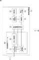
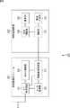
図1の例において、通信システム101は、アンテナ111および情報処理装置112を含むように構成されている。 In the example of FIG. 1, the
アンテナ111は、情報処理装置112に設けられており、図示せぬ無線アクセスポイントと情報処理装置112との間における無線信号の送受信を行う。 The
情報処理装置112は、例えば、ノート型パーソナルコンピュータ、タブレット端末、または、スマートフォンと呼ばれる多機能携帯電話機などである。情報処理装置112は、無線通信モジュール121、無線通信制御部122、制御部123、表示制御部124、表示部125、および操作入力部126を含むように構成されている。 The
無線通信モジュール121は、無線アクセスポイントを介して、他の情報処理装置などと無線通信を行うために、情報処理装置112に内蔵されているモジュールである。無線通信モジュール121は、無線通信制御部122の制御のもと、アンテナ111を介し、図示せぬ無線アクセスポイントを通信対象(ターゲット)として、無線信号の送受信を行う。 The
無線通信モジュール121は、RF送受信部131、A/D(Analog/Digital)変換部132、およびMAC(Media Access Control)制御部133を含むように構成されている。 The
RF送受信部131は、無線通信制御部122の制御のもと、無線通信制御部122により設定された周波数帯域(幅)で、無線信号を送受信する。RF送受信部131は、無線信号を受信した場合、受信した無線信号を、A/D変換部132に供給する。 The RF transmission /
A/D変換部132は、RF送受信部131からのアナログの無線信号をデジタル信号に変換し、変換したデジタル信号を、無線通信制御部122に供給する。 The A /
MAC制御部133は、無線通信制御部122により設定された周波数帯域の各チャンネルと呼ばれる周波数帯(以下、単にチャンネルと称する)に対し、RF送受信部131を介して、アクティブスキャンを行う。すなわち、MAC制御部133は、RF送受信部131を介して、プローブリクエストを送出し、プローブリクエストを受けた無線アクセスポイントが、そのアクセスポイントの情報を返してくる。MAC制御部133は、アクティブスキャンにより無線アクセスポイントが検知された場合、そのアクセスポイントの情報を、RF送受信部131を介して受信し、無線通信制御部122に供給する。 The
無線通信制御部122は、無線通信モジュール121の、複数の周波数帯からなる周波数帯域を設定し、設定した周波数帯域で、RF送受信部131を用いて、無線信号の有無と信号強度とを確認する。無線通信モジュール121においては、最初、規格において使用可能である最も広帯域の周波数帯域が設定されて、無線信号の有無と信号強度との確認処理が行われる。なお、それよりも狭い周波数帯域がある場合、次に広い周波数帯域が設定されて、無線信号の有無と信号強度との確認処理が行われる。 The wireless
設定した周波数帯域に無線信号がある場合、その無線信号は、RF送受信部131により受信され、A/D変換部132によりデジタル信号に変換されて、無線通信制御部122に供給される。無線通信制御部122は、A/D変換部132から供給されたデジタル信号を用いて、該当する周波数帯域の無線信号の有無と信号強度とを確認する。 When there is a radio signal in the set frequency band, the radio signal is received by the RF transmission /
無線通信制御部122は、MAC制御部133を制御し、信号強度が1番強い周波数帯域の各チャンネルから、アクティブスキャンを行わせ、その結果得られるアクセスポイントの情報を制御部123に供給する。 The wireless
制御部123は、設定された周波数帯域での無線通信制御部122からのアクセスポイントの情報を表示制御部124に供給し、アクセスポイントのリストの表示制御を行わせる。また、制御部123は、ユーザによる操作入力部126の操作に対応するアクセスポイントの情報を、無線通信制御部122に供給する。 The
表示制御部124は、制御部123の制御のもと、無線通信制御部122からのアクセスポイントの情報を用いて、アクセスポイントのリストを表示部125に表示させる。 The
表示部125は、LCD(Liquid Crystal Display)などで構成され、表示制御部124からのアクセスポイントのリストを表示する。操作入力部126は、タッチパネルやボタンなどで構成され、ユーザの操作に対応する信号を制御部123に供給する。 The
[周波数帯と周波数帯域]
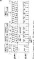
図2は、無線LANで使用される周波数帯と周波数帯域(周波数帯幅)について説明する図である。[Frequency band and frequency band]
FIG. 2 is a diagram illustrating a frequency band and a frequency band (frequency band width) used in the wireless LAN.
IEEE802.11n方式において、2.4GHz帯は、2.4GHz乃至2.4835GHzであり、DFS(dynamic frequency selection)およびTPC(transmitter power control)不要で、屋内外で使用可能な周波数帯域である。 In the IEEE802.11n system, the 2.4 GHz band is 2.4 GHz to 2.4835 GHz, and is a frequency band that can be used indoors and outdoors without the need for DFS (dynamic frequency selection) and TPC (transmitter power control).
2.4GHz帯において、20MHz幅のオペレーションを電波の干渉が起こらないように行う場合、1ch乃至13chのうち、1ch、6ch、および11chを中心とした各20MHzの帯域を利用することが一般的である。なお、1chは、5MHz刻みとなっている。また、2.4GHz帯において、40MHz幅のオペレーションを電波の干渉が起こらないように行う場合、1ch乃至13chのうち、例えば、1+3chで40MHzの利用帯域、および11chを中心とした40MHzの利用帯域といったチャンネル配置となる。 In the 2.4 GHz band, when 20 MHz wide operation is performed so that radio wave interference does not occur, it is common to use each 20 MHz band centering on 1ch, 6ch, and 11ch out of 1ch to 13ch. . 1ch is in 5MHz increments. In addition, in the 2.4 GHz band, when performing operations with a 40 MHz width so that radio wave interference does not occur, among
一方、IEEE802.11n方式においては、5GHz帯のうち、5.15GHz乃至5.25GHzの周波数帯域であるW52タイプ、5.25GHz乃至5.35GHzの周波数帯域であるW53タイプ、および、5.457GHz乃至5.725GHzの周波数帯域であるW56タイプが使用可能である。5.35GHz乃至5.457GHzの周波数帯域は、現在不使用となっている。 On the other hand, in the IEEE802.11n system, of the 5 GHz band, the W52 type that is a frequency band from 5.15 GHz to 5.25 GHz, the W53 type that is a frequency band from 5.25 GHz to 5.35 GHz, and the frequency band from 5.457 GHz to 5.725 GHz. W56 type that is can be used. The frequency band from 5.35 GHz to 5.457 GHz is currently unused.
W52タイプは、DFSおよびTPC不要で、屋内でのみ使用可能な周波数帯域である。W52タイプにおいて、20MHz幅のオペレーションは、36ch、40ch、44ch、および48chを中心とした各20MHzの利用帯域で行われる。また、W52タイプにおいて、40MHz幅のオペレーションは、36+40ch、および44+48chを中心とした各40MHzの利用帯域で行われる。 The W52 type does not require DFS and TPC and is a frequency band that can only be used indoors. In the W52 type, a 20 MHz wide operation is performed in each 20 MHz use band centering on 36 ch, 40 ch, 44 ch, and 48 ch. In the W52 type, a 40 MHz wide operation is performed in each 40 MHz use band centering on 36 + 40 ch and 44 + 48 ch.
W53タイプは、DFSおよびTPC必要で、屋内でのみ使用可能な周波数帯域である。W53タイプにおいて、20MHz幅のオペレーションは、52ch、56ch、60ch、および64chを中心とした各20MHzの利用帯域で行われる。また、W53タイプにおいて、40MHz幅のオペレーションは、52+56ch、および60+64chを中心とした各40MHzの利用帯域で行われる。 The W53 type requires DFS and TPC and is a frequency band that can only be used indoors. In the W53 type, a 20 MHz wide operation is performed in each 20 MHz use band centering on 52ch, 56ch, 60ch, and 64ch. In the W53 type, a 40 MHz wide operation is performed in each 40 MHz use band centering on 52 + 56 ch and 60 + 64 ch.
W56タイプは、DFSおよびTPC必要で、屋内外で使用可能な周波数帯域である。W56タイプにおいて、20MHz幅のオペレーションは、100ch、104ch、108ch、112ch、116ch、120ch、124ch、128ch、132ch、136ch、および140chを中心とした各20MHzの利用帯域で行われる。また、W56タイプにおいて、40MHz幅のオペレーションは、100+104ch、108+112ch、116+120ch、124+128ch、132+136ch、および140chを中心とした各40MHzの利用帯域で行われる。 The W56 type requires DFS and TPC and is a frequency band that can be used indoors and outdoors. In the W56 type, operations of 20 MHz width are performed in each 20 MHz use band centering on 100 ch, 104 ch, 108 ch, 112 ch, 116 ch, 120 ch, 124 ch, 128 ch, 132 ch, 136 ch, and 140 ch. In the W56 type, operation of 40 MHz width is performed in each 40 MHz use band centering on 100 + 104 ch, 108 + 112 ch, 116 + 120 ch, 124 + 128 ch, 132 + 136 ch, and 140 ch.
なお、W53タイプとW56タイプは、日本と欧州とでは、DFSおよびTPCが必要であるが、米国では、DFS のみが必要となっている。また、W56タイプのうち、120ch、124ch、および128chは、日本と欧州とでは、使用可能であるが、米国においては使用不可となっている。 The W53 type and W56 type require DFS and TPC in Japan and Europe, but only DFS is required in the United States. Of the W56 types, 120ch, 124ch, and 128ch can be used in Japan and Europe, but not in the United States.
以上のように、IEEE802.11n方式の普及により、従来からの802.11a/b/g方式の20MHzの周波数帯域を使用する方式に加え、40MHzの周波数帯域を使用することが可能になってきている。 As described above, with the widespread use of the IEEE802.11n system, it is now possible to use the 40 MHz frequency band in addition to the conventional 802.11a / b / g system 20 MHz frequency band. .
本技術においては、これを利用して、以下に説明するように、通信対象である、無線LANアクセスポイントの検索の高速化を図る。 In the present technology, as described below, this technique is used to speed up the search for the wireless LAN access point that is the communication target.
[2.4GHz帯の例]
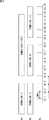
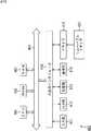
図3の例においては、通信システム101が行う2.4GHzの場合の無線LANアクセスポイントの検索手順が示されている。[Example of 2.4GHz band]
In the example of FIG. 3, a wireless LAN access point search procedure in the case of 2.4 GHz performed by the
2.4GHzの場合、無線通信制御部122は、まず、A1に示されるように、無線通信モジュール121の周波数帯域のモードを、ch.1を中心周波数帯とした20MHzモード(20MHz(ch.1))に設定する。すなわち、ch.1を中心周波数帯とした20MHzモード(20MHz(ch.1))においては、ch.1を中心周波数帯とした20MHz帯域が連続して使用される。無線通信制御部122は、設定した周波数帯域20MHz(ch.1)で、RF送受信部131を用いて、無線信号の有無と信号強度とを確認する。これにより、ch.1乃至ch.3の周波数帯域の無線信号の有無と信号強度とが確認される。 In the case of 2.4 GHz, the wireless
また、無線通信制御部122は、無線通信モジュール121の周波数帯域モードを、Ch.6とCh.10とを中心周波数帯とした40MHzモード(40MHz(ch.6+ch.10))に設定する。すなわち、Ch.6とCh.10とを中心周波数帯とした40MHzモード(40MHz(ch.6+ch.10))においては、Ch.6とCh.10とを中心周波数帯とした40MHz帯域が連続して使用される。 Further, the wireless
なお、A2に示されるように、20MHzモードの場合、お互いが干渉しないように、ch.1中心、Ch.6中心、ch.11中心の各周波数帯域の間に、空白(ガードバンド)がある。これに対して、40MHzモードで40MHz帯域を連続して使用する際には、A1に示されるように、Ch.6中心の周波数帯域とCh.11中心の周波数帯域との間の空白が詰めて使用されるので、中心周波数帯が1チャンネルずれてCh.10となる。よって、40MHzモードの場合は、6ch+10ch(÷2=ch.8)を中心に、Ch.4乃至Ch.12を占有することとなる。 As shown in A2, in the 20 MHz mode, there is a blank (guard band) between the frequency bands of the ch.1 center, Ch.6 center, and ch.11 center so that they do not interfere with each other. . On the other hand, when the 40 MHz band is continuously used in the 40 MHz mode, as shown in A1, the space between the Ch.6 center frequency band and the Ch.11 center frequency band is filled. Because it is used, the center frequency band is shifted by 1 channel to Ch.10. Therefore, in the 40 MHz mode, Ch.4 to Ch.12 are occupied centering on 6ch + 10ch (÷ 2 = ch.8).
無線通信制御部122は、設定した周波数帯域40MHz(ch.6+ch.10)で、RF送受信部131を用いて、無線信号の有無と信号強度とを確認する。これにより、ch.4乃至ch.12の周波数帯域の無線信号の有無と信号強度とが確認される。 The wireless
ここで、ch.1を中心周波数帯とした40MHzモードとせずに、ch.1を中心周波数帯とした20MHzモードとしたのは、現状、ch.1がアクセスポイントとして使用されることが多いためである。 Here, instead of using the 40MHz mode with ch.1 as the center frequency band, the 20MHz mode with ch.1 as the center frequency band is used because ch.1 is often used as an access point at present. It is.
次に、無線通信制御部122は、A2に示されるように、無線通信モジュール121の周波数帯域のモードを、ch.6を中心周波数帯とした20MHzモード(20MHz(ch.6))に設定する。すなわち、ch.6を中心周波数帯とした20MHzモード(20MHz(ch.6))においては、ch.6を中心周波数帯とした20MHz帯域が連続して使用される。無線通信制御部122は、設定した周波数帯域20MHz(ch.6)で、RF送受信部131を用いて、無線信号の有無と信号強度とを確認する。これにより、ch.4乃至ch.8の周波数帯域の無線信号の有無と信号強度とが確認される。 Next, as shown in A2, the wireless
また、無線通信制御部122は、無線通信モジュール121の周波数帯域のモードを、ch.11を中心周波数帯とした20MHzモード(20MHz(ch.11))に設定する。ch.11を中心周波数帯とした20MHzモード(20MHz(ch.11))すなわち、ch.11を中心周波数帯とした20MHzモード(20MHz(ch.11))においては、ch.11を中心周波数帯とした20MHz帯域が連続して使用される。無線通信制御部122は、RF送受信部131を用いて、無線信号の有無と信号強度とを確認する。これにより、ch.9乃至ch.13の周波数帯域の無線信号の有無と信号強度とが確認される。 Further, the wireless
無線通信制御部122は、ここで、20MHz(ch.1)、20MHz(ch.6)、および20MHz(ch.11)の信号強度を比較し、最も信号強度のモードの各チャンネルのアクティブスキャンを開始する。 Here, the wireless
例えば、20MHz(ch.1)の信号強度が最も強い場合、A3に示されるように、20MHz(ch.1)の周波数帯域のch.1、ch.2、ch.3の各チャンネルのアクティブスキャンが行われる。アクティブスキャンの結果により、アクセスポイントが検知され、ユーザに提示されるが、検知されたアクセスポイントがユーザに選択されない場合には、次に信号強度が強い周波数帯域の各チャンネルのアクティブスキャンが行われる。 For example, when the signal strength of 20MHz (ch.1) is the strongest, as shown in A3, the active scan of each channel of ch.1, ch.2, ch.3 in the frequency band of 20MHz (ch.1) Is done. Depending on the result of the active scan, an access point is detected and presented to the user. If the detected access point is not selected by the user, an active scan is performed for each channel in the frequency band with the next highest signal strength. .
なお、A1の後に、20MHz(ch.1)および40MHz(ch.6+ch.10)の信号強度を比較して、20MHz(ch.1)の信号強度が強い場合には、A2の処理をスキップして、A3のように、アクティブスキャンを行うようにしてもよい。 Compare the signal strength of 20MHz (ch.1) and 40MHz (ch.6 + ch.10) after A1, and if the signal strength of 20MHz (ch.1) is strong, the processing of A2 is skipped. Thus, active scan may be performed as in A3.
例えば、次に信号強度が強い周波数帯域が20MHz(ch.6)の場合、A3に示されるように、20MHz(ch.6)の周波数帯域のch.6、ch.5、ch.7、ch.4、ch.8の各チャンネルのアクティブスキャンが行われる。アクティブスキャンの結果により、アクセスポイントが検知され、ユーザに提示されるが、検知されたアクセスポイントがユーザに選択されない場合には、次に信号強度が強い周波数帯域の各チャンネルのアクティブスキャンが行われる。 For example, if the frequency band with the next strongest signal strength is 20 MHz (ch.6), as shown in A3, the frequency band of 20 MHz (ch.6) is ch.6, ch.5, ch.7, ch. Active scan of each channel of .4 and ch.8 is performed. Depending on the result of the active scan, an access point is detected and presented to the user. If the detected access point is not selected by the user, an active scan is performed for each channel in the frequency band with the next highest signal strength. .
例えば、次に信号強度が強い周波数帯域が20MHz(ch.11)の場合、A3に示されるように、20MHz(ch.11)の周波数帯域のch.11、ch.10、ch.12、ch.9、ch.13の各チャンネルのアクティブスキャンが行われる。アクティブスキャンの結果により、アクセスポイントが検知され、ユーザに提示されるが、検知されたアクセスポイントがユーザに選択されない場合には、処理は終了する。 For example, when the frequency band with the next strongest signal strength is 20 MHz (ch.11), as shown in A3, ch.11, ch.10, ch.12, ch. .9, ch.13 channel active scan is performed. According to the result of the active scan, the access point is detected and presented to the user. However, when the detected access point is not selected by the user, the process ends.
なお、上述したように、各周波数帯域においては、中心となる周波数帯(ch.1、ch.6、ch.11)からアクティブスキャンが行われるが、その後の順は限定されない。 As described above, in each frequency band, active scanning is performed from the central frequency band (ch.1, ch.6, ch.11), but the subsequent order is not limited.
[5GHz帯の例]
図4の例においては、通信システム101が行う5GHzの場合の無線LANアクセスポイントの検索手順が示されている。なお、802.11ac方式では、80MHzモードの使用が可能である。したがって、802.11ac方式が利用可能となった場合には、5GHzの場合、B1に示されるように、無線通信モジュール121の周波数帯域のモードを80MHzモードに設定して、2.4GHzモードと同様な検索手順を行うことが可能である。[Example of 5 GHz band]
In the example of FIG. 4, a wireless LAN access point search procedure in the case of 5 GHz performed by the
5GHzの場合、無線通信制御部122は、まず、B2に示されるように、無線通信モジュール121の周波数帯域のモードを、ch.36およびCh.40を中心周波数帯とした40MHzモード(40MHz(ch.36&ch.40))に設定する。すなわち、ch.36およびCh.40を中心周波数帯とした40MHzモード(40MHz(ch.36&ch.40))においては、ch.36およびCh.40を中心周波数帯とした40MHz帯域が連続して使用される。無線通信制御部122は、設定した周波数帯域40MHz(ch.36&ch.40)で、RF送受信部131を用いて、無線信号の有無と信号強度とを確認する。 In the case of 5 GHz, first, as shown in B2, the radio
また、無線通信制御部122は、無線通信モジュール121の周波数帯域のモードを、ch.44およびCh.48を中心周波数帯とした40MHzモード(40MHz(ch.44&ch.48))に設定する。すなわち、ch.44およびCh.48を中心周波数帯とした40MHzモード(40MHz(ch.44&ch.48))においては、ch.44およびCh.48を中心周波数帯とした40MHz帯域が連続して使用される。無線通信制御部122は、設定した周波数帯域40MHz(ch.44&ch.48)で、RF送受信部131を用いて、無線信号の有無と信号強度とを確認する。 Further, the wireless
Ch.52以降、同様に、無線通信モジュール121の周波数帯域のモードが、該当する周波数帯を中心周波数帯とした40MHz帯域を連続して使用する40MHzモードに設定されて、そのモードでの無線信号の有無と信号強度との確認処理が行われる。その後、無線通信制御部122は、40MHz(ch.36&ch.40)、40MHz(ch.44&ch.48)、…の信号強度を比較し、最も信号強度の強いモードの各チャンネルのアクティブスキャンを開始する。これは、一般的に、無線LAN接続を行いたいアクセスポイントは、一番近傍のものであり、一番近傍のものは、同時信号強度が強いことを意味するからである。 After Ch. 52, similarly, the frequency band mode of the
例えば、40MHz(ch.36&ch.40)の信号強度が最も強い場合、B3に示されるように、ch.36、ch.40の各チャンネルのアクティブスキャンが行われる。アクティブスキャンの結果により、アクセスポイントが検知され、ユーザに提示されるが、検知されたアクセスポイントがユーザに選択されない場合には、次に信号強度が強い周波数帯域の各チャンネルのアクティブスキャンが行われる。 For example, when the signal intensity of 40 MHz (ch.36 & ch.40) is the strongest, as shown in B3, the active scan of each channel of ch.36 and ch.40 is performed. Depending on the result of the active scan, an access point is detected and presented to the user. If the detected access point is not selected by the user, an active scan is performed for each channel in the frequency band with the next highest signal strength. .
以上のように、通信システム101においては、各チャンネル(周波数帯)のアクティブスキャンの前に、すなわち、論理的な情報の処理を行う前に、複数チャンネルを含む広帯域周波数のグループ(域)で無線信号の有無と信号強度とが確認される。そして、信号強度が比較され、信号強度の強いグループのチャンネルからアクティブスキャンが行われる。 As described above, in the
これにより、無線LANのアクセスポイントの検索が高速化されるので、例えば、高機能携帯電話機やタブレット端末、ノート型パーソナルコンピュータなど、無線通信を行う装置の利便性が高まる。 This speeds up the search for the access point of the wireless LAN, so that the convenience of a device that performs wireless communication, such as a high-function mobile phone, a tablet terminal, or a notebook personal computer, is enhanced.
[2.4GHz帯の場合の動作]
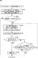
次に、図5のフローチャートを参照して、通信システム101における2.4GHz帯の場合のアクセスポイントの検索処理について説明する。[Operation in 2.4GHz band]
Next, access point search processing in the 2.4 GHz band in the
ステップS111において、無線通信制御部122は、無線通信モジュール121の周波数帯域のモードを、2.4MHz、ch.1を中心周波数帯とした20MHzモード(20MHz(ch.1))に設定する。そして、無線通信制御部122は、設定した周波数帯域で、RF送受信部131を用いて、無線信号の有無と信号強度とを確認する。 In step S111, the wireless
ステップS112において、無線通信制御部122は、無線通信モジュール121の周波数帯域のモードを、2.4MHz、Ch.6とCh.10とを中心周波数帯とした40MHzモード(40MHz(ch.6+ch.10))に設定する。無線通信制御部122は、設定した周波数帯域で、RF送受信部131を用いて、無線信号の有無と信号強度とを確認する。 In step S112, the wireless
RF送受信部131は、無線信号を受信した場合、受信した無線信号を、A/D変換部132に供給する。A/D変換部132は、RF送受信部131からのアナログの無線信号をデジタル信号に変換し、変換したデジタル信号を無線通信制御部122に供給する。 When receiving the radio signal, the RF transmission /
ステップS113において、無線通信制御部122は、A/D変換部132からのデジタル信号を参照して、20MHz(Ch.1)の周波数帯域と40MHz(CH.6+Ch.11)の周波数帯域に、無線信号が存在したか否かを判定する。ステップS113において、無線信号が存在していないと判定された場合、このアクセスポイントの検索処理は終了される。 In step S113, the wireless
一方、ステップS113において、無線信号が存在すると判定された場合、処理は、ステップS114に進む。 On the other hand, if it is determined in step S113 that a wireless signal exists, the process proceeds to step S114.
ステップS114において、無線通信制御部122は、20MHz(Ch.1)の周波数帯域のほうが、40MHz(CH.6+Ch.11)の周波数帯域より信号強度が強いか否かを判定する。ステップS114において、20MHz(Ch.1)の周波数帯域のほうが、信号強度が強いと判定された場合、処理は、ステップS115に進む。 In step S114, the radio
ステップS115において、無線通信制御部122は、MAC制御部133に、20MHz(Ch.1)の周波数帯域の各チャンネルに対してアクティブスキャンを行わせる。すなわち、MAC制御部133は、RF送受信部131を介して、各チャンネル(周波数帯)に対して、プローブリクエストを送出し、プローブリクエストを受けた無線アクセスポイントが、そのアクセスポイントの情報を返してくる。 In step S115, the wireless
例えば、中心周波数Ch.1からアクティブスキャンが行われる。Ch.1の後は、Ch.2の処理であってもよいし、Ch.3の処理であってもよい。 For example, active scan is performed from the center frequency Ch. After Ch.1, the processing of Ch.2 may be performed or the processing of Ch.3 may be performed.
MAC制御部133は、アクティブスキャンにより、無線アクセスポイントが検知された場合、そのアクセスポイントの情報を、無線通信制御部122に供給する。このアクセスポイントの情報は、少なくとも、アクセスポイントの表示名を含み、制御部123を介して、表示制御部124に供給される。 When a wireless access point is detected by active scanning, the
ステップS116において、表示制御部124は、アクセスポイントのリストを表示部125に表示させ、ユーザに提示する。 In step S116, the
なお、実際には、このステップS115およびS116の処理は、チャンネル毎に行われる。すなわち、ステップS115において、各チャンネルでのスキャンが終了する度にすぐに、ステップS116において、アクセスポイントのリストがユーザに提示される。これにより、ユーザができるたけ速やかに目的のアクセスポイントを発見できるようにする。 Actually, the processes in steps S115 and S116 are performed for each channel. That is, in step S115, as soon as scanning on each channel is completed, a list of access points is presented to the user in step S116. This enables the user to find the target access point as quickly as possible.
表示部125に表示されるアクセスポイントのリストを見て、目的のアクセスポイント名があった場合、ユーザは、操作入力部126を操作して、そのアクセスポイントを選択する。操作入力部126は、ユーザの操作に対応する信号を、制御部123に供給する。 By looking at the list of access points displayed on the
ステップS117において、制御部123は、操作入力部126より供給される信号を参照して、ユーザによるアクセスポイントの選択があるか否かを判定する。ステップS117において、制御部123は、ユーザによるアクセスポイントの選択があると判定した場合、ユーザにより選択されたアクセスポイントの情報を、無線通信制御部122に供給し、処理は、ステップS118に進む。 In step S117, the
ステップS118において、無線通信制御部122は、MAC制御部133を制御し、ユーザが選択したアクセスポイントと情報処理装置112とを接続させる。この後、アクセスポイント検索処理は終了される。 In step S118, the wireless
一方、ステップS114において、40MHz(CH.6+Ch.10)の周波数帯域の方が、信号強度が強いと判定された場合、処理は、ステップS119に進む。また、ステップS117において、制御部123によりユーザによるアクセスポイントの選択がないと判定された場合、処理は、ステップS119に進む。 On the other hand, if it is determined in step S114 that the signal frequency is stronger in the 40 MHz (CH.6 + Ch.10) frequency band, the process proceeds to step S119. If the
ステップS119において、無線通信制御部122は、無線通信モジュール121の周波数帯域のモードを、2.4MHz、20MHz(CH.6)および20MHz (Ch.11)にそれぞれ設定する。無線通信制御部122は、設定した周波数帯域毎に、RF送受信部131を用いて、無線信号の有無と信号強度とを確認する。 In step S119, the wireless
RF送受信部131は、無線信号を受信した場合、受信した無線信号を、A/D変換部132に供給する。A/D変換部132は、RF送受信部131からのアナログの無線信号をデジタル信号に変換し、変換したデジタル信号を無線通信制御部122に供給する。 When receiving the radio signal, the RF transmission /
ステップS120において、無線通信制御部122は、各信号強度を比較し、次に信号強度の強い周波数帯域の各チャンネルに対してアクティブスキャンを行う。 In step S120, the wireless
20MHz(CH.6)の周波数帯域の場合、例えば、中心周波数Ch.6からアクティブスキャンが行われる。Ch.6の後の順は、Ch.4,5,7,8の処理順であってもよいし、Ch.5,6,4,8の処理順であってもよいし、中心周波数以外のスキャンの順は限定されない。 In the case of a frequency band of 20 MHz (CH.6), for example, active scan is performed from the center frequency Ch.6. The order after Ch.6 may be the processing order of Ch.4,5,7,8, the processing order of Ch.5,6,4,8, or other than the center frequency The order of scanning is not limited.
同様に、20MHz(CH.11)の周波数帯域の場合、例えば、中心周波数Ch.11からアクティブスキャンが行われる。Ch.11の後の順は、Ch.9,10,12,13であってもよいし、Ch.10,12,9,13の処理であってもよいし、中心周波数以外のスキャンの順は限定されない。 Similarly, in the case of a frequency band of 20 MHz (CH.11), for example, active scanning is performed from the center frequency Ch.11. The order after Ch.11 may be Ch.9,10,12,13, Ch.10,12,9,13, or scan order other than the center frequency. Is not limited.
MAC制御部133は、アクティブスキャンにより、無線アクセスポイントが検知された場合、そのアクセスポイントの情報を、無線通信制御部122に供給する。このアクセスポイントの情報は、少なくとも、アクセスポイントの表示名を含み、制御部123を介して、表示制御部124に供給される。 When a wireless access point is detected by active scanning, the
ステップS121において、表示制御部124は、アクセスポイントのリストを表示部125に表示させ、ユーザに提示する。 In step S121, the
なお、実際には、このステップS121およびS122の処理は、ステップS115およびS116の処理と基本的に同様であり、チャンネル毎に行われる。すなわち、ステップS121において、各チャンネルでのスキャンが終了する度にすぐに、ステップS122において、アクセスポイントのリストがユーザに提示される。これにより、ユーザができるたけ速やかに目的のアクセスポイントを発見できるようにする。 In practice, the processes in steps S121 and S122 are basically the same as the processes in steps S115 and S116, and are performed for each channel. That is, in step S121, as soon as scanning on each channel is completed, a list of access points is presented to the user in step S122. This enables the user to find the target access point as quickly as possible.
表示部125に表示されるアクセスポイントのリストを見て、目的のアクセスポイント名があった場合、ユーザは、操作入力部126を操作して、そのアクセスポイントを選択する。操作入力部126は、ユーザの操作に対応する信号を、制御部123に供給する。 By looking at the list of access points displayed on the
ステップS122において、制御部123は、操作入力部126より供給される信号を参照して、ユーザによるアクセスポイントの選択があるか否かを判定する。ステップS122において、制御部123は、ユーザによるアクセスポイントの選択があると判定した場合、ユーザにより選択されたアクセスポイントの情報を、無線通信制御部122に供給し、処理は、ステップS118に進む。 In step S122, the
ステップS122において、ユーザによるアクセスポイントの選択がないと判定された場合、処理は、ステップS123に進む。ステップS123において、無線通信制御部122は、すべての周波数帯域に対するアクティブスキャンが終了したか否かを判定する。 If it is determined in step S122 that the user has not selected an access point, the process proceeds to step S123. In step S123, the wireless
ステップS123において、まだ、すべての周波数帯域におけるアクティブスキャンがまだ終わっていない場合、処理は、ステップS120に戻り、それ以降の処理が繰り返される。 In step S123, when active scanning in all frequency bands has not yet been completed, the processing returns to step S120, and the subsequent processing is repeated.
ステップS123において、すべてのグループの周波数帯域に対するアクティブスキャンが終わったと判定した場合、このアクセスポイントの検索処理は終了される。 If it is determined in step S123 that the active scan for the frequency bands of all groups has been completed, the access point search process is terminated.
なお、図5の例においては、リストをユーザに提示した後、ユーザによる選択がないと判定された場合に、次の周波数帯域の処理(信号強度の確認またはアクティブスキャン)を行う例を説明したが、この例に限らない。例えば、リストを表示する画面に、次のアクセスポイントのリスト表示のボタンなどを設け、ユーザによりそのボタンが押された場合に、すぐに、次の周波数帯域の処理を行うようにしてもよい。 In the example of FIG. 5, after the list is presented to the user, when it is determined that there is no selection by the user, an example in which processing of the next frequency band (confirmation of signal intensity or active scan) is performed has been described. However, it is not limited to this example. For example, a list display button for the next access point may be provided on the screen for displaying the list, and when the user presses the button, processing for the next frequency band may be performed immediately.
[5GHz帯の場合の動作]
次に、図6のフローチャートを参照して、通信システム101における5GHz帯の場合のアクセスポイントの検索処理について説明する。[Operation for 5 GHz band]
Next, access point search processing in the case of the 5 GHz band in the
ステップS151において、無線通信制御部122は、無線通信モジュール121の周波数帯域のモードを、5GHz、40MHzモードに設定し、設定した40MHzの周波数帯域毎に、RF送受信部131を用いて、無線信号の有無と信号強度とを確認する。 In step S151, the wireless
RF送受信部131は、無線信号を受信した場合、受信した無線信号を、A/D変換部132に供給する。A/D変換部132は、RF送受信部131からのアナログの無線信号をデジタル信号に変換し、変換したデジタル信号を無線通信制御部122に供給する。 When receiving the radio signal, the RF transmission /
ステップS152において、無線通信制御部122は、A/D変換部132からのデジタル信号を参照して、各周波数帯域に無線信号が存在したか否かを判定する。ステップS152において、すべての周波数帯域に無線信号が存在していないと判定された場合、このアクセスポイントの検索処理は終了される。 In step S152, the wireless
一方、ステップS152において、無線信号が存在すると判定された場合、処理は、ステップS153に進む。 On the other hand, if it is determined in step S152 that a wireless signal exists, the process proceeds to step S153.
ステップS153において、無線通信制御部122は、各周波数帯域の信号強度を比較し、次に信号強度の強い周波数帯域の各チャンネルに対してアクティブスキャンを行う。例えば、5GHz、40MHzモードの場合、40MHzの周波数帯域には、2つのチャンネルが含まれており、それらのチャンネルに対して順にアクティブスキャンが行われる。 In step S153, the wireless
すなわち、MAC制御部133は、RF送受信部131を介して、各チャンネル(周波数帯)に対して、プローブリクエストを送出し、プローブリクエストを受けた無線アクセスポイントが、そのアクセスポイントの情報を返してくる。 That is, the
MAC制御部133は、アクティブスキャンにより、無線アクセスポイントが検知された場合、そのアクセスポイントの情報を、無線通信制御部122に供給する。このアクセスポイントの情報は、少なくとも、アクセスポイントの表示名を含み、制御部123を介して、表示制御部124に供給される。 When a wireless access point is detected by active scanning, the
ステップS154において、表示制御部124は、アクセスポイントのリストを表示部125に表示させ、ユーザに提示する。 In step S154, the
なお、実際には、このステップS153およびS154の処理は、図5のステップS115およびS116の処理と基本的に同様であり、チャンネル毎に行われる。すなわち、ステップS153において、各チャンネルでのスキャンが終了する度にすぐに、ステップS154において、アクセスポイントのリストがユーザに提示される。これにより、ユーザができるたけ速やかに目的のアクセスポイントを発見できるようにする。 In practice, the processes in steps S153 and S154 are basically the same as the processes in steps S115 and S116 in FIG. 5, and are performed for each channel. That is, in step S153, every time scanning on each channel is completed, a list of access points is presented to the user in step S154. This enables the user to find the target access point as quickly as possible.
表示部125に表示されるアクセスポイントのリストを見て、目的のアクセスポイント名があった場合、ユーザは、操作入力部126を操作して、そのアクセスポイントを選択する。操作入力部126は、ユーザの操作に対応する信号を、制御部123に供給する。 By looking at the list of access points displayed on the
ステップS155において、制御部123は、操作入力部126より供給される信号を参照して、ユーザによるアクセスポイントの選択があるか否かを判定する。ステップS155において、制御部123は、ユーザによるアクセスポイントの選択があると判定した場合、ユーザにより選択されたアクセスポイントの情報を、無線通信制御部122に供給し、処理は、ステップS156に進む。 In step S155, the
ステップS156において、無線通信制御部122は、MAC制御部133を制御し、ユーザが選択したアクセスポイントと情報処理装置112とを接続させる。この後、アクセスポイント検索処理は終了される。 In step S156, the wireless
ステップS155において、ユーザによるアクセスポイントの選択がないと判定された場合、処理は、ステップS157に進む。ステップS157において、無線通信制御部122は、すべての40MHzの周波数帯域の各チャンネルに対するアクティブスキャンが終了したか否かを判定する。 If it is determined in step S155 that the user has not selected an access point, the process proceeds to step S157. In step S157, the wireless
ステップS123において、まだ、すべての周波数帯域の各チャンネルに対するアクティブスキャンがまだ終わっていない場合、処理は、ステップS153に戻り、それ以降の処理が繰り返される。 In step S123, when the active scan for each channel in all frequency bands has not been completed yet, the process returns to step S153, and the subsequent processes are repeated.
ステップS123において、すべての周波数帯域の各チャンネルに対するアクティブスキャンが終わったと判定した場合、このアクセスポイントの検索処理は終了される。 If it is determined in step S123 that the active scan has been completed for each channel in all frequency bands, the access point search process is terminated.
以上のように、通信システム101においては、各チャンネル(周波数帯)に対して論理的な情報の処理を行う前に、複数チャンネルを含む広帯域周波数のグループ(域)で無線信号の有無と信号強度とが確認される。そして、信号強度が比較され、信号強度の強いグループのチャンネルからアクティブスキャンが行われる。 As described above, in the
これにより、無線LANのアクセスポイントの検索が高速化されるので、例えば、高機能携帯電話機やタブレット端末、ノート型パーソナルコンピュータなど、無線通信を行う装置の利便性が高まる。 This speeds up the search for the access point of the wireless LAN, so that the convenience of a device that performs wireless communication, such as a high-function mobile phone, a tablet terminal, or a notebook personal computer, is enhanced.
[本技術の通信システムの他の構成]
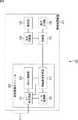
図7は、本技術を適用した通信システムの他の構成例を示す図である。[Other configurations of the communication system of the present technology]
FIG. 7 is a diagram illustrating another configuration example of the communication system to which the present technology is applied.
図7の例において、通信システム201は、アンテナ111、無線通信モジュール211、および情報処理装置212を含むように構成されている。 In the example of FIG. 7, the
無線通信モジュール211は、情報処理装置212の外に着脱可能に設けられている点のみが、図1の無線通信モジュール121と異なる。無線通信モジュール211は、RF送受信部131、A/D変換部132、およびMAC制御部133を含むように構成されている点が、図1の無線通信モジュール121と共通している。 The
情報処理装置212は、無線通信モジュール121が除かれた点のみが、図1の情報処理装置112と異なる。情報処理装置212は、無線通信制御部122、制御部123、表示制御部124、表示部125、および操作入力部126を含むように構成されている点が、図1の情報処理装置112と共通している。 The
すなわち、図1の通信システム101は、無線通信モジュール121が情報処理装置112に内蔵されていたが、図7の通信システム201においては、無線通信モジュール211が、情報処理装置212に着脱可能に構成されている。 That is, in the
したがって、図2の通信システム201は、図1の通信システム101と基本的に同様の処理を行うため、その説明は繰り返しになるので省略される。 Therefore, the
以上のように、通信システム201は、無線通信モジュール211が情報処理装置212に外付けされている。このように構成される通信システム201においても、図1の通信システム101と同様に、各チャンネル(周波数帯)のアクティブスキャンの前に、複数チャンネルを含む広帯域周波数のグループ(域)で無線信号の有無と信号強度とが確認される。そして、信号強度が比較され、信号強度の強いグループのチャンネルからアクティブスキャンが行われる。 As described above, in the
これにより、無線LANのアクセスポイントの検索が高速化されるので、例えば、高機能携帯電話機やタブレット端末、ノート型パーソナルコンピュータなど、無線通信を行う装置の利便性が高まる。 This speeds up the search for the access point of the wireless LAN, so that the convenience of a device that performs wireless communication, such as a high-function mobile phone, a tablet terminal, or a notebook personal computer, is enhanced.
[本技術の通信システムの他の構成]
図8は、本技術を適用した通信システムの他の構成例を示す図である。[Other configurations of the communication system of the present technology]
FIG. 8 is a diagram illustrating another configuration example of the communication system to which the present technology is applied.
図8の例において、通信システム251は、アンテナ111、無線通信モジュール261、および情報処理装置262を含むように構成されている。 In the example of FIG. 8, the
無線通信モジュール261は、無線通信制御部271が追加された点のみが、図7の無線通信モジュール211と異なる。無線通信モジュール261は、RF送受信部131、A/D変換部132、およびMAC制御部133を含むように構成されている点が、図7の無線通信モジュール211と共通している。 The
情報処理装置262は、無線通信制御部122が除かれた点のみが、図7の情報処理装置212と異なる。情報処理装置262は、制御部123、表示制御部124、表示部125、および操作入力部126を含むように構成されている点が、図7の情報処理装置212と共通している。 The
なお、無線通信制御部271は、設けられている場所が異なるだけであり、図1および図7の無線通信制御部122と基本的に同様の処理を行う。 Note that the wireless
すなわち、図7の通信システム201においては、無線通信制御部122が情報処理装置212側に設けられていたが、図8の通信システム251においては、無線通信制御部271が、無線通信モジュール261に設けられている。 That is, in the
したがって、図8の通信システム251においては、無線通信モジュール261側に処理負荷がかかるが、行われる処理は、図7の通信システム201(つまりは、図1の通信システム101)と基本的に同様の処理であり、その説明は繰り返しになるので省略される。 Therefore, in the
以上のように、通信システム251は、無線通信モジュール261が情報処理装置262に外付けされており、無線通信モジュール261側に無線通信制御部271が設けられている。このように構成される通信システム251においても、図1の通信システム101と同様に、各チャンネル(周波数帯)のアクティブスキャンの前に、複数チャンネルを含む広帯域周波数のグループ(域)で無線信号の有無と信号強度とが確認される。そして、信号強度が比較され、信号強度の強いグループのチャンネルからアクティブスキャンが行われる。 As described above, in the
これにより、無線LANのアクセスポイントの検索が高速化されるので、例えば、高機能携帯電話機やタブレット端末、ノート型パーソナルコンピュータなど、無線通信を行う装置の利便性が高まる。 This speeds up the search for the access point of the wireless LAN, so that the convenience of a device that performs wireless communication, such as a high-function mobile phone, a tablet terminal, or a notebook personal computer, is enhanced.
[本技術の通信システムの他の構成]
図9は、本技術を適用した通信システムの他の構成例を示す図である。[Other configurations of the communication system of the present technology]
FIG. 9 is a diagram illustrating another configuration example of the communication system to which the present technology is applied.
図9の例において、通信システム301は、アンテナ111および情報処理装置311を含むように構成されている。 In the example of FIG. 9, the
情報処理装置311は、無線通信モジュール121が無線通信モジュール321に入れ替わった点と、無線通信制御部122が除かれた点が、図1の情報処理装置112と異なる。情報処理装置311は、制御部123、表示制御部124、表示部125、および操作入力部126を含むように構成されている点が、図1の情報処理装置112と共通している。 The
無線通信モジュール321は、情報処理装置311に内蔵されている点のみが、図8の無線通信モジュール261と異なる。 The
また、換言するに、無線通信モジュール321は、図8の無線通信制御部271が追加された点のみが、図1の無線通信モジュール121と異なる。無線通信モジュール321は、RF送受信部131、A/D変換部132、およびMAC制御部133を含むように構成されている点が、図1の無線通信モジュール121と共通している。 In other words, the
無線通信制御部271は、図8の無線通信制御部271と同様に、設けられている場所が異なるだけであり、図1および図7の無線通信制御部122と基本的に同様の処理を行う。 Similar to the wireless
すなわち、図1の通信システム101においては、無線通信制御部122が情報処理装置112側に設けられていたが、図9の通信システム301においては、無線通信制御部271が、無線通信モジュール321に設けられている。 That is, in the
したがって、図9の通信システム301においては、無線通信モジュール321側に処理負荷がかかるが、行われる処理は、図1の通信システム101と基本的に同様の処理であり、その説明は繰り返しになるので省略される。 Therefore, in the
以上のように、通信システム301においては、情報処理装置311に内蔵されている無線通信モジュール321側に無線通信制御部271が設けられている。このように構成される通信システム301においても、図1の通信システム101と同様に、各チャンネル(周波数帯)のアクティブスキャンの前に、複数チャンネルを含む広帯域周波数のグループ(域)で無線信号の有無と信号強度とが確認される。そして、信号強度が比較され、信号強度の強いグループのチャンネルからアクティブスキャンが行われる。 As described above, in the
これにより、無線LANのアクセスポイントの検索が高速化されるので、例えば、高機能携帯電話機やタブレット端末、ノート型パーソナルコンピュータなど、無線通信を行う装置の利便性が高まる。 This speeds up the search for the access point of the wireless LAN, so that the convenience of a device that performs wireless communication, such as a high-function mobile phone, a tablet terminal, or a notebook personal computer, is enhanced.
なお、上記説明においては、通信対象として、無線アクセスポイントと通信を行うインフラストラクチャモードでの例を説明したが、本技術の適用範囲は、これに限らない。すなわち、本技術は、通信対象として、クライアントと(すなわち、端末同士で)通信を行うアドホックモードでの通信の場合にも適用することが可能である。 In the above description, an example in the infrastructure mode in which communication with a wireless access point is performed as a communication target has been described, but the scope of application of the present technology is not limited thereto. That is, the present technology can also be applied to communication in an ad hoc mode in which communication is performed with a client (that is, between terminals) as a communication target.
上述した一連の処理は、ハードウエアにより実行することもできるし、ソフトウエアにより実行することもできる。一連の処理をソフトウエアにより実行する場合には、そのソフトウエアを構成するプログラムが、コンピュータにインストールされる。ここで、コンピュータには、専用のハードウエアに組み込まれているコンピュータや、各種のプログラムをインストールすることで、各種の機能を実行することが可能な、例えば汎用のパーソナルコンピュータなどが含まれる。 The series of processes described above can be executed by hardware or can be executed by software. When a series of processing is executed by software, a program constituting the software is installed in the computer. Here, the computer includes, for example, a general-purpose personal computer capable of executing various functions by installing various programs by installing a computer incorporated in dedicated hardware.
[コンピュータの構成例]
図10は、上述した一連の処理をプログラムにより実行するコンピュータのハードウエアの構成例を示している。[Computer configuration example]
FIG. 10 shows an example of the hardware configuration of a computer that executes the above-described series of processing by a program.
コンピュータ400において、CPU(Central Processing Unit)401,ROM(Read Only Memory)402,RAM(Random Access Memory)403は、バス404により相互に接続されている。 In the
バス404には、さらに、入出力インタフェース410が接続されている。入出力インタフェース410には、入力部411、出力部412、記憶部413、通信部414、及びドライブ415が接続されている。 An input /
入力部411は、キーボード、マウス、マイクロホンなどよりなる。出力部412は、ディスプレイ、スピーカなどよりなる。記憶部413は、ハードディスクや不揮発性のメモリなどよりなる。通信部414は、ネットワークインタフェースなどよりなる。ドライブ415は、磁気ディスク、光ディスク、光磁気ディスク、又は半導体メモリなどのリムーバブルメディア421を駆動する。 The
以上のように構成されるコンピュータでは、CPU401が、例えば、記憶部413に記憶されているプログラムを、入出力インタフェース410及びバス404を介して、RAM403にロードして実行することにより、上述した一連の処理が行われる。 In the computer configured as described above, the
コンピュータ(CPU401)が実行するプログラムは、例えば、パッケージメディア等としてのリムーバブルメディア421に記録して提供することができる。また、プログラムは、ローカルエリアネットワーク、インターネット、デジタル衛星放送といった、有線または無線の伝送媒体を介して提供することができる。 The program executed by the computer (CPU 401) can be provided by being recorded on a
コンピュータでは、プログラムは、リムーバブルメディア421をドライブ415に装着することにより、入出力インタフェース410を介して、記憶部413にインストールすることができる。また、プログラムは、有線または無線の伝送媒体を介して、通信部414で受信し、記憶部413にインストールすることができる。その他、プログラムは、ROM402や記憶部413に、あらかじめインストールしておくことができる。 In the computer, the program can be installed in the
なお、コンピュータが実行するプログラムは、本明細書で説明する順序に沿って時系列に処理が行われるプログラムであっても良いし、並列に、あるいは呼び出しが行われたとき等の必要なタイミングで処理が行われるプログラムであっても良い。 The program executed by the computer may be a program that is processed in time series in the order described in this specification, or in parallel or at a necessary timing such as when a call is made. It may be a program for processing.
なお、本明細書において、上述した一連の処理を記述するステップは、記載された順序に沿って時系列的に行われる処理はもちろん、必ずしも時系列的に処理されなくとも、並列的あるいは個別に実行される処理をも含むものである。 In the present specification, the steps describing the series of processes described above are not limited to the processes performed in time series according to the described order, but are not necessarily performed in time series, either in parallel or individually. The process to be executed is also included.
また、本開示における実施の形態は、上述した実施の形態に限定されるものではなく、本開示の要旨を逸脱しない範囲において種々の変更が可能である。 The embodiments in the present disclosure are not limited to the above-described embodiments, and various modifications can be made without departing from the gist of the present disclosure.
また、上述のフローチャートで説明した各ステップは、1つの装置で実行する他、複数の装置で分担して実行することができる。 In addition, each step described in the above flowchart can be executed by being shared by a plurality of apparatuses in addition to being executed by one apparatus.
さらに、1つのステップに複数の処理が含まれる場合には、その1つのステップに含まれる複数の処理は、1つの装置で実行する他、複数の装置で分担して実行することができる。 Further, when a plurality of processes are included in one step, the plurality of processes included in the one step can be executed by being shared by a plurality of apparatuses in addition to being executed by one apparatus.
また、以上において、1つの装置(または処理部)として説明した構成を分割し、複数の装置(または処理部)として構成するようにしてもよい。逆に、以上において複数の装置(または処理部)として説明した構成をまとめて1つの装置(または処理部)として構成されるようにしてもよい。また、各装置(または各処理部)の構成に上述した以外の構成を付加するようにしてももちろんよい。さらに、システム全体としての構成や動作が実質的に同じであれば、ある装置(または処理部)の構成の一部を他の装置(または他の処理部)の構成に含めるようにしてもよい。つまり、本技術は、上述した実施の形態に限定されるものではなく、本技術の要旨を逸脱しない範囲において種々の変更が可能である。 In addition, in the above description, the configuration described as one device (or processing unit) may be divided and configured as a plurality of devices (or processing units). Conversely, the configurations described above as a plurality of devices (or processing units) may be combined into a single device (or processing unit). Of course, a configuration other than that described above may be added to the configuration of each device (or each processing unit). Furthermore, if the configuration and operation of the entire system are substantially the same, a part of the configuration of a certain device (or processing unit) may be included in the configuration of another device (or other processing unit). . That is, the present technology is not limited to the above-described embodiment, and various modifications can be made without departing from the gist of the present technology.
以上、添付図面を参照しながら本開示の好適な実施形態について詳細に説明したが、開示はかかる例に限定されない。本開示の属する技術の分野における通常の知識を有するであれば、特許請求の範囲に記載された技術的思想の範疇内において、各種の変更例また修正例に想到し得ることは明らかであり、これらについても、当然に本開示の技術的範囲に属するものと了解される。 The preferred embodiments of the present disclosure have been described in detail above with reference to the accompanying drawings, but the disclosure is not limited to such examples. It is clear that various changes and modifications can be conceived within the scope of the technical idea described in the claims if the person has ordinary knowledge in the technical field to which the present disclosure belongs, Of course, it is understood that these also belong to the technical scope of the present disclosure.
なお、本技術は以下のような構成も取ることができる。
(1) 広帯域の無線周波数帯域を用いて無線信号の信号強度を確認する信号強度確認部と、
前記信号強度確認部により確認された無線信号の信号強度が強い順に、前記広帯域の無線周波数帯域に含まれる周波数帯毎に通信対象を検知する通信対象検知部と
を備える通信装置。
(2) 前記信号強度確認部は、広帯域の無線周波数帯域を用いて無線信号の信号強度を確認し、確認された無線信号の信号強度が強い順に、前記広帯域の無線周波数帯域において、前記広帯域よりも狭い帯域の無線周波数帯域を用いて無線信号の信号強度を確認し、
前記通信対象検知部は、前記信号強度確認部により確認された無線信号の信号強度が強い順に、前記狭い帯域の無線周波数帯域に含まれる周波数毎に通信対象を検知する
前記(1)に記載の通信装置。
(3) 前記通信対象検知部は、前記広帯域の無線周波数帯域に含まれる周波数帯のうち、その無線周波数帯域の中心となる周波数帯から、通信対象を検知する
前記(1)または(2)に記載の通信装置。
(4) 前記通信装置は、モジュールで構成される
前記(1)乃至(3)のいずれかに記載の通信装置。
(5) 前記通信装置は、装置一体型で構成される
前記(1)乃至(3)のいずれかに記載の通信装置。
(6) 前記通信対象検知部による各周波数の通信対象の検知が終了する度に、前記通信対象検知部により検知された通信対象の表示を制御する表示制御部を
さらに備える前記(1)乃至(5)のいずれかに記載の通信装置。
(7) 前記通信対象は、アクセスポイントである
前記(1)乃至(6)のいずれかに記載の通信装置。
(8) 通信装置が、
広帯域の無線周波数帯域を用いて無線信号の信号強度を確認し、
確認された無線信号の信号強度が強い順に、前記広帯域の無線周波数帯域に含まれる周波数毎に通信対象を検知する
通信方法。In addition, this technique can also take the following structures.
(1) a signal strength confirmation unit for confirming the signal strength of a wireless signal using a wide wireless frequency band;
A communication apparatus comprising: a communication target detection unit configured to detect a communication target for each frequency band included in the broadband radio frequency band in descending order of the signal strength of the radio signal confirmed by the signal strength confirmation unit.
(2) The signal strength confirmation unit confirms the signal strength of the wireless signal using a wideband wireless frequency band, and in order of the strongest signal strength of the confirmed wireless signal, Check the signal strength of the radio signal using a narrow radio frequency band,
The communication target detection unit detects a communication target for each frequency included in the narrow-band radio frequency band in descending order of the signal strength of the radio signal confirmed by the signal strength confirmation unit. Communication device.
(3) The communication target detection unit detects a communication target from a frequency band that is a center of the radio frequency band among frequency bands included in the wideband radio frequency band. (1) or (2) The communication device described.
(4) The communication device according to any one of (1) to (3), wherein the communication device includes a module.
(5) The communication device according to any one of (1) to (3), wherein the communication device is configured as a device integrated type.
(6) The above (1) to (1) further including a display control unit that controls display of a communication target detected by the communication target detection unit every time detection of a communication target of each frequency by the communication target detection unit ends. 5) The communication device according to any one of
(7) The communication device according to any one of (1) to (6), wherein the communication target is an access point.
(8) The communication device is
Check the signal strength of the radio signal using a wide radio frequency band,
A communication method for detecting a communication target for each frequency included in the wideband radio frequency band in descending order of the signal strength of the confirmed radio signal.
101 通信システム, 111 アンテナ, 112 情報処理装置, 121 無線通信モジュール, 122 無線通信制御部, 123 制御部, 124 表示制御部, 125 表示部, 126 操作入力部, 201 通信システム, 211 無線通信モジュール, 212 情報処理装置, 251 通信システム, 261 無線通信モジュール, 262 情報処理装置, 271 無線通信制御部, 301 通信システム, 311 無線通信モジュール, 321 情報処理装置 DESCRIPTION OF
Claims (8)
Translated fromJapanese前記信号強度確認部により確認された無線信号の信号強度が強い順に、前記広帯域の無線周波数帯域に含まれる周波数帯毎に通信対象を検知する通信対象検知部と
を備える通信装置。A signal strength confirmation unit for confirming the signal strength of a wireless signal using a wide wireless frequency band;
A communication apparatus comprising: a communication target detection unit configured to detect a communication target for each frequency band included in the broadband radio frequency band in descending order of the signal strength of the radio signal confirmed by the signal strength confirmation unit.
前記通信対象検知部は、前記信号強度確認部により確認された無線信号の信号強度が強い順に、前記狭い帯域の無線周波数帯域に含まれる周波数毎に通信対象を検知する
請求項1に記載の通信装置。The signal strength confirmation unit confirms the signal strength of the radio signal using a wideband radio frequency band, and in the order of the strongest signal strength of the confirmed radio signal, the narrower band than the wideband in the wideband radio frequency band. Check the signal strength of the radio signal using the radio frequency band of
2. The communication according to claim 1, wherein the communication target detection unit detects a communication target for each frequency included in the radio frequency band of the narrow band in descending order of the signal strength of the radio signal confirmed by the signal strength confirmation unit. apparatus.
請求項1に記載の通信装置。The communication apparatus according to claim 1, wherein the communication target detection unit detects a communication target from a frequency band that is a center of the radio frequency band among frequency bands included in the broadband radio frequency band.
請求項1に記載の通信装置。The communication apparatus according to claim 1, wherein the communication apparatus is configured by a module.
請求項1に記載の通信装置。The communication apparatus according to claim 1, wherein the communication apparatus is configured as an apparatus integrated type.
さらに備える請求項1に記載の通信装置。The communication apparatus according to claim 1, further comprising: a display control unit that controls display of a communication target detected by the communication target detection unit every time detection of a communication target of each frequency by the communication target detection unit is completed.
請求項1に記載の通信装置。The communication apparatus according to claim 1, wherein the communication target is an access point.
広帯域の無線周波数帯域を用いて無線信号の信号強度を確認し、
確認された無線信号の信号強度が強い順に、前記広帯域の無線周波数帯域に含まれる周波数毎に通信対象を検知する
通信方法。The communication device
Check the signal strength of the radio signal using a wide radio frequency band,
A communication method for detecting a communication target for each frequency included in the wideband radio frequency band in descending order of the signal strength of the confirmed radio signal.
Priority Applications (3)
| Application Number | Priority Date | Filing Date | Title |
|---|---|---|---|
| JP2012182452AJP2014042104A (en) | 2012-08-21 | 2012-08-21 | Communication device and method |
| US13/961,250US20140056160A1 (en) | 2012-08-21 | 2013-08-07 | Communication device and communication method |
| CN201310367598.3ACN103634840A (en) | 2012-08-21 | 2013-08-21 | Communication device and communication method |
Applications Claiming Priority (1)
| Application Number | Priority Date | Filing Date | Title |
|---|---|---|---|
| JP2012182452AJP2014042104A (en) | 2012-08-21 | 2012-08-21 | Communication device and method |
Publications (1)
| Publication Number | Publication Date |
|---|---|
| JP2014042104Atrue JP2014042104A (en) | 2014-03-06 |
Family
ID=50147929
Family Applications (1)
| Application Number | Title | Priority Date | Filing Date |
|---|---|---|---|
| JP2012182452APendingJP2014042104A (en) | 2012-08-21 | 2012-08-21 | Communication device and method |
Country Status (3)
| Country | Link |
|---|---|
| US (1) | US20140056160A1 (en) |
| JP (1) | JP2014042104A (en) |
| CN (1) | CN103634840A (en) |
Cited By (1)
| Publication number | Priority date | Publication date | Assignee | Title |
|---|---|---|---|---|
| US20210235364A1 (en)* | 2015-05-14 | 2021-07-29 | Samsung Electronics Co., Ltd. | Method and apparatus for searching networks |
Families Citing this family (1)
| Publication number | Priority date | Publication date | Assignee | Title |
|---|---|---|---|---|
| KR102325737B1 (en)* | 2014-12-03 | 2021-11-15 | 삼성전자주식회사 | Device for Performing Communication and Method Thereof |
Family Cites Families (5)
| Publication number | Priority date | Publication date | Assignee | Title |
|---|---|---|---|---|
| US7400901B2 (en)* | 2001-11-19 | 2008-07-15 | At&T Corp. | WLAN having load balancing based on access point loading |
| US7167708B2 (en)* | 2003-02-24 | 2007-01-23 | Autocell Laboratories Inc. | Wireless channel selection apparatus including scanning logic |
| US8254985B2 (en)* | 2009-11-04 | 2012-08-28 | Research In Motion Limited | Methods and apparatus for use in controlling wireless transceiver operation in a mobile communication device |
| US20120230305A1 (en)* | 2011-03-08 | 2012-09-13 | Research In Motion Limited | Wi-fi network access and a mobile terminal configured for the same |
| WO2013122598A1 (en)* | 2012-02-17 | 2013-08-22 | Intel Corporation | Wireless network connectivity enhancements |
- 2012
- 2012-08-21JPJP2012182452Apatent/JP2014042104A/enactivePending
- 2013
- 2013-08-07USUS13/961,250patent/US20140056160A1/ennot_activeAbandoned
- 2013-08-21CNCN201310367598.3Apatent/CN103634840A/enactivePending
Cited By (2)
| Publication number | Priority date | Publication date | Assignee | Title |
|---|---|---|---|---|
| US20210235364A1 (en)* | 2015-05-14 | 2021-07-29 | Samsung Electronics Co., Ltd. | Method and apparatus for searching networks |
| US11689991B2 (en)* | 2015-05-14 | 2023-06-27 | Samsung Electronics Co., Ltd. | Method and apparatus for searching networks |
Also Published As
| Publication number | Publication date |
|---|---|
| US20140056160A1 (en) | 2014-02-27 |
| CN103634840A (en) | 2014-03-12 |
Similar Documents
| Publication | Publication Date | Title |
|---|---|---|
| US9907015B2 (en) | Parallel scanning of wireless channels | |
| US10057843B2 (en) | Active search method in wireless LAN system | |
| US8644285B2 (en) | System and method for inter-radio access technology signal measurement | |
| JP5475197B2 (en) | How to make broadband transmission coexist | |
| US20180248602A1 (en) | Techniques using a first band of communication to synchronize beamforming for a second band of communication | |
| JP6392277B2 (en) | Active search method in wireless LAN system | |
| US8089933B2 (en) | Inter-radio access technology measurement system and method | |
| CN110401938B (en) | Wireless high-fidelity Wi-Fi connection control method and related product | |
| JP2019062330A (en) | Mobile communication device, channel scanning method and program | |
| JP2013031135A (en) | Radio communication equipment | |
| JP2014042104A (en) | Communication device and method | |
| US20120258759A1 (en) | Method and system for adjusting wlan radio receiver gain in a wireless device | |
| JP7521522B2 (en) | COMMUNICATION METHOD AND COMMUNICATION SYSTEM | |
| JP7642303B2 (en) | COMMUNICATION DEVICE, CONTROL METHOD, AND PROGRAM | |
| JP2015103868A (en) | Radio communication apparatus, and communication method | |
| US20240267834A1 (en) | Distributed wireless local area network scan for low latency applications | |
| US20240381263A1 (en) | Dynamically selecting radios on station to reduce battery consumption | |
| US20240380640A1 (en) | Phase lock loop phase ambiguity mitigation for multi-link operation extrapolated sounding | |
| JP2019004354A (en) | Communication device, communication system, communication control method and communication control program | |
| WO2023078251A1 (en) | Information acquisition method and apparatus, and terminal | |
| KR20140029143A (en) | Method for scanning of access point supporting multi-band and apparatus for performing the method | |
| JP2010178108A (en) | Radio communication apparatus and radio communication control method |