JP2014036842A - Buttress attachment to degradable polymer zone - Google Patents
Buttress attachment to degradable polymer zoneDownload PDFInfo
- Publication number
- JP2014036842A JP2014036842AJP2013154561AJP2013154561AJP2014036842AJP 2014036842 AJP2014036842 AJP 2014036842AJP 2013154561 AJP2013154561 AJP 2013154561AJP 2013154561 AJP2013154561 AJP 2013154561AJP 2014036842 AJP2014036842 AJP 2014036842A
- Authority
- JP
- Japan
- Prior art keywords
- staple cartridge
- assembly
- surgical
- tissue contacting
- buttress
- Prior art date
- Legal status (The legal status is an assumption and is not a legal conclusion. Google has not performed a legal analysis and makes no representation as to the accuracy of the status listed.)
- Granted
Links
- 229920006237degradable polymerPolymers0.000titledescription2
- 239000000463materialSubstances0.000claimsabstractdescription46
- 239000012636effectorSubstances0.000claimsabstractdescription41
- RKDVKSZUMVYZHH-UHFFFAOYSA-N1,4-dioxane-2,5-dioneChemical compoundO=C1COC(=O)CO1RKDVKSZUMVYZHH-UHFFFAOYSA-N0.000claimsdescription7
- JJTUDXZGHPGLLC-UHFFFAOYSA-NlactideChemical compoundCC1OC(=O)C(C)OC1=OJJTUDXZGHPGLLC-UHFFFAOYSA-N0.000claimsdescription7
- YFHICDDUDORKJB-UHFFFAOYSA-Ntrimethylene carbonateChemical compoundO=C1OCCCO1YFHICDDUDORKJB-UHFFFAOYSA-N0.000claimsdescription7
- PAPBSGBWRJIAAV-UHFFFAOYSA-Nε-CaprolactoneChemical compoundO=C1CCCCCO1PAPBSGBWRJIAAV-UHFFFAOYSA-N0.000claimsdescription7
- 230000000968intestinal effectEffects0.000description9
- 238000010304firingMethods0.000description8
- 238000000034methodMethods0.000description8
- 230000003872anastomosisEffects0.000description6
- 230000004913activationEffects0.000description3
- 238000003466weldingMethods0.000description3
- 206010052428WoundDiseases0.000description2
- 208000027418Wounds and injuryDiseases0.000description2
- 230000015572biosynthetic processEffects0.000description2
- 230000004048modificationEffects0.000description2
- 238000012986modificationMethods0.000description2
- 230000000149penetrating effectEffects0.000description2
- 230000002093peripheral effectEffects0.000description2
- 238000007789sealingMethods0.000description2
- NHSMWDVLDUDINY-UHFFFAOYSA-N2-(2-cyanoethoxy)ethyl prop-2-enoateChemical compoundC=CC(=O)OCCOCCC#NNHSMWDVLDUDINY-UHFFFAOYSA-N0.000description1
- 229920002472StarchPolymers0.000description1
- 208000002847Surgical WoundDiseases0.000description1
- 229910001069Ti alloyInorganic materials0.000description1
- RTAQQCXQSZGOHL-UHFFFAOYSA-NTitaniumChemical compound[Ti]RTAQQCXQSZGOHL-UHFFFAOYSA-N0.000description1
- 230000003213activating effectEffects0.000description1
- 210000000436anusAnatomy0.000description1
- 230000004888barrier functionEffects0.000description1
- 239000008280bloodSubstances0.000description1
- 210000004369bloodAnatomy0.000description1
- 238000010276constructionMethods0.000description1
- 238000005516engineering processMethods0.000description1
- 238000001746injection mouldingMethods0.000description1
- 230000014759maintenance of locationEffects0.000description1
- 230000007246mechanismEffects0.000description1
- 238000002844meltingMethods0.000description1
- 230000008018meltingEffects0.000description1
- 239000002184metalSubstances0.000description1
- 229910052751metalInorganic materials0.000description1
- 239000007769metal materialSubstances0.000description1
- 230000001575pathological effectEffects0.000description1
- 229920003023plasticPolymers0.000description1
- 239000004033plasticSubstances0.000description1
- 239000004417polycarbonateSubstances0.000description1
- 229920000515polycarbonatePolymers0.000description1
- 229920005989resinPolymers0.000description1
- 239000011347resinSubstances0.000description1
- 230000004044responseEffects0.000description1
- 150000003839saltsChemical class0.000description1
- 231100000241scarToxicity0.000description1
- 239000002904solventSubstances0.000description1
- 239000010935stainless steelSubstances0.000description1
- 229910001220stainless steelInorganic materials0.000description1
- 235000019698starchNutrition0.000description1
- 239000008107starchSubstances0.000description1
- 238000005728strengtheningMethods0.000description1
- 239000000126substanceSubstances0.000description1
- 238000001356surgical procedureMethods0.000description1
- 229920002994synthetic fiberPolymers0.000description1
- 229920001169thermoplasticPolymers0.000description1
- 239000004416thermosoftening plasticSubstances0.000description1
- 239000010936titaniumSubstances0.000description1
- 229910052719titaniumInorganic materials0.000description1
- XLYOFNOQVPJJNP-UHFFFAOYSA-NwaterSubstancesOXLYOFNOQVPJJNP-UHFFFAOYSA-N0.000description1
Images


Classifications
- A—HUMAN NECESSITIES
- A61—MEDICAL OR VETERINARY SCIENCE; HYGIENE
- A61B—DIAGNOSIS; SURGERY; IDENTIFICATION
- A61B17/00—Surgical instruments, devices or methods
- A61B17/11—Surgical instruments, devices or methods for performing anastomosis; Buttons for anastomosis
- A61B17/115—Staplers for performing anastomosis, e.g. in a single operation
- A61B17/1155—Circular staplers comprising a plurality of staples
- A—HUMAN NECESSITIES
- A61—MEDICAL OR VETERINARY SCIENCE; HYGIENE
- A61B—DIAGNOSIS; SURGERY; IDENTIFICATION
- A61B17/00—Surgical instruments, devices or methods
- A61B17/068—Surgical staplers, e.g. containing multiple staples or clamps
- A61B17/072—Surgical staplers, e.g. containing multiple staples or clamps for applying a row of staples in a single action, e.g. the staples being applied simultaneously
- A61B17/07207—Surgical staplers, e.g. containing multiple staples or clamps for applying a row of staples in a single action, e.g. the staples being applied simultaneously the staples being applied sequentially
- A—HUMAN NECESSITIES
- A61—MEDICAL OR VETERINARY SCIENCE; HYGIENE
- A61B—DIAGNOSIS; SURGERY; IDENTIFICATION
- A61B17/00—Surgical instruments, devices or methods
- A61B17/068—Surgical staplers, e.g. containing multiple staples or clamps
- A61B17/072—Surgical staplers, e.g. containing multiple staples or clamps for applying a row of staples in a single action, e.g. the staples being applied simultaneously
- A61B17/07292—Reinforcements for staple line, e.g. pledgets
- A—HUMAN NECESSITIES
- A61—MEDICAL OR VETERINARY SCIENCE; HYGIENE
- A61B—DIAGNOSIS; SURGERY; IDENTIFICATION
- A61B17/00—Surgical instruments, devices or methods
- A61B2017/00004—(bio)absorbable, (bio)resorbable or resorptive
- A—HUMAN NECESSITIES
- A61—MEDICAL OR VETERINARY SCIENCE; HYGIENE
- A61B—DIAGNOSIS; SURGERY; IDENTIFICATION
- A61B17/00—Surgical instruments, devices or methods
- A61B2017/00831—Material properties
Landscapes
- Health & Medical Sciences (AREA)
- Life Sciences & Earth Sciences (AREA)
- Surgery (AREA)
- Heart & Thoracic Surgery (AREA)
- Engineering & Computer Science (AREA)
- Biomedical Technology (AREA)
- Nuclear Medicine, Radiotherapy & Molecular Imaging (AREA)
- Medical Informatics (AREA)
- Molecular Biology (AREA)
- Animal Behavior & Ethology (AREA)
- General Health & Medical Sciences (AREA)
- Public Health (AREA)
- Veterinary Medicine (AREA)
- Surgical Instruments (AREA)
Abstract
Description
Translated fromJapanese 関連出願への相互参照
本願は、2011年12月14日に出願された米国特許出願第13/325,481号の一部継続であり、その開示は、これにより、本明細書中で参考として援用される。This application is a continuation-in-part of US patent application Ser. No. 13 / 325,481, filed Dec. 14, 2011, the disclosure of which is hereby incorporated herein by reference. Incorporated.
背景
1. 技術分野
本開示は、外科手術ステープル留め装置に解放可能に取り付けられ得る外科手術バットレスを含む外科手術ステープル留め装置、ならびに特に、外科手術バットレスと同じ材料から作製された取り付けパッドを有する外科手術ステープル留め装置に関する。取り付けパッドは、外科手術ステープル留め装置の発射の際に外科手術バットレスが解放されるように、外科手術バットレスを外科手術ステープル留め装置に接合する。Background 1. TECHNICAL FIELD The present disclosure relates to a surgical stapling apparatus including a surgical buttress that can be releasably attached to a surgical stapling apparatus, and in particular, surgical stapling having a mounting pad made from the same material as the surgical buttress. Relates to the device. The mounting pad joins the surgical buttress to the surgical stapling apparatus so that the surgical buttress is released upon firing of the surgical stapling apparatus.
2. 関連技術の背景
外科手術ステープル留め装置は、身体組織のセグメントを一緒に接合する目的のため、1つ以上のファスナーの列、例えば、ステープルまたは二部のファスナーを連続して、または同時に身体組織に適用するために外科医によって用いられる。そのような装置は、一般に、1対の顎または指のような構造を含み、その間に、接合されるべき身体組織が置かれる。ステープル留め装置が起動するか、または「発射される」場合、長手方向に移動する発射バーは、顎のうちの1つにおいてステープル駆動部材に接触する。ステープル駆動部材は、身体組織を通して、ステープルを形成する反対側の顎におけるアンビルの中に外科手術ステープルを押しつける。組織が除去されるべき場合または分離されるべき場合に、ナイフ刃は、装置の顎において、ステープルの線の間の組織を切断するために提供され得る。2. Background of Related Art Surgical stapling devices are designed to join one or more rows of fasteners, eg, staples or two-part fasteners, sequentially or simultaneously to body tissue for the purpose of joining segments of body tissue together. Used by surgeons to apply. Such devices generally include a pair of jaw or finger-like structures between which body tissue to be joined is placed. When the stapling device is activated or “fired”, the longitudinally moving firing bar contacts the staple drive member at one of the jaws. The staple drive member presses the surgical staple through the body tissue and into the anvil in the opposite jaw forming the staple. When tissue is to be removed or separated, a knife blade may be provided to cut tissue between the staple lines in the jaws of the device.
多くの外科手術ステープル留め装置は、解放を達成するために、外科手術バットレスのいくらかの部分を切断するナイフ刃に頼る。これらの方法は、代表的に、外科手術ステープル留め装置に対する外科手術バットレスの取り付けを提供するために、外科手術バットレスの他に、二次的な材料または取り付け構造(例えば、縫合糸)を用いる。代表的に、発射力は、外科手術バットレスを解放するためにナイフ刃によって切断されなければならない各材料ごとに増加する。 Many surgical stapling devices rely on knife blades to cut some portions of the surgical buttress to achieve release. These methods typically use secondary materials or attachment structures (eg, sutures) in addition to the surgical buttress to provide attachment of the surgical buttress to the surgical stapling apparatus. Typically, the firing force increases for each material that must be cut by the knife blade to release the surgical buttress.
二次的な材料または取り付け構造の必要性なく外科手術ステープル留め装置に解放可能に固定され得、そして外科手術ステープル留め装置から外科手術バットレスを解放するために、バットレスおよび/または二次的な材料もしくは取り付け構造を切断するためのナイフ刃の必要性がなく、それにより、より少ない材料およびより低い発射力を使用することになる外科手術バットレスを提供することが望ましい。 Buttress and / or secondary material that can be releasably secured to the surgical stapling apparatus without the need for a secondary material or mounting structure and to release the surgical buttress from the surgical stapling apparatus Alternatively, it would be desirable to provide a surgical buttress that eliminates the need for a knife blade to cut the mounting structure, thereby using less material and lower firing force.
概要
本開示の1つの局面に従う、外科手術ステープラーと一緒に使用するためのエンドエフェクタアセンブリであって、エンドエフェクタアセンブリは、組織接触表面を有するステープルカートリッジアセンブリと、組織接触表面を有するアンビルアセンブリとを含む。外科手術バットレスは、ステープルカートリッジアセンブリおよびアンビルアセンブリのうちの少なくとも1つの組織接触表面の少なくとも一部分に実質的に重なるような構成および寸法にされる。複数の取り付けパッドは、少なくとも1つのステープルカートリッジアセンブリおよびアンビルアセンブリの組織接触表面のうちの少なくとも1つに固定され、それぞれのバットレス材料を組織接触表面に保持するように構成され、外科手術バットレスは、複数の取り付けパッドの各々に超音波溶接されている。取り付けパッドのうちの少なくとも1つは、グリコリド、トリメチレンカーボネート、ラクチド、カプロラクトン、およびそれらの組み合わせを含む群から選択される材料から作製される。An end effector assembly for use with a surgical stapler according to one aspect of the present disclosure, the end effector assembly comprising a staple cartridge assembly having a tissue contacting surface and an anvil assembly having a tissue contacting surface. Including. The surgical buttress is configured and dimensioned to substantially overlap at least a portion of at least one tissue contacting surface of the staple cartridge assembly and the anvil assembly. The plurality of mounting pads are secured to at least one of the tissue contacting surfaces of the at least one staple cartridge assembly and the anvil assembly and configured to hold the respective buttress material on the tissue contacting surface, the surgical buttress comprising: Each of the plurality of mounting pads is ultrasonically welded. At least one of the mounting pads is made from a material selected from the group comprising glycolide, trimethylene carbonate, lactide, caprolactone, and combinations thereof.
実施形態において、取り付けパッドのうちの少なくとも1つは、ステープルカートリッジアセンブリおよびアンビルアセンブリの組織接触表面のうちの少なくとも1つの凹部の中に置かれ得る。 In embodiments, at least one of the attachment pads can be placed in a recess in at least one of the tissue contacting surfaces of the staple cartridge assembly and the anvil assembly.
ステープルカートリッジアセンブリおよびアンビルアセンブリは、それを通るナイフ刃の通過を可能にするように構成された、中央の長手方向に延びるスロットを有する。実施形態において、少なくとも1つの取り付けパッドは、中央の長手方向に延びるスロットの近くに位置決めされる。 The staple cartridge assembly and the anvil assembly have a central longitudinally extending slot configured to allow passage of a knife blade therethrough. In an embodiment, the at least one mounting pad is positioned near a central longitudinally extending slot.
ステープルカートリッジアセンブリおよびアンビルアセンブリの各々は、少なくとも1つの遠位取り付けパッドが、ステープルカートリッジアセンブリおよびアンビルアセンブリの各々の第1の外側エッジと中央の長手方向に延びるスロットの遠位端との間に位置決めされるように、遠位端を有する。さらに、ステープルカートリッジアセンブリおよびアンビルアセンブリの各々は、少なくとも1つの近位取り付けパッドが、ステープルカートリッジアセンブリおよびアンビルアセンブリの各々の第1の外側エッジと中央の長手方向に延びるスロットの近位端との間に位置決めされるように、近位端を有する。 Each of the staple cartridge assembly and the anvil assembly has at least one distal mounting pad positioned between the first outer edge of each of the staple cartridge assembly and the anvil assembly and the distal end of the central longitudinally extending slot. As has a distal end. Further, each of the staple cartridge assembly and the anvil assembly has at least one proximal mounting pad between the first outer edge of each of the staple cartridge assembly and the anvil assembly and the proximal end of the central longitudinally extending slot. Having a proximal end to be positioned at the
別の実施形態において、ステープルカートリッジアセンブリ、アンビルアセンブリ、および外科手術バットレスは、実質的に環状であり、環状のバットレスは、内側部分と、外側部分と、内側部分と外側部分との間に延びる中間部分と、中間部分に沿って固定された少なくとも1つの取り付けパッドとを含む。 In another embodiment, the staple cartridge assembly, the anvil assembly, and the surgical buttress are substantially annular, the annular buttress extending between the inner portion, the outer portion, and the inner and outer portions. A portion and at least one mounting pad secured along the intermediate portion.
本開示の別の局面において、外科手術ステープル留め装置と一緒に使用するためのステープルカートリッジであって、ステープルカートリッジは、複数のステープル保持スロットを規定する組織接触表面を含むカートリッジ本体と、カートリッジ本体の各ステープル保持スロット内に配置されたステープルとを含む。外科手術バットレスは、カートリッジ本体のステープル保持スロットの少なくとも一部分に実質的に重なるような構成および寸法にされる。複数の取り付けパッドは、カートリッジ本体の組織接触表面に固定され、それぞれのバットレス材料を組織接触表面に保持するように構成され、外科手術バットレスは、複数の取り付けパッドの各々に超音波溶接されている。 In another aspect of the present disclosure, a staple cartridge for use with a surgical stapling apparatus, the staple cartridge including a tissue contacting surface defining a plurality of staple retaining slots; A staple disposed within each staple retaining slot. The surgical buttress is configured and dimensioned to substantially overlap at least a portion of the staple holding slot of the cartridge body. A plurality of attachment pads are secured to the tissue contacting surface of the cartridge body and configured to hold the respective buttress material on the tissue contacting surface, and the surgical buttress is ultrasonically welded to each of the plurality of attachment pads. .
本開示のさらに別の局面において、外科手術ステープル留め装置は、ハウジングと、ハウジングに固定されたエンドエフェクタと、組織接触表面を有するステープルカートリッジアセンブリと、組織接触表面を有するアンビルアセンブリとを含む。外科手術バットレスは、ステープルカートリッジアセンブリおよびアンビルアセンブリのうちの少なくとも1つの組織接触表面の少なくとも一部分に実質的に重なるような構成および寸法にされる。複数の取り付けパッドは、少なくとも1つのステープルカートリッジアセンブリおよびアンビルアセンブリの組織接触表面のうちの少なくとも1つに固定され、それぞれのバットレス材料を組織接触表面に保持するように構成され、外科手術バットレスは、複数の取り付けパッドの各々に超音波溶接されている。 In yet another aspect of the present disclosure, a surgical stapling apparatus includes a housing, an end effector secured to the housing, a staple cartridge assembly having a tissue contacting surface, and an anvil assembly having a tissue contacting surface. The surgical buttress is configured and dimensioned to substantially overlap at least a portion of at least one tissue contacting surface of the staple cartridge assembly and the anvil assembly. The plurality of mounting pads are secured to at least one of the tissue contacting surfaces of the at least one staple cartridge assembly and the anvil assembly and configured to hold the respective buttress material on the tissue contacting surface, the surgical buttress comprising: Each of the plurality of mounting pads is ultrasonically welded.
本発明は、例えば以下の項目を提供する。
(項目1)
外科手術ステープラーと一緒に使用するためのエンドエフェクタアセンブリであって、該エンドエフェクタアセンブリは、
組織接触表面を有するステープルカートリッジアセンブリと、
組織接触表面を有するアンビルアセンブリと、
該ステープルカートリッジアセンブリおよびアンビルアセンブリのうちの少なくとも1つの該組織接触表面の少なくとも一部分に実質的に重なるような構成および寸法にされた外科手術バットレスと、
複数の取り付けパッドであって、該複数の取り付けパッドは、少なくとも1つの該ステープルカートリッジアセンブリおよびアンビルアセンブリの該組織接触表面のうちの少なくとも1つに固定され、それぞれのバットレス材料を該組織接触表面に保持するように構成された、複数の取り付けパッドと
を含み、
該外科手術バットレスは、該複数の取り付けパッドの各々に超音波溶接されている、
エンドエフェクタアセンブリ。
(項目2)
上記取り付けパッドのうちの少なくとも1つは、グリコリド、トリメチレンカーボネート、ラクチド、カプロラクトン、およびそれらの組み合わせを含む群から選択される材料から作製される、上記項目に記載のエンドエフェクタアセンブリ。
(項目3)
上記取り付けパッドのうちの少なくとも1つは、上記ステープルカートリッジアセンブリおよびアンビルアセンブリの上記組織接触表面のうちの少なくとも1つの凹部の中に置かれている、上記項目のうちのいずれか1項に記載のエンドエフェクタアセンブリ。
(項目4)
上記ステープルカートリッジアセンブリおよび上記アンビルアセンブリは、それを通るナイフ刃の通過を可能にするように構成された、中央の長手方向に延びるスロットを有する、上記項目のうちのいずれか1項に記載のエンドエフェクタアセンブリ。
(項目5)
少なくとも1つの取り付けパッドは、上記中央の長手方向に延びるスロットの近くに位置決めされている、上記項目のうちのいずれか1項に記載のエンドエフェクタアセンブリ。
(項目6)
上記ステープルカートリッジアセンブリおよびアンビルアセンブリの各々は、少なくとも1つの遠位取り付けパッドが、該ステープルカートリッジアセンブリおよびアンビルアセンブリの各々の第1の外側エッジと上記中央の長手方向に延びるスロットの遠位端との間に位置決めされるように、遠位端を有する、上記項目のうちのいずれか1項に記載のエンドエフェクタアセンブリ。
(項目7)
上記ステープルカートリッジアセンブリおよびアンビルアセンブリの各々は、少なくとも1つの近位取り付けパッドが、該ステープルカートリッジアセンブリおよびアンビルアセンブリの各々の第1の外側エッジと上記中央の長手方向に延びるスロットの近位端との間に位置決めされるように、近位端を有する、上記項目のうちのいずれか1項に記載のエンドエフェクタアセンブリ。
(項目8)
上記ステープルカートリッジアセンブリ、上記アンビルアセンブリ、および上記外科手術バットレスは、実質的に環状であり、該環状のバットレスは、内側部分と、外側部分と、該内側部分と該外側部分との間に延びる中間部分と、該中間部分に沿って固定された少なくとも1つの取り付けパッドとを含む、上記項目のうちのいずれか1項に記載のエンドエフェクタアセンブリ。
(項目9)
外科手術ステープル留め装置と一緒に使用するためのステープルカートリッジであって、該ステープルカートリッジは、
複数のステープル保持スロットを規定する組織接触表面を含むカートリッジ本体と、
該カートリッジ本体の各ステープル保持スロット内に配置されたステープルと、
該カートリッジ本体の該ステープル保持スロットの少なくとも一部分に実質的に重なるような構成および寸法にされた外科手術バットレスと、
複数の取り付けパッドであって、該複数の取り付けパッドは、該カートリッジ本体の該組織接触表面に固定され、それぞれのバットレス材料を該組織接触表面に保持するように構成された、複数の取り付けパッドと
を含み、
該外科手術バットレスは、該複数の取り付けパッドの各々に超音波溶接されている、
ステープルカートリッジ。
(項目10)
上記取り付けパッドのうちの少なくとも1つは、グリコリド、トリメチレンカーボネート、ラクチド、カプロラクトン、およびそれらの組み合わせを含む群から選択される材料から作製される、上記項目のうちのいずれか1項に記載のステープルカートリッジ。
(項目11)
上記カートリッジ本体は、それを通るナイフ刃の通過を可能にするように構成された、中央の長手方向に延びるスロットを有する、上記項目のうちのいずれか1項に記載のステープルカートリッジ。
(項目12)
上記カートリッジ本体の少なくとも1つの取り付けパッドは、上記中央の長手方向に延びるスロットの近くに位置決めされている、上記項目のうちのいずれか1項に記載のステープルカートリッジ。
(項目13)
上記ステープルカートリッジは、少なくとも1つの遠位取り付けパッドが、該ステープルカートリッジの第1の外側エッジと上記中央の長手方向に延びるスロットの遠位端との間に位置決めされるように、遠位端を有する、上記項目のうちのいずれか1項に記載のステープルカートリッジ。
(項目14)
上記ステープルカートリッジは、少なくとも1つの近位取り付けパッドが、該ステープルカートリッジの第1の外側エッジと上記中央の長手方向に延びるスロットの近位端との間に位置決めされるように、近位端を有する、上記項目のうちのいずれか1項に記載のステープルカートリッジ。
(項目15)
上記ステープルカートリッジ、および上記外科手術バットレスは、実質的に環状であり、該環状の外科手術バットレスは、内側部分と、外側部分と、該内側部分と該外側部分との間に延びる中間部分と、該中間部分に沿って固定された少なくとも1つの取り付けパッドとを含む、上記項目のうちのいずれか1項に記載のステープルカートリッジ。
(項目16)
外科手術ステープル留め装置であって、該外科手術ステープル留め装置は、
ハウジングと、
該ハウジングに固定されたエンドエフェクタと、組織接触表面を有するステープルカートリッジアセンブリと、組織接触表面を有するアンビルアセンブリと、
該ステープルカートリッジアセンブリおよびアンビルアセンブリのうちの少なくとも1つの該組織接触表面の少なくとも一部分に実質的に重なるような構成および寸法にされた外科手術バットレスと、
複数の取り付けパッドであって、該複数の取り付けパッドは、少なくとも1つの該ステープルカートリッジアセンブリおよびアンビルアセンブリの該組織接触表面のうちの少なくとも1つに固定され、それぞれのバットレス材料を該組織接触表面に保持するように構成された、複数の取り付けパッドと
を含み、
該外科手術バットレスは、該複数の取り付けパッドの各々に超音波溶接されている、
外科手術ステープル留め装置。
(項目17)
上記複数の取り付けパッドは、上記ステープルカートリッジアセンブリおよびアンビルアセンブリの上記組織接触表面のうちの少なくとも1つに沿って、凹部内に配置されている、上記項目のうちのいずれか1項に記載の外科手術ステープル留め装置。
(項目18)
上記取り付けパッドのうちの少なくとも1つは、グリコリド、トリメチレンカーボネート、ラクチド、カプロラクトン、およびそれらの組み合わせを含む群から選択される材料から作製される、上記項目のうちのいずれか1項に記載の外科手術ステープル留め装置。
(項目19)
上記外科手術バットレスは、上記複数の取り付けパッドの各々に超音波溶接されている、上記項目のうちのいずれか1項に記載の外科手術ステープル留め装置。For example, the present invention provides the following items.
(Item 1)
An end effector assembly for use with a surgical stapler, the end effector assembly comprising:
A staple cartridge assembly having a tissue contacting surface;
An anvil assembly having a tissue contacting surface;
A surgical buttress configured and dimensioned to substantially overlap at least a portion of the tissue contacting surface of at least one of the staple cartridge assembly and anvil assembly;
A plurality of attachment pads, wherein the plurality of attachment pads are secured to at least one of the tissue contacting surfaces of at least one staple cartridge assembly and an anvil assembly, and each buttress material is attached to the tissue contacting surface. A plurality of mounting pads configured to hold and
The surgical buttress is ultrasonically welded to each of the plurality of mounting pads;
End effector assembly.
(Item 2)
The end effector assembly of any of the preceding items, wherein at least one of the mounting pads is made from a material selected from the group comprising glycolide, trimethylene carbonate, lactide, caprolactone, and combinations thereof.
(Item 3)
The at least one of the mounting pads according to any one of the preceding items, wherein the mounting pad is placed in a recess in at least one of the tissue contacting surfaces of the staple cartridge assembly and anvil assembly. End effector assembly.
(Item 4)
The end of any of the preceding items, wherein the staple cartridge assembly and the anvil assembly have a central longitudinally extending slot configured to allow passage of a knife blade therethrough. Effector assembly.
(Item 5)
The end effector assembly according to any one of the preceding items, wherein at least one mounting pad is positioned near the central longitudinally extending slot.
(Item 6)
Each of the staple cartridge assembly and anvil assembly has at least one distal mounting pad between a first outer edge of each of the staple cartridge assembly and anvil assembly and a distal end of the central longitudinally extending slot. The end effector assembly of any of the preceding items, having a distal end to be positioned therebetween.
(Item 7)
Each of the staple cartridge assembly and anvil assembly has at least one proximal mounting pad between a first outer edge of each of the staple cartridge assembly and anvil assembly and a proximal end of the central longitudinally extending slot. The end effector assembly of any of the preceding items, having a proximal end so as to be positioned therebetween.
(Item 8)
The staple cartridge assembly, the anvil assembly, and the surgical buttress are substantially annular, the annular buttress extending between an inner portion, an outer portion, and the inner and outer portions. The end effector assembly of any of the preceding items, comprising a portion and at least one mounting pad secured along the intermediate portion.
(Item 9)
A staple cartridge for use with a surgical stapling apparatus, the staple cartridge comprising:
A cartridge body including a tissue contacting surface defining a plurality of staple retaining slots;
Staples disposed in each staple holding slot of the cartridge body;
A surgical buttress configured and dimensioned to substantially overlap at least a portion of the staple retaining slot of the cartridge body;
A plurality of attachment pads, wherein the plurality of attachment pads are secured to the tissue contacting surface of the cartridge body and configured to hold a respective buttress material on the tissue contacting surface; Including
The surgical buttress is ultrasonically welded to each of the plurality of mounting pads;
Staple cartridge.
(Item 10)
At least one of said mounting pads is made from a material selected from the group comprising glycolide, trimethylene carbonate, lactide, caprolactone, and combinations thereof, according to any one of the preceding items. Staple cartridge.
(Item 11)
A staple cartridge according to any one of the preceding items, wherein the cartridge body has a central longitudinally extending slot configured to allow passage of a knife blade therethrough.
(Item 12)
The staple cartridge of any of the preceding items, wherein at least one mounting pad of the cartridge body is positioned near the central longitudinally extending slot.
(Item 13)
The staple cartridge has a distal end such that at least one distal mounting pad is positioned between the first outer edge of the staple cartridge and the distal end of the central longitudinally extending slot. The staple cartridge according to any one of the above items, comprising:
(Item 14)
The staple cartridge has a proximal end such that at least one proximal mounting pad is positioned between the first outer edge of the staple cartridge and the proximal end of the central longitudinally extending slot. The staple cartridge according to any one of the above items, comprising:
(Item 15)
The staple cartridge, and the surgical buttress are substantially annular, and the annular surgical buttress includes an inner portion, an outer portion, and an intermediate portion extending between the inner and outer portions; The staple cartridge of any of the preceding items, comprising at least one mounting pad secured along the intermediate portion.
(Item 16)
Surgical stapling apparatus, the surgical stapling apparatus comprising:
A housing;
An end effector secured to the housing; a staple cartridge assembly having a tissue contacting surface; and an anvil assembly having a tissue contacting surface;
A surgical buttress configured and dimensioned to substantially overlap at least a portion of the tissue contacting surface of at least one of the staple cartridge assembly and anvil assembly;
A plurality of attachment pads, wherein the plurality of attachment pads are secured to at least one of the tissue contacting surfaces of at least one staple cartridge assembly and an anvil assembly, and each buttress material is attached to the tissue contacting surface. A plurality of mounting pads configured to hold and
The surgical buttress is ultrasonically welded to each of the plurality of mounting pads;
Surgical stapling device.
(Item 17)
The surgical of any one of the preceding items, wherein the plurality of mounting pads are disposed in a recess along at least one of the tissue contacting surfaces of the staple cartridge assembly and anvil assembly. Surgical stapling device.
(Item 18)
At least one of said mounting pads is made from a material selected from the group comprising glycolide, trimethylene carbonate, lactide, caprolactone, and combinations thereof, according to any one of the preceding items. Surgical stapling device.
(Item 19)
The surgical stapling apparatus according to any one of the preceding items, wherein the surgical buttress is ultrasonically welded to each of the plurality of mounting pads.
(摘要)
外科手術ステープラーと一緒に使用するためのエンドエフェクタアセンブリであって、エンドエフェクタアセンブリは、組織接触表面を有するステープルカートリッジアセンブリと、組織接触表面を有するアンビルアセンブリとを含む。外科手術バットレスは、ステープルカートリッジアセンブリおよびアンビルアセンブリのうちの少なくとも1つの組織接触表面の少なくとも一部分に実質的に重なるような構成および寸法にされる。複数の取り付けパッドは、少なくとも1つのステープルカートリッジアセンブリおよびアンビルアセンブリの組織接触表面のうちの少なくとも1つに固定され、それぞれのバットレス材料を組織接触表面に保持するように構成され、外科手術バットレスは、複数の取り付けパッドの各々に超音波溶接される。(Summary)
An end effector assembly for use with a surgical stapler, the end effector assembly including a staple cartridge assembly having a tissue contacting surface and an anvil assembly having a tissue contacting surface. The surgical buttress is configured and dimensioned to substantially overlap at least a portion of at least one tissue contacting surface of the staple cartridge assembly and the anvil assembly. The plurality of mounting pads are secured to at least one of the tissue contacting surfaces of the at least one staple cartridge assembly and the anvil assembly and configured to hold the respective buttress material on the tissue contacting surface, the surgical buttress comprising: Ultrasonic welded to each of the plurality of mounting pads.
本開示の相互係止バットレス保持システムの種々の実施形態は、図面を参照して本明細書中に記載される。 Various embodiments of the interlocking buttress retention system of the present disclosure are described herein with reference to the drawings.
本開示の種々の例示的な実施形態は、外科手術ステープル留め装置と一緒に使用するためのバットレスに関して本明細書中で下に議論される。本明細書中に記載されるバットレスは、創傷組織の縁を、少なくとも1つの外科手術バットレスを含む外科手術ステープル留め装置のステープルカートリッジとアンビルプレートとの間で寄せることによって、創傷を密封することにおいて使用され得る。少なくとも1つの外科手術バットレスは、少なくとも1つの取り付けパッドによって、外科手術ステープル留め装置に接合される。取り付けパッドは、外科手術バットレスと同じ材料から作製され、ステープルカートリッジおよびアンビルプレートの各々の組織接触表面と少なくとも1つの外科手術バットレスとの間に位置決めされる。外科手術ステープル留め装置の発射は、少なくとも1つのステープルのレッグを、ステープルカートリッジにおける開口部、組織、アンビルプレート上の凹部の中へ通過させ、外科手術バットレスを組織に固定し、隣接する組織を互いに固定し、組織を密封する。ステープルの発射力は、取り付けパッドに影響を与えて壊し、それにより、外科手術バットレスを織接触表面から解放する。従って、本開示は、外科手術バットレス、上記外科手術バットレスを支持する外科手術ステープル留め装置、ならびにそれらを用いるための方法およびメカニズムを記載する。 Various exemplary embodiments of the present disclosure are discussed herein below with respect to a buttress for use with a surgical stapling apparatus. The buttress described herein is in sealing a wound by bringing the edge of the wound tissue between a staple cartridge and an anvil plate of a surgical stapling apparatus that includes at least one surgical buttress. Can be used. At least one surgical buttress is joined to the surgical stapling apparatus by at least one attachment pad. The attachment pad is made from the same material as the surgical buttress and is positioned between the tissue contacting surface of each of the staple cartridge and anvil plate and at least one surgical buttress. The firing of the surgical stapling apparatus passes at least one leg of the staple into an opening in the staple cartridge, a tissue, a recess on the anvil plate, secures the surgical buttress to the tissue, and connects adjacent tissues together. Fix and seal the tissue. The firing force of the staples affects and breaks the attachment pad, thereby releasing the surgical buttress from the woven contact surface. Accordingly, the present disclosure describes a surgical buttress, a surgical stapling apparatus that supports the surgical buttress, and methods and mechanisms for using them.
多様な外科手術ステープル留め装置が、本開示の外科手術バットレスと一緒に利用され得ることが理解されるべきである。例えば、線形のステープラーの構成が利用され得る(例えば、555 Long Wharf Drive,North Haven,CT 06511において主要な事務所を維持するCovidienから入手可能であるTri−StapleTM技術を用いたDuet TRSTMリロードおよびステープラー、ならびに横断吻合ステープラー(例えば、またCovidienから入手可能なEEATM、CEEATM、GIATM、EndoGIATM、およびTATMなど)などが挙げられる)。また、本開示の原理は、代替の構成を有する外科手術ステープラーに等しく適用可能であることが認識されるべきである(例えば、環状のカートリッジおよびアンビルを有する端端吻合ステープラー(例えば、発明の名称「Surgical Fastener Applying Apparatus」の共有に係る米国特許第5,915,616号を参照のこと。その内容全体は、本明細書中でこの参考として援用される);腹腔鏡ステープラー(例えば、それぞれ発明の名称「Surgical Stapling Apparatus」の共有に係る米国特許第6,330,965号および同第6,241,139号を参照のこと。そのそれぞれの内容全体は、本明細書中でこの参考として援用される);ならびに、横断吻合ステープラー(例えば、それぞれ発明の名称「Surgical Fastener Applying Apparatus」の共有に係る米国特許第5,964,394号および同第7,334,717号を参照のこと。そのそれぞれの内容全体は、本明細書中でこの参考として援用される)など)。It should be understood that a variety of surgical stapling devices can be utilized with the surgical buttress of the present disclosure. For example, a linear stapler configuration may be utilized (eg Duet TRSTM reloading using Tri-StapleTM technology available from Covidien, which maintains the main office at 555 Long Half Drive, North Haven, CT 06511. And staplers, as well as transverse anastomosis staplers such as EEA™ , CEEA™ , GIA™ , EndoGIA™ , and TA™ , also available from Covidien. It should also be appreciated that the principles of the present disclosure are equally applicable to surgical staplers having alternative configurations (eg, end-to-end anastomosis staplers having an annular cartridge and anvil (eg, title of invention) See US Pat. No. 5,915,616 for sharing “Surgical Fastener Applying Apparatus”, the entire contents of which are hereby incorporated by reference herein; laparoscopic staplers (eg, each invention) US Pat. Nos. 6,330,965 and 6,241,139 relating to the sharing of the name “Surgical Stapling Apparatus”, the entire contents of each of which are incorporated herein by reference. As well as a transverse anastomosis stapler See, for example, U.S. Patent Nos. 5,964,394 and 7,334,717, each relating to the sharing of the title "Surgical Fastener Applying Apparatus", the entire contents of each of which are described herein. Which is incorporated by reference)
本開示の外科手術バットレスおよび外科手術ステープル留め装置の実施形態は、次に、類似の参照番号が同様または同一の要素を識別する図面を参照して詳細に記載される。以下の議論において、用語「近位」および「トレーリング」は、交換可能に用いられ得、適切な使用の間、臨床医により近い構造の一部分を指していると理解されるべきである。用語「遠位」および「リーディング」はまた、交換可能に用いられ得、適切な使用の間、臨床医からより遠い構造の一部分を指していると理解されるべきである。本明細書中で用いられる場合、用語「患者」は、ヒト被験体または他の動物を指していると理解されるべきであり、用語「臨床医」は、医師、看護師、または他の世話をする人を指していると理解されるべきであり、援助要員を含み得る。 Embodiments of the presently disclosed surgical buttress and surgical stapling apparatus are now described in detail with reference to the drawings, wherein like reference numerals identify like or identical elements. In the following discussion, the terms “proximal” and “trailing” may be used interchangeably and should be understood to refer to a portion of the structure that is closer to the clinician during proper use. The terms “distal” and “leading” can also be used interchangeably and should be understood to refer to a portion of the structure that is further from the clinician during proper use. As used herein, the term “patient” should be understood to refer to a human subject or other animal, and the term “clinician” refers to a physician, nurse, or other caregiver. It should be understood as referring to a person who does, and may include assistance personnel.
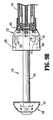
次に図1を参照すると、組織をステープル留めし、バットレス材料または、外科手術バットレスを組織に適用することにおいて使用するための例示的な外科手術ステープル留め装置または外科手術ステープラー10が開示される。このタイプの外科手術ステープル留め機器の例は、米国特許第7,128,253号に開示され、その開示全体は、本明細書中で参考として援用される。 Referring now to FIG. 1, an exemplary surgical stapling apparatus or surgical stapler 10 for use in stapling tissue and applying a buttress material or surgical buttress to tissue is disclosed. An example of this type of surgical stapling instrument is disclosed in US Pat. No. 7,128,253, the entire disclosure of which is hereby incorporated by reference.
外科手術ステープル留め装置10は、一般に、ハンドル12から遠位方向に延びる細長い管状部材14を有するハンドル12を含む。エンドエフェクタアセンブリ16は、細長い管状部材14の遠位端18に取り付けられる。エンドエフェクタアセンブリ16は、その中にステープルカートリッジ32を受け取るように構成された第1の顎またはステープルカートリッジアセンブリ200と、第2の顎またはアンビルアセンブリ300とを含む。エンドエフェクタアセンブリ16は、細長い管状部材14に永久的に付着され得るか、または着脱可能であることによって、新しいエンドエフェクタアセンブリ16と置換可能であり得る。ステープルカートリッジは、取り外し可能および置換可能であり得ることも企図される。ステープルカートリッジアセンブリ200およびアンビルアセンブリ300のうちの1つは、エンドエフェクタアセンブリ16の遠位端18に移動可能に取り付けられ、互いに離して間隔を空けられた開口した位置と互いに実質的に隣接した閉鎖した位置との間を移動可能である。アンビルアセンブリ300は、アンビルプレート302を支持し、金属材料(ステンレス鋼、チタン、チタン合金などが挙げられ、これらに限定されない)から製作される。ステープルカートリッジ32の少なくとも組織接触表面は、金属以外の材料(プラスチック、熱可塑性物質、樹脂、ポリカーボネートなどが挙げられ、これらに限定されない)から製作される。 Surgical stapling apparatus 10 generally includes a handle 12 having an elongated tubular member 14 extending distally from handle 12. End effector assembly 16 is attached to distal end 18 of elongate tubular member 14. End effector assembly 16 includes a first jaw or
外科手術ステープル留め装置10は、図1に示されるように、ハンドル12に移動可能に取り付けられたトリガー33をさらに含む。トリガー33の起動は、第1の顎および第2の顎を、開口した位置と閉鎖した位置との間で移動させるように初めは作動し、同時に、外科手術ステープル留め装置10を起動してステープルの線を組織に適用する。ステープル留めされるべき組織に対してエンドエフェクタアセンブリ16を適切に配向させるために、外科手術ステープル留め装置10は、ハンドル12に取り付けられた回転ノブ34をさらに備える。ハンドル12に対する回転ノブ34の回転は、ステープル留めされるべき組織に対してエンドエフェクタアセンブリ16を適切に配向させるために、ハンドル12に対して細長い管状部材14およびエンドエフェクタアセンブリ16を回転させる。 Surgical stapling apparatus 10 further includes a trigger 33 movably attached to handle 12, as shown in FIG. Activation of the trigger 33 initially operates to move the first and second jaws between the open and closed positions, while simultaneously activating the surgical stapling apparatus 10 to staple Apply the line to the tissue. In order to properly orient the end effector assembly 16 with respect to the tissue to be stapled, the surgical stapling apparatus 10 further comprises a
図6および図7に見られるように、ドライバー36は、第1の顎またはステープルカートリッジアセンブリ200および第2の顎またはアンビルアセンブリ300を開口した位置から閉鎖した位置まで寄せて移動させるために提供される。ドライバー36は、アンビルアセンブリ300のアンビルプレート302の中に形成された長手方向スロット338(図3)を通って移動する。ナイフ刃31を有するナイフ30は、ドライバー36に付随して、ドライバー36がスロット338通過するときに、ステープルカートリッジアセンブリ200とアンビルアセンブリ300との間に捕捉された組織を切断する。 As seen in FIGS. 6 and 7, a driver 36 is provided to move the first jaw or
例示的な外科手術ステープル留め装置10の構築および作動の詳細な議論について、上で参照された共有に係る米国特許第5,915,616号、同第6,330,965号、および同第6,241,139号が参照され得る。 For a detailed discussion of the construction and operation of the exemplary surgical stapling apparatus 10, see US Pat. Nos. 5,915,616, 6,330,965, and 6, referred to above for sharing. 241,139.
ステープルカートリッジアセンブリ200および/またはアンビルアセンブリ300は、外科手術バットレス500を備え得る。外科手術バットレス500は、外科手術ステープル留め装置10によって組織に適用されるステープルの線を強化するため、および密封するために提供される。外科手術バットレス500は、任意の外科手術ステープル留め、締付け、または発射の装置に適合させるために適した任意の形状、サイズ、または寸法に構成され得る。
より詳細に以下に記載される様式で、ステープルカートリッジアセンブリ200は、カートリッジバットレス500aを備え、アンビルアセンブリ300は、アンビルバットレス500bを備える。バットレス500a、500bは、任意の生体適合性の天然または合成の材料から作製され得る。バットレス500a、500bが形成される材料は、生体吸収性または非生体吸収性であり得る。天然材料、合成材料、生体吸収性材料、および非生体吸収性材料の任意の組み合わせが、バットレス材料を形成するために使用され得ることが理解されるべきである。バットレス500a、500bは、多孔層または非多孔層、多孔層および非多孔層の組み合わせであり得る。非多孔バットレス500a、500bは、周囲の組織からの組織の内方成長を遅らせるか、または防止し、それにより、接着バリアとして働き、望まれない瘢痕組織の形成を防止するように利用され得る。 In a manner described in more detail below, the
本明細書中に開示される外科手術ステープル留めデバイスと一緒に使用するための外科手術バットレス500a、500bのためのさらなる例示的な材料は、同一人に譲渡された米国特許第5,542,594号;同第5,908,427号;同第5,964,774号;および同第6,045,560号、ならびに2006年4月20日に出願された、同一人に譲渡された米国出願公開第2006/0085034号、および2006年6月22日に出願された、同第2006/0135992号に明記され、それらの各々の内容全体は、本明細書中で参考として援用される。 Additional exemplary materials for
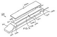
本実施形態に例示されるように、ならびに図2および図3に示されるように、外科手術バットレス500は、下に詳細に議論されるように、外科手術バットレス500a、500bをステープルカートリッジ32および/またはアンビルプレート302の内側に向いた表面または組織接触表面220、320に付着させる有利に位置決めされた取り付けパッド240、340によって、ステープルカートリッジアセンブリ200および/またはアンビルアセンブリ300に解放可能に取り付けられる。取り付けパッド240、340は、外科手術バットレス500a、500bと同じ分解性ポリマーから作製される。取り付けパッド240、340および外科手術バットレス500a、500bを同じ材料から構成することは、取り付けパッド240、340および外科手術バットレス500a、500bが、同じ融解温度および化学特性を有するので、より容易な結合を可能にする。 As illustrated in this embodiment, and as shown in FIGS. 2 and 3, surgical buttress 500 replaces surgical buttress 500a, 500b with
図2を参照すると、ステープルカートリッジアセンブリ200のカートリッジバットレス500aは、組織接触表面220の近位端260と遠位端262との両方の上に位置決めされた少なくとも1つの取り付けパッド240によって、ステープルカートリッジ32の組織接触表面220に作動可能に固定されるか、または、接着される。取り付けパッド240は、カートリッジバットレス500aと組織接触表面220との間に配置される。ステープルカートリッジアセンブリ200は、第1の外側エッジ248aと第2の外側エッジ248bとをさらに含む。図2に示されるように、遠位取り付けパッド240aは、第1の外側エッジ248aと、ステープルカートリッジアセンブリ200の中央長手方向スロット238の遠位端との間に配置される。同様に、遠位取り付けパッド240aは、第2の外側エッジ248bと中央長手方向スロット238の遠位端との間に配置される。近位取り付けゾーン240bは、第1の外側エッジ248aと中央長手方向スロット238の近位端との間、および第2の外側エッジ248bと中央長手方向スロット238の近位端との間に配置される。この実施形態において、中央取り付けパッド240cは、組織接触表面220の近位端260と遠位端262との間で、第1の外側エッジ248aと央長手方向スロット238との間、および第2の外側エッジ248bと中央長手方向スロット238との間に配置される。複数の取り付けパッド240が組織接触表面220に沿って、様々な位置に配置される他の実施形態が企図される。 Referring to FIG. 2, the cartridge buttress 500a of the
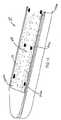
図3を参照すると、カートリッジバットレス500aと同様に、アンビルバットレス500bは、組織接触表面320の近位端360および遠位端362の両方の上に位置決めされた少なくとも1つの取り付けパッド340によって、アンビルアセンブリ300のアンビルプレート302の組織接触表面320に作動可能に固定または接着される。遠位取り付けパッド340aは、外側エッジ348a、348bと、中央長手方向スロット338の遠位端との間に配置される。近位取り付けパッド340bは、外側エッジ348a、348bと中央長手方向スロット338の近位端との間に配置される。さらに、中央取り付けゾーン340cは、近位端360と遠位端362との間で、外側エッジ348a、348bと中央長手方向スロット338との間に位置決めされる。 Referring to FIG. 3, like the cartridge buttress 500a, the anvil buttress 500b includes an anvil assembly with at least one
取り付けパッドは、円形、長円形、長方形であり得るか、または任意の形状を有し得、本明細書中に開示される実施形態のうちの任意のものにおいて、エンドエフェクタアセンブリの組織接触表面のうちの少なくとも1つの上に提供され得る。 The attachment pad can be circular, oval, rectangular, or have any shape, and in any of the embodiments disclosed herein, on the tissue contacting surface of the end effector assembly. It can be provided on at least one of them.
実施形態において、取り付けパッド240、340が、オーバー成形、射出成形によって、またはそれぞれの組織接触表面220、320に予備成形された部品をスナップばめし、固定することによって、ステープル保持ポケット52およびステープル形成ポケット68の中に配置されることが企図される。図4および図5は、ステープルカートリッジ32およびアンビルプレート302に配置されたバットレス500a、500bをそれぞれ例示する。図4に示されるように、取り付けパッド240は、ステープルカートリッジ200の組織接触表面220に沿って、選択的に位置決めされたステープル保持ポケット52内に配置され得る。同様に、図5に示されるように、取り付けパッド340は、アンビルプレート302の組織接触表面320に沿って、ステープル形成ポケット68内に配置される。 In embodiments, the
組み立て中、バットレス500a、500bは、ステープルカートリッジアセンブリ200およびアンビルアセンブリ300の組織接触表面220、320の各々の上にそれぞれ置かれる。超音波溶接は、バットレス500a、500bをそれぞれの取り付けパッド240、340に結合し、従って、それぞれの組織接触表面220、320に結合するために使用される。他の結合方法(例えば、レーザー溶接、溶剤結合、または熱圧)も想定される。上に記載されるように、バットレス500a、500bは、取り付けパッド240、340と同じ材料から作製されるので、バットレスと取り付けパッド240、340との間の結合力および解放力は、組織操作中およびステープラー位置決め中にバットレス材料が組織接触表面220、320に固定されたままであるように釣り合っている。本明細書中に開示される実施形態のうちの任意のものにおいて、取り付けゾーンまたはパッドが、アンビルプレートの長手方向スロット、ステープルカートリッジ32の長手方向スロット、または両方に配置され得ることも企図される。 During assembly, buttresses 500a, 500b are placed on each of
図6に例示されるように、外科手術ステープル留め装置10の使用中、その上に充填された外科手術バットレス500a、500b(上に記載されるように)を有する、第1の顎またはステープルカートリッジアセンブリ200、および第2の顎またはアンビルアセンブリ300は、外科手術部位のいずれかの側面に位置決めされる。ステープルカートリッジアセンブリ200およびアンビルアセンブリ300の組織接触表面220、320は、互いに締付けられるべき組織「T」の層に隣接して位置決めされる。 As illustrated in FIG. 6, during use of the surgical stapling apparatus 10, a first jaw or staple cartridge having
図7に示されるように、ステープルカートリッジアセンブリ200は、ステープルカートリッジ32の個々のステープル保持スロット52内に位置決めされた外科手術ステープル50を含む。ステープル50は、従来のタイプのものであり、バックスパン54から延びる1対のレッグ56および58を有するバックスパン54を含む。レッグ56および58は、組織貫通先端60および62においてそれぞれ終端する。プッシャー64は、ステープル保持スロット52内に位置し、ステープル50とウェッジ形状のそり66の経路との間に位置決めされる。 As shown in FIG. 7, the
例示された実施形態において、外科手術ステープル留め装置10は、ハンドル12(図1)に対するトリガー33の移動によって最初に起動され、ドライバー36を矢印「A」(図6)の方向に、アンビルプレート302の傾斜したエッジ21に対して移動させ、それによりアンビルアセンブリ300をステープルカートリッジアセンブリ200に対して閉鎖した位置に移動させる。駆動バー36がステープルカートリッジ32内を遠位方向に前進すると、駆動バー36は、ウェッジ形状のそり66と相互作用して、ステープル50のバックスパン54に対して上方方向にプッシャー64を促し、ステープル50のレッグ56および58を、カートリッジバットレス500a、組織「T」、およびアンビルバットレス500bを通して、アンビルアセンブリ300のアンビルプレート302中のステープル形成ポケットまたは凹部68に向かって駆動する。ステープルレッグ56および58の組織貫通先端60および62は、バックスパン54が組織「T」に対して外科手術バットレス500を固定した状態で、アンビルプレート302中のステープル形成ポケット68内で曲げられる。 In the illustrated embodiment, the surgical stapling apparatus 10 is first activated by movement of the trigger 33 relative to the handle 12 (FIG. 1), causing the driver 36 to move in the direction of arrow “A” (FIG. 6) and the
図7における実施形態に示されるように、取り付けゾーン240、340は、ステープルカートリッジ32およびアンビルプレート302のそれぞれの組織接触表面220、320とカートリッジバットレス500aおよびアンビルバットレス500bとの間にそれぞれ置かれる。発射後にエンドエフェクタアセンブリ16を開口することは、カートリッジバットレス500aと取り付けゾーン240との間の結合を解放し、それにより、カートリッジバットレス500aをステープルカートリッジ32の組織接触表面220から解放する。同様に、アンビルバットレス500bと取り付けゾーン340との間の結合は壊され、アンビルバットレス500bは、アンビルプレート302の組織接触表面320から解放される。上に記載されるように、バットレス500a、500bは、同じ材料から作製されるので、外科手術バットレス500a、500bとステープルカートリッジ32およびアンビルプレート302との間の結合の解放の際に、任意の非分解性材料をステープルカートリッジ32またはアンビルプレート302のいずれかから身体の中に移動させる、より少ないリスクが存在する。本明細書中で開示される実施形態のうちの任意のものにおいて、バットレスが取り付けゾーンまたはパッドと異なる材料から作製され得、生分解性、生体吸収性、生体再吸収性、または非生体吸収性であり得ることも企図される。生分解性材料、生体吸収性材料、生体再吸収性材料、または移植可能材料で作製される取り付けパッドまたはゾーンが好ましい。本明細書中に開示される実施形態のうちの任意のものにおいて、バットレス、取り付けパッドもしくはゾーン、または両方は、水、血液などへの曝露に応答して、身体の中ですばやく分解し、バットレスが機器から分離されることを可能にする材料から作製され得る。デンプン、糖、または塩が使用され得る。 As shown in the embodiment in FIG. 7, the
本明細書中に開示される実施形態のうちの任意のものにおいて、バットレスおよび取り付けパッドまたはゾーンは、同じかまたは同様の材料へのバットレスの容易な溶接を可能にするために、同じかまたは同様の材料から作製されることが企図される。パッドまたはゾーンに同じかまたは同様の材料を用いることには、バットレス着脱中にパッドまたはカートリッジから外れ得る外来非分解性材料が身体に入る懸念を避ける意図がある。 In any of the embodiments disclosed herein, the buttress and mounting pads or zones are the same or similar to allow easy welding of the buttress to the same or similar material. It is contemplated to be made from the following materials: The use of the same or similar material for the pad or zone is intended to avoid concerns that foreign non-degradable materials may enter the body that may come off the pad or cartridge during buttress removal.
外科手術ステープル留め装置10の完全な起動の際に、外科手術ステープル留め装置10に付随し、ドライバー36によって運ばれるナイフ30(図7)は、そのとき形成されたステープル50の列の間の組織「T」ならびに外科手術バットレス500a、500bを切断するために利用され得る。アンビルアセンブリ300の、ステープルカートリッジアセンブリ200から離して間隔が空けられた開口した位置への移動の際に、バットレス500a、500bは、それぞれのステープルカートリッジアセンブリ200およびアンビルアセンブリ300のそれぞれの組織接触表面220、320から引っ張られて離される。 Upon full activation of the surgical stapling apparatus 10, the knife 30 (FIG. 7) associated with the surgical stapling apparatus 10 and carried by the driver 36 is the tissue between the rows of
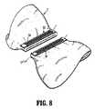
ステープル50でステープル留めして閉鎖され、分割された、結果として生じる組織「T」が、図8に例示される。特に、外科手術バットレス500a、500bは、ステープル50のレッグ56、58およびバックスパン54によって組織「T」に対して固定される。従って、外科手術バットレス500a、500bは、組織「T」に対してステープル留めされ、それにより、ステープル50によって作り出されるステープルの線を密閉し、強化する。 The resulting tissue “T” stapled closed with
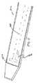
次に図9Aおよび図9Bを参照すると、本開示の外科手術バットレス124と一緒に使用するための輪状の外科手術ステープル留め装置110が示される。外科手術ステープル留め装置110は、少なくとも1つの旋回可能な起動ハンドル部材133、および前進部材135を有するハンドルアセンブリ112を含む。ハンドル部材112から延びている、その長さに沿って湾曲した形状を有するように構築され得る管状本体部分114が提供される。本体部分114は、ステープル保持スロット152の各々に配置されたステープル150を有するステープル保持スロット152の1対の輪状の並びを含むステープルカートリッジアセンブリ122において終端する。ステープルカートリッジ122の遠位に位置決めされた、アンビル部材121と、アンビルアセンブリ120をステープル留め装置110の遠位端部分に取り外し可能に接続するための、アンビル部材121に作動可能に付随するシャフト123とを含むアンビルアセンブリ120が提供される。 Referring now to FIGS. 9A and 9B, an annular
ステープルカートリッジアセンブリ122は、管状本体部分114の遠位端に固定して接続され得るか、または管状本体部分114の遠位端内に同心に嵌まるように構成され得る。ステープルカートリッジアセンブリ122は、ほぼ円錐台の形状を有する近位部分と、周方向に間隔が空けられたフィンガー(示されない)の2つの同心リングを規定する遠位部分とを含むステープルプッシャー164を含み、そのフィンガーの各々は、それぞれのステープル保持スロット152内に受け取られる。
ナイフ130は、実質的に開いた杯の形態であり、そのリムがナイフ刃131を規定し、ステープルカートリッジアセンブリ122内に配置され、ステープルプッシャー164の遠位表面に取り付けられる。ナイフ130は、ステープル150の1対の輪状の並びの、半径方向に内方に配置される。従って、使用において、ステープルプッシャー164が前進すると、ナイフ130も軸方向に遠位方向に前進する。 The
図10Aに見られるように、外科手術バットレス124は、外科手術バットレス124とステープルカートリッジアセンブリ122の組織接触表面134との間に配置された取り付けパッド140において、ステープルカートリッジアセンブリ122に解放可能に取り付けられる。本明細書中で上に記載されるように、取り付けパッド140は、外科手術バットレス124を組織接触表面134に結合させる。外科手術バットレス124は、輪状の構成で提供され、それを通してアンビルアセンブリ120のシャフト123を受け取るために中央アパーチャ125を含む。 As seen in FIG. 10A, the surgical buttress 124 is releasably attached to the
外科手術バットレス124は、さらに、または代替的に、ステープルカートリッジアセンブリ122に取り付けられる外科手術バットレス124と同様の様式で、アンビルプレート121の組織接触表面に取り付けられ得るか、または接着され得ることが想定される。 It is envisioned that surgical buttress 124 may additionally or alternatively be attached to or adhered to the tissue contacting surface of
図10Bに示されるように、外科手術バットレス124は、外科手術バットレス124の内側部分または周縁エッジ160、および外側部分または周縁エッジ162に沿って、ステープルカートリッジ122に固定され得るか、または接着され得る。外科手術バットレス124をステープルカートリッジアセンブリ122に保持するために他の構成(例えば、ステープルカートリッジ32に関して議論されたように取り付けパッド140をステープル保持スロット内に配置すること、またはステープル保持スロット152間で取り付けゾーン140を交換すること、または当業者の知識の範囲内である他の構成の中で)が利用され得ることが想定される。 As shown in FIG. 10B, surgical buttress 124 may be secured to or adhered to
外科手術ステープル留め装置110および着脱可能なアンビルアセンブリ120は、腸のセクション50と52とを接合することを達成するための吻合手順において使用される。吻合手順は、代表的に、最小限に侵襲性の外科手術技術(腹腔鏡の手段および機器が挙げられる)を用いて実施される。図11に示される手順の時点において、病的な腸のセクションは予め取り除かれており、アンビルアセンブリ120(必要に応じて、その上に外科手術バットレス124を含む)は、外科手術切開を介してか、または経肛門のいずれかで手術部位に適用され、腸のセクション52内に位置決めされ、外科手術ステープル留め装置110(必要に応じて、その上に外科手術バットレス124を含む)の管状本体部分114が、腸のセクション50に経肛門挿入されている。図12に例示されるように、従来の手段(例えば、巾着縫合「P」)によって、それらのそれぞれの構成要素(例えば、アンビルアセンブリ120のシャフト123、および管状本体部分114の遠位端)の周りに一時的に固定された腸のセクション50および52も示される。
その後、臨床医は、シャフト123の近位端が外科手術ステープル留め装置110の管状本体部分114の遠位端に挿入されるまでアンビルアセンブリ120を操り、管状本体部分114の遠位端内の取り付け構造(示されない)が、取り付けを達成するためにシャフト123を係合する。アンビルアセンブリ120および管状本体部分114は次に、腸のセクション50、52を寄せるために寄せられる。外科手術ステープル留め装置110は次に発射される。ナイフ(示されない)は、ナイフの半径方向に内方に配置された組織および外科手術バットレス124の部分を切断して、吻合を完了する。外科手術バットレス124が腸のセクション50および52にステープル留めされた状態で、アンビルアセンブリ120およびステープルカートリッジアセンブリ122の開口する力は、取り付けパッド140において外科手術バットレス124を解放させ、それにより、組織接触表面134から外科手術バットレス124を解放する。 Thereafter, the clinician manipulates the
本明細書中に具体的に記載され、添付の図面に例示されるデバイスおよび方法が、非限定的な例示的な実施形態であること、ならびに記載、開示、および図面が、特定の実施形態の単なる例示であると解釈されるべきであることを当業者は理解する。例えば、外科手術機器が、本明細書中に開示された実施形態のうちの任意のものにおいて、手動で、またはモータの動力を備え得ることが企図される。従って、本開示は、記載される正確な実施形態に限定されないこと、ならびに種々の他の変化および改変が、本開示の範囲または趣旨から外れることなく、当業者によって達成され得ることが理解されるべきである。さらに、1つの例示的な実施形態に関して例示されるか、または記載される要素および特徴が、本開示の範囲から外れることなく、別の例示的な実施形態の要素および特徴に組み合わせられ得ること、ならびにそのような改変およびバリエーションがまた、本開示の範囲に含まれることが意図されることが想定される。従って、本開示の主題は、添付の特許請求の範囲によって示される場合を除いて、特に示され、記載されたことによって限定されるべきではない。 The devices and methods specifically described herein and illustrated in the accompanying drawings are non-limiting exemplary embodiments, and the description, disclosure, and drawings are illustrative of particular embodiments. Those skilled in the art will appreciate that it should be construed as merely illustrative. For example, it is contemplated that the surgical instrument may be powered manually or with motor power in any of the embodiments disclosed herein. Accordingly, it is understood that this disclosure is not limited to the precise embodiments described, and that various other changes and modifications can be accomplished by those skilled in the art without departing from the scope or spirit of this disclosure. Should. Further, the elements and features illustrated or described with respect to one exemplary embodiment may be combined with the elements and features of another exemplary embodiment without departing from the scope of the disclosure. And such modifications and variations are also intended to be included within the scope of the present disclosure. Accordingly, the subject matter of the present disclosure should not be limited by what has been particularly shown and described, except as indicated by the appended claims.
10 外科手術ステープラー
16 エンドエフェクタアセンブリ
120、300 アンビルアセンブリ
124、500a、500b バットレス
134、220、320 組織接触表面
140、240、340 取り付けパッド10 Surgical Stapler 16
Claims (19)
Translated fromJapanese組織接触表面を有するステープルカートリッジアセンブリと、
組織接触表面を有するアンビルアセンブリと、
該ステープルカートリッジアセンブリおよびアンビルアセンブリのうちの少なくとも1つの該組織接触表面の少なくとも一部分に実質的に重なるような構成および寸法にされた外科手術バットレスと、
複数の取り付けパッドであって、該複数の取り付けパッドは、少なくとも1つの該ステープルカートリッジアセンブリおよびアンビルアセンブリの該組織接触表面のうちの少なくとも1つに固定され、それぞれのバットレス材料を該組織接触表面に保持するように構成された、複数の取り付けパッドと
を含み、
該外科手術バットレスは、該複数の取り付けパッドの各々に超音波溶接されている、
エンドエフェクタアセンブリ。An end effector assembly for use with a surgical stapler, the end effector assembly comprising:
A staple cartridge assembly having a tissue contacting surface;
An anvil assembly having a tissue contacting surface;
A surgical buttress configured and dimensioned to substantially overlap at least a portion of the tissue contacting surface of at least one of the staple cartridge assembly and anvil assembly;
A plurality of attachment pads, wherein the plurality of attachment pads are secured to at least one of the tissue contacting surfaces of at least one staple cartridge assembly and an anvil assembly, and each buttress material is attached to the tissue contacting surface. A plurality of mounting pads configured to hold and
The surgical buttress is ultrasonically welded to each of the plurality of mounting pads;
End effector assembly.
複数のステープル保持スロットを規定する組織接触表面を含むカートリッジ本体と、
該カートリッジ本体の各ステープル保持スロット内に配置されたステープルと、
該カートリッジ本体の該ステープル保持スロットの少なくとも一部分に実質的に重なるような構成および寸法にされた外科手術バットレスと、
複数の取り付けパッドであって、該複数の取り付けパッドは、該カートリッジ本体の該組織接触表面に固定され、それぞれのバットレス材料を該組織接触表面に保持するように構成された、複数の取り付けパッドと
を含み、
該外科手術バットレスは、該複数の取り付けパッドの各々に超音波溶接されている、
ステープルカートリッジ。A staple cartridge for use with a surgical stapling apparatus, the staple cartridge comprising:
A cartridge body including a tissue contacting surface defining a plurality of staple retaining slots;
Staples disposed in each staple holding slot of the cartridge body;
A surgical buttress configured and dimensioned to substantially overlap at least a portion of the staple retaining slot of the cartridge body;
A plurality of attachment pads, wherein the plurality of attachment pads are secured to the tissue contacting surface of the cartridge body and configured to hold a respective buttress material on the tissue contacting surface; Including
The surgical buttress is ultrasonically welded to each of the plurality of mounting pads;
Staple cartridge.
ハウジングと、
該ハウジングに固定されたエンドエフェクタと、組織接触表面を有するステープルカートリッジアセンブリと、組織接触表面を有するアンビルアセンブリと、
該ステープルカートリッジアセンブリおよびアンビルアセンブリのうちの少なくとも1つの該組織接触表面の少なくとも一部分に実質的に重なるような構成および寸法にされた外科手術バットレスと、
複数の取り付けパッドであって、該複数の取り付けパッドは、少なくとも1つの該ステープルカートリッジアセンブリおよびアンビルアセンブリの該組織接触表面のうちの少なくとも1つに固定され、それぞれのバットレス材料を該組織接触表面に保持するように構成された、複数の取り付けパッドと
を含み、
該外科手術バットレスは、該複数の取り付けパッドの各々に超音波溶接されている、
外科手術ステープル留め装置。Surgical stapling apparatus, the surgical stapling apparatus comprising:
A housing;
An end effector secured to the housing; a staple cartridge assembly having a tissue contacting surface; and an anvil assembly having a tissue contacting surface;
A surgical buttress configured and dimensioned to substantially overlap at least a portion of the tissue contacting surface of at least one of the staple cartridge assembly and anvil assembly;
A plurality of attachment pads, wherein the plurality of attachment pads are secured to at least one of the tissue contacting surfaces of at least one staple cartridge assembly and an anvil assembly, and each buttress material is attached to the tissue contacting surface. A plurality of mounting pads configured to hold and
The surgical buttress is ultrasonically welded to each of the plurality of mounting pads;
Surgical stapling device.
Applications Claiming Priority (2)
| Application Number | Priority Date | Filing Date | Title |
|---|---|---|---|
| US13/586,261US9351732B2 (en) | 2011-12-14 | 2012-08-15 | Buttress attachment to degradable polymer zones |
| US13/586,261 | 2012-08-15 |
Related Child Applications (1)
| Application Number | Title | Priority Date | Filing Date |
|---|---|---|---|
| JP2018077523ADivisionJP2018110929A (en) | 2012-08-15 | 2018-04-13 | Buttress attachment to degradable polymer zones |
Publications (2)
| Publication Number | Publication Date |
|---|---|
| JP2014036842Atrue JP2014036842A (en) | 2014-02-27 |
| JP6362307B2 JP6362307B2 (en) | 2018-07-25 |
Family
ID=48951407
Family Applications (3)
| Application Number | Title | Priority Date | Filing Date |
|---|---|---|---|
| JP2013154561AExpired - Fee RelatedJP6362307B2 (en) | 2012-08-15 | 2013-07-25 | Attaching the buttress to the degradable polymer zone |
| JP2018077523AWithdrawnJP2018110929A (en) | 2012-08-15 | 2018-04-13 | Buttress attachment to degradable polymer zones |
| JP2019176738APendingJP2020014881A (en) | 2012-08-15 | 2019-09-27 | Buttress attachment to degradable polymer zones |
Family Applications After (2)
| Application Number | Title | Priority Date | Filing Date |
|---|---|---|---|
| JP2018077523AWithdrawnJP2018110929A (en) | 2012-08-15 | 2018-04-13 | Buttress attachment to degradable polymer zones |
| JP2019176738APendingJP2020014881A (en) | 2012-08-15 | 2019-09-27 | Buttress attachment to degradable polymer zones |
Country Status (6)
| Country | Link |
|---|---|
| EP (1) | EP2698118B1 (en) |
| JP (3) | JP6362307B2 (en) |
| CN (1) | CN103584893B (en) |
| AU (1) | AU2013206804B2 (en) |
| CA (1) | CA2821619C (en) |
| ES (1) | ES2645420T3 (en) |
Cited By (3)
| Publication number | Priority date | Publication date | Assignee | Title |
|---|---|---|---|---|
| JP2018512218A (en)* | 2015-03-25 | 2018-05-17 | エシコン エルエルシーEthicon LLC | How to apply a support to a surgical stapler |
| JP2018531682A (en)* | 2015-09-30 | 2018-11-01 | エシコン エルエルシーEthicon LLC | Compressible appendage with mounting area |
| JP2020508126A (en)* | 2017-02-17 | 2020-03-19 | エシコン エルエルシーEthicon LLC | Method and apparatus for delivering and securing an auxiliary material to a treatment site |
Families Citing this family (363)
| Publication number | Priority date | Publication date | Assignee | Title |
|---|---|---|---|---|
| US9060770B2 (en) | 2003-05-20 | 2015-06-23 | Ethicon Endo-Surgery, Inc. | Robotically-driven surgical instrument with E-beam driver |
| US20070084897A1 (en) | 2003-05-20 | 2007-04-19 | Shelton Frederick E Iv | Articulating surgical stapling instrument incorporating a two-piece e-beam firing mechanism |
| US11998198B2 (en) | 2004-07-28 | 2024-06-04 | Cilag Gmbh International | Surgical stapling instrument incorporating a two-piece E-beam firing mechanism |
| US8215531B2 (en) | 2004-07-28 | 2012-07-10 | Ethicon Endo-Surgery, Inc. | Surgical stapling instrument having a medical substance dispenser |
| US11890012B2 (en) | 2004-07-28 | 2024-02-06 | Cilag Gmbh International | Staple cartridge comprising cartridge body and attached support |
| US9072535B2 (en) | 2011-05-27 | 2015-07-07 | Ethicon Endo-Surgery, Inc. | Surgical stapling instruments with rotatable staple deployment arrangements |
| US11246590B2 (en) | 2005-08-31 | 2022-02-15 | Cilag Gmbh International | Staple cartridge including staple drivers having different unfired heights |
| US7934630B2 (en) | 2005-08-31 | 2011-05-03 | Ethicon Endo-Surgery, Inc. | Staple cartridges for forming staples having differing formed staple heights |
| US11484312B2 (en) | 2005-08-31 | 2022-11-01 | Cilag Gmbh International | Staple cartridge comprising a staple driver arrangement |
| US9237891B2 (en) | 2005-08-31 | 2016-01-19 | Ethicon Endo-Surgery, Inc. | Robotically-controlled surgical stapling devices that produce formed staples having different lengths |
| US10159482B2 (en) | 2005-08-31 | 2018-12-25 | Ethicon Llc | Fastener cartridge assembly comprising a fixed anvil and different staple heights |
| US7669746B2 (en) | 2005-08-31 | 2010-03-02 | Ethicon Endo-Surgery, Inc. | Staple cartridges for forming staples having differing formed staple heights |
| US20070106317A1 (en) | 2005-11-09 | 2007-05-10 | Shelton Frederick E Iv | Hydraulically and electrically actuated articulation joints for surgical instruments |
| US11793518B2 (en) | 2006-01-31 | 2023-10-24 | Cilag Gmbh International | Powered surgical instruments with firing system lockout arrangements |
| US20110295295A1 (en) | 2006-01-31 | 2011-12-01 | Ethicon Endo-Surgery, Inc. | Robotically-controlled surgical instrument having recording capabilities |
| US8186555B2 (en) | 2006-01-31 | 2012-05-29 | Ethicon Endo-Surgery, Inc. | Motor-driven surgical cutting and fastening instrument with mechanical closure system |
| US8708213B2 (en) | 2006-01-31 | 2014-04-29 | Ethicon Endo-Surgery, Inc. | Surgical instrument having a feedback system |
| US11278279B2 (en) | 2006-01-31 | 2022-03-22 | Cilag Gmbh International | Surgical instrument assembly |
| US20110024477A1 (en) | 2009-02-06 | 2011-02-03 | Hall Steven G | Driven Surgical Stapler Improvements |
| US7753904B2 (en) | 2006-01-31 | 2010-07-13 | Ethicon Endo-Surgery, Inc. | Endoscopic surgical instrument with a handle that can articulate with respect to the shaft |
| US20120292367A1 (en) | 2006-01-31 | 2012-11-22 | Ethicon Endo-Surgery, Inc. | Robotically-controlled end effector |
| US8820603B2 (en) | 2006-01-31 | 2014-09-02 | Ethicon Endo-Surgery, Inc. | Accessing data stored in a memory of a surgical instrument |
| US11224427B2 (en) | 2006-01-31 | 2022-01-18 | Cilag Gmbh International | Surgical stapling system including a console and retraction assembly |
| US7845537B2 (en) | 2006-01-31 | 2010-12-07 | Ethicon Endo-Surgery, Inc. | Surgical instrument having recording capabilities |
| US8992422B2 (en) | 2006-03-23 | 2015-03-31 | Ethicon Endo-Surgery, Inc. | Robotically-controlled endoscopic accessory channel |
| US8322455B2 (en) | 2006-06-27 | 2012-12-04 | Ethicon Endo-Surgery, Inc. | Manually driven surgical cutting and fastening instrument |
| US10568652B2 (en) | 2006-09-29 | 2020-02-25 | Ethicon Llc | Surgical staples having attached drivers of different heights and stapling instruments for deploying the same |
| US11980366B2 (en) | 2006-10-03 | 2024-05-14 | Cilag Gmbh International | Surgical instrument |
| US8632535B2 (en) | 2007-01-10 | 2014-01-21 | Ethicon Endo-Surgery, Inc. | Interlock and surgical instrument including same |
| US11291441B2 (en) | 2007-01-10 | 2022-04-05 | Cilag Gmbh International | Surgical instrument with wireless communication between control unit and remote sensor |
| US8684253B2 (en) | 2007-01-10 | 2014-04-01 | Ethicon Endo-Surgery, Inc. | Surgical instrument with wireless communication between a control unit of a robotic system and remote sensor |
| US20080169333A1 (en) | 2007-01-11 | 2008-07-17 | Shelton Frederick E | Surgical stapler end effector with tapered distal end |
| US11039836B2 (en) | 2007-01-11 | 2021-06-22 | Cilag Gmbh International | Staple cartridge for use with a surgical stapling instrument |
| US7673782B2 (en) | 2007-03-15 | 2010-03-09 | Ethicon Endo-Surgery, Inc. | Surgical stapling instrument having a releasable buttress material |
| US11564682B2 (en) | 2007-06-04 | 2023-01-31 | Cilag Gmbh International | Surgical stapler device |
| US8931682B2 (en) | 2007-06-04 | 2015-01-13 | Ethicon Endo-Surgery, Inc. | Robotically-controlled shaft based rotary drive systems for surgical instruments |
| US7753245B2 (en) | 2007-06-22 | 2010-07-13 | Ethicon Endo-Surgery, Inc. | Surgical stapling instruments |
| US11849941B2 (en) | 2007-06-29 | 2023-12-26 | Cilag Gmbh International | Staple cartridge having staple cavities extending at a transverse angle relative to a longitudinal cartridge axis |
| US7866527B2 (en) | 2008-02-14 | 2011-01-11 | Ethicon Endo-Surgery, Inc. | Surgical stapling apparatus with interlockable firing system |
| US11986183B2 (en) | 2008-02-14 | 2024-05-21 | Cilag Gmbh International | Surgical cutting and fastening instrument comprising a plurality of sensors to measure an electrical parameter |
| US8573465B2 (en) | 2008-02-14 | 2013-11-05 | Ethicon Endo-Surgery, Inc. | Robotically-controlled surgical end effector system with rotary actuated closure systems |
| US7819298B2 (en) | 2008-02-14 | 2010-10-26 | Ethicon Endo-Surgery, Inc. | Surgical stapling apparatus with control features operable with one hand |
| US9179912B2 (en) | 2008-02-14 | 2015-11-10 | Ethicon Endo-Surgery, Inc. | Robotically-controlled motorized surgical cutting and fastening instrument |
| US8636736B2 (en) | 2008-02-14 | 2014-01-28 | Ethicon Endo-Surgery, Inc. | Motorized surgical cutting and fastening instrument |
| JP5410110B2 (en) | 2008-02-14 | 2014-02-05 | エシコン・エンド−サージェリィ・インコーポレイテッド | Surgical cutting / fixing instrument with RF electrode |
| US9585657B2 (en) | 2008-02-15 | 2017-03-07 | Ethicon Endo-Surgery, Llc | Actuator for releasing a layer of material from a surgical end effector |
| US8210411B2 (en) | 2008-09-23 | 2012-07-03 | Ethicon Endo-Surgery, Inc. | Motor-driven surgical cutting instrument |
| US11648005B2 (en) | 2008-09-23 | 2023-05-16 | Cilag Gmbh International | Robotically-controlled motorized surgical instrument with an end effector |
| US9005230B2 (en) | 2008-09-23 | 2015-04-14 | Ethicon Endo-Surgery, Inc. | Motorized surgical instrument |
| US9386983B2 (en) | 2008-09-23 | 2016-07-12 | Ethicon Endo-Surgery, Llc | Robotically-controlled motorized surgical instrument |
| US8608045B2 (en) | 2008-10-10 | 2013-12-17 | Ethicon Endo-Sugery, Inc. | Powered surgical cutting and stapling apparatus with manually retractable firing system |
| US8517239B2 (en) | 2009-02-05 | 2013-08-27 | Ethicon Endo-Surgery, Inc. | Surgical stapling instrument comprising a magnetic element driver |
| RU2525225C2 (en) | 2009-02-06 | 2014-08-10 | Этикон Эндо-Серджери, Инк. | Improvement of drive surgical suturing instrument |
| US8851354B2 (en) | 2009-12-24 | 2014-10-07 | Ethicon Endo-Surgery, Inc. | Surgical cutting instrument that analyzes tissue thickness |
| US8220688B2 (en) | 2009-12-24 | 2012-07-17 | Ethicon Endo-Surgery, Inc. | Motor-driven surgical cutting instrument with electric actuator directional control assembly |
| US8783543B2 (en) | 2010-07-30 | 2014-07-22 | Ethicon Endo-Surgery, Inc. | Tissue acquisition arrangements and methods for surgical stapling devices |
| US11298125B2 (en) | 2010-09-30 | 2022-04-12 | Cilag Gmbh International | Tissue stapler having a thickness compensator |
| US9016542B2 (en) | 2010-09-30 | 2015-04-28 | Ethicon Endo-Surgery, Inc. | Staple cartridge comprising compressible distortion resistant components |
| US11812965B2 (en) | 2010-09-30 | 2023-11-14 | Cilag Gmbh International | Layer of material for a surgical end effector |
| US9386988B2 (en) | 2010-09-30 | 2016-07-12 | Ethicon End-Surgery, LLC | Retainer assembly including a tissue thickness compensator |
| US9351730B2 (en) | 2011-04-29 | 2016-05-31 | Ethicon Endo-Surgery, Llc | Tissue thickness compensator comprising channels |
| US9788834B2 (en) | 2010-09-30 | 2017-10-17 | Ethicon Llc | Layer comprising deployable attachment members |
| US12213666B2 (en) | 2010-09-30 | 2025-02-04 | Cilag Gmbh International | Tissue thickness compensator comprising layers |
| US10945731B2 (en) | 2010-09-30 | 2021-03-16 | Ethicon Llc | Tissue thickness compensator comprising controlled release and expansion |
| US9629814B2 (en) | 2010-09-30 | 2017-04-25 | Ethicon Endo-Surgery, Llc | Tissue thickness compensator configured to redistribute compressive forces |
| US11925354B2 (en) | 2010-09-30 | 2024-03-12 | Cilag Gmbh International | Staple cartridge comprising staples positioned within a compressible portion thereof |
| US8695866B2 (en) | 2010-10-01 | 2014-04-15 | Ethicon Endo-Surgery, Inc. | Surgical instrument having a power control circuit |
| AU2012250197B2 (en) | 2011-04-29 | 2017-08-10 | Ethicon Endo-Surgery, Inc. | Staple cartridge comprising staples positioned within a compressible portion thereof |
| US11207064B2 (en) | 2011-05-27 | 2021-12-28 | Cilag Gmbh International | Automated end effector component reloading system for use with a robotic system |
| BR112014024098B1 (en) | 2012-03-28 | 2021-05-25 | Ethicon Endo-Surgery, Inc. | staple cartridge |
| MX358135B (en) | 2012-03-28 | 2018-08-06 | Ethicon Endo Surgery Inc | Tissue thickness compensator comprising a plurality of layers. |
| JP6224070B2 (en) | 2012-03-28 | 2017-11-01 | エシコン・エンド−サージェリィ・インコーポレイテッドEthicon Endo−Surgery,Inc. | Retainer assembly including tissue thickness compensator |
| US9101358B2 (en) | 2012-06-15 | 2015-08-11 | Ethicon Endo-Surgery, Inc. | Articulatable surgical instrument comprising a firing drive |
| US9408606B2 (en) | 2012-06-28 | 2016-08-09 | Ethicon Endo-Surgery, Llc | Robotically powered surgical device with manually-actuatable reversing system |
| US9282974B2 (en) | 2012-06-28 | 2016-03-15 | Ethicon Endo-Surgery, Llc | Empty clip cartridge lockout |
| US12383267B2 (en) | 2012-06-28 | 2025-08-12 | Cilag Gmbh International | Robotically powered surgical device with manually-actuatable reversing system |
| JP6290201B2 (en) | 2012-06-28 | 2018-03-07 | エシコン・エンド−サージェリィ・インコーポレイテッドEthicon Endo−Surgery,Inc. | Lockout for empty clip cartridge |
| US20140001231A1 (en) | 2012-06-28 | 2014-01-02 | Ethicon Endo-Surgery, Inc. | Firing system lockout arrangements for surgical instruments |
| BR112014032776B1 (en) | 2012-06-28 | 2021-09-08 | Ethicon Endo-Surgery, Inc | SURGICAL INSTRUMENT SYSTEM AND SURGICAL KIT FOR USE WITH A SURGICAL INSTRUMENT SYSTEM |
| US9289256B2 (en) | 2012-06-28 | 2016-03-22 | Ethicon Endo-Surgery, Llc | Surgical end effectors having angled tissue-contacting surfaces |
| US11278284B2 (en) | 2012-06-28 | 2022-03-22 | Cilag Gmbh International | Rotary drive arrangements for surgical instruments |
| BR112015021082B1 (en) | 2013-03-01 | 2022-05-10 | Ethicon Endo-Surgery, Inc | surgical instrument |
| RU2672520C2 (en) | 2013-03-01 | 2018-11-15 | Этикон Эндо-Серджери, Инк. | Hingedly turnable surgical instruments with conducting ways for signal transfer |
| US9629629B2 (en) | 2013-03-14 | 2017-04-25 | Ethicon Endo-Surgey, LLC | Control systems for surgical instruments |
| US9808244B2 (en) | 2013-03-14 | 2017-11-07 | Ethicon Llc | Sensor arrangements for absolute positioning system for surgical instruments |
| BR112015026109B1 (en) | 2013-04-16 | 2022-02-22 | Ethicon Endo-Surgery, Inc | surgical instrument |
| US9826976B2 (en) | 2013-04-16 | 2017-11-28 | Ethicon Llc | Motor driven surgical instruments with lockable dual drive shafts |
| US9775609B2 (en) | 2013-08-23 | 2017-10-03 | Ethicon Llc | Tamper proof circuit for surgical instrument battery pack |
| MX369362B (en) | 2013-08-23 | 2019-11-06 | Ethicon Endo Surgery Llc | Firing member retraction devices for powered surgical instruments. |
| US9962161B2 (en) | 2014-02-12 | 2018-05-08 | Ethicon Llc | Deliverable surgical instrument |
| US10004497B2 (en) | 2014-03-26 | 2018-06-26 | Ethicon Llc | Interface systems for use with surgical instruments |
| US20150272580A1 (en) | 2014-03-26 | 2015-10-01 | Ethicon Endo-Surgery, Inc. | Verification of number of battery exchanges/procedure count |
| US12232723B2 (en) | 2014-03-26 | 2025-02-25 | Cilag Gmbh International | Systems and methods for controlling a segmented circuit |
| BR112016021943B1 (en) | 2014-03-26 | 2022-06-14 | Ethicon Endo-Surgery, Llc | SURGICAL INSTRUMENT FOR USE BY AN OPERATOR IN A SURGICAL PROCEDURE |
| US10013049B2 (en) | 2014-03-26 | 2018-07-03 | Ethicon Llc | Power management through sleep options of segmented circuit and wake up control |
| BR112016023825B1 (en) | 2014-04-16 | 2022-08-02 | Ethicon Endo-Surgery, Llc | STAPLE CARTRIDGE FOR USE WITH A SURGICAL STAPLER AND STAPLE CARTRIDGE FOR USE WITH A SURGICAL INSTRUMENT |
| US10327764B2 (en) | 2014-09-26 | 2019-06-25 | Ethicon Llc | Method for creating a flexible staple line |
| CN106456159B (en) | 2014-04-16 | 2019-03-08 | 伊西康内外科有限责任公司 | Fastener Cartridge Assembly and Nail Retainer Cover Arrangement |
| US10470768B2 (en) | 2014-04-16 | 2019-11-12 | Ethicon Llc | Fastener cartridge including a layer attached thereto |
| US20150297225A1 (en) | 2014-04-16 | 2015-10-22 | Ethicon Endo-Surgery, Inc. | Fastener cartridges including extensions having different configurations |
| CN106456176B (en) | 2014-04-16 | 2019-06-28 | 伊西康内外科有限责任公司 | Fastener Cartridge Including Extensions With Different Configurations |
| US10135242B2 (en) | 2014-09-05 | 2018-11-20 | Ethicon Llc | Smart cartridge wake up operation and data retention |
| US11311294B2 (en) | 2014-09-05 | 2022-04-26 | Cilag Gmbh International | Powered medical device including measurement of closure state of jaws |
| BR112017004361B1 (en) | 2014-09-05 | 2023-04-11 | Ethicon Llc | ELECTRONIC SYSTEM FOR A SURGICAL INSTRUMENT |
| US10105142B2 (en) | 2014-09-18 | 2018-10-23 | Ethicon Llc | Surgical stapler with plurality of cutting elements |
| CN107427300B (en)* | 2014-09-26 | 2020-12-04 | 伊西康有限责任公司 | Surgical suture buttresses and auxiliary materials |
| US11523821B2 (en) | 2014-09-26 | 2022-12-13 | Cilag Gmbh International | Method for creating a flexible staple line |
| US9924944B2 (en) | 2014-10-16 | 2018-03-27 | Ethicon Llc | Staple cartridge comprising an adjunct material |
| US11141153B2 (en) | 2014-10-29 | 2021-10-12 | Cilag Gmbh International | Staple cartridges comprising driver arrangements |
| US10517594B2 (en) | 2014-10-29 | 2019-12-31 | Ethicon Llc | Cartridge assemblies for surgical staplers |
| US9844376B2 (en) | 2014-11-06 | 2017-12-19 | Ethicon Llc | Staple cartridge comprising a releasable adjunct material |
| US10736636B2 (en) | 2014-12-10 | 2020-08-11 | Ethicon Llc | Articulatable surgical instrument system |
| MX389118B (en) | 2014-12-18 | 2025-03-20 | Ethicon Llc | SURGICAL INSTRUMENT WITH AN ANVIL THAT CAN BE SELECTIVELY MOVED ON A DISCRETE, NON-MOBILE AXIS RELATIVE TO A STAPLE CARTRIDGE. |
| US9987000B2 (en) | 2014-12-18 | 2018-06-05 | Ethicon Llc | Surgical instrument assembly comprising a flexible articulation system |
| US9844375B2 (en) | 2014-12-18 | 2017-12-19 | Ethicon Llc | Drive arrangements for articulatable surgical instruments |
| US10085748B2 (en) | 2014-12-18 | 2018-10-02 | Ethicon Llc | Locking arrangements for detachable shaft assemblies with articulatable surgical end effectors |
| US9943309B2 (en) | 2014-12-18 | 2018-04-17 | Ethicon Llc | Surgical instruments with articulatable end effectors and movable firing beam support arrangements |
| US9844374B2 (en) | 2014-12-18 | 2017-12-19 | Ethicon Llc | Surgical instrument systems comprising an articulatable end effector and means for adjusting the firing stroke of a firing member |
| US11154301B2 (en) | 2015-02-27 | 2021-10-26 | Cilag Gmbh International | Modular stapling assembly |
| US10245033B2 (en) | 2015-03-06 | 2019-04-02 | Ethicon Llc | Surgical instrument comprising a lockable battery housing |
| US9993248B2 (en) | 2015-03-06 | 2018-06-12 | Ethicon Endo-Surgery, Llc | Smart sensors with local signal processing |
| JP2020121162A (en) | 2015-03-06 | 2020-08-13 | エシコン エルエルシーEthicon LLC | Time dependent evaluation of sensor data to determine stability element, creep element and viscoelastic element of measurement |
| US10548504B2 (en) | 2015-03-06 | 2020-02-04 | Ethicon Llc | Overlaid multi sensor radio frequency (RF) electrode system to measure tissue compression |
| US10441279B2 (en) | 2015-03-06 | 2019-10-15 | Ethicon Llc | Multiple level thresholds to modify operation of powered surgical instruments |
| US10433844B2 (en) | 2015-03-31 | 2019-10-08 | Ethicon Llc | Surgical instrument with selectively disengageable threaded drive systems |
| US10835249B2 (en) | 2015-08-17 | 2020-11-17 | Ethicon Llc | Implantable layers for a surgical instrument |
| US10238386B2 (en) | 2015-09-23 | 2019-03-26 | Ethicon Llc | Surgical stapler having motor control based on an electrical parameter related to a motor current |
| US10105139B2 (en) | 2015-09-23 | 2018-10-23 | Ethicon Llc | Surgical stapler having downstream current-based motor control |
| US10299878B2 (en) | 2015-09-25 | 2019-05-28 | Ethicon Llc | Implantable adjunct systems for determining adjunct skew |
| US10980539B2 (en) | 2015-09-30 | 2021-04-20 | Ethicon Llc | Implantable adjunct comprising bonded layers |
| US10433846B2 (en) | 2015-09-30 | 2019-10-08 | Ethicon Llc | Compressible adjunct with crossing spacer fibers |
| US11890015B2 (en) | 2015-09-30 | 2024-02-06 | Cilag Gmbh International | Compressible adjunct with crossing spacer fibers |
| US10265068B2 (en) | 2015-12-30 | 2019-04-23 | Ethicon Llc | Surgical instruments with separable motors and motor control circuits |
| US10292704B2 (en) | 2015-12-30 | 2019-05-21 | Ethicon Llc | Mechanisms for compensating for battery pack failure in powered surgical instruments |
| US10368865B2 (en) | 2015-12-30 | 2019-08-06 | Ethicon Llc | Mechanisms for compensating for drivetrain failure in powered surgical instruments |
| BR112018016098B1 (en) | 2016-02-09 | 2023-02-23 | Ethicon Llc | SURGICAL INSTRUMENT |
| US11213293B2 (en) | 2016-02-09 | 2022-01-04 | Cilag Gmbh International | Articulatable surgical instruments with single articulation link arrangements |
| US11224426B2 (en) | 2016-02-12 | 2022-01-18 | Cilag Gmbh International | Mechanisms for compensating for drivetrain failure in powered surgical instruments |
| US10448948B2 (en) | 2016-02-12 | 2019-10-22 | Ethicon Llc | Mechanisms for compensating for drivetrain failure in powered surgical instruments |
| US10492783B2 (en) | 2016-04-15 | 2019-12-03 | Ethicon, Llc | Surgical instrument with improved stop/start control during a firing motion |
| US10426467B2 (en) | 2016-04-15 | 2019-10-01 | Ethicon Llc | Surgical instrument with detection sensors |
| US10357247B2 (en) | 2016-04-15 | 2019-07-23 | Ethicon Llc | Surgical instrument with multiple program responses during a firing motion |
| US11179150B2 (en) | 2016-04-15 | 2021-11-23 | Cilag Gmbh International | Systems and methods for controlling a surgical stapling and cutting instrument |
| US10828028B2 (en) | 2016-04-15 | 2020-11-10 | Ethicon Llc | Surgical instrument with multiple program responses during a firing motion |
| US10456137B2 (en) | 2016-04-15 | 2019-10-29 | Ethicon Llc | Staple formation detection mechanisms |
| US10335145B2 (en) | 2016-04-15 | 2019-07-02 | Ethicon Llc | Modular surgical instrument with configurable operating mode |
| US11607239B2 (en) | 2016-04-15 | 2023-03-21 | Cilag Gmbh International | Systems and methods for controlling a surgical stapling and cutting instrument |
| US11317917B2 (en) | 2016-04-18 | 2022-05-03 | Cilag Gmbh International | Surgical stapling system comprising a lockable firing assembly |
| US20170296173A1 (en) | 2016-04-18 | 2017-10-19 | Ethicon Endo-Surgery, Llc | Method for operating a surgical instrument |
| US10363037B2 (en) | 2016-04-18 | 2019-07-30 | Ethicon Llc | Surgical instrument system comprising a magnetic lockout |
| US10500000B2 (en) | 2016-08-16 | 2019-12-10 | Ethicon Llc | Surgical tool with manual control of end effector jaws |
| CN109843196B (en)* | 2016-10-07 | 2021-10-12 | 奥林巴斯株式会社 | Surgical treatment instrument |
| JP7010957B2 (en) | 2016-12-21 | 2022-01-26 | エシコン エルエルシー | Shaft assembly with lockout |
| CN110087565A (en) | 2016-12-21 | 2019-08-02 | 爱惜康有限责任公司 | Surgical stapling system |
| US20180168625A1 (en) | 2016-12-21 | 2018-06-21 | Ethicon Endo-Surgery, Llc | Surgical stapling instruments with smart staple cartridges |
| US20180168615A1 (en) | 2016-12-21 | 2018-06-21 | Ethicon Endo-Surgery, Llc | Method of deforming staples from two different types of staple cartridges with the same surgical stapling instrument |
| US10813638B2 (en) | 2016-12-21 | 2020-10-27 | Ethicon Llc | Surgical end effectors with expandable tissue stop arrangements |
| US11419606B2 (en) | 2016-12-21 | 2022-08-23 | Cilag Gmbh International | Shaft assembly comprising a clutch configured to adapt the output of a rotary firing member to two different systems |
| US11134942B2 (en) | 2016-12-21 | 2021-10-05 | Cilag Gmbh International | Surgical stapling instruments and staple-forming anvils |
| US10568625B2 (en) | 2016-12-21 | 2020-02-25 | Ethicon Llc | Staple cartridges and arrangements of staples and staple cavities therein |
| JP6983893B2 (en) | 2016-12-21 | 2021-12-17 | エシコン エルエルシーEthicon LLC | Lockout configuration for surgical end effectors and replaceable tool assemblies |
| US10973516B2 (en) | 2016-12-21 | 2021-04-13 | Ethicon Llc | Surgical end effectors and adaptable firing members therefor |
| JP2020501815A (en) | 2016-12-21 | 2020-01-23 | エシコン エルエルシーEthicon LLC | Surgical stapling system |
| US11090048B2 (en) | 2016-12-21 | 2021-08-17 | Cilag Gmbh International | Method for resetting a fuse of a surgical instrument shaft |
| US10542982B2 (en) | 2016-12-21 | 2020-01-28 | Ethicon Llc | Shaft assembly comprising first and second articulation lockouts |
| US10485543B2 (en) | 2016-12-21 | 2019-11-26 | Ethicon Llc | Anvil having a knife slot width |
| US10898186B2 (en) | 2016-12-21 | 2021-01-26 | Ethicon Llc | Staple forming pocket arrangements comprising primary sidewalls and pocket sidewalls |
| US10582928B2 (en) | 2016-12-21 | 2020-03-10 | Ethicon Llc | Articulation lock arrangements for locking an end effector in an articulated position in response to actuation of a jaw closure system |
| MX2019007295A (en) | 2016-12-21 | 2019-10-15 | Ethicon Llc | Surgical instrument system comprising an end effector lockout and a firing assembly lockout. |
| JP7010956B2 (en) | 2016-12-21 | 2022-01-26 | エシコン エルエルシー | How to staple tissue |
| US10980536B2 (en) | 2016-12-21 | 2021-04-20 | Ethicon Llc | No-cartridge and spent cartridge lockout arrangements for surgical staplers |
| US11090046B2 (en) | 2017-06-20 | 2021-08-17 | Cilag Gmbh International | Systems and methods for controlling displacement member motion of a surgical stapling and cutting instrument |
| US10779820B2 (en) | 2017-06-20 | 2020-09-22 | Ethicon Llc | Systems and methods for controlling motor speed according to user input for a surgical instrument |
| US11382638B2 (en) | 2017-06-20 | 2022-07-12 | Cilag Gmbh International | Closed loop feedback control of motor velocity of a surgical stapling and cutting instrument based on measured time over a specified displacement distance |
| US11653914B2 (en) | 2017-06-20 | 2023-05-23 | Cilag Gmbh International | Systems and methods for controlling motor velocity of a surgical stapling and cutting instrument according to articulation angle of end effector |
| US10881399B2 (en) | 2017-06-20 | 2021-01-05 | Ethicon Llc | Techniques for adaptive control of motor velocity of a surgical stapling and cutting instrument |
| US10980537B2 (en) | 2017-06-20 | 2021-04-20 | Ethicon Llc | Closed loop feedback control of motor velocity of a surgical stapling and cutting instrument based on measured time over a specified number of shaft rotations |
| US10307170B2 (en) | 2017-06-20 | 2019-06-04 | Ethicon Llc | Method for closed loop control of motor velocity of a surgical stapling and cutting instrument |
| US11071554B2 (en) | 2017-06-20 | 2021-07-27 | Cilag Gmbh International | Closed loop feedback control of motor velocity of a surgical stapling and cutting instrument based on magnitude of velocity error measurements |
| US11517325B2 (en) | 2017-06-20 | 2022-12-06 | Cilag Gmbh International | Closed loop feedback control of motor velocity of a surgical stapling and cutting instrument based on measured displacement distance traveled over a specified time interval |
| US11266405B2 (en) | 2017-06-27 | 2022-03-08 | Cilag Gmbh International | Surgical anvil manufacturing methods |
| US11090049B2 (en) | 2017-06-27 | 2021-08-17 | Cilag Gmbh International | Staple forming pocket arrangements |
| US10993716B2 (en) | 2017-06-27 | 2021-05-04 | Ethicon Llc | Surgical anvil arrangements |
| US11324503B2 (en) | 2017-06-27 | 2022-05-10 | Cilag Gmbh International | Surgical firing member arrangements |
| US10903685B2 (en) | 2017-06-28 | 2021-01-26 | Ethicon Llc | Surgical shaft assemblies with slip ring assemblies forming capacitive channels |
| US10765427B2 (en) | 2017-06-28 | 2020-09-08 | Ethicon Llc | Method for articulating a surgical instrument |
| US11484310B2 (en) | 2017-06-28 | 2022-11-01 | Cilag Gmbh International | Surgical instrument comprising a shaft including a closure tube profile |
| USD906355S1 (en) | 2017-06-28 | 2020-12-29 | Ethicon Llc | Display screen or portion thereof with a graphical user interface for a surgical instrument |
| EP3420947B1 (en) | 2017-06-28 | 2022-05-25 | Cilag GmbH International | Surgical instrument comprising selectively actuatable rotatable couplers |
| US10758232B2 (en) | 2017-06-28 | 2020-09-01 | Ethicon Llc | Surgical instrument with positive jaw opening features |
| US11246592B2 (en) | 2017-06-28 | 2022-02-15 | Cilag Gmbh International | Surgical instrument comprising an articulation system lockable to a frame |
| US11564686B2 (en) | 2017-06-28 | 2023-01-31 | Cilag Gmbh International | Surgical shaft assemblies with flexible interfaces |
| US11259805B2 (en) | 2017-06-28 | 2022-03-01 | Cilag Gmbh International | Surgical instrument comprising firing member supports |
| US10932772B2 (en) | 2017-06-29 | 2021-03-02 | Ethicon Llc | Methods for closed loop velocity control for robotic surgical instrument |
| US11304695B2 (en) | 2017-08-03 | 2022-04-19 | Cilag Gmbh International | Surgical system shaft interconnection |
| US11974742B2 (en) | 2017-08-03 | 2024-05-07 | Cilag Gmbh International | Surgical system comprising an articulation bailout |
| US11471155B2 (en) | 2017-08-03 | 2022-10-18 | Cilag Gmbh International | Surgical system bailout |
| US11944300B2 (en) | 2017-08-03 | 2024-04-02 | Cilag Gmbh International | Method for operating a surgical system bailout |
| USD907648S1 (en) | 2017-09-29 | 2021-01-12 | Ethicon Llc | Display screen or portion thereof with animated graphical user interface |
| US10743872B2 (en) | 2017-09-29 | 2020-08-18 | Ethicon Llc | System and methods for controlling a display of a surgical instrument |
| USD907647S1 (en) | 2017-09-29 | 2021-01-12 | Ethicon Llc | Display screen or portion thereof with animated graphical user interface |
| US11399829B2 (en) | 2017-09-29 | 2022-08-02 | Cilag Gmbh International | Systems and methods of initiating a power shutdown mode for a surgical instrument |
| WO2019075609A1 (en)* | 2017-10-16 | 2019-04-25 | 成都颐合恒瑞医疗科技有限公司 | Anastomat device for surgery |
| US11090075B2 (en) | 2017-10-30 | 2021-08-17 | Cilag Gmbh International | Articulation features for surgical end effector |
| US11134944B2 (en) | 2017-10-30 | 2021-10-05 | Cilag Gmbh International | Surgical stapler knife motion controls |
| US10842490B2 (en) | 2017-10-31 | 2020-11-24 | Ethicon Llc | Cartridge body design with force reduction based on firing completion |
| CN107714121B (en)* | 2017-11-13 | 2023-06-13 | 江苏孜航精密五金有限公司 | Nail supporting seat assembly of disposable endoluminal cutting anastomat and manufacturing method thereof |
| US10869666B2 (en) | 2017-12-15 | 2020-12-22 | Ethicon Llc | Adapters with control systems for controlling multiple motors of an electromechanical surgical instrument |
| US11071543B2 (en) | 2017-12-15 | 2021-07-27 | Cilag Gmbh International | Surgical end effectors with clamping assemblies configured to increase jaw aperture ranges |
| US11033267B2 (en) | 2017-12-15 | 2021-06-15 | Ethicon Llc | Systems and methods of controlling a clamping member firing rate of a surgical instrument |
| US11197670B2 (en) | 2017-12-15 | 2021-12-14 | Cilag Gmbh International | Surgical end effectors with pivotal jaws configured to touch at their respective distal ends when fully closed |
| US10966718B2 (en) | 2017-12-15 | 2021-04-06 | Ethicon Llc | Dynamic clamping assemblies with improved wear characteristics for use in connection with electromechanical surgical instruments |
| US10828033B2 (en) | 2017-12-15 | 2020-11-10 | Ethicon Llc | Handheld electromechanical surgical instruments with improved motor control arrangements for positioning components of an adapter coupled thereto |
| US10779826B2 (en) | 2017-12-15 | 2020-09-22 | Ethicon Llc | Methods of operating surgical end effectors |
| US10779825B2 (en) | 2017-12-15 | 2020-09-22 | Ethicon Llc | Adapters with end effector position sensing and control arrangements for use in connection with electromechanical surgical instruments |
| US10835330B2 (en) | 2017-12-19 | 2020-11-17 | Ethicon Llc | Method for determining the position of a rotatable jaw of a surgical instrument attachment assembly |
| US11020112B2 (en) | 2017-12-19 | 2021-06-01 | Ethicon Llc | Surgical tools configured for interchangeable use with different controller interfaces |
| USD910847S1 (en) | 2017-12-19 | 2021-02-16 | Ethicon Llc | Surgical instrument assembly |
| US11179151B2 (en) | 2017-12-21 | 2021-11-23 | Cilag Gmbh International | Surgical instrument comprising a display |
| US11311290B2 (en) | 2017-12-21 | 2022-04-26 | Cilag Gmbh International | Surgical instrument comprising an end effector dampener |
| US12336705B2 (en) | 2017-12-21 | 2025-06-24 | Cilag Gmbh International | Continuous use self-propelled stapling instrument |
| US11076853B2 (en) | 2017-12-21 | 2021-08-03 | Cilag Gmbh International | Systems and methods of displaying a knife position during transection for a surgical instrument |
| US11129680B2 (en) | 2017-12-21 | 2021-09-28 | Cilag Gmbh International | Surgical instrument comprising a projector |
| CN110432942B (en)* | 2018-05-04 | 2025-03-11 | 北京博辉瑞进生物科技有限公司 | Anastomotic reinforcement and repair assembly |
| US11045192B2 (en) | 2018-08-20 | 2021-06-29 | Cilag Gmbh International | Fabricating techniques for surgical stapler anvils |
| US11253256B2 (en) | 2018-08-20 | 2022-02-22 | Cilag Gmbh International | Articulatable motor powered surgical instruments with dedicated articulation motor arrangements |
| US11207065B2 (en) | 2018-08-20 | 2021-12-28 | Cilag Gmbh International | Method for fabricating surgical stapler anvils |
| US20200054321A1 (en) | 2018-08-20 | 2020-02-20 | Ethicon Llc | Surgical instruments with progressive jaw closure arrangements |
| US10912559B2 (en) | 2018-08-20 | 2021-02-09 | Ethicon Llc | Reinforced deformable anvil tip for surgical stapler anvil |
| US11291440B2 (en) | 2018-08-20 | 2022-04-05 | Cilag Gmbh International | Method for operating a powered articulatable surgical instrument |
| US11039834B2 (en) | 2018-08-20 | 2021-06-22 | Cilag Gmbh International | Surgical stapler anvils with staple directing protrusions and tissue stability features |
| US11083458B2 (en) | 2018-08-20 | 2021-08-10 | Cilag Gmbh International | Powered surgical instruments with clutching arrangements to convert linear drive motions to rotary drive motions |
| USD914878S1 (en) | 2018-08-20 | 2021-03-30 | Ethicon Llc | Surgical instrument anvil |
| US11324501B2 (en) | 2018-08-20 | 2022-05-10 | Cilag Gmbh International | Surgical stapling devices with improved closure members |
| US10856870B2 (en) | 2018-08-20 | 2020-12-08 | Ethicon Llc | Switching arrangements for motor powered articulatable surgical instruments |
| CN109091183B (en)* | 2018-08-28 | 2023-12-01 | 成都颐合恒瑞医疗科技有限公司 | Surgical anastomat device |
| US11172929B2 (en) | 2019-03-25 | 2021-11-16 | Cilag Gmbh International | Articulation drive arrangements for surgical systems |
| US11696761B2 (en) | 2019-03-25 | 2023-07-11 | Cilag Gmbh International | Firing drive arrangements for surgical systems |
| US11147553B2 (en) | 2019-03-25 | 2021-10-19 | Cilag Gmbh International | Firing drive arrangements for surgical systems |
| US11147551B2 (en) | 2019-03-25 | 2021-10-19 | Cilag Gmbh International | Firing drive arrangements for surgical systems |
| US11648009B2 (en) | 2019-04-30 | 2023-05-16 | Cilag Gmbh International | Rotatable jaw tip for a surgical instrument |
| US11253254B2 (en) | 2019-04-30 | 2022-02-22 | Cilag Gmbh International | Shaft rotation actuator on a surgical instrument |
| US11452528B2 (en) | 2019-04-30 | 2022-09-27 | Cilag Gmbh International | Articulation actuators for a surgical instrument |
| US11471157B2 (en) | 2019-04-30 | 2022-10-18 | Cilag Gmbh International | Articulation control mapping for a surgical instrument |
| US11432816B2 (en) | 2019-04-30 | 2022-09-06 | Cilag Gmbh International | Articulation pin for a surgical instrument |
| US11426251B2 (en) | 2019-04-30 | 2022-08-30 | Cilag Gmbh International | Articulation directional lights on a surgical instrument |
| US11903581B2 (en) | 2019-04-30 | 2024-02-20 | Cilag Gmbh International | Methods for stapling tissue using a surgical instrument |
| US11478241B2 (en) | 2019-06-28 | 2022-10-25 | Cilag Gmbh International | Staple cartridge including projections |
| US11660163B2 (en) | 2019-06-28 | 2023-05-30 | Cilag Gmbh International | Surgical system with RFID tags for updating motor assembly parameters |
| US11638587B2 (en) | 2019-06-28 | 2023-05-02 | Cilag Gmbh International | RFID identification systems for surgical instruments |
| US11497492B2 (en) | 2019-06-28 | 2022-11-15 | Cilag Gmbh International | Surgical instrument including an articulation lock |
| US11399837B2 (en) | 2019-06-28 | 2022-08-02 | Cilag Gmbh International | Mechanisms for motor control adjustments of a motorized surgical instrument |
| US11298132B2 (en) | 2019-06-28 | 2022-04-12 | Cilag GmbH Inlernational | Staple cartridge including a honeycomb extension |
| US11224497B2 (en) | 2019-06-28 | 2022-01-18 | Cilag Gmbh International | Surgical systems with multiple RFID tags |
| US11523822B2 (en) | 2019-06-28 | 2022-12-13 | Cilag Gmbh International | Battery pack including a circuit interrupter |
| US11553971B2 (en) | 2019-06-28 | 2023-01-17 | Cilag Gmbh International | Surgical RFID assemblies for display and communication |
| US11771419B2 (en) | 2019-06-28 | 2023-10-03 | Cilag Gmbh International | Packaging for a replaceable component of a surgical stapling system |
| US11219455B2 (en) | 2019-06-28 | 2022-01-11 | Cilag Gmbh International | Surgical instrument including a lockout key |
| US11376098B2 (en) | 2019-06-28 | 2022-07-05 | Cilag Gmbh International | Surgical instrument system comprising an RFID system |
| US11684434B2 (en) | 2019-06-28 | 2023-06-27 | Cilag Gmbh International | Surgical RFID assemblies for instrument operational setting control |
| US11426167B2 (en) | 2019-06-28 | 2022-08-30 | Cilag Gmbh International | Mechanisms for proper anvil attachment surgical stapling head assembly |
| US11464601B2 (en) | 2019-06-28 | 2022-10-11 | Cilag Gmbh International | Surgical instrument comprising an RFID system for tracking a movable component |
| US11627959B2 (en) | 2019-06-28 | 2023-04-18 | Cilag Gmbh International | Surgical instruments including manual and powered system lockouts |
| US11241235B2 (en) | 2019-06-28 | 2022-02-08 | Cilag Gmbh International | Method of using multiple RFID chips with a surgical assembly |
| US11051807B2 (en) | 2019-06-28 | 2021-07-06 | Cilag Gmbh International | Packaging assembly including a particulate trap |
| US11291451B2 (en) | 2019-06-28 | 2022-04-05 | Cilag Gmbh International | Surgical instrument with battery compatibility verification functionality |
| US11298127B2 (en) | 2019-06-28 | 2022-04-12 | Cilag GmbH Interational | Surgical stapling system having a lockout mechanism for an incompatible cartridge |
| US11259803B2 (en) | 2019-06-28 | 2022-03-01 | Cilag Gmbh International | Surgical stapling system having an information encryption protocol |
| US11246678B2 (en) | 2019-06-28 | 2022-02-15 | Cilag Gmbh International | Surgical stapling system having a frangible RFID tag |
| US12004740B2 (en) | 2019-06-28 | 2024-06-11 | Cilag Gmbh International | Surgical stapling system having an information decryption protocol |
| US11844520B2 (en) | 2019-12-19 | 2023-12-19 | Cilag Gmbh International | Staple cartridge comprising driver retention members |
| US11504122B2 (en) | 2019-12-19 | 2022-11-22 | Cilag Gmbh International | Surgical instrument comprising a nested firing member |
| US11559304B2 (en) | 2019-12-19 | 2023-01-24 | Cilag Gmbh International | Surgical instrument comprising a rapid closure mechanism |
| US11911032B2 (en) | 2019-12-19 | 2024-02-27 | Cilag Gmbh International | Staple cartridge comprising a seating cam |
| US11234698B2 (en) | 2019-12-19 | 2022-02-01 | Cilag Gmbh International | Stapling system comprising a clamp lockout and a firing lockout |
| US11607219B2 (en) | 2019-12-19 | 2023-03-21 | Cilag Gmbh International | Staple cartridge comprising a detachable tissue cutting knife |
| US11446029B2 (en) | 2019-12-19 | 2022-09-20 | Cilag Gmbh International | Staple cartridge comprising projections extending from a curved deck surface |
| US11529137B2 (en) | 2019-12-19 | 2022-12-20 | Cilag Gmbh International | Staple cartridge comprising driver retention members |
| US11529139B2 (en) | 2019-12-19 | 2022-12-20 | Cilag Gmbh International | Motor driven surgical instrument |
| US12035913B2 (en) | 2019-12-19 | 2024-07-16 | Cilag Gmbh International | Staple cartridge comprising a deployable knife |
| US11701111B2 (en) | 2019-12-19 | 2023-07-18 | Cilag Gmbh International | Method for operating a surgical stapling instrument |
| US11291447B2 (en) | 2019-12-19 | 2022-04-05 | Cilag Gmbh International | Stapling instrument comprising independent jaw closing and staple firing systems |
| US11464512B2 (en) | 2019-12-19 | 2022-10-11 | Cilag Gmbh International | Staple cartridge comprising a curved deck surface |
| US11304696B2 (en) | 2019-12-19 | 2022-04-19 | Cilag Gmbh International | Surgical instrument comprising a powered articulation system |
| US11931033B2 (en) | 2019-12-19 | 2024-03-19 | Cilag Gmbh International | Staple cartridge comprising a latch lockout |
| US11576672B2 (en) | 2019-12-19 | 2023-02-14 | Cilag Gmbh International | Surgical instrument comprising a closure system including a closure member and an opening member driven by a drive screw |
| CN111466973A (en)* | 2020-04-28 | 2020-07-31 | 上海大博医疗科技有限公司 | A stapler reinforcement gasket assembly |
| USD976401S1 (en) | 2020-06-02 | 2023-01-24 | Cilag Gmbh International | Staple cartridge |
| USD966512S1 (en) | 2020-06-02 | 2022-10-11 | Cilag Gmbh International | Staple cartridge |
| USD975850S1 (en) | 2020-06-02 | 2023-01-17 | Cilag Gmbh International | Staple cartridge |
| USD967421S1 (en) | 2020-06-02 | 2022-10-18 | Cilag Gmbh International | Staple cartridge |
| USD975851S1 (en) | 2020-06-02 | 2023-01-17 | Cilag Gmbh International | Staple cartridge |
| USD974560S1 (en) | 2020-06-02 | 2023-01-03 | Cilag Gmbh International | Staple cartridge |
| USD975278S1 (en) | 2020-06-02 | 2023-01-10 | Cilag Gmbh International | Staple cartridge |
| US11871925B2 (en) | 2020-07-28 | 2024-01-16 | Cilag Gmbh International | Surgical instruments with dual spherical articulation joint arrangements |
| CN114376641B (en)* | 2020-10-16 | 2024-11-29 | 苏州英途康医疗科技有限公司 | End effector, stapler, and stapler loading method |
| US11452526B2 (en) | 2020-10-29 | 2022-09-27 | Cilag Gmbh International | Surgical instrument comprising a staged voltage regulation start-up system |
| USD980425S1 (en) | 2020-10-29 | 2023-03-07 | Cilag Gmbh International | Surgical instrument assembly |
| US11717289B2 (en) | 2020-10-29 | 2023-08-08 | Cilag Gmbh International | Surgical instrument comprising an indicator which indicates that an articulation drive is actuatable |
| USD1013170S1 (en) | 2020-10-29 | 2024-01-30 | Cilag Gmbh International | Surgical instrument assembly |
| US12053175B2 (en) | 2020-10-29 | 2024-08-06 | Cilag Gmbh International | Surgical instrument comprising a stowed closure actuator stop |
| US11844518B2 (en) | 2020-10-29 | 2023-12-19 | Cilag Gmbh International | Method for operating a surgical instrument |
| US11896217B2 (en) | 2020-10-29 | 2024-02-13 | Cilag Gmbh International | Surgical instrument comprising an articulation lock |
| US11517390B2 (en) | 2020-10-29 | 2022-12-06 | Cilag Gmbh International | Surgical instrument comprising a limited travel switch |
| US11534259B2 (en) | 2020-10-29 | 2022-12-27 | Cilag Gmbh International | Surgical instrument comprising an articulation indicator |
| US11931025B2 (en) | 2020-10-29 | 2024-03-19 | Cilag Gmbh International | Surgical instrument comprising a releasable closure drive lock |
| US11779330B2 (en) | 2020-10-29 | 2023-10-10 | Cilag Gmbh International | Surgical instrument comprising a jaw alignment system |
| US11617577B2 (en) | 2020-10-29 | 2023-04-04 | Cilag Gmbh International | Surgical instrument comprising a sensor configured to sense whether an articulation drive of the surgical instrument is actuatable |
| US11849943B2 (en) | 2020-12-02 | 2023-12-26 | Cilag Gmbh International | Surgical instrument with cartridge release mechanisms |
| US11678882B2 (en) | 2020-12-02 | 2023-06-20 | Cilag Gmbh International | Surgical instruments with interactive features to remedy incidental sled movements |
| US11944296B2 (en) | 2020-12-02 | 2024-04-02 | Cilag Gmbh International | Powered surgical instruments with external connectors |
| US11653920B2 (en) | 2020-12-02 | 2023-05-23 | Cilag Gmbh International | Powered surgical instruments with communication interfaces through sterile barrier |
| US11737751B2 (en) | 2020-12-02 | 2023-08-29 | Cilag Gmbh International | Devices and methods of managing energy dissipated within sterile barriers of surgical instrument housings |
| US11627960B2 (en) | 2020-12-02 | 2023-04-18 | Cilag Gmbh International | Powered surgical instruments with smart reload with separately attachable exteriorly mounted wiring connections |
| US11890010B2 (en) | 2020-12-02 | 2024-02-06 | Cllag GmbH International | Dual-sided reinforced reload for surgical instruments |
| US11744581B2 (en) | 2020-12-02 | 2023-09-05 | Cilag Gmbh International | Powered surgical instruments with multi-phase tissue treatment |
| US11653915B2 (en) | 2020-12-02 | 2023-05-23 | Cilag Gmbh International | Surgical instruments with sled location detection and adjustment features |
| US11751869B2 (en) | 2021-02-26 | 2023-09-12 | Cilag Gmbh International | Monitoring of multiple sensors over time to detect moving characteristics of tissue |
| US11793514B2 (en) | 2021-02-26 | 2023-10-24 | Cilag Gmbh International | Staple cartridge comprising sensor array which may be embedded in cartridge body |
| US11980362B2 (en) | 2021-02-26 | 2024-05-14 | Cilag Gmbh International | Surgical instrument system comprising a power transfer coil |
| US11730473B2 (en) | 2021-02-26 | 2023-08-22 | Cilag Gmbh International | Monitoring of manufacturing life-cycle |
| US11925349B2 (en) | 2021-02-26 | 2024-03-12 | Cilag Gmbh International | Adjustment to transfer parameters to improve available power |
| US11812964B2 (en) | 2021-02-26 | 2023-11-14 | Cilag Gmbh International | Staple cartridge comprising a power management circuit |
| US11744583B2 (en) | 2021-02-26 | 2023-09-05 | Cilag Gmbh International | Distal communication array to tune frequency of RF systems |
| US12108951B2 (en) | 2021-02-26 | 2024-10-08 | Cilag Gmbh International | Staple cartridge comprising a sensing array and a temperature control system |
| US11950779B2 (en) | 2021-02-26 | 2024-04-09 | Cilag Gmbh International | Method of powering and communicating with a staple cartridge |
| US11696757B2 (en) | 2021-02-26 | 2023-07-11 | Cilag Gmbh International | Monitoring of internal systems to detect and track cartridge motion status |
| US12324580B2 (en) | 2021-02-26 | 2025-06-10 | Cilag Gmbh International | Method of powering and communicating with a staple cartridge |
| US11701113B2 (en) | 2021-02-26 | 2023-07-18 | Cilag Gmbh International | Stapling instrument comprising a separate power antenna and a data transfer antenna |
| US11950777B2 (en) | 2021-02-26 | 2024-04-09 | Cilag Gmbh International | Staple cartridge comprising an information access control system |
| US11723657B2 (en) | 2021-02-26 | 2023-08-15 | Cilag Gmbh International | Adjustable communication based on available bandwidth and power capacity |
| US11749877B2 (en) | 2021-02-26 | 2023-09-05 | Cilag Gmbh International | Stapling instrument comprising a signal antenna |
| US11806011B2 (en) | 2021-03-22 | 2023-11-07 | Cilag Gmbh International | Stapling instrument comprising tissue compression systems |
| US11759202B2 (en) | 2021-03-22 | 2023-09-19 | Cilag Gmbh International | Staple cartridge comprising an implantable layer |
| US11717291B2 (en) | 2021-03-22 | 2023-08-08 | Cilag Gmbh International | Staple cartridge comprising staples configured to apply different tissue compression |
| US11826042B2 (en) | 2021-03-22 | 2023-11-28 | Cilag Gmbh International | Surgical instrument comprising a firing drive including a selectable leverage mechanism |
| US11737749B2 (en) | 2021-03-22 | 2023-08-29 | Cilag Gmbh International | Surgical stapling instrument comprising a retraction system |
| US11826012B2 (en) | 2021-03-22 | 2023-11-28 | Cilag Gmbh International | Stapling instrument comprising a pulsed motor-driven firing rack |
| US11723658B2 (en) | 2021-03-22 | 2023-08-15 | Cilag Gmbh International | Staple cartridge comprising a firing lockout |
| US11793516B2 (en) | 2021-03-24 | 2023-10-24 | Cilag Gmbh International | Surgical staple cartridge comprising longitudinal support beam |
| US11786243B2 (en) | 2021-03-24 | 2023-10-17 | Cilag Gmbh International | Firing members having flexible portions for adapting to a load during a surgical firing stroke |
| US11744603B2 (en) | 2021-03-24 | 2023-09-05 | Cilag Gmbh International | Multi-axis pivot joints for surgical instruments and methods for manufacturing same |
| US11849944B2 (en) | 2021-03-24 | 2023-12-26 | Cilag Gmbh International | Drivers for fastener cartridge assemblies having rotary drive screws |
| US11849945B2 (en) | 2021-03-24 | 2023-12-26 | Cilag Gmbh International | Rotary-driven surgical stapling assembly comprising eccentrically driven firing member |
| US11903582B2 (en) | 2021-03-24 | 2024-02-20 | Cilag Gmbh International | Leveraging surfaces for cartridge installation |
| US11832816B2 (en) | 2021-03-24 | 2023-12-05 | Cilag Gmbh International | Surgical stapling assembly comprising nonplanar staples and planar staples |
| US11786239B2 (en) | 2021-03-24 | 2023-10-17 | Cilag Gmbh International | Surgical instrument articulation joint arrangements comprising multiple moving linkage features |
| US11896219B2 (en) | 2021-03-24 | 2024-02-13 | Cilag Gmbh International | Mating features between drivers and underside of a cartridge deck |
| US12102323B2 (en) | 2021-03-24 | 2024-10-01 | Cilag Gmbh International | Rotary-driven surgical stapling assembly comprising a floatable component |
| US11944336B2 (en) | 2021-03-24 | 2024-04-02 | Cilag Gmbh International | Joint arrangements for multi-planar alignment and support of operational drive shafts in articulatable surgical instruments |
| US11857183B2 (en) | 2021-03-24 | 2024-01-02 | Cilag Gmbh International | Stapling assembly components having metal substrates and plastic bodies |
| US11896218B2 (en) | 2021-03-24 | 2024-02-13 | Cilag Gmbh International | Method of using a powered stapling device |
| US11826047B2 (en) | 2021-05-28 | 2023-11-28 | Cilag Gmbh International | Stapling instrument comprising jaw mounts |
| CN115886910A (en)* | 2021-08-31 | 2023-04-04 | 天臣国际医疗科技股份有限公司 | Nail bin assembly and medical anastomat |
| US11980363B2 (en) | 2021-10-18 | 2024-05-14 | Cilag Gmbh International | Row-to-row staple array variations |
| US11957337B2 (en) | 2021-10-18 | 2024-04-16 | Cilag Gmbh International | Surgical stapling assembly with offset ramped drive surfaces |
| US11877745B2 (en) | 2021-10-18 | 2024-01-23 | Cilag Gmbh International | Surgical stapling assembly having longitudinally-repeating staple leg clusters |
| US12239317B2 (en) | 2021-10-18 | 2025-03-04 | Cilag Gmbh International | Anvil comprising an arrangement of forming pockets proximal to tissue stop |
| US12089841B2 (en) | 2021-10-28 | 2024-09-17 | Cilag CmbH International | Staple cartridge identification systems |
| US11937816B2 (en) | 2021-10-28 | 2024-03-26 | Cilag Gmbh International | Electrical lead arrangements for surgical instruments |
| US12432790B2 (en) | 2021-10-28 | 2025-09-30 | Cilag Gmbh International | Method and device for transmitting UART communications over a security short range wireless communication |
| CN117243655A (en)* | 2023-10-24 | 2023-12-19 | 大瓷生物医疗科技(江苏)有限公司 | Nail bin pad membrane for controlling anastomosis tightness |
| CN118806361B (en)* | 2024-09-14 | 2024-12-06 | 北京博辉瑞进生物科技有限公司 | Nail cartridge assembly and stapler |
Citations (6)
| Publication number | Priority date | Publication date | Assignee | Title |
|---|---|---|---|---|
| JPH0654857A (en)* | 1992-06-29 | 1994-03-01 | Ethicon Inc | Method and apparatus for hemostasis along row of staple |
| JP2003000603A (en)* | 2001-05-07 | 2003-01-07 | Ethicon Endo Surgery Inc | Assembly for fixing buttless material with surgical tissue stapling instrument and surgical stapling instrument |
| JP2005508796A (en)* | 2001-11-13 | 2005-04-07 | ツェットエフ レムフェルダー メタルヴァーレン アクチエンゲゼルシャフト | Force strut brace |
| JP2007505708A (en)* | 2003-09-17 | 2007-03-15 | ゴア エンタープライズ ホールディングス,インコーポレイティド | Round stapler buttress |
| JP2008289883A (en)* | 2007-05-25 | 2008-12-04 | Tyco Healthcare Group Lp | Staple buttress retention system |
| JP2012232117A (en)* | 2011-04-27 | 2012-11-29 | Tyco Healthcare Group Lp | Circular stapler and staple line reinforcing material |
Family Cites Families (14)
| Publication number | Priority date | Publication date | Assignee | Title |
|---|---|---|---|---|
| US5443198A (en) | 1991-10-18 | 1995-08-22 | United States Surgical Corporation | Surgical fastener applying apparatus |
| US5542594A (en) | 1993-10-06 | 1996-08-06 | United States Surgical Corporation | Surgical stapling apparatus with biocompatible surgical fabric |
| US5762256A (en) | 1995-08-28 | 1998-06-09 | United States Surgical Corporation | Surgical stapler |
| US5810240A (en) | 1996-03-15 | 1998-09-22 | United States Surgical Corporation | Surgical fastener applying device |
| US5865361A (en) | 1997-09-23 | 1999-02-02 | United States Surgical Corporation | Surgical stapling apparatus |
| US7334717B2 (en) | 2001-10-05 | 2008-02-26 | Tyco Healthcare Group Lp | Surgical fastener applying apparatus |
| US6503257B2 (en)* | 2001-05-07 | 2003-01-07 | Ethicon Endo-Surgery, Inc. | Method for releasing buttress material attached to a surgical fastening device |
| US7938307B2 (en) | 2004-10-18 | 2011-05-10 | Tyco Healthcare Group Lp | Support structures and methods of using the same |
| US7823592B2 (en) | 2004-10-18 | 2010-11-02 | Tyco Healthcare Group Lp | Annular adhesive structure |
| US7665646B2 (en)* | 2007-06-18 | 2010-02-23 | Tyco Healthcare Group Lp | Interlocking buttress material retention system |
| AU2008311321B2 (en)* | 2007-10-08 | 2012-11-08 | W. L. Gore & Associates, Inc. | Apparatus for supplying surgical staple line reinforcement |
| US20090206141A1 (en)* | 2008-02-15 | 2009-08-20 | Ethicon Endo-Surgery, Inc. | Buttress material having an activatable adhesive |
| US8464925B2 (en)* | 2010-05-11 | 2013-06-18 | Ethicon Endo-Surgery, Inc. | Methods and apparatus for delivering tissue treatment compositions to stapled tissue |
| US8820606B2 (en)* | 2012-02-24 | 2014-09-02 | Covidien Lp | Buttress retention system for linear endostaplers |
- 2013
- 2013-07-11AUAU2013206804Apatent/AU2013206804B2/ennot_activeCeased
- 2013-07-23CACA2821619Apatent/CA2821619C/enactiveActive
- 2013-07-25JPJP2013154561Apatent/JP6362307B2/ennot_activeExpired - Fee Related
- 2013-08-14CNCN201310353628.5Apatent/CN103584893B/enactiveActive
- 2013-08-14ESES13180373.6Tpatent/ES2645420T3/enactiveActive
- 2013-08-14EPEP13180373.6Apatent/EP2698118B1/enactiveActive
- 2018
- 2018-04-13JPJP2018077523Apatent/JP2018110929A/ennot_activeWithdrawn
- 2019
- 2019-09-27JPJP2019176738Apatent/JP2020014881A/enactivePending
Patent Citations (6)
| Publication number | Priority date | Publication date | Assignee | Title |
|---|---|---|---|---|
| JPH0654857A (en)* | 1992-06-29 | 1994-03-01 | Ethicon Inc | Method and apparatus for hemostasis along row of staple |
| JP2003000603A (en)* | 2001-05-07 | 2003-01-07 | Ethicon Endo Surgery Inc | Assembly for fixing buttless material with surgical tissue stapling instrument and surgical stapling instrument |
| JP2005508796A (en)* | 2001-11-13 | 2005-04-07 | ツェットエフ レムフェルダー メタルヴァーレン アクチエンゲゼルシャフト | Force strut brace |
| JP2007505708A (en)* | 2003-09-17 | 2007-03-15 | ゴア エンタープライズ ホールディングス,インコーポレイティド | Round stapler buttress |
| JP2008289883A (en)* | 2007-05-25 | 2008-12-04 | Tyco Healthcare Group Lp | Staple buttress retention system |
| JP2012232117A (en)* | 2011-04-27 | 2012-11-29 | Tyco Healthcare Group Lp | Circular stapler and staple line reinforcing material |
Cited By (4)
| Publication number | Priority date | Publication date | Assignee | Title |
|---|---|---|---|---|
| JP2018512218A (en)* | 2015-03-25 | 2018-05-17 | エシコン エルエルシーEthicon LLC | How to apply a support to a surgical stapler |
| JP2018531682A (en)* | 2015-09-30 | 2018-11-01 | エシコン エルエルシーEthicon LLC | Compressible appendage with mounting area |
| JP2020508126A (en)* | 2017-02-17 | 2020-03-19 | エシコン エルエルシーEthicon LLC | Method and apparatus for delivering and securing an auxiliary material to a treatment site |
| JP7039603B2 (en) | 2017-02-17 | 2022-03-22 | エシコン エルエルシー | Methods and equipment for delivering and immobilizing auxiliary materials to the treatment site |
Also Published As
| Publication number | Publication date |
|---|---|
| EP2698118B1 (en) | 2017-10-04 |
| JP2020014881A (en) | 2020-01-30 |
| AU2013206804B2 (en) | 2017-12-07 |
| AU2013206804A1 (en) | 2014-03-06 |
| CN103584893A (en) | 2014-02-19 |
| JP6362307B2 (en) | 2018-07-25 |
| CA2821619A1 (en) | 2014-02-15 |
| CN103584893B (en) | 2017-05-31 |
| JP2018110929A (en) | 2018-07-19 |
| CA2821619C (en) | 2020-07-14 |
| ES2645420T3 (en) | 2017-12-05 |
| EP2698118A1 (en) | 2014-02-19 |
Similar Documents
| Publication | Publication Date | Title |
|---|---|---|
| JP6362307B2 (en) | Attaching the buttress to the degradable polymer zone | |
| US9351732B2 (en) | Buttress attachment to degradable polymer zones | |
| JP6320735B2 (en) | Attaching the buttress to the cartridge surface | |
| US10828034B2 (en) | Buttress attachment to the cartridge surface | |
| EP2730236B1 (en) | Recessed groove for better suture retention | |
| JP6290556B2 (en) | Buttress mounting feature for surgical stapling apparatus | |
| US20140166721A1 (en) | Folded Buttress for Use with a Surgical Apparatus |
Legal Events
| Date | Code | Title | Description |
|---|---|---|---|
| A621 | Written request for application examination | Free format text:JAPANESE INTERMEDIATE CODE: A621 Effective date:20160628 | |
| A131 | Notification of reasons for refusal | Free format text:JAPANESE INTERMEDIATE CODE: A131 Effective date:20170523 | |
| A521 | Request for written amendment filed | Free format text:JAPANESE INTERMEDIATE CODE: A523 Effective date:20170823 | |
| A131 | Notification of reasons for refusal | Free format text:JAPANESE INTERMEDIATE CODE: A131 Effective date:20180115 | |
| A521 | Request for written amendment filed | Free format text:JAPANESE INTERMEDIATE CODE: A523 Effective date:20180413 | |
| TRDD | Decision of grant or rejection written | ||
| A01 | Written decision to grant a patent or to grant a registration (utility model) | Free format text:JAPANESE INTERMEDIATE CODE: A01 Effective date:20180618 | |
| A61 | First payment of annual fees (during grant procedure) | Free format text:JAPANESE INTERMEDIATE CODE: A61 Effective date:20180626 | |
| R150 | Certificate of patent or registration of utility model | Ref document number:6362307 Country of ref document:JP Free format text:JAPANESE INTERMEDIATE CODE: R150 | |
| R250 | Receipt of annual fees | Free format text:JAPANESE INTERMEDIATE CODE: R250 | |
| R250 | Receipt of annual fees | Free format text:JAPANESE INTERMEDIATE CODE: R250 | |
| LAPS | Cancellation because of no payment of annual fees |