JP2014035766A - Kaleidoscope image generation program - Google Patents
Kaleidoscope image generation programDownload PDFInfo
- Publication number
- JP2014035766A JP2014035766AJP2012186981AJP2012186981AJP2014035766AJP 2014035766 AJP2014035766 AJP 2014035766AJP 2012186981 AJP2012186981 AJP 2012186981AJP 2012186981 AJP2012186981 AJP 2012186981AJP 2014035766 AJP2014035766 AJP 2014035766A
- Authority
- JP
- Japan
- Prior art keywords
- video
- video frame
- image
- kaleidoscope
- frame group
- Prior art date
- Legal status (The legal status is an assumption and is not a legal conclusion. Google has not performed a legal analysis and makes no representation as to the accuracy of the status listed.)
- Pending
Links
- 230000000694effectsEffects0.000claimsabstractdescription12
- 238000000034methodMethods0.000claimsdescription3
- 238000001914filtrationMethods0.000abstract1
- 239000002131composite materialSubstances0.000description11
- 206010026749ManiaDiseases0.000description1
- 230000032683agingEffects0.000description1
- 230000015572biosynthetic processEffects0.000description1
- 230000006866deteriorationEffects0.000description1
- 238000005516engineering processMethods0.000description1
- 238000004519manufacturing processMethods0.000description1
- 230000015654memoryEffects0.000description1
- 239000000203mixtureSubstances0.000description1
Images


Landscapes
- Processing Or Creating Images (AREA)
- Image Processing (AREA)
- Studio Circuits (AREA)
- Controls And Circuits For Display Device (AREA)
Abstract
Description
Translated fromJapanese本発明は万華鏡の映像を、万華鏡ミラーに依存せず、ソフト上で構成する万華鏡映像生成プログラムに関する。 The present invention relates to a kaleidoscope image generation program that configures a kaleidoscope image on software without depending on the kaleidoscope mirror.
従来、万華鏡の映像をミラーによらず映像生成ソフトを用いて再現しようと試みられてきた。簡略なパターンであれば、静止画の世界では、広く出回っている。 Conventionally, attempts have been made to reproduce kaleidoscope images using image generation software without using mirrors. A simple pattern is widely available in the world of still images.
しかし、万華鏡の映像は2〜3枚のミラーの反射で構成されている単純なものであるにもかかわらず、多次元の映像が輻輳しており、理論的に展開するのは可能だが、現実的ではない。
一方、万華鏡の映像をテレビモニターで鑑賞するには映像の緻密さが求められろ。特に40インチを超える大型画面では、フルハイビジョンの映像品質が求められ、ライブ映像を扱う万華鏡では膨大な映像データのリアルタイムの処理が求められる。However, despite the fact that the kaleidoscope image is a simple one made up of the reflections of two or three mirrors, the multidimensional image is congested and can be developed theoretically. Not right.
On the other hand, in order to view kaleidoscope images on a TV monitor, it is necessary to have precise images. Especially for large screens over 40 inches, full high-definition video quality is required, and kaleidoscopes that handle live video require real-time processing of huge amounts of video data.
本発明は以上のような従来の万華鏡映像生成プログラムの問題点に鑑み、現実的な万華鏡映像を生成するプログラムを提供するにある。 The present invention provides a program for generating a realistic kaleidoscope image in view of the problems of the conventional kaleidoscope image generation program as described above.
本発明の前記ならびにそのほかの目的と新規な特徴は、次の説明を添付図面と照らし合わせて読むと、より完全に明らかになるであろう。
ただし、図面はもっぱら解説のためのものであって、本発明の技術的範囲を限定するものではない。
なお、映像枠には取り込んだ映像の模様が記載されているが、これは反転を繰り返す複雑な映像枠群の構成をわかりやすくし、万華鏡模様の成り立ちを知るのに有益と考えたものである。The above and other objects and novel features of the present invention will become more fully apparent when the following description is read in conjunction with the accompanying drawings.
However, the drawings are for explanation only and do not limit the technical scope of the present invention.
In addition, although the pattern of the captured video is described in the video frame, this is thought to be useful for making it easier to understand the composition of the complicated video frame group that repeats inversion and knowing the formation of the kaleidoscope pattern. .
上記目的を達成するために、本発明はモニターに映る動画の映像データを取り込むことができる映像枠であって、取り込んだ映像データを映像枠に関連付け、映像枠と一緒に移動、回転、反転、拡大、縮小、コピー、カットなどの編集加工が可能であり、万華鏡映像を構成する最小単位の映像の形状を持った映像枠であって、これを原映像枠とし、この原映像枠の一つの線分を対称軸として反転した映像枠を反転映像枠とし、コピーした複数の原映像枠と反転映像枠を、映像の反射の原理に基づいて、かつ万華鏡ミラー構成により特定される万華鏡模様のパターンに合わせ、モニター画面のサイズの数倍の大きさの作業フィールドの上にモザイクのように並べ、反射次数が高くなって重なる部分は順次上から重ね、作業フィールドに対する相対位置関係を固定し、これを表裏反転し、重なって下に隠れ表から見えない反射次数の高い映像枠を廃棄し、この映像枠群による万華鏡映像のパターンをテレビモニターの画面に映し出し、これに動画の映像データを取り込み、適宜に拡大、縮小、移動、回転させ、その他フィルターを掛けて映像効果を与えることにより、様々な万華鏡映像を作り出す万華鏡映像生成プログラムを構成している。 In order to achieve the above object, the present invention is a video frame capable of capturing video data of a moving image displayed on a monitor, and associates the captured video data with the video frame and moves, rotates, inverts together with the video frame, Editing and editing such as enlargement, reduction, copying, cutting, etc. is possible, and it is an image frame with the shape of the smallest unit image that makes up a kaleidoscope image. This is the original image frame, and one of the original image frames A kaleidoscope pattern specified by a kaleidoscope mirror configuration based on the principle of video reflection, with the original video frame and the inverted video frame copied as a reverse video frame with the video frame inverted with the line segment as the axis of symmetry Are arranged like a mosaic on a work field that is several times the size of the monitor screen, and the overlapping parts with higher reflection orders are stacked one on top of the other in order. The positional relationship is fixed, this is reversed upside down, the image frame with high reflection order that overlaps and hides from the underside is discarded, and the kaleidoscope image pattern by this image frame group is displayed on the screen of the TV monitor. A kaleidoscope image generation program for creating various kaleidoscope images by taking in video data of a moving image, appropriately enlarging, reducing, moving, rotating, and applying other filters to form a video effect is configured.
以上の説明から明らかなように、本発明にあっては次に列挙する効果が得られる。 As is clear from the above description, the present invention has the following effects.
様々な万華鏡の模様のパターンを予め用意し、これに映像を取り込むことにより、膨大なライブ映像データのリアルタイムでの処理が可能となる。 By preparing various kaleidoscope patterns in advance and importing video into them, it is possible to process a huge amount of live video data in real time.
映像が万華鏡ミラーに依存しないので、ミラーの構成に由来する映像のヒズミや合わせ目のスジ、経年劣化による映像品質の低下などが払拭される。 Since the image does not depend on the kaleidoscope mirror, the image's strain, streak, and image quality deterioration due to aging are eliminated.
万華鏡の正確な映像は、ミラーの合わせ目で得られる。しかし、現実にはミラーの合わせ目に近い場所から覗くことになり、視差に基づく映像のヒズミが避けられない。本発明によれば、視差に基づく映像のヒズミが無くなり、正確な万華鏡映像が得られる。 An accurate picture of the kaleidoscope can be obtained at the joint of the mirror. However, in reality, it is necessary to look from a place close to the joint of the mirror, and it is unavoidable that the image is strained based on parallax. According to the present invention, the distortion of the image based on the parallax is eliminated, and an accurate kaleidoscope image can be obtained.
万華鏡映像は、ミラーの種類毎に映像の見え方が異なる。ミラーを使用した万華鏡は、ミラーの種類毎に交換しなければならない。本発明によれば、万華鏡映像生成プログラムを切り替えるだけで、見え方が異なる映像に切り替えることができる。 The kaleidoscope image looks different depending on the type of mirror. A kaleidoscope using a mirror must be replaced for each type of mirror. According to the present invention, it is possible to switch to a video with a different view by simply switching the kaleidoscope video generation program.
ミラーを使用した万華鏡は、見える映像のパターンは一定である。本発明によれば、万華鏡映像生成プログラムを操作するだけで、ズーム、回転、その他さまざまな映像効果を与えるフィルターが使用可能であり、球面やさざ波など、通常のミラーの組み合わせではこれまで実現できなかったような映像を自由に作り出すことができる。 A kaleidoscope that uses a mirror has a constant image pattern. According to the present invention, it is possible to use filters that give various image effects such as zoom, rotation, and so on by simply operating the kaleidoscope image generation program, and it has not been possible so far by combining ordinary mirrors such as spherical surfaces and ripples. You can freely create such images.
ミラーを使用する万華鏡は、ミラーの制作に技術と労力がかかり、美しい映像を得るミラーの製作はマニアの世界で、普通の万華鏡ファンは出来合いの高価な商品を購入して楽しむものであった。本発明にあっては万華鏡映像生成プログラムの複製は容易で、誰もが、このプログラムを使用し、多種類の美しい万華鏡映像を自由に楽しむことができる。
これらのことから、万華鏡と言えば「子供のおもちゃ」、そして「一人で覗いて楽しむもの」「嗜好品」「昔懐かしい思い出」「幼稚」という従来の社会通念から解き放たれた、新しい万華鏡の世界が開ける。A kaleidoscope that uses a mirror takes a lot of technology and labor to produce a mirror, and the production of a mirror that produces beautiful images is a mania world, and ordinary kaleidoscope fans purchase and enjoy expensive pre-made products. In the present invention, the kaleidoscope image generation program can be easily duplicated, and anyone can freely enjoy a variety of beautiful kaleidoscope images using this program.
For these reasons, the kaleidoscope is a new kaleidoscope that has been released from the conventional social conventions of “children's toys”, “things to enjoy by yourself”, “preference items”, “nostalgic memories”, and “childhood”. Will open.
以下、図面に示す発明を実施するための最良の形態により、本発明を詳細に説明する。 Hereinafter, the present invention will be described in detail with reference to the best mode for carrying out the invention shown in the drawings.
図1ないし図6に示す発明を実施するための最良の第1の実施の形態において、1はモニターの画面、2はモニターの画面に映っているビデオカメラもしくは映像記録装置から送られてきた映像である。
4はモニターに映る動画の映像データを取り込むことができる映像枠であって、取り込んだ映像データを映像枠に関連付け、映像枠と一緒に移動、回転、反転、拡大、縮小、コピー、カットなどの編集加工が可能であり、映像枠の形状が、挟角θ360°/2p(p=ポイント数)の二等辺三角形oab(oは挟角)であって、これを原映像枠とする。この原映像枠4の一辺oaを対称軸として反転した映像枠を反転映像枠5とする。原映像枠4および反転映像枠5に映っている模様6は、取り込んだモニターに映る動画の映像データである。
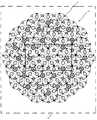
上記原映像枠をコピーし、複数の原映像枠(2n+1)を作り、2nθ(n=整数<p)回転させる。また、反転映像枠をコピーし、複数の反転映像枠(2n)を作り、2nθ(n=整数<p)回転させる。上記の過程で得られた2p個の映像枠の共通の頂点Oを一致させて重ね合わせた円盤状の映像枠群を映像枠群Aとする。この映像枠群Aをモニターの画面1のサイズの数倍の大きさの作業フィールド3の上にモザイクのように並べ、相対位置関係を固定し、この映像枠群Aによる万華鏡映像のパターン7をテレビモニターの画面の背景画面8の上層に映し出し、これに動画の映像データを取り込み、適宜に拡大、縮小、移動、回転させ、その他フィルターを掛けて映像効果を与えることにより、円盤状のpポイント2ミラーの様々な万華鏡映像7‘を作り出す。
図6は、モニターの画面1の背景8を黒くして5ポイント2ミラーの万華鏡映像を映し出した状況である。In the first preferred embodiment for carrying out the invention shown in FIG. 1 to FIG. 6, 1 is a monitor screen, 2 is a video sent from a video camera or a video recording device displayed on the monitor screen. It is.
4 is a video frame that can capture the video data of the video shown on the monitor, and associates the captured video data with the video frame, and moves, rotates, flips, enlarges, reduces, copies, cuts, etc. along with the video frame. Editing processing is possible, and the shape of the image frame is an isosceles triangle oab (o is the included angle) having an included angle θ360 ° / 2p (p = number of points), and this is the original image frame. A video frame that is inverted with one side oa of the
The original video frame is copied to create a plurality of original video frames (2n + 1) and rotated by 2nθ (n = integer <p). Also, the inverted video frame is copied to create a plurality of inverted video frames (2n) and rotated by 2nθ (n = integer <p). A disc-shaped video frame group obtained by overlapping and overlapping the common vertices O of the 2p video frames obtained in the above process is referred to as a video frame group A. This image frame group A is arranged like a mosaic on the
FIG. 6 shows a situation in which the
図7ないし図10示す発明を実施するための最良の第2の実施の形態において、作業フィールド3の中央に並べた円盤状の映像枠群A7を1次映像とし、その映像枠群A7の周囲に、映像枠群A7をコピーした2p個の複数の映像枠群Aを、1次映像の中心から半径2×oa×cos(θ/2)の円周上にあり、それぞれnθ(n=整数<p)回転し、辺abを共有して映像枠群A7と接するように並べた映像枠群を映像枠群B9とし、2次映像とする。さらに、映像枠群B9を構成する映像枠群Aの一つ一つの周囲に、映像群A7をコピーした2p×2p個の複数の映像枠群Aを、映像枠群B9を構成する映像枠群Aの中心から半径2×oa×cos(θ/2)の円周上にあり、それぞれnθ(n=整数<p)回転し、辺abを共有して映像枠群Aと接するように並べた映像枠群を映像枠群C10とし、3次映像とする。
以下、同様の作業を繰り返すことにより、1次映像を中心にm次映像へと無限に広がっていく。作業フィールド3の上にモザイク状に並べられ、反射次数が高くなって重なる部分は順次上に重ね、作業フィールドに対する相対位置関係を固定し、これを表裏反転し、重なって下に隠れ表から見えない反射次数の高い映像枠を廃棄し、この映像枠群による万華鏡映像のパターン11をテレビモニターの画面1に映し出し、これに動画の映像データを取り込み、適宜に拡大、縮小、移動、回転させ、その他フィルターを掛けて映像効果を与えることにより、Pポイント3ミラーの様々な万華鏡映像11‘を作り出す。
図10は、モニターの画面1に、5ポイント3ミラーの万華鏡映像を映し出した状況である。In the second preferred embodiment for carrying out the invention shown in FIGS. 7 to 10, a disc-shaped image frame group A7 arranged in the center of the
Thereafter, by repeating the same operation, the primary video is spread infinitely to the m-th video. Overlaying the
FIG. 10 shows a situation where a kaleidoscope image of 5 points and 3 mirrors is projected on the
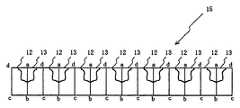
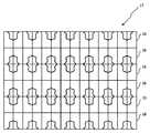
図11ないし図15示す発明を実施するための最良の第3の実施の形態において、モニター1に映る動画の映像データを取り込むことができる映像枠であって、取り込んだ映像データ14を映像枠に関連付け、映像枠と一緒に移動、回転、反転、拡大、縮小、コピー、カットなどの編集加工が可能であり、映像枠の形状が、矩形であって、これを原映像枠12とし、この原映像枠12の一辺abを対称軸として反転した映像枠を反転映像枠13とする。
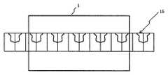
コピーした複数の原映像枠12と反転映像枠13を、映像の反射の原理に基づいて、かつミラー構成により特定される映像のパターンに合わせ、モニター画面1のサイズの数倍の大きさの作業フィールド3の上にストリップ状に交互に並べ、相対位置関係を固定し、この映像枠群による万華鏡映像のパターン15をテレビモニターの画面1の背景画面8の上層に映し出し、これに動画の映像データ14を取り込み、適宜に拡大、縮小、移動、回転させ、その他フィルターを掛けて映像効果を与えることにより、4角4ミラーの様々な万華鏡映像15‘を作り出す。
図15は、モニターの画面1の背景8を黒くして4角2ミラーの万華鏡映像を映し出した状況である。In the third preferred embodiment for practicing the invention shown in FIGS. 11 to 15, a video frame capable of capturing video data of a moving image shown on the
Work of several times the size of the
FIG. 15 shows a situation in which the
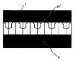
図16ないし図18示す発明を実施するための最良の第4の実施の形態において、作業フィールド3の中央に並べたストリップ状の映像枠群15を1次映像とし、反転した映像枠群16を2次映像とし、1次映像と2次映像を交互に並べ、相対位置関係を固定し、この映像枠群による万華鏡映像のパターン17をテレビモニターの画面1の背景画面8の上層に映し出し、これに動画の映像データを取り込み、適宜に拡大、縮小、移動、回転させ、その他フィルターを掛けて映像効果を与えることにより、4角4ミラーの様々な万華鏡映像17‘を作り出す。
図18は、モニターの画面1に、4角4ミラーの様々な万華鏡映像17‘を映し出した状況である。In the fourth preferred embodiment for carrying out the invention shown in FIGS. 16 to 18, the strip-shaped
FIG. 18 shows a situation in which
1、モニターの画面 2、ビデオカメラもしくは映像記録装置から送られてきた映像 3、作業フィールド 4、原映像枠 5、反転映像枠 6、映像枠に取り込まれた映像 7、映像枠群Aのパターン 7‘、見やすく調整した映像枠群Aのパターン 8、モニターの地の色 9、映像枠群Bのパターン 10、映像枠群Cのパターン 11、映像枠群A〜Cまでの映像枠群を複合した映像枠群のパターン 11’、見やすく調整した映像枠群のパターン 12、原映像枠 13、反転映像枠 14、映像枠に取り込まれた映像 15、ストリップ状に展開させた映像枠群のパターン 15‘、見やすく調整した映像枠群のパターン 16、1次映像枠群のパターンを反転させた2次映像枠群のパターン 17、1次映像枠群と2次映像枠群のパターンを交互に配置し、面として展開させた複合パターン 17‘、見やすく調整した複合パターン。1, monitor
Claims (5)
Translated fromJapanese以下、同様の作業を繰り返すことにより、1次映像を中心にm次映像へと無限に広がっていく。作業フィールドの上にモザイク状に並べられ、反射次数が高くなって重なる部分は順次上から重ね、作業フィールドに対する相対位置関係を固定し、これを表裏反転し、重なって下に隠れ表から見えない反射次数の高い映像枠を廃棄し、この映像枠群による万華鏡映像のパターンをテレビモニターの画面に映し出し、これに動画の映像データを取り込み、適宜に拡大、縮小、移動、回転させ、その他フィルターを掛けて映像効果を与えることにより、Pポイント3ミラーの様々な万華鏡映像を作り出すことを特徴とする請求項1および請求項2記載の万華鏡映像生成プログラム。Further, a disk-shaped video frame group A arranged in the center of the work field is set as a primary video, and a plurality of 2p video frame groups A obtained by copying the video frame group A are provided around the video frame group A as 1 They are on the circumference of radius 2 × oa × cos (θ / 2) from the center of the next video, respectively rotated by nθ (n = integer <p), and arranged so as to touch video frame group A while sharing side ab The selected video frame group is set as a video frame group B, which is a secondary video. Further, a plurality of 2p × 2p video frame groups A obtained by copying the video group A around each of the video frame groups A constituting the video frame group B are combined with the video frame group constituting the video frame group B. They are on the circumference of radius 2 × oa × cos (θ / 2) from the center of A, respectively rotated by nθ (n = integer <p), and arranged so as to be in contact with video frame group A by sharing side ab The video frame group is a video frame group C, and is a tertiary video.
Thereafter, by repeating the same operation, the primary video is spread infinitely to the m-th video. Overlapping parts that are arranged in a mosaic pattern on the work field and have higher reflection orders are sequentially stacked from the top, fixing the relative positional relationship with the work field, turning it upside down, and overlapping it so that it cannot be seen from the hidden table below Discard the video frame with high reflection order, project the kaleidoscope image pattern of this image frame group on the screen of the TV monitor, capture the video data of the video to this, enlarge, reduce, move, rotate, etc. as appropriate, and filter other 3. The kaleidoscope image generation program according to claim 1, wherein various kaleidoscope images of a P-point 3 mirror are created by applying a video effect.
Priority Applications (1)
| Application Number | Priority Date | Filing Date | Title |
|---|---|---|---|
| JP2012186981AJP2014035766A (en) | 2012-08-09 | 2012-08-09 | Kaleidoscope image generation program |
Applications Claiming Priority (1)
| Application Number | Priority Date | Filing Date | Title |
|---|---|---|---|
| JP2012186981AJP2014035766A (en) | 2012-08-09 | 2012-08-09 | Kaleidoscope image generation program |
Publications (1)
| Publication Number | Publication Date |
|---|---|
| JP2014035766Atrue JP2014035766A (en) | 2014-02-24 |
Family
ID=50284701
Family Applications (1)
| Application Number | Title | Priority Date | Filing Date |
|---|---|---|---|
| JP2012186981APendingJP2014035766A (en) | 2012-08-09 | 2012-08-09 | Kaleidoscope image generation program |
Country Status (1)
| Country | Link |
|---|---|
| JP (1) | JP2014035766A (en) |
Cited By (18)
| Publication number | Priority date | Publication date | Assignee | Title |
|---|---|---|---|---|
| CN110276817A (en)* | 2019-06-28 | 2019-09-24 | 北京金山安全软件有限公司 | Method and device for making picture and electronic equipment |
| KR20210104157A (en)* | 2017-05-12 | 2021-08-24 | 애플 인크. | Context-specific user interfaces |
| US11372659B2 (en) | 2020-05-11 | 2022-06-28 | Apple Inc. | User interfaces for managing user interface sharing |
| US11442414B2 (en) | 2020-05-11 | 2022-09-13 | Apple Inc. | User interfaces related to time |
| US11526256B2 (en) | 2020-05-11 | 2022-12-13 | Apple Inc. | User interfaces for managing user interface sharing |
| US11550465B2 (en) | 2014-08-15 | 2023-01-10 | Apple Inc. | Weather user interface |
| US11580867B2 (en) | 2015-08-20 | 2023-02-14 | Apple Inc. | Exercised-based watch face and complications |
| US11694590B2 (en) | 2020-12-21 | 2023-07-04 | Apple Inc. | Dynamic user interface with time indicator |
| US11720239B2 (en) | 2021-01-07 | 2023-08-08 | Apple Inc. | Techniques for user interfaces related to an event |
| US11740776B2 (en) | 2014-08-02 | 2023-08-29 | Apple Inc. | Context-specific user interfaces |
| US11921992B2 (en) | 2021-05-14 | 2024-03-05 | Apple Inc. | User interfaces related to time |
| US11977411B2 (en) | 2018-05-07 | 2024-05-07 | Apple Inc. | Methods and systems for adding respective complications on a user interface |
| US12019862B2 (en) | 2015-03-08 | 2024-06-25 | Apple Inc. | Sharing user-configurable graphical constructs |
| US12045014B2 (en) | 2022-01-24 | 2024-07-23 | Apple Inc. | User interfaces for indicating time |
| US12175065B2 (en) | 2016-06-10 | 2024-12-24 | Apple Inc. | Context-specific user interfaces for relocating one or more complications in a watch or clock interface |
| US12182373B2 (en) | 2021-04-27 | 2024-12-31 | Apple Inc. | Techniques for managing display usage |
| US12265703B2 (en) | 2019-05-06 | 2025-04-01 | Apple Inc. | Restricted operation of an electronic device |
| US12373079B2 (en) | 2019-09-09 | 2025-07-29 | Apple Inc. | Techniques for managing display usage |
- 2012
- 2012-08-09JPJP2012186981Apatent/JP2014035766A/enactivePending
Cited By (32)
| Publication number | Priority date | Publication date | Assignee | Title |
|---|---|---|---|---|
| US12430013B2 (en) | 2014-08-02 | 2025-09-30 | Apple Inc. | Context-specific user interfaces |
| US11740776B2 (en) | 2014-08-02 | 2023-08-29 | Apple Inc. | Context-specific user interfaces |
| US11550465B2 (en) | 2014-08-15 | 2023-01-10 | Apple Inc. | Weather user interface |
| US12229396B2 (en) | 2014-08-15 | 2025-02-18 | Apple Inc. | Weather user interface |
| US11922004B2 (en) | 2014-08-15 | 2024-03-05 | Apple Inc. | Weather user interface |
| US12019862B2 (en) | 2015-03-08 | 2024-06-25 | Apple Inc. | Sharing user-configurable graphical constructs |
| US11908343B2 (en) | 2015-08-20 | 2024-02-20 | Apple Inc. | Exercised-based watch face and complications |
| US12243444B2 (en) | 2015-08-20 | 2025-03-04 | Apple Inc. | Exercised-based watch face and complications |
| US11580867B2 (en) | 2015-08-20 | 2023-02-14 | Apple Inc. | Exercised-based watch face and complications |
| US12175065B2 (en) | 2016-06-10 | 2024-12-24 | Apple Inc. | Context-specific user interfaces for relocating one or more complications in a watch or clock interface |
| KR20210104157A (en)* | 2017-05-12 | 2021-08-24 | 애플 인크. | Context-specific user interfaces |
| US11775141B2 (en) | 2017-05-12 | 2023-10-03 | Apple Inc. | Context-specific user interfaces |
| KR102408802B1 (en) | 2017-05-12 | 2022-06-13 | 애플 인크. | Context-specific user interfaces |
| US11977411B2 (en) | 2018-05-07 | 2024-05-07 | Apple Inc. | Methods and systems for adding respective complications on a user interface |
| US12265703B2 (en) | 2019-05-06 | 2025-04-01 | Apple Inc. | Restricted operation of an electronic device |
| CN110276817A (en)* | 2019-06-28 | 2019-09-24 | 北京金山安全软件有限公司 | Method and device for making picture and electronic equipment |
| CN110276817B (en)* | 2019-06-28 | 2023-12-19 | 北京朱比特科技有限公司 | Picture making method and device and electronic equipment |
| US12373079B2 (en) | 2019-09-09 | 2025-07-29 | Apple Inc. | Techniques for managing display usage |
| US11372659B2 (en) | 2020-05-11 | 2022-06-28 | Apple Inc. | User interfaces for managing user interface sharing |
| US11442414B2 (en) | 2020-05-11 | 2022-09-13 | Apple Inc. | User interfaces related to time |
| US12422977B2 (en) | 2020-05-11 | 2025-09-23 | Apple Inc. | User interfaces with a character having a visual state based on device activity state and an indication of time |
| US11842032B2 (en) | 2020-05-11 | 2023-12-12 | Apple Inc. | User interfaces for managing user interface sharing |
| US12099713B2 (en) | 2020-05-11 | 2024-09-24 | Apple Inc. | User interfaces related to time |
| US12008230B2 (en) | 2020-05-11 | 2024-06-11 | Apple Inc. | User interfaces related to time with an editable background |
| US11822778B2 (en) | 2020-05-11 | 2023-11-21 | Apple Inc. | User interfaces related to time |
| US11526256B2 (en) | 2020-05-11 | 2022-12-13 | Apple Inc. | User interfaces for managing user interface sharing |
| US12333123B2 (en) | 2020-05-11 | 2025-06-17 | Apple Inc. | User interfaces for managing user interface sharing |
| US11694590B2 (en) | 2020-12-21 | 2023-07-04 | Apple Inc. | Dynamic user interface with time indicator |
| US11720239B2 (en) | 2021-01-07 | 2023-08-08 | Apple Inc. | Techniques for user interfaces related to an event |
| US12182373B2 (en) | 2021-04-27 | 2024-12-31 | Apple Inc. | Techniques for managing display usage |
| US11921992B2 (en) | 2021-05-14 | 2024-03-05 | Apple Inc. | User interfaces related to time |
| US12045014B2 (en) | 2022-01-24 | 2024-07-23 | Apple Inc. | User interfaces for indicating time |
Similar Documents
| Publication | Publication Date | Title |
|---|---|---|
| JP2014035766A (en) | Kaleidoscope image generation program | |
| US10063822B2 (en) | Tri-surface image projection system and method | |
| US6665003B1 (en) | System and method for generating and displaying panoramic images and movies | |
| Weissig et al. | The ultimate immersive experience: panoramic 3D video acquisition | |
| CN104869376B (en) | Multi-image and multi-pixel level geometric correction method for video fusion | |
| TWI683569B (en) | Panorama video compression method and device | |
| TW200526987A (en) | Display device and display method | |
| CN101183208A (en) | Panoramic displaying device and panoramic displaying method | |
| CN100552539C (en) | A method for making a three-dimensional film image with a ring screen | |
| JP2009010915A (en) | Video display method and video system | |
| CN111105735A (en) | An all-solid-state holographic projector | |
| Liao et al. | Scalable high-resolution integral videography autostereoscopic display with a seamless multiprojection system | |
| CN105100759A (en) | Screen projection system, method and device | |
| TW200540549A (en) | Display device | |
| US6650396B2 (en) | Method and processor for stereo cylindrical imaging | |
| CN203457260U (en) | Three-dimensional (3D) holographic integrated rear projection apparatus | |
| CN108572460B (en) | image display system | |
| CN204906591U (en) | Screen projecting system and device | |
| Schreer et al. | Geometrical design concept for panoramic 3D video acquisition | |
| TW201818142A (en) | 360 degree multi-view projection imaging device | |
| Maniello | Improvements and implementations of the spatial augmented reality applied on scale models of cultural goods for visual and communicative purpose | |
| JP2020137108A (en) | Projection display equipment and projecting method | |
| JP2019518977A (en) | Reflective surround display system | |
| JP3600422B2 (en) | Stereo image display method and apparatus | |
| Zheng et al. | A virtual environment making method for cave system |