JP2014016117A - Instantaneous hot water supply system - Google Patents
Instantaneous hot water supply systemDownload PDFInfo
- Publication number
- JP2014016117A JP2014016117AJP2012154506AJP2012154506AJP2014016117AJP 2014016117 AJP2014016117 AJP 2014016117AJP 2012154506 AJP2012154506 AJP 2012154506AJP 2012154506 AJP2012154506 AJP 2012154506AJP 2014016117 AJP2014016117 AJP 2014016117A
- Authority
- JP
- Japan
- Prior art keywords
- hot water
- water supply
- line
- valve means
- supply line
- Prior art date
- Legal status (The legal status is an assumption and is not a legal conclusion. Google has not performed a legal analysis and makes no representation as to the accuracy of the status listed.)
- Granted
Links
- XLYOFNOQVPJJNP-UHFFFAOYSA-NwaterSubstancesOXLYOFNOQVPJJNP-UHFFFAOYSA-N0.000titleclaimsabstractdescription676
- 238000011144upstream manufacturingMethods0.000claimsabstractdescription50
- 238000010079rubber tappingMethods0.000claimsabstractdescription8
- 238000001514detection methodMethods0.000claimsdescription39
- 238000010792warmingMethods0.000claimsdescription34
- 238000009413insulationMethods0.000claimsdescription14
- 238000010438heat treatmentMethods0.000claims2
- 238000002485combustion reactionMethods0.000description25
- 235000001537Ribes X gardonianumNutrition0.000description15
- 235000001535Ribes X utileNutrition0.000description15
- 235000016919Ribes petraeumNutrition0.000description15
- 244000281247Ribes rubrumSpecies0.000description15
- 235000002355Ribes spicatumNutrition0.000description15
- 238000004891communicationMethods0.000description6
- 238000000034methodMethods0.000description6
- 238000011084recoveryMethods0.000description6
- BWRHOYDPVJPXMF-UHFFFAOYSA-Ncis-CaranNatural productsC1C(C)CCC2C(C)(C)C12BWRHOYDPVJPXMF-UHFFFAOYSA-N0.000description5
- TUWJQNVAGYRRHA-UHFFFAOYSA-NMenadiol dibutyrateChemical compoundC1=CC=C2C(OC(=O)CCC)=CC(C)=C(OC(=O)CCC)C2=C1TUWJQNVAGYRRHA-UHFFFAOYSA-N0.000description4
- 238000010586diagramMethods0.000description3
- KNZUAMRYQXIWSR-RUAUHYFQSA-NcuranChemical compoundC1=CC=C2[C@@]3([C@@H]4C5)CCN4C[C@@H](CC)[C@H]5[C@@H](C)[C@@H]3NC2=C1KNZUAMRYQXIWSR-RUAUHYFQSA-N0.000description2
- 238000007599dischargingMethods0.000description2
- 230000005855radiationEffects0.000description2
- 229910001220stainless steelInorganic materials0.000description2
- 239000010935stainless steelSubstances0.000description2
Images


Landscapes
- Domestic Hot-Water Supply Systems And Details Of Heating Systems (AREA)
Abstract
Description
Translated fromJapanese本発明は、カランなどを開栓したときに開栓当初から温水が出湯する即湯給湯システムに関する。 The present invention relates to an immediate hot water supply system in which hot water is discharged from the beginning of opening when a caran or the like is opened.
一般的に、給湯システムは、熱源機などの温水供給源と、温水を出湯する出湯手段(例えば、カランなど)と、温水供給源からの温水を出湯手段に導く給湯ラインとを備えている。このような給湯システムでは、出湯手段を開栓すると、温水供給源からの温水が給湯ラインを通して送給されて出湯手段から出湯するが、温水供給源からの温水が出湯手段に到達するまでは給湯ライン内に存在する水が出湯手段から流れ、冬の時期などにおいては、このような水は冷たいために使用することなく流して捨てていた。 In general, a hot water supply system includes a hot water supply source such as a heat source machine, a hot water supply means for discharging hot water (for example, a curan), and a hot water supply line for guiding the hot water from the hot water supply source to the hot water supply means. In such a hot water supply system, when the hot water supply means is opened, the hot water from the hot water supply source is supplied through the hot water supply line and discharged from the hot water supply means, but the hot water from the hot water supply source reaches the hot water supply means until it reaches the hot water supply means. The water present in the line flowed from the hot water supply means, and in the winter season, such water was thrown away without being used because it was cold.
そこで、この水を無駄に捨てるのを少なくするために、出湯手段(例えば、カランなど)の近くに温水を出湯するための温水タンクを設けた即湯給湯システムが提案されている(例えば、特許文献1参照)。この即湯給湯システムでは、給湯ラインに温水タンクが配設され、この温水タンク内に加熱ヒータが設けられ、温水タンク内の水が加熱ヒータにより温められる。 Therefore, in order to reduce the wasteful disposal of this water, there has been proposed an instant hot water supply system provided with a hot water tank near the hot water supply means (for example, Karan) for hot water to be discharged (for example, patents). Reference 1). In this hot water supply system, a hot water tank is provided in the hot water supply line, a heater is provided in the hot water tank, and water in the hot water tank is heated by the heater.
この即湯給湯システムにおいては、温水供給源からの温水は給湯ラインの上流側部を介して温水タンクの底部に供給され、温水タンク内の温水は給湯ラインの下流側部を介して出湯手段に送給され、また給湯ラインの上流側部とその下流側部とがバイパスラインを介して接続されている。従って、出湯手段を開栓すると、給湯ラインの上流側部内の水が温水タンクの底部に送給され、かかる送給によって押し上げられた温水が給湯ラインの下流側部を通して出湯手段に送給され、このようにして開栓当初においては温水タンク内の温水が出湯手段に送給され、かく送給される温水にバイパスラインを通して流れる水が混合されて出湯手段から出湯する。そして、温水供給源からの温水がバイパスラインまで到達すると、温水供給源からの温水が温水タンクからの温水に混合され、かく混合された温水が出湯手段に送給され、また温水供給源からの温水が温水タンクまで到達すると、この温水がバイパスライン及び温水タンクを通して出湯手段に送給される。 In this hot water supply system, hot water from a hot water supply source is supplied to the bottom of the hot water tank via the upstream side of the hot water supply line, and the hot water in the hot water tank is supplied to the hot water supply means via the downstream side of the hot water supply line. In addition, the upstream side portion and the downstream side portion of the hot water supply line are connected via a bypass line. Therefore, when the hot water supply means is opened, the water in the upstream side of the hot water supply line is supplied to the bottom of the hot water tank, and the hot water pushed up by such supply is supplied to the hot water supply means through the downstream side of the hot water supply line, In this way, at the beginning of opening, the hot water in the hot water tank is supplied to the hot water discharge means, and the hot water thus supplied is mixed with the water flowing through the bypass line and discharged from the hot water discharge means. When the hot water from the hot water supply source reaches the bypass line, the hot water from the hot water supply source is mixed with the hot water from the hot water tank, and the mixed hot water is supplied to the hot water supply means, and from the hot water supply source. When the hot water reaches the hot water tank, the hot water is supplied to the hot water supply means through the bypass line and the hot water tank.
しかしながら、従来の温水タンクを備えた即湯給湯システムでは、温水タンクに加熱ヒータが内蔵されているために、その消費電力が大きく、既設の給湯システムなどに取り付けようとすると、簡単に取り付けることが難しくなる。 However, a conventional hot water supply system equipped with a hot water tank has a built-in heater in the hot water tank, and thus consumes a large amount of power. It becomes difficult.
本発明の目的は、閉栓時に給湯ラインに残存する温水を回収し、この回収した温水を開栓時に利用するようにした即湯給湯システムを提供することである。 An object of the present invention is to provide an instant hot water supply system that recovers hot water remaining in a hot water supply line when closing and uses the recovered hot water when opening.
また、本発明の他の目的は、温水出湯中に給湯ラインを流れる温水の一部を回収し、この回収した温水を開栓時に利用するようにした即湯給湯システムを提供することである。 Another object of the present invention is to provide an instant hot water supply system in which a part of hot water flowing through a hot water supply line is recovered during hot water hot water supply, and the recovered hot water is used at the time of opening.
本発明の請求項1に記載の即湯給湯システムは、温水を供給する温水供給源と、前記温水供給源からの温水が給湯ラインを介して供給される出湯手段と、前記給湯ラインの一部をバイパスして設けられたバイパスラインと、前記バイパスラインに配設された即湯保温ポットと、前記給湯ラインを流れる水又は温水の流れを切り換えるために前記給湯ラインに配設された切換弁手段と、を備えており、
前記出湯手段を開栓したときには、前記切換弁手段が第1切換状態に保持され、前記温水供給源からの温水が前記切換弁手段に送給されるまでの間にわたって、前記給湯ラインの上流側部の水が前記切換弁手段及び前記バイパス流路の上流側部を通して前記即湯保温ポット内に送給され、前記即湯保温ポット内の温水が前記バイパス流路の下流側部及び前記給湯ラインの下流側部を通して前記出湯手段に送給され、そして、前記温水供給源からの温水が前記切換弁手段まで送給されると、前記切換弁手段が第2切換状態に保持され、前記温水供給源からの温水が前記給湯ラインの前記上流側部、前記切換弁手段及び前記給湯ラインの前記下流側部を通して前記出湯手段に送給され、その後前記出湯手段を閉栓すると、前記給湯ラインの前記上流側部に残存する温水が前記切換弁手段及び前記バイパス流路の前記下流側部を通して前記即湯保温ポットに回収されることを特徴とする。The instant hot water supply system according to claim 1 of the present invention includes a hot water supply source for supplying hot water, hot water supply means for supplying hot water from the hot water supply source via a hot water supply line, and a part of the hot water supply line. A bypass line provided to bypass the hot water supply pot, an instant hot water warming pot provided in the bypass line, and a switching valve means provided in the hot water supply line for switching the flow of water or hot water flowing in the hot water supply line And,
When the hot water supply means is opened, the switching valve means is maintained in the first switching state, and the upstream side of the hot water supply line until hot water from the hot water supply source is supplied to the switching valve means. Water is fed into the hot water warming pot through the switching valve means and the upstream side of the bypass flow path, and the hot water in the quick hot water warming pot is fed to the downstream side of the bypass flow path and the hot water supply line. When the hot water from the hot water supply source is supplied to the switching valve means, the switching valve means is held in the second switching state, and the hot water supply is supplied. When hot water from a source is supplied to the hot water outlet through the upstream side of the hot water supply line, the switching valve means and the downstream side of the hot water supply line, and then the hot water outlet is closed, the upper side of the hot water supply line Wherein the hot water remaining in the side is recovered in the immediate water insulation pot through said downstream portion of said switching valve means and the bypass passage.
また、本発明の請求項2に記載の即湯給湯システムでは、前記即湯保温ポットには排水ラインが設けられ、前記排水ラインに流量制限開閉弁手段が設けられており、前記出湯手段を閉栓すると、前記流量制限開閉弁手段が開状態となり、前記即湯保温ポット内の水が前記排水ライン及び前記流量制限開閉弁手段を通して排水されるとともに、前記流量制限開閉弁手段によって水の排水流量が制限され、これによって、前記温水供給源が作動することなく前記給湯ラインの前記上流側部に残存する温水が前記切換弁手段及び前記バイパス流路の前記下流側部を通して前記即湯保温ポットに回収されることを特徴とする。 Further, in the immediate hot water supply system according to
また、本発明の請求項3に記載の即湯給湯システムでは、前記給湯ラインには、前記切換弁手段に関連して、前記給湯ラインを流れる水の温度を検知するための第1温度検知手段及び前記給湯ラインの水の流れを検知するための流量検知手段が設けられており、前記出湯手段を開栓して前記流量検知手段が所定流量以上の水の流れを検知すると、前記切換弁手段が前記第1切換状態に保持され、そして、前記第1温度検知手段が前記温水供給手段からの温水を検知すると、前記切換弁手段が前記第2切換状態に保持され、その後前記出湯手段を閉栓して前記流量検知手段が所定流量以上の水の流れを検知しなくなると、前記流量制限開閉弁が開状態に保持されることを特徴とする。 Further, in the instant hot water supply system according to claim 3 of the present invention, the hot water supply line includes a first temperature detection means for detecting a temperature of water flowing through the hot water supply line in relation to the switching valve means. And a flow rate detecting means for detecting the flow of water in the hot water supply line. When the outlet means is opened and the flow rate detecting means detects a flow of water above a predetermined flow rate, the switching valve means Is held in the first switching state, and when the first temperature detecting means detects hot water from the hot water supply means, the switching valve means is held in the second switching state, and then the hot water means is closed. When the flow rate detecting means stops detecting a flow of water at a predetermined flow rate or higher, the flow rate limiting on / off valve is held open.
また、本発明の請求項4に記載の即湯給湯システムでは、前記即湯保温ポット内には、温水の温度を検知するための第2温度検知手段が配設され、前記流量制限開閉弁が開状態に保持された後前記第2温度検知手段が温水を検知すると、前記流量制限開閉弁が閉状態に保持されることを特徴とする。 Further, in the instant hot water supply system according to
また、本発明の請求項5に記載の即湯給湯システムは、温水を供給する温水供給源と、前記温水供給源からの温水が給湯ラインを介して供給される出湯手段と、前記給湯ラインの一部をバイパスして設けられたバイパスラインと、前記バイパスラインに配設された即湯保温ポットと、前記給湯ラインを流れる水又は温水の流れを切り換えるために前記給湯ラインに配設された熱感式切換弁手段と、を備えており、
前記出湯手段を開栓したときには、前記熱感式切換弁手段が第1切換状態に保持され、前記温水供給源からの温水が前記熱感式切換弁手段に送給されるまでの間にわたって、前記給湯ラインの上流側部の水が前記熱感式切換弁手段及び前記バイパスラインの上流側部を通して前記即湯保温ポット内に送給され、前記即湯保温ポット内の温水が前記バイパスラインの下流側部及び前記給湯ラインの下流側部を通して前記出湯手段に送給され、そして、前記温水供給源からの温水が前記熱感式切換弁手段まで送給されると、前記熱感式切換弁手段が第2切換状態に保持され、前記温水供給源からの温水が前記給湯ラインの前記上流側部、前記切換弁手段及び前記給湯ラインの前記下流側部を通して前記出湯手段に送給され、温水供給手段からの温水出湯中に、前記給湯ラインの前記下流側部を流れる温水の一部が前記バイパスラインの前記下流側部を通して前記即湯保温ポットに回収されることを特徴とする。An instant hot water supply system according to claim 5 of the present invention is a hot water supply source for supplying hot water, hot water supply means for supplying hot water from the hot water supply source via a hot water supply line, Heat provided in the hot water supply line to switch between a bypass line provided by bypassing a part, an instant hot water warming pot provided in the bypass line, and water or hot water flowing in the hot water supply line A sensitive switching valve means,
When the hot water discharge means is opened, the heat sensitive switching valve means is maintained in the first switching state, and the hot water from the hot water supply source is supplied to the heat sensitive switching valve means. Water on the upstream side of the hot water supply line is fed into the hot water warming pot through the heat sensitive switching valve means and the upstream side of the bypass line, and the hot water in the hot water warming pot is supplied to the bypass line. When the hot water from the hot water supply source is supplied to the hot water switching means through the downstream side and the downstream side of the hot water supply line, and when the hot water is supplied to the heat sensitive switching valve means, the heat sensitive switching valve Means is maintained in the second switching state, and hot water from the hot water supply source is supplied to the hot water supply means through the upstream side portion of the hot water supply line, the switching valve means, and the downstream side portion of the hot water supply line. Temperature from supply means During tapping, and a part of the hot water flowing through the downstream portion of the hot water supply line is collected in the immediate water insulation pot through the downstream portion of the bypass line.
更に、本発明の請求項6に記載の即湯給湯システムでは、前記即湯保温ポットには排水ラインが設けられ、前記排水ラインに熱感式流量制限開閉弁手段が設けられ、更に前記即湯保温ポットをバイパスして前記熱感式流量制限開閉弁手段を通して温水を流すための作動温水ラインが設けられており、前記温水供給源からの温水が前記作動温水ラインを流れて前記熱感式流量制限開閉弁が開状態になると、前記即湯保温ポット内の水が前記排水ライン及び前記熱感式流量制限開閉弁を通して排水されるとともに、前記熱感式流量制限開閉弁手段によって水の排水流量が制限され、これによって、前記給湯ラインの前記下流側部を流れる温水の一部が前記バイパスラインの前記下流側部を通して前記即湯保温ポットに回収されることを特徴とする。 Furthermore, in the instant hot water supply system according to
本発明の請求項1に記載の即湯給湯システムによれば、温水供給源と出湯手段(例えば、カランなど)との間の給湯ラインの一部をバイパスしてバイパスラインが設けられ、このバイパスラインに即湯保温ポットが配設されるとともに、この給湯ラインに切換弁手段が設けられる。出湯手段を開栓したときには、切換弁手段が第1切換状態に保持されるので、給湯ラインの上流側部の水が切換弁手段及びバイパスラインの上流側部を通して即湯保温ポット内に送給され、これによって、即湯保温ポット内の温水がバイパスラインの下流側部及び給湯ラインの下流側部を通して出湯手段に送給され、ほぼ開栓当初から温水を出湯することができる。そして、温水供給源からの温水が切換弁手段まで送給されると、切換弁手段が第2切換状態に保持されるので、温水供給源からの温水が給湯ラインの上流側部、切換弁手段及び給湯ラインの下流側部を通して出湯手段に送給され、温水供給源からの温水が送給された後はこの温水が出湯され、継続して温水を出湯することができる。その後、出湯手段を閉栓すると、給湯ラインの上流側部に残存する温水が切換弁手段及びバイパスラインの下流側部を通して即湯保温ポットに回収され、このようにすることによって、加熱ヒータなどを用いることなく温水を即湯保温ポットに貯めることができ、このように回収して貯めた温水を次の開栓時に有効に利用することができる。尚、即湯保温ポットとしては、断熱仕様のポットを用いることができる。 According to the instant hot water supply system of the first aspect of the present invention, a bypass line is provided by bypassing a part of the hot water supply line between the hot water supply source and the hot water supply means (for example, curan etc.). An instant hot water warming pot is provided in the line, and a switching valve means is provided in the hot water supply line. When the hot water supply means is opened, the switching valve means is held in the first switching state, so that the water on the upstream side of the hot water supply line is immediately fed into the hot water warming pot through the upstream side part of the switching valve means and the bypass line. Thus, the hot water in the hot water heat insulating pot is fed to the hot water outlet means through the downstream side portion of the bypass line and the downstream side portion of the hot water supply line, and the hot water can be discharged almost from the beginning. When the hot water from the hot water supply source is supplied to the switching valve means, the switching valve means is held in the second switching state, so that the hot water from the hot water supply source is upstream of the hot water supply line, the switching valve means. After the hot water is supplied from the hot water supply source through the downstream side of the hot water supply line to the hot water supply means, the hot water is discharged and the hot water can be discharged continuously. Thereafter, when the hot water supply means is closed, the hot water remaining in the upstream side portion of the hot water supply line is collected in the hot water heat-insulating pot through the switching valve means and the downstream side portion of the bypass line, and in this way, a heater is used. The hot water can be stored in the hot water insulation pot without any trouble, and the hot water collected and stored in this way can be used effectively at the next opening. In addition, as an instant hot water heat-insulating pot, a heat-insulating pot can be used.
また、本発明の請求項2に記載の即湯給湯システムによれば、即湯保温ポットに排水ラインが設けられ、この排水ラインに流量制限開閉弁手段が設けられている。出湯手段を閉栓すると、この流量制限開閉弁手段が開状態となるので、即湯保温ポット内の水が排水ラインを通して排水されるとともに、流量制限開閉弁手段によって水の排水流量が制限され、これによって、温水供給源が作動することなく給湯ラインの上流側部に残存する温水を即湯保温ポットに回収することができる。例えば、温水供給源として燃焼式熱源機を用いた場合、この熱源機では流量が燃焼下限流量よりも少ないときには燃焼して温水を生成することがなく、従って、流量制限開閉弁手段による排水流量がこの燃焼下限流量よりも少ない量となるように制限することによって、燃焼式熱源機が作動することなく温水を回収して貯めることができる。 According to the instant hot water supply system of
また、本発明の請求項3に記載の即湯給湯システムによれば、切換弁手段に関連して、給湯ラインに第1温度検知手段及び流量検知手段が設けられている。そして、出湯手段を開栓して流量検知手段が所定流量以上の水の流れを検知すると、切換弁手段が第1切換状態に保持されるので、即湯保温ポット内の温水を出湯することができる。また、第1温度検知手段が温水供給手段からの温水を検知すると、切換弁手段が第2切換状態に保持されるので、温水供給源からの温水が出湯され、出湯手段から継続して温水を出湯することができる。その後、出湯手段を閉栓して流量検知手段が所定流量以上の水の流れを検知しなくなると、流量制限開閉弁が開状態に保持されるので、給湯ラインの上流側部に残留する温水をバイパスラインの下流側部を通して即湯保温ポットに回収して貯めることができる。尚、流量検知手段が検知する所定流量は、例えば、燃焼式熱源機の燃焼下限流量に設定される。 According to the instant hot water supply system of the third aspect of the present invention, the first temperature detecting means and the flow rate detecting means are provided in the hot water supply line in relation to the switching valve means. And when the hot water discharge means is opened and the flow rate detection means detects the flow of water at a predetermined flow rate or higher, the switching valve means is held in the first switching state, so that the hot water in the hot water warming pot can be discharged quickly. it can. When the first temperature detecting means detects the hot water from the hot water supply means, the switching valve means is held in the second switching state, so that the hot water from the hot water supply source is discharged and the hot water is continuously supplied from the hot water supply means. You can take a bath. After that, when the hot water supply means is closed and the flow rate detection means no longer detects the flow of water above the predetermined flow rate, the flow rate restricting on / off valve is held open so that the hot water remaining on the upstream side of the hot water supply line is bypassed. It can be collected and stored in a hot water heat insulating pot through the downstream side of the line. The predetermined flow rate detected by the flow rate detection means is set to, for example, the combustion lower limit flow rate of the combustion heat source machine.
また、本発明の請求項4に記載の即湯給湯システムによれば、即湯保温ポット内の第2温度検知手段が温水を検知すると流量制限開閉弁が閉状態に保持されるので、即湯保温ポット内に温水が貯まると流量制限開閉弁が閉状態になり、給湯ラインに残存する温水の回収が終了する。 Further, according to the instant hot water supply system according to
また、本発明の請求項5に記載の即湯給湯システムによれば、給湯ラインの一部をバイパスしてバイパスラインが設けられ、このバイパスラインに即湯保温ポットが配設されているとともに、給湯ラインに熱感式切換弁手段が設けられる。出湯手段を開栓したときには、熱感式切換弁手段が第1切換状態に保持され、給湯ラインの上流側部の水が熱感式切換弁手段及びバイパスラインの上流側部を通して即湯保温ポット内に送給され、即湯保温ポット内の温水がバイパスラインの下流側部及び給湯ラインの下流側部を通して出湯手段に送給され、ほぼ開栓当初から温水を出湯することができる。そして、温水供給源からの温水が熱感式切換弁手段まで送給されると、熱感式切換弁手段が第2切換状態に保持されるので、温水供給源からの温水が給湯ラインの上流側部、熱感式切換弁手段及び給湯ラインの下流側部を通して出湯手段に送給され、継続して温水を出湯することができる。また、この温水供給手段からの温水出湯中においては、給湯ラインの下流側部を流れる温水の一部が即湯保温ポットに回収されるので、このようにしても加熱ヒータを用いることなく温水を即湯本ポットに回収して貯めることができる。更に、切換弁手段として熱を利用した熱感式切換弁手段を用いているので、配線などを必要とせずに設置することができ、既設の給湯システムにも容易に後付けすることができる。 According to the instant hot water supply system of claim 5 of the present invention, a bypass line is provided by bypassing a part of the hot water supply line, and an immediate hot water warming pot is provided in the bypass line. A heat sensitive switching valve means is provided in the hot water supply line. When the hot water supply means is opened, the heat sensitive switching valve means is held in the first switching state, and the water in the upstream side of the hot water supply line passes immediately through the heat sensitive switching valve means and the upstream side of the bypass line. The hot water in the hot water warming pot is fed to the hot water outlet means through the downstream side portion of the bypass line and the downstream side portion of the hot water supply line, and the hot water can be discharged almost from the beginning of opening. When hot water from the hot water supply source is supplied to the heat sensitive switching valve means, the heat sensitive switching valve means is maintained in the second switching state, so that the hot water from the hot water supply source is upstream of the hot water supply line. The hot water can be discharged continuously by being fed to the hot water outlet means through the side portion, the heat sensitive switching valve means and the downstream side portion of the hot water supply line. Further, in the hot water hot water supply from the hot water supply means, a part of the hot water flowing downstream of the hot water supply line is collected in the hot water heat insulating pot, so that the hot water is not used without using the heater. It can be collected and stored in an instant hot water pot. Furthermore, since the heat-sensitive switching valve means using heat is used as the switching valve means, it can be installed without the need for wiring or the like, and can be easily retrofitted to an existing hot water supply system.
更に、本発明の請求項6に記載の即湯給湯システムによれば、即湯保温ポットに排水ラインが設けられ、排水ラインに熱感式流量制限開閉弁手段が設けられ、更に熱感式流量制限開閉弁手段を通して温水を流すための作動温水ラインが設けられている。そして、温水供給源からの温水が作動温水ラインを流れると、この温水によって熱感式流量制限開閉弁手段が加温されて開状態となり、即湯保温ポット内の水が排水ラインを通して排水されるとともに、感熱式流量制限開閉弁手段によって水の排水流量が制限され、これによって、給湯ラインの下流側部を流れる温水の一部を即湯保温ポットに回収して貯めることができる。 Further, according to the instant hot water supply system according to
以下、添付図面を参照して、本発明に従う即湯給湯システムの各種実施形態について説明する。 Hereinafter, various embodiments of an instant hot water supply system according to the present invention will be described with reference to the accompanying drawings.
〔第1の実施形態〕
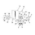
図1〜図3を参照して、第1の実施形態の即湯給湯システムについて説明する。図1において、図示の即湯給湯システムは、温水を供給するための温水供給源2と、温水を出湯する出湯手段4と、温水供給源2からの温水を出湯手段4に導く給湯ライン6とを備えている。この形態では、温水供給源2は燃焼式の熱源機8から構成され、この熱源機8は燃焼バーナ(図示せず)などを備え、燃焼バーナの燃焼によって温水を生成する。[First Embodiment]
With reference to FIGS. 1 to 3, a hot water supply system according to the first embodiment will be described. In FIG. 1, the illustrated hot water supply system includes a hot
この給湯ライン6には切換弁手段10が配設され、この形態では、切換弁手段10が三方切換弁12から構成されている。また、給湯ライン6の一部(具体的には、三方切換弁12が配設された部位)をバイパスしてバイパスライン16が設けられ、このバイパスライン16に即湯保温ポット14が配設されている。即湯保温ポット14は断熱仕様の保温ポット(例えば、真空層を有するステンレス製保温ポット、真空層及び空気層を有するステンレス製保温ポットなど)から構成される。この即湯保温ポット14は、内容量が例えば1.5〜3.0L程度のものを用いることができる。 The hot
具体的には、三方切換弁12の第1ポート18にはバイパスライン16の上流側部20の一端側が接続され、その他端側が即湯保温ポット14の底部に接続されている。また、三方切換弁12の第2ポート22には給湯ライン6の上流側部24の一端側が接続され、その他端側が熱源機8に接続されている。また、三方切換弁12の第3ポート26には給湯ライン6の下流側部28の一端側が接続され、その他端側が出湯手段4に接続されている。図示の例では、出湯手段4が二つ設けられ、給湯ライン6の下流側部28がこれら出湯手段4に接続されている。尚、出湯手段4については、一つ又は三つ以上設けるようにしてもよく、出湯手段4としては、例えばカラン30などが用いられる。 Specifically, one end side of the
更に、バイパスライン16の下流側部31の一端側が即湯保温ポット14の上端部に接続され、その他端側が給湯ライン6の下流側部28に接続されている。この即湯保温ポット14は、出湯手段4に近接して設けるのが望ましく、このように設けることにより、出湯手段4を開栓したときに即湯保温ポット14からの温水がすぐに出湯するようになる。 Furthermore, one end side of the
このように構成されているので、三方切換弁12が第1切換状態にあるときには、第2ポート22と第1ポート18とが連通状態となり、給湯ライン6の上流側部24を流れる水は三方切換弁12及びバイパスライン16の上流側部20を通して即湯保温ポット14に送給される(図2(a)参照)。また、三方切換弁12が第2切換状態にあるときには、第2ポート22と第3ポート26とが連通状態となり、後述するように、給湯ライン6の上流側部を流れる温水が三方切換弁12及び給湯ライン6の下流側部28を通して出湯手段4に送給され(図2(b)参照)、又は給湯ライン6の上流側部24に残留する温水が三方切換弁12、給湯ライン6の下流側部28及びバイパスライン16の下流側部31を通して即湯保温ポット14に送給される(図2(c)参照)。 Thus, when the three-
この実施形態では、給湯ライン6の上流側部24に第1温度検知手段32及び流量検知手段34が配設されている。第1温度検知手段32は、給湯ライン6上流側部24を流れる水の温度を検知し、三方切換弁12に近接して設けるのが好ましく、また流量検知手段34は、給湯ライン6の上流側部24における水の流れを検知する。また、即湯保温ポット14の底部に第2温度検知手段35が設けられ、この第2温度検知手段32は、即湯保温ポット14内の水(又は温水)の温度を検知する。この即湯給湯システムは、第1温度検知手段32、第2温度検知手段35及び流量検知手段34の検知信号に基づいて後述する如く制御される。 In this embodiment, the first temperature detection means 32 and the flow rate detection means 34 are disposed on the
この形態では、即湯保温ポット14の底部には、排水ライン36が接続され、この排水ライン36に流量制限開閉弁手段37が配設されている。この実施形態では、流量制限開閉弁手段36は、排水ライン36を開閉するための開閉弁38と排水ライン36を流れる水の流量を制限する絞り手段40とから構成されている。開閉弁38が開状態のときには、即湯保温ポット14内の水(又は温水)が排水ライン36を通して排水され、この開閉弁38が閉状態のときには、この水が排水ライン36を通して排水されることがない。また、絞り手段40は絞り部材などから構成され、排水ライン36を通して流れる水の流量を制限する。尚、流量制限開閉弁手段37は、開閉弁38及び絞り手段40の組合せに代えて、排水ライン36の流量を制御調整できる制御二方弁から構成するようにしてもよい。 In this embodiment, a
この例では、温水供給源2として燃焼式の熱源機8が用いられており、このような熱源機8では、給湯ライン6を通して流れる水の流量が燃焼下限流量(例えば、2.5L/分程度に設定される)以上であると、熱源機8が作動して燃焼バーナ(図示せず)が燃焼し、水道管などを通して送給される水が加温されて温水が生成されるが、水の流量がこの燃焼下限流量よりも少ないときには熱源機8が作動して燃焼バーナが燃焼することがなく、温水が生成されることはない。このようなことから、絞り手段40は、排出ライン36を通して流れる水の流量がこの燃焼下限流量よりも少なくなるように制限し、この形態では、例えば、1.5L/分程度になるように設定され、このように設定することによって、燃焼式の熱源機8が作動することなく即湯保温ポット14内の水を排水ライン36を通して排水することができる。 In this example, a combustion-type
この即湯給湯システムは、図2に示す制御系によって作動制御される。この即湯給湯システムは、切換弁手段10及び流量制限開閉弁手段37を切換制御するためのコントローラ42を備え、このコントローラ42は、弁制御手段44及びタイマ手段46を含んでいる。第1及び第2温度検知手段32,35並びに流量検知手段34からの検知信号はコントローラ42に送給され、弁制御手段44は、これら検知信号に基づいて切換弁手段10及び流量制限開閉弁手段37を後述する如く制御する。また、タイマ手段46は、後述するように、開閉弁38を開状態に保持する時間を計時する。 The immediate hot water supply system is controlled by the control system shown in FIG. The instant hot water supply system includes a
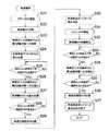
この即湯給湯システムにおける給湯動作は、次のようにして行われる。図1及び図2とともに図3及び図4を参照して、給湯を行うにはカラン30(出湯手段4)を開栓すればよい。カラン30を開栓する(ステップS1)と、給湯ライン6を通して水が流れ、所定流量以上の水の流れを流量検知手段34が検知する(ステップS2)と、熱源機8が作動し(ステップS3)、燃焼バーナ(図示せず)の燃焼によって温水が生成される。また、この流量検知手段34の検知信号に基づいて、弁制御手段44が三方切換弁12を第1切換状態に切り換え(ステップS4)、その第2ポート22と第1ポート18とが連通状態となる。流量検知手段34が検知する所定流量とは、例えば、熱源機8の燃焼下限流量に設定され、この場合、熱源機8が温水を生成すると、三方切換弁12が第1切換状態に切り換えられる。尚、給湯ライン6を通して燃焼下限流量より少ない水が流れるときには、熱源機8が作動することはなく、また三方切換弁12が第1切換状態に切り換わることはない。 The hot water supply operation in the instant hot water supply system is performed as follows. Referring to FIGS. 3 and 4 together with FIGS. 1 and 2, the hot water supply may be performed by opening the currant 30 (the hot water discharge means 4). When the
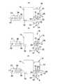
このように開栓すると、図3(a)(水、温水の流れを矢印で示す)に示すように、給湯ライン6の上流側部24の水(熱源機8からの温水が到達するまでの水)が三方切換弁12及びバイパスライン16の上流側部20を通して即湯保温ポット14の底部に送給され、かく送給された水が即湯保温ポット14内の温水(この温水は、後述する如くして即湯保温ポット14内に回収される)を押し上げ、かく押し上げられた温水がバイパスライン16の下流側部31及び給湯ライン6の下流側部28を通してカラン30に送給され、このカラン30から出湯する(ステップS5)。従って、カラン30を開栓すると、即湯保温ポット14からの温水がカラン30から出湯し、カラン30を開栓したとほぼ同時に温水を出湯させることができる。 When opened in this way, as shown in FIG. 3A (the flow of water and warm water is indicated by arrows), the water in the
そして、熱源機8にて生成された温水が三方切換弁12の近くまで流れて温度検知手段32まで到達し、温度検知手段32が温水を検知する(検知温度が例えば3.5℃になる)と、ステップS6からステップS7に進み、温度検知手段32からの検知信号に基づいて、弁制御手段44が三方切換弁12を第2切換状態に切り換える。 And the hot water produced | generated in the heat-
このように切り換えられると、図3(b)(水、温水の流れを矢印で示す)に示すように、給湯ライン6の上流側部24からの温水が三方切換弁12及び給湯ライン6の下流側部28を通してカラン20(出湯手段4)に流れ、これによって、即湯保温ポット14の温水から熱源機8の温水に切り換わり、カラン20から温水を継続して出湯することができる(ステップS8)。 When switched in this way, as shown in FIG. 3B (the flow of water and hot water is indicated by arrows), the hot water from the
その後、カラン30を閉栓する(ステップS9)と、給湯ライン6を流れる温水の流れが止まり、熱源機8が作動停止して温水の生成が終了する(ステップS10)。また、流量検知手段34が所定流量(例えば、燃焼下限流量)以上の水の流れを検知しなくなり(ステップS11)、この流量検知手段34の検知信号に基づいて、弁制御手段44が開閉弁38を開状態にし(ステップS12)、かく開状態に保持されると、タイマ手段46が計時を開始する(ステップS13)。 Thereafter, when the
このように開状態になると、図3(c)(水、温水の流れを矢印で示す)で示すように、即湯保温ポット14内の水が排水ライン36を通して排水される。このとき、絞り手段40により排水流量が制限され、その流量が熱源機8の燃焼下限流量よりも少なくなるように制限されるので、熱源機8が作動することなく、熱源機8からの水が給湯ライン6に送給され、これに伴い、給湯ライン6の上流側部24に残留する温水が、三方切換弁12、給湯ライン6の下流側部28及びバイパスライン16の下流側部31を通して即湯保温ポット14内に流れて回収される。 In this open state, as shown in FIG. 3C (the flow of water and warm water is indicated by arrows), the water in the hot water
このような温水の回収状態において、第2温度検知手段35が温水を検知する(その検知温度が、例えば35℃になる)と、この第2温度検知手段35の検知信号に基づいて、弁制御手段44が開閉弁38を閉状態にし、このようにして即湯保温ポット14への温水の回収が終了する(ステップS16)。 In such a warm water recovery state, when the second temperature detection means 35 detects warm water (the detection temperature becomes 35 ° C., for example), valve control is performed based on the detection signal of the second temperature detection means 35. The means 44 closes the on-off
第2温度検知手段35が温水を検知すると、即湯保温ポット14内が回収した温水で満たされたということであり、従って、これ以上の温水の回収は無駄となり、開閉弁38が閉状態に切り換えられ、残留する温水の回収が終了し、回収して貯えられた温水は、次の開栓時に利用される。 When the second temperature detection means 35 detects the hot water, it means that the hot water heat-insulating
また、このような温水の回収状態において、タイマ手段45が所定時間(即湯保温ポット14が回収温水で満たされるに要する時間であって、例えば、即湯保温ポット14の容量3Lで且つ排水の制限流量が1.5L/分である場合に2分程度に設定される)を計時すると、ステップS14からステップS17を経てステップS15に移り、弁制御手段44が開閉弁38を閉状態にし、この場合においても即湯保温ポット14への温水の回収が終了する(ステップS16)。 Further, in such a hot water recovery state, the timer means 45 is a predetermined time (the time required for the immediate hot
〔第2の実施形態〕
次に、図5及び図6を参照して、第2の実施形態の即湯給湯システムについて説明する。この第2の実施形態においては、切換弁手段として熱感式切換弁手段が用いられ、また流量制限開閉弁手段として熱感式流量開閉弁手段が用いられている。尚、以下の実施形態において、上述の第1の実施形態と実質上同一の部材には同一の参照番号を付し、その説明を省略する。[Second Embodiment]
Next, with reference to FIG.5 and FIG.6, the instant hot water supply system of 2nd Embodiment is demonstrated. In the second embodiment, a heat sensitive switching valve means is used as the switching valve means, and a heat sensitive flow rate switching valve means is used as the flow rate restriction opening / closing valve means. In the following embodiments, members substantially the same as those in the first embodiment described above are given the same reference numerals, and descriptions thereof are omitted.
図5において、この第2の実施形態では、流量制限開閉弁手段としての熱感式流量制限開閉弁手段37Aが用いられ、この熱感式流量制限開閉弁手段37Aが、熱感式開閉弁38A(所謂、サーモ式二方弁)及び絞り手段40から構成され、熱感式開閉弁38Aは加温されると開状態となる。そして、このことに関連して、熱感式開閉弁38Aを通して温水を流すための作動温水ライン52が設けられ、この作動温水ライン52の一端側が給湯ライン6の上流側部24に接続され、その他端側が給湯ライン6の下流側部28に接続されている。従って、給湯ライン6の上流側部24を流れる水(又は温水)の一部は、作動温水ライン52及び熱感式開閉弁38Aを通して給湯ライン6の下流側部28に流れ、作動温水ライン52を流れる温水により加温されると、熱感式開閉弁38Aが開状態に保持される。 In FIG. 5, in the second embodiment, a heat sensitive flow restricting on / off valve means 37A is used as a flow restricting on / off valve means, and the heat sensitive flow restricting on / off valve means 37A is used as a heat sensitive on / off
また、切換弁手段としての熱感式切換弁手段10Aは熱感式三方切換弁12A(所謂、サーモ式三方弁)から構成され、熱感式三方切換弁12Aは、加温されると第1切換状態(第2ポート22と第1ポート18とが連通状態となる切換状態)から第2切換状態(第2ポート22と第3ポート26とが連通状態となる切換状態)に切り換えられる。この第2の実施形態におけるその他の構成は、上述した第1の実施形態と実質上同一でよい。 Further, the heat-sensitive switching valve means 10A as the switching valve means is constituted by a heat-sensitive three-
第2の実施形態の即湯給湯システムにおける給湯動作は、次のようにして行われる。図5とともに図6を参照して、給湯を行うにはカラン30(出湯手段4)を開栓すればよい。カラン30を開栓する(ステップS21)と、給湯ライン6を通して水が流れ、その流量が燃焼下限流量以上であると、熱源機8が作動され(ステップS22)、燃焼バーナ(図示せず)の燃焼によって温水が生成される。熱源機8からの温水が熱感式三方切換弁12Aに到達するまでの間は、この熱感式三方切換弁12Aが冷えた状態にあって第1切換状態に保持されており(ステップS23)、その第2ポート22と第1ポート18とが連通状態となっている。従って、給湯ライン6の上流側部24の水が熱感式三方切換弁12A及びバイパスライン16の上流側部20を通して即湯保温ポット14の底部に送給され、かく送給された水により押し上げられた温水がバイパスライン16の下流側部31及び給湯ライン6の下流側部28を通してカラン30に送給され、カラン30を開栓したとほぼ同時に温水が出湯する(ステップS24)。 The hot water supply operation in the instant hot water supply system of the second embodiment is performed as follows. Referring to FIG. 6 together with FIG. 5, the hot water supply may be performed by opening the currant 30 (the hot water discharge means 4). When the
そして、熱源機8にて生成された温水が熱感式三方切換弁12Aまで流れて加温すると、ステップS25からステップS26に進み、熱感式三方切換弁12Aが第2切換状態に切り換えられ、給湯ライン6の上流側部24からの温水が熱感式三方切換弁12A及び給湯ライン6の下流側部28を通してカラン20(出湯手段4)に流れ、熱源機8からの温水がカラン20から出湯する(ステップS27)。 Then, when the hot water generated in the
このような出湯状態においては、熱源機8からの温水の一部が給湯ライン6の上流側部24から作動温水ライン52を通して給湯ライン6の下流側部28に流れ、かく流れる温水も熱感式三方切換弁12Aを通して流れる温水とともにカラン30から出湯する。このとき、作動温水ライン52を流れる温水によって熱感式開閉弁38Aが加温されると、ステップS28からステップS29に進み、この熱感式開閉弁38Aが開状態となる。 In such a hot water supply state, a part of the hot water from the
熱式開閉弁38Aが開状態になると、上述したように、即湯保温ポット14内の水が排水ライン36を通して排水され、このときの排水流量が絞り手段40により制限され、この排水に伴い、給湯ライン6の下流側部28を流れる温水の一部(又は作動温水ライン52を流れる温水の一部)がバイパスライン16の下流側部31を通して即湯保温ポット14内に流入し、この第2の実施形態においては、熱源機8からの温水を出湯している間に即湯保温ポット14への温水の回収が行われる(ステップS30)。 When the thermal on-off
その後、カラン30を閉栓する(ステップS31)と、給湯ライン6を流れる温水の流量が止まって熱源機8が作動停止し(ステップS32)、温水の生成が終了する。 Thereafter, when the
その後、放熱により熱感式三方切換弁12Aが冷めると、ステップS33からステップS34に進み、熱感式三方切換弁12Aが第1切換状態に切り換えられる。また、放熱により熱感式開閉弁38Aが冷めると、ステップS35からステップS36に進み、熱感式開閉弁38Aが閉状態となり、即湯保温ポット14からの排水が終了し、これにより、この即湯保温ポット14への温水の回収が終了し(ステップS37)、このようにして出湯動作が終了する。 Thereafter, when the heat sensitive three-
この第2の実施形態の即湯給湯システムでは、切換弁手段として熱感式切換弁手段10A(熱感式三方切換弁12A)を用い、また流量制限開閉弁手段として熱感式流量制限開閉弁手段37A(熱感式開閉弁38A)を用い、熱源機8にて生成される温水の熱を利用して制御しているので、電源などを必要とせずに設置することができ、既設の給湯システムにも容易に取り付けることができる。 In the instant hot water supply system according to the second embodiment, a heat sensitive switching valve means 10A (heat sensitive three-
以上、本発明に従う即湯給湯システムの実施形態について説明したが、本発明はこれら実施形態に限定されるものではなく、本発明の範囲を逸脱することなく種々の変更乃至修正が可能である。 As mentioned above, although the embodiment of the instant hot water supply system according to this invention was described, this invention is not limited to these embodiment, A various change thru | or correction | amendment is possible without deviating from the scope of the present invention.
例えば、上述した第1の実施形態では、切換弁手段として三方切換弁を用いているが、この三方切換弁に代えて、例えば二つの開閉弁(二方弁)の組合せを用いるようにしてもよい。かかる場合、二つの開閉弁を接続する接続ラインに給湯ライン6の上流側部24が接続され、一方の開閉弁に即湯保温ポット14からのバイパスライン16の上流側部20が接続され、他方の開閉弁に給湯ライン6の下流側部28が接続され、第1切換状態においては、一方の開閉弁が開状態に、他方の開閉弁が閉状態に保持され、また第2切換状態においては、一方の開閉弁が閉状態に、他方の開閉弁が開状態に保持される。 For example, in the first embodiment described above, a three-way switching valve is used as the switching valve means, but instead of this three-way switching valve, for example, a combination of two on-off valves (two-way valves) may be used. Good. In such a case, the
また、例えば、上述した実施形態では、温水供給源2を燃焼バーナを備えた熱源機8から構成しているが、このような熱源機8に限定されず、温水を貯湯する貯湯タンクなどから構成するようにしてもよい。 Further, for example, in the above-described embodiment, the hot
2 温水供給源
4 出湯手段
6 給湯ライン
8 熱源機
10(10A) 切換弁手段(熱感式切換弁手段)
12(12A) 三方切換弁(熱感式三方切換弁)
14 即湯保温ポット
16 バイパスライン
32 第1温度検知手段
34 流量検知手段
35 第2温度検知手段
36 排水ライン
37(37A) 流量制限開閉弁手段(熱感式流量制限開閉弁手段)
38(38A) 開閉弁(熱感式開閉弁)
40 絞り手段
52 作動温水ライン2 Hot
12 (12A) Three-way selector valve (heat-sensitive three-way selector valve)
14 Instant hot water
38 (38A) On-off valve (heat sensitive on-off valve)
40 Throttle means 52 Operating hot water line
Claims (6)
Translated fromJapanese前記出湯手段を開栓したときには、前記切換弁手段が第1切換状態に保持され、前記温水供給源からの温水が前記切換弁手段に送給されるまでの間にわたって、前記給湯ラインの上流側部の水が前記切換弁手段及び前記バイパス流路の上流側部を通して前記即湯保温ポット内に送給され、前記即湯保温ポット内の温水が前記バイパス流路の下流側部及び前記給湯ラインの下流側部を通して前記出湯手段に送給され、そして、前記温水供給源からの温水が前記切換弁手段まで送給されると、前記切換弁手段が第2切換状態に保持され、前記温水供給源からの温水が前記給湯ラインの前記上流側部、前記切換弁手段及び前記給湯ラインの前記下流側部を通して前記出湯手段に送給され、その後前記出湯手段を閉栓すると、前記給湯ラインの前記上流側部に残存する温水が前記切換弁手段及び前記バイパス流路の前記下流側部を通して前記即湯保温ポットに回収されることを特徴とする即湯給湯システム。A hot water supply source for supplying hot water, hot water supply means to which hot water from the hot water supply source is supplied via a hot water supply line, a bypass line provided by bypassing a part of the hot water supply line, and the bypass line An instantaneous hot water insulation pot disposed, and switching valve means disposed in the hot water supply line for switching the flow of water or hot water flowing through the hot water supply line,
When the hot water supply means is opened, the switching valve means is maintained in the first switching state, and the upstream side of the hot water supply line until hot water from the hot water supply source is supplied to the switching valve means. Water is fed into the hot water warming pot through the switching valve means and the upstream side of the bypass flow path, and the hot water in the quick hot water warming pot is fed to the downstream side of the bypass flow path and the hot water supply line. When the hot water from the hot water supply source is supplied to the switching valve means, the switching valve means is held in the second switching state, and the hot water supply is supplied. When hot water from a source is supplied to the hot water outlet through the upstream side of the hot water supply line, the switching valve means and the downstream side of the hot water supply line, and then the hot water outlet is closed, the upper side of the hot water supply line Immediate hot water heating system, wherein a hot water remaining in the side is recovered in the immediate water insulation pot through said downstream portion of said switching valve means and the bypass passage.
前記出湯手段を開栓したときには、前記熱感式切換弁手段が第1切換状態に保持され、前記温水供給源からの温水が前記熱感式切換弁手段に送給されるまでの間にわたって、前記給湯ラインの上流側部の水が前記熱感式切換弁手段及び前記バイパスラインの上流側部を通して前記即湯保温ポット内に送給され、前記即湯保温ポット内の温水が前記バイパスラインの下流側部及び前記給湯ラインの下流側部を通して前記出湯手段に送給され、そして、前記温水供給源からの温水が前記熱感式切換弁手段まで送給されると、前記熱感式切換弁手段が第2切換状態に保持され、前記温水供給源からの温水が前記給湯ラインの前記上流側部、前記切換弁手段及び前記給湯ラインの前記下流側部を通して前記出湯手段に送給され、温水供給手段からの温水出湯中に、前記給湯ラインの前記下流側部を流れる温水の一部が前記バイパスラインの前記下流側部を通して前記即湯保温ポットに回収されることを特徴とする即湯給湯システム。A hot water supply source for supplying hot water, hot water supply means to which hot water from the hot water supply source is supplied via a hot water supply line, a bypass line provided by bypassing a part of the hot water supply line, and the bypass line A hot water heat-insulating pot disposed, and a heat-sensitive switching valve means disposed in the hot water supply line for switching the flow of water or hot water flowing through the hot water supply line,
When the hot water discharge means is opened, the heat sensitive switching valve means is maintained in the first switching state, and the hot water from the hot water supply source is supplied to the heat sensitive switching valve means. Water on the upstream side of the hot water supply line is fed into the hot water warming pot through the heat sensitive switching valve means and the upstream side of the bypass line, and the hot water in the hot water warming pot is supplied to the bypass line. When the hot water from the hot water supply source is supplied to the hot water switching means through the downstream side and the downstream side of the hot water supply line, and when the hot water is supplied to the heat sensitive switching valve means, the heat sensitive switching valve Means is maintained in the second switching state, and hot water from the hot water supply source is supplied to the hot water supply means through the upstream side portion of the hot water supply line, the switching valve means, and the downstream side portion of the hot water supply line. Temperature from supply means During tapping, immediately hot water heating system, wherein a portion of the hot water flowing through the downstream portion of the hot water supply line is collected in the immediate water insulation pot through the downstream portion of the bypass line.
The instant hot water holding pot is provided with a drainage line, the drainage line is provided with a heat sensitive flow rate restricting on / off valve means, and the hot water warming pot is bypassed to pass through the heat sensitive flow rate restricting on / off valve means with hot water. When the hot water from the hot water source flows through the operating hot water line and the heat sensitive flow restriction valve is opened, the water in the hot water warming pot is supplied. Is drained through the drainage line and the heat sensitive flow rate restricting on / off valve, and the water drainage flow rate is restricted by the heat sensitive flow restricting on / off valve means, thereby flowing through the downstream side portion of the hot water supply line. 6. The hot water supply system according to claim 5, wherein a part of the hot water is collected in the hot water heat insulation pot through the downstream side portion of the bypass line.
Priority Applications (1)
| Application Number | Priority Date | Filing Date | Title |
|---|---|---|---|
| JP2012154506AJP6050042B2 (en) | 2012-07-10 | 2012-07-10 | Instant hot water supply system |
Applications Claiming Priority (1)
| Application Number | Priority Date | Filing Date | Title |
|---|---|---|---|
| JP2012154506AJP6050042B2 (en) | 2012-07-10 | 2012-07-10 | Instant hot water supply system |
Publications (2)
| Publication Number | Publication Date |
|---|---|
| JP2014016117Atrue JP2014016117A (en) | 2014-01-30 |
| JP6050042B2 JP6050042B2 (en) | 2016-12-21 |
Family
ID=50110963
Family Applications (1)
| Application Number | Title | Priority Date | Filing Date |
|---|---|---|---|
| JP2012154506AActiveJP6050042B2 (en) | 2012-07-10 | 2012-07-10 | Instant hot water supply system |
Country Status (1)
| Country | Link |
|---|---|
| JP (1) | JP6050042B2 (en) |
Citations (7)
| Publication number | Priority date | Publication date | Assignee | Title |
|---|---|---|---|---|
| JPS6435318U (en)* | 1987-08-25 | 1989-03-03 | ||
| JPH03129826U (en)* | 1990-04-09 | 1991-12-26 | ||
| JP2004125228A (en)* | 2002-09-30 | 2004-04-22 | Sekisui Chem Co Ltd | Water heater |
| JP2005325874A (en)* | 2004-05-12 | 2005-11-24 | Noritz Corp | Piping joint |
| JP2007139381A (en)* | 2005-11-22 | 2007-06-07 | Toto Ltd | Instantaneous hot water system |
| JP2010230205A (en)* | 2009-03-26 | 2010-10-14 | Panasonic Electric Works Co Ltd | Hot water system |
| JP2011075150A (en)* | 2009-09-29 | 2011-04-14 | Toto Ltd | Instantaneous water heater |
- 2012
- 2012-07-10JPJP2012154506Apatent/JP6050042B2/enactiveActive
Patent Citations (7)
| Publication number | Priority date | Publication date | Assignee | Title |
|---|---|---|---|---|
| JPS6435318U (en)* | 1987-08-25 | 1989-03-03 | ||
| JPH03129826U (en)* | 1990-04-09 | 1991-12-26 | ||
| JP2004125228A (en)* | 2002-09-30 | 2004-04-22 | Sekisui Chem Co Ltd | Water heater |
| JP2005325874A (en)* | 2004-05-12 | 2005-11-24 | Noritz Corp | Piping joint |
| JP2007139381A (en)* | 2005-11-22 | 2007-06-07 | Toto Ltd | Instantaneous hot water system |
| JP2010230205A (en)* | 2009-03-26 | 2010-10-14 | Panasonic Electric Works Co Ltd | Hot water system |
| JP2011075150A (en)* | 2009-09-29 | 2011-04-14 | Toto Ltd | Instantaneous water heater |
Also Published As
| Publication number | Publication date |
|---|---|
| JP6050042B2 (en) | 2016-12-21 |
Similar Documents
| Publication | Publication Date | Title |
|---|---|---|
| JP5334876B2 (en) | Solar water heating system and control method of solar water heating system | |
| JP2011149673A (en) | Solar heat hot water supply system | |
| JP2016138678A (en) | Hot water supply system | |
| JP6607375B2 (en) | Auxiliary heat source machine | |
| AU2010210013B2 (en) | Water heating apparatus | |
| JP2016180539A (en) | Storage water heater | |
| JP6050042B2 (en) | Instant hot water supply system | |
| JP5755532B2 (en) | Hot water storage system | |
| JP5821002B2 (en) | Hot water system | |
| JP2016038114A (en) | Hot water storage system | |
| JP6323234B2 (en) | Hot water storage hot water system | |
| JP4880312B2 (en) | Hot water storage hot water source | |
| JP5814643B2 (en) | Hot water storage system | |
| JP6771343B2 (en) | Heat supply system | |
| KR100852511B1 (en) | Apparatus of heating water in water purifier | |
| JP6197452B2 (en) | Hot water system | |
| JP6237988B2 (en) | Hot water storage system | |
| JP6214492B2 (en) | Heating system | |
| JP2014088971A (en) | Hot water supply system | |
| JP6015924B2 (en) | Hot water storage hot water system | |
| JP6143092B2 (en) | Hot water storage system | |
| JP5571611B2 (en) | Latent heat recovery type water heater | |
| KR200378537Y1 (en) | gas boiler protection burst from freezing and apparatus for supply warm-water | |
| JP6350173B2 (en) | Hot water system | |
| JP2002071210A (en) | Anti-freezing device for water heater and water heater with anti-freezing function using the same |
Legal Events
| Date | Code | Title | Description |
|---|---|---|---|
| A621 | Written request for application examination | Free format text:JAPANESE INTERMEDIATE CODE: A621 Effective date:20150619 | |
| A977 | Report on retrieval | Free format text:JAPANESE INTERMEDIATE CODE: A971007 Effective date:20160316 | |
| A131 | Notification of reasons for refusal | Free format text:JAPANESE INTERMEDIATE CODE: A131 Effective date:20160426 | |
| A521 | Written amendment | Free format text:JAPANESE INTERMEDIATE CODE: A523 Effective date:20160609 | |
| TRDD | Decision of grant or rejection written | ||
| A01 | Written decision to grant a patent or to grant a registration (utility model) | Free format text:JAPANESE INTERMEDIATE CODE: A01 Effective date:20161101 | |
| A61 | First payment of annual fees (during grant procedure) | Free format text:JAPANESE INTERMEDIATE CODE: A61 Effective date:20161124 | |
| R150 | Certificate of patent or registration of utility model | Ref document number:6050042 Country of ref document:JP Free format text:JAPANESE INTERMEDIATE CODE: R150 |