JP2014015083A - Fuel supply system for aircraft engine - Google Patents
Fuel supply system for aircraft engineDownload PDFInfo
- Publication number
- JP2014015083A JP2014015083AJP2012152587AJP2012152587AJP2014015083AJP 2014015083 AJP2014015083 AJP 2014015083AJP 2012152587 AJP2012152587 AJP 2012152587AJP 2012152587 AJP2012152587 AJP 2012152587AJP 2014015083 AJP2014015083 AJP 2014015083A
- Authority
- JP
- Japan
- Prior art keywords
- fuel
- engine
- pump
- fuel supply
- gear pump
- Prior art date
- Legal status (The legal status is an assumption and is not a legal conclusion. Google has not performed a legal analysis and makes no representation as to the accuracy of the status listed.)
- Granted
Links
- 239000000446fuelSubstances0.000titleclaimsabstractdescription140
- 239000002828fuel tankSubstances0.000claimsabstractdescription39
- 238000010586diagramMethods0.000description4
- 230000037396body weightEffects0.000description2
- 230000002787reinforcementEffects0.000description2
- 238000006073displacement reactionMethods0.000description1
- 238000002955isolationMethods0.000description1
Images

Landscapes
- Cooling, Air Intake And Gas Exhaust, And Fuel Tank Arrangements In Propulsion Units (AREA)
Abstract
Description
Translated fromJapanese本発明は、航空機のエンジンに対して燃料を供給する装置に関する。 The present invention relates to an apparatus for supplying fuel to an aircraft engine.
航空機の推進装置として使用されるガスタービンエンジンにおいては、エンジンの燃料ポンプが機体の燃料タンクから吸引した燃料を昇圧し、さらに、燃料コントロール部が必要な流量、圧力に調整して、エンジンに燃料を供給する。エンジンの燃料ポンプは一般に、燃料コントロール部に高圧の燃料を供給するギアポンプと、ギアポンプ入口の燃料圧力を昇圧する低圧ポンプ(遠心ポンプ)によって構成される。現在の航空機では一般に、エンジンの動力が補機駆動用ギアボックスを介して燃料ポンプに伝達され、この動力によって燃料ポンプが回転される。したがって、燃料ポンプはエンジンの補機としてエンジン外周上に取り付けられる。これらのポンプ類や燃料コントロール部と配管等で、エンジン側の燃料システムが構成されている。 In a gas turbine engine used as an aircraft propulsion device, the fuel pump of the engine pressurizes the fuel drawn from the fuel tank of the fuselage, and the fuel control unit adjusts to the required flow rate and pressure, and the fuel is supplied to the engine. Supply. An engine fuel pump is generally composed of a gear pump that supplies high-pressure fuel to a fuel control unit and a low-pressure pump (centrifugal pump) that increases the fuel pressure at the gear pump inlet. In a current aircraft, generally, engine power is transmitted to a fuel pump through an accessory drive gearbox, and the fuel pump is rotated by this power. Accordingly, the fuel pump is mounted on the outer periphery of the engine as an auxiliary machine of the engine. The fuel system on the engine side is constituted by these pumps, the fuel control section, and the piping.
一方、燃料タンクは多くの場合、航空機の翼に設けられる。翼からエンジン側の燃料ポンプに必要な圧力で燃料を供給するには、低圧ポンプ(遠心ポンプ)の吸い込み性能の限界から来る供給圧不足を補うための燃料システムが機体側にも必要となる。機体側の燃料システムは、翼の燃料タンクの他に、一般的に胴体に搭載されるブーストポンプとその駆動源である電動モータ、さらに、燃料タンクとブーストポンプを接続する配管等で構成される。 On the other hand, fuel tanks are often provided on aircraft wings. In order to supply fuel at a pressure required from the blade to the engine-side fuel pump, a fuel system is also required on the fuselage side to compensate for the supply pressure shortage resulting from the limit of the suction performance of the low-pressure pump (centrifugal pump). In addition to the wing fuel tank, the fuselage-side fuel system is generally composed of a boost pump mounted on the fuselage, an electric motor as its drive source, and a pipe connecting the fuel tank and the boost pump. .
ところで、エンジン側の燃料システムでは、燃料ポンプが補機駆動用ギアボックスを介してエンジン軸から入力される動力を駆動源としていることから、エンジンの回転数に依存して燃料ポンプの回転数が変化する。ギアポンプのような定容積型ポンプの場合は、ポンプが吐出する流量がエンジンの回転数によって決まるため、エンジンの燃焼器が必要とする燃料に対して余剰となる燃料が発生する。そこで、専用の電動モータにより燃料ポンプとしてのギアポンプを回転させる提案も行われている(例えば、特許文献1)。ギアポンプを電動モータにより回転させれば、エンジンの回転数に依存せずにギアポンプの回転数をコントロールすることができる。 By the way, in the fuel system on the engine side, since the fuel pump uses the power input from the engine shaft via the accessory drive gearbox as a drive source, the speed of the fuel pump depends on the engine speed. Change. In the case of a constant displacement pump such as a gear pump, since the flow rate discharged from the pump is determined by the engine speed, surplus fuel is generated relative to the fuel required by the combustor of the engine. Then, the proposal which rotates the gear pump as a fuel pump with a dedicated electric motor is also performed (for example, patent document 1). If the gear pump is rotated by an electric motor, the rotation speed of the gear pump can be controlled without depending on the rotation speed of the engine.
しかし、上述したように燃料ポンプとしてのギアポンプを専用の電動モータで回転させる場合であっても、ギアポンプ(燃料ポンプ)がエンジン側に設けられることに変わりはない。このため、低圧ポンプ(遠心ポンプ)の吸い込み性能の限界から来る供給圧不足を補う必要性は相変わらず残り、機体(例えば胴体)側にはやはりブーストポンプを設けなければならない。 However, as described above, even when a gear pump as a fuel pump is rotated by a dedicated electric motor, the gear pump (fuel pump) is still provided on the engine side. For this reason, the necessity to compensate for the supply pressure shortage resulting from the limit of the suction performance of the low-pressure pump (centrifugal pump) still remains, and a boost pump must also be provided on the fuselage (for example, the fuselage) side.
このような背景から、エンジン側のギアポンプ(燃料ポンプ)を電動モータにより回転させる場合でも、機体側のブーストポンプを削減することは困難である。このように、エンジン側と機体側とにそれぞれポンプ(エンジン側の燃料ポンプ、機体側のブーストポンプ)をそれぞれ設けると、航空機の重量が増加して燃費等に影響を与え、また、燃料供給系の構造が複雑化してしまう。 Against this background, even when the engine-side gear pump (fuel pump) is rotated by an electric motor, it is difficult to reduce the fuselage-side boost pump. As described above, if pumps (engine-side fuel pump, fuselage-side boost pump) are provided on the engine side and the fuselage side, respectively, the weight of the aircraft increases to affect fuel consumption, and the fuel supply system The structure becomes complicated.
本発明の目的は、全体での装置規模を縮減できる航空機エンジンの燃料供給装置を提供することにある。 An object of the present invention is to provide an aircraft engine fuel supply apparatus that can reduce the overall apparatus scale.
本発明は、上述したエンジン側の燃料システムにおけるギアポンプの駆動源を電動モータとする提案に着目してなされたもので、上記目的を達成するため、請求項1に記載した本発明の航空機エンジンの燃料供給装置は、
航空機の機体側でブーストした燃料タンクの燃料を、前記機体に取り付けたエンジンナセル内のエンジンに、遠心ポンプ及びギアポンプで昇圧して供給する航空機エンジンの燃料供給装置において、
前記遠心ポンプ及び前記ギアポンプが前記機体側に配置されて、前記燃料タンクの燃料のブーストが前記遠心ポンプによって行われると共に、前記遠心ポンプ及び前記ギアポンプが前記機体側の電動モータにより回転駆動される、
ことを特徴とする。The present invention has been made paying attention to the proposal that the drive source of the gear pump in the engine-side fuel system described above is an electric motor. In order to achieve the above object, the aircraft engine of the present invention according to
In a fuel supply device for an aircraft engine, the fuel in the fuel tank boosted on the aircraft body side is boosted and supplied to the engine in the engine nacelle attached to the aircraft by a centrifugal pump and a gear pump.
The centrifugal pump and the gear pump are arranged on the airframe side, the fuel of the fuel tank is boosted by the centrifugal pump, and the centrifugal pump and the gear pump are rotationally driven by an electric motor on the airframe side.
It is characterized by that.
請求項1に記載した本発明の航空機エンジンの燃料供給装置によれば、ギアポンプと遠心ポンプを電動モータにより回転駆動させることとしたので、エンジン側の補機駆動用ギアボックスに搭載する必要がなく、機体側ユニットとして胴体に配置することができる。これにより、遠心ポンプとギアポンプをエンジンによる振動の影響を多く受けるエンジン外周上でなく、振動の影響が少ない胴体に配置することができる。このため、燃料供給装置としての耐久性を高めることができる。加えて、耐震補強部材の削減により機体重量の軽量化も図ることができる。 According to the fuel supply device for an aircraft engine of the present invention described in
また、エンジンによりギアポンプを回転駆動させるよりも、それらの回転数をエンジンの回転数に依存せずにコントロールすることができ、さらに、燃料供給系の全体構成を簡略化することができる。即ち、従来のように、機体側にブースト系の昇圧手段を、エンジン側に低圧系(遠心ポンプ)及び高圧系(ギアポンプ)の昇圧手段を、それぞれ配置する必要をなくし、昇圧手段の構成を簡略化して装置規模を縮減し、重量の低減と信頼性の向上とを図ることができる。 Further, the rotational speed of the gear pump can be controlled without depending on the rotational speed of the engine, rather than the gear pump being driven to rotate by the engine, and the overall configuration of the fuel supply system can be simplified. In other words, unlike the prior art, it is not necessary to arrange boosting boosting means on the airframe side and low pressure system (centrifugal pump) and high pressure system (gear pump) boosting means on the engine side, and the configuration of the boosting means is simplified. To reduce the scale of the apparatus, thereby reducing the weight and improving the reliability.
また、請求項2に記載した本発明の航空機エンジンの燃料供給装置は、請求項1に記載した本発明の航空機エンジンの燃料供給装置において、前記燃料タンクと、前記遠心ポンプ、前記ギアポンプ及び前記電動モータの機体側ユニットとが、複数の前記エンジンに対応して複数組設けられており、各組の前記機体側ユニットに、前記遠心ポンプによるブースト後の燃料の供給先を他の前記機体側ユニットの前記ギアポンプとの間で切り替え、又は、前記ギアポンプによる昇圧後の燃料の供給先を他の前記機体側ユニットに対応する前記エンジンとの間で切り替える供給先切替手段がそれぞれ設けられていることを特徴とする。 An aircraft engine fuel supply apparatus according to a second aspect of the present invention is the aircraft engine fuel supply apparatus according to the first aspect of the present invention, wherein the fuel tank, the centrifugal pump, the gear pump, and the electric motor are provided. A plurality of airframe side units of the motor are provided corresponding to the plurality of engines, and the fuel supply destination after boosting by the centrifugal pump is supplied to each airframe side unit of each set other airframe side units. Supply destination switching means for switching between the engine and the engine corresponding to the other airframe unit is provided. Features.
請求項2に記載した本発明の航空機エンジンの燃料供給装置によれば、請求項1に記載した本発明の航空機エンジンの燃料供給装置において、複数存在する機体側ユニットの1つが故障した場合や、複数存在するエンジンの1つが故障した場合に、特定の燃料タンクの燃料が集中的に消費されるのを回避する燃料供給経路を、過度に構成を煩雑化させることなく確保することができる。 According to the aircraft engine fuel supply device of the present invention described in claim 2, in the aircraft engine fuel supply device of the present invention described in
さらに、請求項3に記載した本発明の航空機エンジンの燃料供給装置は、請求項2に記載した本発明の航空機エンジンの燃料供給装置において、予備の前記機体側ユニットがさらに少なくとも1組設けられており、該予備の機体側ユニットが、燃料の供給元を前記各燃料タンクのいずれかに選択的に切り替える供給元切替手段をさらに有していて、前記予備の機体側ユニットの前記供給先切替手段が、前記ギアポンプによる昇圧後の燃料の供給先を、前記各組の前記機体側ユニットにそれぞれ対応する各エンジンの間で切り替えることを特徴とする。 Further, an aircraft engine fuel supply apparatus according to a third aspect of the present invention is the aircraft engine fuel supply apparatus according to the second aspect of the present invention, further comprising at least one spare airframe unit. The spare airframe side unit further includes a supply source switching means for selectively switching a fuel supply source to one of the fuel tanks, and the supply destination switching means of the spare airframe side unit. However, the fuel supply destination after the pressure increase by the gear pump is switched between the engines corresponding to the airframe side units of the sets.
請求項3に記載した本発明の航空機エンジンの燃料供給装置によれば、請求項2に記載した本発明の航空機エンジンの燃料供給装置において、複数存在する機体側ユニットの1つが故障した場合に、故障した機体側ユニットが燃料供給を受けていた燃料タンクの燃料を予備の機体側ユニットで昇圧して、故障した機体側ユニットに代わって対応するエンジンに引き続き供給する経路を、過度に構成を煩雑化させることなく確保することができる。 According to the aircraft engine fuel supply apparatus of the present invention described in claim 3, in the aircraft engine fuel supply apparatus of the present invention described in claim 2, when one of a plurality of airframe-side units fails, The fuel tank that had been damaged by the failed aircraft unit boosts the fuel in the fuel tank with the spare aircraft unit and continues to supply the corresponding engine on behalf of the failed aircraft unit. It can be secured without making it.
本発明によれば、航空機エンジンの燃料供給装置の全体での装置規模を縮減することができる。 ADVANTAGE OF THE INVENTION According to this invention, the apparatus scale in the whole fuel supply apparatus of an aircraft engine can be reduced.
以下、本発明の実施形態について図面を参照しながら説明する。 Hereinafter, embodiments of the present invention will be described with reference to the drawings.
〔第1実施形態〕
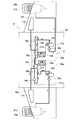
図1の説明図に示す第1実施形態の燃料供給装置1(航空機エンジンの燃料供給装置に相当)は、航空機Aの左右の翼10a,10bにパイロン(図示せず)を介して連結したエンジンナセル20a,20b内のガスタービンエンジン(以下、「エンジン」と略記する。)21a,21bに燃料を供給するものである。そして、燃料供給装置1は、左右の各エンジン21a,21bに対応する燃料タンク11a,11bと左右の機体側ユニット30a,30bを有している。[First Embodiment]
A fuel supply device 1 (corresponding to a fuel supply device for an aircraft engine) of the first embodiment shown in the explanatory diagram of FIG. 1 is an engine connected to left and
左右の燃料タンク11a,11bは、左右の各翼10a,10bにそれぞれ設けられている。左右の各機体側ユニット30a,30bは、翼10a,10bの付け根に近い胴体30に設けられた低圧ポンプ31a,31b、ギアポンプ32a,32b、及び、電動モータ33a,33bを有している。 The left and
低圧ポンプ31a,31b(請求項中の遠心ポンプに相当)及びギアポンプ32a,32bは、電動モータ33a,33bによってそれぞれ回転駆動される。低圧ポンプ31a,31bは、燃料タンク11a,11bの燃料をブーストし、ギアポンプ32a,32bは、ブーストされた燃料を昇圧して対応する左右のエンジン21a,21bにそれぞれ供給する。 The low-
低圧ポンプ31aには、ギアポンプ32aへの配管34aと共にギアポンプ32bへの配管35aが接続されており、低圧ポンプ31bにも、ギアポンプ32bへの配管34bと共にギアポンプ32aへの配管35bが接続されている。ギアポンプ32aへの配管34a及び配管35bと、ギアポンプ32bへの配管34b及び配管35aは、それぞれ合流している。配管35a,35bにはクロスフィード弁(開閉弁)36b,36aが介設されている。 A
ギアポンプ32a及びエンジン21aを接続する配管37aと、ギアポンプ32b及びエンジン21bを接続する配管37bには、遮断弁38a,38bがそれぞれ介設されている。
以上のように構成された第1実施形態の燃料供給装置1では、通常時は、クロスフィード弁36a,36bが閉弁され、遮断弁38a,38bが開弁される。そして、燃料タンク11aの燃料が低圧ポンプ31aでブーストされ、さらに、配管34aを介してギアポンプ32aに供給された燃料が昇圧されて、左エンジン21aに供給される。 In the
同様に、燃料タンク11bの燃料が低圧ポンプ31bでブーストされ、さらに、配管34bを介してギアポンプ32bに供給された燃料が昇圧されて、右エンジン21bに供給される。 Similarly, the fuel in the
なお、右エンジン21bが故障し左エンジン21aのみが稼働される場合は、左翼10aの燃料タンク11aの燃料だけが消費されて重量バランスが崩れないように、クロスフィード弁36aが開弁されて、右翼10bの燃料タンク11bの燃料も低圧ポンプ31bによるブースト後に配管35aを介してギアポンプ32aに供給される。 If the
同様に、左エンジン21aが故障し右エンジン21bのみが稼働される場合は、右翼10bの燃料タンク11bの燃料だけが消費されて重量バランスが崩れないように、クロスフィード弁36bが開弁されて、左翼10aの燃料タンク11aの燃料も低圧ポンプ31aによるブースト後に配管35aを介してギアポンプ32bに供給される。 Similarly, when the
上述した第1実施形態の燃料供給装置1では、配管35a,34b及びクロスフィード弁(開閉弁)36a,36bが、請求項中の、低圧ポンプによるブースト後の燃料の供給先を他の機体側ユニットのギアポンプとの間で切り替える供給先切替手段を構成している。 In the
〔第2実施形態〕
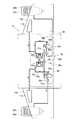
図2の説明図に示す第2実施形態の燃料供給装置1a(航空機エンジンの燃料供給装置に相当)は、第1実施形態の燃料供給装置1の配管35a,35b及びクロスフィード弁(開閉弁)36a,36bを省略している。[Second Embodiment]
A
その代わりに、第2実施形態の燃料供給装置1aは、ギアポンプ32a,32bと遮断弁38a,38bとの間で 配管37a,37bどうしを配管39で接続し、また、遮断弁38a,38bとエンジン21a,21bとの間で配管37a,37bどうしを配管40で接続している。さらに、配管39,40を配管41で接続し、かつ、配管39,41の接続部分にクロスフィード弁(三方弁)42を設けている。 Instead, in the
以上のように構成された第2実施形態の燃料供給装置1aでは、通常時は、クロスフィード弁42により配管39,40,41が相互に遮断され、遮断弁38a,38bが開弁される。そして、燃料タンク11aの燃料が低圧ポンプ31aでブーストされ、さらに、配管34aを介してギアポンプ32aに供給された燃料が昇圧されて、左エンジン21aに供給される。 In the
同様に、燃料タンク11bの燃料が低圧ポンプ31bでブーストされ、さらに、配管34bを介してギアポンプ32bに供給された燃料が昇圧されて、右エンジン21bに供給される。 Similarly, the fuel in the
なお、右エンジン21bが故障し左エンジン21aのみが稼働される場合は、左翼10aの燃料タンク11aの燃料だけが消費されて重量バランスが崩れないように、周期的に、クロスフィード弁42により配管39が開弁されると共に、遮断弁38bが閉弁されて、右翼10bの燃料タンク11bの燃料が低圧ポンプ31b、ギアポンプ32b、配管39及び遮断弁38a(開弁)を介して左エンジン21aに供給される。 If the
同様に、左エンジン21aが故障し右エンジン21bのみが稼働される場合は、右翼10bの燃料タンク11bの燃料だけが消費されて重量バランスが崩れないように、周期的に、クロスフィード弁42により配管39が開弁されると共に、遮断弁38aが閉弁されて、左翼10aの燃料タンク11aの燃料が低圧ポンプ31a、ギアポンプ32a、配管39及び遮断弁38b(開弁)を介して右エンジン21bに供給される。 Similarly, when the
また、左の機体側ユニット30aの低圧ポンプ31aやギアポンプ32aが故障した場合は、クロスフィード弁42により配管39の配管37b側と配管41が連通されて、右の機体側ユニット30bでブースト及び昇圧された燃料が、ギアポンプ32bから、右エンジン21bと並行して、配管39及び遮断弁38a(開弁)を介して左エンジン21aにも供給される。 Further, when the
同様に、右の機体側ユニット30bの低圧ポンプ31bやギアポンプ32aが故障した場合は、クロスフィード弁42により配管39の配管37a側と配管41が連通されて、左の機体側ユニット30aでブースト及び昇圧された燃料が、ギアポンプ32aから、左エンジン21aと並行して、配管39及び遮断弁38b(開弁)を介して右エンジン21bにも供給される。 Similarly, when the
上述した第2実施形態の燃料供給装置1aでは、遮断弁38a,38b、配管39,40,41及びクロスフィード弁(開閉弁)42が、請求項中の、ギアポンプによる昇圧後の燃料の供給先を他の機体側ユニットに対応するエンジンとの間で切り替える供給先切替手段を構成している。 In the
〔第3実施形態〕
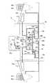
図3の説明図に示す第3実施形態の燃料供給装置1b(航空機エンジンの燃料供給装置に相当)は、第2実施形態の燃料供給装置1aに対して、予備の機体側ユニット30cを追加している。[Third Embodiment]
A
予備の機体側ユニット30cは、胴体30に設けられた低圧ポンプ31c(請求項中の遠心ポンプに相当)、ギアポンプ32c、及び、電動モータ33cを有している。ギアポンプ32cは、クロスフィード弁(三方弁)43により、燃料の供給元を左右の燃料タンク11a,11bのどちらかに切り替えることができる。また、ギアポンプ32cで昇圧した燃料は、クロスフィード弁(三方弁)44により、配管37a,37bにおける配管39の接続点と遮断弁38a,38bとの間のどちらかに切り替えることができる。 The spare
以上のように構成された第3実施形態の燃料供給装置1bでは、通常時や左右のどちらか一方のエンジン21a,21bの故障時は、第2実施形態の燃料供給装置1aと同様にして燃料供給が行われ、予備の機体側ユニット30cは使用されない。 In the
また、左の機体側ユニット30aの低圧ポンプ31aやギアポンプ32aが故障した場合は、クロスフィード弁43により左翼10aの燃料タンク11aが予備の機体側ユニット30cの低圧ポンプ31cに接続されると共に、クロスフィード弁44によりギアポンプ32cが配管37aに接続される。そして、予備の機体側ユニット30cでブースト及び昇圧された燃料が、ギアポンプ32cからクロスフィード弁44、配管37a及び遮断弁38a(開弁)を介して左エンジン21aに供給される。 When the
同様に、右の機体側ユニット30bの低圧ポンプ31bやギアポンプ32aが故障した場合は、クロスフィード弁43により右翼10bの燃料タンク11bが予備の機体側ユニット30cの低圧ポンプ31cに接続されると共に、クロスフィード弁44によりギアポンプ32cが配管37bに接続される。そして、予備の機体側ユニット30cでブースト及び昇圧された燃料が、ギアポンプ32cからクロスフィード弁44、配管37b及び遮断弁38b(開弁)を介して右エンジン21bに供給される。 Similarly, when the
以上に説明した第1乃至第3実施形態の燃料供給装置1,1a,1bでは、ギアポンプ32a,32bを、低圧ポンプ31a,31bと共通の電動モータ33a,33bにより回転駆動させることとしたので、機体側ユニット30a,30bとして胴体30に配置することができる。 In the
これにより、低圧ポンプ31a,31bとギアポンプ32a,32bを、エンジン21a,21bによる振動の影響を多く受けるエンジン外周上でなく振動の影響が少ない胴体30に配置することができる。このため、燃料供給装置1,1a,1bとしての耐久性を高めることができる。加えて、耐震補強部材の削減により機体重量の軽量化も図ることができる。 As a result, the low-
また、エンジン21a,21bによりギアポンプ32a,32bを回転駆動させるよりも、それらの回転数をエンジン21a,21bの回転数に依存せずにコントロールすることができる。 Further, the rotational speeds of the gear pumps 32a and 32b can be controlled independently of the rotational speeds of the
さらに、エンジン21a,21bによりギアポンプ32a,32bを回転駆動させるよりも、燃料供給系の全体構成を簡略化することができる。 Furthermore, the overall configuration of the fuel supply system can be simplified as compared with the case where the gear pumps 32a and 32b are rotationally driven by the
即ち、図4の説明図に示す一般的な燃料供給装置1cのように、低圧ポンプ51a,51bとギアポンプ52a,52bをエンジン外周上に設けて、エンジン21a,21bにより補機駆動用ギアボックス53a,53bを介してギアポンプ52a,52bを回転駆動させる場合は、胴体30側に別途、ブーストポンプ61a,61bとその回転駆動源としての電動モータ62a,62bを設ける必要がある。 That is, as in the general
また、ギアポンプ52a,52bの回転数がエンジン21a,21bの回転数に依存することから、余剰の燃料をギアポンプ52a,52bの手前に還流させる燃料コントロール部(計量部)54a,54bをエンジン外周上に設ける必要がある。さらに、遮断弁55a,55bもエンジン外周上に設ける必要がある。 Further, since the rotational speeds of the gear pumps 52a and 52b depend on the rotational speeds of the
したがって、翼10a,10bや胴体30側とエンジン外周上との双方に、燃料を昇圧供給する燃料ユニットをそれぞれ設けなければならず、燃料供給装置の全体として大型化、重量化してしまう。また、エンジン外周上の低圧ポンプ51a,51bとは別に、エンジン側への供給圧を確保するため、胴体30側にブーストポンプ61a,61bが必要となり、ポンプ系の重複も発生してしまう。 Therefore, it is necessary to provide fuel units for boosting the fuel on both the
このような問題を、第1乃至第3実施形態の燃料供給装置1,1a,1bによれば、いずれも解消することができる。 Such a problem can be solved according to the
また、第1乃至第3実施形態の燃料供給装置1,1a,1bによれば、左右のエンジン21a,21bのどちらかが故障した場合に、左右のどちらか一方の燃料タンク11a,11bの燃料が集中的に消費されるのを回避する燃料供給経路を、過度に構成を煩雑化させることなく確保することができる。 Further, according to the
さらに、第2及び第3実施形態の燃料供給装置1a,1bによれば、左右の機体側ユニット30a,30bのどちらかが故障した場合にも、左右のどちらか一方の燃料タンク11a,11bの燃料が集中的に消費されるのを回避する燃料供給経路を、過度に構成を煩雑化させることなく確保することができる。 Furthermore, according to the
また、第3実施形態の燃料供給装置1bによれば、左右の機体側ユニット30a,30bのどちらかが故障した場合に、故障した機体側ユニット30a,30bが燃料供給を受けていた燃料タンク11a,11bの燃料を予備の機体側ユニット30cで昇圧して、故障した機体側ユニット30a,30bに代わって対応するエンジン21a,21bに引き続き供給する経路を、過度に構成を煩雑化させることなく確保することができる。なお、追加する予備の機体側ユニット30cは1組でなく複数組であってもよい。 Further, according to the
上述した第1乃至第3実施形態では、双発機を例に取り、左右の翼10a,10bのエンジン21a,21bに対する燃料供給装置1,1a,1bについて説明したが、本発明は、尾翼等の翼以外の部分にエンジンを配置した航空機にも適用可能である。その場合、機体側ユニットの低圧ポンプ、ギアポンプ、電動モータは、尾翼に近い胴体部分に配置してもよい。即ち、機体側ユニットは、燃料供給対象のエンジンの取付位置に応じてそれに近い胴体部分や翼の部分に配置することができる。 In the first to third embodiments described above, the twin-engine is taken as an example, and the
また、本発明は、軍用機であるか民間機であるかや、旅客機であるか貨物機であるかに関係なく、推進装置としてのエンジンに燃料を供給する航空機に広く適用可能である。 The present invention can be widely applied to an aircraft that supplies fuel to an engine as a propulsion device regardless of whether it is a military aircraft or a civilian aircraft, a passenger aircraft, or a cargo aircraft.
1,1a,1b,1c 燃料供給装置
10a 左翼
10b 右翼
11a,11b 燃料タンク
20a,20b エンジンナセル
21a 左エンジン
21b 右エンジン
30 胴体
30a,30b,30c 機体側ユニット
31a,31b,31c,51a,51b 低圧ポンプ(遠心ポンプ)
32a,32b,32c,52a,52b ギアポンプ
33a,33b,33c,62a,62b 電動モータ
34a,34b,35a,35b,37a,37b,39,40,41 配管
36a,36b,42,43,44 クロスフィード弁
38a,38b,55a,55b 遮断弁
53a,53b 補機駆動用ギアボックス
54a,54b 燃料コントロール部(計量部)
61a,61b ブーストポンプ
A 航空機1, 1a, 1b, 1c
32a, 32b, 32c, 52a,
61a, 61b Boost pump A Aircraft
Claims (3)
Translated fromJapanese前記遠心ポンプ及び前記ギアポンプが前記機体側に配置されて、前記燃料タンクの燃料のブーストが前記遠心ポンプによって行われると共に、前記遠心ポンプ及び前記ギアポンプが前記機体側の電動モータにより回転駆動される、
ことを特徴とする航空機エンジンの燃料供給装置。In a fuel supply device for an aircraft engine, the fuel in the fuel tank boosted on the aircraft body side is boosted and supplied to the engine in the engine nacelle attached to the aircraft by a centrifugal pump and a gear pump.
The centrifugal pump and the gear pump are arranged on the airframe side, the fuel of the fuel tank is boosted by the centrifugal pump, and the centrifugal pump and the gear pump are rotationally driven by an electric motor on the airframe side.
An aircraft engine fuel supply apparatus characterized by the above.
Priority Applications (1)
| Application Number | Priority Date | Filing Date | Title |
|---|---|---|---|
| JP2012152587AJP6044140B2 (en) | 2012-07-06 | 2012-07-06 | Aircraft engine fuel supply system |
Applications Claiming Priority (1)
| Application Number | Priority Date | Filing Date | Title |
|---|---|---|---|
| JP2012152587AJP6044140B2 (en) | 2012-07-06 | 2012-07-06 | Aircraft engine fuel supply system |
Publications (2)
| Publication Number | Publication Date |
|---|---|
| JP2014015083Atrue JP2014015083A (en) | 2014-01-30 |
| JP6044140B2 JP6044140B2 (en) | 2016-12-14 |
Family
ID=50110186
Family Applications (1)
| Application Number | Title | Priority Date | Filing Date |
|---|---|---|---|
| JP2012152587AActiveJP6044140B2 (en) | 2012-07-06 | 2012-07-06 | Aircraft engine fuel supply system |
Country Status (1)
| Country | Link |
|---|---|
| JP (1) | JP6044140B2 (en) |
Cited By (2)
| Publication number | Priority date | Publication date | Assignee | Title |
|---|---|---|---|---|
| WO2021039902A1 (en)* | 2019-08-30 | 2021-03-04 | 川崎重工業株式会社 | Gas turbine engine |
| CN113148195A (en)* | 2021-04-26 | 2021-07-23 | 浙江万丰飞机制造有限公司 | General aircraft fuel tank of aviation kerosene fixed wing |
Citations (9)
| Publication number | Priority date | Publication date | Assignee | Title |
|---|---|---|---|---|
| US3627239A (en)* | 1970-04-20 | 1971-12-14 | Gen Electric | Aircraft engine fuel system |
| US4075833A (en)* | 1976-01-02 | 1978-02-28 | General Electric Company | Variable area inlet for a gas turbine engine |
| US4441156A (en)* | 1981-01-21 | 1984-04-03 | Teledyne Industries, Inc. | Integrated fuel management system |
| JPS60135630A (en)* | 1983-12-02 | 1985-07-19 | ユナイテッド・テクノロジーズ・コーポレイション | Fuel pump system |
| JP2003226295A (en)* | 2002-02-04 | 2003-08-12 | Honda Motor Co Ltd | Aircraft fuel supply |
| US20070130911A1 (en)* | 2005-12-13 | 2007-06-14 | Hamilton Sundstrand Corporation | Smart fuel control system |
| JP2009067387A (en)* | 2008-11-27 | 2009-04-02 | Sumitomo Precision Prod Co Ltd | Leg raising/lowering system and steering system for moving body |
| US20100044515A1 (en)* | 2008-08-25 | 2010-02-25 | Rubens Domecildes Neto | Continual transference of fuel between fuel tanks at a rate commensurate with fuel burn during cruise flight operation to maintain the aircraft center of gravity within a pre-selected aft center of gravity envelope |
| JP2010506795A (en)* | 2006-10-20 | 2010-03-04 | ザ・ボーイング・カンパニー | Fuel balancing system |
- 2012
- 2012-07-06JPJP2012152587Apatent/JP6044140B2/enactiveActive
Patent Citations (9)
| Publication number | Priority date | Publication date | Assignee | Title |
|---|---|---|---|---|
| US3627239A (en)* | 1970-04-20 | 1971-12-14 | Gen Electric | Aircraft engine fuel system |
| US4075833A (en)* | 1976-01-02 | 1978-02-28 | General Electric Company | Variable area inlet for a gas turbine engine |
| US4441156A (en)* | 1981-01-21 | 1984-04-03 | Teledyne Industries, Inc. | Integrated fuel management system |
| JPS60135630A (en)* | 1983-12-02 | 1985-07-19 | ユナイテッド・テクノロジーズ・コーポレイション | Fuel pump system |
| JP2003226295A (en)* | 2002-02-04 | 2003-08-12 | Honda Motor Co Ltd | Aircraft fuel supply |
| US20070130911A1 (en)* | 2005-12-13 | 2007-06-14 | Hamilton Sundstrand Corporation | Smart fuel control system |
| JP2010506795A (en)* | 2006-10-20 | 2010-03-04 | ザ・ボーイング・カンパニー | Fuel balancing system |
| US20100044515A1 (en)* | 2008-08-25 | 2010-02-25 | Rubens Domecildes Neto | Continual transference of fuel between fuel tanks at a rate commensurate with fuel burn during cruise flight operation to maintain the aircraft center of gravity within a pre-selected aft center of gravity envelope |
| JP2009067387A (en)* | 2008-11-27 | 2009-04-02 | Sumitomo Precision Prod Co Ltd | Leg raising/lowering system and steering system for moving body |
Cited By (5)
| Publication number | Priority date | Publication date | Assignee | Title |
|---|---|---|---|---|
| WO2021039902A1 (en)* | 2019-08-30 | 2021-03-04 | 川崎重工業株式会社 | Gas turbine engine |
| JPWO2021039902A1 (en)* | 2019-08-30 | 2021-03-04 | ||
| JP7174169B2 (en) | 2019-08-30 | 2022-11-17 | 川崎重工業株式会社 | gas turbine engine |
| US11802513B2 (en) | 2019-08-30 | 2023-10-31 | Kawasaki Jukogyo Kabushiki Kaisha | Gas turbine engine having electrically operated accessory |
| CN113148195A (en)* | 2021-04-26 | 2021-07-23 | 浙江万丰飞机制造有限公司 | General aircraft fuel tank of aviation kerosene fixed wing |
Also Published As
| Publication number | Publication date |
|---|---|
| JP6044140B2 (en) | 2016-12-14 |
Similar Documents
| Publication | Publication Date | Title |
|---|---|---|
| US11597504B2 (en) | Architecture for a propulsion system of a helicopter including a hybrid turboshaft engine and a system for reactivating said hybrid turboshaft engine | |
| US10487733B2 (en) | Multiple turboshaft engine control method and system for helicopters | |
| US9764848B1 (en) | Propulsion system for an aircraft | |
| EP2267288B1 (en) | Gas turbine engine and method of starting the same | |
| JP6800182B2 (en) | Aircraft propulsion system | |
| US8935912B2 (en) | Gas turbine engine with variable overall pressure ratio | |
| US8286432B2 (en) | Electric power generating turbine engine fuel supply system | |
| US9511872B2 (en) | Power plant, an application of such a power plant and a method of operating such a power plant | |
| EP2489857B1 (en) | Fuel pumping arrangement | |
| US20090211558A1 (en) | Hybrid electrical/mechanical turbine engine fuel supply system | |
| JP6710242B2 (en) | Propulsion system for aircraft | |
| EP2796688B1 (en) | System for controlling two positive displacement pumps | |
| EP2407660B1 (en) | Auxiliary hydraulic power generation system | |
| US7560881B2 (en) | Electric drive fuel control system and method | |
| US20170175856A1 (en) | Transmission assembly for an aircraft and a helicopter | |
| US12320295B2 (en) | Gas turbine engine system with generator | |
| US20240308676A1 (en) | Electrical power system for a vehicle | |
| US11015476B2 (en) | Electrical energy generating system | |
| JP6044140B2 (en) | Aircraft engine fuel supply system | |
| US11718408B2 (en) | Electric power system for powerplants of a multi-engine aircraft | |
| US11988159B2 (en) | Electric machine power assist of turbine engine during idle operation | |
| US20250250939A1 (en) | Shaft driven main pump bypass via electric pump |
Legal Events
| Date | Code | Title | Description |
|---|---|---|---|
| A621 | Written request for application examination | Free format text:JAPANESE INTERMEDIATE CODE: A621 Effective date:20150527 | |
| A977 | Report on retrieval | Free format text:JAPANESE INTERMEDIATE CODE: A971007 Effective date:20160329 | |
| A131 | Notification of reasons for refusal | Free format text:JAPANESE INTERMEDIATE CODE: A131 Effective date:20160405 | |
| A521 | Written amendment | Free format text:JAPANESE INTERMEDIATE CODE: A523 Effective date:20160524 | |
| TRDD | Decision of grant or rejection written | ||
| A01 | Written decision to grant a patent or to grant a registration (utility model) | Free format text:JAPANESE INTERMEDIATE CODE: A01 Effective date:20161018 | |
| A61 | First payment of annual fees (during grant procedure) | Free format text:JAPANESE INTERMEDIATE CODE: A61 Effective date:20161031 | |
| R151 | Written notification of patent or utility model registration | Ref document number:6044140 Country of ref document:JP Free format text:JAPANESE INTERMEDIATE CODE: R151 | |
| R250 | Receipt of annual fees | Free format text:JAPANESE INTERMEDIATE CODE: R250 |