JP2014012611A - Chemically strengthened glass plate - Google Patents
Chemically strengthened glass plateDownload PDFInfo
- Publication number
- JP2014012611A JP2014012611AJP2012149858AJP2012149858AJP2014012611AJP 2014012611 AJP2014012611 AJP 2014012611AJP 2012149858 AJP2012149858 AJP 2012149858AJP 2012149858 AJP2012149858 AJP 2012149858AJP 2014012611 AJP2014012611 AJP 2014012611A
- Authority
- JP
- Japan
- Prior art keywords
- content
- glass plate
- glass
- chemically strengthened
- less
- Prior art date
- Legal status (The legal status is an assumption and is not a legal conclusion. Google has not performed a legal analysis and makes no representation as to the accuracy of the status listed.)
- Pending
Links
Images


Landscapes
- Re-Forming, After-Treatment, Cutting And Transporting Of Glass Products (AREA)
- Surface Treatment Of Glass (AREA)
- Glass Compositions (AREA)
- Devices For Indicating Variable Information By Combining Individual Elements (AREA)
Abstract
Translated fromJapaneseDescription
Translated fromJapanese本発明は、レーザ切断に好適な化学強化ガラス板に関する。 The present invention relates to a chemically strengthened glass plate suitable for laser cutting.
近年、携帯電話やPDAなどの携帯機器において、ディスプレイ(タッチパネルを含む)の保護や美観などを高めるため、カバーガラス(保護ガラス)を用いることが多くなっている。また、ディスプレイの基板として、ガラス基板が広く用いられている。 In recent years, in a portable device such as a mobile phone or a PDA, a cover glass (protective glass) is often used in order to enhance the protection and aesthetics of a display (including a touch panel). A glass substrate is widely used as a display substrate.
一方、携帯機器の薄型化・軽量化が進行しており、携帯機器に用いられるガラスの薄板化が進行している。ガラスが薄くなると強度が低くなるので、ガラスの強度不足を補うため、圧縮応力が残留する表面層及び裏面層を有する強化ガラスが開発されている。強化ガラスは、自動車用窓ガラスや建築用窓ガラスとしても用いられている。 On the other hand, the reduction in thickness and weight of portable devices has progressed, and the glass used in portable devices has become thinner. Since the strength decreases as the glass becomes thinner, tempered glass having a front surface layer and a back surface layer in which compressive stress remains has been developed to compensate for the insufficient strength of the glass. Tempered glass is also used as automotive window glass and architectural window glass.
強化ガラスは、例えば風冷強化法や化学強化法などで作製される。風冷強化法は、軟化点付近の温度のガラスを表面及び裏面から急冷し、ガラスの表面及び裏面と内部との間に温度差をつけることで、圧縮応力が残留する表面層及び裏面層を形成する。一方、化学強化法は、ガラスの表面及び裏面をイオン交換し、ガラスに含まれる小さなイオン半径のイオン(例えば、Liイオン、Naイオン)を、大きなイオン半径のイオン(例えば、Kイオン)に置換することで、圧縮応力が残留する表面層及び裏面層を形成する。いずれの方法でも、反作用として、表面層と裏面層との間に、引張応力が残留する中間層を形成することになる。 The tempered glass is produced by, for example, an air cooling tempering method or a chemical tempering method. The air-cooling strengthening method rapidly cools the glass near the softening point from the front and back surfaces, and creates a temperature difference between the front and back surfaces of the glass and the inside, so that the surface layer and the back surface layer where compressive stress remains are formed. Form. On the other hand, the chemical strengthening method ion-exchanges the front and back surfaces of the glass, and replaces ions with a small ion radius (for example, Li ions and Na ions) contained in the glass with ions with a large ion radius (for example, K ions). By doing so, the front surface layer and the back surface layer in which the compressive stress remains are formed. In either method, an intermediate layer in which tensile stress remains is formed between the front surface layer and the back surface layer as a reaction.
強化ガラスを製造する場合、製品サイズのガラスを1枚ずつ強化処理するよりも、製品サイズよりも大型のガラスを強化処理した後、切断して多面取りすることが効率的である。 When manufacturing tempered glass, it is more efficient to temper glass larger than the product size and then cut and take multiple faces rather than tempering glass of product size one by one.
そこで、強化ガラス板を切断する方法として、強化ガラス板の表面にレーザ光を照射し、強化ガラス板の表面上で、レーザ光の照射領域を移動させることで、強化ガラス板を切断する方法が提案されている(例えば、特許文献1参照)。 Therefore, as a method of cutting the tempered glass plate, there is a method of cutting the tempered glass plate by irradiating the surface of the tempered glass plate with laser light and moving the irradiation region of the laser light on the surface of the tempered glass plate. It has been proposed (see, for example, Patent Document 1).
ところで、上記の特許文献1では、レーザ光の光源として、炭酸ガスレーザを用いているので、レーザ光の大部分が強化ガラス板の表面近傍で熱として吸収されてしまう。そのため、ガラス表面におけるレーザ光の照射領域の直下に、残留引張応力よりも大きい引張応力が生じる。その結果、切断時に形成されるクラックが、レーザ光の照射領域を越えて、意図しない方向に急激に伸展することがあり、切断線の軌跡精度の悪化、すなわち切断線が所望の切断予定線から外れたり、または切断できずにガラスが粉砕したりすることもある。この傾向は、残留引張応力が大きくなるほど顕著である。 By the way, in said
本発明は、上記課題に鑑みてなされたものであって、切断線の軌跡精度が良好なレーザ切断に好適な化学強化ガラス板を提供することを目的とする。 This invention is made | formed in view of the said subject, Comprising: It aims at providing the chemically strengthened glass plate suitable for laser cutting with the favorable locus | trajectory precision of a cutting line.
本発明は、圧縮応力が残留する表面層及び圧縮応力が残留する裏面層と、該表面層と該裏面層との間に形成され、引張応力が残留する中間層とを有し、前記表面層の最大残留圧縮応力及び前記裏面層の最大残留圧縮応力がそれぞれ600MPa以上、前記中間層の内部残留引張応力が15MPa以上であって、下記酸化物基準のモル百分率表示で、SiO2を56〜75%、Al2O3を5〜20%、、B2O3を0〜3%未満、Na2Oを8〜22%、K2Oを0〜10%、MgOを0〜14%、CaOを0〜5%含有し、ガラス中の全SnをSnO2換算したSn含有量(SnO2含有量)が質量百分率表示で0.03〜1%であり、かつガラス中のFe2+をFeO換算したFe2+含有量(FeO含有量)が質量百分率表示で0.01〜0.2%であるガラス板を化学強化して得られることを特徴とする化学強化ガラス板(以下、本発明の強化ガラス板の第1態様ということがある)を提供する。以下、化学強化ガラス板を強化ガラス板ということがある。ここで、例えば「B2O3を0〜3%未満含有する」とは、B2O3は必須ではないが3%未満の範囲で含有してもよい、の意である。The present invention includes a surface layer in which compressive stress remains, a back surface layer in which compressive stress remains, and an intermediate layer formed between the surface layer and the back surface layer, in which tensile stress remains. maximum residual compressive stress and the maximum residual compressive stress of the back layer each 600MPa or more, the internal residual tensile stress of the intermediate layer is not more than 15 MPa, a molar percentage based on the following oxides, the SiO2 56-75 %, Al2 O3 5-20%, B2 O3 0-3%, Na2 O 8-22%, K2 O 0-10%, MgO 0-14%, CaO 0 to 5%, Sn content of SnO2 converted to SnO2 (SnO2 content) is 0.03 to 1% in terms of mass percentage, and Fe2+ in glass is converted to FeO theFe 2+ content (FeO content) mass percentage table A chemically strengthened glass plate (hereinafter, sometimes referred to as a first embodiment of the tempered glass plate of the present invention) obtained by chemically strengthening a glass plate of 0.01 to 0.2% is provided. . Hereinafter, the chemically strengthened glass plate may be referred to as a tempered glass plate. Here, for example, “contains less than 0 to 3% of B2 O3 ” means that B2 O3 is not essential but may be contained in a range of less than 3%.
また、圧縮応力が残留する表面層及び圧縮応力が残留する裏面層と、該表面層と該裏面層との間に形成され、引張応力が残留する中間層とを有し、前記表面層の最大残留圧縮応力及び前記裏面層の最大残留圧縮応力がそれぞれ600MPa以上、前記中間層の内部残留引張応力が15MPa以上であって、下記酸化物基準のモル百分率表示で、SiO2を56〜75%、Al2O3を5〜20%、B2O3を3〜20%、Na2Oを8〜22%、K2Oを0〜10%、MgOを0〜14%、CaOを0〜5%含有し、ガラス中の全SnをSnO2換算したSn含有量(SnO2含有量)が質量百分率表示で0.03〜1%であり、かつガラス中のFe2+をFeO換算したFe2+含有量(FeO含有量)が質量百分率表示で0.05〜1.0%であるガラス板を化学強化して得られることを特徴とする化学強化ガラス板(以下、本発明の強化ガラス板の第2態様ということがある)を提供する。A surface layer on which compressive stress remains, a back surface layer on which compressive stress remains, and an intermediate layer formed between the surface layer and the back surface layer on which tensile stress remains. The residual compressive stress and the maximum residual compressive stress of the back layer are 600 MPa or more, the internal residual tensile stress of the intermediate layer is 15 MPa or more, and SiO2 is 56 to 75% in terms of the molar percentage based on the following oxides. al2 O3 of 5 to20% B 2O 3 and 3-20% 8 to 22% of Na2 O, theK 2 O 0% to MgO 0 to 14% of CaO 0 to 5 % containing, Sn content total Sn and SnO2 conversion in the glass (SnO2 content) is 0.03 to 1% by mass percentage, andFe 2+ content was FeO convertedFe 2+ in the glass The amount (FeO content) is 0. Chemically strengthened glass sheet, characterized in that the resulting glass plate was chemically strengthened is 5 to 1.0% (hereinafter sometimes referred to as the second aspect of the tempered glass of the invention).
また、MgO含有量がCaO含有量以上である前記化学強化ガラス板を提供する。
また、SrOまたはBaOを含有し、SrO及びBaOの含有量の合計が3モル%以下である前記化学強化ガラス板を提供する。Moreover, the said chemically strengthened glass plate whose MgO content is more than CaO content is provided.
Moreover, the said chemically strengthened glass plate which contains SrO or BaO and the sum total of content of SrO and BaO is 3 mol% or less is provided.
また、厚さが0.01〜0.2cmである前記化学強化ガラス板を提供する。
また、ガラス中の全FeをFeO換算した含有量に対する前記FeO含有量の割合(Redox)が20%以上である前記化学強化ガラス板を提供する。
また、化学強化される前記ガラス板がレートクール法で求められるガラス転移点付近の平均冷却速度が200℃/分以下である冷却を経て製造されたものである前記化学強化ガラス板を提供する。Moreover, the said chemically strengthened glass plate which is 0.01-0.2 cm in thickness is provided.
Moreover, the said chemically strengthened glass plate whose ratio (Redox) of the said FeO content with respect to content which converted all Fe in glass into FeO is 20% or more is provided.
Moreover, the said chemically strengthened glass plate which is manufactured through the cooling whose average cooling rate of the glass transition point vicinity calculated | required by the rate cool method is 200 degrees C / min or less is provided.
また、下記酸化物基準のモル百分率表示で、SiO2を56〜75%、Al2O3を5〜20%、B2O3を0〜3%未満、Na2Oを8〜22%、K2Oを0〜10%、MgOを0〜14%、CaOを0〜5%含有し、ガラス中の全SnをSnO2換算したSn含有量(SnO2含有量)が質量百分率表示で0.03〜1%であり、かつガラス中のFe2+をFeO換算したFe2+含有量(FeO含有量)が質量百分率表示で0.01〜0.2%であるガラス板を化学強化して、その後レーザ切断する化学強化ガラス基板の製造方法を提供する。なお、本明細書において化学強化ガラス基板とは化学強化されたガラス板であって少なくとも1回切断が行われたものをいい、カバーガラスなどを含む。Furthermore, a mole percentage based on the following oxides, the SiO2 56-75% ofAl 2O 3 5 to20% of B 2O 3 less than 0-3% 8 to 22% of Na2 O, K2 O 0-10% of MgO 0 to 14% of CaO containing 0 to 5% Sn content total Sn and SnO2 conversion in the glass (SnO2 content) in mass percentage 0 Chemically strengthening a glass plate having a Fe2+ content (FeO content) of 0.01 to 0.2% in terms of mass percentage, which is 0.03 to 1% and Fe2+ in the glass is converted to FeO, A method for producing a chemically tempered glass substrate which is then laser cut is provided. In this specification, the chemically strengthened glass substrate is a chemically strengthened glass plate that has been cut at least once, and includes a cover glass and the like.
また、下記酸化物基準のモル百分率表示で、SiO2を56〜75%、Al2O3を5〜20%、B2O3を3〜20%、Na2Oを8〜22%、K2Oを0〜10%、MgOを0〜14%、CaOを0〜5%含有し、ガラス中の全SnをSnO2換算したSn含有量(SnO2含有量)が質量百分率表示で0.03〜1%であり、かつガラス中のFe2+をFeO換算したFe2+含有量(FeO含有量)が質量百分率表示で0.05〜1.0%であるガラス板を化学強化して、その後レーザ切断する化学強化ガラス基板の製造方法を提供する。In addition, in terms of mole percentage based on the following oxides, SiO2 is 56 to 75%, Al2 O3 is 5 to 20%, B2 O3 is3 to 20%, Na2 O is 8 to 22%, KThe Sn content (SnO2 content) containing 0 to 10% 2O, 0 to 14% MgO and 0 to 5% CaO, and converting all Sn in the glass into SnO2 is expressed as a percentage by mass. a 03 to 1%, and theFe 2+ in the glass FeO-convertedFe 2+ content (FeO content) is chemically strengthened glass sheet is 0.05% to 1.0% by mass percentage, then Provided is a method for producing a chemically tempered glass substrate to be laser cut.
また、前記ガラス板のMgO含有量がCaO含有量以上である前記化学強化ガラス基板の製造方法を提供する。
また、前記ガラス板のSrOまたはBaOを含有し、SrO及びBaOの含有量の合計が3モル%以下である前記化学強化ガラス基板の製造方法を提供する。Moreover, the manufacturing method of the said chemically strengthened glass substrate whose MgO content of the said glass plate is more than CaO content is provided.
Moreover, the manufacturing method of the said chemically strengthened glass substrate which contains SrO or BaO of the said glass plate and whose sum total of content of SrO and BaO is 3 mol% or less is provided.
また、前記ガラス板の厚さが0.01〜0.2cmである前記化学強化ガラス基板の製造方法を提供する。
また、ガラス中の全FeをFeO換算した含有量に対する前記FeO含有量の割合(Redox)が20%以上である前記化学強化ガラス基板の製造方法を提供する。
また、前記ガラス板がレートクール法で求められるガラス転移点付近の平均冷却速度が200℃/分以下である冷却を経て製造されたものである前記化学強化ガラス基板の製造方法を提供する。Moreover, the manufacturing method of the said chemically strengthened glass substrate whose thickness of the said glass plate is 0.01-0.2 cm is provided.
Moreover, the manufacturing method of the said chemically strengthened glass substrate whose ratio (Redox) of the said FeO content with respect to content which converted all Fe in glass into FeO is 20% or more is provided.
Moreover, the manufacturing method of the said chemically strengthened glass substrate with which the said glass plate is manufactured through the cooling whose average cooling rate of the glass transition point vicinity calculated | required by the rate cool method is 200 degrees C / min or less is provided.
本発明によれば、切断線の軌跡精度が良好なレーザ切断用の化学強化ガラス板を提供することができる。 According to the present invention, it is possible to provide a chemically tempered glass plate for laser cutting with good trajectory accuracy of the cutting line.
以下、本発明を実施するための形態について図面を参照して説明する。 Hereinafter, embodiments for carrying out the present invention will be described with reference to the drawings.
[第1の実施形態]
図1A及び図1Bは、本発明の第1の実施形態に係る強化ガラス板の切断方法の説明図である。図1Bは、図1Aの平面図である。図1A及び図1Bに示すように、強化ガラス板10の表面(一方の主面)12にレーザ光20を照射し、強化ガラス板10の表面12上で、レーザ光20の照射領域22を移動させることで、強化ガラス板10に応力を印加して、強化ガラス板10を切断する。[First Embodiment]
1A and 1B are explanatory diagrams of a method for cutting a strengthened glass sheet according to the first embodiment of the present invention. FIG. 1B is a plan view of FIG. 1A. As shown in FIGS. 1A and 1B, the surface (one main surface) 12 of the tempered
本実施形態の強化ガラス板10は、化学強化法で作製される。化学強化法は、ガラスの表面及び裏面(両主面)をイオン交換し、ガラスに含まれる小さなイオン半径のイオン(例えば、Liイオン、Naイオン)を大きなイオン半径のイオン(例えば、Kイオン)に置換することで、圧縮応力が残留する表面層及び裏面層を形成する。その反作用として、表面層と裏面層との間に引張応力が残留する中間層を形成することになる。 The tempered
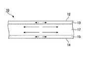
図2は、レーザ光を照射する前の強化ガラス板の残留応力の分布例を示す模式図である。図2は、化学強化法で強化された強化ガラス板(以下、「化学強化ガラス板」という)の残留応力の分布例を示す。図3は、レーザ光を照射する前の強化ガラス板の一例の断面図である。図3において、矢印の方向は、応力の作用方向を示し、矢印の大きさは、応力の大きさを示す。 FIG. 2 is a schematic diagram showing an example of residual stress distribution in the tempered glass plate before irradiation with laser light. FIG. 2 shows an example of residual stress distribution of a tempered glass sheet (hereinafter referred to as “chemically tempered glass sheet”) reinforced by a chemical tempering method. FIG. 3 is a cross-sectional view of an example of a tempered glass plate before irradiation with laser light. In FIG. 3, the direction of the arrow indicates the direction in which the stress is applied, and the size of the arrow indicates the magnitude of the stress.
図3に示すように、強化ガラス板10は、圧縮応力が残留する表面層13及び裏面層15と、表面層13と裏面層15との間に設けられ、引張応力が残留する中間層17とを有する。強化ガラス板10の端面の表層は、圧縮応力が残留する層のみで構成されても良いし、圧縮応力が残留する層と引張応力が残留する層とで構成されても良い。 As shown in FIG. 3, the tempered
図2に示すように、表面層13及び裏面層15に残留する圧縮応力(>0)は、強化ガラス板10の表面12及び裏面14から内部に向けて徐々に小さくなる傾向がある。化学強化の場合、図2に示すように、中間層17に残留する引張応力(>0)はほぼ一定である。 As shown in FIG. 2, the compressive stress (> 0) remaining on the
図2において、CSは表面層13や裏面層15における最大残留圧縮応力(表面圧縮応力)(>0)、CTは中間層17における内部残留引張応力(中間層17の残留引張応力の平均値)(>0)、DOLは表面層13や裏面層15の厚さをそれぞれ示す。CSやCT、DOLは、化学強化法の場合、ガラスを処理液(例えば、KNO3溶融塩)に浸漬してイオン交換するので、処理液の濃度や温度、浸漬時間などで調節可能である。なお、本実施形態の表面層13及び裏面層15は、同じ厚さ、同じ最大残留圧縮応力を有するが、異なる厚さを有しても良いし、異なる最大残留圧縮応力を有しても良い。In FIG. 2, CS is the maximum residual compressive stress (surface compressive stress) (> 0) in the
強化ガラス板10の表面12には、切断予定線に沿って、スクライブ線(溝線)が予め形成されていない。スクライブ線を予め形成しても良いが、この場合、工程数が増えるので、作業が繁雑である。また、スクライブ線を予め形成すると、ガラスが欠けることがある。 A scribe line (groove line) is not formed in advance on the
強化ガラス板10の端部には、切断開始位置に、初期クラックが予め形成されている。初期クラックの形成方法は、一般的な方法であって良く、例えばカッタやヤスリ、レーザで形成される。工程数を削減するため、初期クラックを予め形成しなくても良い。特に、強化ガラス板10の端部が切断前に予め回転砥石などで研削されている場合、研削時にマイクロクラックが形成されるので、初期クラックを予め形成しなくて良い。 An initial crack is formed in advance at the cutting start position at the end of the tempered
強化ガラス板10の表面12上において、レーザ光20の照射領域22(例えばレーザ光20の照射領域22の中心)は、強化ガラス板10の端部から内側に向けて、切断予定線に沿って、直線状や曲線状に移動される。これによって、強化ガラス板10の端部から内側に向けてクラック30(図1A及び図1B参照)を形成し、強化ガラス板10を切断する。レーザ光20の照射領域22は、P字状に移動されても良く、この場合、移動経路に含まれる切断予定線の終端は、切断予定線の途中と交わる。 On the
強化ガラス板10の表面12上において、レーザ光20の照射領域22を移動させるため、強化ガラス板10を支持する支持体を、移動または回転しても良いし、レーザ光20の光源を移動しても良い。また、レーザ光20の経路の途中に設けられるミラーを回転しても良い。 In order to move the
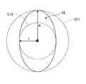
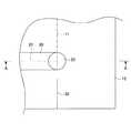
強化ガラス板10の表面12上において、レーザ光20の照射領域22は、例えば図1A及び図1Bに示すように、円状に形成されているが、矩形状や楕円状などであっても良く、その形状に制限はない。なお、照射領域22の真円度は0.5R以下が好ましい。真円度が0.5R以下であると、強化ガラス板10の表面12上で曲線形状の切断予定線に沿って照射領域22の中心を移動させるとき、照射領域22の回転制御の要求精度が低いので好ましい。また、照射領域22の回転制御の精度が同程度の場合、切断予定線の法線方向における照射領域22の幅の変化が小さくなるため、切断精度が高くなる。例えば、切断予定線の曲率半径が小さい場合であっても精度良く切断できる。より好ましくは、真円度が0.3R以下である。さらに好ましくは、真円度が0.2R以下である。ここで、真円度は、図4に示すように、照射領域22の外接円C11及び内接円C12である2つの同心円の半径R、rの差(R−r)である。なお、Rは照射領域22の外接円C11の半径を示し、rは照射領域22の内接円C12の半径を示す。 On the
強化ガラス板10の表面12上において、レーザ光20の照射領域22は、強化ガラス板10の厚さや、最大残留圧縮応力(CS)、内部残留引張応力(CT)、表面層13や裏面層15の厚さ(DOL)、レーザ光20の光源出力などに応じた速度で移動される。 On the
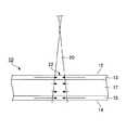
レーザ光20は、光源から出射された後、集光レンズなどで集光され、強化ガラス板10の表面12に結像される。レーザ光20の集光位置は、強化ガラス板10の表面12を基準として、光源側であっても良いし、裏面14側であっても良い。また、加熱温度が高くなりすぎない、すなわち徐冷点以下を保てる集光面積であれば、図5に示すように、レーザ光20の集光位置は強化ガラス板10中、特に中間層17内であっても良い。レーザ光20の集光位置が中間層17内にある場合、レーザ光20によって応力が発生する領域を最小にできるので、切断精度を高めることができるとともに、レーザ光20の光源出力を低減することができる。 The
レーザ光20は、強化ガラス板10を通過する過程で熱として吸収され、強度が低くなる。 The
そこで、裏面14におけるレーザ光20のパワー密度を高め、表面12の加熱温度と、裏面14の加熱温度との差を小さくするため、レーザ光20の集光位置は裏面14またはその近傍に設定されてもよい。表面12の加熱温度と、裏面14の加熱温度との差が小さいので、加熱効率が良く、レーザ光20の光源出力の低減が可能である。 Therefore, in order to increase the power density of the
レーザ光20の光軸21は、強化ガラス板10の表面12において、例えば図1A及び図5(図1Aでは光軸の図示を省略する)に示すように表面12と直交していても良いし、第3の実施形態で説明するように表面12と斜めに交わっていても良い。表面12で反射するレーザ光20が、レーザ発振器に影響を及ぼすおそれがある場合、レーザ光20の光軸21が表面12と斜めに交わると、ほとんどの反射光がレーザ発振器に戻らないため、影響を小さくすることができる。 The
従来の方法は、レーザ光のみの作用で切断するため、残留引張応力が大きな強化ガラスでは中間層の残留引張応力によるクラックが意図しない方向に急激に伸展し、所望の形状で切断できなかった。 Since the conventional method cuts only by the action of laser light, in the case of tempered glass having a large residual tensile stress, cracks due to the residual tensile stress of the intermediate layer suddenly extend in an unintended direction and could not be cut in a desired shape.
一方、本実施形態では、強化ガラス板10とレーザ光20とが後述の式を満たすことによって、レーザ光20のみの作用ではなく、中間層17の残留引張応力によるクラックの伸展を利用して強化ガラス板10を切断する。すなわち、詳しくは後述するが、上記条件でレーザ光20の照射領域22における中間層17を徐冷点以下の温度で加熱することによって、中間層17の残留引張応力によって強化ガラス板10に生じるクラック30の伸展を制御して、残留引張応力によるクラック30によって強化ガラス板10を切断することが可能となる。なお、中間層17を徐冷点以下の温度で加熱するのは、徐冷点を超えて加熱すると、レーザ光が通過する短時間でもガラスが高温となり粘性流動が発生しやすい状態となるため、この粘性流動によりレーザ光によって発生させた圧縮応力が緩和されるからである。 On the other hand, in the present embodiment, when the tempered
強化ガラス板10を通過するレーザ光20は、強化ガラス板10の表面12における強度をI0とし、強化ガラス板10中を距離L(cm)だけ移動したときのレーザ光20の強度をIとすると、I=I0×exp(−α×L)の式が成立する。この式は、ランベルト・ベールの法則と呼ばれるものである。αはレーザ光20に対する強化ガラス板10の吸収係数(cm−1)を表し、レーザ光20の波長や強化ガラス板10の化学組成などで決まる。The
レーザ光20は、強化ガラス板10の表面12に対して垂直に入射すると、強化ガラス板10の厚さt(cm)と同じ距離を移動して裏面14から出射する。この場合、強化ガラス板10とレーザ光20とが0<α×t≦3.0の式を満たすことによって、レーザ光20が強化ガラス板10の表面で吸収されずに内部にまで到達するようになる。強化ガラス板10の内部が十分に加熱され、強化ガラス板10に生じる応力は図3に示す状態から図6や図7に示す状態に変化する。 When the
図6は、図1BのA−A線に沿った断面における応力の分布例を示す模式図であって、レーザ光の照射領域を含む断面における応力の分布例を示す模式図である。図7は、図1BのB−B線に沿った断面における応力の分布例を示す模式図であって、図6に示す断面よりも後方の断面における応力の分布例を示す模式である。ここで、「後方」とは、レーザ光20の走査方向後方を意味する。図6及び図7において、矢印の方向は、応力の作用方向を示し、矢印の長さは、応力の大きさを示す。 FIG. 6 is a schematic diagram illustrating an example of stress distribution in a cross section along the line AA in FIG. 1B, and is a schematic diagram illustrating an example of stress distribution in a cross section including a laser light irradiation region. FIG. 7 is a schematic diagram illustrating an example of stress distribution in a cross section taken along line BB in FIG. 1B, and is a schematic diagram illustrating an exemplary stress distribution in a cross section behind the cross section illustrated in FIG. 6. Here, “rear” means the rear of the
レーザ光20の照射領域22における中間層17では、レーザ光20の強度が十分に高いので、温度が周辺に比べて高くなり、図2及び図3に示す残留引張応力よりも小さい引張応力、または、圧縮応力が生じる。残留引張応力よりも小さい引張応力、または、圧縮応力が生じている部分では、クラック30の伸展が抑制される。クラック30の伸展を確実に防止するため、図6に示すように、圧縮応力が生じていることが好ましい。 In the
なお、レーザ光20の照射領域22における表面層13や裏面層15では、図2及び図3に示す残留圧縮応力よりも大きい圧縮応力が生じているので、クラック30の伸展が抑制されている。 In addition, since the compressive stress larger than the residual compressive stress shown in FIG.2 and FIG.3 has arisen in the
図6に示す圧縮応力との釣り合いのため、図6に示す断面よりも後方の断面では、図7に示すように、中間層17に引張応力が生じる。この引張応力は、残留引張応力よりも大きく、引張応力が所定値に達している部分に、クラック30が形成される。クラック30は強化ガラス板10の表面12から裏面14まで貫通しており、本実施形態の切断は所謂フルカット切断である。 In order to balance with the compressive stress shown in FIG. 6, a tensile stress is generated in the
この状態で、レーザ光20の照射領域22を移動させると、強化ガラス板10の内部において照射領域22の位置が前述したように図6のような応力分布になっているため、クラック30が切断予定線から外れて自走するようなことはなく、照射領域22の位置に追従するようにクラック30の先端位置が移動する。従って、レーザ光20によってクラック30の伸展を制御できる。 In this state, when the
このように、本実施形態では、α×tを0より大きく3.0以下とすることで、強化ガラス板10において、レーザ光20によってクラック30の伸展を制御できる。そして、照射領域22の直後をクラック30が伸展するため、切断線が照射領域22の移動軌跡どおりに形成されるため、切断精度を向上できる。なお、クラック30の先端は、照射領域22の直後を追従するのでなく、照射領域22と重なって追従しても良い。クラック30の先端が照射領域22に近いほど、または重なっていることが切断精度をより向上させる。 Thus, in this embodiment, the extension of the
ガラスは、用途によっては、高い透明度が要求されるので、使用レーザ波長が可視光の波長領域に近い場合はα×tは0に近いほど良い。しかし、α×tは、小さすぎると吸収効率が悪くなるので、好ましくは0.0005以上(レーザ光吸収率0.05%以上)、より好ましくは0.002以上(レーザ光吸収率0.2%以上)、さらに好ましくは0.004以上(レーザ光吸収率0.4%以上)である。 Since high transparency is required for glass depending on the application, α × t is preferably closer to 0 when the laser wavelength used is close to the wavelength region of visible light. However, since α × t is too small, the absorption efficiency is deteriorated. Therefore, it is preferably 0.0005 or more (laser light absorption rate 0.05% or more), more preferably 0.002 or more (laser light absorption rate 0.2). % Or more), more preferably 0.004 or more (laser light absorption rate 0.4% or more).
ガラスは、用途によっては、逆に低い透明度が要求されるので、使用レーザ波長が可視光の波長領域に近い場合はα×tは大きいほど良い。しかし、α×tが大きすぎるとレーザ光の表面吸収が大きくなるのでクラック伸展を制御できなくなる。このため、α×tは、好ましくは3.0以下(レーザ光吸収率95%以下)、より好ましくは0.3以下(レーザ光吸収率26%以下)、さらに好ましくは0.105以下(レーザ光吸収率10%以下)、特に好ましくは0.02以下(レーザ光吸収率2%以下)である。 Glass, on the other hand, requires low transparency, so that when the used laser wavelength is close to the wavelength region of visible light, the larger α × t is better. However, if .alpha..times.t is too large, the surface absorption of the laser beam becomes large, and crack extension cannot be controlled. For this reason, α × t is preferably 3.0 or less (laser light absorptivity 95% or less), more preferably 0.3 or less (laser light absorptivity 26% or less), further preferably 0.105 or less (laser The light absorption rate is 10% or less), particularly preferably 0.02 or less (laser light absorption rate 2% or less).
ところで、本発明者の知見によると、中間層17の内部残留引張応力(CT)が30MPa以上になると、中間層17の残留引張応力のみで、強化ガラス板10に形成されたクラックが自然に伸展する(自走する)。 By the way, according to the knowledge of the present inventor, when the internal residual tensile stress (CT) of the
そこで、切断に使用される引張応力のうち、中間層17の残留引張応力が、レーザ光20によって発生する引張応力よりも支配的となるように、内部残留引張応力(CT)は、15MPa以上であることが好ましい。これによって、強化ガラス板10の内部において、引張応力が所定値に達する位置(即ち、クラック30の先端位置)と、レーザ光20の位置との間の距離が十分に短くなるので、切断精度を向上できる。 Therefore, the internal residual tensile stress (CT) is 15 MPa or more so that the residual tensile stress of the
中間層17の内部残留引張応力(CT)は、より好ましくは30MPa以上、さらに好ましくは40MPaである。内部残留引張応力(CT)が30MPa以上であると、切断に使用される引張応力は中間層17の残留引張応力のみとなり、切断線の軌跡精度をさらに向上できる。 The internal residual tensile stress (CT) of the
本実施形態の化学強化ガラスの切断において、内部残留引張応力(CT)の上限値は120MPaである。現在の技術では、強化処理の技術上の理由で、120MPa程度までしか強化できないが、内部残留引張応力(CT)が120MPaを超える化学強化ガラスを製造できれば、本発明を適用することも当然に可能である。 In the cutting of the chemically strengthened glass of the present embodiment, the upper limit value of the internal residual tensile stress (CT) is 120 MPa. In the current technology, it can be tempered only up to about 120 MPa for technical reasons of tempering treatment. However, if chemically tempered glass having an internal residual tensile stress (CT) exceeding 120 MPa can be produced, the present invention can naturally be applied. It is.
レーザ光20の光源としては、波長が800〜1100nmの近赤外線(以下、単に「近赤外線」という)のレーザが用いられる。近赤外線レーザとしては、例えば、Ybファイバーレーザ(波長:1000〜1100nm)、Ybディスクレーザ(波長:1000〜1100nm)、Nd:YAGレーザ(波長:1064nm)、高出力半導体レーザ(波長:808〜980nm)が挙げられる。これらの近赤外線レーザは、高出力で安価であり、また、α×tを所望の範囲に調整するのが容易である。 As the light source of the
なお、本実施形態では、レーザ光20の光源として高出力で安価な近赤外線レーザが用いられるが、光源の種類は多種多様であってよい。例えば、UVレーザ(波長:355nm)、グリーンレーザ(波長:532nm)、Ho:YAGレーザ(波長:2080nm)、Er:YAGレーザ(2940nm)、中赤外光パラメトリック発振器を使用したレーザ(波長:2600〜3450nm)などが挙げられる。また、レーザ光20の発振方式に制限はなく、レーザ光を連続発振するCWレーザ、レーザ光を断続発振するパルスレーザのいずれも使用可能である。また、レーザ光20の強度分布に制限はなく、ガウシアン型であっても、トップハット型であっても良い。 In this embodiment, a high-power and inexpensive near-infrared laser is used as the light source of the
図8は、強化ガラス板を精度良く切断できる、中心波長帯が1075〜1095nmのレーザ光の光源出力と、当該レーザ光に対する強化ガラス板の吸収係数(α)と強化ガラス板の厚さ(t)との積(α×t)との関係を示す図である。 FIG. 8 shows the light source output of a laser beam having a central wavelength band of 1075 to 1095 nm that can cut the tempered glass plate with high accuracy, the absorption coefficient (α) of the tempered glass plate with respect to the laser beam, and the thickness (t ) And the product (α × t).
図8に示すように、α×tが小さくなるほど、レーザ光20の熱変換効率が低くなるので、光源に要求される出力が大きくなる。そこで、出力が500W以下の汎用の近赤外線レーザを使用する目的で、α×tは0.001以上に設定されてよい。汎用の近赤外線レーザを使用するので、コストの低減が可能である。α×tは、より好ましくは0.002以上、さらに好ましくは0.003以上である。また、良好な切断精度を得るためα×tは、好ましくは3.0以下、より好ましくは0.3以下、さらに好ましくは0.105以下、特に好ましくは0.02以下である。 As shown in FIG. 8, as α × t becomes smaller, the thermal conversion efficiency of the
なお、吸収係数(α)は、レーザ光20の波長が800〜1100nmの範囲内の場合、レーザ光20の波長にほとんど依存しない。そのため、吸収係数(α)の測定には中心波長帯が1075〜1095nmのレーザ光が用いられ、切断用のレーザ光には波長が800nm以上1075nm未満のレーザ光、または波長が1095nmよりも長く1100nm以下のレーザ光が用いられてもよい。 The absorption coefficient (α) hardly depends on the wavelength of the
吸収係数(α)は、1000nm付近(800〜1100nm)の近赤外線波長領域では、強化ガラス板10のガラス組成などで定まる。強化ガラス板10中の鉄(Fe)の含有量、コバルト(Co)の含有量、銅(Cu)の含有量が多くなるほど、吸収係数(α)が大きくなる。さらに、強化ガラス板10中の希土類元素(例えばYb)の含有量が多くなるほど、希土類原子の吸収波長付近で吸収係数(α)が大きくなる。吸収係数(α)の調節にはガラスの透明性、及びコストの観点から鉄が用いられ、コバルト、銅、及び希土類元素は強化ガラス板10中に実質的に含まれていなくてよい。 The absorption coefficient (α) is determined by the glass composition of the tempered
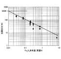
図9は、強化ガラス板を精度良く切断できる、中心波長帯が1075〜1095nmのレーザ光の光源出力と、強化ガラス板中の全FeをFe2O3換算したときFe含有量(以下、「Fe2O3含有量」という)との関係を示す図である。Fe2O3含有量が少なくなるほど、近赤外線に対する強化ガラス板10の吸収係数(α)が小さくなり、レーザ光20の熱変換効率が低くなるので、図9に示すように光源に要求される出力が大きくなる。FIG. 9 shows the light source output of a laser beam having a central wavelength band of 1075 to 1095 nm that can cut the tempered glass plate with high accuracy, and the Fe content when the total Fe in the tempered glass plate is converted to Fe2 O3 (hereinafter, “ it is a diagram showing the relationship between Fe2 that O3 content "). As the Fe2 O3 content decreases, the absorption coefficient (α) of the tempered
強化ガラス板10は鉄として2価の鉄イオン(Fe2+)と3価の鉄イオン(Fe3+)とを含んでおり、主にFe2+が近赤外線の吸収に寄与する。The tempered
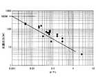
図10は、強化ガラス板を精度良く切断できる、中心波長帯が1075〜1095nmのレーザ光の光源出力と、強化ガラス板中のFe2+のFeO換算での含有量(以下、「Fe2+含有量」という)との関係を示す図である。Fe2+含有量が少なくなるほど、近赤外線に対する強化ガラス板10の吸収係数(α)が小さくなり、レーザ光20の熱変換効率が低くなるので、図10に示すように光源に要求される出力が大きくなる。従って、Fe2O3含有量が高くすることによってFe2+含有量を高くすることが重要である。しかしながら、ガラス中のFe2+とFe3+の割合は、ガラスの組成によって変化する。FIG. 10 shows the light source output of laser light having a central wavelength band of 1075 to 1095 nm that can cut the tempered glass plate with high accuracy, and the content of Fe2+ in the tempered glass plate in terms of FeO (hereinafter referred to as “Fe2+ content”). FIG. As the Fe2+ content decreases, the absorption coefficient (α) of the tempered
以下、本発明の強化ガラス板の各成分の組成範囲について説明する。 Hereinafter, the composition range of each component of the tempered glass sheet of the present invention will be described.
SiO2はガラスの骨格を構成する成分であり必須である。56%未満ではガラスとしての安定性が低下する、または耐候性が低下する。好ましくは58%以上、より好ましくは60%以上である。SiO2が75%超ではガラスの粘性が増大し溶融性が著しく低下する。好ましくは70%以下、より好ましくは68%以下である。SiO2 is a component constituting the skeleton of glass and essential. If it is less than 56%, the stability as a glass is lowered, or the weather resistance is lowered. Preferably it is 58% or more, More preferably, it is 60% or more. If the SiO2 content exceeds 75%, the viscosity of the glass increases and the meltability decreases significantly. Preferably it is 70% or less, More preferably, it is 68% or less.
Al2O3はイオン交換速度を向上させる成分であり、必須である。5%未満ではイオン交換速度が低下する。好ましくは7%以上、より好ましくは8%以上である。Al2O3が20%超ではガラスの粘性が高くなり均質な溶融が困難になる。好ましくは15%以下、より好ましくは12%以下、さらに好ましくは11%以下である。Al2 O3 is a component that improves the ion exchange rate and is essential. If it is less than 5%, the ion exchange rate decreases. Preferably it is 7% or more, More preferably, it is 8% or more. If Al2 O3 exceeds 20%, the viscosity of the glass becomes high and uniform melting becomes difficult. Preferably it is 15% or less, More preferably, it is 12% or less, More preferably, it is 11% or less.
B2O3は、イオン交換速度を向上させる、またはFe2+による近赤外線の吸収を小さくする成分であるが、歪点を低下させ応力緩和によって圧縮応力が小さくなるおそれがある成分である。
本発明の化学強化ガラス板の第1態様ではB2O3は必須ではないが3%未満の範囲で含有してもよい。3%以上ではFe2+による近赤外線の吸収が小さくなるおそれがあり、好ましくは2%以下、より好ましくは1%以下である。
本発明の化学強化ガラス板の第2態様ではB2O3は必須である。3%未満ではイオン交換速度が低下するおそれがあり、好ましくは5%以上である。20%超では歪点が低下して応力緩和によって圧縮応力が小さくなるおそれがあり、好ましくは15%以下、より好ましくは10%以下、さらに好ましくは8%以下である。
SiO2、Al2O3及びB2O3の含有量の合計は80%以下であることが好ましい。80%超では高温でのガラスの粘性が増大し、溶融が困難となるおそれがある。より好ましくは78%以下である。また、同合計は66%以上であることが好ましい。66%未満では安定なガラスが得られにくくなったり、耐候性が低下しやすくなったりするおそれがあり、68%以上であるこがより好ましい。B2 O3 is a component that improves the ion exchange rate or reduces near infrared absorption by Fe2+ , but it is a component that lowers the strain point and may reduce the compressive stress due to stress relaxation.
In the first aspect of the chemically strengthened glass sheet of the present invention, B2 O3 is not essential, but may be contained in a range of less than 3%. If it is 3% or more, the absorption of near infrared rays by Fe2+ may be small, preferably 2% or less, more preferably 1% or less.
In the second aspect of the chemically strengthened glass plate of the present invention, B2 O3 is essential. If it is less than 3%, the ion exchange rate may decrease, and it is preferably 5% or more. If it exceeds 20%, the strain point may be lowered and the compression stress may be reduced by stress relaxation, and is preferably 15% or less, more preferably 10% or less, and further preferably 8% or less.
The total content of SiO2 , Al2 O3 and B2 O3 is preferably 80% or less. If it exceeds 80%, the viscosity of the glass at a high temperature increases and melting may be difficult. More preferably, it is 78% or less. The total is preferably 66% or more. If it is less than 66%, it is difficult to obtain a stable glass or the weather resistance tends to be lowered, and it is more preferably 68% or more.
Na2Oはイオン交換により表面圧縮応力層を形成させ、またガラスの溶融性を向上させる成分であり、必須である。8%未満ではイオン交換により所望の表面圧縮応力層を形成することが困難となる。好ましくは10%以上、より好ましくは12%以上、さらに好ましくは13%以上である。 Na2Oが22%超ではTgしたがって歪点が低くなる、または耐候性が低下する。好ましくは18%以下、より好ましくは17%以下、さらに好ましくは14%以下である。Na2 O is a component that forms a surface compressive stress layer by ion exchange and improves the meltability of the glass, and is essential. If it is less than 8%, it becomes difficult to form a desired surface compressive stress layer by ion exchange. Preferably it is 10% or more, More preferably, it is 12% or more, More preferably, it is 13% or more. If Na2 O exceeds 22%, Tg and therefore the strain point is lowered, or the weather resistance is lowered. Preferably it is 18% or less, More preferably, it is 17% or less, More preferably, it is 14% or less.
K2Oは必須ではないが、溶融性を向上させる成分であるとともに、化学強化におけるイオン交換速度を大きくするための成分であり、10%以下の範囲で含有してもよい。10%超では耐候性が低下する。好ましくは5%以下、より好ましくは4%以下、さらに好ましくは3%以下である。K2Oを含有する場合その含有量は1%以上であることが好ましい。1%未満では溶融性またはイオン交換速度を向上させる効果が小さく、より好ましくは2%以上である。K2 O is not essential, but is a component for improving the meltability and a component for increasing the ion exchange rate in chemical strengthening, and may be contained in a range of 10% or less. If it exceeds 10%, the weather resistance decreases. Preferably it is 5% or less, More preferably, it is 4% or less, More preferably, it is 3% or less. When K2 O is contained, the content is preferably 1% or more. If it is less than 1%, the effect of improving the meltability or ion exchange rate is small, more preferably 2% or more.
Na2O及びK2Oの含有量の合計R2Oは所望のイオン交換特性を得るために11%以上であることが好ましい。より好ましくは13%以上、さらに好ましくは15%以上である。また、R2Oは22%以下であることが好ましい。R2Oが22%超ではガラスの耐候性をはじめとする化学的耐久性が低くなるおそれがある。より好ましくは20%以下、さらに好ましくは18%以下である。The total R2 O content of Na2 O and K2 O is preferably 11% or more in order to obtain desired ion exchange characteristics. More preferably, it is 13% or more, More preferably, it is 15% or more. R2 O is preferably 22% or less. If R2 O exceeds 22%, the chemical durability including the weather resistance of the glass may be lowered. More preferably, it is 20% or less, More preferably, it is 18% or less.
Li2Oは歪点を低くして応力緩和を起こりやすくし、その結果安定した表面圧縮応力層を得られなくする成分であるので含有しないことが好ましく、含有する場合であってもその含有量は2%以下であることが好ましく、より好ましくは0.05%以下、特に好ましくは0.01%未満である。Li2 O is a component that lowers the strain point to facilitate stress relaxation, and as a result makes it impossible to obtain a stable surface compressive stress layer, so it is preferably not contained, and even if it is contained, its content Is preferably 2% or less, more preferably 0.05% or less, and particularly preferably less than 0.01%.
アルカリ土類金属酸化物は溶融性を向上させる成分であるとともに、Tgしたがって歪点の調節に有効な成分である。
BaOはアルカリ土類金属酸化物の中でイオン交換速度を低下させる効果が最も大きいので、BaOは含有しないこととするか、含有する場合であってもその含有量は1%未満とすることが好ましい。
SrOは必要に応じて含有してもよいが、MgO、CaOに比べてイオン交換速度を低下させる効果が大きいので含有する場合であってもその含有量は1%未満であることが好ましい。
SrOまたはBaOを含有する場合それらの含有量の合計は3%以下であることが好ましく、より好ましくは2%未満、さらに好ましくは1%未満である。Alkaline earth metal oxides are components that improve the meltability, and are effective components for adjusting the Tg and therefore the strain point.
Since BaO has the greatest effect of reducing the ion exchange rate among alkaline earth metal oxides, BaO should not be contained, or even if contained, its content should be less than 1%. preferable.
SrO may be contained as necessary, but since the effect of lowering the ion exchange rate is greater than that of MgO and CaO, the content is preferably less than 1% even when contained.
When SrO or BaO is contained, the total content thereof is preferably 3% or less, more preferably less than 2%, still more preferably less than 1%.
MgOはイオン交換速度を低下させる効果が比較的小さいものであり、溶融性を改善するために14%以下の範囲で含有してもよい。14%超ではイオン交換速度が低下する。好ましくは9%以下、より好ましくは7%以下である。
MgOを含有する場合その含有量は、好ましくは3%以上、より好ましくは4%以上、さらに好ましくは6%以上である。
CaOはMgOに次いでイオン交換速度を低下させる効果が比較的小さいものであり、溶融性を改善する等のために5%以下の範囲で含有してもよい。5%超ではイオン交換速度が低下する。好ましくは3%以下、さらに好ましくは1%以下である。CaOを含有する場合、その含有量は典型的には0.5%以上であることが好ましい。
CaOを含有する場合MgOを含有することが好ましく、その場合MgO含有量はCaO含有量以上であることが好ましい。MgO has a relatively small effect of lowering the ion exchange rate, and may be contained in a range of 14% or less in order to improve the meltability. If it exceeds 14%, the ion exchange rate decreases. Preferably it is 9% or less, More preferably, it is 7% or less.
When MgO is contained, its content is preferably 3% or more, more preferably 4% or more, and even more preferably 6% or more.
CaO has a relatively small effect of lowering the ion exchange rate next to MgO, and may be contained in a range of 5% or less in order to improve the meltability. If it exceeds 5%, the ion exchange rate decreases. Preferably it is 3% or less, More preferably, it is 1% or less. When CaO is contained, its content is preferably 0.5% or more typically.
When it contains CaO, it is preferable to contain MgO, and in that case, it is preferable that MgO content is more than CaO content.
アルカリ土類金属酸化物の含有量の合計ROは14%以下であることが好ましい。14%超ではイオン交換速度が低下する、失透しやすくなる、または歪点が低くなりすぎるおそれがある。より好ましくは10%以下、さらに好ましくは8%以下である。4%未満では溶融性が低下する、または歪点の調節が困難になる。好ましくは5%以上、より好ましくは6%以上である。
MgO及びCaOの含有量の合計MgO+CaOは4〜14%であることが好ましい。より好ましくは5〜10%である。The total RO of the alkaline earth metal oxide content is preferably 14% or less. If it exceeds 14%, the ion exchange rate tends to be low, devitrification tends to occur, or the strain point may be too low. More preferably, it is 10% or less, More preferably, it is 8% or less. If it is less than 4%, the meltability is lowered, or the adjustment of the strain point becomes difficult. Preferably it is 5% or more, more preferably 6% or more.
The total MgO + CaO content of MgO and CaO is preferably 4 to 14%. More preferably, it is 5 to 10%.
本発明のガラスのうち母ガラスに相当する部分は本質的に以上で説明した成分からなるが、本発明の目的を損なわない範囲でその他の成分を含有してもよい。そのような成分を含有する場合、それら成分の含有量の合計は10%以下であることが好ましく、典型的には5%以下である。以下、上記その他成分について例示的に説明する。 The portion of the glass of the present invention corresponding to the mother glass consists essentially of the components described above, but may contain other components as long as the object of the present invention is not impaired. When such components are contained, the total content of these components is preferably 10% or less, and typically 5% or less. Hereinafter, the other components will be described as an example.
ZrO2はイオン交換速度を大きくする成分であり、例えば3%までの範囲で含有してもよい場合がある。3%超ではイオン交換速度を大きくする効果が飽和し、また、溶融性が悪化して未溶融物としてガラス中に残る場合が起こる恐れがある。より好ましくは2%以下である。ZrO2を含有する場合、その含有量は好ましくは0.5%以上、より好ましくは1%以上である。ZrO2 is a component that increases the ion exchange rate, and may be contained, for example, in a range of up to 3%. If it exceeds 3%, the effect of increasing the ion exchange rate is saturated, and there is a possibility that the meltability deteriorates and remains in the glass as an unmelted product. More preferably, it is 2% or less. When ZrO2 is contained, its content is preferably 0.5% or more, more preferably 1% or more.
ZnOはガラスの高温での溶融性を向上するために例えば2%まで含有してもよい場合があるが、好ましくは1%以下である。フロート法で製造する場合などには0.5%以下にすることが好ましい。0.5%超ではフロート成型時に還元し製品欠点となるおそれがある。典型的にはZnOは含有しない。
TiO2はガラス中に存在するFeイオン(Fe2+、Fe3+)の酸化還元状態を変化させ可視光透過率が変化してガラスが着色するおそれがあるので、含有するとしても1%以下であることが好ましく、典型的には含有しない。ZnO may be contained, for example, up to 2% in order to improve the melting property of the glass at a high temperature, but it is preferably 1% or less. In the case of producing by the float process, etc., it is preferably 0.5% or less. If it exceeds 0.5%, it may be reduced during float molding, resulting in a product defect. Typically no ZnO is contained.
Since TiO2 changes the redox state of Fe ions (Fe2+ , Fe3+ ) present in the glass and the visible light transmittance may change, and the glass may be colored. It is preferred and typically not contained.
本発明の強化ガラス板では、ガラスの溶融の際の清澄剤としてSnO2が用いられる。これにより、泡などのインクルージョンが少なく、かつ均質性に優れるガラスを得ることができる。ガラスの清澄剤としては、SO3、塩化物、フッ化物などがあるが、SO3を用いる場合は、均質性を得るためにガラス融液の撹拌を行った場合に、リボイル泡が発生するおそれがある。また、塩化物やフッ化物を単独で用いる場合は、その含有量が増えるため、成分の揮発により均質なガラスが得られない恐れがある。In the tempered glass sheet of the present invention, SnO2 is used as a fining agent when the glass is melted. Thereby, the glass which has few inclusions, such as a bubble, and is excellent in homogeneity can be obtained. As a glass refining agent, there are SO3 , chloride, fluoride and the like, but when SO3 is used, reboil bubbles may be generated when the glass melt is stirred to obtain homogeneity. There is. In addition, when chloride or fluoride is used alone, its content increases, and there is a risk that a homogeneous glass cannot be obtained due to volatilization of the components.
ガラス中の全SnをSnO2換算したときSn含有量(以下、「SnO2含有量」という)は0.03質量%以上である。0.03質量%未満では、清澄剤としての効果が小さく、ガラス中の泡が取りきれない。好ましくは0.05質量%以上、より好ましくは0.08質量%以上、さらに好ましくは0.15質量%以上である。SnO2含有量が1%超だと、Feイオン(Fe2+、Fe3+)の酸化還元状態を変化させ、Fe2+含有量が小さくなりすぎる。0.7%以下が好ましく、0.5%以下がより好ましい。When all Sn in the glass is converted to SnO2 , the Sn content (hereinafter referred to as “SnO2 content”) is 0.03% by mass or more. If it is less than 0.03 mass%, the effect as a fining agent is small, and the bubble in glass cannot be removed. Preferably it is 0.05 mass% or more, More preferably, it is 0.08 mass% or more, More preferably, it is 0.15 mass% or more. If the SnO2 content exceeds 1%, the redox state of Fe ions (Fe2+ , Fe3+ ) is changed, and the Fe2+ content becomes too small. 0.7% or less is preferable, and 0.5% or less is more preferable.
SnO2と共に塩化物やフッ化物を加えることは、ガラス溶融時に用いる白金との界面に発生する泡を抑制するために行ってもよい。この場合、ClやFの含有量は0.01〜0.2質量%であることが好ましい。Adding chloride or fluoride together with SnO2 may be performed to suppress bubbles generated at the interface with platinum used during glass melting. In this case, the content of Cl or F is preferably 0.01 to 0.2% by mass.
本発明の強化ガラス板の第1の態様では、レーザ切断を行うために、強化ガラス板中の全FeをFe2O3換算したときFe含有量(Fe2O3含有量)が0.03〜0.2質量%であることが好ましい。ガラス中のSnはFeイオン(Fe2+、Fe3+)の酸化還元状態を変化させるが、Fe2O3含有量が0.03質量%以上だとレーザ切断を行いやすくなる。より好ましくは0.04質量%以上、さらに好ましくは0.06質量%以上である。0.2質量%超だと着色が問題となるおそれがある。より好ましくは0.15質量%以下、さらに好ましくは0.12質量%以下、特に好ましくは0.08質量%以下である。In a first aspect of the tempered glass of the present invention, in order to carry out laser cutting, Fe content when the total Fe in the tempered glass sheet in convertedFe 2 O 3 (Fe 2 O 3 content) 0.03 It is preferable that it is -0.2 mass%. Sn in the glass changes the redox state of Fe ions (Fe2+ , Fe3+ ), but laser cutting becomes easier when the Fe2 O3 content is 0.03% by mass or more. More preferably, it is 0.04 mass% or more, More preferably, it is 0.06 mass% or more. If it exceeds 0.2% by mass, coloring may cause a problem. More preferably, it is 0.15 mass% or less, More preferably, it is 0.12 mass% or less, Most preferably, it is 0.08 mass% or less.
また、同態様ではFe2+のFeO換算での含有量すなわちFe2+含有量(FeO含有量)は0.01〜0.2質量%である。0.01質量%未満だと近赤外線に対する強化ガラス板10の吸収係数(α)が小さくなり、レーザ光20の熱変換効率が低くなるので、図10に示すように光源に要求される出力が大きくなる。好ましくは0.02質量%以上、さらに好ましくは0.03質量%以上である。0.2質量%超だとα×tが3.0より大きくなりやすく、厚板を切断しにくくなる。好ましくは0.15質量%以下、より好ましくは0.12質量%以下、さらに好ましくは0.08質量%以下である。In the same embodiment, the Fe2+ content in terms of FeO, that is, the Fe2+ content (FeO content) is 0.01 to 0.2% by mass. If it is less than 0.01% by mass, the absorption coefficient (α) of the tempered
本発明の強化ガラス板の第2の態様では、レーザ切断を行うために、強化ガラス板中の前記Fe2O3含有量が0.1〜1.0質量%であることが好ましい。ガラス中のSnはFeイオン(Fe2+、Fe3+)の酸化還元状態を変化させ、またガラス中のB(B2O3)は近赤外線の吸収を小さくするが、Fe2O3含有量が0.1質量%以上だとレーザ切断を行いやすくなる。より好ましくは0.12質量%以上、さらに好ましくは0.14質量%以上、特に好ましくは0.2質量%以上である。1.0質量%超だと着色が問題となるおそれがある。より好ましくは0.8質量%以下、さらに好ましくは0.5質量%以下、特に好ましくは0.3質量%以下である。In a second aspect of the tempered glass of the present invention, in order to carry out laser cutting, it is preferable that the Fe2 O3 content of the tempered glass sheet in the 0.1 to 1.0 wt%. Sn in the glass changes the redox state of Fe ions (Fe2+ , Fe3+ ), and B (B2 O3 ) in the glass reduces near-infrared absorption, but the Fe2 O3 content is small. When the content is 0.1% by mass or more, it becomes easy to perform laser cutting. More preferably, it is 0.12 mass% or more, More preferably, it is 0.14 mass% or more, Most preferably, it is 0.2 mass% or more. If it exceeds 1.0% by mass, coloring may become a problem. More preferably, it is 0.8 mass% or less, More preferably, it is 0.5 mass% or less, Most preferably, it is 0.3 mass% or less.
また、同態様では前記FeO含有量は0.05〜1.0質量%である。0.05質量%未満だと近赤外線に対する強化ガラス板10の吸収係数(α)が小さくなり、レーザ光20の熱変換効率が低くなるので、図10に示すように光源に要求される出力が大きくなる。好ましくは0.06質量%以上、より好ましくは0.07質量%以上、さらに好ましくは0.1質量%以上である。1.0質量%超だとα×tが3.0より大きくなりやすく、厚板を切断しにくくなる。好ましくは0.8質量%以下、より好ましくは0.5質量%以下、さらに好ましくは0.3質量%以下である。 In the same embodiment, the FeO content is 0.05 to 1.0 mass%. If it is less than 0.05% by mass, the absorption coefficient (α) of the tempered
ガラス中の全FeをFeO換算したときFe含有質量に対するFe2+のFeO換算重量の割合(Redox)は20%以上であることが好ましい。20%未満ではFe2+含有量が小さくなり、近赤外線に対する強化ガラス板10の吸収係数(α)が小さくなり、レーザ光20の熱変換効率が低くなるので、図10に示すように光源に要求される出力が大きくなる。より好ましくは30%以上、さらに好ましくは40%以上、特に好ましくは50%以上である。When the total Fe in the glass is converted to FeO, the ratio (Redox) of Fe2+ weight of Fe2+ to Fe-containing mass is preferably 20% or more. If it is less than 20%, the Fe2+ content becomes small, the absorption coefficient (α) of the tempered
本発明の化学強化ガラス板は、フロート法、オーバーフローダウンドロー法(フュージョン法)、スロットダウンドロー法、ロールアウト法、等の周知の板ガラス製造方法により作製された板ガラスを用いることが好ましい。 As the chemically strengthened glass plate of the present invention, it is preferable to use a plate glass produced by a well-known plate glass manufacturing method such as a float method, an overflow downdraw method (fusion method), a slot downdraw method, or a rollout method.
本発明の化学強化ガラス板は、レートクール法で求められるガラス転移点付近の平均冷却速度が200℃/分以下であるガラス板を化学強化して得られることが好ましい。ガラス中のSnとFeの酸化還元反応は温度域によって変化するため、冷却速度によってそれぞれの価数が変化する。高温ではSn4+が還元されてSn2+になり酸素を放出してガラス中の泡を膨らませる効果があるが、同時にFe2+がFe3+になるため、Fe2+含有量が小さくなる。そのまま急冷すると、結果的にFe2+含有量の小さなガラスとなる。逆に、冷却速度が遅いと冷却過程でSn2+がSn4+になるとともにFe3+がFe2+になり、Fe2+含有量の大きなガラスとなる。平均冷却速度が200℃/分超だと、上記メカニズムによりFe2+含有量が小さくなりすぎるおそれがある。より好ましくは100℃/分以下、さらに好ましくは50℃/分以下である。平均冷却速度が0.5℃/分未満だと生産性が悪化するので好ましくない。より好ましくは1℃/分以上、さらに好ましくは10℃/分以上である。The chemically strengthened glass plate of the present invention is preferably obtained by chemically strengthening a glass plate having an average cooling rate near the glass transition point determined by the rate cool method of 200 ° C./min or less. Since the redox reaction of Sn and Fe in the glass changes depending on the temperature range, the respective valences change depending on the cooling rate. At high temperatures, Sn4+ is reduced to Sn2+ to release oxygen and expand bubbles in the glass, but at the same time Fe2+ becomes Fe3+ , so the Fe2+ content is reduced. If cooled as it is, the result is a glass with a small Fe2+ content. Conversely, if the cooling rate is slow, Sn2+ becomes Sn4+ and Fe3+ becomes Fe2+ during the cooling process,resulting in a glass with a large Fe2+ content. If the average cooling rate exceeds 200 ° C./min, the Fe2+ content may be too small due to the above mechanism. More preferably, it is 100 degrees C / min or less, More preferably, it is 50 degrees C / min or less. An average cooling rate of less than 0.5 ° C./min is not preferable because productivity deteriorates. More preferably, it is 1 degreeC / min or more, More preferably, it is 10 degreeC / min or more.
レートクール法で求められるガラス転移点付近の平均冷却速度は、より具体的には以下のような手順で求められる。ガラスをガラス転移点より100℃高い温度にて10分間保持後、一定冷却速度にて冷却する実験を、10℃/分、30℃/分、100℃/分、300℃/分、1000℃/分にて実施し、すべてのガラスの屈折率を測定することで、屈折率と冷却速度の関係を検量線として得ることができる。その後、実際のサンプルの屈折率を測定し、検量線から冷却速度を求める。 More specifically, the average cooling rate near the glass transition point determined by the rate cool method is determined by the following procedure. An experiment in which the glass was held at a
[第2の実施形態]
図11は、本発明の第2の実施形態に係る強化ガラス板の切断方法の説明図である。図11において、図1Aと同一構成には同一符号を付して説明を省略する。[Second Embodiment]
FIG. 11 is an explanatory diagram of a method for cutting a tempered glass sheet according to the second embodiment of the present invention. In FIG. 11, the same components as those in FIG.
本実施形態では、第1の実施形態と同様に、強化ガラス板10の表面12にレーザ光20を照射し、強化ガラス板10の表面12上で、レーザ光20の照射領域22を移動させることで、強化ガラス板10を切断する。 In the present embodiment, similarly to the first embodiment, the
また、本実施形態では、強化ガラス板10とレーザ光20とが、レーザ光20に対する強化ガラス板10の吸収係数をα(cm−1)とし、強化ガラス板10の厚さをt(cm)として、0<α×t≦3.0の式を満たすことによって、中間層17の残留引張応力よるクラックの伸展を利用して強化ガラス板10を切断する。すなわち、レーザ光20の照射領域22における中間層17を徐冷点以下の温度で加熱することによって、中間層17の残留引張応力によって強化ガラス板10に生じるクラック30の伸展を制御することが可能となる。従って、本実施形態でも、第1の実施形態と同様の効果が得られる。In the present embodiment, the tempered
これに加えて、本実施形態では、図11に示すように、強化ガラス板10の表面12にガス40を吹き付け、強化ガラス板10の表面12上でガス40の吹き付け領域42をレーザ光20の照射領域22と連動して(照射領域22と共に)移動させる。吹き付け領域42は、照射領域22と重なっていても良いし、照射領域22の近傍に配されても良い。また、吹き付け領域42は、照射領域22に先行しても良いし、照射領域22に追従しても良い。ガス40としては、特に限定されないが、例えば圧縮空気などが用いられる。 In addition to this, in this embodiment, as shown in FIG. 11, the
圧縮空気によって、強化ガラス板10の表面12に付着している付着物(例えば粉塵)を吹き飛ばして、付着物がレーザ光20を吸収するのを防止できる。よって、強化ガラス板10の表面12が過熱されるのを防止できる。 It is possible to prevent the adhered matter from absorbing the
ガス40は、強化ガラス板10を局所的に冷却する冷却ガスであっても良く、この場合、ガス40の吹き付け領域42は、図11に示すようにレーザ光20の照射領域22の移動方向後方近傍に位置するように、照射領域22に追従させても良い。これによって、レーザ光20の照射領域22の移動方向後方近傍において、高い温度勾配が生じるので、引張応力が所定値に達する位置(即ち、クラック30の先端位置)と、レーザ光20の位置との間の距離が短くなる。よって、クラック30の位置制御性が高まるため、切断精度をさらに向上できる。 The
[第3の実施形態]
図12A及び図12Bは、本発明の第3の実施形態に係る強化ガラス板の切断方法の説明図である。図12Aは、図12BのA−A線に沿った断面図である。図12Bは、強化ガラス板の平面図である。図12A及び図12Bにおいて、図1A等と同一構成には同一符号を付して説明を省略する。[Third Embodiment]
12A and 12B are explanatory views of a method for cutting a strengthened glass sheet according to the third embodiment of the present invention. 12A is a cross-sectional view taken along line AA in FIG. 12B. FIG. 12B is a plan view of the tempered glass sheet. 12A and 12B, the same components as those in FIG.
上記第1の実施形態ではレーザ光20が強化ガラス板10の表面12に対して垂直に入射するのに対し、本実施形態ではレーザ光20が強化ガラス板10の表面12に対して斜めに入射する点で相違する。その他の構成は第1の実施形態と同様であるので、相違点を中心に説明する。 In the first embodiment, the
レーザ光20の照射領域22の移動方向視で、図12Aに示すようにレーザ光20が強化ガラス板10の表面12に斜めに入射するので、強化ガラス板10の切断面が板厚方向に対して斜めになる。よって、強化ガラス板10の切断で得られる切断片同士の板厚方向への分離が可能である。 Since the
レーザ光20の光軸21の入射角βが大きくなるほど、スネルの法則に従って屈折角γが大きくなるので、強化ガラス板10の切断面の板厚方向に対する傾きが大きくなる。この傾きが大きくなるほど、切断後の板厚方向への分離が容易となるが、切断後の切断面の面取り加工が面倒になる。 As the incident angle β of the
入射角βは、レーザ光20の光軸21と、強化ガラス板10の表面12における切断予定線11との位置関係に応じて設定される。例えば図12Bに示すように平面視(板厚方向視)でレーザ光20の光軸21が切断予定線11に対して垂直に配置される場合、入射角βは1〜60°の範囲内で設定される。なお、平面視(板厚方向視)で、レーザ光20の光軸21は、切断予定線11に対して斜めに配置されても良い。 The incident angle β is set according to the positional relationship between the
レーザ光20は、強化ガラス板10の表面12に対して斜めに入射すると、t/cosγの距離を移動して裏面14から出射する。この場合、強化ガラス板10とレーザ光20とが0<α×t/cosγ≦3.0の式を満たすことによって、レーザ光20が強化ガラス板10の表面12近傍で吸収されずに内部にまで到達するようになる。従って、第1の実施形態と同様に、中間層17の残留引張応力によって強化ガラス板10に生じるクラック30の伸展を制御することが可能となる。従って、本実施形態でも、第1の実施形態と同様の効果が得られる。 When the
なお、屈折角γが3°以下の場合、cosγ=1と近似することができるので、0<α×t≦3.0の式が成立すればよい。レーザ光20が近赤外線の場合、0.001≦α×t≦3.0の式が成立すればよい。また、吸収係数(α)の測定には中心波長帯が1075〜1095nmのレーザ光が用いられ、切断用のレーザ光には波長が800nm以上1075nm未満のレーザ光、または波長が1095nmよりも長く1100nm以下のレーザ光が用いられてもよい。 When the refraction angle γ is 3 ° or less, it can be approximated as cos γ = 1, and therefore, an equation of 0 <α × t ≦ 3.0 may be satisfied. When the
なお、本実施形態において、第2の実施形態と同様に、強化ガラス板10の表面12にガス40を吹き付け、強化ガラス板10の表面12上でガス40の吹き付け領域42をレーザ光20の照射領域22と連動して移動させても良い。ガス40の吹き付け領域42は、レーザ光20の照射領域22と重なっていても良いし、レーザ光20の照射領域22の近傍に配されても良い。また、ガス40の吹き付け領域42の外縁よりも内側に、レーザ光20の照射領域22が配置されても良い。 In the present embodiment, similarly to the second embodiment, the
以下に、実施例などにより本発明を具体的に説明するが、本発明はこれらの例によって限定されるものではない。 EXAMPLES The present invention will be specifically described below with reference to examples, but the present invention is not limited to these examples.
(化学強化用ガラス板)
化学強化用ガラス板を作製するため、複数種類の原料を混ぜて、白金坩堝を用いて1600℃の温度で1時間溶解した。白金スターラーにて撹拌をした後、カーボン板状に流し出し、ガラス転移点+30℃にて1時間保持後、1℃/分で冷却を行った。得られたガラスを切断、切削、両面鏡面研磨することにより、所望の厚さを有する50mm×50mmのガラス板を作製した。なお、ガラス原料を高温で溶解する際、溶融ガラスに含まれる3価の鉄の一部が2価の鉄に還元され、Fe2+含有量が増える。(Glass plate for chemical strengthening)
In order to produce a glass plate for chemical strengthening, a plurality of types of raw materials were mixed and melted at a temperature of 1600 ° C. for 1 hour using a platinum crucible. After stirring with a platinum stirrer, it was poured into a carbon plate, held at glass transition point + 30 ° C. for 1 hour, and then cooled at 1 ° C./min. The obtained glass was cut, cut, and mirror polished on both sides to produce a 50 mm × 50 mm glass plate having a desired thickness. In addition, when melt | dissolving a glass raw material at high temperature, a part of trivalent iron contained in molten glass is reduce |restored to bivalent iron, and Fe2+ content increases.
各化学強化用ガラス板中の組成は蛍光X線分析装置(理学電気工業株式会社製、ZSX100e)で測定し、湿式分析法で求めたFe2O3含有量を基に校正した。湿式分析法で求めたFe2O3含有量は蛍光X線分析装置で測定したFe2O3含有量よりも測定精度が高いので、湿式分析法で求めたFe2O3含有量を真の値として蛍光X線分析装置で求めたガラス組成を補正した。湿式分析法では、先ず、得られたガラスを粉砕し、粉砕したガラス粉末を、HF水溶液にて溶解し、試験液体を作製した。この試験液体と、2,2’−ジピリジル溶液と、酢酸アンモニウム溶液とを混合して発色させ、その吸光ピーク強度を測定し、標準試料により事前に作成した検量線を基にFe2+含有量を算出する。また、上記の試験液体と、ヒドロキシルアミン塩酸溶液と、2,2’−ジピリジル溶液と、酢酸アンモニウム溶液とを混合して全ての鉄を2価の鉄に還元して発色させ、その吸光ピーク強度を測定し、全鉄量(全ての鉄を2価の鉄の酸化物で換算したときの鉄の含有量)を算出する。算出された全鉄量からFe2O3含有量(全ての鉄を3価の鉄の酸化物で換算したときの鉄の含有量)が求められる。しかし、Snを含有する場合は湿式分析法ではFe2+含有量を求めることができない。そこで、Fe2+含有量は、同組成のSnを実質的に含有しないガラスにてあらかじめ求められた950nmの吸収係数のFe2+含有量依存性を用いて求めた。The composition in each glass plate for chemical strengthening was measured with a fluorescent X-ray analyzer (manufactured by Rigaku Denki Kogyo Co., Ltd., ZSX100e) and calibrated based on the content of Fe2 O3 obtained by a wet analysis method. Since Fe2 O3 content determined by a wet analysis method has high measurement accuracy than Fe2 O3 content measured by fluorescent X-ray analyzer, Fe2 O3 content of the true determined by a wet analysis The glass composition obtained with a fluorescent X-ray analyzer was corrected as a value. In the wet analysis method, first, the obtained glass was pulverized, and the pulverized glass powder was dissolved in an HF aqueous solution to prepare a test liquid. This test liquid, 2,2'-dipyridyl solution, and ammonium acetate solution are mixed to develop color, the absorption peak intensity is measured, and the Fe2+ content is determined based on a calibration curve prepared in advance using a standard sample. calculate. In addition, the above test liquid, hydroxylamine hydrochloric acid solution, 2,2′-dipyridyl solution, and ammonium acetate solution are mixed to reduce the color of all iron to divalent iron and develop a color. Is measured, and the total iron amount (the iron content when all irons are converted to divalent iron oxides) is calculated. From the calculated total iron amount, the Fe2 O3 content (the iron content when all the irons are converted into trivalent iron oxides) is determined. However, when Sn is contained, the Fe2+ content cannot be obtained by wet analysis. Therefore, the Fe2+ content was determined using the Fe2+ content dependency of the absorption coefficient of 950 nm obtained in advance for a glass containing substantially no Sn.
(化学強化ガラス板)
各化学強化ガラス板は、上記の化学強化用ガラス板をKNO3溶融塩に浸漬し、イオン交換処理した後、室温付近まで冷却することにより作製した。KNO3溶融塩の温度や浸漬時間などの処理条件は、内部残留引張応力(CT)が所望の値となるように設定した。(Chemical tempered glass plate)
Each chemically strengthened glass plate was produced by immersing the above-described chemically strengthened glass plate in KNO3 molten salt, performing an ion exchange treatment, and then cooling to near room temperature. The treatment conditions such as the temperature and immersion time of the KNO3 molten salt were set so that the internal residual tensile stress (CT) was a desired value.
各化学強化ガラス板の内部残留引張応力(CT)は、表面応力計FSM−6000(折原製作所製)にて表面圧縮応力(CS)及び圧縮応力層の深さ(DOL)を測定し、その測定値と、化学強化ガラス板の厚さ(t)とから以下の数式(I)を用いて計算にて求めた。
CT=(CS×DOL)/(t−2×DOL) (I)
なお、測定の結果、各化学強化ガラス板の表面層及び裏面層は、同じ厚さ、同じ最大圧縮応力を有していた。The internal residual tensile stress (CT) of each chemically strengthened glass plate was measured by measuring the surface compressive stress (CS) and the depth (DOL) of the compressive stress layer with a surface stress meter FSM-6000 (manufactured by Orihara Seisakusho). It calculated | required by calculation using the following numerical formula (I) from the value and the thickness (t) of a chemically strengthened glass plate.
CT = (CS × DOL) / (t−2 × DOL) (I)
As a result of the measurement, the surface layer and the back layer of each chemically strengthened glass plate had the same thickness and the same maximum compressive stress.
ちなみに、表面層及び裏面層が異なる厚さ、異なる最大圧縮応力を有している場合、内部残留引張応力(CT)は、下記の数式(II)を用いて計算にて求められる。
CT=(C1×D1/2+C2×D2/2)/(t−D1−D2) (II)
上記式(II)中、C1は表面層の最大残留圧縮応力、D1は表面層の厚さ、C2は裏面層の最大残留圧縮応力、D2は裏面層の厚さを示す。Incidentally, when the front surface layer and the back surface layer have different thicknesses and different maximum compressive stresses, the internal residual tensile stress (CT) is obtained by calculation using the following formula (II).
CT = (C1 * D1 / 2 + C2 * D2 / 2) / (t-D1-D2) (II)
In the above formula (II), C1 represents the maximum residual compressive stress of the surface layer, D1 represents the thickness of the surface layer, C2 represents the maximum residual compressive stress of the back layer, and D2 represents the thickness of the back layer.
各化学強化ガラス板の化学組成は、蛍光X線分析装置で測定し、湿式分析法で求めたFe2O3含有量を基に校正した結果、化学強化前と略同一であった。化学強化法ではイオン交換によって表面層及び裏面層が形成されるが、表面層及び裏面層の厚さが薄いので、化学強化の前後でガラス全体の化学組成はほとんど変わらないことがわかる。The chemical composition of each chemically strengthened glass plate was measured with a fluorescent X-ray analyzer and calibrated based on the Fe2 O3 content determined by the wet analysis method. As a result, it was substantially the same as before chemical strengthening. In the chemical strengthening method, the surface layer and the back layer are formed by ion exchange. However, since the thickness of the surface layer and the back layer is small, it can be seen that the chemical composition of the entire glass is almost the same before and after the chemical strengthening.
(化学強化ガラス板の切断)
化学強化ガラス板の切断は、図1A及び図1Bに示す切断方法で行った。各化学強化ガラス板の側面の切断開始位置にはヤスリで初期クラックを予め形成し、各化学強化ガラス板の表面にはスクライブ線を形成しなかった。(Cut the chemically strengthened glass plate)
The chemically strengthened glass plate was cut by the cutting method shown in FIGS. 1A and 1B. An initial crack was previously formed with a file at the cutting start position on the side surface of each chemically strengthened glass plate, and no scribe line was formed on the surface of each chemically strengthened glass plate.
レーザ光の光源は、ファイバーレーザ(中心波長:1070nm)とした。レーザ光の光軸は、各化学強化ガラス板の表面に直交するように配置した。 The light source of the laser light was a fiber laser (center wavelength: 1070 nm). The optical axis of the laser beam was arranged so as to be orthogonal to the surface of each chemically strengthened glass plate.
レーザ光の照射領域は、各化学強化ガラス板の表面上において、切断予定線の一端(初期クラック)から他端まで10mm/secの一定速度で移動させた。移動経路の中心線である切断予定線は、一端から20mm進んだところでR5mmで90℃方向を変更後、すぐに逆方向にR5mmで90℃方向を変更して20mm進み、他端へ到着するように切断することとした。レーザ光の照射領域の形状は、円状とした。 The irradiation area of the laser beam was moved at a constant speed of 10 mm / sec from one end (initial crack) to the other end of the planned cutting line on the surface of each chemically strengthened glass plate. The planned cutting line, which is the center line of the movement path, changes the 90 ° C direction at R5mm when it has advanced 20mm from one end, then immediately changes the 90 ° C direction at R5mm in the reverse direction and advances 20mm and arrives at the other end. It was decided to cut it. The shape of the laser light irradiation area was circular.
レーザ光の集光位置は、各化学強化ガラス板の表面(上面)から2.3mm(上面を基準として上方(光源側)を正とする)の位置に配置した。レーザ光の集光角は、2.5°とした。 The condensing position of the laser light was arranged at a position 2.3 mm from the surface (upper surface) of each chemically strengthened glass plate (the upper side (light source side) is positive with respect to the upper surface). The condensing angle of the laser beam was 2.5 °.
(切断結果の評価)
切断結果は、化学強化ガラス板を切断予定線で切断するために必要な単位長さ当たりのレーザ照射エネルギーにて評価した。単位長さ当りのレーザ照射エネルギーは、レーザパワーを移動速度で除することで求められる。(Evaluation of cutting results)
The cutting result was evaluated by the laser irradiation energy per unit length necessary for cutting the chemically strengthened glass plate along the planned cutting line. The laser irradiation energy per unit length can be obtained by dividing the laser power by the moving speed.
結果を表1に示す。例1〜4は実施例、例5は比較例である。なお、例1〜4のガラスの平均冷却速度は1℃/分であり、例5のガラスは例1〜4と異なりフュージョン法で作製されているのでその平均冷却速度は200℃/分超である。 The results are shown in Table 1. Examples 1 to 4 are examples, and example 5 is a comparative example. In addition, since the average cooling rate of the glasses of Examples 1 to 4 is 1 ° C./min and the glass of Example 5 is manufactured by the fusion method unlike Examples 1 to 4, the average cooling rate is over 200 ° C./min. is there.

表1に示す例1〜4は低いレーザ照射エネルギーにて切断可能であり、切断端部品質、切断面品質、ともに問題なかった。例5のガラスは52J/mmまでレーザ照射エネルギーを上げる必要があり、レーザ出力500Wでは10mm/sec以上という実用的な切断速度が得られないことがわかった。 Examples 1 to 4 shown in Table 1 can be cut with low laser irradiation energy, and there was no problem in both the cutting edge quality and the cutting surface quality. The glass of Example 5 needed to increase the laser irradiation energy to 52 J / mm, and it was found that a practical cutting speed of 10 mm / sec or more could not be obtained at a laser output of 500 W.
10 強化ガラス板
11 切断予定線
12 表面
13 表面層
14 裏面
15 裏面層
17 中間層
20 レーザ光
21 レーザ光の光軸
22 レーザ光の照射領域
30 クラック
40 ガス
42 ガスの吹き付け領域DESCRIPTION OF
Claims (14)
Translated fromJapanese前記表面層の最大残留圧縮応力及び前記裏面層の最大残留圧縮応力がそれぞれ600MPa以上、前記中間層の内部残留引張応力が15MPa以上であって、
下記酸化物基準のモル百分率表示で、SiO2を56〜75%、Al2O3を5〜20%、B2O3を0〜3%未満、Na2Oを8〜22%、K2Oを0〜10%、MgOを0〜14%、CaOを0〜5%含有し、ガラス中の全SnをSnO2換算したSn含有量(SnO2含有量)が質量百分率表示で0.03〜1%であり、かつガラス中のFe2+をFeO換算したFe2+含有量(FeO含有量)が質量百分率表示で0.01〜0.2%であるガラス板を化学強化して得られることを特徴とする化学強化ガラス板。A surface layer in which compressive stress remains and a back layer in which compressive stress remains, and an intermediate layer formed between the surface layer and the back layer, in which tensile stress remains,
The maximum residual compressive stress of the surface layer and the maximum residual compressive stress of the back layer are each 600 MPa or more, the internal residual tensile stress of the intermediate layer is 15 MPa or more,
In the molar percentage display based on the following oxide, SiO2 is 56 to 75%, Al2 O3 is 5 to 20%, B2 O3 is 0 to less than 3%, Na2 O is 8 to 22%, K2 The Sn content (SnO2 content) containing 0 to 10% O, 0 to 14% MgO and 0 to 5% CaO and converting all Sn in the glass into SnO2 is 0.03 in terms of mass percentage. It is obtained by chemically strengthening a glass plate having a Fe2+ content (FeO content) of 0.01 to 0.2% in terms of mass percentage, which is ˜1% and Fe2+ in the glass is converted to FeO. A chemically strengthened glass plate characterized by
前記表面層の最大残留圧縮応力及び前記裏面層の最大残留圧縮応力がそれぞれ600MPa以上、前記中間層の内部残留引張応力が15MPa以上であって、
下記酸化物基準のモル百分率表示で、SiO2を56〜75%、Al2O3を5〜20%、B2O3を3〜20%、Na2Oを8〜22%、K2Oを0〜10%、MgOを0〜14%、CaOを0〜5%含有し、ガラス中の全SnをSnO2換算したSn含有量(SnO2含有量)が質量百分率表示で0.03〜1%であり、かつガラス中のFe2+をFeO換算したFe2+含有量(FeO含有量)が質量百分率表示で0.05〜1.0%であるガラス板を化学強化して得られることを特徴とする化学強化ガラス板。A surface layer in which compressive stress remains and a back layer in which compressive stress remains, and an intermediate layer formed between the surface layer and the back layer, in which tensile stress remains,
The maximum residual compressive stress of the surface layer and the maximum residual compressive stress of the back layer are each 600 MPa or more, the internal residual tensile stress of the intermediate layer is 15 MPa or more,
A molar percentage based on the following oxides, the SiO2 fifty-six to seventy-five% ofAl 2 O 3 5~20%, B 2 O 3 and 3-20% 8 to 22% of Na2O, K 2 O 0-10% of MgO 0 to 14% of CaO containing 0-5%, 0.03 total Sn in the glass in terms of SnO2 was Sn content (SnO2 content) in mass percentage was 1%, andthat Fe 2+ content in terms FeO toFe 2+ in the glass (FeO content) is obtained by chemically strengthening the glass sheet is 0.05% to 1.0% by mass percentage A chemically strengthened glass plate.
Priority Applications (1)
| Application Number | Priority Date | Filing Date | Title |
|---|---|---|---|
| JP2012149858AJP2014012611A (en) | 2012-07-03 | 2012-07-03 | Chemically strengthened glass plate |
Applications Claiming Priority (1)
| Application Number | Priority Date | Filing Date | Title |
|---|---|---|---|
| JP2012149858AJP2014012611A (en) | 2012-07-03 | 2012-07-03 | Chemically strengthened glass plate |
Publications (1)
| Publication Number | Publication Date |
|---|---|
| JP2014012611Atrue JP2014012611A (en) | 2014-01-23 |
Family
ID=50108594
Family Applications (1)
| Application Number | Title | Priority Date | Filing Date |
|---|---|---|---|
| JP2012149858APendingJP2014012611A (en) | 2012-07-03 | 2012-07-03 | Chemically strengthened glass plate |
Country Status (1)
| Country | Link |
|---|---|
| JP (1) | JP2014012611A (en) |
Cited By (12)
| Publication number | Priority date | Publication date | Assignee | Title |
|---|---|---|---|---|
| CN104591538A (en)* | 2014-12-23 | 2015-05-06 | 中国南玻集团股份有限公司 | Aluminosilicate glass, method for strengthening aluminosilicate glass, and strengthened glass |
| KR20180036725A (en)* | 2015-08-26 | 2018-04-09 | 코너스톤 머티리얼스 테크놀로지 컴퍼니 리미티드 | Glass compositions for chemically strengthened alkali-aluminosilicate glasses and methods for making them with shortened ion-exchange times |
| JP2020512253A (en)* | 2016-11-22 | 2020-04-23 | コーニング インコーポレイテッド | Glass articles and laminates for automobiles and buildings |
| CN111875265A (en)* | 2015-05-15 | 2020-11-03 | Agc株式会社 | Chemically strengthened glass |
| CN112159101A (en)* | 2016-04-08 | 2021-01-01 | 康宁股份有限公司 | Glass-based article having a concentration gradient of metal oxide |
| KR20210010118A (en)* | 2019-07-19 | 2021-01-27 | 주식회사 케이씨씨글라스 | Glass composition and chemically strengthened glass manufactured therefrom |
| US11459270B2 (en) | 2014-10-08 | 2022-10-04 | Corning Incorporated | Glasses and glass ceramics including a metal oxide concentration gradient |
| US11472734B2 (en) | 2015-12-11 | 2022-10-18 | Corning Incorporated | Fusion-formable glass-based articles including a metal oxide concentration gradient |
| US11613103B2 (en) | 2015-07-21 | 2023-03-28 | Corning Incorporated | Glass articles exhibiting improved fracture performance |
| WO2023051378A1 (en)* | 2021-09-29 | 2023-04-06 | 比亚迪股份有限公司 | Reinforced glass, glass reinforcing method, and electronic device shell |
| US11878941B2 (en) | 2014-06-19 | 2024-01-23 | Corning Incorporated | Glasses having non-frangible stress profiles |
| US11963320B2 (en) | 2016-04-08 | 2024-04-16 | Corning Incorporated | Glass-based articles including a stress profile comprising two regions |
- 2012
- 2012-07-03JPJP2012149858Apatent/JP2014012611A/enactivePending
Cited By (26)
| Publication number | Priority date | Publication date | Assignee | Title |
|---|---|---|---|---|
| US12297145B2 (en) | 2014-06-19 | 2025-05-13 | Corning Incorporated | Glasses having non-frangible stress profiles |
| US11878941B2 (en) | 2014-06-19 | 2024-01-23 | Corning Incorporated | Glasses having non-frangible stress profiles |
| US12187639B2 (en) | 2014-10-08 | 2025-01-07 | Corning Incorporated | Glasses and glass ceramics including a metal oxide concentration gradient |
| US11459270B2 (en) | 2014-10-08 | 2022-10-04 | Corning Incorporated | Glasses and glass ceramics including a metal oxide concentration gradient |
| US11465937B2 (en) | 2014-10-08 | 2022-10-11 | Corning Incorporated | Glasses and glass ceramics including a metal oxide concentration gradient |
| CN104591538A (en)* | 2014-12-23 | 2015-05-06 | 中国南玻集团股份有限公司 | Aluminosilicate glass, method for strengthening aluminosilicate glass, and strengthened glass |
| CN111875265A (en)* | 2015-05-15 | 2020-11-03 | Agc株式会社 | Chemically strengthened glass |
| CN111875265B (en)* | 2015-05-15 | 2023-09-12 | Agc株式会社 | chemically strengthened glass |
| US11613103B2 (en) | 2015-07-21 | 2023-03-28 | Corning Incorporated | Glass articles exhibiting improved fracture performance |
| KR20180036725A (en)* | 2015-08-26 | 2018-04-09 | 코너스톤 머티리얼스 테크놀로지 컴퍼니 리미티드 | Glass compositions for chemically strengthened alkali-aluminosilicate glasses and methods for making them with shortened ion-exchange times |
| JP2018528923A (en)* | 2015-08-26 | 2018-10-04 | コーナーストーン・マテリアルズ・テクノロジー・カンパニー・リミテッドKornerstone Materials Technology Company, Ltd. | Chemically strengthened glass composition for alkali aluminosilicate glass and its production method with shortened ion exchange time |
| KR102317082B1 (en)* | 2015-08-26 | 2021-10-25 | 코너스톤 머티리얼스 테크놀로지 컴퍼니 리미티드 | Glass composition for chemically strengthened alkali-aluminosilicate glass and method of making same with shortened ion exchange time |
| US11878936B2 (en) | 2015-12-11 | 2024-01-23 | Corning Incorporated | Fusion-formable glass-based articles including a metal oxide concentration gradient |
| US11472734B2 (en) | 2015-12-11 | 2022-10-18 | Corning Incorporated | Fusion-formable glass-based articles including a metal oxide concentration gradient |
| US12297141B2 (en) | 2015-12-11 | 2025-05-13 | Corning Incorporated | Fusion-formable glass-based articles including a metal oxide concentration gradient |
| CN112159101A (en)* | 2016-04-08 | 2021-01-01 | 康宁股份有限公司 | Glass-based article having a concentration gradient of metal oxide |
| CN112159101B (en)* | 2016-04-08 | 2022-09-27 | 康宁股份有限公司 | Glass-Based Articles with Metal Oxide Concentration Gradients |
| US11963320B2 (en) | 2016-04-08 | 2024-04-16 | Corning Incorporated | Glass-based articles including a stress profile comprising two regions |
| US12116311B2 (en) | 2016-04-08 | 2024-10-15 | Corning Incorporated | Glass-based articles including a metal oxide concentration gradient |
| JP7300987B2 (en) | 2016-11-22 | 2023-06-30 | コーニング インコーポレイテッド | Automotive and architectural glass articles and laminates |
| JP2020512253A (en)* | 2016-11-22 | 2020-04-23 | コーニング インコーポレイテッド | Glass articles and laminates for automobiles and buildings |
| KR102249941B1 (en)* | 2019-07-19 | 2021-05-11 | 주식회사 케이씨씨글라스 | Glass composition and chemically strengthened glass manufactured therefrom |
| KR20210010118A (en)* | 2019-07-19 | 2021-01-27 | 주식회사 케이씨씨글라스 | Glass composition and chemically strengthened glass manufactured therefrom |
| KR20240016357A (en)* | 2021-09-29 | 2024-02-06 | 비와이디 컴퍼니 리미티드 | Tempered glass, glass strengthening methods, and electronic device shells |
| KR102751797B1 (en) | 2021-09-29 | 2025-01-10 | 비와이디 컴퍼니 리미티드 | Tempered glass, glass tempering method and electronic device shell |
| WO2023051378A1 (en)* | 2021-09-29 | 2023-04-06 | 比亚迪股份有限公司 | Reinforced glass, glass reinforcing method, and electronic device shell |
Similar Documents
| Publication | Publication Date | Title |
|---|---|---|
| JP2014012611A (en) | Chemically strengthened glass plate | |
| WO2012096260A1 (en) | Glass plate used in chemical strengthening prior to laser cutting | |
| JP6065910B2 (en) | Cutting method of chemically strengthened glass sheet | |
| WO2013084877A1 (en) | Method for cutting toughened glass plates and device for cutting toughened glass plates | |
| TWI430969B (en) | Method of separating strengthened glass | |
| WO2013084879A1 (en) | Method for cutting toughened glass plates and device for cutting toughened glass plates | |
| US20140165652A1 (en) | Cutting method for reinforced glass plate and reinforced glass plate cutting device | |
| KR20140009365A (en) | Chemically strengthened glass for display device | |
| JP2008260642A (en) | Glass composition, glass plate using the same, and method for producing the same | |
| JP7255594B2 (en) | Chemically strengthened glass and its manufacturing method | |
| TWI718855B (en) | Chemical tempered glass and manufacturing method thereof | |
| CN111954647A (en) | Glass for chemical strengthening | |
| US20220112126A1 (en) | Tempered glass plate and method for producing same | |
| JP2001337072A (en) | Glass capillary for analyzing dna and its manufacturing method | |
| WO2020262292A1 (en) | Reinforced glass plate and method for manufacturing same | |
| WO2024162147A1 (en) | Glass substrate and photonic integrated device | |
| WO2017038621A1 (en) | Glass plate having uv resistance | |
| WO2025013649A1 (en) | Glass plate, production method for same, and devitrification removal method for glass plate | |
| WO2023127306A1 (en) | Crystallized glass and crystalline glass | |
| JP2015034095A (en) | Method for cutting strengthened glass plate, and strengthened glass plate cutting apparatus | |
| TW201245063A (en) | Cutting method for strengthened glass plate |