Movatterモバイル変換


[0]ホーム

URL:


JP2014011326A - Component supply unit - Google Patents

Component supply unit
Download PDF

Info

Publication number
JP2014011326A
JP2014011326AJP2012147279AJP2012147279AJP2014011326AJP 2014011326 AJP2014011326 AJP 2014011326AJP 2012147279 AJP2012147279 AJP 2012147279AJP 2012147279 AJP2012147279 AJP 2012147279AJP 2014011326 AJP2014011326 AJP 2014011326A
Authority
JP
Japan
Prior art keywords
tape
storage
component
supply unit
storage tape
Prior art date
Legal status (The legal status is an assumption and is not a legal conclusion. Google has not performed a legal analysis and makes no representation as to the accuracy of the status listed.)
Granted
Application number
JP2012147279A
Other languages
Japanese (ja)
Other versions
JP5981787B2 (en
Inventor
Kazuyoshi Oyama
和義 大山
Tsutomu Yanagida
勉 柳田
Yoshinori Kano
良則 狩野
Kazuhiro Nagao
和浩 長尾
Hiroyuki Kobayashi
洋之 小林
Current Assignee (The listed assignees may be inaccurate. Google has not performed a legal analysis and makes no representation or warranty as to the accuracy of the list.)
Hitachi High Tech Corp
Original Assignee
Hitachi High Tech Instruments Co Ltd
Priority date (The priority date is an assumption and is not a legal conclusion. Google has not performed a legal analysis and makes no representation as to the accuracy of the date listed.)
Filing date
Publication date
Application filed by Hitachi High Tech Instruments Co LtdfiledCriticalHitachi High Tech Instruments Co Ltd
Priority to JP2012147279ApriorityCriticalpatent/JP5981787B2/en
Publication of JP2014011326ApublicationCriticalpatent/JP2014011326A/en
Application grantedgrantedCritical
Publication of JP5981787B2publicationCriticalpatent/JP5981787B2/en
Activelegal-statusCriticalCurrent
Anticipated expirationlegal-statusCritical

Links

Images

Landscapes

Abstract

Translated fromJapanese

【課題】管理が容易で管理コストの低減を図れると共に管理保管スペースの削減を図れる部品供給ユニットを提供すること。
【解決手段】断面がコ字形状を呈するサプレッサ43はその上面43Aに開設された取付用開口52内にテープ処理ユニット28上面の一部である凸部28Aが下方から嵌り込んだ状態で取付けられる。この取付用開口52を避けた前記上面43Aには位置決め用開口54及び取付孔55が2つずつ開設され、テープ処理ユニット28上面に形成された各位置決め用凸部56をサプレッサ43の各位置決め用開口54に嵌合して位置決めした状態で、位置決め用凸部56の近くに開設された各ビス孔57と各取付孔55が合致されて各固定ビス58が各取付孔55を貫通した状態で各ビス孔57に螺合して、カッター30、部品取出口65、案内面64を備えたテープ処理ユニット28がサプレッサ43に着脱可能に取付けられる。
【選択図】図7
To provide a component supply unit that can be easily managed and can reduce the management cost and can reduce the management storage space.
A suppressor 43 having a U-shaped cross section is attached in a state in which a convex portion 28A, which is a part of the upper surface of a tape processing unit 28, is fitted from below into an attachment opening 52 formed on the upper surface 43A. . Two positioning openings 54 and two mounting holes 55 are provided on the upper surface 43A avoiding the mounting opening 52, and each positioning projection 56 formed on the upper surface of the tape processing unit 28 is used for each positioning of the suppressor 43. In a state where the screw holes 57 and the mounting holes 55 which are opened near the positioning convex portions 56 are matched with each other and the fixing screws 58 pass through the respective mounting holes 55 in a state where they are fitted and positioned in the openings 54. The tape processing unit 28 provided with the cutter 30, the component outlet 65, and the guide surface 64 is removably attached to the suppressor 43 by being screwed into the screw holes 57.
[Selection] Figure 7

Description

Translated fromJapanese

本発明は、収納テープの収納部内に収納された電子部品を、前記収納テープに形成された送り孔にその送り歯が嵌合しながらスプロケットの回転により間欠的に部品取出位置へ供給する部品供給ユニットに関する。  The present invention provides a component supply in which an electronic component stored in a storage portion of a storage tape is intermittently supplied to a component pick-up position by rotation of a sprocket while the feed dog is fitted in a feed hole formed in the storage tape. Regarding the unit.

従来の部品供給ユニットは、例えば特許文献1など開示されているように、収納テープに収納された電子部品のサイズに対応して、このサイズ毎に異なる種類のものを作製していた。  Conventional component supply units, for example, as disclosed inPatent Document 1 and the like, are manufactured in different types for each size corresponding to the size of the electronic component stored in the storage tape.

特開2012−74749号公報JP 2012-74749 A

しかし、電子部品のサイズ毎に異なる種類の部品供給ユニットを作製していたのでは、部品供給ユニットの種類が増加し、その管理が大変で管理コスト高となり、また部品供給ユニットの管理保管スペースも増加する。  However, if different types of component supply units were produced for each electronic component size, the types of component supply units increased, the management of the component supply units was difficult and the management cost was high, and the management storage space for the component supply units was also large. To increase.

そこで本発明は、管理が容易で管理コストの低減を図れると共に管理保管スペースの削減を図れる部品供給ユニットを提供することを目的とする。  SUMMARY OF THE INVENTION An object of the present invention is to provide a component supply unit that can be easily managed and can reduce the management cost and can reduce the management storage space.

このため第1の発明は、収納テープの収納部内に収納された電子部品を、前記収納テープに形成された送り孔にその送り歯が嵌合しながらスプロケットの回転により間欠的に部品取出位置へ供給する部品供給ユニットにおいて、
前記収納テープの前記収納部を覆うカバーテープをこの収納テープの進行に伴って進行方向に沿って順次切断するカッターと、このカッターにより切断された前記カバーテープを前記収納テープの進行に伴って順次切り開くように案内する案内面と、前記カバーテープが切り開かれた状態にあって前記部品取出位置へ供給された前記収納部内の前記電子部品を部品取出具により取出すために開設された取出用開口とを備えたテープ処理ユニットを着脱可能に取り付けたことを特徴とする。
For this reason, according to the first aspect of the present invention, the electronic component stored in the storage portion of the storage tape is intermittently moved to the component take-out position by the rotation of the sprocket while the feed dog is fitted in the feed hole formed in the storage tape. In the component supply unit to supply
A cutter that sequentially cuts the cover tape covering the storage portion of the storage tape along the direction of travel as the storage tape progresses, and the cover tape cut by the cutter sequentially as the storage tape progresses A guide surface for guiding to open, and an opening for taking out the electronic component in the storage unit supplied to the component take-out position when the cover tape is cut open by a component takeout tool The tape processing unit provided with is detachably attached.

第2の発明は、収納テープの収納部内に収納された電子部品を、前記収納テープに形成された送り孔にその送り歯が嵌合しながらスプロケットの回転により間欠的に部品取出位置へ供給する部品供給ユニットにおいて、
前記収納テープの前記収納部を覆うカバーテープをこの収納テープの進行に伴って進行方向に沿って順次切断するカッターと、このカッターにより切断された前記カバーテープを前記収納テープの進行に伴って順次切り開くように案内する案内面と、前記カバーテープが切り開かれた状態にあって前記部品取出位置へ供給された前記収納部内の前記電子部品を部品取出具により取出すために開設された取出用開口とを備えたテープ処理ユニットを
前記収納テープの送り時にこの収納テープが上下に動かないように押圧するサプレッサに着脱可能に取り付けたことを特徴とする。
According to a second aspect of the present invention, an electronic component stored in a storage portion of a storage tape is intermittently supplied to a component extraction position by rotation of a sprocket while the feed dog is fitted in a feed hole formed in the storage tape. In the component supply unit,
A cutter that sequentially cuts the cover tape covering the storage portion of the storage tape along the direction of travel as the storage tape progresses, and the cover tape cut by the cutter sequentially as the storage tape progresses A guide surface for guiding to open, and an opening for taking out the electronic component in the storage unit supplied to the component take-out position when the cover tape is cut open by a component takeout tool The tape processing unit provided with is detachably attached to a suppressor that presses the storage tape so that the storage tape does not move up and down when the storage tape is fed.

本発明は、管理が容易で管理コストの低減を図れると共に管理保管スペースの削減を図れる部品供給ユニットを提供することができる。  The present invention can provide a component supply unit that can be easily managed and can reduce the management cost and can reduce the management storage space.

電子部品装着装置の平面図である。It is a top view of an electronic component mounting apparatus.収納テープの斜視図である。It is a perspective view of a storage tape.図3(ア)は大部品用の収納テープ、図3(イ)は小部品用の収納テープを示す。FIG. 3A shows a storage tape for large parts, and FIG. 3A shows a storage tape for small parts.部品供給ユニットの概略側面図である。It is a schematic side view of a component supply unit.部品供給ユニットの概略平面図である。It is a schematic plan view of a component supply unit.型式「W8S」のテープ処理ユニットの平面図である。It is a top view of a tape processing unit of type “W8S”.図6の型式「W8S」のテープ処理ユニットを含めた部品供給ユニットのX−X断面図である。It is XX sectional drawing of the component supply unit containing the tape processing unit of model "W8S" of FIG.図7のA位置から縦断面した図である。It is the figure which carried out the longitudinal cross-section from the A position of FIG.図7のB位置から縦断面した図である。It is the figure which carried out the longitudinal cross-section from the B position of FIG.図7のC位置から縦断面した図である。It is the figure which carried out the longitudinal cross-section from the C position of FIG.図7のD位置から縦断面した図である。It is the figure which carried out the longitudinal cross-section from D position of FIG.図7のE位置から縦断面した図である。It is the figure which carried out the longitudinal cross-section from the E position of FIG.図7のF位置から縦断面した図である。It is the figure which carried out the longitudinal cross-section from F position of FIG.図7のG位置から縦断面した図である。It is the figure which carried out the longitudinal cross-section from G position of FIG.型式「W8LL」のテープ処理ユニットの平面図である。It is a top view of a tape processing unit of model “W8LL”.テープ処理ユニットの種別判別用識別情報を示す図である。It is a figure which shows the identification information for classification determination of a tape processing unit.図11と同様に、D位置から縦断面した図である。It is the figure which carried out the longitudinal cross-section from D position similarly to FIG.図12と同様に、E位置から縦断面した図である。It is the figure which carried out the longitudinal cross-section from E position similarly to FIG.テープ処理ユニットの型式と対象電子部品の関係表を示す図である。It is a figure which shows the relationship table of the model of a tape processing unit, and an object electronic component.電子部品装着装置の制御ブロック図である。It is a control block diagram of an electronic component mounting apparatus.操作パネルを示す図である。It is a figure which shows an operation panel.テープ処理ユニットの種別の自動照合に係るフローチャートを示す図である。It is a figure which shows the flowchart which concerns on the automatic collation of the classification of a tape processing unit.テープ処理ユニットの種別の確認の要否判定に係るフローチャートを示す図である。It is a figure which shows the flowchart which concerns on the necessity determination of the confirmation of the classification of a tape processing unit.装着データを示す図である。It is a figure which shows mounting data.部品配置情報を示す図である。It is a figure which shows component arrangement | positioning information.部品ライブラリデータを示す図である。It is a figure which shows parts library data.

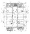
以下、電子部品装着装置1の平面図である図1に基づいて、本発明の実施形態について説明する。先ず、電子部品装着装置1の装置本体2上の前部及び後部には部品供給装置3A、3B、3C、3Dが4つのブロックに分かれて複数並設されている。  Hereinafter, based on FIG. 1 which is a top view of the electroniccomponent mounting apparatus 1, embodiment of this invention is described. First, a plurality ofcomponent supply devices 3A, 3B, 3C, and 3D are arranged in parallel on the front and rear portions of the electroniccomponent mounting device 1 on the devicemain body 2 in four blocks.

前記各部品供給装置3A、3B、3C、3Dは、取付台であるカート台のフィーダベース上に部品供給ユニット5を多数並設したものであり、部品供給側の先端部が基板としてのプリント基板Pの搬送路に臨むように前記装置本体2に連結具を介して着脱可能に配設され、カート台が正規に装置本体2に取り付けられるとカート台に搭載された部品供給ユニット5に電源が供給され、また連結具を解除して把手を引くと下面に設けられたキャスタにより移動できる構成である。  Each of thecomponent supply devices 3A, 3B, 3C, and 3D includes a plurality ofcomponent supply units 5 arranged in parallel on a feeder base of a cart base that is a mounting base, and a printed circuit board having a tip on the component supply side as a substrate. When the cart base is properly attached to the apparatusmain body 2, the power is supplied to thecomponent supply unit 5 mounted on the cart base so as to face the conveyance path of P. When the connector is released and the handle is pulled, it can be moved by a caster provided on the lower surface.

なお、前記フィーダベースから部品供給ユニット5を抜こうとして、電源に接続されるコネクタ同士の接続を解除した場合には、この部品供給ユニット5への供給電源が遮断され、この遮断状態を後述する制御装置70がこれを検出することができ、また逆に前記フィーダベースに部品供給ユニット5を差し込んで取り付けて、前記コネクタ同士を接続すると、この部品供給ユニット5へ電源が供給され、この供給状態を後述する制御装置70がこれを検出することができる。  When the connection between the connectors connected to the power supply is released in order to remove thecomponent supply unit 5 from the feeder base, the power supply to thecomponent supply unit 5 is cut off, and this cut-off state will be described later. Thecontrol device 70 can detect this, and conversely, when thecomponent supply unit 5 is inserted and attached to the feeder base and the connectors are connected to each other, power is supplied to thecomponent supply unit 5 and this supply state This can be detected by thecontrol device 70 described later.

各部品供給装置3A、3B、3C、3Dは、部品供給側の先端部が装着ヘッド6の部品取出し領域である部品吸着取出位置PUに臨むように配設されている。  Each of thecomponent supply devices 3A, 3B, 3C, and 3D is disposed such that the tip on the component supply side faces the component suction / extraction position PU that is the component extraction region of themounting head 6.

そして、手前側の部品供給装置3B、3Dと奥側の部品供給装置3A、3Cとの間には、基板としてのプリント基板Pを搬送する基板搬送装置8を構成する供給コンベア、第1位置決め部、中間コンベア、第2位置決め部及び排出コンベアが設けられている。  Between the front-sidecomponent supply devices 3B and 3D and the rear-sidecomponent supply devices 3A and 3C, a supply conveyor and a first positioning unit constituting thesubstrate transfer device 8 that transfers the printed circuit board P as a substrate An intermediate conveyor, a second positioning portion, and a discharge conveyor are provided.

前記供給コンベアは上流より受けたプリント基板Pを第1位置決め部に搬送し、この各位置決め部で図示しない位置決め機構により位置決めされた基板P上に電子部品を装着した後、中間コンベアに搬送し、この中間コンベアより受けたプリント基板Pを第2位置決め部で位置決め機構により位置決めして電子部品を装着した後、排出コンベアに搬送され、その後下流側装置に搬送される。  The supply conveyor conveys the printed circuit board P received from the upstream to the first positioning unit, and after mounting electronic components on the substrate P positioned by a positioning mechanism (not shown) in each positioning unit, conveys it to the intermediate conveyor, After the printed circuit board P received from the intermediate conveyor is positioned by the positioning mechanism in the second positioning portion and the electronic component is mounted, it is transported to the discharge conveyor and then transported to the downstream device.

Y方向にY軸駆動モータ11によりガイドレール9に沿って移動する各ビーム10にはその長手方向、即ちX方向にX軸駆動モータ13により移動する装着ヘッド6が設けられ、この装着ヘッド6には複数本の部品取出具である吸着ノズル7が設けられる。そして、前記装着ヘッド6には前記吸着ノズル7を上下動させるための上下軸駆動モータ14が搭載され、また鉛直軸周りに回転させるためのθ軸駆動モータ15が搭載されている。従って、装着ヘッド6の吸着ノズル7はX方向及びY方向に移動可能であり、鉛直軸回りに回転可能で、かつ上下動可能となっている。  Eachbeam 10 that moves along theguide rail 9 by the Y-axis drive motor 11 in the Y direction is provided with amounting head 6 that is moved by theX-axis drive motor 13 in the longitudinal direction, that is, in the X direction. Is provided with a suction nozzle 7 which is a plurality of component take-out tools. Themounting head 6 is equipped with a verticalaxis drive motor 14 for moving the suction nozzle 7 up and down, and a θ-axis drive motor 15 for rotating around the vertical axis. Therefore, the suction nozzle 7 of themounting head 6 can move in the X direction and the Y direction, can rotate about the vertical axis, and can move up and down.

4はプリント基板Pの位置認識のための基板認識カメラで、前記装着ヘッド6に固定されて、前記プリント基板Pに付された位置決めマークを撮像する。12は部品認識カメラで、電子部品が吸着ノズル7に対してどれだけ位置ずれして吸着保持されているかXY方向及び回転角度につき、位置認識するために電子部品を撮像する。  Reference numeral 4 denotes a substrate recognition camera for recognizing the position of the printed circuit board P, which is fixed to themounting head 6 and images a positioning mark attached to the printed circuit boardP. Reference numeral 12 denotes a component recognition camera that captures an image of the electronic component in order to recognize the position of the electronic component with respect to the suction nozzle 7 in terms of the XY direction and the rotation angle.

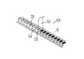
収納テープCXの斜視図である図2に基づいて、収納テープCXについて説明する。この収納テープCXは、キャリアテープCaに所定間隔毎に形成された収納凹部Cb内に電子部品Dを収納して、前記収納凹部Cbを覆うようにカバーテープCcがキャリアテープCa上に接着されている。また、前記キャリアテープCaには所定間隔毎に送り孔Cdが形成されている。  The storage tape CX will be described with reference to FIG. 2 which is a perspective view of the storage tape CX. In this storage tape CX, an electronic component D is stored in storage recesses Cb formed at predetermined intervals on the carrier tape Ca, and a cover tape Cc is bonded onto the carrier tape Ca so as to cover the storage recesses Cb. Yes. The carrier tape Ca has feed holes Cd formed at predetermined intervals.

更に、図3に示すように、カバーテープCcの接着部Ce(収納凹部Cbの左右に、カバーテープCcを接着(融着)固定している部分)は、装填される電子部品のサイズによって、その位置が異なる。即ち、この図3(ア)(図3の左部)及び(イ)(図3の右部)に示す収納テープCXは、ともに8mm幅の紙テープのものであるが、図3(ア)は大部品用の収納テープCXであって、前記収納凹部Cbも大きいので進行方向に沿って塗布された接着部Ceもより外側に位置し、また図3(イ)は小部品用の収納テープCXであって、前記収納凹部Cbも小さいので接着部Ceもより内側に位置する。  Further, as shown in FIG. 3, the adhesive portion Ce of the cover tape Cc (the portion where the cover tape Cc is bonded (fused) and fixed to the left and right of the storage recess Cb) depends on the size of the electronic component to be loaded. Its position is different. That is, the storage tape CX shown in FIGS. 3A (the left part of FIG. 3) and (A) (the right part of FIG. 3) is a paper tape having a width of 8 mm, but FIG. The large component storage tape CX has a large storage recess Cb, so that the adhesive portion Ce applied along the direction of travel is located on the outer side, and FIG. 3 (a) shows the small component storage tape CX. And since the said storage recessed part Cb is also small, the adhesion part Ce is also located inside.

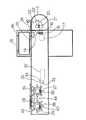
次に、前記部品供給ユニット5の概略側面図である図4及び前記部品供給ユニット5の概略平面図である図5に基づいて、フィーダベース上に並設される部品供給ユニット5の構成について簡単に説明する。先ず、部品供給ユニット5は、回転自在に装着した収納テープリールに巻回した状態の収納テープCXを案内通路を介して導入するテープ導入機構を備えている。  Next, based on FIG. 4 which is a schematic side view of thecomponent supply unit 5 and FIG. 5 which is a schematic plan view of thecomponent supply unit 5, the configuration of thecomponent supply unit 5 arranged in parallel on the feeder base will be simply described. Explained. First, thecomponent supply unit 5 includes a tape introduction mechanism that introduces the storage tape CX wound around a storage tape reel that is rotatably mounted through a guide passage.

このテープ導入機構は、テープ導入駆動源であってその出力軸16にギア18を備えた導入モータであるDCモータ17と、前記ギア18と噛み合うギア19が設けられた回転軸20の中間部に設けられたウォームギア21と噛み合うウォームホィール22を備えると共にテープ押さえ部材24に上方から押さえられた収納テープCXに形成した送り孔Cbにその外周部に形成されたテープ送り歯が噛み合ってこの収納テープCXを送る第1スプロケット23とから構成される。25は第1検出センサで、前記部品供給ユニット5内に導入された前記収納テープCXを検出するセンサである。  This tape introduction mechanism is a tape introduction drive source that is provided at the intermediate portion between aDC motor 17 that is an introduction motor provided with a gear 18 on itsoutput shaft 16 and arotary shaft 20 provided with agear 19 that meshes with the gear 18. Aworm wheel 22 that meshes with the providedworm gear 21 and a feed hole Cb formed on the storage tape CX pressed by thetape pressing member 24 from above is engaged with a tape feed tooth formed on the outer peripheral portion of the storage tape CX. Thefirst sprocket 23 is configured to transmit. Afirst detection sensor 25 is a sensor for detecting the storage tape CX introduced into thecomponent supply unit 5.

27は第2スプロケットで、前記部品供給ユニット5に着脱可能なテープ処理ユニット28への収納テープCXの供給動作を担う。29は第3スプロケットで、前記テープ処理ユニット28のカッター30により前記収納テープCXのカバーテープCcを切り開くように前記収納テープCXを前進移動させるためのものである。  Reference numeral 27 denotes a second sprocket, which is responsible for supplying the storage tape CX to thetape processing unit 28 that can be attached to and detached from thecomponent supply unit 5.Reference numeral 29 denotes a third sprocket for moving the storage tape CX forward so that the cover tape Cc of the storage tape CX is cut open by thecutter 30 of thetape processing unit 28.

32はサーボモータで、その出力軸33に設けられたプーリと回転軸34に設けられたプーリとの間にはベルト35が張架され、前記サーボモータ32が正転すると、出力軸33及びベルト35を介して回転軸34が回転する。  Reference numeral 32 denotes a servo motor. Abelt 35 is stretched between a pulley provided on theoutput shaft 33 and a pulley provided on therotary shaft 34. When theservo motor 32 rotates forward, theoutput shaft 33 and the belt The rotatingshaft 34 rotates via 35.

従って、前記回転軸34が間欠回転すると、この回転軸34の中間部に設けられた各ウォームギア37、38と噛み合うウォームホィール39、40を備えた前記第2スプロケット27、第3スプロケット29がそれぞれ間欠回転することとなる。即ち、サプレッサ43により上方から押さえられた収納テープCXに形成した送り孔Cbに第2スプロケット27、第3スプロケット29の外周部に形成されたテープ送り歯が噛み合って、前記回転軸34が回転すると、第2スプロケット27及び第3スプロケット29が回転することとなり、収納テープCXを間欠的に送ることができる。  Therefore, when the rotatingshaft 34 rotates intermittently, thesecond sprocket 27 and thethird sprocket 29 provided with theworm wheels 39 and 40 meshing with the worm gears 37 and 38 provided in the intermediate portion of therotating shaft 34 are intermittently respectively provided. It will rotate. That is, when the feed shaft Cb formed in the outer peripheral portion of thesecond sprocket 27 and thethird sprocket 29 meshes with the feed hole Cb formed in the storage tape CX pressed from above by thesuppressor 43, the rotatingshaft 34 rotates. Thesecond sprocket 27 and thethird sprocket 29 will rotate, and the storage tape CX can be sent intermittently.

44は第2検出センサで、導入された前記収納テープCXを検出するセンサである。そして、前記部品供給ユニット5への収納テープCXの装填時に、前記第1スプロケット23から第2スプロケット27の各テープ送り歯への収納テープCXの送り孔Cdの嵌合時(速度差による乗り継ぎ)の遊びロス、即ち直ぐには嵌らず滑りながら、やがて嵌合することに配慮し、収納テープCX先端位置の把握を確実に行うため、第2スプロケット27と第3スプロケット29との間に、第2検出センサ44を配置して、収納テープCXの先端検出をした際に減速するようにしてから停止するように制御する。  Asecond detection sensor 44 is a sensor for detecting the introduced storage tape CX. When the storage tape CX is loaded into thecomponent supply unit 5, when the feed hole Cd of the storage tape CX is fitted from thefirst sprocket 23 to each tape feed dog of the second sprocket 27 (transfer due to speed difference). In order to ascertain the position of the end of the storage tape CX with certainty, the play loss of thesecond sprocket 27 and thethird sprocket 29 is considered. Thesecond detection sensor 44 is arranged to control so as to decelerate and stop when the leading end of the storage tape CX is detected.

なお、第1スプロケット23と第2スプロケット27との間隔は大きいため、収納テープCXの各送り孔Cdの累積されたピッチ誤差により両スプロケット23、27のテープ送り歯の嵌合動作に影響が出るため、第1スプロケット23の回転数は、第2スプロケット27の回転数よりやや遅い低速回転とする。更に、収納テープCXの送り位置精度に影響の出る送り孔Cdの変形を少なくするため、第1スプロケット23のテープ送り歯形状は丸歯状にした形状を採用して、送り孔Cdを初期状態のまま変形させずに、前方の第2スプロケット27、第3スプロケット29へ運べるようにした。  In addition, since the space | interval of the1st sprocket 23 and the2nd sprocket 27 is large, the fitting operation | movement of the tape feed dog of both thesprockets 23 and 27 will be influenced by the accumulated pitch error of each feed hole Cd of the storage tape CX. Therefore, the rotation speed of thefirst sprocket 23 is set to a low-speed rotation that is slightly slower than the rotation speed of thesecond sprocket 27. Further, in order to reduce the deformation of the feed hole Cd that affects the feed position accuracy of the storage tape CX, the tape feed tooth shape of thefirst sprocket 23 is a round tooth shape, and the feed hole Cd is in the initial state. Thesecond sprocket 27 and thethird sprocket 29 can be carried forward without being deformed.

また、第2スプロケット27と第3スプロケット29は極力近くに配置し、累積ピッチ誤差の影響が出ないスパンとすると共に、テープ処理シーケンスで必要な加減速コントロール、速度制御、トルク制御が担えるよう前述したようにサーボモータ32を採用すると共に同一駆動源による動作とした。  Further, thesecond sprocket 27 and thethird sprocket 29 are arranged as close as possible so that the span is not affected by the accumulated pitch error, and the acceleration / deceleration control, speed control, and torque control required in the tape processing sequence can be performed. As described above, theservo motor 32 is employed and the operation is performed by the same drive source.

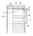
次に、小部品用の後述する型式「W8S」の前記テープ処理ユニット28について、図6乃至図14に基づいて説明する。先ず、部品供給ユニット5には収納テープCXを搬送する案内シュート50がユニット本体5Aに固定ボルト26により固定されており、この案内シュート50上を摺動して搬送される収納テープCXをこの案内シュート50に上方から常時押圧して収納テープCXの送り時に収納テープCXが上下に動かないようにし、第2スプロケット27及び第3スプロケット29のテープ送り歯から収納テープCXの送り孔Cdが抜けて外れないように前記サプレッサ43が作用する。  Next, thetape processing unit 28 of the type “W8S” to be described later for small parts will be described with reference to FIGS. First, aguide chute 50 for transporting the storage tape CX is fixed to the unitmain body 5A by the fixingbolt 26 in thecomponent supply unit 5, and the storage tape CX that is transported by sliding on theguide chute 50 is guided by this guide. The storage tape CX is constantly pressed against thechute 50 so that the storage tape CX does not move up and down when the storage tape CX is fed. Thesuppressor 43 acts so as not to come off.

なお、前記固定ボルト26による前記案内シュート50のユニット本体5Aへの固定は、前記テープ処理ユニット28の上面に開設された貫通孔41を介してか、又は前記サプレッサ43に開設された貫通孔42及び前記貫通孔41を介して工具を挿入して前記固定ボルト26の頭部を捻じ込むことにより行える。  Note that theguide chute 50 is fixed to the unitmain body 5A by the fixingbolt 26 through a throughhole 41 provided in the upper surface of thetape processing unit 28 or through a throughhole 42 provided in thesuppressor 43. Further, it can be performed by inserting a tool through the throughhole 41 and screwing the head of the fixingbolt 26.

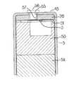
ここで、前記サプレッサ43について詳述すると、このサプレッサ43は断面が概ねコ字形状を呈しており、その上面43Aには取付用開口52が開設され、この取付用開口52内に前記テープ処理ユニット28上面の一部である凸部28Aが下方から嵌り込んだ状態で取付けられる。  Here, thesuppressor 43 will be described in detail. Thesuppressor 43 has a substantially U-shaped cross section, and anattachment opening 52 is formed in theupper surface 43A, and the tape processing unit is provided in theattachment opening 52. 28 is attached in a state in which aconvex portion 28A which is a part of the upper surface is fitted from below.

この場合、取付用開口52を避けた前記サプレッサ43の上面43Aには位置決め用開口54及び取付孔55が2つずつ開設され、前記テープ処理ユニット28の上面に形成された各位置決め用凸部56を前記サプレッサ43の上面の各位置決め用開口54に嵌合して位置決めした状態で、前記位置決め用凸部56の近くに開設された各ビス孔57と各取付孔55が合致されて各固定ビス58が各取付孔55を貫通した状態で各ビス孔57に螺合して、前記サプレッサ43に前記テープ処理ユニット28が着脱可能に取付けられる(図7、図8及び図14参照)。  In this case, two positioningopenings 54 and two mountingholes 55 are provided on theupper surface 43A of thesuppressor 43 that avoids the mountingopening 52, and each positioningprojection 56 formed on the upper surface of thetape processing unit 28. Are fitted in thepositioning openings 54 on the upper surface of thesuppressor 43 and positioned so that the screw holes 57 and the mountingholes 55 opened near the positioningconvex portions 56 are matched with each other. Thetape processing unit 28 is detachably attached to the suppressor 43 (see FIGS. 7, 8, and 14) by screwing 58 into the screw holes 57 in a state of passing through the attachment holes 55.

また、前記サプレッサ43の両側面43B、43C間には、支持ピン60が両側面43B、43Cを連結するように設けられ、この支持ピン60と前記案内シュート50の水平面50Aに形成された収納凹部50Bとの間にはスプリング61が配設され、このスプリング61の付勢力により前記案内シュート50上の収納テープCXをこの案内シュート50に上方から常時押圧して、前記第2スプロケット27及び第3スプロケット29のテープ送り歯から収納テープCXの送り孔Cdが抜けないようにしている。  Asupport pin 60 is provided between both side surfaces 43B and 43C of thesuppressor 43 so as to connect the both side surfaces 43B and 43C. A storage recess formed in thehorizontal surface 50A of thesupport pin 60 and theguide chute 50 is provided. Aspring 61 is disposed between thesecond sprocket 27 and thethird sprocket 27, and the storage tape CX on theguide chute 50 is always pressed against theguide chute 50 from above by the urging force of thespring 61. The feed hole Cd of the storage tape CX is prevented from coming off from the tape feed dog of thesprocket 29.

なお、前記固定ビス58の前記ビス孔57への螺合を解除して、この固定ビス58を取付孔55から抜いて、前記スプリング61の付勢力に抗して前記サプレッサ43を上方へ押し上げると、前記取付用開口52から前記テープ処理ユニット28上面の凸部が外れることとなり、前記サプレッサ43の前方から前記テープ処理ユニット28が引き出しながら取り外すことができる。  When the screw of the fixingscrew 58 into thescrew hole 57 is released, the fixingscrew 58 is removed from the mountinghole 55, and thesuppressor 43 is pushed upward against the urging force of thespring 61. The convex portion on the upper surface of thetape processing unit 28 is removed from the mountingopening 52, and thetape processing unit 28 can be removed while being pulled out from the front of thesuppressor 43.

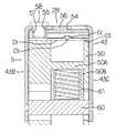
このため、小部品用の型式「W8S」に代えて、図15に示す型式「W8LL」のテープ処理ユニット28を前記サプレッサ43に固定することができる。即ち、前記サプレッサ43の前方から型式「W8LL」のテープ処理ユニット28の下方に挿入し、前記テープ処理ユニット28の上面に形成された各位置決め用凸部56を前記サプレッサ43の上面の各位置決め用開口54に嵌合して位置決めした状態で、前記位置決め用凸部56の近くに開設された各ビス孔57と各取付孔55が合致されて各固定ビス58が各取付孔55を貫通した状態で各ビス孔57に螺合して、前記サプレッサ43にこの型式「W8LL」のテープ処理ユニット28を取付けることができる。  Therefore, thetape processing unit 28 of the model “W8LL” shown in FIG. 15 can be fixed to thesuppressor 43 instead of the model “W8S” for small parts. That is, from the front side of thesuppressor 43, it is inserted below thetape processing unit 28 of the type “W8LL”, and each positioningconvex portion 56 formed on the upper surface of thetape processing unit 28 is used for each positioning on the upper surface of thesuppressor 43. A state in which eachscrew hole 57 and each mountinghole 55 which are opened near the positioningconvex portion 56 are matched with each other and each fixingscrew 58 passes through each mountinghole 55 in a state where the positioning is performed by fitting in theopening 54. Thus, it is possible to attach thetape processing unit 28 of this type “W8LL” to thesuppressor 43 by screwing into eachscrew hole 57.

従って、部品供給ユニット5に異なる種類のテープ処理ユニット28を着脱可能にしたから、部品供給ユニット5を共用することができるので、管理が容易で管理コストの低減を図れると共に管理保管スペースの削減を図ることができる。  Accordingly, since the different types oftape processing units 28 can be attached to and detached from thecomponent supply unit 5, thecomponent supply unit 5 can be shared. Therefore, management is easy, management costs can be reduced, and management storage space can be reduced. You can plan.

なお、図3(ア)の大部品用の収納テープCXは収納凹部Cbも大きいので進行方向に沿って塗布された接着部Ceもより外側に位置しており、図17及び図18に示すように、小部品用の型式「W8S」のテープ処理ユニット28に比べ、大部品用の「W8LL」のテープ処理ユニット28は、カバーテープCcの開き量を多くしなければ電子部品Dと吸着ノズル7で取出すことができないので、開き角度も大きくなるような案内面64Aとなっている。  In addition, since the storage tape CX for large components in FIG. 3A has a large storage recess Cb, the adhesive portion Ce applied along the traveling direction is located on the outer side, as shown in FIGS. 17 and 18. In addition, compared with thetape processing unit 28 of the type “W8S” for small parts, thetape processing unit 28 of the “W8LL” for large parts requires the electronic component D and the suction nozzle 7 to be opened unless the opening amount of the cover tape Cc is increased. Therefore, theguide surface 64A has a large opening angle.

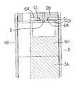
また、前記テープ処理ユニット28には開口63が開設され、供給された収納テープCXのカバーテープCcを進行方向に沿って、その進行に伴って順次切り開くカッター30を前記開口63を介して見ることができる(図6、図9参照)。そして、この収納テープCXの進行に伴ってカバーテープCcは順次切り開かれるが(図9及び図10)、切り開かれたらその開口端部が最高高さ地点となるように上方へ押し開くように案内する案内面64が進行方向に向かって左右にそれぞれ形成されている(図11参照)。  Further, anopening 63 is opened in thetape processing unit 28, and thecutter 30 that sequentially cuts the cover tape Cc of the supplied storage tape CX along the traveling direction along the traveling direction is viewed through theopening 63. (See FIGS. 6 and 9). As the storage tape CX advances, the cover tape Cc is sequentially cut and opened (FIGS. 9 and 10). When the storage tape CX is opened, the cover tape Cc is guided to push upward so that the opening end is at the maximum height. Guide surfaces 64 are formed on the left and right in the direction of travel (see FIG. 11).

更に、前記テープ処理ユニット28には電子部品Dより大きな平面積を有する部品取出開口65が開設され(図6及び図12参照)、前記案内面64に沿って収納凹部Cb内に収納された電子部品Dの幅よりも広く開かれた部品吸着取出位置PUにおいて、装着ヘッド6に設けられた吸着ノズル7が前記部品取出開口65を介して前記収納凹部Cb内の電子部品Dを吸着して取出すことができる。  Furthermore, thetape processing unit 28 is provided with acomponent extraction opening 65 having a larger area than that of the electronic component D (see FIGS. 6 and 12), and the electronic component stored in the storage recess Cb along theguide surface 64. In a component suction / extraction position PU that is wider than the width of the component D, the suction nozzle 7 provided in the mountinghead 6 sucks and takes out the electronic component D in the storage recess Cb through thecomponent extraction opening 65. be able to.

但し、この前記部品取出開口65が形成された部位には、前記各案内面64は形成できないが、前記部品取出開口65より進行方向の先には再び左右に案内面64が形成され(図6参照)、やがてこの案内面64は形成されない(図12乃至図14)。  However, the guide surfaces 64 cannot be formed at the part where thecomponent extraction opening 65 is formed, but the guide surfaces 64 are again formed on the left and right sides in the traveling direction beyond the component extraction opening 65 (FIG. 6). In the meantime, theguide surface 64 will not be formed (FIGS. 12 to 14).

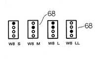
なお、前記テープ処理ユニット28には、種別判別用の情報識別部66が設けられ、この情報識別部66は電子部品装着装置1の作業者識別用の情報識別部67と、電子部品装着装置1の情報識別部68とから構成される。作業者識別用の情報識別部67は作業者が目視して前記テープ処理ユニット28の種類が識別できるように、その型式、例えば「W8S」などが刻印されている。また、電子部品装着装置1の情報識別部68は、図16に示すように、4個のドットを用いた二値化情報(ビット)で、即ち黒丸の印字が0〜15までの前記テープ処理ユニット28の種別(種類)が識別できるように、その型式、例えば図16の最左部は「W8S」、その右隣は「W8M」、その右隣は「W8L」、最右部は「W8LL」という種類がわかるように付されている。  Thetape processing unit 28 is provided with aninformation identifying unit 66 for type discrimination. Theinformation identifying unit 66 includes aninformation identifying unit 67 for identifying an operator of the electroniccomponent mounting apparatus 1 and the electroniccomponent mounting apparatus 1. Theinformation identification unit 68. Theinformation identifying section 67 for identifying the worker is engraved with its type, for example, “W8S” so that the operator can visually identify the type of thetape processing unit 28. In addition, as shown in FIG. 16, theinformation identification unit 68 of the electroniccomponent mounting apparatus 1 is the binarized information (bits) using four dots, that is, the tape processing in which black circles are printed from 0 to 15. The type (type) of theunit 28 can be identified, for example, “W8S” in the leftmost part of FIG. 16, “W8M” in the right side, “W8L” in the right side, and “W8LL” in the right side. "So that the type of"

なお、前述したように、前記情報識別部68は4個のドットを用いた二値化情報(ビット)であったが、直接文字認識できるものや、バーコード情報(一次元又は二次元)を貼付したり、或いはメモリタグ、ミューチップなどの記録媒体を埋め込んでもよい。これらの媒体を使用する場合は、前記テープ処理ユニット28の型式情報の他に、ユニークな管理コードも情報に加えて、個々の管理も可能にすることができる。  As described above, theinformation identification unit 68 is binarized information (bits) using four dots. However, information that can be directly recognized or barcode information (one-dimensional or two-dimensional) is used. It may be attached or a recording medium such as a memory tag or a mu chip may be embedded. When these media are used, in addition to the type information of thetape processing unit 28, individual management can be performed in addition to the unique management code and information.

なお、前記テープ処理ユニット28の型式と対象電子部品の関係表(記憶装置89に格納されている。)である図19に示すように、型式「W8S」は、対象電子部品の範囲が「0402〜0603」で、この電子部品のX方向の寸法が0.40〜0.60mmで、Y方向の寸法が0.20〜0.30mmであり、型式「W8M」は、対象電子部品の範囲が「1005〜1608」で、この電子部品のX方向の寸法が0.61〜1.60mmで、Y方向の寸法が0.31〜3.40mmであり、型式「W8L」は、対象電子部品の範囲が「1608〜2012」で、この電子部品のX方向の寸法が1.61〜2.10mmで、Y方向の寸法が0.31〜3.40mmであり、型式「W8LL」は、対象電子部品の範囲が「2012〜3225」で、この電子部品のX方向の寸法が2.11〜4.30mmで、Y方向の寸法が0.31〜3.40mmである。即ち、例えば型式「W8S」は、電子部品のX方向の寸法が0.40〜0.60mmの範囲内で、Y方向の寸法が0.20〜0.30mmの範囲内の電子部品を扱うことができることを意味する。  As shown in FIG. 19 which is a relationship table between the model of thetape processing unit 28 and the target electronic component (stored in the storage device 89), the range of the target electronic component is “0402” in the model “W8S”. ˜0603 ”, the dimension in the X direction of this electronic component is 0.40 to 0.60 mm, the dimension in the Y direction is 0.20 to 0.30 mm, and the model“ W8M ”has a range of the target electronic component. “1005 to 1608”, the dimension of the electronic component in the X direction is 0.61 to 1.60 mm, the dimension in the Y direction is 0.31 to 3.40 mm, and the model “W8L” The range is “1608 to 2012”, the dimension in the X direction of this electronic component is 1.61 to 2.10 mm, the dimension in the Y direction is 0.31 to 3.40 mm, and the model “W8LL” The range of parts is “2012-3225 In, the X dimension of the electronic component 2.11~4.30Mm, Y direction dimension of 0.31~3.40Mm. That is, for example, the model “W8S” handles electronic components whose X-direction dimensions are in the range of 0.40 to 0.60 mm and whose Y-direction dimensions are in the range of 0.20 to 0.30 mm. Means you can.

次に、図20の電子部品装着装置1の制御ブロック図について説明すると、前記電子部品装着装置1には、本装着装置1を統括制御する制御手段、判定手段、実行手段、命令手段等としての制御装置70と、該制御装置70にバスラインを介して接続される記憶装置71が備えられている。そして、制御装置70は前記記憶装置71に記憶されたデータに基づいて、電子部品装着装置1の部品装着動作に係る動作を統括制御する。  Next, the control block diagram of the electroniccomponent mounting apparatus 1 in FIG. 20 will be described. The electroniccomponent mounting apparatus 1 includes control means, determination means, execution means, instruction means, etc. that control theoverall mounting apparatus 1. Acontrol device 70 and astorage device 71 connected to thecontrol device 70 via a bus line are provided. Based on the data stored in thestorage device 71, thecontrol device 70 comprehensively controls operations related to the component mounting operation of the electroniccomponent mounting device 1.

即ち、制御装置70は、インターフェース74及び駆動回路77を介して前記Y軸駆動モータ11、X軸駆動モータ13、上下軸駆動モータ14及び前記θ軸駆動モータ15等の駆動を制御すると共に各部品供給ユニット5を制御する。この図20では、説明の便宜上、複数あるものでも、例えば装着ヘッド6、部品供給ユニット5などは1つとして省略してある。  That is, thecontrol device 70 controls the drive of the Y-axis drive motor 11, theX-axis drive motor 13, the verticalaxis drive motor 14, the θ-axis drive motor 15 and the like through theinterface 74 and thedrive circuit 77, and each component. Thesupply unit 5 is controlled. In FIG. 20, for convenience of explanation, even though there are a plurality of them, for example, the mountinghead 6 and thecomponent supply unit 5 are omitted as one.

前記記憶装置71には、部品装着に係るプリント基板Pの種類毎に装着データ(図24参照)が記憶されており、その装着順序毎(ステップ番号毎)に、プリント基板P内でのX方向(Xで示す)、Y方向(Yで示す)及び角度(Zで示す)情報や、各部品供給ユニット5の配置番号情報等が格納されている。  Thestorage device 71 stores mounting data (see FIG. 24) for each type of printed circuit board P related to component mounting, and the X direction in the printed circuit board P for each mounting order (for each step number). (Indicated by X), Y direction (indicated by Y) and angle (indicated by Z) information, arrangement number information of eachcomponent supply unit 5 and the like are stored.

また前記記憶装置71には、各プリント基板Pの種類毎に前記各部品供給ユニット5の配置番号(レーン番号)に対応した各電子部品の種類(部品ID)の情報、即ち部品配置情報(図25参照)が格納されており、この部品配置情報は前記カート台上のどの位置にどの部品供給ユニット5を搭載するかに係るデータである。更にはこの部品ID毎に電子部品のX方向及びY方向の寸法等の電子部品の特徴等に関する部品ライブラリデータ(図26参照)が格納されている。  In thestorage device 71, information on the type (component ID) of each electronic component corresponding to the arrangement number (lane number) of eachcomponent supply unit 5 for each type of printed circuit board P, that is, component arrangement information (see FIG. 25) is stored, and this component arrangement information is data relating to whichcomponent supply unit 5 is mounted at which position on the cart table. Furthermore, component library data (see FIG. 26) relating to the characteristics of the electronic components such as the X-direction and Y-direction dimensions of the electronic components is stored for each component ID.

73はインターフェース74を介して前記制御装置70に接続される認識処理装置で、前記部品認識カメラ12により撮像して取込まれた画像や前記基板認識カメラ4により撮像して取り込まれた画像の認識処理が該認識処理装置73にて行われ、制御装置70に処理結果が送出される。即ち、制御装置70は、部品認識カメラ12に撮像された画像や前記基板認識カメラ4に撮像された画像を認識処理(位置ずれ量の算出など)するように指示を認識処理装置73に出力すると共に、認識処理結果を認識処理装置73から受取るものである。  Arecognition processing device 73 is connected to thecontrol device 70 via aninterface 74 and recognizes an image captured by thecomponent recognition camera 12 and an image captured by thesubstrate recognition camera 4 and captured. Processing is performed by therecognition processing device 73, and the processing result is sent to thecontrol device 70. That is, thecontrol device 70 outputs an instruction to therecognition processing device 73 so as to perform recognition processing (calculation of misalignment amount, etc.) on the image captured by thecomponent recognition camera 12 and the image captured by theboard recognition camera 4. At the same time, the recognition processing result is received from therecognition processing device 73.

75は部品画像や各種データ設定のための画面などを表示するモニタで、このモニタ75には入力手段としての種々のタッチパネルスイッチ76が設けられ、作業者がタッチパネルスイッチ76を操作することにより、種々の設定を行うことができる。  Amonitor 75 displays a part image, a screen for setting various data, and the like. Themonitor 75 is provided with various touch panel switches 76 as input means. Can be set.

また、前記導入モータ17及び前記サーボモータ32により収納テープCXを導入し間欠送りする部品供給ユニット5は、制御装置79と記憶装置80とを備えている。82はそれぞれインターフェース81を介して前記制御装置79に接続される駆動回路で、制御装置79はDCモータ17及びサーボモータ32を駆動回路82を介して制御する。この部品供給ユニット5に設けられる制御装置79は、インターフェース81及び74を介して電子部品装着装置1に設けられる制御装置70に接続される。  Thecomponent supply unit 5 that introduces the storage tape CX by theintroduction motor 17 and theservo motor 32 and intermittently feeds it includes acontrol device 79 and astorage device 80.Reference numeral 82 denotes a drive circuit connected to thecontrol device 79 via aninterface 81, and thecontrol device 79 controls theDC motor 17 and theservo motor 32 via thedrive circuit 82. Acontrol device 79 provided in thecomponent supply unit 5 is connected to acontrol device 70 provided in the electroniccomponent mounting device 1 viainterfaces 81 and 74.

なお、図4、図5に示すように、前記部品供給ユニット5の杷手46の上面には操作パネル78が設けられ、この操作パネル78には部品供給ユニット5の配置番号(レーン番号)を選択するためのレーン番号選択ボタン78Aと、このレーン番号選択ボタン78Aの左部押圧毎に1ずつレーン番号を増加させて表示すると共に右部押圧毎に1ずつレーン番号を減少させて表示する表示部78Bと、送りボタン78Cと戻りボタン78D、ローディングボタン78Eとが設けられている(図21参照)。  As shown in FIGS. 4 and 5, anoperation panel 78 is provided on the upper surface of thehandle 46 of thecomponent supply unit 5. Theoperation panel 78 has an arrangement number (lane number) of thecomponent supply unit 5. A lanenumber selection button 78A for selection, and a display that increases the lane number by 1 each time the left portion of the lanenumber selection button 78A is pressed and decreases the lane number by 1 each time the right portion is pressed. Asection 78B, afeed button 78C, a return button 78D, and a loading button 78E are provided (see FIG. 21).

従って、前記部品供給ユニット5を前述したフィーダベース上から取り外したり、取り付けたりする際に、表示部78Bを見ながら部品供給ユニット5の配置番号(レーン番号)をレーン番号選択ボタン78Aの押圧操作に基づいて選択(変更)することができる。その選択された部品供給ユニット5の配置番号(レーン番号)は記憶装置89、70に書換え記憶されることとなる。  Therefore, when thecomponent supply unit 5 is removed from or attached to the feeder base described above, the arrangement number (lane number) of thecomponent supply unit 5 is pressed by the lanenumber selection button 78A while viewing thedisplay unit 78B. It can be selected (changed) based on this. The arrangement number (lane number) of the selectedcomponent supply unit 5 is rewritten and stored in thestorage devices 89 and 70.

次に、部品供給ユニット5に収納テープCXを装填する動作について、説明する。先ず、テープ押さえ部材24を外して収納テープCX先端部を前記案内通路上に載置して、第1スプロケット23のテープ送り歯を収納テープCXの送り孔Cbに嵌合させた後に、テープ押さえ部材24をセットする。  Next, an operation for loading the storage tape CX into thecomponent supply unit 5 will be described. First, thetape pressing member 24 is removed, the tip of the storage tape CX is placed on the guide passage, the tape feed dog of thefirst sprocket 23 is fitted into the feed hole Cb of the storage tape CX, and then the tape press Themember 24 is set.

そして、作業者は操作パネル78のローディングボタン78Eを押圧操作すると、制御装置79は前記第1検出センサ25及び第2検出センサ44が収納テープCXを検出していなければ、DCモータ17をタイマー45による所定時間だけ駆動させるように制御し、収納テープCXは第1スプロケット23の回転により部品供給ユニット5内奥方へ順次挿入される。  When the operator presses the loading button 78E of theoperation panel 78, thecontrol device 79 sets theDC motor 17 to thetimer 45 unless thefirst detection sensor 25 and thesecond detection sensor 44 detect the storage tape CX. The storage tape CX is sequentially inserted into the interior of thecomponent supply unit 5 by the rotation of thefirst sprocket 23.

そして、この挿入に伴い、タイマー45による所定時間を計時したら前記DCモータ17の駆動を停止し、第1検出センサ25が収納テープCXの先端を検出したら、前記DCモータ17及びサーボモータ32の駆動を開始させて、第1スプロケット23、第2スプロケット27及び第3スプロケット29により収納テープCXが前方へ移動させられる。  Then, along with this insertion, the driving of theDC motor 17 is stopped when a predetermined time is measured by thetimer 45, and when thefirst detection sensor 25 detects the leading end of the storage tape CX, the driving of theDC motor 17 and theservo motor 32 is performed. The storage tape CX is moved forward by thefirst sprocket 23, thesecond sprocket 27, and thethird sprocket 29.

そして、予め設定された送り量に従い、移動動作を継続し、この移動中に第2検出センサ44が収納テープCXの先端を検出したら、制御装置79はDCモータ17の駆動を停止させ、サーボモータ32を強制的に減速させながら停止させる。なお、この場合、前述の予め設定された送り量がなされたにもかかわらず、第2検出センサ44が収納テープCX先端を検出できない場合には、制御装置79はDCモータ17及びサーボモータ32を異常停止させるように制御する。  Then, the moving operation is continued according to the preset feed amount, and when thesecond detection sensor 44 detects the leading end of the storage tape CX during the movement, thecontrol device 79 stops the driving of theDC motor 17 and the servo motor. 32 is forcibly decelerated and stopped. In this case, if thesecond detection sensor 44 cannot detect the leading end of the storage tape CX despite the above-described preset feed amount, thecontrol device 79 causes theDC motor 17 and theservo motor 32 to be connected. Control to stop abnormally.

続いて、サーボモータ32によって前述した減速してから停止する際の収納テープCXのオーバーラン量を鑑みて、最小ピッチ送りによる逆転動作を収納テープCXの先端が第2検出センサ44が検知しなくなるまで繰り返し、収納テープCXの先端位置を確定する。即ち、サーボモータ32の最少ピッチの逆転動作及び停止動作を繰り返すことにより収納テープCXの先端位置を確定する。  Subsequently, in consideration of the overrun amount of the storage tape CX when theservo motor 32 decelerates and stops as described above, thesecond detection sensor 44 does not detect the reverse rotation operation by the minimum pitch feed at the front end of the storage tape CX. Repeat until the end position of the storage tape CX is determined. That is, the tip position of the storage tape CX is determined by repeating the reverse rotation operation and the stop operation of theservo motor 32 with the minimum pitch.

なお、第1スプロケット23はワンウェイクラッチを備えていて逆転はしないが、戻し量が微小であること、第1スプロケット23の歯高が低いことにより第2スプロケット27の送り歯に嵌合した収納テープCXはサーボモータ32の推力で後方へ滑り出される。  Thefirst sprocket 23 is provided with a one-way clutch and does not rotate in reverse, but the return tape is small and the storage tape fitted to the feed teeth of thesecond sprocket 27 due to the low tooth height of thefirst sprocket 23. CX is slid backward by the thrust of theservo motor 32.

そして、所定量の1回送り動作で収納テープCXの先端部をカッター30の刃の直前位置まで高速で送りこむようにサーボモータ32の駆動を制御する。即ち、収納テープCXの先端位置の確定により、カッター30の刃の直前位置まで設計寸法に従い、収納テープCXを高速で送り込む。  Then, the drive of theservo motor 32 is controlled so that the tip of the storage tape CX is fed at a high speed to the position immediately before the blade of thecutter 30 by a predetermined amount of one-time feeding operation. That is, by determining the tip position of the storage tape CX, the storage tape CX is fed at a high speed according to the design dimensions up to the position immediately before the blade of thecutter 30.

その後、カバーテープCcのカッタ−30による切り開きゾーンへ収納テープCXを挿入し、カバーテープCcの切り開きを行う。この場合、カバーテープCcをキャリアテープCaから剥離するのではなく、進行方向に対して左右方向に切り開くように上方へ向けて開くため、超低速度又は超低加速度で所定量の1回送りを行う。  Thereafter, the storage tape CX is inserted into the slitting zone of the cover tape Cc by thecutter 30 to cut the cover tape Cc. In this case, the cover tape Cc is not peeled off from the carrier tape Ca, but is opened upward so as to be cut open in the left-right direction with respect to the traveling direction. Do.

そして、収納テープCXの先端部の収納凹部Cbの位置を、部品吸着取出位置PUに頭出しするためのピッチ送り動作を所定回数行う。この場合、先の収納テープCXの先端位置確定の位置からの累計送り量(第2スプロケット27のテープ送り歯の送り孔Cdへの嵌合によるサーボモータ32の駆動管理量)に従い、送りピッチに従っての収納凹部Cbの位置を部品吸着取出位置PUに運び込むための所定送り動作を実施する。  Then, a pitch feeding operation for cueing the position of the storage recess Cb at the tip of the storage tape CX to the component suction / extraction position PU is performed a predetermined number of times. In this case, according to the feed pitch according to the cumulative feed amount from the position where the tip position of the previous storage tape CX is determined (the drive management amount of theservo motor 32 by fitting the tape feed dog of thesecond sprocket 27 to the feed hole Cd). A predetermined feeding operation for carrying the position of the storage recess Cb to the component suction / extraction position PU is performed.

この収納凹部Cbの位置の自動合わせは、収納テープCX先端の送り孔Cd基準に従った切断位置を元に、テーピング規格に則った収納凹部Cbの位置関係より、送り量をコントロールして行う。  The automatic positioning of the storage recess Cb is performed by controlling the feed amount based on the positional relationship of the storage recess Cb in accordance with the taping standard based on the cutting position according to the feed hole Cd standard at the tip of the storage tape CX.

次に、前記テープ処理ユニット28の種別の自動照合に係る図22のフローチャート及び前記テープ処理ユニット28の種別の確認の要否判定に係る図23のフローチャートに基づいて、以下説明する。なお、ここで、フィーダとは、部品供給ユニット5を指すものとする。  Next, description will be made below based on the flowchart of FIG. 22 relating to the automatic verification of the type of thetape processing unit 28 and the flowchart of FIG. 23 relating to the necessity determination of the type of thetape processing unit 28. Here, the feeder refers to thecomponent supply unit 5.

先ず、図22のステップS01において、前記テープ処理ユニット28の種別の確認の要否判定が制御装置70によりなされる。この要否判定について、図23に基づき説明すると、初めに前述したような収納テープCXの自動ローディング後の最初の電子部品Dの取出しか否かが制御装置70により判定される(ステップS20)。  First, in step S01 of FIG. 22, thecontroller 70 determines whether or not the type of thetape processing unit 28 needs to be confirmed. The necessity determination will be described with reference to FIG. 23. First, thecontrol device 70 determines whether or not the first electronic component D after automatic loading of the storage tape CX as described above is taken out (step S20).

この場合、前述したような収納テープCXの自動ローディング(前記部品供給ユニット5への収納テープCXの搭載)後の最初の電子部品Dの取出しと判定されると、前記テープ処理ユニット28の記憶装置80の内容をセット(「ON」)するように、制御装置70は制御装置79を制御する(ステップS21)。また、収納テープCXの自動ローディング後の最初の電子部品Dの取出しではないと判定されると、次に部品供給ユニット5の脱着後の最初の電子部品Dの取出しか否かが制御装置70により判定される(ステップS22)。  In this case, if it is determined that the first electronic component D is taken out after the automatic loading of the storage tape CX as described above (mounting of the storage tape CX into the component supply unit 5), the storage device of thetape processing unit 28 is determined. Thecontrol device 70 controls thecontrol device 79 to set the content of 80 (“ON”) (step S21). If it is determined that the first electronic component D is not removed after automatic loading of the storage tape CX, thecontroller 70 determines whether or not the first electronic component D is removed after thecomponent supply unit 5 is detached. Determination is made (step S22).

この場合、部品供給ユニット5と電子部品装着装置1との接続確認信号(インターフェース74とインターフェース81との間で授受)に基づいて部品供給ユニット5の脱着(前記部品供給ユニット5の前記フィーダベースへの取付け・取り外し)後の最初の電子部品Dの取出しと判定されると、前記記憶装置80の内容をセット(「ON」)するように、制御装置70は制御装置79を制御する(ステップS21)。また、脱着後の最初の電子部品Dの取出しではないと判定されると、次に部品供給ユニット5の異常(前記テープ処理ユニット28の型式が不一致)後の最初の電子部品Dの取出しか否かが制御装置70により判定される(ステップS23)。In this case, thecomponent supply unit 5 is attached and detached (to the feeder base of the component supply unit 5) based on a connection confirmation signal (transferred between theinterface 74 and the interface 81) between thecomponent supply unit 5 and the electroniccomponent mounting apparatus 1. When it is determined that the first electronic component D is to be taken out after (attachment / removal) , thecontrol device 70 controls thecontrol device 79 so as to set ("ON") the contents of the storage device 80 (step S21). ). If it is determined that the first electronic component D after removal is not taken out, whether or not the first electronic component D is taken out after an abnormality of the component supply unit 5 (the type of thetape processing unit 28 does not match) is determined next. Whether or not is determined by the control device 70 (step S23).

この場合、この異常が発生した部品供給ユニット5からの異常発生後の最初の電子部品Dの取出しと判定されると、前記テープ処理ユニット28の記憶装置80の内容をセット(「ON」)するように、制御装置70は制御装置79を制御する(ステップS21)。また、異常後の最初の電子部品Dの取出しではないと判定されると、前記記憶装置80の内容をクリア(「OFF」)するように、制御装置70は制御装置79を制御する(ステップS24)。In this case, if it is determined that the first electronic component D after the abnormality has occurred is taken out from thecomponent supply unit 5 in which this abnormality has occurred , the contents of thestorage device 80 of thetape processing unit 28 are set ("ON"). As described above, thecontrol device 70 controls the control device 79 (step S21). When it is determined that the first electronic component D after the abnormality is not taken out, thecontrol device 70 controls thecontrol device 79 so as to clear (“OFF”) the contents of the storage device 80 (step S24). ).

そして、前述したステップS21かS24の処理を終えると、図22のステップS02に戻り、前記テープ処理ユニット28の種別の確認が必要か否かの判定をし、即ち前記テープ処理ユニット28の記憶装置80の内容が「ON」か否かが制御装置70により判定される。  When the processing in step S21 or S24 is completed, the process returns to step S02 in FIG. 22 to determine whether or not the type of thetape processing unit 28 needs to be confirmed, that is, the storage device of thetape processing unit 28. Whether or not the content of 80 is “ON” is determined by thecontrol device 70.

この場合、前記記憶装置80の内容が「OFF」で前記テープ処理ユニット28の種別の確認が必要でないと判定されると、ステップS03に進んで、電子部品の取り出し動作をするように制御装置70が制御する。また、収納テープCXの自動ローディング後の最初の電子部品Dの取出しと判定されたり、部品供給ユニット5の脱着後の最初の電子部品Dの取出しと判定されたり、部品供給ユニット5の異常(前記テープ処理ユニット28の型式が不一致)後の最初の電子部品Dの取出しと判定されたりして、前記記憶装置80の内容が「ON」で前記テープ処理ユニット28の種別の確認が必要と判定されると(ステップS02)、前記テープ処理ユニット28の記憶装置80の内容をクリア(「OFF」)するように制御する(ステップS04)。  In this case, if it is determined that the content of thestorage device 80 is “OFF” and it is not necessary to confirm the type of thetape processing unit 28, the process proceeds to step S03, and thecontrol device 70 is configured to take out an electronic component. Control. In addition, it is determined that the first electronic component D is taken out after the automatic loading of the storage tape CX, it is determined that the first electronic component D is taken out after thecomponent supply unit 5 is detached, or thecomponent supply unit 5 is abnormal. It is determined that the first electronic component D is taken out after the model of thetape processing unit 28 does not match), and it is determined that the content of thestorage device 80 is “ON” and the type of thetape processing unit 28 needs to be confirmed. Then (step S02), the contents of thestorage device 80 of thetape processing unit 28 are controlled to be cleared (“OFF”) (step S04).

次いで、制御装置70は駆動回路74を介して前記Y軸駆動モータ11、X軸駆動モータ13を制御して、前記基板認識カメラ4を移動するように制御すると共に(ステップS05)、前記情報識別部68を撮像し(ステップS06)、この撮像画像を認識処理装置73が認識処理し、この認識処理結果に基づいて制御装置70が前記テープ処理ユニット28の種別の識別処理を行う(ステップS07)。この場合、前記テープ処理ユニット28の型式は黒丸の数と位置にて識別処理が行える。  Next, thecontrol device 70 controls the Y-axis drive motor 11 and theX-axis drive motor 13 via thedrive circuit 74 to control thesubstrate recognition camera 4 to move (step S05), and the information identification Theunit 68 is imaged (step S06), therecognition processing device 73 performs recognition processing of the captured image, and thecontrol device 70 performs identification processing of the type of thetape processing unit 28 based on the recognition processing result (step S07). . In this case, the type of thetape processing unit 28 can be identified by the number and position of black circles.

なお、前記情報識別部68の内容検出について、基板認識カメラ4等を使用して前記テープ処理ユニット28の種別の識別処理を行ったが、これに限らず、その他の検出手段によって行なってもよい。  The content detection of theinformation identification unit 68 is performed by using thesubstrate recognition camera 4 or the like to identify the type of thetape processing unit 28. However, the present invention is not limited to this and may be performed by other detection means. .

そして、このテープ処理ユニット28が扱える電子部品がフィーダベースにおける当該部品配置番号の電子部品と合致しているか否かが制御装置70により判定される(ステップS08)。この場合、装着データを構成する装着順序毎(ステップ番号毎)の部品供給ユニット5の配置番号情報とこの配置番号(レーン番号)に対応した各電子部品の種類(部品ID)の情報(部品配置情報)とから得られた電子部品の部品ライブラリデータを構成するX寸法及びY寸法が、基板認識カメラ4が撮像して認識処理装置73が認識処理して判別したテープ処理ユニット28の型式に対応する電子部品のX寸法及びY寸法(図19の前記テープ処理ユニット28の型式と対象電子部品の関係表とから入手)と合致していないと判定されると、制御装置70が異常を報知する(ステップS09)。例えば、モニタ75に、例えば「このテープ処理ユニットの種別と電子部品が合致しません。部品供給ユニットを確認して下さい。」というメーセージを表示させる。Then, thecontrol device 70 determines whether or not the electronic component that can be handled by thetape processing unit 28 matches the electronic component of the component arrangement number in the feeder base (step S08).In this case, the arrangement number information of thecomponent supply unit 5 for each mounting order (for each step number) constituting the mounting data and the information (component ID) of the type (component ID) of each electronic component corresponding to this arrangement number (lane number) X dimension and Y dimension constituting the component library data of the electronic component obtained from the information) corresponds to the type of thetape processing unit 28 that is imaged by thesubstrate recognition camera 4 and recognized by therecognition processing device 73. If it is determined that the X dimension and the Y dimension of the electronic component to be obtained (obtained from the relationship between the model of thetape processing unit 28 and the target electronic component in FIG. 19) do not match, thecontrol device 70 notifies the abnormality. (Step S09). For example, a message such as “the type of this tape processing unit does not match the electronic component. Check the component supply unit.” Is displayed on themonitor 75, for example.

また、合致していると判定されると、制御装置70は電子部品の取り出し動作をするように制御する(ステップS03)。  On the other hand, if it is determined that they match, thecontrol device 70 controls the electronic component to be taken out (step S03).

そして、電子部品をこの部品供給ユニット5から電子部品を取出した後、吸着ノズル7に吸着保持された電子部品を部品認識カメラ12が撮像して認識処理装置73がこの撮像画像を認識処理すると共に必要な補正動作を行うように制御し(ステップS10)、プリント基板Pへの電子部品の装着動作を行う(ステップS11)。この場合、基板認識カメラ4によりプリント基板Pに付された位置決めマークを撮像し、認識処理装置73がこの撮像画像を認識処理して、この認識結果も加味して前述した補正動作を行って、電子部品の装着動作を行う。  And after taking out an electronic component from thiscomponent supply unit 5, thecomponent recognition camera 12 images the electronic component attracted and held by the suction nozzle 7, and therecognition processing device 73 recognizes this captured image. Control is performed to perform a necessary correction operation (step S10), and an electronic component mounting operation to the printed circuit board P is performed (step S11). In this case, theboard recognition camera 4 images the positioning mark attached to the printed circuit board P, therecognition processing device 73 recognizes this captured image, performs the correction operation described above in consideration of the recognition result, Performs mounting of electronic components.

次に、装着データに基づいて、このプリント基板P上に他の装着する電子部品があるか否かを判定し(ステップS12)、有る場合には、ステップS02まで戻り、他の装着すべき電子部品がなくなるまで、以下同様に繰り返す。  Next, based on the mounting data, it is determined whether or not there are other electronic components to be mounted on the printed circuit board P (step S12). If there are, the process returns to step S02, and the other electronic components to be mounted are determined. Repeat the same until there are no more parts.

以上のように本発明の実施態様について説明したが、上述の説明に基づいて当業者にとって種々の代替例、修正又は変形が可能であり、本発明はその趣旨を逸脱しない範囲で前述の種々の代替例、修正又は変形を包含するものである。  Although the embodiments of the present invention have been described above, various alternatives, modifications, and variations can be made by those skilled in the art based on the above description. It encompasses alternatives, modifications or variations.

1 電子部品装着装置
5 部品供給ユニット
28 テープ処理ユニット
30 カッター
43 サプレッサ
54 位置決め用開口
55 取付孔
56 位置決め用凸部
57 ビス孔
58 固定ビス
64 案内面
65 部品取出口
DESCRIPTION OFSYMBOLS 1 Electroniccomponent mounting apparatus 5Component supply unit 28Tape processing unit 30Cutter 43Suppressor 54Positioning opening 55Mounting hole 56 Positioningconvex part 57Screw hole 58Fixing screw 64Guide surface 65 Component extraction opening

Claims (2)

Translated fromJapanese
収納テープの収納部内に収納された電子部品を、前記収納テープに形成された送り孔にその送り歯が嵌合しながらスプロケットの回転により間欠的に部品取出位置へ供給する部品供給ユニットにおいて、
前記収納テープの前記収納部を覆うカバーテープをこの収納テープの進行に伴って進行方向に沿って順次切断するカッターと、このカッターにより切断された前記カバーテープを前記収納テープの進行に伴って順次切り開くように案内する案内面と、前記カバーテープが切り開かれた状態にあって前記部品取出位置へ供給された前記収納部内の前記電子部品を部品取出具により取出すために開設された取出用開口とを備えたテープ処理ユニットを着脱可能に取り付けたことを特徴とする部品供給ユニット。
In the component supply unit for supplying the electronic components stored in the storage portion of the storage tape to the component extraction position intermittently by the rotation of the sprocket while the feed teeth are fitted in the feed holes formed in the storage tape,
A cutter that sequentially cuts the cover tape covering the storage portion of the storage tape along the direction of travel as the storage tape progresses, and the cover tape cut by the cutter sequentially as the storage tape progresses A guide surface for guiding to open, and an opening for taking out the electronic component in the storage unit supplied to the component take-out position when the cover tape is cut open by a component takeout tool A component supply unit comprising a tape processing unit provided with a detachable attachment.
収納テープの収納部内に収納された電子部品を、前記収納テープに形成された送り孔にその送り歯が嵌合しながらスプロケットの回転により間欠的に部品取出位置へ供給する部品供給ユニットにおいて、
前記収納テープの前記収納部を覆うカバーテープをこの収納テープの進行に伴って進行方向に沿って順次切断するカッターと、このカッターにより切断された前記カバーテープを前記収納テープの進行に伴って順次切り開くように案内する案内面と、前記カバーテープが切り開かれた状態にあって前記部品取出位置へ供給された前記収納部内の前記電子部品を部品取出具により取出すために開設された取出用開口とを備えたテープ処理ユニットを
前記収納テープの送り時にこの収納テープが上下に動かないように押圧するサプレッサに着脱可能に取り付けたことを特徴とする部品供給ユニット。
In the component supply unit for supplying the electronic components stored in the storage portion of the storage tape to the component extraction position intermittently by the rotation of the sprocket while the feed teeth are fitted in the feed holes formed in the storage tape,
A cutter that sequentially cuts the cover tape covering the storage portion of the storage tape along the direction of travel as the storage tape progresses, and the cover tape cut by the cutter sequentially as the storage tape progresses A guide surface for guiding to open, and an opening for taking out the electronic component in the storage unit supplied to the component take-out position when the cover tape is cut open by a component takeout tool A component supply unit comprising: a tape processing unit comprising: a detachable attachment to a suppressor that presses the storage tape so that the storage tape does not move up and down when the storage tape is fed.
JP2012147279A2012-06-292012-06-29 Component supply unit, electronic component mounting deviceActiveJP5981787B2 (en)

Priority Applications (1)

Application NumberPriority DateFiling DateTitle
JP2012147279AJP5981787B2 (en)2012-06-292012-06-29 Component supply unit, electronic component mounting device

Applications Claiming Priority (1)

Application NumberPriority DateFiling DateTitle
JP2012147279AJP5981787B2 (en)2012-06-292012-06-29 Component supply unit, electronic component mounting device

Publications (2)

Publication NumberPublication Date
JP2014011326Atrue JP2014011326A (en)2014-01-20
JP5981787B2 JP5981787B2 (en)2016-08-31

Family

ID=50107742

Family Applications (1)

Application NumberTitlePriority DateFiling Date
JP2012147279AActiveJP5981787B2 (en)2012-06-292012-06-29 Component supply unit, electronic component mounting device

Country Status (1)

CountryLink
JP (1)JP5981787B2 (en)

Cited By (2)

* Cited by examiner, † Cited by third party
Publication numberPriority datePublication dateAssigneeTitle
WO2016117093A1 (en)*2015-01-222016-07-28富士機械製造株式会社Splicing device and splicing method
JPWO2021186533A1 (en)*2020-03-172021-09-23

Citations (4)

* Cited by examiner, † Cited by third party
Publication numberPriority datePublication dateAssigneeTitle
JPH0422196A (en)*1990-05-171992-01-27Matsushita Electric Ind Co LtdSupply device of electronic parts
JP2008288609A (en)*2001-09-192008-11-27Mydata Automation AbMethod and system for handling electronic components at component mounting machine
JP2010531780A (en)*2007-06-192010-09-30フーバー−デーヴィス,インク. Parts tape
JP2011216793A (en)*2010-04-012011-10-27Hitachi High-Tech Instruments Co LtdElectronic component supply device

Patent Citations (4)

* Cited by examiner, † Cited by third party
Publication numberPriority datePublication dateAssigneeTitle
JPH0422196A (en)*1990-05-171992-01-27Matsushita Electric Ind Co LtdSupply device of electronic parts
JP2008288609A (en)*2001-09-192008-11-27Mydata Automation AbMethod and system for handling electronic components at component mounting machine
JP2010531780A (en)*2007-06-192010-09-30フーバー−デーヴィス,インク. Parts tape
JP2011216793A (en)*2010-04-012011-10-27Hitachi High-Tech Instruments Co LtdElectronic component supply device

Cited By (5)

* Cited by examiner, † Cited by third party
Publication numberPriority datePublication dateAssigneeTitle
WO2016117093A1 (en)*2015-01-222016-07-28富士機械製造株式会社Splicing device and splicing method
JPWO2016117093A1 (en)*2015-01-222017-11-02富士機械製造株式会社 Splicing apparatus and splicing method
JPWO2021186533A1 (en)*2020-03-172021-09-23
WO2021186533A1 (en)*2020-03-172021-09-23ヤマハ発動機株式会社Component supply device and component mounting device
JP7268244B2 (en)2020-03-172023-05-02ヤマハ発動機株式会社 Component feeder and component mounter

Also Published As

Publication numberPublication date
JP5981787B2 (en)2016-08-31

Similar Documents

PublicationPublication DateTitle
JP5902569B2 (en) Electronic component mounting method and mounting device therefor
CN108024495B (en)Feeder, feeder control method, and electronic component mounting apparatus
JP5965492B2 (en) Parts supply unit
JP5985275B2 (en) Feeder control method and electronic component mounting apparatus
JP6000792B2 (en) Parts supply unit
JP6173777B2 (en) Suppressor, feeder, feeder control method, and electronic component mounting apparatus
JP5913048B2 (en) Electronic component mounting device
JP6001419B2 (en) Electronic component mounting device
JPWO2016157436A1 (en) Automatic splicing equipment
JP6029933B2 (en) Electronic component mounting device
JP6078557B2 (en) Parts supply unit
JP5981787B2 (en) Component supply unit, electronic component mounting device
JPWO2017109892A1 (en) Component supply equipment, surface mounting machine
JP5913037B2 (en) Parts supply unit
JP6219427B2 (en) Electronic component mounting method and mounting device therefor
JP6486434B2 (en) Electronic component mounting method and mounting device therefor
JP6516708B2 (en) Parts supply unit
JP6402156B2 (en) Feeder and electronic component mounting apparatus
JP6076071B2 (en) Electronic component mounting device

Legal Events

DateCodeTitleDescription
A711Notification of change in applicant

Free format text:JAPANESE INTERMEDIATE CODE: A711

Effective date:20150127

RD02Notification of acceptance of power of attorney

Free format text:JAPANESE INTERMEDIATE CODE: A7422

Effective date:20150312

A621Written request for application examination

Free format text:JAPANESE INTERMEDIATE CODE: A621

Effective date:20150316

A977Report on retrieval

Free format text:JAPANESE INTERMEDIATE CODE: A971007

Effective date:20160114

A131Notification of reasons for refusal

Free format text:JAPANESE INTERMEDIATE CODE: A131

Effective date:20160126

A521Request for written amendment filed

Free format text:JAPANESE INTERMEDIATE CODE: A523

Effective date:20160317

TRDDDecision of grant or rejection written
A01Written decision to grant a patent or to grant a registration (utility model)

Free format text:JAPANESE INTERMEDIATE CODE: A01

Effective date:20160726

A61First payment of annual fees (during grant procedure)

Free format text:JAPANESE INTERMEDIATE CODE: A61

Effective date:20160729

R150Certificate of patent or registration of utility model

Ref document number:5981787

Country of ref document:JP

Free format text:JAPANESE INTERMEDIATE CODE: R150

R250Receipt of annual fees

Free format text:JAPANESE INTERMEDIATE CODE: R250

R250Receipt of annual fees

Free format text:JAPANESE INTERMEDIATE CODE: R250

R250Receipt of annual fees

Free format text:JAPANESE INTERMEDIATE CODE: R250

R250Receipt of annual fees

Free format text:JAPANESE INTERMEDIATE CODE: R250

R250Receipt of annual fees

Free format text:JAPANESE INTERMEDIATE CODE: R250

R250Receipt of annual fees

Free format text:JAPANESE INTERMEDIATE CODE: R250

R250Receipt of annual fees

Free format text:JAPANESE INTERMEDIATE CODE: R250


[8]ページ先頭

©2009-2025 Movatter.jp