JP2014002053A - On-vehicle rader system, on-vehicle radar method and on-vehicle radar program - Google Patents
On-vehicle rader system, on-vehicle radar method and on-vehicle radar programDownload PDFInfo
- Publication number
- JP2014002053A JP2014002053AJP2012137763AJP2012137763AJP2014002053AJP 2014002053 AJP2014002053 AJP 2014002053AJP 2012137763 AJP2012137763 AJP 2012137763AJP 2012137763 AJP2012137763 AJP 2012137763AJP 2014002053 AJP2014002053 AJP 2014002053A
- Authority
- JP
- Japan
- Prior art keywords
- wave
- modulation
- azimuth
- signal
- waves
- Prior art date
- Legal status (The legal status is an assumption and is not a legal conclusion. Google has not performed a legal analysis and makes no representation as to the accuracy of the status listed.)
- Pending
Links
- 238000000034methodMethods0.000titleclaimsabstractdescription55
- 238000001514detection methodMethods0.000claimsabstractdescription173
- 230000005540biological transmissionEffects0.000claimsabstractdescription56
- 239000011295pitchSubstances0.000claimsdescription29
- 230000008569processEffects0.000claimsdescription16
- 238000012545processingMethods0.000description67
- 238000001228spectrumMethods0.000description33
- 230000035559beat frequencyEffects0.000description23
- 238000000926separation methodMethods0.000description21
- 230000000630rising effectEffects0.000description16
- 238000010586diagramMethods0.000description11
- 230000001174ascending effectEffects0.000description10
- 238000005070samplingMethods0.000description10
- 230000006870functionEffects0.000description7
- 238000004088simulationMethods0.000description7
- 238000004422calculation algorithmMethods0.000description5
- 238000004891communicationMethods0.000description4
- 230000000694effectsEffects0.000description4
- 230000008901benefitEffects0.000description3
- 239000011159matrix materialSubstances0.000description3
- 238000006243chemical reactionMethods0.000description2
- 238000000354decomposition reactionMethods0.000description2
- 230000003321amplificationEffects0.000description1
- 238000004364calculation methodMethods0.000description1
- 230000008859changeEffects0.000description1
- 238000012790confirmationMethods0.000description1
- 230000003247decreasing effectEffects0.000description1
- 238000013461designMethods0.000description1
- 238000003384imaging methodMethods0.000description1
- 238000003199nucleic acid amplification methodMethods0.000description1
- 230000002093peripheral effectEffects0.000description1
- 230000004044responseEffects0.000description1
- 230000000717retained effectEffects0.000description1
- 229920006395saturated elastomerPolymers0.000description1
Images


Classifications
- G—PHYSICS
- G01—MEASURING; TESTING
- G01S—RADIO DIRECTION-FINDING; RADIO NAVIGATION; DETERMINING DISTANCE OR VELOCITY BY USE OF RADIO WAVES; LOCATING OR PRESENCE-DETECTING BY USE OF THE REFLECTION OR RERADIATION OF RADIO WAVES; ANALOGOUS ARRANGEMENTS USING OTHER WAVES
- G01S13/00—Systems using the reflection or reradiation of radio waves, e.g. radar systems; Analogous systems using reflection or reradiation of waves whose nature or wavelength is irrelevant or unspecified
- G01S13/02—Systems using reflection of radio waves, e.g. primary radar systems; Analogous systems
- G01S13/06—Systems determining position data of a target
- G01S13/42—Simultaneous measurement of distance and other co-ordinates
- G01S13/44—Monopulse radar, i.e. simultaneous lobing
- G01S13/4409—HF sub-systems particularly adapted therefor, e.g. circuits for signal combination
- G—PHYSICS
- G01—MEASURING; TESTING
- G01S—RADIO DIRECTION-FINDING; RADIO NAVIGATION; DETERMINING DISTANCE OR VELOCITY BY USE OF RADIO WAVES; LOCATING OR PRESENCE-DETECTING BY USE OF THE REFLECTION OR RERADIATION OF RADIO WAVES; ANALOGOUS ARRANGEMENTS USING OTHER WAVES
- G01S13/00—Systems using the reflection or reradiation of radio waves, e.g. radar systems; Analogous systems using reflection or reradiation of waves whose nature or wavelength is irrelevant or unspecified
- G01S13/02—Systems using reflection of radio waves, e.g. primary radar systems; Analogous systems
- G01S13/06—Systems determining position data of a target
- G01S13/08—Systems for measuring distance only
- G01S13/32—Systems for measuring distance only using transmission of continuous waves, whether amplitude-, frequency-, or phase-modulated, or unmodulated
- G01S13/34—Systems for measuring distance only using transmission of continuous waves, whether amplitude-, frequency-, or phase-modulated, or unmodulated using transmission of continuous, frequency-modulated waves while heterodyning the received signal, or a signal derived therefrom, with a locally-generated signal related to the contemporaneously transmitted signal
- G01S13/345—Systems for measuring distance only using transmission of continuous waves, whether amplitude-, frequency-, or phase-modulated, or unmodulated using transmission of continuous, frequency-modulated waves while heterodyning the received signal, or a signal derived therefrom, with a locally-generated signal related to the contemporaneously transmitted signal using triangular modulation
- G—PHYSICS
- G01—MEASURING; TESTING
- G01S—RADIO DIRECTION-FINDING; RADIO NAVIGATION; DETERMINING DISTANCE OR VELOCITY BY USE OF RADIO WAVES; LOCATING OR PRESENCE-DETECTING BY USE OF THE REFLECTION OR RERADIATION OF RADIO WAVES; ANALOGOUS ARRANGEMENTS USING OTHER WAVES
- G01S3/00—Direction-finders for determining the direction from which infrasonic, sonic, ultrasonic, or electromagnetic waves, or particle emission, not having a directional significance, are being received
- G01S3/02—Direction-finders for determining the direction from which infrasonic, sonic, ultrasonic, or electromagnetic waves, or particle emission, not having a directional significance, are being received using radio waves
- G01S3/023—Monitoring or calibrating
- G—PHYSICS
- G01—MEASURING; TESTING
- G01S—RADIO DIRECTION-FINDING; RADIO NAVIGATION; DETERMINING DISTANCE OR VELOCITY BY USE OF RADIO WAVES; LOCATING OR PRESENCE-DETECTING BY USE OF THE REFLECTION OR RERADIATION OF RADIO WAVES; ANALOGOUS ARRANGEMENTS USING OTHER WAVES
- G01S3/00—Direction-finders for determining the direction from which infrasonic, sonic, ultrasonic, or electromagnetic waves, or particle emission, not having a directional significance, are being received
- G01S3/02—Direction-finders for determining the direction from which infrasonic, sonic, ultrasonic, or electromagnetic waves, or particle emission, not having a directional significance, are being received using radio waves
- G01S3/14—Systems for determining direction or deviation from predetermined direction
- G01S3/38—Systems for determining direction or deviation from predetermined direction using adjustment of real or effective orientation of directivity characteristic of an antenna or an antenna system to give a desired condition of signal derived from that antenna or antenna system, e.g. to give a maximum or minimum signal
Landscapes
- Engineering & Computer Science (AREA)
- Radar, Positioning & Navigation (AREA)
- Remote Sensing (AREA)
- Computer Networks & Wireless Communication (AREA)
- Physics & Mathematics (AREA)
- General Physics & Mathematics (AREA)
- Signal Processing (AREA)
- Radar Systems Or Details Thereof (AREA)
Abstract
Description
Translated fromJapanese本発明は、車載用のレーダ装置、車載用のレーダ方法及び車載用のレーダプログラムに関する。 The present invention relates to an in-vehicle radar device, an in-vehicle radar method, and an in-vehicle radar program.
近年、自動車などの車両における利便性や安全性の向上のために、センシング装置として、ミリ波レーダを利用した車載用のレーダ装置の搭載が活発となっている。
特に、縦方向の検出手法としては、対象物(物体)との距離と相対速度を同時に取得することが可能であるFMCW(Frequency Modulated Continuous Wave)方式が一般的に用いられている。また、横方向の検出手法として、デジタルビームフォーミング(DBF:Digital Beam Forming)による対象物の方位検出や、MUSIC(MUltiple SIgnal Classification)による対象物の分離などの方式が一般的に知られている。In recent years, in order to improve convenience and safety in vehicles such as automobiles, an on-vehicle radar device using a millimeter wave radar has been actively installed as a sensing device.
In particular, as a detection method in the vertical direction, an FMCW (Frequency Modulated Continuous Wave) method that can simultaneously acquire the distance to the object (object) and the relative speed is generally used. Further, as detection methods in the horizontal direction, methods such as direction detection of an object by digital beam forming (DBF) and separation of an object by MUSIC (Multiple Signal Classification) are generally known.
ここで、車載用のレーダ装置は、例えば、車両の前方に電波(送信波)を送出して、当該車両の前方に存在する対象物に関する情報を検出(検知)するために、当該車両の前方の部分に設けられる。 Here, the in-vehicle radar device transmits, for example, a radio wave (transmission wave) in front of the vehicle, and detects (detects) information on an object existing in front of the vehicle. It is provided in the part.
受信アンテナが並んだアレーアンテナによって反射物(対象物)からの反射波を受信して、その受信信号をミキサによりミキシングすることにより、ビート信号を生成する。その後、このビート信号をA/D(Analog to Digital)変換器によりデジタル信号にして取り込み、そのデジタル信号をFFT(Fast Fourier Transform)処理することにより、反射物に対する周波数成分を抽出する。そして、変調周波数の増加区間と減少区間において抽出された周波数成分の組合わせにより、対象物の相対速度と距離を算出する。 A reflected wave from a reflecting object (object) is received by an array antenna on which receiving antennas are arranged, and the received signal is mixed by a mixer to generate a beat signal. Thereafter, the beat signal is captured as a digital signal by an A / D (Analog to Digital) converter, and the digital signal is subjected to FFT (Fast Fourier Transform) processing, thereby extracting a frequency component for the reflection object. Then, the relative speed and distance of the object are calculated by combining the frequency components extracted in the increasing and decreasing intervals of the modulation frequency.
また、車載用のレーダ装置では、反射物に対する周波数成分に対して、DBFや高分解能アルゴリズムなどの信号処理を用いた方位検出を行うことで、対象物の方位を算出する。 In addition, in-vehicle radar devices calculate the direction of an object by performing direction detection using signal processing such as DBF or a high-resolution algorithm with respect to a frequency component for a reflecting object.
このような車載用のレーダ装置において、反射物は、車両、歩行者、自動二輪車等である。反射物が歩行者や自動二輪車の場合、車両に比べて反射断面積が小さいため、車両より反射波の振幅が低い。このため、同じ増幅率で反射波を取得した場合、車載用のレーダ装置では、生成したビート信号が飽和し、又はビート信号がノイズに埋もれてピーク信号が検出できず、反射物を検出できない場合がある。
このため、特許文献1では、第1と第2の送受信期間とで、異なる利得を用いてピーク信号を生成して、反射物の相対速度相対距離を検出していた。In such an on-vehicle radar device, the reflector is a vehicle, a pedestrian, a motorcycle or the like. When the reflector is a pedestrian or a motorcycle, the reflection cross-sectional area is smaller than that of the vehicle, and therefore the amplitude of the reflected wave is lower than that of the vehicle. For this reason, when the reflected wave is acquired with the same amplification factor, the generated radar signal is saturated or the beat signal is buried in noise and the peak signal cannot be detected and the reflected object cannot be detected. There is.
For this reason, in
例えば、車載用のレーダ装置において、複数のセンサ、例えば撮像装置とレーダ装置を組み合わせて、歩行者を検知することが提案されている。この場合、レーダ機能を近距離に特化しているため、歩行者の検出以外に車両検出のための中・遠距離用のレーダ装置等が必要なため、装置のコストが高くなる。 For example, in a vehicle-mounted radar device, it has been proposed to detect a pedestrian by combining a plurality of sensors, for example, an imaging device and a radar device. In this case, since the radar function is specialized for a short distance, a medium / long-distance radar device for vehicle detection is required in addition to the detection of a pedestrian, which increases the cost of the device.
また、特許文献1では、FWCM変調波にて取得した反射波のデータは、ダイナミックレンジに制約があるため、反射波の利得を下げている。このため、特許文献1では、歩行者、自転車など反射断面積が小さく反射波の振幅が小さい反射物の検出が、不安定、又は検出できない場合があるという問題点があった。 Further, in
本発明は、上述の課題を鑑み、反射波の振幅が大きい対象物と反射波の振幅が小さい対象物の検出をできるようにする車載用のレーダ装置、車載用のレーダ方法及び車載用のレーダプログラムを提唱することを目的としている。 In view of the above-described problems, the present invention provides an in-vehicle radar device, an in-vehicle radar method, and an in-vehicle radar capable of detecting an object having a large reflected wave amplitude and an object having a small reflected wave amplitude. The purpose is to propose a program.
(1)上記目的を達成するため、本発明の一態様に係る車載用のレーダ装置は、異なる第1〜第3の変調波を生成する送信波生成部と、前記異なる第1〜第3の変調波に基づく送信波を送信する送信アンテナと、送信波が対象物によって反射されて到来する受信波を受信する受信アンテナと、前記受信波から前記異なる第1〜第3の変調波に基づく信号を検出し、検出した信号に基づいて、前記対象物の方位を検出する方位検出部と、を備えることを特徴としている。(1) In order to achieve the above object, an on-vehicle radar device according to an aspect of the present invention includes a transmission wave generation unit that generates different first to third modulated waves, and the different first to third modulation waves. A transmission antenna that transmits a transmission wave based on a modulation wave, a reception antenna that receives a reception wave that arrives when the transmission wave is reflected by an object, and a signal based on the first to third modulation waves different from the reception wave And an azimuth detector that detects the azimuth of the object based on the detected signal.
(2)また、本発明の車載用のレーダ装置において、前記送信波は、前記第1の変調波、前記第2の変調波、前記第3の変調波の順で、且つ前記第1〜第3の変調波が所定の時間間隔で配置されている信号波を含むようにしてもよい。(2) Further, in the in-vehicle radar device according to the present invention, the transmission wave is in the order of the first modulation wave, the second modulation wave, and the third modulation wave, and the first to first modulation waves. The three modulation waves may include signal waves arranged at predetermined time intervals.
(3)また、本発明の車載用のレーダ装置において、前記第1の変調波の変調時間は、前記第2及び第3の変調波の変調時間より長く、前記第2の変調波の変調時間は、前記第3の変調波の変調時間より長いようにしてもよい。(3) In the on-vehicle radar device of the present invention, the modulation time of the first modulated wave is longer than the modulation times of the second and third modulated waves, and the modulation time of the second modulated wave is May be longer than the modulation time of the third modulated wave.
(4)また、本発明の車載用のレーダ装置において、前記方位検出部は、前記第1の変調波に基づく信号と前記第2の変調波に基づく信号とに基づき、第1対象物の方位を検出し、前記第2の変調波に基づく信号と前記第3の変調波に基づく信号とに基づき、第2対象物の方位を検出するようにしてもよい。(4) In the on-vehicle radar device according to the present invention, the azimuth detecting unit may determine the azimuth of the first object based on the signal based on the first modulated wave and the signal based on the second modulated wave. And the orientation of the second object may be detected based on the signal based on the second modulated wave and the signal based on the third modulated wave.
(5)また、本発明の車載用のレーダ装置において、前記受信アンテナは、受信アレーアンテナとして、整数倍の関係にない2種類以上の平均ピッチの受信アレーアンテナを実現する複数の受信アンテナを備え、前記2種類以上の平均ピッチの受信アレーアンテナのそれぞれによる受信信号に基づいて前記対象物の方位を検出する方位検出処理を行い、これら2種類以上の平均ピッチの受信アレーアンテナのそれぞれによる受信信号に基づいて検出された前記対象物の方位が一致すると判定した場合には当該検出された前記対象物の方位は正しいと判定し、これら2種類以上の平均ピッチの受信アレーアンテナのそれぞれによる受信信号に基づいて検出された前記対象物の方位が不一致であると判定した場合には当該検出された前記対象物の方位は正しくないと判定する判定部を備えるようにしてもよい。(5) In the on-vehicle radar device according to the present invention, the reception antenna includes a plurality of reception antennas that realize a reception array antenna having two or more types of average pitches that are not an integer multiple relationship as a reception array antenna. Then, direction detection processing is performed for detecting the direction of the object based on the received signals from the two or more types of receiving antennas having an average pitch, and the signals received by the two or more types of receiving antennas having an average pitch. If it is determined that the orientations of the objects detected on the basis of coincidence are the same, it is determined that the orientation of the detected objects is correct, and the received signals by each of the two or more types of receiving antennas having an average pitch If it is determined that the orientations of the object detected based on the Position may include a determination unit and incorrect.
(6)上記目的を達成するため、本発明の一態様に係る車載用のレーダ方法は、車載用のレーダ装置におけるレーダ方法であって、送信波生成部が、異なる第1〜第3の変調波を生成する手順と、送信アンテナが、前記異なる第1〜第3の変調波に基づく送信波を送信する手順と、受信アンテナが、送信波が対象物によって反射されて到来する受信波を受信する手順と、方位検出部が、前記受信波から前記異なる第1〜第3の変調波に基づく信号を検出し、検出した信号に基づいて、前記対象物の方位を検出する手順と、を含むことを特徴としている。(6) In order to achieve the above object, an in-vehicle radar method according to an aspect of the present invention is a radar method in an in-vehicle radar device, and the first to third modulations having different transmission wave generation units. A procedure for generating a wave, a procedure for a transmission antenna to transmit a transmission wave based on the different first to third modulation waves, and a reception antenna for receiving a reception wave that arrives when the transmission wave is reflected by an object And a direction detecting unit detects a signal based on the first to third different modulated waves from the received wave, and detects a direction of the object based on the detected signal. It is characterized by that.
(7)上記目的を達成するため、本発明の一態様に係る車載用のレーダプログラムは、車載用のレーダ装置のコンピュータに、送信波生成部が、異なる第1〜第3の変調波を生成する手順と、送信アンテナが、前記異なる第1〜第3の変調波に基づく送信波を送信する手順と、受信アンテナが、送信波が対象物によって反射されて到来する受信波を受信する手順と、方位検出部が、前記受信波から前記異なる第1〜第3の変調波に基づく信号を検出し、検出した信号に基づいて、前記対象物の方位を検出する手順と、を実行させることを特徴としている。(7) In order to achieve the above object, a vehicle-mounted radar program according to one aspect of the present invention generates first to third modulated waves having different transmission wave generators in a computer of a vehicle-mounted radar device. A procedure in which the transmission antenna transmits a transmission wave based on the different first to third modulation waves, and a procedure in which the reception antenna receives a reception wave that arrives when the transmission wave is reflected by an object. The azimuth detecting unit detects a signal based on the different first to third modulated waves from the received wave, and executes a procedure of detecting the azimuth of the object based on the detected signal. It is a feature.
本発明によれば、異なる第1〜第3の変調波を送信して、この異なる第1〜第3の変調波に基づく反射波に基づいて対象物を検出するようにしたので、反射波の振幅が大きい対象物(例えば車両)と反射波の振幅が小さい対象物(例えば歩行者)とを検出できる。 According to the present invention, different first to third modulated waves are transmitted, and the object is detected based on the reflected waves based on the different first to third modulated waves. An object having a large amplitude (for example, a vehicle) and an object having a small reflected wave amplitude (for example, a pedestrian) can be detected.
以下、本発明の実施の形態について図面を参照しながら説明する。
図1は、本発明の一実施形態に係る車載用のレーダ装置の構成を示すブロック図である。
本実施形態では、車載用のレーダ装置の一例として、電子走査型レーダ装置(FMCW方式のミリ波レーダ装置)を示す。
本実施形態に係る車載用のレーダ装置は、車両(本実施形態では、一例として、自動車)の前方に電波(送信波)を送出して、当該車両の前方に存在する対象物(ターゲット)に関する情報を検出(検知)するために、当該車両の前方の部分に設けられている。Hereinafter, embodiments of the present invention will be described with reference to the drawings.
FIG. 1 is a block diagram showing a configuration of an in-vehicle radar device according to an embodiment of the present invention.
In the present embodiment, an electronic scanning radar device (FMCW millimeter wave radar device) is shown as an example of an on-vehicle radar device.
The on-vehicle radar device according to the present embodiment relates to an object (target) that is transmitted in front of a vehicle (in the present embodiment, as an example, an automobile) and is present in front of the vehicle. In order to detect (detect) information, it is provided in the front part of the vehicle.
本実施形態に係るレーダ装置は、n(nは複数)個の受信アンテナ(受信素子)1(1−1〜1−n)、n個のミキサ2−1〜2−n、n個のフィルタ3−1〜3―n、スイッチ(SW)4、A/D変換器(ADC)5、制御部6、三角波生成部(送信波生成部)7、電圧制御発振器(VCO:Voltage Controlled Oscillator)(送信波生成部)8、分配器9、送信アンテナ10、及び信号処理部(検出部)20を備える。
また、本実施形態に係るレーダ装置は、n個のアンプ(増幅器)41−1〜41−n、アンプ42、アンプ(送信波生成部)43、アンプ44、及びn個のアンプ45−1〜45−nを備える。The radar apparatus according to this embodiment includes n (n is a plurality) receiving antennas (receiving elements) 1 (1-1 to 1-n), n mixers 2-1 to 2-n, and n filters. 3-1 to 3 -n, switch (SW) 4, A / D converter (ADC) 5,
The radar apparatus according to the present embodiment includes n amplifiers (amplifiers) 41-1 to 41-n, an
ここで、本実施形態に係るレーダ装置は、受信アレーアンテナを構成するn個のチャンネル(Ch)の受信系を有している。チャンネルごとに、受信アンテナ1−1〜1−n、アンプ41−1〜41−n、ミキサ2−1〜2−n、フィルタ3−1〜3―n、及びアンプ45−1〜45−nを有する。
本実施形態では、一例として、n=5である場合を示す。Here, the radar apparatus according to the present embodiment has a receiving system of n channels (Ch) constituting a receiving array antenna. For each channel, receiving antennas 1-1 to 1-n, amplifiers 41-1 to 41-n, mixers 2-1 to 2-n, filters 3-1 to 3-n, and amplifiers 45-1 to 45-n. Have
In the present embodiment, as an example, a case where n = 5 is shown.
信号処理部20は、メモリ21、周波数分離処理部22、ピーク検知部23、ピーク組合せ部24、距離検出部25、速度検出部26、ペア確定部27、方位検出部28、折返しターゲット判定部(判定部)29、及びターゲット確定部30を備える。 The
本実施形態に係るレーダ装置において行われる概略的な動作の例を説明する。
三角波生成部7は、制御部6により制御されて、第1〜第3の三角波信号を生成してアンプ43に出力する。
アンプ43は、三角波生成部7から入力された第1〜第3の三角波信号を増幅してVCO8に出力する。
VCO8は、アンプ43から入力された第1〜第3の三角波信号に基づいて、当該第1〜第3の三角波信号について周波数変調を行った第1〜第3の変調波を含む信号を送信信号として分配器9に出力する。An example of a schematic operation performed in the radar apparatus according to the present embodiment will be described.
The triangular wave generation unit 7 is controlled by the
The
The VCO 8 transmits a signal including first to third modulated waves obtained by performing frequency modulation on the first to third triangular wave signals based on the first to third triangular wave signals input from the
分配器9は、VCO8から入力された送信信号を2つに分配して、一方の分配信号をアンプ44に出力し、他方の分配信号を各アンプ45−1〜45−nに出力する。
アンプ44は、分配器9から入力された信号を増幅して送信アンテナ10に出力する。送信アンテナ10は、アンプ44から入力された信号を送信波として無線により送信する。この送信波は、対象物によって反射される。The
The
各受信アンテナ1−1〜1−nは、送信アンテナ10から送信された送信波が対象物によって反射して到来する反射波(すなわち、受信波)を受信し、受信した受信波を各アンプ41−1〜41−nに出力する。この受信波は、第1〜第3の変調波を含む送信波の反射波である。
各アンプ41−1〜41−nは、各受信アンテナ1−1〜1−nから入力された受信波を増幅して各ミキサ2−1〜2−nに出力する。Each of the reception antennas 1-1 to 1-n receives a reflected wave (that is, a reception wave) that arrives when the transmission wave transmitted from the
Each of the amplifiers 41-1 to 41-n amplifies the reception wave input from each of the reception antennas 1-1 to 1-n and outputs the amplified wave to each of the mixers 2-1 to 2-n.
各アンプ45−1〜45−nは、分配器9から入力された信号(送信信号が分配されたもの)を増幅して各ミキサ2−1〜2−nに出力する。
各ミキサ2−1〜2−nは、各アンプ41−1〜41−nから入力される受信波の信号と、各アンプ45−1〜45−nから入力される信号(送信アンテナ10から送信される送信波の信号)とを混合(ミキシング)して、それぞれの周波数差に対応したビート信号を生成し、生成したビート信号を各フィルタ3−1〜3−nに出力する。Each of the amplifiers 45-1 to 45-n amplifies the signal input from the distributor 9 (the one to which the transmission signal is distributed) and outputs the amplified signal to each of the mixers 2-1 to 2-n.
Each of the mixers 2-1 to 2-n receives a received wave signal input from each of the amplifiers 41-1 to 41-n and a signal input from each of the amplifiers 45-1 to 45-n (transmitted from the transmission antenna 10). (Mixed signal) to generate beat signals corresponding to the respective frequency differences, and output the generated beat signals to the respective filters 3-1 to 3-n.
各フィルタ3−1〜3−nは、各ミキサ2−1〜2−nから入力されたビート信号(各受信アンテナ1−1〜1−nに対応したチャンネル1〜nのビート信号)に対して帯域制限を行い、帯域制限したビート信号をスイッチ4に出力する。
スイッチ4は、制御部6から入力されるサンプリング信号に対応して、各フィルタ3−1〜3−nから入力されたビート信号を、順次切り替えて、アンプ42に出力する。
アンプ42は、スイッチ4から入力されたビート信号を増幅してA/D変換器5に出力する。Each of the filters 3-1 to 3-n receives beat signals (beat signals of
The switch 4 sequentially switches beat signals input from the filters 3-1 to 3-n in response to the sampling signal input from the
The
A/D変換器5は、制御部6から入力されるサンプリング信号に対応して、スイッチ4からサンプリング信号に同期して入力されるビート信号(各受信アンテナ1−1〜1−nに対応した各チャンネル1〜nのビート信号)を、サンプリング信号に同期してA/D変換することで、アナログ信号からデジタル信号へ変換し、これにより得られたデジタル信号を信号処理部20におけるメモリ21の波形記憶領域に順次記憶させる。 The A /
制御部6は、例えば、マイクロコンピュータなどを用いて構成されている。制御部6は、図示しないROM(Read Only Memory)などに格納された制御プログラムに基づいて、レーダ装置における全体の制御を行う。具体例として、制御部6は、三角波生成部7により三角波信号を生成する処理を制御し、また、あらかじめ定められたサンプリング信号を生成してスイッチ4とA/D変換器5に出力する。 The
次に、信号処理部20において行われる概略的な動作の例を説明する。
メモリ21は、その波形記憶領域に、A/D変換器5により得られたデジタル信号(ビート信号)を、アンテナ1−1〜1−nごとに対応させて、記憶している。このデジタル信号は、第1〜第3の変調波における上昇部分および下降部分の時系列データとなる。なお、第1〜第3の変調波については後述する。
例えば、上昇部分と下降部分のそれぞれにおいて256個の値をサンプリングした場合には、2×256個×アンテナ数のデータが、メモリ21の波形記憶領域に記憶される。Next, an example of a schematic operation performed in the
The
For example, when 256 values are sampled in each of the ascending portion and the descending portion, data of 2 × 256 pieces × the number of antennas is stored in the waveform storage area of the
周波数分離処理部22は、周波数変換(例えば、フーリエ変換、DTC、アダマール変換、ウェーブレッド変換など)により、各チャンネル1〜n(各受信アンテナ1−1〜1−n)に対応するビート信号を、それぞれ、あらかじめ設定された分解能に応じて周波数成分へ変換する。周波数分離処理部22は、これにより得られる、ビート周波数を示す周波数ポイントと、そのビート周波数の複素数データを、ピーク検知部23及び方位検出部28に出力する。 The frequency
ピーク検知部23は、周波数分離処理部22から入力された情報に基づいて、第1〜第2の変調波に基づく三角波の上昇部分および下降部分のそれぞれにおいて、あらかじめ設定された数値を超える複素数データのピーク値(例えば、受信強度あるいは振幅などのピーク値)を有するビート周波数を検出することにより、ビート周波数ごとに対象物の存在を検出(検知)して、検出した対象物に対応したビート周波数をターゲット周波数として選択する。ピーク検知部23は、ターゲット周波数の検出結果(ターゲット周波数のビート周波数とそのピーク値)をピーク組合せ部24に出力する。 Based on the information input from the frequency
なお、ピーク検知部23では、例えば、いずれかの受信アンテナ1−1〜1−nに関する複素数データを周波数スペクトル化したもの、または、全ての受信アンテナ1−1〜1−nに関する複素数データの加算値を周波数スペクトル化したものなどに基づいて、周波数スペクトルにおける各ピーク値に対応するビート周波数をターゲット周波数として検出することができる。ここで、全ての受信アンテナ1−1〜1−nの複素数データの加算値を用いる場合には、ノイズ成分が平均化されてS/N比(信号対雑音比)が向上することが期待される。 The
ピーク組合せ部24は、ピーク検知部23から入力された情報(ターゲット周波数のビート周波数とそのピーク値)について、第1〜第3の変調波に基づく三角波のうち、第1と第2の変調波に基づく三角波の上昇部分および下降部分のそれぞれにおけるビート周波数とそのピーク値をマトリクス状に総当たりで組合わせる。これにより上昇部分および下降部分のそれぞれにおけるビート周波数を全て組合わせて、この組合わせの結果を、順次、距離検出部25と速度検出部26に出力する。
また、ピーク組合せ部24は、ピーク検知部23から入力された情報について、第2と第3の変調波に基づく三角波の上昇部分および下降部分のそれぞれにおけるビート周波数とそのピーク値をマトリクス状に総当たりで組合わせる。これにより上昇部分および下降部分のそれぞれにおけるビート周波数を全て組合わせて、この組合わせの結果を、順次、距離検出部25と速度検出部26に出力する。The
The
距離検出部25は、ピーク組合せ部24から順次入力される上昇部分と下降部分の組合わせにおけるビート周波数(ターゲット周波数)を加算した数値に基づいて、対象物との距離rを演算し、その結果(この例では、ピーク値を含む)をペア確定部27に出力する。
距離rは、次式(1)で表される。The
The distance r is expressed by the following equation (1).
r={C・T/(2・Δf)}・{(fu+fd)/2} ・・(1) r = {C · T / (2 · Δf)} · {(fu + fd) / 2} (1)
式(1)において、Cは光速度を表し、Tは変調時間(上昇部分または下降部分)を表し、Δfは三角波の周波数変調幅を表す。また、fuはピーク組合せ部24から出力される三角波の上昇部分のターゲット周波数を表し、fdはピーク組合せ部24から出力される三角波の下降部分のターゲット周波数を表す。 In Expression (1), C represents the speed of light, T represents the modulation time (upward part or downward part), and Δf represents the frequency modulation width of the triangular wave. Further, fu represents the target frequency of the rising portion of the triangular wave output from the
速度検出部26は、ピーク組合せ部24から順次入力される上昇部分と下降部分の組合わせにおけるビート周波数(ターゲット周波数)の差分の数値に基づいて、対象物との相対速度vを演算し、その結果(この例では、ピーク値を含む)をペア確定部27に出力する。
相対速度vは、次式(2)で表される。The
The relative speed v is expressed by the following equation (2).
v={C/(2・f0)}・{(fu−fd)/2} ・・(2) v = {C / (2 · f0)} · {(fu−fd) / 2} (2)
式(2)において、f0は三角波の中心周波数を表す。 In Expression (2), f0 represents the center frequency of the triangular wave.
ペア確定部27は、距離検出部25から入力された情報および速度検出部26から入力された情報に基づいて、対象物ごとに対応した上昇部分および下降部分のそれぞれのピークの適切な組合わせを判定して、上昇部分および下降部分のそれぞれのピークのペアを確定し、確定したペア(距離r、相対速度v、周波数ポイント)を示すターゲット群番号を周波数分離処理部22に出力する。 Based on the information input from the
なお、ここでは、各ターゲット群は、方位が決定されていないため、本実施形態に係るレーダ装置における受信アンテナアレーの配列方向に対する垂直軸に対して、受信アンテナ1−1〜1−nの配列方向に平行な横方向の位置は決定されていない。 Here, since the azimuth of each target group is not determined, the arrangement of the reception antennas 1-1 to 1-n with respect to the vertical axis with respect to the arrangement direction of the reception antenna array in the radar apparatus according to the present embodiment. The lateral position parallel to the direction has not been determined.
方位検出部28は、周波数分離処理部22から入力された情報、ペア確定部27から入力された情報に基づいて、対象物の方位(方位角度)を検出(以下、方位検出ともいう)して出力する。 The
ここで、方位検出部28により対象物の方位を検出するために使用する手法(例えば、アルゴリズム)としては、後述する方位検出に関する本実施形態に係るレーダ装置に特徴的な点を除いて、公知のものを含めて様々な手法が用いられてもよい。
具体例として、方位検出部28は、高分解能アルゴリズムであるARスペクトル推定法やMUSIC法などを用いてスペクトル推定処理を行い、スペクトル推定処理の結果に基づいて、対象物の方位を検出することができる。なお、本実施形態では、修正共分散法(MCOV法)を利用する。Here, as a method (for example, an algorithm) used for detecting the direction of the object by the
As a specific example, the
方位検出部28に対応する構成部分は、信号処理部20において用いられる方位検出の手法によって、その手法に合わせた構成や動作が用いられ、本実施形態とは異なる構成や動作が用いられてもよい。また、方位検出の手法としては、他の例として、DBF(Digital Beam Forming;デジタルビームフォーミング)などを用いてもよい。 The component corresponding to the
なお、対象物について、距離、相対速度、方位(方位角度)を検出する原理としては、
後述する方位検出に関する本実施形態に係るレーダ装置に特徴的な点を除いて、例えば、
特開2011−163883号公報などに開示される公知の技術を利用することが可能で
ある。As for the principle of detecting the distance, relative speed, and azimuth (azimuth angle) for the object,
Except for the characteristic points of the radar apparatus according to the present embodiment related to azimuth detection to be described later, for example,
It is possible to use a known technique disclosed in Japanese Patent Application Laid-Open No. 2011-163883.
次に、周波数分離処理部22において行われる動作について説明する。
本実施形態に係るレーダ装置では、送信信号に対して、対象物からの反射波である受信信号が、本実施形態に係るレーダ装置と対象物との距離に比例して時間遅れ方向(例えば、図示しないグラフの右方向)に遅延されて受信される。さらに、受信信号は、本実施形態に係るレーダ装置と対象物との相対速度に比例して、送信信号に対して周波数方向(例えば、図示しないグラフの上下方向)に変動する。Next, the operation performed in the frequency
In the radar apparatus according to the present embodiment, the reception signal that is a reflected wave from the object is proportional to the distance between the radar apparatus according to the present embodiment and the object with respect to the transmission signal. Received with a delay in the right direction of the graph (not shown). Furthermore, the received signal varies in the frequency direction (for example, the vertical direction of a graph (not shown)) with respect to the transmission signal in proportion to the relative speed between the radar apparatus according to the present embodiment and the object.
このとき、ビート信号を周波数変換すると、対象物が1つである場合には、三角波の上昇部分(上昇領域)および下降部分(下降領域)のそれぞれに1つのピーク値を有することなる。 At this time, when the beat signal is frequency-converted, if there is only one target, one peak value is provided for each of the rising portion (upward region) and the falling portion (downward region) of the triangular wave.
周波数分離処理部22は、メモリ21に蓄積されたビート信号がサンプリングされたデータを、三角波の上昇部分(上り)と下降部分(下り)のそれぞれについて、周波数分解(例えば、フーリエ変換など)により、離散時間に周波数変換する。すなわち、周波数分離処理部22は、ビート信号をあらかじめ設定された周波数帯域幅を有するビート周波数に周波数分解して、ビート周波数ごとに分解されたビート信号に基づいた複素数データを算出する。
この結果、周波数分離処理部22は、三角波の上昇部分と下降部分において、それぞれ、周波数分解されたビート周波数ごとの信号レベルを得て、この結果をピーク検知部23及び方位検出部28に出力する。The frequency
As a result, the frequency
例えば、受信アンテナ1−1〜1−nごとに三角波の上昇部分および下降部分のそれぞれについて256個のサンプリングが行われたデータを有する場合には、三角波の上昇部分および下降部分のそれぞれにおいて128個の複素数データ(2×128個×アンテナ数のデータ)となる。
ここで、受信アンテナ1−1〜1−nごとの複素数データには、所定の角度θに依存した位相差があり、それぞれの複素数データの複素平面上における絶対値(例えば、受信強度あるいは振幅など)は等価である。For example, in the case where each of the receiving antennas 1-1 to 1-n has data in which 256 samplings are performed for each of the rising and falling portions of the triangular wave, 128 pieces of data are obtained for each of the rising and falling portions of the triangular wave. Complex number data (2 × 128 pieces × number of antennas data).
Here, the complex number data for each of the reception antennas 1-1 to 1-n has a phase difference depending on a predetermined angle θ, and the absolute value (for example, reception intensity or amplitude) of each complex number data on the complex plane. ) Is equivalent.
ここで、所定の角度θについて説明する。
受信アンテナ1−1〜1−nが、アレー状に配置される場合を考える。
受信アンテナ1−1〜1−nには、アンテナを配列している面に対する垂直方向の軸に
対して角度θの方向から入射される、対象物からの到来波(入射波、すなわち送信アンテ
ナ10から送信した送信波に対する対象物からの反射波)が入力する。Here, the predetermined angle θ will be described.
Consider a case where the receiving antennas 1-1 to 1-n are arranged in an array.
The receiving antennas 1-1 to 1-n are incident waves (incident waves, that is, transmitting antennas 10) that are incident from the direction of an angle θ with respect to an axis perpendicular to the plane on which the antennas are arranged. (The reflected wave from the object with respect to the transmitted wave transmitted from) is input.
このとき、その到来波は、受信アンテナ1−1〜1−nにおいて同一の角度θで受信される。
この同一の角度θおよびある2個の隣接する受信アンテナ1−1〜1−nの間隔dにより求められる位相差(経路差である「d・sinθ」に比例する値)が、これら2個の隣接する受信アンテナ1−1〜1−nの間で発生する。
この位相差を利用して、DBFや高分解能アルゴリズムなどの信号処理を用いた方位検出を行うことで、対象物の方位(角度θ)を検出することができる。At this time, the incoming waves are received at the same angle θ by the receiving antennas 1-1 to 1-n.
The phase difference (a value proportional to the path difference “d · sin θ”) obtained by the same angle θ and the distance d between two adjacent receiving antennas 1-1 to 1-n is the two Occurs between adjacent receiving antennas 1-1 to 1-n.
By using this phase difference and performing azimuth detection using signal processing such as DBF or a high resolution algorithm, it is possible to detect the azimuth (angle θ) of the object.
折返しターゲット判定部29は、方位検出部28が出力した情報に基づいて、後述するように、ピーク信号が対象物のものであるのか、折り返しによるものであるのかを判定し、判定した結果に基づいて、折り返しによる影響を除外する。折返しターゲット判定部29は、このように、折り返しによる影響を除外した対象物の方位を示す情報をターゲット確定部30に出力する。 The return
ターゲット確定部30は、周波数分離処理部22が方位検知し、折返しターゲット判定部29が折り返しによる影響を除外した対象物をターゲット(検出した対象物)として確定する。また、ターゲット確定部30は、例えば予め定められた周期で、この対象物の方位を繰り返して、後述するように他の処理部(周波数分離処理部22、折返しターゲット判定部29等)とともに、トラッキング処理を行う。 The
ここで、第1〜第3の変調波について説明する。
図2は、本発明の一実施形態に係る第1〜第3の変調波の一例を説明する図である。図2において、横軸は時間を表し、縦軸は周波数を表している。
波形MA1は第1の変調波であり、波形MA2は第2の変調波であり、波形MA3は第3の変調波である。図2に示すように、第1〜第3の変調波は、各々、三角波である。波形MA1は、上昇部分MA1a及び下降部分MA1bを有し、上昇部分MA1a及び下降部分MA1bの変調時間が各々t1である。波形MA2は、上昇部分MA2a及び下降部分MA2bを有し、上昇部分MA2a及び下降部分MA2bの変調時間が各々t2である。波形MA3は、上昇部分MA3a及び下降部分MA3bを有し、上昇部分MA3a及び下降部分MA3bの変調時間が各々t3である。変調時間t1は変調時間t2及びt3より長く、変調時間t2は変調時間t3より長い。すなわち、変調時間の関係は、t1>t2>t3である。また、図2に示すように、波形MA1〜波形MA3の変調幅Δfは、互いに等しい。また、f0は、変調波の中心周波数を表す。また、本発明に係るレーダ装置では、図2に示したように、第1の変調波、第2の変調波、第3の変調波の順で、かつ所定の時間間隔して送信する。所定の時間間隔は、0であってもよく、等間隔であってもyく、あるいは不等間隔であってもよい。また、本実施形態では、第1の変調波、第2の変調波、第3の変調波の順で送信する例を説明したが、送信する順番は、他の順番であってもよい。ただし、この場合であっても、レーダ装置は、第1の変調波、第2の変調波、第3の変調波を所定の時間間隔で送信する。
後述するように、本発明では、第1の変調波(MA1)と第2の変調波(MA2)とに基づいて遠距離の車両等の対象物の検出を行う。また、本発明では、第2の変調波(MA2)と第3の変調波(MA3)とに基づいて近距離の歩行者、自転車、自動二輪車等の対象物の検出を行う。Here, the first to third modulated waves will be described.
FIG. 2 is a diagram illustrating an example of first to third modulated waves according to an embodiment of the present invention. In FIG. 2, the horizontal axis represents time, and the vertical axis represents frequency.
Waveform MA1 is a first modulated wave, waveform MA2 is a second modulated wave, and waveform MA3 is a third modulated wave. As shown in FIG. 2, each of the first to third modulated waves is a triangular wave. The waveform MA1 has an ascending portion MA1a and a descending portion MA1b, and the modulation times of the ascending portion MA1a and the descending portion MA1b are each t1. The waveform MA2 has an ascending portion MA2a and a descending portion MA2b, and the modulation times of the ascending portion MA2a and the descending portion MA2b are each t2. The waveform MA3 has an ascending portion MA3a and a descending portion MA3b, and the modulation times of the ascending portion MA3a and the descending portion MA3b are each t3. The modulation time t1 is longer than the modulation times t2 and t3, and the modulation time t2 is longer than the modulation time t3. That is, the relationship of the modulation time is t1>t2> t3. Further, as shown in FIG. 2, the modulation width Δf of the waveform MA1 to the waveform MA3 is equal to each other. F0 represents the center frequency of the modulated wave. In the radar apparatus according to the present invention, as shown in FIG. 2, the first modulated wave, the second modulated wave, and the third modulated wave are transmitted in the order of a predetermined time interval. The predetermined time interval may be 0, may be equal, may be y, or may be unequal. In the present embodiment, the example of transmitting in the order of the first modulated wave, the second modulated wave, and the third modulated wave has been described. However, the order of transmission may be another order. However, even in this case, the radar apparatus transmits the first modulated wave, the second modulated wave, and the third modulated wave at predetermined time intervals.
As will be described later, in the present invention, an object such as a long-distance vehicle is detected based on the first modulated wave (MA1) and the second modulated wave (MA2). In the present invention, an object such as a pedestrian, bicycle, or motorcycle in a short distance is detected based on the second modulated wave (MA2) and the third modulated wave (MA3).
上述したように、本発明では、異なる第1〜第3の変調波(MA1〜MA3)を生成する送信波生成部(三角波生成部7、アンプ43、VCO8)と、異なる第1〜第3の変調波に基づく送信波を送信する送信アンテナ(10)と、送信波が対象物によって反射されて到来する受信波を受信する受信アンテナ(1−1〜1−n)と、受信波から異なる第1〜第3の変調波に基づく信号を検出し、検出した信号に基づいて、対象物の方位を検出する方位検出部(方位検出部28)と、を備えている。 As described above, in the present invention, the first to third transmission wave generation units (triangular wave generation unit 7,
次に、第1の変調波〜第3の変調波の特性について説明する。
図3は、本発明の一実施形態に係るフィルタ3−1〜3−nにより帯域制限したビート信号の周波数特性の一例を説明する図である。図3において、横軸は車両の前方からの距離を表し、縦軸はフィルタ3−nの利得を表している。波形g1は、第1の変調波の距離対利得であり、波形g2は、第2の変調波の距離対利得であり、波形g3は、第3の変調波の距離対利得である。また、図3において、距離l1〜l5の大小関係は、距離l2は距離l1より大きく、距離l3は距離l2より大きく、距離l4は距離l3より大きく、距離l5は距離l4より大きい。
図3に示すように、第1の変調波(波形g1)の距離l1における利得は約60[dB]である。第2の変調波(波形g2)の距離l1における利得は約65[dB]である。第3の変調波(波形g3)の距離l1における利得は約75[dB]である。矢印g4に示すように、距離l1において、第1の変調波(波形g1)に対して第3の変調波(波形g3)の利得は、約15[dB]高い。Next, the characteristics of the first to third modulated waves will be described.
FIG. 3 is a diagram illustrating an example of frequency characteristics of beat signals band-limited by filters 3-1 to 3-n according to an embodiment of the present invention. In FIG. 3, the horizontal axis represents the distance from the front of the vehicle, and the vertical axis represents the gain of the filter 3-n. Waveform g1 is the distance vs. gain of the first modulated wave, waveform g2 is the distance vs. gain of the second modulated wave, and waveform g3 is the distance vs. gain of the third modulated wave. In FIG. 3, the distances l1 to l5 are greater than the distance l1, the distance l3 is greater than the distance l2, the distance l4 is greater than the distance l3, and the distance l5 is greater than the distance l4.
As shown in FIG. 3, the gain of the first modulated wave (waveform g1) at the distance l1 is about 60 [dB]. The gain of the second modulated wave (waveform g2) at the distance l1 is about 65 [dB]. The gain of the third modulated wave (waveform g3) at the distance l1 is about 75 [dB]. As indicated by the arrow g4, at the distance l1, the gain of the third modulated wave (waveform g3) is about 15 [dB] higher than the first modulated wave (waveform g1).
一方、第1の変調波(波形g1)の距離l4における利得は約75[dB]である。第2の変調波(波形g2)の距離l4における利得は約80[dB]である。第3の変調波(波形g3)の距離l1における利得は、フィルタ3−1〜3−nの特性のため、約35[dB]である。
このように、第1の変調波は、距離l1、l2等の近距離での利得が低いが、距離l4、l5等の遠距離での利得が高い。このため、第1の変調波は、遠距離における反射波の振幅が大きい対象物(第1対象物)の検出に適している。一方、第3の変調波は、距離l1、l2等の近距離での利得が高いが、距離l4、l5等の遠距離での利得が低い。このため、第3の変調波は、近距離における反射波の振幅が小さい対象物(第2対象物)の検出に適している。また、第2の変調波は、例えば中距離における対象物の検出に用いるようにしてもよい。
従って、本発明のレーダ装置では、第3の変調波に基づく送信波が含まれているため、他の第1及び第2の変調波と同じ経路を経た反射波であっても、信号の検知レベルを相対的に上げることができる。なお、経路とは、レーダ装置から送信されてから対象物までの往路と、この反射波が対象物からレーダ装置に戻ってくる復路のことである。このため、この第3の変調波を用いて、近距離において、反射面積が小さく、反射波の振幅(レベル)が小さい対象物であっても精度良く検出することができる。On the other hand, the gain of the first modulated wave (waveform g1) at the distance l4 is about 75 [dB]. The gain of the second modulated wave (waveform g2) at the distance l4 is about 80 [dB]. The gain of the third modulated wave (waveform g3) at the distance l1 is about 35 [dB] due to the characteristics of the filters 3-1 to 3-n.
As described above, the first modulated wave has a low gain at a short distance such as the distances l1 and l2, but has a high gain at a long distance such as the distances l4 and l5. For this reason, the first modulated wave is suitable for detecting an object (first object) having a large amplitude of the reflected wave at a long distance. On the other hand, the third modulated wave has a high gain at short distances such as the distances l1 and l2, but has a low gain at long distances such as the distances l4 and l5. For this reason, the third modulated wave is suitable for detecting an object (second object) having a small amplitude of the reflected wave at a short distance. Further, the second modulated wave may be used for detecting an object at a medium distance, for example.
Therefore, in the radar apparatus of the present invention, since the transmission wave based on the third modulated wave is included, even if the reflected wave passes through the same path as the other first and second modulated waves, the signal is detected. The level can be raised relatively. Note that the term “route” refers to the forward path from the radar apparatus to the object and the return path from which the reflected wave returns to the radar apparatus. For this reason, it is possible to accurately detect an object having a small reflection area and a small amplitude (level) of the reflected wave at a short distance by using the third modulated wave.
次に、本発明に係る対象物の検出手順について説明する。
図4は、本発明の一実施形態に係る信号処理部20において行われる処理の手順の一例を示すフローチャート図である。Next, a procedure for detecting an object according to the present invention will be described.
FIG. 4 is a flowchart illustrating an example of a procedure of processing performed in the
(ステップS1)制御部6は、三角波生成部7に第1〜第3の変調波を含む信号を生成するように制御する。次に、三角波生成部7は、生成した信号を送信波として、送信アンテナ10を介して送信する。次に、各ミキサ2−1〜2−nは、受信アンテナ1−1〜1−nを介して受信した受信波に基づく受信波と、分配器9から入力された信号に基づく信号とを混合して、それぞれの周波数差に対応したビート信号を生成し、生成したビート信号を各フィルタ3−1〜3−nに出力する。次に、A/D変換器5は、各フィルタ3−1〜3−nにより帯域制限されたビート信号を、アナログ信号からデジタル信号へ変換し、変換したデジタル信号をメモリ21の波形記憶領域に順次記憶させる。(Step S <b> 1) The
(ステップS2)周波数分離処理部22は、メモリ21に記憶されているデジタル化されたビート信号に対して周波数変換を行うことで、各チャンネル1〜n(各受信アンテナ1−1〜1−n)に対応するビート信号を、それぞれ、あらかじめ設定された分解能に応じて周波数成分へ変換する。(Step S <b> 2) The frequency
(ステップS3)ピーク検知部23は、ビート信号の周波数のピークを検出する。具体的には、ピーク検知部23は、周波数分離処理部22から入力された情報に基づいて、第1〜第3の変調波に基づく三角波(MA1〜MA3(図2参照))の上昇部分(MA1a、MA2a、MA3a)および下降部分(MA1b、MA2b、MA3b)のそれぞれにおいて、あらかじめ設定された数値を超える複素数データのピーク値を有するビート周波数を検出する。この処理により、ピーク検知部23は、ビート周波数ごとに対象物の存在を検出して、検出した対象物に対応したビート周波数をターゲット周波数として選択する。そして、ピーク検知部23は、ターゲット周波数の検出結果(ターゲット周波数のビート周波数とそのピーク値)をピーク組合せ部24に出力する。(Step S3) The
(ステップS4)ピーク組合せ部24は、ビート信号のペアリングを実施する。具体的には、ピーク組合せ部24は、ピーク検知部23から入力された情報に基づいて、三角波の上昇部分および下降部分のそれぞれにおけるビート周波数とそのピーク値をマトリクス状に総当たりで組合わせる。ピーク組合せ部24は、この処理により上昇部分および下降部分のそれぞれにおけるビート周波数を全て組合わせる。
具体的には、ピーク組合せ部24は、遠距離の検出用に、第1の変調波と第2の変調波とを組み合わせえる。さらに、ピーク組合せ部24は、近距離の検出用に、第2の変調波と第3の変調波とを組み合わせる。(Step S4) The
Specifically, the
(ステップS5)方位検出部28は、周波数分離処理部22から入力された情報、ペア確定部27から入力された情報に基づいて、DBF処理によりスペクトル推定処理を行いピークの方位検出を行う。DBF処理とは、周波数分離処理部22から得られるビート信号のサンプリングデータのうち、対象物からの反射波からなる受信波の到来方向(対象物の方位)に応じて空間方向に並んだサンプリングデータを対象とした場合のFFT処理に相当する。(Step S5) Based on the information input from the frequency
(ステップS6)方位検出部28は、周波数分離処理部22から入力された情報、ペア確定部27から入力された情報に基づいて、MCOV法を用いてスペクトル推定処理を行う。次に、折返しターゲット判定部29は、方位検出部28が出力した情報に基づいて、ピーク信号が対象物のものであるのか、折り返しによるものであるのかを判定し、判定した結果に基づいて、折り返しによる影響を除外する。折返しターゲット判定部29は、このように、折り返しによる影響を除外した対象物の方位を示す情報をターゲット確定部30に出力する。なお、ステップS6の処理については、後述する。
すなわち、図4に示した例では、ステップS5とステップS6において、方位検出部28は、DBF処理を用いた方位検出処理と、MCOV法を用いた方位検出処理を実施し、これらの2種の方位検知処理の結果の組み合わせから対象物の方位を特定する。(Step S6) The
That is, in the example shown in FIG. 4, in steps S5 and S6, the
(ステップS7)ターゲット確定部30は、ステップS6で方位検出された対象物に対して、トラッキング処理を行う。(Step S7) The
図4に示した例では、このようにDBF処理とスペクトラム推定法に基づく処理とを組み合わせた場合、DBF処理により得られた複数のローブの中から、スペクトル推定法により得られたスペクトルのピークに基づいてメインローブを特定できる。図4に示した例では、DBF処理により得られた複数のローブをメインローブとサイドローブに区別することができ、これによりメインローブを特定することができる。従って、図4に示した例では、DBF処理の利点である対象物の方位の確からしさを保持しつつ、MCOV法の利点により対象物の方位を的確に特定することができる。なお、このステップS5のDBF処理は、省略してもよい。 In the example shown in FIG. 4, when the DBF process and the process based on the spectrum estimation method are combined in this way, the peak of the spectrum obtained by the spectrum estimation method is selected from a plurality of lobes obtained by the DBF process. Based on the main lobe can be specified. In the example shown in FIG. 4, a plurality of lobes obtained by DBF processing can be distinguished from main lobes and side lobes, and thereby the main lobes can be specified. Therefore, in the example shown in FIG. 4, it is possible to accurately specify the orientation of the object by the advantage of the MCOV method while maintaining the certainty of the orientation of the object, which is an advantage of the DBF process. Note that the DBF process in step S5 may be omitted.
次に、本実施形態に係る受信アレーアンテナについて説明する。本実施形態では、n個の受信アンテナから構成される受信アレーアンテナとして、不等ピッチの受信アレーアンテナを用いている。 Next, the receiving array antenna according to this embodiment will be described. In the present embodiment, a receiving array antenna with an unequal pitch is used as a receiving array antenna composed of n receiving antennas.
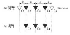
図5は、本発明の一実施形態に係る受信アレーアンテナの構成例を説明する図である。図5(a)は、本発明の一実施形態に係る不等ピッチの受信アレーアンテナの構成を示すブロック図である。図5(b)は、本実施形態に係る不等ピッチの受信アレーアンテナを構成する受信アンテナの一部を示すブロック図である。 FIG. 5 is a diagram illustrating a configuration example of a receiving array antenna according to an embodiment of the present invention. FIG. 5A is a block diagram showing a configuration of a receiving array antenna with unequal pitches according to an embodiment of the present invention. FIG. 5B is a block diagram showing a part of the receiving antennas constituting the unequal pitch receiving array antenna according to the present embodiment.
図5(a)に示されるように、本実施形態に係る不等ピッチの受信アレーアンテナは、n(本実施形態では、n=5)個の受信アンテナ1−1〜1−5を一列に並べた配置で構成されている。第1の受信アンテナ1−1と第2の受信アンテナ1−2との間隔(ピッチ)はd2であり、第2の受信アンテナ1−2と第3の受信アンテナ1−3との間隔はd1であり、第3の受信アンテナ1−3と第4の受信アンテナ1−4との間隔はd1であり、第4の受信アンテナ1−4と第5の受信アンテナ1−5との間隔はd2である。 As shown in FIG. 5A, the unequal pitch receiving array antenna according to the present embodiment includes n (in this embodiment, n = 5) receiving antennas 1-1 to 1-5 in a line. It consists of a side-by-side arrangement. The distance (pitch) between the first receiving antenna 1-1 and the second receiving antenna 1-2 is d2, and the distance between the second receiving antenna 1-2 and the third receiving antenna 1-3 is d1. The distance between the third reception antenna 1-3 and the fourth reception antenna 1-4 is d1, and the distance between the fourth reception antenna 1-4 and the fifth reception antenna 1-5 is d2. It is.
ここで、間隔d1と間隔d2は、それぞれ、異なる値である(d1≠d2)。本実施形態では、d1の方がd2よりも大きい(d1>d2)。
また、間隔d1と間隔d2は、整数倍の関係がない(d1≠p・d2:p=1、2、3、・・・)。
また、全ての受信アンテナ1−1〜1−5について、隣接する受信アンテナの間隔の平均値(平均ピッチ)をd0とする(d0=(d2+d1+d1+d2)/4)。Here, the interval d1 and the interval d2 are different values (d1 ≠ d2). In the present embodiment, d1 is larger than d2 (d1> d2).
Further, the interval d1 and the interval d2 do not have an integer multiple relationship (d1 ≠ p · d2: p = 1, 2, 3,...).
In addition, for all the receiving antennas 1-1 to 1-5, the average value (average pitch) between adjacent receiving antennas is set to d0 (d0 = (d2 + d1 + d1 + d2) / 4).
なお、n個の受信アンテナ1−1〜1−nから構成される受信アレーアンテナにおいて、i=1、2、・・・(n−1)として、(n−1)個の隣接する受信アンテナの間隔をそれぞれd(i)と表すと、全ての受信アンテナ1−1〜1−nについての平均の間隔(平均ピッチ)d0は、式(3)で表される。 In the receiving array antenna composed of n receiving antennas 1-1 to 1-n, (n−1) adjacent receiving antennas, where i = 1, 2,... (N−1). Is expressed as d (i), the average interval (average pitch) d0 for all the receiving antennas 1-1 to 1-n is expressed by equation (3).
d0=Σd(i)/(n−1)
(ただしΣは、i=1〜(n−1)のときの和を取る) ・・(3)d0 = Σd (i) / (n-1)
(However, Σ is the sum when i = 1 to (n−1).) (3)
図5(b)に示されるように、本実施形態に係る不等ピッチの受信アレーアンテナを構成する受信アンテナの一部を使用することができる。この例では、3個の受信アンテナとして、第2の受信アンテナ1−2と、第3の受信アンテナ1−3と、第4の受信アンテナ1−4を使用する。この場合、隣接する受信アンテナの間隔はいずれも等しい間隔d1となる。 As shown in FIG. 5B, a part of the receiving antennas constituting the unequal pitch receiving array antenna according to the present embodiment can be used. In this example, a second receiving antenna 1-2, a third receiving antenna 1-3, and a fourth receiving antenna 1-4 are used as three receiving antennas. In this case, the interval between adjacent receiving antennas is equal to the interval d1.
なお、このように一部の受信アンテナ1−2〜1−4のみを使用することは、一例として、制御部6などにより、使用する受信アンテナ1−2〜1−4により受信された信号に関する処理を信号処理部20で行うとともに、使用しない受信アンテナ1−1、1−5により受信された信号に関する処理を信号処理部20で行わないように制御する構成によって、実現することができる。
他の構成例として、このように一部の受信アンテナ1−2〜1−4のみを使用することは、制御部6などにより、使用する受信アンテナ1−2〜1−4の接続をスイッチなどによりオンにするとともに、使用しない受信アンテナ1−1、1−5の接続をスイッチなどによりオフにする構成によって、実現することができる。Note that using only some of the reception antennas 1-2 to 1-4 in this way relates to signals received by the reception antennas 1-2 to 1-4 used by the
As another configuration example, using only a part of the reception antennas 1-2 to 1-4 in this way means that the
本実施形態では、図5(a)に示されるように、全ての受信アンテナ1−1〜1−5を使用する不等ピッチの受信アレーアンテナを「Aタイプ」(5チャンネルの不等間隔アレーAのタイプ)と称し、また、図5(b)に示されるように、一部の受信アンテナ1−2〜1−4を使用する等ピッチの受信アレーアンテナを「Bタイプ」(3チャンネルの等間隔アレーBのタイプ)と称して、説明を行う。 In this embodiment, as shown in FIG. 5 (a), an unequal pitch receiving array antenna using all the receiving antennas 1-1 to 1-5 is referred to as "A type" (5 channel unequal interval array). As shown in FIG. 5B, an equal pitch receiving array antenna using a part of receiving antennas 1-2 to 1-4 is referred to as “B type” (3-channel type). This will be described as “equally spaced array B type”.
本実施形態では、概略的には、図5(a)(または、図5(b))に示される受信アンテナの配置を用いて、対象物(反射物)からの反射波を受信して、ミキサ2−1〜2−nによりミキシングすることで、ビート信号を生成する。このビート信号をA/D変換器5によりデジタル信号にしてメモリ21に取り込み、信号処理部20の周波数分離処理部22でFFT処理することにより、反射物に対する周波数成分を抽出する。そして、第1〜第3の各変調周波数の各増加区間(上昇部分)と各減少区間(下降部分)において抽出された周波数成分の組合わせに基づいて、本実施形態に係るレーダ装置と対象物との距離と相対速度を算出する。 In the present embodiment, schematically, a reflected wave from an object (reflecting object) is received using the arrangement of receiving antennas shown in FIG. 5A (or FIG. 5B), and A beat signal is generated by mixing with the mixers 2-1 to 2-n. This beat signal is converted into a digital signal by the A /
また、信号処理部20の周波数分離処理部22により抽出された反射物に対する周波数成分に対して、方位検出部28により対象物の方位を検出する。また、折返しターゲット判定部29は、折り返しであるか否かを判定する。
この場合に、方位検出部28及び折返しターゲット判定部29で使用されるアルゴリズムでは、方位検出範囲の内に存在する対象物については方位検出範囲の内にある本物として検出されるが、方位検出範囲の外に存在する対象物については方位検出範囲の内に折返した位置で検出される。Further, the direction of the object is detected by the
In this case, according to the algorithm used in the
そこで、本実施形態では、図5(a)に示される「Aタイプ」のように異なる間隔d1、d2で受信アンテナを並べた不等ピッチの受信アレーアンテナを用いた場合における全てのチャンネルを使用した対象物の方位検出を行うとともに、図5(b)に示される「Bタイプ」のように等しい間隔d1で受信アンテナを並べた等ピッチの受信アレーアンテナを用いた場合における一部のチャンネルを使用した対象物の方位検出を行う。 Therefore, in this embodiment, all channels in the case of using reception array antennas of unequal pitch in which reception antennas are arranged at different intervals d1 and d2 as in “A type” shown in FIG. 5A are used. In addition to detecting the orientation of the target object, some channels in the case of using a reception array antenna of equal pitch in which reception antennas are arranged at equal intervals d1 as shown in “B type” shown in FIG. The direction of the used object is detected.
ここで、受信アレーアンテナでは、隣接する受信アンテナの間隔の平均値(平均ピッチ)で方位検出範囲の広さが決まる。本実施形態では、平均ピッチがd0(d1とd2の平均値)となる「Aタイプ」の受信アレーアンテナと、平均ピッチがd1となる「Bタイプ」の受信アレーアンテナとでは、方位検出範囲の広さが異なっている。このため、「Aタイプ」の受信アレーアンテナを用いた場合における方位検出結果と、「Bタイプ」の受信アレーアンテナを用いた場合における方位検出結果との組合わせでは、対象物が両方の方位検出範囲の内(つまり、狭い方の方位検出範囲の内)に存在する場合には互いの方位検出結果が一致するが、対象物が少なくとも一方の方位検出範囲の外(つまり、少なくとも狭い方の方位検出範囲の外であって、2つの方位検出範囲の共通部分の外)に存在する場合には互いの方位検出結果に差分(ずれ)が生じる算出結果となる。このような互いの方位検出結果の差分は、互いの方位検出範囲の差分に応じたものとなる。 Here, in the receiving array antenna, the width of the azimuth detection range is determined by the average value (average pitch) between the adjacent receiving antennas. In the present embodiment, the “A type” receiving array antenna having an average pitch of d0 (average value of d1 and d2) and the “B type” receiving array antenna having an average pitch of d1 The area is different. For this reason, in the combination of the azimuth detection result when the “A type” receiving array antenna is used and the azimuth detection result when the “B type” receiving array antenna is used, the object is detected in both directions. If they are within the range (that is, within the narrower direction detection range), the direction detection results match each other, but the object is outside at least one of the direction detection ranges (that is, at least the narrower direction) If it exists outside the detection range and outside the common part of the two azimuth detection ranges), a calculation result in which a difference (shift) occurs in the azimuth detection results of each other. The difference between the mutual azimuth detection results corresponds to the difference between the azimuth detection ranges.
このことを利用する。具体的には、これら2つの方位検出結果が一致した場合には、これら2つの方位検出範囲の内に存在する対象物であると判定し、これら2つの方位検出結果が一致しなかった場合には、少なくとも一方の方位検出範囲の外に存在する対象物であると判定する。これにより、対象物が方位検出範囲(ここでは、2つの方位検出範囲の共通部分)の内または外のいずれに存在するのかを判別することができる。 Take advantage of this. Specifically, when these two azimuth detection results match, it is determined that the object exists within these two azimuth detection ranges, and when these two azimuth detection results do not match Is determined to be an object existing outside at least one of the azimuth detection ranges. This makes it possible to determine whether the object is present in or out of the azimuth detection range (here, the common part of the two azimuth detection ranges).
また、本実施形態では、上記した2つの方位検出結果が一致しなかった場合には、少なくとも一方の方位検出範囲の外に存在する対象物であると判定し、折返しが1回であると仮定して(本実施形態では、狭い方の方位検出範囲について2回以上の折返しではないと仮定して)、これら2つの方位検出結果の関係に基づいて、この対象物の方位を決定することが可能である。これにより、レーダ装置に備える受信アンテナ1−1〜1−5を変更することなく、方位検出範囲の実質的な広角化を実現することができる。 In the present embodiment, if the above two azimuth detection results do not match, it is determined that the object exists outside at least one of the azimuth detection ranges, and it is assumed that the return is performed once. (In this embodiment, it is assumed that the narrower direction detection range is not folded twice or more), and the direction of the object can be determined based on the relationship between the two direction detection results. Is possible. Thereby, a substantial widening of the azimuth detection range can be realized without changing the receiving antennas 1-1 to 1-5 included in the radar apparatus.
なお、この例では、少なくとも一方の方位検出範囲の外に存在する対象物について、折返しが1回であると仮定しているため、狭い方の方位検出範囲について2回以上の折返しがある場合には、対象物の方位は正確には決定されない。 In this example, since it is assumed that the object that exists outside at least one of the azimuth detection ranges is folded once, when there are two or more folds for the narrower direction detection range. The orientation of the object is not accurately determined.
図6は、本発明の一実施形態に係る方位検出部28と折返しターゲット判定部29において行われる処理の手順の一例を示すフローチャート図である。 FIG. 6 is a flowchart illustrating an example of a procedure of processing performed in the
(ステップS101)方位検出部28は、周波数分離処理部22からデータ(本実施形態では、反射物に対する周波数成分に関するデータ)を受け取る。(Step S <b> 101) The
(ステップS102)方位検出部28は、「Aタイプ」である不等間隔アレーAを用いて、方位検出の処理を行い、対象物の方位(方位角度の位置)を検出する。
(ステップS103)次に、方位検出部28は、「Bタイプ」である等間隔アレーBを用いて、方位検出の処理を行い、対象物の方位(方位角度の位置)を検出する。
なお、ステップS102の処理とステップS103の処理の順序は、逆であってもよい。(Step S102) The
(Step S103) Next, the
Note that the order of the processing in step S102 and the processing in step S103 may be reversed.
(ステップS104〜ステップS106)折返しターゲット判定部29は、それぞれの対象物ごとに、これら2つの方位検出の結果を比較する処理を行う。
具体的には、ステップS104〜ステップS106を以下のように行う。
(ステップS104)折返しターゲット判定部29は、「Aタイプ」について得られた方位検出の結果(方位角度の位置)と「Bタイプ」について得られた方位検出の結果(方位角度の位置)とに差分があるか否かを判定する。
(ステップS105)この判定の結果、折返しターゲット判定部29は、「Aタイプ」について得られた方位検出の結果(方位角度の位置)と「Bタイプ」について得られた方位検出の結果(方位角度の位置)とに差分がないと判定した場合、方位検出範囲(ここでは、2つの方位検出範囲の共通部分)の内に存在する対象物(本物)であるとして、例えば、「Aタイプ」について得られた方位検出の結果(方位角度の位置)を対象物の方位のデータとして設定する。(Steps S104 to S106) The return
Specifically, step S104 to step S106 are performed as follows.
(Step S <b> 104) The return
(Step S105) As a result of this determination, the return
なお、この場合に、「Aタイプ」について得られた方位検出の結果(方位角度の位置)の代わりに、「Bタイプ」について得られた方位検出の結果(方位角度の位置)を対象物の方位のデータとして設定することも可能である。 In this case, instead of the azimuth detection result (azimuth angle position) obtained for "A type", the azimuth detection result (azimuth angle position) obtained for "B type" It is also possible to set as azimuth data.
(ステップS6)一方、前記の判定の結果、折返しターゲット判定部29は、「Aタイプ」について得られた方位検出の結果(方位角度の位置)と「Bタイプ」について得られた方位検出の結果(方位角度の位置)とに差分があると判定した場合、方位検出範囲(ここでは、2つの方位検出範囲の共通部分)の外に存在する対象物が方位検出範囲(ここでは、2つの方位検出範囲の共通部分)の内に折返した位置で検出されたとみなして、これらの方位検出の結果については対象物に関するデータに含めないように除外する。(Step S6) On the other hand, as a result of the determination, the turnaround
なお、「Aタイプ」について得られた方位検出の結果(方位角度の位置)と「Bタイプ」について得られた方位検出の結果(方位角度の位置)とに差分があるか否かを判定する手法としては、一例として、これら2つの方位検出の結果の値(方位角度の位置を示す値)が同一でない場合(つまり、異なる場合)に差分があると判定し、これら2つの方位検出の結果の値が同一である場合に差分がないと判定する手法を用いることができる。
他の例として、これら2つの方位検出の結果の値の誤差を多少許容するようなときには、これら2つの方位検出の結果の値の差があらかじめ定められた閾値以上である場合に差分があると判定し、これら2つの方位検出の結果の値の差が当該閾値未満である場合に差分がないと判定する手法を用いることもできる。It is determined whether or not there is a difference between the direction detection result (azimuth angle position) obtained for “A type” and the direction detection result (azimuth angle position) obtained for “B type”. As a technique, for example, it is determined that there is a difference when the values (results indicating the position of the azimuth angle) of these two azimuth detection results are not the same (that is, when they are different), and the results of these two azimuth detections A method of determining that there is no difference in the case where the values of the two are the same can be used.
As another example, when an error in the values of these two azimuth detection results is allowed to some extent, if the difference between the two azimuth detection result values is equal to or greater than a predetermined threshold, there is a difference. It is also possible to use a method of determining and determining that there is no difference when the difference between the values of these two azimuth detection results is less than the threshold value.
このように、図6に示されるフローチャートの例では、方位検出部28は、反射物に対する周波数成分に対して、「Aタイプ」について方位検出処理を行って対象物の方位情報を算出するとともに、「Bタイプ」について方位検出処理を行って対象物の方位情報を算出する。折返しターゲット判定部29は、これら2つのタイプについて対象物の方位情報を算出した後に、それぞれの対象物ごとに、これら2つのタイプについて得られた対象物の方位情報を比較する。そして、折返しターゲット判定部29は、それぞれの対象物ごとに、これら2つのタイプについて得られた対象物の方位情報が一致(誤差が許容されてもよい)している場合に、方位検出範囲(ここでは、2つの方位検出範囲の共通部分)の内に存在する対象物であると判定して、そのデータを設定する。 As described above, in the example of the flowchart illustrated in FIG. 6, the
なお、図6に示されるフローチャートの例では、折返しターゲット判定部29は、2つのタイプについて得られた対象物の方位情報が一致(誤差が許容されてもよい)していない場合には、方位検出範囲(ここでは、2つの方位検出範囲の共通部分)の外に存在する対象物であると判定して、その判定結果をステータスなどに保持させずに、対象物のデータから除外することを行ったが、他の例として、2つのタイプについて得られた対象物の方位情報が一致(誤差が許容されてもよい)していない場合には、方位検出範囲(ここでは、2つの方位検出範囲の共通部分)の外に存在する対象物であると判定して、その判定結果をステータスなどに保持させることが行われてもよい。
なお、本実施形態では、折り返しターゲット判定部29を備える例を説明したが、折返しターゲット判定部29の機能を方位検出部28が備えるようにしてもよい。In the example of the flowchart shown in FIG. 6, the return
In the present embodiment, the example in which the return
次に、図7〜図9を参照して、折返しターゲット判定部29が行う折り返しターゲット判定について説明する。図7は、本発明の一実施形態に係る不等間隔アレーにおける折り返しを説明する図である。図7(a)は、方位検出範囲(FOV)の内に対象物が存在する場合の様子の例を示す図である。図7(b)は、方位検出範囲(FOV)の外(左)に対象物が存在する場合の様子の例を示す図である。図7(c)は、方位検出範囲(FOV)の外(右)に対象物が存在する場合の様子の例を示す図である。 Next, the return target determination performed by the return
図7(a)、図7(b)、図7(c)に示される方位検出範囲(FOV)は、「Aタイプ」の方位検出範囲と「Bタイプ」の方位検出範囲とで狭い方の方位検出範囲(FOV)を表す。この例では、「Bタイプ」の方位検出範囲の方が「Aタイプ」の方位検出範囲よりも狭いとする。 The azimuth detection range (FOV) shown in FIG. 7A, FIG. 7B, and FIG. 7C is the narrower of the “A type” azimuth detection range and the “B type” azimuth detection range. Represents the azimuth detection range (FOV). In this example, it is assumed that the “B type” orientation detection range is narrower than the “A type” orientation detection range.
また、方位検出範囲(FOV)の外(左)は、対象物の方位におけるマイナス方向またはプラス方向のうちの一方の方向で、方位検出範囲(FOV)の内から外れた折返しの領域(折返しエリア)を表す。また、方位検出範囲(FOV)の外(右)は、対象物の方位におけるマイナス方向またはプラス方向のうちの他方の方向で、方位検出範囲(FOV)の内から外れた折返しの領域(折返しエリア)を表す。 Further, the outside (left) of the azimuth detection range (FOV) is one of the minus direction and the plus direction in the azimuth of the object, and is a folded area (folding area) outside the azimuth detection range (FOV). ). Further, outside (right) of the azimuth detection range (FOV) is a fold-back area (folding area) that is out of the azimuth detection range (FOV) in the other of the minus direction and the plus direction in the azimuth of the object. ).
図7(a)の例では、対象物(ターゲット)101が方位検出範囲(FOV)の内に存在する。この場合、「Aタイプ」を用いて方位検出を行った結果として得られる方位(方位角度)を表すスペクトル(この例では、スペクトル102とする)のピーク位置と、「Bタイプ」を用いて方位検出を行った結果として得られる方位(方位角度)を表すスペクトル(この例では、スペクトル103とする)のピーク位置とが一致する。このため、折り返しターゲット判定部29は、この一致したピーク位置に対応する方位角度の位置(ターゲット検出位置)104を対象物101の方位として検出する。 In the example of FIG. 7A, the object (target) 101 exists in the azimuth detection range (FOV). In this case, the peak position of a spectrum (in this example, spectrum 102) representing the azimuth (azimuth angle) obtained as a result of performing azimuth detection using “A type”, and the azimuth using “B type” The peak position of the spectrum (in this example, the spectrum 103) representing the azimuth (azimuth angle) obtained as a result of the detection matches. For this reason, the return
図7(b)の例では、対象物(ターゲット)111が方位検出範囲(FOV)の外(左)に存在する。この場合、「Aタイプ」を用いて方位検出を行った結果として得られる方位(方位角度)を表すスペクトル(この例では、スペクトル112とする)のピーク位置と、「Bタイプ」を用いて方位検出を行った結果として得られる方位(方位角度)を表すスペクトル(この例では、スペクトル113とする)のピーク位置とは、ずれて不一致となる。この例では、スペクトル113のピーク位置の方がスペクトル112のピーク位置よりも左側にある。 In the example of FIG. 7B, the target (target) 111 exists outside (left) the azimuth detection range (FOV). In this case, the peak position of a spectrum (in this example, spectrum 112) representing the azimuth (azimuth angle) obtained as a result of performing azimuth detection using “A type” and the azimuth using “B type” The peak position of the spectrum (in this example, spectrum 113) representing the azimuth (azimuth angle) obtained as a result of the detection is shifted and does not match. In this example, the peak position of the
このとき、対象物111の実際の方位(折返しがないとしたときの方位)にはスペクトル114のピーク位置が対応するが、方位検出処理では、1回の折返し位置として、ターゲット検出位置115辺りが対象物111の方位として検出される。
ここで、折り返しターゲット判定部29は、2つのスペクトル112、113のピーク位置の関係を参照して、左方向への折返しであることを判定する。そして、折り返しターゲット判定部29は、1回の折返しであるとみなして、折返しを考慮することで、方位検出処理の結果(例えば、2つのスペクトル112、113のピーク位置の関係)に基づいて、対象物111の実際の方位を決定することができる。これにより、本実施形態によれば、実質的に方位検出範囲(FOV)を広げたことと等価な効果を得ることができる。At this time, the peak position of the
Here, the return
図7(c)の例では、対象物(ターゲット)121が方位検出範囲(FOV)の外(右)に存在する。この場合、「Aタイプ」を用いて方位検出を行った結果として得られる方位(方位角度)を表すスペクトル(この例では、スペクトル122とする)のピーク位置と、「Bタイプ」を用いて方位検出を行った結果として得られる方位(方位角度)を表すスペクトル(この例では、スペクトル123とする)のピーク位置とは、ずれて不一致となる。この例では、スペクトル123のピーク位置の方がスペクトル122のピーク位置よりも右側にある。 In the example of FIG. 7C, the target (target) 121 exists outside (right) the azimuth detection range (FOV). In this case, the peak position of a spectrum (in this example, spectrum 122) representing the azimuth (azimuth angle) obtained as a result of performing azimuth detection using “A type” and the azimuth using “B type” The peak position of the spectrum (in this example, the spectrum 123) representing the azimuth (azimuth angle) obtained as a result of the detection is shifted and becomes inconsistent. In this example, the peak position of the
このとき、対象物121の実際の方位(折返しがないとしたときの方位)にはスペクトル124のピーク位置が対応するが、方位検出処理では、1回の折返し位置として、ターゲット検出位置125辺りが対象物121の方位として検出される。
ここで、折り返しターゲット判定部29は、2つのスペクトル122、123のピーク位置の関係を参照し、右方向への折返しであることを判定する。そして、折り返しターゲット判定部29は、1回の折返しであるとみなして、折返しを考慮することで、方位検出処理の結果(例えば、2つのスペクトル122、123のピーク位置の関係)に基づいて、対象物121の実際の方位を決定することができる。これにより、本実施形態によれば、実質的に方位検出範囲(FOV)を広げたことと等価な効果を得ることができる。At this time, the peak position of the
Here, the return
図8及び図9に、本実施形態に係るレーダ装置に関するシミュレーションの結果を示す。図8は、シミュレーションにおける自車201と他車202との関係を示す図である。この例では、本実施形態に係るレーダ装置が搭載された自車201の前方方向(進行方
向)の軸に対して、Y[m](Yは0より大きい値)左の方に、対象物となる他車202
が存在する。FIG. 8 and FIG. 9 show simulation results regarding the radar apparatus according to the present embodiment. FIG. 8 is a diagram illustrating a relationship between the
Exists.
次に、シミュレーションの条件を説明する。
シミュレーションの条件は、受信アンテナ数(受信素子数)がN(Nは、例えば、3以上の整数)であり、受信アレーアンテナの中央ピッチd1(図5参照)がd0+α(αは、例えば、0より大きい値)であり、受信アレーアンテナの両端ピッチd2(図5参照)がd0−αであり、受信アレーアンテナの合成ピッチ(平均ピッチ)がd0である。Next, simulation conditions will be described.
The simulation condition is that the number of reception antennas (the number of reception elements) is N (N is an integer of 3 or more, for example), and the center pitch d1 (see FIG. 5) of the reception array antenna is d0 + α (α is, for example, 0 Larger value), the both-end pitch d2 (see FIG. 5) of the receiving array antenna is d0-α, and the combined pitch (average pitch) of the receiving array antenna is d0.
図9は、自車201に搭載された本実施形態に係るレーダ装置に関するシミュレーションの結果を示す図である。図9では、横軸は本実施形態に係るレーダ装置により検出される対象物(他車202)との距離(検出距離[m])を表し、縦軸は本実施形態に係るレーダ装置により検出される対象物(他車202)の方位角度(方位検出角度[deg])を表す。
図8における自車201と他車202との距離が遠い位置から次第に近い位置になっていく場合が、図9のグラフに反映されている。FIG. 9 is a diagram showing a result of a simulation related to the radar apparatus according to the present embodiment mounted on the
The case where the distance between the
図9に示されるグラフにおいて、自車201と他車202との距離がR2[m](R2は0より大きい値)辺りからR1[m](R1は、0より大きい値であり、R2より小さい値)辺りまでは、対象物(他車202)が方位検出範囲(ここでは、2つの方位検出範囲の共通部分)の内に存在し、「Aタイプ」の不等間隔アレーAを用いた方位検出の結果と「Bタイプ」の等間隔アレーBを用いた方位検出の結果とが一致する。この一致する方位検出の結果が、曲線1001で表されている。これにより、本物の方位角度が検出される。 In the graph shown in FIG. 9, the distance between the
一方、自車201と他車202との距離がR1[m]辺りより小さくなると、対象物(他車202)が方位検出範囲(ここでは、2つの方位検出範囲の共通部分)の外へ出て、「Aタイプ」の不等間隔アレーAを用いた方位検出の結果(曲線1002で表されている)と「Bタイプ」の等間隔アレーBを用いた方位検出の結果(曲線1003で表されている)とが不一致となってずれる。この場合、折返しの方位角度が検出される。 On the other hand, when the distance between the
以上のように、本実施形態に係る車載用のレーダ装置では、異なる第1〜第3の変調波に基づく送信波を送信し、この第1〜第3の変調波に基づく反射波である受信波に基づいて対象物を検出するようにした。すなわち、本実施形態では、遠距離の対象物に対して、第1及び第2の変調波に基づいて対象物を検出し、近距離の対象物に対して、第2及び第3の変調波に基づいて対象物を検出するようにした。この結果、例えば歩行者のように反射面積が小さくても、受信した信号に対して利得が大きい第3の変調波を用いて、対象物を検出することができる。 As described above, the in-vehicle radar device according to the present embodiment transmits transmission waves based on different first to third modulation waves, and receives a reflection wave based on the first to third modulation waves. The object was detected based on the wave. That is, in the present embodiment, the object is detected based on the first and second modulated waves with respect to the object at a long distance, and the second and third modulated waves are detected with respect to the object at a short distance. The object is detected based on the above. As a result, even if the reflection area is small, such as a pedestrian, the target can be detected using the third modulated wave having a large gain with respect to the received signal.
さらに、本実施形態に係る車載用のレーダ装置では、複数の受信アンテナ1−1〜1−nを異なる間隔d1、d2で並べた不等ピッチの受信アレーアンテナを用いて、2種類の平均的な間隔(平均ピッチ)d0、d1を有するアンテナの配置のそれぞれで対象物の方位検出を行い、それぞれの方位検出の結果の一致の有無を相互的に確認し、この確認の結果に基づいて、対象物が方位検出範囲の内に存在するかあるいは外に存在するかを判別する。従って、本実施形態に係る車載用のレーダ装置によれば、方位検出範囲に対して左右のいずれかの外に存在する対象物の折返し位置が検出された場合には、そのことを判定することができ、例えば、このような折返し位置の情報を対象物のデータから除外すること、または、1回の折返しであるとみなして、対象物の方位を検出することができる。
この結果、実施形態に係る車載用のレーダ装置では、対象物が遠距離に存在する反射波の振幅が大きい車両であっても、対象物が近距離に存在する反射波の振幅が小さい歩行者であっても、どちらの対象物も適切に検出することができる。Furthermore, in the on-vehicle radar device according to the present embodiment, two types of average antennas are used by using a reception array antenna with an unequal pitch in which a plurality of reception antennas 1-1 to 1-n are arranged at different intervals d1 and d2. Azimuth detection of the object in each of the arrangement of the antennas having a small interval (average pitch) d0, d1, and mutually confirm whether there is a match between the results of the respective azimuth detection, based on the result of this confirmation, It is determined whether the object is present within or outside the azimuth detection range. Therefore, according to the on-vehicle radar device according to the present embodiment, if a turn-back position of an object that exists outside either the left or right of the azimuth detection range is detected, it is determined. For example, it is possible to exclude the information on the folding position from the data of the object, or to detect the orientation of the object by regarding the information as one turn.
As a result, in the on-vehicle radar device according to the embodiment, even if the target object is a vehicle having a large reflected wave amplitude at a long distance, the pedestrian has a small reflected wave amplitude at which the target object exists at a short distance. Even so, both objects can be detected appropriately.
以上、本発明の実施形態について図面を参照して詳述してきたが、具体的な構成はこの実施形態に限られるものではなく、本発明の要旨を逸脱しない範囲の設計変更等も含まれる。 As mentioned above, although embodiment of this invention was explained in full detail with reference to drawings, the specific structure is not restricted to this embodiment, The design change etc. of the range which does not deviate from the summary of this invention are included.
また、上述した実施形態に係るレーダ装置の機能(例えば、信号処理部20における方位検出部28あるいは他の処理部22〜30のうちの1つ以上の処理部の機能)を実現するためのプログラムをコンピュータ読み取り可能な記録媒体に記録して、この記録媒体に記録されたプログラムをコンピュータシステムに読み込ませ、実行することにより、処理を行ってもよい。なお、ここで言う「コンピュータシステム」とは、OS(Operating System)や周辺機器等のハードウェアを含むものであってもよい。
また、「コンピュータ読み取り可能な記録媒体」とは、フレキシブルディスク、光磁気ディスク、ROM(Read Only Memory)、フラッシュメモリ等の書き込み可能な不揮発性メモリ、DVD(Digital Versatile Disk)等の可搬媒体、コンピュータシステムに内蔵されるハードディスク等の記憶装置のことを言う。Further, a program for realizing the function of the radar apparatus according to the above-described embodiment (for example, the function of one or more processing units among the
The “computer-readable recording medium” means a flexible disk, a magneto-optical disk, a ROM (Read Only Memory), a writable nonvolatile memory such as a flash memory, a portable medium such as a DVD (Digital Versatile Disk), A storage device such as a hard disk built in a computer system.
さらに、「コンピュータ読み取り可能な記録媒体」とは、インターネット等のネットワークや電話回線等の通信回線を介してプログラムが送信された場合のサーバやクライアントとなるコンピュータシステム内部の揮発性メモリ(例えばDRAM(Dynamic Random Access Memory))のように、一定時間プログラムを保持しているものも含むものとする。
また、上記のプログラムは、このプログラムを記憶装置等に格納したコンピュータシステムから、伝送媒体を介して、あるいは、伝送媒体中の伝送波により他のコンピュータシステムに伝送されてもよい。ここで、プログラムを伝送する「伝送媒体」は、インターネット等のネットワーク(通信網)や電話回線等の通信回線(通信線)のように情報を伝送する機能を有する媒体のことを言う。
また、上記のプログラムは、前述した機能の一部を実現するためのものであってもよい。さらに、前述した機能をコンピュータシステムにすでに記録されているプログラムとの組合わせで実現できるもの、いわゆる差分ファイル(差分プログラム)であってもよい。Further, the “computer-readable recording medium” refers to a volatile memory (for example, DRAM (DRAM) inside a computer system that becomes a server or a client when a program is transmitted through a network such as the Internet or a communication line such as a telephone line. Dynamic Random Access Memory)) that holds a program for a certain period of time is also included.
The program may be transmitted from a computer system storing the program in a storage device or the like to another computer system via a transmission medium or by a transmission wave in the transmission medium. Here, the “transmission medium” for transmitting a program refers to a medium having a function of transmitting information, such as a network (communication network) such as the Internet or a communication line (communication line) such as a telephone line.
Further, the above program may be for realizing a part of the functions described above. Furthermore, what can implement | achieve the function mentioned above in combination with the program already recorded on the computer system, and what is called a difference file (difference program) may be sufficient.
1−1〜1−n…受信アンテナ 2−1〜2−n…ミキサ 3−1〜3−n…フィルタ
4…スイッチ 5…A/D変換器 6…制御部 7…三角波生成部 8…VCO 9…分配器 10…送信アンテナ 41−1〜41−n、42、43、44、45−1〜45−n…アンプ(増幅器) 20…信号処理部 21…メモリ 22…周波数分解処理部 23…ピーク検知部 24…ピーク組合せ部 25…距離検出部 26…速度検出部 27…ペア確定部 28…方位検出部 29…折り返しターゲット判定部 30…ターゲット確定部DESCRIPTION OF SYMBOLS 1-1 to 1-n ... Reception antenna 2-1 to 2-n ... Mixer 3-1 to 3-n ... Filter 4 ...
Claims (7)
Translated fromJapanese前記異なる第1〜第3の変調波に基づく送信波を送信する送信アンテナと、
送信波が対象物によって反射されて到来する受信波を受信する受信アンテナと、
前記受信波から前記異なる第1〜第3の変調波に基づく信号を検出し、検出した信号に基づいて、前記対象物の方位を検出する方位検出部と、
を備えることを特徴とする車載用のレーダ装置。A transmission wave generator for generating different first to third modulated waves;
A transmission antenna for transmitting a transmission wave based on the different first to third modulation waves;
A receiving antenna that receives a received wave that is transmitted by the reflected wave reflected by the object;
Detecting a signal based on the different first to third modulated waves from the received wave, and detecting a direction of the object based on the detected signal;
An on-vehicle radar device comprising:
ことを特徴とする請求項1に記載の車載用のレーダ装置。The transmission wave is a signal in which the first modulation wave, the second modulation wave, and the third modulation wave are arranged in this order, and the first to third modulation waves are arranged at predetermined time intervals. The on-vehicle radar device according to claim 1, comprising a wave.
ことを特徴とする請求項1または請求項2に記載の車載用のレーダ装置。The modulation time of the first modulation wave is longer than the modulation time of the second and third modulation waves, and the modulation time of the second modulation wave is longer than the modulation time of the third modulation wave. The on-vehicle radar device according to claim 1, wherein the radar device is mounted on a vehicle.
前記第1の変調波に基づく信号と前記第2の変調波に基づく信号とに基づき、第1対象物の方位を検出し、前記第2の変調波に基づく信号と前記第3の変調波に基づく信号とに基づき、第2対象物の方位を検出する
ことを特徴とする請求項1から請求項3のいずれか1項に記載の車載用のレーダ装置。The bearing detection unit
Based on the signal based on the first modulated wave and the signal based on the second modulated wave, the orientation of the first object is detected, and the signal based on the second modulated wave and the third modulated wave are detected. The in-vehicle radar device according to any one of claims 1 to 3, wherein the orientation of the second object is detected based on the signal based on the signal.
受信アレーアンテナとして、整数倍の関係にない2種類以上の平均ピッチの受信アレーアンテナを実現する複数の受信アンテナを備え、
前記2種類以上の平均ピッチの受信アレーアンテナのそれぞれによる受信信号に基づいて前記対象物の方位を検出する方位検出処理を行い、これら2種類以上の平均ピッチの受信アレーアンテナのそれぞれによる受信信号に基づいて検出された前記対象物の方位が一致すると判定した場合には当該検出された前記対象物の方位は正しいと判定し、これら2種類以上の平均ピッチの受信アレーアンテナのそれぞれによる受信信号に基づいて検出された前記対象物の方位が不一致であると判定した場合には当該検出された前記対象物の方位は正しくないと判定する判定部
を備えることを特徴とする請求項1から請求項4のいずれか1項に記載の車載用のレーダ装置。The receiving antenna is
As a receiving array antenna, it has a plurality of receiving antennas that realize two or more types of average pitch receiving array antennas that are not in an integer multiple relationship,
An azimuth detection process is performed to detect the azimuth of the object based on the received signals from the two or more types of receiving antennas having an average pitch, and the received signals from the two or more types of receiving antennas having an average pitch are obtained. When it is determined that the orientations of the detected objects match based on each other, it is determined that the detected orientations of the objects are correct, and the signals received by the reception array antennas having two or more average pitches are respectively received. 2. The apparatus according to claim 1, further comprising: a determination unit that determines that the detected orientation of the target object is incorrect when it is determined that the orientation of the target object detected based on the mismatch is detected. 5. The on-vehicle radar device according to any one of 4 above.
送信波生成部が、異なる第1〜第3の変調波を生成する手順と、
送信アンテナが、前記異なる第1〜第3の変調波に基づく送信波を送信する手順と、
受信アンテナが、送信波が対象物によって反射されて到来する受信波を受信する手順と、
方位検出部が、前記受信波から前記異なる第1〜第3の変調波に基づく信号を検出し、検出した信号に基づいて、前記対象物の方位を検出する手順と、
を含むことを特徴とする車載用のレーダ方法。A radar method for an on-vehicle radar device,
A procedure in which the transmission wave generator generates different first to third modulated waves;
A transmission antenna transmitting a transmission wave based on the different first to third modulation waves;
A procedure in which a receiving antenna receives a received wave that is transmitted by a reflected wave reflected by an object;
A direction detecting unit detects a signal based on the different first to third modulated waves from the received wave, and detects a direction of the object based on the detected signal;
An on-vehicle radar method comprising:
送信波生成部が、異なる第1〜第3の変調波を生成する手順と、
送信アンテナが、前記異なる第1〜第3の変調波に基づく送信波を送信する手順と、
受信アンテナが、送信波が対象物によって反射されて到来する受信波を受信する手順と、
方位検出部が、前記受信波から前記異なる第1〜第3の変調波に基づく信号を検出し、検出した信号に基づいて、前記対象物の方位を検出する手順と、
を実行させるための車載用のレーダプログラム。In the computer of the on-vehicle radar device,
A procedure in which the transmission wave generator generates different first to third modulated waves;
A transmission antenna transmitting a transmission wave based on the different first to third modulation waves;
A procedure in which a receiving antenna receives a received wave that is transmitted by a reflected wave reflected by an object;
A direction detecting unit detects a signal based on the different first to third modulated waves from the received wave, and detects a direction of the object based on the detected signal;
In-vehicle radar program to execute
Priority Applications (2)
| Application Number | Priority Date | Filing Date | Title |
|---|---|---|---|
| JP2012137763AJP2014002053A (en) | 2012-06-19 | 2012-06-19 | On-vehicle rader system, on-vehicle radar method and on-vehicle radar program |
| US13/921,794US9250318B2 (en) | 2012-06-19 | 2013-06-19 | On-board radar apparatus, object detection method, and object detection program |
Applications Claiming Priority (1)
| Application Number | Priority Date | Filing Date | Title |
|---|---|---|---|
| JP2012137763AJP2014002053A (en) | 2012-06-19 | 2012-06-19 | On-vehicle rader system, on-vehicle radar method and on-vehicle radar program |
Publications (1)
| Publication Number | Publication Date |
|---|---|
| JP2014002053Atrue JP2014002053A (en) | 2014-01-09 |
Family
ID=49777558
Family Applications (1)
| Application Number | Title | Priority Date | Filing Date |
|---|---|---|---|
| JP2012137763APendingJP2014002053A (en) | 2012-06-19 | 2012-06-19 | On-vehicle rader system, on-vehicle radar method and on-vehicle radar program |
Country Status (2)
| Country | Link |
|---|---|
| US (1) | US9250318B2 (en) |
| JP (1) | JP2014002053A (en) |
Cited By (6)
| Publication number | Priority date | Publication date | Assignee | Title |
|---|---|---|---|---|
| JP2017044689A (en)* | 2015-08-27 | 2017-03-02 | 日本電産エレシス株式会社 | Radar antenna and radar apparatus |
| JP2020118644A (en)* | 2019-01-28 | 2020-08-06 | 株式会社デンソーテン | Arrival direction estimating device and arrival direction estimating method |
| JP2020186974A (en)* | 2019-05-13 | 2020-11-19 | 株式会社デンソーテン | Signal processing device, radar device, and signal processing method |
| US10914829B2 (en) | 2017-01-27 | 2021-02-09 | Panasonic Intellectual Property Management Co., Ltd. | Positioning sensor, sensor, and method |
| JP2021039057A (en)* | 2019-09-05 | 2021-03-11 | 株式会社Soken | Folding determination device |
| WO2021106540A1 (en) | 2019-11-26 | 2021-06-03 | 京セラ株式会社 | Electronic device, method for controlling electronic device, and program |
Families Citing this family (6)
| Publication number | Priority date | Publication date | Assignee | Title |
|---|---|---|---|---|
| US10225810B2 (en)* | 2014-08-06 | 2019-03-05 | Samsung Electronics Co., Ltd. | Method and apparatus for transmitting/receiving synchronization signal in device-to-device communication system |
| CN105356980A (en)* | 2014-08-20 | 2016-02-24 | 中兴通讯股份有限公司 | Response message sending method and device |
| CN107810430A (en)* | 2015-06-17 | 2018-03-16 | 纽威莱克公司 | mmWave sensor system for parking assistance |
| JP6560165B2 (en)* | 2016-07-08 | 2019-08-14 | 株式会社Soken | Radar equipment |
| WO2020030281A1 (en)* | 2018-08-10 | 2020-02-13 | HELLA GmbH & Co. KGaA | Method for evaluating overlapping targets |
| DE102020109502A1 (en)* | 2020-04-06 | 2021-10-07 | HELLA GmbH & Co. KGaA | Method for determining an angle information |
Family Cites Families (26)
| Publication number | Priority date | Publication date | Assignee | Title |
|---|---|---|---|---|
| US4862180A (en) | 1985-06-12 | 1989-08-29 | Westinghouse Electric Corp. | Discrete source location by adaptive antenna techniques |
| US5027122A (en) | 1990-03-12 | 1991-06-25 | Raytheon Company | Method and apparatus for doppler velocity de-aliasing |
| US5525997A (en) | 1993-04-30 | 1996-06-11 | Hughes Aircraft Company | Self-calibrating, eigenstructure based method and means of direction finding |
| US5457466A (en) | 1993-09-07 | 1995-10-10 | Litton Systems Inc. | Emitter azimuth and elevation direction finding using only linear interferometer arrays |
| US5633642A (en)* | 1993-11-23 | 1997-05-27 | Siemens Aktiengesellschaft | Radar method and device for carrying out the method |
| US5450089A (en) | 1994-06-30 | 1995-09-12 | Hughes Aircraft Company | Monopulse thresholding |
| FR2737346B1 (en) | 1995-07-24 | 1997-08-29 | Alcatel Telspace | METHOD FOR CONTROLLING AN ANTENNA POSITIONER FOR SCROLLING SATELLITE |
| DE19748604B4 (en) | 1997-11-04 | 2009-08-27 | Robert Bosch Gmbh | Method for determining a lateral and / or a vertical angle in a multi-beam radar system, and device for carrying out the method |
| US6087974A (en) | 1998-08-03 | 2000-07-11 | Lockheed Martin Corporation | Monopulse system for target location |
| US6225949B1 (en) | 1998-12-22 | 2001-05-01 | Lockheed Martin Corporation | Method and apparatus for a ring interferometer |
| US6356231B1 (en) | 2000-06-29 | 2002-03-12 | Lockheed Martin Corporation | Monopulse radar processor for resolving two sources |
| DE10038912A1 (en) | 2000-08-09 | 2002-02-21 | Daimler Chrysler Ag | Repositioning moving target in SAR images consisting of multichannel range/Doppler measuring data with Doppler resolution cells |
| KR100452536B1 (en) | 2000-10-02 | 2004-10-12 | 가부시키가이샤 엔.티.티.도코모 | Mobile communication base station equipment |
| US7042386B2 (en) | 2001-12-11 | 2006-05-09 | Essex Corporation | Sub-aperture sidelobe and alias mitigation techniques |
| JP2003248054A (en) | 2002-02-27 | 2003-09-05 | Hitachi Ltd | Monopulse radar device |
| JP3610052B2 (en) | 2002-04-18 | 2005-01-12 | 三菱電機株式会社 | Radar equipment |
| JP2004170371A (en) | 2002-11-22 | 2004-06-17 | Denso Corp | Azimuth detecting device |
| JP4093109B2 (en)* | 2003-05-15 | 2008-06-04 | 株式会社デンソー | Radar equipment for vehicles |
| JP5462626B2 (en) | 2007-08-08 | 2014-04-02 | 富士通テン株式会社 | Radar apparatus and azimuth detection method |
| JP4415040B2 (en) | 2007-09-18 | 2010-02-17 | 三菱電機株式会社 | Radar equipment |
| JP5519132B2 (en) | 2008-07-28 | 2014-06-11 | 株式会社デンソー | Radar equipment |
| JP2010071865A (en) | 2008-09-19 | 2010-04-02 | Fujitsu Ten Ltd | Signal processing device and radar device |
| JP2010112937A (en) | 2008-11-10 | 2010-05-20 | Fujitsu Ten Ltd | Signal processing device and radar device |
| JP5071414B2 (en) | 2009-03-04 | 2012-11-14 | 株式会社デンソー | Radar equipment |
| JP2011080902A (en)* | 2009-10-08 | 2011-04-21 | Fujitsu Ten Ltd | Signal processing device and radar device |
| JP5695830B2 (en) | 2010-02-08 | 2015-04-08 | 日本電産エレシス株式会社 | Electronic scanning radar apparatus, received wave direction estimation method, and received wave direction estimation program |
- 2012
- 2012-06-19JPJP2012137763Apatent/JP2014002053A/enactivePending
- 2013
- 2013-06-19USUS13/921,794patent/US9250318B2/ennot_activeExpired - Fee Related
Cited By (18)
| Publication number | Priority date | Publication date | Assignee | Title |
|---|---|---|---|---|
| JP2017044689A (en)* | 2015-08-27 | 2017-03-02 | 日本電産エレシス株式会社 | Radar antenna and radar apparatus |
| US10914829B2 (en) | 2017-01-27 | 2021-02-09 | Panasonic Intellectual Property Management Co., Ltd. | Positioning sensor, sensor, and method |
| JP7189034B2 (en) | 2019-01-28 | 2022-12-13 | 株式会社デンソーテン | Direction-of-arrival estimation device and direction-of-arrival estimation method |
| JP2020118644A (en)* | 2019-01-28 | 2020-08-06 | 株式会社デンソーテン | Arrival direction estimating device and arrival direction estimating method |
| JP2020186974A (en)* | 2019-05-13 | 2020-11-19 | 株式会社デンソーテン | Signal processing device, radar device, and signal processing method |
| JP7335092B2 (en) | 2019-05-13 | 2023-08-29 | 株式会社デンソーテン | Radar device and signal processing method |
| JP2021039057A (en)* | 2019-09-05 | 2021-03-11 | 株式会社Soken | Folding determination device |
| JP7197447B2 (en) | 2019-09-05 | 2022-12-27 | 株式会社Soken | Folding judgment device |
| WO2021045011A1 (en)* | 2019-09-05 | 2021-03-11 | 株式会社デンソー | Aliasing assessment device |
| JP6925568B1 (en)* | 2019-11-26 | 2021-08-25 | 京セラ株式会社 | Electronic devices, control methods and programs for electronic devices |
| JP2021170039A (en)* | 2019-11-26 | 2021-10-28 | 京セラ株式会社 | Electronic apparatus, method for controlling electronic apparatus, and program |
| JP2022003355A (en)* | 2019-11-26 | 2022-01-11 | 京セラ株式会社 | Electronic devices, control methods and programs for electronic devices |
| JP7105353B2 (en) | 2019-11-26 | 2022-07-22 | 京セラ株式会社 | ELECTRONIC DEVICE, ELECTRONIC DEVICE CONTROL METHOD, AND PROGRAM |
| JP2022132371A (en)* | 2019-11-26 | 2022-09-08 | 京セラ株式会社 | ELECTRONIC DEVICE, ELECTRONIC DEVICE CONTROL METHOD, AND PROGRAM |
| WO2021106540A1 (en) | 2019-11-26 | 2021-06-03 | 京セラ株式会社 | Electronic device, method for controlling electronic device, and program |
| JP7307244B2 (en) | 2019-11-26 | 2023-07-11 | 京セラ株式会社 | ELECTRONIC DEVICE, ELECTRONIC DEVICE CONTROL METHOD, AND PROGRAM |
| JP2023115300A (en)* | 2019-11-26 | 2023-08-18 | 京セラ株式会社 | ELECTRONIC DEVICE, ELECTRONIC DEVICE CONTROL METHOD, AND PROGRAM |
| JP7525699B2 (en) | 2019-11-26 | 2024-07-30 | 京セラ株式会社 | Electronic device, electronic device control method, and program |
Also Published As
| Publication number | Publication date |
|---|---|
| US9250318B2 (en) | 2016-02-02 |
| US20140002296A1 (en) | 2014-01-02 |
Similar Documents
| Publication | Publication Date | Title |
|---|---|---|
| JP2014002053A (en) | On-vehicle rader system, on-vehicle radar method and on-vehicle radar program | |
| US12189052B2 (en) | Processing radar signals | |
| US8947293B2 (en) | Radar apparatus | |
| US11422251B2 (en) | Angle-resolving broadband radar sensor for motor vehicles | |
| JP2013096908A (en) | Radar apparatus for on-vehicle use, method for on-vehicle radar operation, and program for on-vehicle radar operation | |
| JP5707037B2 (en) | Electronic scanning radar apparatus, received wave direction estimation method, and received wave direction estimation program | |
| CN108885254B (en) | Object detection device | |
| US8552907B2 (en) | Electronic scanning radar apparatus, receiving wave direction estimating method, and computer-readable storage media storing receiving wave direction estimation program | |
| CN109477892B (en) | Vehicle radar for environmental detection | |
| JP2013101025A (en) | Radar apparatus for on-vehicle use, method for on-vehicle radar operation, and program for on-vehicle radar operation | |
| JP5595496B2 (en) | Radar equipment | |
| JP2019113379A (en) | Radar device | |
| KR20180008684A (en) | Vehicle radar system | |
| JP2013213761A (en) | Radar device, on-vehicle radar system, and program | |
| JP2013217884A (en) | Reception processing apparatus, reception processing method, and reception processing program | |
| JP2012132846A (en) | Electron-scanning radar device, reception wave direction estimation method, and reception wave direction estimation program | |
| JP2013238414A (en) | On-vehicle radar device, azimuth detection method, and azimuth detection program | |
| JP2010014488A (en) | Signal processing device for fmcw radar device, signal processing method for the fmcw radar device, and the fmcw radar device | |
| JP5637756B2 (en) | Radar apparatus, position / velocity detection method, and program | |
| JP7224292B2 (en) | Radar device and automobile equipped with it | |
| JP2013217885A (en) | Reception processing apparatus, reception processing method, and reception processing program | |
| WO2019008640A1 (en) | Signal processing device, signal processing method, signal processing program, and radar system | |
| JP7140568B2 (en) | Direction-of-arrival estimation device and direction-of-arrival estimation method | |
| JP7160561B2 (en) | Azimuth calculation device and azimuth calculation method | |
| JP3865761B2 (en) | Radar equipment |