Movatterモバイル変換


[0]ホーム

URL:


JP2014001554A - Opening/closing driving device for vehicular door - Google Patents

Opening/closing driving device for vehicular door
Download PDF

Info

Publication number
JP2014001554A
JP2014001554AJP2012137569AJP2012137569AJP2014001554AJP 2014001554 AJP2014001554 AJP 2014001554AJP 2012137569 AJP2012137569 AJP 2012137569AJP 2012137569 AJP2012137569 AJP 2012137569AJP 2014001554 AJP2014001554 AJP 2014001554A
Authority
JP
Japan
Prior art keywords
housing
assembled
pivot
opening
motor
Prior art date
Legal status (The legal status is an assumption and is not a legal conclusion. Google has not performed a legal analysis and makes no representation as to the accuracy of the status listed.)
Granted
Application number
JP2012137569A
Other languages
Japanese (ja)
Other versions
JP6019495B2 (en
Inventor
Hiroshi Ishigaki
浩 石垣
Kazuto Yokomori
和人 横森
Current Assignee (The listed assignees may be inaccurate. Google has not performed a legal analysis and makes no representation or warranty as to the accuracy of the list.)
Mitsui Kinzoku ACT Corp
Original Assignee
Mitsui Kinzoku ACT Corp
Priority date (The priority date is an assumption and is not a legal conclusion. Google has not performed a legal analysis and makes no representation as to the accuracy of the date listed.)
Filing date
Publication date
Application filed by Mitsui Kinzoku ACT CorpfiledCriticalMitsui Kinzoku ACT Corp
Priority to JP2012137569ApriorityCriticalpatent/JP6019495B2/en
Publication of JP2014001554ApublicationCriticalpatent/JP2014001554A/en
Application grantedgrantedCritical
Publication of JP6019495B2publicationCriticalpatent/JP6019495B2/en
Activelegal-statusCriticalCurrent
Anticipated expirationlegal-statusCritical

Links

Images

Landscapes

Abstract

Translated fromJapanese

【課題】車両用ドアの開閉駆動装置において、異なる車種間でのハウジングの一部を共用可能にする。
【解決手段】第1ハウジング5に、モータ7と、枢軸8により枢支され、モータ7の回転を減速する減速歯車9とを組み付けた主動側サブアッセンブリーと、第1ハウジング5と分離形成される第2ハウジング6に、枢軸8により枢支され、減速歯車9と共に回転可能な回転ドラム12と、回転ドラム12に巻回されて連結されると共に、第2ハウジング6から導出した一端がドアに連結されるケーブル10、11とを組み付けた従動側サブアッセンブリーとを備える。主動側サブアッセンブリー及び従動側サブアッセンブリーは互いに分離構成され、従動側サブアッセンブリーを、主動側サブアッセンブリーに対して、枢軸8の軸方向から組付可能とする。
【選択図】図8
In a vehicle door opening / closing drive device, a part of a housing can be shared among different vehicle types.
The first housing is separated from the first housing by a main drive side subassembly in which a motor and a reduction gear that is pivotally supported by a pivot and decelerates the rotation of the motor are assembled to the first housing. A rotary drum 12 that is pivotally supported by a pivot 8 and is rotatable together with a reduction gear 9 is connected to the second housing 6 by being wound around the rotary drum 12, and one end led out from the second housing 6 is connected to the door. And a driven sub-assembly assembled with the cables 10 and 11 to be operated. The driving side subassembly and the driven side subassembly are separated from each other, and the driven side subassembly can be assembled to the driving side subassembly from the axial direction of the pivot 8.
[Selection] Figure 8

Description

Translated fromJapanese

本発明は、車両のドアをモータの動力をもって開閉移動させるための車両用ドアの開閉駆動装置に関する。  The present invention relates to a vehicle door opening / closing drive device for opening and closing a vehicle door with the power of a motor.

従来、車両用ドアの開閉駆動装置は、駆動ユニットとして、車体に取り付けられる樹脂製のケース(本実施形態における「ハウジング」に相当)を備え、このケースには、駆動源としての電動モータが取り付けられると共に、電動モータの回転を減速するための減速機構を収容する減速機構収容部と、一端がドアに連結されることにより電動モータの動力をドアに伝達するためのケーブルが巻回される駆動用ドラムを回転軸により回転自在に収容する円筒状のドラム収容部と、ケーブルに所定の張力を付与するテンショナー機構を収容するテンショナー収容部とが一体形成されている。さらに、ケースには、テンショナー収容部を閉塞するカバーが取り付けられ、このカバーには、駆動ユニットを車体に取り付けるための固定部が設けられている(例えば、特許文献1参照)。  2. Description of the Related Art Conventionally, a vehicle door opening / closing drive device includes a resin case (corresponding to a “housing” in the present embodiment) attached to a vehicle body as a drive unit, and an electric motor as a drive source is attached to the case. And a speed reduction mechanism accommodating portion for accommodating a speed reduction mechanism for decelerating the rotation of the electric motor, and a drive in which a cable for transmitting the power of the electric motor to the door is wound by connecting one end to the door A cylindrical drum accommodating portion that accommodates a drum for rotation with a rotating shaft and a tensioner accommodating portion that accommodates a tensioner mechanism that applies a predetermined tension to the cable are integrally formed. Furthermore, the case is provided with a cover that closes the tensioner accommodating portion, and the cover is provided with a fixing portion for attaching the drive unit to the vehicle body (see, for example, Patent Document 1).

特開2008−184879号公報JP 2008-184879 A

しかし、特許文献1に記載された車両用ドアの開閉駆動装置においては、駆動ユニットのケースを、減速機構収容部とドラム収容部とテンショナー収容部とを一体形成したものとし、かつ電動モータをケースに取り付けた構造であるため、例えば、駆動ユニットを、ケーブルのレイアウトが異なる他の車種に採用する場合には、ケーブルのレイアウトに見合ったケースを用意しなければならず、ケース全体を変更しなければならない。よって、異なる車種間でのケースの共用化が困難となり、コスト上昇を招くこととなる。  However, in the vehicle door opening / closing drive device described inPatent Document 1, the case of the drive unit is formed by integrating the speed reduction mechanism housing portion, the drum housing portion, and the tensioner housing portion, and the electric motor is the case. For example, when the drive unit is used in other models with different cable layouts, a case that matches the cable layout must be prepared, and the entire case must be changed. I must. Therefore, it becomes difficult to share the case between different vehicle types, resulting in an increase in cost.

本発明は、上記課題に鑑み、異なる車種間でのハウジングの一部を共用可能にした車両用ドアの開閉駆動装置を提供することを目的とする。  In view of the above problems, an object of the present invention is to provide a vehicle door opening / closing drive device that can share a part of a housing among different vehicle types.

本発明によると、上記課題は、次のようにして解決される。
ドアをモータの動力により開閉移動させるための車両用ドアの開閉駆動装置において、第1ハウジングに、前記モータと、枢軸により枢支され、前記モータの回転を減速する減速歯車とを組み付けた主動側サブアッセンブリーと、前記第1ハウジングと分離形成される第2ハウジングに、前記枢軸により枢支され、前記減速歯車と共に回転可能な回転ドラムと、前記回転ドラムに巻回されて連結されると共に、前記第2ハウジングから導出した一端が前記ドアに連結されるケーブルとを組み付けた従動側サブアッセンブリーとを備え、前記主動側サブアッセンブリー及び前記従動側サブアッセンブリーは互いに分離構成され、前記従動側サブアッセンブリーを、前記主動側サブアッセンブリーに対して、前記枢軸の軸方向から組付可能としたことを特徴とする。
According to the present invention, the above problem is solved as follows.
In a vehicle door opening / closing drive device for opening and closing a door by the power of a motor, the first drive side is assembled with the motor and a reduction gear that is pivotally supported by a pivot and decelerates the rotation of the motor. A sub-assembly and a second housing separated from the first housing, pivotally supported by the pivot shaft and rotatable together with the reduction gear, and wound and connected to the rotary drum; A driven-side subassembly in which one end led out from the second housing is assembled with a cable connected to the door, and the driven-side subassembly and the driven-side subassembly are separated from each other, and the driven-side subassembly is The main drive side sub-assembly can be assembled from the axial direction of the pivot. And wherein the door.

好ましくは、前記第2ハウジングは、前記従動側サブアッセンブリーを前記主動側サブアッセンブリーに組み付ける際、前記第2ハウジングに組み付けられた前記回転ドラムの前記第2ハウジングからの脱落を阻止可能な保持片を有する。  Preferably, the second housing has a holding piece capable of preventing the rotary drum assembled to the second housing from falling off from the second housing when the driven sub-assembly is assembled to the main driving sub-assembly. Have.

さらに、好ましくは、前記従動側サブアッセンブリーは、前記第2ハウジングに、さらに前記ケーブルに張力を付与可能なテンショナーを組み付けた状態のものであって、前記第2ハウジングは、前記従動側サブアッセンブリーを前記主動側サブアッセンブリーに組み付ける際、前記第2ハウジングに組み付けられた前記テンショナーの前記第2ハウジングからの脱落を阻止可能な保持片を有する。  Further preferably, the driven side subassembly is a state in which a tensioner capable of applying tension to the cable is further assembled to the second housing, and the second housing includes the driven side subassembly. A holding piece capable of preventing the tensioner assembled to the second housing from being detached from the second housing when assembled to the main drive side sub-assembly.

本発明によると、従動側サブアッセンブリーと主動側サブアッセンブリーとを分離構成したことによって、例えば、駆動ユニットを、ケーブルのレイアウトが異なる他の車種に適用する場合であっても、ケーブルのレイアウトに対応する構成の従動側サブアッセンブリーを主動側アッセンブリーに選択的に載せ替えるだけで、異なる車種間での第1ハウジング、ひいては主動側サブアッセンブリーの共用化が可能となり、コスト低減を図ることができる。  According to the present invention, the driven side subassembly and the driven side subassembly are separated from each other, so that, for example, the drive unit can be adapted to the cable layout even when applied to other vehicle types having different cable layouts. Only by selectively replacing the driven side subassembly having the above structure with the driven side assembly, the first housing and thus the driven side subassembly can be shared among different vehicle types, and the cost can be reduced.

本発明を適用した車両の側面図である。1 is a side view of a vehicle to which the present invention is applied.本発明に係わる駆動ユニットの外観斜視図である。It is an external appearance perspective view of the drive unit concerning this invention.同じく駆動ユニットの分解斜視図である。It is a disassembled perspective view of a drive unit similarly.同じく駆動ユニットの車内側から見た状態の正面図である。It is the front view of the state seen from the vehicle inside of the drive unit similarly.同じく駆動ユニットにおける主動側サブアッセンブリーの車内側から見た状態の正面図である。It is the front view of the state seen from the vehicle inner side of the main drive side subassembly in the drive unit similarly.同じく駆動ユニットにおける従動側サブアッセンブリーの車外側から見た状態の裏面図である。It is the back view of the state seen from the vehicle outer side of the driven side subassembly in the drive unit similarly.同じく主動側サブアッセンブリー及び従動側サブアッセンブリーの斜視図である。It is a perspective view of a main side subassembly and a driven side subassembly similarly.同じく主動側サブアッセンブリー及び従動側サブアッセンブリーの図7と異なる方向から見た斜視図である。It is the perspective view similarly seen from the direction different from FIG. 7 of a driving | running | working side subassembly and a driven side subassembly.図4におけるIX−IX線断面図である。It is the IX-IX sectional view taken on the line in FIG.主動側サブアッセンブリー及び従動側サブアッセンブリーが互いに分離状態にある図9と同一部位の断面図である。FIG. 10 is a cross-sectional view of the same portion as FIG. 9 in which the primary side subassembly and the secondary side subassembly are separated from each other.取付ブラケットを駆動ユニットに取り付けた状態の駆動ユニットの斜視図である。It is a perspective view of the drive unit in a state where the mounting bracket is attached to the drive unit.取付ブラケットを駆動ユニットに取り付ける前の要部の斜視図である。It is a perspective view of the principal part before attaching a mounting bracket to a drive unit.他の取付ブラケットを駆動ユニットに取り付けた状態の駆動ユニットの斜視図である。It is a perspective view of the drive unit in the state where another mounting bracket is attached to the drive unit.他の取付ブラケットを駆動ユニットに取り付ける前の要部の斜視図である。It is a perspective view of the principal part before attaching another attachment bracket to a drive unit.

以下、本発明の一実施形態を図面に基づいて説明する。なお、以下の説明においては、図1における右方、図4、5における左方を「前方」とし、図1における左方、図4、5における右方を「後方」とし、図1、4、5における上方を「上方」とし、同じく下方を「下方」とし、図1における図面奥側、図4、5における図面手前側を「車内側」とし、図1における図面手前側側、図4、5における図面奥側を「車外側」とする。  Hereinafter, an embodiment of the present invention will be described with reference to the drawings. In the following description, the right side in FIG. 1 and the left side in FIGS. 4 and 5 are referred to as “front”, the left side in FIG. 1 and the right side in FIGS. The upper side in FIG. 5 is “upper”, and the lower side is also “lower”, the rear side of the drawing in FIG. 1, the front side of the drawing in FIGS. 4 and 5 is “inner side”, the front side of the drawing in FIG. The rear side of the drawing in FIG.

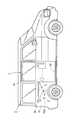
図1に示すように、ミニバンまたはワゴンタイプ等の車両のスライドドア1(以下、「ドア」と記す)は、車体2の側面に設けられた前後方向の上、中、下のガイドレール2A、2B、2Cにより前後方向へ開閉可能に支持され、手動操作及び車体2の後部内に搭載される電動式の開閉駆動装置PSDにより、車体2の側面に設けられた乗降口を閉鎖した全閉位置から車体2の外側面より若干外方に移動しつつ車体2の側面に沿って後方へ移動した全開位置及びその逆へ移動可能である。なお、図1以外に示す駆動ユニット3は、左ドア用であって、車体2における左側面のパネル内に配置される。  As shown in FIG. 1, a slide door 1 (hereinafter referred to as “door”) of a vehicle such as a minivan or a wagon type is provided withguide rails 2 </ b> A in the front, rear, and upper, middle and lower directions provided on the side surface of thevehicle body 2. A fully closed position in which the doorway provided on the side surface of thevehicle body 2 is closed by a manual operation and an electric opening / closing drive device PSD mounted in the rear part of thevehicle body 2 and supported by thedoors 2B and 2C. From the outer side of thevehicle body 2 to the fully open position moved backward along the side surface of thevehicle body 2 and vice versa. Thedrive unit 3 other than that shown in FIG. 1 is for the left door and is disposed in the left side panel of thevehicle body 2.

ドア開閉駆動装置PSDは、車体2に取り付けられる駆動ユニット3と、駆動ユニット3が出力する動力をドア1に伝達するためのボーデンケーブル等により形成される開用ケーブル10及び閉用ケーブル11とを含む。  The door opening / closing drive device PSD includes adrive unit 3 attached to thevehicle body 2, and anopening cable 10 and aclosing cable 11 formed by a Bowden cable or the like for transmitting power output from thedrive unit 3 to thedoor 1. Including.

図2、3に示すように、駆動ユニット3は、車体2に固定される合成樹脂製の第1ハウジング5及び第1ハウジング5と別体で形成される合成樹脂製の第2ハウジング6を含むハウジング4と、正逆回転可能なモータ7と、ハウジング4内に車内外方向を向く枢軸8により回転自在に枢支されモータ7の回転を減速して回転可能な減速ギヤを形成するウォームホイール9と、枢軸8により回転自在に枢支され、開用ケーブル10及び閉用ケーブル11が巻回されて連結される回転ドラム12と、ウォームホイール9と回転ドラム12間の動力伝達経路を断続可能な電磁クラッチ13と、開用ケーブル10及び閉用ケーブル11に対して所定の張力を付与する開、閉用テンショナー14、15を備える。なお、第2ハウジング6は、自体の車外側(図2、3において下側)を閉塞するための合成樹脂製のカバー16を含む。  As shown in FIGS. 2 and 3, thedrive unit 3 includes a synthetic resinfirst housing 5 fixed to thevehicle body 2 and a synthetic resinsecond housing 6 formed separately from thefirst housing 5. Thehousing 4, amotor 7 capable of rotating in the forward and reverse directions, and aworm wheel 9 that is rotatably supported by apivot 8 that faces the inside and outside of thevehicle 4 to reduce the rotation of themotor 7 to form a rotatable reduction gear. And arotary drum 12 that is pivotally supported by apivot 8 and is wound and connected with anopening cable 10 and aclosing cable 11, and a power transmission path between theworm wheel 9 and therotary drum 12 can be interrupted. Theelectromagnetic clutch 13 is provided with opening andclosing tensioners 14 and 15 for applying a predetermined tension to theopening cable 10 and theclosing cable 11. Thesecond housing 6 includes acover 16 made of synthetic resin for closing the outside of the vehicle (the lower side in FIGS. 2 and 3).

ハウジング4は、第2ハウジング6を第1ハウジング5に固定した状態において、主に図4に明示されるように、枢軸8の軸線方向から見た正面視において、頂点Aにおける内角θがほぼ270度、すなわち外角がほぼ直角の角度で、頂点Aを端点に持つ二つの辺B、Cのうち辺Bに連続してほぼ直角な辺Dと、辺Bに対向して平行で、かつ辺Dに連続して直角な辺Eと、頂点Aを端点に持つ二つの辺B、Cのうち辺Cに連続して直角な辺Fと、辺Cに対向して平行で、かつ辺Fに連続して直角な辺Gと、辺Eの端点と辺Gの端点との間にあって、辺E及び辺Gに対して内角がほぼ135度となる辺Hとを有し、全体の外観外形がほぼL字型(多角形形状)に形成される。  In the state where thesecond housing 6 is fixed to thefirst housing 5, thehousing 4 has an inner angle θ at the apex A of about 270 in a front view as viewed from the axial direction of thepivot 8 as mainly shown in FIG. 4. Of the two sides B and C having an apex A as an end point, the side D that is substantially perpendicular to the side B and parallel to the side B and parallel to the side B, and the side D Of the two sides B and C having the vertex A as an end point, the side F continuously perpendicular to the side C, parallel to the side C, and continuous to the side F A side G that is perpendicular to each other and a side H that is between the end point of the side E and the end point of the side G and that has an inner angle of about 135 degrees with respect to the side E and the side G. It is formed in an L shape (polygon shape).

なお、第1ハウジング5は、図5に示すように、頂点A、内角θ及び辺B〜Hを有する形状、すなわち正面視においてハウジング4の外形とほぼ同一形状であるのに対し、第2ハウジング6は、図6に示すように、前下部(図4において左下部、図6において右下部)が上方へ湾曲した形状であるため、頂点A、内角θ及び辺B〜Fを有するが、辺G、Hを有しない形状である。よって、第1、2ハウジング5、6の頂点A、内角θ及び各辺B〜Fを、ハウジング4の頂点A、内角θ及び辺B〜Fと同意語とし、第1ハウジング5の辺G、Hを、ハウジング4の辺G、Hと同意語とする。  As shown in FIG. 5, thefirst housing 5 has a shape having an apex A, an inner angle θ, and sides B to H, that is, substantially the same shape as the outer shape of thehousing 4 in a front view. 6, since the front lower part (the lower left part in FIG. 4 and the lower right part in FIG. 6) is curved upward as shown in FIG. 6, it has a vertex A, an interior angle θ, and sides B to F. The shape does not have G and H. Therefore, the vertex A, the inner angle θ and the sides B to F of the first andsecond housings 5 and 6 are synonymous with the vertex A, the inner angle θ and the sides B to F of thehousing 4, and the side G of thefirst housing 5, Let H be a synonym for sides G and H of thehousing 4.

第1ハウジング5は、駆動ユニット3を車体2の被取付部に取り付けた状態で垂直方向の面を有する基部51と、基部51のほぼ中央部にあって枢軸8が貫通する円形孔52と、基部51における円形孔52の周辺にあって電磁クラッチ13の端部が若干埋設可能な円形凹部53と、自体の外形部分にあって外方へ突出した複数(3個)のハウジング用取付部54とを一体形成する。  Thefirst housing 5 includes abase 51 having a vertical surface in a state where thedrive unit 3 is attached to the mounted portion of thevehicle body 2, acircular hole 52 through which thepivot 8 is located substantially at the center of thebase 51, Acircular recess 53 around thecircular hole 52 in thebase 51 where the end of theelectromagnetic clutch 13 can be slightly embedded, and a plurality of (three)housing mounting portions 54 in the outer shape of thebase 51 and projecting outward. And are integrally formed.

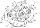
各ハウジング取付部54は、車体2の被取付部に車外方向を向く取付用ボルト27により直接固定可能である。また、駆動ユニット3を他の車種に取り付ける場合には、各ハウジング取付部54には、他の車種の車体の被取付部に対応する固定部283を形成した図11、12に示すような取付ブラケット28または図13、14に示すような固定部293を形成した他の取付ブラケット29が取付用ボルト27により選択的に固定される。これにより、駆動ユニット3を取り付ける車種の被取付部に応じて、ハウジング4の各ハウジング取付部54を車体2の被取付部に直接固定するか、取付ブラケット28または29のいずれかを第1ハウジング5の各ハウジング取付部54に選択的に固定することによって、異なる車種間においてハウジング4の特に第1ハウジング5、ひいては駆動ユニット3の共用化が可能となる。なお、各取付ブラケット28を各ハウジング取付部54に固定した場合には、取付ブラケット28の固定部283をボルト(図示略)により被取付部に固定し、また、他の取付ブラケット29をハウジング取付部54に固定した場合には、他の取付ブラケット29の固定部293をボルト(図示略)により被取付部に固定する。  Eachhousing mounting portion 54 can be directly fixed to the mounted portion of thevehicle body 2 by mountingbolts 27 facing outward from the vehicle. When thedrive unit 3 is attached to another vehicle type, eachhousing attachment portion 54 is provided with afixing portion 283 corresponding to the attachment portion of the vehicle body of the other vehicle type as shown in FIGS. Thebracket 28 or anothermounting bracket 29 having afixing portion 293 as shown in FIGS. 13 and 14 is selectively fixed by themounting bolts 27. Thereby, according to the to-be-attached part of the vehicle model which attaches thedrive unit 3, eachhousing attaching part 54 of thehousing 4 is directly fixed to the to-be-attached part of thevehicle body 2, or either theattachment bracket 28 or 29 is attached to the first housing. By selectively fixing to the respectivehousing mounting portions 54, it is possible to share thehousing 4, particularly thefirst housing 5, and thus thedrive unit 3, among different vehicle types. When eachmounting bracket 28 is fixed to eachhousing mounting portion 54, thefixing portion 283 of themounting bracket 28 is fixed to the mounted portion with a bolt (not shown), and theother mounting bracket 29 is mounted to the housing. When fixed to theportion 54, thefixing portion 293 of theother mounting bracket 29 is fixed to the mounted portion with a bolt (not shown).

好ましくは、各ハウジング取付部54には、取付用ボルト27及び取付ブラケット28、29の固定部283、293を被取付部に固定するためのボルト(図示略)が、螺合可能な雌ねじ孔241を有するナット24がインサート成形される。  Preferably, eachhousing mounting portion 54 has afemale screw hole 241 into which a bolt (not shown) for fixing themounting bolt 27 and thefixing portions 283 and 293 of themounting brackets 28 and 29 to the mounted portion can be screwed. Anut 24 having inserts is insert molded.

さらに、第1ハウジング5における各ハウジング取付部54の近傍には、雌ねじ孔241の開口方向と同一方向へ向けて陥没し、取付ブラケット28、29に折曲形成された図12、14に示す折曲片281、291が差し込み可能なスリット形状の嵌合溝55がそれぞれ設けられる。さらに、嵌合溝55の奥側には、各折曲片281、291に形成した開口部282、292が各折曲片281、291の抜け方向に係合可能な爪部58が形成される。これにより、各ブラケット28、29を必要に応じて、各ハウジング取付部54に取付用ボルト27と共に強固に固定することができる。  Further, in the vicinity of eachhousing mounting portion 54 in thefirst housing 5, it is recessed in the same direction as the opening direction of thefemale screw hole 241, and the folding shown in FIGS. A slit-likefitting groove 55 into which thecurved pieces 281 and 291 can be inserted is provided. Further, on the back side of thefitting groove 55, aclaw portion 58 is formed in which theopenings 282 and 292 formed in thebent pieces 281 and 291 can be engaged in the removal direction of thebent pieces 281 and 291. . Thereby, eachbracket 28 and 29 can be firmly fixed to eachhousing attachment part 54 with the attachment volt | bolt 27 as needed.

図4、5に示すように、モータ7は、そのアーマチュアの軸線方向Oが辺B及び開用ケーブル10の軸線方向、すなわち導出方向X1に対して直角で、かつ辺C及び閉用ケーブル11の軸線方向、すなわち導出方向X2に対して平行になるように、第1ハウジング5の辺Bを形成する取付面に固定される。これにより、モータ7をハウジング4に取り付けた形態において、モータ7の一部、具体的には50パーセント以上の範囲は、正面視において、辺B及びCと、辺Dを延長した延長線D1と、辺Fを延長した延長線F1とで囲まれる矩形範囲内に収まる。この結果、モータ7がハウジング4の辺D、Fから外方へ大きく突出しない形状、すなわち正面視において全体的にほぼ矩形となるため、駆動ユニット3の車体2に対する取付占有面積を最小限として、車体2に取り付けられる他の部品のレイアウトに対して悪影響を与えることを抑止し、また駆動ユニット3の輸送時には、駆動ユニット3が嵩張らない形態で効率的に搬送することができる。好ましくは、モータ7は、少なくともアーマチュアの軸方向Oの端部が、ハウジング取付部54の外端に接する線で、かつ延長線F1に平行な線F2よりも外方へ突出しないようにする。さらに、好ましくは、モータ7の軸方向の寸法を短縮するか、または辺B、Cを若干延長することで、モータ7の全体を前記矩形範囲内に収まるようにする。  As shown in FIGS. 4 and 5, themotor 7 has an armature axial direction O that is perpendicular to the side B and the axial direction of theopening cable 10, that is, the lead-outdirection X 1, and the side C and theclosing cable 11. Thefirst housing 5 is fixed to the mounting surface forming the side B so as to be parallel to the axial direction, that is, the derivation direction X2. Thereby, in the form in which themotor 7 is attached to thehousing 4, a part of themotor 7, specifically, a range of 50% or more includes the sides B and C and the extension line D <b> 1 extending the side D in the front view. , It falls within a rectangular range surrounded by an extension line F1 extending from the side F. As a result, themotor 7 has a shape that does not protrude outward from the sides D and F of thehousing 4, that is, a substantially rectangular shape in front view, so that the mounting occupation area of thedrive unit 3 with respect to thevehicle body 2 is minimized. An adverse effect on the layout of other components attached to thevehicle body 2 can be suppressed, and when thedrive unit 3 is transported, thedrive unit 3 can be efficiently transported without being bulky. Preferably, themotor 7 prevents at least the end portion in the axial direction O of the armature from projecting outward beyond the line F2 that is in contact with the outer end of thehousing mounting portion 54 and parallel to the extension line F1. Further, preferably, the dimension of themotor 7 in the axial direction is shortened or the sides B and C are slightly extended so that theentire motor 7 is within the rectangular range.

第1ハウジング5の基部51とカバー16間の収容空間には、枢軸8により回転可能に枢支されるウォームホイール9と、枢軸8と一体的に回転可能に枢支される回転板18と、第1ハウジング5に固定されるウォームホイールカバー19と、第1ハウジング5に固定されて各種プリント配線が施された電装基板17とが設けられる。  In the accommodation space between the base 51 of thefirst housing 5 and thecover 16, aworm wheel 9 that is rotatably supported by thepivot 8, a rotatingplate 18 that is pivotally supported integrally with thepivot 8, Aworm wheel cover 19 fixed to thefirst housing 5 and anelectrical board 17 fixed to thefirst housing 5 and provided with various printed wirings are provided.

ウォームホイール9は、モータ7の回転軸に止着されたウォーム(図示略)に噛合し、モータ7の動力により回転する。回転ドラム12の回転は、電装基板17の実装面に実装された回転検出センサ171が枢軸8を介して回転ドラム12と一体的に回転可能な回転板18の回転を検出することで検出される。回転板18の回転を検出した回転検出センサ171の検出信号は、電装基板17に実装されるコネクタ172に各種信号を送信可能な各種電線を接続することで、車体2の適所に設けられる制御回路装置(図示略)に送信される。制御回路装置は、検出信号に基づいて、ドア1の移動方向及び位置を演算する。なお、コネクタ172には、モータ7及び電磁クラッチ13に電力を供給するための電源線も接続される。  Theworm wheel 9 meshes with a worm (not shown) fixed to the rotation shaft of themotor 7, and rotates by the power of themotor 7. The rotation of therotary drum 12 is detected when therotation detection sensor 171 mounted on the mounting surface of theelectrical board 17 detects the rotation of therotary plate 18 that can rotate integrally with therotary drum 12 via thepivot 8. . A detection signal of therotation detection sensor 171 that detects the rotation of therotating plate 18 is connected to aconnector 172 mounted on theelectrical board 17 by connecting various electric wires capable of transmitting various signals, thereby providing a control circuit provided at an appropriate position of thevehicle body 2. It is transmitted to a device (not shown). The control circuit device calculates the moving direction and position of thedoor 1 based on the detection signal. Theconnector 172 is also connected to a power line for supplying power to themotor 7 and theelectromagnetic clutch 13.

第1ハウジング5における基部51の第2ハウジング6に対向する側の面には、電磁クラッチ13が配置される。電磁クラッチ13は、回転ドラム12の内側に収容されると共に、電磁コイルが組み込まれて基部51に固定される磁性体からなるほぼ円筒状のフィールドコア20と、フィールドコア20の中央部を貫通する枢軸8により回転可能に枢支されフィールドコア20の外周に遊嵌されるロータ21と、ロータ21の摩擦面に対向して枢軸8に軸方向へ僅かに摺動し得るように遊嵌されるアーマチュア22とを備える。  Theelectromagnetic clutch 13 is disposed on the surface of the base 51 in thefirst housing 5 on the side facing thesecond housing 6. Theelectromagnetic clutch 13 is housed inside therotary drum 12 and penetrates through a substantiallycylindrical field core 20 made of a magnetic body in which an electromagnetic coil is incorporated and fixed to thebase 51, and the center of thefield core 20. Arotor 21 rotatably supported by thepivot 8 and loosely fitted on the outer periphery of thefield core 20, and is loosely fitted to thepivot 8 so as to be slightly slidable in the axial direction so as to face the friction surface of therotor 21.Armature 22.

フィールドコア20は、第1ハウジング5の円形凹部53に固定される。ロータ21は、磁性体から形成され、フィールドコア20の外周を覆うと共に、摩擦面(図9、10において上面)に対して反対側へ向けて突出し、枢軸8に回転自在に外嵌される軸受筒部211を有している。軸受筒部211は、枢軸8と共にフィールドコア20の中心及び第1ハウジング5の円形孔52を貫通し、その端部がウォームホイール9の中心に形成された中心孔91に嵌合する。これにより、ウォームホイール9及びロータ21は、枢軸8を中心に互いに一体的に回転する。  Thefield core 20 is fixed to thecircular recess 53 of thefirst housing 5. Therotor 21 is made of a magnetic material, covers the outer periphery of thefield core 20, protrudes toward the opposite side with respect to the friction surface (the upper surface in FIGS. 9 and 10), and is a bearing that is rotatably fitted to thepivot 8. Acylindrical portion 211 is provided. The bearingtube portion 211 passes through the center of thefield core 20 and thecircular hole 52 of thefirst housing 5 together with thepivot 8, and its end portion is fitted into acenter hole 91 formed at the center of theworm wheel 9. Thereby, theworm wheel 9 and therotor 21 rotate integrally with each other about thepivot 8.

アーマチュア22は、回転ドラム12の内側に枢軸8の軸方向へ僅かに移動可能に遊嵌されると共に、回転ドラム12と一体的に回転し得るように、外周に形成された複数の係合凸部221が回転ドラム12の内周面に形成された複数の係合凹部121に対してそれぞれ回転方向に係合する。  Thearmature 22 is loosely fitted inside therotary drum 12 so as to be slightly movable in the axial direction of thepivot shaft 8, and a plurality of engaging projections formed on the outer periphery so as to rotate integrally with therotary drum 12. Theportions 221 engage with the plurality of engagingrecesses 121 formed on the inner peripheral surface of therotating drum 12 in the rotational direction.

枢軸8の軸方向におけるロータ21とアーマチュア22間には、ウェーブワッシャ25が介在されている。このウェーブワッシャ25は、ロータ21の回転面に凹設された環状溝222に設置され、アーマチュア22の摩擦面がロータ21の摩擦面から離れる方向へ付勢する。  Awave washer 25 is interposed between therotor 21 and thearmature 22 in the axial direction of thepivot 8. Thewave washer 25 is installed in anannular groove 222 recessed in the rotating surface of therotor 21, and biases the friction surface of thearmature 22 in a direction away from the friction surface of therotor 21.

枢軸8は、第1ハウジング5に設けられるボールベアリング31、及び第2ハウジング6に設けられるボールベアリング32によりハウジング4内に回転可能に枢支されると共に、車内側を向く端面には、雌ねじ孔81が設けられ、同じく端部には、鍔部82が設けられ、また、車外側寄りの端部には、Eワッシャー33が嵌合される環状溝83が設けられる。これにより、主に図9、10に示されるように、ウォームホイール9及び電磁クラッチ13は、枢軸8における鍔部82と環状溝83に嵌合されたEワッシャー33との間に挟み込まれて支持される。  Thepivot 8 is rotatably supported in thehousing 4 by aball bearing 31 provided in thefirst housing 5 and aball bearing 32 provided in thesecond housing 6, and a female screw hole is provided on an end surface facing the vehicle interior. 81 is provided, and aflange 82 is provided at the end, and anannular groove 83 into which theE washer 33 is fitted is provided at the end near the vehicle exterior. 9 and 10, theworm wheel 9 and the electromagnetic clutch 13 are supported by being sandwiched between theflange portion 82 of thepivot 8 and theE washer 33 fitted in theannular groove 83. Is done.

電磁クラッチ13への非通電時、すなわち切断状態においては、モータ7の動力によりウォームホイール9が回転しても、ロータ21とアーマチュア22とが互いに切断されているため、モータ7の動力は、回転ドラム12に伝達されない。また、電磁クラッチ13の通電時、すなわち接続状態においては、アーマチュア22がロータ21の摩擦面に磁力により吸着されて、ロータ21とアーマチュア22とが互いに接続されるため、モータ7の動力は、ウォームホイール9、ロータ21、アーマチュア22を介して、回転ドラム12に伝達される。  When theelectromagnetic clutch 13 is not energized, that is, in a disconnected state, even if theworm wheel 9 is rotated by the power of themotor 7, therotor 21 and thearmature 22 are disconnected from each other. It is not transmitted to thedrum 12. Further, when theelectromagnetic clutch 13 is energized, that is, in the connected state, thearmature 22 is attracted to the friction surface of therotor 21 by a magnetic force, and therotor 21 and thearmature 22 are connected to each other. It is transmitted to therotating drum 12 via thewheel 9, therotor 21, and thearmature 22.

なお、以下に使用する「主動側サブアッセンブリ−」とは、モータ7、枢軸8、ウォームホイール9、電磁クラッチ13及び電装基板17を第1ハウジング5に組み付けた状態と定義し、「従動側サブアッセンブリー」とは、回転ドラム12、各テンショナー14、15及び各ケーブル10、11を第2ハウジング6に組み付けた状態と定義する。なお、電磁クラッチ13、電装基板17及び各テンショナー14、15は、車種に対応させるため必要に応じて省略される場合もある。  The “primary drive side subassembly” used below is defined as a state in which themotor 7, thepivot 8, theworm wheel 9, the electromagnetic clutch 13, and theelectrical board 17 are assembled to thefirst housing 5. “Assembly” is defined as a state in which therotary drum 12, thetensioners 14 and 15, and thecables 10 and 11 are assembled to thesecond housing 6. The electromagnetic clutch 13, theelectrical board 17, and thetensioners 14 and 15 may be omitted as necessary to correspond to the vehicle type.

第2ハウジング6は、第1ハウジング5の各嵌合溝55の近傍及び他の1カ所にボルト23により固定されると共に、回転ドラム12を回転可能に収容するための有底円筒状のドラム収容部61と、開、閉テンショナー14、15を収容するためのテンショナー収容部62、63とを一体形成する。  Thesecond housing 6 is fixed by abolt 23 in the vicinity of eachfitting groove 55 of thefirst housing 5 and at one other place, and a bottomed cylindrical drum housing for rotatably housing therotating drum 12. Theportion 61 and tensioneraccommodating portions 62 and 63 for accommodating the open andclosed tensioners 14 and 15 are integrally formed.

回転ドラム12は、ドラム収容部61内に枢軸8により回転自在に枢支されると共に、枢軸8における鍔部82と端面に設けられた雌ねじ孔81に螺合するボルト26との間に締結固定される。なお、ボルト26は、従動側サブアッセンブリーを主動側サブアッセンブリーに組み付けた後、第2ハウジング6のほぼ中央部に設けられた円形孔69から回転ドラム12の中心に設けられた中心孔123を通して枢軸8の雌ねじ孔81に螺合される。また、回転ドラム12の外周面には、各ケーブル10、11のインナーケーブル102、112が巻回される螺旋溝122が形成される。  Therotary drum 12 is rotatably supported in thedrum housing 61 by thepivot 8 and is fastened and fixed between theflange 82 of thepivot 8 and thebolt 26 screwed into thefemale screw hole 81 provided on the end surface. Is done. Thebolt 26 is pivoted from thecircular hole 69 provided in the substantially central portion of thesecond housing 6 through thecenter hole 123 provided in the center of therotary drum 12 after the driven side subassembly is assembled to the main driving side subassembly. 8 is threaded into thefemale screw hole 81. Aspiral groove 122 around which theinner cables 102 and 112 of thecables 10 and 11 are wound is formed on the outer peripheral surface of therotary drum 12.

上述のように、回転ドラム12がハウジング4内に回転可能に枢支されることによって、電磁クラッチ13が接続状態の場合、モータ7の動力は、ウォームホイール9、ロータ21及びアーマチュア22を介して回転ドラム12に伝達され、回転ドラム12は、枢軸8と共に回転する。  As described above, when the rotary clutch 12 is pivotally supported in thehousing 4 and theelectromagnetic clutch 13 is in the connected state, the power of themotor 7 is transmitted via theworm wheel 9, therotor 21 and thearmature 22. Therotation drum 12 rotates with thepivot 8.

第2ハウジング6には、従動側サブアッセンブリーを主動側サブアッセンブリーに組み付ける際の最終組立て行程において、ドラム収容部61内に組み付けられた回転ドラム12がドラム収容部61から脱落しないように、回転ドラム12をドラム収容部61内に仮保持するための2個の外側に弾性変形可能な保持片64と、各テンショナー収容部62、63内に組み付けられた各テンショナー14、15が各テンショナー収容部62、63から脱落しないように、各テンショナー14、15を各テンショナー収容部62、63内に仮保持するための保持片65、66と、回転ドラム12に巻回された各ケーブル10、11を第2ハウジング6外へ導出させるためのケーブル導出部67、68とが形成される。なお、各保持片64は、従動側サブアッセンブリーを主動側サブアッセンブリーに組み付けた状態においては、回転ドラム12に対して接触しない。  Thesecond housing 6 is provided with a rotating drum so that therotating drum 12 assembled in thedrum housing 61 does not fall off from thedrum housing 61 in the final assembly process when the driven sub-assembly is assembled to the main driving sub-assembly. The two holdingpieces 64 that are elastically deformable to the outside for temporarily holding 12 in thedrum accommodating portion 61, and thetensioners 14 and 15 assembled in the respectivetensioner accommodating portions 62 and 63 are each tensioner accommodatingportion 62. , 63 so that thetensioners 14 and 15 are temporarily held in thetensioner receiving portions 62 and 63, and thecables 10 and 11 wound around therotary drum 12 are 2 Cable lead-outportions 67 and 68 for leading out of thehousing 6 are formed. Each holdingpiece 64 does not come into contact with therotating drum 12 in a state where the driven side subassembly is assembled to the main driving side subassembly.

各ケーブル導出部67、68は、第2ハウジング6の辺C、Bを形成する面にそれぞれ設けられる。よって、開用ケーブル10は、ハウジング4の辺C及びモータ7の軸線方向Oに対して直角で、辺Bに対して平行である導出方向X1へ向けて導出し、かつモータ7に対して交差する。閉用ケーブル11は、ハウジング4の辺Bに対して直角で、辺C及びモータ7の軸線方向Oに対して平行である導出方向X2へ向けて導出する。また、開用ケーブル10及び閉用ケーブル11は、モータ7の真横、換言するとハウジングの辺Dの延長線D1及びF1よりも内側で互い交差する。  The cable lead-outportions 67 and 68 are respectively provided on the surfaces forming the sides C and B of thesecond housing 6. Therefore, the openingcable 10 is led out in the lead-out direction X1 perpendicular to the side C of thehousing 4 and the axial direction O of themotor 7 and parallel to the side B, and intersects themotor 7. To do. The closingcable 11 is led out in a lead-out direction X2 that is perpendicular to the side B of thehousing 4 and parallel to the side C and the axial direction O of themotor 7. Further, the openingcable 10 and theclosing cable 11 cross each other directly beside themotor 7, in other words, inside the extension lines D <b> 1 and F <b> 1 of the side D of the housing.

開用テンショナー14は、第2ハウジング6のテンショナー収容部62内に辺Cに対して直角方向、換言すると開用ケーブル10の導出方向X1と平行方向へ摺動自在に保持されるコ字状のスライド部材141と、スライド部材141に車内外方向、すなわち枢軸8と平行な軸部142aにより枢支されるテンションプーリー142と、スライド部材141を介してテンションプーリー142に対して辺Cから離れる方向への付勢力を付与するコイルスプリング143とを有する。  Theopening tensioner 14 is slidably held in thetensioner accommodating portion 62 of thesecond housing 6 so as to be slidable in a direction perpendicular to the side C, in other words, parallel to the direction X1 of theopening cable 10. Theslide member 141, thetension pulley 142 pivotally supported by theslide member 141 by theshaft 142a parallel to thepivot shaft 8, and the direction away from the side C with respect to thetension pulley 142 via theslide member 141. And acoil spring 143 for applying the urging force.

第2ハウジング6におけるテンショナー収容部62に形成された各保持片65は、テンションプーリ142に当接することで、従動側サブアッセンブリーを主動側サブアッセンブリーに組み付ける際、開用テンショナー14がテンショナー収容部62から脱落しないように仮保持する。スライド部材141は、自体の車内側を向く面に突設された突部141aが第2ハウジング6に形成された長孔621に摺動自在に係合すると共に、車外側を向く面に突設された突部141bが第1ハウジング5に形成された長溝56に摺動自在に係合することによって、第1ハウジング5と第2ハウジング6間に摺動自在に支持される。なお、各保持片65は、従動側サブアッセンブリーを主動側サブアッセンブリーに組み付けた状態においては、テンションプーリー142に対して接触しない。  Each holdingpiece 65 formed in thetensioner accommodating portion 62 of thesecond housing 6 abuts on thetension pulley 142 so that theopening tensioner 14 is attached to thetensioner accommodating portion 62 when the driven side subassembly is assembled to the main driving side subassembly. Temporarily hold it so that it will not fall off. Theslide member 141 has a projectingportion 141a projecting on the surface facing the vehicle inner side slidably engages with along hole 621 formed in thesecond housing 6, and projects on the surface facing the vehicle outer side. The projectingportion 141 b is slidably engaged with thelong groove 56 formed in thefirst housing 5, so that it is slidably supported between thefirst housing 5 and thesecond housing 6. Each holdingpiece 65 does not contact thetension pulley 142 when the driven side subassembly is assembled to the main driving side subassembly.

閉用テンショナー15は、第2ハウジング6のテンショナー収容部63内に辺Bに対して直角方向、換言すると閉用ケーブル11の導出方向X2と平行方向へ摺動自在に保持されるコ字状のスライド部材151と、スライド部材151に車内外方向、すなわち枢軸8と平行な軸部152aにより枢支されるテンションプーリー152と、スライド部材151を介してテンションプーリー152に対して辺Bから離れる方向への付勢力を付与するコイルスプリング153とを有する。  Theclosing tensioner 15 is slidably held in thetensioner accommodating portion 63 of thesecond housing 6 so as to be slidable in a direction perpendicular to the side B, in other words, in a direction parallel to the lead-out direction X2 of the closingcable 11. The slidingmember 151, thetension pulley 152 pivotally supported by the slidingmember 151 by theshaft portion 152a parallel to thepivot shaft 8, and the direction away from the side B with respect to thetension pulley 152 via the slidingmember 151 And acoil spring 153 for applying the urging force.

第2ハウジング6におけるテンショナー収容部63に形成された各保持片66は、テンションプーリ152に当接することで、従動側サブアッセンブリーを主動側サブアッセンブリーに組み付ける際、閉用テンショナー15がテンショナー収容部63から脱落しないように仮保持する。スライド部材151は、自体の車内側を向く面に突設された突部151aが第2ハウジング6に形成された長孔622に摺動自在に係合すると共に、車外側を向く面に突設された突部151bが第1ハウジング5に形成された長溝57に摺動自在に係合することによって、第1ハウジング5と第2ハウジング6間に摺動自在に支持される。なお、各保持片66は、従動側サブアッセンブリーを主動側サブアッセンブリーに組み付けた状態においては、テンションプーリー152に対して接触しない。  Each holdingpiece 66 formed in thetensioner accommodating portion 63 of thesecond housing 6 abuts on thetension pulley 152, so that theclosing tensioner 15 is attached to thetensioner accommodating portion 63 when the driven side subassembly is assembled to the main driving side subassembly. Temporarily hold it so that it will not fall off. Theslide member 151 has aprotrusion 151a protruding from the surface facing the inside of the vehicle slidably engages with along hole 622 formed in thesecond housing 6 and protrudes from the surface facing the outside of the vehicle. The protrudingportion 151 b is slidably engaged with thelong groove 57 formed in thefirst housing 5, so that the protrudingportion 151 b is slidably supported between thefirst housing 5 and thesecond housing 6. Each holdingpiece 66 does not contact thetension pulley 152 when the driven side subassembly is assembled to the main driving side subassembly.

開用ケーブル10は、アウターチューブ101の端部が第2ハウジング6のケーブル導出部67に固定されると共に、アウターチューブ101内に軸線方向X1へ摺動自在に挿通されたインナーケーブル102がテンションプーリー142に掛け回した状態で回転ドラム12の螺旋溝122に巻回されて連結される。開用ケーブル11は、アウターチューブ111の端部が第2ハウジング6のケーブル導出部68に固定されると共に、アウターチューブ111内に軸線方向X2へ摺動自在に挿通されたインナーケーブル112がテンションプーリー152に掛け回した状態で回転ドラム12の螺旋溝122に巻回されて連結される。  In theopening cable 10, the end portion of theouter tube 101 is fixed to the cable lead-outportion 67 of thesecond housing 6, and theinner cable 102 slidably inserted in theaxial direction X 1 into theouter tube 101 is a tension pulley. In a state of being wound around 142, it is wound around and connected to thespiral groove 122 of therotary drum 12. The openingcable 11 has an end portion of theouter tube 111 fixed to the cable lead-outportion 68 of thesecond housing 6, and aninner cable 112 inserted into theouter tube 111 so as to be slidable in the axial direction X2 is a tension pulley. In a state of being wound around 152, it is wound around and connected to thespiral groove 122 of therotary drum 12.

第2ハウジング6から導出される各ケーブル10、11の各インナーケーブル102、112は、ガイドレール2Bの前端及び後端に設けられたガイド部材(図示略)にそれぞれ掛け回されて、ガイドレール2Bの長手方向に沿って配索されて端部がスライドドア1に連結される。  Theinner cables 102 and 112 of thecables 10 and 11 led out from thesecond housing 6 are respectively hung around guide members (not shown) provided at the front end and the rear end of theguide rail 2B, and theguide rail 2B. The end portion is connected to theslide door 1 along the longitudinal direction.

電磁クラッチ13の接続状態において、モータ7の動力により回転ドラム12が回転した場合には、開用ケーブル10または閉用ケーブル11のインナーケーブル101または112のいずれか一方が回転ドラム12の螺旋溝122に巻き込まれ、他方が送り出されることで、ドア1を開方向または閉方向へ移動させることができる。また、電磁クラッチ13の非通電時、すなわち電磁クラッチ13の切断状態においては、ロータ21とアーマチュア22との間が切断されるため、ウォームホイール9及びモータ7を逆転させることなく、ドア1を手動操作で開閉することができる。  When therotary drum 12 is rotated by the power of themotor 7 in the connected state of the electromagnetic clutch 13, either theopening cable 10 or theinner cable 101 or 112 of the closingcable 11 is connected to thespiral groove 122 of therotating drum 12. Thedoor 1 can be moved in the opening direction or the closing direction by being caught in the door and being fed out the other. Further, when theelectromagnetic clutch 13 is not energized, that is, when theelectromagnetic clutch 13 is disconnected, therotor 21 and thearmature 22 are disconnected, so that thedoor 1 is manually operated without reversing theworm wheel 9 and themotor 7. Can be opened and closed by operation.

次に、駆動ユニット3の組付要領について説明する。
先ず、図7、8、10に示すように、回転ドラム12、開用テンショナー14及び閉用テンショナー15を第2ハウジング6に組み付け、さらに、開用ケーブル10、閉用ケーブル11の各アウターチューブ101、111を第2ハウジング6の各ケーブル導出部67、68に固定すると共に、各インナーケーブル102、112を回転ドラム12の螺旋溝122に巻き付けて連結することによって、従動側サブアッセンブリーを完成させ、また、モータ7、枢軸8、ウォームホイール9、電磁クラッチ13、電装基板17及び回転板18を第1ハウジング5に組み付けることによって、主動側サブアッセンブリーを完成させる。
Next, the assembly procedure of thedrive unit 3 will be described.
First, as shown in FIGS. 7, 8, and 10, therotary drum 12, theopening tensioner 14, and theclosing tensioner 15 are assembled to thesecond housing 6, and eachouter tube 101 of theopening cable 10 and theclosing cable 11 is assembled. , 111 are fixed to the cable lead-outportions 67 and 68 of thesecond housing 6 and theinner cables 102 and 112 are wound around and connected to thespiral groove 122 of therotary drum 12, thereby completing the driven sub-assembly. Further, themotor 7, thepivot 8, theworm wheel 9, the electromagnetic clutch 13, theelectrical component board 17, and therotating plate 18 are assembled to thefirst housing 5 to complete the main driving side sub-assembly.

次に、最終組立て行程において、従動側サブアッセンブリーを、枢軸8の軸線方向から回転ドラム12が電磁クラッチ13に被さるようにして主動側サブアッセンブリーに載せて、第2ハウジング6を複数のボルト23により第1ハウジング5に固定すると共に、第2ハウジング6の円形孔69から覗いた枢軸8の雌ねじ孔81にボルト26を螺合して、回転ドラム12を枢軸8に連結することで、主動側サブアッセンブリーと従動側サブアッセンブリーとを互いに結合して、駆動ユニット3の組立ては完成する。  Next, in the final assembly process, the driven side subassembly is placed on the main driving side subassembly so that therotary drum 12 covers the electromagnetic clutch 13 from the axial direction of thepivot 8, and thesecond housing 6 is mounted by the plurality ofbolts 23. While fixing to the1st housing 5 and screwing the volt |bolt 26 to theinternal thread hole 81 of thepivot 8 looked from thecircular hole 69 of the2nd housing 6, and connecting therotating drum 12 to thepivot 8, the main drive side sub The assembly of thedrive unit 3 is completed by coupling the assembly and the driven sub-assembly together.

最終組立て行程を行う際、第2ハウジング6に組み付けられた回転ドラム12及び各テンショナー14、15は、保持片64及び65、66により仮保持されて第2ハウジング6から脱落したり外れたりする虞がないため、従動側サブアッセンブリーを摺動側サブアッセンブリーに効率的に結合することができる。  During the final assembly process, therotary drum 12 and thetensioners 14 and 15 assembled in thesecond housing 6 are temporarily held by the holdingpieces 64 and 65 and 66 and may fall off or come off from thesecond housing 6. Therefore, the driven side subassembly can be efficiently coupled to the sliding side subassembly.

以上により、本実施形態においては、回転ドラム12、各テンショナー14、15及び各ケーブル10、11を第2ハウジング6に組み付けた従動側サブアッセンブリーと、モータ7、枢軸8、ウォームホイール9及び電磁クラッチ13を第1ハウジング5に組み付けた主動側サブアッセンブリーとを分離構成したことによって、例えば、異なる車種間で各ケーブル10、11のレイアウトがそれぞれ異なるタイプの摺動側サブアッセンブリーを選択的に主動側アッセンブリーに組み替え可能となるため、車種に対応する形態の従動側サブアッセンブリーを主動側サブアッセンブリーに組み替えるだけで、異なる車種間で、主動側サブアッセンブリーの共用化が可能となり、コスト低減を図ることができる。  As described above, in this embodiment, the driven sub-assembly in which therotary drum 12, thetensioners 14 and 15 and thecables 10 and 11 are assembled to thesecond housing 6, themotor 7, thepivot 8, theworm wheel 9, and the electromagnetic clutch. 13 is separated from the main drive side subassembly assembled to thefirst housing 5, for example, the slide side subassemblies of different types in which the layouts of thecables 10 and 11 are different between different vehicle types are selectively set on the main drive side. Since it can be reassembled into an assembly, it is possible to share the main drive side sub-assembly between different vehicle models by simply replacing the driven side subassembly with a configuration corresponding to the vehicle type into the main drive side subassembly, thereby reducing costs. it can.

さらには、ハウジング4を、枢軸8の軸線方向から見た正面視において、少なくとも1つの頂点Aにおける外角がほぼ直角であるほぼL字型の多角形状とし、さらにモータ7を、そのアーマチュアの軸方向がハウジング4の頂点Aを端点に持つ二つの辺B、Cのうち辺Bに対して直角となるように、ハウジング4に取り付けたことによって、主に図4に明示されるように、正面視において、駆動ユニット3の外観形状は、矩形状にすることが可能となる。このように、駆動ユニット3の外観形状をほぼ矩形状とすることで、駆動ユニット3の取付占有面積の省スペース化、及び駆動ユニット3の効率的な輸送を可能にする。  Furthermore, thehousing 4 has a substantially L-shaped polygonal shape in which the outer angle at at least one vertex A is substantially a right angle when viewed from the axial direction of thepivot 8, and themotor 7 is arranged in the axial direction of the armature. Is attached to thehousing 4 so as to be perpendicular to the side B out of the two sides B and C having the apex A of thehousing 4 as an end point, as mainly shown in FIG. The external shape of thedrive unit 3 can be made rectangular. Thus, by making the external shape of thedrive unit 3 substantially rectangular, it is possible to save the installation area of thedrive unit 3 and efficiently transport thedrive unit 3.

さらには、各ハウジング取付部54を、車体2の被取付部に取付用ボルト27により直接固定可能であり、また駆動ユニット3を他の車種に搭載する場合には、各ハウジング取付部54に取付ブラケット28または29を選択的に固定可能であるため、駆動ユニット3が搭載される車種の被取付部に応じて、ハウジング4を被取付部に直接固定するか、取付ブラケット29または30を選択的に固定することによって、異なる車種間においてハウジング4における第1ハウジング5の共用化を可能にする。  Furthermore, eachhousing mounting portion 54 can be directly fixed to the mounted portion of thevehicle body 2 with mountingbolts 27, and when thedrive unit 3 is mounted on another vehicle type, it is mounted on eachhousing mounting portion 54. Since thebracket 28 or 29 can be selectively fixed, thehousing 4 is directly fixed to the mounted portion or the mountingbracket 29 or 30 is selectively selected according to the mounted portion of the vehicle type on which thedrive unit 3 is mounted. Thefirst housing 5 in thehousing 4 can be shared between different vehicle types.

以上、本発明の実施形態について説明したが、本発明の要旨を逸脱しない範囲内で、次のような種々の変形や変更を施すことが可能である。
(1)駆動ユニット3をドア1の被取付部に取り付ける。
(2)モータ7をハウジング4の辺Cに対向するように取り付ける。
(3)開用ケーブル10を、正面視において、ハウジング4の辺Bからモータ7の軸線方向Oに対して平行方向へ導出させ、閉用ケーブル11を、正面において、ハウジング4の辺Cからモータ7の軸線方向に対して直角方向へ導出させる。
(4)ドア1を、スライドドアに代えて、スイング式のドア、または車体の後部に設けられるバックドアとする。
The embodiment of the present invention has been described above, but various modifications and changes such as the following can be made without departing from the scope of the present invention.
(1) Thedrive unit 3 is attached to the attached portion of thedoor 1.
(2) Themotor 7 is mounted so as to face the side C of thehousing 4.
(3) Theopening cable 10 is led out in a direction parallel to the axial direction O of themotor 7 from the side B of thehousing 4 in a front view, and theclosing cable 11 is connected to the motor from the side C of thehousing 4 in the front. 7 is derived in a direction perpendicular to the axial direction of 7.
(4) Instead of the slide door, thedoor 1 is a swing-type door or a back door provided at the rear part of the vehicle body.

PSD ドア開閉駆動装置
1 スライドドア
2 車体
2A、2B、2C ガイドレール
3 駆動ユニット
4 ハウジング
5 第1ハウジング
6 第2ハウジング
7 モータ
8 枢軸
9 ウォームホイール(減速ギヤ)
10 開用ケーブル
11 閉用ケーブル
12 回転ドラム
13 電磁クラッチ
14 開用テンショナー
15 閉用テンショナー
16 カバー
17 電装基板
18 回転板
19 ウォームホイールカバー
20 フィールドコア
21 ロータ
22 アーマチュア
23 ボルト
24 ナット
25 ウェーブワッシャ
26 ボルト
27 取付用ボルト
28、29 取付ブラケット
31、32 ボールベアリング
33 Eワッシャー
51 基部
52 円形孔
53 円形凹部
54 ハウジング取付部
55 嵌合溝
56、57 長溝
58 爪部
61 ドラム収容部
62、63 テンショナー収容部
64 保持片
65、66 保持片
67、68 ケーブル導出部
69 円形孔
81 雌ねじ孔
82 鍔部
83 環状溝
91 中心孔
101 アウターチューブ
102 インナーケーブル
111 アウターチューブ
112 インナーケーブル
121 係合凹部
122 螺旋溝
123 中心孔
141 スライド部材
141a、141b 突部
142 テンションプーリー
142a 軸部
143 コイルスプリング
151 スライド部材
151a、151b 突部
152 テンションプーリー
152a 軸部
153 コイルスプリング
171 回転検出センサ
172 コネクタ
211 軸受筒部
222 環状溝
221 係合凸部
241 雌ねじ孔
281、291 折曲片
282、292 開口部
621、622 長孔
PSD door opening /closing drive device 1slide door 2vehicle bodies 2A, 2B,2C guide rail 3drive unit 4housing 5first housing 6second housing 7motor 8pivot 9 worm wheel (reduction gear)
DESCRIPTION OFSYMBOLS 10Opening cable 11Closing cable 12Rotating drum 13 Electromagnetic clutch 14Opening tensioner 15Closing tensioner 16Cover 17Electrical board 18Rotating plate 19 Worm wheel cover 20Field core 21Rotor 22Armature 23Bolt 24Nut 25Wave washer 26Bolt 27 Mountingbolts 28, 29Mounting bracket 31, 32 Ball bearing 33E Washer 51Base 52Circular hole 53Circular recess 54 Housing mounting 55Fitting groove 56, 57Long groove 58Claw 61Drum housing 62, 63Tensioner housing 64Holding pieces 65, 66Holding pieces 67, 68 Cable lead-outpart 69Circular hole 81 Female threadedhole 82Gutter part 83Annular groove 91Center hole 101Outer tube 102Inner cable 111Outer tube 112 Inn -Cable 121Engaging recess 122Spiral groove 123Center hole 141Slide member 141a,141b Projection 142Tension pulley 142aShaft 143Coil spring 151Slide member 151a,151b Projection 152Tension pulley 152aShaft 153Coil spring 171Rotation detection sensor 172Connector 211Bearing cylinder part 222Annular groove 221 Engagingconvex part 241Female thread hole 281, 291Bending piece 282, 292Opening part 621, 622 Long hole

Claims (3)

Translated fromJapanese
ドアをモータの動力により開閉移動させるための車両用ドアの開閉駆動装置において、
第1ハウジングに、前記モータと、枢軸により枢支され、前記モータの回転を減速する減速歯車とを組み付けた主動側サブアッセンブリーと、
前記第1ハウジングと分離形成される第2ハウジングに、前記枢軸により枢支され、前記減速歯車と共に回転可能な回転ドラムと、前記回転ドラムに巻回されて連結されると共に、前記第2ハウジングから導出した一端が前記ドアに連結されるケーブルとを組み付けた従動側サブアッセンブリーとを備え、
前記主動側サブアッセンブリー及び前記従動側サブアッセンブリーは互いに分離構成され、前記従動側サブアッセンブリーを、前記主動側サブアッセンブリーに対して、前記枢軸の軸方向から組付可能としたことを特徴とする車両用ドアの開閉駆動装置。
In a vehicle door opening / closing drive device for opening and closing a door by the power of a motor,
A main drive side subassembly in which the motor and a reduction gear which is pivotally supported by a pivot and decelerates rotation of the motor are assembled to the first housing;
The second housing separated from the first housing is pivotally supported by the pivot shaft and rotatable together with the reduction gear, and is wound around the rotary drum and connected to the second housing. A driven side sub-assembly assembled with a cable connected to the door at one end that is led out,
The main driving side subassembly and the driven side subassembly are separated from each other, and the driven side subassembly can be assembled to the main driving side subassembly from the axial direction of the pivot. Door opening and closing drive device.
前記第2ハウジングは、前記従動側サブアッセンブリーを前記主動側サブアッセンブリーに組み付ける際、前記第2ハウジングに組み付けられた前記回転ドラムの前記第2ハウジングからの脱落を阻止可能な保持片を有することを特徴とする請求項1記載の車両用ドアの開閉駆動装置。  The second housing has a holding piece capable of preventing the rotating drum assembled to the second housing from falling off from the second housing when the driven sub-assembly is assembled to the main driving sub-assembly. The opening / closing drive device for a vehicle door according to claim 1. 前記従動側サブアッセンブリーは、前記第2ハウジングに、さらに前記ケーブルに張力を付与可能なテンショナーを組み付けた状態のものであって、
前記第2ハウジングは、前記従動側サブアッセンブリーを前記主動側サブアッセンブリーに組み付ける際、前記第2ハウジングに組み付けられた前記テンショナーの前記第2ハウジングからの脱落を阻止可能な保持片を有することを特徴とする請求項1または2記載の車両用ドアの開閉駆動装置。
The driven sub-assembly is in a state in which a tensioner capable of applying tension to the cable is further assembled to the second housing,
The second housing has a holding piece capable of preventing the tensioner assembled to the second housing from falling off from the second housing when the driven sub-assembly is assembled to the main driving sub-assembly. An opening / closing drive device for a vehicle door according to claim 1 or 2.
JP2012137569A2012-06-192012-06-19 Vehicle door opening and closing drive deviceActiveJP6019495B2 (en)

Priority Applications (1)

Application NumberPriority DateFiling DateTitle
JP2012137569AJP6019495B2 (en)2012-06-192012-06-19 Vehicle door opening and closing drive device

Applications Claiming Priority (1)

Application NumberPriority DateFiling DateTitle
JP2012137569AJP6019495B2 (en)2012-06-192012-06-19 Vehicle door opening and closing drive device

Publications (2)

Publication NumberPublication Date
JP2014001554Atrue JP2014001554A (en)2014-01-09
JP6019495B2 JP6019495B2 (en)2016-11-02

Family

ID=50034972

Family Applications (1)

Application NumberTitlePriority DateFiling Date
JP2012137569AActiveJP6019495B2 (en)2012-06-192012-06-19 Vehicle door opening and closing drive device

Country Status (1)

CountryLink
JP (1)JP6019495B2 (en)

Citations (6)

* Cited by examiner, † Cited by third party
Publication numberPriority datePublication dateAssigneeTitle
JPH05280247A (en)*1992-03-311993-10-26Shiroki CorpWire wind-up device for window regulator
US20080036317A1 (en)*2006-08-112008-02-14Mitsui Mining And Smelting Co., Ltd.Sliding drive apparatus
JP2008274600A (en)*2007-04-272008-11-13Mitsui Mining & Smelting Co LtdDrive unit for opening and closing body of vehicle and the like
JP2009299343A (en)*2008-06-132009-12-24Mitsuba CorpAutomatic opening and closing device for vehicle and assembling method thereof
JP2010150841A (en)*2008-12-252010-07-08Aisin Seiki Co LtdDoor opening and closing device for vehicle
JP2010163802A (en)*2009-01-162010-07-29Aisin Seiki Co LtdDoor opening and closing apparatus for vehicle and cable device thereof

Patent Citations (7)

* Cited by examiner, † Cited by third party
Publication numberPriority datePublication dateAssigneeTitle
JPH05280247A (en)*1992-03-311993-10-26Shiroki CorpWire wind-up device for window regulator
US20080036317A1 (en)*2006-08-112008-02-14Mitsui Mining And Smelting Co., Ltd.Sliding drive apparatus
JP2008045311A (en)*2006-08-112008-02-28Mitsui Mining & Smelting Co LtdOpening/closing drive unit
JP2008274600A (en)*2007-04-272008-11-13Mitsui Mining & Smelting Co LtdDrive unit for opening and closing body of vehicle and the like
JP2009299343A (en)*2008-06-132009-12-24Mitsuba CorpAutomatic opening and closing device for vehicle and assembling method thereof
JP2010150841A (en)*2008-12-252010-07-08Aisin Seiki Co LtdDoor opening and closing device for vehicle
JP2010163802A (en)*2009-01-162010-07-29Aisin Seiki Co LtdDoor opening and closing apparatus for vehicle and cable device thereof

Also Published As

Publication numberPublication date
JP6019495B2 (en)2016-11-02

Similar Documents

PublicationPublication DateTitle
JP6114946B2 (en) Vehicle door opening and closing drive device
JP6630955B2 (en) Drive for sliding door
CN101657598B (en) Compact Cable Actuated Power Sliding Door Mechanism
US7854093B2 (en)Automatic opening/closing apparatus for vehicle
US7930855B2 (en)Automatic opening/closing apparatus for vehicle
WO2015118715A1 (en)Device for opening and closing vehicle door
US20140373454A1 (en)Power door opening/closing apparatus
JPWO2011155405A1 (en) Driving device for vehicle opening / closing body
WO2012039313A1 (en)Vehicle door driving device
US9957746B2 (en)Motor unit, motor with speed reduction mechanism, and sliding door automatic opening/closing device
JP6014888B2 (en) Vehicle door opening and closing drive device
JP6019495B2 (en) Vehicle door opening and closing drive device
JP4960111B2 (en) Automatic switchgear for vehicles
JP6697825B2 (en) Drive device for sliding door
US20230113049A1 (en)Opening/closing device for vehicle sliding-window panel
JP4980741B2 (en) Automatic switchgear for vehicles
JP4971814B2 (en) Automatic switchgear for vehicles
US20080060272A1 (en)Open/close member driving apparatus
JP2009296698A (en)Electric motor with reduction gear mechanism
JP5297474B2 (en) Opening and closing body drive device
JP7294597B2 (en) slide device
JP5216487B2 (en) Electric motor
JP5087468B2 (en) Automatic switchgear for vehicles
JP5164747B2 (en) Electric motor
JP5602406B2 (en) Automatic switchgear for vehicles

Legal Events

DateCodeTitleDescription
A625Written request for application examination (by other person)

Free format text:JAPANESE INTERMEDIATE CODE: A625

Effective date:20150512

A977Report on retrieval

Free format text:JAPANESE INTERMEDIATE CODE: A971007

Effective date:20160303

A131Notification of reasons for refusal

Free format text:JAPANESE INTERMEDIATE CODE: A131

Effective date:20160315

A521Request for written amendment filed

Free format text:JAPANESE INTERMEDIATE CODE: A523

Effective date:20160510

TRDDDecision of grant or rejection written
A01Written decision to grant a patent or to grant a registration (utility model)

Free format text:JAPANESE INTERMEDIATE CODE: A01

Effective date:20160906

A61First payment of annual fees (during grant procedure)

Free format text:JAPANESE INTERMEDIATE CODE: A61

Effective date:20160913

R150Certificate of patent or registration of utility model

Ref document number:6019495

Country of ref document:JP

Free format text:JAPANESE INTERMEDIATE CODE: R150

R250Receipt of annual fees

Free format text:JAPANESE INTERMEDIATE CODE: R250

R250Receipt of annual fees

Free format text:JAPANESE INTERMEDIATE CODE: R250

R250Receipt of annual fees

Free format text:JAPANESE INTERMEDIATE CODE: R250

R250Receipt of annual fees

Free format text:JAPANESE INTERMEDIATE CODE: R250

R250Receipt of annual fees

Free format text:JAPANESE INTERMEDIATE CODE: R250

R250Receipt of annual fees

Free format text:JAPANESE INTERMEDIATE CODE: R250

R250Receipt of annual fees

Free format text:JAPANESE INTERMEDIATE CODE: R250


[8]ページ先頭

©2009-2025 Movatter.jp