JP2013542467A - Optical system for multi-sensor endoscope - Google Patents
Optical system for multi-sensor endoscopeDownload PDFInfo
- Publication number
- JP2013542467A JP2013542467AJP2013535586AJP2013535586AJP2013542467AJP 2013542467 AJP2013542467 AJP 2013542467AJP 2013535586 AJP2013535586 AJP 2013535586AJP 2013535586 AJP2013535586 AJP 2013535586AJP 2013542467 AJP2013542467 AJP 2013542467A
- Authority
- JP
- Japan
- Prior art keywords
- view
- lens
- direct
- camera sensor
- optical system
- Prior art date
- Legal status (The legal status is an assumption and is not a legal conclusion. Google has not performed a legal analysis and makes no representation as to the accuracy of the status listed.)
- Granted
Links
Images


Classifications
- G—PHYSICS
- G02—OPTICS
- G02B—OPTICAL ELEMENTS, SYSTEMS OR APPARATUS
- G02B23/00—Telescopes, e.g. binoculars; Periscopes; Instruments for viewing the inside of hollow bodies; Viewfinders; Optical aiming or sighting devices
- G02B23/24—Instruments or systems for viewing the inside of hollow bodies, e.g. fibrescopes
- G02B23/2407—Optical details
- G02B23/2423—Optical details of the distal end
- G02B23/243—Objectives for endoscopes
- A—HUMAN NECESSITIES
- A61—MEDICAL OR VETERINARY SCIENCE; HYGIENE
- A61B—DIAGNOSIS; SURGERY; IDENTIFICATION
- A61B1/00—Instruments for performing medical examinations of the interior of cavities or tubes of the body by visual or photographical inspection, e.g. endoscopes; Illuminating arrangements therefor
- A61B1/00064—Constructional details of the endoscope body
- A61B1/00071—Insertion part of the endoscope body
- A61B1/0008—Insertion part of the endoscope body characterised by distal tip features
- A61B1/00096—Optical elements
- A—HUMAN NECESSITIES
- A61—MEDICAL OR VETERINARY SCIENCE; HYGIENE
- A61B—DIAGNOSIS; SURGERY; IDENTIFICATION
- A61B1/00—Instruments for performing medical examinations of the interior of cavities or tubes of the body by visual or photographical inspection, e.g. endoscopes; Illuminating arrangements therefor
- A61B1/00163—Optical arrangements
- A61B1/00174—Optical arrangements characterised by the viewing angles
- A61B1/00177—Optical arrangements characterised by the viewing angles for 90 degrees side-viewing
- A—HUMAN NECESSITIES
- A61—MEDICAL OR VETERINARY SCIENCE; HYGIENE
- A61B—DIAGNOSIS; SURGERY; IDENTIFICATION
- A61B1/00—Instruments for performing medical examinations of the interior of cavities or tubes of the body by visual or photographical inspection, e.g. endoscopes; Illuminating arrangements therefor
- A61B1/00163—Optical arrangements
- A61B1/00174—Optical arrangements characterised by the viewing angles
- A61B1/00181—Optical arrangements characterised by the viewing angles for multiple fixed viewing angles
- A—HUMAN NECESSITIES
- A61—MEDICAL OR VETERINARY SCIENCE; HYGIENE
- A61B—DIAGNOSIS; SURGERY; IDENTIFICATION
- A61B1/00—Instruments for performing medical examinations of the interior of cavities or tubes of the body by visual or photographical inspection, e.g. endoscopes; Illuminating arrangements therefor
- A61B1/00163—Optical arrangements
- A61B1/00188—Optical arrangements with focusing or zooming features
- A—HUMAN NECESSITIES
- A61—MEDICAL OR VETERINARY SCIENCE; HYGIENE
- A61B—DIAGNOSIS; SURGERY; IDENTIFICATION
- A61B1/00—Instruments for performing medical examinations of the interior of cavities or tubes of the body by visual or photographical inspection, e.g. endoscopes; Illuminating arrangements therefor
- A61B1/04—Instruments for performing medical examinations of the interior of cavities or tubes of the body by visual or photographical inspection, e.g. endoscopes; Illuminating arrangements therefor combined with photographic or television appliances
- A61B1/05—Instruments for performing medical examinations of the interior of cavities or tubes of the body by visual or photographical inspection, e.g. endoscopes; Illuminating arrangements therefor combined with photographic or television appliances characterised by the image sensor, e.g. camera, being in the distal end portion
- G—PHYSICS
- G02—OPTICS
- G02B—OPTICAL ELEMENTS, SYSTEMS OR APPARATUS
- G02B13/00—Optical objectives specially designed for the purposes specified below
- G02B13/001—Miniaturised objectives for electronic devices, e.g. portable telephones, webcams, PDAs, small digital cameras
- G—PHYSICS
- G02—OPTICS
- G02B—OPTICAL ELEMENTS, SYSTEMS OR APPARATUS
- G02B13/00—Optical objectives specially designed for the purposes specified below
- G02B13/001—Miniaturised objectives for electronic devices, e.g. portable telephones, webcams, PDAs, small digital cameras
- G02B13/0015—Miniaturised objectives for electronic devices, e.g. portable telephones, webcams, PDAs, small digital cameras characterised by the lens design
- G02B13/005—Miniaturised objectives for electronic devices, e.g. portable telephones, webcams, PDAs, small digital cameras characterised by the lens design having spherical lenses only
- G—PHYSICS
- G02—OPTICS
- G02B—OPTICAL ELEMENTS, SYSTEMS OR APPARATUS
- G02B13/00—Optical objectives specially designed for the purposes specified below
- G02B13/04—Reversed telephoto objectives
- G—PHYSICS
- G02—OPTICS
- G02B—OPTICAL ELEMENTS, SYSTEMS OR APPARATUS
- G02B13/00—Optical objectives specially designed for the purposes specified below
- G02B13/06—Panoramic objectives; So-called "sky lenses" including panoramic objectives having reflecting surfaces
- G—PHYSICS
- G02—OPTICS
- G02B—OPTICAL ELEMENTS, SYSTEMS OR APPARATUS
- G02B23/00—Telescopes, e.g. binoculars; Periscopes; Instruments for viewing the inside of hollow bodies; Viewfinders; Optical aiming or sighting devices
- G02B23/24—Instruments or systems for viewing the inside of hollow bodies, e.g. fibrescopes
- G02B23/2407—Optical details
- G02B23/2461—Illumination
- G—PHYSICS
- G02—OPTICS
- G02B—OPTICAL ELEMENTS, SYSTEMS OR APPARATUS
- G02B23/00—Telescopes, e.g. binoculars; Periscopes; Instruments for viewing the inside of hollow bodies; Viewfinders; Optical aiming or sighting devices
- G02B23/24—Instruments or systems for viewing the inside of hollow bodies, e.g. fibrescopes
- G02B23/2476—Non-optical details, e.g. housings, mountings, supports
- G02B23/2484—Arrangements in relation to a camera or imaging device
- G—PHYSICS
- G02—OPTICS
- G02B—OPTICAL ELEMENTS, SYSTEMS OR APPARATUS
- G02B7/00—Mountings, adjusting means, or light-tight connections, for optical elements
- G02B7/02—Mountings, adjusting means, or light-tight connections, for optical elements for lenses
- G02B7/04—Mountings, adjusting means, or light-tight connections, for optical elements for lenses with mechanism for focusing or varying magnification
- G—PHYSICS
- G02—OPTICS
- G02B—OPTICAL ELEMENTS, SYSTEMS OR APPARATUS
- G02B9/00—Optical objectives characterised both by the number of the components and their arrangements according to their sign, i.e. + or -
- G02B9/60—Optical objectives characterised both by the number of the components and their arrangements according to their sign, i.e. + or - having five components only
Landscapes
- Physics & Mathematics (AREA)
- Optics & Photonics (AREA)
- Health & Medical Sciences (AREA)
- Life Sciences & Earth Sciences (AREA)
- General Physics & Mathematics (AREA)
- Surgery (AREA)
- Engineering & Computer Science (AREA)
- Biomedical Technology (AREA)
- Veterinary Medicine (AREA)
- Radiology & Medical Imaging (AREA)
- Nuclear Medicine, Radiotherapy & Molecular Imaging (AREA)
- Biophysics (AREA)
- Pathology (AREA)
- Heart & Thoracic Surgery (AREA)
- Medical Informatics (AREA)
- Molecular Biology (AREA)
- Animal Behavior & Ethology (AREA)
- General Health & Medical Sciences (AREA)
- Public Health (AREA)
- Astronomy & Astrophysics (AREA)
- Multimedia (AREA)
- Endoscopes (AREA)
- Instruments For Viewing The Inside Of Hollow Bodies (AREA)
- Lenses (AREA)
Abstract
Translated fromJapaneseDescription
Translated fromJapanese本発明は、内視鏡のための広視野対物レンズ系に関する。 The present invention relates to a wide-field objective lens system for an endoscope.
内視鏡は、医学界内で広く受け入れられてきたが、それは、それらが患者の外傷を最低限にして検査を行う手段を提供する上に、医者が患者体内の解剖学的構造を観察できるようにするからである。長年にわたって、非常に多くの内視鏡が開発され、膀胱鏡検査、結腸内視鏡検査、腹腔鏡検査、上部消化管内視鏡検査などの特定の用途に応じて分類されてきた。内視鏡は、体の自然開口部内へ、または、皮膚の切開部を介して挿入されることがある。 Endoscopes have been widely accepted within the medical community, but they provide a means to perform examinations with minimal patient trauma and allow the doctor to observe the anatomy within the patient's body It is because it makes it. Over the years, a vast number of endoscopes have been developed and classified according to specific applications such as cystoscopy, colonoscopy, laparoscopy, upper gastrointestinal endoscopy. An endoscope may be inserted into a natural opening in the body or through a skin incision.
内視鏡は普通、硬性または軟性の細長い管状のシャフトであり、ビデオカメラまたは光ファイバレンズアセンブリをその遠位端部に有する。シャフトは、直接観察用に接眼レンズを含むこともあるハンドルに接続される。また普通、外部スクリーンを介して観察することもできる。種々の外科手術を行うため、様々な手術道具がワーキングチャネルを介して内視鏡に挿入されることもある。 An endoscope is typically a rigid or flexible elongated tubular shaft with a video camera or fiber optic lens assembly at its distal end. The shaft is connected to a handle that may include an eyepiece for direct viewing. Ordinarily, it can be observed through an external screen. In order to perform various surgical operations, various surgical tools may be inserted into the endoscope through the working channel.
下部消化管などの体腔または内腔の内側を観察するための光学ヘッドをその前方の挿入部分に使用する公知の様々な内視鏡がある。こうした光学ヘッドは、少なくとも通常、物体を照らす照明手段と、対物レンズ系と、センサアレイとを含む。 There are various known endoscopes that use an optical head for observing the inside of a body cavity or lumen, such as the lower gastrointestinal tract, at the insertion portion in front of it. Such an optical head usually includes at least illumination means for illuminating an object, an objective lens system, and a sensor array.
米国特許第6,956,703号は、開口絞りを挟んで前群レンズ群と後群レンズ群とを備える内視鏡用対物レンズにおいて、前群レンズ群が、物体側より順に、負の屈折力の第1レンズと、曲率半径の小さな面を物体側へ向けた正の屈折力の第2レンズとを備え、後群レンズ群が、曲率半径の小さな面を像側へ向けた正の屈折力の第3レンズと、正の屈折力の第4レンズと負の屈折力の第5レンズとを備え、第4レンズと第5レンズとは接合される内視鏡用対物レンズを開示する。fを全系の合成焦点距離、f3を第3レンズの焦点距離としたとき、次の条件を満たす。2.0<|f3/f|<3.0。それでもなお、非対称な結腸の環境には、広視野(FOV)を捉える高画質画像が求められるが、1つの検出器を使用するだけでは達成できない。 US Pat. No. 6,956,703 discloses an endoscope objective lens that includes a front group lens group and a rear group lens group with an aperture stop interposed therebetween, and the front group lens groups are negatively refracted in order from the object side. A first lens having a force and a second lens having a positive refractive power with the surface having a small radius of curvature directed toward the object side, and the rear lens group has a positive refraction with the surface having a small radius of curvature directed toward the image An endoscope objective lens including a third lens having a positive power, a fourth lens having a positive refractive power, and a fifth lens having a negative refractive power, in which the fourth lens and the fifth lens are cemented, is disclosed. When f is the total focal length of the entire system and f3 is the focal length of the third lens, the following condition is satisfied. 2.0 <| f3 / f | <3.0. Nonetheless, asymmetric colonic environments require high quality images that capture a wide field of view (FOV), which cannot be achieved with just one detector.
これらのシステムの光学設計を改善するため、および、広視野をもたらすために、例えば、米国特許第5,870,234号、名称「コンパクトな広角レンズ」、ならびに、米国特許第6,476,851号、名称「電子内視鏡」にみられるような、さらなる努力がなされている。これらの特許は広視野の利点をもたらすが、それらは主に直視方向の視野を提供する。その他の短所は、広角画像の境界にある周辺部に著しい歪みである。 To improve the optical design of these systems and to provide a wide field of view, see, for example, US Pat. No. 5,870,234, the name “Compact Wide Angle Lens”, and US Pat. No. 6,476,851. Further efforts are being made, as seen in the issue, name “Electronic Endoscope”. Although these patents offer the advantage of wide field of view, they mainly provide a field of view in the direct view direction. Another disadvantage is significant distortion at the periphery at the border of the wide-angle image.
これらの短所は、米国特許出願第2005/0168616号、名称「マルチイメージレンズによる撮像のための方法および装置」示すようなマルチイメージレンズを使用することにより、または、例えば、米国特許第7,362,516号、名称「全方位の網羅および照明を提供する光学レンズ」に開示されるような、その他の全方位の光学的解決方法を使用することにより、部分的に解決されることもある。これらの技術は、画像の周辺部における歪みを比較的低減することで広視野を支持するかもしれないが、それらは、側視方向の視野で光学的分解能が低いという重大な短所に悩まされる。これらの技術のその他の短所は、複雑さおよび場所をとる設計であり、一般的に、噴射、ワーキングチャネルおよび照明などのその他の極めて重要な特徴を内視鏡に組み込むための可能性を排除してしまう。 These disadvantages are due to the use of a multi-image lens as shown in US Patent Application No. 2005/0168616, entitled “Method and Apparatus for Imaging with a Multi-Image Lens,” or for example, US Pat. No. 7,362. 516, the name “optical lenses providing omnidirectional coverage and illumination”, may be partly solved by using other omnidirectional optical solutions. Although these techniques may support a wide field of view by relatively reducing distortion at the periphery of the image, they suffer from the significant disadvantage of low optical resolution in the side view field of view. Other disadvantages of these technologies are the complexity and space design, which generally eliminates the possibility of incorporating other vital features such as injection, working channels and lighting into the endoscope. End up.
結腸内視鏡検査など、内視鏡の技術分野にはさらなる要請があり、それは、広視野、広範囲の被写界深度/焦点深度(DOF)、および、医療用装置の所要の寸法内での満足のいく解決を提供するものである。 There is a further need in the field of endoscopy, such as colonoscopy, which has a wide field of view, a wide range of depth of field / depth of focus (DOF), and within the required dimensions of the medical device. It provides a satisfactory solution.
以下の実施形態およびその諸様態は、システム、道具および方法と併せて記述および図示されるが、例示的および説明的なものであり、本発明の範囲を制限するものではない。 The following embodiments and aspects thereof are described and illustrated in conjunction with systems, tools and methods, but are exemplary and explanatory and do not limit the scope of the invention.
本発明の目的は、内視鏡の同じヘッド(先端)内に格納される直視および側視カメラのための光学系を提供することである。カメラは、それらそれぞれの光学系と併せて、内視鏡を使用することにより検査される複雑な環境の広視野を捉える高画質画像を提供するように適合される。一部の実施形態によれば、互いに基本的に直交する直視カメラおよび側視カメラを少なくとも備える内視鏡が提供される。一部の実施形態によれば、カメラのいずれかは、CCDまたはCMOSセンサなどの小型の画像センサを含んでもよい(以下、CCDと呼ぶが、CMOSまたは任意のその他のセンサをもまた意味してもよい)。内視鏡の前方部分の外径を可能な限り小さく保つため、複数のカメラで使用される光学系は、小型でなければならない。具体的には、側視カメラの光路は、短い必要がある。2つの側視カメラが同じ軸に沿って、好ましくは基本的に、内視鏡の長軸に対して垂直に配置される場合、内視鏡のヘッドの直径の最小値は、カメラの全長の少なくとも2倍に制限される(これは一般的に、カメラと、センサと、センサの裏側に配置されることもある任意の電子回路および配線との光路を含む)。全長を短縮することにより、FOVに影響を及ぼしたり、歪みをもたらしたりしてはならない。両方の光学特性は、全長が最小となるように併せて維持されなければならない。 An object of the present invention is to provide an optical system for direct-view and side-view cameras stored in the same head (tip) of an endoscope. Cameras, along with their respective optics, are adapted to provide high quality images that capture a wide field of view of a complex environment that is inspected by using an endoscope. According to some embodiments, an endoscope is provided that includes at least a direct view camera and a side view camera that are essentially orthogonal to each other. According to some embodiments, any of the cameras may include a small image sensor, such as a CCD or CMOS sensor (hereinafter referred to as CCD, but also means CMOS or any other sensor). May be good). In order to keep the outer diameter of the front part of the endoscope as small as possible, the optical system used in the plurality of cameras must be small. Specifically, the optical path of the side view camera needs to be short. When two side-view cameras are placed along the same axis, preferably essentially perpendicular to the long axis of the endoscope, the minimum value of the endoscope head diameter is the total length of the camera. Limited to at least twice (this generally includes the optical path of the camera, the sensor, and any electronic circuitry and wiring that may be placed behind the sensor). By shortening the overall length, the FOV must not be affected or distorted. Both optical properties must be maintained together to minimize the overall length.
さらに、ワーキングチャネルおよび流体チャネルは、内視鏡のヘッドを通る必要がある。このように、カメラおよびその光学系の直径は、小さくして、チャネルにより占められる空間を見込んでいなければならない。1つの視野に対して種々のセンサを使用してもよいため、追加のワーキングチャネル空間のための機会を開き、この用途に大きな利点をもたらす。 Further, the working channel and fluid channel need to pass through the endoscope head. Thus, the diameter of the camera and its optics must be small to allow for the space occupied by the channel. Since different sensors may be used for one field of view, it opens up opportunities for additional working channel space and provides significant advantages for this application.
体腔内の限られた空間内で効果的に作動するために、カメラは、近くの物体のイメージングおよび画質を保った状態での幅広い作動距離を可能とする広角レンズを備えていてもよい。 In order to operate effectively in a limited space within a body cavity, the camera may be equipped with a wide-angle lens that allows a wide working distance while maintaining imaging and image quality of nearby objects.
任意で、同様または異なる設計のいくつかの光学モジュール(カメラ)を1つの内視鏡ヘッド内に用いてもよく、その所望の被写界深度(DOF)に任意で調整できる。 Optionally, several optical modules (cameras) of similar or different design may be used in one endoscope head and can be optionally adjusted to its desired depth of field (DOF).
一部の実施形態によれば、本明細書において、マルチセンサ内視鏡の先端部分のための光学系が提供され、該系は、直視方向向きのカメラセンサと、直視対物レンズ系と、側視方向向きのカメラセンサと、側視対物レンズ系とを備え、直視および側視対物レンズ系のうちの少なくとも1つが絞り羽根により分離される前群および後群サブシステムを備え、前群サブシステムが、物体側から順に、第1の前方負レンズと第2の前方正レンズとを備え、後群サブシステムが、物体側から順に、第1の後方正レンズと、第2の後方正レンズを備える色消しサブアセンブリ(任意で、複合色消しサブアセンブリ)と、第3の後方負レンズとを備え、以下の条件満たす。
f(第1の後方正レンズ)≦1.8f、ただし、fは全レンズ系の合成焦点距離、および、f(第1の後方正レンズ)は、第1の後方正レンズの焦点距離である。According to some embodiments, provided herein is an optical system for a tip portion of a multi-sensor endoscope, the system comprising a camera sensor oriented in a direct viewing direction, a direct viewing objective lens system, and a side A front group subsystem comprising a front group subsystem and a rear group subsystem, each including a camera sensor facing in a viewing direction and a side view objective lens system, wherein at least one of the direct view and side view objective lens systems is separated by a diaphragm blade; Includes, in order from the object side, a first front negative lens and a second front positive lens, and the rear group subsystem includes a first rear positive lens and a second rear positive lens in order from the object side. An achromatic subassembly (optionally a composite achromatic subassembly) and a third rear negative lens are provided and satisfy the following conditions:
f(first rear positive lens) ≦ 1.8f, where f is the combined focal length of the entire lens system, and f(first rear positive lens) is the focal length of the first rear positive lens. .
前群サブシステムは、(例えば、図4cに示すように)第1の前方負レンズと第2の前方正レンズとの間に配置される追加の前方正レンズ(メニスカスレンズなど)をさらに含んでもよい。 The front group subsystem may further include an additional forward positive lens (such as a meniscus lens) disposed between the first forward negative lens and the second forward positive lens (eg, as shown in FIG. 4c). Good.
後群サブシステムは、第3の後方負レンズと直視方向向きカメラセンサおよび側視方向向きカメラセンサの両方、またはいずれか一方との間に後方保護ガラスをさらに含み、後方保護ガラスが、直視方向向きカメラセンサおよび側視方向向きカメラセンサの両方、またはいずれか一方の検出器アレイを保護するように適合される。 The rear group subsystem further includes a rear protective glass between the third rear negative lens and the direct-view direction camera sensor and / or the side-view direction camera sensor, and the rear protective glass includes the direct-view direction. It is adapted to protect the detector array of orientation cameras and / or side-view orientation camera sensors.
一部の実施形態によれば、f(第1の後方正レンズ)=1.8f、ただし、fは全レンズ系の合成焦点距離、および、f(第1の後方正レンズ)は、第1の後方正レンズの焦点距離である。According to some embodiments, f(first rear positive lens) = 1.8f, where f is the total focal length of the entire lens system, and f(first rear positive lens) is the first Is the focal length of the rear positive lens.
一部の実施形態によれば、直視方向向きのカメラセンサおよび直視対物レンズ系は、焦点深度(DOF)が4から110mmの間となるように適合されてもよい。焦点深度(DOF)が4から110mmの間である光学系は、光学系が、物体距離4から110mmの間で物体を撮像するように適合されることを意味してもよい。直視方向向きのカメラセンサおよび直視対物レンズ系は、焦点深度(DOF)が3.5から50mmの間となるように適合されてもよい。直視方向向きのカメラセンサおよび直視対物レンズ系は、焦点深度(DOF)が5から50mmの間で少なくとも1mm当たり60線の実効空間分解能となるように適合されてもよい。直視方向向きのカメラセンサおよび直視対物レンズ系は、焦点深度(DOF)が5から50mmの間で1°当たり約2′以下の実効角分解能となるように適合されてもよい。直視方向向きのカメラセンサおよび直視対物レンズ系は、約150°以上の視野(FOV)となるように適合されてもよい。直視方向向きのカメラセンサおよび直視対物レンズ系は、約170°以上の視野(FOV)となるように適合されてもよい。 According to some embodiments, the camera sensor and the direct-view objective lens system facing the direct viewing direction may be adapted so that the depth of focus (DOF) is between 4 and 110 mm. An optical system with a depth of focus (DOF) between 4 and 110 mm may mean that the optical system is adapted to image an object at an object distance between 4 and 110 mm. The camera sensor and the direct-view objective system facing the direct viewing direction may be adapted so that the depth of focus (DOF) is between 3.5 and 50 mm. The direct-view direction camera sensor and direct-view objective lens system may be adapted for an effective spatial resolution of at least 60 lines per mm between 5 and 50 mm in depth of focus (DOF). The direct viewing camera sensor and direct viewing objective system may be adapted to have an effective angular resolution of about 2 'or less per degree between 5 and 50 mm in depth of focus (DOF). The direct-view direction camera sensor and direct-view objective lens system may be adapted to have a field of view (FOV) of about 150 ° or greater. The direct-view direction camera sensor and direct-view objective lens system may be adapted to have a field of view (FOV) greater than about 170 °.
一部の実施形態によれば、直視方向向きのカメラセンサおよび直視対物レンズ系は、全光路長が約5mm以下である。 According to some embodiments, the camera sensor and the direct-view objective lens system oriented in the direct viewing direction have a total optical path length of about 5 mm or less.
一部の実施形態によれば、側視方向向きのカメラセンサおよび側視対物レンズ系は、焦点深度(DOF)が3.5から50mmの間となるように適合されてもよい。側視方向向きのカメラセンサおよび側視対物レンズ系は、焦点深度(DOF)が5から50mmの間で少なくとも1mm当たり60線の実効空間分解能となるように適合されてもよい。側視方向向きのカメラセンサおよび側視対物レンズ系は、焦点深度(DOF)が3から30mmの間となるように適合されてもよい。側視方向向きのカメラセンサおよび側視対物レンズ系は、焦点深度(DOF)が4.5から25mmの間で1°当たり約2′以下の実効角分解能となるように適合されてもよい。側視方向向きのカメラセンサおよび側視対物レンズ系は、約150°以上の視野(FOV)となるように適合されてもよい。側視方向向きのカメラセンサおよび側視対物レンズ系は、約170°以上の視野(FOV)となるように適合されてもよい。 According to some embodiments, the side-view direction camera sensor and side-view objective lens system may be adapted such that the depth of focus (DOF) is between 3.5 and 50 mm. The side-viewing direction camera sensor and the side-view objective lens system may be adapted for an effective spatial resolution of at least 60 lines per mm with a depth of focus (DOF) between 5 and 50 mm. The side-viewing direction camera sensor and side-view objective lens system may be adapted such that the depth of focus (DOF) is between 3 and 30 mm. The side-viewing camera sensor and side-view objective lens system may be adapted for an effective angular resolution of about 2 'or less per degree between 4.5 and 25 mm depth of focus (DOF). The side-viewing direction camera sensor and side-view objective lens system may be adapted to have a field of view (FOV) of about 150 ° or greater. The side-viewing direction camera sensor and side-view objective lens system may be adapted to have a field of view (FOV) greater than about 170 °.
一部の実施形態によれば、側視方向向きのカメラセンサおよび側視対物レンズ系は、全光路長が約5mm以下(例えば、4mm以下、3mm以下)である。 According to some embodiments, the side-viewing direction camera sensor and side-view objective lens system has a total optical path length of about 5 mm or less (eg, 4 mm or less, 3 mm or less).
一部の実施形態によれば、第1の前方負レンズの直径は、(バレルまたはレンズホルダの無い状態で)2.5mm以下であってもよい。 According to some embodiments, the diameter of the first front negative lens may be 2.5 mm or less (without a barrel or lens holder).
一部の実施形態によれば、マルチセンサ内視鏡の直視方向向きのカメラセンサおよび側視方向向きのカメラセンサのうちの少なくとも1つのための対物レンズ系が提供され、対物レンズ系は、絞り羽根により分離される前群および後群サブシステムを備え、前群サブシステムが、第1の前方負レンズと第2の前方正レンズとを備え、後群サブシステムが、第1の後方正レンズと、第2の後方正レンズを備える色消しサブアセンブリ(任意で、複合色消しサブアセンブリ)と、第3の後方負レンズとを備え、以下の条件満たす。
f(第1の後方正レンズ)≦1.8f、ただし、fは全レンズ系の合成焦点距離、および、f(第1の後方正レンズ)は、第1の後方正レンズの焦点距離である。According to some embodiments, an objective lens system is provided for at least one of a camera sensor oriented in a direct view direction and a camera sensor oriented in a side view direction of a multi-sensor endoscope, the objective lens system comprising a diaphragm A front group and a rear group subsystem separated by blades, the front group subsystem comprising a first front negative lens and a second front positive lens, and the rear group subsystem comprising a first rear positive lens And an achromatic subassembly comprising a second rear positive lens (optionally a composite achromatic subassembly) and a third rear negative lens, satisfying the following conditions:
f(first rear positive lens) ≦ 1.8f, where f is the combined focal length of the entire lens system, and f (first rear positive lens) is the focal length of the first rear positive lens. .
一部の実施形態によれば、光学系を備えるマルチセンサ内視鏡の先端部分が提供され、光学系は、直視方向向きのカメラセンサと、直視対物レンズ系と、側視方向向きのカメラセンサと、側視対物レンズ系とを備え、直視および側視対物レンズ系のうちの少なくとも1つが絞り羽根により分離される前群および後群サブシステムを備え、前群サブシステムが、第1の前方負レンズと第2の前方正レンズとを備え、後群サブシステムが、第1の後方正レンズと、第2の後方正レンズを備える色消しサブアセンブリ(任意で、複合色消しサブアセンブリ)と、第3の後方負レンズとを備え、以下の条件満たす。
f(第1の後方正レンズ)≦1.8f、ただし、fは全レンズ系の合成焦点距離、および、f(第1の後方正レンズ)は、第1の後方正レンズの焦点距離である。According to some embodiments, a tip portion of a multi-sensor endoscope comprising an optical system is provided, the optical system comprising a camera sensor for direct viewing direction, a direct viewing objective lens system, and a camera sensor for side viewing direction. And a front-view objective lens system, wherein at least one of the direct-view and side-view objective lens systems is provided with a front group and a rear group subsystem separated by a diaphragm blade, and the front group subsystem has a first front An achromatic subassembly (optionally a composite achromatic subassembly) comprising a negative lens and a second front positive lens, the rear group subsystem comprising a first rear positive lens and a second rear positive lens; And a third rear negative lens, which satisfy the following conditions.
f(first rear positive lens) ≦ 1.8f, where f is the combined focal length of the entire lens system, and f(first rear positive lens) is the focal length of the first rear positive lens. .
本発明およびその実施形態のさらなる詳細および特徴は、説明および添付の図面に見られる。 Further details and features of the invention and its embodiments can be found in the description and the accompanying drawings.
別段の定義の無い限り、本明細書において使用される全ての技術用語および科学用語は、本発明が属する技術分野の当業者に一般に理解されている意味と同じ意味を有する。本明細書に記述されるものと類似または均等の方法および材料を本発明の実施または試用に使用できるが、好適な方法および材料について以下に説明する。矛盾が生じる場合には、定義を含めて本明細書に従うものとする。さらに、材料、方法、および実施例は、単に説明的なものであり、限定を意図したものではない。 Unless defined otherwise, all technical and scientific terms used herein have the same meaning as commonly understood by one of ordinary skill in the art to which this invention belongs. Although methods and materials similar or equivalent to those described herein can be used in the practice or testing of the present invention, suitable methods and materials are described below. In case of conflict, the present specification, including definitions, will control. In addition, the materials, methods, and examples are illustrative only and not intended to be limiting.
本明細書において、本発明の一部の実施形態を添付の図面を、単に例示により、参照して説明する。ここで図面を詳細に参照して、示す細目は、例であり、本発明の実施形態を説明するための議論を目的としており、また、本発明の原理および概念的態様に関する最も有用で理解が容易な説明であると考えられるものを提供するために提示されていることが強調される。この点において、本発明の基本的な理解に必要であるよりもさらに詳細に本発明の構造的な細部を示すという試みは行わない。図面を参照した説明によって、当業者には、如何にして本発明の幾つかの形態を実際に具現化し得るか明らかになる。 In the present specification, some embodiments of the present invention will be described with reference to the accompanying drawings, by way of example only. Referring now in detail to the drawings, the details shown are exemplary and are for the purpose of discussing embodiments of the invention and are the most useful and understandable aspects of the principles and conceptual aspects of the invention. It is emphasized that they are presented to provide what is considered to be an easy explanation. In this respect, no attempt is made to show the structural details of the invention in more detail than is necessary for a basic understanding of the invention. The description with reference to the drawings will make apparent to those skilled in the art how some aspects of the invention may actually be implemented.
本発明を理解し、如何にして実際に実行され得るかを知るために、ここで添付の図面を参照し、単に非限定的な例により、実施形態を説明する。 In order to understand the present invention and to know how it can be implemented in practice, embodiments will now be described by way of non-limiting example only with reference to the accompanying drawings.
本発明の実施形態の少なくとも1つを詳細に説明する前に、本発明は、その用途において、以下の記述で説明される、または、実施例により例示される詳細には必ずしも限定されないことが理解されるべきである。本発明は、その他の実施形態も可能であり、様々な方法で実施または実行され得る。 Before describing at least one embodiment of the present invention in detail, it is understood that the present invention is not necessarily limited in its application to the details set forth in the following description or illustrated by the examples. It should be. The invention is capable of other embodiments and of being practiced or carried out in various ways.
用語「備える(comprises)」、「備える(comprising)」、「含む(includes)」、「含む(including)」および「有する(having)」とは、同語源の語と併せて、「を含むが、これに限定されない」を意味する。 The terms “comprises”, “comprising”, “includes”, “including”, and “having” include, together with words of the same origin, include “ , But is not limited to this.
用語「からなる(consisting of)」とは、「を含み、限定される」と同じ意味を有する。 The term “consisting of” has the same meaning as “including and limited to”.
用語「から基本的になる(consisting essentially of)」とは、組成、方法または構造が、追加の成分、ステップ、または部分、またはそれらの組み合わせを含んでもよいが、ただしそれは、追加の成分、ステップ、または部分、またはそれらの組み合わせが請求された組成、方法、または構造の基本的かつ新規な特性を実質的に変えてしまわない限りにおいてであることを意味する。 The term “consisting essentially of” means that a composition, method or structure may include additional components, steps, or parts, or combinations thereof, provided that the additional components, steps Or a portion, or a combination thereof, unless the fundamental and novel properties of the claimed composition, method, or structure are substantially altered.
本明細書において使用する単数形「ある(a)」、「ある(an)」、および「その(the)」とは、特記する場合を除き、その対象物の複数形も含む。例えば、用語「複合物」または「少なくとも1つの複合物」は、複数の複合物を含んでもよく、それらの混合物を含んでもよい。 As used herein, the singular forms “a”, “an”, and “the” include plural referents of the object unless otherwise specified. For example, the term “composite” or “at least one composite” may include a plurality of composites or a mixture thereof.
本出願を通して、本発明の様々な実施形態は、範囲形式で提示されることもある。範囲形式による記述は、単に便宜と簡潔さのために用いられ、本発明の範囲の確固たる限定として解釈されるべきではない。したがって、範囲の記述は、その範囲内におけるあらゆるサブレンジならびに個々の数値が具体的に開示されているとみなされるべきである。 Throughout this application, various embodiments of this invention may be presented in a range format. The description in range format is merely used for convenience and brevity and should not be construed as an absolute limitation on the scope of the invention. Accordingly, the description of a range should be considered to have specifically disclosed every sub-range within that range as well as individual numerical values.
本発明の特定の特徴は、明確にするために別個の実施形態に関連して記述されるが、さらに、単独の実施形態において組み合わせて提供されてもよいことが理解される。逆に、本発明の様々な特徴は、簡潔さのために単独の実施形態に関連して記述されるが、さらに、別個に、または任意の好適なサブコンビネーションにより、または本発明の任意のその他の記述された実施形態に好適なように提供されてもよい。様々な実施形態に関連して記述される特定の特徴は、それらの要素なしではその実施形態が無効となるのでない限り、それらの実施形態の本質的な特徴であるとみなされるべきではない。 Although specific features of the invention are described in connection with separate embodiments for clarity, it is further understood that they may be provided in combination in a single embodiment. Conversely, various features of the invention are described in connection with a single embodiment for the sake of brevity, but are further described separately or in any suitable sub-combination or any other of the invention May be provided as suitable for the described embodiments. Certain features that are described in connection with various embodiments should not be considered essential features of those embodiments, unless that embodiment is ineffective without those elements.
本明細書における以下の様々な図面の説明において、同様の符号は同様の部分を指す。一部の例では、複数の類似または同一の要素は、同じ符号が与えられ、続けて文字が付され、一部の例では、文字無しの同じ番号は、任意のこれらの要素を指す。図面は、一般的に原寸に比例していない。明確にするために、不必要な要素は、一部の図面から割愛されている。 In the following description of the various drawings, like numerals refer to like parts. In some examples, a plurality of similar or identical elements are given the same reference numeral followed by a letter, and in some examples, the same number without a letter refers to any of these elements. The drawings are not generally proportional to the actual size. For the sake of clarity, unnecessary elements have been omitted from some drawings.
一般的に、先行技術において使用される内視鏡のための光学装置は、系全体の光学的な長さ(全光路長)が比較的大きい必要があり、これは、内視鏡、具体的には結腸鏡および胃カメラとして使用される内視鏡において、特に本発明の実施形態による内視鏡などの側視カメラまたは複数の側視カメラを有する内視鏡で使用される場合、欠点である。 In general, an optical device for an endoscope used in the prior art needs to have a relatively large optical length (total optical path length) of the entire system, which is an endoscope. In the endoscope used as a colonoscope and a gastrocamera, particularly when used in a side-view camera such as an endoscope according to an embodiment of the present invention or an endoscope having a plurality of side-view cameras. is there.
さらに、先行技術の内視鏡で使用される(CCDセンサなどの)センサにおいて、画素は、光遮蔽膜により部分的に覆われて、光エネルギーが、光遮蔽膜内に「窓」のある画素の中心に集中されるようにする。このことは信号対雑音比を改善し、光利用効率を高める。しかしながらこのことはまた、センサを、センサのマイクロレンズを通過してきた光線と、系の光軸との間の入射角に対して敏感にさせる。したがって、比較的小さい入射角を有する光線は画素に到達するが、比較的大きい(センサのマイクロレンズを通過してきた光線と、系の光軸との間の)入射角を有する光線は、「窓」ひいては画素に到達しないこともあり、著しいエネルギーの損失となる。損失は、例えば、主光線の入射角に近い入射角を有する光線などの視野の縁部において最大化される。 Furthermore, in sensors (such as CCD sensors) used in prior art endoscopes, the pixels are partially covered by a light shielding film, and the light energy is a pixel with a “window” in the light shielding film. Try to concentrate on the center of the. This improves the signal-to-noise ratio and increases the light utilization efficiency. However, this also makes the sensor sensitive to the angle of incidence between the light beam that has passed through the sensor's microlens and the optical axis of the system. Thus, rays with a relatively small angle of incidence reach the pixel, but rays with a relatively large angle of incidence (between the light beam that has passed through the sensor's microlens and the optical axis of the system) As a result, the pixel may not be reached, resulting in a significant loss of energy. The loss is maximized at the edge of the field of view, such as a ray having an incident angle close to that of the chief ray.
したがって本明細書において、一部の実施形態によれば、結腸鏡などの内視鏡において使用するために、具体的には、マルチセンサ内視鏡/結腸鏡において使用するために構成されるレンズ系(アセンブリ)が提供される。レンズ系は、(任意でセンサをともなって)本発明の一部の実施形態によれば、全光路長が、例えば、5mm以下と短い。レンズ系は、本発明の一部の実施形態によれば、例えば、主入射角(例えば図4a−図4cにおける光線R6を形成する入射角)が、20°よりも大きい、25°よりも大きい、30°よりも大きい、または約20−40°の間など、大きい入射角を提供するように構成される。レンズ系は、本発明の一部の実施形態によれば、歪みを最低限にする(例えば、80%未満)。Accordingly, herein, according to some embodiments, a lens configured for use in an endoscope, such as a colonoscope, specifically, for use in a multi-sensor endoscope / colonscope. A system (assembly) is provided. The lens system (optionally with a sensor) has a short total optical path length of, for example, 5 mm or less, according to some embodiments of the invention. The lens system may, for example, have a main incident angle (eg, the incident angle forming ray R6 in FIGS. 4a-4c) is greater than 20 ° and greater than 25 °, according to some embodiments of the invention. Configured to provide a large angle of incidence, such as greater, greater than 30 °, or between about 20-40 °. The lens system minimizes distortion (eg, less than 80%) according to some embodiments of the invention.
一部の実施形態によれば、レンズ系と併せて使用されるセンサは、大きい入射角(例えば、20°よりも大きい、25°よりも大きい、30°よりも大きい、または約20−40°の間などの主入射角)を有する光線を実現して、画素に到達し、それにより歪みを改善するように構成される光遮蔽膜内の窓を有するように構成される。一部の実施形態によれば、窓の幅(または任意のその他の寸法のパラメータ)は、対応する画素の幅の約30−60%であってもよい。一部の実施形態によれば、センサのマイクロレンズは、実質的に無収差の状態を提供するように構成されてもよい。換言すると、センサは実質的に収差のない画像を提供するように構成されてもよい。 According to some embodiments, the sensor used in conjunction with the lens system has a large incident angle (eg, greater than 20 °, greater than 25 °, greater than 30 °, or about 20-40 °. Configured to have a window in the light shielding film configured to achieve a light beam having a main incident angle (such as between) to reach the pixel and thereby improve distortion. According to some embodiments, the window width (or any other dimensional parameter) may be about 30-60% of the width of the corresponding pixel. According to some embodiments, the microlens of the sensor may be configured to provide a substantially aberration free state. In other words, the sensor may be configured to provide a substantially aberration free image.
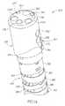
図1aは、本発明の例示的な実施形態による複数の視野を有する内視鏡(例えば、結腸鏡)200の外観等角図を概略的に示す。 FIG. 1a schematically illustrates an external isometric view of an endoscope (eg, colonoscope) 200 having multiple fields of view according to an exemplary embodiment of the present invention.
本発明の例示的な実施形態によれば、内視鏡200のヘッド230は、少なくとも直視カメラ(TVカメラなど)と、少なくとも側視カメラ(TVカメラなど)とを備える。 According to an exemplary embodiment of the present invention, the
図1aは、ヘッド230の前面320上にある直視カメラ116(図2cに示す)の前方カメラ要素236を示す。用語「カメラ要素」とは、一般にカメラおよびカメラに関する光学系/アセンブリを指す。直視カメラ116(例えば図2aに示す)の光軸は、実質的に内視鏡の長手に沿った方向に向けられている。しかしながら、直視カメラ116は一般的には広角カメラであるため、その視野(FOV)は、その光軸に対して大きな角度で視野の方向を含んでもよい。さらに、発光ダイオード(LED)などの離散光源240aおよび240bの光学窓242aおよび242bも、ヘッド230の前面320上にみられる。FOVの照明に使用されるLEDの数は、変更されてもよいことに注意されたい。ワーキングチャネル262の遠位開口部340(例えば図2dに示す)は、好ましくは、ヘッド230の前面320上に配置されて、ワーキングチャネル262を介して挿入され、前面320を越えて配備された手術道具を直視カメラ116から観察できるようにしてもよい。 FIG. 1 a shows the
流体チャネルの遠位開口部344も、好ましくは、ヘッド230の前面320上に配置されてもよい。遠位開口部344に繋がる流体チャネルは、結腸を洗浄するための噴射チャネルとして使用されてもよい。 The fluid channel
ノズル部348を有する液体注入部346は、前方カメラ要素236に向けられ、流体を注入して、直視カメラの前方カメラ要素236から血液、排泄物およびその他の細片などの汚染物質を洗浄するために使用される。任意で、同じ注入部は、前方カメラ要素236ならびに1つまたは両方の光学窓242aおよび242bの両方の洗浄のために使用される。注入部346は、流体チャネルから流体(例えば、水および気体の両方、またはいずれか一方)を供給されてもよく、または、専用の洗浄流体チャネルから流体を供給されてもよい。 A
ヘッド230の側壁362上には、側視カメラ220(2つのこうしたカメラを図2aに示す)の前方カメラ要素256と、LED250などの離散光源の光学窓252とがみられる。離散光源の数は、変更されてもよいことに注意されたい。側視カメラ220の光軸は、実質的に内視鏡の長手に対して直交する方向に向けられている。しかしながら、側視カメラ220は一般的には広角カメラであるため、その視野は、その光軸に対して大きな角度で視野の方向を含んでもよい。 On the
ノズル部368を有する液体注入部366は、前方カメラ要素256に向けられ、流体を注入して、側視カメラの前方カメラ要素256から血液、排泄物およびその他の細片などの汚染物質を洗浄するために使用される。任意で、同じ注入部は、前方カメラ要素256および光学窓252の両方の洗浄のために使用される。好ましくは、注入部346および366は、同じチャネルから流体を供給される。任意の溝370は、ノズル部368からの洗浄流体を前方カメラ要素256に向けて方向付けるのを助ける。溝370は、側壁362が直腸壁に接近または押し付けられる際に有益なことがある。任意で、注入部366は、溝370内において少なくとも部分的に窪ませてもよく、このことにより、ヘッド230の最大部直径を低減し、注入部366との摩擦により直腸壁を傷つける危険を低減してもよい。 A
図示の実施形態では、可撓性シャフト260は、ピボット384により互いに接続される複数のリンク382から構成される。リンク382により、ピボット384が限られた可撓性を提供して、内視鏡を押したり、引いたり、回転させたりできる。シャフトは、好ましくは、弾性シースで覆われる(明確にするために図示せず)。リンク382の管腔は、ワーキングチャネル262を保持する。開口部344に接続される流体チャネル、任意の洗浄流体チャネル、ならびに、LEDおよびカメラに電力を供給し、カメラからビデオ信号を伝達する電気ケーブルは、図示されていない。一般に、シャフトは、例えば使用中、ヘッドを方向付けたり向けたりするためのリンクに取り付けられたケーブルなど、機械的アクチュエータ(図示せず)をさらに備えてもよい。 In the illustrated embodiment, the
図1aには1つの側視カメラのみ示したが、任意で、一部の実施形態によれば、2つまたは3つ以上の側視カメラをヘッド230内に配置してもよいことに注意されたい。2つの側視カメラを使用する際、側視カメラは、好ましくは、それらの視野が実質的に反対を向くように設置される。一部の実施形態によれば、異なる構成および数の側視カメラが可能であり、本発明の一般的な範囲内に包含される。 Although only one side view camera is shown in FIG. 1a, it is noted that optionally, according to some embodiments, two or more side view cameras may be located in the
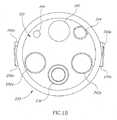
図1bは、本発明の例示的な実施形態による複数の視野を有する内視鏡200のヘッド230の正面図を概略的に示す。 FIG. 1b schematically illustrates a front view of a
本発明の例示的な実施形態によれば、内視鏡200のヘッド230は、少なくとも直視カメラと、少なくとも側視カメラとを備える。図2bは、ヘッド230の前面320上にある直視カメラ116の前方カメラ要素236を示す。さらに、LEDの光学窓242aおよび242bも、ヘッド230の前面320上にみられる。ワーキングチャネルの遠位開口部340および流体チャネルの遠位開口部344も、好ましくは、ヘッド230の前面320上に配置されてもよい。ノズル部348を有する液体注入部346もここに示す。 According to an exemplary embodiment of the present invention, the
さらに、液体注入部366aおよび366bは、それぞれ側視カメラ要素256aおよび256bに向けられ、流体を注入して、側視カメラの前方カメラ要素256から血液、排泄物およびその他の細片などの汚染物質を洗浄するために使用される。 In addition, the
図1cは、本発明の例示的な実施形態による複数の視野を有する内視鏡200の側面図を概略的に示す。 FIG. 1c schematically illustrates a side view of an
図1cは、ヘッド230の側壁362上にある側視カメラ220の前方カメラ要素256、溝370、および光学窓252を示す。液体注入部346および366もここに示す。 FIG. 1 c shows the
図2aは、本発明の別の例示的な実施形態による複数の視野を有する内視鏡400の切欠等角図を概略的に示す。 FIG. 2a schematically illustrates a cut-away isometric view of an endoscope 400 having multiple fields of view according to another exemplary embodiment of the present invention.
本発明の例示的な実施形態によれば、内視鏡200のヘッド230は、少なくとも直視カメラ116ならびに2つの側視カメラ220aおよび220bを備える。 According to an exemplary embodiment of the present invention, the
直視方向の照明に使用されるLEDの光学窓242aおよび242bも、ヘッド230の前面上にみられる。 LED
ワーキングチャネルの遠位開口部340は、好ましくは、ヘッド230の前面上に配置されて、ワーキングチャネル262を介して挿入され、前面を越えて配備された手術道具を直視カメラ116から観察できるようにしてもよい。 The
流体チャネルの遠位開口部344も、好ましくは、ヘッド230の前面上に配置されてもよい。遠位開口部344に繋がる流体チャネルは、結腸を洗浄するための噴射チャネルとして使用されてもよい。 The fluid channel
ノズル部を有する液体注入部346は、カメラ116の前方カメラ要素に向けられ、流体を注入して、直視カメラ116の前方カメラ要素から血液、排泄物およびその他の細片などの汚染物質を洗浄するために使用される。任意で、同じ注入部は、前方カメラ要素ならびに1つまたは両方の光学窓242aおよび242bの両方の洗浄のために使用される。注入部346は、流体チャネルから流体を供給されてもよく、または、専用の洗浄流体チャネルから流体を供給されてもよい。 A
ヘッド230の右側には、側視カメラ220bの前方カメラ要素256と、側視照明LEDの光学窓252bとがみられる。 On the right side of the
ノズル部を有する液体注入部366bは、前方カメラ要素256bに向けられ、流体を注入して、側視カメラ220bの前方カメラ要素256bから血液、排泄物およびその他の細片などの汚染物質を洗浄するために使用される。任意で、同じ注入部は、前方カメラ要素256bおよび光学窓252bの両方の洗浄のために使用される。任意の溝370bは、注入部366bからの洗浄噴射を前方カメラ要素256bに向けて方向付けるのを助ける。 A liquid injection portion 366b having a nozzle portion is directed to the front camera element 256b and injects fluid to clean contaminants such as blood, excrement and other debris from the front camera element 256b of the side view camera 220b. Used for. Optionally, the same infusion is used for cleaning both the front camera element 256b and the
ここに図示されていないが、等価の要素366a、370a、256aおよび252aは、ヘッド230の左側に存在することが理解される。 Although not shown here, it is understood that
好ましくは、全ての注入部346および366は、同じチャネルから流体を供給される。 Preferably, all
図示の実施形態では、可撓性シャフト260は、複数のリンク382から構成される(明確にするために、1つだけ指す)。シャフト260内の電気ケーブル396がみられ、カメラ116、220aおよび220bに接続されている。同じまたは別個の電気ケーブルが使用されて、LEDに電力を供給する。 In the illustrated embodiment, the
図2bは、本発明の例示的な実施形態による複数の視野を有する内視鏡220の断面図を、ヘッド230の一部詳細を示して、概略的に示す。 FIG. 2 b schematically illustrates a cross-sectional view of an
本発明によれば、内視鏡200のヘッド230は、少なくとも直視カメラ116ならびに2つの側視カメラ220aおよび220bを備える。それぞれのカメラ116および220は、それぞれレンズアセンブリ(系)132および232、ならびに、それぞれ固体検出器アレイ134および234などの光学結像系とともに提供される。カメラ116および220のそれぞれの前方カメラ要素236および256は、平坦な保護窓であってもよいが、任意で、それぞれ固体検出器アレイ134および234などの結像系の一部として使用される光学要素であってもよい。任意で、カメラ116および220は、類似または同一であるが、異なるカメラ設計を使用してもよく、例えば、視野118と218とが異なることもある。追加的にまたは代替的に、分解能、光感度、画素寸法および画素数、焦点距離、作動距離および被写界深度などのその他のカメラパラメータは、同じまたは異なるように選択されてもよい。 According to the present invention, the
視野を照らす光は、発光ダイオード(LED)により提供される。一部の実施形態によれば、白色LEDを使用してもよい。一部の実施形態によれば、その他の色のLEDまたは任意の組み合わせのLEDを使用してもよい(例えば、赤、緑、青、赤外、紫外など)。 Light that illuminates the field of view is provided by light emitting diodes (LEDs). According to some embodiments, white LEDs may be used. According to some embodiments, other color LEDs or any combination of LEDs may be used (eg, red, green, blue, infrared, ultraviolet, etc.).
図示の実施形態では、直視カメラ116の視野118は、内視鏡ヘッド230内に配置され、光学窓242aおよび242bによりそれぞれ保護される2つのLED240aおよび240bによって照らされる。 In the illustrated embodiment, the field of
同様に、図示の実施形態では、側視カメラ220の視野は、内視鏡ヘッド230内に配置され、光学窓252により保護される単独のLED250によって照らされる。LED光源の数およびカメラに対するそれらの位置は、本発明の範囲内で変更されてもよいことに注意されたい。例えば、同じ保護窓の後ろにLEDがほとんどなくてもよいし、同じ保護窓の後ろにカメラおよびLEDまたは複数のLEDが配置されてもよい、などである。 Similarly, in the illustrated embodiment, the field of view of the
内視鏡200のヘッド230は、可撓性シャフト260の遠位端部に配置される。当該技術分野のシャフトと同様に、シャフト260は、手術道具を挿入するためのワーキングチャネル262を備える。さらに、シャフト260は、洗浄、送気、吸引、および結腸壁を洗浄するための液体の供給のためのチャネルを備えてもよい。 The
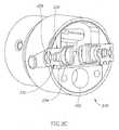
図2cは、本発明の例示的な実施形態による内視鏡200の切欠断面図を、ヘッド230の一部詳細を示して、概略的に示す。簡単にするために、図では、2つの側視カメラのうちの1つの詳細を示す。 FIG. 2 c schematically illustrates a cutaway cross-sectional view of the
本発明によれば、内視鏡200のヘッド230は、少なくとも1つの側視カメラ220を備える。それぞれのカメラ220は、レンズアセンブリ232および固体検出器アレイ234などの光学結像系とともに提供される。カメラ220の前方カメラ要素256は、平坦な保護窓または結像系232の一部として使用される光学要素であってもよい。 According to the present invention, the
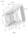
図2dは、本発明の例示的な実施形態による複数の視野を有する内視鏡220の断面図を、ヘッド230の一部詳細を示して、概略的に示す。 FIG. 2d schematically illustrates a cross-sectional view of an
本発明の一部の実施形態によれば、ヘッド230の内部は、直視カメラ116および側視カメラ220を備える。カメラ116および220の両方、またはいずれか一方はそれぞれ、複数のレンズ430から434および保護ガラス436(図示せず)を有するレンズアセンブリ132および232(図示せず)と、プリント基板135および235(図示せず)に接続される固体検出器アレイ134および234(図示せず)とを備える。カメラ116および220またはそれらに関係する任意の要素(例えば、レンズアセンブリ132および232、レンズ430から434および保護ガラス436、固体検出器アレイ134および234、または、プリント基板135および235、またはこれらの組み合わせなど)は、同じであってもよいし異なってもよいことに注意されたい。換言すると、直視カメラおよび側視カメラは、それらの構成要素またはそれらに関係するその他の要素(例えば光学要素など)の任意の1つまたは任意の組み合わせにおいて、同じであってもよいし異なってもよい。 According to some embodiments of the invention, the interior of the
図3は、本発明の例示的な実施形態によるカメラ116または220の断面図を、レンズアセンブリ132および232の一部詳細を示して、概略的に示す。本発明の一部の実施形態によれば、カメラ116または220は、同じであってもよいし異なってもよいことに注意されたい。任意で、カメラ116の焦点距離は、カメラ220のものと比べてわずかに異なる。焦点距離における違いは、例えば、レンズアセンブリ132および232の両方、またはいずれか一方を備えるレンズの間、または、レンズアセンブリと検出器アレイとの間の距離を(わずかに)変えることにより達成される。 FIG. 3 schematically illustrates a cross-sectional view of a
レンズ431および432の間の空隙「S」は、絞りとして作用する。空隙Sは、集束範囲(レンズ系の最適な焦点合わせの範囲外となることによる過度のぼけがなく、結像可能な最も近い物体とより遠い物体との間の距離)に影響を及ぼしてもよい。 The gap “S” between the
本発明の例示的な実施形態によれば、カメラ116および220は、それぞれレンズアセンブリ132および232を備える。レンズアセンブリは、一組のレンズ430から434および保護ガラス436を備える。 According to an exemplary embodiment of the invention,
レンズ430から434は、(任意で金属製の)バレル410およびそこへの(例えば、バレル410に接着される)コネクタ内に置かれる。レンズアセンブリ132および232の両方、またはいずれか一方のうちの任意の1つは、図3のように任意で、バレル410内に配置されるアダプタ411を含んでもよい。アダプタ411は、1つまたは2つ以上のレンズの位置を調整し、レンズ間の距離を調整するように構成される。アダプタ411はまた、(この場合、レンズ432および433の間の)絞りとして機能するように構成されてもよい。保護ガラス436は、固体検出器アレイ134または234に近接して置かれ、任意でそこへ取り付けられる。 Lenses 430-434 are placed in a barrel 410 (optionally made of metal) and a connector thereto (eg, glued to barrel 410). Any one of
作動距離(レンズ系により最適に焦点合わせされる物体までの距離)は、レンズ434と保護ガラス436との間の距離を変えることにより変えられてもよい。レンズ434がバレルに固定され、また、保護ガラス436はレンズホルダ136(236)に固定されることから、この距離は、レンズホルダ136(236)のバレル410に対する相対的な位置を変えることにより変えられてもよい。レンズ434と保護ガラス436との間の空間は、何もない空間であってもよいし、ガラスもしくはその他の透明な材料で満たされてもよく、または、これらのレンズの間に管状のスペーサ部材を挿入して、正確な距離を保証してもよい。任意で、光学フィルタを空間内に配置してもよい。カメラ116および220は、それぞれ固体検出器アレイ134および234をさらに備える。固体検出器アレイ134および234は、それぞれプリント基板に接続されるものであってもよい。電気ケーブル配線は、プリント基板を内視鏡の中央制御システムユニットに接続してもよい。 The working distance (the distance to the object that is optimally focused by the lens system) may be changed by changing the distance between the
固体検出器アレイ134および234は、それぞれレンズホルダ136および236に取り付けられる。レンズホルダ136または236は、検出器アレイカバーをバレル410に取り付けることにより、それぞれレンズアセンブリ132または232に取り付けられる。 Solid
一部の用途では、保護ガラス436は、両面が平坦な光学要素であってもよく、主に検出器アレイ(例えば検出器アレイ134および234など)の保護として作用し、任意で、アレイとともに供給されてもよい。しかしながら、光学設計において保護ガラス436の光学特性を考慮に入れる必要がある。 For some applications, the
レンズアセンブリ132または232を組み立てるために、レンズ430が最初に左から、次いで431、そして432が右から挿入されてもよい。レンズ433および434は、併せて接着(または例えば空気により離間)されてもよいが、次いで右から挿入される。ここにおいて、完全な一組がバレル内に置いて組み立てられる。組み立てられた検出器(例えば、検出器アレイ134および234)、保護ガラス436およびカバー136(236)は、次いで加えられる。 To assemble the
図4a、4bおよび4cは、本発明によるレンズアセンブリ132および232などのレンズアセンブリのための3つの例を示し、それぞれ対物レンズ系510、520および530を有する。レンズアセンブリ132および232において使用されるセンサは、この例示的な実施形態によれば、マイクロレンズのアレイを有する電荷結合素子センサ(CCD)であってもよいが、CMOSなどその他のセンサもまた使用されてもよい。 FIGS. 4a, 4b and 4c show three examples for lens assemblies such as
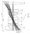
本発明の例示的な実施形態において、約800×600画素の分解能を有するカラーCCDカメラが、全アクティブ領域が約3.3×2.95mmの状態で使用された。レンズの光学的分解能は、本発明の例示的な実施形態によれば、センサの分解能と一致するように設計される。対物レンズ系510(520/530)は、好ましくは、色収差、球面収差および非点収差に関して補正される。本発明の例示的な実施形態において、対物レンズ系510(520/530)は、前面レンズの前面からセンサの前面まで測定した全長が約4.60mm(4.62)である。本発明の例示的な実施形態において、対物レンズ系510および520は、約170°の受光角を有する広角の対物レンズである。本発明の例示的な実施形態において、対物レンズ系510(520/530)は、前面レンズの前面から撮像される物体まで測定した作動距離が短い。本発明の例示的な実施形態において、対物レンズ系510(520/530)は、4−110mmの間(または、3.5−50mmの間)で物体を効果的に撮像可能とする焦点深度(DOF)を有する。本発明の例示的な実施形態において、対物レンズ系510、520および530は、前面レンズの直径により規定される約2.5mmの最大部直径を有し、約3.6mmの最大部外径を有するバレル内に格納される。その他の設計パラメータは、本発明の範囲内で選択されてもよいことに注意されたい。 In an exemplary embodiment of the invention, a color CCD camera with a resolution of about 800 × 600 pixels was used with a total active area of about 3.3 × 2.95 mm. The optical resolution of the lens is designed to match the resolution of the sensor, according to an exemplary embodiment of the invention. The objective lens system 510 (520/530) is preferably corrected for chromatic aberration, spherical aberration and astigmatism. In an exemplary embodiment of the invention, the objective lens system 510 (520/530) has a total length measured from the front surface of the front lens to the front surface of the sensor of about 4.60 mm (4.62). In an exemplary embodiment of the invention,
対物レンズ系510(520/530)は、点線で示す光軸「O」を有する。レンズ系は、前群サブシステム510a(520a/530a)と、後方サブシステム510b(520b/530b)とを備える。 The objective lens system 510 (520/530) has an optical axis “O” indicated by a dotted line. The lens system includes a front group subsystem 510a (520a / 530a) and a rear subsystem 510b (520b / 530b).
前群サブシステム510a(520a)(図4a(4b))は、観察対象の物体の最も近くに配置され、負の屈折力を有する前面レンズ430(430’)と、正の屈折力を有するレンズ431(431’)とを備える。 The front group subsystem 510a (520a) (FIG. 4a (4b)) is arranged closest to the object to be observed and has a front lens 430 (430 ′) having a negative refractive power and a lens having a positive refractive power. 431 (431 ′).
前面レンズ430(430’)は、その陥凹面が観察対象の物体に面するような方向に向けられ、任意で、光軸に直交する方向において、後群サブシステム510bの最大部寸法よりも実質的に大きい直径を有する。レンズ431(431’)は、正の屈折力を有する。 The front lens 430 (430 ′) is oriented in a direction such that its concave surface faces the object to be observed, and optionally substantially larger than the maximum dimension of the rear group subsystem 510b in the direction perpendicular to the optical axis. Has a large diameter. The lens 431 (431 ') has a positive refractive power.
後群サブシステム510b(520b)は、レンズ432、433、434および保護ガラス436(レンズ432’、433’、434’および436’)を備え、432(432’)が負の屈折力を有し、433(433’)が正の屈折力を有し、434(434’)が負の屈折力を有し、436(436’)が基本的に屈折力を持たない。保護ガラス436(436’)は、センサの一部分または後群サブシステム510b(520b)の一部分であってもよいことに注意されたい。後群サブシステム510b(520b)のレンズ433および434(433’および434’)は、色消しサブアセンブリ(図4aのような、レンズ433および434が固定された複合色消しサブアセンブリ、または、図4bのような、レンズ433’およびレンズ434’が分離される非複合色消しサブアセンブリ)を構成する。レンズ433(433’)は、後述の表T1、T2において示されるように、その前面の曲率半径がその後面の曲率半径より小さい状態で、両凸であってもよい。The rear group subsystem 510b (520b) includes
対物レンズ系510のレンズ432は、次の条件を満たす焦点距離f432を有していてもよい。f432≦1.8f、ただし、fは全系の合成焦点距離である。具体的には、表T1に示されたデータ、f432=2.05およびf=1.234mmについては、条件f432≦1.8は満たされる。The
対物レンズ系520のレンズ432’は、次の条件を満たす焦点距離f432’を有していてもよい。f432≦1.8f。The
具体的には、表T2に示されたデータ、f432=2.05およびf=1.15mmについては、条件f432≦1.8は満たされる。Specifically, the data presented in TableT2, for
レンズは、反射防止コーティング(ARコーティング)でコーティングされて、レンズアセンブリ132(232)の効率をさらに改善してもよい。 The lens may be coated with an anti-reflective coating (AR coating) to further improve the efficiency of the lens assembly 132 (232).
有効開口絞りS1(S2)は、レンズ431および432(431’および432’)の間に形成される。有効開口絞りS1(S2)は、前群サブシステム510a(520a)と後群サブシステム510b(520b)との間を隔ててもよい。The effective aperture stop S1 (S2 ) is formed between the
前群サブシステム530a(図4c)は、観察対象の物体の最も近くに配置され、負の屈折力を有する前面レンズ430”と、正の屈折力を有するレンズ431”とを備える。前群サブシステム530a(図4c)は、第1の前方負レンズ430”と第2の前方正レンズ431”との間に配置される追加の前方正レンズ(メニスカスレンズ429など)をさらに備える The front group subsystem 530a (FIG. 4c) includes a
前面レンズ430”は、その陥凹面が観察対象の物体に面するような方向に向けられ、任意で、光軸に直交する方向において、後群サブシステム530bの最大部寸法よりも実質的に大きい直径を有する。
後群サブシステム530bは、レンズ432”、433”、434”および保護ガラス436”を備え、432”が負の屈折力を有し、433”が正の屈折力を有し、434”が負の屈折力を有し、436”が基本的に屈折力を持たない。保護ガラス436”は、センサの一部分または後群サブシステム530bの一部分であってもよいことに注意されたい。レンズ433”および434”は、後群サブシステム530bの色消しサブアセンブリを構成する、または、互いに固定されてはならない。レンズ433”は、後述の表T3において示されるように、その前面の曲率半径がその後面の曲率半径より小さい状態で、両凸であってもよい。The rear group subsystem 530b includes
対物レンズ系530のレンズ432”は、次の条件を満たす焦点距離f432を有していてもよい。f432”≦1.8f、ただし、fは全系の合成焦点距離である。具体的には、表T3に示されたデータ、f432”=2.26およびf=1.06mmについては、条件f432”≦1.8は満たされる。The
レンズは、反射防止コーティング(ARコーティング)でコーティングされて、レンズアセンブリ132(232)の効率をさらに改善してもよい。 The lens may be coated with an anti-reflective coating (AR coating) to further improve the efficiency of the lens assembly 132 (232).
有効開口絞りS3は、レンズ431”および432”の間に形成される。有効開口絞りS3は、前群サブシステム530aと後群サブシステム530bとの間を隔ててもよい。Effective aperture stopS 3 is formed between the
表T1、T2およびT3は、本発明の一部の実施形態による対物レンズ系510、520および530それぞれにおけるレンズのパラメータをまとめる。
表T1(FOV=164°、DOF=3−110mm、f=1.234mm、全光路長 4.09mm)
Table T1 (FOV = 164 °, DOF = 3-110 mm, f = 1.234 mm, total optical path length 4.09 mm)
表3は、追加の正レンズ429(例えば、表3に示されるようなメニスカスレンズ)をさらに備える6つの構成要素の系の例を示す。
表T3(FOV=164°、DOF=3−110mm、f=1.06mm、全光路長 4.69mm)
R2−レンズの後面の曲率半径(物体と反対を向く)
Th−レンズの厚さ−前面の中心から後面の中心まで
ガラス−レンズのガラスの種類
d1−レンズの前方光学面の半径
d2−レンズの後方光学面の半径
D−レンズなどの構成要素の後面の中心から次隣の光学要素の前面まで測定されたレンズなどの構成要素の間の距離(絞りSの場合、距離は、絞りの前方にある構成要素の後面の中心から次隣の構成要素の前面まで測定される)
一般的に用いられるように、曲率半径が無限大とは、平面であると解釈される。全てのレンズは任意で球面である。Table 3 shows an example of a six component system further comprising an additional positive lens 429 (eg, a meniscus lens as shown in Table 3).
Table T3 (FOV = 164 °, DOF = 3-110 mm, f = 1.06 mm, total optical path length 4.69 mm)
R2- radius of curvature of the rear surface of the lens (facing away from the object)
Th-Lens thickness-Glass from front center to rear center-Lens glass type d1- Radius of front optical surface of lens d2- Radius of rear optical surface of lens D-Components such as lens The distance between components, such as a lens, measured from the center of the rear surface to the front surface of the next adjacent optical element (in the case of aperture S, the distance is the next component from the center of the rear surface of the component in front of the aperture Is measured to the front)
As commonly used, an infinite radius of curvature is interpreted as a plane. All lenses are optionally spherical.
図4a、4bおよび4cは、さらに、対物レンズ系510、520および530をそれぞれ介する、5つの入射光線R1からR6の伝播を、前面レンズ430(図4a)、430’(図4b)または430”(図4c)から結像面における物体の像生成まで示す。4a, 4b and 4c further illustrate the propagation of five incident rays R1 to R6 through
光線R1からR6は、それぞれα1(アルファ1)からα6(アルファ6)の角度でレンズアセンブリに入射し、例えば、基本的に次の角度、α1=0°、α2=45°、α3=60°、α4=75°およびα5=84°に等しい。対応する入射角(センサのマイクロレンズを通過してきた光線と、系の光軸との間の角)は、β1(ベータ1)からβ6(ベータ6)である。一部の実施形態によれば、主入射角(例えば図4a−図4cにおける光線R6を形成する入射角)は、20°よりも大きい、25°よりも大きい、30°よりも大きい、または約20−40°の間である。レンズ系は、本発明の一部の実施形態によれば、歪みを最低限にする(例えば、80%未満)。Rays R1 to R6 enter the lens assembly at angles α1 (alpha 1) to α6 (alpha 6), respectively, for example, basically the following angles: α1 = 0 °, α2 = 45. Equivalent to °, α3 = 60 °, α4 = 75 ° and α5 = 84 °. The corresponding incident angle (the angle between the light beam that has passed through the sensor microlens and the optical axis of the system) is β1 (beta 1) to β6 (beta 6). According to some embodiments, the main angle of incidence (eg, the angle of incidence forming ray R6 in FIGS. 4a-4c) is greater than 20 °, greater than 25 °, greater than 30 °, or Between about 20-40 °. The lens system minimizes distortion (eg, less than 80%) according to some embodiments of the invention.
光学系アセンブリ132(232)は、以下のステップを備える方法により組み立てられてもよい。
任意で、後方の複レンズ433−434(433’−434’)を固定するステップ、
および、
前面レンズ430(430’)をバレル内で組み立てるステップ、
レンズ431(431’)をバレル内で組み立てるステップ、
レンズ432(432’)をバレル内で組み立てるステップ、
後方の複レンズ433−434(433’−434’)をバレル内で組み立てるステップ。
また、前面レンズ430(430’)は最後に組み立てられてもよいことに注意されたい。The optical system assembly 132 (232) may be assembled by a method comprising the following steps.
Optionally, fixing the rear double lens 433-434 (433'-434 ');
and,
Assembling front lens 430 (430 ′) in the barrel;
Assembling the lens 431 (431 ′) in the barrel;
Assembling lens 432 (432 ') in the barrel;
Assembling the rear double lenses 433-434 (433′-434 ′) in the barrel.
Note also that the front lens 430 (430 ′) may be assembled last.
本発明をその特定の実施形態と併せて説明してきたが、多くの代替、変更および変形が当業者には自明であることは明らかである。したがって、添付の請求項の思想および広い範囲内にあるそのような代替、変更および変形を全て含むことを意図している。本明細書において言及された全ての刊行物、特許および特許出願は、個々の刊行物、特許および特許出願が具体的かつ個別に参照として組み込まれるよう定められている場合と同じ程度まで、その全体が本明細書に参照として組み込まれる。さらに、本明細書におけるいかなる参考文献の引用または同定も、そのような参考文献が本発明の先行技術として入手可能であるとの承認であると解釈されるべきではない。 While the invention has been described in conjunction with specific embodiments thereof, it is evident that many alternatives, modifications and variations will be apparent to those skilled in the art. Accordingly, it is intended to embrace all such alternatives, modifications and variations that fall within the spirit and broad scope of the appended claims. All publications, patents and patent applications mentioned in this specification are to their full extent to the extent that individual publications, patents and patent applications are specifically and individually incorporated by reference. Is incorporated herein by reference. In addition, citation or identification of any reference herein shall not be construed as an admission that such reference is available as prior art to the present invention.
Claims (21)
Translated fromJapanese直視方向向きのカメラセンサと、
直視対物レンズ系と、
側視方向向きのカメラセンサと、
側視対物レンズ系とを備え、
前記直視および側視対物レンズ系のうちの少なくとも1つが絞り羽根により分離される前群および後群サブシステムを備え、
前記前群サブシステムが、物体側から順に、第1の前方負レンズと第2の前方正レンズとを備え、
前記後群サブシステムが、物体側から順に、第1の後方正レンズと、第2の後方正レンズを備える色消しサブアセンブリ(任意で、複合色消しサブアセンブリ)と、第3の後方負レンズとを備え、以下の条件、
f(第1の後方正レンズ)≦1.8fを満たすが、ただし、fは全レンズ系の合成焦点距離、および、f(第1の後方正レンズ)は、前記第1の後方正レンズの焦点距離である光学系。An optical system for a tip portion of a multi-sensor endoscope,
A camera sensor facing the direct view direction,
A direct-view objective lens system;
A camera sensor facing the side view direction;
A side-view objective lens system,
A front group and a rear group subsystem in which at least one of the direct-view and side-view objective lens systems is separated by a diaphragm blade;
The front group subsystem includes, in order from the object side, a first front negative lens and a second front positive lens;
The rear group subsystem includes, in order from the object side, an achromatic subassembly (optionally a composite achromatic subassembly) including a first rear positive lens, a second rear positive lens, and a third rear negative lens. With the following conditions:
f (first rear positive lens) ≦ 1.8f, where f is the total focal length of the entire lens system, and f (first rear positive lens) is that of the first rear positive lens. An optical system that is the focal length.
絞り羽根により分離される前群および後群サブシステムを備え、
前記前群サブシステムが、第1の前方負レンズと第2の前方正レンズとを備え、
前記後群サブシステムが、第1の後方正レンズと、第2の後方正レンズを備える色消しサブアセンブリ(任意で、複合色消しサブアセンブリ)と、第3の後方負レンズとを備え、
以下の条件、
f(第1の後方正レンズ)≦1.8fを満たすが、ただし、fは全レンズ系の合成焦点距離、および、f(第1の後方正レンズ)は、前記第1の後方正レンズの焦点距離である、対物レンズ系。An objective lens system for at least one of a direct-view direction camera sensor and a side-view direction camera sensor of a multi-sensor endoscope,
A front group and a rear group subsystem separated by a diaphragm blade;
The front group subsystem comprises a first front negative lens and a second front positive lens;
The rear group subsystem comprises a first rear positive lens, an achromatic subassembly comprising a second rear positive lens (optionally a composite achromatic subassembly), and a third rear negative lens;
The following conditions,
f (first rear positive lens) ≦ 1.8f, where f is the total focal length of the entire lens system, and f (first rear positive lens) is that of the first rear positive lens. Objective lens system that is the focal length.
直視方向向きのカメラセンサと、
直視対物レンズ系と、
側視方向向きのカメラセンサと、
側視対物レンズ系とを備え、
前記直視および側視対物レンズ系のうちの少なくとも1つが絞り羽根により分離される前群および後群サブシステムを備え、
前記前群サブシステムが、第1の前方負レンズと第2の前方正レンズとを備え、
前記後群サブシステムが、第1の後方正レンズと、第2の後方正レンズを備える色消しサブアセンブリ(任意で、複合色消しサブアセンブリ)と、第3の後方負レンズとを備え、以下の条件、
f(第1の後方正レンズ)≦1.8fを満たすが、ただし、fは全レンズ系の合成焦点距離、および、f(第1の後方正レンズ)は、前記第1の後方正レンズの焦点距離である、マルチセンサ内視鏡の先端部分。A tip portion of a multi-sensor endoscope including an optical system,
A camera sensor facing the direct view direction,
A direct-view objective lens system;
A camera sensor facing the side view direction;
A side-view objective lens system,
A front group and a rear group subsystem in which at least one of the direct-view and side-view objective lens systems is separated by a diaphragm blade;
The front group subsystem comprises a first front negative lens and a second front positive lens;
The rear group subsystem comprises an achromatic subassembly (optionally a composite achromatic subassembly) comprising a first rear positive lens, a second rear positive lens, and a third rear negative lens, Conditions,
f (first rear positive lens) ≦ 1.8f, where f is the total focal length of the entire lens system, and f (first rear positive lens) is that of the first rear positive lens. The tip of the multi-sensor endoscope, which is the focal length.
Applications Claiming Priority (3)
| Application Number | Priority Date | Filing Date | Title |
|---|---|---|---|
| US40749510P | 2010-10-28 | 2010-10-28 | |
| US61/407,495 | 2010-10-28 | ||
| PCT/IL2011/000832WO2012056453A2 (en) | 2010-10-28 | 2011-10-27 | Optical systems for multi-sensor endoscopes |
Related Child Applications (1)
| Application Number | Title | Priority Date | Filing Date |
|---|---|---|---|
| JP2016105009ADivisionJP6262285B2 (en) | 2010-10-28 | 2016-05-26 | Optical system for multi-sensor endoscope |
Publications (2)
| Publication Number | Publication Date |
|---|---|
| JP2013542467Atrue JP2013542467A (en) | 2013-11-21 |
| JP5944912B2 JP5944912B2 (en) | 2016-07-05 |
Family
ID=45994487
Family Applications (2)
| Application Number | Title | Priority Date | Filing Date |
|---|---|---|---|
| JP2013535586AActiveJP5944912B2 (en) | 2010-10-28 | 2011-10-27 | Optical system for multi-sensor endoscope |
| JP2016105009AActiveJP6262285B2 (en) | 2010-10-28 | 2016-05-26 | Optical system for multi-sensor endoscope |
Family Applications After (1)
| Application Number | Title | Priority Date | Filing Date |
|---|---|---|---|
| JP2016105009AActiveJP6262285B2 (en) | 2010-10-28 | 2016-05-26 | Optical system for multi-sensor endoscope |
Country Status (5)
| Country | Link |
|---|---|
| US (3) | US20130296649A1 (en) |
| EP (2) | EP3540495A1 (en) |
| JP (2) | JP5944912B2 (en) |
| CN (1) | CN103403605A (en) |
| WO (1) | WO2012056453A2 (en) |
Cited By (39)
| Publication number | Priority date | Publication date | Assignee | Title |
|---|---|---|---|---|
| WO2015151973A1 (en)* | 2014-03-31 | 2015-10-08 | オリンパス株式会社 | Endoscope system |
| JP2016523661A (en)* | 2013-07-01 | 2016-08-12 | エンドチョイス インコーポレイテッドEndochoice, Inc. | Circuit board assembly for multi-view element endoscope |
| US9474440B2 (en) | 2009-06-18 | 2016-10-25 | Endochoice, Inc. | Endoscope tip position visual indicator and heat management system |
| US9667935B2 (en) | 2013-05-07 | 2017-05-30 | Endochoice, Inc. | White balance enclosure for use with a multi-viewing elements endoscope |
| US9706908B2 (en) | 2010-10-28 | 2017-07-18 | Endochoice, Inc. | Image capture and video processing systems and methods for multiple viewing element endoscopes |
| JP2018042625A (en)* | 2016-09-12 | 2018-03-22 | 株式会社デルコ | Trocar with imaging function |
| US9943218B2 (en) | 2013-10-01 | 2018-04-17 | Endochoice, Inc. | Endoscope having a supply cable attached thereto |
| US9949623B2 (en) | 2013-05-17 | 2018-04-24 | Endochoice, Inc. | Endoscope control unit with braking system |
| US9968242B2 (en) | 2013-12-18 | 2018-05-15 | Endochoice, Inc. | Suction control unit for an endoscope having two working channels |
| US10021312B2 (en) | 2014-09-09 | 2018-07-10 | Olympus Corporation | Endoscope system and method for operating endoscope system |
| US10064541B2 (en) | 2013-08-12 | 2018-09-04 | Endochoice, Inc. | Endoscope connector cover detection and warning system |
| US10078207B2 (en) | 2015-03-18 | 2018-09-18 | Endochoice, Inc. | Systems and methods for image magnification using relative movement between an image sensor and a lens assembly |
| US10105039B2 (en) | 2013-06-28 | 2018-10-23 | Endochoice, Inc. | Multi-jet distributor for an endoscope |
| US10123684B2 (en) | 2014-12-18 | 2018-11-13 | Endochoice, Inc. | System and method for processing video images generated by a multiple viewing elements endoscope |
| US10130246B2 (en) | 2009-06-18 | 2018-11-20 | Endochoice, Inc. | Systems and methods for regulating temperature and illumination intensity at the distal tip of an endoscope |
| US10258222B2 (en) | 2014-07-21 | 2019-04-16 | Endochoice, Inc. | Multi-focal, multi-camera endoscope systems |
| US10271713B2 (en) | 2015-01-05 | 2019-04-30 | Endochoice, Inc. | Tubed manifold of a multiple viewing elements endoscope |
| US10292570B2 (en) | 2016-03-14 | 2019-05-21 | Endochoice, Inc. | System and method for guiding and tracking a region of interest using an endoscope |
| US10376181B2 (en) | 2015-02-17 | 2019-08-13 | Endochoice, Inc. | System for detecting the location of an endoscopic device during a medical procedure |
| US10401611B2 (en) | 2015-04-27 | 2019-09-03 | Endochoice, Inc. | Endoscope with integrated measurement of distance to objects of interest |
| US10488648B2 (en) | 2016-02-24 | 2019-11-26 | Endochoice, Inc. | Circuit board assembly for a multiple viewing element endoscope using CMOS sensors |
| US10516865B2 (en) | 2015-05-17 | 2019-12-24 | Endochoice, Inc. | Endoscopic image enhancement using contrast limited adaptive histogram equalization (CLAHE) implemented in a processor |
| US10517464B2 (en) | 2011-02-07 | 2019-12-31 | Endochoice, Inc. | Multi-element cover for a multi-camera endoscope |
| US10524645B2 (en) | 2009-06-18 | 2020-01-07 | Endochoice, Inc. | Method and system for eliminating image motion blur in a multiple viewing elements endoscope |
| US10542877B2 (en) | 2014-08-29 | 2020-01-28 | Endochoice, Inc. | Systems and methods for varying stiffness of an endoscopic insertion tube |
| US10595714B2 (en) | 2013-03-28 | 2020-03-24 | Endochoice, Inc. | Multi-jet controller for an endoscope |
| US10602916B2 (en) | 2014-09-08 | 2020-03-31 | Olympus Corporation | Endoscope system that adjusts luminance of frame image including images of a pluraliry of regions and actuating method for endoscope system |
| US10663714B2 (en) | 2010-10-28 | 2020-05-26 | Endochoice, Inc. | Optical system for an endoscope |
| JP2020140026A (en)* | 2019-02-27 | 2020-09-03 | 株式会社タムロン | Imaging optical system and imaging device |
| US10799103B2 (en) | 2015-05-25 | 2020-10-13 | Olympus Corporation | Endoscope having image acquisition windows and corresponding cleaning nozzles on front and circumferential surfaces |
| JP2020536593A (en)* | 2017-08-17 | 2020-12-17 | 270 サージカル リミテッド | Multi-camera surgical lighting device with variable diameter |
| US10898062B2 (en) | 2015-11-24 | 2021-01-26 | Endochoice, Inc. | Disposable air/water and suction valves for an endoscope |
| JP2021012319A (en)* | 2019-07-09 | 2021-02-04 | 東日本旅客鉄道株式会社 | Push-in type imaging device |
| US10993605B2 (en) | 2016-06-21 | 2021-05-04 | Endochoice, Inc. | Endoscope system with multiple connection interfaces to interface with different video data signal sources |
| US11082598B2 (en) | 2014-01-22 | 2021-08-03 | Endochoice, Inc. | Image capture and video processing systems and methods for multiple viewing element endoscopes |
| US11234581B2 (en) | 2014-05-02 | 2022-02-01 | Endochoice, Inc. | Elevator for directing medical tool |
| US11529197B2 (en) | 2015-10-28 | 2022-12-20 | Endochoice, Inc. | Device and method for tracking the position of an endoscope within a patient's body |
| US12207796B2 (en) | 2013-03-28 | 2025-01-28 | Endochoice Inc. | Multi-jet controller for an endoscope |
| US12342082B2 (en) | 2020-10-02 | 2025-06-24 | Hoya Corporation | Program, information processing method, and endoscope system for generating a composite endoscopic image |
Families Citing this family (73)
| Publication number | Priority date | Publication date | Assignee | Title |
|---|---|---|---|---|
| JPH0625316B2 (en) | 1986-09-29 | 1994-04-06 | 積水化学工業株式会社 | Undercoat composition |
| DE69116170T2 (en) | 1990-12-12 | 1996-08-29 | E.I. Du Pont De Nemours & Co., Wilmington, Del. | NON-ADHESIVE COATING SYSTEM WITH PTFA AND PFA OR FEP FOR CONCENTRATION GRADIENTS |
| US8182422B2 (en) | 2005-12-13 | 2012-05-22 | Avantis Medical Systems, Inc. | Endoscope having detachable imaging device and method of using |
| WO2007087421A2 (en) | 2006-01-23 | 2007-08-02 | Avantis Medical Systems, Inc. | Endoscope |
| US8064666B2 (en) | 2007-04-10 | 2011-11-22 | Avantis Medical Systems, Inc. | Method and device for examining or imaging an interior surface of a cavity |
| US12137873B2 (en) | 2009-06-18 | 2024-11-12 | Endochoice, Inc. | Compact multi-viewing element endoscope system |
| US8926502B2 (en) | 2011-03-07 | 2015-01-06 | Endochoice, Inc. | Multi camera endoscope having a side service channel |
| US10165929B2 (en) | 2009-06-18 | 2019-01-01 | Endochoice, Inc. | Compact multi-viewing element endoscope system |
| US9101268B2 (en) | 2009-06-18 | 2015-08-11 | Endochoice Innovation Center Ltd. | Multi-camera endoscope |
| US9402533B2 (en) | 2011-03-07 | 2016-08-02 | Endochoice Innovation Center Ltd. | Endoscope circuit board assembly |
| US9492063B2 (en) | 2009-06-18 | 2016-11-15 | Endochoice Innovation Center Ltd. | Multi-viewing element endoscope |
| US9706903B2 (en) | 2009-06-18 | 2017-07-18 | Endochoice, Inc. | Multiple viewing elements endoscope system with modular imaging units |
| US9872609B2 (en) | 2009-06-18 | 2018-01-23 | Endochoice Innovation Center Ltd. | Multi-camera endoscope |
| US9901244B2 (en) | 2009-06-18 | 2018-02-27 | Endochoice, Inc. | Circuit board assembly of a multiple viewing elements endoscope |
| US11547275B2 (en) | 2009-06-18 | 2023-01-10 | Endochoice, Inc. | Compact multi-viewing element endoscope system |
| US9101287B2 (en) | 2011-03-07 | 2015-08-11 | Endochoice Innovation Center Ltd. | Multi camera endoscope assembly having multiple working channels |
| US11278190B2 (en) | 2009-06-18 | 2022-03-22 | Endochoice, Inc. | Multi-viewing element endoscope |
| US9713417B2 (en) | 2009-06-18 | 2017-07-25 | Endochoice, Inc. | Image capture assembly for use in a multi-viewing elements endoscope |
| US11864734B2 (en) | 2009-06-18 | 2024-01-09 | Endochoice, Inc. | Multi-camera endoscope |
| WO2010146587A1 (en) | 2009-06-18 | 2010-12-23 | Peer Medical Ltd. | Multi-camera endoscope |
| US9642513B2 (en) | 2009-06-18 | 2017-05-09 | Endochoice Inc. | Compact multi-viewing element endoscope system |
| US12220105B2 (en) | 2010-06-16 | 2025-02-11 | Endochoice, Inc. | Circuit board assembly of a multiple viewing elements endoscope |
| US9560953B2 (en) | 2010-09-20 | 2017-02-07 | Endochoice, Inc. | Operational interface in a multi-viewing element endoscope |
| EP2618718B1 (en) | 2010-09-20 | 2020-04-15 | EndoChoice Innovation Center Ltd. | Multi-camera endoscope having fluid channels |
| US12204087B2 (en) | 2010-10-28 | 2025-01-21 | Endochoice, Inc. | Optical systems for multi-sensor endoscopes |
| CN103403605A (en)* | 2010-10-28 | 2013-11-20 | 恩多巧爱思创新中心有限公司 | Optical systems for multi-sensor endoscopes |
| US11889986B2 (en) | 2010-12-09 | 2024-02-06 | Endochoice, Inc. | Flexible electronic circuit board for a multi-camera endoscope |
| US9320419B2 (en) | 2010-12-09 | 2016-04-26 | Endochoice Innovation Center Ltd. | Fluid channeling component of a multi-camera endoscope |
| CN107361721B (en)* | 2010-12-09 | 2019-06-18 | 恩多巧爱思创新中心有限公司 | Flexible electronic circuit boards for multi-camera endoscopes |
| EP2672878B1 (en) | 2011-02-07 | 2017-11-22 | Endochoice Innovation Center Ltd. | Multi-element cover for a multi-camera endoscope |
| US9456735B2 (en)* | 2012-09-27 | 2016-10-04 | Shahinian Karnig Hrayr | Multi-angle rear-viewing endoscope and method of operation thereof |
| EP2604172B1 (en) | 2011-12-13 | 2015-08-12 | EndoChoice Innovation Center Ltd. | Rotatable connector for an endoscope |
| CA2798716A1 (en) | 2011-12-13 | 2013-06-13 | Peermedical Ltd. | Removable tip endoscope |
| EP2797490B1 (en) | 2011-12-29 | 2016-11-09 | Cook Medical Technologies LLC | Space-optimized visualization catheter having a camera train holder in a catheter with off-centered lumens |
| FR2986337B1 (en)* | 2012-01-31 | 2014-09-05 | Jean-Pierre Lauret | OPTICAL SYSTEM FOR MEASURING BRDF, BSDF AND BDTF |
| US9560954B2 (en) | 2012-07-24 | 2017-02-07 | Endochoice, Inc. | Connector for use with endoscope |
| US20160278615A1 (en)* | 2013-02-05 | 2016-09-29 | Scopernicus, LLC | Wireless endoscopic surgical device |
| US20140221740A1 (en)* | 2013-02-05 | 2014-08-07 | Paul John Kawula | Wireless endoscopic surgical device |
| US11382492B2 (en) | 2013-02-05 | 2022-07-12 | Scopernicus, LLC | Wireless endoscopic surgical device |
| EP3721784B1 (en)* | 2013-03-28 | 2023-12-20 | EndoChoice, Inc. | Compact multi-viewing element endoscope system |
| US9986899B2 (en) | 2013-03-28 | 2018-06-05 | Endochoice, Inc. | Manifold for a multiple viewing elements endoscope |
| US9993142B2 (en) | 2013-03-28 | 2018-06-12 | Endochoice, Inc. | Fluid distribution device for a multiple viewing elements endoscope |
| EP3482673B1 (en)* | 2013-05-06 | 2020-09-16 | EndoChoice, Inc. | Image capture assembly for use in a multi-viewing elements endoscope |
| US10499794B2 (en) | 2013-05-09 | 2019-12-10 | Endochoice, Inc. | Operational interface in a multi-viewing element endoscope |
| DE102014013594A1 (en) | 2013-11-26 | 2015-05-28 | Viimagic Gmbh | Endoscope with several viewing directions |
| WO2016029414A1 (en)* | 2014-08-29 | 2016-03-03 | 深圳市大族激光科技股份有限公司 | Optical lens |
| US10363398B2 (en)* | 2014-10-06 | 2019-07-30 | Sanovas Intellectual Property, Llc | Steerable catheter with flexing tip member |
| JP2016209058A (en)* | 2015-04-30 | 2016-12-15 | ソニー・オリンパスメディカルソリューションズ株式会社 | Camera head for endoscope |
| US10548467B2 (en)* | 2015-06-02 | 2020-02-04 | GI Scientific, LLC | Conductive optical element |
| US20190357751A1 (en)* | 2015-06-24 | 2019-11-28 | The Regents Of The University Of Colorado, A Body Corporate | Multi-use scope with microleds |
| US11717140B2 (en) | 2015-06-24 | 2023-08-08 | The Regents Of The University Of Colorado, A Body Corporate | Multi-use endoscope with integrated device-patient monitoring and patient-provider positioning and disassociation system |
| US20180146839A1 (en)* | 2015-06-24 | 2018-05-31 | The Regents Of The University Of Colorado, A Body Corporate | Multi-use scope |
| WO2018098465A1 (en) | 2016-11-28 | 2018-05-31 | Inventio, Inc. | Endoscope with separable, disposable shaft |
| DE102017107106A1 (en)* | 2017-04-03 | 2018-10-04 | Hoya Corporation | ENDOSCOPE WITH WIDE ANGLE OPTICS AND WORKING CHANNEL |
| DE102017113273A1 (en)* | 2017-06-16 | 2018-12-20 | avateramedical GmBH | Lens for an endoscope and endoscope |
| US11033177B2 (en) | 2017-10-19 | 2021-06-15 | 270 Surgical Ltd. | Medical imaging device with a telescopic scope |
| EP3727126A4 (en)* | 2017-12-22 | 2021-10-06 | The Regents Of The University Of Colorado | MULTIPLE SCOPE OF USE |
| US11224330B2 (en)* | 2018-01-28 | 2022-01-18 | Surgical Ltd 270. | Medical imaging device with camera magnification management system |
| CN108254882A (en)* | 2018-02-06 | 2018-07-06 | 中国科学院西安光学精密机械研究所 | Pinhole optical imaging system with ultra-large field of view |
| US11022511B2 (en) | 2018-04-18 | 2021-06-01 | Aron Kain | Sensor commonality platform using multi-discipline adaptable sensors for customizable applications |
| US11744601B2 (en)* | 2019-08-30 | 2023-09-05 | Biosense Webster (Israel) Ltd. | Sinuplasty tool |
| USD1018844S1 (en) | 2020-01-09 | 2024-03-19 | Adaptivendo Llc | Endoscope handle |
| USD1051380S1 (en) | 2020-11-17 | 2024-11-12 | Adaptivendo Llc | Endoscope handle |
| ES3034138T3 (en)* | 2020-12-14 | 2025-08-13 | Jabil Optics Germany GmbH | Surround-view imaging system |
| USD1031035S1 (en) | 2021-04-29 | 2024-06-11 | Adaptivendo Llc | Endoscope handle |
| USD1070082S1 (en) | 2021-04-29 | 2025-04-08 | Adaptivendo Llc | Endoscope handle |
| US11823835B2 (en)* | 2021-07-06 | 2023-11-21 | Karl Storz Imaging, Inc. | Electrical device with magnetic connector |
| USD1071216S1 (en) | 2021-08-31 | 2025-04-15 | Evoendo, Inc. | Handle assembly |
| USD1047142S1 (en) | 2021-08-31 | 2024-10-15 | Evoendo, Inc. | Endoscope |
| USD1046119S1 (en) | 2021-08-31 | 2024-10-08 | Evoendo, Inc. | Endoscope distal end |
| USD1066659S1 (en) | 2021-09-24 | 2025-03-11 | Adaptivendo Llc | Endoscope handle |
| CN114176483B (en)* | 2021-12-16 | 2023-08-29 | 重庆西山科技股份有限公司 | Polarized light endoscope device camera optical system, camera head and endoscope device |
| CN114326090B (en)* | 2022-02-28 | 2023-12-15 | 山东威高手术机器人有限公司 | Binocular endoscope with extended depth of field, binocular endoscope system and binocular imaging method |
Citations (8)
| Publication number | Priority date | Publication date | Assignee | Title |
|---|---|---|---|---|
| JPH02188709A (en)* | 1989-01-18 | 1990-07-24 | Fuji Photo Optical Co Ltd | Objective lens for endoscope |
| JPH11125773A (en)* | 1997-10-21 | 1999-05-11 | Olympus Optical Co Ltd | Endoscope |
| JP2000330015A (en)* | 1999-03-12 | 2000-11-30 | Fuji Photo Optical Co Ltd | Variable observation depth objective lens for endoscopes |
| JP2002065589A (en)* | 2000-08-30 | 2002-03-05 | Olympus Optical Co Ltd | Endoscope device |
| JP2004205779A (en)* | 2002-12-25 | 2004-07-22 | Fuji Photo Optical Co Ltd | Objective lens for endoscope |
| JP2005323874A (en)* | 2004-05-14 | 2005-11-24 | Olympus Corp | Endoscope and endoscope apparatus |
| JP2008257108A (en)* | 2007-04-09 | 2008-10-23 | Fujinon Corp | Endoscope objective lens and endoscope |
| US20100245653A1 (en)* | 2008-01-14 | 2010-09-30 | Integrated Medical Systems International, Inc. | Endoscope Objective Lens and Method of Assembly |
Family Cites Families (903)
| Publication number | Priority date | Publication date | Assignee | Title |
|---|---|---|---|---|
| US3639714A (en) | 1970-05-15 | 1972-02-01 | Fujisoku Electric | Pushbutton alternate action switch with pushbutton shaft unconnected to alternate action actuator block |
| US3955064A (en) | 1974-05-23 | 1976-05-04 | Le Salon Bruno Demetrio Ltd. | Hair styling iron having interchangeable heating tips |
| US4084401A (en) | 1975-07-09 | 1978-04-18 | Hughes Aircraft Company | Digital watch with two buttons and improved setting and display control |
| US4037588A (en) | 1975-09-11 | 1977-07-26 | Richard Wolf Gmbh | Laryngoscopes |
| JPS5545468A (en) | 1978-09-29 | 1980-03-31 | Olympus Optical Co | Connector for endoscope |
| JPS5931212Y2 (en)* | 1978-10-02 | 1984-09-05 | オリンパス光学工業株式会社 | Endoscope |
| JPS5551270A (en) | 1978-10-11 | 1980-04-14 | Hitachi Ltd | Refrigerator with vegetable chamber |
| JPS5568350A (en) | 1978-11-20 | 1980-05-23 | Olympus Optical Co | Connector for endoscope |
| JPS5578932A (en) | 1978-12-08 | 1980-06-14 | Olympus Optical Co | Connector for light guide cable of endoscope |
| JPS5675133A (en) | 1979-11-22 | 1981-06-22 | Olympus Optical Co | Light source apparatus for endoscope |
| JPS5734823A (en) | 1980-08-07 | 1982-02-25 | Olympus Optical Co | Endoscope apparatus with adaptor |
| US4469090A (en) | 1980-12-19 | 1984-09-04 | Olympus Optical Co., Ltd. | Suction control device for an endoscope |
| JPS57192547A (en) | 1981-05-21 | 1982-11-26 | Olympus Optical Co | Ultrasonic diagnostic apparatus for body cavity |
| JPS5865134A (en) | 1981-10-12 | 1983-04-18 | オリンパス光学工業株式会社 | Television camera connecting apparatus for endoscope |
| DE3363322D1 (en) | 1982-02-08 | 1986-06-12 | Olympus Optical Co | Connecting device for endoscope |
| JPS58152532A (en) | 1982-03-08 | 1983-09-10 | オリンパス光学工業株式会社 | Apparatus for connecting endoscope |
| US4522196A (en) | 1982-06-11 | 1985-06-11 | Cunningham Frank W | Reusable, sterile covering for a surgical camera |
| US4590923A (en) | 1983-04-18 | 1986-05-27 | Watanabe Robert S | Arthroscope-video camera assembly |
| JPS6042730A (en)* | 1983-08-18 | 1985-03-07 | Olympus Optical Co Ltd | Endoscope |
| US4639772A (en)* | 1984-02-07 | 1987-01-27 | Circon Corporation | Focusable video camera for use with endoscopes |
| JPS60263916A (en)* | 1984-06-13 | 1985-12-27 | Olympus Optical Co Ltd | Retrofocus type varifocal objective lens for endoscope |
| US4588294A (en)* | 1984-06-27 | 1986-05-13 | Warner-Lambert Technologies, Inc. | Searching and measuring endoscope |
| US4641635A (en) | 1984-08-15 | 1987-02-10 | Olympus Optical Co., Ltd. | Endoscope apparatus |
| JPH0642083B2 (en) | 1984-08-27 | 1994-06-01 | 住友化学工業株式会社 | Toner for electrostatic image development |
| JPH0658458B2 (en)* | 1985-07-12 | 1994-08-03 | オリンパス光学工業株式会社 | Endoscope device |
| JPS6234525A (en) | 1985-08-09 | 1987-02-14 | オリンパス光学工業株式会社 | Endoscope apparatus |
| US4736732A (en) | 1985-09-03 | 1988-04-12 | Olympus Optical Co., Ltd. | Endoscopic fluid changing device |
| JPS6296616A (en) | 1985-10-23 | 1987-05-06 | Nippon Steel Corp | Manufacturing method of unidirectional electrical steel sheet with excellent iron loss |
| US4699463A (en) | 1985-11-01 | 1987-10-13 | Circon Corporation | Multidirectional viewing borescope |
| JPH0434500Y2 (en)* | 1985-12-06 | 1992-08-17 | ||
| JPS62139626A (en) | 1985-12-13 | 1987-06-23 | オリンパス光学工業株式会社 | Flexible tube for endoscope |
| JPS62220918A (en)* | 1986-03-22 | 1987-09-29 | Olympus Optical Co Ltd | Endoscope optical system |
| JPS6337310A (en)* | 1986-08-01 | 1988-02-18 | Olympus Optical Co Ltd | Tip part of endoscope |
| JPH07119893B2 (en)* | 1986-09-22 | 1995-12-20 | オリンパス光学工業株式会社 | Endoscope optical system |
| US4841952A (en) | 1986-11-06 | 1989-06-27 | Olympus Optical Co., Ltd. | Endoscope with an optical system |
| JPS63143025A (en) | 1986-12-04 | 1988-06-15 | オリンパス光学工業株式会社 | Suction controller of endoscope |
| US4727859A (en) | 1986-12-29 | 1988-03-01 | Welch Allyn, Inc. | Right angle detachable prism assembly for borescope |
| US4868644A (en) | 1987-04-01 | 1989-09-19 | Olympus Optical Co. | Electronic endoscope with solid state imaging device |
| US4905082A (en)* | 1987-05-06 | 1990-02-27 | Olympus Optical Co., Ltd. | Rigid video endoscope having a detachable imaging unit |
| US4888639A (en) | 1987-05-22 | 1989-12-19 | Olympous Optical Co., Ltd. | Endoscope apparatus having integrated disconnectable light transmitting and image signal transmitting cord |
| JP2697822B2 (en)* | 1987-05-25 | 1998-01-14 | オリンパス光学工業株式会社 | Endoscope objective lens |
| US4974075A (en) | 1987-08-11 | 1990-11-27 | Olympus Optical Co., Ltd. | Image pickup apparatus having connector capable of separately shielding grouped electrical connections |
| US4982724A (en) | 1987-12-28 | 1991-01-08 | Olympus Opicals Co. | Endoscope apparatus |
| JP2804267B2 (en)* | 1988-05-02 | 1998-09-24 | オリンパス光学工業株式会社 | Endoscope objective lens |
| US4846154A (en) | 1988-06-13 | 1989-07-11 | Macanally Richard B | Dual view endoscope |
| JPH0253701A (en) | 1988-08-15 | 1990-02-22 | Ube Ind Ltd | Hardened cement material having herbicidal pericarp and method for controlling weeds or algae using this hardened material |
| JPH07122692B2 (en)* | 1988-09-29 | 1995-12-25 | 富士写真光機株式会社 | Objective lens for endoscope |
| JPH074801Y2 (en)* | 1988-10-11 | 1995-02-08 | 旭光学工業株式会社 | End of endoscope |
| US5143054A (en) | 1988-12-28 | 1992-09-01 | Adair Edwin Lloyd | Cervical videoscope with detachable camera unit |
| US4905670A (en) | 1988-12-28 | 1990-03-06 | Adair Edwin Lloyd | Apparatus for cervical videoscopy |
| JP3217343B2 (en) | 1989-03-23 | 2001-10-09 | オリンパス光学工業株式会社 | Image processing device |
| US4914521A (en) | 1989-02-03 | 1990-04-03 | Adair Edwin Lloyd | Sterilizable video camera cover |
| US4878485A (en) | 1989-02-03 | 1989-11-07 | Adair Edwin Lloyd | Rigid video endoscope with heat sterilizable sheath |
| DE3921233A1 (en) | 1989-06-28 | 1991-02-14 | Storz Karl Gmbh & Co | ENDOSCOPE WITH A VIDEO DEVICE AT THE DISTAL END |
| JPH03116801A (en) | 1989-09-29 | 1991-05-17 | Asahi Glass Co Ltd | resistor paste |
| FR2655169B1 (en) | 1989-11-30 | 1994-07-08 | Bull Sa | PROCESSOR WITH MULTIPLE MICROPROGRAMMED PROCESSING UNITS. |
| US4998182A (en) | 1990-02-08 | 1991-03-05 | Welch Allyn, Inc. | Connector for optical sensor |
| JPH03116801U (en)* | 1990-03-16 | 1991-12-03 | ||
| US5056902A (en)* | 1990-04-25 | 1991-10-15 | Smith & Nephew Dyonics, Inc. | Magnetically coupled lens actuator |
| GB2245670A (en) | 1990-06-27 | 1992-01-08 | Ford Motor Co | A pipe coupling |
| JP3094431B2 (en) | 1990-08-24 | 2000-10-03 | 富士写真光機株式会社 | Endoscope video signal processing method |
| JP2948640B2 (en) | 1990-09-18 | 1999-09-13 | 旭光学工業株式会社 | Endoscope connector device |
| JP2848574B2 (en) | 1990-09-21 | 1999-01-20 | オリンパス光学工業株式会社 | Color shift correction device |
| JPH04176435A (en) | 1990-11-09 | 1992-06-24 | Olympus Optical Co Ltd | Endoscope apparatus |
| US5193525A (en) | 1990-11-30 | 1993-03-16 | Vision Sciences | Antiglare tip in a sheath for an endoscope |
| JPH0827429B2 (en)* | 1991-03-04 | 1996-03-21 | オリンパス光学工業株式会社 | Objective lens for endoscope |
| US5223982A (en) | 1991-03-05 | 1993-06-29 | Olympus Optical Co., Ltd. | Objective lens system for endoscopes |
| JP3337682B2 (en) | 1991-03-11 | 2002-10-21 | オリンパス光学工業株式会社 | Image processing device |
| JP2000325306A (en) | 1991-03-11 | 2000-11-28 | Olympus Optical Co Ltd | Endoscope device |
| JPH04341232A (en) | 1991-03-11 | 1992-11-27 | Olympus Optical Co Ltd | Electronic endoscope system |
| JP3078085B2 (en) | 1991-03-26 | 2000-08-21 | オリンパス光学工業株式会社 | Image processing apparatus and image processing method |
| US7033383B1 (en) | 1991-07-03 | 2006-04-25 | Cardiothoracic Systems, Inc. | Endoscopic bypass grafting method utilizing an inguinal approach |
| JPH0549596A (en) | 1991-08-21 | 1993-03-02 | Olympus Optical Co Ltd | Suction controller for endoscope |
| JPH0549594A (en) | 1991-08-28 | 1993-03-02 | Olympus Optical Co Ltd | Electrically-driven bending type endoscope apparatus |
| US5359456A (en)* | 1991-10-15 | 1994-10-25 | Olympus Optical Co., Ltd. | Objective lens system for endoscopes |
| US5331950A (en)* | 1991-10-22 | 1994-07-26 | Welch Allyn, Inc. | Video laparoscope with high-illuminance low-wattage light source |
| US5485316A (en) | 1991-10-25 | 1996-01-16 | Olympus Optical Co., Ltd. | Illumination optical system for endoscopes |
| EP0543738A1 (en) | 1991-11-22 | 1993-05-26 | Welch Allyn, Inc. | Detachable servo actuated insertion tube for borescope or endoscope |
| JP3082385B2 (en)* | 1991-12-24 | 2000-08-28 | ミノルタ株式会社 | Lens system |
| US5894322A (en) | 1992-01-15 | 1999-04-13 | Olympus Optical Co., Ltd. | Endoscope system with improved controller |
| US5315383A (en) | 1992-02-27 | 1994-05-24 | Olympus Optical Co., Ltd. | Endoscope system |
| JP3347385B2 (en) | 1992-03-27 | 2002-11-20 | オリンパス光学工業株式会社 | Endoscope image processing device |
| JPH05309069A (en) | 1992-05-12 | 1993-11-22 | Olympus Optical Co Ltd | Electronic endoscope |
| JPH0630420A (en) | 1992-05-13 | 1994-02-04 | Olympus Optical Co Ltd | Face sequential type image pickup device |
| US5305121A (en) | 1992-06-08 | 1994-04-19 | Origin Medsystems, Inc. | Stereoscopic endoscope system |
| US5585840A (en) | 1992-06-11 | 1996-12-17 | Olympus Optical Co., Ltd. | Endoscope apparatus in which image pickup means and signal control means are connected to each other by signal transmitting means |
| US5609560A (en) | 1992-08-19 | 1997-03-11 | Olympus Optical Co., Ltd. | Medical operation device control system for controlling a operation devices accessed respectively by ID codes |
| JP3421038B2 (en) | 1992-09-01 | 2003-06-30 | エドウィン エル アデアー, | Sterilizable endoscope having a detachable disposable tube assembly |
| US5630782A (en) | 1992-09-01 | 1997-05-20 | Adair; Edwin L. | Sterilizable endoscope with separable auxiliary assembly |
| US5339800A (en) | 1992-09-10 | 1994-08-23 | Devmed Group Inc. | Lens cleaning means for invasive viewing medical instruments with anti-contamination means |
| US5313934A (en) | 1992-09-10 | 1994-05-24 | Deumed Group Inc. | Lens cleaning means for invasive viewing medical instruments |
| EP0587514A1 (en) | 1992-09-11 | 1994-03-16 | Welch Allyn, Inc. | Processor module for video inspection probe |
| US5441043A (en) | 1992-09-11 | 1995-08-15 | Welch Allyn, Inc. | Video laparoscope with modular video connector and dual low-wattage light sources |
| JPH06105800A (en) | 1992-09-28 | 1994-04-19 | Olympus Optical Co Ltd | Endoscope device |
| US5412478A (en) | 1992-09-30 | 1995-05-02 | Olympus Optical Co., Ltd. | Endoscope system which changes over switches in interlocking relation to each other within video processor and image display apparatus to perform display of endoscope image |
| US5347990A (en) | 1992-10-08 | 1994-09-20 | Wendell V. Ebling | Endoscope with sterile sleeve |
| US5575757A (en)* | 1992-10-09 | 1996-11-19 | Smith & Nephew Endoscopy Inc. | Endoscope with focusing mechanism |
| US5359992A (en)* | 1992-10-20 | 1994-11-01 | Linvatec Corporation | Endoscope coupler with magnetic focus control |
| US6450950B2 (en) | 1992-11-12 | 2002-09-17 | Karl Storz Gmbh & Co. Kg | Endoscope having stereo-lateral-view optics |
| US5836894A (en) | 1992-12-21 | 1998-11-17 | Artann Laboratories | Apparatus for measuring mechanical parameters of the prostate and for imaging the prostate using such parameters |
| JP3372980B2 (en)* | 1993-01-22 | 2003-02-04 | オリンパス光学工業株式会社 | Endoscope |
| US5863286A (en) | 1993-01-27 | 1999-01-26 | Olympus Optical Company, Ltd. | Endoscope system including endoscope and disposable protection cover |
| US5460167A (en) | 1993-03-04 | 1995-10-24 | Olympus Optical Co., Ltd. | Endoscope cover with channel |
| US5550582A (en) | 1993-03-19 | 1996-08-27 | Olympus Optical Co., Ltd. | Endoscope-image processing apparatus for performing image processing of emphasis in endoscope image by pigment concentration distribution |
| US5512940A (en) | 1993-03-19 | 1996-04-30 | Olympus Optical Co., Ltd. | Image processing apparatus, endoscope image sensing and processing apparatus, and image processing method for performing different displays depending upon subject quantity |
| US5569157A (en) | 1993-05-07 | 1996-10-29 | Olympus Optical Co., Ltd. | Endoscope |
| JPH06327624A (en) | 1993-05-21 | 1994-11-29 | Olympus Optical Co Ltd | Electronic endoscope equipment |
| US5507717A (en) | 1993-05-24 | 1996-04-16 | Olympus Optical Co., Ltd. | Device for bending the insertion section of an endoscope |
| US5475420A (en) | 1993-06-09 | 1995-12-12 | Origin Medsystems, Inc. | Video imaging system with image processing optimized for small-diameter endoscopes |
| US5589874A (en) | 1993-06-09 | 1996-12-31 | Origin Medsystems, Inc. | Video imaging system with external area processing optimized for small-diameter endoscopes |
| JPH07352A (en) | 1993-06-15 | 1995-01-06 | Olympus Optical Co Ltd | Insertion auxiliary tool for endoscope |
| US5447148A (en) | 1993-07-08 | 1995-09-05 | Vision Sciences, Inc. | Endoscopic contamination protection system to facilitate cleaning of endoscopes |
| JPH0784180A (en)* | 1993-09-13 | 1995-03-31 | Nikon Corp | Underwater fisheye lens |
| US5852511A (en) | 1993-10-20 | 1998-12-22 | Olympus Optical Co. Ltd | Optical system for non-flexible endoscopes |
| JP3392920B2 (en) | 1993-11-26 | 2003-03-31 | ペンタックス株式会社 | Endoscope tip |
| US5746695A (en) | 1993-11-18 | 1998-05-05 | Asahi Kogaku Kogyo Kabushiki Kaisha | Front end structure of endoscope |
| JP3272516B2 (en) | 1993-11-18 | 2002-04-08 | 旭光学工業株式会社 | Endoscope tip |
| GB9324047D0 (en) | 1993-11-23 | 1994-01-12 | Watts Jonathan | Image detecting apparatus |
| US6500114B1 (en) | 1993-11-23 | 2002-12-31 | Dofi Technologies, Inc. | Method of extracting biopsy cells from the breast |
| JP3765500B2 (en)* | 1993-12-24 | 2006-04-12 | オリンパス株式会社 | Endoscope objective lens |
| JPH07191265A (en) | 1993-12-27 | 1995-07-28 | Olympus Optical Co Ltd | Endoscope optical system |
| US5483951A (en) | 1994-02-25 | 1996-01-16 | Vision-Sciences, Inc. | Working channels for a disposable sheath for an endoscope |
| US5743846A (en) | 1994-03-17 | 1998-04-28 | Olympus Optical Co., Ltd. | Stereoscopic endoscope objective lens system having a plurality of front lens groups and one common rear lens group |
| US5590660A (en) | 1994-03-28 | 1997-01-07 | Xillix Technologies Corp. | Apparatus and method for imaging diseased tissue using integrated autofluorescence |
| US5685823A (en) | 1994-03-30 | 1997-11-11 | Asahi Kogaku Kogyo Kabushiki Kaisha | End structure of endoscope |
| US5547455A (en) | 1994-03-30 | 1996-08-20 | Medical Media Systems | Electronically steerable endoscope |
| US6025873A (en) | 1994-04-07 | 2000-02-15 | Olympus Optical Co., Ltd. | Endoscope system provided with low-pass filter for moire removal |
| US5653677A (en) | 1994-04-12 | 1997-08-05 | Fuji Photo Optical Co. Ltd | Electronic endoscope apparatus with imaging unit separable therefrom |
| JP3497231B2 (en) | 1994-04-22 | 2004-02-16 | オリンパス株式会社 | Freeze device |
| US5656011A (en) | 1994-04-28 | 1997-08-12 | Epflex Feinwerktechnik Gmbh | Endoscope tube system |
| US5679110A (en) | 1994-05-26 | 1997-10-21 | Olympus Optical Co., Ltd. | Endoscope cover attaching apparatus |
| US5782751A (en) | 1994-05-26 | 1998-07-21 | Asahi Kogaku Kogyo Kabushiki Kaisha | Side view endoscope |
| JP3379821B2 (en) | 1994-05-31 | 2003-02-24 | オリンパス光学工業株式会社 | Endoscope |
| US5518502A (en) | 1994-06-08 | 1996-05-21 | The United States Surgical Corporation | Compositions, methods and apparatus for inhibiting fogging of endoscope lenses |
| US5452391A (en) | 1994-06-22 | 1995-09-19 | Xintec Corporation | Reusable optical fiber connector adapter with optical barrier |
| US5823943A (en) | 1994-08-02 | 1998-10-20 | Olympus Optical Co., Ltd | Light source device for endoscopes |
| DE19535114B4 (en) | 1994-09-21 | 2013-09-05 | Hoya Corp. | Endoscope system with fluorescence diagnosis |
| JP3051035B2 (en)* | 1994-10-18 | 2000-06-12 | 富士写真光機株式会社 | Objective lens for endoscope |
| JP2998578B2 (en) | 1994-10-20 | 2000-01-11 | 富士写真光機株式会社 | Endoscope main body operation unit |
| JPH08122557A (en) | 1994-10-20 | 1996-05-17 | Hitachi Cable Ltd | Optical wavelength multiplexer / demultiplexer |
| US5940126A (en)* | 1994-10-25 | 1999-08-17 | Kabushiki Kaisha Toshiba | Multiple image video camera apparatus |
| US6184923B1 (en) | 1994-11-25 | 2001-02-06 | Olympus Optical Co., Ltd. | Endoscope with an interchangeable distal end optical adapter |
| JP3331273B2 (en) | 1994-12-26 | 2002-10-07 | 富士写真光機株式会社 | Endoscope |
| JP3732865B2 (en) | 1995-01-18 | 2006-01-11 | ペンタックス株式会社 | Endoscope device |
| US5876326A (en) | 1995-03-10 | 1999-03-02 | Olympus Optical Co., Ltd. | Electronic endoscope with grounded spirally-wound lead wires |
| US5605530A (en) | 1995-03-23 | 1997-02-25 | Fischell; Robert E. | System for safe implantation of radioisotope stents |
| US5716323A (en) | 1995-04-05 | 1998-02-10 | Karl Storz Imaging | Electrical isolation of endoscopic video camera |
| US5913817A (en) | 1995-04-05 | 1999-06-22 | Karl Storz Imaging | Electrical isolation of endoscopic video camera |
| US6069651A (en)* | 1995-04-20 | 2000-05-30 | Olympus Optical Co., Ltd. | Imaging apparatus for endoscopes |
| US6080104A (en) | 1995-05-16 | 2000-06-27 | Asahi Kogaku Kogyo Kabushiki Kaisha | Electronic endoscope system |
| US5830124A (en) | 1995-05-18 | 1998-11-03 | Fuji Photo Optical Co., Ltd. | Guide structure for electronic endoscope systems |
| US6606113B2 (en) | 1995-05-24 | 2003-08-12 | Olympus Optical Co., Ltd. | Stereoscopic endocsope system and TV imaging system for endoscope |
| JP3461974B2 (en) | 1995-05-31 | 2003-10-27 | 株式会社町田製作所 | Endoscope |
| DE19521654C2 (en)* | 1995-06-14 | 1999-01-07 | Wolf Gmbh Richard | Optical device |
| JPH0910170A (en)* | 1995-06-29 | 1997-01-14 | Olympus Optical Co Ltd | Objective optical system of endoscope |
| DE19530478A1 (en) | 1995-08-18 | 1997-02-20 | Storz Karl Gmbh & Co | Medical instrument |
| JPH0980305A (en)* | 1995-09-11 | 1997-03-28 | Fuji Photo Optical Co Ltd | Endoscope objective lens |
| US6117068A (en) | 1995-10-19 | 2000-09-12 | Elite Genetics, Inc | Artificial insemination system |
| JPH09113796A (en) | 1995-10-20 | 1997-05-02 | Olympus Optical Co Ltd | Hard mirror optical system |
| US5871440A (en) | 1995-12-15 | 1999-02-16 | Olympus Optical Co., Ltd. | Endoscope |
| DE29520445U1 (en) | 1995-12-22 | 1996-02-08 | Wolf Gmbh Richard | Device for connecting a light guide cable to the light guide connection of an endoscope |
| US5846249A (en) | 1996-02-07 | 1998-12-08 | Pinotage, Llc | Video gynecological examination apparatus |
| US6139490A (en) | 1996-02-22 | 2000-10-31 | Precision Optics Corporation | Stereoscopic endoscope with virtual reality viewing |
| US5792044A (en) | 1996-03-22 | 1998-08-11 | Danek Medical, Inc. | Devices and methods for percutaneous surgery |
| JP3315859B2 (en) | 1996-04-03 | 2002-08-19 | 旭光学工業株式会社 | Electronic endoscope |
| US6466256B1 (en) | 1996-04-05 | 2002-10-15 | Asahi Kogaku Kogyo Kabushiki Kaisha | Video-signal processing device connectable to an electronic endoscope |
| JPH09299327A (en) | 1996-05-15 | 1997-11-25 | Olympus Optical Co Ltd | Light source device for endoscope |
| US5860913A (en) | 1996-05-16 | 1999-01-19 | Olympus Optical Co., Ltd. | Endoscope whose distal cover can be freely detachably attached to main distal part thereof with high positioning precision |
| DE19718189C2 (en)* | 1996-05-23 | 1999-02-18 | Norbert Lemke | Device for changing the position of an optical imaging system |
| JPH09325273A (en) | 1996-06-06 | 1997-12-16 | Olympus Optical Co Ltd | Zooming image pickup optical system for endoscope |
| US6296608B1 (en) | 1996-07-08 | 2001-10-02 | Boston Scientific Corporation | Diagnosing and performing interventional procedures on tissue in vivo |
| US6217500B1 (en) | 1996-07-26 | 2001-04-17 | Twist-Ease, Inc. | Method and apparatus for dispensing twist-ties |
| US6009189A (en) | 1996-08-16 | 1999-12-28 | Schaack; David F. | Apparatus and method for making accurate three-dimensional size measurements of inaccessible objects |
| US5751340A (en) | 1996-08-21 | 1998-05-12 | Karl Storz Gmbh & Co. | Method and apparatus for reducing the inherently dark grid pattern from the video display of images from fiber optic bundles |
| JP3752320B2 (en) | 1996-08-23 | 2006-03-08 | オリンパス株式会社 | Optical equipment coupling mechanism |
| DE19636152C2 (en)* | 1996-09-06 | 1999-07-01 | Schneider Co Optische Werke | Compact wide angle lens |
| JPH1090603A (en) | 1996-09-18 | 1998-04-10 | Olympus Optical Co Ltd | Endscopic optical system |
| US20040220451A1 (en) | 1996-10-04 | 2004-11-04 | Dietrich Gravenstein | Imaging scope |
| US5964696A (en) | 1996-10-24 | 1999-10-12 | Smith & Nephew, Inc. | Stereoscopic imaging by alternately blocking light |
| US6104540A (en) | 1996-11-05 | 2000-08-15 | Olympus Optical Co., Ltd. | Decentered optical system |
| JP3911053B2 (en) | 1996-11-08 | 2007-05-09 | ペンタックス株式会社 | Connector device for electronic endoscope device |
| JP3911055B2 (en) | 1996-11-26 | 2007-05-09 | ペンタックス株式会社 | Connector device for electronic endoscope device |
| US6128144A (en) | 1996-12-02 | 2000-10-03 | Olympus Optical Co., Ltd. | Optical system for camera and camera apparatus |
| JP3532368B2 (en) | 1996-12-10 | 2004-05-31 | 富士写真フイルム株式会社 | Endoscope |
| JP4054094B2 (en)* | 1996-12-27 | 2008-02-27 | オリンパス株式会社 | Electronic endoscope |
| US6142930A (en) | 1997-01-13 | 2000-11-07 | Asahi Kogaku Kogyo Kabushiki Kaisha | Electronic endoscope having compact construction |
| AUPO478397A0 (en) | 1997-01-31 | 1997-02-20 | Fairmont Medical Products Pty Ltd | Endoscopic drape |
| US6215517B1 (en) | 1997-04-14 | 2001-04-10 | Asahi Kogaku Kogyo Kabushiki Kaisha | Electronic endoscope system |
| JPH1123972A (en) | 1997-07-02 | 1999-01-29 | Olympus Optical Co Ltd | Image-forming optical device |
| US6538687B1 (en) | 1997-07-23 | 2003-03-25 | Olympus Optical Co., Ltd. | Endoscopic imaging system making it possible to detachably attach expansion unit having external expansion facility and add expansion facility for improving capability of system |
| DE19732991C2 (en) | 1997-07-31 | 1999-09-09 | Storz Karl Gmbh & Co | Endoscope and method for mounting components of an optical system |
| US6132369A (en) | 1997-08-21 | 2000-10-17 | Fuji Photo Optical Co., Ltd. | Opening/closing and flow rate controller for an endoscope pipe |
| US5924976A (en) | 1997-08-21 | 1999-07-20 | Stelzer; Paul | Minimally invasive surgery device |
| US6069698A (en) | 1997-08-28 | 2000-05-30 | Olympus Optical Co., Ltd. | Optical imaging apparatus which radiates a low coherence light beam onto a test object, receives optical information from light scattered by the object, and constructs therefrom a cross-sectional image of the object |
| US6043839A (en) | 1997-10-06 | 2000-03-28 | Adair; Edwin L. | Reduced area imaging devices |
| US6211904B1 (en) | 1997-09-11 | 2001-04-03 | Edwin L. Adair | Surgical devices incorporating reduced area imaging devices |
| US5929901A (en) | 1997-10-06 | 1999-07-27 | Adair; Edwin L. | Reduced area imaging devices incorporated within surgical instruments |
| US7030904B2 (en) | 1997-10-06 | 2006-04-18 | Micro-Medical Devices, Inc. | Reduced area imaging device incorporated within wireless endoscopic devices |
| US5986693A (en) | 1997-10-06 | 1999-11-16 | Adair; Edwin L. | Reduced area imaging devices incorporated within surgical instruments |
| US6310642B1 (en) | 1997-11-24 | 2001-10-30 | Micro-Medical Devices, Inc. | Reduced area imaging devices incorporated within surgical instruments |
| DE69822958T2 (en) | 1997-10-23 | 2005-03-10 | Olympus Corporation | Image recording device with means for expanding the dynamic range |
| IL122111A (en) | 1997-11-04 | 2004-06-01 | Sightline Techn Ltd | Video rectoscope |
| JPH11137512A (en) | 1997-11-07 | 1999-05-25 | Toshiba Corp | Endoscope device |
| US6982740B2 (en) | 1997-11-24 | 2006-01-03 | Micro-Medical Devices, Inc. | Reduced area imaging devices utilizing selected charge integration periods |
| JP4036943B2 (en) | 1997-12-09 | 2008-01-23 | ペンタックス株式会社 | Connection device between endoscope and light source device |
| JP3949799B2 (en) | 1997-12-09 | 2007-07-25 | ペンタックス株式会社 | Connection device for endoscope and light source device |
| DE19804234C1 (en) | 1998-02-04 | 1999-11-04 | Storz Karl Gmbh & Co | Endoscope, especially video endoscope |
| US6210322B1 (en) | 1998-02-09 | 2001-04-03 | Donny M. Byrne | Adapter for the connection of a water bottle to an endoscope |
| JPH11225951A (en) | 1998-02-17 | 1999-08-24 | Olympus Optical Co Ltd | Treatment tool for endoscope |
| JP3969827B2 (en) | 1998-03-10 | 2007-09-05 | オリンパス株式会社 | Endoscope device |
| US6196967B1 (en) | 1998-03-18 | 2001-03-06 | Linvatec Corporation | Arthroscopic component joining system |
| US6334845B1 (en) | 1998-03-25 | 2002-01-01 | Fuji Photo Optical Co., Ltd. | Electronic-endoscope light source unit for setting shading period |
| JP4112066B2 (en) | 1998-03-25 | 2008-07-02 | オリンパス株式会社 | Imaging optical system and imaging apparatus, camera apparatus, observation apparatus, and endoscope apparatus using the same |
| DE19813383A1 (en) | 1998-03-26 | 1999-10-07 | Storz Karl Gmbh & Co | Device with a transmitter unit, via which the position of a medical instrument can be detected in the context of a CAS system |
| JP4054104B2 (en) | 1998-04-10 | 2008-02-27 | オリンパス株式会社 | Endoscopic image processing device |
| US6462770B1 (en) | 1998-04-20 | 2002-10-08 | Xillix Technologies Corp. | Imaging system with automatic gain control for reflectance and fluorescence endoscopy |
| JP4198784B2 (en) | 1998-05-22 | 2008-12-17 | オリンパス株式会社 | Optical prism, lens frame and optical assembly |
| US6629630B2 (en) | 1998-06-19 | 2003-10-07 | Scimed Life Systems, Inc. | Non-circular resection device and endoscope |
| JP2000010000A (en) | 1998-06-24 | 2000-01-14 | Olympus Optical Co Ltd | Image forming optical system |
| JP2000010003A (en) | 1998-06-24 | 2000-01-14 | Olympus Optical Co Ltd | Image-formation optical system |
| US6545703B1 (en) | 1998-06-26 | 2003-04-08 | Pentax Corporation | Electronic endoscope |
| JP2000047109A (en) | 1998-07-24 | 2000-02-18 | Olympus Optical Co Ltd | Image forming optical system |
| JP2000066105A (en) | 1998-08-21 | 2000-03-03 | Olympus Optical Co Ltd | Image forming optical system |
| JP2000066115A (en) | 1998-08-21 | 2000-03-03 | Fuji Photo Optical Co Ltd | Light source device for endoscope |
| JP2000066106A (en) | 1998-08-21 | 2000-03-03 | Olympus Optical Co Ltd | Image forming optical system and observation optical system |
| DE19839188C2 (en) | 1998-08-28 | 2003-08-21 | Storz Endoskop Gmbh Schaffhaus | endoscope |
| WO2000019926A1 (en) | 1998-10-05 | 2000-04-13 | Scimed Life Systems, Inc. | Large area thermal ablation |
| JP2000199853A (en) | 1998-10-26 | 2000-07-18 | Olympus Optical Co Ltd | Image-formation optical system and observation optical system |
| FR2785132B1 (en) | 1998-10-27 | 2000-12-22 | Tokendo Sarl | DISTAL COLOR CCD SENSOR VIDEOENDOSCOPIC PROBE |
| JP2000137172A (en) | 1998-10-29 | 2000-05-16 | Olympus Optical Co Ltd | Image pickup device |
| US6322496B1 (en) | 1998-11-06 | 2001-11-27 | Asahi Kogaku Kogyo Kabushiki Kaisha | Electronic endoscope system |
| US6690410B1 (en) | 1999-06-09 | 2004-02-10 | Olympus Optical Co., Ltd. | Image processing unit with expandable image signal processing capability and endoscopic imaging system |
| JP4014186B2 (en)* | 1998-11-30 | 2007-11-28 | フジノン株式会社 | Endoscope objective lens |
| JP2000171727A (en) | 1998-12-03 | 2000-06-23 | Fuji Photo Optical Co Ltd | Endoscopic device |
| JP2000171717A (en) | 1998-12-07 | 2000-06-23 | Olympus Optical Co Ltd | Image-formation optical system |
| US6720988B1 (en) | 1998-12-08 | 2004-04-13 | Intuitive Surgical, Inc. | Stereo imaging system and method for use in telerobotic systems |
| US6937267B1 (en) | 1998-12-22 | 2005-08-30 | Pentax Corporation | Electronic endoscope |
| JP4223609B2 (en) | 1998-12-24 | 2009-02-12 | Hoya株式会社 | Endoscope device |
| US6473116B1 (en) | 1998-12-28 | 2002-10-29 | Asahi Kogaku Kogyo Kabushiki Kaisha | Electronic endoscope |
| JP2000210251A (en) | 1999-01-21 | 2000-08-02 | Olympus Optical Co Ltd | Endoscope unit |
| US6530881B1 (en) | 1999-01-21 | 2003-03-11 | Vision Sciences, Inc. | Sheath apparatus for endoscopes and methods for forming same |
| KR20010110420A (en)* | 1999-01-26 | 2001-12-13 | 추후제출 | Autofluorescence imaging system for endoscopy |
| DE19903437C1 (en) | 1999-01-29 | 2000-08-31 | Storz Karl Gmbh & Co Kg | Device for pivoting in and out at least one optical component within an endoscopic system |
| FR2790196A1 (en) | 1999-02-26 | 2000-09-01 | Charles Baur | ENDOSCOPIC OBSERVATION DEVICE |
| DE19910295C2 (en) | 1999-03-09 | 2002-06-20 | Storz Karl Gmbh & Co Kg | Medical or technical endoscopic instrument |
| US6527704B1 (en) | 1999-03-10 | 2003-03-04 | Stryker Corporation | Endoscopic camera system integrated with a trocar sleeve |
| US6249391B1 (en) | 1999-03-11 | 2001-06-19 | Olympus Optical Co., Ltd. | Image-forming optical system |
| US7355625B1 (en) | 1999-03-17 | 2008-04-08 | Olympus Corporation | Endoscopic imaging system and endoscope system |
| JP3309276B2 (en) | 1999-03-17 | 2002-07-29 | エーカポット・パンナチェート | Fluorescent endoscope system |
| US6461304B1 (en) | 1999-03-30 | 2002-10-08 | Fuji Photo Optical Co., Ltd. | Ultrasound inspection apparatus detachably connected to endoscope |
| JP2000279370A (en)* | 1999-03-31 | 2000-10-10 | Fuji Photo Optical Co Ltd | Washing device for observation window of endoscope |
| US6569084B1 (en) | 1999-03-31 | 2003-05-27 | Olympus Optical Co., Ltd. | Endoscope holder and endoscope device |
| JP2000325386A (en) | 1999-05-17 | 2000-11-28 | Nitto Denko Corp | Non-slip base material for Cairo |
| DE19924189C2 (en) | 1999-05-27 | 2001-04-26 | Storz Karl Gmbh & Co Kg | Image sensor module and method for assembling such an image sensor module |
| DE19924440A1 (en) | 1999-05-28 | 2000-12-07 | Storz Karl Gmbh & Co Kg | Shaft for a flexible endoscope |
| US8229549B2 (en) | 2004-07-09 | 2012-07-24 | Tyco Healthcare Group Lp | Surgical imaging device |
| DE19925323A1 (en) | 1999-06-02 | 2000-12-14 | Winter & Ibe Olympus | Electronic endoscope with detachable shaft, to enable easier changing of shaft length, with shaft change accomplished by use of mechanical and optical fiber couplings |
| IL143258A0 (en)* | 2001-05-20 | 2002-04-21 | Given Imaging Ltd | A method for in vivo imaging of the gastrointestinal tract in unmodified conditions |
| JP2001008199A (en) | 1999-06-24 | 2001-01-12 | Fuji Photo Optical Co Ltd | Electronic endoscope device |
| US6638212B1 (en) | 1999-07-27 | 2003-10-28 | Olympus Optical | Endoscope system having storage part of endoscope-related-data provided in endoscope |
| US6464633B1 (en) | 1999-08-23 | 2002-10-15 | Olympus Optical Co., Ltd. | Light source device for endoscope using DMD |
| JP2001061762A (en) | 1999-08-31 | 2001-03-13 | Olympus Optical Co Ltd | Method for assembling endoscope |
| US20020087047A1 (en) | 1999-09-13 | 2002-07-04 | Visionscope, Inc. | Miniature endoscope system |
| JP3722458B2 (en) | 1999-09-20 | 2005-11-30 | フジノン株式会社 | Endoscope objective lens |
| US6471637B1 (en) | 1999-09-24 | 2002-10-29 | Karl Storz Imaging, Inc. | Image orientation for endoscopic video displays |
| US7037258B2 (en) | 1999-09-24 | 2006-05-02 | Karl Storz Imaging, Inc. | Image orientation for endoscopic video displays |
| JP2001095747A (en) | 1999-09-30 | 2001-04-10 | Olympus Optical Co Ltd | Electronic endoscope |
| JP2001174744A (en) | 1999-10-06 | 2001-06-29 | Olympus Optical Co Ltd | Optical scanning probe device |
| US6318907B1 (en) | 1999-10-08 | 2001-11-20 | Visteon Global Technologies, Inc. | Fiber optic connector |
| DE19955229C1 (en) | 1999-11-17 | 2001-08-09 | Winter & Ibe Olympus | Endoscope with distal video camera and camera rotating device |
| JP2003514616A (en) | 1999-11-24 | 2003-04-22 | グリースハーバー ウント コンパニー アーゲー シャフハウゼン | Apparatus for improving the outflow of aqueous humor in a living eye |
| US6677984B2 (en) | 1999-11-30 | 2004-01-13 | Pentax Corporation | Electronic endoscope system |
| US7772786B2 (en) | 1999-12-02 | 2010-08-10 | Olympus Corporation | Battery-powered light source device for endoscope |
| US6422995B2 (en) | 1999-12-03 | 2002-07-23 | Fuji Photo Optical Co., Ltd. | Linear transmission member driving unit for endoscope |
| DE10059661B4 (en) | 1999-12-03 | 2016-01-28 | Hoya Corp. | Electronic endoscope |
| JP4360724B2 (en) | 2000-01-11 | 2009-11-11 | Hoya株式会社 | Signal switching device for electronic endoscope |
| JP4450297B2 (en) | 2000-01-12 | 2010-04-14 | 富士フイルム株式会社 | Endoscope objective lens |
| JP2001198086A (en) | 2000-01-21 | 2001-07-24 | Olympus Optical Co Ltd | Connector device for medical apparatus |
| US6623423B2 (en) | 2000-02-29 | 2003-09-23 | Olympus Optical Co., Ltd. | Surgical operation system |
| EP1261282B1 (en) | 2000-03-03 | 2013-09-25 | C. R. Bard, Inc. | Endoscopic tissue apposition device with multiple suction ports |
| US7104951B2 (en) | 2000-03-15 | 2006-09-12 | Olympus Corporation | Endoscope apparatus with drum part to wind insertion part therearound |
| IL138632A (en) | 2000-09-21 | 2008-06-05 | Minelu Zonnenschein | Multiple view endoscopes |
| JP4477280B2 (en) | 2000-03-16 | 2010-06-09 | メディガス リミテッド | Gastric fistula wall forming device |
| US6837846B2 (en) | 2000-04-03 | 2005-01-04 | Neo Guide Systems, Inc. | Endoscope having a guide tube |
| US6692430B2 (en) | 2000-04-10 | 2004-02-17 | C2Cure Inc. | Intra vascular imaging apparatus |
| US6712760B2 (en) | 2000-04-10 | 2004-03-30 | Pentax Corporation | Television device of portable endoscope |
| JP2001353124A (en) | 2000-04-10 | 2001-12-25 | Olympus Optical Co Ltd | Endoscopic apparatus |
| IL135571A0 (en) | 2000-04-10 | 2001-05-20 | Doron Adler | Minimal invasive surgery imaging system |
| US6656111B2 (en) | 2000-04-19 | 2003-12-02 | Pentax Corporation | Control device for an endoscope |
| US20010055062A1 (en) | 2000-04-20 | 2001-12-27 | Keiji Shioda | Operation microscope |
| JP3619424B2 (en) | 2000-05-10 | 2005-02-09 | ペンタックス株式会社 | Radial scanning forward-view ultrasound endoscope |
| EP1292214A4 (en) | 2000-05-19 | 2007-07-04 | Bard Inc C R | Guidewire with viewing capability |
| US6829003B2 (en) | 2000-06-02 | 2004-12-07 | Pentax Corporation | Sampling pulse generator of electronic endoscope |
| WO2001095943A2 (en) | 2000-06-14 | 2001-12-20 | Medarex, Inc. | Prodrug compounds with an oligopeptide having an isoleucine residue |
| JP4465542B2 (en) | 2000-06-22 | 2010-05-19 | 富士フイルム株式会社 | Electronic endoscope device |
| JP4445647B2 (en)* | 2000-06-30 | 2010-04-07 | オリンパス株式会社 | Objective lens |
| US7242833B2 (en) | 2000-07-10 | 2007-07-10 | University Health Network | Method and apparatus for high resolution coherent optical imaging |
| KR100408269B1 (en) | 2000-07-20 | 2003-12-01 | 삼성전자주식회사 | Ink jet print head |
| JP3945133B2 (en) | 2000-08-02 | 2007-07-18 | フジノン株式会社 | Endoscope observation window cleaning device |
| JP2002058636A (en) | 2000-08-21 | 2002-02-26 | Olympus Optical Co Ltd | Electronic endoscope |
| JP2002065575A (en) | 2000-08-25 | 2002-03-05 | Olympus Optical Co Ltd | Electronic endoscope |
| DE50113303D1 (en) | 2000-09-05 | 2008-01-03 | Storz Endoskop Gmbh | SYSTEM AND METHOD FOR THE CENTRALIZED CONTROL OF DEVICES USED DURING OPERATION |
| JP3673157B2 (en) | 2000-09-05 | 2005-07-20 | オリンパス株式会社 | Electric angle type electronic endoscope device |
| JP3821206B2 (en) | 2000-09-29 | 2006-09-13 | フジノン株式会社 | Waterproof cap for connector of endoscope |
| JP3600194B2 (en) | 2000-10-02 | 2004-12-08 | オリンパス株式会社 | Endoscope |
| JP3884226B2 (en) | 2000-10-10 | 2007-02-21 | オリンパス株式会社 | Imaging system |
| US6930705B2 (en) | 2000-11-14 | 2005-08-16 | Pentax Corporation | Image search device |
| US6974466B2 (en) | 2000-12-06 | 2005-12-13 | Wilson-Cook Medical Inc. | Ligating band delivery apparatus |
| US6826424B1 (en) | 2000-12-19 | 2004-11-30 | Haishan Zeng | Methods and apparatus for fluorescence and reflectance imaging and spectroscopy and for contemporaneous measurements of electromagnetic radiation with multiple measuring devices |
| JP4943580B2 (en) | 2000-12-25 | 2012-05-30 | オリンパス株式会社 | Imaging optics |
| JP2002191554A (en) | 2000-12-26 | 2002-07-09 | Asahi Optical Co Ltd | Electronic endoscope equipped with three-dimensional image detection device |
| JP3961765B2 (en) | 2000-12-28 | 2007-08-22 | ペンタックス株式会社 | Electronic endoscope system |
| JP4090201B2 (en) | 2001-01-09 | 2008-05-28 | フジノン株式会社 | Electronic endoscope device |
| IL156876A0 (en) | 2001-01-11 | 2004-02-08 | Given Imaging Ltd | Device and system for in-vivo procedures |
| US20020109774A1 (en) | 2001-01-16 | 2002-08-15 | Gavriel Meron | System and method for wide field imaging of body lumens |
| US7553276B2 (en) | 2001-01-16 | 2009-06-30 | Given Imaging Ltd. | Method and device for imaging body lumens |
| US20020098732A1 (en) | 2001-01-19 | 2002-07-25 | Olympus Optical Co., Ltd. | Connector device for an endoscope |
| JP2002216902A (en) | 2001-01-19 | 2002-08-02 | Olympus Optical Co Ltd | Connector device for endoscope |
| US6699181B2 (en) | 2001-01-19 | 2004-03-02 | Fuji Photo Optical Co., Ltd. | Connector device for endoscope |
| US6736773B2 (en) | 2001-01-25 | 2004-05-18 | Scimed Life Systems, Inc. | Endoscopic vision system |
| JP3939158B2 (en) | 2001-02-06 | 2007-07-04 | オリンパス株式会社 | Endoscope device |
| US20020109771A1 (en) | 2001-02-14 | 2002-08-15 | Michael Ledbetter | Method and system for videoconferencing |
| US7262797B2 (en) | 2001-02-22 | 2007-08-28 | Ge Inspection Technologies Lp | Method and system for storing calibration data within image files |
| US6793621B2 (en) | 2001-03-08 | 2004-09-21 | Atropos Limited | Colonic overtube |
| JP2002263063A (en) | 2001-03-12 | 2002-09-17 | Asahi Optical Co Ltd | Endoscope system |
| JP2002263055A (en) | 2001-03-12 | 2002-09-17 | Olympus Optical Co Ltd | Tip hood for endoscope |
| JP3875505B2 (en) | 2001-03-29 | 2007-01-31 | オリンパス株式会社 | Imaging device |
| JP3922890B2 (en) | 2001-03-30 | 2007-05-30 | フジノン株式会社 | Electronic endoscope device |
| DE10116056B4 (en) | 2001-03-30 | 2005-09-08 | Karl Storz Gmbh & Co. Kg | Endoscopic visualization device with different image systems |
| JP3962553B2 (en) | 2001-03-30 | 2007-08-22 | フジノン株式会社 | Electronic endoscope device |
| JP4716595B2 (en) | 2001-04-04 | 2011-07-06 | オリンパス株式会社 | Endoscope apparatus and method for assembling endoscope optical adapter |
| JP2002306509A (en) | 2001-04-10 | 2002-10-22 | Olympus Optical Co Ltd | Remote operation supporting system |
| DE10121450A1 (en) | 2001-04-27 | 2002-11-21 | Storz Endoskop Gmbh Schaffhaus | Optical instrument, in particular an endoscope, with an exchangeable head |
| US6468201B1 (en) | 2001-04-27 | 2002-10-22 | Welch Allyn, Inc. | Apparatus using PNP bipolar transistor as buffer to drive video signal |
| US6618205B2 (en)* | 2001-05-14 | 2003-09-09 | Pentax Corporation | Endoscope objective optical system |
| US7231135B2 (en) | 2001-05-18 | 2007-06-12 | Pentax Of American, Inc. | Computer-based video recording and management system for medical diagnostic equipment |
| US6947070B2 (en) | 2001-05-21 | 2005-09-20 | Pentax Corporation | Video scope utilized in electronic endoscope system |
| JP2002345745A (en) | 2001-05-22 | 2002-12-03 | Olympus Optical Co Ltd | Endoscopic system |
| JP4338337B2 (en) | 2001-06-15 | 2009-10-07 | Hoya株式会社 | Electronic endoscope apparatus for performing color adjustment processing and video scope of electronic endoscope apparatus |
| JP4610799B2 (en) | 2001-06-25 | 2011-01-12 | オリンパス株式会社 | Stereoscopic observation system and endoscope apparatus |
| JP2003000536A (en) | 2001-06-26 | 2003-01-07 | Pentax Corp | Electronic endoscope device |
| US7050086B2 (en) | 2001-06-26 | 2006-05-23 | Pentax Corporation | Electronic endoscope system with color-balance alteration process |
| JP2003081900A (en) | 2001-06-27 | 2003-03-19 | Hokko Chem Ind Co Ltd | Oxystyrene derivative distillation method |
| WO2003002003A2 (en) | 2001-06-29 | 2003-01-09 | The Trustees Of Columbia University | Optical transesophageal echocardiography probe |
| US7033316B2 (en) | 2001-07-06 | 2006-04-25 | Pentax Corporation | Endoscope system |
| JP4648591B2 (en) | 2001-07-31 | 2011-03-09 | Hoya株式会社 | Electronic endoscope and connecting cable |
| US6809866B2 (en) | 2001-08-03 | 2004-10-26 | Olympus Corporation | Optical imaging apparatus |
| DE10143058A1 (en) | 2001-09-03 | 2003-03-20 | Reinhold Blazejewski | Connector for a combination cable |
| US6692431B2 (en) | 2001-09-07 | 2004-02-17 | Smith & Nephew, Inc. | Endoscopic system with a solid-state light source |
| JP2003093341A (en) | 2001-09-25 | 2003-04-02 | Fuji Photo Optical Co Ltd | Electronic endoscope system |
| US7042488B2 (en) | 2001-09-27 | 2006-05-09 | Fujinon Corporation | Electronic endoscope for highlighting blood vessel |
| US7123288B2 (en) | 2001-09-28 | 2006-10-17 | Fujinon Corporation | Electronic endoscope eliminating influence of light distribution in optical zooming |
| US6977670B2 (en) | 2001-09-28 | 2005-12-20 | Pentax Corporation | Method and apparatus for selective registration of endoscopes with database |
| US6980227B2 (en) | 2001-10-01 | 2005-12-27 | Pentax Corporation | Electronic endoscope with light-amount adjustment apparatus |
| JP3875866B2 (en) | 2001-10-05 | 2007-01-31 | ペンタックス株式会社 | Connector structure for electronic endoscope |
| US6835173B2 (en) | 2001-10-05 | 2004-12-28 | Scimed Life Systems, Inc. | Robotic endoscope |
| US20070167681A1 (en)* | 2001-10-19 | 2007-07-19 | Gill Thomas J | Portable imaging system employing a miniature endoscope |
| US8038602B2 (en)* | 2001-10-19 | 2011-10-18 | Visionscope Llc | Portable imaging system employing a miniature endoscope |
| US6863651B2 (en)* | 2001-10-19 | 2005-03-08 | Visionscope, Llc | Miniature endoscope with imaging fiber system |
| US20030125788A1 (en) | 2001-11-09 | 2003-07-03 | Long Gary L. | Self-propelled, intraluminal device with electrode configuration and method of use |
| US6782314B2 (en) | 2001-11-16 | 2004-08-24 | Goodrich Pump & Engine Control Systems, Inc. | Method of detecting in-range engine sensor faults |
| US6605078B2 (en) | 2001-11-26 | 2003-08-12 | Scimed Life Systems, Inc. | Full thickness resection device |
| US6860516B2 (en) | 2001-12-07 | 2005-03-01 | Pentax Corporation | Channel tube coupling structure for anti-pollution type endoscope |
| JP4159282B2 (en) | 2001-12-10 | 2008-10-01 | オリンパス株式会社 | Endoscope device |
| EP1463441A4 (en) | 2001-12-11 | 2009-01-21 | C2Cure Inc | Apparatus, method and system for intravascular photographic imaging |
| JP2003188489A (en) | 2001-12-14 | 2003-07-04 | Pentax Corp | Electronic scope board structure |
| JP2003180628A (en) | 2001-12-14 | 2003-07-02 | Pentax Corp | Electronic scope board structure |
| EP1455635B1 (en) | 2001-12-20 | 2011-08-10 | Endogene Pty. Ltd. | Self-advancing device |
| JP3989723B2 (en) | 2001-12-27 | 2007-10-10 | ペンタックス株式会社 | Connector structure of electronic endoscope |
| EP1779789B1 (en) | 2001-12-28 | 2009-02-25 | Olympus Corporation | Living tissue harvesting apparatus |
| US6960161B2 (en) | 2001-12-28 | 2005-11-01 | Karl Storz Imaging Inc. | Unified electrical and illumination cable for endoscopic video imaging system |
| US7471310B2 (en) | 2001-12-28 | 2008-12-30 | Karl Storz Imaging, Inc. | Intelligent camera head |
| US6740030B2 (en) | 2002-01-04 | 2004-05-25 | Vision Sciences, Inc. | Endoscope assemblies having working channels with reduced bending and stretching resistance |
| JP4132841B2 (en) | 2002-01-31 | 2008-08-13 | Hoya株式会社 | Endoscope suction channel switching dial and rotation dial structure |
| EP1332710B1 (en) | 2002-02-05 | 2008-12-03 | Kersten Zaar | Endoscope with side-view optics |
| USD481125S1 (en) | 2002-02-08 | 2003-10-21 | Pentax Corporation | Connector for endoscope |
| JP4199463B2 (en) | 2002-02-20 | 2008-12-17 | Hoya株式会社 | Endoscope light source device and light source unit assembly method |
| JP4056760B2 (en) | 2002-02-22 | 2008-03-05 | ペンタックス株式会社 | Endoscope suction switching mechanism |
| USD490898S1 (en) | 2002-02-27 | 2004-06-01 | Pentax Corporation | Connector for endoscope |
| JP4363843B2 (en) | 2002-03-08 | 2009-11-11 | オリンパス株式会社 | Capsule endoscope |
| US8194122B2 (en) | 2002-03-12 | 2012-06-05 | Karl Storz Imaging, Inc. | Universal scope reader |
| JP2003334163A (en) | 2002-03-14 | 2003-11-25 | Olympus Optical Co Ltd | Endoscopic image processor |
| US20040049172A1 (en) | 2002-03-18 | 2004-03-11 | Root Thomas V. | Reusable instruments and related systems and methods |
| JP4026744B2 (en) | 2002-03-22 | 2007-12-26 | フジノン株式会社 | Endoscope suction valve |
| CN1156795C (en) | 2002-03-27 | 2004-07-07 | 清华大学 | Image processing method for image transmission system and its optical fibre endoscope |
| US7179221B2 (en) | 2002-03-28 | 2007-02-20 | Fuji Photo Film Co., Ltd. | Endoscope utilizing fiduciary alignment to process image data |
| EP1351491A1 (en) | 2002-04-02 | 2003-10-08 | STMicroelectronics Limited | Reset function for image sensor |
| US6846311B2 (en) | 2002-04-02 | 2005-01-25 | Acueity, Inc. | Method and apparatus for in VIVO treatment of mammary ducts by light induced fluorescence |
| JP3845331B2 (en) | 2002-04-05 | 2006-11-15 | ペンタックス株式会社 | Endoscope objective optical system |
| US20040073120A1 (en) | 2002-04-05 | 2004-04-15 | Massachusetts Institute Of Technology | Systems and methods for spectroscopy of biological tissue |
| CA2482451C (en) | 2002-04-10 | 2010-06-08 | Karl Storz Endoscopy-America, Inc. | Apparatus and method for powering portable battery operated light sources |
| JP2005522274A (en) | 2002-04-17 | 2005-07-28 | スーパー ディメンション リミテッド | Techniques for navigating to targets in endoscopic and bifurcated structures |
| US6802838B2 (en) | 2002-04-22 | 2004-10-12 | Trimedyne, Inc. | Devices and methods for directed, interstitial ablation of tissue |
| US7306588B2 (en) | 2002-04-22 | 2007-12-11 | Trimedyne, Inc. | Devices and methods for directed, interstitial ablation of tissue |
| EP1513440A2 (en) | 2002-05-30 | 2005-03-16 | The Board of Trustees of The Leland Stanford Junior University | Apparatus and method for coronary sinus access |
| JP4360777B2 (en) | 2002-05-31 | 2009-11-11 | Hoya株式会社 | Automatic adjustment device for amplification of electronic endoscope |
| JP2004022391A (en) | 2002-06-18 | 2004-01-22 | Olympus Corp | Connector for medical instruments, and locking device used for this connector |
| US6801325B2 (en) | 2002-06-25 | 2004-10-05 | Intuitive Surgical, Inc. | Method and devices for inspecting and calibrating of stereoscopic endoscopes |
| US8285015B2 (en) | 2002-07-05 | 2012-10-09 | Lawrence Livermore Natioonal Security, LLC | Simultaneous acquisition of differing image types |
| WO2004004552A1 (en) | 2002-07-08 | 2004-01-15 | Manuel Caballero Chaves | System for the actual viewing of colours on surfaces in the absence of light, which is intended for use in endoscopy |
| IL150746A0 (en) | 2002-07-15 | 2003-02-12 | Odf Optronics Ltd | Optical lens providing omni-directional coverage and illumination |
| US7248281B2 (en) | 2002-07-16 | 2007-07-24 | Fujinon Corporation | Electronic endoscope apparatus which superimposes signals on power supply |
| US7133063B2 (en) | 2002-07-16 | 2006-11-07 | Fujinon Corporation | Electronic endoscope apparatus which superimposes signals on power supply |
| US7001329B2 (en) | 2002-07-23 | 2006-02-21 | Pentax Corporation | Capsule endoscope guidance system, capsule endoscope holder, and capsule endoscope |
| JP4133074B2 (en) | 2002-07-23 | 2008-08-13 | Hoya株式会社 | Capsule endoscope holding mechanism |
| JP4166525B2 (en) | 2002-07-23 | 2008-10-15 | Hoya株式会社 | Capsule endoscope having external terminal and capsule endoscope holder |
| JP3854205B2 (en) | 2002-07-25 | 2006-12-06 | オリンパス株式会社 | Endoscope device |
| US7473218B2 (en) | 2002-08-06 | 2009-01-06 | Olympus Corporation | Assembling method of capsule medical apparatus |
| US7108656B2 (en) | 2002-08-06 | 2006-09-19 | Olympus Optical Co., Ltd. | Endoscope apparatus |
| US7128709B2 (en) | 2002-09-11 | 2006-10-31 | Olympus Optical Co., Ltd. | Endoscope apparatus |
| GB0221724D0 (en) | 2002-09-19 | 2002-10-30 | Endospine Kinetics Ltd | Endoscope |
| AU2003275336A1 (en) | 2002-09-30 | 2004-04-23 | Power Medical Interventions, Inc. | Self-contained sterilizable surgical system |
| JP4131012B2 (en) | 2002-10-10 | 2008-08-13 | Hoya株式会社 | Endoscope with sheath |
| JP4246469B2 (en) | 2002-10-10 | 2009-04-02 | Hoya株式会社 | Endoscope pipe switching device |
| US7252633B2 (en) | 2002-10-18 | 2007-08-07 | Olympus Corporation | Remote controllable endoscope system |
| JP4187508B2 (en) | 2002-11-12 | 2008-11-26 | フジノン株式会社 | Electronic endoscope device |
| US7351202B2 (en) | 2002-12-05 | 2008-04-01 | Ethicon Endo-Surgery, Inc. | Medical device with track and method of use |
| JP4502577B2 (en) | 2002-12-19 | 2010-07-14 | Hoya株式会社 | Electronic endoscope device |
| JP2004199834A (en) | 2002-12-20 | 2004-07-15 | Fujitsu Ltd | Semiconductor device, semiconductor storage device, and test method therefor |
| US6887194B2 (en) | 2003-01-17 | 2005-05-03 | Applied Medical Resources Corporation | Surgical access apparatus and method |
| EP1441530B1 (en) | 2003-01-17 | 2010-04-28 | Tokendo | Video endoscope |
| JP2004258629A (en) | 2003-02-05 | 2004-09-16 | Olympus Corp | Endoscopic device |
| US7267647B2 (en) | 2003-02-10 | 2007-09-11 | Pentax Corporation | Endoscope |
| US7027231B2 (en)* | 2003-02-14 | 2006-04-11 | Fujinon Corporation | Endoscope objective lens |
| JP3684365B2 (en) | 2003-02-21 | 2005-08-17 | フジノン株式会社 | 3D electronic endoscope imaging device |
| US7559890B2 (en) | 2003-02-26 | 2009-07-14 | Ikona Medical Corporation | Endoscopic imaging of an organ system |
| JP3668480B2 (en) | 2003-03-06 | 2005-07-06 | オリンパス株式会社 | Imaging device |
| JP4155072B2 (en) | 2003-03-26 | 2008-09-24 | フジノン株式会社 | Endoscope |
| JP4207626B2 (en) | 2003-03-28 | 2009-01-14 | フジノン株式会社 | Endoscope |
| US7160249B2 (en)* | 2003-03-28 | 2007-01-09 | Olympus Corporation | Endoscope image pickup unit for picking up magnified images of an object, a focus adjustment apparatus and method, and a focus range check apparatus and method for the same |
| US7267648B2 (en) | 2003-03-31 | 2007-09-11 | Olympus Corporation | Magnifying image pickup unit for an endoscope, an endoscope for in vivo cellular observation that uses it, and endoscopic, in vivo cellular observation methods |
| US20050154262A1 (en) | 2003-04-01 | 2005-07-14 | Banik Michael S. | Imaging system for video endoscope |
| EP1631185B1 (en) | 2003-04-22 | 2014-06-18 | Jorge A. Campos | Apparatus for viewing a visually obscured portion of a cavity |
| JP4323209B2 (en) | 2003-04-25 | 2009-09-02 | オリンパス株式会社 | Electric bending endoscope |
| WO2004096008A2 (en) | 2003-05-01 | 2004-11-11 | Given Imaging Ltd. | Panoramic field of view imaging device |
| JP2004341032A (en) | 2003-05-13 | 2004-12-02 | Olympus Corp | Imaging unit and imaging apparatus |
| JP2004337311A (en) | 2003-05-14 | 2004-12-02 | Olympus Corp | Endoscope system |
| JP4229754B2 (en) | 2003-05-15 | 2009-02-25 | オリンパス株式会社 | Objective lens and endoscope using the same |
| JP4393107B2 (en)* | 2003-05-15 | 2010-01-06 | 株式会社オプテック | Digital camera |
| US7401984B2 (en) | 2003-05-16 | 2008-07-22 | Hoya Corporation | Optical connector |
| WO2004104921A2 (en) | 2003-05-16 | 2004-12-02 | Andrew Odlivak | System and method for automatic processing of endoscopic images |
| DE10323216B3 (en) | 2003-05-22 | 2004-12-23 | Siemens Ag | Endoscope apparatus has cameras which are provided at respective ends of endoscope capsule, such that one of camera is tilted or rotated to change photography range |
| IL156074A0 (en) | 2003-05-22 | 2003-12-23 | Israel Aircraft Ind Ltd | Measurement system for indirectly measuring defects |
| JP3521910B1 (en) | 2003-05-29 | 2004-04-26 | 清輝 司馬 | External forceps channel device for endoscope |
| JP4245985B2 (en) | 2003-05-30 | 2009-04-02 | オリンパス株式会社 | Endoscope objective lens |
| DE10327747A1 (en) | 2003-06-18 | 2005-01-13 | Viktor Josef Wimmer | Optic unit for sidelight duodenoscopes |
| JP4144444B2 (en) | 2003-06-20 | 2008-09-03 | フジノン株式会社 | Endoscope fluid delivery device |
| JP4343594B2 (en) | 2003-06-23 | 2009-10-14 | オリンパス株式会社 | Endoscope device |
| JP2005013557A (en) | 2003-06-27 | 2005-01-20 | Pentax Corp | Endoscope device |
| US20100081875A1 (en)* | 2003-07-15 | 2010-04-01 | EndoRobotics Inc. | Surgical Device For Minimal Access Surgery |
| DE10334100A1 (en) | 2003-07-25 | 2005-03-03 | Viktor Josef Wimmer | Flexible endoscope with longitudinal axial channels |
| US20050027164A1 (en) | 2003-07-29 | 2005-02-03 | Scimed Life Systems, Inc. | Vision catheter |
| US8753262B2 (en) | 2003-07-29 | 2014-06-17 | Hoya Corporation | Internal treatment apparatus having circumferential side holes |
| JP4179946B2 (en) | 2003-08-08 | 2008-11-12 | オリンパス株式会社 | Stereoscopic endoscope device |
| US20050038318A1 (en) | 2003-08-13 | 2005-02-17 | Benad Goldwasser | Gastrointestinal tool over guidewire |
| JP4394394B2 (en) | 2003-08-18 | 2010-01-06 | Hoya株式会社 | Endoscope switching valve |
| JP4533695B2 (en) | 2003-09-23 | 2010-09-01 | オリンパス株式会社 | Treatment endoscope |
| US7609289B2 (en) | 2003-09-25 | 2009-10-27 | Omnitek Partners, Llc | Methods and apparatus for capturing images with a multi-image lens |
| JP4104523B2 (en) | 2003-10-02 | 2008-06-18 | オリンパス株式会社 | Video signal generator |
| US8435173B2 (en) | 2003-10-06 | 2013-05-07 | Olympus Corporation | Endoscope |
| JP2005110954A (en) | 2003-10-08 | 2005-04-28 | Fujinon Corp | Electronic endoscope apparatus |
| US20070213590A1 (en) | 2003-10-09 | 2007-09-13 | Gyntec Medical, Inc. | Apparatus and methods for examining, visualizing, diagnosing, manipulating, treating and recording of abnormalities within interior regions of body cavities |
| US20050251127A1 (en) | 2003-10-15 | 2005-11-10 | Jared Brosch | Miniature ultrasonic transducer with focusing lens for intracardiac and intracavity applications |
| JP3877718B2 (en) | 2003-10-16 | 2007-02-07 | オリンパス株式会社 | Endoscope |
| JP2005130881A (en) | 2003-10-28 | 2005-05-26 | Fujinon Corp | Electronic endoscope apparatus |
| JP4615204B2 (en) | 2003-10-29 | 2011-01-19 | 富士フイルム株式会社 | Electronic endoscope device |
| CN1878497A (en) | 2003-11-14 | 2006-12-13 | 杏股份有限公司 | Endoscope device and imaging method using the same |
| US7232409B2 (en) | 2003-11-20 | 2007-06-19 | Karl Storz Development Corp. | Method and apparatus for displaying endoscopic images |
| US20050154255A1 (en) | 2003-11-20 | 2005-07-14 | The Children's Hospital Of Philadelphia | Surgical device |
| JP4594612B2 (en) | 2003-11-27 | 2010-12-08 | オリンパス株式会社 | Insertion aid |
| US7901348B2 (en) | 2003-12-12 | 2011-03-08 | University Of Washington | Catheterscope 3D guidance and interface system |
| GB2409326B (en) | 2003-12-19 | 2005-12-07 | Keymed | A dummy medical instrument for use in a simulator |
| CN1910495A (en) | 2004-01-14 | 2007-02-07 | 精密光学公司 | Convergence optics for stereoscopic imaging systems |
| DE602005021052D1 (en) | 2004-01-19 | 2010-06-17 | Olympus Corp | MEDICAL TREATMENT DEVICE OF CAPSULE TYPE |
| WO2005067783A1 (en) | 2004-01-19 | 2005-07-28 | Olympus Corporation | Imaging device for endoscope and capsule type endoscope |
| JP2005205077A (en) | 2004-01-26 | 2005-08-04 | Olympus Corp | Capsule type endoscope |
| JP4426854B2 (en) | 2004-01-27 | 2010-03-03 | 富士フイルム株式会社 | Electronic endoscope device |
| JP4504696B2 (en) | 2004-02-03 | 2010-07-14 | オリンパス株式会社 | Endoscopic treatment tool, endoscope, and endoscope treatment system |
| US20060038318A1 (en) | 2004-08-18 | 2006-02-23 | Nielson Scott L | A method and process of manufacturing an artificial nail blank |
| JP4461100B2 (en) | 2004-02-16 | 2010-05-12 | オリンパス株式会社 | Endoscope system |
| JP2005230360A (en)* | 2004-02-20 | 2005-09-02 | Olympus Corp | Endoscope |
| WO2005082228A1 (en) | 2004-02-26 | 2005-09-09 | Olympus Corporation | Endoscope and endoscope system |
| US7427263B2 (en) | 2004-03-03 | 2008-09-23 | Karl Storz Development Corp. | Method and interface for operating a variable direction of view endoscope |
| US7273452B2 (en) | 2004-03-04 | 2007-09-25 | Scimed Life Systems, Inc. | Vision catheter system including movable scanning plate |
| US20050203338A1 (en) | 2004-03-10 | 2005-09-15 | Couvillon Lucien A.Jr. | Endoscope with fiber optic transmission of digital video |
| JP4448348B2 (en) | 2004-03-10 | 2010-04-07 | Hoya株式会社 | Endoscope water channel |
| JP4373819B2 (en) | 2004-03-10 | 2009-11-25 | Hoya株式会社 | Imaging optical system |
| JP4727158B2 (en) | 2004-03-23 | 2011-07-20 | オリンパス株式会社 | Endoscope system |
| ES2552252T3 (en) | 2004-03-23 | 2015-11-26 | Boston Scientific Limited | Live View System |
| US7749156B2 (en) | 2004-03-24 | 2010-07-06 | Hoya Corporation | Retractable treatment instrument for endoscope |
| US7637927B2 (en) | 2004-03-25 | 2009-12-29 | Hyde Jr Edward R | Transosseous spine core approach method implant and instrumentation |
| US8060172B2 (en) | 2004-03-29 | 2011-11-15 | Olympus Corporation | In-vivo information measurement apparatus |
| JP2005278762A (en) | 2004-03-29 | 2005-10-13 | Fujinon Corp | Centesis type probe for endoscope |
| DE102005008153B4 (en) | 2004-04-01 | 2008-01-31 | Isolde Scharf | Endoscopic observation device |
| US7976462B2 (en) | 2004-04-06 | 2011-07-12 | Integrated Endoscopy, Inc. | Endoscope designs and methods of manufacture |
| US20050272977A1 (en) | 2004-04-14 | 2005-12-08 | Usgi Medical Inc. | Methods and apparatus for performing endoluminal procedures |
| US8512229B2 (en) | 2004-04-14 | 2013-08-20 | Usgi Medical Inc. | Method and apparatus for obtaining endoluminal access |
| US8277373B2 (en) | 2004-04-14 | 2012-10-02 | Usgi Medical, Inc. | Methods and apparaus for off-axis visualization |
| US7773110B2 (en) | 2004-04-16 | 2010-08-10 | Fujinon Corporation | Electronic endoscope apparatus |
| US9554691B2 (en) | 2004-04-21 | 2017-01-31 | Acclarent, Inc. | Endoscopic methods and devices for transnasal procedures |
| DE102004020071A1 (en) | 2004-04-24 | 2005-11-17 | Karl Storz Gmbh & Co. Kg | Valve device for suction and / or flushing lines of medical instruments |
| JP4500096B2 (en)* | 2004-04-27 | 2010-07-14 | オリンパス株式会社 | Endoscope and endoscope system |
| GB0409474D0 (en) | 2004-04-28 | 2004-06-02 | Ucl Biomedica Plc | Colonoscope and a colon cleaning method for use therewith |
| US7708689B2 (en) | 2004-05-12 | 2010-05-04 | Linvatec Corporation | Endoscope and related system |
| RU2006137465A (en) | 2004-05-13 | 2008-06-20 | Сайтлайн Текнолоджиз Лтд. (Il) | METHOD OF CUTTING AND SEALING OF REPLACEABLE MULTI-LIGHT TUBE |
| RU2006144442A (en) | 2004-05-14 | 2008-06-20 | Олимпус Медикал Системз Корп. (Jp) | ELECTRONIC ENDOSCOPE |
| WO2005110189A1 (en) | 2004-05-14 | 2005-11-24 | Olympus Corporation | Endoscope |
| US7695429B2 (en) | 2004-05-25 | 2010-04-13 | Fujinon Corporation | Endoscope connector device, endoscope cable lead-out unit and endoscope device |
| DE102004026004B4 (en) | 2004-05-27 | 2006-09-21 | Stm Medizintechnik Starnberg Gmbh | Endoscope with visual device for all-round view |
| JP4717383B2 (en) | 2004-06-16 | 2011-07-06 | オリンパス株式会社 | Endoscopic imaging unit and method for assembling the same |
| JP2006000375A (en) | 2004-06-17 | 2006-01-05 | Olympus Corp | Endoscopic equipment |
| JP2006000536A (en) | 2004-06-21 | 2006-01-05 | Olympus Corp | Operating theater-controlling system |
| US8500630B2 (en) | 2004-06-30 | 2013-08-06 | Given Imaging Ltd. | In vivo device with flexible circuit board and method for assembly thereof |
| JP4779120B2 (en) | 2004-07-02 | 2011-09-28 | 国立大学法人大阪大学 | Endoscope attachment and endoscope |
| EP1769719A4 (en) | 2004-07-05 | 2009-10-21 | Olympus Medical Systems Corp | ELECTRONIC ENDOSCOPE |
| EP1614390B1 (en) | 2004-07-06 | 2007-09-12 | Fujinon Corporation | Ultrasonic endoscope |
| JP3965170B2 (en) | 2004-07-27 | 2007-08-29 | オリンパス株式会社 | Endoscope |
| JP3938774B2 (en) | 2004-08-05 | 2007-06-27 | オリンパス株式会社 | Endoscope signal processing apparatus, endoscope signal monitor, and endoscope system |
| JP4709513B2 (en) | 2004-08-19 | 2011-06-22 | オリンパス株式会社 | Electric bending control device |
| DE202004012991U1 (en) | 2004-08-19 | 2005-12-29 | Storz Endoskop Produktions Gmbh | Plug unit for endoscopes |
| US7335159B2 (en) | 2004-08-26 | 2008-02-26 | Scimed Life Systems, Inc. | Endoscope having auto-insufflation and exsufflation |
| JP4649606B2 (en) | 2004-08-31 | 2011-03-16 | 国立大学法人 名古屋工業大学 | Spherical capsule type omnidirectional endoscope |
| AU2005278773A1 (en) | 2004-09-03 | 2006-03-09 | Stryker Gi Ltd. | Optical head for endoscope |
| JP4727959B2 (en) | 2004-09-03 | 2011-07-20 | オリンパス株式会社 | Endoscope optical system |
| US8480566B2 (en) | 2004-09-24 | 2013-07-09 | Vivid Medical, Inc. | Solid state illumination for endoscopy |
| US8827899B2 (en) | 2004-09-24 | 2014-09-09 | Vivid Medical, Inc. | Disposable endoscopic access device and portable display |
| EP1799096A2 (en) | 2004-09-30 | 2007-06-27 | Boston Scientific Scimed, Inc. | System and method of obstruction removal |
| US7241263B2 (en) | 2004-09-30 | 2007-07-10 | Scimed Life Systems, Inc. | Selectively rotatable shaft coupler |
| US7479106B2 (en) | 2004-09-30 | 2009-01-20 | Boston Scientific Scimed, Inc. | Automated control of irrigation and aspiration in a single-use endoscope |
| JP4482418B2 (en) | 2004-10-08 | 2010-06-16 | 富士フイルム株式会社 | Endoscope device |
| US7621869B2 (en) | 2005-05-06 | 2009-11-24 | Nitesh Ratnakar | Next generation colonoscope |
| US11653816B2 (en) | 2004-10-11 | 2023-05-23 | Nitesh Ratnakar | Next generation endoscope |
| US8585584B2 (en) | 2004-10-11 | 2013-11-19 | Nitesh Ratnakar | Dual view endoscope |
| WO2006039797A1 (en) | 2004-10-12 | 2006-04-20 | Led Medical Diagnostics, Inc. | Systems and methods relating to colposcopic viewing tubes for enhanced viewing andexamination |
| US7627189B2 (en) | 2004-10-20 | 2009-12-01 | Fujinon Corporation | Sharpness adjustment method and program and electronic endoscope apparatus |
| US9770261B2 (en) | 2004-10-28 | 2017-09-26 | Nico Corporation | Surgical access assembly and method of using same |
| EP1838223A2 (en) | 2004-11-23 | 2007-10-03 | Novare Surgical Systems, Inc. | Articulating mechanisms and link systems with torque transmission in remote manipulation of instruments and tools |
| DE102004056946A1 (en) | 2004-11-23 | 2006-05-24 | Karl Storz Gmbh & Co. Kg | Image pick-up module and method of assembling an image pick-up module |
| EP1824374A1 (en) | 2004-11-26 | 2007-08-29 | Olympus Corporation | Medical system |
| JP4598498B2 (en) | 2004-11-29 | 2010-12-15 | オリンパス株式会社 | Intra-subject introduction device |
| JP2006178320A (en) | 2004-12-24 | 2006-07-06 | Olympus Corp | Variable spectral transmittance element and endoscope apparatus equipped with same |
| US8182422B2 (en) | 2005-12-13 | 2012-05-22 | Avantis Medical Systems, Inc. | Endoscope having detachable imaging device and method of using |
| US8872906B2 (en) | 2005-01-05 | 2014-10-28 | Avantis Medical Systems, Inc. | Endoscope assembly with a polarizing filter |
| US8289381B2 (en) | 2005-01-05 | 2012-10-16 | Avantis Medical Systems, Inc. | Endoscope with an imaging catheter assembly and method of configuring an endoscope |
| US20080021274A1 (en) | 2005-01-05 | 2008-01-24 | Avantis Medical Systems, Inc. | Endoscopic medical device with locking mechanism and method |
| US8797392B2 (en) | 2005-01-05 | 2014-08-05 | Avantis Medical Sytems, Inc. | Endoscope assembly with a polarizing filter |
| US20060149129A1 (en) | 2005-01-05 | 2006-07-06 | Watts H D | Catheter with multiple visual elements |
| US20070293720A1 (en) | 2005-01-05 | 2007-12-20 | Avantis Medical Systems, Inc. | Endoscope assembly and method of viewing an area inside a cavity |
| AU2005323771B2 (en) | 2005-01-06 | 2011-03-31 | G.I. View Ltd. | Gastrointestinal tool over guiding element |
| JP4451316B2 (en) | 2005-01-07 | 2010-04-14 | オリンパスメディカルシステムズ株式会社 | Endoscope insertion part and endoscope |
| JP4575174B2 (en) | 2005-01-07 | 2010-11-04 | オリンパスメディカルシステムズ株式会社 | Endoscope insertion part and endoscope |
| WO2006086106A2 (en) | 2005-01-10 | 2006-08-17 | Perceptron, Inc. | Optical snake |
| US7384308B2 (en) | 2005-01-10 | 2008-06-10 | Perceptron, Inc. | Detachable coupling for a remote inspection device |
| US7584534B2 (en) | 2005-01-10 | 2009-09-08 | Perceptron, Inc. | Remote inspection device |
| EP1839559B1 (en) | 2005-01-17 | 2015-09-09 | Olympus Corporation | Electric connector for endoscope, endoscope, and method for assembling electric connector |
| JP2006217317A (en) | 2005-02-04 | 2006-08-17 | Pentax Corp | CCD damage prevention system |
| JP2006218155A (en) | 2005-02-14 | 2006-08-24 | Pentax Corp | Bending structure of electronic endoscope and universal tube for electronic endoscope |
| US20060183971A1 (en) | 2005-02-16 | 2006-08-17 | Yehuda Haviv | Cellular telephone with remote video scope and motion detector |
| US7530948B2 (en) | 2005-02-28 | 2009-05-12 | University Of Washington | Tethered capsule endoscope for Barrett's Esophagus screening |
| JP4786915B2 (en) | 2005-03-02 | 2011-10-05 | Hoya株式会社 | Electronic endoscope device |
| JP4647347B2 (en) | 2005-03-04 | 2011-03-09 | 富士フイルム株式会社 | Endoscope device |
| JP4732769B2 (en) | 2005-03-04 | 2011-07-27 | 富士フイルム株式会社 | Endoscope device |
| WO2006095336A2 (en) | 2005-03-08 | 2006-09-14 | Truphatek International Ltd | Handheld portable medical viewing assembly for displaying medical images during endotracheal intubation, and intubation stylet for use therewith |
| USD535393S1 (en) | 2005-03-09 | 2007-01-16 | Karl Storz Gmbh & Co. Kg | Video-bronchoscope |
| JP4575198B2 (en) | 2005-03-10 | 2010-11-04 | オリンパスメディカルシステムズ株式会社 | Endoscopic imaging unit |
| JP4780980B2 (en) | 2005-03-11 | 2011-09-28 | 富士フイルム株式会社 | Endoscope device |
| US7998064B2 (en) | 2005-03-15 | 2011-08-16 | Olympus Medical Systems Corp. | Endoscope insertion portion |
| US20060217594A1 (en) | 2005-03-24 | 2006-09-28 | Ferguson Gary W | Endoscopy device with removable tip |
| JP4681921B2 (en) | 2005-03-30 | 2011-05-11 | Hoya株式会社 | Endoscope objective lens system |
| US20060224040A1 (en) | 2005-03-31 | 2006-10-05 | Given Imaging Ltd. | In vivo imaging device and method of manufacture thereof |
| JP4674383B2 (en) | 2005-03-31 | 2011-04-20 | 富士フイルム株式会社 | Endoscope |
| US8388523B2 (en) | 2005-04-01 | 2013-03-05 | Welch Allyn, Inc. | Medical diagnostic instrument having portable illuminator |
| DE102005015522A1 (en) | 2005-04-04 | 2006-10-05 | Karl Storz Gmbh & Co. Kg | Intracorporal probe for human or animal body, has image acquisition unit designed for optical admission of area outside probe, and movably held within housing in order to change movement of admission area |
| JP4354425B2 (en) | 2005-04-11 | 2009-10-28 | オリンパスメディカルシステムズ株式会社 | Endoscope insertion part and endoscope |
| JP4516475B2 (en) | 2005-04-27 | 2010-08-04 | オリンパスメディカルシステムズ株式会社 | Imaging optical system for an endoscope having a substantially spherical observation window |
| US8235942B2 (en) | 2005-05-04 | 2012-08-07 | Olympus Endo Technology America Inc. | Rotate-to-advance catheterization system |
| AU2006245247B2 (en) | 2005-05-11 | 2009-10-15 | Olympus Medical Systems Corp. | Signal processing device for biological observation apparatus |
| JP4754871B2 (en) | 2005-05-11 | 2011-08-24 | オリンパスメディカルシステムズ株式会社 | End of the endoscope |
| US20060293556A1 (en) | 2005-05-16 | 2006-12-28 | Garner David M | Endoscope with remote control module or camera |
| US7443488B2 (en) | 2005-05-24 | 2008-10-28 | Olympus Corporation | Endoscope apparatus, method of operating the endoscope apparatus, and program to be executed to implement the method |
| JP4685510B2 (en) | 2005-05-24 | 2011-05-18 | 富士フイルム株式会社 | Endoscope objective lens |
| JP4875319B2 (en) | 2005-06-20 | 2012-02-15 | オリンパスメディカルシステムズ株式会社 | Endoscope |
| DE102005029756A1 (en) | 2005-06-20 | 2007-01-11 | Karl Storz Gmbh & Co. Kg | Key-operated valve for medical instruments for sucking and rinsing |
| JP4987257B2 (en) | 2005-06-29 | 2012-07-25 | オリンパス株式会社 | Endoscope |
| US7940296B2 (en) | 2005-07-01 | 2011-05-10 | Hoya Corporation | Image capturing unit for endoscope |
| US20100047733A1 (en) | 2005-07-12 | 2010-02-25 | Sialo-Lite Ltd. | Device, system and method for procedures associated with the intra-oral cavity |
| CN2829646Y (en) | 2005-07-13 | 2006-10-25 | 王华林 | Visual uterine curettage device |
| US20070015968A1 (en) | 2005-07-13 | 2007-01-18 | Judson Shelnutt | Apparatus and method for fluid propulsion of an elongate device |
| JP2007020797A (en) | 2005-07-14 | 2007-02-01 | Olympus Medical Systems Corp | Endoscope |
| WO2007011654A1 (en) | 2005-07-14 | 2007-01-25 | Enhanced Medical System Llc | Robot for minimally invasive interventions |
| JP2007020866A (en) | 2005-07-15 | 2007-02-01 | Pentax Corp | Rigid endoscope |
| US20070019916A1 (en) | 2005-07-20 | 2007-01-25 | Pentax Corporation | Stereoscopic illumination endoscope system |
| JP4716821B2 (en) | 2005-08-24 | 2011-07-06 | オリンパスメディカルシステムズ株式会社 | Endoscope system, endoscope treatment tool, and endoscope |
| JP4731248B2 (en) | 2005-08-25 | 2011-07-20 | Hoya株式会社 | Electronic endoscope system |
| DE102005041454A1 (en) | 2005-08-31 | 2007-03-01 | Karl Storz Gmbh & Co. Kg | Endoscope, has bowden cable that is mounted proximal-laterally by clamping grippers, where plug-in depth of towing cable of bowden cable is limited in clamping grippers by pressing unit, which acts on towing cable and clamping grippers |
| JP2007068550A (en) | 2005-09-02 | 2007-03-22 | Olympus Medical Systems Corp | Medical equipment |
| RU2008106934A (en) | 2005-09-06 | 2009-10-20 | 8 Хаешель Ст., Бизнес энд Индастриал Парк (IL) | REPLACE TIP FOR ENDOSCOPE |
| US7731663B2 (en) | 2005-09-16 | 2010-06-08 | Cardiac Pacemakers, Inc. | System and method for generating a trend parameter based on respiration rate distribution |
| US7658708B2 (en) | 2005-09-20 | 2010-02-09 | Ai Medical Devices, Inc. | Endotracheal intubation device |
| JP4827477B2 (en) | 2005-09-22 | 2011-11-30 | オリンパスメディカルシステムズ株式会社 | Endoscope system and adapter applied to the endoscope system |
| DE102005045729A1 (en) | 2005-09-23 | 2007-03-29 | Karl Storz Gmbh & Co. Kg | Illumination system for endoscopic examinations |
| JP2007097767A (en) | 2005-10-03 | 2007-04-19 | Olympus Corp | Electron endoscope system |
| DE102005049021B4 (en) | 2005-10-11 | 2008-08-21 | Richard Wolf Gmbh | endoscope |
| US8537366B2 (en)* | 2005-10-11 | 2013-09-17 | Duke University | Systems and methods for endoscopic angle-resolved low coherence interferometry |
| DE102005051209A1 (en) | 2005-10-18 | 2007-04-19 | Karl Storz Gmbh & Co. Kg | Endoscope consists of a shaft with outer and inner pipe that house a shorter intermediate pipe and has channel to hold fibre optic |
| US7918788B2 (en) | 2005-10-31 | 2011-04-05 | Ethicon, Inc. | Apparatus and method for providing flow to endoscope channels |
| JP2007130085A (en) | 2005-11-08 | 2007-05-31 | Olympus Corp | Electronic endoscope |
| JP5086535B2 (en) | 2005-11-21 | 2012-11-28 | オリンパスメディカルシステムズ株式会社 | Two-plate imaging device |
| JP4789597B2 (en) | 2005-11-22 | 2011-10-12 | オリンパスメディカルシステムズ株式会社 | Endoscope |
| US7896805B2 (en) | 2005-11-23 | 2011-03-01 | Given Imaging Ltd. | In-vivo imaging device and optical system thereof |
| CN2936129Y (en) | 2005-12-02 | 2007-08-22 | 张包铮 | Thin diameter microscopic diagnostic and therapeutic instrument for oral |
| US8523764B2 (en) | 2005-12-07 | 2013-09-03 | Siemens Energy, Inc. | Remote viewing apparatus |
| JP4855059B2 (en) | 2005-12-08 | 2012-01-18 | オリンパス株式会社 | Endoscope device |
| JP4869699B2 (en) | 2005-12-13 | 2012-02-08 | オリンパス株式会社 | Endoscope device |
| US20090118577A9 (en) | 2005-12-13 | 2009-05-07 | Gyrus Acmi, Inc. | Medical device made with a super alloy |
| JP4873949B2 (en) | 2005-12-26 | 2012-02-08 | Hoya株式会社 | Electronic endoscope device |
| US20070162095A1 (en) | 2006-01-06 | 2007-07-12 | Ezc Medical Llc | Modular visualization stylet apparatus and methods of use |
| USD564660S1 (en) | 2006-01-10 | 2008-03-18 | Pentax Corporation | Endoscope connector |
| USD564659S1 (en) | 2006-01-10 | 2008-03-18 | Pentax Corporation | Endoscope connector |
| JP4783155B2 (en) | 2006-01-12 | 2011-09-28 | 富士フイルム株式会社 | Endoscope suction control device |
| JP4787024B2 (en) | 2006-01-13 | 2011-10-05 | Hoya株式会社 | Endoscope device |
| US8617054B2 (en) | 2006-01-13 | 2013-12-31 | Olympus Medical Systems Corp. | Medical treatment endoscope |
| WO2007087421A2 (en) | 2006-01-23 | 2007-08-02 | Avantis Medical Systems, Inc. | Endoscope |
| JP2007190326A (en) | 2006-01-23 | 2007-08-02 | Olympus Corp | Manufacturing method of endoscope insertion part |
| TWI285543B (en) | 2006-01-24 | 2007-08-21 | Everest Display Inc | Capsule laparoscope having a mechanism of direction control and releasing |
| JP4932266B2 (en) | 2006-01-31 | 2012-05-16 | オリンパスメディカルシステムズ株式会社 | Endoscope system |
| US20070182095A1 (en) | 2006-02-05 | 2007-08-09 | Daniels Owen O | Long live the emperor |
| WO2007092108A2 (en) | 2006-02-07 | 2007-08-16 | Boston Scientific Limited | Medical device light source |
| WO2007093994A2 (en) | 2006-02-16 | 2007-08-23 | Vision - Sciences Inc. | Endoscope with imaging capsule |
| JP4441496B2 (en) | 2006-02-20 | 2010-03-31 | Hoya株式会社 | Bipolar high-frequency treatment instrument for endoscope |
| DE102006008990B4 (en) | 2006-02-23 | 2008-05-21 | Atmos Medizintechnik Gmbh & Co. Kg | Method and arrangement for generating a signal corresponding to the opening state of the vocal folds of the larynx |
| DE102007038859B4 (en) | 2006-02-23 | 2020-03-12 | Atmos Medizintechnik Gmbh & Co. Kg | Method and arrangement for generating a signal according to patent DE 10 2006 008 990 B4 corresponding to the opening state of the vocal folds of the larynx |
| WO2007100846A2 (en)* | 2006-02-28 | 2007-09-07 | Emphasys Medical, Inc. | Endoscopic tool |
| US7834910B2 (en) | 2006-03-01 | 2010-11-16 | David M. DeLorme | Method and apparatus for panoramic imaging |
| US9814372B2 (en) | 2007-06-27 | 2017-11-14 | Syntheon, Llc | Torque-transmitting, variably-flexible, locking insertion device and method for operating the insertion device |
| JP2007236414A (en) | 2006-03-03 | 2007-09-20 | Olympus Medical Systems Corp | Ultrasound endoscope |
| JP2007243852A (en) | 2006-03-13 | 2007-09-20 | Fujifilm Corp | Color chart for color adjustment and color adjustment method |
| JP5242381B2 (en) | 2006-03-16 | 2013-07-24 | オリンパスメディカルシステムズ株式会社 | Medical image processing apparatus and medical image processing method |
| JP2007252448A (en) | 2006-03-22 | 2007-10-04 | Pentax Corp | Endoscope insertion part |
| US20070225556A1 (en) | 2006-03-23 | 2007-09-27 | Ethicon Endo-Surgery, Inc. | Disposable endoscope devices |
| US8063933B2 (en) | 2006-03-27 | 2011-11-22 | Given Imaging Ltd. | Battery contacts for an in-vivo imaging device |
| WO2007113801A2 (en) | 2006-03-30 | 2007-10-11 | Given Imaging Ltd. | In-vivo sensing device and method for communicating between imagers and processor thereof |
| EP1891882A3 (en) | 2006-04-05 | 2008-12-31 | Arthrex, Inc. | Deflectable tip videoarthroscope |
| US20070244362A1 (en) | 2006-04-12 | 2007-10-18 | Roger El-Hachem | Segmented colonoscope |
| US7794393B2 (en) | 2006-04-13 | 2010-09-14 | Larsen Dane M | Resectoscopic device and method |
| US7435217B2 (en) | 2006-04-17 | 2008-10-14 | Microvision, Inc. | Scanned beam imagers and endoscopes with positionable light collector |
| JP4855824B2 (en) | 2006-04-25 | 2012-01-18 | オリンパスメディカルシステムズ株式会社 | Endoscope tip cover, endoscope device, and method of removing endoscope tip cover in endoscope device |
| FR2900741B1 (en)* | 2006-05-05 | 2008-07-18 | Mauna Kea Technologies Soc Par | MINIATURIZED OPTICAL HEAD WITH HIGH SPACE RESOLUTION AND HIGH SENSITIVITY, ESPECIALLY FOR FIBROUS CONFOCAL FLUORESCENCE IMAGING |
| JP2007301092A (en) | 2006-05-10 | 2007-11-22 | Pentax Corp | Connector device for electronic endoscope |
| US8167796B2 (en) | 2006-05-12 | 2012-05-01 | Hoya Corporation | Endoscope light source unit |
| US8310529B2 (en) | 2006-05-15 | 2012-11-13 | Olympus Medical Systems Corp. | System and method for automatic processing of endoscopic images |
| US7280283B1 (en) | 2006-05-17 | 2007-10-09 | Olympus Corporation | Endoscopic objective optical system, and imaging system using the same |
| EP2023795A2 (en) | 2006-05-19 | 2009-02-18 | Avantis Medical Systems, Inc. | Device and method for reducing effects of video artifacts |
| IL176046A (en)* | 2006-05-31 | 2010-06-30 | Wave Group Ltd | Abdominal observation device |
| US20070282165A1 (en) | 2006-05-31 | 2007-12-06 | Karl Storz Endovision | Optically coupled endoscope with microchip |
| JP5160050B2 (en) | 2006-06-07 | 2013-03-13 | オリンパスメディカルシステムズ株式会社 | Endoscopic treatment tool |
| KR101477133B1 (en) | 2006-06-13 | 2014-12-29 | 인튜어티브 서지컬 인코포레이티드 | Minimally invasive surgical system |
| JP5281737B2 (en) | 2006-06-14 | 2013-09-04 | オリンパスメディカルシステムズ株式会社 | Ultrasonic observation device and ultrasonic diagnostic device |
| US20080058595A1 (en) | 2006-06-14 | 2008-03-06 | Snoke Phillip J | Medical device introduction systems and methods |
| JP2007330529A (en) | 2006-06-15 | 2007-12-27 | Olympus Medical Systems Corp | End of the endoscope |
| JP4780713B2 (en) | 2006-06-15 | 2011-09-28 | オリンパス株式会社 | Optical system |
| US7431619B2 (en) | 2006-06-30 | 2008-10-07 | Perceptron, Inc. | Detachable coupling for a remote inspection device |
| US7581988B2 (en) | 2006-06-30 | 2009-09-01 | Perceptron, Inc. | Detachable coupling for a remote inspection device |
| GB0613576D0 (en) | 2006-07-10 | 2006-08-16 | Leuven K U Res & Dev | Endoscopic vision system |
| IL177040A0 (en) | 2006-07-24 | 2006-12-10 | Wave Group Ltd | A discrete routine vaginal exam medical device |
| JP4868970B2 (en) | 2006-08-03 | 2012-02-01 | オリンパスメディカルシステムズ株式会社 | Rotating self-propelled endoscope system |
| US7582055B2 (en) | 2006-08-09 | 2009-09-01 | Olympus Medical Systems Corp. | Endoscope system |
| JP5173164B2 (en) | 2006-08-11 | 2013-03-27 | オリンパスメディカルシステムズ株式会社 | Endoscope |
| US20080039693A1 (en) | 2006-08-14 | 2008-02-14 | University Of Washington | Endoscope tip unit and endoscope with scanning optical fiber |
| EP2054852B1 (en) | 2006-08-21 | 2010-06-23 | STI Medical Systems, LLC | Computer aided analysis using video from endoscopes |
| JP5073415B2 (en) | 2006-08-28 | 2012-11-14 | オリンパスメディカルシステムズ株式会社 | Ultrasound endoscope |
| JP4308233B2 (en) | 2006-09-01 | 2009-08-05 | オリンパスメディカルシステムズ株式会社 | Imaging module for endoscope |
| JP5030514B2 (en) | 2006-09-15 | 2012-09-19 | オリンパスメディカルシステムズ株式会社 | Endoscope and endoscope system |
| US8248414B2 (en) | 2006-09-18 | 2012-08-21 | Stryker Corporation | Multi-dimensional navigation of endoscopic video |
| US7967745B2 (en) | 2006-09-28 | 2011-06-28 | Given Imaging, Ltd. | In vivo imaging device and method of manufacture thereof |
| JP4931199B2 (en) | 2006-09-29 | 2012-05-16 | 富士フイルム株式会社 | Electronic endoscope device |
| JP4964551B2 (en) | 2006-09-29 | 2012-07-04 | 富士フイルム株式会社 | Endoscope objective lens and endoscope imaging apparatus using the same |
| JP5080485B2 (en) | 2006-10-02 | 2012-11-21 | オリンパス株式会社 | Image processing apparatus, image processing method, and image processing program |
| JP4981403B2 (en) | 2006-10-11 | 2012-07-18 | オリンパスメディカルシステムズ株式会社 | Endoscope cleaning sheath and endoscope apparatus including the same |
| JP4841391B2 (en) | 2006-10-17 | 2011-12-21 | オリンパスメディカルシステムズ株式会社 | Endoscope |
| JP5006616B2 (en) | 2006-10-19 | 2012-08-22 | Hoya株式会社 | Endoscope processor |
| US20100030020A1 (en) | 2006-10-20 | 2010-02-04 | Femsuite Llc | Optical surgical device and method of use |
| JP2008107391A (en) | 2006-10-23 | 2008-05-08 | Olympus Medical Systems Corp | Endoscope objective optical system |
| US20100317919A1 (en) | 2006-10-23 | 2010-12-16 | Olympus Corporation | Spectral endoscope and its wavelength calibration method |
| JP5033394B2 (en) | 2006-10-30 | 2012-09-26 | Hoya株式会社 | Endoscope system, operation method of endoscope system, endoscope processor, and endoscope processor control device |
| JP4795202B2 (en) | 2006-11-07 | 2011-10-19 | オリンパスメディカルシステムズ株式会社 | Imaging device |
| JP5395671B2 (en) | 2006-11-16 | 2014-01-22 | ストライカー・コーポレーション | Wireless endoscope camera |
| EP2085015A4 (en) | 2006-11-24 | 2010-03-10 | Olympus Medical Systems Corp | ENCAPSULATED ENDOSCOPE |
| JP5226533B2 (en) | 2006-11-28 | 2013-07-03 | オリンパス株式会社 | Endoscope device |
| US20080147018A1 (en) | 2006-12-15 | 2008-06-19 | Squilla John R | Laparoscopic cannula with camera and lighting |
| JP4813349B2 (en) | 2006-12-28 | 2011-11-09 | オリンパスメディカルシステムズ株式会社 | Endoscope system |
| US20130317295A1 (en) | 2006-12-29 | 2013-11-28 | GE Inspection Technologies | Light assembly for remote visual inspection apparatus |
| US7870765B2 (en) | 2007-01-04 | 2011-01-18 | Scot Incorporated | Safing lock mechanism |
| CN107126182B (en)* | 2007-01-19 | 2020-06-16 | 桑尼布鲁克健康科学中心 | Scanning mechanism for imaging probe |
| JP5086648B2 (en) | 2007-01-19 | 2012-11-28 | オリンパスメディカルシステムズ株式会社 | Treatment tool |
| US8187174B2 (en) | 2007-01-22 | 2012-05-29 | Capso Vision, Inc. | Detection of when a capsule camera enters into or goes out of a human body and associated operations |
| US20080177140A1 (en) | 2007-01-23 | 2008-07-24 | Xillix Technologies Corp. | Cameras for fluorescence and reflectance imaging |
| US8200042B2 (en) | 2007-01-31 | 2012-06-12 | Olympus Corporation | Endoscope apparatus and program |
| WO2008093288A2 (en) | 2007-01-31 | 2008-08-07 | Jetprep Ltd. | Colonic cleansing device |
| US20090231419A1 (en) | 2007-02-06 | 2009-09-17 | Avantis Medical Systems, Inc. | Endoscope Assembly and Method of Performing a Medical Procedure |
| DE102007009292A1 (en) | 2007-02-16 | 2008-08-21 | Karl Storz Gmbh & Co. Kg | Videoscope |
| JP2008200173A (en) | 2007-02-19 | 2008-09-04 | Hoya Corp | Processor for electronic endoscope |
| US20100010302A1 (en) | 2007-02-26 | 2010-01-14 | Vision-Sciences Inc. | Endoscopic reflector |
| JP2010519974A (en) | 2007-03-01 | 2010-06-10 | カンポス,ジヨージ・エイ | Endoscope assembly for endoscope |
| US20080221388A1 (en)* | 2007-03-09 | 2008-09-11 | University Of Washington | Side viewing optical fiber endoscope |
| JP4928320B2 (en) | 2007-03-23 | 2012-05-09 | 富士フイルム株式会社 | Electronic endoscope device |
| JP4928322B2 (en) | 2007-03-27 | 2012-05-09 | 富士フイルム株式会社 | Electronic endoscope device |
| US8810637B2 (en) | 2007-04-03 | 2014-08-19 | Karl Storz Imaging, Inc. | Universal camera control unit |
| EP1980889B1 (en) | 2007-04-09 | 2012-01-04 | FUJIFILM Corporation | Endoscope objective lens and endoscope |
| JP5084330B2 (en) | 2007-04-09 | 2012-11-28 | オリンパス株式会社 | Observation optical system |
| RU2009141610A (en) | 2007-04-11 | 2011-05-20 | Форт Фотоникс Лимитед (Gb) | SUPPORT DESIGN AND WORK STATION CONTAINING A SUPPORT DESIGN FOR IMPROVEMENT, IMPROVEMENT OF OBJECTIVITY AND DOCUMENTATION OF UTERINE INSPECTIONS IN VIVO |
| JP2008259634A (en) | 2007-04-11 | 2008-10-30 | Olympus Corp | Connection structure of flexible tube for endoscope and annular connection member |
| US20080255460A1 (en) | 2007-04-13 | 2008-10-16 | Ethicon Endo-Surgery, Inc. | Nanoparticle tissue based identification and illumination |
| EP2134238B1 (en) | 2007-04-17 | 2016-08-03 | SurgiQuest, Incorporated | Endoluminal and transluminal surgical devices |
| US7813538B2 (en) | 2007-04-17 | 2010-10-12 | University Of Washington | Shadowing pipe mosaicing algorithms with application to esophageal endoscopy |
| EP2667412A1 (en) | 2007-04-18 | 2013-11-27 | Invisage Technologies, INC. | Materials, systems and methods for optoelectronic devices |
| US7706646B2 (en)* | 2007-04-24 | 2010-04-27 | Tomophase Corporation | Delivering light via optical waveguide and multi-view optical probe head |
| JP5074092B2 (en) | 2007-05-10 | 2012-11-14 | オリンパス株式会社 | Endoscope bending tube, endoscope, and method of manufacturing the bending tube |
| BRMU8703063U2 (en) | 2007-06-05 | 2013-04-30 | Marcela Cardenas Roja | medical device for exploring and intervening object title |
| ES2708428T3 (en) | 2007-06-08 | 2019-04-09 | Medeon Biodesign Inc | Devices for the elimination of residues from the objective of an endoscope |
| US9186207B2 (en) | 2007-06-14 | 2015-11-17 | Medtronic, Inc. | Distal viewing window of a medical catheter |
| CA2690560C (en) | 2007-06-15 | 2013-09-10 | Max Endoscopy, Inc. | Flexible infrared delivery apparatus and method |
| US20100185056A1 (en) | 2007-06-21 | 2010-07-22 | Tal Gordon | System for advancing in a body lumen |
| EP2172146B1 (en) | 2007-06-22 | 2015-03-04 | Olympus Medical Systems Corp. | Capsule-type medical device |
| JP2009009414A (en) | 2007-06-28 | 2009-01-15 | Sanyo Electric Co Ltd | Equipment control system, management controller, control method, and control program |
| DE102007034704A1 (en) | 2007-07-18 | 2009-01-22 | Karl Storz Gmbh & Co. Kg | The image pick |
| JP5011024B2 (en) | 2007-08-10 | 2012-08-29 | オリンパスメディカルシステムズ株式会社 | Endoscope |
| WO2009025843A1 (en) | 2007-08-20 | 2009-02-26 | Samir Bhatt | Laryngeal airway nerve monitor |
| JP2009047947A (en)* | 2007-08-21 | 2009-03-05 | Fujinon Corp | Imaging lens and imaging apparatus |
| JP4821737B2 (en) | 2007-08-21 | 2011-11-24 | トヨタ自動車株式会社 | Exhaust gas purification device for internal combustion engine |
| CN100582855C (en)* | 2007-08-23 | 2010-01-20 | 鸿富锦精密工业(深圳)有限公司 | Endoscopy lens and endoscopy device |
| JP2009056105A (en)* | 2007-08-31 | 2009-03-19 | Olympus Medical Systems Corp | Endoscope with variable focal length |
| CN101385633B (en) | 2007-09-10 | 2010-09-08 | 飞秒光电科技(西安)有限公司 | Male urethra dilator with endoscope |
| US20100256447A1 (en) | 2007-09-24 | 2010-10-07 | Shay Dubi | Virtual channel enabling device for use in endoscopic instrument insertion and body cavity cleansing |
| JP2009080413A (en)* | 2007-09-27 | 2009-04-16 | Fujinon Corp | Imaging optical system, image pickup apparatus for endoscope |
| JP5329065B2 (en) | 2007-09-28 | 2013-10-30 | 富士フイルム株式会社 | Ultrasonic probe |
| WO2009047490A2 (en) | 2007-10-08 | 2009-04-16 | Renishaw Plc | Catheter |
| US8105233B2 (en) | 2007-10-24 | 2012-01-31 | Tarek Ahmed Nabil Abou El Kheir | Endoscopic system and method for therapeutic applications and obtaining 3-dimensional human vision simulated imaging with real dynamic convergence |
| WO2009053989A2 (en) | 2007-10-24 | 2009-04-30 | Technion Research & Development Foundation Ltd. | Multi-view endoscopic imaging system |
| JP5305668B2 (en) | 2007-11-12 | 2013-10-02 | オリンパス株式会社 | Imaging unit |
| CN201108422Y (en) | 2007-11-16 | 2008-09-03 | 徐逸 | Cavity channel expanders for electric gynecology laryngoscope camera shooting machine |
| US9118850B2 (en) | 2007-11-27 | 2015-08-25 | Capso Vision, Inc. | Camera system with multiple pixel arrays on a chip |
| EP2215960B1 (en) | 2007-11-29 | 2017-12-27 | Olympus Corporation | Endoscope curve control apparatus |
| US8360964B2 (en) | 2007-12-10 | 2013-01-29 | Stryker Corporation | Wide angle HDTV endoscope |
| US8366603B2 (en) | 2007-12-21 | 2013-02-05 | Boston Scientific Scimed, Inc. | Endoscope including a multifunction conductor |
| JP4920572B2 (en)* | 2007-12-21 | 2012-04-18 | オリンパスメディカルシステムズ株式会社 | Endoscope objective lens |
| WO2009095915A1 (en) | 2008-01-29 | 2009-08-06 | Jetprep Ltd. | Distal Head Units for Endoscopes |
| US8529441B2 (en) | 2008-02-12 | 2013-09-10 | Innurvation, Inc. | Ingestible endoscopic optical scanning device |
| JP4588077B2 (en) | 2008-02-12 | 2010-11-24 | オリンパスメディカルシステムズ株式会社 | Re-imaging optical system and endoscope using the same |
| JP2009189528A (en) | 2008-02-14 | 2009-08-27 | Fujinon Corp | Processor unit for endoscope and endoscopic system |
| JP5202025B2 (en)* | 2008-02-25 | 2013-06-05 | キヤノン株式会社 | Imaging optical system and imaging apparatus having the same |
| EP2095757A1 (en) | 2008-02-26 | 2009-09-02 | FUJIFILM Corporation | Endoscopic aspiration device |
| JP5244644B2 (en) | 2008-03-07 | 2013-07-24 | オリンパス株式会社 | Solid-state imaging device and its application device |
| JP4695662B2 (en) | 2008-03-18 | 2011-06-08 | オリンパスメディカルシステムズ株式会社 | Endoscope objective lens |
| JP2009233186A (en) | 2008-03-27 | 2009-10-15 | Hoya Corp | Connection structure of flexible tube to connector section in electronic endoscope |
| JP5053904B2 (en) | 2008-03-31 | 2012-10-24 | オリンパスメディカルシステムズ株式会社 | Endoscope, endoscope with tip cap, and cleaning sheath for endoscope |
| JP2009240634A (en) | 2008-03-31 | 2009-10-22 | Olympus Corp | Endoscope apparatus |
| JP5289812B2 (en) | 2008-03-31 | 2013-09-11 | オリンパスメディカルシステムズ株式会社 | Endoscope, endoscope with tip cap, and cleaning sheath for endoscope |
| JP5108595B2 (en) | 2008-04-04 | 2012-12-26 | オリンパスメディカルシステムズ株式会社 | Endoscope, endoscope with tip cap, and cleaning sheath for endoscope |
| JP4732480B2 (en) | 2008-04-04 | 2011-07-27 | オリンパスメディカルシステムズ株式会社 | Endoscope objective optical system |
| US20090259097A1 (en) | 2008-04-09 | 2009-10-15 | Thompson Ronald J | Cannula visualization arrangement |
| JP2009251574A (en) | 2008-04-11 | 2009-10-29 | I Systems:Kk | Wide-field endoscope |
| US9526407B2 (en) | 2008-04-25 | 2016-12-27 | Karl Storz Imaging, Inc. | Wirelessly powered medical devices and instruments |
| US8169468B2 (en) | 2008-04-26 | 2012-05-01 | Intuitive Surgical Operations, Inc. | Augmented stereoscopic visualization for a surgical robot |
| EP2119390B1 (en) | 2008-05-16 | 2011-07-20 | FUJIFILM Corporation | Connector for endoscope |
| JP5244455B2 (en) | 2008-05-21 | 2013-07-24 | Hoya株式会社 | Endoscope processor and endoscope system |
| JP5308716B2 (en) | 2008-05-21 | 2013-10-09 | オリンパスメディカルシステムズ株式会社 | Electronic endoscope device |
| US7821720B2 (en)* | 2008-05-22 | 2010-10-26 | General Electric Company | Endoscope objective lens with large entrance pupil diameter and high numerical aperture |
| JP2009288682A (en)* | 2008-05-30 | 2009-12-10 | Olympus Medical Systems Corp | Objective optical system for endoscopes |
| US8636653B2 (en)* | 2008-06-09 | 2014-01-28 | Capso Vision, Inc. | In vivo camera with multiple sources to illuminate tissue at different distances |
| US7630148B1 (en)* | 2008-06-11 | 2009-12-08 | Ge Inspection Technologies, Lp | System for providing zoom, focus and aperture control in a video inspection device |
| US20090318757A1 (en) | 2008-06-23 | 2009-12-24 | Percuvision, Llc | Flexible visually directed medical intubation instrument and method |
| US8814782B2 (en) | 2008-07-08 | 2014-08-26 | Karl Storz Imaging, Inc. | Solid state variable direction of view endoscope |
| US8334900B2 (en) | 2008-07-21 | 2012-12-18 | The Hong Kong University Of Science And Technology | Apparatus and method of optical imaging for medical diagnosis |
| JP5148403B2 (en) | 2008-07-28 | 2013-02-20 | オリンパスメディカルシステムズ株式会社 | Endoscope objective optical system |
| US8500728B2 (en) | 2008-08-18 | 2013-08-06 | Encision, Inc. | Enhanced control systems including flexible shielding and support systems for electrosurgical applications |
| US8629916B2 (en) | 2008-08-19 | 2014-01-14 | Rohm Co., Ltd. | Camera with imaging unit and imaging unit for camera |
| JP5407036B2 (en) | 2008-09-02 | 2014-02-05 | オリンパスメディカルシステムズ株式会社 | Treatment endoscope |
| WO2010028612A1 (en) | 2008-09-11 | 2010-03-18 | Jiri Votruba | Device for spectral analysis of parenchyma |
| JP5558058B2 (en)* | 2008-09-19 | 2014-07-23 | オリンパスメディカルシステムズ株式会社 | Endoscopic endoscope |
| JP2010069231A (en) | 2008-09-22 | 2010-04-02 | Fujifilm Corp | Imaging apparatus and endoscope |
| US20120040305A1 (en) | 2008-09-24 | 2012-02-16 | Denstply International Inc. | Imaging device for dental instruments and methods for intra-oral viewing |
| US20100087706A1 (en) | 2008-09-30 | 2010-04-08 | Intrapace, Inc. | Lead Access |
| US8860793B2 (en) | 2008-10-15 | 2014-10-14 | The Regents Of The University Of California | Camera system with autonomous miniature camera and light source assembly and method for image enhancement |
| US20100121142A1 (en) | 2008-11-12 | 2010-05-13 | Ouyang Xiaolong | Minimally Invasive Imaging Device |
| EP2358256A2 (en) | 2008-11-17 | 2011-08-24 | Mayo Foundation for Medical Education and Research | Diagnostic capsules, delivery/retrieval systems, kits and methods |
| US8107170B2 (en)* | 2008-11-19 | 2012-01-31 | Olympus Corporation | Objective optical system |
| JPWO2010064506A1 (en) | 2008-12-04 | 2012-05-10 | オリンパスメディカルシステムズ株式会社 | Imaging apparatus and endoscope |
| JP2010131161A (en) | 2008-12-04 | 2010-06-17 | Hoya Corp | Optical scanning endoscope processor, image processing apparatus, and optical scanning endoscope system |
| US8864654B2 (en) | 2010-04-20 | 2014-10-21 | Jeffrey B. Kleiner | Method and apparatus for performing retro peritoneal dissection |
| EP2387347A2 (en) | 2008-12-10 | 2011-11-23 | Ambu A/S | Endoscope with a bending portion |
| ES2341079B1 (en) | 2008-12-11 | 2011-07-13 | Fundacio Clinic Per A La Recerca Biomedica | EQUIPMENT FOR IMPROVED VISION BY INFRARED VASCULAR STRUCTURES, APPLICABLE TO ASSIST PHYTOSCOPIC, LAPAROSCOPIC AND ENDOSCOPIC INTERVENTIONS AND SIGNAL TREATMENT PROCESS TO IMPROVE SUCH VISION. |
| US9095328B2 (en) | 2008-12-12 | 2015-08-04 | Boston Scientific Scimed, Inc. | Endoscopes having multiple lumens for tissue acquisition and removal and related methods of use |
| US8425406B2 (en) | 2008-12-19 | 2013-04-23 | Boston Scientific Scimed, Inc. | Systems and methods for directing instruments to varying positions at the distal end of a guide tube |
| EP2301411B1 (en) | 2009-01-15 | 2012-12-12 | Olympus Medical Systems Corp. | Endoscope system |
| WO2010084506A2 (en) | 2009-01-23 | 2010-07-29 | Nocil Limited | Novel sulfenamide accelerators for replacement of conventional sulfenamide accelerator dcbs (dicyclohexyl benzothiazole sulfenamide) in steel cord skim (wire coating) compound |
| JP5235706B2 (en) | 2009-02-03 | 2013-07-10 | Hoya株式会社 | Treatment endoscope |
| US20100204609A1 (en) | 2009-02-10 | 2010-08-12 | Howard Worth | Microendoscope and methods of use |
| JP5313068B2 (en) | 2009-03-09 | 2013-10-09 | 富士フイルム株式会社 | Endoscopic endoscope device |
| JP5500844B2 (en) | 2009-03-18 | 2014-05-21 | 富士フイルム株式会社 | Endoscope |
| HRP20211849T1 (en) | 2009-03-31 | 2022-03-04 | Dilon Technologies, Inc. | Laryngoscope and system |
| US8361041B2 (en) | 2009-04-09 | 2013-01-29 | University Of Utah Research Foundation | Optically guided feeding tube, catheters and associated methods |
| WO2010120324A1 (en) | 2009-04-13 | 2010-10-21 | Sasaki Larry S | Endoscope with surgical instrument multi-positioning capability |
| CN102460266B (en)* | 2009-04-16 | 2014-10-15 | 奥林巴斯医疗株式会社 | objective optical system |
| US8485966B2 (en) | 2009-05-08 | 2013-07-16 | Boston Scientific Scimed, Inc. | Endoscope with distal tip having encased optical components and display orientation capabilities |
| JP4642159B2 (en) | 2009-05-18 | 2011-03-02 | オリンパスメディカルシステムズ株式会社 | Endoscope device |
| CN102428401B (en) | 2009-05-26 | 2014-06-25 | 奥林巴斯医疗株式会社 | Objective lens of endoscope |
| JP2010279539A (en) | 2009-06-04 | 2010-12-16 | Fujifilm Corp | Diagnosis support apparatus and method, and program. |
| US20100317921A1 (en) | 2009-06-11 | 2010-12-16 | Prescient Medical, Inc. | Balloon expandable intravascular basket catheter |
| DE102009025662A1 (en) | 2009-06-17 | 2010-12-23 | Karl Storz Gmbh & Co. Kg | Method and apparatus for controlling a multicolor output of an image of a medical object |
| US9101287B2 (en) | 2011-03-07 | 2015-08-11 | Endochoice Innovation Center Ltd. | Multi camera endoscope assembly having multiple working channels |
| US9872609B2 (en) | 2009-06-18 | 2018-01-23 | Endochoice Innovation Center Ltd. | Multi-camera endoscope |
| US20140296866A1 (en)* | 2009-06-18 | 2014-10-02 | Endochoice, Inc. | Multiple Viewing Elements Endoscope Having Two Front Service Channels |
| WO2010146587A1 (en) | 2009-06-18 | 2010-12-23 | Peer Medical Ltd. | Multi-camera endoscope |
| US9101268B2 (en) | 2009-06-18 | 2015-08-11 | Endochoice Innovation Center Ltd. | Multi-camera endoscope |
| US9492063B2 (en) | 2009-06-18 | 2016-11-15 | Endochoice Innovation Center Ltd. | Multi-viewing element endoscope |
| US8926502B2 (en) | 2011-03-07 | 2015-01-06 | Endochoice, Inc. | Multi camera endoscope having a side service channel |
| US9402533B2 (en)* | 2011-03-07 | 2016-08-02 | Endochoice Innovation Center Ltd. | Endoscope circuit board assembly |
| US8516691B2 (en) | 2009-06-24 | 2013-08-27 | Given Imaging Ltd. | Method of assembly of an in vivo imaging device with a flexible circuit board |
| JP4916595B2 (en) | 2009-06-25 | 2012-04-11 | オリンパスメディカルシステムズ株式会社 | Imaging unit |
| WO2011004771A1 (en) | 2009-07-06 | 2011-01-13 | オリンパスメディカルシステムズ株式会社 | Signal output substrate and endoscope |
| WO2011008922A2 (en) | 2009-07-16 | 2011-01-20 | Hansen Medical, Inc. | Endoscopic robotic catheter system |
| WO2011013518A1 (en) | 2009-07-30 | 2011-02-03 | オリンパスメディカルシステムズ株式会社 | Optical system for endoscope, and endoscope |
| US8652157B2 (en) | 2009-08-07 | 2014-02-18 | Thayer Intellectual Property, Inc. | Systems and methods for treatment of compressed nerves |
| DE102009038021A1 (en) | 2009-08-18 | 2011-02-24 | Olaf Dipl.-Ing. Christiansen | Image processing system with an additional to be processed together with the image information scale information |
| CN102686142B (en) | 2009-08-31 | 2014-10-29 | 布拉蔻诊断公司 | In-line gas adapter for endoscopic apparatus |
| WO2011027594A1 (en) | 2009-09-03 | 2011-03-10 | オリンパスメディカルシステムズ株式会社 | Image pickup unit |
| WO2011041724A2 (en) | 2009-10-01 | 2011-04-07 | Jacobsen Stephen C | Method and apparatus for viewing a body cavity |
| WO2011047339A2 (en) | 2009-10-15 | 2011-04-21 | Inventio Llc | Disposable and reusable complex shaped see-through endoscope |
| EP2420178B1 (en) | 2009-11-06 | 2013-07-24 | Olympus Medical Systems Corp. | Endoscope |
| CN101732082B (en) | 2009-11-06 | 2011-06-22 | 广州宝胆医疗器械科技有限公司 | Soft and hard gallbladder and cholangioscopic system |
| CN102469912B (en) | 2009-11-06 | 2014-08-06 | 奥林巴斯医疗株式会社 | Endoscope system |
| JP2011120863A (en) | 2009-11-11 | 2011-06-23 | Fujifilm Corp | Endoscope |
| CA2781059A1 (en) | 2009-11-16 | 2011-05-19 | Verathon Inc. | Channel laryngoscopes and systems |
| EP2503933A1 (en) | 2009-11-25 | 2012-10-03 | Hanoch Kislev | Probing system for measuring the direction and speed of mucus flow in vivo |
| JP4934233B2 (en)* | 2009-12-11 | 2012-05-16 | オリンパスメディカルシステムズ株式会社 | Objective optical system |
| US8465421B2 (en) | 2009-12-14 | 2013-06-18 | C2Cure Inc. | Endoscope with an improved working channel |
| ES2874194T3 (en) | 2009-12-16 | 2021-11-04 | Boston Scient Scimed Inc | Arrangements for making an endoluminal anatomical structure |
| WO2011087801A1 (en) | 2009-12-22 | 2011-07-21 | Integrated Endoscopy, Inc. | Endoscope with different color light sources |
| WO2011077716A1 (en)* | 2009-12-25 | 2011-06-30 | パナソニック株式会社 | Image-capturing optical system, interchangeable lens device, and camera system |
| WO2011083451A2 (en) | 2010-01-11 | 2011-07-14 | Motus Gi Medical Technologies Ltd. | Systems and methods for cleaning body cavities |
| US20110169931A1 (en)* | 2010-01-12 | 2011-07-14 | Amit Pascal | In-vivo imaging device with double field of view and method for use |
| US20110196204A1 (en) | 2010-02-11 | 2011-08-11 | Al Medical Devices, Inc. | Shape-conforming intubation device |
| JP2011192808A (en) | 2010-03-15 | 2011-09-29 | Fujifilm Corp | Imaging module, method of manufacturing the same, and endoscopic device |
| US9654745B2 (en) | 2010-03-17 | 2017-05-16 | Haishan Zeng | Rapid multi-spectral imaging methods and apparatus and applications for cancer detection and localization |
| EP2552293B1 (en) | 2010-03-29 | 2015-01-07 | Endoclear LLC | Airway cleaning and visualization |
| US20110245609A1 (en) | 2010-03-30 | 2011-10-06 | Vadim Laser | Video adapter for laryngoscope |
| JP2011212161A (en) | 2010-03-31 | 2011-10-27 | Fujifilm Corp | Solid-state image pickup device and endoscopic device |
| JP4902033B1 (en)* | 2010-04-07 | 2012-03-21 | オリンパスメディカルシステムズ株式会社 | Objective lens and endoscope using the same |
| US9144373B2 (en) | 2010-04-26 | 2015-09-29 | United States Endoscopy Group, Inc. | Water bottle adapter for coupling an endoscope to a water bottle |
| CA2835495A1 (en) | 2010-05-10 | 2011-11-17 | Nanamed,Llc | Method and device for imaging an interior surface of an intracorporeal cavity |
| WO2011143269A1 (en) | 2010-05-10 | 2011-11-17 | Nanamed, Llc | Method and endoscopic device for examining or imaging an interior surface of a corporeal cavity |
| US10226167B2 (en) | 2010-05-13 | 2019-03-12 | Beaver-Visitec International, Inc. | Laser video endoscope |
| CA2743187A1 (en) | 2010-06-11 | 2011-12-11 | The Hospital For Sick Children | Folding endoscope and method of using the same |
| US9326663B2 (en) | 2010-06-17 | 2016-05-03 | Covidien Lp | Endoluminal crawler |
| JP2012016545A (en) | 2010-07-09 | 2012-01-26 | Fujifilm Corp | Endoscope apparatus |
| GB201012446D0 (en) | 2010-07-24 | 2010-09-08 | Smiths Medical Int Ltd | Medico-surgical assemblies |
| US20120041534A1 (en) | 2010-08-10 | 2012-02-16 | Boston Scientific Scimed, Inc. | Stent delivery system with integrated camera |
| EP2618718B1 (en) | 2010-09-20 | 2020-04-15 | EndoChoice Innovation Center Ltd. | Multi-camera endoscope having fluid channels |
| DE102010047288A1 (en) | 2010-09-27 | 2012-03-29 | Karl Storz Gmbh & Co. Kg | Image sensor module and method for producing an image sensor module |
| US20120088965A1 (en) | 2010-10-12 | 2012-04-12 | Ethicon Endo-Surgery, Inc. | Magnetically manipulatable surgical camera with removable adhesion removal system |
| US8764642B2 (en) | 2010-10-14 | 2014-07-01 | Medivators Inc. | Combined irrigation and rinsing tube set |
| US9392929B2 (en) | 2010-10-14 | 2016-07-19 | Medivators Inc. | Connector comprising backflow valve for a tube set |
| CN103403605A (en) | 2010-10-28 | 2013-11-20 | 恩多巧爱思创新中心有限公司 | Optical systems for multi-sensor endoscopes |
| US10663714B2 (en)* | 2010-10-28 | 2020-05-26 | Endochoice, Inc. | Optical system for an endoscope |
| CN201870615U (en) | 2010-11-03 | 2011-06-22 | 东莞微视医疗科技有限公司 | Medical wide-angle speculum |
| CN107361721B (en) | 2010-12-09 | 2019-06-18 | 恩多巧爱思创新中心有限公司 | Flexible electronic circuit boards for multi-camera endoscopes |
| US9320419B2 (en) | 2010-12-09 | 2016-04-26 | Endochoice Innovation Center Ltd. | Fluid channeling component of a multi-camera endoscope |
| JP6173917B2 (en) | 2010-12-21 | 2017-08-02 | ザ ユニバーシティ オブ ユタ リサーチ ファウンデイション | Assembly and use of optically guided medical tubes and control units |
| US20120178995A1 (en) | 2011-01-05 | 2012-07-12 | Parametric Mechanisms, LLC | Method and Apparatus for Cleaning the Field of View of an Endoscopic Lens |
| EP2667763A4 (en) | 2011-01-25 | 2014-04-09 | Nvision Medical Corp | SYSTEMS AND METHODS FOR PRESERVING NARROW BODILY LIGHT |
| CN102058375B (en) | 2011-01-31 | 2012-11-21 | 广州宝胆医疗器械科技有限公司 | Three-dimensional hard electronic hysteroscope system and use method thereof |
| CN102058380B (en) | 2011-01-31 | 2012-09-19 | 广州宝胆医疗器械科技有限公司 | Three-dimensional hard electronic laryngoscope system |
| EP2672878B1 (en) | 2011-02-07 | 2017-11-22 | Endochoice Innovation Center Ltd. | Multi-element cover for a multi-camera endoscope |
| WO2012116339A1 (en) | 2011-02-24 | 2012-08-30 | Olive Medical Corporation | Imaging sensor providing improved visualization for surgical scopes |
| JP5839811B2 (en) | 2011-03-08 | 2016-01-06 | オリンパス株式会社 | Imaging unit and endoscope |
| KR101224194B1 (en) | 2011-03-18 | 2013-01-21 | 주식회사 이미지앤머터리얼스 | Reflective mode multi color electrophoretic display device |
| JP5318142B2 (en) | 2011-03-31 | 2013-10-16 | 富士フイルム株式会社 | Electronic endoscope |
| WO2012138815A1 (en) | 2011-04-05 | 2012-10-11 | United States Endoscopy Group, Inc. | Balloon access device for endoscope |
| HK1198738A1 (en) | 2011-05-03 | 2015-06-05 | Endosee股份有限公司 | Method and apparatus for hysteroscopy and endometrial biopsy |
| US20140316207A1 (en) | 2011-05-09 | 2014-10-23 | Mor Research Applications Ltd. | Platform for Laryngeal Microsurgery |
| US8747299B2 (en) | 2011-06-02 | 2014-06-10 | Grieshaber Ophtalmic Research Foundation | Method and device for the pathology analysis of the Schlemm's canal |
| WO2013021744A1 (en)* | 2011-08-10 | 2013-02-14 | オリンパスメディカルシステムズ株式会社 | Endoscope device |
| EP2757931B1 (en) | 2011-09-20 | 2015-11-25 | Boston Scientific Scimed, Inc. | Access devices and related methods of use |
| WO2013063011A1 (en) | 2011-10-27 | 2013-05-02 | Cook Medical Technologies Llc | Visualization catheter periscope |
| US20130131447A1 (en) | 2011-11-21 | 2013-05-23 | Christopher A. Benning | Endoscopic system for optimized visualization |
| EP2596756B1 (en) | 2011-11-22 | 2014-02-26 | Ovesco Endoscopy AG | Implanting apparatus |
| WO2013078402A2 (en) | 2011-11-23 | 2013-05-30 | Boston Scientific Scimed, Inc. | Tissue and stone removal device and related methods of use |
| KR20130059150A (en)* | 2011-11-28 | 2013-06-05 | 삼성전자주식회사 | Objective lens for endoscopic device, actuator for focusing and endoscopic system |
| CA2798716A1 (en) | 2011-12-13 | 2013-06-13 | Peermedical Ltd. | Removable tip endoscope |
| US20130172673A1 (en) | 2011-12-29 | 2013-07-04 | Cook Medical Technologies Llc | Space-optimized visualization catheter |
| EP2797490B1 (en) | 2011-12-29 | 2016-11-09 | Cook Medical Technologies LLC | Space-optimized visualization catheter having a camera train holder in a catheter with off-centered lumens |
| US10244927B2 (en) | 2011-12-29 | 2019-04-02 | Cook Medical Technologies Llc | Space-optimized visualization catheter with camera train holder |
| US9668643B2 (en) | 2011-12-29 | 2017-06-06 | Cook Medical Technologies Llc | Space-optimized visualization catheter with oblong shape |
| WO2013106444A1 (en) | 2012-01-10 | 2013-07-18 | Boston Scientific Scimed, Inc. | A steerable medical device having an imaging system |
| US9146576B2 (en) | 2012-02-06 | 2015-09-29 | Arthrex, Inc. | Arthroscope rotation mechanisms and methods of endoscopic rotation |
| FR2987554B1 (en) | 2012-03-01 | 2014-04-04 | Yves Sutter | PRECISION MICRO-ENDOSCOPY DEVICE |
| DE112012005999T5 (en) | 2012-03-09 | 2014-12-31 | Charité - Universitätsmedizin Berlin | Endoscopic multifunction device for medical therapy |
| JP5540036B2 (en) | 2012-03-26 | 2014-07-02 | 富士フイルム株式会社 | Endoscope |
| EP2830478B1 (en) | 2012-03-27 | 2019-08-21 | Medigus Ltd. | Integrated endoscope irrigation |
| DE102012205598A1 (en) | 2012-04-04 | 2013-10-10 | Henke-Sass, Wolf Gmbh | Protective sleeve for an endoscope tube having endoscope |
| EP2908714A4 (en) | 2012-10-18 | 2016-06-29 | Endochoice Innovation Ct Ltd | Multi-camera endoscope |
| US20140364691A1 (en)* | 2013-03-28 | 2014-12-11 | Endochoice, Inc. | Circuit Board Assembly of A Multiple Viewing Elements Endoscope |
- 2011
- 2011-10-27CNCN2011800627366Apatent/CN103403605A/enactivePending
- 2011-10-27EPEP19171366.8Apatent/EP3540495A1/enactivePending
- 2011-10-27WOPCT/IL2011/000832patent/WO2012056453A2/ennot_activeApplication Discontinuation
- 2011-10-27USUS13/882,004patent/US20130296649A1/ennot_activeAbandoned
- 2011-10-27EPEP11835736.7Apatent/EP2635932B1/ennot_activeRevoked
- 2011-10-27JPJP2013535586Apatent/JP5944912B2/enactiveActive
- 2016
- 2016-04-07USUS15/092,970patent/US10203493B2/enactiveActive
- 2016-05-26JPJP2016105009Apatent/JP6262285B2/enactiveActive
- 2018
- 2018-12-21USUS16/230,728patent/US11543646B2/enactiveActive
Patent Citations (8)
| Publication number | Priority date | Publication date | Assignee | Title |
|---|---|---|---|---|
| JPH02188709A (en)* | 1989-01-18 | 1990-07-24 | Fuji Photo Optical Co Ltd | Objective lens for endoscope |
| JPH11125773A (en)* | 1997-10-21 | 1999-05-11 | Olympus Optical Co Ltd | Endoscope |
| JP2000330015A (en)* | 1999-03-12 | 2000-11-30 | Fuji Photo Optical Co Ltd | Variable observation depth objective lens for endoscopes |
| JP2002065589A (en)* | 2000-08-30 | 2002-03-05 | Olympus Optical Co Ltd | Endoscope device |
| JP2004205779A (en)* | 2002-12-25 | 2004-07-22 | Fuji Photo Optical Co Ltd | Objective lens for endoscope |
| JP2005323874A (en)* | 2004-05-14 | 2005-11-24 | Olympus Corp | Endoscope and endoscope apparatus |
| JP2008257108A (en)* | 2007-04-09 | 2008-10-23 | Fujinon Corp | Endoscope objective lens and endoscope |
| US20100245653A1 (en)* | 2008-01-14 | 2010-09-30 | Integrated Medical Systems International, Inc. | Endoscope Objective Lens and Method of Assembly |
Cited By (76)
| Publication number | Priority date | Publication date | Assignee | Title |
|---|---|---|---|---|
| US10524645B2 (en) | 2009-06-18 | 2020-01-07 | Endochoice, Inc. | Method and system for eliminating image motion blur in a multiple viewing elements endoscope |
| US10130246B2 (en) | 2009-06-18 | 2018-11-20 | Endochoice, Inc. | Systems and methods for regulating temperature and illumination intensity at the distal tip of an endoscope |
| US9474440B2 (en) | 2009-06-18 | 2016-10-25 | Endochoice, Inc. | Endoscope tip position visual indicator and heat management system |
| US9907462B2 (en) | 2009-06-18 | 2018-03-06 | Endochoice, Inc. | Endoscope tip position visual indicator and heat management system |
| US10561308B2 (en) | 2009-06-18 | 2020-02-18 | Endochoice, Inc. | Systems and methods for regulating temperature and illumination intensity at the distal tip of an endoscope |
| US10912454B2 (en) | 2009-06-18 | 2021-02-09 | Endochoice, Inc. | Systems and methods for regulating temperature and illumination intensity at the distal tip of an endoscope |
| US10663714B2 (en) | 2010-10-28 | 2020-05-26 | Endochoice, Inc. | Optical system for an endoscope |
| US10412290B2 (en) | 2010-10-28 | 2019-09-10 | Endochoice, Inc. | Image capture and video processing systems and methods for multiple viewing element endoscopes |
| US9706908B2 (en) | 2010-10-28 | 2017-07-18 | Endochoice, Inc. | Image capture and video processing systems and methods for multiple viewing element endoscopes |
| US10779707B2 (en) | 2011-02-07 | 2020-09-22 | Endochoice, Inc. | Multi-element cover for a multi-camera endoscope |
| US10517464B2 (en) | 2011-02-07 | 2019-12-31 | Endochoice, Inc. | Multi-element cover for a multi-camera endoscope |
| US10595714B2 (en) | 2013-03-28 | 2020-03-24 | Endochoice, Inc. | Multi-jet controller for an endoscope |
| US11375885B2 (en) | 2013-03-28 | 2022-07-05 | Endochoice Inc. | Multi-jet controller for an endoscope |
| US12207796B2 (en) | 2013-03-28 | 2025-01-28 | Endochoice Inc. | Multi-jet controller for an endoscope |
| US9667935B2 (en) | 2013-05-07 | 2017-05-30 | Endochoice, Inc. | White balance enclosure for use with a multi-viewing elements endoscope |
| US10205925B2 (en) | 2013-05-07 | 2019-02-12 | Endochoice, Inc. | White balance enclosure for use with a multi-viewing elements endoscope |
| US9949623B2 (en) | 2013-05-17 | 2018-04-24 | Endochoice, Inc. | Endoscope control unit with braking system |
| US11229351B2 (en) | 2013-05-17 | 2022-01-25 | Endochoice, Inc. | Endoscope control unit with braking system |
| US10433715B2 (en) | 2013-05-17 | 2019-10-08 | Endochoice, Inc. | Endoscope control unit with braking system |
| US10105039B2 (en) | 2013-06-28 | 2018-10-23 | Endochoice, Inc. | Multi-jet distributor for an endoscope |
| JP2016523661A (en)* | 2013-07-01 | 2016-08-12 | エンドチョイス インコーポレイテッドEndochoice, Inc. | Circuit board assembly for multi-view element endoscope |
| US10064541B2 (en) | 2013-08-12 | 2018-09-04 | Endochoice, Inc. | Endoscope connector cover detection and warning system |
| US9943218B2 (en) | 2013-10-01 | 2018-04-17 | Endochoice, Inc. | Endoscope having a supply cable attached thereto |
| US9968242B2 (en) | 2013-12-18 | 2018-05-15 | Endochoice, Inc. | Suction control unit for an endoscope having two working channels |
| US11082598B2 (en) | 2014-01-22 | 2021-08-03 | Endochoice, Inc. | Image capture and video processing systems and methods for multiple viewing element endoscopes |
| WO2015151973A1 (en)* | 2014-03-31 | 2015-10-08 | オリンパス株式会社 | Endoscope system |
| US9913571B2 (en) | 2014-03-31 | 2018-03-13 | Olympous Corporation | Endoscope system of observing various field of view |
| JPWO2015151973A1 (en)* | 2014-03-31 | 2017-04-13 | オリンパス株式会社 | Endoscope system |
| US12053155B2 (en) | 2014-05-02 | 2024-08-06 | Endochoice, Inc. | Elevator for directing medical tool |
| US11234581B2 (en) | 2014-05-02 | 2022-02-01 | Endochoice, Inc. | Elevator for directing medical tool |
| US11883004B2 (en) | 2014-07-21 | 2024-01-30 | Endochoice, Inc. | Multi-focal, multi-camera endoscope systems |
| US11229348B2 (en) | 2014-07-21 | 2022-01-25 | Endochoice, Inc. | Multi-focal, multi-camera endoscope systems |
| US10258222B2 (en) | 2014-07-21 | 2019-04-16 | Endochoice, Inc. | Multi-focal, multi-camera endoscope systems |
| JP2020114388A (en)* | 2014-07-21 | 2020-07-30 | エンドチョイス インコーポレイテッドEndochoice, Inc. | Multi-focal, multi-camera endoscope systems |
| US10542877B2 (en) | 2014-08-29 | 2020-01-28 | Endochoice, Inc. | Systems and methods for varying stiffness of an endoscopic insertion tube |
| US11771310B2 (en) | 2014-08-29 | 2023-10-03 | Endochoice, Inc. | Systems and methods for varying stiffness of an endoscopic insertion tube |
| US12402783B2 (en) | 2014-08-29 | 2025-09-02 | Endochoice, Inc. | Systems and methods for varying stiffness of an endoscopic insertion tube |
| US10602916B2 (en) | 2014-09-08 | 2020-03-31 | Olympus Corporation | Endoscope system that adjusts luminance of frame image including images of a pluraliry of regions and actuating method for endoscope system |
| US10021312B2 (en) | 2014-09-09 | 2018-07-10 | Olympus Corporation | Endoscope system and method for operating endoscope system |
| US10123684B2 (en) | 2014-12-18 | 2018-11-13 | Endochoice, Inc. | System and method for processing video images generated by a multiple viewing elements endoscope |
| US10271713B2 (en) | 2015-01-05 | 2019-04-30 | Endochoice, Inc. | Tubed manifold of a multiple viewing elements endoscope |
| US10376181B2 (en) | 2015-02-17 | 2019-08-13 | Endochoice, Inc. | System for detecting the location of an endoscopic device during a medical procedure |
| US11147469B2 (en) | 2015-02-17 | 2021-10-19 | Endochoice, Inc. | System for detecting the location of an endoscopic device during a medical procedure |
| US10634900B2 (en) | 2015-03-18 | 2020-04-28 | Endochoice, Inc. | Systems and methods for image magnification using relative movement between an image sensor and a lens assembly |
| US12038572B2 (en) | 2015-03-18 | 2024-07-16 | Endochoice, Inc. | Systems and methods for image magnification using relative movement between an image sensor and a lens assembly |
| US10078207B2 (en) | 2015-03-18 | 2018-09-18 | Endochoice, Inc. | Systems and methods for image magnification using relative movement between an image sensor and a lens assembly |
| US11194151B2 (en) | 2015-03-18 | 2021-12-07 | Endochoice, Inc. | Systems and methods for image magnification using relative movement between an image sensor and a lens assembly |
| US11555997B2 (en) | 2015-04-27 | 2023-01-17 | Endochoice, Inc. | Endoscope with integrated measurement of distance to objects of interest |
| US10401611B2 (en) | 2015-04-27 | 2019-09-03 | Endochoice, Inc. | Endoscope with integrated measurement of distance to objects of interest |
| US11750782B2 (en) | 2015-05-17 | 2023-09-05 | Endochoice, Inc. | Endoscopic image enhancement using contrast limited adaptive histogram equalization (CLAHE) implemented in a processor |
| US12231829B2 (en) | 2015-05-17 | 2025-02-18 | Endochoice, Inc. | Endoscopic image enhancement using contrast limited adaptive histogram equalization (CLAHE) implemented in a processor |
| US10516865B2 (en) | 2015-05-17 | 2019-12-24 | Endochoice, Inc. | Endoscopic image enhancement using contrast limited adaptive histogram equalization (CLAHE) implemented in a processor |
| US10791308B2 (en) | 2015-05-17 | 2020-09-29 | Endochoice, Inc. | Endoscopic image enhancement using contrast limited adaptive histogram equalization (CLAHE) implemented in a processor |
| US11330238B2 (en) | 2015-05-17 | 2022-05-10 | Endochoice, Inc. | Endoscopic image enhancement using contrast limited adaptive histogram equalization (CLAHE) implemented in a processor |
| US10799103B2 (en) | 2015-05-25 | 2020-10-13 | Olympus Corporation | Endoscope having image acquisition windows and corresponding cleaning nozzles on front and circumferential surfaces |
| US11529197B2 (en) | 2015-10-28 | 2022-12-20 | Endochoice, Inc. | Device and method for tracking the position of an endoscope within a patient's body |
| US12349985B2 (en) | 2015-10-28 | 2025-07-08 | Endochoice, Inc. | Device and method for tracking the position of an endoscope within a patient's body |
| US12342988B2 (en) | 2015-11-24 | 2025-07-01 | Endochoice, Inc. | Disposable air/water and suction valves for an endoscope |
| US11311181B2 (en) | 2015-11-24 | 2022-04-26 | Endochoice, Inc. | Disposable air/water and suction valves for an endoscope |
| US10898062B2 (en) | 2015-11-24 | 2021-01-26 | Endochoice, Inc. | Disposable air/water and suction valves for an endoscope |
| US12279753B2 (en) | 2015-11-24 | 2025-04-22 | Endochoice, Inc. | Disposable air/water and suction valves for an endoscope |
| US10488648B2 (en) | 2016-02-24 | 2019-11-26 | Endochoice, Inc. | Circuit board assembly for a multiple viewing element endoscope using CMOS sensors |
| US10908407B2 (en) | 2016-02-24 | 2021-02-02 | Endochoice, Inc. | Circuit board assembly for a multiple viewing elements endoscope using CMOS sensors |
| US11782259B2 (en) | 2016-02-24 | 2023-10-10 | Endochoice, Inc. | Circuit board assembly for a multiple viewing elements endoscope using CMOS sensors |
| US10292570B2 (en) | 2016-03-14 | 2019-05-21 | Endochoice, Inc. | System and method for guiding and tracking a region of interest using an endoscope |
| US12310555B2 (en) | 2016-06-21 | 2025-05-27 | Endochoice, Inc. | Endoscope system with multiple connection interfaces to interface with different video data signal sources |
| US11672407B2 (en) | 2016-06-21 | 2023-06-13 | Endochoice, Inc. | Endoscope system with multiple connection interfaces to interface with different video data signal sources |
| US10993605B2 (en) | 2016-06-21 | 2021-05-04 | Endochoice, Inc. | Endoscope system with multiple connection interfaces to interface with different video data signal sources |
| JP2018042625A (en)* | 2016-09-12 | 2018-03-22 | 株式会社デルコ | Trocar with imaging function |
| JP7056847B2 (en) | 2017-08-17 | 2022-04-19 | 270 サージカル リミテッド | Multi-camera surgical lighting device with variable diameter |
| JP2020536593A (en)* | 2017-08-17 | 2020-12-17 | 270 サージカル リミテッド | Multi-camera surgical lighting device with variable diameter |
| JP7285091B2 (en) | 2019-02-27 | 2023-06-01 | 株式会社タムロン | Imaging optical system and imaging device |
| JP2020140026A (en)* | 2019-02-27 | 2020-09-03 | 株式会社タムロン | Imaging optical system and imaging device |
| JP2021012319A (en)* | 2019-07-09 | 2021-02-04 | 東日本旅客鉄道株式会社 | Push-in type imaging device |
| JP7216961B2 (en) | 2019-07-09 | 2023-02-02 | 東日本旅客鉄道株式会社 | Push-in imaging device |
| US12342082B2 (en) | 2020-10-02 | 2025-06-24 | Hoya Corporation | Program, information processing method, and endoscope system for generating a composite endoscopic image |
Also Published As
| Publication number | Publication date |
|---|---|
| US20170023787A1 (en) | 2017-01-26 |
| US10203493B2 (en) | 2019-02-12 |
| EP2635932A2 (en) | 2013-09-11 |
| US11543646B2 (en) | 2023-01-03 |
| WO2012056453A3 (en) | 2012-07-19 |
| JP6262285B2 (en) | 2018-01-17 |
| EP2635932A4 (en) | 2017-11-08 |
| EP2635932B1 (en) | 2019-06-05 |
| JP5944912B2 (en) | 2016-07-05 |
| JP2016180998A (en) | 2016-10-13 |
| US20190121118A1 (en) | 2019-04-25 |
| WO2012056453A2 (en) | 2012-05-03 |
| EP3540495A1 (en) | 2019-09-18 |
| CN103403605A (en) | 2013-11-20 |
| US20130296649A1 (en) | 2013-11-07 |
Similar Documents
| Publication | Publication Date | Title |
|---|---|---|
| JP6262285B2 (en) | Optical system for multi-sensor endoscope | |
| US11966040B2 (en) | Optical system for an endoscope | |
| CA2765559C (en) | Multi-camera endoscope | |
| US20090082629A1 (en) | Omnidirectional and forward-looking imaging device | |
| US20150009473A1 (en) | Eye imaging apparatus with a wide field of view and related methods | |
| CN104717916A (en) | Multi-camera endoscope | |
| JP2006204924A (en) | Optical system for variable direction of view instrument | |
| US20200000320A1 (en) | Endoscope | |
| US20190350449A1 (en) | Endoscope | |
| CN207768341U (en) | A kind of separable fibrescope | |
| JP2010198020A (en) | Camera adaptor for medical-optical observation instrument and camera-adaptor combination | |
| US8531513B2 (en) | Assembly method for endoscope image pickup unit and endoscope | |
| CN1665439A (en) | Optical Equipment for Endoscopy | |
| WO2009150653A1 (en) | Optical system for use in an endoscope | |
| JP2010011916A (en) | Endoscope | |
| US12204087B2 (en) | Optical systems for multi-sensor endoscopes | |
| JP3714636B2 (en) | Endoscope device | |
| JP6865305B2 (en) | Imaging optics, endoscopes and imaging devices | |
| JP6501995B1 (en) | Imaging optical system and endoscope | |
| US20240219707A1 (en) | Optical system for an endoscope | |
| KR20170022575A (en) | Endoscopy apparatus | |
| CN117092787A (en) | Objective optical system and stereoscopic endoscope | |
| JP2017196178A (en) | Endoscope device |
Legal Events
| Date | Code | Title | Description |
|---|---|---|---|
| A621 | Written request for application examination | Free format text:JAPANESE INTERMEDIATE CODE: A621 Effective date:20141017 | |
| A977 | Report on retrieval | Free format text:JAPANESE INTERMEDIATE CODE: A971007 Effective date:20150909 | |
| A131 | Notification of reasons for refusal | Free format text:JAPANESE INTERMEDIATE CODE: A131 Effective date:20150929 | |
| A601 | Written request for extension of time | Free format text:JAPANESE INTERMEDIATE CODE: A601 Effective date:20151228 | |
| A601 | Written request for extension of time | Free format text:JAPANESE INTERMEDIATE CODE: A601 Effective date:20160128 | |
| A601 | Written request for extension of time | Free format text:JAPANESE INTERMEDIATE CODE: A601 Effective date:20160226 | |
| A521 | Request for written amendment filed | Free format text:JAPANESE INTERMEDIATE CODE: A523 Effective date:20160325 | |
| TRDD | Decision of grant or rejection written | ||
| A01 | Written decision to grant a patent or to grant a registration (utility model) | Free format text:JAPANESE INTERMEDIATE CODE: A01 Effective date:20160426 | |
| A61 | First payment of annual fees (during grant procedure) | Free format text:JAPANESE INTERMEDIATE CODE: A61 Effective date:20160526 | |
| R150 | Certificate of patent or registration of utility model | Ref document number:5944912 Country of ref document:JP Free format text:JAPANESE INTERMEDIATE CODE: R150 | |
| RD02 | Notification of acceptance of power of attorney | Free format text:JAPANESE INTERMEDIATE CODE: R3D02 | |
| R250 | Receipt of annual fees | Free format text:JAPANESE INTERMEDIATE CODE: R250 | |
| R250 | Receipt of annual fees | Free format text:JAPANESE INTERMEDIATE CODE: R250 | |
| R250 | Receipt of annual fees | Free format text:JAPANESE INTERMEDIATE CODE: R250 | |
| R250 | Receipt of annual fees | Free format text:JAPANESE INTERMEDIATE CODE: R250 | |
| R250 | Receipt of annual fees | Free format text:JAPANESE INTERMEDIATE CODE: R250 | |
| R250 | Receipt of annual fees | Free format text:JAPANESE INTERMEDIATE CODE: R250 | |
| R250 | Receipt of annual fees | Free format text:JAPANESE INTERMEDIATE CODE: R250 |