JP2013540481A - Retainer for transcatheter heart valve delivery system - Google Patents
Retainer for transcatheter heart valve delivery systemDownload PDFInfo
- Publication number
- JP2013540481A JP2013540481AJP2013529124AJP2013529124AJP2013540481AJP 2013540481 AJP2013540481 AJP 2013540481AJP 2013529124 AJP2013529124 AJP 2013529124AJP 2013529124 AJP2013529124 AJP 2013529124AJP 2013540481 AJP2013540481 AJP 2013540481A
- Authority
- JP
- Japan
- Prior art keywords
- pusher
- valve
- delivery device
- holder
- compartment
- Prior art date
- Legal status (The legal status is an assumption and is not a legal conclusion. Google has not performed a legal analysis and makes no representation as to the accuracy of the status listed.)
- Withdrawn
Links
- 210000003709heart valveAnatomy0.000titleclaimsabstractdescription47
- 238000000034methodMethods0.000claimsdescription20
- 125000006850spacer groupChemical group0.000claimsdescription7
- 230000014759maintenance of locationEffects0.000description5
- 230000008901benefitEffects0.000description3
- 238000003780insertionMethods0.000description2
- 230000037431insertionEffects0.000description2
- 230000004048modificationEffects0.000description2
- 238000012986modificationMethods0.000description2
- 230000002093peripheral effectEffects0.000description2
- 230000002028prematureEffects0.000description2
- 230000000717retained effectEffects0.000description2
- 238000007789sealingMethods0.000description2
- 230000009471actionEffects0.000description1
- 239000000853adhesiveSubstances0.000description1
- 230000001070adhesive effectEffects0.000description1
- 210000001765aortic valveAnatomy0.000description1
- 230000008859changeEffects0.000description1
- 230000006835compressionEffects0.000description1
- 238000007906compressionMethods0.000description1
- 230000008878couplingEffects0.000description1
- 238000010168coupling processMethods0.000description1
- 238000005859coupling reactionMethods0.000description1
- 238000002716delivery methodMethods0.000description1
- 230000001419dependent effectEffects0.000description1
- 230000023597hemostasisEffects0.000description1
- 238000002513implantationMethods0.000description1
- 238000010348incorporationMethods0.000description1
- 230000008569processEffects0.000description1
- 238000001356surgical procedureMethods0.000description1
- 230000007704transitionEffects0.000description1
- 238000003466weldingMethods0.000description1
Images


Classifications
- A—HUMAN NECESSITIES
- A61—MEDICAL OR VETERINARY SCIENCE; HYGIENE
- A61F—FILTERS IMPLANTABLE INTO BLOOD VESSELS; PROSTHESES; DEVICES PROVIDING PATENCY TO, OR PREVENTING COLLAPSING OF, TUBULAR STRUCTURES OF THE BODY, e.g. STENTS; ORTHOPAEDIC, NURSING OR CONTRACEPTIVE DEVICES; FOMENTATION; TREATMENT OR PROTECTION OF EYES OR EARS; BANDAGES, DRESSINGS OR ABSORBENT PADS; FIRST-AID KITS
- A61F2/00—Filters implantable into blood vessels; Prostheses, i.e. artificial substitutes or replacements for parts of the body; Appliances for connecting them with the body; Devices providing patency to, or preventing collapsing of, tubular structures of the body, e.g. stents
- A61F2/02—Prostheses implantable into the body
- A61F2/24—Heart valves ; Vascular valves, e.g. venous valves; Heart implants, e.g. passive devices for improving the function of the native valve or the heart muscle; Transmyocardial revascularisation [TMR] devices; Valves implantable in the body
- A61F2/2427—Devices for manipulating or deploying heart valves during implantation
- A61F2/2436—Deployment by retracting a sheath
- A—HUMAN NECESSITIES
- A61—MEDICAL OR VETERINARY SCIENCE; HYGIENE
- A61F—FILTERS IMPLANTABLE INTO BLOOD VESSELS; PROSTHESES; DEVICES PROVIDING PATENCY TO, OR PREVENTING COLLAPSING OF, TUBULAR STRUCTURES OF THE BODY, e.g. STENTS; ORTHOPAEDIC, NURSING OR CONTRACEPTIVE DEVICES; FOMENTATION; TREATMENT OR PROTECTION OF EYES OR EARS; BANDAGES, DRESSINGS OR ABSORBENT PADS; FIRST-AID KITS
- A61F2/00—Filters implantable into blood vessels; Prostheses, i.e. artificial substitutes or replacements for parts of the body; Appliances for connecting them with the body; Devices providing patency to, or preventing collapsing of, tubular structures of the body, e.g. stents
- A61F2/02—Prostheses implantable into the body
- A61F2/24—Heart valves ; Vascular valves, e.g. venous valves; Heart implants, e.g. passive devices for improving the function of the native valve or the heart muscle; Transmyocardial revascularisation [TMR] devices; Valves implantable in the body
- A61F2/2412—Heart valves ; Vascular valves, e.g. venous valves; Heart implants, e.g. passive devices for improving the function of the native valve or the heart muscle; Transmyocardial revascularisation [TMR] devices; Valves implantable in the body with soft flexible valve members, e.g. tissue valves shaped like natural valves
- A61F2/2418—Scaffolds therefor, e.g. support stents
- A—HUMAN NECESSITIES
- A61—MEDICAL OR VETERINARY SCIENCE; HYGIENE
- A61F—FILTERS IMPLANTABLE INTO BLOOD VESSELS; PROSTHESES; DEVICES PROVIDING PATENCY TO, OR PREVENTING COLLAPSING OF, TUBULAR STRUCTURES OF THE BODY, e.g. STENTS; ORTHOPAEDIC, NURSING OR CONTRACEPTIVE DEVICES; FOMENTATION; TREATMENT OR PROTECTION OF EYES OR EARS; BANDAGES, DRESSINGS OR ABSORBENT PADS; FIRST-AID KITS
- A61F2/00—Filters implantable into blood vessels; Prostheses, i.e. artificial substitutes or replacements for parts of the body; Appliances for connecting them with the body; Devices providing patency to, or preventing collapsing of, tubular structures of the body, e.g. stents
- A61F2/95—Instruments specially adapted for placement or removal of stents or stent-grafts
- A61F2/962—Instruments specially adapted for placement or removal of stents or stent-grafts having an outer sleeve
- A61F2/966—Instruments specially adapted for placement or removal of stents or stent-grafts having an outer sleeve with relative longitudinal movement between outer sleeve and prosthesis, e.g. using a push rod
- A61F2002/9665—Instruments specially adapted for placement or removal of stents or stent-grafts having an outer sleeve with relative longitudinal movement between outer sleeve and prosthesis, e.g. using a push rod with additional retaining means
- A—HUMAN NECESSITIES
- A61—MEDICAL OR VETERINARY SCIENCE; HYGIENE
- A61F—FILTERS IMPLANTABLE INTO BLOOD VESSELS; PROSTHESES; DEVICES PROVIDING PATENCY TO, OR PREVENTING COLLAPSING OF, TUBULAR STRUCTURES OF THE BODY, e.g. STENTS; ORTHOPAEDIC, NURSING OR CONTRACEPTIVE DEVICES; FOMENTATION; TREATMENT OR PROTECTION OF EYES OR EARS; BANDAGES, DRESSINGS OR ABSORBENT PADS; FIRST-AID KITS
- A61F2230/00—Geometry of prostheses classified in groups A61F2/00 - A61F2/26 or A61F2/82 or A61F9/00 or A61F11/00 or subgroups thereof
- A61F2230/0002—Two-dimensional shapes, e.g. cross-sections
- A61F2230/0028—Shapes in the form of latin or greek characters
- A61F2230/0054—V-shaped
- A—HUMAN NECESSITIES
- A61—MEDICAL OR VETERINARY SCIENCE; HYGIENE
- A61M—DEVICES FOR INTRODUCING MEDIA INTO, OR ONTO, THE BODY; DEVICES FOR TRANSDUCING BODY MEDIA OR FOR TAKING MEDIA FROM THE BODY; DEVICES FOR PRODUCING OR ENDING SLEEP OR STUPOR
- A61M25/00—Catheters; Hollow probes
- A61M25/01—Introducing, guiding, advancing, emplacing or holding catheters
- A61M25/06—Body-piercing guide needles or the like
- A61M25/0662—Guide tubes
- A61M2025/0681—Systems with catheter and outer tubing, e.g. sheath, sleeve or guide tube
Landscapes
- Health & Medical Sciences (AREA)
- Cardiology (AREA)
- Engineering & Computer Science (AREA)
- Biomedical Technology (AREA)
- Heart & Thoracic Surgery (AREA)
- Transplantation (AREA)
- Oral & Maxillofacial Surgery (AREA)
- Vascular Medicine (AREA)
- Life Sciences & Earth Sciences (AREA)
- Animal Behavior & Ethology (AREA)
- General Health & Medical Sciences (AREA)
- Public Health (AREA)
- Veterinary Medicine (AREA)
- Prostheses (AREA)
Abstract
Translated fromJapaneseDescription
Translated fromJapanese[関連出願の相互参照]
本願は、2010年9月17日に出願された「経カテーテル心臓弁送達システム用のリテーナ」と題する米国仮特許出願第61/384,014号の利得を主張するものであり、その開示内容は、参照することによって、ここに含まれるものとする。[Cross-reference of related applications]
This application claims the benefit of US Provisional Patent Application No. 61 / 384,014 entitled “Retainer for Transcatheter Heart Valve Delivery System” filed on September 17, 2010, the disclosure of which is , Which is hereby incorporated by reference.
[発明の分野]
本発明は、人工心臓弁置換に関し、さらに詳細には、患者内で展開させるための折畳み可能な人工心臓弁の経カテーテル送達のための装置、システム、および方法に関する。[Field of the Invention]
The present invention relates to prosthetic heart valve replacements, and more particularly to an apparatus, system, and method for transcatheter delivery of a foldable prosthetic heart valve for deployment within a patient.
比較的小さい周方向寸法に折畳み可能になっている人工心臓弁は、折畳み可能になっていない弁よりも低侵襲的に患者内に送達されることが可能である。例えば、折畳み可能な弁は、管状送達装置、例えば、カテーテル、トロカール、腹腔鏡器具、などを介して、患者内に送達されるようになっている。この折畳み性によって、より侵襲的な手順、例えば、全開胸手術、すなわち、全心臓切開手術の必要性を回避することができる。 An artificial heart valve that is foldable to a relatively small circumferential dimension can be delivered into a patient less invasively than a valve that is not foldable. For example, the foldable valve is adapted to be delivered into a patient via a tubular delivery device such as a catheter, trocar, laparoscopic instrument, and the like. This foldability avoids the need for more invasive procedures such as a full thoracotomy, i.e., a total open heart surgery.
折畳み可能な人工心臓弁は、典型的には、ステントに取り付けられた弁構造体の形態を取っている。弁構造体が一般的に取付けられるステントとして、2種類のステント、すなわち、自己拡張型ステントおよびバルーン拡張型ステントが挙げられる。このような弁を送達装置、最終的に、患者内に配置するために、該弁は、まず、その周方向寸法を縮小するために折畳みまたは圧着されねばならない。 A foldable prosthetic heart valve typically takes the form of a valve structure attached to a stent. There are two types of stents to which the valve structure is commonly attached: a self-expanding stent and a balloon expandable stent. In order to place such a valve in a delivery device, and ultimately in a patient, the valve must first be folded or crimped to reduce its circumferential dimension.
折畳み可能な人工弁が患者内の所望の移植部位(例えば、人工弁によって置換されるべき患者の心臓弁の弁輪またはその近く)に達したとき、該人工弁は、送達装置から展開または離脱され、十分な作用寸法に再拡張されることになる。バルーン拡張型弁の場合、これは、一般的に、弁の全体を離脱させ、その適切な位置を確定し、次いで、弁ステント内に配置されたバルーンを拡張させることになる。一方、自己拡張型弁の場合、ステントは、弁を覆っているシースが引き出されるにつれて、自動的に拡張し始めることになる。 When the foldable prosthetic valve reaches the desired implantation site within the patient (eg, at or near the annulus of the patient's heart valve to be replaced by the prosthetic valve), the prosthetic valve is deployed or removed from the delivery device. And will be re-expanded to a sufficient working size. In the case of a balloon expandable valve, this will typically cause the entire valve to disengage, determine its proper position, and then expand the balloon placed within the valve stent. On the other hand, in the case of a self-expanding valve, the stent will automatically begin to expand as the sheath covering the valve is withdrawn.
自己拡張型大動脈弁用の従来の送達システムでは、送達システムが展開のために位置決めされた後、典型的には、弁の大動脈端をシース内に残しながら、弁の弁輪端が、鞘出しされ、かつ拡張され、弁輪に係合することになる。いったん弁の弁輪端が拡張されたなら、弁が患者の弁輪内に再位置決めされる必要があるかどうかが判断されることになる。これを行うには、(外科医または介入循環器専門医のような)ユーザーは、典型的には、弁の弁輪端を再鞘入れし、これによって、折畳まれた状態にある弁を再位置決めすることができる。弁が再位置決めされた後、外科医は、再び、弁を展開させるために鞘出しすることができる。 In conventional delivery systems for self-expanding aortic valves, after the delivery system is positioned for deployment, the valve annulus end is typically unsheathed while leaving the valve aortic end in the sheath. And will expand and engage the annulus. Once the valve annulus end has been expanded, it will be determined whether the valve needs to be repositioned within the patient's annulus. To do this, a user (such as a surgeon or interventional cardiologist) typically re-seals the valve annulus end, thereby repositioning the valve in the folded state. can do. After the valve is repositioned, the surgeon can again be sheathed to deploy the valve.
いったん自己拡張型弁が完全に展開されたなら、該弁は、折畳まれた状態にある弁をそれまで保持していたシースの直径よりも大きい直径に拡張するので、弁の再鞘入れは不可能であり、最良の場合でも厄介である。ユーザーが部分的に展開した弁を再鞘入れすることができるようにするには、弁の一部が、シースの内側に折畳まれた状態で残っている必要がある。 Once the self-expanding valve is fully deployed, the valve expands to a diameter larger than the diameter of the sheath that previously held the valve in the folded state, so re-sealing of the valve Impossible and, at best, cumbersome. In order for the user to be able to re-seal the partially deployed valve, a portion of the valve must remain folded inside the sheath.
折畳み可能な人工心臓弁送達プロセスに対して種々の改良がなされてきているにもかかわらず、従来の送達装置、送達システム、および送達方法は、いくつかの欠点を有している。例えば、自己拡張型弁用の従来の送達装置では、弁は、ステントの保持部材と区画内の1つまたは複数のリテーナとの係合によって、装置の区画内に保持されるようになっている。弁を所望の領域(例えば、弁輪)に展開する最中に、弁の鞘出し中に生じた高摩擦力によって、高軸力が、ステントの保持部材に直接加えられ、これによって、保持部材を支持するステント支柱を損傷または変形させることがある。 Despite various improvements to the foldable prosthetic heart valve delivery process, conventional delivery devices, delivery systems, and delivery methods have several drawbacks. For example, in a conventional delivery device for a self-expanding valve, the valve is held within the device compartment by engagement of a retention member of the stent and one or more retainers within the compartment. . During the deployment of the valve to the desired area (eg, annulus), the high frictional force generated during valve sheathing causes a high axial force to be applied directly to the stent retaining member, thereby retaining the retaining member. May damage or deform the stent struts supporting it.
従って、折畳み可能な人工心臓弁の経カテーテル送達のための装置、システムおよび方法のさらなる改良が必要とされている。他の利点のなかでも、とりわけ、本発明は、これらの要求の1つまたは複数に対処するためになされたものである。 Accordingly, there is a need for further improvements in devices, systems and methods for transcatheter delivery of foldable prosthetic heart valves. Among other advantages, the present invention has been made to address one or more of these needs.
折畳み可能な人工心臓弁用の送達装置および折畳み可能な人工心臓弁を送達する方法が開示されている。 A delivery device for a foldable prosthetic heart valve and a method of delivering a foldable prosthetic heart valve are disclosed.
折畳み可能な人工心臓弁用の送達装置は、主シャフトを備えるカテーテルアセンブリであって、区画が主シャフトの周りに画定されており、区画は、組立状態にある弁を受け入れるように構成されており、カテーテルアセンブリは、区画および弁を選択的に覆うかまたは露出させるように構成された遠位シースをさらに備えており、遠位シースは、少なくとも区画を覆っているとき、主シャフトの周りに延在するようになっている、カテーテルアセンブリと、リテーナであって、少なくとも1つの凹部を保持縁に有するプッシャーであって、凹部は、弁のステント部分の端の接合部を受け入れるように構成されているプッシャーと、弁のステント部分のセル開口内に嵌合するように構成された少なくとも1つの細長リブを有するホルダーとを備えているリテーナと、を備えている。 A delivery device for a collapsible prosthetic heart valve is a catheter assembly comprising a main shaft, wherein a compartment is defined around the main shaft, the compartment configured to receive the assembled valve. The catheter assembly further includes a distal sheath configured to selectively cover or expose the compartment and the valve, the distal sheath extending around the main shaft at least when covering the compartment. A catheter assembly and a retainer, the pusher having at least one recess at a retaining edge, the recess configured to receive an end joint of the stent portion of the valve And a holder having at least one elongated rib configured to fit within a cell opening in the stent portion of the valve. Eteiru is provided with a retainer, a.
プッシャーは、ホルダーに対して送達装置の長軸に沿って摺動可能になっていてもよい。ホルダーは、プッシャーに対して送達装置の長軸に沿って摺動可能になっていてもよい。少なくとも1つの凹部は、接合部の外向き面の形状に実質的に適合するように形作られていてもよい。少なくとも1つのリブは、周方向に幅を有し、プッシャーに比較的近いリブの端は、第1の幅を有し、プッシャーから比較的遠いリブの端は、第1の幅よりも大きい第2の幅を有し、これによって、リブは、リブに接触するセル開口の内向き面の形状に実質的に適合するように形作られるようになっていてもよい。少なくとも1つのリブは、周方向においてアンダーカットを備える断面形状を有していてもよい。少なくとも1つの凹部は、周方向においてアンダーカットを備える断面形状を有していてもよい。 The pusher may be slidable along the long axis of the delivery device relative to the holder. The holder may be slidable along the long axis of the delivery device relative to the pusher. The at least one recess may be shaped to substantially match the shape of the outwardly facing surface of the joint. At least one rib has a width in the circumferential direction, an end of the rib that is relatively close to the pusher has a first width, and an end of the rib that is relatively far from the pusher is a first larger than the first width. The ribs may be shaped to substantially conform to the shape of the inwardly facing surface of the cell opening that contacts the ribs. At least one rib may have a cross-sectional shape with an undercut in the circumferential direction. At least one recess may have a cross-sectional shape with an undercut in the circumferential direction.
少なくとも1つの凹部は、プッシャーの周囲に隣接するようにプッシャーの保持縁に形成された連続的な環状溝であってもよい。主シャフトは、ホルダーに固設されていてもよく、送達装置は、プッシャーシャフトをさらに備えていてもよく、プッシャーシャフトは、プッシャーに固設され、主シャフトの外側において、送達装置の長軸に沿って延在するようになっていてもよい。送達装置は、係止ピンを備えていてもよく、係止ピンは、主シャフトをプッシャーシャフトに一時的に固定し、これによって、遠位シースが、固定された主シャフトおよびプッシャーシャフトに対して長軸に沿って摺動可能になるように構成されていてもよい。主シャフトは、ホルダーに固設されていてもよく、送達装置は、プッシャーシャフトをさらに備えていてもよく、プッシャーシャフトは、プッシャーに固設され、主シャフトの内側において、送達装置の長軸に沿って延在するようになっていてもよい。送達装置は、係止ピンを備えていてもよく、係止ピンは、主シャフトをプッシャーシャフトに一時的に固定し、これによって、遠位シースが、固定された主シャフトおよびプッシャーシャフトに対して長軸に沿って摺動可能になるように構成されていてもよい。 The at least one recess may be a continuous annular groove formed in the holding edge of the pusher so as to be adjacent to the periphery of the pusher. The main shaft may be fixed to the holder, and the delivery device may further comprise a pusher shaft, the pusher shaft being fixed to the pusher and outside the main shaft to the major axis of the delivery device. It may extend along. The delivery device may include a locking pin that temporarily secures the main shaft to the pusher shaft so that the distal sheath is relative to the fixed main shaft and pusher shaft. It may be configured to be slidable along the long axis. The main shaft may be fixed to the holder, and the delivery device may further comprise a pusher shaft, the pusher shaft being fixed to the pusher and inside the main shaft to the major axis of the delivery device. It may extend along. The delivery device may include a locking pin that temporarily secures the main shaft to the pusher shaft so that the distal sheath is relative to the fixed main shaft and pusher shaft. It may be configured to be slidable along the long axis.
折畳み可能な人工心臓弁用の送達装置は、主シャフトを備えるカテーテルアセンブリであって、区画が主シャフトの周りに画定されており、区画は、組立状態にある弁を受け入れるように構成されており、カテーテルアセンブリは、区画および弁を選択的に覆うかまたは露出させるように構成された遠位シースをさらに備えており、遠位シースは、少なくとも区画を覆っているとき、主シャフトの周りに延在しているカテーテルアセンブリと、リテーナであって、主シャフトに固設されており、弁のステント部分の端から延在する保持部材を受け入れるように構成された複数の受入れ部を備えている、保持部と、複数の周方向に互いに離間した細長リブを有するスペーサ部であって、各隣接リブ対は、それらの間に溝を画定しており、各溝は、弁のステント部分の端の接合部を受け入れるように構成されているスペーサ部とを備えているリテーナと、を備えている。 A delivery device for a collapsible prosthetic heart valve is a catheter assembly comprising a main shaft, wherein a compartment is defined around the main shaft, the compartment configured to receive the assembled valve. The catheter assembly further includes a distal sheath configured to selectively cover or expose the compartment and the valve, the distal sheath extending around the main shaft at least when covering the compartment. An existing catheter assembly and a retainer, wherein the retainer includes a plurality of receptacles secured to the main shaft and configured to receive a retaining member extending from the end of the stent portion of the valve; A spacer portion having a holding portion and a plurality of circumferentially spaced elongated ribs, each adjacent rib pair defining a groove therebetween, each groove being And a, a retainer and a spacer portion configured to receive the junction of the end of the stent portion of the valve.
折畳み可能な人工心臓弁を送達する方法は、送達装置を準備するステップであって、送達装置は、区画が周りに画定されている主シャフトと、区画を選択的に覆うかまたは露出させるように構成された遠位シースであって、少なくとも区画を覆っているとき、主シャフトの周りに延在するようになっている遠位シースと、プッシャーおよびホルダーを備えているリテーナであって、プッシャーは、その保持縁に少なくとも1つの凹部を有しており、ホルダーは、少なくとも1つの細長リブを有しているリテーナとを備えているステップと、ステント部分を有する折畳み可能な人工心臓弁を区画内に取り付けるステップであって、ステント部分は、その端に複数の接合部およびステント部分に画定された複数のセル開口を備えており、弁は、接合部の少なくとも1つが少なくとも1つの凹部内に位置決めされ、少なくとも1つのリブがセル開口の少なくとも1つに位置決めされて取り付けられるようになっている、ステップと、区画および弁を覆うように遠位シースを移動させるステップと、送達装置を患者内に挿入し、弁を目的箇所に位置決めするステップと、遠位シースを移動させ、区画および弁を露出させることによって、弁を展開させるステップと、を含んでいる。 A method of delivering a collapsible prosthetic heart valve is the step of preparing a delivery device, wherein the delivery device selectively covers or exposes the main shaft with the compartment defined therein and the compartment. A configured distal sheath, a retainer comprising a distal sheath adapted to extend around the main shaft, at least when covering a compartment, and a pusher and holder, wherein the pusher is The holder includes a retainer having at least one recess in its retaining edge and a retainer having at least one elongated rib; and a foldable prosthetic heart valve having a stent portion within the compartment The stent portion includes a plurality of joints at its ends and a plurality of cell openings defined in the stent portion, and the valve is connected to the stent portion. At least one of the portions is positioned in at least one recess and at least one rib is positioned and attached to at least one of the cell openings, and a distal sheath to cover the compartment and the valve Inserting the delivery device into the patient, positioning the valve at the target location, and deploying the valve by moving the distal sheath to expose the compartment and the valve. It is out.
該方法は、プッシャーおよびホルダーの少なくとも一方をプッシャーおよびホルダーの他方に向かって摺動させ、これによって、それらの間に位置決めされた接合部を捕捉することを含んでいてもよい。主シャフトは、ホルダーに固設されていてもよく、プッシャーは、プッシャーシャフトに固設されていてもよく、摺動ステップは、主シャフトおよびプッシャーシャフトの少なくとも一方を主シャフトおよびプッシャーシャフトの他方に対して摺動させることを含んでいてもよい。また、該方法は、摺動ステップの後、ホルダーに対するプッシャーの位置を一時的に固定することを含んでいてもよい。また、該方法は、挿入ステップの後、互いに対して移動させるために、プッシャーおよびホルダーの少なくとも一方を離脱させることを含んでいてもよい。また、該方法は、プッシャーおよびホルダーの少なくとも一方をプッシャーおよびホルダーの他方から離れるように摺動させ、これによって、それらの間に位置決めされている接合部を離脱させることを含んでいてもよい。 The method may include sliding at least one of the pusher and holder toward the other of the pusher and holder, thereby capturing the joint positioned therebetween. The main shaft may be fixed to the holder, the pusher may be fixed to the pusher shaft, and the sliding step may include at least one of the main shaft and the pusher shaft to the other of the main shaft and the pusher shaft. It may include sliding against. The method may also include temporarily fixing the position of the pusher relative to the holder after the sliding step. The method may also include disengaging at least one of the pusher and the holder for movement relative to each other after the insertion step. The method may also include sliding at least one of the pusher and holder away from the other of the pusher and holder, thereby disengaging the joint positioned therebetween.
以下、添付の図面を参照して、本発明の種々の実施形態について説明する。これらの図面は、本発明のいくつかの実施形態のみを示しており、本発明の範囲を制限するとみなされるべきではないことを理解されたい。 Hereinafter, various embodiments of the present invention will be described with reference to the accompanying drawings. It should be understood that these drawings depict only some embodiments of the present invention and should not be considered as limiting the scope of the present invention.
本明細書に用いられる「近位側」および「遠位側」という用語は、開示されている送達装置を用いるユーザー(例えば、外科医または介入心臓専門医)を基準にしている。「近位側」は、ユーザーに比較的近い側として理解されたい。また、「遠位側」は、ユーザーから比較的遠い側として理解されたい。 As used herein, the terms “proximal” and “distal” are relative to the user (eg, surgeon or interventional cardiologist) using the disclosed delivery device. The “proximal side” should be understood as the side that is relatively close to the user. Also, the “distal side” should be understood as the side that is relatively far from the user.
図1を参照すると、折畳み可能な人工心臓弁用の例示的な先行技術による経大腿送達装置1は、遠位シース2を有している。遠位シース2は、内側シャフト3を包囲し、内側シャフト3に摺動可能に連結されている。内側シャフト3は、複数の受入れ部5を有するリテーナ4に取り付けられている。受入れ部5は、折畳み可能な人工心臓弁のステント部分6の複数の保持部材7を受け入れ、これによって、弁をリテーナ4に連結させるように構成されている。 Referring to FIG. 1, an exemplary prior art transfemoral delivery device 1 for a foldable prosthetic heart valve has a distal sheath 2. The distal sheath 2 surrounds the inner shaft 3 and is slidably connected to the inner shaft 3. The inner shaft 3 is attached to a retainer 4 having a plurality of receiving portions 5. The receiving portion 5 is configured to receive a plurality of retaining members 7 of the stent portion 6 of the foldable prosthetic heart valve, thereby coupling the valve to the retainer 4.
受入れ部5は、弁の鞘出し中に保持部材7を握り締めることになる。何故なら、弁と遠位シース2との間の摩擦力が、保持部材を受入れ部5の閉端に対して引っ張るように、作用するからである。受入れ部5は、弁の再鞘入れ中にも保持部材7を握り締めることになる。何故なら、弁と遠位シース2との間の摩擦力が、保持部材を受入れ部5のくびれた開ネック部に対して押し付けるように、作用するからである。弁の鞘出し中および再鞘入れ中における保持部材7の押付けおよび引張りによって、保持部材を支持するステント支柱が損傷または変形する可能性がある。 The receiving part 5 grips the holding member 7 during the valve sheathing. This is because the frictional force between the valve and the distal sheath 2 acts to pull the holding member against the closed end of the receiving part 5. The receiving part 5 clamps the holding member 7 during the re-sealing of the valve. This is because the frictional force between the valve and the distal sheath 2 acts to press the holding member against the constricted open neck portion of the receiving portion 5. Pushing and pulling of the retaining member 7 during valve sheathing and re-sheathing can damage or deform the stent struts that support the retaining member.
以下、本発明の構造および機能を説明するために、図2A〜図2Cを参照すると、折畳み可能な人工心臓弁用の例示的な経大腿送達装置10は、心臓弁を目標箇所に送達し、該心臓弁を目標箇所において展開するためのカテーテルアセンブリ16を備えている。送達装置10は、近位端12から遠位端14に延在している。カテーテルアセンブリ16は、組立状態にある折畳み可能な人工心臓弁を区画23内に受け入れるように構成されている。区画23は、内側シャフト26に固設されたリテーナ30と無傷チップ31の近位端との間で内側シャフト26の周りに画定されている。内側シャフト26は、ハブ20から無傷チップ31に延在しており、ガイドワイヤを受け入れるように構成された中心管腔27を備えている。ガイドワイヤは、チップ31の(管腔27と真っ直ぐに並んでいる)中心孔25を通って、送達装置10の遠位端14から外に出るようになっていてもよい。 Referring now to FIGS. 2A-2C to illustrate the structure and function of the present invention, an exemplary transfemoral delivery device 10 for a foldable prosthetic heart valve delivers a heart valve to a target site, A catheter assembly 16 is provided for deploying the heart valve at the target site. The delivery device 10 extends from the proximal end 12 to the distal end 14. The catheter assembly 16 is configured to receive the foldable prosthetic heart valve in the assembled state in the compartment 23. A compartment 23 is defined around the
遠位シース24は、区画23を包囲しており、該区画内に位置する折畳み可能な人工心臓弁を選択的に覆うかまたは露出させることができるように、内側シャフト26に対して摺動可能になっている。外側シャフト22は、その一端が遠位シース24の近位端に接続されており、その他端がハブ21に接続されている。遠位シース24の遠位端29は、遠位シースが区画23を完全に覆っているとき、チップ31の円錐面に当接しており、区画23が少なくとも部分的に露出したとき、チップ31から離間することになる。(例えば、図2Aに示されている)止血弁28は、内側シャフト26と外側シャフト22の近位端との間にシールをもたらすように構成された内部ガスケットを有している。ハブ20,21は、任意選択的に操作ハンドル(図示せず)に固設されているとよい。操作ハンドルは、ユーザーが外側シャフト22を内側シャフト26に対して選択的に摺動させることを可能とし、内側シャフトに対する外側シャフトおよび遠位シース24の運動中にそれらに作用する摩擦力に打ち勝つのを助長するという機械的な利点をユーザーにもたらすように、構成されている。 A
リテーナ30は、該リテーナの近位端に配置されたプッシャー32と、該リテーナの遠位端に配置されたホルダー34を備えている。プッシャー32およびホルダー34は、内側シャフト26に固設されており、遠位シース24が区画23に対して近位側または遠位側に移動するとき、静止している。プッシャー32およびホルダー34は、内側シャフト26と一体に形成されていてもよいし、別体として形成され、接着剤、溶着、または任意の他の周知の接合技術によって、内側シャフトに固設されていてもよい。 The
プッシャー32は、複数の凹部40を備えている。凹部40は、その遠位保持縁33から近位側に延在している。凹部40は、プッシャー32の外周面の周りに互いに実質的に等しく離間されているとよく、人工弁のステント部分の端における支柱によって形成されたそれぞれのV字状接合部を受け入れるように構成されている(同様の凹部内に係合されたV字状支柱接合部が、図3Aに示されている)。 The
ホルダー34は、該ホルダーの外周面から半径方向外方に突出する1つまたは複数のリブ50を備えている。リブ50は、内側シャフト26の長手方向に配向されており、各リブがプッシャー32の凹部40と長手方向において真っ直ぐに並ぶように、互いに実質的に等しく離間されているとよい。各リブ50は、人工弁のステント部分の端に支柱によって形成されたV字状接合部に隣接して配置されたダイヤモンド状セル開口内に受け入れられるように構成されている(同様のリブに係合された例示的なダイヤモンド状セル開口が、図3Aに示されている)。 The
先行技術の送達装置1と対照的に、送達装置10は、保持部材(例えば、図1に示されている保持部材7)が延在していないステント部分を有する人工弁を送達するように、構成されている。むしろ、この弁は、該弁のステント部分とプッシャー32の凹部40およびホルダー34のリブ50との係合によって、送達装置10内に保持されるようになっている。弁の展開中、プッシャー32は、遠位シースが引き出されるとき、弁のステント部分のV字状接合部を遠位側に押し、弁と遠位シース24との間に作用する摩擦力によって生じる弁の近位方向の運動を拘束するように、構成されている。弁の再鞘入れ中、弁のステント部分のダイヤモンド状セル開口内へのホルダー34のリブ50の係合によって、弁は、リテーナ30に組み込まれた状態に保持されることになる。すなわち、リブ50は、遠位シースが前進するとき、近位方向に保持力を加え、弁と遠位シース24との間に作用する摩擦力によって生じる弁の遠位方向の運動を拘束することになる。 In contrast to the prior art delivery device 1, the delivery device 10 delivers a prosthetic valve having a stent portion in which the retention member (eg, retention member 7 shown in FIG. 1) does not extend. It is configured. Rather, the valve is held within the delivery device 10 by engagement of the stent portion of the valve with the recess 40 of the
人工弁が、区画23を覆っている遠位シース24によって区画23内に組み込まれているとき、例えば、患者内への送達装置の挿入中、凹部40およびリブ50は、リテーナ30に対する弁の長手方向および回転方向の運動を実質的に制限するように、構成されている。患者の目標箇所への弁の送達中、凹部40は、近位方向における弁の長手方向運動を制限すると共に、ステント支柱の周方向位置を実質的に固定し、これによって、ステント支柱が互いに重なって絡まらないように防ぐことができる。リブ50は、遠位方向における弁の長手方向運動を実質的に制限すると共に、ステント支柱の周方向位置を実質的に固定することができる。 When the prosthetic valve is incorporated into the compartment 23 by the
送達装置10に折畳み可能な人工弁を装填するために、ユーザーは、区画23を露出させるように、遠位シース24を後退させ、弁を内側シャフト26の周りに折畳み、弁のステント部分の近位端をリテーナ30のプッシャー32およびホルダー34に連結させるとよい。弁のステント部分をリテーナ30に連結するために、ユーザーは、弁のステント部分の近位端に支柱によって形成された各V字状接合部をプッシャー32の対応する凹部40内に挿入し、ホルダー34の各リブ50がV字状接合部に隣接して位置する対応するダイヤモンド状セル開口内に挿入されるように、弁を位置合せする。次いで、ユーザーは、区画23を覆うように遠位シース24を摺動させ、これによって、弁を圧縮状態に保持することになる。 To load the delivery device 10 with a foldable prosthetic valve, the user retracts the
組立状態にある弁が区画23内に配置されるとき、好ましくは、ステント部分の(弁構造体が位置する端と反対側の)端が、リテーナ30(または本明細書に開示されているリテーナ実施形態のいずれか)に取り付けられるとよい。これによって、最初に展開されることになる弁の端(例えば、弁の弁輪端)が、無傷チップ31の近くに位置することになる。 When the assembled valve is positioned within the compartment 23, preferably the end of the stent portion (opposite to the end where the valve structure is located) is the retainer 30 (or the retainer disclosed herein). It may be attached to any one of the embodiments. This places the end of the valve that will be deployed first (eg, the valve annulus end) near the
送達装置10を用いて、区画23内に圧縮かつ挿入されて遠位シース24によって覆われている人工弁を展開するために、ユーザーは、外側シャフト22および該外側シャフトに取り付けられた遠位シースを内側シャフト26に対して近位側に摺動させ、遠位シースを区画23から後退させるとよい。遠位シース24が部分的にしか後退していないとき、区画23は、完全に露出せず、弁は完全に展開されないことになる。むしろ、弁の近位端は、リテーナ30のプッシャー32およびホルダー34にまだ係合しており、遠位シース24によって覆われている。この状態において、弁は、必要に応じて、例えば、弁を自然弁輪に対して再位置決めするために、再鞘入れされてもよい。再鞘入れは、遠位シース24を展開したステントの部分を覆うように摺動させ、これによって、展開したステントの部分を区画23内に再び折り畳むことによって、行われるとよい。 In order to use the delivery device 10 to deploy a prosthetic valve that is compressed and inserted into a compartment 23 and covered by a
遠位シース24が区画23から完全に後退したとき、弁は、完全に鞘出しされ、弁のステント部分の近位端は、自己拡張し、リテーナ30のプッシャー32およびホルダー34から脱係合されることになる。リテーナ30からの弁のステント部分のこの脱係合によって、弁がカテーテルアセンブリ16から離脱することになる。 When the
送達装置10の変更形態では、凹部40がプッシャー32から省略されてもよい。このような実施形態では、患者内への弁の展開中、プッシャー32の保持縁33が、弁のステント部分のV字状接合部を遠位側に押すことになる。 In a modification of the delivery device 10, the recess 40 may be omitted from the
図3Aおよび図3Bは、本発明の他の実施形態によるリテーナ130を示している。このリテーナ130は、前述のカテーテルアセンブリ16と共に用いられるのに適している。リテーナ130は、以下の点、すなわち、プッシャー132およびホルダー134が密に離間しており、プッシャー132と内側シャフト126との間の移行部の直径が急峻に変化せず、むしろ穏やかに傾斜しており、ホルダー134が遠位円錐端136を備えている点を除けば、前述のリテーナ30と同様である。さらに、図3Aは、リテーナ130に係合した折畳み可能な人工心臓弁のステント部分106を示している。 3A and 3B illustrate a
図2A〜図2Cを参照して説明したように、弁のステント部分106は、その一端に支柱によって形成されたV字状接合部107を備えている。V字状接合部107は、プッシャー132の凹部140内に係合するようになっている。各凹部140は、ステント部分106が組立状態にあるとき、対応する接合部107の圧縮幅よりも周方向においていくらか広くなっているとよい。しかし、接合部107の未圧縮幅は、対応する凹部140よりも周方向においていくらか広くなっていてもよく、これによって、接合部は、凹部内に挿入されたとき、周方向においていくらか圧縮されることになる。 As described with reference to FIGS. 2A-2C, the
各凹部140は、対応する接合部107のV字形状に略適合するU字状輪郭を有しているとよく、これによって、接合部は、凹部の閉端および凹部の開端の各側において、プッシャー132と接触することになる。代替的に、各凹部140は、対応する接合部107の形状に緊密に適合するようになっていてもよく、これによって、各凹部と接合部との接触は、図3Aに示されているよりも大きい範囲にわたって、接合部107と凹部との間に生じることになる。 Each
弁のステント部分106は、V字状接合部107に隣接して位置するダイヤモンド状セル開口108も備えている。このセル開口108は、ホルダー134のリブ150に係合するようになっている。各リブ150は、ステント部分106が組立状態にあるとき、対応するダイヤモンド状セル開口108の中心近くの最大幅よりも周方向においていくらか狭くなっているとよい。しかし、セル開口108の長手方向の端の幅は、対応するリブ150の幅よりも周方向においていくらか狭くなっているとよく、これによって、リブは、該リブがステント部分106に接触している点において、セル開口108を周方向に拡張させる傾向にある。図3Aに示されているように、各リブ150は、リテーナ130の長軸と実質的に平行の真っ直ぐな横縁を有しているとよく、その結果、各リブは、接合部107の近くでステント部分106と接触し、これによって、ステント部分106のリテーナに対する遠位方向の運動を制限することになる。 The
図4を参照すると、本発明の他の実施形態によるリテーナ230が示されている。リテーナ230は、図2Aを参照して説明したカテーテルアセンブリ16と共に用いられるのに適している。リテーナ230は、以下の点、すなわち、リブ250の形状が折畳み可能な人工心臓弁のステント部分の対応するダイヤモンド状セル開口により密に適合するようになっており、プッシャー232および/またはホルダー234が互いに対して長手方向に摺動可能になっている点を除けば、図3Aおよび図3Bを参照して説明したリテーナ130と同様である。 Referring to FIG. 4, a
ホルダー234は、リテーナ230の長軸に対して傾斜した横縁251を有するリブ250を備えている。リブ250の横縁251によって形成された角度は、対応する接合部の支柱に形成された角度と略一致している。従って、各リブ250は、その近位端がその遠位端よりも狭くなっており、これによって、各リブは、リテーナ130のリブ150よりも、それぞれのダイヤモンド状セル開口のより長い部分に沿って折畳み可能な人工心臓弁のステント部分に接触することになる。 The holder 234 includes a
プッシャー232、ホルダー234、またはこれらの両方は、互いに接近するようにまたは互いに離れるように、長手方向において摺動可能になっている。ユーザーがプッシャー232およびホルダー234の相対的な長手方向の摺動を制御するために、プッシャーは、送達装置の近位端に延在する内側シャフト226に固定して接続されているとよく、ホルダーは、送達装置の近位端に延在するホルダーシャフト229に固定して接続されているとよい。ホルダーシャフト229は、内側シャフト226に対して摺動するために、内側シャフト226の内側に配置されているとよい。内側シャフト226およびホルダーシャフト229は、それらの近位端において、それぞれのハブおよび/または操作ハンドルに固設されているよく、これによって、ユーザーは、内側シャフトおよびホルダーシャフトを互いに対して摺動させることができる。中心シャフト227は、送達装置の遠位チップとホルダーシャフト229との間に固定した接続をもたらすようになっているとよい。中心シャフト227は、送達装置の遠位チップから近位側にホルダーシャフト229内の(リテーナ230に隣接する)箇所まで延在していてもよいし、送達装置の遠位チップから送達装置の近位端までずっと延在していてもよい。中心シャフト227は、ガイドワイヤ(図示せず)が挿通するための管腔を有しているとよい。 The
リテーナ230を組み入れている送達装置の弁区画内に折畳み可能な人工弁を装填するために、ユーザーは、V字状接合部を凹部240内に挿入し、ダイヤモンド状セル開口をリブ250の周りに組み込むことによって、折畳み可能な弁のステント部分をプッシャー232およびホルダー234に係合させるとよい。次いで、ユーザーは、ホルダー234および/またはプッシャー232を互いに向かって摺動させることによって、V字状接合部を凹部240とリブ250との間に挟むかまたは係止させるとよい。続いて、弁を圧縮状態に保持するために、遠位シースを区画を覆うように摺動させるとよい。 In order to load a foldable prosthetic valve into the valve compartment of a delivery device incorporating a
弁を展開させるには、遠位シースを近位側に摺動させ、送達装置の区画内に保持された折畳み弁を徐々に露出させるとよい。弁の一部が露出すると、その部分が半径方向に拡張し始める。典型的には、弁の弁輪端が最初に露出するようになっている。弁の弁輪の拡張(すなわち、弁の部分展開)の後、弁を患者の大動脈弁輪内に再位置決めすることが望まれることがある。しかし、ユーザーが部分展開した弁を再鞘入れするには、弁の一部が遠位シースの内側に折畳まれた状態でとどまっていなければならない。弁を保持するために互いに移動可能になっているプッシャーおよびホルダーを有していない送達装置を用いる場合、ユーザーは、弁の弁輪端が患者の大動脈弁輪に適切に配置される前に、弁を不注意によって完全に展開させてしまうことがある。しかし、リテーナ230を組み入れている送達装置の場合、ユーザーは、ホルダーシャフト229を内側シャフト226に対して近位側に引っ張り、これによって、弁のステント部分をプッシャー232とホルダー234との間に押し込むことができる。この押込作用によって、弁は、リテーナ230に組み込まれた状態で保持され、遠位シースが引き出されたとき、弁の不注意による完全な展開が阻止されることになる。従って、リテーナ230を用いることによって、完全な展開前に、弁を再鞘入れし、かつ再位置決めする機会を得ることができる。 To deploy the valve, the distal sheath may be slid proximally to gradually expose the folding valve retained within the delivery device compartment. When a portion of the valve is exposed, it begins to expand radially. Typically, the valve annulus end is exposed first. After expansion of the valve annulus (ie, partial deployment of the valve), it may be desirable to reposition the valve within the patient's aortic annulus. However, in order for the user to re-sheath the partially deployed valve, a portion of the valve must remain folded inside the distal sheath. When using a delivery device that does not have a pusher and holder that are movable relative to each other to hold the valve, the user must ensure that the valve annulus end is properly positioned on the patient's aortic annulus before The valve can be inadvertently deployed completely. However, in the case of a delivery
弁を患者の所望位置に離脱させるために(すなわち、弁を完全に展開させるために)、ユーザーは、ホルダーシャフト229を内側シャフト226に対して遠位側に摺動させ、ホルダー234をプッシャー232から分離させるとよい。ホルダー234およびプッシャー232が互いに離れる方に移動すると、弁が離脱され、遠位シースが区画を覆っている状態から完全に引き出されたとき、自己拡張することができる。 To disengage the valve to the desired position for the patient (ie, to fully deploy the valve), the user slides the
図5を参照すると、本発明によるリテーナのホルダー334の例示的な実施形態の断面が示されている。ホルダー334は、ホルダー334が3つのリブ350しか備えていない点を除けば、前述のホルダー34,134,234と同様である。ホルダー334は、人工弁のステント部分のダイヤモンド状セル開口のいくつかに嵌合するように構成されており、周方向において互いに隣接するセル開口ごとに嵌合しないようになっている。例えば、弁の周囲に互いに離間した12個のダイヤモンド状セル開口を有する人工弁のステント部分がホルダー334に装填されたとき、リブ350は、4つごとのセル開口のみに係合し、残りのセル開口に係合しないことになる。ホルダー334は、3つのリブ350を有するものとして示されているが、弁の周囲のセル開口の数に依存して、どのような数のリブ、例えば、2,4,6,8,9,10,12,または16個のリブを有していてもよい。 Referring to FIG. 5, a cross section of an exemplary embodiment of a
図6Aを参照すると、本発明によるリテーナのホルダー434の他の例示的な実施形態の断面が示されている。ホルダー434は、6つのリブ450を備えている点を除けば、前述のホルダー334と同様である。この場合、弁の周囲に互いに離間した12個のダイヤモンド状セル開口を有するステント部分がホルダーに取り付けられたとき、リブは、1つごとのセル開口に係合し、他のセル開口に係合しないことになる。 Referring to FIG. 6A, a cross section of another exemplary embodiment of a
図6Bを参照すると、リブ450aの例示的な実施形態の拡大断面が示されている。リブ450aは、アンダーカットを備える断面形状を有している点を除けば、図6Aに示されているリブ450と同様である。この場合、リテーナの略長手方向に延在する各横縁451が90°未満の角度でホルダー434の外面から外方に突出している。リブ450aにこのようなアンダーカットを備えさせることによって、弁のステント部分の支柱を把持するリブの能力が高められる。その結果、ホルダーおよびプッシャーが弁をリテーナ内に係止させるために互いに向かって移動するとき、支柱とリブとの間に干渉が生じ、ステント部分がリブから脱落しないように阻止するのを助長し、これによって、ホルダーおよびプッシャーが互いに接近して配置されている間の弁の時期尚早な展開を阻止することに役立つことになる。 Referring to FIG. 6B, an enlarged cross section of an exemplary embodiment of the
リブ450aの長手方向長さの任意の部分がアンダーカットされ、該リブの長さの残りがアンダーカットされていなくてもよい(すなわち、横縁451のアンダーカットされていない部分が、少なくとも90°の角度でホルダー434の外面から外方に突出していてもよい)。例えば、各リブ450aは、リブの長手方向長さの最近位側の10〜20%のみにアンダーカットされた横縁451を有していてもよい。実質的に長手方向に配向した横縁、例えば、図2B、図2C、図3Aおよび図3Bに示されているリブを有するリテーナ実施形態では、弁がリテーナに係合するとき、リブの長手方向長さの最近位側の10−20%のみが弁のステント部分の支柱と接触するので、これが、アンダーカットがリブのステント把持能力を高めるリブの唯一の部分である。 Any portion of the length of the
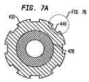
本発明によるリテーナのプッシャー432の例示的な実施形態の断面が、図7Aに示されている。プッシャー432は、8つの凹部440を備えている点を除けば、前述のプッシャー32,132,232と同様である。しかし、プッシャー432は、弁のステント部分の端に形成されたV字状接合部の数に依存して、どのような数の凹部、例えば、2,4,6,8,9,10,12,または16個の凹部を備えていてもよいことを理解されたい。 A cross-section of an exemplary embodiment of a
図7Bを参照すると、凹部440aの例示的な実施形態の拡大断面が示されている。凹部440aは、アンダーカットを備える断面形状を有している点を除けば、図7Aに示されている凹部440と同様である。この場合、リテーナの略長手方向に延在する各横縁441は、90°未満の角度でプッシャー432の外面から内方に突出している。凹部440aにこのようなアンダーカットを備えさせることによって、弁のステント部分のV字状接合部を把持する凹部の能力が高められる。その結果、プッシャーおよびホルダーが弁をリテーナに係止するために互いに向かって移動するとき、V字状接合部と凹部との間に干渉が生じ、ステント部分が凹部から脱落しないように阻止するのを助長し、これによって、ホルダーとプッシャーが互いに接近して配置されている間の弁の時期尚早の展開を阻止することに役立つことになる。 Referring to FIG. 7B, an enlarged cross section of an exemplary embodiment of the
凹部440aの長手方向長さの任意の部分がアンダーカットされ、該凹部の長さの残りがアンダーカットされていなくてもよい(すなわち、横縁441のアンダーカットされていない部分が、少なくとも90°の角度でプッシャー432の外面から内方に突出していてもよい)。例えば、各凹部440aは、凹部の長手方向長さの最遠位側の10〜20%のみにアンダーカットされた横縁441を有していてもよい。実質的に長手方向に配向した横縁、例えば、図3A、図3Bおよび図4に示されている凹部を有するリテーナ実施形態では、弁がリテーナに係合するとき、凹部の閉端および長手方向長さの最遠位側の10〜20%のみが弁のステント部分のV字状接合部と接触するので、これらが、アンダーカットが凹部のステント把持能力を高める凹部の唯一の部分である。 Any portion of the longitudinal length of the
図8を参照すると、本発明による折畳み可能な人工心臓弁用の例示的な経大腿送達装置510が示されている。送達装置510は、前述の送達装置10と同様であるが、プッシャーおよびホルダーが互いに対して摺動可能になっているリテーナ230と同様のリテーナを備えている。 Referring to FIG. 8, an exemplary
送達装置510のリテーナ530は、プッシャー532を備えている。プッシャー532は、ハブ520を近位端に有する内側シャフト526に固設されている。リテーナ530のホルダー534は、ホルダーシャフト529に固設されている。ホルダーシャフト529は、内側シャフト526の管腔内を通って、近位ハブ525まで延在している。図8に示されている実施形態では、ホルダー534は、弁のステント部分の近位端をホルダー534とプッシャー532との間に捕捉し、これによって、弁をリテーナ530に組み込むために、プッシャー532に対して長手方向に摺動可能になっている。プッシャー532の凹部およびホルダー534のリブは、図8に示されていないが、プッシャーおよびホルダーは、本明細書に開示されている凹部構成およびリブ構成のいずれを有していてもよい。 The
送達装置510は、遠位シース524を備えている。遠位シース524は、組立状態にある折畳み可能な人工心臓弁506を中心シャフト527の周りに受け入れるように構成された区画523を包囲している。中心シャフト527は、送達装置の遠位端とホルダーシャフト529内のある箇所との間に延在している。中心シャフト527は、送達装置の遠位チップとホルダーシャフト529との間に固定した接続をもたらすようになっているとよい。中心シャフト527は、送達装置の遠位チップから、ホルダーシャフト529内の(ホルダー534に隣接する)箇所に近位側に延在していてもよいし、または送達装置の近位端までずっと延在していてもよい。中心シャフト527は、ガイドワイヤ(図示せず)が挿通する管腔を有しているとよい。前述のリテーナ230と同じように、ユーザーは、ホルダーをプッシャーに向かって近位側に摺動させることによって、弁506のステント部分のV字状接合部をプッシャー532の凹部とホルダー534のリブとの間に捕捉させることによって、弁506を区画523内に装填するとよい。
弁506のステント部分の近位端がプッシャー532とホルダー534との間に捕捉された状態で、ユーザーは、ハブ520内に配置された係止ピン519をロック位置に移動させるとよい。ロック位置では、係止ピン519は、内側シャフト526をホルダーシャフト529に一時的に固定し、プッシャー532とホルダー534との相対的位置を固定することになる。弁506を展開させるために、ユーザーは、最初、ハブ521を近位側に摺動させることによって、遠位シース524を区画523の周りから引き出すとよい。続いて、ユーザーは、係止ピン519を解除位置に移動させ、ホルダーシャフト529、およびそれに付随するホルダー534を遠位側に摺動させ、弁506をリテーナ530から離脱させるとよい。その結果、弁は、自己拡張し、これによって、リテーナから離脱することになる。 With the proximal end of the stent portion of the
図9は、本発明による折畳み可能な人工心臓弁用の他の例示的経大腿送達装置610を示している。送達装置610の構造および機能は、以下の点、すなわち、ホルダーがプッシャーに対して摺動可能になっているというよりは、むしろプッシャー632がホルダー634に対して長手方向に摺動可能になっており、これによって、ユーザーが人工弁のステント部分をリテーナ630内に捕捉することができるようになっている点を除けば、前述の送達装置510の構造および機能と全ての点において同様である。所定の実施形態において、プッシャー、ホルダー、またはこれらの両方の構成要素が、摺動可能になるように構成されるかまたは固定されるように構成されるかは、それぞれのハブがどのように操作ハンドル(図示せず)に取り付けられているかに依存している。人工弁のステント部分は、プッシャー、ホルダー、またはこれらの両方の構成要素が摺動可能になるように構成されているかどうかに関わらず、同じように、プッシャーとホルダーとの間に捕捉させることが可能である。 FIG. 9 illustrates another exemplary
図10Aおよび図10Bを参照すると、本発明による折畳み可能な人工心臓弁用のさらに他の例示的な経大腿送達装置710が示されている。送達装置710は、以下の点、すなわち、プッシャー732が、複数の離間した凹部ではなく、その全周に連続的に延在する環状壁741を有する単一凹部740を備えている点を除けば、図8および図9を参照して前述した送達装置510,610と同様である。弁が送達装置710内に組み込まれるとき、弁のステント部分のV字状接合部は、半径方向外方に拡がらないように、環状壁741によって保持されることになる。プッシャー732の環状壁741の存在によって、送達装置710内への弁の装填中にプッシャー732が弁の近位端を保持するのが容易になる。プッシャー732、ホルダー734、またはこれらの両方の構成要素は、互いに摺動可能になっていてもよいし、または固定されていてもよい。ホルダー734のリブが図10Aに示されていないが、ホルダーは、本明細書に開示されているリブ構成のいずれを有していてもよい。 Referring to FIGS. 10A and 10B, yet another exemplary
本発明の他の実施形態によるリテーナ830が、図11に示されている。リテーナ830は、以下の点、すなわち、リブ850がホルダーの外面から半径方向外方に延在しておらず、ホルダー834に取り付けられた円錐端836から近位側に延在している点を除けば、前述の移動可能なプッシャーおよび/またはホルダーを有するリテーナ230,530,630,730と同様である。プッシャー832の凹部は、図11の特定の断面には示されていないが、ホルダーは、折畳み可能な人工弁のステント部分のV字状接合部を受け入れるように構成された(保持縁833から近位側に延在する)凹部を有しているとよい。プッシャー832、ホルダー834、またはこれらの両方の構成要素は、互いに摺動可能になっていてもよいし、または固定されていてもよい。 A
図12を参照すると、折畳み可能な人工心臓弁906用の例示的な経心尖送達装置910は、心臓弁を目標箇所に送達し、該心臓弁を該目標箇所において展開するためのカテーテルアセンブリ916を有している。送達装置910は、近位端912から遠位端914に延在している。カテーテルアセンブリ916は、組立状態にある折畳み可能な人工心臓弁を区画923内に受け入れるように構成されている。区画923は、支持シャフト928の周りに画定されており、遠位シース924によって覆われている。 Referring to FIG. 12, an exemplary
支持シャフト928が、支持シャフトの遠位端に固定されたホルダー934から支持シャフトの近位端に固定されたリテーナ911に延在している。リテーナ911は、その近位端にハブ921を有する外側シャフト922に接続されている。ホルダー934およびプッシャー932は、折畳み可能な人工弁を支持シャフト928の周りに画定された区画923内に保持するように構成されている。プッシャー932は、プッシャーシャフト929に固設されているとよい。プッシャーシャフト929は、支持シャフト928および外側シャフト922内を通って、ハブ925に延在している。内側シャフト926は、その近位端のハブ920から、プッシャーシャフト929内を通って、送達装置910の遠位端914における無傷チップ931への接続部に延在している。 A support shaft 928 extends from a holder 934 secured to the distal end of the support shaft to a
遠位シース924は、区画923を包囲しており、該区画内に配置された折畳み可能な人工弁906を選択的に覆おうかまたは露出させるために、支持シャフト928に対して摺動可能になっている。遠位シース924は、その遠位端においてチップ931に固設されている。遠位シース924の近位端915は、遠位シースが、図12に示されているように、区画923を完全に覆っているとき、リテーナ911の円錐面917に当接しており、区画923が少なくとも部分的に露出するとき、円錐面917から離間することになる。
図12に示されている実施形態では、プッシャー932および/またはホルダー934は、弁906のステント部分の遠位端をそれらの間に捕捉するために、互いに対して摺動可能になっている。プッシャー932の凹部およびホルダー934のリブが図12に示されていないが、プッシャーおよびホルダーは、本明細書に開示されている凹部構成およびリブ構成のいずれを有していてもよい。前述の送達装置510,610と同様、ユーザーは、プッシャー932および/またはホルダー934を互いに向かって長手方向に摺動させることによって、弁のステント部分のV字状接合部をプッシャー932の凹部とホルダー934のリブとの間に捕捉させることによって、弁906を区画923内に装填させるとよい。 In the embodiment shown in FIG. 12,
送達装置910は、係止ピン919を備えているとよい。係止ピン919は、ロック位置において、外側シャフト922(それに伴って、支持シャフト928)をプッシャーシャフト929に一時的に固定し、これによって、プッシャー932およびホルダー934の相対的位置を固定するように構成されている。弁906のステント部分の遠位端がプッシャーとホルダーとの間に捕捉されている状態で、ユーザーは、係止ピン919をロック位置に移動させ、プッシャーおよびホルダーの相対的位置を固定するとよい。
弁906を展開させるために、ユーザーは、最初、内側シャフト926を外側シャフト922およびプッシャーシャフト929に対して遠位側に摺動させることによって、遠位シース924を区画923の周りから引き出すとよい。続いて、ユーザーは、係止ピン919を解除位置に移動させ、プッシャー932およびホルダー934を長手方向において互いに離れる方に摺動させ、弁906をリテーナ930内から離脱させるとよい。その結果、弁は、自己拡張することができ、これによって、送達装置910から離脱することになる。 To deploy the
図13を参照すると、本発明の他の実施形態によるリテーナ1030が示されている。リテーナ1030は、従来の人工弁のステント部分、例えば、図1に示されているステント部分6を保持し、位置合せするように構成されている。リテーナ1030は、弁がリテーナから遠位側に延在するようになっている経大腿送達装置、例えば、前述の送達装置10、または弁がリテーナ―から近位側に延在するようになっている経心尖送達装置、例えば、前述の送達装置910のいずれに組み込まれてもよい。 Referring to FIG. 13, a
リテーナ1030は、内側シャフト1026に固設された保持部1032を備えている。この保持部は、従来の弁の保持部材、例えば、図1に示されている保持部材7を受け入れるように構成された複数の受入れ部1035を備えている。リテーナ1030は、保持部1032に固設されたスペーサ部1034も備えている。スペーサ部は、長手方向に延在する複数のリブ1050を備えている。各隣接リブ対は、それらの間に溝1052を画定している。リブ1050は、好ましくは、スペーサ部1034の周方向において均一に離間している。 The
患者内に送達する目的で、従来の人工弁のステント部分をリテーナ1030内に装填するために、ユーザーは、弁の保持部材を受入れ部1035内に挿入し、ステントの大動脈端のV字状接合部をそれぞれの溝1052内に挿入するとよい。受入れ部1035と長手方向において真っ直ぐに並んでいる溝1052は、保持部材と長手方向において真っ直ぐに並んだV字状の接合部を受け入れることができる。 To load the stent portion of a conventional prosthetic valve into the
従来の送達システムでは、従来の人工弁のステント部分は、患者の所望箇所への弁の送達中に捩じれる可能性があり、ステント支柱が、弁を覆っている遠位シースに固着し、支柱を変形または損傷させ、および/または弁を鞘出しするのに必要な力を増大させる可能性がある。従来のリテーナと比較し、リテーナ1030は、患者内への弁の送達中、ステント支柱のV字状接合部を真っ直ぐに保持することができ、これによって、弁への損傷を防ぎ、鞘出しおよび展開に必要な力を最小限に抑えることができる。 In conventional delivery systems, the stent portion of a conventional prosthetic valve can be twisted during delivery of the valve to the desired location on the patient, and the stent struts can be secured to the distal sheath that covers the valve. May be deformed or damaged and / or increase the force required to unsheath the valve. Compared to a conventional retainer, the
折畳み可能なステント構造を有する人工弁を展開させるための保持に関連して、種々のリテーナ実施形態を説明してきたが、これらのリテーナ実施形態の全てが、他の目的に用いられてもよい。特に、リテーナの種々の実施形態は、弁構造体を含んでいない従来の折畳み可能なステントを保持するために用いられてもよい。 Although various retainer embodiments have been described in connection with retention for deploying a prosthetic valve having a collapsible stent structure, all of these retainer embodiments may be used for other purposes. In particular, various embodiments of the retainer may be used to hold a conventional foldable stent that does not include a valve structure.
人工弁の弁輪端が最初に展開される特定の実施形態を参照して、本発明を説明してきたが、本発明は、弁の大動脈端が最初に展開する実施形態も考慮していることを理解されたい。このような実施形態(図示せず)では、弁のステント部分の弁輪端がリテーナに係合され、ステントの大動脈端が、リテーナから離れており、最初に鞘出しされるようになっているとよい。 Although the present invention has been described with reference to a particular embodiment in which the annulus end of the prosthetic valve is first deployed, the present invention also contemplates embodiments in which the aortic end of the valve is first deployed. I want you to understand. In such an embodiment (not shown), the annulus end of the stent portion of the valve is engaged with the retainer so that the aortic end of the stent is remote from the retainer and is initially sheathed. Good.
特定の実施形態を参照して、本発明をここに説明してきたが、これらの実施形態は、本発明の原理および応用の単なる例示にすぎないことを理解されたい。従って、例示的な実施形態に対して多くの修正がなされてもよいこと、および添付の請求項に記載されている本発明の精神および範囲から逸脱することなく、他の構成が考案されてもよいことを理解されたい。 Although the invention herein has been described with reference to particular embodiments, it is to be understood that these embodiments are merely illustrative of the principles and applications of the present invention. Accordingly, many modifications may be made to an exemplary embodiment and other configurations may be devised without departing from the spirit and scope of the invention as set forth in the appended claims. Please understand that it is good.
種々の従属請求項および該請求項に記載されている特徴は、元の請求項に記載されているのと異なる方法によって組み合わされてもよいことを理解されたい。また、個々の実施形態に関連して記載されている特徴は、記載されている実施形態の他の特徴と共有されてもよいことも理解されたい。 It should be understood that the various dependent claims and the features recited in the claims may be combined in different ways than those recited in the original claim. It should also be understood that features described in connection with individual embodiments may be shared with other features of the described embodiments.
本発明は、広い産業上の利用可能性、例えば、制限されるものではないが、折畳み可能な人工心臓弁のための送達装置および折畳み可能な人工心臓弁を送達する方法を享有するものである。 The present invention enjoys wide industrial applicability, such as, but not limited to, a delivery device for a foldable prosthetic heart valve and a method of delivering a foldable prosthetic heart valve. .
Claims (19)
Translated fromJapanese主シャフトを備えるカテーテルアセンブリであって、区画が前記主シャフトの周りに画定されており、前記区画は、組立状態にある前記弁を受け入れるように構成されており、前記カテーテルアセンブリは、前記区画および前記弁を選択的に覆うかまたは露出させるように構成された遠位シースをさらに備えており、前記遠位シースは、少なくとも前記区画を覆っているとき、前記主シャフトの周りに延在するようになっているカテーテルアセンブリと、
リテーナであって、
少なくとも1つの凹部を保持縁に有するプッシャーであって、前記凹部は、前記弁のステント部分の端の接合部を受け入れるように適合されているプッシャーと、
前記弁のステント部分のセル開口内に嵌合するように構成された少なくとも1つの細長リブを有するホルダーと、
を備えているリテーナと、
を備えていることを特徴とする、送達装置。In a delivery device for a foldable prosthetic heart valve,
A catheter assembly comprising a main shaft, wherein a compartment is defined around the main shaft, the compartment being configured to receive the valve in an assembled state, the catheter assembly comprising the compartment and A distal sheath configured to selectively cover or expose the valve further includes the distal sheath extending around the main shaft when covering at least the compartment. A catheter assembly,
A retainer,
A pusher having at least one recess at a retaining edge, the recess being adapted to receive a joint at an end of a stent portion of the valve;
A holder having at least one elongated rib configured to fit within a cell opening in the stent portion of the valve;
A retainer comprising:
A delivery device comprising:
主シャフトを備えるカテーテルアセンブリであって、区画が前記主シャフトの周りに画定されており、前記区画は、組立状態にある弁を受け入れるように構成されており、前記カテーテルアセンブリは、前記区画および前記弁を選択的に覆うかまたは露出させるように適合された遠位シースをさらに備えており、前記遠位シースは、少なくとも前記区画を覆っているとき、前記主シャフトの周りに延在しているカテーテルアセンブリと、
リテーナであって、
前記主シャフトに固設されており、前記弁のステント部分の端から延在する保持部材を受け入れるように構成された複数の受入れ部を備えている保持部と、
複数の周方向に互いに離間した細長リブを有するスペーサ部であって、各隣接リブ対は、それらの間に溝を画定しており、各溝は、前記弁の前記ステント部分の端の接合部を受け入れるように構成されているスペーサ部と、
を備えているリテーナと、
を備えていることを特徴とする、送達装置。In a delivery device for a foldable prosthetic heart valve,
A catheter assembly comprising a main shaft, wherein a compartment is defined around the main shaft, the compartment being configured to receive an assembled valve, the catheter assembly comprising the compartment and the A distal sheath adapted to selectively cover or expose a valve, the distal sheath extending around the main shaft when covering at least the compartment A catheter assembly;
A retainer,
A holding portion fixed to the main shaft and comprising a plurality of receiving portions configured to receive a holding member extending from an end of a stent portion of the valve;
A spacer portion having a plurality of circumferentially spaced elongated ribs, each adjacent rib pair defining a groove therebetween, each groove being a joint at the end of the stent portion of the valve A spacer portion configured to receive the
A retainer comprising:
A delivery device comprising:
送達装置を準備するステップであって、前記送達装置は、区画が周りに画定されている主シャフトと、前記区画を選択的に覆うかまたは露出させるように構成された遠位シースであって、少なくとも前記区画を覆っているとき、前記主シャフトの周りに延在するようになっている、遠位シースと、プッシャーおよびホルダーを備えているリテーナであって、前記プッシャーは、その保持縁に少なくとも1つの凹部を有しており、前記ホルダーは、少なくとも1つの細長リブを有しているリテーナとを備えているステップと、
ステント部分を有する折畳み可能な人工心臓弁を前記区画内に取り付けるステップであって、前記ステント部分は、その端に複数の接合部および前記ステント部分に画定された複数のセル開口を備えており、前記弁は、前記接合部の少なくとも1つが前記少なくとも1つの凹部内に位置決めされ、前記少なくとも1つのリブが前記セル開口の少なくとも1つに位置決めされるように取り付けられるようになっているステップと、
前記区画および前記弁を覆うように前記遠位シースを移動させるステップと、
前記送達装置を患者内に挿入し、前記弁を目的箇所に位置決めするステップと、
前記遠位シースを移動させ、前記区画および前記弁を露出させることによって、前記弁を展開させるステップと、
を含んでいることを特徴とする、方法。In a method of delivering a foldable prosthetic heart valve,
Providing a delivery device, the delivery device comprising a main shaft having a compartment defined therein and a distal sheath configured to selectively cover or expose the compartment; A retainer comprising a distal sheath, a pusher and a holder, adapted to extend around the main shaft when covering at least the compartment, the pusher at least on its retaining edge Having a recess, the holder comprising a retainer having at least one elongated rib;
Attaching a foldable prosthetic heart valve having a stent portion within the compartment, the stent portion comprising a plurality of joints at its ends and a plurality of cell openings defined in the stent portion; The valve is adapted to be mounted such that at least one of the joints is positioned in the at least one recess and the at least one rib is positioned in at least one of the cell openings;
Moving the distal sheath over the compartment and the valve;
Inserting the delivery device into a patient and positioning the valve at a target location;
Deploying the valve by moving the distal sheath to expose the compartment and the valve;
A method characterized by comprising:
Applications Claiming Priority (3)
| Application Number | Priority Date | Filing Date | Title |
|---|---|---|---|
| US38401410P | 2010-09-17 | 2010-09-17 | |
| US61/384,014 | 2010-09-17 | ||
| PCT/US2011/001596WO2012036740A2 (en) | 2010-09-17 | 2011-09-16 | Retainers for transcatheter heart valve delivery systems |
Publications (1)
| Publication Number | Publication Date |
|---|---|
| JP2013540481Atrue JP2013540481A (en) | 2013-11-07 |
Family
ID=44736024
Family Applications (1)
| Application Number | Title | Priority Date | Filing Date |
|---|---|---|---|
| JP2013529124AWithdrawnJP2013540481A (en) | 2010-09-17 | 2011-09-16 | Retainer for transcatheter heart valve delivery system |
Country Status (7)
| Country | Link |
|---|---|
| US (2) | US9439795B2 (en) |
| EP (1) | EP2616006B1 (en) |
| JP (1) | JP2013540481A (en) |
| AU (1) | AU2011302639B2 (en) |
| BR (1) | BR112013006302A2 (en) |
| CR (1) | CR20130164A (en) |
| WO (1) | WO2012036740A2 (en) |
Cited By (4)
| Publication number | Priority date | Publication date | Assignee | Title |
|---|---|---|---|---|
| JP2014516676A (en)* | 2011-05-12 | 2014-07-17 | メドトロニック,インコーポレイテッド | Delivery catheter system with micro and macro movement control devices |
| JP2017176666A (en)* | 2016-03-31 | 2017-10-05 | 日本ゼオン株式会社 | Stent delivery system |
| JP2020526272A (en)* | 2017-06-30 | 2020-08-31 | エドワーズ ライフサイエンシーズ コーポレイションEdwards Lifesciences Corporation | Docking station for transcatheter valves |
| US12295869B2 (en) | 2017-06-30 | 2025-05-13 | Edwards Lifesciences Corporation | Lock and release mechanisms for trans-catheter implantable devices |
Families Citing this family (112)
| Publication number | Priority date | Publication date | Assignee | Title |
|---|---|---|---|---|
| US11278398B2 (en) | 2003-12-23 | 2022-03-22 | Boston Scientific Scimed, Inc. | Methods and apparatus for endovascular heart valve replacement comprising tissue grasping elements |
| US7959666B2 (en)* | 2003-12-23 | 2011-06-14 | Sadra Medical, Inc. | Methods and apparatus for endovascularly replacing a heart valve |
| US8603160B2 (en) | 2003-12-23 | 2013-12-10 | Sadra Medical, Inc. | Method of using a retrievable heart valve anchor with a sheath |
| US9526609B2 (en) | 2003-12-23 | 2016-12-27 | Boston Scientific Scimed, Inc. | Methods and apparatus for endovascularly replacing a patient's heart valve |
| US20120041550A1 (en) | 2003-12-23 | 2012-02-16 | Sadra Medical, Inc. | Methods and Apparatus for Endovascular Heart Valve Replacement Comprising Tissue Grasping Elements |
| US8828078B2 (en) | 2003-12-23 | 2014-09-09 | Sadra Medical, Inc. | Methods and apparatus for endovascular heart valve replacement comprising tissue grasping elements |
| US20050137687A1 (en) | 2003-12-23 | 2005-06-23 | Sadra Medical | Heart valve anchor and method |
| US7381219B2 (en) | 2003-12-23 | 2008-06-03 | Sadra Medical, Inc. | Low profile heart valve and delivery system |
| US8840663B2 (en) | 2003-12-23 | 2014-09-23 | Sadra Medical, Inc. | Repositionable heart valve method |
| DE102005003632A1 (en) | 2005-01-20 | 2006-08-17 | Fraunhofer-Gesellschaft zur Förderung der angewandten Forschung e.V. | Catheter for the transvascular implantation of heart valve prostheses |
| US20070213813A1 (en) | 2005-12-22 | 2007-09-13 | Symetis Sa | Stent-valves for valve replacement and associated methods and systems for surgery |
| EP1988851A2 (en)* | 2006-02-14 | 2008-11-12 | Sadra Medical, Inc. | Systems and methods for delivering a medical implant |
| US7896915B2 (en) | 2007-04-13 | 2011-03-01 | Jenavalve Technology, Inc. | Medical device for treating a heart valve insufficiency |
| BR112012021347A2 (en) | 2008-02-26 | 2019-09-24 | Jenavalve Tecnology Inc | stent for positioning and anchoring a valve prosthesis at an implantation site in a patient's heart |
| US9044318B2 (en) | 2008-02-26 | 2015-06-02 | Jenavalve Technology Gmbh | Stent for the positioning and anchoring of a valvular prosthesis |
| EP3238661B1 (en) | 2008-10-10 | 2019-05-22 | Boston Scientific Scimed, Inc. | Medical devices and delivery systems for delivering medical devices |
| US8870950B2 (en) | 2009-12-08 | 2014-10-28 | Mitral Tech Ltd. | Rotation-based anchoring of an implant |
| US20110224785A1 (en) | 2010-03-10 | 2011-09-15 | Hacohen Gil | Prosthetic mitral valve with tissue anchors |
| US8579964B2 (en) | 2010-05-05 | 2013-11-12 | Neovasc Inc. | Transcatheter mitral valve prosthesis |
| US10856978B2 (en) | 2010-05-20 | 2020-12-08 | Jenavalve Technology, Inc. | Catheter system |
| WO2011147849A1 (en) | 2010-05-25 | 2011-12-01 | Jenavalve Technology Inc. | Prosthetic heart valve and transcatheter delivered endoprosthesis comprising a prosthetic heart valve and a stent |
| US9387077B2 (en) | 2010-05-27 | 2016-07-12 | Medtronic Vascular Galway | Catheter assembly with prosthesis crimping and prosthesis retaining accessories |
| US11653910B2 (en) | 2010-07-21 | 2023-05-23 | Cardiovalve Ltd. | Helical anchor implantation |
| US9763657B2 (en) | 2010-07-21 | 2017-09-19 | Mitraltech Ltd. | Techniques for percutaneous mitral valve replacement and sealing |
| US10130470B2 (en) | 2010-08-17 | 2018-11-20 | St. Jude Medical, Llc | Sleeve for facilitating movement of a transfemoral catheter |
| AU2011300644B2 (en) | 2010-09-10 | 2015-08-20 | Symetis Sa | Valve replacement devices and a system comprising the valve replacement device and a delivery device therefor |
| JP2013540481A (en) | 2010-09-17 | 2013-11-07 | セント・ジュード・メディカル,カーディオロジー・ディヴィジョン,インコーポレイテッド | Retainer for transcatheter heart valve delivery system |
| US9308087B2 (en) | 2011-04-28 | 2016-04-12 | Neovasc Tiara Inc. | Sequentially deployed transcatheter mitral valve prosthesis |
| US9554897B2 (en) | 2011-04-28 | 2017-01-31 | Neovasc Tiara Inc. | Methods and apparatus for engaging a valve prosthesis with tissue |
| US8998976B2 (en) | 2011-07-12 | 2015-04-07 | Boston Scientific Scimed, Inc. | Coupling system for medical devices |
| EP2736450A1 (en) | 2011-07-28 | 2014-06-04 | St. Jude Medical, Inc. | Expandable radiopaque marker for transcatheter aortic valve implantation |
| US8852272B2 (en) | 2011-08-05 | 2014-10-07 | Mitraltech Ltd. | Techniques for percutaneous mitral valve replacement and sealing |
| EP2739214B1 (en) | 2011-08-05 | 2018-10-10 | Cardiovalve Ltd | Percutaneous mitral valve replacement and sealing |
| WO2013021374A2 (en) | 2011-08-05 | 2013-02-14 | Mitraltech Ltd. | Techniques for percutaneous mitral valve replacement and sealing |
| US20140324164A1 (en) | 2011-08-05 | 2014-10-30 | Mitraltech Ltd. | Techniques for percutaneous mitral valve replacement and sealing |
| GB2500881A (en)* | 2012-03-30 | 2013-10-09 | Cook Medical Technologies Llc | Stent holding structure for introducers |
| US9345573B2 (en) | 2012-05-30 | 2016-05-24 | Neovasc Tiara Inc. | Methods and apparatus for loading a prosthesis onto a delivery system |
| US9480561B2 (en) | 2012-06-26 | 2016-11-01 | St. Jude Medical, Cardiology Division, Inc. | Apparatus and method for aortic protection and TAVI planar alignment |
| US9918837B2 (en) | 2012-06-29 | 2018-03-20 | St. Jude Medical, Cardiology Division, Inc. | System to assist in the release of a collapsible stent from a delivery device |
| JP6057584B2 (en)* | 2012-07-24 | 2017-01-11 | 株式会社カネカ | Self-expanding stent delivery system and manufacturing method thereof |
| US9687373B2 (en)* | 2012-12-21 | 2017-06-27 | Cook Medical Technologies Llc | Systems and methods for securing and releasing a portion of a stent |
| CN103083122B (en)* | 2013-01-21 | 2015-11-04 | 北京华脉泰科医疗器械有限公司 | A kind of fixture of overlay film frame |
| US20150351906A1 (en) | 2013-01-24 | 2015-12-10 | Mitraltech Ltd. | Ventricularly-anchored prosthetic valves |
| CN103126739B (en)* | 2013-01-31 | 2016-05-04 | 北京华脉泰科医疗器械有限公司 | A kind of conveying device of overlay film frame |
| US9572665B2 (en) | 2013-04-04 | 2017-02-21 | Neovasc Tiara Inc. | Methods and apparatus for delivering a prosthetic valve to a beating heart |
| DE102013104565B3 (en)* | 2013-05-03 | 2014-10-16 | Jotec Gmbh | Pusher assembly for a delivery system for a self-expanding vascular graft and a delivery system |
| CN105491978A (en) | 2013-08-30 | 2016-04-13 | 耶拿阀门科技股份有限公司 | Radially collapsible frame for a prosthetic valve and method for manufacturing such a frame |
| EP3174502B1 (en) | 2014-07-30 | 2022-04-06 | Cardiovalve Ltd | Apparatus for implantation of an articulatable prosthetic valve |
| DE202014104330U1 (en)* | 2014-09-12 | 2015-12-16 | Pfm Medical Ag | Device for inserting a medical implant into a human or animal body |
| JP2017530814A (en) | 2014-10-13 | 2017-10-19 | シメティス・ソシエテ・アノニムSymetis Sa | Catheter delivery system for stent valves |
| US9433520B2 (en) | 2015-01-29 | 2016-09-06 | Intact Vascular, Inc. | Delivery device and method of delivery |
| US9375336B1 (en) | 2015-01-29 | 2016-06-28 | Intact Vascular, Inc. | Delivery device and method of delivery |
| US9974651B2 (en) | 2015-02-05 | 2018-05-22 | Mitral Tech Ltd. | Prosthetic valve with axially-sliding frames |
| CN110141399B (en) | 2015-02-05 | 2021-07-27 | 卡迪尔维尔福股份有限公司 | Prosthetic valve with axial sliding frame |
| EP3270825B1 (en) | 2015-03-20 | 2020-04-22 | JenaValve Technology, Inc. | Heart valve prosthesis delivery system |
| US10376363B2 (en)* | 2015-04-30 | 2019-08-13 | Edwards Lifesciences Cardiaq Llc | Replacement mitral valve, delivery system for replacement mitral valve and methods of use |
| US10709555B2 (en) | 2015-05-01 | 2020-07-14 | Jenavalve Technology, Inc. | Device and method with reduced pacemaker rate in heart valve replacement |
| CA3007660A1 (en) | 2015-12-15 | 2017-06-22 | Neovasc Tiara Inc. | Transseptal delivery system |
| CN106913408B (en)* | 2015-12-28 | 2018-10-26 | 先健科技(深圳)有限公司 | Transport system and intraluminal stent system |
| US10993824B2 (en) | 2016-01-01 | 2021-05-04 | Intact Vascular, Inc. | Delivery device and method of delivery |
| US10433952B2 (en) | 2016-01-29 | 2019-10-08 | Neovasc Tiara Inc. | Prosthetic valve for avoiding obstruction of outflow |
| US10531866B2 (en) | 2016-02-16 | 2020-01-14 | Cardiovalve Ltd. | Techniques for providing a replacement valve and transseptal communication |
| EP3213714A1 (en)* | 2016-03-03 | 2017-09-06 | Biotronik AG | Insertion catheter and catheter assembly |
| US10667907B2 (en) | 2016-05-13 | 2020-06-02 | St. Jude Medical, Cardiology Division, Inc. | Systems and methods for device implantation |
| WO2017195125A1 (en) | 2016-05-13 | 2017-11-16 | Jenavalve Technology, Inc. | Heart valve prosthesis delivery system and method for delivery of heart valve prosthesis with introducer sheath and loading system |
| US10201416B2 (en) | 2016-05-16 | 2019-02-12 | Boston Scientific Scimed, Inc. | Replacement heart valve implant with invertible leaflets |
| US20190231525A1 (en)* | 2016-08-01 | 2019-08-01 | Mitraltech Ltd. | Minimally-invasive delivery systems |
| CA3031187A1 (en) | 2016-08-10 | 2018-02-15 | Cardiovalve Ltd. | Prosthetic valve with concentric frames |
| CA3042588A1 (en) | 2016-11-21 | 2018-05-24 | Neovasc Tiara Inc. | Methods and systems for rapid retraction of a transcatheter heart valve delivery system |
| US10376396B2 (en) | 2017-01-19 | 2019-08-13 | Covidien Lp | Coupling units for medical device delivery systems |
| US10653523B2 (en) | 2017-01-19 | 2020-05-19 | 4C Medical Technologies, Inc. | Systems, methods and devices for delivery systems, methods and devices for implanting prosthetic heart valves |
| US10561495B2 (en) | 2017-01-24 | 2020-02-18 | 4C Medical Technologies, Inc. | Systems, methods and devices for two-step delivery and implantation of prosthetic heart valve |
| WO2018138658A1 (en) | 2017-01-27 | 2018-08-02 | Jenavalve Technology, Inc. | Heart valve mimicry |
| US12029647B2 (en) | 2017-03-07 | 2024-07-09 | 4C Medical Technologies, Inc. | Systems, methods and devices for prosthetic heart valve with single valve leaflet |
| US12036113B2 (en) | 2017-06-14 | 2024-07-16 | 4C Medical Technologies, Inc. | Delivery of heart chamber prosthetic valve implant |
| US11660218B2 (en) | 2017-07-26 | 2023-05-30 | Intact Vascular, Inc. | Delivery device and method of delivery |
| US10537426B2 (en) | 2017-08-03 | 2020-01-21 | Cardiovalve Ltd. | Prosthetic heart valve |
| US10575948B2 (en) | 2017-08-03 | 2020-03-03 | Cardiovalve Ltd. | Prosthetic heart valve |
| US11246704B2 (en) | 2017-08-03 | 2022-02-15 | Cardiovalve Ltd. | Prosthetic heart valve |
| US11793633B2 (en) | 2017-08-03 | 2023-10-24 | Cardiovalve Ltd. | Prosthetic heart valve |
| US12064347B2 (en) | 2017-08-03 | 2024-08-20 | Cardiovalve Ltd. | Prosthetic heart valve |
| US10888421B2 (en) | 2017-09-19 | 2021-01-12 | Cardiovalve Ltd. | Prosthetic heart valve with pouch |
| CA3073834A1 (en) | 2017-08-25 | 2019-02-28 | Neovasc Tiara Inc. | Sequentially deployed transcatheter mitral valve prosthesis |
| US20190083242A1 (en) | 2017-09-19 | 2019-03-21 | Cardiovalve Ltd. | Systems and methods for implanting a prosthetic valve within a native heart valve |
| US9895226B1 (en) | 2017-10-19 | 2018-02-20 | Mitral Tech Ltd. | Techniques for use with prosthetic valve leaflets |
| GB201720803D0 (en) | 2017-12-13 | 2018-01-24 | Mitraltech Ltd | Prosthetic Valve and delivery tool therefor |
| GB201800399D0 (en) | 2018-01-10 | 2018-02-21 | Mitraltech Ltd | Temperature-control during crimping of an implant |
| CN117481869A (en) | 2018-01-25 | 2024-02-02 | 爱德华兹生命科学公司 | Delivery system for assisting in recapture and repositioning of replacement valves after deployment |
| US10932931B2 (en) | 2018-03-13 | 2021-03-02 | Medtronic Vascular, Inc. | Medical device delivery system including a support member |
| US11123209B2 (en) | 2018-04-12 | 2021-09-21 | Covidien Lp | Medical device delivery |
| US10786377B2 (en)* | 2018-04-12 | 2020-09-29 | Covidien Lp | Medical device delivery |
| US11071637B2 (en) | 2018-04-12 | 2021-07-27 | Covidien Lp | Medical device delivery |
| US11413176B2 (en) | 2018-04-12 | 2022-08-16 | Covidien Lp | Medical device delivery |
| US11857441B2 (en) | 2018-09-04 | 2024-01-02 | 4C Medical Technologies, Inc. | Stent loading device |
| CN113271890B (en) | 2018-11-08 | 2024-08-30 | 内奥瓦斯克迪亚拉公司 | Ventricular deployment of transcatheter mitral valve prosthesis |
| CA3132873A1 (en) | 2019-03-08 | 2020-09-17 | Neovasc Tiara Inc. | Retrievable prosthesis delivery system |
| CA3135753C (en) | 2019-04-01 | 2023-10-24 | Neovasc Tiara Inc. | Controllably deployable prosthetic valve |
| US11491006B2 (en) | 2019-04-10 | 2022-11-08 | Neovasc Tiara Inc. | Prosthetic valve with natural blood flow |
| US11452628B2 (en) | 2019-04-15 | 2022-09-27 | 4C Medical Technologies, Inc. | Loading systems for collapsible prosthetic heart valve devices and methods thereof |
| US11779742B2 (en) | 2019-05-20 | 2023-10-10 | Neovasc Tiara Inc. | Introducer with hemostasis mechanism |
| JP7520897B2 (en) | 2019-06-20 | 2024-07-23 | ニオバスク ティアラ インコーポレイテッド | Thin prosthetic mitral valve |
| US11413174B2 (en) | 2019-06-26 | 2022-08-16 | Covidien Lp | Core assembly for medical device delivery systems |
| WO2021144203A1 (en)* | 2020-01-16 | 2021-07-22 | Biotronik Ag | Catheter and assembly comprising a positional identifier for a medical implant |
| US11931253B2 (en) | 2020-01-31 | 2024-03-19 | 4C Medical Technologies, Inc. | Prosthetic heart valve delivery system: ball-slide attachment |
| US12133797B2 (en) | 2020-01-31 | 2024-11-05 | 4C Medical Technologies, Inc. | Prosthetic heart valve delivery system: paddle attachment feature |
| US12053375B2 (en) | 2020-03-05 | 2024-08-06 | 4C Medical Technologies, Inc. | Prosthetic mitral valve with improved atrial and/or annular apposition and paravalvular leakage mitigation |
| US11992403B2 (en) | 2020-03-06 | 2024-05-28 | 4C Medical Technologies, Inc. | Devices, systems and methods for improving recapture of prosthetic heart valve device with stent frame having valve support with inwardly stent cells |
| US12357459B2 (en) | 2020-12-03 | 2025-07-15 | Cardiovalve Ltd. | Transluminal delivery system |
| US12109137B2 (en) | 2021-07-30 | 2024-10-08 | Covidien Lp | Medical device delivery |
| US11944558B2 (en) | 2021-08-05 | 2024-04-02 | Covidien Lp | Medical device delivery devices, systems, and methods |
| US20230190502A1 (en)* | 2021-12-20 | 2023-06-22 | Medtronic Vascular, Inc. | Delivery system for delivering a cardiovascular device |
| WO2024102411A1 (en) | 2022-11-09 | 2024-05-16 | Jenavalve Technology, Inc. | Catheter system for sequential deployment of an expandable implant |
Family Cites Families (144)
| Publication number | Priority date | Publication date | Assignee | Title |
|---|---|---|---|---|
| SE433445B (en) | 1981-04-16 | 1984-05-28 | Erik Gustav Percy Nordqvist | urinary catheter |
| US4423730A (en) | 1982-03-01 | 1984-01-03 | Shelhigh Inc. | Atriotomy button and implantation device |
| US4471777A (en)* | 1983-03-30 | 1984-09-18 | Mccorkle Jr Charles E | Endocardial lead extraction apparatus and method |
| US4546759A (en) | 1983-07-29 | 1985-10-15 | Mladen Solar | Method and apparatus for assisting human heart function |
| US5190546A (en) | 1983-10-14 | 1993-03-02 | Raychem Corporation | Medical devices incorporating SIM alloy elements |
| US5120299A (en) | 1987-05-22 | 1992-06-09 | Kontron Instruments, Inc. | Intra-aortic balloon assembly with hemostasis device |
| WO1989003197A1 (en) | 1987-10-08 | 1989-04-20 | Terumo Kabushiki Kaisha | Instrument and apparatus for securing inner diameter of lumen of tubular organ |
| US5090958A (en) | 1988-11-23 | 1992-02-25 | Harvinder Sahota | Balloon catheters |
| US5411552A (en) | 1990-05-18 | 1995-05-02 | Andersen; Henning R. | Valve prothesis for implantation in the body and a catheter for implanting such valve prothesis |
| US5795325A (en) | 1991-07-16 | 1998-08-18 | Heartport, Inc. | Methods and apparatus for anchoring an occluding member |
| US5766151A (en) | 1991-07-16 | 1998-06-16 | Heartport, Inc. | Endovascular system for arresting the heart |
| US5334160A (en) | 1992-05-04 | 1994-08-02 | Scimed Life Systems, Inc. | Intravascular catheter with sleeve and method for use thereof |
| US5797960A (en) | 1993-02-22 | 1998-08-25 | Stevens; John H. | Method and apparatus for thoracoscopic intracardiac procedures |
| ES2135520T3 (en) | 1993-11-04 | 1999-11-01 | Bard Inc C R | NON-MIGRANT VASCULAR PROSTHESIS. |
| DE69435312D1 (en) | 1993-12-03 | 2010-10-14 | Edwards Lifesciences Ag | Cardiopulmonary bypass for closed chest surgery |
| EP0850084B1 (en) | 1994-12-27 | 2005-03-09 | Advanced Cardiovascular Systems, Inc. | Catheter with reinforced oblong transverse cross section |
| US6312407B1 (en) | 1995-06-05 | 2001-11-06 | Medtronic Percusurge, Inc. | Occlusion of a vessel |
| US6673040B1 (en) | 1996-04-16 | 2004-01-06 | Cardeon Corporation | System and methods for catheter procedures with circulatory support in high risk patients |
| US5797952A (en) | 1996-06-21 | 1998-08-25 | Localmed, Inc. | System and method for delivering helical stents |
| US6077295A (en) | 1996-07-15 | 2000-06-20 | Advanced Cardiovascular Systems, Inc. | Self-expanding stent delivery system |
| US5968068A (en) | 1996-09-12 | 1999-10-19 | Baxter International Inc. | Endovascular delivery system |
| US5868755A (en) | 1997-01-16 | 1999-02-09 | Atrion Medical Products, Inc. | Sheath retractor mechanism and method |
| US5827324A (en) | 1997-03-06 | 1998-10-27 | Scimed Life Systems, Inc. | Distal protection device |
| GB9706766D0 (en) | 1997-04-03 | 1997-05-21 | Sulzer Vascutek Ltd | Endovascular prostheses |
| US6361545B1 (en) | 1997-09-26 | 2002-03-26 | Cardeon Corporation | Perfusion filter catheter |
| AU752267B2 (en) | 1997-12-15 | 2002-09-12 | Cardeon Corporation | Perfusion shunt apparatus and method |
| US6776791B1 (en) | 1998-04-01 | 2004-08-17 | Endovascular Technologies, Inc. | Stent and method and device for packing of same |
| US6190357B1 (en) | 1998-04-21 | 2001-02-20 | Cardiothoracic Systems, Inc. | Expandable cannula for performing cardiopulmonary bypass and method for using same |
| US5980533A (en)* | 1998-06-09 | 1999-11-09 | Scimed Life Systems, Inc. | Stent delivery system |
| US6231588B1 (en) | 1998-08-04 | 2001-05-15 | Percusurge, Inc. | Low profile catheter for angioplasty and occlusion |
| US6051014A (en) | 1998-10-13 | 2000-04-18 | Embol-X, Inc. | Percutaneous filtration catheter for valve repair surgery and methods of use |
| US6214036B1 (en) | 1998-11-09 | 2001-04-10 | Cordis Corporation | Stent which is easily recaptured and repositioned within the body |
| US6146415A (en) | 1999-05-07 | 2000-11-14 | Advanced Cardiovascular Systems, Inc. | Stent delivery system |
| JP4299973B2 (en) | 1999-05-20 | 2009-07-22 | ボストン サイエンティフィック リミテッド | Stent delivery system with a shrink stabilizer |
| US6375668B1 (en) | 1999-06-02 | 2002-04-23 | Hanson S. Gifford | Devices and methods for treating vascular malformations |
| US6592612B1 (en) | 2000-05-04 | 2003-07-15 | Cardeon Corporation | Method and apparatus for providing heat exchange within a catheter body |
| DE10026307A1 (en) | 2000-05-26 | 2001-11-29 | Variomed Ag Balzers | Stent, positioning element and insertion catheter |
| US7381198B2 (en) | 2000-08-23 | 2008-06-03 | Revascular Therapeutics, Inc. | Steerable distal support system |
| US20060142848A1 (en) | 2000-09-12 | 2006-06-29 | Shlomo Gabbay | Extra-anatomic aortic valve placement |
| US6482228B1 (en) | 2000-11-14 | 2002-11-19 | Troy R. Norred | Percutaneous aortic valve replacement |
| US6623518B2 (en) | 2001-02-26 | 2003-09-23 | Ev3 Peripheral, Inc. | Implant delivery system with interlock |
| US6605056B2 (en) | 2001-07-11 | 2003-08-12 | Scimed Life Systems, Inc. | Conformable balloon |
| EP1277448B1 (en) | 2001-07-13 | 2006-06-07 | B. Braun Medical SAS | System of vascular protection and angioplasty device |
| FR2828091B1 (en) | 2001-07-31 | 2003-11-21 | Seguin Jacques | ASSEMBLY ALLOWING THE PLACEMENT OF A PROTHETIC VALVE IN A BODY DUCT |
| US20060106415A1 (en) | 2004-11-12 | 2006-05-18 | Shlomo Gabbay | Apparatus to facilitate implantation |
| US7235095B2 (en)* | 2002-02-22 | 2007-06-26 | Scimed Life Systems, Inc. | Method and system for deploying multi-part endoluminal devices |
| US8721713B2 (en) | 2002-04-23 | 2014-05-13 | Medtronic, Inc. | System for implanting a replacement valve |
| US7264632B2 (en) | 2002-06-07 | 2007-09-04 | Medtronic Vascular, Inc. | Controlled deployment delivery system |
| US6814746B2 (en) | 2002-11-01 | 2004-11-09 | Ev3 Peripheral, Inc. | Implant delivery system with marker interlock |
| WO2004071352A1 (en) | 2003-02-14 | 2004-08-26 | Salviac Limited | Stent delivery and deployment system |
| US7771463B2 (en) | 2003-03-26 | 2010-08-10 | Ton Dai T | Twist-down implant delivery technologies |
| US20040267348A1 (en) | 2003-04-11 | 2004-12-30 | Gunderson Richard C. | Medical device delivery systems |
| US7473271B2 (en) | 2003-04-11 | 2009-01-06 | Boston Scientific Scimed, Inc. | Stent delivery system with securement and deployment accuracy |
| US7235093B2 (en) | 2003-05-20 | 2007-06-26 | Boston Scientific Scimed, Inc. | Mechanism to improve stent securement |
| US7470282B2 (en) | 2003-06-30 | 2008-12-30 | Boston Scientific Scimed, Inc. | Stent grip and system for use therewith |
| US7241276B2 (en) | 2003-08-06 | 2007-07-10 | Trivascular, Inc. | Passive hemostatic sheath valve |
| US7763063B2 (en) | 2003-09-03 | 2010-07-27 | Bolton Medical, Inc. | Self-aligning stent graft delivery system, kit, and method |
| US8292943B2 (en) | 2003-09-03 | 2012-10-23 | Bolton Medical, Inc. | Stent graft with longitudinal support member |
| US7993384B2 (en) | 2003-09-12 | 2011-08-09 | Abbott Cardiovascular Systems Inc. | Delivery system for medical devices |
| US7867268B2 (en) | 2003-09-24 | 2011-01-11 | Boston Scientific Scimed, Inc. | Stent delivery system for self-expanding stent |
| EP1788955A4 (en) | 2004-02-06 | 2011-02-02 | Childrens Medical Center | DEPLOYMENT DEVICE FOR CARDIAC SURGERY |
| ITTO20040135A1 (en) | 2004-03-03 | 2004-06-03 | Sorin Biomedica Cardio Spa | CARDIAC VALVE PROSTHESIS |
| JP2008510587A (en) | 2004-08-26 | 2008-04-10 | クック インコーポレイテッド | Delivery device with controlled friction characteristics |
| US8337543B2 (en)* | 2004-11-05 | 2012-12-25 | Boston Scientific Scimed, Inc. | Prosthesis anchoring and deploying device |
| US20070162100A1 (en) | 2006-01-10 | 2007-07-12 | Shlomo Gabbay | System and method for loading implanter with prosthesis |
| US20060167468A1 (en) | 2004-11-12 | 2006-07-27 | Shlomo Gabbay | Implantation system and method for loading an implanter with a prosthesis |
| DE102004062296A1 (en) | 2004-12-23 | 2006-07-06 | Strecker, Ernst Peter, Prof. Dr.med. | Device for positioning a stent |
| US20060195186A1 (en) | 2005-02-28 | 2006-08-31 | Drews Michael J | Connectors for two piece heart valves and methods for implanting such heart valves |
| EP3266414B1 (en) | 2005-05-12 | 2024-07-17 | Covidien LP | Implant delivery system with interlocked rx port orientation |
| GB0512321D0 (en) | 2005-06-16 | 2005-07-27 | Angiomed Ag | Catheter device double swaging |
| WO2007002863A2 (en) | 2005-06-28 | 2007-01-04 | Venkatesh Ramaiah | Non-occlusive, retrievable dilation system |
| US8790396B2 (en) | 2005-07-27 | 2014-07-29 | Medtronic 3F Therapeutics, Inc. | Methods and systems for cardiac valve delivery |
| US20070073391A1 (en) | 2005-09-28 | 2007-03-29 | Henry Bourang | System and method for delivering a mitral valve repair device |
| US8167932B2 (en) | 2005-10-18 | 2012-05-01 | Edwards Lifesciences Corporation | Heart valve delivery system with valve catheter |
| US20070106364A1 (en) | 2005-11-09 | 2007-05-10 | Buzzard Jon D | Deployment system for an intraluminal medical device |
| US8764820B2 (en) | 2005-11-16 | 2014-07-01 | Edwards Lifesciences Corporation | Transapical heart valve delivery system and method |
| US7766893B2 (en) | 2005-12-07 | 2010-08-03 | Boston Scientific Scimed, Inc. | Tapered multi-chamber balloon |
| US7837702B2 (en) | 2005-12-21 | 2010-11-23 | Nexeon Medsystems, Inc. | Interventional catheter for retrograde use having embolic protection capability and methods of use |
| US20070168013A1 (en) | 2006-01-19 | 2007-07-19 | Myles Douglas | Vascular graft and deployment system |
| US8147541B2 (en) | 2006-02-27 | 2012-04-03 | Aortx, Inc. | Methods and devices for delivery of prosthetic heart valves and other prosthetics |
| US7749266B2 (en) | 2006-02-27 | 2010-07-06 | Aortx, Inc. | Methods and devices for delivery of prosthetic heart valves and other prosthetics |
| US20110224678A1 (en) | 2006-03-23 | 2011-09-15 | Shlomo Gabbay | Method and implantation system for implanting a cardiovascular prosthesis |
| EP2004268A4 (en) | 2006-03-27 | 2009-12-23 | Tel Hashomer Medical Res Infrastructure & Services Ltd | INTRALUMINAL MASS COLLECTOR |
| US8092508B2 (en) | 2006-03-30 | 2012-01-10 | Stryker Corporation | Implantable medical endoprosthesis delivery system |
| US20070239271A1 (en) | 2006-04-10 | 2007-10-11 | Than Nguyen | Systems and methods for loading a prosthesis onto a minimally invasive delivery system |
| WO2007134290A2 (en) | 2006-05-12 | 2007-11-22 | Ev3, Inc. | Implant and delivery system with multiple marker interlocks |
| US20070293942A1 (en) | 2006-06-16 | 2007-12-20 | Daryush Mirzaee | Prosthetic valve and deployment method |
| EP2397108B1 (en) | 2006-09-08 | 2013-08-07 | Edwards Lifesciences Corporation | Apparatus for treating a defective heart valve |
| US7762985B2 (en) | 2006-11-01 | 2010-07-27 | Cook Incorporated | Balloon catheter for treating hardened lesions |
| DE102006053748B3 (en)* | 2006-11-09 | 2008-04-10 | Jotec Gmbh | Insert system for inserting and releasing e.g. endovascular stent, has fixing system with cover unit including pivoting units axially extending in proximal direction of insert system, and retaining unit arranged proximal to cover unit |
| US8052732B2 (en)* | 2006-11-14 | 2011-11-08 | Medtronic Vascular, Inc. | Delivery system for stent-graft with anchoring pins |
| JP5593545B2 (en)* | 2006-12-06 | 2014-09-24 | メドトロニック シーブイ ルクセンブルク エス.アー.エール.エル. | System and method for transapical delivery of a self-expanding valve secured to an annulus |
| JP5319546B2 (en) | 2006-12-15 | 2013-10-16 | カーディオマインド, インコーポレイテッド | Stent system |
| US8070799B2 (en) | 2006-12-19 | 2011-12-06 | Sorin Biomedica Cardio S.R.L. | Instrument and method for in situ deployment of cardiac valve prostheses |
| EP2117469B1 (en) | 2007-02-05 | 2014-07-09 | Boston Scientific Limited | Percutaneous valve system |
| JP5604110B2 (en) | 2007-02-05 | 2014-10-08 | ボストン サイエンティフィック リミテッド | System for delivering a valve |
| DE102007012964A1 (en) | 2007-03-06 | 2008-09-11 | Phenox Gmbh | Implant for influencing blood flow |
| US20080228255A1 (en) | 2007-03-13 | 2008-09-18 | Medtronic Vascular, Inc. | Positionable Stent-Graft Delivery System and Method |
| US20080262590A1 (en) | 2007-04-19 | 2008-10-23 | Medtronic Vascular, Inc. | Delivery System for Stent-Graft |
| EP2211779B1 (en)* | 2007-10-15 | 2014-08-20 | Edwards Lifesciences Corporation | Transcatheter heart valve with micro-anchors |
| GB0722192D0 (en) | 2007-11-12 | 2007-12-19 | Angiomed Gmbh & Co | Elongate medical device |
| US8608792B2 (en)* | 2007-11-30 | 2013-12-17 | Scitech Produtos Medicos Ltda | Endoprosthesis and delivery system for delivering the endoprosthesis within a vessel of a patient |
| JP2011505201A (en) | 2007-11-30 | 2011-02-24 | クック・インコーポレイテッド | Method and apparatus for vascular therapy |
| WO2009091509A1 (en) | 2008-01-16 | 2009-07-23 | St. Jude Medical, Inc. | Delivery and retrieval systems for collapsible/expandable prosthetic heart valves |
| US20090287290A1 (en) | 2008-01-24 | 2009-11-19 | Medtronic, Inc. | Delivery Systems and Methods of Implantation for Prosthetic Heart Valves |
| EP3912597A1 (en) | 2008-02-29 | 2021-11-24 | Edwards Lifesciences Corporation | Expandable member for deploying a prosthetic device |
| US8313525B2 (en)* | 2008-03-18 | 2012-11-20 | Medtronic Ventor Technologies, Ltd. | Valve suturing and implantation procedures |
| US20090276027A1 (en) | 2008-05-01 | 2009-11-05 | Medtronic Vasscular, Inc. | Stent Graft Delivery System and Method of Use |
| US8992591B2 (en) | 2008-05-07 | 2015-03-31 | Cook Medical Technologies Llc | Delivery system with low longitudinal compressibility |
| CN102076281B (en)* | 2008-06-30 | 2014-11-05 | 波顿医疗公司 | Systems and methods for abdominal aortic aneurysm |
| US8652202B2 (en) | 2008-08-22 | 2014-02-18 | Edwards Lifesciences Corporation | Prosthetic heart valve and delivery apparatus |
| JP2012501803A (en) | 2008-09-10 | 2012-01-26 | イーブイ3 インコーポレイテッド | Stents and catheters with improved stent deployment |
| EP2367504B1 (en) | 2008-10-30 | 2014-08-06 | St. Jude Medical, Inc. | Collapsible/expandable prosthetic heart valve delivery system and methods |
| EP2370138B1 (en) | 2008-11-25 | 2020-12-30 | Edwards Lifesciences Corporation | Apparatus for in situ expansion of prosthetic device |
| US8591573B2 (en)* | 2008-12-08 | 2013-11-26 | Hector Daniel Barone | Prosthetic valve for intraluminal implantation |
| EP3181074A1 (en) | 2009-01-30 | 2017-06-21 | St. Jude Medical, Inc. | Transapical mini-introducer homeostasis valve and punch |
| CA2961053C (en) | 2009-04-15 | 2019-04-30 | Edwards Lifesciences Cardiaq Llc | Vascular implant and delivery system |
| US20100268315A1 (en) | 2009-04-17 | 2010-10-21 | Medtronic Vascular, Inc. | Castellated Sleeve Stent-Graft Delivery System and Method |
| US8876877B2 (en)* | 2009-04-23 | 2014-11-04 | Medtronic Vascular, Inc. | Centering for a TAA |
| CA2764453C (en) | 2009-07-30 | 2017-06-27 | Boston Scientific Scimed, Inc. | Reconstrainment band with reduced removal interference |
| EP2470119B1 (en)* | 2009-08-27 | 2017-05-10 | Medtronic Inc. | Transcatheter valve delivery systems |
| US20110077731A1 (en) | 2009-09-25 | 2011-03-31 | Abbott Cardiovascular Systems Inc. | Multiple stent delivery system |
| US20110078350A1 (en) | 2009-09-30 | 2011-03-31 | Via Technologies, Inc. | Method for generating multiple serial bus chip selects using single chip select signal and modulation of clock signal frequency |
| GB0921236D0 (en) | 2009-12-03 | 2010-01-20 | Angiomed Ag | Stent device delivery system and method of making such |
| GB0921237D0 (en) | 2009-12-03 | 2010-01-20 | Angiomed Ag | Stent device delivery system and method of making such |
| US9358109B2 (en) | 2010-01-13 | 2016-06-07 | Vinay Badhwar | Transcorporeal delivery system and method |
| US8491650B2 (en) | 2010-04-08 | 2013-07-23 | Medtronic, Inc. | Transcatheter prosthetic heart valve delivery system and method with stretchable stability tube |
| US8414640B2 (en) | 2010-04-13 | 2013-04-09 | Medtronic Vascular, Inc. | Delivery system ejection component and method |
| US8663302B2 (en) | 2010-04-13 | 2014-03-04 | Medtronic Vascular, Inc. | Delivery system ejection component and method |
| US8764811B2 (en)* | 2010-04-20 | 2014-07-01 | Medtronic Vascular, Inc. | Controlled tip release stent graft delivery system and method |
| US8568474B2 (en) | 2010-04-26 | 2013-10-29 | Medtronic, Inc. | Transcatheter prosthetic heart valve post-dilatation remodeling devices and methods |
| EP2563278B1 (en) | 2010-04-27 | 2018-07-11 | Medtronic, Inc. | Transcatheter prosthetic heart valve delivery device with biased release features |
| IT1400327B1 (en) | 2010-05-21 | 2013-05-24 | Sorin Biomedica Cardio Srl | SUPPORT DEVICE FOR VALVULAR PROSTHESIS AND CORRESPONDING CORRESPONDENT. |
| US8864811B2 (en) | 2010-06-08 | 2014-10-21 | Veniti, Inc. | Bi-directional stent delivery system |
| JP5906239B2 (en) | 2010-07-15 | 2016-04-20 | セント・ジュード・メディカル,インコーポレイテッド | Retainer for transcatheter heart valve delivery system |
| US10130470B2 (en) | 2010-08-17 | 2018-11-20 | St. Jude Medical, Llc | Sleeve for facilitating movement of a transfemoral catheter |
| JP2013540481A (en) | 2010-09-17 | 2013-11-07 | セント・ジュード・メディカル,カーディオロジー・ディヴィジョン,インコーポレイテッド | Retainer for transcatheter heart valve delivery system |
| WO2012036741A2 (en) | 2010-09-17 | 2012-03-22 | St. Jude Medical, Cardiology Division, Inc. | Staged deployment devices and methods for transcatheter heart valve delivery |
| EP2618779B1 (en) | 2010-09-24 | 2016-08-03 | Symetis SA | Stent valve and delivery apparatus |
| US8948848B2 (en) | 2011-01-07 | 2015-02-03 | Innovative Cardiovascular Solutions, Llc | Angiography catheter |
| US20130116654A1 (en) | 2011-11-08 | 2013-05-09 | Edwards Lifesciences Llc | Aortic Occlusion Catheter |
| US9220620B2 (en) | 2011-11-22 | 2015-12-29 | Cook Medical Technologies Llc | Endoluminal prosthesis introducer |
| US10028854B2 (en) | 2012-02-02 | 2018-07-24 | Covidien Lp | Stent retaining systems |
| US8920485B2 (en) | 2012-04-13 | 2014-12-30 | Medtronic Vascular, Inc. | Stent-graft delivery system having a rotatable single shaft tip capture mechanism |
- 2011
- 2011-09-16JPJP2013529124Apatent/JP2013540481A/ennot_activeWithdrawn
- 2011-09-16WOPCT/US2011/001596patent/WO2012036740A2/enactiveApplication Filing
- 2011-09-16EPEP11764364.3Apatent/EP2616006B1/enactiveActive
- 2011-09-16USUS13/823,337patent/US9439795B2/enactiveActive
- 2011-09-16BRBR112013006302Apatent/BR112013006302A2/ennot_activeApplication Discontinuation
- 2011-09-16AUAU2011302639Apatent/AU2011302639B2/ennot_activeCeased
- 2013
- 2013-04-10CRCR20130164Apatent/CR20130164A/enunknown
- 2016
- 2016-09-08USUS15/259,842patent/US10799351B2/enactiveActive
Cited By (6)
| Publication number | Priority date | Publication date | Assignee | Title |
|---|---|---|---|---|
| JP2014516676A (en)* | 2011-05-12 | 2014-07-17 | メドトロニック,インコーポレイテッド | Delivery catheter system with micro and macro movement control devices |
| JP2017176666A (en)* | 2016-03-31 | 2017-10-05 | 日本ゼオン株式会社 | Stent delivery system |
| JP2020526272A (en)* | 2017-06-30 | 2020-08-31 | エドワーズ ライフサイエンシーズ コーポレイションEdwards Lifesciences Corporation | Docking station for transcatheter valves |
| JP7277389B2 (en) | 2017-06-30 | 2023-05-18 | エドワーズ ライフサイエンシーズ コーポレイション | Docking station for transcatheter valves |
| US12186184B2 (en) | 2017-06-30 | 2025-01-07 | Edwards Lifesciences Corporation | Docking stations for transcatheter valves |
| US12295869B2 (en) | 2017-06-30 | 2025-05-13 | Edwards Lifesciences Corporation | Lock and release mechanisms for trans-catheter implantable devices |
Also Published As
| Publication number | Publication date |
|---|---|
| CR20130164A (en) | 2013-05-09 |
| AU2011302639B2 (en) | 2014-07-31 |
| AU2011302639A1 (en) | 2013-05-02 |
| EP2616006A2 (en) | 2013-07-24 |
| WO2012036740A3 (en) | 2012-07-05 |
| EP2616006B1 (en) | 2018-08-29 |
| BR112013006302A2 (en) | 2016-06-07 |
| US9439795B2 (en) | 2016-09-13 |
| US10799351B2 (en) | 2020-10-13 |
| US20160374805A1 (en) | 2016-12-29 |
| US20130289698A1 (en) | 2013-10-31 |
| WO2012036740A2 (en) | 2012-03-22 |
Similar Documents
| Publication | Publication Date | Title |
|---|---|---|
| JP2013540481A (en) | Retainer for transcatheter heart valve delivery system | |
| US9119717B2 (en) | Retainers for transcatheter heart valve delivery systems | |
| JP6600056B2 (en) | System that facilitates release of foldable stent from delivery device | |
| US10028830B2 (en) | Expandable radiopaque marker for transcatheter aortic valve implantation | |
| JP5811419B2 (en) | Prosthetic device crimp device and catheter device provided with prosthetic device holder | |
| EP3078353B1 (en) | Endoluminal prosthesis introducer | |
| US10034751B2 (en) | Balloon release mechanism for TAVI implant | |
| US20100268315A1 (en) | Castellated Sleeve Stent-Graft Delivery System and Method | |
| EP3672526A1 (en) | Apparatus and methods for improved loading of a transcatheter heart valve | |
| WO2018187315A1 (en) | Delivery system with anchoring nosecone and method of delivery | |
| EP2558039B1 (en) | Delivery system ejection component and method | |
| EP2558040B1 (en) | Delivery system ejection component | |
| JP2014529316A (en) | System for loading a foldable heart valve | |
| US10898326B2 (en) | Crimping heart valve with nitinol braid | |
| EP2777652B1 (en) | Loading tool for capturing stent points |
Legal Events
| Date | Code | Title | Description |
|---|---|---|---|
| A300 | Application deemed to be withdrawn because no request for examination was validly filed | Free format text:JAPANESE INTERMEDIATE CODE: A300 Effective date:20141202 |