JP2013534159A - Surgical stapling instrument with improved firing trigger configuration - Google Patents
Surgical stapling instrument with improved firing trigger configurationDownload PDFInfo
- Publication number
- JP2013534159A JP2013534159AJP2013524220AJP2013524220AJP2013534159AJP 2013534159 AJP2013534159 AJP 2013534159AJP 2013524220 AJP2013524220 AJP 2013524220AJP 2013524220 AJP2013524220 AJP 2013524220AJP 2013534159 AJP2013534159 AJP 2013534159A
- Authority
- JP
- Japan
- Prior art keywords
- staple
- actuator
- staple cartridge
- stapling instrument
- anvil
- Prior art date
- Legal status (The legal status is an assumption and is not a legal conclusion. Google has not performed a legal analysis and makes no representation as to the accuracy of the status listed.)
- Granted
Links
Images


Classifications
- A—HUMAN NECESSITIES
- A61—MEDICAL OR VETERINARY SCIENCE; HYGIENE
- A61B—DIAGNOSIS; SURGERY; IDENTIFICATION
- A61B17/00—Surgical instruments, devices or methods
- A61B17/068—Surgical staplers, e.g. containing multiple staples or clamps
- A61B17/072—Surgical staplers, e.g. containing multiple staples or clamps for applying a row of staples in a single action, e.g. the staples being applied simultaneously
- A61B17/07207—Surgical staplers, e.g. containing multiple staples or clamps for applying a row of staples in a single action, e.g. the staples being applied simultaneously the staples being applied sequentially
- A—HUMAN NECESSITIES
- A61—MEDICAL OR VETERINARY SCIENCE; HYGIENE
- A61B—DIAGNOSIS; SURGERY; IDENTIFICATION
- A61B17/00—Surgical instruments, devices or methods
- A61B17/064—Surgical staples, i.e. penetrating the tissue
- A61B17/0644—Surgical staples, i.e. penetrating the tissue penetrating the tissue, deformable to closed position
- A—HUMAN NECESSITIES
- A61—MEDICAL OR VETERINARY SCIENCE; HYGIENE
- A61B—DIAGNOSIS; SURGERY; IDENTIFICATION
- A61B17/00—Surgical instruments, devices or methods
- A61B17/28—Surgical forceps
- A61B17/29—Forceps for use in minimally invasive surgery
- A61B17/2909—Handles
- A—HUMAN NECESSITIES
- A61—MEDICAL OR VETERINARY SCIENCE; HYGIENE
- A61B—DIAGNOSIS; SURGERY; IDENTIFICATION
- A61B17/00—Surgical instruments, devices or methods
- A61B17/32—Surgical cutting instruments
- A—HUMAN NECESSITIES
- A61—MEDICAL OR VETERINARY SCIENCE; HYGIENE
- A61B—DIAGNOSIS; SURGERY; IDENTIFICATION
- A61B17/00—Surgical instruments, devices or methods
- A61B2017/00367—Details of actuation of instruments, e.g. relations between pushing buttons, or the like, and activation of the tool, working tip, or the like
- A—HUMAN NECESSITIES
- A61—MEDICAL OR VETERINARY SCIENCE; HYGIENE
- A61B—DIAGNOSIS; SURGERY; IDENTIFICATION
- A61B17/00—Surgical instruments, devices or methods
- A61B2017/0042—Surgical instruments, devices or methods with special provisions for gripping
- A—HUMAN NECESSITIES
- A61—MEDICAL OR VETERINARY SCIENCE; HYGIENE
- A61B—DIAGNOSIS; SURGERY; IDENTIFICATION
- A61B17/00—Surgical instruments, devices or methods
- A61B2017/0042—Surgical instruments, devices or methods with special provisions for gripping
- A61B2017/00429—Surgical instruments, devices or methods with special provisions for gripping with a roughened portion
- A—HUMAN NECESSITIES
- A61—MEDICAL OR VETERINARY SCIENCE; HYGIENE
- A61B—DIAGNOSIS; SURGERY; IDENTIFICATION
- A61B17/00—Surgical instruments, devices or methods
- A61B2017/0042—Surgical instruments, devices or methods with special provisions for gripping
- A61B2017/00455—Orientation indicators, e.g. recess on the handle
- A—HUMAN NECESSITIES
- A61—MEDICAL OR VETERINARY SCIENCE; HYGIENE
- A61B—DIAGNOSIS; SURGERY; IDENTIFICATION
- A61B17/00—Surgical instruments, devices or methods
- A61B2017/00477—Coupling
- A—HUMAN NECESSITIES
- A61—MEDICAL OR VETERINARY SCIENCE; HYGIENE
- A61B—DIAGNOSIS; SURGERY; IDENTIFICATION
- A61B17/00—Surgical instruments, devices or methods
- A61B2017/00831—Material properties
- A61B2017/00853—Material properties low friction, hydrophobic and corrosion-resistant fluorocarbon resin coating (ptf, ptfe, polytetrafluoroethylene)
- A—HUMAN NECESSITIES
- A61—MEDICAL OR VETERINARY SCIENCE; HYGIENE
- A61B—DIAGNOSIS; SURGERY; IDENTIFICATION
- A61B17/00—Surgical instruments, devices or methods
- A61B17/068—Surgical staplers, e.g. containing multiple staples or clamps
- A61B17/072—Surgical staplers, e.g. containing multiple staples or clamps for applying a row of staples in a single action, e.g. the staples being applied simultaneously
- A61B2017/07214—Stapler heads
- A61B2017/0725—Stapler heads with settable gap between anvil and cartridge, e.g. for different staple heights at different shots
- A—HUMAN NECESSITIES
- A61—MEDICAL OR VETERINARY SCIENCE; HYGIENE
- A61B—DIAGNOSIS; SURGERY; IDENTIFICATION
- A61B17/00—Surgical instruments, devices or methods
- A61B17/068—Surgical staplers, e.g. containing multiple staples or clamps
- A61B17/072—Surgical staplers, e.g. containing multiple staples or clamps for applying a row of staples in a single action, e.g. the staples being applied simultaneously
- A61B2017/07214—Stapler heads
- A61B2017/07257—Stapler heads characterised by its anvil
- A61B2017/07264—Stapler heads characterised by its anvil characterised by its staple forming cavities, e.g. geometry or material
- A—HUMAN NECESSITIES
- A61—MEDICAL OR VETERINARY SCIENCE; HYGIENE
- A61B—DIAGNOSIS; SURGERY; IDENTIFICATION
- A61B17/00—Surgical instruments, devices or methods
- A61B17/068—Surgical staplers, e.g. containing multiple staples or clamps
- A61B17/072—Surgical staplers, e.g. containing multiple staples or clamps for applying a row of staples in a single action, e.g. the staples being applied simultaneously
- A61B2017/07214—Stapler heads
- A61B2017/07285—Stapler heads characterised by its cutter
- A—HUMAN NECESSITIES
- A61—MEDICAL OR VETERINARY SCIENCE; HYGIENE
- A61B—DIAGNOSIS; SURGERY; IDENTIFICATION
- A61B17/00—Surgical instruments, devices or methods
- A61B17/32—Surgical cutting instruments
- A61B2017/320052—Guides for cutting instruments
- A—HUMAN NECESSITIES
- A61—MEDICAL OR VETERINARY SCIENCE; HYGIENE
- A61B—DIAGNOSIS; SURGERY; IDENTIFICATION
- A61B90/00—Instruments, implements or accessories specially adapted for surgery or diagnosis and not covered by any of the groups A61B1/00 - A61B50/00, e.g. for luxation treatment or for protecting wound edges
- A61B90/08—Accessories or related features not otherwise provided for
- A61B2090/0801—Prevention of accidental cutting or pricking
- A61B2090/08021—Prevention of accidental cutting or pricking of the patient or his organs
- A—HUMAN NECESSITIES
- A61—MEDICAL OR VETERINARY SCIENCE; HYGIENE
- A61B—DIAGNOSIS; SURGERY; IDENTIFICATION
- A61B90/00—Instruments, implements or accessories specially adapted for surgery or diagnosis and not covered by any of the groups A61B1/00 - A61B50/00, e.g. for luxation treatment or for protecting wound edges
- A61B90/08—Accessories or related features not otherwise provided for
- A61B2090/0813—Accessories designed for easy sterilising, i.e. re-usable
- A—HUMAN NECESSITIES
- A61—MEDICAL OR VETERINARY SCIENCE; HYGIENE
- A61B—DIAGNOSIS; SURGERY; IDENTIFICATION
- A61B90/00—Instruments, implements or accessories specially adapted for surgery or diagnosis and not covered by any of the groups A61B1/00 - A61B50/00, e.g. for luxation treatment or for protecting wound edges
- A61B90/08—Accessories or related features not otherwise provided for
- A61B2090/0814—Preventing re-use
Landscapes
- Health & Medical Sciences (AREA)
- Life Sciences & Earth Sciences (AREA)
- Surgery (AREA)
- Heart & Thoracic Surgery (AREA)
- Engineering & Computer Science (AREA)
- Biomedical Technology (AREA)
- Nuclear Medicine, Radiotherapy & Molecular Imaging (AREA)
- Medical Informatics (AREA)
- Molecular Biology (AREA)
- Animal Behavior & Ethology (AREA)
- General Health & Medical Sciences (AREA)
- Public Health (AREA)
- Veterinary Medicine (AREA)
- Surgical Instruments (AREA)
Abstract
Translated fromJapaneseDescription
Translated fromJapanese (関連出願の相互参照)
この非暫定的特許出願は、米国特許法において2008年9月19日出願の米国特許出願第12/234,149号、発明の名称「SURGICAL STAPLING INSTRUMENT WITH CUTTING MEMBER ARRANGEMENT」の、米国特許法における一部継続出願である、2010年3月17日出願の、米国特許出願第12/725,993号、発明の名称「STAPLE CARTRIDGE」の一部継続出願であり、これらの全開示は本明細書に援用するものである。この非暫定的特許出願は、米国特許法において2009年10月9日出願の米国特許出願第61/250,377号、発明の名称「SURGICAL STAPLER」の利益を主張する、2009年11月19日出願の米国特許出願第12/622,099号、発明の名称「SURGICAL STAPLER HAVING A CLOSURE MECHANISM」の米国特許法における一部継続出願であり、これらの全開示は本明細書に援用するものである。この非暫定的特許出願は、米国特許法において2008年2月13日出願の米国特許出願第12/030,424号、発明の名称「SURGICAL STAPLING INSTRUMENT WITH IMPROVED FIRING TRIGGER ARRANGEMENT」の、米国特許法における一部継続出願である、2010年6月26日に出願の、米国特許出願第12/843,436号、発明の名称「SURGICAL STAPLING INSTRUMENT WITH IMPROVED FIRING TRIGGER ARRANGEMENT」の一部継続出願であり、これらの全開示は本明細書に援用するものである。(Cross-reference of related applications)
This non-provisional patent application is a U.S. Patent Law application filed with US Patent Application No. 12 / 234,149 filed on September 19, 2008, entitled "SURGICAL STAPLING INSTRUMENT WITH CUTCHING MEMBER ARRANGEMENT". US Patent Application No. 12 / 725,993, filed March 17, 2010, which is a continuation-in-part application, a partial continuation application of the title “STAPLE CARTRIDGE”, the entire disclosure of which is hereby incorporated by reference. It is to be used. This non-provisional patent application claims the benefit of US Patent Application No. 61 / 250,377, filed Oct. 9, 2009, entitled “SURGICAL STAPLLER”, filed on Oct. 9, 2009, in US Patent Law, Nov. 19, 2009 This is a continuation-in-part of US patent application No. 12 / 622,099, the title of the invention "SURGICAL STAPLER HAVING A CLOSEURE MECHANAISM", the entire disclosure of which is incorporated herein by reference. . This non-provisional patent application is based on the US Patent Act of US Patent Application No. 12 / 030,424, filed February 13, 2008, entitled “SURGICAL STAPLING INSTRUMENT WITH IMPROVED FIRING TRIGGER ARRANGEMENT” filed on February 13, 2008. U.S. Patent Application No. 12 / 843,436, filed on June 26, 2010, which is a part of continuation application, part of continuation application of the title "SURGICAL STAPLING INSTRUMENT WITH IMPROVED FIRING TRIGGER ARRANGEMENT". The entire disclosure of which is incorporated herein by reference.
(発明の分野)
本発明はステープル器具に関し、様々な実施形態において、1つ又は2つ以上のステープルの列を生成するための外科用ステープル器具に関する。(Field of Invention)
The present invention relates to stapling instruments and, in various embodiments, to a surgical stapling instrument for generating one or more rows of staples.
近年、外科医が、肺、食道、胃、十二指腸、及び/又は腸管の他の臓器などの身体の組織を縫合するためにステープル器具を使用する傾向が高まりつつある。多くの場合において、適切なステープル器具の使用によって、より優れた作業を短時間で行い、消化管吻合術などの、以前には困難であった外科手術を単純化することができる。従来の直線状の2列及び4列型の切開ステープラーは、カートリッジレス型の器具であり、ステープルは個別に手で装填されていた。他の従来の装置は、予め滅菌された使い捨て式のステープル装填ユニット、及び、組織を分割し、複数のステープル列を同時に成形するために使用できる切開部材を有していた。このような外科用ステープラーの一例が、本明細書にその開示内容の全体を援用するところの1970年3月10日発行の、発明名称「INSTRUMENT FOR PLACING LATERAL GASTROINTESTINAL ANASTOMOSES」である、米国特許第3,499,591号に開示されている。 In recent years, there is an increasing trend for surgeons to use stapling instruments to suture body tissues such as the lungs, esophagus, stomach, duodenum, and / or other organs of the intestinal tract. In many cases, the use of appropriate stapling instruments can perform better tasks in less time and simplify previously difficult surgical procedures such as gastrointestinal anastomosis. Conventional linear 2-row and 4-row incision staplers are cartridgeless instruments, and staples are individually loaded by hand. Other conventional devices had a pre-sterilized disposable staple loading unit and a cutting member that could be used to divide tissue and simultaneously form multiple staple rows. An example of such a surgical stapler is U.S. Pat. No. 3, which is entitled “INSTRUMENT FOR PLACING LATERAL GASTROTESTINAL ANATOTOMES” issued March 10, 1970, the entire disclosure of which is incorporated herein by reference. , 499,591.
ステープル器具は、1対の協働する細長い顎部材を有してよく、各顎部材を、吻合されるべき身体の管状の内臓に挿入するように構成することができる。様々な実施形態において、一方の顎部材は、少なくとも2列の横方向に間隔をおいたステープル列によってステープルカートリッジを支持し、他方の顎部材は、ステープルカートリッジ内のステープル列と整列されたステープル成形ポケットを有するアンビルを支持することができる。一般的に、ステープル器具は、顎部材に対して摺動可能な押し込みバー及びナイフブレードを更に有することにより、押し込みバー上のカム面によってステープルカートリッジからステープルを連続的に射出することができる。少なくとも1つの実施形態において、カム面を、カートリッジが有する、個々のステープルに付随した複数のステープルドライバを作動させて各ステープルをアンビルに対して押し込み、顎部材の間に把持された組織に、横方向に間隔をおいた変形したステープルの列を成形するように構成することができる。しかしながら一般的なステープル器具では、アンビルは、いったん顎部材同士が互いに組み立てられるとステープルカートリッジに対して動かすことができず、ステープルの成形高さを調節することができない。少なくとも1つの実施形態では、ナイフブレードは押し込みバーに追従して、ステープル列間の線に沿って組織を切開することができる。このようなステープル器具の例は、本明細書にその開示内容の全体を援用するところの1984年2月7日発行の発明名称「SURGICAL INSTRUMENTS」である、米国特許第4,429,695号に開示されている。 The stapling instrument may have a pair of cooperating elongate jaw members and each jaw member can be configured to be inserted into a tubular internal organ of the body to be anastomosed. In various embodiments, one jaw member supports the staple cartridge by at least two laterally spaced staple rows, and the other jaw member is staple forming aligned with the staple rows in the staple cartridge. An anvil having a pocket can be supported. Generally, the staple device further includes a pusher bar and a knife blade that are slidable relative to the jaw members so that the staples can be continuously ejected from the staple cartridge by the cam surface on the pusher bar. In at least one embodiment, the cam surface has a cartridge that actuates a plurality of staple drivers associated with the individual staples to push each staple against the anvil and transversely to the tissue grasped between the jaw members. It can be configured to form a row of deformed staples spaced in the direction. However, in a typical stapling instrument, the anvil cannot be moved relative to the staple cartridge once the jaw members are assembled together and the staple forming height cannot be adjusted. In at least one embodiment, the knife blade can follow the push bar to cut tissue along the line between the staple rows. An example of such a stapling instrument is US Pat. No. 4,429,695, entitled “SURGICAL INSTRUMENTS”, issued February 7, 1984, the entire disclosure of which is incorporated herein by reference. It is disclosed.
少なくとも1つの形態において、外科用ステープル器具は、第1の側と、第2の側と、長手方向軸と、第1のハウジング部材と、第2のハウジング部材を備え得る。第1のハウジング部材は、ステープルカートリッジを操作可能に支持するように構成されたステープルカートリッジ取付部分、及び長手方向軸に沿って延在する第1のロックレールを含み得る。第2のハウジング部材は、ステープルカートリッジから発射されたステープルを変形させるように構成されたアンビルを、操作可能に支持するように構成された顎部材、及び長手方向軸に沿って延在する第2のロックレールを含み得る。外科用ステープル器具は、ステープルカートリッジ取付部分及び顎部材に対してステープルドライバを動かすように構成された押し込みバーと、アクチュエータへの力を受容するように構成され、第1の位置と第2の位置との間で動くように構成され、第1の位置にあるとき、第1の側に沿って動くように構成され、第2の位置にあるとき、第2の側に沿って動くように構成され、かつ第1のロックレール及び第2のロックレールを受容するように構成された少なくとも1つのロックレール受入部を更に含む、アクチュエータと、を備え得る。 In at least one form, the surgical stapling instrument can comprise a first side, a second side, a longitudinal axis, a first housing member, and a second housing member. The first housing member may include a staple cartridge mounting portion configured to operably support the staple cartridge and a first lock rail extending along the longitudinal axis. The second housing member has a jaw member configured to operably support an anvil configured to deform the staples fired from the staple cartridge, and a second extending along the longitudinal axis. Of lock rails. The surgical stapling instrument is configured to receive a force on the pusher bar and an actuator configured to move the staple driver relative to the staple cartridge mounting portion and the jaw member, the first position and the second position. Configured to move along the first side when in the first position and configured to move along the second side when in the second position And an actuator further comprising at least one lock rail receiving portion configured to receive the first lock rail and the second lock rail.
少なくとも1つの形態において、外科用ステープル器具は、第1の側と、第2の側と、第1のハウジング部材と、第2のハウジング部材を備え得る。第1のハウジング部材は、第1の近位端部分、第1の遠位端部分、ステープルカートリッジを操作可能に支持するように構成されたステープルカートリッジ取付部分、及び第1の近位端部分から第1の遠位端部分に向かって延在する第1の長手方向ロック部分を含み得る。第2のハウジング部材は、第2の近位端部分、第2の遠位端部分、ステープルカートリッジから発射されたステープルを変形させるように構成されたアンビルを、操作可能に支持するように構成された顎部材、及び第2の近位端部分から第2の遠位端部分に向かって延在する第2の長手方向ロック部分を含み得る。外科用ステープル器具は、ステープルカートリッジ取付部分及び顎部材に対してステープルドライバを動かすように構成された駆動部材と、アクチュエータへの力を受容するように構成され、第1の位置と第2の位置との間で動くように構成され、第1の位置にあるとき、第1の側に沿って動くように構成され、第2の位置にあるとき、第2の側に沿って動くように構成され、第1の長手方向ロック部分及び第2の長手方向ロック部分と位置合わせするように構成された少なくともアクチュエータロック部分を更に含む、アクチュエータと、を更に備え得る。 In at least one form, the surgical stapling instrument can comprise a first side, a second side, a first housing member, and a second housing member. The first housing member includes a first proximal end portion, a first distal end portion, a staple cartridge mounting portion configured to operably support the staple cartridge, and a first proximal end portion. A first longitudinal locking portion extending toward the first distal end portion may be included. The second housing member is configured to operably support a second proximal end portion, a second distal end portion, and an anvil configured to deform staples fired from the staple cartridge. And a second longitudinal locking portion extending from the second proximal end portion toward the second distal end portion. The surgical stapling instrument is configured to receive a force on the actuator and a drive member configured to move the staple driver relative to the staple cartridge mounting portion and the jaw member, the first position and the second position. Configured to move along the first side when in the first position and configured to move along the second side when in the second position And an actuator further comprising at least an actuator lock portion configured to align with the first longitudinal lock portion and the second longitudinal lock portion.
少なくとも1つの形態において、外科用ステープル器具は、第1の側と、第2の側と、長手方向軸と、第1のハウジング部材と、第2のハウジング部材を備え得る。第1のハウジング部材は、ステープルカートリッジを操作可能に支持するように構成されたステープルカートリッジ取付部分、及び長手方向軸に沿って延在する第1のロックレールを含み得る。第2のハウジング部材は、ステープルカートリッジから発射されたステープルを変形させるように構成されたアンビルを、操作可能に支持するように構成された顎部材、及び長手方向軸に沿って延在する第2のロックレールを含み得る。外科用ステープル器具は、ステープルカートリッジ取付部分及び顎部材に対してステープルドライバを動かすように構成された押し込みバーと、アクチュエータへの力を受容するように構成され、アクチュエータは、第1の位置と第2の位置との間で動くように構成され、第1の位置にあるとき、第1の側に沿って動くように構成され、第2の位置にあるとき、第2の側に沿って動くように構成され、かつ第1のロックレール及び第2のロックレールを捕捉するための捕捉手段を更に含む、アクチュエータと、を更に備え得る。 In at least one form, the surgical stapling instrument can comprise a first side, a second side, a longitudinal axis, a first housing member, and a second housing member. The first housing member may include a staple cartridge mounting portion configured to operably support the staple cartridge and a first lock rail extending along the longitudinal axis. The second housing member has a jaw member configured to operably support an anvil configured to deform the staples fired from the staple cartridge, and a second extending along the longitudinal axis. Of lock rails. The surgical stapling instrument is configured to receive a force on the actuator and a push bar configured to move the staple driver relative to the staple cartridge mounting portion and the jaw member, the actuator configured to receive the first position and the first position. Configured to move between two positions, configured to move along the first side when in the first position, and moved along the second side when in the second position And an actuator further comprising capture means configured to capture the first lock rail and the second lock rail.
本発明の上記の、並びに他の特徴及び利点、並びにそれらを実現する方法は、本発明の実施形態の以下の説明文を添付の図面と併せて参照することでより明らかとなり、また発明自体のより深い理解が得られるであろう。
対応する参照符合は、複数の図面を通じて対応する部材を示す。本明細書において説明される例示は、一形態における本明細書の好ましい実施形態を例示し、このような例示はいかなる方法においても本発明の範囲を制限するものとして解釈されるべきではない。 Corresponding reference characters indicate corresponding parts throughout the several views. The illustrations described herein illustrate preferred embodiments of the specification in one form and such illustration should not be construed as limiting the scope of the invention in any way.
本明細書に開示される装置並びに方法の構造、機能、製造、及び使用の原理の全体的な理解が与えられるよう、特定の例示的実施形態について以下に説明する。これらの実施形態の1つ又は2つ以上の例を添付図面に示す。本明細書で詳細に説明され、添付の図面に示される装置及び方法は、非限定的な例示的実施形態であること、並びに、本発明の各種の実施形態の範囲は、特許請求の範囲によってのみ定義されることは、当業者には理解されよう。ある例示的実施形態に関連して例示又は説明される特徴は、他の実施形態の特徴と組み合わせることができる。そのような改変及び変形は、本発明の範囲に含まれるものとする。 Certain exemplary embodiments are described below to provide an overall understanding of the principles of structure, function, manufacture, and use of the devices and methods disclosed herein. One or more examples of these embodiments are illustrated in the accompanying drawings. The devices and methods described in detail herein and illustrated in the accompanying drawings are non-limiting exemplary embodiments, and the scope of the various embodiments of the present invention is defined by the claims. It will be understood by those skilled in the art that only be defined. Features illustrated or described in connection with one exemplary embodiment may be combined with features of other embodiments. Such modifications and variations are intended to be included within the scope of the present invention.
以下の米国特許出願の開示全体は、本明細書に援用するものである。
米国特許出願第12/725,993号、発明の名称「STAPLE CARTRIDGE」(2010年3月17日出願);
米国特許出願第12/234,149号、発明の名称「SURGICAL STAPLING INSTRUMENT WITH CUTTING MEMBER ARRANGEMENT」(2008年9月19日出願);
米国特許出願第12/234,143号、発明の名称「SURGICAL STAPLER HAVING AN INTERMEDIATE CLOSING POSITION」(2008年9月19日出願);
米国特許出願第第12/234,133号、発明の名称「SURGICAL STAPLER WITH APPARATUS FOR ADJUSTING STAPLE HEIGHT」(2008年9月19日出願);
米国特許出願第12/234,113号、発明の名称「LOCKOUT ARRANGEMENT FOR A SURGICAL STAPLER」(2008年9月19日出願);
米国特許出願第12/622,099号、発明の名称「SURGICAL STAPLER HAVING A CLOSURE MECHANISM」(2009年11月19日出願);
米国特許出願第12/622,130号、発明の名称「METHOD FOR FORMING A STAPLE」(2009年11月19日出願);
米国特許出願第12/622,113号、発明の名称「SURGICAL STAPLER COMPRISING A STAPLE POCKET」(2009年11月19日出願);
米国特許出願第12/843,436号、発明の名称「SURGICAL STAPLING INSTRUMENT WITH IMPROVED FIRING TRIGGER ARRANGEMENT」(2010年7月26日出願);
米国特許出願第第12/030,424号、発明の名称「SURGICAL STAPLING INSTRUMENT WITH IMPROVED FIRING TRIGGER ARRANGEMENT」(2008年2月13日出願);及び
米国特許仮出願第61/250,377号、発明の名称「SURGICAL STAPLER」(2009年10月9日出願)。The entire disclosure of the following US patent application is incorporated herein by reference.
US patent application Ser. No. 12 / 725,993, entitled “STAPLE CARTRIDGE” (filed Mar. 17, 2010);
US patent application Ser. No. 12 / 234,149, entitled “SURGICAL STAPLING INSTRUMENT WITH CUTTING MEMBER ARRANGEENT” (filed on September 19, 2008);
US patent application Ser. No. 12 / 234,143, entitled “SURGICAL STAPLLER HAVING AN INTERMEDIATED CLOSEING POSITION” (filed on September 19, 2008);
US patent application Ser. No. 12 / 234,133, title of invention “SURGICAL STAPLER WITH APPARATUS FOR ADJUSTING STAPLE HEIGHT” (filed on September 19, 2008);
US patent application Ser. No. 12 / 234,113, entitled “LOCKOUT ARRANGEMENT FOR A SURGICAL STAPLE” (filed September 19, 2008);
US patent application Ser. No. 12 / 622,099, title of invention “SURGICAL STAPLLER HAVING A CLOSEURE MECHANISM” (filed on November 19, 2009);
US patent application Ser. No. 12 / 622,130, entitled “METHOD FOR FORMING A STAPLE” (filed on November 19, 2009);
US patent application Ser. No. 12 / 622,113, title of invention “SURGICAL STAPLER COMPRISING A STAPLE POCKET” (filed on November 19, 2009);
US patent application Ser. No. 12 / 843,436, entitled “SURGICAL STAPLING INSTRUMENT WITH IMPROVED FIRING TRIGGER ARRANGEMENT” (filed July 26, 2010);
US patent application Ser. No. 12 / 030,424, title of invention “SURGICAL STAPLING INSTRUMENT WITH IMPROVED FIRING TRIGGER ARRANGEMENT” (filed Feb. 13, 2008); and US
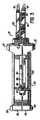
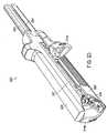
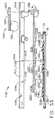
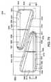
図1及び図2を参照して、リニア吻合ステープリング器具(概して20)は、上側の細長いアンビル携行顎部材22及び下側の細長いステープルカートリッジ携行顎部材24を含む。上側アンビル携行顎部材22は、そこから前方へと延びる顎部材の前側部分を備えるハンドル26によって支持され得る。下側ステープルカートリッジ携行顎部材24は、そこから前方へと延びる顎部材の前側部分を備えるハンドル28によって支持され得る。図3で示されているように、上側ハンドル26及び下側ハンドル28は、ハンドグリップを成形するよう好適に成形され、外科医によるステープル器具の取り扱い及び操作を容易にすることができる。拡大した前方突出部27及び小さな後方突出部29は、この目的のためにそれぞれのハンドル上に設けられていてもよい。様々な実施形態では、ハンドル26及び28は、例えば他の軽量材料で作製できるのに対して、顎部材22及び24は、例えばステンレス鋼又は他の同様な材料で作製され得る。 1 and 2, a linear anastomosis stapling instrument (generally 20) includes an upper elongate anvil carrying
図5に示すように、上側顎部材22は、上部壁31によって接続された一対の対向する細長い側壁30を含む、単一片の細長いチャネル形フレームを含んでもよい。上側ハンドル26は、上側ハンドル内部でその前方端部に隣接して配置された一対の懸垂耳部32を含んでもよい。上側顎部材22は、その上部壁31に沿って中間位置で成形されたスロット34(図4)を含むことができ、これを通じて懸垂耳部32は下向きに突出することができる。ラッチピン36は、上側顎部材22の側壁30に成形された円形孔を通じて、及び懸垂耳部32に成形された円形孔を通じて延在し、上側顎部材を上側ハンドル26に旋回可能に接続することができる。 As shown in FIG. 5, the
図5を参照して、上側顎部材22の前方部分は、一対の細長い内側に延びるフランジ38が設けられており、これはステープル器具のアンビル40を画定することができる。フランジ38は、アンビル40の全長に沿って延在する、中央の長手方向スロット42によって分離される。中央スロット42の近位端において、フランジ38は内側に傾斜しているガイド面41が設けられていてもよい。フランジ38にはそれぞれ、均一に離間されたステープル成形ポケット44の2つの長手方向列が設けられていてもよい。図4及び図5を参照して、先細のアンビル先端部46は、アンビル携行顎部材22の前方で実装されて、中空管状の身体の内蔵内への顎部材の挿入を容易にすることができる。アンビル先端部46は細長い本体48(図4)を含むことができ、これは上側顎部材の側壁30及びフランジ38によって画定された、アンビル40の上の長手方向通路を通じて挿入することができる。この細長い本体48は、ラッチピン36の上で懸垂耳部32の間で延在することができ、並びに耳部32の後ろに配置された、拡大された後部分50を含んで、アンビル先端部46を定位置に上側顎部材22上に保持することができる。 Referring to FIG. 5, the front portion of the
図2及び図6を参照して、下側カートリッジ携行顎部材24は、底壁53によって接続された一対の対向する細長い側壁52を含む、単一片の細長いチャネル形フレームを含んでもよい。下側顎部材24の後方部分に沿って、一対の離間した、細長い直立したサイドフランジ54(図2)は、その対向する側壁52から上方に延びてもよい。図5及び図6に示されているように、そのサイドフランジ54の間の下側顎部材24の幅は、その側壁30間の上側顎部材22の幅よりも大きくてもよく、ステープル器具が操作のために組み立てられたときに、上側顎部材の後方部分が下側顎部材のサイドフランジ54の間に受容できるようにする。図2に示されるように、下側顎部材24のそれぞれのサイドフランジ54は、上側顎部材22上のラッチピン36と位置合わせして配置された垂直ノッチ56を含んでもよい。上側顎部材22及び下側顎部材24が組み立てられたとき、ラッチピン36の対向する端部はノッチ56に受容することができる。 With reference to FIGS. 2 and 6, the lower cartridge carrying
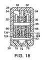
図2及び図6に示されているように、少なくとも2つの横方向に離間した長手方向列内に配列された複数の外科用ステープル61(図17)を受容するように適合されているステープルカートリッジ60を、下側顎部材24は支持することができる。ステープルカートリッジ60は、下側顎部材24の前側部分において、その側壁52の間で実装され得る。ステープルカートリッジ60は、カートリッジの近位端からその遠位端まで延在する中央の細長いスロット62(図6)によって長手方向に分割されてもよい。様々な実施形態において、ステープルカートリッジ60に成形された複数のステープル開口部64は、一対の横方向に離間された列内に配列されてもよく、列の各対は、中央の長手方向スロット62の対向する側上に配置される。複数の外科用ステープル61(図17)はカートリッジ60開口部64内に実装することができる。図6に示されるように、隣接する列内のステープル開口部64は、器具が作動するときに、組織のより有効なステープル留めをもたらすように、互い違いであってもよい。図15及び図16を参照すると、ステープルカートリッジ60は、細長い中央スロット62の対向する側上に位置し、かつ、中央スロットの各側上で開口部64の互い違いの列との間に配置された、一対の長手方向スロット66を含んでもよい。それぞれの長手方向スロット66は、カートリッジ60の近位端からその遠位端に向かって延在することができる。 Staple cartridge adapted to receive a plurality of surgical staples 61 (FIG. 17) arranged in at least two laterally spaced longitudinal rows, as shown in FIGS. 60, the
図17に示されているように、複数のステープルドライバ65は、ステープルカートリッジ60内に装填されるステープル61を作動させるために、ステープル開口部64内に摺動可能に実装することができる。図6を参照して、それぞれのステープルドライバ65は、ステープルカートリッジ60内に提供された隣接する列内に位置する2つのステープル61を同時に作動させるように設計されてもよい。したがって、様々な実施形態では、第1の組のステープルドライバ65は、中央の長手方向スロット62の一方の側上に位置する互い違いの列内のステープル61を作動させるために提供されてもよく、第2の組のステープルドライバ65は、中央の長手方向スロット62の他方の側上に位置する一対の隣接する列内のステープル61を作動させるために提供されてもよい。 As shown in FIG. 17, a plurality of
図2及び図3に示されているように、上記と同様にステープルカートリッジ60の前方端又は遠位端は、先細先端部68を含んで、中空管状の身体の内蔵内への下側顎部材24の挿入を容易にすることができる。その先細先端部68の直ぐ後ろで、ステープルカートリッジ60は、下側顎部材24の側壁52に備えられている、対応するノッチ内に受容することができる一対の後方に延在する突出部70(図14に示されている)が設けられていてもよい。ステープルカートリッジ60の後部において、一対の懸垂アーム72がカートリッジから下方に延在することができる。アーム72はそれぞれ、刻み目が付けられてサイド開口部74を提供することができる。カートリッジ60が下側顎部材24上に組み立てられたとき、その突出部70は、側壁52の前方端部において設けられている対応するノッチに受容することができ、その懸垂アーム72は、顎部材24の底壁53に成形された開口部76(図4)を通じて下方に延在する。下側顎部材24は、開口部76の反対の側上で、その側壁52から下方に延在する、一対の懸垂耳部78(図18)を含んでもよい。旋回ピン80は、下側顎部材24の懸垂耳部78に成形された孔を通じて、かつステープルカートリッジ60上の懸垂アーム72のサイド開口部74を通じて延在し、ステープルカートリッジを下側顎部材に締結することができる。 As shown in FIGS. 2 and 3, the front or distal end of the
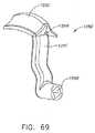
図2を参照して、ステープル器具20は、上側顎部材22及び下側顎部材24を一緒に、顎部材に沿った中間位置において係止するためのラッチ機構(概して90)を含んでもよい。様々な実施形態では、顎部材22及び24は、アンビル40及びステープルカートリッジ60の近位端に隣接した位置において、一緒に係止されてもよい。少なくとも1つの実施形態において、ラッチ機構90は、旋回ピン80(図4)を介して、下側顎部材24に旋回可能に接続されたラッチアーム92(図2)を含んでもよい。ラッチアーム92は構成においてチャネル形であってもよく、並びに下側顎部材24の側壁52をまたぐだけの十分な距離によって離間されている、一対の対向する細長い側壁94(図6)を含んでもよい。ラッチアーム92の各側壁94は、ラッチピン36を受容するために、前方に面するスロット98が設けられている、上方及び前方に延在するフック部材96を含んでもよい。シュラウド100は、ラッチアーム92の下側面上に実装されてもよい。図3に示されるように、ラッチアーム92が閉じているとき、シュラウド100は、下側ハンドル28の底部と位置合わせされて、外科医によるステープル器具20の取り扱い及び操作を容易にすることができる。様々な実施形態では、シュラウド100は、例えばプラスチック又は他の軽量材料で作製することができるのに対して、ラッチアーム92は、例えばステンレス鋼で作製することができる。図7に示されるように、シュラウド100は、その対向する側から外側に延在する細長いフランジ102及び104を含むことができ、これらはラッチアーム92が、その係止位置から非係止位置まで下方に旋回できるようにするフィンガーグリップとして機能することができる。ラッチアーム92が、その閉じた、即ち係止位置まで動くとき、フック部材96のスロット98の表面はラッチピン36と共働することができ、ラッチピン36はラッチアーム92をその係止位置に維持するためのオーバーセンター(over-center)ラッチとして機能することができる。 Referring to FIG. 2, the
図6及び図10を参照して、ステープル器具20の好ましい実施形態は、改善された押し込みバー及びナイフブレードアセンブリ(概して110)を含んでもよく、これは、上側顎部材22及び下側顎部材24それぞれに対する長手方向の運動のために、ステープルカートリッジ60からステープル61を、顎部材間に把持された組織内に駆動するために、ステープル61をアンビル40に対して成形するために、並びに組織に成形されたステープルの列間の線に沿って組織を切開するために摺動可能に実装されてもよい。押し込みバー及びナイフブレードアセンブリ110は、その直立したサイドフランジ54間の下側チャネル形顎部材24内に摺動可能に受容され得る押し込みブロック112(図6)を含むことができる。図11に示されるように、押し込みブロック112は、フランジ116によってアクチュエータノブ114に取り付けることができ、このアクチュエータノブは、その上面に長手方向に延びるノッチ119が設けられている、横方向に突出するフィンガー118を含む。フィンガー118は、押し込みブロック112に成形された横方向のスロット120内にスナップ嵌めされ、長手方向のロック・バー121の下にノッチ119を配置し、押し込みブロック112及びアクチュエータノブ114を一緒に固定することができる。アクチュエータノブ114のフランジ116は、下側顎部材24の1つサイドフランジ54に成形された細長いスロット122(図2)を通じて延在することができ、かつこれに沿って解放される。 With reference to FIGS. 6 and 10, a preferred embodiment of the stapling
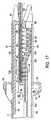
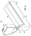
押し込みバー及びナイフブレードアセンブリ110は、押し込みブロック112から前方に突出し、かつステープルカートリッジ60の細長いスロット66(図16)に摺動可能に受容される、一対のステープル押し込みバー124(図10)を含んでもよい。押し込みブロック112は、押し込みバー124が内部に固定されている一対の垂直スロット126(図11)が設けられている。図10に示されているように、それぞれのステープル押し込みバー124の前方端部は、楔形先端部128が設けられていてもよく、これは押し込みバー124がステープルカートリッジ60内に前進すると、ステープルドライバ65を係合するための傾斜したカム表面130を画定する。図21に示されるように、それぞれのステープルドライバ65は、それぞれのステープル押し込みバー124のカム表面130と同じ角度で配向された、傾斜した表面132が設けられて、表面の間に平坦な摺動接触をもたらすことができる。 The pusher bar and
図6及び図10を参照して、押し込みバー及びナイフブレードアセンブリ110は、その直立したサイドフランジ54間で下側顎部材24に沿った長手方向の運動のために摺動可能に実装されているナイフブロック134を含むことができる。ナイフブロック134は、ステープルカートリッジ60の中央の長手方向スロット62内に前方に延在する、ナイフ支持バー136を含んでもよい。面取りされた刃先140が設けられている傾斜したナイフブレード138は、ナイフ支持バー136の前方端部に位置付けることができる。ナイフブレード138の面取りされた刃先は、細長い顎部材22及び24に対してある角度で配向され、ステープルカートリッジ60の中央の長手方向スロット62内に摺動可能に受容することができる。 With reference to FIGS. 6 and 10, the pusher bar and
様々な実施形態では、ナイフブロック134は、内部を通じて延びる一対の長手方向スロット135(図19)を含んでもよく、これはステープル押し込みバー124を摺動可能に受容し、押し込みブロック112がナイフブロックに対して摺動できるようにする。したがって、押し込みブロック112がアクチュエータノブ114によってステープルカートリッジ60に向かって前進したとき、ステープル押し込みバー124はナイフブロック134を通じて摺動することができ、これは押し込みブロックが動いてナイフブロックと係合するまで静止したままである。ナイフブロック134が押し込みブロック112と係合した後、ナイフブロック及び押し込みブロックはステープルカートリッジ60に向かって同時に前進することができる。図17に示されているように、ナイフブレード138は、顎部材間に把持された組織にステープル61を成形し、ステープル列間の組織を切開しながら、ステープル押し込みバー124に沿ってステープルカートリッジ60を通じて前進することができる。その後、アクチュエータノブ114が後退されると、押し込みブロック112は、静止したままであり得るナイフブロック134を通じて、後方にステープル押し込みバー124を最初に摺動することができる。それぞれのステープル押し込みバー124は、オフセット部分142含むことができ、これは、ステープル押し込みバー124が所定の距離だけ引かれた後に、移動してナイフブロック134と係合することができる。ナイフブロック134に係合するステープル押し込みバー124のオフセット部分142を用いて、押し込みブロック112及びナイフブロック134は、アクチュエータノブ114によって同時に後退され、押し込みバー124及びナイフブレード138を開始位置まで戻すことができる。 In various embodiments, the
本発明の様々な実施形態によると、ステープル器具20は、顎部部材にクランプ力を適用し、ステープル61の成形中にステープルカートリッジ60及びアンビル40を一緒に付勢するための、顎部クランプ手段が設けられていてもよい。顎部クランプ手段は、ラッチ機構から離れた位置において、顎部材を付勢して離して、ステープル61が成形されたときに、ステープルカートリッジ60及びアンビル40上にかけられた力に抵抗するための手段を含んでもよい。少なくとも1つの実施形態では、カム手段は、顎部材のうちの1つの上に実装されてもよく、ステープルカートリッジ60及びアンビル40を一緒に付勢するために、離れた位置で前述の顎部材を離して移動させるために、他の顎部材と係合可能であってもよい。様々な実施形態では、カム部材は、ラッチ機構から離れて位置において、顎部材のうちの1つの上に旋回可能に実装されてもよい。カム部材は、顎部材の離れた端部を動かすために、第1の動作不能な位置から第2の動作位置まで旋回可能であってもよい。カム部材は、押し込みブロックが前進したときにその動作位置まで移動し、押し込みブロックが後退したときに、押し込みバーの押し込みブロック112及びナイフブレードアセンブリ110がその動作不能な位置に戻ることによって、操作可能になってもよい。 According to various embodiments of the present invention, the stapling
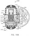
様々な実施形態では、カム機構(概して150)は、図4に示されるように、下側顎部材24の後方端部に隣接して配置されてもよい。カム機構150は、下側顎部材24の直立したサイドフランジ54間に延在する横断旋回ピン154上に旋回可能に実装されたカム部材152を含んでもよい。カム部材152は、上側顎部材22の上部壁31をカム152とその第1の動作不能な位置(図12)において係合するための第1の下方カム表面156と、上側顎部材22の上部壁31を、配置されているカム152とその第2の動作位置(図13)において係合するための第2の上方カム表面158とを含んでもよい。第1のカム表面156は、上側及び下側顎部材を、その動作不能な位置においてカム152と実質的に平行に維持するように配置されてもよい。第2のカム表面158は例えば、カム152がその動作不能な位置からその動作位置まで旋回するときに、約3.2mm(0.125インチ)だけ、上側顎部材22の下方端部を上昇させるように配置されてもよい。更に、上側顎部材22は、カム部材152がその動作不能な位置からその動作位置まで移動されたときに、上側顎部材22の後方部分が、下側顎部材24から離れて上方に曲がることができるように十分に可撓性であってもよい。 In various embodiments, the cam mechanism (generally 150) may be positioned adjacent to the rear end of the
図4に示されているように、カム部材152は、放射状に延びているノッチ160を含んでもよく、これはカムを大きな前方フィンガー162及び小さな後方フィンガー164に分離させる。前方カムフィンガー162は、平坦で後方に面している表面165を含んでもよく、後方カムフィンガー164は、傾斜した前方に面している表面166を含んでもよい。カム152がその動作不能な位置にある状態で、前方カムフィンガー162及び後方カムフィンガー164は、下側顎部材24の底壁53に成形された細長いスロット168を通じて下方に延在することができる。 As shown in FIG. 4, the
様々な実施形態では、カム部材152は、押し込みブロックが前進したときに、押し込みブロク112がその動作不能な位置からその動作位置まで移動することによって、操作可能になってもよい。図11に示されるように、押し込みブロック112は、一対の後方に延在するアーム170を含んでもよく、これらは離間されて、それらの間の間隙172を画定する。アーム170の後方端部170は、間隙172にわたって延びるカムアクチュエータピン174によって接続されてもよい。図4及び図11を参照して、カム部材152がその動作不能な位置に配置されている状態で、前方カムフィンガー162は、押し込みブロック112のアーム170間で間隙172を通じて延びることができる一方で、カムアクチュエータピン174はカム部材の前方フィンガー162と後方フィンガー164との間のノッチ160内に受容され得る。 In various embodiments, the
図12に示されているように、カム部材152がその第1の動作不能な位置に配置されている状態で、上側顎部材22の上部壁31は、カム部材の第1のカム表面156の上にかかっていてもよい。カム部材152がその動作不能な位置にある状態で、上側顎部材22の上部壁31は、下側顎部材24の底壁53に実質的に平行であってもよい。更に、押し込みブロック112は、ナイフブロック134から後方に離間されたその開始位置に配置されてもよい。矢印182(図13)によって示されているように、押し込みブロック112が前進したとき、カムアクチュエータピン174は、前方カムフィンガー162の後方表面165に係合して、矢印184によって示されているように、カム部材152を反時計周りの方向に回転させて、カム部材をその第2の動作位置まで旋回させ、その第2のカム表面158を、上側顎部材22の上部壁31と係合させることができる。カム部材152がその動作位置まで旋回されている状態で、上側顎部材22の上部壁31は、矢印186によって示されているように、下側顎部材24の底壁53から外へ上方に曲げられ得る。カム部材は、上側顎部材22及び下側顎部材24に力を適用することができ、これらは顎部材の後方部分を曲げて離す。上側顎部材22及び下側顎部材24の後方部分を曲げて離すによる結果として、上側顎部材22及び下側顎部材24の前側部分に更なるクランプ力が適用され、顎部材間で把持されている組織に対してアンビル40及びステープルカートリッジ60をクランプすることができる。したがって、アンビル40及びステープルカートリッジ60は、押し込みバー及びナイフブレードアセンブリ110が前進されてステープル61を成形し、組織を切開したときに、アンビル及びステープルカートリッジ上にかけられる力に対して抵抗するよう、一緒に付勢されてもよい。 As shown in FIG. 12, with the
図13を参照して、ステープル61が成形された後に、押し込みブロック112が後退されたとき、カムアクチュエータピン174は、後方カムフィンガー164の傾斜表面166を係合して、時計方向にカム部材152を旋回することができる。カムアクチュエータピン174が傾斜表面166に沿ってノッチ160内に移動すると、カム部材152は、時計方向に旋回し、その第1のカム表面156が、上側顎部材22の上部壁31と係合した状態で、その第1の動作不能な位置(図12)に戻ることができる。結果として、カム152によって上側顎部材22及び下側顎部材24の後側部分上にかけられた力は解放され、上側顎部材22の上部壁31は、下側顎部材24の底壁53と実質的に平行な関係に戻ることができる。同様に、顎部材22及び24の前方部分に適用されたクランプ力は解放されて、アンビル40及びステープルカートリッジ60を外すことができる。 Referring to FIG. 13, when the pusher block 112 is retracted after the staple 61 is formed, the cam actuator pin 174 engages the inclined surface 166 of the rear cam finger 164 to cause the
様々な実施形態において、ステープル器具20は、ステープル器具のステープルカートリッジ60とアンビル40との間の所定の間隙を維持するために、顎部材のうちの1つ上に実装されるスペーサー手段を含んでもよい。図4及び6を参照して、このスペーサー手段は、ステープルカートリッジ60の遠位端に隣接して実装されたスペーサーピン190として具体化されてもよい。スペーサーピン190は、ステープルカートリッジ60を通じて、下側顎部材24の底壁53から垂直に上方に延在し、所定の距離だけ、ステープルカートリッジの上部から上方に延びることができる。図5に示されるように、アンビル40の1つのフランジ38は、スペーサーピン190を係合するために、その遠位端に隣接するフランジ区分192を含んでもよい。ステープル器具が操作のために組み立てられた状態で(図4)、スペーサーピン190は、アンビル40とステープルカートリッジ60との間の所定の間隙を維持するために、フランジ区分192を係合することができる。 In various embodiments, the stapling
ステープル器具20の操作において、ステープル留めされ、切開されるべき組織は、顎部材22と24との間に初めに配置され、顎部材によってクランプされ得る。このように、ハンドル26及び28は、ラッチアーム92の旋回運動によって、そのラッチ解除位置(図2)まで係合解除され得る。結果として、ラッチピン36の対向する端部は、ラッチアーム92のフック部材96に成形されたスロット98から係合解除されてもよい。その後、上側顎部材22及び下側顎部材24は、下側顎部材のサイドフランジ54に成形されたスロット56から、ラッチピン36を係合解除することによって分離されてもよい。 In operation of the stapling
次いで、ステープル留めされ、切開されるべき組織は、顎部材22及び24の上に配置することができる。例えば、図17に示されているように、一片の管状腸組織は、それぞれの顎部材の前方部分上に滑り込ませることができる。組織が顎部材上に配置された後、ステープル器具20は再度組み立てられてもよい。再組み立ては、ラッチピン36と下側顎部材24の直立サイドフランジ54に成形されている垂直スロット56とを位置合わせすることによって達成することができる。その後、下側顎部材24のサイドフランジ54は、上側顎部材22の側壁30をまたぎながら、上側ハンドル26内部に配置できる一方で、ラッチピン36の対向する端部は、垂直スロット56内に挿入されてもよい。最後にラッチアーム92は、そのラッチ位置(図3)まで、そのカバー100が、下側ハンドル28の底部とぴったり重なった状態で、上方に旋回することができる。結果として、フック部材92は、ラッチピン36の上で旋回することができ、スロット98は、ラッチピンの対向する端部を受容することができる。したがって、上側顎部材22及び下側顎部材24は、アンビル40及びステープルカートリッジ60に隣接して、それらに沿った中間位置において一緒に掛け金をかけることができる。更に、スペーサーピン190は、アンビル40とステープルカートリッジ60との間の所定の間隙を維持するために、身体の組織を通じてアンビル40のフランジ区分192を係合することができる。 The tissue to be stapled and dissected can then be placed over the
組織が顎部材間でクランプされた後、押し込みバー及びナイフブレードアセンブリ110を作動させるために、ステープル器具20は作動ノブ114を前進させることによって発射することができる。最初に、カム機構150の作動において、押し込みブロック112及び押し込みバー124(図4)は、ナイフブロック134が静止した状態で留まることができるまま、前進させることができる。カム部材152を作動させるために、押し込みブロック112及びその押し込みバー124だけが前進されるため、ステープル器具20を操作するのに必要とされる初期力は最小限にすることができる。 After the tissue is clamped between the jaw members, the stapling
図12を参照して、押し込みブロック112が最初に前進している間に、押し込みバー124は、ナイフブロック134を通じて摺動することができ、押し込みバーの楔形先端部128は、ステープルカートリッジ60のスロット66を通って前進し始めることができる。押し込みブロック112がナイフブロック134に向かって前進すると、そのカムアクチュエータピン174は、前方カムフィンガー162の後方表面165に係合して、図13の矢印184によって示されているように、カム152を反時計周りの方向に旋回し、カム部材の第2のカム表面158を上側顎部材22の上部壁31と係合させることができる。カム部材152は、上側顎部材22及び下側顎部材24に力を適用することができ、これらは顎部材の後側部分を曲げて離す。結果として、上側顎部材22の上部壁31の後方端部は、下側顎部材24の底壁53の後方端部に対して、例えば約3.2mm(0.125インチ)だけ上方に曲げられ得る。顎部材22及び24の後方端部を曲げて離すことによって、顎部材の前側部分上への更なるクランプ力となり、顎部材間では把持されている組織に対してアンビル40及びステープルカートリッジ60をクランプすることになる。これらの更なるクランプ力は、アンビル40及びステープルカートリッジ60上にかけられた力に対して耐える傾向がある一方で、組織は切開され、ステープル61はアンビル40に対して成形され、アンビル40とステープルカートリッジ60との間に望ましい空間を維持して、高さが実質的に均一である成形されたステープル61を作る。 Referring to FIG. 12, while the push block 112 is initially advanced, the
図13を参照して、カム機構150が作動された後、押し込みブロック112は、その後、ナイフブロック134に実質的に係合してステープルカートリッジ60に向かってナイフブロック134の長手方向の運動を開始する。様々な実施形態において、押し込みブロック112とナイフブロック134との間の初期の空間は、カム部材152がその動作位置に到達する直前に、押し込みブロック112がナイフブロック134に係合するように配置されてもよい。あるいは、押し込みブロック112とナイフブロック134との間の初期の空間は、カム部材152のその動作位置への運動が完了した後、押し込みブロック112がナイフブロック134を最初に係合するように配置されてもよい。押し込みブロック112がナイフブロック134に係合するとき、アンビル40及びステープルカートリッジ60それぞれの中央の長手方向スロット42及び62に沿ったナイフブレード138の前進を開始することができる。したがって、ステープル押し込みバー124及びナイフブレード138は、同時に前進して、アンビル40とステープルカートリッジ60との間に把持された組織を切開することができる。 Referring to FIG. 13, after the cam mechanism 150 is activated, the pusher block 112 then substantially engages the
押し込みブロック112が前進するとき、ステープル押し込みバー124は、ステープルカートリッジ60に設けられたスロット66に沿って長手方向に動かすことができる。ステープル押し込みバー124の2つの楔様カム表面130は、スロット66を通じて動き、ステープルドライバ65の傾斜表面と係合し、その後、カートリッジ60からステープル61を駆動し、ステープル61をアンビルフランジ38に対してB形の構成に成形することができる。カム表面130は、押し込みブロック112から同じ距離に配置されて、中央の長手方向スロット62の対向する側面上に配置されたステープルドライバ65を同時に作動させることができる。同時に、ナイフブロック134は前進して、アンビル40の中央の長手方向スロット42を通じて、及びステープルカートリッジ60の中央の長手方向スロット62を通じてナイフブレード138を動かし、顎部材間に把持された組織を切開することができる。カム機構150を介して上側顎部材22及び下側顎部材24の前側部分に適用された追加のクランピング力は、ステープル61が成形されるときにアンビル40及びステープルカートリッジ60にかけられる力に耐える傾向があり得る。 As the push block 112 advances, the
押し込みブロック112が十分に前進して、カートリッジ60内のステープルの全てを成形した後、押し込みブロックは、アクチュエータノブ114の後退によって、その開始位置にむかって後退することができる。最初に、押し込みブロック112のみが、ステープルカートリッジ60から後方に動くことができ、なぜならばステープル押し込みバー124が、動かないままのナイフブロック134を通じて摺動するからである。ステープル押し込みバー124のオフセット部分142がナイフブロック134の前方部と係合するとき、ナイフブロックは、押し込みブロック112に沿ってステープルカートリッジ60から後方に動くことができる。結果として、ステープル押し込みバー124及びナイフブレード138はステープルカートリッジ60及びアンビル40から同時に後退することができる。 After the push block 112 is fully advanced to form all of the staples in the
押し込みブロック112がその開始位置に向かって戻るとき、カムアクチュエータピン174は、後方カムフィンガー164の傾斜表面166を係合して、カム部材152をその動作不能な位置に向かって時計方向に旋回することができる。カムアクチュエータピン174は、傾斜表面166に沿って、カムフィンガー162と164との間のスロット160内へ移動して、カム部材152をその動作不能な位置まで戻すことができる。結果として、カム部材152の第2のカム表面158は、上側顎部材22の上部壁及び上側顎部材22の上部壁31の後方端部から係合解除されて、下方に移動し第1のカム表面156と係合することができる。同時に、前方カムフィンガー162は、押し込みブロック112上のフィンガー170間の間隙172内へと下方に旋回して、カムフィンガー162及び164の両方は、下側顎部材24の底壁53に成形されたスロット168内へと下方に旋回することができる。その後、カム部材152がその動作不能な位置にある状態で、ラッチングアーム92は、図2に示されるように下方に旋回し、上側顎部材22及び下側顎部材24が外れるようにする。この時点で、切開され、ステープル留めされた組織は顎部材から取り外すことができる。 As the push block 112 returns toward its starting position, the cam actuator pin 174 engages the inclined surface 166 of the rear cam finger 164 and pivots the
上記で要約されているように、外科用ステープル器具は、例えば、アクチュエータノブ114(図1)などのアクチュエータノブを含んでもよく、これは押し込みバーアセンブリ110(図10)などの押し込みバーアセンブリを外科用ステープル器具のステープルカートリッジ内に前進させるように構成されてもよい。様々な実施形態では、アクチュエータノブ114は、外科医が力をアクチュエータノブ114に適用することができるように、外科医によって把持されるように構成され得る。様々な状況において、アクチュエータノブ114は、それが遠位に前進した時に、手術部位を包囲する組織と接触する、即ちこれと当接する場合がある。少なくとも1つの状況において、結果として、外科医はアクチュエータノブ114が組織を通過できるように、ステープル器具を再配置する必要がある場合がある。他の状況において、外科医は組織によってアクチュエータノブ114を押し必要がある場合がある。いずれかの事象において、そのような状況は不適切であり得、結果として、アクチュエータノブが周囲組織に衝突する恐れがあるアクチュエータノブの可能性を低減するために操作することができるアクチュエータノブを有するステープル器具に対する必要性が存在する。 As summarized above, a surgical stapling instrument may include an actuator knob, such as, for example, actuator knob 114 (FIG. 1), which drives a push bar assembly such as push bar assembly 110 (FIG. 10). It may be configured to be advanced into the staple cartridge of the stapling instrument. In various embodiments, the
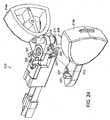
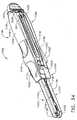
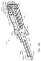
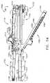
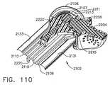
本発明の様々な実施形態では、図21を参照して、ステープル器具220は、上側ハンドル226から延在するアンビル携行顎部材222、下側ハンドル228から延在するステープルカートリッジ携行顎部材224、並びにアクチュエータノブ214a及び214bを含んでもよく、アクチュエータノブ214a及び214bは、例えば図24に示されているように押し込みバーアセンブリ210などの押し込みバーアセンブリと操作可能に係合することができる。様々な実施形態では、ステープルカートリッジは、例えばステープルカートリッジが消耗された後、それが他のステープルカートリッジと交換できるように、ステープルカートリッジ携行顎部材224に取り外し可能に取り付けられてもよい。少なくとも1つの実施形態では、押し込みバーアセンブリ210は、一体成型された、又はそれに操作可能に実装されたステープルドライバを含んでもよく、これは上記で要約したように、ステープルカートリッジを通じて動くことができる。少なくとも1つの他の実施形態では、ステープルカートリッジは、内部に含まれるステープルドライバを含んでもよく、これは、押し込みバーアセンブリによって、係合することができ、かつ遠位に押すことができる。いずれかの事象において、第1のアクチュエータノブ214aは、それが例えば、押し込みバーアセンブリ210から操作可能に係合解除する第1の位置(図21)と、それが押し込みバーアセンブリ210と操作可能に係合する第2の位置(図22)との間で回転することができる。同様に、第2のアクチュエータノブ214bは、それが押し込みバーアセンブリ210とそれぞれ操作可能に非係合及び係合である第1の位置と第2の位置との間で回転されるように構成され得る。 In various embodiments of the present invention, referring to FIG. 21, a
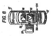
様々な実施形態では、上記の結果として、ステープル器具のアクチュエータノブは、アクチュエータノブが、それが前進されたときに、手術部位を包囲する組織と接触する、即ち当接し得る場合には、アクチュエータノブはその後退した位置にとどまることができる一方で、他のアクチュエータノブは延出して押し込みバーアセンブリを遠位に前進させることができるように、選択的に押し込みバーアセンブリと係合することができる。少なくとも1つのかかる実施形態では、図22を参照して、第1のアクチュエータノブ214aは、押し込みバーアセンブリ210と操作可能に係合できる一方で、第2のアクチュエータノブ214bはその後退位置に留まることができるように、その第2の位置内に回転することができる。したがって、図23を参照して、第1のアクチュエータノブ214aは、押し込みアセンブリ210を動かすために、外科用ステープラー220の第1の側201に沿って上側ハンドル226及び下側ハンドル228に対して遠位に前進することができる。少なくとも1つの実施形態では、第1のアクチュエータノブ214aは、上側ハンドル226と下側ハンドル228との間に画定された、又はこれらの内部の第1のスロット227内で摺動することができる。様々な他の状況において、図28を参照して、第1のアクチュエータノブ214aは、その後退した位置に留まることができる一方で、第2のアクチュエータノブ214bはその広がった位置内に回転することができる。上記と同様に、第2のアクチュエータノブ214bは、ステープル器具210の第2の側203に沿って遠位に前進され、例えば、第2のスロット229内の押し込みバーアセンブリ210に前進することができる。少なくとも1つの実施形態では、両方のアクチュエータノブ214は広げられ、押し込みバーアセンブリ210を遠位に前進させることができる。様々な代替の実施形態では、図示されていないが、ステープル器具は、押し込みバー及び/又はナイフブレードアセンブリを動かすように選択的に使用され得る、2つを超えるアクチュエータノブを含んでもよい。実際には、上記の結果として、外科用器具のアクチュエータノブは、互いに独立して、押し込みバーアセンブリとすることができる。 In various embodiments, as a result of the above, the actuator knob of the stapling instrument may be used when the actuator knob contacts or abuts the tissue surrounding the surgical site when it is advanced. Can remain in its retracted position, while other actuator knobs can selectively engage the push bar assembly so that it can extend to advance the push bar assembly distally. In at least one such embodiment, referring to FIG. 22, the
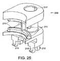
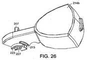
様々な実施形態では、上記に加えて、ステープル器具のアクチュエータノブは、それらが定位置に保持され、押し込みバーアセンブリと操作可能な係合から外れて保持され得る第1の位置に置くことができる。少なくとも1つの実施形態では、図24を参照して、ステープル器具201は、アクチュエータノブ214を、それらがそれらの第1の位置と第2の位置との間で回転されるときにガイドするように構成され得るガイド部材209を更に含んでもよい。様々な実施形態では、図24〜26を参照して、ガイド部材209は、アクチュエータの部214が回転された時に、ガイド部材209が、それに沿ってアクチュエータノブ214が動く経路を決定することができるように、アクチュエータノブ214の溝部213内に摺動可能に受容され得るガイドレール211を含んでもよい。更に、ガイドレール211及び溝部213は、アクチュエータノブ214が不用意に、例えば近位に及び/又は遠位に動くのを協働して防ぐことができるインターロック機構を含んでもよい。少なくとも1つのかかる実施形態では、ガイド部材209は、押し込みバーアセンブリ210が上記のように遠位に前進されたときに、押し込みバーアセンブリ210に沿って1つ以上のアクチュエータノブ214が平行移動するのを防ぐことができる。様々な実施形態では、アクチュエータノブ214が、それらの広がった位置へと不用意に回転され得る可能性を低減できるように、わずかな摩擦若しくは干渉がガイドレール211と溝部213との間に存在してもよい。図示されていないが、アクチュエータノブは、そこから延びるガイドレールを含んでもよく、これは例えばガイド部材内の溝部に摺動可能に受容されてもよい。いずれかの事象において、図25を参照して、ガイド部材209は、1つ又は2つ以上の保持部材215を含んでもよく、これらは、上側ハンドル226及び下側ハンドル228の中間の位置において、ガイド部材209を定位置に保持するように構成され得る。更に、図24及び図25を参照して、ガイド部材209は、開口部217を含んでもよく、これは内部を通じて延びる保持ピン219を受容するよう構成されてもよく、ここでは保持ピン219は、上側ハンドル226及び/又は下側ハンドル228と係合してガイド部材209を定位置に保持するように構成され得る。 In various embodiments, in addition to the above, the actuator knobs of the stapling instrument can be placed in a first position where they can be held in place and held out of operable engagement with the pusher bar assembly. . In at least one embodiment, referring to FIG. 24, stapling
様々な実施形態では、アクチュエータノブ214が、上記のようにそれらの第1の位置と第2の位置との間で回転されると、溝部213は回転されてガイドレール211との係合が外れ、アクチュエータノブ214は、押し込みバーアセンブリ210と操作可能に係合することができる。少なくとも1つの実施形態では、主に図24を参照して、押し込みバーアセンブリ210は、第1のクラッチ機構、例えばスロット又は溝部205などを含んでもよく、アクチュエータノブ214はそれぞれ、第2のクラッチ機構、例えば突出部207などを含んでもよく、ここで、1つ又は2つ以上のアクチュエータノブ214を押し込みバーアセンブリ210と操作可能に係合するために、第1のクラッチ機構及び第2のクラッチ機構は互いに操作可能に係合されてもよい。少なくとも1つのかかる実施形態では、1つ又は2つ以上のアクチュエータノブ214に力が適用されたとき、この力が突出部207及びスロット205の側壁を通じて押し込みバーアセンブリ210に伝播され得るように、突出部207はスロット205内に密接して受容されてもよい。少なくとも1つの実施形態では、上記と同様に、わずかな摩擦又は締り嵌めが、突出部207とスロット205との間に存在し、アクチュエータ214をそれらの広がった位置に保持することができる。いずれかの場合において、図示されていないが、第1のクラッチ機構は、アクチュエータノブ内の凹部又はスロット内に受容されるように構成され得る押し込みバーアセンブリから延びる突出部を含んでもよい。上記に加えて、又は上記の代わりに、図24を参照して、押し込みバーアセンブリ210は、アクチュエータノブ214内のスロット又は溝部223内に摺動可能に受容されるように構成され得る第2のガイドレール221を更に含んでもよく、ここではレール221及び溝部223は、アクチュエータノブ214をそれらの第2の位置内に案内するか、及び/又は、アクチュエータノブ214がそれらの第2の位置にある時点で、アクチュエータノブ214からの力を押し込みバーアセンブリ210に伝播するように構成されてもよい。ガイドレール211と同様に、ガイドレール221は、溝部223とのわずかな摩擦又は締り嵌めを生じさせてアクチュエータノブ214を定位置に保持するように構成されてもよい。上記に加えて、様々な実施形態では、アクチュエータバー210は、その周囲でアクチュエータノブ214が回転することができる支柱225を含んでもよい。少なくとも1つの実施形態では、アクチュエータノブ214は、凹部227を含んでもよく、これは、凹部227の側壁が支柱225の周囲で密接して受容し、摺動することができ、結果として、支柱225は、アクチュエータノブ214をそれらが例えば第1の位置と第2の位置との間で回転されるときに案内することができるように凹凸があるようにされてもよい。 In various embodiments, when the actuator knobs 214 are rotated between their first and second positions as described above, the
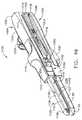
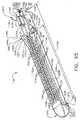
本発明の様々な実施形態では、ステープル器具は、ステープル器具の第1の側及びステープル器具の第2の側に沿って選択的に前進されるように構成され得る、アクチュエータノブを含んでもよい。少なくとも1つの実施形態では、図29及び30を参照して、ステープル器具320は、上側ハンドル326、下側ハンドル328、及びアクチュエータノブ314を含んでもよく、ここでは、アクチュエータノブ314は上記と同様に、ステープルカートリッジ内に押し込みバーアセンブリを前進させるように構成されてもよい。少なくとも1つの実施形態では、上側ハンドル326及び下側ハンドル328は、それらの間に第1のスロット327及び第2のスロット329を画定することができ、ここではスロット327及び329は両方ともアクチュエータノブ314が内部を通じて摺動できるように構成されてもよい。より詳細には、様々な実施形態では、アクチュエータノブ314は、それが第2の側301に沿って第1のスロット327を通じて、あるいは第2の側303に沿って第2のスロット329を通じて選択的に摺動できるように構成されてもよい。様々な実施形態では、図31を参照して、ステープル器具320は、第3のスロット331を更に含んでもよく、これはアクチュエータノブ314が、ステープル器具の1つの側から他方に移動できるように構成されてもよい。このような実施形態の少なくとも1つでは、外科医は、アクチュエータノブ314がステープル器具の1つの側に遠位に前進されたときに組織に衝突する場合があるように見える場合は、アクチュエータノブ314はそれが前進する前にステープル器具の他の側上に回転することができるように、アクチュエータノブ314を選択的に配置することができる。例示されている実施形態の第1及び第2の側は、外科用器具320の反対の側上に位置しているが、例えば第1及び第2のスロットが隣接する側上、及び/又は互いに正反対ではない側上に位置するような他の実施形態も考えられる。更に、丸みを帯びた、及び/又は円弧状の部分を有する器具のように、ステープル器具の側面同士が容易に区別できないような他の実施形態も考えられる。 In various embodiments of the present invention, the stapling instrument may include an actuator knob that may be configured to be selectively advanced along the first side of the stapling instrument and the second side of the stapling instrument. In at least one embodiment, referring to FIGS. 29 and 30, the
様々な実施形態では、図29を参照して、第1のスロット327はそれが、第2のスロット329によって画定される経路に平行であるか、又は少なくともこれと実質的に平行であるアクチュエータノブ314のための経路を画定するように構成されてもよい。少なくとも1つの実施形態では、第3のスロット331はそれが、スロット327及び329によって画定される経路に垂直であるか、又は少なくともこれと実質的に垂直であるアクチュエータノブ314のための経路を画定するように、第1のスロット327及び第2のスロット329を接続するように構成されてもよい。かかる実施形態では、アクチュエータノブ314は、外科用器具の上部の上で回転されて、アクチュエータノブ314を第1の側301から第2の側303まで移動させることができる。外科医が、第1の側301上にアクチュエータノブ114を再配置することを決定した場合には、外科医はアクチュエータノブ314を、それが第1のスロット327内にもう一度位置するまでスロット311を通じて後方に戻すことができる。様々な他の実施形態では、図示されていないが、第3のスロットは、スロット327及び329によって画定される経路と平行であり、又は少なくともこれと平行であるか、及び/又はこれと同一平面にあるか、又はこれと少なくとも実質的に同一平面にあるアクチュエータノブ314のための経路を画定することができる。更に様々な実施形態では、第3のスロットは、スロット327及び329によって画定される経路に対して歪曲している経路を画定することができる。いずれかの事象において、第3のスロットは、作動装置ノブがその内部に摺動することができるように、第1及び第2スロットを接続するように構成されてもよい。 In various embodiments, referring to FIG. 29, the
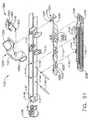
上記のように、ステープル器具320は、アクチュエータノブ314と操作可能に係合することができる、押し込みバーアセンブリを含んでもよく、これによってアクチュエータノブ314は、押し込みバーアセンブリを遠位に前進させるように構成され得る。様々な実施形態では、図33を参照して、ステープル器具320は、ナイフアセンブリと操作可能に係合された第1の部分333、及び、これに加えて第1の部分333に回転可能に実装され得る第2の部分335を含むことができる押し込みバーアセンブリ310を含んでもよい。少なくとも1つの実施形態では、第1の部分333は、それを中心として第2の部分335が回転できる軸337を画定してもよい。少なくとも1つのそのような実施形態では、第2の部分335は、第1の部分333を密接して受容するように構成され得る、内部に画定された開口部339を含んでもよい。少なくとも1つの実施形態では、図示されていないが、押し込みバーアセンブリ310は、例えば第2の部分335を第1の部分333に保持するために、第1の部分333の溝部内に延在するように構成された1つ又は2つ以上の保持部材、例えば止めねじなどを更に含んでもよい。様々な実施形態では、第2の部分335は、そこから延在する取付部341を含んでもよく、これはアクチュエータノブ314を第2の部分335に保持するように構成され得る。アクチュエータノブを、上記のようにステープル器具320の第1の側から他方の側に移動させるために、アクチュエータノブ314及び第2の部分335は、アクチュエータノブ314が第1のスロット327及び第2のスロット329内に選択的に配置され得るように、第1の部分333に対して回転されてもよい。少なくとも1つの実施形態では、図示されていないが、ステープル器具は、それがステープルカートリッジ内に前進された時に、アクチュエータノブを受容するための2つを超えるスロットを有することができる。いずれかの事象において、様々な代替の実施形態では、第1の部分333及び第2の部分335は、それらが軸337を中心として一緒に回転するように、一緒に固定して実装されてもよい。少なくとも1つのそのような実施形態では、第1の部分333は、押し込みバーアセンブリ310の実質的に非回転可能部分に対して回転するように構成されてもよい。 As described above, the stapling
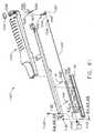
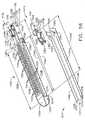
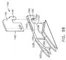
図34を参照すると、概して1100として示される外科用ステープル器具は、第1のハンドル部分1102及び第2のハンドル部分1104を有し得る。様々な実施形態において、第1のハンドル部分1102及び第2のハンドル部分1104は、例えば外科医によって把持されるように構成することができ、ハンドグリップ部分1106を構成し得る。少なくとも1つの実施形態において、図35及び36を参照すると、第1のハンドル部分1102は、第1のフレーム1110に取り付けられた第1のカバー1108を含んでよく、同様に、第2のハンドル部分1104は、第2のフレーム1114に取り付けられた第2のカバー1112を含んでよい。カバー1108及び1112は、人間工学的な外形、又は他の適当な外形に成形されていることにより、外科医が手術部位内でステープル器具1100を操作する助けとなり得る。様々な実施形態において、ハンドルカバー1108及び1112は、例えば、手術部位へのステープル器具1100の挿入を容易とし得る大径突出部1109及び1113をそれぞれ有してもよい。様々な実施形態において、ハンドルカバー1108及び1112は、例えばプラスチック、軽量素材、及び/又は他の任意の適当な材料で成形することができるのに対し、ハンドルフレーム1110及び1114は、例えばステンレス鋼、チタン、及び/又は他の任意の適当な材料で成形することができる。 With reference to FIG. 34, a surgical stapling instrument, shown generally as 1100, can have a
様々な実施形態において、図34〜37を再び参照すると、ハンドル部分1102及び1104の遠位端は、例えば手術部位内の組織を処置するように構成することができるエンドエフェクタ1120を有し得る。少なくとも1つのこのような実施形態では、エンドエフェクタ1120は、下記に更に詳細に述べるようなステープルカートリッジを受容及び/又は保持するように構成されたステープルカートリッジチャネル1122を有し得る。特定の実施形態では、ステープルカートリッジチャネル1122は、第1のハンドル部分のフレーム1110から延びる一体の細長い溝部の形状のフレームを含んでもよい。少なくとも1つの実施形態では、ステープルカートリッジチャネル1122は、底壁1126によって連結された1対の対向した細長い側壁1124を含み得る。ステープルカートリッジチャネル1122の後方、即ち近位の部分に沿って、1対の間隔をおいて直立したサイドフランジ1128が、対向した側壁1124から上方に延び得る。様々な実施形態において、サイドフランジ1128の間のステープルカートリッジチャネル1122の幅は、第2のハンドル部分1104から延びる上側顎部材即ちアンビル1130の幅よりも大きくてよい。少なくとも1つの実施形態では、フランジ1128間の距離は、手術用にステープル器具が組み立てられる際にアンビル1130の少なくとも一部分がサイドフランジ1128間に受容されるように構成することができる。図35に示されるように、各サイドフランジ1128は、下記により詳しく述べるように、アンビル1130から延びる例えば1つ又は2つ以上のラッチ突起部1131、及び/又は第2のハンドル部分1104の他の任意の適当な部分を受容するように構成することができる、例えば切欠き即ち凹部1127を有し得る。 In various embodiments, referring again to FIGS. 34-37, the distal ends of
上記に示したように、再び図34〜37を参照すると、ステープルカートリッジチャネル1122は、1つ又は2つ以上のステープル(図に示されていない)が内部に取り出し可能に格納された、ステープルカートリッジ1150のようなステープルカートリッジを、例えばエンドエフェクタ1120内部に支持及び/又は保持するように構成することができる。様々な実施形態において、図41〜43を参照すると、ステープルカートリッジ1150は、例えば少なくとも2列の横方向に間隔をおいた長手方向の列など、任意の適当な配置でステープルを格納するように構成することができる1つ又は2つ以上のステープル穴1151を有し得る。少なくとも1つの実施形態では、図42及び図43を参照すると、ステープルカートリッジ1150は、ステープルカートリッジ本体1152及びパン、即ち保持具1154を有してよく、ステープルカートリッジ本体1152及び/又はパン1154は、ステープルスレッド及び/又は切開部材を内部に摺動可能に受容するための溝部又は経路を画定するように構成することができる。少なくとも1つの実施形態において、パン1154は例えばスナップ嵌め及び/又は圧入機構によってステープルカートリッジ本体1152と嵌合するように構成することができる可撓性アーム1155を有し得る。図43〜45を参照すると、ステープルカートリッジ1150は、ステープルスレッドアセンブリ1162及び更に切開部材1164を有し得るステープルスレッドアセンブリ1160を更に有してよい。様々な実施形態において、切開部材1164は、例えば刃先1165及びロックアーム1166を有してよく、ロックアーム1166は、切開部材1163がステープルスレッドアセンブリ1162に組み立てられる際にステープルスレッド1162の開口1164内に圧入及び/又はスナップ嵌めされるように構成することができる。他の異なる実施形態では、ステープルスレッドアセンブリ1162は切開部材1164と一体に成形することができる。 As indicated above, referring again to FIGS. 34-37, the
更に上記に加えて、図41〜43を参照すると、ステープルカートリッジ本体1152は、例えば内部に切開部材1164の少なくとも一部分及び/又はステープルスレッドアセンブリ1160及び押し込みバーアセンブリ1200(下記に述べる)の他の任意の部分を受容するように構成することができる、スロット1156のようなスロットを有してよく、スロット1156は、切開部材1164がステープルカートリッジ1150内部で第1の位置と第2の位置との間で動くことができるように構成することができる。様々な実施形態において、スロット1156は、切開部材1164が、例えばステープルカートリッジ1150とアンビル1130との間に位置する組織を切開するために近位位置(図43)と遠位位置との間で動くことができるように構成することができる。再び図43〜45を参照すると、ステープルスレッドアセンブリ1162は、ステープルカートリッジ1150内に配置されたステープルドライバと係合するように構成することができる、カム、ランプ、又はアクチュエータ表面1167を有し得る。様々な実施形態において、図42を参照すると、ステープルカートリッジ1150は、スレッド部分1162によって各ステープル穴1151内において持ち上げられるか又は上方に摺動され得るステープルドライバ1168を有することにより、ステープルドライバ1168の上方への運動によって各ステープル穴1151内に少なくとも部分的に配置されたステープルが射出、又は発射され得る。実際、ステープルドライバ1168は垂直上方に持ち上げることができるが、上方、及びこれに類する語は、例えばステープルドライバ1168が、例えばステープルカートリッジの上面即ちデッキ1158の方向に、及び/又はアンビル1130の方向に動くことを意味し得る。図42に示されるような特定の実施形態では、各ステープルドライバ1168は、カム面1167と同じ角度、及び/又は他の任意の適当な角度を向けられた、1つ又は2つ以上の傾斜面1169を有し得るが、その角度はステープルスレッド1162とステープルドライバ1168との間の比較的平坦な、又は少なくとも実質的に平坦な摺動接触面を与えることができるものである。様々な実施形態において、1個のステープルドライバが1個のみのステープルを発射するように構成することもできるが、特定の実施形態では、1個のステープルドライバが例えば隣り合う列に配置された2個以上のステープルを同時に発射するように構成することもできる。他の装置が、本願にその全容を援用するところの、2008年2月13日出願の発明の名称が「SURGICAL STAPLING INSTRUMENT WITH IMPROVED FIRING TRIGGER ARRANGEMENT」である米国特許出願第12/030,424号に開示されている。 In addition to the above, referring to FIGS. 41-43, the
様々な実施形態において、上記に述べたように、外科用ステープル器具は、組織を切開し、ステープルカートリッジからステープルを発射するように構成された切開部材/ステープルスレッドアセンブリを有し得る。しかしながら特定の実施形態では、外科用ステープル器具は切開部材を必要としないか、又は有さない場合もある。少なくとも1つのこのような実施形態では、組織を切開することなく例えば組織をステープル留めするため、ステープルカートリッジの内部にステープルスレッドが配置されてもよく、及び/又は、外科用器具が、ステープルスレッドをステープルカートリッジ内に動かすように構成されてもよい。特定の他の実施形態では、ステープルカートリッジの内部にステープルスレッドが配置されてもよく、その場合、外科用器具が、ステープルカートリッジ内へと又はステープルカートリッジに対して動かすことができる切開部材を有してもよい。少なくとも1つのこうした実施形態では、切開部材をステープルスレッドと接触するように前進させることによって、切開部材とステープルスレッドとを一緒に前進させることができる。この後、ステープルカートリッジを外科用器具から取り外して、新しいステープルスレッドを有する新しいステープルカートリッジと交換することができるように切開部材を充分に後退させることができる。このような実施形態は、ステープルスレッドが使用の間に摩耗又は変形し得る場合に有用となり得る。ステープルカートリッジの内部に切開部材が配置されてもよく、外科用器具が、ステープルカートリッジ内へと又はステープルカートリッジに対して動くことができるステープルスレッドを有し得る他の実施形態も考えられる。少なくとも1つのこうした実施形態では、上記と同様、切開部材をステープルスレッドと接触するように前進させることによって、切開部材とステープルスレッドとを一緒に前進させることができる。この後、ステープルカートリッジを外科用器具から取り外して、新しい切開部材を有する新しいステープルカートリッジと交換することができるようにステープルスレッドを充分に後退させることができる。このような実施形態は、切開部材が使用の間に摩耗又は変形し得る場合に有用となり得る。様々な実施形態において、下記により詳しく述べるように、ステープルカートリッジは、例えば、外科医又は他の臨床医がステープルカートリッジを扱う際にステープルカートリッジ内部に配置された切開部材に触れることを防止するか、又はその可能性を少なくとも低減するように構成された保護ハウジング又はカバーを有し得る。 In various embodiments, as described above, a surgical stapling instrument can have a cutting member / staple sled assembly configured to cut tissue and fire staples from a staple cartridge. However, in certain embodiments, the surgical stapling instrument may or may not require a cutting member. In at least one such embodiment, a staple thread may be disposed within the staple cartridge and / or a surgical instrument may remove the staple thread, for example, to staple tissue without incising the tissue. It may be configured to move into the staple cartridge. In certain other embodiments, a staple sled may be disposed within the staple cartridge, in which case the surgical instrument has an incising member that can be moved into or relative to the staple cartridge. May be. In at least one such embodiment, the cutting member and staple sled can be advanced together by advancing the cutting member into contact with the staple sled. Thereafter, the cutting cartridge can be retracted sufficiently so that the staple cartridge can be removed from the surgical instrument and replaced with a new staple cartridge having a new staple thread. Such an embodiment may be useful when the staple threads can wear or deform during use. Other embodiments are also contemplated in which a cutting member may be disposed within the staple cartridge and the surgical instrument may have a staple thread that can move into or relative to the staple cartridge. In at least one such embodiment, as described above, the cutting member and staple thread can be advanced together by advancing the cutting member into contact with the staple thread. After this, the staple cartridge can be retracted sufficiently so that the staple cartridge can be removed from the surgical instrument and replaced with a new staple cartridge having a new cutting member. Such an embodiment may be useful when the cutting member can be worn or deformed during use. In various embodiments, as described in more detail below, the staple cartridge prevents, for example, a surgeon or other clinician from touching an incising member disposed within the staple cartridge when handling the staple cartridge, or It may have a protective housing or cover configured to at least reduce that possibility.
様々な実施形態において、更に上記に加えて、例えばステープルカートリッジチャネル1122及び/又はステープルカートリッジ1150は、例えばステープルカートリッジチャネル1150内をステープルカートリッジ1122内に取り出し可能に保持するように構成することができる1つ又は2つ以上の協働する突起及び/又は凹部を有し得る。様々な実施形態において、ステープルカートリッジ1150がステープルカートリッジチャネル1122に挿入された時点で第1のハンドル部分1102を第2のハンドル部分1104に組み立てることができる。他の異なる実施形態では、第1のハンドル部分と第2のハンドル部分とを互いに組み立てた後でステープルカートリッジをステープルカートリッジチャネルに挿入することができる。いずれの場合も、図34〜41を参照すると、第1のハンドル部分1102及び第2のハンドル部分1104は、第1のハンドル部分と第2のハンドル部分とが互いに回転可能又は旋回可能に連結されるように互いに組み立てることができる近位端1103及び1105をそれぞれ有し得る。様々な実施形態において、図35及び36を参照すると、第1のハンドル部分1102は、第2のハンドル部分1104の1つ又は2つ以上の溝部、溝部、又はスロット1115内に摺動可能に受容されるように構成することができる、第1のハンドル部分1102から延出する1つ又は2つ以上のピン又は突起部1111を有し得る。特定の実施形態では、例えば、スロット1115を第2のハンドルフレーム1114に成形し、突起部1111は、例えば第1のハンドルフレーム1110から延在する近位端ポスト1107から延出させることができる。第1のハンドル部分1102と第2のハンドル部分1104とを組み立てるため、図37を参照すると、例えば第2のハンドル部分1104が第1のハンドル部分1102に対して平行移動し、突起部1111がスロット1115内で摺動できるように、スロット1115の開放端を突起部1111と整列させることができる。少なくとも1つの実施形態において、図35及び図36に示されるように、スロット1115の開放端はその閉鎖端に対して近位に配置することができる。少なくとも1つのこのような実施形態において、第2のハンドル部分1104の近位端1105を、第1のハンドル部分1102の近位端1103対して遠位に配置することができ、これによって、突起部1111をスロット1115内に配置するために第2のハンドル部分1104を近位に動かすことができる。異なる他の状況において、突起部1111をスロット1115内に配置するために、第1のハンドル部分1102を第2のハンドル部分1104に対して近位に配置し、遠位に摺動してもよい。 In various embodiments, in addition to the above, for example, the
様々な実施形態において、図38を参照すると、第2のハンドル部分1104を第1のハンドル部分1102の方向に回転できるようにすることによって、アンビル1130を、ステープルカートリッジ1150及び/又はステープルカートリッジチャネル1122に対して定位置に動かすことができる。特定の実施形態では、第1のハンドル部分1102を第2のハンドル部分1104の方向に回転できるようにするか、及び/又は第1及び第2のハンドル部分を互いの方向に回転できるようにすることができる。いずれの場合にも、突起部1111とスロット1115とは、互いに係合すると、その周囲に第1及び第2のハンドル部分の一方又は両方を互いに対して動かすことができる旋回軸を成形する。様々な実施形態において、アンビル1130がステープルカートリッジ1150と近接対向した位置に動くように第2のハンドル部分1104を第1のハンドル部分1102に対して動かすことができる。特定の実施形態では、図39を参照すると、第2のハンドル部分1104から延びるラッチ突起部1131が、第1のハンドル部分1102内の凹部102と整列するか、及び/又は凹部1127に挿入されるように第2のハンドル部分1104を第1のハンドル部分1102に対して動かすことができる。様々な実施形態では、図35及び36を主に参照すると、第1のハンドル部分1102は、第2のハンドル部分1104から延びるラッチ突起部1131と係合して第1及び第2のハンドル部分を一緒に固定するために使用され得る、第1のハンドル部分1102に回転可能に取り付けられたラッチ機構1180を更に有し得る。図には示されていないが、ラッチ機構が第2のハンドル部分に回転可能に取り付けられ、ラッチ突起が第1のハンドル部分から延びうる他の実施形態も考えられる。いずれの場合も、少なくとも1つの実施形態において、ラッチ機構1180は、ラッチ1180がその周囲に回転することができる軸を画定するように構成することが可能な、1つ又は2つ以上の旋回ピン1182によって第1のフレーム1110に取り付けることができる。 In various embodiments, referring to FIG. 38, by allowing the
特定の実施形態では、ここで図37及び38を参照すると、ラッチ機構1180はラッチフレーム1184、及び更にラッチフレーム1184に組み立てられるラッチカバー1186を有し得る。他の異なる実施形態では、ラッチカバー及びラッチフレームは一体のユニットを構成してよく、特定の実施形態では、ラッチ機構はカバーを有さずともよい。特定の実施形態では、ラッチフレーム1184は溝部形状を有してよく、第1のフレーム部分1110をまたぐだけの充分な距離だけ離間した1対の対向した細長い側壁1185を有し得る。少なくとも1つの実施形態では、ラッチカバー1186は例えばプラスチック、軽量素材、及び/又は他の任意の適当な材料で成形することができるのに対して、ラッチフレーム1184は例えばステンレス鋼及び/又は他の任意の適当な材料で成形することができる。特定の実施形態では、ラッチ機構1180が閉じられている場合、図40に示されるようにラッチカバー1186を第1のハンドルカバー1108と整列させることができる。ラッチカバー1186は、外科医が外科用器具1100を操作する際の助けとなるように構成することができる凹凸がある部分1187を有してよく、少なくとも1つの実施形態では、凹凸がある部分1187は、第1のハンドルカバー1108から延びる突出部1109と整列又は少なくとも実質的に整列させることができる。ラッチ機構1180は、図40に示されるように第2のハンドル部分1104から延びる1つ又は2つ以上のラッチ突起部1131と係合して凹部1127内に突起部1131を引き込み、及び/又は固定するように構成することができる、ラッチ機構1180から延びる1つ又は2つ以上のラッチアーム1188を更に有し得る。少なくとも1つの実施形態では、ラッチアーム1188の少なくとも1つをラッチフレーム1184と一体に成形することができる。特定の実施形態では、図39を参照すると、ラッチアーム1188は、突起部1131の少なくとも一部分に巻き付くようにして突起部1131を囲繞若しくは包囲、又は少なくとも部分的に囲繞若しくは包囲するように構成することができる遠位フック1189を有し得る。少なくとも1つの実施形態において、ラッチアーム1188は、ラッチ機構1180をそのラッチ位置又は閉止位置に維持するためのオーバーセンターラッチとして機能し得る。 In certain embodiments, referring now to FIGS. 37 and 38, the
使用時には、異なる状況において、第1のハンドル部分1102及び第2のハンドル部分1104の一方を、手術部位内の組織の第1の側に配置し、他方のハンドル部分を組織の反対の側面上の定位置へと回転させることができる。このような実施形態では、ステープルカートリッジ1150を組織の一方の側面上に配置し、アンビル1130を組織の他方の側面上に配置することができる。この後、やはり上記に概略述べたように、ラッチ機構1180を、第1のハンドル部分1102に第2のハンドル部分1104をラッチし、ステープルカートリッジ1150とアンビル1130との間に位置する組織に締め付け力を加えるために、開放位置と閉止位置との間で動かせるように作動させることができる。特定の状況では、ラッチ機構1180は、開放位置(図38)と、部分的閉止位置即ち中間位置(図39)と、閉止位置(図40)との間で動かすことができる。少なくとも1つのこのような実施形態では、図38及び39を参照すると、ラッチ機構1180を、ラッチアーム1188が突起部1131と係合していない開放位置と、ラッチアーム1188が突起部1131と係合する部分的な閉止位置との間で動かせることにより、アンビル1130がステープルカートリッジ1150と少なくとも部分的に対向する位置となっても、アンビル1130とステープルカートリッジ1150との間には充分な間隙が保たれ、これにより例えばエンドエフェクタ1120を組織に対して配置しなおすことができる。アンビル1130及びステープルカートリッジ1150が組織に対して充分に配置された時点で、図40に示されるようにラッチ機構1180をその部分的閉止位置と閉止位置との間で動かすことができる。 In use, in different circumstances, one of the
様々な実施形態において、更に上記に加えて、外科用ステープル器具は、ステープル器具の第1のハンドル部分を第2のハンドル部分から離れる方向に付勢するように構成することができる付勢部材を更に有し得る。下記に更に詳しく述べるように、少なくとも1つの実施形態では、バネ及び/又は任意の適当な弾性材料を第1のハンドル部分と第2のハンドル部分との間に配置することによって、ステープル器具のアンビルとステープルカートリッジとを互いから離れる方向に付勢することができる。特定の実施形態では、第1のハンドル部分と第2のハンドル部分とを少なくとも部分的に分離するようにバネを構成することによって、アンビルとステープルカートリッジとの間に、その間に組織を配置することができるだけの充分な間隙が存在することになる。使用時には、外科医は、第1のハンドル部分と第2のハンドル部分とを互いから分離して保持する必要なくしてこのような外科用ステープル器具を配置することができる。このような器具は、ステープル器具が部分的に閉じた形態にあって、外科医が手術部位内で器具を操作するような場合に特に有用となり得る。外科医がステープル器具の配置に満足した後、バネを圧縮及び/又はバネを外してステープル器具を閉じた形態とすることができる。 In various embodiments, in addition to the above, the surgical stapling instrument includes a biasing member that can be configured to bias the first handle portion of the stapling instrument away from the second handle portion. You may also have. As will be described in more detail below, in at least one embodiment, the anvil of the staple device is disposed by placing a spring and / or any suitable resilient material between the first handle portion and the second handle portion. And the staple cartridge can be biased away from each other. In certain embodiments, the tissue is disposed between the anvil and the staple cartridge by configuring the spring to at least partially separate the first handle portion and the second handle portion. There will be enough clearance to In use, a surgeon can place such a surgical stapling instrument without having to hold the first handle portion and the second handle portion separate from each other. Such an instrument can be particularly useful when the staple instrument is in a partially closed configuration and the surgeon operates the instrument within the surgical site. After the surgeon is satisfied with the placement of the stapling instrument, the spring can be compressed and / or removed to bring the stapling instrument into a closed configuration.
異なる状況において、上記に概略述べたように、特にラッチ機構1180が第2のハンドル部分1104の突起部1131と係合していない、又は部分的にのみ係合している場合に第1のハンドル部分1102の遠位端を第2のハンドル部分1104の遠位端に対して動かすことができる。このような状況では、第1及び第2のハンドル部分の近位端の突起部1111及びスロット1115は、例えば第1及び第2のハンドル部分の遠位端が互いに対して動く際に少なくとも第1及び第2のハンドル部分の近位端同士を一体に保持するように構成することができる。別の言い方をすれば、突起部1111とスロット1115とは、第1のハンドル部分1102が第2のハンドル部分1104から完全に分離することを防止するか又は少なくとも抑制するように協働することができる。特定の実施形態では、第1のハンドル部分が第1のロック部分を有し、かつ第2のハンドル部分が第2のロック部分を有してよく、第1及び第2のロック部分は互いに係合して第1のハンドル部分が第2のハンドル部分から完全に分離することを防止するように構成することができる。少なくとも1つの実施形態では、突起部1111が第1のロック部分を構成し、スロット1115が第2のロック部分を構成してもよい。従来のステープル器具はこのようなロック部分を備えておらず、ラッチ機構のみによって第1及び第2のハンドル部分を一体に保持していた。これらの従来のステープル器具のラッチ機構が第1及び第2のハンドル部分のいずれとも完全に係合していないような状況では、第1及び第2のハンドル部分が互いから完全に分離してしまい、例えば外科医が各ハンドル部分を再配置及び組み立て直す必要が生じていた。特定の状況では、これらのステープルの第1及び第2のハンドル部分が完全に分離すると、切開部分の少なくとも一部分が露出する可能性があった。 In different circumstances, as outlined above, the first handle may be particularly when the
様々な実施形態において、上記に概略述べたように、ラッチ機構1180は、開放位置と、部分的閉止位置と、閉止位置との間で動くように構成することができる。やはり上記に概略述べたように、ラッチ機構1180が開放位置にある場合、突起部1111を、スロット1115に挿入及び/又はスロット1115から外すことができる。ラッチ機構1180が部分的閉止位置にある場合、図39を参照すると、ラッチアーム1188は、突起部1111がスロット1115から外れることがないようにラッチ突起部1131と係合するように構成することができる。少なくとも1つのこのような実施形態では、第2のハンドル部分1104が第1のハンドル部分1102に対して遠位に動くことを防止又は少なくとも抑制し、その結果、突起部1111がスロット1115から外れることを防止又は少なくとも抑制するようにラッチアーム1188及びラッチ突起部1131を構成することができる。これに対応して、第1のハンドル部分1102が第2のハンドル部分1104に対して近位に動くことを防止するようにラッチアーム1188及びラッチ突起部1131を構成することができる。上記と同様、様々な実施形態において、ラッチアーム1188及びラッチ突起部1131もまた、ラッチ機構1180が閉止位置(図40)にある場合に、突起部1111がスロット1115から外れることを防止又は少なくとも抑制するように構成することができる。特定の実施形態では、更に上記に加えて、ラッチ突起部1131は、第2のハンドル部分1104の近位端と遠位端との中間の位置から延び得る。少なくとも1つのこのような実施形態において、突起部1111及びスロット1115を、第1及び第2のハンドル部分をそれらの近位端において一緒に保持するように構成する一方で、ラッチ機構1180を用いて第1及び第2のハンドル部分を中間の位置において一緒に保持することができる。いずれの場合も、特定の実施形態において、第1及び第2のハンドル部分は、ラッチ機構1180が完全に開放位置に動かされないかぎり、互いから外すことはできない。少なくとも1つのこのような実施形態において、突起部1111及びスロット1115は、ラッチ機構1180が閉止位置及び/又は部分的閉止位置にある場合には互いから外すことはできない。 In various embodiments, as outlined above, the
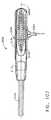
アンビル1130及びステープルカートリッジ1150が充分に配置された時点で、アンビル1130とステープルカートリッジ1150との中間に位置する組織をステープル留めし、及び/又は切開することができる。様々な実施形態において、図36を参照すると、外科用ステープル器具1100は、例えばステープルカートリッジ1150内でステープルスレッドアセンブリ1160を前進及び/又は後退させるように構成することができる押し込みバーアセンブリ1200を更に有し得る。少なくとも1つの実施形態において、押し込みバーアセンブリ1200は、押し込みバー1202及び発射アクチュエータ1204を有してよく、発射アクチュエータ1204は、押し込みバー1202及びステープルスレッドアセンブリ1160を遠位に動かすことによって上記に述べたようにステープルカートリッジ1150からステープルを発射し、アンビル1130にステープルを押し付けて変形させるように構成することができる。少なくとも1つの実施形態において、図44及び45を参照すると、ステープルスレッド1162は、押し込みバー1202の遠位端1201(図36)を受容するように構成することができ、遠位端1201に操作可能に接続され得る溝、溝部、又はスロット1161を有し得る。特定の実施形態では、ステープルスレッドアセンブリ1160は、ステープルカートリッジ1150がステープルカートリッジチャネル1122に挿入されると押し込みバー1202と操作可能に係合することができる。少なくとも1つの実施形態において、遠位端1201及びスロット1161は、遠位端1201とスロット1161とが横断方向に組み立てることは可能とするが、遠位端1201とスロット1161とが近位方向及び/又は遠位に互いから外れることは防止又は少なくとも抑制するような協働する構造を有し得る。他の実施形態では、押し込みバー1202を、ステープルスレッドアセンブリ1160と接触及び係合する前に遠位に前進させることができる。少なくとも1つのこのような実施形態では、ステープルスレッドアセンブリ1160は、押し込みバー1202が接触するまで静止したままでありうる。いずれの場合も、上記に概略述べたように、押し込み力及び/又は引張り力をアクチュエータ1204に加え、その力が押し込みバー1202に伝達されるようにアクチュエータ1204を押し込みバー1202に操作可能に連結することができる。特定の実施形態では、下記により詳しく述べるように、アクチュエータ1204を少なくとも第1の位置と第2の位置との間で選択的に回転させることができるように、アクチュエータ1204を押し込みバー1202の近位端1203に旋回可能に接続することができる。 Once the
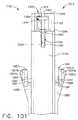
更に上記に加えて、図34、46及び47を参照すると、アクチュエータ1204は外科用ステープル器具1100の第1の側1116上の第1の位置(図46)と、第2の側1117上の第2の位置(図47)と、第1及び第2のハンドル部分1102及び1104の近位端1103及び1105に位置する中間位置(図34)との間で動かすことができる。アクチュエータ1204が第1及び第2の側1116、1117の一方の上の定位置へと回転させられた時点で、アクチュエータ1204を遠位に前進させることができる。異なる状況において、その結果、外科医が、アクチュエータ1204を第1の側1116又は第2の側1117に沿って遠位に動かすかを選択することができる。このような状況は、アクチュエータ1204が手術部位の周囲の組織により当たりやすい場合、例えば、アクチュエータ1204が他方の側面と比較して外科用器具の一方の側面に沿って遠位に動く場合に、生じうる。様々な実施形態において、図35及び36を参照すると、アクチュエータ1204は、アクチュエータ1204から延びるアーム1206を有し得、このアーム1206は押し込みバー1202の近位端1203に旋回可能に実装することが可能である。特定の実施形態では、再び図34、46及び47を参照すると、外科用器具1100は、第1の側1116に沿って延びる第1のスロット(図に示されていない)、及び第2の側1117に沿って延びる第2のスロット1118を有してよく、第1及び第2のスロットは、アクチュエータ1204の少なくとも一部分を摺動可能に受容するように構成することができる。少なくとも1つの実施形態では、第1及び第2のスロットの側壁が、所定の経路に沿ってアクチュエータ1204を動かすことができるようにアクチュエータ1204の運動を制限する、又は少なくとも制限する助けとなり得る。図47を参照すると、例えば第2のスロット1118は、アクチュエータ1204が第2の側1117に沿って遠位に動く際に、アクチュエータ1204のアーム1206が第1及び第2のハンドル部分の間で摺動できるように、第1のハンドル部分1102と第2のハンドル部分1104との間に成形することができる。上記と同様、第1のスロットも第1のハンドル部分と第2のハンドル部分との間に成形することができる。様々な実施形態において、再び図46及び47を参照すると、外科用器具1100は、アーム1206及び/又はアクチュエータ1204の他の任意の適当な部分をその内部で摺動させるようにやはり構成することができる中間スロット1119を更に有し得る。少なくとも1つのこのような実施形態では、中間スロット1119は、アクチュエータ1204がその中間位置にある場合にアクチュエータ1204をその第1及び第2の位置のいずれか一方に動かすことができるように、第1のスロットと第2のスロットとを接続することができる。特定の実施形態では、第1のスロット、第2のスロット1117、及び中間スロット1119は、互いに平行又は少なくとも実質的に平行であるか、及び/又は同一平面内にあってよいが、スロットの1つ又は2つ以上が他のスロットと平行でないか、及び/又は異なる平面内にあるような他の実施形態も考えられる。更に、例示の実施形態の第1及び第2の側は、外科用器具1100の反対の側面上に位置しているが、例えば第1及び第2のスロットが隣接する側面上、及び/又は互いに正反対ではない側面上に位置するような他の実施形態も考えられる。更に、丸みを帯びた、及び/又は円弧状の部分を有する器具のように、ステープル器具の側面同士が容易に区別できないような他の実施形態も考えられる。 In addition to the above, referring to FIGS. 34, 46 and 47, the
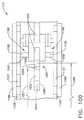
様々な実施形態において、更に上記に加えて、外科用ステープル器具1100は、アクチュエータ1204及びこれに応じてステープルスレッドアセンブリ1160が早まって前進させられることを防止又は少なくとも抑制することができるロック機構を更に有してもよい。少なくとも1つの実施形態では、ロック機構は、ラッチ機構1180が閉止位置又は少なくとも部分的閉止位置に動くよりも先にアクチュエータ1204が遠位に前進させられることを防止又は少なくとも抑制するように構成することができる。特定の実施形態では、図38を大まかに参照すると、外科用ステープル器具1100は、アクチュエータ1204と係合し、ラッチ機構1180が完全に開放位置(図38)及び/又は少なくとも実質的に開放位置にある間、アクチュエータ1204と係合した状態に保たれ得るロック機構1220を更に有し得る。様々な実施形態において、ロック機構1220は、例えばロックバネ1224によって加えられる付勢力によってアクチュエータ1204と係合した状態に付勢することができるロック1222を有し得る。少なくとも1つのこのような実施形態において、アクチュエータ1204は、ロック1222の少なくとも一部分を受容するように構成することができる1つ又は2つ以上の溝、溝部、又はスロットを有し得る(図に示されていない)。使用時には、ロック機構1220は、ラッチ機構1180が完全閉止位置(図40)及び/又は少なくとも実質的閉止位置に動くまで、アクチュエータ1204を定位置に保持することができる。このような状況では、少なくとも1つの実施形態において、ラッチ機構1180は、ロック機構1220と係合し、更にアクチュエータ1204からロック1222を外すように構成することができる。少なくとも1つのこのような実施形態において、図38〜40を参照すると、ラッチ機構1180は、ラッチ機構1180が閉止位置に動き、その結果、ロック1222をアクチュエータ1204から離れる方向に摺動及び/又は他の態様で動かす際に、ロック1222上のカム面1223と係合するように構成することができるカム1183を更に有し得る。様々な実施形態において、カム1183は、ラッチカバー1186及び/又はラッチフレーム1184から延びる壁、リブ、及び/又はリッジを含み得る。いずれも場合も、いったんロック1222がアクチュエータ1204から充分に外れると、少なくとも1つの実施形態では、アクチュエータ1204を図34に示される中間位置から図46及び47に示されるような第1及び第2の位置のいずれかに動かすことが可能となる。 In various embodiments, in addition to the above, the
上記に述べたように、ロック機構1220は、ラッチ機構1180が例えば閉止位置及び/又は部分的閉止位置などの所定の位置に動くよりも先に駆動バー1202が遠位に前進させられることを防止又は少なくとも抑制するように構成することができる。有利な点として、ロック機構1220は、第1のハンドル部分1102と第2のハンドル部分1104とが一緒に組み立てられるよりも先にステープルスレッドアセンブリ1160が前進させられることを防止又は少なくとも抑制することもできる。実際には、ロック機構1220は、アンビル1130とステープルカートリッジ1150との間に位置する組織が、アンビル1130及びステープルカートリッジ1150が組織に対して適切に配置されるよりも先に切開及び/又はステープル留めされることを防止することができる。また、実際には、ロック機構1220は、組織に適当な締め付け力が加えられるよりも先にステープルが組織内に発射されることを防止することができる。いずれの場合も、ラッチ機構1180が完全に開放位置及び/又は部分的開放位置に戻った時点で、カム1183をロック1222から離れる方向に動かすことによって、ロックバネ1124がロック1222を再びアクチュエータ1204と係合した状態に付勢することができる。異なる他の実施形態において、図38及び39を参照すると、ロック機構1220’は、カム面1223’、及び更に、ロック1222’の相対運動を制限することができる係止要素1226’を有するロック1222’を有し得る。少なくとも1つの実施形態において、図49に示されるように、例えばカム1183を、カム面1223’と接触するように構成することができ、カム表面1223’の外形成形された、面取りされた、及び/又は角度が付けられた表面によってロック1222’を遠位に駆動するようにカム1183を構成することができる。ロック1222’が遠位に駆動されることにより、ロック1222’から延びるピン1228’がアクチュエータ1204’の開口1229’内に位置する第2の位置(図49)と、ピン1228’が開口1229’から充分に引き抜かれている第1の位置(図48)との間でピン1228’を動かすことができる。様々な実施形態において、係止要素1226’は、ロック1222’が遠位に駆動され、ロック1222’が充分に変位した時点で係止要素1226’がカム1183と接触できるように構成することができる。このような実施形態では、係止要素1226’は、ロック1222’の第2の位置、即ち変位した位置を制御するように構成することができる。上記と同様、アクチュエータ1180が閉止位置から動かされ、カム1183がロック機構1220’から外れると、ロックバネ1224’がロック1222’を再びアクチュエータ1204’と係合した状態へと動かすことができる。 As noted above, the
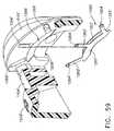
様々な実施形態において、上記に述べたように、発射アクチュエータを用いて押し込みバー、ステープルスレッド、及び/又は切開部材を第1の位置と第2の位置との間で動かすことができる。やはり上記に述べたように、例えば押し込みバーアセンブリ1200を用いて例えばステープルスレッドアセンブリ1160のようなステープルスレッドアセンブリを近位位置(図43)と、遠位位置との間で動かすことができる。特定の実施形態では、例えばステープルカートリッジ1150のようなステープルカートリッジが、内部に収容されたステープルスレッドアセンブリ1160を有してよく、その場合、ステープルスレッドアセンブリ1160は、ステープルカートリッジがステープルカートリッジチャネル1122に組み立てられるか又は挿入される際に図43に示されるような近位位置に位置し得る。少なくとも1つのこのような実施形態では、図41〜43を参照すると、ステープルカートリッジ1150は、例えばステープルスレッドアセンブリ1160が近位位置にある場合に切開部材1164の少なくとも一部分を覆うように構成することができるハウジング1170を更に有してもよい。異なる実施形態では、ハウジング1170は、例えば、外科医がステープルカートリッジを扱う際、ステープルカートリッジを外科用ステープラーに挿入する際、及び/又は、外科用ステープラーの2以上の部分を一緒に組み立てる際に、例えば外科医を保護するように構成することができる。少なくとも1つのこのような実施形態では、刃先1165の少なくとも上側部分が、ステープルカートリッジ1150のデッキ即ち上面1158よりも上方に延び、例えばハウジング1170のような保護ハウジングがなければ刃先1165の上側部分は露出する場合がある。 In various embodiments, as described above, a firing actuator can be used to move the push bar, staple sled, and / or cutting member between a first position and a second position. As also noted above, for example, push
様々な実施形態において、上記に述べたように、切開部材1165は、スロット又は溝部1156内に少なくとも部分的に配置され、図43に示されるように、切開部材1164の少なくとも上側部分即ち上部がデッキ1158の上方に延び得る。少なくとも1つの実施形態では、図41〜43を参照すると、ハウジング1170は、ステープルカートリッジ本体1152の第1の部分1157から延びる第1の壁又は部分1172、ステープルカートリッジ本体1152の第2の部分1159から延びる第2の壁又は部分1174、及び第1の壁1172と第2の壁1174との間に延びる上部壁又は部分1176を有し得る。特定の実施形態では、ハウジングは、ステープルカートリッジ本体から延びる1つのみの支持壁又は支持部分、及び更に、支持壁から延びる上部壁又は上部を有し得る。他の実施形態では、ハウジングは1つ又は2つ以上の側壁又は部分を有し、上部壁は有さないものとすることができる。少なくとも1つのこのような実施形態では、ハウジングの側壁を、例えば切開部材の上部の上方に延びるか、又は切開部材の刃先の上方に少なくとも延びるように構成することができる。いずれの場合も、図43に示されるように、ステープルスレッドアセンブリ1160が近位位置にある場合、切開部材1164の少なくとも一部分が上部壁1176の下で、及び/又は側壁1172と1174との間に位置し得る。特定の実施形態では、切開部材1164はその全体が上部壁1176の下で、及び/又はその全体がハウジング1170の内部に位置し得る。少なくとも1つの実施形態では、切開部材1164は、切開面1165が上部壁1176の遠位縁1175及び/又は近位縁1177を越えて延びないように上部壁1176の下に配置することができる。少なくとも1つの実施形態では、ハウジング1170は、切開部材1164及び/又はステープルスレッドアセンブリ1160の他の任意の部分の近位方向への運動を制限するように構成することができる後部壁1178を有し得る。様々な実施形態において、例えばハウジング1170の少なくとも一部分を、ステープルカートリッジ本体1152と一体に成形することができる。少なくとも1つのこのような実施形態では、第1の壁1172、第2の壁1174、上部壁1176、及び/又は後部壁1178を、ステープルカートリッジ本体1152が例えば射出成形される際に成形することができる。特定の実施形態では、ハウジング1170の少なくとも一部分を、スナップ嵌め機構、圧入機構、及び/又は他の任意の適当な手段によってステープルカートリッジ本体1152に組み立てることができる。 In various embodiments, as described above, the dissecting
様々な実施形態において、更に上記に加えて、切開部材1164は、切開部材本体の少なくとも1つの辺に沿って延びるナイフ刃先を有する平面状又は少なくとも実質的に平面状の本体によって成形することができる。少なくとも1つのこのような実施形態において、第1壁1172及び/又は第2の壁1174は、切開部材1164の側面に対して平行又は少なくとも実質的に平行で、平面状、又は少なくとも実質的に平面状の内面1173を有し得るように構成及び配置することができる。特定の実施形態では、切開部材1164は、壁1172及び1174の各内面1173の間に密接して受容され得る。少なくとも1つのこのような実施形態では、壁1172と1174との間の距離は、スロット1156の幅と同じか、又は少なくとも実質的に同じであってよい。いずれの場合も、ハウジングは、例えばハウジングの少なくとも一部分がスロット1156の少なくとも一部分を覆って延びるように構成することができる。特定の実施形態では、ハウジング1170は、切開部材1164及び/又は切開面1165を完全に囲繞又は包囲することができる。少なくとも1つの実施形態において、図には示されていないが、ハウジングは切開部材をハウジングから出せるように少なくとも部分的に分離、脱離、又は他の態様で変形させることが可能な切欠き及び/又は切開可能な部分を有し得る。少なくとも1つのこのような実施形態において、組織切開面は、例えば、ハウジングと接触してハウジングの壁を破断及び/又は切開するように構成することができる。異なる態様において、ハウジングの壁は、肉薄部分、厚みの小さい部分、刻み線、及び/又は、ハウジングの壁の変形及び/又は切開を容易とする他の任意の構成を有し得る。特定の実施形態では、切開部材は、ハウジングを変形及び/又は切開するように構成することができる例えば1つ又は2つ以上の更なる切開面及び/又はアンビルを有し得る。少なくとも1つの実施形態では、ハウジングは、切開部材を通過させるように充分に移動及び/又は屈曲するように構成することができる、例えばヒンジ部材及び/又は可撓性フラップのような可動性及び/又は可撓性部分を有し得る。いずれの場合も、切開部材が組織を切開するのに適した任意の構成を有し、保護ハウジングが切開部材を少なくとも部分的に囲繞又は包囲するのに適した任意の構成を有し得る実施形態が考えられる。更に、切開部材は上記に述べたような鋭利な刃先を有し得るものであるが、例えば組織を切開するうえで充分な電流が供給されるものなど、他の適当な切開部材も考えられる。 In various embodiments, in addition to the above, the cutting
上記に述べたように、ハウジング1170は、ハウジング1170が近位位置にある場合に切開部材を少なくとも部分的に被覆、囲繞及び/又は包囲するように構成することができる。様々な実施形態において、切開部材を遠位に前進させることによって例えば組織を切開した後、近位に後退させることによって切開部材を再びハウジング1170内に配置することができる。このような実施形態では、ステープルカートリッジが外科用ステープル器具に組み立てられ、外科用ステープル器具から取り外される際に切開部材をハウジング1170によって少なくとも部分的に覆うことができる。特定の実施形態では、新しい、即ち未使用のステープルカートリッジをステープルカートリッジチャネルに挿入して少なくとも部分的に使用されたステープルカートリッジを交換することができる。少なくとも1つのこのような実施形態においては、新しいステープルカートリッジは、その内部に配置された新しい切開部材及び/又はステープルスレッドアセンブリを有し得るが、既に使用された切開部材及び/又はステープルスレッドアセンブリを使用済みステープルカートリッジから充分に引き抜いて、新しいステープルカートリッジ内に進めることによってまた再使用することができる実施形態も考えられる。それぞれの新しいステープルカートリッジについて新しい切開部材及び/又はステープルスレッドアセンブリが与えられるような実施形態では、例えばそれぞれのステープルカートリッジで鋭利な刃先を使用することができる。 As noted above, the
異なる実施形態では、図には示されていないが、ステープルカートリッジは、切開部材が2以上の位置にある場合に少なくとも部分的に切開部材を覆うように構成された2以上のハウジングを有し得る。少なくとも1つの実施形態では、ステープルカートリッジは、切開部材が例えば近位位置にある場合に切開部材を少なくとも部分的に覆うように構成された近位のハウジングと、更に、切開部材が例えば遠位位置にある場合に切開部材を少なくとも部分的に覆うように構成された遠位側ハウジングとを有し得る。少なくとも1つのこのような実施形態では、ステープルカートリッジが外科用ステープル器具に組み立てられる際に切開部材を近位のハウジング内に配置することができ、特定の実施形態では、切開部材が例えばエンドエフェクタ内に位置する組織を横方向に切開した後、切開部材を遠位側ハウジング内に進めることができる。このような実施形態では、その結果、ステープルカートリッジが外科用ステープラーから取り外される際に切開部材は遠位側ハウジング内に少なくとも部分的に配置され得る。このような実施形態は、例えば脈管がステープルカートリッジの近位のハウジングと遠位側ハウジングとの間に配置されるような場合に特に有用となり得る。様々な実施形態において、図には示されていないが、切開部材を、所定の遠位位置から所定の近位位置、及び/又は他の任意の位置へと近位に動かすことができる。 In different embodiments, although not shown in the figures, the staple cartridge may have two or more housings configured to at least partially cover the cutting member when the cutting member is in two or more positions. . In at least one embodiment, the staple cartridge includes a proximal housing configured to at least partially cover the cutting member when the cutting member is in a proximal position, for example, and further wherein the cutting member is in a distal position, for example. And a distal housing configured to at least partially cover the dissection member. In at least one such embodiment, the cutting member can be disposed within the proximal housing when the staple cartridge is assembled to the surgical stapling instrument, and in certain embodiments, the cutting member can be, for example, within an end effector. After the transverse incision of the tissue located at, the dissection member can be advanced into the distal housing. In such embodiments, as a result, the cutting member may be at least partially disposed within the distal housing as the staple cartridge is removed from the surgical stapler. Such an embodiment may be particularly useful when, for example, the vessel is disposed between the proximal housing and the distal housing of the staple cartridge. In various embodiments, not shown in the figures, the cutting member can be moved proximally from a predetermined distal position to a predetermined proximal position and / or any other position.
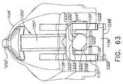
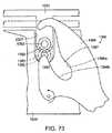
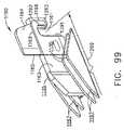
様々な実施形態において、上記に述べたように、ステープルカートリッジ1150をステープルカートリッジチャネル1122に挿入することができる。次に図92を参照すると、ステープルカートリッジ1150の近位端1213をステープルカートリッジチャネル1122の近位端1123内に配置することができる一方で、ステープルカートリッジ1150の遠位端1211をステープルカートリッジチャネル1122の遠位端1121内に配置することができる。少なくとも1つの実施形態において、ステープルカートリッジチャネル1122の遠位端1121は、例えばステープルカートリッジ1150の遠位端1121の1つ又は2つ以上の突起及び/又は1つ又は2つ以上の凹部と対応するように整列させることができる1つ又は2つ以上の突起及び/又は1つ又は2つ以上の凹部を有し得る。少なくとも1つのこのような実施形態において、ステープルカートリッジチャネル1122の各側壁1124は、突起又はタブ1279及び凹部又はスロット1278を有してよく、その場合、ステープルカートリッジ1150の各側面は、図95を参照すると、凹部1278内に配置されるように構成された突起部1274と、更に、突起部1279を受容するように構成された凹部1270とを有し得る。様々な実施形態において、ステープルカートリッジ1150の各凹部1270は、対向する側壁1272及び1273、並びに遠位面1271を有してよく、その場合、ステープルカートリッジ1150がステープルカートリッジチャネル1122内に配置される際に遠位面1271がその内部に配置される突起部1279と当接するように配置され得る。異なる状況において、下記により詳しく述べるように、凹部1270の遠位面1271は、ステープルカートリッジ1150の特定の成形部を予め決定することができる基準面として機能し得る。いくつかの状況では、ステープルカートリッジ1150の遠位端1211は、ステープルカートリッジ1150の近位端1213がステープルカートリッジチャネル1122の近位端1123に挿入される前にステープルカートリッジチャネル1122の遠位端1121と整列させ、及び/又は遠位端1121に挿入することができる。例えば、突起部1279が凹部1270内に配置されるようにステープルカートリッジチャネル1150の遠位端1211をステープルカートリッジチャネル1122と整列させることができ、この後、ステープルカートリッジ1150をステープルカートリッジチャネル1122の方向に揺り動かすか又は回転させることにより、ステープルカートリッジ1150の近位端1213をステープルカートリッジチャネル1122の近位端1123に挿入することができる。 In various embodiments, the
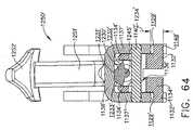
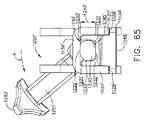
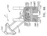
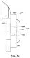
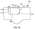
上記に述べたようにステープルカートリッジ1150の遠位端1211がステープルカートリッジチャネル1122の遠位端1121と嵌合した時点で、突起部1274をステープルカートリッジチャネル1122の突起部1278の下に引っ掛けることによってステープルカートリッジ1150の突起部1274をステープルカートリッジチャネル1122の凹部1279に挿入することができる。このような状況では、突起部1274及び1278と凹部1270及び1279とが協働することで、ステープルカートリッジ1150の遠位端1211がステープルカートリッジ1122の遠位端に取り付けられ、更に、ステープルカートリッジ1150がステープルカートリッジチャネル1122と整列されることにより、ステープルカートリッジ1150をステープルカートリッジチャネル1122の各側壁1124間に挿入することができる。ステープルカートリッジ1150の遠位端1211がステープルカートリッジチャネル1122に引っ掛けられた時点で、ステープルカートリッジ1150及びステープルカートリッジチャネル1122の少なくとも一方を他方に対して回転させることができる。異なる状況において、図92及び95を再び参照すると、ステープルカートリッジ1150をステープルカートリッジチャネル1122の方向に旋回させることによってステープルカートリッジチャネル1150内の整列スロット1280をサイドフランジ1128と整列させることができる。様々な実施形態において、ステープルカートリッジ1150はその両側に、サイドフランジ1128を受容するようにそれぞれを構成することができる整列スロット1280を有し得る。少なくとも1つの実施形態において、各整列スロット1280は、横側壁1283及び1284、並びに側壁1283と1284との間に延びる底壁1281を有し得る。更に上記に加え、凹部1270の遠位基準面1271から整列スロット1280の遠位側底壁1281までは所定の距離1289とすることができる。次に図93及び95を参照すると、突起部1279の遠位端とサイドフランジ1128の遠位端との間の所定の距離1288は、凹部1270の遠位面1271と整列スロット1280の底壁1281との間の距離1289よりも短くなるようにすることができる。距離1288が距離1289よりも短いため、上記に述べたようにサイドフランジ1128が整列スロット1280内に入るようにステープルカートリッジ1150を定位置に回転させることができる。様々な実施形態において、整列スロット1280は、例えばサイドフランジ1128と整列スロット1280の側壁との間の相対運動があったとしてもごくわずかであるようにサイドフランジ1128が側壁1283と1284との間に密接して受容されるようなサイズ及び構成とすることができる。 As described above, when the
異なる代替的な実施形態では、更に上記に加えて、ステープルカートリッジ1150の近位端1213をステープルカートリッジチャネル1122の遠位端1121に挿入して側壁1124の間を近位に摺動させることにより、ステープルカートリッジチャネル1150の近位端1213がステープルカートリッジチャネル1122の近位端1123内に入るようにすることができる。このような摺動運動の間に、サイドフランジ1128が整列スロット1280内に入り、更に突起部1279が凹部1270内に入ることができる。特定の実施形態では、ステープルカートリッジ1150をステープルカートリッジチャネル1122内へと摺動かつ回転させて入れることができる。いずれの場合も、様々な実施形態において、ステープルカートリッジ1150及びステープルカートリッジチャネル1122は、ステープルカートリッジ1150がステープルカートリッジチャネル1122内に着脱可能に固定されるように構成することができる。少なくとも1つの実施形態において、次に図95及び100を主に参照すると、ステープルカートリッジ1150は、ステープルカートリッジチャネル1122の1つ又は2つ以上の保持要素と解放可能に嵌合するように構成することができる1つ又は2つ以上の保持要素を有し得る。より詳細には、少なくとも1つのこのような実施形態において、ステープルカートリッジ1150は、ステープルカートリッジチャネル1122の1つ又は2つ以上の保持キー1195と嵌合するように構成することができる1つ又は2つ以上の保持スロット1190を有し得る。様々な実施形態において、図95を再び参照すると、各保持スロット1190は、保持キー1195を内部に受容するように構成することができる第1の、又は入口部分1191、及び更に、保持キー1195が入口部分1191を通過した後、保持キー1195を受容するように構成することができる第2の部分1192を有し得る。特定の実施形態において、入口部分1191は、保持スロット1190の近位側面1193と遠位側面1194との間の第1の幅を画定し、更に、第2の部分1192は、近位側面1193と遠位側面1194との間の、入口部分1191の第1の幅よりも広い第2の幅を画定し得る。様々な実施形態において、入口部分1191の第1の幅は、保持キー1195の幅よりも狭くてもよく、第2の部分1192の第2の幅は、保持キー1195の幅よりも広くてもよい。少なくとも1つのこのような実施形態において、保持スロット1190は、圧入及び/又はスナップ嵌め方式の少なくとも一方によって保持キー1195と嵌合するように構成することができる。特定の実施形態において、近位側面1193及び/又は遠位側面1194の少なくとも一方を、保持キー1195が保持スロット1190に挿入される際に外側に撓むか又は拡がるように構成することができる。少なくとも1つのこのような実施形態において、近位側面1193が近位に変位するようにすることができる。いずれの場合も、図100を参照すると、保持スロット1190が保持キー1195を受容した時点で、保持スロット1190の近位側面1193が保持キー1195の近位側面1196上に位置し、保持スロット1190の遠位側面1194が保持キー1195の遠位側面1197上に位置し得る。 In another alternative embodiment, in addition to the above, by inserting the
上記に概略述べたように、ステープルカートリッジ1150は、ステープルカートリッジ1150の遠位端1211をステープルカートリッジチャネル1122の遠位端1121と連結し、次いでステープルカートリッジ1150の近位端1213をステープルカートリッジチャネル1122の近位端1123内へと回転させることによってステープルカートリッジチャネル1122内に組み立てることができる。少なくとも1つのこのような実施形態において、保持スロット1190は、ステープルカートリッジ1195がステープルカートリッジチャネル1122内の固定位置に回転させられる際に保持キー1195と嵌合するように構成することができる。次に図93を参照すると、凹部1270の遠位基準面1271と保持スロット1190との間の所定の距離1199は、ステープルカートリッジ1150が上記に述べたように定位置へと回転させられる際に保持スロット1190が保持キー1195と整列されるようなサイズ及び構成とすることができる。これに対応して、少なくとも1つの実施形態において、突起部1279の遠位端と保持キー1195との間の距離を距離1199に等しい、又は少なくとも実質的に等しいものとすることができる。異なる状況において、上記に述べた距離は、保持スロット1190及び保持キー1195を含む要素の中心までの距離とすることができる。例えば距離1199は、例えばスロット1190の近位側壁と遠位側壁との間の中心の位置までの距離とすることができる。様々な実施形態において、保持スロット1190は、保持キー1195を保持スロット1190内に案内又は方向付けするように構成することができる、導入表面、斜角が付けられた表面、及び/又は丸味が付けられた表面を更に有し得る。少なくとも1つのこのような実施形態では、これらの導入表面は第1の部分1191よりも幅広であり得る。 As outlined above, the
ステープルカートリッジ1150がステープルカートリッジ1122内に回転させられると、ステープルカートリッジ1150内に配置された切開部材及び/又はステープル発射スレッドが押し込みバー1202と操作可能に係合し得る。より詳細には、次に図97〜99を参照すると、ステープルカートリッジ1150は、ステープルカートリッジ1150がステープルカートリッジチャネル1122内に配置された後、上記に述べたように押し込みバー1202及び切開部材1160を一緒に前進させることができるように押し込みバー1202と操作可能に連結することが可能な切開部材1160を有し得る。少なくとも1つの実施形態では、切開部材1160は、押し込みバー1202の遠位端の遠位側駆動突起部1294(図93)を受容するように構成することができるスロット1161を有し得る。より詳細には、次に図101を参照すると、切開部材1160のスロット1161をステープルカートリッジ1150の底部のアクセススロット1290と整列させることによって、ステープルカートリッジ1150の近位端1213がステープルカートリッジチャネル1122の近位端1123内に配置される際に、押し込みバー1200の駆動突起部1294がアクセススロット1290を通って切開部材1160のスロット1161内に延びることができる。様々な実施形態において、スロット1161及び駆動突起部1294は、それらの間に相対運動があったとしてもごくわずかであるようなサイズ及び構成とすることができる。より詳細には、図98及び99を再び参照すると、スロット1161は、遠位側壁1291及び近位側壁1292を有してよく、駆動突起部1294は側壁1291と1292との間にしっかりと受容され得る。様々な実施形態において、再び図93及び101を参照すると、押し込みバー1202は、駆動突起部1294に対して近位に配置された凹部即ちスロット1295を更に有してよく、スロット1295は切開部材1160から延びる近位突起部1293(図97)を受容するように構成することができる。上記と同様、スロット1295は、近位突起部1293を密接に受容することによってそれらの間に相対運動があったとしてもごくわずかであるように構成することができる側壁によって画定され得る。 As
上記に述べたように、切開部材1160のスロット1161は、ステープルカートリッジ1150がステープルカートリッジチャネル1122内に配置される際に押し込みバー1202の駆動突起部1294と整列するようにステープルカートリッジ1150内に配置することができる。次に図96を参照すると、凹部1270の遠位面1271とスロット1161との間に所定の距離1299が画定されるが、距離1299は、突起部1279の遠位端と駆動突起部1294との間の所定の距離1297に等しいか、又は少なくとも実質的に等しくてよい。異なる状況において、切開部材1160は、切開部材1160がハウジング1170内に位置する最近位端位置と、切開部材1160が切開スロット1156を通じて前進させられた後の最遠位位置との間の一定範囲の位置を通じて動かすことができる。様々な実施形態において、距離1299は、切開部材1160が最近位位置にある場合の切開部材1160に対する距離とすることができる。上記と同様、距離1297及び1299は、それぞれ駆動突起部1297及びスロット1161の中心又は中間点までの距離とすることができる。様々な実施形態において、外科用器具1100は、切開部材1160が駆動突起部1294と係合している間、押し込みバー1202を定位置に保持するように構成することが可能なロック機構を更に有し得る。上記と同様、特定の実施形態では、突起部1279の遠位端と押し込みバー1202の凹部1295との間の距離1298を画定することができるが、距離1298は、凹部1270の遠位面1271と切開部材1160の突起部1293との間の距離に等しいか又は少なくとも実質的に等しくてよい。様々な実施形態において、次に図97及び100を主に参照すると、ステープルカートリッジ1150は、ステープルカートリッジ本体1152の近位端1295と、ステープルカートリッジパン1154の近位端1294との間に画定されるクリアランス領域を有してもよく、このようなクリアランス領域は、例えば押し込みバー1202及び/又はステープルカートリッジチャネル1122の一部分を受容するように構成することができる。いずれの場合も、押し込みバー1202が切開部材1160と係合した時点で押し込みバー1202を遠位に前進させることが可能であり、このような運動が、例えば近位位置(実線で示される)及び第2の、遠位位置(破線で示される)にある押し込みバー1202の遠位端1201を示した図100に示されている。 As described above, the
様々な実施形態において、上記に述べたように、ステープルカートリッジ1150の遠位端1211をステープルカートリッジチャネル1122の遠位端1121と嵌合させてからステープルカートリッジチャネル1122内に旋回させることによってステープルカートリッジ1150の近位端1213をステープルカートリッジチャネル1122の近位端1123内に配置することができる。このようなプロセスでは、ステープルカートリッジ1150の突起部1274をステープルカートリッジチャネル1122の突起部1276の下に係合させた後、上記に述べたようにして、整列スロット1280がフランジ1182と隣接した位置となるまでステープルカートリッジ1150を回転させることを行い得る。この時点では、様々な実施形態において、切開部材1160が押し込みバー1202と係合しておらず、更に、保持スロット1190が保持キー1195と係合していなくともよい。このため、外科医又は臨床医は、ステープルカートリッジチャネル1122内のステープルカートリッジ1150の位置を、ステープルカートリッジ1150が定位置にロックされる前に調節することができる。サイドフランジ1182が整列スロット1280内に少なくとも部分的に配置された時点で、近位端1213をステープルカートリッジチャネル1122の方向に更に回転させることができる。この時点で、切開部材1160が押し込みバー1202と操作可能に係合し、更に保持スロット1190が保持キー1195と係合することができる。様々な実施形態において、切開部材1160は、保持スロットが保持キー1195と係合するのと同時、又は少なくとも実質的に同時に押し込みバー1202と操作可能に係合し得る。より詳細には、少なくとも1つの実施形態において、押し込みバー1202の駆動突起部1294は、保持キー1195がスロット1190の第2の部分1192内に導入されるか又はスナップ嵌めされるのと同時に切開部材1160のスロット1161に導入され得る。少なくとも1つのこのような実施形態において、切開部材1160は、ステープルカートリッジ1150が定位置にスナップ嵌め、又は配置されるまで、押し込みバー1202によって前進させることができなくともよい。特定の代替的な実施形態では、切開部材1160は、ステープルカートリッジ1150の近位端1123がステープルカートリッジチャネル1122の近位端1213内に配置される際に保持キー1195が保持スロット1190内に完全に配置される前に、押し込みバー1202と操作可能に係合させることができる。様々な実施形態において、各保持スロット1190は、保持キー1195と同時、又は少なくとも実質的に同時に係合するように互いに対して整列させることができる。少なくとも1つのこのような実施形態において、保持スロットは、各保持キー1195が保持スロット1190の第2の部分1192に同時に導入されるように構成することができる。少なくとも1つの実施形態において、保持スロット1190は、切開スロット1156によって画定される長手方向軸に対して横断方向又は垂直な軸に沿って配置することができる。様々な実施形態において、保持スロット1190、及びそれらの間に画定される軸は、例えば切開部材1160が最近位位置にある場合を含み、切開部材1160の位置に関わらず切開部材1160に対して近位に位置し得る。 In various embodiments, as described above, the
様々な実施形態において、切開スロット1156は、その第1の側の本体部分1152a及びその第2の側、即ち反対1152b側の第2の本体部分1152bを画定することができる。図95及び98を参照すると、第1の本体部分1152aは第1の複数のステープル穴1151を有し、更に第2の本体部分1152bは第2の複数のステープル穴1151を有してもよい。少なくとも1つの実施形態において、第1の本体部分1152aは、第1の本体部分1152aの他のステープル穴1151に対して近位に配置され得る最近位のステープル穴1151aを有し得る。少なくとも1つの実施形態では、ステープル穴1151aの全体が第1の本体部分1152aの整列スロット1280の底壁1281に対して近位に配置され得るのに対して、他の実施形態では、ステープル穴1151aの少なくとも一部分が底壁1281に対して近位に配置され得る。図97に示されるように、第1の本体部分1152aの整列スロット1280は、最近位のステープル穴1151aに対して側部に、更に切開スロット1156に対して側部に配置されている。更に上記に加えて、第1の本体部分1152aは、最近位のステープル穴1151aを除く第1の本体部分1152aの他のステープル穴1151に対して近位に配置され得る2番目に近位のステープル穴1151cを有し得る。少なくとも1つの実施形態では、ステープル穴1151cの全体が第1の本体部分1152aの整列スロット1280の底壁1281に対して近位に配置され得るのに対して、他の実施形態では、ステープル穴1151cの少なくとも一部分が底壁1281に対して近位に配置され得る。図97を参照すると、第1の本体部分1152aの整列スロット1280は、2番目に近位のステープル穴1151cに対して少なくとも部分的に側部に配置されている。引き続き図97を参照すると、第1の本体部分1152aは、例えばステープル穴151a及び1151cを含むステープル穴1151に対して近位に配置され得る保持スロット1190を有し得る。 In various embodiments, the
図95を参照すると、更に上記に加えて、第2の本体部分1152bは、第2の本体部分1152bの他のステープル穴1151に対して近位に配置され得る最近位のステープル穴1151bを有し得る。少なくとも1の実施形態では、ステープル穴1151bの全体が第2の本体部分1152bの整列スロット1280の底壁1281に対して近位に配置され得るのに対して、他の実施形態では、ステープル穴1151bの少なくとも一部分が底壁1281に対して近位に配置され得る。図95に示されるように、第2の本体部分1152bの整列スロット1280は、最近位のステープル穴1151b及び切開スロット1156に対して側部に配置されている。更に上記に加えて、第2の本体部分1152bは、最近位のステープル穴1151bを除く第2の本体部分1152bの他のステープル穴1151に対して近位に配置され得る2番目に近位のステープル穴1151dを有し得る。少なくとも1つの実施形態では、ステープル穴1151dの全体が第2の本体部分1152bの整列スロット1280の底壁1281に対して近位に配置され得るのに対して、他の実施形態では、ステープル穴1151dの少なくとも一部分が底壁1281に対して近位に配置され得る。図95に示されるように、第2の本体部分1152bの整列スロット1280は、2番目に近位のステープル穴1151dに対して少なくとも部分的に側部に配置されている。引き続き図95を参照すると、第2の本体部分1152bは、例えばステープル穴1151b及び1151dを含むステープル穴1151に対して近位に配置され得る保持スロット1190を有し得る。 Referring to FIG. 95, in addition to the above, the
様々な実施形態において、更に上記に加えて、ステープルカートリッジ本体1152はプラスチックで構成することができ、射出成形プロセスを用いて成形することができる。その後、様々な実施形態において、ステープルドライバ1168(図42)をステープル穴1151内に組み立て、上記に述べたように切開部材1164がハウジング1170内に位置するように切開部材1160をカートリッジ本体1152内に配置することができる。次いでステープルカートリッジパン1154をステープルカートリッジ本体1152に組み立てることができる。様々な実施形態において、次に図96を参照すると、ステープルカートリッジパン1154の遠位端1277をステープルカートリッジ本体1152の近位端1295と整列させることにより、ステープルカートリッジ本体を例えばステープルカートリッジパン1154内で対向する壁1154aと1154bとの間で摺動させることができる。ステープルカートリッジ本体1152とパン1154とは、パン突起部1276が凹部1270内に配置され、突起部1274がパン凹部1275内に配置されるまで互いに対して摺動させることができる。これと同時に、ステープルカートリッジ本体1152から延びるロック突起部1288が、ステープルカートリッジパン1154のロック穴1287内に受容されることによって、パン1154をステープルカートリッジ本体1152に対してロックすることができる。様々な実施形態において、パン1154の側壁1154a及び1154bは、ロック突起部1288上を通過する際に外側に撓むか又は拡がり、ロック穴1287がロック突起部1288と整列すると内側に弾性的に戻ることができる。この時点で、パン1154から延びるアーム1155がステープルカートリッジ本体1152の保持スロット1287と整列し、その内部に配置され得る。特定の実施形態では、ここで図101を参照すると、ステープルカートリッジ1150は、例えばステープルカートリッジ本体1152のスロット1301を選択的に塞ぐように構成することができる例えば保持部材1300のような保持部材を更に有し得る。少なくとも1つの実施形態において、保持部材1300は、スロット1301をまたぐように延びる第1の位置(実線で示される)と、スロット1301に隣接して配置される第2の位置(破線で示される)との間で回転させることができる旋回可能なアーム1303を含みうる。少なくとも1つのこのような実施形態では、一体成形された旋回ピン1302(図95)が、アーム1303から、アーム1303をその周りに回転させることができる軸線を画定し得るステープルカートリッジ本体1152の開口の内部へと延びうる。特定の実施形態では、アーム1303は、ステープルカートリッジ本体1152のロック穴1305と解放可能に係合されることによってアーム1303を例えば第1及び第2の位置の少なくとも一方に保持するように構成することができる、アーム1303から延びるロック部材1304を有し得る。特定の実施形態では、スロット1301をまたぐようなアーム1303の配置によって、例えば切開部材1160がステープルカートリッジ1150から滑り出ることを防止、又は少なくとも抑制することができる。 In various embodiments, in addition to the above, the
ステープルカートリッジ1150のステープルカートリッジチャネル1122への挿入又はステープルカートリッジチャネル1122からの取り出しを容易とするため、様々な実施形態において、ステープルカートリッジ1150は、例えばその両側に配置された把持部分を有し得る。少なくとも1つの実施形態において、次に図97及び101を参照すると、ステープルカートリッジ本体1152は、整列スロット1280に隣接して配置された外側部分1285を有してよく、臨床医が外側部分1285を把持及び/又は押すことによって、例えばステープルカートリッジ1150の近位端1213をステープルカートリッジチャネル1122の近位端内に配置することができる。ステープルカートリッジ1150の近位端1213が上記に述べたような位置に回転させられる際にこのような力を外側部分1285の上面、即ち組織接触面に加えることができる。様々な実施形態において、ステープルカートリッジ1150の近位端1213をステープルカートリッジチャネル1122から持ち上げるために、外側部分1285に持ち上げるような力を加えてもよい。少なくとも1つのこのような実施形態において、主に図101を参照すると、各外側部分1285は、外側部分1285に対する臨床医の把持性を高めるように構成することができる、例えば1以上の段差部、突出部並びに/又は、隆起部1287a、1287b及び/若しくは1287cのような隆起部を有し得る。様々な実施形態において、隆起部1287a、1287b及び1287c/又は1287cは、互いに対して異なる高さに配置することができる。いずれの場合も、ステープルカートリッジ1150は、例えば、ステープルカートリッジ1150の近位端1213を溝部1122から持ち上げ、次いでステープルカートリッジ1150の遠位端1211を溝部1122の遠位端1121から外すか又は係脱させることによって溝部1122から取り出すことができる。ステープルカートリッジ1150が溝部1122から取り出されると、例えば切開部材1160内のスロット1161を押し込みバー1202の駆動突起部1294から離れる方向に動かして駆動突起部1294から外すことができる。 To facilitate insertion or removal of the
異なる状況において、更に上記に加えて、ステープルカートリッジ1150をステープルカートリッジチャネル1122から取り出す前に押し込みバー1202及び切開部材1160をそれらの近位位置に戻すことができる。このような位置では、上記に述べたように、刃先1165はハウジング1170内に位置することができる。様々な実施形態において、次に図102を参照すると、ステープルカートリッジ1150’の代替的な実施形態がハウジング1170のない状態で示されている。少なくとも1つのこのような実施形態では、刃先1165は、例えば、その近位位置及び/又は遠位に前進させられた他の任意の位置において、ステープルカートリッジ本体1152のデッキ面1158よりも上方に少なくとも部分的に延び得る。 In different situations, and in addition to the above,
様々な実施形態において、更に上記に加えて、アンビル1130は、例えばアンビル1130がステープルカートリッジ1150と近接対向した位置に動く際に、ハウジング1170の少なくとも一部分を受容するように構成することができる1つ又は2つ以上の開口、スロット又は凹部1179(図50)を有し得る。少なくとも1つの実施形態において、ハウジング1170と凹部1179との間に充分なクリアランスが存在することにより、アンビル1130とステープルカートリッジ1150とを、それらが干渉することなく、又は少なくとも実質的に干渉することなく互いに対して動かすことができる。上記に概略述べたように複数の切開部材ハウジングを有する実施形態では、対向するアンビルは、各ハウジングを受容するための複数の対応する開口を有し得る。様々な実施形態において、アンビルは、可動切開部材、及び該切開部材を少なくとも部分的に被覆、囲繞及び/又は包囲するための少なくとも1つのハウジングを有し得る。特定の実施形態において、図に示されてはいないが、アンビル及びステープルカートリッジの両方が、少なくとも1つの可動切開部材、及び/又は、例えば切開部材が近位位置にある場合に切開部材を少なくとも部分的に被覆、包囲又は囲繞するように構成された少なくとも1つのハウジングを有し得る。 In various embodiments, in addition to the above, the
上記に概略述べたように、押し込みバーアセンブリ1200を遠位側に動かすことによってステープルスレッドアセンブリ1160をステープルカートリッジアセンブリ1150内で動かすことができる。様々な実施形態において、やはり上記に概略述べたように、ステープルスレッド1162の楔状カム面1167をステープルドライバ1168の傾斜面1169と係合するように動かすことによって、ステープルカートリッジ1150から順次及び/又は同時にステープルをアンビル1130に対して打ち出し、ステープルを例えばB字形状の形態などの任意の適当な形態に成形することができる。少なくとも1つのこのような実施形態では、図50を参照すると、アンビル1130は、ステープルを変形させるように構成することができる例えばステープルポケット1132のような1つ又は2つ以上のステープル成形面を有し得る。特定の実施形態では、アンビル1130は、例えばステープルスレッド1162、切開部材1164、及び/又は押し込みバー1202の少なくとも一部分を摺動可能に受容するように構成することが可能なスロット、溝部、又は溝1133を更に有し得る。少なくとも1つの実施形態では、図には示されていないが、アンビルは、アンビル内部に成形されたアンビル溝部内にしっかりと及び/又は不動に配置され得るアンビルプレートを有してもよい。異なる他の実施形態において、図51及び52に示され、下記により詳しく述べるように、アンビル1130は、アンビル溝部1136内に移動可能に配置されるアンビルプレート1134を有し得る。特定の実施形態では、アンビル溝部1136は、対向する側壁1137及び更に各側壁1137間に延びる底部1138を有し得る。少なくとも1つの実施形態では、アンビル1130は、アンビル1130に組み立てられた例えば遠位側ノーズ部分1139を更に有してよく、ノーズ部分1139は例えばアンビル溝部1136内に圧入及び/又はスナップ嵌めされることでアンビル溝部1136内にしっかりと保持され得るように構成することができる。特定の実施形態では、ノーズ部分1139は、軟質及び/又は柔軟な例えばゴムなどの材料で構成することができ、例えば手術部位へのアンビル1130の挿入を促進し得る任意の適当な形状を有し得る。いくつかの実施形態では、図51を参照すると、ノーズ部分1139’のようなノーズ部分は、1つ又は2つ以上の締結要素1139a’によってアンビルに対して保持され得る。同様に図34を参照すると、例えば、ステープルカートリッジチャネル及び/又はステープルカートリッジ1150のようなステープルカートリッジは、例えば手術部位へのステープルカートリッジ1150の挿入を促進し得る例えばノーズ部分1153のようなノーズ部分を有し得る。 As outlined above, the
上記に述べたように、ステープルは、ステープルカートリッジから発射されてアンビルに押し付けられて変形させられる。異なる状況において、アンビル1130上のステープル成形面とステープルスレッド1162との間の距離によってステープルが変形される量が決定され得る。例えば、アンビル1130上のアンビルポケット1132とステープルスレッド1162上の上面1135(図43〜45)との間の距離が比較的大きい場合、アンビルポケット1132とスレッド面1135との間の距離が比較的小さい場合と比較してステープルの変形量は小さくなる。これに対応して、アンビルポケット1132とスレッド面1135との間の距離が比較的小さい場合には、アンビルポケット1132とスレッド面1135との間の距離が比較的大きい場合と比較してステープルの変形量は大きくなる。アンビルポケット1132とスレッド面1135との間の距離はしばしばステープルの成形高さと呼ばれる。ステープルの成形高さは、ステープルカートリッジの上面、即ちデッキと、アンビル上のステープル成形面との間で測定される場合もある。しかしながら、本出願の目的においては、ステープル成形高さ、又はこれに類する語を用いる場合、一方又は両方の測定の仕方が含まれ、必要に応じて他の任意の適当な測定の仕方が含まれる。いずれの場合も、下記により詳しく述べるように、例えばステープル器具1100のような外科用ステープル器具は、ステープル成形高さを調節するための手段を有し得る。 As mentioned above, the staples are fired from the staple cartridge and pressed against the anvil to be deformed. In different situations, the distance between the staple forming surface on the
様々な実施形態において、更に上記に加えて、アンビルは、ステープルの成形高さを設定するためにステープルカートリッジに近づく、及び/又はステープルカートリッジから離れる方向に動かすことができる1つ又は2つ以上の成形面を有し得る。少なくとも1つの実施形態において、図50〜56を参照すると、アンビル1130は、アンビル溝部1136内に移動可能及び/又は摺動可能に配置され得るアンビルプレート1134を有し得る。特定の実施形態では、アンビル1130は、1つ又は2つ以上の保持ピン1140、即ちガイドピン1140を更に有してよく、アンビルプレート1134はピン1140の少なくとも一部分を摺動可能に受容するように構成された1つ又は2つ以上の保持スロット、即ちガイドスロット1141を有し得る。少なくとも1つのこのような実施形態において、ピン1140及び/又はスロット1141は、アンビルプレート1134をこれに沿って移動させることができる所定の経路を画定するように構成することができる。図51を参照すると、ピン1140及びスロット1141は、例えば軸線1142及び1143によって少なくとも部分的に画定され得る直線状、又は少なくとも実質的に直線状の経路に沿ってアンビルプレート1134を動かすことができるような構造及び配置とすることができる。アンビルプレートが、例えば湾曲した経路及び/又は曲線状の経路のような非直線状の経路に沿って動くような他の実施形態も考えられる。特定の実施形態では、ピン1140の少なくとも一部分が側壁1137の開口1144に受容されてよく、少なくとも1つの実施形態では、ピン1140を開口1144内に圧入することができる。いずれの場合も、本明細書において述べるように、ピン1140は、アンビルプレート1134が例えばステープルカートリッジ1150に近づく、及び/又はステープルカートリッジ1150から離れる方向に動く際にアンビルプレート1134を案内することができる。 In various embodiments, in addition to the above, the anvil can be moved toward and / or away from the staple cartridge to set the forming height of the staples. It may have a molding surface. In at least one embodiment, referring to FIGS. 50-56,
様々な実施形態において、更に上記に加えて、例えばステープル器具1100などの外科用ステープル器具は、例えばアンビルプレート1134のようなアンビルの一部分を、アンビルアセンブリ及び/又は対向するステープルカートリッジの他の部分に対して位置決めするように構成された1つ又は2つ以上の調節部材を有し得る。特定の実施形態では、図51及び52を参照すると、ステープル器具1100は、アンビルプレート1134の運動範囲を制限するように構成することができるアンビルプレート調節部材1230を有し得る。少なくとも1つのこのような実施形態では、図120及び121を参照すると、調節部材1230は、調節部材1230の第1の表面、即ち段差1231が、アンビル溝部1136の底部1138と、アンビルプレート1134上の第1の位置決め面1145との間に位置する第1の位置(にあるアンビルプレート1134の中間)に位置し得る。このような第1の位置では、第1の段差1231は、アンビルプレート1134とアンビル溝部1136との間で可能な、又は許容される相対運動の量を画定し得る。例えば、上記に述べたようにアンビル1130が組織に対してクランプ締めされる場合、アンビルプレート1134は組織と接触し、第1の位置決め面1145が第1の段差1231と接触するまで底部1138の方向に上方に摺動し得る。表面1145と段差1231とが接触した時点で、底部1138の方向にアンビルプレート1134が更に動くことを調節部材1230が防止、又は少なくとも抑制することができる。少なくとも1つのこのような実施形態において、その結果、調節部材1230が係止要素として機能し得ることによって、底部1138とアンビルプレート1134上の組織接触面1148との間の距離が、第1の距離1234によって画定され得る。底部1138が本例における参照基準点として使用される一方で、例えばアンビル1130及び/又は対向するステープルカートリッジの他の部分を参照基準点として使用することができる。上記に述べたような第1位置に調節部材1230がある場合、調節部材1230の第2の表面、即ち段差1232が、底部1138とアンビルプレート1134上の第2の位置決め面1146との間に位置し、更に第3の表面、即ち段差1233が、底部1138と第3の位置決め面1147との間に位置し得る。図53を参照すると、調節部材1230は2組又はそれ以上の段差1231、1232、及び/又は1233を有してよく、アンビルプレート1134は2組以上の位置決め面1145、1146及び/又は1147を有してよい。第1の段差1231及び第1の位置決め面1145は、アンビルプレート1134の位置を制御するように構成されたものとして上記に述べられているが、調節部材1230の第2及び第3の段差(1232、1233)、並びにアンビルプレート1134の第2及び第3の位置決め面(1146、1147)をそれぞれ、アンビルプレート1134の位置を制御するように構成することもできる。しかしながら、説明を簡潔にするため、本例は、アンビルプレート1134の位置を制御する表面として、第1の表面、即ち段差1231に関して説明するが、読者には、段差1232及び1233によって同様にアンビルプレート1134の位置を制御し得る点は理解されるであろう。 In various embodiments, in addition to the above, a surgical stapling instrument, such as, for example, stapling
特定の実施形態では、調節部材1230の第1の位置は、比較的小さい、又は短いステープル成形高さを与えることができる。他の実施形態では、図に示されていないが、調節部材の第1の位置は中間のステープル成形高さ、比較的大きいステープル成形高さ、及び/又は他の任意の適当なステープル成形高さを与えることができる。調節部材の第1の位置にともなう成形高さが適当である場合には、外科医はそのまま外科用ステープル器具を使用して上記に述べたように組織をステープル留め及び/又は切開することができる。しかしながら、ステープル成形高さが不適当である場合には、外科医又は他の臨床医は、アンビルプレート1134がアンビル1130とステープルカートリッジ1150との間に位置する組織と接触する際に調節部材1230がアンビルプレート1134を異なる距離だけ上方に摺動させうるように調節部材1230を動かすことができる。少なくとも1つのこのような状況では、アンビルプレート1134が上方に摺動できる距離はより大きくともよく、これによりステープルのより大きな成形高さが与えられる。これに対応して、他の状況では、例えばアンビルプレート1134が組織と接触する際にアンビルプレート1134が上方により短い距離だけ摺動するように調節部材を動かすことによって、より短いステープル成形高さを与えることができる。「上方」及びこれに類する用語は垂直上方を意味し得るが、この用語はこれに限定されるわけではなく、むしろ、「上方」とは、例えばアンビルの底部に近づくか、及び/又はステープルカートリッジから離れる任意の方向を意味し得る。いずれの場合も、調節部材1230を図54に示される第1の位置と、図55に示される第2の位置との間で動かすことによってステープル成形高さを大きくすることができる。図55に矢印「P」によって示されるように、調節部材1230を近位に摺動させることによって調節部材1230を第1の位置と第2の位置との間で動かすことができるが、調節部材を遠位方向及び/又は他の任意の適当な方向に摺動させることによって調節部材1230を調節する実施形態も考えられる。図55を参照すると、調節部材1230が第2の位置に動かされた時点で、第1の表面、即ち段差1231が、底部1138と、アンビルプレート1134の第2の位置決め面1146との間に位置し得る。このような第2の位置では、第1の段差1231は、アンビルプレート1134とアンビル溝部1136との間で許容される相対運動の量を再び画定し得る。少なくとも1つの実施形態において、上記と同様、調節部材1230が係止要素として機能し得ることによって、底部1138とアンビルプレート1134上の組織接触面1148との間の距離が、第2の距離1235によって画定され得る。 In certain embodiments, the first position of the
更に上記に加えて、調節部材1230を、図55に示される第2の位置と、図56に示される第3の位置との間で動かすことによって、ステープル成形高さを再び大きくすることができる。図56に矢印「P」によって示されるように、調節部材1230を近位に摺動させることによって調節部材1230を第2の位置と第3の位置との間で動かすことができる。図56を参照すると、調節部材1230が第3の位置に動かされた時点で、第1の表面、即ち段差1231は、底部1138と、第3の位置決め面1147との間に位置し得る。このような第3の位置では、第1の段差1231は、アンビルプレート1134とアンビル溝部1136との相対運動の量を再び画定し得る。少なくとも1つの実施形態において、上記と同様、調節部材1230が係止要素として機能し得ることによって、底部1138とアンビルプレート1134上の組織接触面1148との間の距離が、第3の距離1236によって画定され得る。調節部材1230を上記に述べたような3つの位置の間で選択的に動かすことによって3つの異なるステープル成形高さを与えることができるが、3つよりも多い位置の間で動かすことによって3つよりも多いステープル成形高さを与えることができる調節部材を含む他の実施形態も考えられる。例えば、4つのステープル成形高さを与えるように調節部材を4つの位置の間で動かすことができる。2つの位置で動かすことによって2つのステープル成形高さを与えることができる調節部材を含む更なる実施形態も考えられる。更に、調節部材1230の表面、即ち段差1231、1232、及び1233は下降する順序で配置されているが、各表面、即ち各段差が上昇する順序で配置される実施形態も考えられる。各表面、即ち各段差が上昇又は下降する順序のいずれにも必ずしも配置されていない他の実施形態も考えられる。同様に、アンビルプレート1134の位置決め面1145、1146及び1147を、上昇する順序、下降する順序(図53)、及び/又は他の任意の適当な順序で配置することができる。更に、調節部材1230はある軸線に沿って摺動させることができるが、例えば湾曲した経路及び/又は曲線状の経路のような任意の適当な経路に沿って調節部材を動かすことが可能な実施形態も考えられる。 In addition to the above, the staple forming height can be increased again by moving the
上記に述べたように、図54を参照すると、調節部材1230が、3つの表面、即ち段差1231、1232、及び1233を有し得る一方で、アンビルプレート1134が3つの対応する調節面1145、1146、及び1147を有してもよい。調節部材1230が例えば第1の位置にある場合、第1の表面1231は第1の調節面1145に当接又は隣接するように位置し、第2の表面1232は第2の調節面1146に当接又は隣接するように位置し、第3の表面1233は第3の調節面1147に当接又は隣接するように位置し得る。図55及び56を参照すると、上記に述べたように、調節部材1230がアンビルプレート1134に対して摺動される際、調節部材1230の表面1231、1232、及び1233をアンビルプレート1134の表面1145、1146、及び1147に対して順次割出しすることができる。少なくとも1つのこのような実施形態では、調節部材は、アンビルプレート上の位置決め面の数と同じ数の段差を有し得る。調節部材がアンビルプレート上の位置決め面よりも多くの段差を有する他の実施形態も考えられる。少なくとも1つのこのような実施形態では、アンビルプレートは1つの位置決め面を有してよく、例えば調節部材の段差を選択的に利用してアンビルプレートの上方への運動を制限することができる。様々な実施形態において、調節部材1230及びアンビルプレート1134に一般的に関連して、アンビルプレートは、例えば位置決め面1145のような1つの位置決め面を有してよく、例えば調節部材1230の段差1231、1232、及び1233を底部1138と、位置決め面1145との間に選択的に配置することができる。このような実施形態では、第1の段差1231が、アンビルプレート1134の上方への運動を係止又は制限して第1のステープル成形高さを画定することができる第1の厚さ又は高さを有してよく、第2の段差1232が、アンビルプレート1134の上方への運動を係止又は制限して第2のステープル成形高さを画定することができる第2の厚さ又は高さを有してよく、更に、第3の段差1233が、アンビルプレート1134の上方への運動を係止又は制限して第3のステープル成形高さを画定することができる第3の厚さ又は高さを有してよい。少なくとも1つの実施形態において、段差1231、1232、及び/又は1233の厚さ又は高さは、調節部材1230の後面1237と、アンビルプレート1134と接触する段差(1231、1232、1233)上の表面との間で測定することができる。様々な実施形態において、第1の段差1231と第2の段差1232との間の高さ又は厚さの差は、第2の段差1232と第3の段差1233との間の高さ又は厚さの差と同じか、又は少なくとも実質的に同じであってよい。少なくとも1つのこのような実施形態では、この結果、段差の高さは直線的な割合、又は少なくとも実質的に直線的な割合で増大し得る。代替的な実施形態では、第1の段差と第2の段差との間の高さ又は厚さの差は、第2の段差と第3の段差との間の高さ又は厚さの差と異なってよい。少なくとも1つのこのような実施形態では、第1、第2、及び第3の段差の高さ又は厚さは直線的な割合で増大又は減少せずともよく、図には示されていないが、段差の高さ又は厚さは非直線的及び/又は幾何的な割合で増大又は減少してもよい。 As described above, referring to FIG. 54, the
上記に述べたように、例えば調節部材1230のような調節部材は2つ以上の位置の間で動かすことができる。様々な実施形態において、外科用ステープル器具は、調節部材を動かすように構成されたアクチュエータを有し得る。少なくとも1つの実施形態では、図50〜53を参照すると、外科用ステープル器具1100は、調節部材1230に操作可能に取り付けられたアクチュエータ1250を有することにより、アクチュエータ1250に所定の力を加え、調節部材1230に伝達することができる。特定の実施形態では、アクチュエータ1250は、例えば外科医が把持することによって上記に述べたように調節部材1230をアンビル1130内で前進又は後退させるように構成することができる把持部分、即ちハンドル1252を有し得る。特定の実施形態では、把持部分1252はアクチュエータ本体1251から延びてよく、アクチュエータ本体1251は、調節部材1230の少なくとも一部分を受容するように構成することが可能な1つ又は2つ以上の開口、スロット、又は空洞1253を有し得る。少なくとも1つのこのような実施形態では、図52を参照すると、調節部材1230からはロック1254が延びてよく、ロック1254の少なくとも一部分は開口1253内に受容されることによってアクチュエータ本体1251を調節部材1230に対して保持することができる。様々な実施形態において、ロック1254は1つ又は2つ以上の弾性又は可撓性脚部1255を有してよく、脚部1255は、開口1253に挿入される際に反ることができるが、脚部1255の足部1256が開口1253を通じて充分に押し込まれた後、反っていない位置へと弾性的に復帰、又は少なくとも部分的に復帰することができる。少なくとも1つのこのような実施形態において、足部1256は、アクチュエータ本体1251が調節部材1230から外れることを防止、又は少なくとも抑制することができる。 As noted above, an adjustment member, such as
様々な実施形態において、更に上記に加えて、外科用ステープル器具1100は、アクチュエータ1250及び/又は調節部材1230を定位置に保持、又は解放可能に保持するように構成することができる戻り止め機構を更に有し得る。少なくとも1の実施形態では、図52を参照すると、戻り止め部材1260はアクチュエータ1250に取り付けられ、少なくとも特定の実施形態においては、アクチュエータ本体1251は、戻り止め部材1260の戻り止め本体1261を内部に受容及び/又は保持するように構成することができる1つ又は2つ以上の溝、溝部、又は凹部1257を有し得る。少なくとも1つの実施形態において、戻り止め本体1261は、例えば1つ以上の開口1263、及び/又は戻り止め本体1261をアクチュエータ1251に対して固定するための1つ又は2つ以上の締結要素を受容するように構成することができる他の任意の適当な通路、スロット、若しくは溝を有し得る。戻り止め部材1260は、例えば第1のフレーム部分1110の1つ以上の凹部、開口、又は溝1101(図35〜40)と嵌合するように構成することができる戻り止め脚部1262を更に有し得る。より詳細には、図34及び35を参照すると、各サイドフランジ1128には1つ以上の凹部1101(1101a、1101b、及び1101c)が成形されてよく、戻り止め脚部1262がサイドフランジ1128の上面と係合するように付勢されることによって戻り止め脚部1262が凹部1101内に滑り込むか、又は凹部1101から滑り出ることができる。図に示される実施形態では、各サイドフランジは、第1の遠位位置、第2の中間位置、及び第3の近位位置にアクチュエータ1250を係脱可能に保持するように構成することが可能な3つの凹部1101を有してよく、アクチュエータ1250の第1、第2、及び第3の位置は、上記に述べた調節部材1230の第1、第2、及び第3の位置とそれぞれ対応し得る。例えば、アクチュエータ1250が第1の遠位位置にある場合、戻り止め部材1260の戻り止め脚部1262が凹部1101a内に配置されることにより、アクチュエータ1250及び調節部材1230をそれぞれの第1の位置に係脱可能に保持することができる。充分な力が加えられると、アクチュエータ1250は第2の位置へと近位に動かされ、これにより戻り止め脚部1162は凹部1101b内に配置され、アクチュエータ1250及び調節部材1230はそれぞれの第2の位置に保持される。同様に、充分な力が加えられると、アクチュエータ1250は第3の位置へと近位に動かされ、これにより戻り止め脚部1162は凹部1101c内に配置され、アクチュエータ1250及び調節部材1230はそれぞれの第3の位置に保持される。様々な実施形態において、戻り止め脚部1162は、アクチュエータ1250が第1及び/又は第2の位置に戻ることができるように構成することができる。 In various embodiments, in addition to the above, the
上記に述べたように、調節部材1230は、アクチュエータ1250によって2つ以上の位置の間で所定の経路に沿って動かすことができる。様々な実施形態において、例えば外科用ステープル器具1100は、調節部材1230及び/又はアクチュエータ1250の運動を制御又は制限するための1つ又は2つ以上の案内要素を有し得る。いくつかの実施形態では、調節部材1230がアンビル1130の各側壁1137の間に密接に受容されることによって、側壁1137が調節部材1230を案内することができる。少なくとも1つのこのような実施形態では、側壁1137は調節部材1230の横方向の運動、即ち側−側運動を制御又は制限するように構成することができる。様々な実施形態において、戻り止め部材1160の戻り止め脚部1162は、調節部材1230を底部1138及び各側壁1137の間に対して、又は少なくともこれに隣接して位置決めするように調節部材1230に上向きの付勢力又は引張り力を加えるように構成することができる弾性部材を含み得る。特定の実施形態において、図52を参照すると、アンビル1130の底部1138は、調節部材1230及び/又はアクチュエータ1250の少なくとも一部分をその内部に受容するように構成することが可能なガイドスロット1149を更に有してよく、これによりガイドスロット1149が調節部材1230及びアクチュエータ1250の運動を制限することができる。少なくとも1つのこのような実施形態では、調節部材1230のロック1254をガイドスロット1149を通じて延びるように構成することが可能であり、これにより、上記に述べたようにロック1254がアクチュエータ1250の開口1253に挿入されるとアンビル1130の底部1138が調節部材1230とアクチュエータ1250との間に捕捉され得る。特定の実施形態において、ガイドスロット1149は、ロック1254の運動を制限するように構成することが可能であり、これにより、調節部材1230がその第1の位置、即ち最遠位位置にある場合に調節部材1230が遠位に動くことを防止又は少なくとも抑制することができ、及び/又は、同様に調節部材1230がその第3の位置、即ち最近位位置にある場合に調節部材1230が近位に動くことを防止又は少なくとも抑制することができる。 As described above, the
様々な実施形態において、更に上記に加えて、例えば戻り止め1260と同様の戻り止め部材を用いて第1のハンドル部分1102と第2のハンドル部分1104とを互いから離れる方向に付勢することができる。少なくとも1つの実施形態において、図70を参照すると、外科用ステープル器具1100’は、アンビル1130とステープルカートリッジ1150との間に間隙が存在するように第1のハンドル部分1102及び第2のハンドル部分1104を配置するように構成された戻り止め部材1260’を有し得る。このような構成により、上記に概略述べたように、外科医は第1及び第2のハンドル部分を互いから離して保持する必要なく、外科用器具を容易に操作することができる。特定の実施形態では、戻り止め部材1260’は、戻り止め部材1260’から延びる戻り止め脚部1262’がフランジ1128と接触し、圧縮される際に第1及び第2のハンドル部分に付勢力を加えることができるように第2のハンドル部分1104に対して充分に取り付けることができる。図70に見られるように、脚部1262’は、フランジ1128上の表面1101dと接触することができる。戻り止め脚部1262’を圧縮するには、ラッチアーム1188がラッチ突起部1131と係合し、これを少なくとも部分的に包囲するようにラッチ機構1180を部分的閉止位置へと動かすことができる。この構成では、外科医が器具を操作し、その位置に満足した場合には、ラッチ機構1180を閉止位置に動かして戻り止め脚部1262’を更に圧縮することができる。上記と同様、戻り止め部材1260’をアクチュエータ1250に固定するか又は操作可能に係合させることによって、アクチュエータ1250が上記に述べたように第1、第2、及び第3の位置の間で動く際に脚部1262’は凹部1101a、1101b、及び1101cとそれぞれ係合することができる。少なくとも1つのこのような実施形態では、その結果、アクチュエータ1250はその第1の位置に対して遠位側にアクチュエータ1250が位置する前段階的位置を有することができ、更に、表面1101dは、アクチュエータ1250がその前段階的位置にある場合に脚部1262’がこれに対して当接するように配置され得る前段階的表面を有し得る。 In various embodiments, in addition to the above, the
上記に概略述べたように、調節部材を第1の位置と第2の位置との間で摺動又は平行移動させることができることにより、外科用ステープル器具によって発射されるステープルの成形高さを調節することができる。様々な実施形態において、図には示されていないが、調節部材は、例えば対向するステープルカートリッジに近づくか、及び/又はこれから離れる方向にアンビルプレートを確動的に変位させるように構成することができる。少なくとも1つのこのような実施形態において、外科用ステープル器具は、調節部材に対して接触してアンビルプレートを配置するように構成された例えばバネなどの1つ又は2つ以上の付勢部材を有してよく、これにより、調節部材がその第1の位置と第2の位置との間で動く際に、調節部材が第1の位置と第2の位置との間でアンビルプレートを変位させることで第1及び第2のステープル成形高さが設定され得る。様々な実施形態において、上記の結果、アンビルの一部分を定位置へとカム動作させるように調節部材を構成することができる。少なくとも1つのこのような実施形態では、調節部材をある軸線に沿って摺動させることによってアンビルプレートを確動的に変位させることができる。他の実施形態では、回転可能な調節部材を、例えばアンビルプレートをステープルカートリッジに近づくか、及び/又は離れる方向に確動的に変位させるように構成することができる。 As outlined above, the adjustment member can be slid or translated between the first position and the second position to adjust the forming height of the staples fired by the surgical stapling instrument can do. In various embodiments, although not shown in the figures, the adjustment member may be configured to positively displace the anvil plate, for example, in a direction toward and / or away from the opposing staple cartridge. it can. In at least one such embodiment, the surgical stapling instrument has one or more biasing members, such as springs, configured to contact the adjustment member and place the anvil plate. This may cause the adjustment member to displace the anvil plate between the first position and the second position as the adjustment member moves between its first and second positions. The first and second staple forming heights can be set. In various embodiments, as a result of the above, the adjustment member can be configured to cam a portion of the anvil into place. In at least one such embodiment, the anvil plate can be positively displaced by sliding the adjustment member along an axis. In other embodiments, the rotatable adjustment member can be configured to positively displace, for example, the anvil plate toward and / or away from the staple cartridge.
更に上記に加えて、下記により詳しく述べるように、調節部材を回転させてステープル変形高さを調節することができる。図57〜69を参照すると、外科用器具1100’は、上記と同様、第1のハンドル部分1102’、第2のハンドル部分1104’、及び、アンビル1130’とステープルカートリッジ1150’との間に組織を締め付けるために使用することができるラッチ機構1180’を有し得る。図58を参照すると、やはり上記と同様、ラッチ機構1180’は、1つ又は2つ以上の旋回ピン1182’によって第1の部分1102’に旋回可能に連結されており、ラッチ機構1180’は、第2の部分1104’と係合して第1及び第2のハンドル部分を互いにラッチするように構成することができる1つ又は2つ以上のラッチアーム1188’を有し得る。やはり上記と同様、図58及び60を参照すると、外科用器具1100’は、切開部材及び/又はステープルスレッドをエンドエフェクタ1120’内で前進させるように構成することができる押し込みバーアセンブリ1200’を更に有し得る。少なくとも1つのこのような実施形態では、押し込みバーアセンブリ1200’は近位端1203’及びアクチュエータ1204’を有してよく、アクチュエータ1204’は近位端1203’に回転可能に取り付け、ステープル器具1100’の第1及び第2の側上に選択的に配置することができる。様々な実施形態において、外科用ステープル器具1100’は、外科用ステープル器具1100に関連して述べたものと同じ、又は同様の要素を有し得るものであり、器具1100と同じ、又は同様の態様で動作させることができることから、そのような詳細をここで繰り返すことはしない。 In addition to the above, the staple deformation height can be adjusted by rotating the adjustment member, as will be described in more detail below. Referring to FIGS. 57-69,
様々な実施形態において、図60を参照すると、外科用器具1100’は、少なくとも第1及び第2の位置に選択的に配置されることによって異なるステープル成形高さを与えることができる回転可能な調節部材1230’を有し得る。特定の実施形態では、外科用器具1100’は、調節部材1230’と操作可能に連結され得るアクチュエータ1250’を有してよく、これにより、アクチュエータ1250’が少なくとも第1の位置と第2の位置との間で調節部材1230’を動かすことができる。少なくとも1つの実施形態では、図61を参照すると、アクチュエータ1250’は、アクチュエータ本体1251’及び把持部分、即ちハンドル1252’を有し得る。アクチュエータ本体1251’は、調節部材1230’の近位端1238’を受容するように構成することができる開口1258’を有してよく、これにより、回転運動、トルク、及び/又は力をアクチュエータ1250’と調節部材1230’との間で伝達することができる。少なくとも1つのこのような実施形態では、図69を参照すると、開口1258’は、非円形の断面形状、及び/又は、アクチュエータ本体1251’とアクチュエータ1230’との間で回転運動を伝達するように構成された1つ又は2つ以上の平坦な駆動面を有する断面形状を有し得る。特定の実施形態では、開口1258’は、アクチュエータ1230’の近位端1238’を密接に受容するようなサイズ及び構成とすることができる。少なくとも1つの実施形態では、開口1258’は、近位端1238’を圧入及び/又はスナップ嵌め機構により受容するように構成することができる。様々な実施形態において、再び図61を参照すると、ハンドル部分1104’は、アクチュエータ本体1251’の少なくとも一部分がこれを通じて延びるように構成することができる1つ又は2つ以上のスロット1259’を有してよく、これにより、把持部分1252’をアクチュエータ本体1251’に対して、それらの間にハンドル部分1104’の少なくとも一部分が配置されるようにして組み立てることができる。少なくとも1つのこのような実施形態においては、第2のハンドル部分1104’は、把持部分1252’の全体ではないにしても少なくとも一部分が、凹部1253’内に位置するように構成することができる凹部1253’を更に有し得る。特定の実施形態では、凹部1253’は、把持部分1252’が第2のハンドル部分1104’の上面よりも上方に延びないように構成することができるが、他の実施形態では、図63に示されるように把持部分1252’の上部が第2のハンドル部分1104の上方に延びてもよく、これにより外科医が容易に把持部分1252’にアクセスすることができる。 In various embodiments, referring to FIG. 60, a rotatable adjustment that allows the
様々な実施形態において、上記に概略述べたように、調節部材が少なくとも第1の位置と第2の位置との間で回転可能であることにより、外科用ステープラーによって発射されるステープルの成形高さを調節することができる。特定の実施形態では、図61を参照すると、外科用ステープル器具は、アンビル内に回転可能に配置される調節部材を有してもよく、調節部材は可動アンビル部分の相対運動を制限するように構成することができる。少なくとも1つのこのような実施形態において、外科用ステープル器具1100’は、保持ピン、即ちガイドピン1140’によってアンビル溝部1136’内に摺動可能に保持され得るアンビルプレート1134’を有してよく、ガイドピン1140’は、上記に述べたようにアンビルプレート1134’が組織と接触する際にアンビルプレート1134’が上方に摺動できるように構成することができる。図60、63及び64を参照すると、調節部材1230’は第1の位置又は向きに配置することが可能であり、これにより、調節部材1230’がアンビル溝部1136’内でのアンビルプレート1134’の上方への運動を制限し、ステープルのステープル成形高さを決定することができる。少なくとも1つのこのような実施形態では、図63及び64を参照すると、調節部材1230’は、アンビル溝部1136’の底部1138’とアンビルプレート1134’の位置決め面1145’との間に配置され得る対向する第1の表面1231’を有してよく、これにより、位置決め面1145’が第1の表面1231’の一方と接触する際に、アンビルプレート1134’の組織接触面1148’は、例えばアンビル1130’上の基準面1129’から第1の距離1234’だけ離れた位置に配置され得る。これに対応して、成形面1132’がステープルカートリッジから第1の距離だけ離れた位置に配置され得ることによって、ステープルがステープルカートリッジから発射される際にステープルを第1のステープル高さにまで変形させることができる。更に上記に加えて、第1の表面1231’間に第1の直径1241’を画定することができ、第1の直径1241’はアンビル溝部1136’内におけるアンビルプレート1134’の最も上側の位置を画定することができる。 In various embodiments, as outlined above, the adjustment height of the adjustment member is rotatable between at least a first position and a second position so that the forming height of the staples fired by the surgical stapler. Can be adjusted. In certain embodiments, referring to FIG. 61, the surgical stapling instrument may have an adjustment member rotatably disposed within the anvil such that the adjustment member limits the relative movement of the movable anvil portion. Can be configured. In at least one such embodiment, the
上記に述べたように、ステープルの成形高さを調節するために、調節部材1230’を回転させることができる。様々な実施形態において、調節部材1230’は、その第1の位置又は向き(図63及び64)と、第2の位置又は向き(図65及び66)との間で回転させることができる。少なくとも1つの実施形態において、図65及び66を参照すると、ハンドル1252’を矢印「A」によって示される方向に回転させることによって調節部材1230’をその第1の位置と第2の位置との間で動かすことができる。上記と同様、アクチュエータ1230’がその第2の位置又は向きにある場合、アクチュエータ1230’は、アンビル溝部1136’内におけるアンビルプレート1134’の上向きの運動を制限してステープルのステープル成形高さを決定することができる。少なくとも1つのこのような実施形態では、図65及び66を参照すると、調節部材1230’は底部1138’と位置決め面1145’との間に配置され得る対向する第2の表面1232’を有してよく、これにより、位置決め面1145’が第2の表面1232’の一方と接触する際に、アンビルプレート1134’の組織接触面1148’は、例えば基準面1129’から第2の距離1235’だけ離れた位置に配置され得る。これに対応して、成形面1132’がステープルカートリッジから第2の距離だけ離れた位置に配置され得ることによって、ステープルがステープルカートリッジから発射される際にステープルを第2のステープル高さにまで変形させることができる。様々な実施形態において、上記と同様、第2の表面1232’間に第2の直径1242’を画定することができ、第2の直径1242’はアンビル溝部1136’内におけるアンビルプレート1134’の最も上側の位置を画定することができる。第1の表面1231’及び第2の表面1232’は、平坦又は少なくとも実質的に平坦な表面によって成形され得るが、第1及び第2の表面1231’及び1232’が少なくとも部分的に円弧状又は湾曲した外形を有するような他の実施形態も考えられる。いずれの場合も、図60を参照すると、調節部材1230’は、アクチュエータ1230’と保持ピン1140’との間にクリアランスを与えるように構成することができる1つ又は2つ以上のクリアランススロット1240’を有し得る。クリアランススロット1240’は、アクチュエータ1230’がその第1の位置、第2の位置、及び/又は他の任意の適当な位置にある場合にアクチュエータ1230’と保持ピン1140’との間にクリアランスを与えるように構成することができる。 As noted above, the adjustment member 1230 'can be rotated to adjust the forming height of the staples. In various embodiments, the adjustment member 1230 'can be rotated between its first position or orientation (FIGS. 63 and 64) and a second position or orientation (FIGS. 65 and 66). In at least one embodiment, referring to FIGS. 65 and 66, the
様々な実施形態において、更に上記に加えて、調節部材1230’は、その第1の位置又は向き(図63及び64)と、第3の位置又は向き(図67及び68)との間で回転させることができる。少なくとも1つの実施形態において、図67及び68を参照すると、ハンドル1252’を矢印「B」によって示される方向に回転させることによって調節部材1230’をその第1の位置と第3の位置との間で動かすことができる。上記と同様、アクチュエータ1230’がその第3の位置又は向きにある場合、アクチュエータ1230’は、アンビル溝部1136’内におけるアンビルプレート1134’の上向きの運動を制限してステープルのステープル成形高さを決定することができる。少なくとも1つのこのような実施形態では、図67及び68を参照すると、調節部材1230’は底部1138’と位置決め面1145’との間に配置され得る対向する第3の表面1233’を有してよく、これにより、位置決め面1145’が第3の表面1233’の一方と接触する際に、アンビルプレート1134’の組織接触面1148’は、例えば基準面1129’から第3の距離1236’だけ離れた位置に配置され得る。これに対応して、成形面1132’がステープルカートリッジから第3の距離だけ離れた位置に配置され得ることによって、ステープルがステープルカートリッジから発射される際にステープルを第3のステープル高さにまで変形させることができる。様々な実施形態において、上記と同様、第3の表面1233’間に第3の直径1243’を画定することができ、第3の直径1243’はアンビル溝部1136’内におけるアンビルプレート1134’の最も上側の位置を画定することができる。図67及び68を再び参照すると、第3の表面1233’は、少なくとも部分的に円弧状の外形によって画定され得るが、第3の表面1233’が平坦又は少なくとも実質的に平坦な外形を有するような他の実施形態も考えられる。少なくとも1つの実施形態において、調節部材1230’は、円弧状の各第3の表面1233’間の最大距離、即ち直径を利用して第3のステープル高さを画定することができるように構成される。 In various embodiments, in addition to the above, the
上記に述べたように、図63及び64を参照すると、調節部材1230’を第1の位置又は向きに配置することによって外科用ステープル器具1100’によって発射されるステープルの第1の成形高さを設定することができる。やはり上記に述べたように、図65及び66を参照すると、アクチュエータ1250’を使用して調節部材1230’をその第2の位置又は向きに動かすことによってステープルの第2の成形高さを設定することができる。これを行うには、少なくとも1つの実施形態において、所定の力をハンドル1252’に加えることによって、ハンドル1252’及びハンドル1252’に取り付けられた調節部材1230’を矢印「A」によって示される方向に回転させることができる。少なくとも1つの実施形態において、調節部材1230’及び/又はアクチュエータ1250’を充分に保持することによって、調節部材1230’が回転させられる際に、調節部材1230’が例えば軸線1245’(図60)のような軸線を中心として回転し得る。少なくとも1つの実施形態において、図58を参照すると、押し込みバーアセンブリ1200’の近位端1203’は、調節部材1230’及び/又はアクチュエータ1250’の少なくとも一部をその内部に受容及び/又は保持するように構成することができる1つ又は2つ以上の溝、溝部、又は凹部1205’を有し得る。いずれの場合も、図63〜66に示されるように、調節部材1230’の第2の位置又は向きによって、アンビルプレート1134’は、調節部材1230’がその第1の位置にある場合と比較してアンビル溝部1136’内でより大きな距離を摺動することができる。少なくとも1つの実施形態において、その結果、第2のステープル成形高さは、第1のステープル成形高さよりも大きくなり得る。やはり上記に述べたように、図67及び68を参照すると、アクチュエータ1250’を使用して調節部材1230’をその第3の位置又は向きに動かすことによってステープルの第3の成形高さを設定することができる。これを行うには、少なくとも1つの実施形態において、所定の力をハンドル1252’に加えることによって、ハンドル1252’及びハンドル1252’に取り付けられた調節部材1230’を矢印「B」によって示される方向に回転させることができる。図63、64、67、及び68に示されるように、調節部材1230’の第3の位置又は向きによって、アンビルプレート1134’は、調節部材1230’がその第1の位置にある場合と比較してアンビル溝部1136’内でより小さい距離を摺動することができる。少なくとも1つの実施形態において、その結果、第1及び第2の成形高さは、第3のステープル成形高さよりも大きくなり得る。少なくとも1つのこのような実施形態において、調節部材1230’の第1の位置及びアクチュエータ1250’は、調節部材1230’をその第1の位置から直接その第2及び第3の位置へと選択的に動かすことができる中間の位置を表し得る。実際には、調節部材1230’の第1の位置は中間のステープル高さを表し、調節部材1230’の第2及び第3のステープル位置はそれぞれより高い方のステープル高さ及びより低い方のステープル高さを表し得る。特定の実施形態では、図57を参照すると、外科用ステープル器具1100’は、ステープル成形高さ、又は選択することが可能な相対成形高さを少なくとも示すように構成することができる1つ又は2つ以上の標示を有し得る。例えば、第2のハンドル部分1104’は、中間の、即ち第1のステープル高さを示し得る第2の標示1246’、より高い、即ち第2のステープル高さを示し得る第2の標示1245’、及び更に、より低い、即ち第3のステープル高さを示し得る第3の標示1247’を有し得る。 As described above, with reference to FIGS. 63 and 64, the first forming height of the staples fired by the
様々な実施形態において、更に上記に加えて、第1の表面1231’、第2の表面1232’、及び第3の表面1233’の内の1つ又は2つ以上が、調節部材1230’の外周又は円周を構成又は画定、又は少なくとも部分的に構成又は画定してもよい。上記に述べたように、それぞれ第1、第2、及び第3の表面(1231’、1232’、及び1233’)によって画定される第1、第2、及び第3の直径(1241’、1242’及び1243’)のため、調節部材1230’の外周又は円周は非円形となり得る。しかしながら特定の実施形態では、調節部材1230’の外周又は円周は、対称的、ほぼ対称的、及び/又は非対称的であってよい。様々な実施形態において、更に上記に加えて、調節部材は、例えばアンビル1130’の底部1138’とアンビルプレート1134’の調節面1145’との間に回転可能に配置されるカムを含み得る。少なくとも1つのこのような実施形態において、例えば第1の表面1231’、第2の表面1232’、及び第3の表面1233’の内の1つ以上が、上記と同様に、アンビルプレート1134’を確動的に配置するか、及び/又は、アンビルプレート1134’をこれに当接して配置し得る係止要素を与えるように構成することができるカム断面形状を構成又は画定することができる。いずれの場合も、図には示されていないが、調節部材を摺動及び回転させることによって外科用ステープル器具によって発射されるステープルの2以上の成形高さを設定することができるような異なる実施形態も考えられる。少なくとも1つのこのような実施形態において、調節部材は、調節部材の長さに沿って画定され得るカム断面形状を有してもよく、長手方向及び/又は回転方向の運動を利用してこのカム断面形状を少なくとも第1の位置と第2の位置との間で動かすことができる。 In various embodiments, in addition to the above, one or more of the
様々な実施形態において、上記と同様、外科用器具1100’は、アクチュエータ1250’を定位置に保持、又は少なくとも解放可能に保持するように構成された戻り止め機構を更に有してもよい。少なくとも1つの実施形態では、図58及び59を参照すると、外科用器具1100’は、戻り止め本体1261’と1つ又は2つ以上の戻り止め脚部1262’とを有する戻り止め部材1260’を更に有し得る。図59を参照すると、戻り止め本体1261’は、第2のハンドル部分1104’の近位端1105’の少なくとも一部分をその内部に受容するように構成することができる1つ又は2つ以上の溝、凹部、又は通路1263’を有してもよく、これにより戻り止め部材1260’を定位置に保持することができる。少なくとも1つのこのような実施形態では、近位端1105’は、戻り止め部材1260’を密接に受容するように構成することができる1つ又は2つ以上の溝、溝部、又は凹部1265’を更に有し得る。特定の実施形態では、例えば溝部1263’など戻り止め本体1261’の少なくとも一部分を凹部1265’内に圧入、スナップ嵌め、及び/又は他の態様で適宜保持することができる。やはり図59に示されているように、戻り止め部材1260’の各戻り止め脚部1262’からは、アクチュエータ本体1251’と係合してアクチュエータ1250’を定位置に解放可能に保持するように構成することができる1つ又は2つ以上の突起部1264’が延び得る。少なくとも1つの実施形態において、図69を参照すると、アクチュエータ本体1251’は、突起部1264’を受容するように構成することができる1つ又は2つ以上の凹部又は穴1269’を有し得る。突起は、突起部1264’が凹部1269’内に配置される際に、アクチュエータ1250’に充分な力が加えられて突起部1264’が凹部1269’から外れるまでの間、アクチュエータ1250’を例えばその第1の位置に保持するように構成することができる。より詳細には、アクチュエータ1250’に加えられた力は突起部1264’に伝達され、突起部1264’と凹部1269’との間の協働する表面のため、突起部1264’に付随する戻り止め脚部1262’が近位に折れ曲がるか、又は動くことによって、アクチュエータ本体1251’をこれに対して動かすことが可能となる。このような近位方向への運動に適合させるため、図58を参照すると、凹部1265’は、少なくとも脚部1262’の一部分を受容するようにそれぞれ構成することができる細長い部分1266’を有してよく、これにより脚部1262’はハンドル部分1104’に対して動くことができる。アクチュエータ1250’がその第2又は第3の位置へと動くと、アクチュエータ本体1251’が、別の脚部1262’から延びる突起部1264’と接触してその脚部1262’を近位に反らせることにより、アクチュエータ1250’がその第2又は第3の位置となった時点で、脚部1262’が前方即ち遠位に跳ね返ることができ、これにより突起部1264’が凹部1269’内に固定され得る。少なくとも1つの実施形態において、更に上記に加えて、突起部1264’と凹部1269’の側壁との相互作用は、アクチュエータ1250’が例えばその第1、第2、及び第3の位置のいずれかにしっかりと保持されるが、充分な力が加えられるとアクチュエータ1250’が動くようなものとすることができる。このような実施形態では、戻り止め部材1260’は、アクチュエータ1250’、及びそれに応じて調節部材1230’が不用意に変位することを防止又は少なくとも抑制することができる。 In various embodiments, similar to the above, the surgical instrument 1100 'may further include a detent mechanism configured to hold the actuator 1250' in place, or at least releasably. In at least one embodiment, referring to FIGS. 58 and 59, a
上記のように、及び図35に示されるように、第1のハンドル部分1102の各サイドフランジ1128は、例えばアンビル1130から延びる、例えば1つ又は2つ以上のラッチ突起部1131、及び/又は第2のハンドル部分1104の他の任意の適当な部分を受容するように構成することができる切欠き、即ち凹部1127を有し得る。また上記のように、図35及び36を主に参照すると、第1のハンドル部分1102は、第2のハンドル部分1104から延びるラッチ突起部1131と係合して第1及び第2のハンドル部分1102、1104を一緒に固定するために使用され得る、第1のハンドル部分1102に回転可能に取り付けられたラッチ機構1180を更に有し得る。ラッチ機構1180は、図40に示されるように、ラッチ突起部1131と係合して凹部1127内に突起部1131を引き込み、及び/又は固定するように構成することができる、ラッチ機構1180から延びる1つ又は2つ以上のラッチアーム1188を更に有し得る。図39を参照すると、ラッチアーム1188の少なくとも1つは、突起部1131の少なくとも一部に巻き付くようにして突起部1131を囲繞若しくは包囲、又は少なくとも部分的に囲繞若しくは包囲するように構成することができる遠位フック1189を有し得る。少なくとも1つの実施形態において、ラッチアーム1188は、ラッチ機構1180をそのラッチ位置又は閉止位置に維持するためのオーバーセンターラッチとして機能し得る。 As described above and shown in FIG. 35, each
様々な実施形態では、ここで図71を参照して、各突起部1131は、側壁1191と、突起部1131の拡大端部若しくはヘッド1192の中間に配置されたスロット、即ち溝1190を含んでもよく、ここでスロット1190は、ラッチアーム1188の少なくとも一部分を受容するように構成されてもよい。より詳細には、少なくとも1つの実施形態では、スロット1190は、ラッチアーム1188の幅よりも大きい幅を有してもよく、これによって、ラッチアーム1188は突起部1131と係合し、ラッチアーム1188はスロット1190内に入ることができる。いくつかの状況においては、各スロット1190の幅は、ラッチアームがスロット1190内に密接して受容されるように、ラッチアーム1188の幅よりもわずか大きくてもよい。様々な状況において、スロット1190、側壁1191、及び突起部1131のヘッド1192は、ラッチアーム1188と突起部1131との間で、相対的な横方向の動き、即ちアンビルの1130の側面にから外への、又は側面へ動きを防止する、又は少なくともこれを制限するような大きさであり、そのように構成されてもよい。しかしながら、上記に加えて、ラッチアーム1188が突起部1131を第1の部分1102の凹部1127内に動かすとき、ラッチアーム1188は溝1190内で長手方向に摺動することができる。ラッチアーム1188と突起部1131との間のそのような相対摺動運動のために、摩擦力が、それらの間に生じる場合があり、これはラッチアーム1188の運動に抵抗する場合がある。様々な状況において、かかる摩擦力の規模は、ラッチアーム1188と、溝1190の側壁との間の垂直(normal)、即ち垂直(perpendicular)接触力が大きいときに有意であり得る。多くの状況においては、結果として外科用器具のオペレータは、クランプ機構1180を作動させるとき、これらの摩擦力を克服しなければならない。 In various embodiments, referring now to FIG. 71, each
様々な代替の実施形態では、ここで図72及び73を参照して、外科用器具は、ラッチ機構のラッチアームと、ラッチ突起部との間の摩擦力の規模を低減できる回転可能な軸受を有する、1つ又は2つ以上のラッチ突起部を含んでもよい。少なくとも1つの実施形態では、多くの点でアンビル1130に実質的に同様であり得るアンビル1330であり得る、その各側面から延びているラッチ突起部1331を含んでもよく、各ラッチ突起部1331は回転可能な軸受1393を含んでもよい。使用時に、ラッチ機構1180のラッチアーム1188は例えば、ラッチ突起部1331を凹部1127に配置するために、回転可能な軸受1393と接触することができる。様々な状況において、ラッチアーム1188は、軸受1393の表面又は外径にわたって摺動することができるが、しかしながら、軸受1393がラッチアーム1188に対して旋回できると、ラッチアーム1188と突起部1331との間の摩擦力の規模は、ラッチアーム1188と突起部1131との間の摩擦力の規模よりも低くてもよい。そのような低い摩擦力によって、低い閉じ力、即ちクランピング力が例えばクランプ機構1180を作動させるために必要とされ得る。 In various alternative embodiments, referring now to FIGS. 72 and 73, the surgical instrument includes a rotatable bearing that can reduce the magnitude of the frictional force between the latch arm of the latch mechanism and the latch protrusion. It may include one or more latch protrusions. In at least one embodiment, it may include a
様々な実施形態では、主に図74を参照して、それぞれ回転可能な軸受1393は、円形の、即ち丸みを帯びた外径1394、及び追加で、内部を通じて延びる円形の、即ち丸みを帯びた軸受開口部1395を含んでもよい。特定の実施形態では、それぞれの突起部1331は、側壁1391から延びるシャフト部分1396、及びシャフト部分1396から延びる拡大端部又はヘッド1392を更に含んでもよく、図64に示されているように、シャフト部分1396は、回転可能な軸受1393の軸受開口部1395を通じて延びることができる。様々な実施形態では、シャフト部分1396は、円形の、即ち丸みを帯びた外径を含んでもよく、これは、それらの間にいずれかの相対的な半径方向運動が(ある場合は)ほとんどないように、軸受開口部1395内に密接して受容され得る。軸受開口部1395の直径はしかしながら、シャフト部分1396の外径よりも十分に大きくてもよく、これによって軸受1393は、軸1399を中心にシャフト部分1396に対して回転することができる。様々な実施形態では、回転可能な軸受1393は、拡大ヘッド1392によってシャフト部分1396上に保持することができる。より具体的には、少なくとも1つの実施形態では、拡大ヘッド1392は、軸受開口部1395の直径よりも大きくてもよく、又はこれよりも大きな直径を画定してもよく、これによって回転可能な軸受1393は、シャフト部分1396の端部を摺動することができない。特定の実施形態では、側壁1391及びヘッド1392は、それらの間の間隙を画定することができ、更に、軸受1393は幅を含むことができ、ここで間隙の距離は、軸毛1393の幅よりも大きくてもよい。少なくとも1つの実施形態では、間隙の距離は、軸受1393の幅よりもわずかに大きくてもよく、これによって軸受1393は例えば軸1399に対して傾斜しないか、又は少なくとも実質的に傾斜しない。 In various embodiments, primarily referring to FIG. 74, each
上述のように、ラッチ機構1180のラッチアーム1188は、軸受1393を係合し、凹部1127内に軸受1393を配置するように構成することができる。様々な代替の実施形態では、主に図73を参照して、外科用器具はラッチ機構1380を含むことができ、これはアンビル1331の対向する側面上の、ラッチ機構1380から延びる第1及び第2のラッチアーム1388、並びにステープルカートリッジチャネル1324を含み得る。使用時には、上記と同様に、ラッチアーム1388は、軸受1393をステープルカートリッジ1324の凹部1327内に移動させ、アンビル1331をステープルカートリッジチャネル1324に向かって移動させるために、軸受1393と接触することができる。かかる動きは、図74で破線で示されている。様々な実施形態では、各ラッチアーム1388は内部の溝又はスロット1397を少なくとも部分的に画定することができ、ここで各スロット1397は軸受1393を受容するように構成されてもよい。少なくとも1つの実施形態では、スロット1397は第1の駆動表面又は側壁1398aを含んでもよく、これは軸受1393に対して配置されることができ、閉鎖力がラッチ機構1380にかけられると、ラッチアーム1388は閉鎖力を軸受1393に適用することができる。かかる状況において、ラッチ機構1380がその閉鎖位置に回転されると、軸受1393はスロット1397内に更に移動することができる。様々な状況において、スロット1397は第2の駆動面、又は側壁1398bを更に含んでもよく、これは、開口力がラッチアーム1388を介して軸受1393に適用することができるように、軸受1393の別の側面及び/又は対向する側面に対して配置されてもよい。ラッチ機構1380がその開放位置に動くと、軸受1393はスロット1397から外へ動くことができる。いずれかの事象において、第1の駆動面1398a及び第2の駆動面1398bは、それらの間のスロット幅を画定することができ、これは軸受1393がスロット1397内を動かすことができるように、軸受1393の外径よりも大きくてもよい。いくつかの実施形態では、スロット幅は軸受1393の外径よりもわずかに大きくてもよい。少なくとも1つの実施形態では、第1の駆動面1398a及び第2の駆動面1398bの少なくとも一部分は、互いに平行であっても、又は互いに少なくとも実質的に平行であってもよい。少なくとも1つのそのような実施形態では、第1の駆動面1398aの少なくとも一部分は、第2の駆動面1398bの反対側に配置されてもよい。 As described above, the
上記のように、外科用ステープル器具は、第1の発射されていない配置と第2の発射された配置との間で1つ又は2つ以上の外科用ステープルを変形させるように構成され得る。様々な実施形態では、ここで図82を参照して、ステープル1400などの外科用ステープルは例えば、基底部1402、基底部1402から延びる第1の脚部、即ち変形可能な部材1404、並びに、これに加えて、基底部1402から延びる第2の脚部、即ち変形可能な部材1406を含んでもよい。特定の実施形態では、基底部1402、第1の脚部1404及び第2の脚部1406は連続的なワイヤーから構成されてもよく、ここで、少なくとも1つの実施形態では、ステープル1400が挿入され、外科用ステープルによって変形される前に、第1の脚部1404及び第2の脚部1406は、基底部1402に垂直な方向に曲げられ得る。より詳細には、ステープル1400は、基底部1402が基準1401に沿って方向付けられ、並びに脚部1404及び1406が線1409及び1411に沿って方向付けられるように(これらは基準1401に対して垂直であるか、又は少なくとも実質的に垂直である)製造することができる。様々な実施形態では、第1の脚部1404は基底部1402の第1の端部に配置されてもよく、第2の脚部1406は、基底部1402の第2端部に位置付けられてもよく、ここで、少なくとも1つの実施形態では、基底部1402の中間点を通って延び、これは基準1401に対して垂直である方向に延びる正中線1403が画定されてもよい。ステープル1400は、ステープル1400がその最初の発射されていない配置にあるときに、基底部1402、第1の脚部1404、及び第2の脚部1406が同じ又は共通の面に少なくとも実質的にあるように構成され得る。かかる実施形態では、基準1401(それに沿って基底部1402が配向される)と、垂直線1409及び1411(脚部1404及び1406が、それに沿って配向される)とは同じ面状にあってもよい。 As described above, the surgical stapling instrument may be configured to deform one or more surgical staples between a first unfired configuration and a second fired configuration. In various embodiments, referring now to FIG. 82, a surgical staple such as
様々な実施形態では、上記に加えて、基底部1402、第1の脚部1404、及び第2の脚部1406を含む連続ワイヤーは、例えばチタン及び/又はステンレス鋼から構成されてもよい。少なくとも1つの実施形態では、第1の脚部1404は、第1端部1405を含んでもよく、第2の脚部1406は第2端部1407を含んでもよく、端部1405及び1407はそれぞれ、鋭利な又はチゼル先端部を含んでもよく、これは骨及び/又は組織を穿刺するように構成されてもよい。使用時に、ステープル1400は、例えば、ステープル1400内に組織を捕捉するために、外科用ステープラーによって変形することができる。様々な実施形態では、ステープル1400は、ステープル脚部1404及び1406の端部1405及び1407がそれぞれ、ステープル1400と反対側に配置されたアンビルと接触するように、ステープルカートリッジから発射され得る。かかる状況において、第1の圧縮力F1は、第1の脚部1404にかけることができ、第2の圧縮力F2は、第2の脚部1406にかけることができ、一方、基底部1402は、ステープルカートリッジの少なくとも一部分によって支持される。以下に更なる詳細で記載されるように、アンビルは、ステープル脚部1404の端部1405が基底部1402に向かって動くように、第1の脚部1404に第1の圧縮力F1をかけることができるステープルポケットを含んでもよい。同様に、ステープルポケットは、第2のステープル脚部1406の端部1407が基底部1402に向かって動くように、第2の圧縮力F2を第2のステープル脚部1406にかけることができる。上記に加えて、また以下に更に詳細で記載されているように、ここで図83〜85を参照して、ステープルポケットは、第1のステープル脚部1404を基底部1402の第1の側に、及び第2のステープル脚部1406を、基底部1402の第2の反対の側に曲げることができる。 In various embodiments, in addition to the above, the continuous wire including the
様々な実施形態では、図82及び83を参照して、ステープル1400の第1の脚部1404は、第1の脚部1404が第1の圧縮力F1によって変形されたときに、第1の脚部1404の端部1405が基底部402に向かって、並びに第2の脚部1406に向かって動くように曲げられてもよい。少なくとも1つの実施形態では、端部1405は、図82に示されるように正中線1403の第1の側1410から、図83に示されているように、正中線1403の第2の側1412まで移動することができる。同様に、ステープル1400の第2の脚部1406は、第2の脚部1406が第2の圧縮力F2によって変形されたときに第2の脚部1406の端部1407が基底部1402に向かって、並びに第1の脚部1404に向かって動くように曲ることができる。少なくとも1つの実施形態では、端部1407は、図82に示されるように正中線1403の第2の側1412から、図83に示されているように、正中線1403の第1の側1410まで移動することができる。図83に例示されているように、ステープル1400の発射された、又は変形した形状において、ステープル脚部1404及び1406の端部1405及び1407は、それらが間に角度を成形するような方法で正中線1403に横断して延びてもよい。より詳細には、第1の脚部1404の端部1405は、それが変形した形状であるときに、第1の軸1414に沿って又はこれに対して延びることができ、同様に、第2の脚部1406の端部1407は、それがその変形した形状であるときに、第1の軸1414及び第2の軸1416がそれらの間に角度1417を画定するように、第2の軸1416に沿って、又はこれに対して延びることができる。いくつかの実施形態では、角度1417は例えば約90度であってもよい。特定の実施形態において、角度1417は、例えば約0.1度〜約89度の範囲であってもよい。様々な実施形態では、角度1417は90度超であってもよく、一方、少なくとも1つの実施形態では、角度1417は、例えば約90度より超〜180度未満であってもよい。 In various embodiments, referring to FIGS. 82 and 83, the
様々な実施形態では、上記に加えて、第1の軸1414及び第2の軸1416は、互いに対して、即ち少なくとも、ステープル1400が図83の側面又は正面図から見られたときに横断方向の角度で配向されるか、又は交差されてもよい。より詳細には、図85を見ると、側面(図83)から見たときに、軸1414及び1416は横断方向に延びているが、軸1414及び1416は、少なくとも1つの実施形態では実際に互いに交差しない場合がある。かかる実施形態では、例えば上部又は底部からステープル1400を見たときに(図85)、軸1414及び1416は平行方向、又は少なくとも実質的に平行方向に延びてもよい。更に、様々な実施形態では、第1の軸1414及び第2の軸1416が基準1401と垂直でないということに読者は気付くであろう。言い換えれば、第1のステープル脚部1404の端部1405及び第2のステープル脚部1406の端部1407は、基底部1402及び基準1401に向かって下方に向けられていない。少なくとも1つのかかる実施形態では、第1の軸1414及び第2の軸1416はそれぞれ、例えば基準1401に対して鋭角に延びることができる。 In various embodiments, in addition to the above, the
上記のように、外科用器具は例えば、図82のステープル1400を、変形していない形状(図82)と変形した形状(図83)との間で変形されるように構成されてもよい。様々な実施形態では、また上記のように外科用器具は、ステープルの少なくとも一部分を受容し、これを変形させるように構成されたステープルポケットを有するアンビルを含むことができる。特定の実施形態では、図75をここで参照すると、アンビルは、組織接触面1501、及び内部に成形された複数のステープルポケット1500を含むことができ、各ステープルポケット1500は、ステープル1400を変形させるように構成されてもよい。様々な実施形態では、各ステープルポケット1500は、長手方向軸1599(図76)、更に、この長手方向軸1599に対して配置される第1の成形カップ1502及び第2の成形カップ1504を含むことができる。使用時に、第1の成形カップ1502は、ステープル1400の第1のステープル脚部1404を受容するように構成されてもよく、第2の成形カップ1504は第2のステープル脚部1406を受容するように構成されてもよい。より詳細には、少なくとも1つの実施形態では、ステープル1400が例えばステープルカートリッジから排出されるとき、第1の脚部1404の端部1405が第1の成形カップ1502に入り、第2の脚部1406の端部1407が第2の成形カップ1504に入ることができるように、ステープルポケット1500は、ステープル1400に対して配置されてもよい。上記に加えて、第1のステープル脚部1404の端部1405は、第1の圧縮力F1が第1の脚部1404にかけられ得るように第1の成形カップ1502の基底部1506と接触してもよく、同様に、第2のステープル脚部1406の端部1407は、第2の圧縮力F2が第2の脚部1406にかけられ得るように、第2の成形カップ1504の基底部1508と接触してもよい。 As described above, the surgical instrument may be configured, for example, such that the
様々な実施形態では、上記に加えて、第1の成形カップ1502は、内側部分1510及び外側部分1512を含むことができ、第1のステープル脚部1404の端部1405は、第1の成形カップ1502に入るとき、端部1405は外側部分1512に入ることができる。成形カップ1502の外側部分1512に入ると、端部1405は基底部1506に接触することができ、基底部1506の凹部の曲線により、端部1405は内側部分1510に向かって内側に方向付けられ得る。より具体的には、ここで図77〜81を参照すると、基底部1506は組織接触面1501に向かって湾曲していてもよく、これによって、ステープル脚部1404が基底部1506に接触すると、端部1405は下方に方向付けられる、即ち組織接触面1501から離れて、かつ屈曲点1595に向かって湾曲した凹部表面に沿って内側に方向付けられ得る。様々な実施形態では、屈曲点1595は、基底部1506の凹部表面が第1の脚部1404の端部1405を組織接触面1501に向かって上方に屈曲し始める点を示すことができる。様々な実施形態では、凹部表面の曲率半径rは、図80及び81に示されるように、その長さに沿った長手方向において、一定であってもよく、又は少なくとも実質的に一定であってもよい。特定の実施形態では、基底部1506の凹部表面の曲率半径rは、第1の内側側壁1516と第1の外側側壁1517との間で基底部1506の幅にわたって一定であってもよい。いずれの場合も、第1の脚部1404の端部1405が成形カップ1502の内側部分1510内に前進すると、端部1405は、基底部1506と第1の内側側壁1516との中間に配置された遷移半径1514と接触することができる。かかる実施形態では、遷移半径1514は、第1の内側側壁1516に対して端部1405を方向付けるように構成されてもよい。 In various embodiments, in addition to the above, the first forming
図76に示されるように、上記に加えて、第1の内側側壁1516は、ステープルポケットの長手方向軸1599に対してある角度で配向されてもよい。特定の実施形態では、第1の内側側壁1516は、長手方向軸1599に対して、例えば10度など鋭角で配向されてもよい。様々な実施形態では、第1の内側側壁1516及び長手方向軸1599は、互いに垂直でもなくても、平行でもなくてもよい。いずれの場合も、第1の内側側壁1516は、第1の内側側壁1516の第1の部分が、軸1599の第1の側1515上に配置され、第1の内側側壁1516の第2の部分が軸1599の第2の側1517上に配置されるように軸1599を通じて延在することができる。様々な実施形態では、結果として、第1の内側側壁1516は、第1の外側部分1512と第1の内側部分1510との間で延在することができる。上記のように、第1の脚部1404の端部1405が第1の内側側壁1516と接触するとき、端部1405は、第1の内側側壁1516に沿って、かつ長手方向軸1599から離れて方向付けることができ、これによってステープル脚部1404は、ステープル1400の共通面から軸1599の第1の側1515に向かって外に曲げられる。第1の脚部1404の端部1405が、上記のように第1の内側側壁1516に沿って方向付けられるか、又はこれによって曲げられるとき、ステープル脚部1404もまた、基底部1506によって方向付けられか、又は曲げることができる。言い換えれば、端部1405が、基底部1402の方に、同時に、上記のように基底部1402の第1の側に再度方向付けられるように、第1の側壁1516及び第1の基底部1506は協働して第1のステープル脚部1404を変形させることができる。第1の成形カップ1502内への第1のステープル脚部1404の挿入時のある点において、第1のステープル脚部1404の端部1405は、第1の成形カップ1502の第1の内側部分1510から現れ、ステープル脚部1404がステープルポケット1500によって更に変形されると、端部1405は、上記のように第1の軸1414(図83)に沿って方向付けられ得る。 As shown in FIG. 76, in addition to the above, the first
様々な実施形態では、上記に加えて、第1の内側側壁1516は、第1の基底部1506の内側に沿って延在することができ、少なくとも1つの実施形態では、第1の成形カップ1502は、第1の基底部1506の反対側に沿って延在する第1の外側側壁1517を更に含んでもよい。特定の実施形態では、上記と同様に、第1の成形カップ1502は、基底部1506と外側側壁1517の中間に配置された遷移半径1519を更に含んでもよい。少なくとも1つの実施形態では、ここで図76を参照して、外側側壁1517は、ステープルポケットの長手方向軸1599に対して平行に、又は少なくとも実質的に平行に延在することができる。また図76に示されているように、第1の内側側壁1516及び第1の外側側壁1517は、互いに横断方向で延在することができる。少なくとも1つの実施形態では、内側側壁1516は、外側側壁1517に対して約15度など、鋭角に延びることができる。様々な実施形態では、結果として、第1の成形カップ1502の外側部分1512は、内側部分1510よりも広くてもよい。少なくとも1つのかかる実施形態では、外側部分1512及び内側部分1510の幅は、第1の幅と第2の幅との間で先細であってもよい。 In various embodiments, in addition to the above, the first
様々な実施形態では、図76を再度参照すると、第1の成形カップ1502の外側部分1512は、第1の外壁1517及び/又は長手方向軸1599に垂直な方向において延び得る第1の外壁1513を含むことができ、並びに成形カップ1502の最外部分を画定することができる。少なくとも1つの実施形態では、上記に加えて、第1の外壁1513の幅は、外側部分1512が、第1の脚部1404の端部1405を捕捉し、それを上記のようにカップ1502の内側部分1510に案内できるようなものであってもよい。少なくとも1つのかかる実施形態では、第1の外壁1513は、第1の脚部1404の直径の少なくとも2倍ほどの幅であってもよい。特定の実施形態では、第1の成形カップ1502は、第1の内側部分1510と、ステープル脚部1404を成形カップ1502内へ、及び/又はこの外に案内するように構成され得る第1の外側部分1512と、を包囲する導入表面1528を更に含んでもよい。様々な実施形態では、内側部分1510は、成形カップ1502の最内部分を画定することができる内壁1511を更に含んでもよい。上記と同様に、内壁1511はまた、成形カップ1502の最も狭い部分を画定することができる。少なくとも1つの実施形態では、内壁1511の幅は、第1の脚部1404の直径と同じであってもよく、又は少なくとも実質的に同じであってもよく、これによって内壁1511は、端部1405がステープル成形カップ1502から現れる位置を制御することができる。 In various embodiments, referring again to FIG. 76, the
様々な実施形態では、上記に加えて、第2の成形カップ1504は、内側部分1520及び外側部分1522を含むことができ、第2のステープル脚部1406の端部1407は、第2の成形カップ1504に入るとき、端部1407は外側部分1522に入ることができる。成形カップ1504の外側部分1522に入ると、端部1407は基底部1508に接触することができ、基底部1508の凹部曲線のために、端部1407は内側部分1520に向かって内側に向けることができる。より具体的には、上記と同様に、基底部1508は組織接触面1501に向かって湾曲していてもよく、これによって、ステープル脚部1406が基底部1508に接触すると、端部1407は下方に方向付けられる、即ち組織接触面1501から離れて、かつ屈曲点1596に向かって湾曲した凹部表面に沿って内側に方向付けられ得る。様々な実施形態では、屈曲点1596は、基底部1508の凹部表面が第2の脚部1406の端部1407を組織接触面1501に向かって上方に屈曲し始める点を示すことができる。様々な実施形態では、凹部表面の曲率半径rは、図80及び81に示された第1の成形カップ1502の基底部1506と同様に、その長さに沿った長手方向において、一定であってもよく、又は少なくとも略一定であってもよい。いずれの場合も、第2の脚部1406の端部1407は、成形カップ1504の内側部分1520内に前進すると、端部1407は、基底部1508と第2の内側側壁1526との中間に配置された遷移半径1524と接触することができる。かかる実施形態では、遷移半径1524は、第2の内側側壁1526に対して端部1407を方向付けるように構成されてもよい。 In various embodiments, in addition to the above, the second forming
図76に示されるように、上記に加えて、第2の内側側壁1526は、ステープルポケットの長手方向軸1599に対してある角度で配向されてもよい。特定の実施形態で第2の内側側壁1526は、長手方向軸1599に対して、例えば10度など鋭角で配向されてもよい。様々な実施形態で第2の内側側壁1526及び長手方向軸1599は、互いに垂直でもなくても、平行でもなくてもよい。いずれの場合も、第2の内側側壁1526は、第2の内側側壁1526の第1の部分が、軸1599の第1の側1515上に配置され、第2の内側側壁1526の第2の部分が軸1599の第2の側1517上に配置されるように軸1599を通じて延びることができる。様々な実施形態では、第2の内側側壁1526は、第2の外側部分1522と第2の内側部分1520との間で延びることができる。上記のように、第2の脚部1406の端部1407が、内側側壁1526に接触するとき、端部1407は、内側側壁1526に沿って方向付けることができ、これによってステープル脚部1406は、ステープル1400の共通面から離れて、軸1599の第2の側1517に向かって外に曲げられる。第2の脚部1406の端部1407が、上記のように内側側壁1526に沿って方向付けられるか、又はこれによって曲げられるとき、ステープル脚部1406もまた、基底部1508によって方向付けられか、又は曲げることができる。言い換えれば、端部1407が、基底部1402に向かって、同時に、上記のように基底部1402の第2の側、即ち対向する側に再度方向付けられるように、第2の内側側壁1526及び第2の基底部1508は協働して第2のステープル脚部1406を変形させることができる。第2の成形カップ1504内への第2のステープル脚部1406の挿入時のある点において、第2のステープル脚部1406の端部1407は、第2の成形カップ1504の第2の内側部分1520から現れ、ステープル脚部1406がステープルポケット1500によって更に変形されると、端部1407は、上記のように第2の軸1416(図83)に沿って方向付けられ得る。 As shown in FIG. 76, in addition to the above, the second
様々な実施形態では、上記に加えて、第2の内側側壁1526は、第2の基底部1508の内側に沿って延びることができ、少なくとも1つの実施形態では、第2の成形カップ1504は、第2の基底部1508の対向する側に沿って延びる第2の外側側壁1527を更に含んでもよい。特定の実施形態では、上記と同様に、第2の成形カップ1504は、基底部1508と外側側壁1527の中間に配置された遷移半径1529を更に含んでもよい。少なくとも1つの実施形態では、ここで図76を参照して、外側側壁1527は、ステープルポケットの長手方向軸1599に対して平行に、又は少なくとも実質的に平行に延びることができる。また図76に示されているように、第2の内側側壁1526及び第2の外側側壁1527は、互いに垂直である方向で延在することができる。少なくとも1つの実施形態では、内側側壁1526は、外側側壁1527に対して約15度など、鋭角に延びることができる。様々な実施形態では、結果として、第2の成形カップ1504の外側部分1522は、内側部分1520よりも広くてもよい。少なくとも1つのかかる実施形態では、外側部分1522及び内側部分1520の幅は、第1の幅と第2の幅との間で先細であってもよい。 In various embodiments, in addition to the above, the second
様々な実施形態では、図76を再度参照すると、第2の成形カップ1504の外側部分1522は、第2の外壁1527及び/又は長手方向軸1599に垂直な方向において延びることができる第2の外壁1523を含むことができ、並びに成形カップ1504の最外部分を画定することができる。少なくとも1つの実施形態では、上記に加えて、第2の外壁1523の幅は、外側部分1522が、第2の脚部1406の端部1407を捕捉し、それを上記のようにカップ1504の内側部分1520に案内できるようなものであってもよい。少なくとも1つのかかる実施形態では、第2の外壁1523は、第2の脚部1406の直径の少なくとも2倍ほどの幅であってもよい。特定の実施形態では、第2の成形カップ1504は、第2の内側部分1520と、ステープル脚部1406を成形カップ1504内へ、及び/又はこの外に案内するように構成され得る第2の外側部分1522と、第2の外側部分1522と、を包囲する導入表面1529を更に含んでもよい。様々な実施形態では、内側部分1520は、成形カップ1504の最内部分を画定することができる内壁1521を更に含んでもよい。上記と同様に、内壁1521はまた、成形カップ1504の最も狭い部分を画定することができる。少なくとも1つの実施形態では、内壁1521の幅は、第2の脚部1406の直径と同じであってもよく、又は少なくとも実質的に同じであってもよく、これによって内壁1521は、端部1407がステープル成形カップ1504から現れる位置を制御することができる。 In various embodiments, referring again to FIG. 76, the
上述のように、図76〜78を参照して、第1の成形カップ1502は第1の内側側壁1516を含んでもよく、第2の成形カップ1504は、第2の内側側壁1526を含んでもよい。図76に示されているように、成形カップ1502の第1の内側部分1510は、第1の内側側壁1516が第2の内側側壁1526に隣接して配置され得るように、成形カップ1504の第2の内側部分1520に近接して、又はこれと近接した関係で配置されてもよい。少なくとも1つの実施形態では、第1の内側部分1510、又はその少なくとも実質的な部分は、第1の方向1515におけるステープルポケットの長手方向軸1599からオフセットされてもよく、一方、第2の内側部分1520又はその少なくとも実質的な部分は、第2の方向1517における長手方向軸1599からオフセットされてもよい。様々な実施形態では、ステープルポケット1500は第1の内側部分1510と第2の内側部分1520との中間に配置された壁部1530を含んでもよく、ここでは壁部1530の第1の側は、第1の内側側壁1516を含んでもよく、壁部1530の第2の側は第2の内側側壁1526を含んでもよい。少なくとも1つのかかる実施形態では、第1の内側側壁1516は、第2の内側側壁1526に平行であるか、又は第2の内側側壁1526に少なくとも実質的に平行であり得る。より具体的には、少なくとも1つの実施形態では、第1の内側側壁1516は、第1の平面を画定することができ、第2の内側側壁1526は第2の平面を画定することができ、第1の平面及び第2の平面は互いに平行であってもよく、又は互いに少なくとも実質的に平行であってもよい。様々な実施形態では、図77及び78を再び参照して、第1の内側側壁1516は、組織接触面1501に平行であるか、又は少なくとも実質的に平行であってもよく、同様に、第2の内側側壁1526は、組織接触面1501に垂直であるか、又は少なくとも実質的に垂直であってもよい。 As described above, with reference to FIGS. 76-78, the first molded
様々な実施形態では、上記に加えて、第1の内側側壁1516は、組織接触面1501に平行であるか、又は少なくとも実質的に平行である第1の垂直部分1516aを含んでもよい。少なくとも1つの実施形態では、第1の垂直部分1516aは、長手方向軸1599を通じて、即ちこれを横断して延びてもよい。様々な実施形態では、第1の垂直部分1516aは、第1の内側側壁1516の全体に沿って、又は第1の内側側壁1516の一部分のみに沿って延びることができる。同様に、第2の内側側壁1526は、組織接触面1501に垂直であるか、又はこれに少なくとも実質的に垂直である第2の垂直部分1526aを含んでもよい。少なくとも1つの実施形態では、かかる第2の垂直部分1526aは、長手方向軸1599を通じて、即ちこれを横断して延びてもよい。様々な実施形態で第2の垂直部分1526aは、第2の内側側壁1526の全体に沿って、又は第2の内側側壁1526の一部分のみに沿って延びてもよい。ステープル1400の発射中に、上記に加えて、第1の脚部1404の端部1405は、第2の脚部1406の端部1407が第2の内側側壁1526の第2の垂直部分1526aと接触するのと同時に、第1の内側側壁1516の第1の垂直部分1516aに接触することができる。かかる状況では、第1の垂直部分1516a及び第2の垂直部分1526aは、垂直トラップを含むことができる。より具体的には、垂直部分1516a及び1526aは、上記のように、成形カップ1502及び1504それぞれの内側側壁1516及び1526と接触するとき、脚部1404及び1406は協働してステープル脚部1404及び1406を反対の方向に、即ち、共通面の側部への方向へ制御し、屈折し、曲げることができる。例えば、図75を再び参照して、第1の垂直部分1516aは、ステープル脚部1404を基底部1402の第1の側に屈折させ、曲げるように構成することができ、第2の垂直部分1526aは、ステープル脚部1406を基底部1402の第2の、即ち反対の側に屈折させ、曲げるように構成されてもよい。 In various embodiments, in addition to the above, the first
様々な実施形態では、上記に加えて、垂直部分1516a及び1526aを含む垂直トラップは、第1の内側側壁1516及び第2の内側側壁1526に沿って延びることができるイップで、他の実施形態では、垂直トラップは、側壁1516及び1526の一部分のみに沿って延びる場合がある。少なくとも1つの実施形態では、垂直トラップは長さが約0.13cm(0.05インチ)であってもよく、即ち、例えば内側表面1516及び1526に沿って、第1の垂直表面1516a及び第2の垂直表面1526aの重なり合いは約0.13cm(0.05インチ)であり得る。様々な実施形態では、垂直トラップの長さは、例えば約0.08cm(0.03インチ)〜約0.25cm(0.10インチ)であってもよい。特定の実施形態では、垂直トラップの長さは、例えば基底部1506の湾曲した凹部表面の曲率半径(r)の約2倍であってもよい。特定の実施形態では、垂直トラップの長さは、例えば基底部1506の湾曲した凹部表面の曲率半径(r)とほぼ等しくてもよい。少なくとも1つの実施形態では、垂直トラップの長さは、例えば約0.5*r〜約2*rであってもよい。様々な実施形態では、上記に加えて、垂直トラップは、少なくとも1つの実施形態で、垂直トラップの少なくとも一部分が、軸1599の第1の側上及び/又は第2の側上に配置され得るように、ステープルポケット1500の長手方向軸1599に沿って延びることができる。特定の実施形態では、垂直トラップは、第1の成形カップ1502及び第2の成形カップ1504の中央部分を通じて延びることができる。In various embodiments, in addition to the above, the vertical trap including
様々な実施形態では、第1の内側側壁1516は、第1の角度の付いた部分を更に含んでもよく、少なくとも1つの実施形態では、組織接触面1501に対して鋭角に配向されてもよい。少なくとも1つのかかる実施形態では、第1の角度付き部分は、第1の垂直部分1516aに対して外向きに配置されてもよい。特定の実施形態では、第1の内側側壁1516は、外側部分1512に向かって配置された角度付き部分を含んでもよく、これは角度付き部分が第1の垂直部分1516a内に遷移するまで、第1の成形カップ1502の内側部分1510に向かって、漸進的に、更に垂直になってもよい。様々な実施形態では、第2の内側側壁1526は、第2の角度の付いた部分を更に含んでもよく、少なくとも1つの実施形態では、組織接触面1501に対して鋭角で配向されてもよい。少なくとも1つのかかる実施形態では、第2の角度付き部分は、第2の垂直部分1526aに対して外向きに配置されてもよい。特定の実施形態では、第2の内側側壁1526は、外側部分1522に向けて配置された角度付き部分を含んでもよく、これは角度付き部分が第2の垂直部分1526a内に遷移するまで、第2の成形カップ1504の内側部分1520に向かって、漸進的に、より垂直になってもよい。 In various embodiments, the first
様々な実施形態では、ここで図85Aを参照して、ステープルポケット1500は、第1端部1405が基準1401から第1の距離X1だけ屈折されるように、第1のステープル脚部1404を変形させるように構成されてもよい。同様に、第2のステープル脚部1406は、第2の端部1407が基準1401から第2の距離X2だけ屈折されるように変形されてもよい。特定の実施形態では、距離X1及び距離X2は同じであってもよく、又は少なくとも実質的に同じであってもよい。様々な他の実施形態において、距離X1及びX2は異なっていてもよい。少なくとも1つのかかる実施形態では、第1の脚部1404は、第1端部1405が例えば、第2の端部1407よりも基底部1402に近く配置されるように変形されてもよい。かかる実施形態では、変形したステープル脚部1404の第1の軸1414、及び変形したステープル脚部1406の第2の軸1416は、非平行であってもよい。より具体的には、少なくとも1つの実施形態では、第1の軸1414は、基準1401に対して第1の角度で延びることができ、第2の軸1416は、基準1401に対して第2の角度で延びることができ、ここで第2の角度は第1の角度と異なる。様々な実施形態では、第1の脚部1404及び第2の脚部1406は異なる角度で正中線1403を横断して延びてもよい。特定の他の実施形態では、第1の脚部1404及び第2の脚部1406は、基準1401に対して異なる角度で延びることができるが、脚部1404及び1406のうちの1つ又は両方は、正中線1403を横断して延びなくてもよい。 In various embodiments, referring now to FIG. 85A, the
様々な実施形態では、上記に加えて、外科用ステープラーは、ステープル1400の1つのステープル脚部を変形させるように構成され得るステープルポケットを含むことができ、これにより、ステープル1400は、基底部1402との共通面内に、又は実質的に共通面内に位置し、更に、上記のとおり、ステープル1400の他のステープル脚部1400を基底部1402の側に変形させる。少なくとも1つの実施形態では、第1の脚部1404は、第1の脚部1404が基底部1402と同一平面上にある、又は少なくとも実質的に同一平面上にある方向で、正中線1403を通じて延びるように変形されてもよく、更に、第2の脚部1406は、この面に垂直である方向で正中線1403を通って延びるように変形されてもよい。言い換えれば、少なくとも1つの実施形態では、ステープル1400の軸1414及び基準1401は、互いに同一平面上であってもよく、又は少なくともほぼ同一平面上であってもよく、その一方で、第2の軸1416は、かかる面を通じて延びる方向で延びることができる。特定の他の実施形態では、第1の脚部1404及び第2の脚部1406の少なくとも1つは、正中線1403を通じて延びなくてもよい。 In various embodiments, in addition to the above, the surgical stapler can include a staple pocket that can be configured to deform one staple leg of the staple 1400 such that the
様々な実施形態では、上記に加えて、ステープルポケット1500は、ステープル脚部1400のステープル脚部1404及び1406を同時に、又は少なくとも実質的に同時に変形させるように構成され得る。少なくとも1つの実施形態では、第1の成形カップ1502の基底部1506は、第2の成形カップ1504の基底部1508が第2のステープル脚部1406の端部1407と接触するのと同時に、又は少なくとも実質的に同時に、第1のステープル脚部1404の接触端部1405と接触することができる。特定の他の実施形態では、ステープルポケットは、ステープル脚部1404及び1406を連続して変形させるように構成されてもよい。少なくとも1つのかかる実施形態では、第1の成形カップ第2の成形カップが例えば、第2のステープル脚部1406と接触させられる前に、第1のステープル脚部1404と接触されられてもよい。様々な代替の実施形態では、図示されていないが、外科用ステープルは、2つを超えるステープル脚部、例えば3つのステープル脚部、又は4つのステープル脚部を含んでもよく、ステープルポケットは、ステープル脚部を成形するために、一致する数のステープルカップを含んでもよい。 In various embodiments, in addition to the above, the
様々な実施形態では、上記に加えて、ステープル1400を含むワイヤーは、円形の、又は少なくとも実質的に円形の断面を含み得る。様々な他の実施形態では、ここで図86〜89を参照して、ステープル1600などの外科用ステープルは、例えば、非円形の断面を含んでもよい。少なくとも1つの実施形態では、ステープル1600は、基底部1602、第1の脚部1604、及び第2の脚部1606を含んでもよく、ここで基底部1602、並びに脚部1604及び1606は連続ワイヤーで構成されてもよい。様々な実施形態では、連続ワイヤーは例えば矩形の断面を含むことができる。少なくとも1つの実施形態では、図89を参照して、矩形の断面は基底部(b)及び高さ(h)を含むことができ、ここで基底部(b)は中央の横軸(x)に対して画定されてもよく、ここで高さ(h)は中央の長手方向軸(y)に対して画定されてもよい。様々な状況において、矩形の断面は、2つの慣性モーメント、即ち軸(x)に対して定義された第1の慣性モーメント(Ix)、及び軸(y)に対して定義された第2の慣性モーメント(Iy)を有するとして定義され得る。少なくとも1つの状況において、第1の慣性モーメント(Ix)は、(b*h^3)/12として計算することができ、一方第2の慣性モーメント(Iy)は、(h*b^3)/12として計算することができる。ステープル1600は、矩形の、又は少なくとも実質的に矩形の断面を含むが、任意の他の好適な非円形断面、例えば偏円、楕円形、及び/又は台形の断面が採用されてもよい。In various embodiments, in addition to the above, the wire comprising the
図89に示されるように、外科用ステープル1600の基底部(b)は、高さ(h)よりも大きく、上記の観点から、矩形の断面の慣性モーメント(Iy)は、慣性モーメント(Ix)よりも大きい。様々な実施形態では、結果として矩形断面の慣性モーメントの比率、即ちIy/Ixは1.0より大きくてもよい。特定の実施形態において、慣性モーメントの比率は例えば約2.0〜約2.7であってもよい。特定の実施形態において、慣性モーメントの比率は例えば約1.1〜約3.0であってもよい。上記の結果として、脚部1604は、圧縮負荷F1などの力が例えば脚部1604にかけられたとき、軸(y)の周囲よりも、軸(x)の周囲で曲げられやすい。いずれの場合も、全ての他の留意事項がないときは、脚部1604はかかる実施形態で、ステープル1600が変形されていない状態の時に、ステープル基底部1602の側に曲がるよりも、ステープル1600によって画定された共通面内で曲げられる可能性が高い。様々な実施形態では、しかしながら、本明細書で記載の実施形態によるアンビル及びステープルポケット1500を含む外科用ステープラーは、ステープル1600の脚部1604及び1606を、それらが変形された時に、それらの共通面から外に曲げられるようにするために使用されてもよい。かかる実施形態では、横方向の屈曲は、そのようなひねりに抵抗する慣性モーメントIyが、慣性モーメントIxよりも大きいという事実に反して生じる場合がある。図88に示されるように、ステープル1600の第1の脚部1604は、それが両方の軸(x)及び軸(y)に対して曲げられるように変形されてもよく、結果として第1のステープル脚部1604は、第1のステープル脚部1604の端部1605が、基底部1602の第1の側上に配置されるようにひねられてもよく、又は変形されてもよい。同様に、第2の脚部1606は、それが両方の軸(x)及び軸(y)に対して曲げられるように変形されてもよく、結果として第2のステープル脚部1606は、第2のステープル脚部1606の端部1607が、基底部1602の第2の側上に配置されるようにひねられてもよく、又は変形されてもよい。 As shown in FIG. 89, the base (b) of the
様々な実施形態では、ここで図90を参照して、外科用ステープル1700などの外科用ステープルは例えば、基底部1702、及び、追加で、第1の脚部1704、及び基底部1702から延びる第2の脚部1706を含んでもよい。特定の実施形態では、上記と同様に、基底部1702、第1の脚部1704、及び第2の脚部1706は、ステープル1700が変形されておらず、又は発射されていない形状、即ち、例えば外科用ステープラーのアンビルによって成形される前の形状の時に、共通面に置くことができるか、又はこの共通面に少なくとも実質的に置くことができる。図90に示されるように、ステープル1700の変形した、又は発射した形状において、第1の脚部1704は、端部1705が基底部1702及び第2の脚部1706の方を指すように、変形されてもよいより具体的には、少なくとも1つの実施形態では、端部1705は、正中線1703に対してある角度で配向される第1の軸1714に沿って、又はこれに対して配置することができる。同様に、第2の脚部1706は、端部1707が基底部1702及び第1の脚部1704の方を指すように、変形されてもよいより具体的には、少なくとも1つの実施形態では、端部1707は、正中線1703に対してある角度で配向される第2の軸1716に沿って、又はこれに対して配置することができる。様々な実施形態では、脚部1704及び1706の端部1705及び1707は、正中線1703を横断しなくてもよい。特定の実施形態では、上記と同様に、第1の脚部1704の端部1705は、それが基底部1702の第1の側まで延びるように変形されてもよく、第2の脚部1706の端部1707は、それが基底部1702の第2の、即ち反対の側まで延びるように変形されてもよく、これによって脚部1704及び1706は、例えばそれらが変形した形状で、基底部1702と面内で全体的に配置されない。 In various embodiments, referring now to FIG. 90, a surgical staple, such as
様々な実施形態では、外科用ステープル、例えばステープル1800(図91)は、例えば、基底部1802、第1の脚部1804、及び第2の脚部1806を含んでもよく、ここでステープル1800は、その非変形の、即ち発射されていない形状において実質的にU形の形状を含んでもよい。少なくとも1つのかかる実施形態では、脚部1804及び1806は、基底部1802に対して垂直な、又は少なくとも実質的に垂直な方向で延びてもよい。様々な状況において、ステープル1800は、図91に示されているように、B形の形状に変形されてもよい。少なくとも1つのかかる実施形態では、第1の脚部1804は、軸1814が基準1801に垂直な、又はこれに少なくとも実質的に垂直である端部1805を通じて延びるように、基底部1802に向かって下方に曲げることができる。同様に、第2の脚部1806は、軸1816が基準1801に垂直な、又はこれに少なくとも実質的に垂直である端部1807を通じて延びるように、基底部1802に向かって下方に曲げることができる。少なくとも1つの状況において、脚部1804及び1806は、軸1814及び1816が互いに平行である、又は少なくとも実質的に平行であるように曲げられてもよい。様々な実施形態では、図91を参照して、ステープル脚部1804及び1806は、それらが中央線1803を横断しないように変形されてもよい。ステープル脚部1804及び1806は、それらが基底部1802と面内に、又は少なくとも実質的に面内に残るように変形されてもよい。 In various embodiments, a surgical staple, such as staple 1800 (FIG. 91), may include, for example, a
以下に記載される様々な実施形態が想定され、これらは記の様々な実施形態の1つ又は2つ以上の態様を組み込む。係る実施例は、例示であり、本明細書に記載される様々な実施形態の様々な態様は、1つの実施形態で組み合わされてもよい。以下に記載される実施例のそれぞれにおいて、外科用ステープルは、基準を画定する基底部と、この基底部から延びる第1の脚部及び第2の脚部と、第1の脚部と第2の脚部との間の中程の正中線とを含み得る。 Various embodiments described below are envisioned and incorporate one or more aspects of the various embodiments described. Such examples are illustrative, and various aspects of the various embodiments described herein may be combined in one embodiment. In each of the embodiments described below, the surgical staple includes a base defining a reference, a first leg and a second leg extending from the base, a first leg, and a second leg. And a midline between the legs.
(実施例1)
外科用ステープルは以下のように変形されてもよい。
The surgical staple may be modified as follows.
(実施例2)
外科用ステープルは以下のように変形されてもよい。
The surgical staple may be modified as follows.
(実施例3)
外科用ステープルは以下のように変形されてもよい。
The surgical staple may be modified as follows.
(実施例4)
外科用ステープルは以下のように変形されてもよい。
The surgical staple may be modified as follows.
(実施例5)
外科用ステープルは以下のように変形されてもよい。
The surgical staple may be modified as follows.
(実施例6)
外科用ステープルは以下のように変形されてもよい。
The surgical staple may be modified as follows.
(実施例7)
外科用ステープルは以下のように変形されてもよい。
The surgical staple may be modified as follows.
(実施例8)
外科用ステープルは以下のように変形されてもよい。
The surgical staple may be modified as follows.
(実施例9)
外科用ステープルは以下のように変形されてもよい。
The surgical staple may be modified as follows.
上記のいくつかの変形したステープルは、ステープル基底部の正中線を横断する1つ又は2つ以上のステープル脚部を含む。様々な実施形態では、結果として、変形したステープル脚部は、少なくとも部分的に互いに重なり合う場合がある。より具体的には、変形したステープル脚部は、側面から見た時に、協働して一方の端部から他方の端部まで、それらの間に間隙を有さずに横断してもよい。かかる実施形態では、血管組織をステープル留めするのに使用するときに特に有用であり得る。より具体的に、重なり合っているステープル脚部は、ステープルを通ってどこに血管が延びているかに関わらず、組織内の血管を含むことができる。脚部の間に間隙を有するステープル、又は変形した時にステープル基底部の長さ全体に沿って延びないステープルは、組織内の全ての血管を正しく圧縮することが出来ない場合があり、結果として1つ又は2つ以上の血管が漏れる場合がある。 Some of the above-described deformed staples include one or more staple legs that cross the midline of the staple base. In various embodiments, as a result, the deformed staple legs may at least partially overlap one another. More specifically, the deformed staple legs may traverse together from one end to the other without a gap therebetween when viewed from the side. Such embodiments may be particularly useful when used to staple vascular tissue. More specifically, overlapping staple legs can include blood vessels in tissue regardless of where the blood vessels extend through the staples. Staples with a gap between the legs, or staples that do not extend along the entire length of the staple base when deformed may not be able to properly compress all blood vessels in the tissue, resulting in 1 One or more blood vessels may leak.
様々な実施形態では、上記に加えて、外科用器具は、上記及び図83〜85に示されている方法で、複数のステープル1400を配置するように構成され得る。少なくとも1つのかかる実施形態では、外科用ステープラーは、例えばステープル経路に沿って連続的な方法で、及び/又は同時の方法でステープル1400を発射することができる。特定の実施形態では、外科用器具は、図88に示されている方法で、複数のステープル1600を配置するように構成され得る。少なくとも1つのかかる実施形態では、上記と同様に外科用ステープラーは、例えばステープル経路に沿って連続的な方法で、及び/又は同時の方法でステープル1600を発射することができる。様々な実施形態では、上記に加えて、外科用器具は、上記及び図90に示されている方法で、複数のステープル1700を配置するように構成され得る。少なくとも1つのかかる実施形態では、外科用ステープラーは、例えばステープル経路に沿って連続的な方法で、及び/又は同時の方法でステープル1700を発射することができる。 In various embodiments, in addition to the above, the surgical instrument can be configured to place a plurality of
様々な実施形態では、ここで図103〜108を参照して、外科用ステープル器具2100は、上記と同様に、第1のハウジング部2102、及びラッチ2180によって互いに操作可能に接続され得る第2のハウジング部2104を含むことができる。ラッチ2180は、フレーム2184を含んでもよく、これは第1のハウジング部2102のフレーム2110に旋回可能に実装され得る。使用時に、ラッチ2180は、第2のハウジング部分2104のフレーム2114に係合し、第2のハウジング部分2104を第1のハウジング部分2102に向かって引き、第2のハウジング部分2104のアンビル支持部分2130を、第1のハウジング部分2102のステープルカートリッジ支持部分2124の方へ動かすように構成されてもよい。様々な実施形態では、第1のハウジング部分2102、第2のハウジング部分2104、及びラッチ2180は、それぞれ例えば1つ又は2つ以上の凹凸の付いた外側ハウジング又は把持部分を含んでもよい。少なくとも1つのかかる実施形態では、第1のハウジング部分2102は、外側ハウジング2108を含んでもよく、第2のハウジング部分2104は、外側ハウジング2112を含んでもよく、ラッチ2180は外側ハウジング2186を含んでもよい。外科用ステープル器具2100は、発射アクチュエータ2204を更に含んでもよく、これは、上記と同様に、外科用ステープル器具の対向する側上に選択的に配置されてもよい。より具体的には、上記に加えて、アクチュエータ2204は、アクチュエータ2204が、第1の側に沿って遠位に移動され得るように、ハウジング部分2102、2104の第1の側上に選択的に配置されてもよく、あるいは、アクチュエータ2204が第2の側に沿って遠位に移動することができるように、ハウジング部分2102、2104の第2の側上に選択的に配置されてもよい。少なくとも1つの実施形態では、第1のハウジング部分2102及び第2のハウジング部分2104は、それらの間に1つ又は2つ以上のスロット2118を画定することができ、これはアクチュエータ2204が第1の側及び第2の側に沿って移動できるようにする。少なくとも1つのかかる実施形態では、スロット2118は、中間スロット2331によって接続することができ、この中間スロット2331は、外科用ステープル器具2100の近位端の周囲に、及び/又はこの近位端を通じて延びることができる。 In various embodiments, referring now to FIGS. 103-108, a
上記に加えて、図103〜111を参照して、発射アクチュエータ2204は、駆動バー2220に回転可能に実装することができ、ここでは、少なくとも1つの実施形態では、アクチュエータ2204は、接続リンク2206を介して駆動バー2220に回転可能に実装することができる。主に図109〜111を参照して、アクチュエータ2204は、中間の、即ち中立の位置(図109)(ここでは駆動バー2220は定位置に固定され、遠位に進むことができない)と、固定されていない位置(図110)(駆動バー2220及びアクチュエータ2204は遠位に発射する準備ができている)との間で回転することができる。図110は、外科用ステープル器具のハウジングの第1の側上の固定されていない位置におけるアクチュエータ2204を示し、アクチュエータ2204は、外科用ステープル器具ハウジングの反対の、即ち第2の側上の固定されていない位置に移動することもできる。ハウジングの第1の側に沿って動くアクチュエータ2204に関して記載されているが、以下の実施例もまた、ハウジングの第2の側に沿って動くアクチュエータ2204に関して適用可能である。いずれの場合も、アクチュエータ2204及び第1のハウジング部分2102は、例えば、駆動バー2220と第1のハウジング部分2102との間の相対運動を防ぐことができる、又は少なくとも制限することができる様々な連動機構を含んでもよい。より具体的には、少なくとも1つの実施形態では、第1のハウジング部分2102は、1つ又は2つ以上のスロット、及び/又は1つ又は2つ以上の突起を含んでもよく、これらは、アクチュエータ2204の1つ又は2つ以上のスロット、及び/又は1つ又は2つ以上の突起と協働するように構成されてもよく、これによって駆動バー2220は、アクチュエータ2204がその中間位置から外に、かつ固定されていない位置まで十分に回転されるまで、遠位に前進することができない。様々な実施形態では、第1のハウジング部分2102の近位端は、末端支柱2107を含んでもよく、これはアクチュエータリンク2206の少なくとも一部分、例えば保持突起部2214を内部に受容するように行使絵された保持スロット2213を含み得る。アクチュエータ2204は、その中立位置にあるとき、保持突起部2214は保持スロット2213に配置され、アクチュエータ2204も駆動バー2220も遠位に前進することができない。アクチュエータ2204が固定されていない位置にむかって回転されると、保持突起部2214は、図110に示されているように、末端支柱2107内の保持スロット2213から外れて、駆動バー2220の受容スロット2215内に移動することができる。少なくとも1つの実施形態では、駆動バー2220及びアクチュエータ2204は、保持突起部2214が保持スロット2213を完全に出るまで、固定状態に留めることができる。その後、アクチュエータ2204は遠位に前進されてもよい。上記に加えて、又は上記の代わりに、末端支柱2107は、保持壁2211を更に含んでもよく、これは上記と同様に、アクチュエータ2204及び駆動バー2220の遠位の運動を妨げる。より具体的には、アクチュエータリンク2206は保持突起部2216を更に含んでもよく、これは、アクチュエータ2204がその中立位置にあるときに、保持壁2211の背後に、又はこれに対して遠位に配置されてもよく、そのような位置合わせによって、保持壁2211は、保持突起部2216の遠位運動を防止する軸受面を提供することができる。いったん、アクチュエータ2204がその中立位置から外へ、固定されていない位置に向かって十分に回転されると、保持突起部2216は、保持壁2211との長手方向の位置合わせから外れている溝部2217内のある位置まで移動することができ、これによってそれらの間の相対的な長手方向運動を可能にする。 In addition to the above, with reference to FIGS. 103-111, the
上記のとおり、いったんアクチュエータ2204が固定されていない位置(図110)まで移動すると、アクチュエータ2204は発射した位置(図111)まで遠位に前進することができる。そのような状況において、ここで図106を参照して、駆動バー2220を遠位に前進させ、組織を切開し、並びに/又は上記のようにステープルカートリッジからステープルを発射するために、アクチュエータ2204に力がかけられてもよい。そのような状況において、力はアクチュエータ2204を回転させ、十分に発射した、又は少なくともほぼ十分に発射した位置に置くことができる。少なくとも1つの実施形態では、駆動バー2220は、停止部2221(図111)など、1つ又は2つ以上の停止部を例えば含んでもよく、これは遠位方向においてアクチュエータ2204の回転を制限することができる。少なくとも1つのかかる実施形態では、駆動バー2220は、機器の第1の側に向けたアクチュエータ2204の回転を制限するように構成された第1の停止部2221と、機器の第2の側に向けたアクチュエータの回転を制限するように構成された第2の停止部2221とを含んでもよい。特定の実施形態では、図106を参照して、アクチュエータ2204は、外科用ステープル器具2100の長手方向軸2299に対して垂直であるか、又は少なくとも実質的に垂直である軸に沿って配置されるように、停止部2221が構成されてもよい。アクチュエータ2204のかかる位置はまた、図104に例示されている。ここで図107を参照すると、アクチュエータ2204を近位に後退させるために、アクチュエータ2204に力をかけることができる。かかる状況において、アクチュエータ2204が第1のハウジング部分2102及び/又は第2のハウジング部分2104と接触するようになるまで、力はアクチュエータ2204を近位に回転させることができる。アクチュエータ2204のかかる位置はまた図105に示され、ここではアクチュエータ2204は、例えば、アクチュエータ2204の更なる回転を防ぐために、ロックレール2131及び/又はロックレール2132に対して配置されてもよい。 As described above, once the
上記のとおり、様々な実施形態では、ラッチ2180は、第1のハウジング部分2102及び第2のハウジング部分2104を一緒に固定するために使用されてもよい。特定の実施形態において、アクチュエータ2204は、ハウジング部分2102と2104との間の相対運動を制限するため、並びに/又はハウジング部分2102、2104を互いの方に移動させるために使用することができる。少なくとも1つの実施形態では、主に図103、104、及び108を参照して、アクチュエータ2204は凹部又は溝部2130を含んでもよく、これはアクチュエータ2204が外科用ステープル器具2100の第1の側に沿って移動されたときに、ロックレール2131及び2132を受容するように構成されてもよく、ないしは別の方法で、アクチュエータ2204が外科用ステープル器具2100の第2の側に沿って移動されたときに、ロックレール2133及び2134を受容するように構成されてもよい。いずれかの事象において、凹部2130は、レール2131及び2132など対向する対のレールを捕捉し、並びにそれらの間の相対運動を防止する、又は少なくとも制限するように構成され得る。より具体的には、少なくとも1つの実施形態では、凹部2130は、第1のロックレール2131の反対側に配置された第1の軸受面2135と、対向する第2のロックレール2132に配置された第2の軸受面2136を含んでもよく、これによって軸受面2135、2136は、第1のハウジング部分2102及び第2のハウジング部分2104の互いから外への運動を防ぐ、又は少なくとも制限することができる。一部の状況において、軸受面2135、2136がロックレール2131、2132に隣接しているときに、軸受面2135、2136とロックレール2131、2132との間にそれぞれ間隙が存在する場合があり、一方、他の状況において、軸受面2135は、ロックレール2131と接触してもよく、及び/又は軸受面2136は例えばロックレール1232と接触してもよい。使用時には、様々な状況において、アクチュエータ2204は、その中立位置(図109)から、固定されていない位置(図110)内に動かされてもよく、ここでは、かかる位置において、凹部2130は、アクチュエータ2204が第1の側又は第2の側に回転されたかによって、一対のレール2131、2132又は一対のレール2133、2134のいずれかと位置合わせすることができる。アクチュエータ2204は一部の状況においては遠位に前進され、アクチュエータ2204はレールとカムを接触させることができ、又はレールを互いに向けて駆動させることができる。かかる状況において、第1のハウジング部分2102及び第2のハウジング部分2104は、互いに向かってカム構造になっている、又は駆動することができる。 As described above, in various embodiments, the
様々な実施形態では、上記のように、アクチュエータ2204は、第1のハウジング部分2102及び第2のハウジング部分2104のそれぞれから延びるロックレールを受容し、捕捉し、及び/又は係合することができる。様々な代替の実施形態では、アクチュエータ2204は、第1のハウジング部分2102及び/又は第2のハウジング部分2104から延びる2つ又はそれ以上のロックレールを受容し、捕捉し、及び/又は係合するように構成されてもよい。特定の実施形態では、第1のハウジング部分2102及び/又は第2のハウジング部分2104は、1つ又は2つ以上のロック溝部を含んでもよく、これはアクチュエータの少なくとも一部分を受容するように構成され得る。様々な実施形態では、外科用ステープル器具のハウジング部分及びアクチュエータは、任意の好適なロック部分を含んでもよく、これらは外科用器具のハウジング部分の運動を受容し、位置合わせし、保持し、捕捉し、固定し、移動させ、カム構造にし、及び/又は制限するように構成されてもよい。様々な実施形態では、主に図106及び107を参照して、ロックレール2131、2132、2133、及び/又は2134は、ステープル器具2100に沿って長手方向に延びることができ、これによって、少なくとも1つの実施形態では、それらは外科用ステープル器具2100の近位端から、器具の遠位端(長手方向軸2299に平行であるか、又は少なくとも実質的に平行である)に向かって長手方向で延びることができる。更に、少なくとも1つの実施形態では、ロックレール2131、2132、2133、及び/又は2134は、互いに平行であるか、又は少なくとも実質的に平行である方向に延びることができる。 In various embodiments, as described above, the
様々な実施形態では、上記に加えて、外科用ステープルはチタン(例えばチタンワイヤーなど)から構成されてもよい。特定の実施形態では、外科用ステープルは例えばチタン、アルミニウム、及び/又はパナジウムを含む合金から構成されてもよい。少なくとも1つの実施形態では、外科用ステープルは、外科用ステンレス鋼、及び/又は、例えばコバルト及びクロムから構成される合金から構成されてもよい。いずれの場合も、外科用ステープルは金属(例えばチタン)、及び金属酸化物の外側表面(例えば酸化チタン)から構成されてもよい。様々な実施形態では、金属酸化物外側表面は材料でコーティングされてもよい。特定の実施形態では、コーティング材料は、Teflon(登録商標)などのポリテトラフルオロエチレン(PTFE)、及び/又はエチレン−テトラフルオロエチレン(ETFE)などのテトラフルオロエチレン(TFE)、パーフルオロアルコキシエチレン−テトラフルオロエチレン(PFA)、及び/又は例えばフッ化エチレンプロピレン(FEP)から構成されてもよい。特定のコーティングはシリコンを含んでもよい。様々な実施形態では、そのようなコーティング材料は、金属の更なる酸化を防止するか、又は少なくともこれを抑制することができる。特定の実施形態では、コーティング材料は、1つ又は2つ以上の潤滑面をもたらすことができ、この面に対して、アンビル、又はステープルポケットがそれらの間の摩擦力を低減するためにステープルと接触することができる。様々な状況において、ステープル間の摩擦力が低ければ低いほど、ステープルポケットは、ステープルを変形させるために必要とされる力を低減させることができる。 In various embodiments, in addition to the above, the surgical staple may be composed of titanium (eg, titanium wire, etc.). In certain embodiments, the surgical staple may be comprised of an alloy including, for example, titanium, aluminum, and / or panadium. In at least one embodiment, the surgical staple may be composed of surgical stainless steel and / or an alloy composed of, for example, cobalt and chromium. In either case, the surgical staple may be comprised of a metal (eg, titanium) and a metal oxide outer surface (eg, titanium oxide). In various embodiments, the metal oxide outer surface may be coated with a material. In certain embodiments, the coating material is polytetrafluoroethylene (PTFE), such as Teflon®, and / or tetrafluoroethylene (TFE), such as ethylene-tetrafluoroethylene (ETFE), perfluoroalkoxyethylene- It may be composed of tetrafluoroethylene (PFA) and / or fluorinated ethylene propylene (FEP), for example. Certain coatings may include silicon. In various embodiments, such coating materials can prevent or at least inhibit further oxidation of the metal. In certain embodiments, the coating material can provide one or more lubricating surfaces against which an anvil, or staple pocket, reduces the frictional force between them and the staples. Can touch. In various situations, the lower the frictional force between the staples, the more the staple pocket can reduce the force required to deform the staples.
本明細書において開示される装置は、1回の使用の後に処分されるような設計とするか、又は複数回使用されるような設計とすることができる。しかしながら、いずれの場合も、デバイスは少なくとも1回の使用後、再使用のために再調整されることができる。再調整は、装置の分解工程、これに続く洗浄工程又は特定部品の交換工程、及びその後の再組立工程の任意の組み合わせを含むことができる。詳細には、装置は分解可能であり、装置の任意の数の特定の部品又は部材を、任意の組み合わせで選択的に交換又は取り外すことができる。特定の部材の洗浄及び/又は交換に際し、装置を再調整施設において、あるいは外科手術の直前に手術チームによって再組み立てしてからその後の使用に供することができる。当業者であれば、装置の再調整に、分解、洗浄/交換、及び再組立のための様々な技術を利用できる点は認識されるであろう。このような技術の使用、及びその結果として得られる再調整された装置は、全て、本出願の範囲内にある。 The devices disclosed herein can be designed to be disposed of after a single use, or designed to be used multiple times. In either case, however, the device can be reconditioned for reuse after at least one use. Reconditioning can include any combination of equipment disassembly steps, followed by cleaning or specific part replacement steps, and subsequent reassembly steps. In particular, the device can be disassembled, and any number of the particular parts or members of the device can be selectively replaced or removed in any combination. Upon cleaning and / or replacement of particular members, the device can be reassembled at a reconditioning facility or by a surgical team immediately prior to a surgical procedure and then used for subsequent use. One skilled in the art will recognize that various techniques for disassembly, cleaning / replacement, and reassembly can be used to recondition the device. The use of such techniques, and the resulting reconditioned device, are all within the scope of this application.
好ましくは、本明細書で説明した本発明は、外科手術の前に処理される。まず、新しい又は使用済みの器具を得て、必要に応じて洗浄する。次に、器具を滅菌することができる。1つの滅菌法では、プラスチック又はTYVEKバッグなどの閉鎖かつ密封された容器に器具を入れる。次いで容器及び器具を、ガンマ線、x線又は高エネルギー電子線などの、容器を貫通することができる放射線野の中に置く。この放射線によって器具上及び容器内の細菌が殺菌される。滅菌された器具は、その後、無菌容器内で保管することができる。密封容器は医療施設において開封されるまで器具を無菌状態に保つ。 Preferably, the invention described herein is processed before surgery. First, a new or used instrument is obtained and cleaned as necessary. The instrument can then be sterilized. In one sterilization method, the instrument is placed in a closed and sealed container such as a plastic or TYVEK bag. The container and instrument are then placed in a field of radiation that can penetrate the container, such as gamma rays, x-rays, or high energy electron beams. This radiation kills bacteria on the instrument and in the container. The sterilized instrument can then be stored in a sterile container. The sealed container keeps the instrument sterile until it is opened in the medical facility.
以上、本発明を例示的な構成を有するものとして説明したが、本発明は本開示の趣旨及び範囲内で更に改変することができる。したがって、本出願はその一般的原理を利用した本発明のあらゆる変形、使用又は適応を網羅するものとする。更に、本出願は、本発明が関連する技術分野における公知の、又は従来の実施に含まれるところの本開示からの発展形を網羅するものとする。 While the present invention has been described as having an exemplary configuration, the present invention can be further modified within the spirit and scope of the present disclosure. This application is therefore intended to cover any variations, uses, or adaptations of the invention using its general principles. Furthermore, this application is intended to cover developments from the present disclosure as known in the art to which this invention pertains or which are included in conventional practice.
〔実施の態様〕
(1) 外科用ステープル器具であって、
第1の側と、
第2の側と、
長手方向軸と、
第1のハウジング部材であって、
ステープルカートリッジを操作可能に支持するように構成されたステープルカートリッジ取付部分、及び
前記長手方向軸に沿って延在する第1のロックレールを含む、第1のハウジング部材と、
第2のハウジング部材であって、
前記ステープルカートリッジから発射されたステープルを変形させるように構成されたアンビルを、操作可能に支持するように構成された顎部材、及び
前記長手方向軸に沿って延在する第2のロックレールを含む、第2のハウジング部材と、
前記ステープルカートリッジ取付部分及び前記顎部材に対してステープルドライバを動かすように構成された押し込みバーと、
アクチュエータへの力を受容するように構成されたアクチュエータであって、第1の位置と第2の位置との間で動くように構成され、前記アクチュエータが前記第1の位置にあるとき、前記第1の側に沿って動くように構成され、前記アクチュエータが前記第2の位置にあるとき、前記第2の側に沿って動くように構成され、前記第1のロックレール及び前記第2のロックレールを受容するように構成された少なくとも1つのロックレール受入部を更に含む、アクチュエータと、を備える、外科用ステープル器具。
(2) 前記少なくとも1つのロックレール受入部が、前記第1のロックレールに係合するよう構成された第1の軸受面、及び前記第2のロックレールに係合するよう構成された第2の軸受面を含み、前記第1の軸受面及び前記第2の軸受面は、前記第1のハウジング部材と前記第2のハウジング部材とを互いに向けて動かすように構成された、実施態様1に記載の外科用ステープル器具。
(3) 前記少なくとも1つのロックレール受入部が、前記第1のロックレールに隣接して配置された第1の軸受面、及び前記第2のロックレールに隣接して配置された第2の軸受面を含み、前記第1の軸受面及び前記第2の軸受面は、前記第1のロックレールと前記第2のロックレールとの間の相対運動を制限するように構成された、実施態様1に記載の外科用ステープル器具。
(4) 前記第1の軸受面及び前記第2の軸受面が溝部の対向する側を画定する、実施態様3に記載の外科用ステープル器具。
(5) 前記第1のロックレール及び前記第2のロックレールが前記第1の側から延在し、前記少なくとも1つのロックレール受入部は、前記アクチュエータが前記第1の位置にあるとき、前記第1のロックレール及び前記第2のロックレールを受容するように構成され、前記第1のハウジング部材が、前記第2の側から延在する第3のロックレールを更に含み、前記第2のハウジング部材が、前記第2の側から延在する第4のロックレールを更に含み、前記少なくとも1つのロックレール受入部は、前記アクチュエータが前記第2の位置にあるとき、前記第3のロックレール及び前記第4のロックレールを受容するように構成された、実施態様1に記載の外科用ステープル器具。Embodiment
(1) a surgical stapling instrument,
A first side;
A second side;
A longitudinal axis;
A first housing member,
A first housing member including a staple cartridge mounting portion configured to operably support the staple cartridge; and a first locking rail extending along the longitudinal axis;
A second housing member,
A jaw member configured to operably support an anvil configured to deform staples fired from the staple cartridge; and a second locking rail extending along the longitudinal axis. A second housing member;
A push bar configured to move a staple driver relative to the staple cartridge mounting portion and the jaw member;
An actuator configured to receive a force on the actuator, wherein the actuator is configured to move between a first position and a second position, and when the actuator is in the first position, the first position Configured to move along one side and configured to move along the second side when the actuator is in the second position, the first lock rail and the second lock A surgical stapling instrument, comprising: an actuator further comprising at least one lock rail receptacle configured to receive the rail.
(2) The first bearing surface configured to engage with the first lock rail, and the second configured to engage with the second lock rail, the at least one lock rail receiving portion.
(3) The first bearing surface in which the at least one lock rail receiving portion is disposed adjacent to the first lock rail, and the second bearing disposed adjacent to the second lock rail.
The surgical stapling instrument according to claim 3, wherein the first bearing surface and the second bearing surface define opposite sides of the groove.
(5) When the first lock rail and the second lock rail extend from the first side, and the at least one lock rail receiving portion has the actuator in the first position, A second lock rail configured to receive the first lock rail and the second lock rail, wherein the first housing member further includes a third lock rail extending from the second side; The housing member further includes a fourth lock rail extending from the second side, and the at least one lock rail receiving portion is configured to move the third lock rail when the actuator is in the second position. And the surgical stapling instrument of
(6) 前記アンビルを更に備える、実施態様1に記載の外科用ステープル器具。
(7) 前記ステープルカートリッジを更に備える、実施態様6に記載の外科用ステープル器具。
(8) 外科用ステープル器具であって、
第1の側と、
第2の側と、
第1のハウジング部材であって、
第1の近位端部分、
第1の遠位端部分、
ステープルカートリッジを操作可能に支持するように構成されたステープルカートリッジ取付部分、及び
前記第1の近位端部分から前記第1の遠位端部分に向かって延在する第1の長手方向ロック部分を含む、第1のハウジング部材と、
第2のハウジング部材であって、
第2の近位端部分、
第2の遠位端部分、
前記ステープルカートリッジから発射されたステープルを変形させるように構成されたアンビルを、操作可能に支持するように構成された顎部材、及び
前記第2の近位端部分から前記第2の遠位端部分に向かって延在する第2の長手方向ロック部分を含む、第2のハウジング部材と、
前記ステープルカートリッジ取付部分及び前記顎部材に対してステープルドライバを動かすように構成された駆動部材と、
アクチュエータへの力を受容するように構成されたアクチュエータであって、第1の位置と第2の位置との間で動くように構成され、前記アクチュエータが前記第1の位置にあるとき、前記第1の側に沿って動くように構成され、前記アクチュエータが前記第2の位置にあるとき、前記第2の側に沿って動くように構成され、前記第1の長手方向ロック部分及び前記第2の長手方向ロック部分と位置合わせされるように構成された少なくとも1つのアクチュエータロック部分を更に含む、アクチュエータと、を備える、外科用ステープル器具。
(9) 前記少なくとも1つのアクチュエータロック部分が、前記第1の長手方向ロック部分に係合するように構成された第1の軸受面、及び前記第2の長手方向ロック部分に係合するように構成された第2の軸受面を含み、前記第1の軸受面及び前記第2の軸受面は、前記第1のハウジング部材と前記第2のハウジング部材とを互いに向けて動かすように構成された、実施態様8に記載の外科用ステープル器具。
(10) 前記少なくとも1つのアクチュエータロック部分が、前記第1の長手方向ロック部分に隣接して配置された第1の軸受面、及び前記第2の長手方向ロック部分に隣接して配置された第2の軸受面を含み、前記第1の軸受面及び前記第2の軸受面が、前記第1のハウジング部材と前記第2のハウジング部材との間の相対運動を制限するように構成された、実施態様8に記載の外科用ステープル器具。6. The surgical stapling instrument according to
(7) The surgical stapling instrument according to embodiment 6, further comprising the staple cartridge.
(8) a surgical stapling instrument,
A first side;
A second side;
A first housing member,
A first proximal end portion;
A first distal end portion;
A staple cartridge mounting portion configured to operably support the staple cartridge; and a first longitudinal lock portion extending from the first proximal end portion toward the first distal end portion. A first housing member comprising:
A second housing member,
A second proximal end portion,
A second distal end portion;
A jaw member configured to operably support an anvil configured to deform staples fired from the staple cartridge; and the second distal end portion from the second proximal end portion A second housing member including a second longitudinal locking portion extending toward the
A drive member configured to move a staple driver relative to the staple cartridge mounting portion and the jaw member;
An actuator configured to receive a force on the actuator, wherein the actuator is configured to move between a first position and a second position, and when the actuator is in the first position, the first position Configured to move along one side, and configured to move along the second side when the actuator is in the second position, the first longitudinal locking portion and the second A surgical stapling instrument further comprising: at least one actuator locking portion configured to be aligned with the longitudinal locking portion of the actuator.
(9) The at least one actuator lock portion is engaged with a first bearing surface configured to engage the first longitudinal lock portion and the second longitudinal lock portion. A second bearing surface configured, wherein the first bearing surface and the second bearing surface are configured to move the first housing member and the second housing member toward each other. Embodiment 9. A surgical stapling instrument according to embodiment 8.
(10) The at least one actuator lock portion is a first bearing surface disposed adjacent to the first longitudinal lock portion and a first bearing surface disposed adjacent to the second longitudinal lock portion. Two bearing surfaces, wherein the first bearing surface and the second bearing surface are configured to limit relative movement between the first housing member and the second housing member, Embodiment 9. The surgical stapling instrument according to embodiment 8.
(11) 前記第1の軸受面及び前記第2の軸受面が溝部の対向する側を画定する、実施態様10に記載の外科用ステープル器具。
(12) 前記第1の長手方向ロック部分及び前記第2の長手方向ロック部分が前記第1の側から延在し、前記少なくとも1つのアクチュエータロック部分は、前記アクチュエータが前記第1の位置にあるとき、前記第1の長手方向ロック部分及び前記第2の長手方向ロック部分を受容するように構成され、前記第1のハウジング部材が、前記第2の側から延在する第3の長手方向ロック部分を更に含み、前記第2のハウジング部材が、前記第2の側から延在する第4の長手方向ロック部分を更に含み、前記少なくとも1つのアクチュエータロックレール部分は、前記アクチュエータが前記第2の位置にあるとき、前記第3の長手方向ロック部分及び前記第4の長手方向ロック部分と位置合わせされるように更に構成された、実施態様8に記載の外科用ステープル器具。
(13) 前記ステープルカートリッジを更に備える、実施態様8に記載の外科用ステープル器具。
(14) 前記アンビルを更に備える、実施態様8に記載の外科用ステープル器具。
(15) 外科用ステープル器具であって、
第1の側と、
第2の側と、
長手方向軸と、
第1のハウジング部材であって、
ステープルカートリッジを操作可能に支持するように構成されたステープルカートリッジ取付部分、及び
前記長手方向軸に沿って延在する第1のロックレールを含む、第1のハウジング部材と、
第2のハウジング部材であって、
前記ステープルカートリッジから発射されたステープルを変形させるように構成されたアンビルを、操作可能に支持するように構成された顎部材、及び
前記長手方向軸に沿って延在する第2のロックレールを含む、第2のハウジング部材と、
前記ステープルカートリッジ取付部分及び前記顎部材に対してステープルドライバを動かすように構成された押し込みバーと、
アクチュエータへの力を受容するように構成されたアクチュエータであって、第1の位置と第2の位置との間で動くように構成され、前記アクチュエータが前記第1の位置にあるとき、前記第1の側に沿って動くように構成され、前記アクチュエータが前記第2の位置にあるとき、前記第2の側に沿って動くように構成され、前記第1のロックレール及び前記第2のロックレールを捕捉するための捕捉手段を更に含む、アクチュエータと、を備える、外科用ステープル器具。11. The surgical stapling instrument according to embodiment 10, wherein the first bearing surface and the second bearing surface define opposite sides of the groove.
(12) The first longitudinal lock portion and the second longitudinal lock portion extend from the first side, and the at least one actuator lock portion has the actuator in the first position. A third longitudinal lock configured to receive the first longitudinal lock portion and the second longitudinal lock portion, wherein the first housing member extends from the second side. Further including a portion, wherein the second housing member further includes a fourth longitudinal locking portion extending from the second side, the at least one actuator lock rail portion including the actuator being the second 9. The embodiment of claim 8, further configured to be aligned with the third longitudinal lock portion and the fourth longitudinal lock portion when in position. Surgical stapling instrument.
The surgical stapling instrument according to embodiment 8, further comprising the staple cartridge.
The surgical stapling instrument according to embodiment 8, further comprising the anvil.
(15) a surgical stapling instrument,
A first side;
A second side;
A longitudinal axis;
A first housing member,
A first housing member including a staple cartridge mounting portion configured to operably support the staple cartridge; and a first locking rail extending along the longitudinal axis;
A second housing member,
A jaw member configured to operably support an anvil configured to deform staples fired from the staple cartridge; and a second locking rail extending along the longitudinal axis. A second housing member;
A push bar configured to move a staple driver relative to the staple cartridge mounting portion and the jaw member;
An actuator configured to receive a force on the actuator, wherein the actuator is configured to move between a first position and a second position, and when the actuator is in the first position, the first position Configured to move along one side and configured to move along the second side when the actuator is in the second position, the first lock rail and the second lock A surgical stapling instrument comprising: an actuator further comprising capture means for capturing the rail.
(16) 前記捕捉手段が、前記第1のロックレールに係合するよう構成された第1の軸受面、及び前記第2のロックレールに係合するよう構成された第2の軸受面を含み、前記第1の軸受面及び前記第2の軸受面が、前記第1のハウジング部材と前記第2のハウジング部材とを互いに向けて動かすように構成された、実施態様15に記載の外科用ステープル器具。
(17) 前記捕捉手段が、前記第1のロックレールに隣接して配置された第1の軸受面、及び前記第2のロックレールに隣接して配置された第2の軸受面を含み、前記第1の軸受面及び前記第2の軸受面が、前記第1のロックレールと前記第2のロックレールとの間の相対運動を制限するように構成された、実施態様15に記載の外科用ステープル器具。
(18) 前記第1の軸受面及び前記第2の軸受面が、溝部の対向する側を画定する、実施態様17に記載の外科用ステープル器具。
(19) 前記第1のロックレール及び前記第2のロックレールが前記第1の側から延在し、前記捕捉手段は、前記アクチュエータが前記第1の位置にあるとき、前記第1のロックレール及び前記第2のロックレールを受容するように構成され、前記第1のハウジング部材が、前記第2の側から延在する第3のロックレールを更に含み、前記第2のハウジング部材が、前記第2の側から延在する第4のロックレールを更に含み、前記捕捉手段は、前記アクチュエータが前記第2の位置にあるとき、前記第3のロックレール及び前記第4のロックレールを受容するように構成された、実施態様15に記載の外科用ステープル器具。
(20) 前記ステープルカートリッジを更に備える、実施態様15に記載の外科用ステープル器具。(16) The capturing means includes a first bearing surface configured to engage with the first lock rail and a second bearing surface configured to engage with the second lock rail. The surgical staple of embodiment 15, wherein the first bearing surface and the second bearing surface are configured to move the first housing member and the second housing member toward each other. Instruments.
(17) The capturing means includes a first bearing surface disposed adjacent to the first lock rail, and a second bearing surface disposed adjacent to the second lock rail, The surgical of embodiment 15, wherein the first bearing surface and the second bearing surface are configured to limit relative movement between the first lock rail and the second lock rail. Staple implement.
18. The surgical stapling instrument according to embodiment 17, wherein the first bearing surface and the second bearing surface define opposing sides of the groove.
(19) When the first lock rail and the second lock rail extend from the first side, and the capture means has the first lock rail when the actuator is in the first position. And wherein the first housing member further comprises a third locking rail extending from the second side, wherein the second housing member is configured to receive the second locking rail. A fourth lock rail extending from a second side, wherein the capture means receives the third lock rail and the fourth lock rail when the actuator is in the second position; The surgical stapling instrument according to embodiment 15, configured as described above.
The surgical stapling instrument according to claim 15, further comprising the staple cartridge.
(21) 前記アンビルを更に備える、実施態様15に記載の外科用ステープル器具。The surgical stapling instrument according to embodiment 15, further comprising the anvil.
Claims (10)
Translated fromJapanese第1の側と、
第2の側と、
長手方向軸と、
第1のハウジング部材であって、
ステープルカートリッジを操作可能に支持するように構成されたステープルカートリッジ取付部分、及び
前記長手方向軸に沿って延在する第1のロックレールを含む、第1のハウジング部材と、
第2のハウジング部材であって、
前記ステープルカートリッジから発射されたステープルを変形させるように構成されたアンビルを、操作可能に支持するように構成された顎部材、及び
前記長手方向軸に沿って延在する第2のロックレールを含む、第2のハウジング部材と、
前記ステープルカートリッジ取付部分及び前記顎部材に対してステープルドライバを動かすように構成された押し込みバーと、
アクチュエータへの力を受容するように構成されたアクチュエータであって、第1の位置と第2の位置との間で動くように構成され、前記アクチュエータが前記第1の位置にあるとき、前記第1の側に沿って動くように構成され、前記アクチュエータが前記第2の位置にあるとき、前記第2の側に沿って動くように構成され、前記第1のロックレール及び前記第2のロックレールを受容するように構成された少なくとも1つのロックレール受入部を更に含む、アクチュエータと、を備える、外科用ステープル器具。A surgical stapling instrument,
A first side;
A second side;
A longitudinal axis;
A first housing member,
A first housing member including a staple cartridge mounting portion configured to operably support the staple cartridge; and a first locking rail extending along the longitudinal axis;
A second housing member,
A jaw member configured to operably support an anvil configured to deform staples fired from the staple cartridge; and a second locking rail extending along the longitudinal axis. A second housing member;
A push bar configured to move a staple driver relative to the staple cartridge mounting portion and the jaw member;
An actuator configured to receive a force on the actuator, wherein the actuator is configured to move between a first position and a second position, and when the actuator is in the first position, the first position Configured to move along one side and configured to move along the second side when the actuator is in the second position, the first lock rail and the second lock A surgical stapling instrument, comprising: an actuator further comprising at least one lock rail receptacle configured to receive the rail.
第1の側と、
第2の側と、
第1のハウジング部材であって、
第1の近位端部分、
第1の遠位端部分、
ステープルカートリッジを操作可能に支持するように構成されたステープルカートリッジ取付部分、及び
前記第1の近位端部分から前記第1の遠位端部分に向かって延在する第1の長手方向ロック部分を含む、第1のハウジング部材と、
第2のハウジング部材であって、
第2の近位端部分、
第2の遠位端部分、
前記ステープルカートリッジから発射されたステープルを変形させるように構成されたアンビルを、操作可能に支持するように構成された顎部材、及び
前記第2の近位端部分から前記第2の遠位端部分に向かって延在する第2の長手方向ロック部分を含む、第2のハウジング部材と、
前記ステープルカートリッジ取付部分及び前記顎部材に対してステープルドライバを動かすように構成された駆動部材と、
アクチュエータへの力を受容するように構成されたアクチュエータであって、第1の位置と第2の位置との間で動くように構成され、前記アクチュエータが前記第1の位置にあるとき、前記第1の側に沿って動くように構成され、前記アクチュエータが前記第2の位置にあるとき、前記第2の側に沿って動くように構成され、前記第1の長手方向ロック部分及び前記第2の長手方向ロック部分と位置合わせされるように構成された少なくとも1つのアクチュエータロック部分を更に含む、アクチュエータと、を備える、外科用ステープル器具。A surgical stapling instrument,
A first side;
A second side;
A first housing member,
A first proximal end portion;
A first distal end portion;
A staple cartridge mounting portion configured to operably support the staple cartridge; and a first longitudinal lock portion extending from the first proximal end portion toward the first distal end portion. A first housing member comprising:
A second housing member,
A second proximal end portion,
A second distal end portion;
A jaw member configured to operably support an anvil configured to deform staples fired from the staple cartridge; and the second distal end portion from the second proximal end portion A second housing member including a second longitudinal locking portion extending toward the
A drive member configured to move a staple driver relative to the staple cartridge mounting portion and the jaw member;
An actuator configured to receive a force on the actuator, wherein the actuator is configured to move between a first position and a second position, and when the actuator is in the first position, the first position Configured to move along one side, and configured to move along the second side when the actuator is in the second position, the first longitudinal locking portion and the second A surgical stapling instrument further comprising: at least one actuator locking portion configured to be aligned with the longitudinal locking portion of the actuator.
Applications Claiming Priority (3)
| Application Number | Priority Date | Filing Date | Title |
|---|---|---|---|
| US12/855,351US8453908B2 (en) | 2008-02-13 | 2010-08-12 | Surgical stapling instrument with improved firing trigger arrangement |
| US12/855,351 | 2010-08-12 | ||
| PCT/US2011/047353WO2012021671A1 (en) | 2010-08-12 | 2011-08-11 | Surgical stapling instrument with improved firing trigger arrangement |
Publications (2)
| Publication Number | Publication Date |
|---|---|
| JP2013534159Atrue JP2013534159A (en) | 2013-09-02 |
| JP5872556B2 JP5872556B2 (en) | 2016-03-01 |
Family
ID=44509703
Family Applications (1)
| Application Number | Title | Priority Date | Filing Date |
|---|---|---|---|
| JP2013524220AActiveJP5872556B2 (en) | 2010-08-12 | 2011-08-11 | Surgical stapling instrument with improved firing trigger configuration |
Country Status (9)
| Country | Link |
|---|---|
| US (1) | US8453908B2 (en) |
| EP (3) | EP2603149B1 (en) |
| JP (1) | JP5872556B2 (en) |
| CN (1) | CN103153210B (en) |
| AU (1) | AU2011289352B2 (en) |
| BR (1) | BR112013003402B1 (en) |
| CA (1) | CA2808084C (en) |
| RU (1) | RU2591785C2 (en) |
| WO (1) | WO2012021671A1 (en) |
Cited By (6)
| Publication number | Priority date | Publication date | Assignee | Title |
|---|---|---|---|---|
| JP2017500155A (en)* | 2013-12-31 | 2017-01-05 | ▲蘇▼州天臣国▲際▼医▲療▼科技有限公司 | Straight suture cutting device |
| JP2017500146A (en)* | 2013-12-23 | 2017-01-05 | エシコン・エンド−サージェリィ・エルエルシーEthicon Endo−Surgery, LLC | Fastener cartridge comprising a firing member configured to directly engage a fastener and eject the fastener from the fastener cartridge |
| JP2018521792A (en)* | 2015-07-30 | 2018-08-09 | エシコン エルエルシーEthicon LLC | Surgical instrument comprising a system for bypassing the operating process of the surgical instrument |
| US10881400B2 (en) | 2016-11-18 | 2021-01-05 | Olympus Corporation | Medical stapler system |
| CN112584778A (en)* | 2018-08-13 | 2021-03-30 | 爱惜康有限责任公司 | Firing system for a linear surgical stapler |
| JP2022532364A (en)* | 2019-05-13 | 2022-07-14 | シラグ・ゲーエムベーハー・インターナショナル | Actuator support structure for surgical stapler |
Families Citing this family (754)
| Publication number | Priority date | Publication date | Assignee | Title |
|---|---|---|---|---|
| US5865361A (en) | 1997-09-23 | 1999-02-02 | United States Surgical Corporation | Surgical stapling apparatus |
| US20070084897A1 (en) | 2003-05-20 | 2007-04-19 | Shelton Frederick E Iv | Articulating surgical stapling instrument incorporating a two-piece e-beam firing mechanism |
| US9060770B2 (en) | 2003-05-20 | 2015-06-23 | Ethicon Endo-Surgery, Inc. | Robotically-driven surgical instrument with E-beam driver |
| US8905977B2 (en) | 2004-07-28 | 2014-12-09 | Ethicon Endo-Surgery, Inc. | Surgical stapling instrument having an electroactive polymer actuated medical substance dispenser |
| US11890012B2 (en) | 2004-07-28 | 2024-02-06 | Cilag Gmbh International | Staple cartridge comprising cartridge body and attached support |
| US9072535B2 (en) | 2011-05-27 | 2015-07-07 | Ethicon Endo-Surgery, Inc. | Surgical stapling instruments with rotatable staple deployment arrangements |
| US8215531B2 (en) | 2004-07-28 | 2012-07-10 | Ethicon Endo-Surgery, Inc. | Surgical stapling instrument having a medical substance dispenser |
| US11998198B2 (en) | 2004-07-28 | 2024-06-04 | Cilag Gmbh International | Surgical stapling instrument incorporating a two-piece E-beam firing mechanism |
| US11246590B2 (en) | 2005-08-31 | 2022-02-15 | Cilag Gmbh International | Staple cartridge including staple drivers having different unfired heights |
| US11484312B2 (en) | 2005-08-31 | 2022-11-01 | Cilag Gmbh International | Staple cartridge comprising a staple driver arrangement |
| US7934630B2 (en) | 2005-08-31 | 2011-05-03 | Ethicon Endo-Surgery, Inc. | Staple cartridges for forming staples having differing formed staple heights |
| US8800838B2 (en) | 2005-08-31 | 2014-08-12 | Ethicon Endo-Surgery, Inc. | Robotically-controlled cable-based surgical end effectors |
| US7673781B2 (en) | 2005-08-31 | 2010-03-09 | Ethicon Endo-Surgery, Inc. | Surgical stapling device with staple driver that supports multiple wire diameter staples |
| US9237891B2 (en) | 2005-08-31 | 2016-01-19 | Ethicon Endo-Surgery, Inc. | Robotically-controlled surgical stapling devices that produce formed staples having different lengths |
| US10159482B2 (en) | 2005-08-31 | 2018-12-25 | Ethicon Llc | Fastener cartridge assembly comprising a fixed anvil and different staple heights |
| US7669746B2 (en) | 2005-08-31 | 2010-03-02 | Ethicon Endo-Surgery, Inc. | Staple cartridges for forming staples having differing formed staple heights |
| US20070106317A1 (en) | 2005-11-09 | 2007-05-10 | Shelton Frederick E Iv | Hydraulically and electrically actuated articulation joints for surgical instruments |
| US11793518B2 (en) | 2006-01-31 | 2023-10-24 | Cilag Gmbh International | Powered surgical instruments with firing system lockout arrangements |
| US11224427B2 (en) | 2006-01-31 | 2022-01-18 | Cilag Gmbh International | Surgical stapling system including a console and retraction assembly |
| US20110024477A1 (en) | 2009-02-06 | 2011-02-03 | Hall Steven G | Driven Surgical Stapler Improvements |
| US8186555B2 (en) | 2006-01-31 | 2012-05-29 | Ethicon Endo-Surgery, Inc. | Motor-driven surgical cutting and fastening instrument with mechanical closure system |
| US8820603B2 (en) | 2006-01-31 | 2014-09-02 | Ethicon Endo-Surgery, Inc. | Accessing data stored in a memory of a surgical instrument |
| US7753904B2 (en) | 2006-01-31 | 2010-07-13 | Ethicon Endo-Surgery, Inc. | Endoscopic surgical instrument with a handle that can articulate with respect to the shaft |
| US9861359B2 (en) | 2006-01-31 | 2018-01-09 | Ethicon Llc | Powered surgical instruments with firing system lockout arrangements |
| US11278279B2 (en) | 2006-01-31 | 2022-03-22 | Cilag Gmbh International | Surgical instrument assembly |
| US8708213B2 (en) | 2006-01-31 | 2014-04-29 | Ethicon Endo-Surgery, Inc. | Surgical instrument having a feedback system |
| US8161977B2 (en) | 2006-01-31 | 2012-04-24 | Ethicon Endo-Surgery, Inc. | Accessing data stored in a memory of a surgical instrument |
| US7845537B2 (en) | 2006-01-31 | 2010-12-07 | Ethicon Endo-Surgery, Inc. | Surgical instrument having recording capabilities |
| US20110295295A1 (en) | 2006-01-31 | 2011-12-01 | Ethicon Endo-Surgery, Inc. | Robotically-controlled surgical instrument having recording capabilities |
| US20120292367A1 (en) | 2006-01-31 | 2012-11-22 | Ethicon Endo-Surgery, Inc. | Robotically-controlled end effector |
| US8763879B2 (en) | 2006-01-31 | 2014-07-01 | Ethicon Endo-Surgery, Inc. | Accessing data stored in a memory of surgical instrument |
| US8236010B2 (en) | 2006-03-23 | 2012-08-07 | Ethicon Endo-Surgery, Inc. | Surgical fastener and cutter with mimicking end effector |
| US8992422B2 (en) | 2006-03-23 | 2015-03-31 | Ethicon Endo-Surgery, Inc. | Robotically-controlled endoscopic accessory channel |
| US8322455B2 (en) | 2006-06-27 | 2012-12-04 | Ethicon Endo-Surgery, Inc. | Manually driven surgical cutting and fastening instrument |
| US7740159B2 (en)* | 2006-08-02 | 2010-06-22 | Ethicon Endo-Surgery, Inc. | Pneumatically powered surgical cutting and fastening instrument with a variable control of the actuating rate of firing with mechanical power assist |
| US20110087276A1 (en) | 2009-10-09 | 2011-04-14 | Ethicon Endo-Surgery, Inc. | Method for forming a staple |
| US10130359B2 (en) | 2006-09-29 | 2018-11-20 | Ethicon Llc | Method for forming a staple |
| US7506791B2 (en) | 2006-09-29 | 2009-03-24 | Ethicon Endo-Surgery, Inc. | Surgical stapling instrument with mechanical mechanism for limiting maximum tissue compression |
| US10568652B2 (en) | 2006-09-29 | 2020-02-25 | Ethicon Llc | Surgical staples having attached drivers of different heights and stapling instruments for deploying the same |
| US11980366B2 (en) | 2006-10-03 | 2024-05-14 | Cilag Gmbh International | Surgical instrument |
| US8584921B2 (en) | 2006-10-06 | 2013-11-19 | Covidien Lp | Surgical instrument with articulating tool assembly |
| US8684253B2 (en) | 2007-01-10 | 2014-04-01 | Ethicon Endo-Surgery, Inc. | Surgical instrument with wireless communication between a control unit of a robotic system and remote sensor |
| US8632535B2 (en) | 2007-01-10 | 2014-01-21 | Ethicon Endo-Surgery, Inc. | Interlock and surgical instrument including same |
| US8652120B2 (en) | 2007-01-10 | 2014-02-18 | Ethicon Endo-Surgery, Inc. | Surgical instrument with wireless communication between control unit and sensor transponders |
| US11291441B2 (en) | 2007-01-10 | 2022-04-05 | Cilag Gmbh International | Surgical instrument with wireless communication between control unit and remote sensor |
| US8459520B2 (en) | 2007-01-10 | 2013-06-11 | Ethicon Endo-Surgery, Inc. | Surgical instrument with wireless communication between control unit and remote sensor |
| US20080169333A1 (en) | 2007-01-11 | 2008-07-17 | Shelton Frederick E | Surgical stapler end effector with tapered distal end |
| US11039836B2 (en) | 2007-01-11 | 2021-06-22 | Cilag Gmbh International | Staple cartridge for use with a surgical stapling instrument |
| US7673782B2 (en)* | 2007-03-15 | 2010-03-09 | Ethicon Endo-Surgery, Inc. | Surgical stapling instrument having a releasable buttress material |
| US8893946B2 (en) | 2007-03-28 | 2014-11-25 | Ethicon Endo-Surgery, Inc. | Laparoscopic tissue thickness and clamp load measuring devices |
| US8157145B2 (en) | 2007-05-31 | 2012-04-17 | Ethicon Endo-Surgery, Inc. | Pneumatically powered surgical cutting and fastening instrument with electrical feedback |
| US7832408B2 (en) | 2007-06-04 | 2010-11-16 | Ethicon Endo-Surgery, Inc. | Surgical instrument having a directional switching mechanism |
| US7905380B2 (en) | 2007-06-04 | 2011-03-15 | Ethicon Endo-Surgery, Inc. | Surgical instrument having a multiple rate directional switching mechanism |
| US8534528B2 (en) | 2007-06-04 | 2013-09-17 | Ethicon Endo-Surgery, Inc. | Surgical instrument having a multiple rate directional switching mechanism |
| US11564682B2 (en) | 2007-06-04 | 2023-01-31 | Cilag Gmbh International | Surgical stapler device |
| US8931682B2 (en) | 2007-06-04 | 2015-01-13 | Ethicon Endo-Surgery, Inc. | Robotically-controlled shaft based rotary drive systems for surgical instruments |
| US7753245B2 (en) | 2007-06-22 | 2010-07-13 | Ethicon Endo-Surgery, Inc. | Surgical stapling instruments |
| US8408439B2 (en) | 2007-06-22 | 2013-04-02 | Ethicon Endo-Surgery, Inc. | Surgical stapling instrument with an articulatable end effector |
| US11849941B2 (en) | 2007-06-29 | 2023-12-26 | Cilag Gmbh International | Staple cartridge having staple cavities extending at a transverse angle relative to a longitudinal cartridge axis |
| US8061576B2 (en) | 2007-08-31 | 2011-11-22 | Tyco Healthcare Group Lp | Surgical instrument |
| US8540133B2 (en) | 2008-09-19 | 2013-09-24 | Ethicon Endo-Surgery, Inc. | Staple cartridge |
| US8561870B2 (en)* | 2008-02-13 | 2013-10-22 | Ethicon Endo-Surgery, Inc. | Surgical stapling instrument |
| US7766209B2 (en)* | 2008-02-13 | 2010-08-03 | Ethicon Endo-Surgery, Inc. | Surgical stapling instrument with improved firing trigger arrangement |
| US8453908B2 (en) | 2008-02-13 | 2013-06-04 | Ethicon Endo-Surgery, Inc. | Surgical stapling instrument with improved firing trigger arrangement |
| US8758391B2 (en) | 2008-02-14 | 2014-06-24 | Ethicon Endo-Surgery, Inc. | Interchangeable tools for surgical instruments |
| US8459525B2 (en) | 2008-02-14 | 2013-06-11 | Ethicon Endo-Sugery, Inc. | Motorized surgical cutting and fastening instrument having a magnetic drive train torque limiting device |
| US9179912B2 (en) | 2008-02-14 | 2015-11-10 | Ethicon Endo-Surgery, Inc. | Robotically-controlled motorized surgical cutting and fastening instrument |
| US7793812B2 (en) | 2008-02-14 | 2010-09-14 | Ethicon Endo-Surgery, Inc. | Disposable motor-driven loading unit for use with a surgical cutting and stapling apparatus |
| US8584919B2 (en) | 2008-02-14 | 2013-11-19 | Ethicon Endo-Sugery, Inc. | Surgical stapling apparatus with load-sensitive firing mechanism |
| US8622274B2 (en) | 2008-02-14 | 2014-01-07 | Ethicon Endo-Surgery, Inc. | Motorized cutting and fastening instrument having control circuit for optimizing battery usage |
| US7819298B2 (en) | 2008-02-14 | 2010-10-26 | Ethicon Endo-Surgery, Inc. | Surgical stapling apparatus with control features operable with one hand |
| JP5410110B2 (en) | 2008-02-14 | 2014-02-05 | エシコン・エンド−サージェリィ・インコーポレイテッド | Surgical cutting / fixing instrument with RF electrode |
| US8573465B2 (en) | 2008-02-14 | 2013-11-05 | Ethicon Endo-Surgery, Inc. | Robotically-controlled surgical end effector system with rotary actuated closure systems |
| US8752749B2 (en) | 2008-02-14 | 2014-06-17 | Ethicon Endo-Surgery, Inc. | Robotically-controlled disposable motor-driven loading unit |
| US8636736B2 (en) | 2008-02-14 | 2014-01-28 | Ethicon Endo-Surgery, Inc. | Motorized surgical cutting and fastening instrument |
| US11986183B2 (en) | 2008-02-14 | 2024-05-21 | Cilag Gmbh International | Surgical cutting and fastening instrument comprising a plurality of sensors to measure an electrical parameter |
| US8657174B2 (en) | 2008-02-14 | 2014-02-25 | Ethicon Endo-Surgery, Inc. | Motorized surgical cutting and fastening instrument having handle based power source |
| US7866527B2 (en) | 2008-02-14 | 2011-01-11 | Ethicon Endo-Surgery, Inc. | Surgical stapling apparatus with interlockable firing system |
| US9585657B2 (en) | 2008-02-15 | 2017-03-07 | Ethicon Endo-Surgery, Llc | Actuator for releasing a layer of material from a surgical end effector |
| US11272927B2 (en) | 2008-02-15 | 2022-03-15 | Cilag Gmbh International | Layer arrangements for surgical staple cartridges |
| US20090206131A1 (en) | 2008-02-15 | 2009-08-20 | Ethicon Endo-Surgery, Inc. | End effector coupling arrangements for a surgical cutting and stapling instrument |
| US20090206141A1 (en)* | 2008-02-15 | 2009-08-20 | Ethicon Endo-Surgery, Inc. | Buttress material having an activatable adhesive |
| US8608044B2 (en) | 2008-02-15 | 2013-12-17 | Ethicon Endo-Surgery, Inc. | Feedback and lockout mechanism for surgical instrument |
| US20100069942A1 (en)* | 2008-09-18 | 2010-03-18 | Ethicon Endo-Surgery, Inc. | Surgical instrument with apparatus for measuring elapsed time between actions |
| US8083120B2 (en)* | 2008-09-18 | 2011-12-27 | Ethicon Endo-Surgery, Inc. | End effector for use with a surgical cutting and stapling instrument |
| PL3476312T3 (en) | 2008-09-19 | 2024-03-11 | Ethicon Llc | Surgical stapler with apparatus for adjusting staple height |
| US7954686B2 (en) | 2008-09-19 | 2011-06-07 | Ethicon Endo-Surgery, Inc. | Surgical stapler with apparatus for adjusting staple height |
| US7988028B2 (en) | 2008-09-23 | 2011-08-02 | Tyco Healthcare Group Lp | Surgical instrument having an asymmetric dynamic clamping member |
| US8210411B2 (en) | 2008-09-23 | 2012-07-03 | Ethicon Endo-Surgery, Inc. | Motor-driven surgical cutting instrument |
| US9386983B2 (en) | 2008-09-23 | 2016-07-12 | Ethicon Endo-Surgery, Llc | Robotically-controlled motorized surgical instrument |
| US9050083B2 (en)* | 2008-09-23 | 2015-06-09 | Ethicon Endo-Surgery, Inc. | Motorized surgical instrument |
| US7896214B2 (en) | 2008-09-23 | 2011-03-01 | Tyco Healthcare Group Lp | Tissue stop for surgical instrument |
| US11648005B2 (en) | 2008-09-23 | 2023-05-16 | Cilag Gmbh International | Robotically-controlled motorized surgical instrument with an end effector |
| US8628544B2 (en) | 2008-09-23 | 2014-01-14 | Covidien Lp | Knife bar for surgical instrument |
| US9005230B2 (en) | 2008-09-23 | 2015-04-14 | Ethicon Endo-Surgery, Inc. | Motorized surgical instrument |
| US8608045B2 (en) | 2008-10-10 | 2013-12-17 | Ethicon Endo-Sugery, Inc. | Powered surgical cutting and stapling apparatus with manually retractable firing system |
| US8485413B2 (en) | 2009-02-05 | 2013-07-16 | Ethicon Endo-Surgery, Inc. | Surgical stapling instrument comprising an articulation joint |
| US8397971B2 (en) | 2009-02-05 | 2013-03-19 | Ethicon Endo-Surgery, Inc. | Sterilizable surgical instrument |
| US8414577B2 (en) | 2009-02-05 | 2013-04-09 | Ethicon Endo-Surgery, Inc. | Surgical instruments and components for use in sterile environments |
| US8517239B2 (en) | 2009-02-05 | 2013-08-27 | Ethicon Endo-Surgery, Inc. | Surgical stapling instrument comprising a magnetic element driver |
| US8453907B2 (en) | 2009-02-06 | 2013-06-04 | Ethicon Endo-Surgery, Inc. | Motor driven surgical fastener device with cutting member reversing mechanism |
| RU2525225C2 (en) | 2009-02-06 | 2014-08-10 | Этикон Эндо-Серджери, Инк. | Improvement of drive surgical suturing instrument |
| US8444036B2 (en) | 2009-02-06 | 2013-05-21 | Ethicon Endo-Surgery, Inc. | Motor driven surgical fastener device with mechanisms for adjusting a tissue gap within the end effector |
| US8066167B2 (en)* | 2009-03-23 | 2011-11-29 | Ethicon Endo-Surgery, Inc. | Circular surgical stapling instrument with anvil locking system |
| US8292154B2 (en) | 2009-04-16 | 2012-10-23 | Tyco Healthcare Group Lp | Surgical apparatus for applying tissue fasteners |
| US20110114697A1 (en) | 2009-11-19 | 2011-05-19 | Ethicon Endo-Surgery, Inc. | Circular stapler introducer with multi-lumen sheath |
| US8136712B2 (en) | 2009-12-10 | 2012-03-20 | Ethicon Endo-Surgery, Inc. | Surgical stapler with discrete staple height adjustment and tactile feedback |
| US8851354B2 (en) | 2009-12-24 | 2014-10-07 | Ethicon Endo-Surgery, Inc. | Surgical cutting instrument that analyzes tissue thickness |
| US8220688B2 (en) | 2009-12-24 | 2012-07-17 | Ethicon Endo-Surgery, Inc. | Motor-driven surgical cutting instrument with electric actuator directional control assembly |
| US8267300B2 (en) | 2009-12-30 | 2012-09-18 | Ethicon Endo-Surgery, Inc. | Dampening device for endoscopic surgical stapler |
| US8608046B2 (en) | 2010-01-07 | 2013-12-17 | Ethicon Endo-Surgery, Inc. | Test device for a surgical tool |
| US8801734B2 (en) | 2010-07-30 | 2014-08-12 | Ethicon Endo-Surgery, Inc. | Circular stapling instruments with secondary cutting arrangements and methods of using same |
| US8783543B2 (en) | 2010-07-30 | 2014-07-22 | Ethicon Endo-Surgery, Inc. | Tissue acquisition arrangements and methods for surgical stapling devices |
| US8789740B2 (en) | 2010-07-30 | 2014-07-29 | Ethicon Endo-Surgery, Inc. | Linear cutting and stapling device with selectively disengageable cutting member |
| US8360296B2 (en) | 2010-09-09 | 2013-01-29 | Ethicon Endo-Surgery, Inc. | Surgical stapling head assembly with firing lockout for a surgical stapler |
| US9289212B2 (en) | 2010-09-17 | 2016-03-22 | Ethicon Endo-Surgery, Inc. | Surgical instruments and batteries for surgical instruments |
| US8632525B2 (en) | 2010-09-17 | 2014-01-21 | Ethicon Endo-Surgery, Inc. | Power control arrangements for surgical instruments and batteries |
| US20120078244A1 (en) | 2010-09-24 | 2012-03-29 | Worrell Barry C | Control features for articulating surgical device |
| US8733613B2 (en) | 2010-09-29 | 2014-05-27 | Ethicon Endo-Surgery, Inc. | Staple cartridge |
| US9314246B2 (en) | 2010-09-30 | 2016-04-19 | Ethicon Endo-Surgery, Llc | Tissue stapler having a thickness compensator incorporating an anti-inflammatory agent |
| US9307989B2 (en) | 2012-03-28 | 2016-04-12 | Ethicon Endo-Surgery, Llc | Tissue stapler having a thickness compensator incorportating a hydrophobic agent |
| US9055941B2 (en) | 2011-09-23 | 2015-06-16 | Ethicon Endo-Surgery, Inc. | Staple cartridge including collapsible deck |
| RU2013119928A (en) | 2010-09-30 | 2014-11-10 | Этикон Эндо-Серджери, Инк. | A STAPLING SYSTEM CONTAINING A RETAINING MATRIX AND A LEVELING MATRIX |
| US9332974B2 (en) | 2010-09-30 | 2016-05-10 | Ethicon Endo-Surgery, Llc | Layered tissue thickness compensator |
| US11925354B2 (en) | 2010-09-30 | 2024-03-12 | Cilag Gmbh International | Staple cartridge comprising staples positioned within a compressible portion thereof |
| US9788834B2 (en) | 2010-09-30 | 2017-10-17 | Ethicon Llc | Layer comprising deployable attachment members |
| US9277919B2 (en) | 2010-09-30 | 2016-03-08 | Ethicon Endo-Surgery, Llc | Tissue thickness compensator comprising fibers to produce a resilient load |
| US9629814B2 (en) | 2010-09-30 | 2017-04-25 | Ethicon Endo-Surgery, Llc | Tissue thickness compensator configured to redistribute compressive forces |
| US9016542B2 (en) | 2010-09-30 | 2015-04-28 | Ethicon Endo-Surgery, Inc. | Staple cartridge comprising compressible distortion resistant components |
| US9364233B2 (en) | 2010-09-30 | 2016-06-14 | Ethicon Endo-Surgery, Llc | Tissue thickness compensators for circular surgical staplers |
| US12213666B2 (en) | 2010-09-30 | 2025-02-04 | Cilag Gmbh International | Tissue thickness compensator comprising layers |
| US11298125B2 (en) | 2010-09-30 | 2022-04-12 | Cilag Gmbh International | Tissue stapler having a thickness compensator |
| US8893949B2 (en) | 2010-09-30 | 2014-11-25 | Ethicon Endo-Surgery, Inc. | Surgical stapler with floating anvil |
| US10945731B2 (en) | 2010-09-30 | 2021-03-16 | Ethicon Llc | Tissue thickness compensator comprising controlled release and expansion |
| US9351730B2 (en) | 2011-04-29 | 2016-05-31 | Ethicon Endo-Surgery, Llc | Tissue thickness compensator comprising channels |
| US11812965B2 (en) | 2010-09-30 | 2023-11-14 | Cilag Gmbh International | Layer of material for a surgical end effector |
| US9386988B2 (en) | 2010-09-30 | 2016-07-12 | Ethicon End-Surgery, LLC | Retainer assembly including a tissue thickness compensator |
| US9113862B2 (en) | 2010-09-30 | 2015-08-25 | Ethicon Endo-Surgery, Inc. | Surgical stapling instrument with a variable staple forming system |
| US9220501B2 (en) | 2010-09-30 | 2015-12-29 | Ethicon Endo-Surgery, Inc. | Tissue thickness compensators |
| US9301752B2 (en) | 2010-09-30 | 2016-04-05 | Ethicon Endo-Surgery, Llc | Tissue thickness compensator comprising a plurality of capsules |
| US9301753B2 (en) | 2010-09-30 | 2016-04-05 | Ethicon Endo-Surgery, Llc | Expandable tissue thickness compensator |
| US9232941B2 (en) | 2010-09-30 | 2016-01-12 | Ethicon Endo-Surgery, Inc. | Tissue thickness compensator comprising a reservoir |
| US8695866B2 (en) | 2010-10-01 | 2014-04-15 | Ethicon Endo-Surgery, Inc. | Surgical instrument having a power control circuit |
| US8899461B2 (en) | 2010-10-01 | 2014-12-02 | Covidien Lp | Tissue stop for surgical instrument |
| USD650074S1 (en) | 2010-10-01 | 2011-12-06 | Ethicon Endo-Surgery, Inc. | Surgical instrument |
| US9211122B2 (en) | 2011-03-14 | 2015-12-15 | Ethicon Endo-Surgery, Inc. | Surgical access devices with anvil introduction and specimen retrieval structures |
| US8540131B2 (en) | 2011-03-15 | 2013-09-24 | Ethicon Endo-Surgery, Inc. | Surgical staple cartridges with tissue tethers for manipulating divided tissue and methods of using same |
| US8857693B2 (en) | 2011-03-15 | 2014-10-14 | Ethicon Endo-Surgery, Inc. | Surgical instruments with lockable articulating end effector |
| US9044229B2 (en) | 2011-03-15 | 2015-06-02 | Ethicon Endo-Surgery, Inc. | Surgical fastener instruments |
| US8800841B2 (en) | 2011-03-15 | 2014-08-12 | Ethicon Endo-Surgery, Inc. | Surgical staple cartridges |
| US8926598B2 (en) | 2011-03-15 | 2015-01-06 | Ethicon Endo-Surgery, Inc. | Surgical instruments with articulatable and rotatable end effector |
| AU2012250197B2 (en) | 2011-04-29 | 2017-08-10 | Ethicon Endo-Surgery, Inc. | Staple cartridge comprising staples positioned within a compressible portion thereof |
| US11207064B2 (en) | 2011-05-27 | 2021-12-28 | Cilag Gmbh International | Automated end effector component reloading system for use with a robotic system |
| US9289209B2 (en) | 2011-06-09 | 2016-03-22 | Covidien Lp | Surgical fastener applying apparatus |
| US9451959B2 (en) | 2011-06-09 | 2016-09-27 | Covidien Lp | Surgical fastener applying apparatus |
| US9271728B2 (en) | 2011-06-09 | 2016-03-01 | Covidien Lp | Surgical fastener applying apparatus |
| US8763876B2 (en) | 2011-06-30 | 2014-07-01 | Covidien Lp | Surgical instrument and cartridge for use therewith |
| US20130012958A1 (en) | 2011-07-08 | 2013-01-10 | Stanislaw Marczyk | Surgical Device with Articulation and Wrist Rotation |
| US9724095B2 (en) | 2011-08-08 | 2017-08-08 | Covidien Lp | Surgical fastener applying apparatus |
| US9539007B2 (en) | 2011-08-08 | 2017-01-10 | Covidien Lp | Surgical fastener applying aparatus |
| US9155537B2 (en) | 2011-08-08 | 2015-10-13 | Covidien Lp | Surgical fastener applying apparatus |
| US8833632B2 (en) | 2011-09-06 | 2014-09-16 | Ethicon Endo-Surgery, Inc. | Firing member displacement system for a stapling instrument |
| US9050084B2 (en) | 2011-09-23 | 2015-06-09 | Ethicon Endo-Surgery, Inc. | Staple cartridge including collapsible deck arrangement |
| US9016539B2 (en) | 2011-10-25 | 2015-04-28 | Covidien Lp | Multi-use loading unit |
| US8740036B2 (en) | 2011-12-01 | 2014-06-03 | Covidien Lp | Surgical instrument with actuator spring arm |
| US9220502B2 (en)* | 2011-12-28 | 2015-12-29 | Covidien Lp | Staple formation recognition for a surgical device |
| CN103181804B (en)* | 2011-12-30 | 2015-11-25 | 苏州天臣国际医疗科技有限公司 | Medical linear suturing and cutting instrument |
| US10299815B2 (en) | 2012-01-19 | 2019-05-28 | Covidien Lp | Surgical instrument with clam releases mechanism |
| US8864010B2 (en) | 2012-01-20 | 2014-10-21 | Covidien Lp | Curved guide member for articulating instruments |
| US9044230B2 (en) | 2012-02-13 | 2015-06-02 | Ethicon Endo-Surgery, Inc. | Surgical cutting and fastening instrument with apparatus for determining cartridge and firing motion status |
| US8979827B2 (en) | 2012-03-14 | 2015-03-17 | Covidien Lp | Surgical instrument with articulation mechanism |
| US9078653B2 (en) | 2012-03-26 | 2015-07-14 | Ethicon Endo-Surgery, Inc. | Surgical stapling device with lockout system for preventing actuation in the absence of an installed staple cartridge |
| BR112014024098B1 (en) | 2012-03-28 | 2021-05-25 | Ethicon Endo-Surgery, Inc. | staple cartridge |
| MX358135B (en) | 2012-03-28 | 2018-08-06 | Ethicon Endo Surgery Inc | Tissue thickness compensator comprising a plurality of layers. |
| US9198662B2 (en) | 2012-03-28 | 2015-12-01 | Ethicon Endo-Surgery, Inc. | Tissue thickness compensator having improved visibility |
| JP6224070B2 (en) | 2012-03-28 | 2017-11-01 | エシコン・エンド−サージェリィ・インコーポレイテッドEthicon Endo−Surgery,Inc. | Retainer assembly including tissue thickness compensator |
| US9526497B2 (en) | 2012-05-07 | 2016-12-27 | Covidien Lp | Surgical instrument with articulation mechanism |
| US9101358B2 (en) | 2012-06-15 | 2015-08-11 | Ethicon Endo-Surgery, Inc. | Articulatable surgical instrument comprising a firing drive |
| US9282974B2 (en) | 2012-06-28 | 2016-03-15 | Ethicon Endo-Surgery, Llc | Empty clip cartridge lockout |
| US11278284B2 (en) | 2012-06-28 | 2022-03-22 | Cilag Gmbh International | Rotary drive arrangements for surgical instruments |
| US8747238B2 (en) | 2012-06-28 | 2014-06-10 | Ethicon Endo-Surgery, Inc. | Rotary drive shaft assemblies for surgical instruments with articulatable end effectors |
| US9561038B2 (en) | 2012-06-28 | 2017-02-07 | Ethicon Endo-Surgery, Llc | Interchangeable clip applier |
| US9125662B2 (en) | 2012-06-28 | 2015-09-08 | Ethicon Endo-Surgery, Inc. | Multi-axis articulating and rotating surgical tools |
| US20140005718A1 (en) | 2012-06-28 | 2014-01-02 | Ethicon Endo-Surgery, Inc. | Multi-functional powered surgical device with external dissection features |
| US9028494B2 (en) | 2012-06-28 | 2015-05-12 | Ethicon Endo-Surgery, Inc. | Interchangeable end effector coupling arrangement |
| US20140001231A1 (en) | 2012-06-28 | 2014-01-02 | Ethicon Endo-Surgery, Inc. | Firing system lockout arrangements for surgical instruments |
| US9289256B2 (en) | 2012-06-28 | 2016-03-22 | Ethicon Endo-Surgery, Llc | Surgical end effectors having angled tissue-contacting surfaces |
| US9072536B2 (en) | 2012-06-28 | 2015-07-07 | Ethicon Endo-Surgery, Inc. | Differential locking arrangements for rotary powered surgical instruments |
| US9119657B2 (en) | 2012-06-28 | 2015-09-01 | Ethicon Endo-Surgery, Inc. | Rotary actuatable closure arrangement for surgical end effector |
| JP6290201B2 (en) | 2012-06-28 | 2018-03-07 | エシコン・エンド−サージェリィ・インコーポレイテッドEthicon Endo−Surgery,Inc. | Lockout for empty clip cartridge |
| US12383267B2 (en) | 2012-06-28 | 2025-08-12 | Cilag Gmbh International | Robotically powered surgical device with manually-actuatable reversing system |
| BR112014032776B1 (en) | 2012-06-28 | 2021-09-08 | Ethicon Endo-Surgery, Inc | SURGICAL INSTRUMENT SYSTEM AND SURGICAL KIT FOR USE WITH A SURGICAL INSTRUMENT SYSTEM |
| US9408606B2 (en) | 2012-06-28 | 2016-08-09 | Ethicon Endo-Surgery, Llc | Robotically powered surgical device with manually-actuatable reversing system |
| US9101385B2 (en) | 2012-06-28 | 2015-08-11 | Ethicon Endo-Surgery, Inc. | Electrode connections for rotary driven surgical tools |
| US9232944B2 (en) | 2012-06-29 | 2016-01-12 | Covidien Lp | Surgical instrument and bushing |
| US9386985B2 (en) | 2012-10-15 | 2016-07-12 | Ethicon Endo-Surgery, Llc | Surgical cutting instrument |
| US9364217B2 (en) | 2012-10-16 | 2016-06-14 | Covidien Lp | In-situ loaded stapler |
| US9289207B2 (en) | 2012-11-29 | 2016-03-22 | Ethicon Endo-Surgery, Llc | Surgical staple with integral pledget for tip deflection |
| US9345480B2 (en) | 2013-01-18 | 2016-05-24 | Covidien Lp | Surgical instrument and cartridge members for use therewith |
| US9386984B2 (en) | 2013-02-08 | 2016-07-12 | Ethicon Endo-Surgery, Llc | Staple cartridge comprising a releasable cover |
| US10092292B2 (en) | 2013-02-28 | 2018-10-09 | Ethicon Llc | Staple forming features for surgical stapling instrument |
| US9468438B2 (en) | 2013-03-01 | 2016-10-18 | Eticon Endo-Surgery, LLC | Sensor straightened end effector during removal through trocar |
| RU2672520C2 (en) | 2013-03-01 | 2018-11-15 | Этикон Эндо-Серджери, Инк. | Hingedly turnable surgical instruments with conducting ways for signal transfer |
| BR112015021082B1 (en) | 2013-03-01 | 2022-05-10 | Ethicon Endo-Surgery, Inc | surgical instrument |
| US10561432B2 (en) | 2013-03-05 | 2020-02-18 | Covidien Lp | Pivoting screw for use with a pair of jaw members of a surgical instrument |
| US9814463B2 (en) | 2013-03-13 | 2017-11-14 | Covidien Lp | Surgical stapling apparatus |
| US9717498B2 (en) | 2013-03-13 | 2017-08-01 | Covidien Lp | Surgical stapling apparatus |
| US12161322B2 (en) | 2013-03-13 | 2024-12-10 | Covidien Lp | Surgical stapling apparatus |
| US9345481B2 (en) | 2013-03-13 | 2016-05-24 | Ethicon Endo-Surgery, Llc | Staple cartridge tissue thickness sensor system |
| US9668729B2 (en) | 2013-03-13 | 2017-06-06 | Covidien Lp | Surgical stapling apparatus |
| US9629628B2 (en) | 2013-03-13 | 2017-04-25 | Covidien Lp | Surgical stapling apparatus |
| US9808244B2 (en) | 2013-03-14 | 2017-11-07 | Ethicon Llc | Sensor arrangements for absolute positioning system for surgical instruments |
| US9629629B2 (en) | 2013-03-14 | 2017-04-25 | Ethicon Endo-Surgey, LLC | Control systems for surgical instruments |
| US9510827B2 (en) | 2013-03-25 | 2016-12-06 | Covidien Lp | Micro surgical instrument and loading unit for use therewith |
| US9795384B2 (en) | 2013-03-27 | 2017-10-24 | Ethicon Llc | Fastener cartridge comprising a tissue thickness compensator and a gap setting element |
| US9572577B2 (en) | 2013-03-27 | 2017-02-21 | Ethicon Endo-Surgery, Llc | Fastener cartridge comprising a tissue thickness compensator including openings therein |
| US9332984B2 (en) | 2013-03-27 | 2016-05-10 | Ethicon Endo-Surgery, Llc | Fastener cartridge assemblies |
| BR112015026109B1 (en) | 2013-04-16 | 2022-02-22 | Ethicon Endo-Surgery, Inc | surgical instrument |
| US9826976B2 (en) | 2013-04-16 | 2017-11-28 | Ethicon Llc | Motor driven surgical instruments with lockable dual drive shafts |
| US9574644B2 (en) | 2013-05-30 | 2017-02-21 | Ethicon Endo-Surgery, Llc | Power module for use with a surgical instrument |
| US9445810B2 (en) | 2013-06-12 | 2016-09-20 | Covidien Lp | Stapling device with grasping jaw mechanism |
| MX369362B (en) | 2013-08-23 | 2019-11-06 | Ethicon Endo Surgery Llc | Firing member retraction devices for powered surgical instruments. |
| US9775609B2 (en) | 2013-08-23 | 2017-10-03 | Ethicon Llc | Tamper proof circuit for surgical instrument battery pack |
| US9662108B2 (en) | 2013-08-30 | 2017-05-30 | Covidien Lp | Surgical stapling apparatus |
| US20140171986A1 (en) | 2013-09-13 | 2014-06-19 | Ethicon Endo-Surgery, Inc. | Surgical Clip Having Comliant Portion |
| CN105682568B (en) | 2013-11-04 | 2018-10-23 | 柯惠Lp公司 | Surgical fasteners bringing device |
| CN105682567B (en) | 2013-11-04 | 2021-09-10 | 柯惠Lp公司 | Surgical fastener applying apparatus |
| JP6366708B2 (en) | 2013-11-04 | 2018-08-01 | コヴィディエン リミテッド パートナーシップ | Surgical fastener application device |
| US9867613B2 (en) | 2013-12-19 | 2018-01-16 | Covidien Lp | Surgical staples and end effectors for deploying the same |
| AU2014365821B2 (en) | 2013-12-20 | 2019-10-03 | Crossroads Extremity Systems, Llc | Polyaxial locking hole |
| US20150173756A1 (en) | 2013-12-23 | 2015-06-25 | Ethicon Endo-Surgery, Inc. | Surgical cutting and stapling methods |
| US9642620B2 (en) | 2013-12-23 | 2017-05-09 | Ethicon Endo-Surgery, Llc | Surgical cutting and stapling instruments with articulatable end effectors |
| US9839428B2 (en) | 2013-12-23 | 2017-12-12 | Ethicon Llc | Surgical cutting and stapling instruments with independent jaw control features |
| US9681870B2 (en) | 2013-12-23 | 2017-06-20 | Ethicon Llc | Articulatable surgical instruments with separate and distinct closing and firing systems |
| US9724092B2 (en) | 2013-12-23 | 2017-08-08 | Ethicon Llc | Modular surgical instruments |
| US9962161B2 (en) | 2014-02-12 | 2018-05-08 | Ethicon Llc | Deliverable surgical instrument |
| US9848874B2 (en) | 2014-02-14 | 2017-12-26 | Covidien Lp | Small diameter endoscopic stapler |
| US20140166724A1 (en) | 2014-02-24 | 2014-06-19 | Ethicon Endo-Surgery, Inc. | Staple cartridge including a barbed staple |
| JP6462004B2 (en) | 2014-02-24 | 2019-01-30 | エシコン エルエルシー | Fastening system with launcher lockout |
| US10013049B2 (en) | 2014-03-26 | 2018-07-03 | Ethicon Llc | Power management through sleep options of segmented circuit and wake up control |
| US10004497B2 (en) | 2014-03-26 | 2018-06-26 | Ethicon Llc | Interface systems for use with surgical instruments |
| US12232723B2 (en) | 2014-03-26 | 2025-02-25 | Cilag Gmbh International | Systems and methods for controlling a segmented circuit |
| US9913642B2 (en) | 2014-03-26 | 2018-03-13 | Ethicon Llc | Surgical instrument comprising a sensor system |
| BR112016021943B1 (en) | 2014-03-26 | 2022-06-14 | Ethicon Endo-Surgery, Llc | SURGICAL INSTRUMENT FOR USE BY AN OPERATOR IN A SURGICAL PROCEDURE |
| US20150272580A1 (en) | 2014-03-26 | 2015-10-01 | Ethicon Endo-Surgery, Inc. | Verification of number of battery exchanges/procedure count |
| US9757126B2 (en) | 2014-03-31 | 2017-09-12 | Covidien Lp | Surgical stapling apparatus with firing lockout mechanism |
| US20150297225A1 (en) | 2014-04-16 | 2015-10-22 | Ethicon Endo-Surgery, Inc. | Fastener cartridges including extensions having different configurations |
| US10327764B2 (en) | 2014-09-26 | 2019-06-25 | Ethicon Llc | Method for creating a flexible staple line |
| CN106456159B (en) | 2014-04-16 | 2019-03-08 | 伊西康内外科有限责任公司 | Fastener Cartridge Assembly and Nail Retainer Cover Arrangement |
| US10470768B2 (en) | 2014-04-16 | 2019-11-12 | Ethicon Llc | Fastener cartridge including a layer attached thereto |
| BR112016023825B1 (en) | 2014-04-16 | 2022-08-02 | Ethicon Endo-Surgery, Llc | STAPLE CARTRIDGE FOR USE WITH A SURGICAL STAPLER AND STAPLE CARTRIDGE FOR USE WITH A SURGICAL INSTRUMENT |
| CN106456176B (en) | 2014-04-16 | 2019-06-28 | 伊西康内外科有限责任公司 | Fastener Cartridge Including Extensions With Different Configurations |
| US9668733B2 (en) | 2014-04-21 | 2017-06-06 | Covidien Lp | Stapling device with features to prevent inadvertent firing of staples |
| US9861366B2 (en) | 2014-05-06 | 2018-01-09 | Covidien Lp | Ejecting assembly for a surgical stapler |
| EP3142569B1 (en)* | 2014-05-15 | 2023-12-27 | Covidien LP | Surgical fastener applying apparatus |
| US10045781B2 (en) | 2014-06-13 | 2018-08-14 | Ethicon Llc | Closure lockout systems for surgical instruments |
| JP2017529886A (en) | 2014-07-10 | 2017-10-12 | クロスローズ エクストリミティ システムズ リミテッド ライアビリティ カンパニー | Bone implant and means of insertion |
| US11202626B2 (en) | 2014-07-10 | 2021-12-21 | Crossroads Extremity Systems, Llc | Bone implant with means for multi directional force and means of insertion |
| BR112017004361B1 (en) | 2014-09-05 | 2023-04-11 | Ethicon Llc | ELECTRONIC SYSTEM FOR A SURGICAL INSTRUMENT |
| US11311294B2 (en) | 2014-09-05 | 2022-04-26 | Cilag Gmbh International | Powered medical device including measurement of closure state of jaws |
| US10135242B2 (en) | 2014-09-05 | 2018-11-20 | Ethicon Llc | Smart cartridge wake up operation and data retention |
| US10105142B2 (en) | 2014-09-18 | 2018-10-23 | Ethicon Llc | Surgical stapler with plurality of cutting elements |
| US11523821B2 (en) | 2014-09-26 | 2022-12-13 | Cilag Gmbh International | Method for creating a flexible staple line |
| CN107427300B (en) | 2014-09-26 | 2020-12-04 | 伊西康有限责任公司 | Surgical suture buttresses and auxiliary materials |
| US10076325B2 (en) | 2014-10-13 | 2018-09-18 | Ethicon Llc | Surgical stapling apparatus comprising a tissue stop |
| US9924944B2 (en) | 2014-10-16 | 2018-03-27 | Ethicon Llc | Staple cartridge comprising an adjunct material |
| US10517594B2 (en) | 2014-10-29 | 2019-12-31 | Ethicon Llc | Cartridge assemblies for surgical staplers |
| US11141153B2 (en) | 2014-10-29 | 2021-10-12 | Cilag Gmbh International | Staple cartridges comprising driver arrangements |
| US9844376B2 (en) | 2014-11-06 | 2017-12-19 | Ethicon Llc | Staple cartridge comprising a releasable adjunct material |
| US10736636B2 (en) | 2014-12-10 | 2020-08-11 | Ethicon Llc | Articulatable surgical instrument system |
| MX389118B (en) | 2014-12-18 | 2025-03-20 | Ethicon Llc | SURGICAL INSTRUMENT WITH AN ANVIL THAT CAN BE SELECTIVELY MOVED ON A DISCRETE, NON-MOBILE AXIS RELATIVE TO A STAPLE CARTRIDGE. |
| US10085748B2 (en) | 2014-12-18 | 2018-10-02 | Ethicon Llc | Locking arrangements for detachable shaft assemblies with articulatable surgical end effectors |
| US9844375B2 (en) | 2014-12-18 | 2017-12-19 | Ethicon Llc | Drive arrangements for articulatable surgical instruments |
| US10117649B2 (en) | 2014-12-18 | 2018-11-06 | Ethicon Llc | Surgical instrument assembly comprising a lockable articulation system |
| US9844374B2 (en) | 2014-12-18 | 2017-12-19 | Ethicon Llc | Surgical instrument systems comprising an articulatable end effector and means for adjusting the firing stroke of a firing member |
| US10188385B2 (en) | 2014-12-18 | 2019-01-29 | Ethicon Llc | Surgical instrument system comprising lockable systems |
| US9943309B2 (en) | 2014-12-18 | 2018-04-17 | Ethicon Llc | Surgical instruments with articulatable end effectors and movable firing beam support arrangements |
| US9987000B2 (en) | 2014-12-18 | 2018-06-05 | Ethicon Llc | Surgical instrument assembly comprising a flexible articulation system |
| US10039545B2 (en) | 2015-02-23 | 2018-08-07 | Covidien Lp | Double fire stapling |
| US10085749B2 (en) | 2015-02-26 | 2018-10-02 | Covidien Lp | Surgical apparatus with conductor strain relief |
| US10285698B2 (en) | 2015-02-26 | 2019-05-14 | Covidien Lp | Surgical apparatus |
| US10180463B2 (en) | 2015-02-27 | 2019-01-15 | Ethicon Llc | Surgical apparatus configured to assess whether a performance parameter of the surgical apparatus is within an acceptable performance band |
| US9993258B2 (en) | 2015-02-27 | 2018-06-12 | Ethicon Llc | Adaptable surgical instrument handle |
| US10159483B2 (en) | 2015-02-27 | 2018-12-25 | Ethicon Llc | Surgical apparatus configured to track an end-of-life parameter |
| US11154301B2 (en) | 2015-02-27 | 2021-10-26 | Cilag Gmbh International | Modular stapling assembly |
| US9808246B2 (en) | 2015-03-06 | 2017-11-07 | Ethicon Endo-Surgery, Llc | Method of operating a powered surgical instrument |
| US10245033B2 (en) | 2015-03-06 | 2019-04-02 | Ethicon Llc | Surgical instrument comprising a lockable battery housing |
| JP2020121162A (en) | 2015-03-06 | 2020-08-13 | エシコン エルエルシーEthicon LLC | Time dependent evaluation of sensor data to determine stability element, creep element and viscoelastic element of measurement |
| US10045776B2 (en) | 2015-03-06 | 2018-08-14 | Ethicon Llc | Control techniques and sub-processor contained within modular shaft with select control processing from handle |
| US10617412B2 (en) | 2015-03-06 | 2020-04-14 | Ethicon Llc | System for detecting the mis-insertion of a staple cartridge into a surgical stapler |
| US9924961B2 (en) | 2015-03-06 | 2018-03-27 | Ethicon Endo-Surgery, Llc | Interactive feedback system for powered surgical instruments |
| US9901342B2 (en) | 2015-03-06 | 2018-02-27 | Ethicon Endo-Surgery, Llc | Signal and power communication system positioned on a rotatable shaft |
| US9993248B2 (en) | 2015-03-06 | 2018-06-12 | Ethicon Endo-Surgery, Llc | Smart sensors with local signal processing |
| US10687806B2 (en) | 2015-03-06 | 2020-06-23 | Ethicon Llc | Adaptive tissue compression techniques to adjust closure rates for multiple tissue types |
| US10548504B2 (en) | 2015-03-06 | 2020-02-04 | Ethicon Llc | Overlaid multi sensor radio frequency (RF) electrode system to measure tissue compression |
| US10441279B2 (en) | 2015-03-06 | 2019-10-15 | Ethicon Llc | Multiple level thresholds to modify operation of powered surgical instruments |
| US9895148B2 (en) | 2015-03-06 | 2018-02-20 | Ethicon Endo-Surgery, Llc | Monitoring speed control and precision incrementing of motor for powered surgical instruments |
| US9918717B2 (en) | 2015-03-18 | 2018-03-20 | Covidien Lp | Pivot mechanism for surgical device |
| US10433844B2 (en) | 2015-03-31 | 2019-10-08 | Ethicon Llc | Surgical instrument with selectively disengageable threaded drive systems |
| US10463368B2 (en) | 2015-04-10 | 2019-11-05 | Covidien Lp | Endoscopic stapler |
| US10117650B2 (en) | 2015-05-05 | 2018-11-06 | Covidien Lp | Adapter assembly and loading units for surgical stapling devices |
| US10299789B2 (en) | 2015-05-05 | 2019-05-28 | Covidie LP | Adapter assembly for surgical stapling devices |
| US10039532B2 (en) | 2015-05-06 | 2018-08-07 | Covidien Lp | Surgical instrument with articulation assembly |
| EP4245227A3 (en) | 2015-05-08 | 2024-01-17 | Bolder Surgical, LLC | Surgical stapler |
| CN107635481B (en) | 2015-05-25 | 2021-01-05 | 柯惠有限合伙公司 | Minor diameter surgical suturing device |
| US10349941B2 (en) | 2015-05-27 | 2019-07-16 | Covidien Lp | Multi-fire lead screw stapling device |
| US10172615B2 (en) | 2015-05-27 | 2019-01-08 | Covidien Lp | Multi-fire push rod stapling device |
| US10154841B2 (en) | 2015-06-18 | 2018-12-18 | Ethicon Llc | Surgical stapling instruments with lockout arrangements for preventing firing system actuation when a cartridge is spent or missing |
| WO2017011589A1 (en) | 2015-07-13 | 2017-01-19 | Crossroads Extremity Systems, Llc | Bone plates with dynamic elements |
| US10548599B2 (en) | 2015-07-20 | 2020-02-04 | Covidien Lp | Endoscopic stapler and staple |
| US9987012B2 (en) | 2015-07-21 | 2018-06-05 | Covidien Lp | Small diameter cartridge design for a surgical stapling instrument |
| US10064622B2 (en) | 2015-07-29 | 2018-09-04 | Covidien Lp | Surgical stapling loading unit with stroke counter and lockout |
| US10045782B2 (en) | 2015-07-30 | 2018-08-14 | Covidien Lp | Surgical stapling loading unit with stroke counter and lockout |
| US10835249B2 (en) | 2015-08-17 | 2020-11-17 | Ethicon Llc | Implantable layers for a surgical instrument |
| MX2018002392A (en) | 2015-08-26 | 2018-08-01 | Ethicon Llc | Staple cartridge assembly comprising various tissue compression gaps and staple forming gaps. |
| MX2022009705A (en) | 2015-08-26 | 2022-11-07 | Ethicon Llc | Surgical staples comprising hardness variations for improved fastening of tissue. |
| US10980538B2 (en) | 2015-08-26 | 2021-04-20 | Ethicon Llc | Surgical stapling configurations for curved and circular stapling instruments |
| RU2725081C2 (en) | 2015-08-26 | 2020-06-29 | ЭТИКОН ЭлЭлСи | Strips with surgical staples allowing the presence of staples with variable properties and providing simple loading of the cartridge |
| US10238390B2 (en) | 2015-09-02 | 2019-03-26 | Ethicon Llc | Surgical staple cartridges with driver arrangements for establishing herringbone staple patterns |
| MX2022006189A (en) | 2015-09-02 | 2022-06-16 | Ethicon Llc | Surgical staple configurations with camming surfaces located between portions supporting surgical staples. |
| US10105139B2 (en) | 2015-09-23 | 2018-10-23 | Ethicon Llc | Surgical stapler having downstream current-based motor control |
| US10085751B2 (en) | 2015-09-23 | 2018-10-02 | Ethicon Llc | Surgical stapler having temperature-based motor control |
| US10076326B2 (en) | 2015-09-23 | 2018-09-18 | Ethicon Llc | Surgical stapler having current mirror-based motor control |
| US10238386B2 (en) | 2015-09-23 | 2019-03-26 | Ethicon Llc | Surgical stapler having motor control based on an electrical parameter related to a motor current |
| US10327769B2 (en) | 2015-09-23 | 2019-06-25 | Ethicon Llc | Surgical stapler having motor control based on a drive system component |
| US10363036B2 (en) | 2015-09-23 | 2019-07-30 | Ethicon Llc | Surgical stapler having force-based motor control |
| US10299878B2 (en) | 2015-09-25 | 2019-05-28 | Ethicon Llc | Implantable adjunct systems for determining adjunct skew |
| US11890015B2 (en) | 2015-09-30 | 2024-02-06 | Cilag Gmbh International | Compressible adjunct with crossing spacer fibers |
| US10980539B2 (en) | 2015-09-30 | 2021-04-20 | Ethicon Llc | Implantable adjunct comprising bonded layers |
| US10433846B2 (en) | 2015-09-30 | 2019-10-08 | Ethicon Llc | Compressible adjunct with crossing spacer fibers |
| US10478188B2 (en) | 2015-09-30 | 2019-11-19 | Ethicon Llc | Implantable layer comprising a constricted configuration |
| US10213204B2 (en) | 2015-10-02 | 2019-02-26 | Covidien Lp | Micro surgical instrument and loading unit for use therewith |
| US10772632B2 (en) | 2015-10-28 | 2020-09-15 | Covidien Lp | Surgical stapling device with triple leg staples |
| US10595864B2 (en) | 2015-11-24 | 2020-03-24 | Covidien Lp | Adapter assembly for interconnecting electromechanical surgical devices and surgical loading units, and surgical systems thereof |
| US10111660B2 (en) | 2015-12-03 | 2018-10-30 | Covidien Lp | Surgical stapler flexible distal tip |
| US10265068B2 (en) | 2015-12-30 | 2019-04-23 | Ethicon Llc | Surgical instruments with separable motors and motor control circuits |
| US10292704B2 (en) | 2015-12-30 | 2019-05-21 | Ethicon Llc | Mechanisms for compensating for battery pack failure in powered surgical instruments |
| US10368865B2 (en) | 2015-12-30 | 2019-08-06 | Ethicon Llc | Mechanisms for compensating for drivetrain failure in powered surgical instruments |
| US10966717B2 (en) | 2016-01-07 | 2021-04-06 | Covidien Lp | Surgical fastener apparatus |
| US10660623B2 (en) | 2016-01-15 | 2020-05-26 | Covidien Lp | Centering mechanism for articulation joint |
| BR112018016098B1 (en) | 2016-02-09 | 2023-02-23 | Ethicon Llc | SURGICAL INSTRUMENT |
| US10413291B2 (en) | 2016-02-09 | 2019-09-17 | Ethicon Llc | Surgical instrument articulation mechanism with slotted secondary constraint |
| US11213293B2 (en) | 2016-02-09 | 2022-01-04 | Cilag Gmbh International | Articulatable surgical instruments with single articulation link arrangements |
| US10349937B2 (en) | 2016-02-10 | 2019-07-16 | Covidien Lp | Surgical stapler with articulation locking mechanism |
| US10420559B2 (en) | 2016-02-11 | 2019-09-24 | Covidien Lp | Surgical stapler with small diameter endoscopic portion |
| US10258331B2 (en) | 2016-02-12 | 2019-04-16 | Ethicon Llc | Mechanisms for compensating for drivetrain failure in powered surgical instruments |
| US10448948B2 (en) | 2016-02-12 | 2019-10-22 | Ethicon Llc | Mechanisms for compensating for drivetrain failure in powered surgical instruments |
| US11224426B2 (en) | 2016-02-12 | 2022-01-18 | Cilag Gmbh International | Mechanisms for compensating for drivetrain failure in powered surgical instruments |
| US11284890B2 (en) | 2016-04-01 | 2022-03-29 | Cilag Gmbh International | Circular stapling system comprising an incisable tissue support |
| US10420552B2 (en) | 2016-04-01 | 2019-09-24 | Ethicon Llc | Surgical stapling system configured to provide selective cutting of tissue |
| CN109219405B (en)* | 2016-04-01 | 2022-05-24 | 伊西康有限责任公司 | Surgical Suture System |
| JP7010838B2 (en) | 2016-04-01 | 2022-01-26 | エシコン エルエルシー | Surgical staple fasteners |
| US10617413B2 (en) | 2016-04-01 | 2020-04-14 | Ethicon Llc | Closure system arrangements for surgical cutting and stapling devices with separate and distinct firing shafts |
| US10413297B2 (en) | 2016-04-01 | 2019-09-17 | Ethicon Llc | Surgical stapling system configured to apply annular rows of staples having different heights |
| US10531874B2 (en) | 2016-04-01 | 2020-01-14 | Ethicon Llc | Surgical cutting and stapling end effector with anvil concentric drive member |
| US10405859B2 (en) | 2016-04-15 | 2019-09-10 | Ethicon Llc | Surgical instrument with adjustable stop/start control during a firing motion |
| US10828028B2 (en) | 2016-04-15 | 2020-11-10 | Ethicon Llc | Surgical instrument with multiple program responses during a firing motion |
| US10357247B2 (en) | 2016-04-15 | 2019-07-23 | Ethicon Llc | Surgical instrument with multiple program responses during a firing motion |
| US10492783B2 (en) | 2016-04-15 | 2019-12-03 | Ethicon, Llc | Surgical instrument with improved stop/start control during a firing motion |
| US11179150B2 (en) | 2016-04-15 | 2021-11-23 | Cilag Gmbh International | Systems and methods for controlling a surgical stapling and cutting instrument |
| US10456137B2 (en) | 2016-04-15 | 2019-10-29 | Ethicon Llc | Staple formation detection mechanisms |
| US10335145B2 (en) | 2016-04-15 | 2019-07-02 | Ethicon Llc | Modular surgical instrument with configurable operating mode |
| US11607239B2 (en) | 2016-04-15 | 2023-03-21 | Cilag Gmbh International | Systems and methods for controlling a surgical stapling and cutting instrument |
| US10426467B2 (en) | 2016-04-15 | 2019-10-01 | Ethicon Llc | Surgical instrument with detection sensors |
| US20170296173A1 (en) | 2016-04-18 | 2017-10-19 | Ethicon Endo-Surgery, Llc | Method for operating a surgical instrument |
| US10363037B2 (en) | 2016-04-18 | 2019-07-30 | Ethicon Llc | Surgical instrument system comprising a magnetic lockout |
| US11317917B2 (en) | 2016-04-18 | 2022-05-03 | Cilag Gmbh International | Surgical stapling system comprising a lockable firing assembly |
| US10561419B2 (en) | 2016-05-04 | 2020-02-18 | Covidien Lp | Powered end effector assembly with pivotable channel |
| US11065022B2 (en) | 2016-05-17 | 2021-07-20 | Covidien Lp | Cutting member for a surgical instrument |
| JP6957532B2 (en) | 2016-06-24 | 2021-11-02 | エシコン エルエルシーEthicon LLC | Staple cartridges including wire staples and punched staples |
| US10893863B2 (en) | 2016-06-24 | 2021-01-19 | Ethicon Llc | Staple cartridge comprising offset longitudinal staple rows |
| USD826405S1 (en) | 2016-06-24 | 2018-08-21 | Ethicon Llc | Surgical fastener |
| JP6980705B2 (en) | 2016-06-24 | 2021-12-15 | エシコン エルエルシーEthicon LLC | Stapling system for use with wire staples and punched staples |
| USD850617S1 (en) | 2016-06-24 | 2019-06-04 | Ethicon Llc | Surgical fastener cartridge |
| USD822206S1 (en) | 2016-06-24 | 2018-07-03 | Ethicon Llc | Surgical fastener |
| USD847989S1 (en) | 2016-06-24 | 2019-05-07 | Ethicon Llc | Surgical fastener cartridge |
| CN106108965B (en)* | 2016-07-28 | 2019-05-10 | 上海逸思医疗科技有限公司 | A staple-forming staple height adjustment mechanism of a stapler and a stapler comprising the adjustment mechanism |
| US10500000B2 (en) | 2016-08-16 | 2019-12-10 | Ethicon Llc | Surgical tool with manual control of end effector jaws |
| US10631857B2 (en) | 2016-11-04 | 2020-04-28 | Covidien Lp | Loading unit for surgical instruments with low profile pushers |
| US11642126B2 (en) | 2016-11-04 | 2023-05-09 | Covidien Lp | Surgical stapling apparatus with tissue pockets |
| US10492784B2 (en) | 2016-11-08 | 2019-12-03 | Covidien Lp | Surgical tool assembly with compact firing assembly |
| US10463371B2 (en) | 2016-11-29 | 2019-11-05 | Covidien Lp | Reload assembly with spent reload indicator |
| US11134942B2 (en) | 2016-12-21 | 2021-10-05 | Cilag Gmbh International | Surgical stapling instruments and staple-forming anvils |
| US20180168648A1 (en) | 2016-12-21 | 2018-06-21 | Ethicon Endo-Surgery, Llc | Durability features for end effectors and firing assemblies of surgical stapling instruments |
| US10758229B2 (en) | 2016-12-21 | 2020-09-01 | Ethicon Llc | Surgical instrument comprising improved jaw control |
| US10485543B2 (en) | 2016-12-21 | 2019-11-26 | Ethicon Llc | Anvil having a knife slot width |
| JP7010956B2 (en) | 2016-12-21 | 2022-01-26 | エシコン エルエルシー | How to staple tissue |
| US10687810B2 (en) | 2016-12-21 | 2020-06-23 | Ethicon Llc | Stepped staple cartridge with tissue retention and gap setting features |
| US10542982B2 (en) | 2016-12-21 | 2020-01-28 | Ethicon Llc | Shaft assembly comprising first and second articulation lockouts |
| US10993715B2 (en) | 2016-12-21 | 2021-05-04 | Ethicon Llc | Staple cartridge comprising staples with different clamping breadths |
| MX2019007295A (en) | 2016-12-21 | 2019-10-15 | Ethicon Llc | Surgical instrument system comprising an end effector lockout and a firing assembly lockout. |
| US10568625B2 (en) | 2016-12-21 | 2020-02-25 | Ethicon Llc | Staple cartridges and arrangements of staples and staple cavities therein |
| US11419606B2 (en) | 2016-12-21 | 2022-08-23 | Cilag Gmbh International | Shaft assembly comprising a clutch configured to adapt the output of a rotary firing member to two different systems |
| US10898186B2 (en) | 2016-12-21 | 2021-01-26 | Ethicon Llc | Staple forming pocket arrangements comprising primary sidewalls and pocket sidewalls |
| US10582928B2 (en) | 2016-12-21 | 2020-03-10 | Ethicon Llc | Articulation lock arrangements for locking an end effector in an articulated position in response to actuation of a jaw closure system |
| US10973516B2 (en) | 2016-12-21 | 2021-04-13 | Ethicon Llc | Surgical end effectors and adaptable firing members therefor |
| JP7010957B2 (en) | 2016-12-21 | 2022-01-26 | エシコン エルエルシー | Shaft assembly with lockout |
| US10813638B2 (en) | 2016-12-21 | 2020-10-27 | Ethicon Llc | Surgical end effectors with expandable tissue stop arrangements |
| CN110087565A (en) | 2016-12-21 | 2019-08-02 | 爱惜康有限责任公司 | Surgical stapling system |
| US20180168615A1 (en) | 2016-12-21 | 2018-06-21 | Ethicon Endo-Surgery, Llc | Method of deforming staples from two different types of staple cartridges with the same surgical stapling instrument |
| US10426471B2 (en) | 2016-12-21 | 2019-10-01 | Ethicon Llc | Surgical instrument with multiple failure response modes |
| US10945727B2 (en) | 2016-12-21 | 2021-03-16 | Ethicon Llc | Staple cartridge with deformable driver retention features |
| US10695055B2 (en) | 2016-12-21 | 2020-06-30 | Ethicon Llc | Firing assembly comprising a lockout |
| US11090048B2 (en) | 2016-12-21 | 2021-08-17 | Cilag Gmbh International | Method for resetting a fuse of a surgical instrument shaft |
| US10980536B2 (en) | 2016-12-21 | 2021-04-20 | Ethicon Llc | No-cartridge and spent cartridge lockout arrangements for surgical staplers |
| JP2020501815A (en) | 2016-12-21 | 2020-01-23 | エシコン エルエルシーEthicon LLC | Surgical stapling system |
| JP6983893B2 (en) | 2016-12-21 | 2021-12-17 | エシコン エルエルシーEthicon LLC | Lockout configuration for surgical end effectors and replaceable tool assemblies |
| US20180168625A1 (en) | 2016-12-21 | 2018-06-21 | Ethicon Endo-Surgery, Llc | Surgical stapling instruments with smart staple cartridges |
| US11684367B2 (en) | 2016-12-21 | 2023-06-27 | Cilag Gmbh International | Stepped assembly having and end-of-life indicator |
| US10709901B2 (en) | 2017-01-05 | 2020-07-14 | Covidien Lp | Implantable fasteners, applicators, and methods for brachytherapy |
| CN106725681A (en)* | 2017-01-12 | 2017-05-31 | 常州健瑞宝医疗器械有限公司 | Linear cutting anastomat in chamber |
| US10952767B2 (en) | 2017-02-06 | 2021-03-23 | Covidien Lp | Connector clip for securing an introducer to a surgical fastener applying apparatus |
| US11864753B2 (en) | 2017-02-06 | 2024-01-09 | Crossroads Extremity Systems, Llc | Implant inserter |
| EP3579762B1 (en) | 2017-02-07 | 2024-06-26 | Crossroads Extremity Systems, LLC | Counter-torque implant |
| US20180235618A1 (en) | 2017-02-22 | 2018-08-23 | Covidien Lp | Loading unit for surgical instruments with low profile pushers |
| US11350915B2 (en) | 2017-02-23 | 2022-06-07 | Covidien Lp | Surgical stapler with small diameter endoscopic portion |
| US10849621B2 (en) | 2017-02-23 | 2020-12-01 | Covidien Lp | Surgical stapler with small diameter endoscopic portion |
| US10299790B2 (en) | 2017-03-03 | 2019-05-28 | Covidien Lp | Adapter with centering mechanism for articulation joint |
| US10660641B2 (en) | 2017-03-16 | 2020-05-26 | Covidien Lp | Adapter with centering mechanism for articulation joint |
| US10603035B2 (en) | 2017-05-02 | 2020-03-31 | Covidien Lp | Surgical loading unit including an articulating end effector |
| US11324502B2 (en) | 2017-05-02 | 2022-05-10 | Covidien Lp | Surgical loading unit including an articulating end effector |
| US10524784B2 (en) | 2017-05-05 | 2020-01-07 | Covidien Lp | Surgical staples with expandable backspan |
| US10390826B2 (en) | 2017-05-08 | 2019-08-27 | Covidien Lp | Surgical stapling device with elongated tool assembly and methods of use |
| US10420551B2 (en) | 2017-05-30 | 2019-09-24 | Covidien Lp | Authentication and information system for reusable surgical instruments |
| US10478185B2 (en) | 2017-06-02 | 2019-11-19 | Covidien Lp | Tool assembly with minimal dead space |
| US10307170B2 (en) | 2017-06-20 | 2019-06-04 | Ethicon Llc | Method for closed loop control of motor velocity of a surgical stapling and cutting instrument |
| USD879809S1 (en) | 2017-06-20 | 2020-03-31 | Ethicon Llc | Display panel with changeable graphical user interface |
| US10646220B2 (en) | 2017-06-20 | 2020-05-12 | Ethicon Llc | Systems and methods for controlling displacement member velocity for a surgical instrument |
| US10813639B2 (en) | 2017-06-20 | 2020-10-27 | Ethicon Llc | Closed loop feedback control of motor velocity of a surgical stapling and cutting instrument based on system conditions |
| US10624633B2 (en) | 2017-06-20 | 2020-04-21 | Ethicon Llc | Systems and methods for controlling motor velocity of a surgical stapling and cutting instrument |
| US10779820B2 (en) | 2017-06-20 | 2020-09-22 | Ethicon Llc | Systems and methods for controlling motor speed according to user input for a surgical instrument |
| US10390841B2 (en) | 2017-06-20 | 2019-08-27 | Ethicon Llc | Control of motor velocity of a surgical stapling and cutting instrument based on angle of articulation |
| US10881396B2 (en) | 2017-06-20 | 2021-01-05 | Ethicon Llc | Surgical instrument with variable duration trigger arrangement |
| US10327767B2 (en) | 2017-06-20 | 2019-06-25 | Ethicon Llc | Control of motor velocity of a surgical stapling and cutting instrument based on angle of articulation |
| US10368864B2 (en) | 2017-06-20 | 2019-08-06 | Ethicon Llc | Systems and methods for controlling displaying motor velocity for a surgical instrument |
| US10888321B2 (en) | 2017-06-20 | 2021-01-12 | Ethicon Llc | Systems and methods for controlling velocity of a displacement member of a surgical stapling and cutting instrument |
| US11090046B2 (en) | 2017-06-20 | 2021-08-17 | Cilag Gmbh International | Systems and methods for controlling displacement member motion of a surgical stapling and cutting instrument |
| US11653914B2 (en) | 2017-06-20 | 2023-05-23 | Cilag Gmbh International | Systems and methods for controlling motor velocity of a surgical stapling and cutting instrument according to articulation angle of end effector |
| US11071554B2 (en) | 2017-06-20 | 2021-07-27 | Cilag Gmbh International | Closed loop feedback control of motor velocity of a surgical stapling and cutting instrument based on magnitude of velocity error measurements |
| US10881399B2 (en) | 2017-06-20 | 2021-01-05 | Ethicon Llc | Techniques for adaptive control of motor velocity of a surgical stapling and cutting instrument |
| US10980537B2 (en) | 2017-06-20 | 2021-04-20 | Ethicon Llc | Closed loop feedback control of motor velocity of a surgical stapling and cutting instrument based on measured time over a specified number of shaft rotations |
| USD879808S1 (en) | 2017-06-20 | 2020-03-31 | Ethicon Llc | Display panel with graphical user interface |
| USD890784S1 (en) | 2017-06-20 | 2020-07-21 | Ethicon Llc | Display panel with changeable graphical user interface |
| US11382638B2 (en) | 2017-06-20 | 2022-07-12 | Cilag Gmbh International | Closed loop feedback control of motor velocity of a surgical stapling and cutting instrument based on measured time over a specified displacement distance |
| US11517325B2 (en) | 2017-06-20 | 2022-12-06 | Cilag Gmbh International | Closed loop feedback control of motor velocity of a surgical stapling and cutting instrument based on measured displacement distance traveled over a specified time interval |
| US11324503B2 (en) | 2017-06-27 | 2022-05-10 | Cilag Gmbh International | Surgical firing member arrangements |
| US10993716B2 (en) | 2017-06-27 | 2021-05-04 | Ethicon Llc | Surgical anvil arrangements |
| US11090049B2 (en) | 2017-06-27 | 2021-08-17 | Cilag Gmbh International | Staple forming pocket arrangements |
| US10772629B2 (en) | 2017-06-27 | 2020-09-15 | Ethicon Llc | Surgical anvil arrangements |
| US10856869B2 (en) | 2017-06-27 | 2020-12-08 | Ethicon Llc | Surgical anvil arrangements |
| US11266405B2 (en) | 2017-06-27 | 2022-03-08 | Cilag Gmbh International | Surgical anvil manufacturing methods |
| US11564686B2 (en) | 2017-06-28 | 2023-01-31 | Cilag Gmbh International | Surgical shaft assemblies with flexible interfaces |
| EP3420947B1 (en) | 2017-06-28 | 2022-05-25 | Cilag GmbH International | Surgical instrument comprising selectively actuatable rotatable couplers |
| USD854151S1 (en) | 2017-06-28 | 2019-07-16 | Ethicon Llc | Surgical instrument shaft |
| US10716614B2 (en) | 2017-06-28 | 2020-07-21 | Ethicon Llc | Surgical shaft assemblies with slip ring assemblies with increased contact pressure |
| USD851762S1 (en) | 2017-06-28 | 2019-06-18 | Ethicon Llc | Anvil |
| USD869655S1 (en) | 2017-06-28 | 2019-12-10 | Ethicon Llc | Surgical fastener cartridge |
| US10903685B2 (en) | 2017-06-28 | 2021-01-26 | Ethicon Llc | Surgical shaft assemblies with slip ring assemblies forming capacitive channels |
| US10211586B2 (en) | 2017-06-28 | 2019-02-19 | Ethicon Llc | Surgical shaft assemblies with watertight housings |
| US11259805B2 (en) | 2017-06-28 | 2022-03-01 | Cilag Gmbh International | Surgical instrument comprising firing member supports |
| US10765427B2 (en) | 2017-06-28 | 2020-09-08 | Ethicon Llc | Method for articulating a surgical instrument |
| US10758232B2 (en) | 2017-06-28 | 2020-09-01 | Ethicon Llc | Surgical instrument with positive jaw opening features |
| US11246592B2 (en) | 2017-06-28 | 2022-02-15 | Cilag Gmbh International | Surgical instrument comprising an articulation system lockable to a frame |
| US11484310B2 (en) | 2017-06-28 | 2022-11-01 | Cilag Gmbh International | Surgical instrument comprising a shaft including a closure tube profile |
| USD906355S1 (en) | 2017-06-28 | 2020-12-29 | Ethicon Llc | Display screen or portion thereof with a graphical user interface for a surgical instrument |
| US10258418B2 (en) | 2017-06-29 | 2019-04-16 | Ethicon Llc | System for controlling articulation forces |
| US10398434B2 (en) | 2017-06-29 | 2019-09-03 | Ethicon Llc | Closed loop velocity control of closure member for robotic surgical instrument |
| US11007022B2 (en) | 2017-06-29 | 2021-05-18 | Ethicon Llc | Closed loop velocity control techniques based on sensed tissue parameters for robotic surgical instrument |
| US10932772B2 (en) | 2017-06-29 | 2021-03-02 | Ethicon Llc | Methods for closed loop velocity control for robotic surgical instrument |
| US10898183B2 (en) | 2017-06-29 | 2021-01-26 | Ethicon Llc | Robotic surgical instrument with closed loop feedback techniques for advancement of closure member during firing |
| US11471155B2 (en) | 2017-08-03 | 2022-10-18 | Cilag Gmbh International | Surgical system bailout |
| US11304695B2 (en) | 2017-08-03 | 2022-04-19 | Cilag Gmbh International | Surgical system shaft interconnection |
| US11974742B2 (en) | 2017-08-03 | 2024-05-07 | Cilag Gmbh International | Surgical system comprising an articulation bailout |
| US11944300B2 (en) | 2017-08-03 | 2024-04-02 | Cilag Gmbh International | Method for operating a surgical system bailout |
| US10624636B2 (en) | 2017-08-23 | 2020-04-21 | Covidien Lp | Surgical stapling device with floating staple cartridge |
| US10806452B2 (en) | 2017-08-24 | 2020-10-20 | Covidien Lp | Loading unit for a surgical stapling instrument |
| US10729501B2 (en) | 2017-09-29 | 2020-08-04 | Ethicon Llc | Systems and methods for language selection of a surgical instrument |
| US10743872B2 (en) | 2017-09-29 | 2020-08-18 | Ethicon Llc | System and methods for controlling a display of a surgical instrument |
| US10765429B2 (en) | 2017-09-29 | 2020-09-08 | Ethicon Llc | Systems and methods for providing alerts according to the operational state of a surgical instrument |
| USD907648S1 (en) | 2017-09-29 | 2021-01-12 | Ethicon Llc | Display screen or portion thereof with animated graphical user interface |
| USD917500S1 (en) | 2017-09-29 | 2021-04-27 | Ethicon Llc | Display screen or portion thereof with graphical user interface |
| USD907647S1 (en) | 2017-09-29 | 2021-01-12 | Ethicon Llc | Display screen or portion thereof with animated graphical user interface |
| US10796471B2 (en) | 2017-09-29 | 2020-10-06 | Ethicon Llc | Systems and methods of displaying a knife position for a surgical instrument |
| US11399829B2 (en) | 2017-09-29 | 2022-08-02 | Cilag Gmbh International | Systems and methods of initiating a power shutdown mode for a surgical instrument |
| US11090075B2 (en) | 2017-10-30 | 2021-08-17 | Cilag Gmbh International | Articulation features for surgical end effector |
| US11134944B2 (en) | 2017-10-30 | 2021-10-05 | Cilag Gmbh International | Surgical stapler knife motion controls |
| US10842490B2 (en) | 2017-10-31 | 2020-11-24 | Ethicon Llc | Cartridge body design with force reduction based on firing completion |
| US10779903B2 (en) | 2017-10-31 | 2020-09-22 | Ethicon Llc | Positive shaft rotation lock activated by jaw closure |
| US10925603B2 (en) | 2017-11-14 | 2021-02-23 | Covidien Lp | Reload with articulation stabilization system |
| US10863987B2 (en) | 2017-11-16 | 2020-12-15 | Covidien Lp | Surgical instrument with imaging device |
| US10966718B2 (en) | 2017-12-15 | 2021-04-06 | Ethicon Llc | Dynamic clamping assemblies with improved wear characteristics for use in connection with electromechanical surgical instruments |
| US10687813B2 (en) | 2017-12-15 | 2020-06-23 | Ethicon Llc | Adapters with firing stroke sensing arrangements for use in connection with electromechanical surgical instruments |
| US10743874B2 (en) | 2017-12-15 | 2020-08-18 | Ethicon Llc | Sealed adapters for use with electromechanical surgical instruments |
| US11006955B2 (en) | 2017-12-15 | 2021-05-18 | Ethicon Llc | End effectors with positive jaw opening features for use with adapters for electromechanical surgical instruments |
| US10779826B2 (en) | 2017-12-15 | 2020-09-22 | Ethicon Llc | Methods of operating surgical end effectors |
| US10779825B2 (en) | 2017-12-15 | 2020-09-22 | Ethicon Llc | Adapters with end effector position sensing and control arrangements for use in connection with electromechanical surgical instruments |
| US10869666B2 (en) | 2017-12-15 | 2020-12-22 | Ethicon Llc | Adapters with control systems for controlling multiple motors of an electromechanical surgical instrument |
| US11033267B2 (en) | 2017-12-15 | 2021-06-15 | Ethicon Llc | Systems and methods of controlling a clamping member firing rate of a surgical instrument |
| US10828033B2 (en) | 2017-12-15 | 2020-11-10 | Ethicon Llc | Handheld electromechanical surgical instruments with improved motor control arrangements for positioning components of an adapter coupled thereto |
| US11197670B2 (en) | 2017-12-15 | 2021-12-14 | Cilag Gmbh International | Surgical end effectors with pivotal jaws configured to touch at their respective distal ends when fully closed |
| US10743875B2 (en) | 2017-12-15 | 2020-08-18 | Ethicon Llc | Surgical end effectors with jaw stiffener arrangements configured to permit monitoring of firing member |
| US11071543B2 (en) | 2017-12-15 | 2021-07-27 | Cilag Gmbh International | Surgical end effectors with clamping assemblies configured to increase jaw aperture ranges |
| US10716565B2 (en) | 2017-12-19 | 2020-07-21 | Ethicon Llc | Surgical instruments with dual articulation drivers |
| US10729509B2 (en) | 2017-12-19 | 2020-08-04 | Ethicon Llc | Surgical instrument comprising closure and firing locking mechanism |
| US11020112B2 (en) | 2017-12-19 | 2021-06-01 | Ethicon Llc | Surgical tools configured for interchangeable use with different controller interfaces |
| US10835330B2 (en) | 2017-12-19 | 2020-11-17 | Ethicon Llc | Method for determining the position of a rotatable jaw of a surgical instrument attachment assembly |
| USD910847S1 (en) | 2017-12-19 | 2021-02-16 | Ethicon Llc | Surgical instrument assembly |
| US11045270B2 (en) | 2017-12-19 | 2021-06-29 | Cilag Gmbh International | Robotic attachment comprising exterior drive actuator |
| US12336705B2 (en) | 2017-12-21 | 2025-06-24 | Cilag Gmbh International | Continuous use self-propelled stapling instrument |
| US11076853B2 (en) | 2017-12-21 | 2021-08-03 | Cilag Gmbh International | Systems and methods of displaying a knife position during transection for a surgical instrument |
| US11311290B2 (en) | 2017-12-21 | 2022-04-26 | Cilag Gmbh International | Surgical instrument comprising an end effector dampener |
| US11179151B2 (en) | 2017-12-21 | 2021-11-23 | Cilag Gmbh International | Surgical instrument comprising a display |
| US11129680B2 (en) | 2017-12-21 | 2021-09-28 | Cilag Gmbh International | Surgical instrument comprising a projector |
| US10945732B2 (en) | 2018-01-17 | 2021-03-16 | Covidien Lp | Surgical stapler with self-returning assembly |
| US10631866B2 (en) | 2018-02-06 | 2020-04-28 | Ethicon Llc | Release mechanism for linear surgical stapler |
| US10687819B2 (en)* | 2018-02-06 | 2020-06-23 | Ethicon Llc | Clamping mechanism for linear surgical stapler |
| CA3090020A1 (en) | 2018-03-02 | 2019-09-06 | Covidien Lp | Surgical stapling instrument |
| CN108378886A (en)* | 2018-05-08 | 2018-08-10 | 常州苏川医疗科技有限公司 | Disposable circumcision stitching unstrument |
| US10849622B2 (en) | 2018-06-21 | 2020-12-01 | Covidien Lp | Articulated stapling with fire lock |
| US10736631B2 (en) | 2018-08-07 | 2020-08-11 | Covidien Lp | End effector with staple cartridge ejector |
| USD913495S1 (en)* | 2018-08-13 | 2021-03-16 | Ethicon Llc | Linear surgical stapler |
| US20200054321A1 (en) | 2018-08-20 | 2020-02-20 | Ethicon Llc | Surgical instruments with progressive jaw closure arrangements |
| US10779821B2 (en) | 2018-08-20 | 2020-09-22 | Ethicon Llc | Surgical stapler anvils with tissue stop features configured to avoid tissue pinch |
| US11324501B2 (en) | 2018-08-20 | 2022-05-10 | Cilag Gmbh International | Surgical stapling devices with improved closure members |
| US11083458B2 (en) | 2018-08-20 | 2021-08-10 | Cilag Gmbh International | Powered surgical instruments with clutching arrangements to convert linear drive motions to rotary drive motions |
| US11253256B2 (en) | 2018-08-20 | 2022-02-22 | Cilag Gmbh International | Articulatable motor powered surgical instruments with dedicated articulation motor arrangements |
| US11045192B2 (en) | 2018-08-20 | 2021-06-29 | Cilag Gmbh International | Fabricating techniques for surgical stapler anvils |
| US11039834B2 (en) | 2018-08-20 | 2021-06-22 | Cilag Gmbh International | Surgical stapler anvils with staple directing protrusions and tissue stability features |
| US10912559B2 (en) | 2018-08-20 | 2021-02-09 | Ethicon Llc | Reinforced deformable anvil tip for surgical stapler anvil |
| US11207065B2 (en) | 2018-08-20 | 2021-12-28 | Cilag Gmbh International | Method for fabricating surgical stapler anvils |
| US11291440B2 (en) | 2018-08-20 | 2022-04-05 | Cilag Gmbh International | Method for operating a powered articulatable surgical instrument |
| US10856870B2 (en) | 2018-08-20 | 2020-12-08 | Ethicon Llc | Switching arrangements for motor powered articulatable surgical instruments |
| USD914878S1 (en) | 2018-08-20 | 2021-03-30 | Ethicon Llc | Surgical instrument anvil |
| US10842492B2 (en) | 2018-08-20 | 2020-11-24 | Ethicon Llc | Powered articulatable surgical instruments with clutching and locking arrangements for linking an articulation drive system to a firing drive system |
| US10849620B2 (en) | 2018-09-14 | 2020-12-01 | Covidien Lp | Connector mechanisms for surgical stapling instruments |
| US11510669B2 (en) | 2020-09-29 | 2022-11-29 | Covidien Lp | Hand-held surgical instruments |
| US11090051B2 (en) | 2018-10-23 | 2021-08-17 | Covidien Lp | Surgical stapling device with floating staple cartridge |
| US11197673B2 (en) | 2018-10-30 | 2021-12-14 | Covidien Lp | Surgical stapling instruments and end effector assemblies thereof |
| US10912563B2 (en) | 2019-01-02 | 2021-02-09 | Covidien Lp | Stapling device including tool assembly stabilizing member |
| US11344297B2 (en) | 2019-02-28 | 2022-05-31 | Covidien Lp | Surgical stapling device with independently movable jaws |
| US11259808B2 (en) | 2019-03-13 | 2022-03-01 | Covidien Lp | Tool assemblies with a gap locking member |
| US11172929B2 (en) | 2019-03-25 | 2021-11-16 | Cilag Gmbh International | Articulation drive arrangements for surgical systems |
| US11147553B2 (en) | 2019-03-25 | 2021-10-19 | Cilag Gmbh International | Firing drive arrangements for surgical systems |
| US11147551B2 (en) | 2019-03-25 | 2021-10-19 | Cilag Gmbh International | Firing drive arrangements for surgical systems |
| US11696761B2 (en) | 2019-03-25 | 2023-07-11 | Cilag Gmbh International | Firing drive arrangements for surgical systems |
| US11284893B2 (en) | 2019-04-02 | 2022-03-29 | Covidien Lp | Stapling device with articulating tool assembly |
| US11284892B2 (en) | 2019-04-02 | 2022-03-29 | Covidien Lp | Loading unit and adapter with modified coupling assembly |
| US11241228B2 (en) | 2019-04-05 | 2022-02-08 | Covidien Lp | Surgical instrument including an adapter assembly and an articulating surgical loading unit |
| US11903581B2 (en) | 2019-04-30 | 2024-02-20 | Cilag Gmbh International | Methods for stapling tissue using a surgical instrument |
| US11452528B2 (en) | 2019-04-30 | 2022-09-27 | Cilag Gmbh International | Articulation actuators for a surgical instrument |
| US11426251B2 (en) | 2019-04-30 | 2022-08-30 | Cilag Gmbh International | Articulation directional lights on a surgical instrument |
| US11471157B2 (en) | 2019-04-30 | 2022-10-18 | Cilag Gmbh International | Articulation control mapping for a surgical instrument |
| US11432816B2 (en) | 2019-04-30 | 2022-09-06 | Cilag Gmbh International | Articulation pin for a surgical instrument |
| US11648009B2 (en) | 2019-04-30 | 2023-05-16 | Cilag Gmbh International | Rotatable jaw tip for a surgical instrument |
| US11253254B2 (en) | 2019-04-30 | 2022-02-22 | Cilag Gmbh International | Shaft rotation actuator on a surgical instrument |
| US11464508B2 (en)* | 2019-05-13 | 2022-10-11 | Cilag Gmbh International | Actuator retainer for surgical stapler |
| US11298127B2 (en) | 2019-06-28 | 2022-04-12 | Cilag GmbH Interational | Surgical stapling system having a lockout mechanism for an incompatible cartridge |
| US11051807B2 (en) | 2019-06-28 | 2021-07-06 | Cilag Gmbh International | Packaging assembly including a particulate trap |
| US11246678B2 (en) | 2019-06-28 | 2022-02-15 | Cilag Gmbh International | Surgical stapling system having a frangible RFID tag |
| US11426167B2 (en) | 2019-06-28 | 2022-08-30 | Cilag Gmbh International | Mechanisms for proper anvil attachment surgical stapling head assembly |
| US11553971B2 (en) | 2019-06-28 | 2023-01-17 | Cilag Gmbh International | Surgical RFID assemblies for display and communication |
| US11298132B2 (en) | 2019-06-28 | 2022-04-12 | Cilag GmbH Inlernational | Staple cartridge including a honeycomb extension |
| US11376098B2 (en) | 2019-06-28 | 2022-07-05 | Cilag Gmbh International | Surgical instrument system comprising an RFID system |
| US11259803B2 (en) | 2019-06-28 | 2022-03-01 | Cilag Gmbh International | Surgical stapling system having an information encryption protocol |
| US11660163B2 (en) | 2019-06-28 | 2023-05-30 | Cilag Gmbh International | Surgical system with RFID tags for updating motor assembly parameters |
| US11684434B2 (en) | 2019-06-28 | 2023-06-27 | Cilag Gmbh International | Surgical RFID assemblies for instrument operational setting control |
| US11497492B2 (en) | 2019-06-28 | 2022-11-15 | Cilag Gmbh International | Surgical instrument including an articulation lock |
| US11219455B2 (en) | 2019-06-28 | 2022-01-11 | Cilag Gmbh International | Surgical instrument including a lockout key |
| US11523822B2 (en) | 2019-06-28 | 2022-12-13 | Cilag Gmbh International | Battery pack including a circuit interrupter |
| US11291451B2 (en) | 2019-06-28 | 2022-04-05 | Cilag Gmbh International | Surgical instrument with battery compatibility verification functionality |
| US11464601B2 (en) | 2019-06-28 | 2022-10-11 | Cilag Gmbh International | Surgical instrument comprising an RFID system for tracking a movable component |
| US11224497B2 (en) | 2019-06-28 | 2022-01-18 | Cilag Gmbh International | Surgical systems with multiple RFID tags |
| US11399837B2 (en) | 2019-06-28 | 2022-08-02 | Cilag Gmbh International | Mechanisms for motor control adjustments of a motorized surgical instrument |
| US11771419B2 (en) | 2019-06-28 | 2023-10-03 | Cilag Gmbh International | Packaging for a replaceable component of a surgical stapling system |
| US11627959B2 (en) | 2019-06-28 | 2023-04-18 | Cilag Gmbh International | Surgical instruments including manual and powered system lockouts |
| US11241235B2 (en) | 2019-06-28 | 2022-02-08 | Cilag Gmbh International | Method of using multiple RFID chips with a surgical assembly |
| US11638587B2 (en) | 2019-06-28 | 2023-05-02 | Cilag Gmbh International | RFID identification systems for surgical instruments |
| US11478241B2 (en) | 2019-06-28 | 2022-10-25 | Cilag Gmbh International | Staple cartridge including projections |
| US12004740B2 (en) | 2019-06-28 | 2024-06-11 | Cilag Gmbh International | Surgical stapling system having an information decryption protocol |
| US11224424B2 (en) | 2019-08-02 | 2022-01-18 | Covidien Lp | Linear stapling device with vertically movable knife |
| US11406385B2 (en) | 2019-10-11 | 2022-08-09 | Covidien Lp | Stapling device with a gap locking member |
| US11123068B2 (en) | 2019-11-08 | 2021-09-21 | Covidien Lp | Surgical staple cartridge |
| US11534163B2 (en) | 2019-11-21 | 2022-12-27 | Covidien Lp | Surgical stapling instruments |
| US11974743B2 (en) | 2019-12-02 | 2024-05-07 | Covidien Lp | Linear stapling device with a gap locking member |
| US11707274B2 (en) | 2019-12-06 | 2023-07-25 | Covidien Lp | Articulating mechanism for surgical instrument |
| US11109862B2 (en) | 2019-12-12 | 2021-09-07 | Covidien Lp | Surgical stapling device with flexible shaft |
| US12383260B2 (en) | 2019-12-13 | 2025-08-12 | Covidien Lp | Surgical stapler with universal tip reload |
| US11737747B2 (en) | 2019-12-17 | 2023-08-29 | Covidien Lp | Hand-held surgical instruments |
| US11701111B2 (en) | 2019-12-19 | 2023-07-18 | Cilag Gmbh International | Method for operating a surgical stapling instrument |
| US11576672B2 (en) | 2019-12-19 | 2023-02-14 | Cilag Gmbh International | Surgical instrument comprising a closure system including a closure member and an opening member driven by a drive screw |
| US11559304B2 (en) | 2019-12-19 | 2023-01-24 | Cilag Gmbh International | Surgical instrument comprising a rapid closure mechanism |
| US11607219B2 (en) | 2019-12-19 | 2023-03-21 | Cilag Gmbh International | Staple cartridge comprising a detachable tissue cutting knife |
| US11529137B2 (en) | 2019-12-19 | 2022-12-20 | Cilag Gmbh International | Staple cartridge comprising driver retention members |
| US11464512B2 (en) | 2019-12-19 | 2022-10-11 | Cilag Gmbh International | Staple cartridge comprising a curved deck surface |
| US12035913B2 (en) | 2019-12-19 | 2024-07-16 | Cilag Gmbh International | Staple cartridge comprising a deployable knife |
| US11234698B2 (en) | 2019-12-19 | 2022-02-01 | Cilag Gmbh International | Stapling system comprising a clamp lockout and a firing lockout |
| US11529139B2 (en) | 2019-12-19 | 2022-12-20 | Cilag Gmbh International | Motor driven surgical instrument |
| US11911032B2 (en) | 2019-12-19 | 2024-02-27 | Cilag Gmbh International | Staple cartridge comprising a seating cam |
| US11844520B2 (en) | 2019-12-19 | 2023-12-19 | Cilag Gmbh International | Staple cartridge comprising driver retention members |
| US11291447B2 (en) | 2019-12-19 | 2022-04-05 | Cilag Gmbh International | Stapling instrument comprising independent jaw closing and staple firing systems |
| US11931033B2 (en) | 2019-12-19 | 2024-03-19 | Cilag Gmbh International | Staple cartridge comprising a latch lockout |
| US11504122B2 (en) | 2019-12-19 | 2022-11-22 | Cilag Gmbh International | Surgical instrument comprising a nested firing member |
| US11446029B2 (en) | 2019-12-19 | 2022-09-20 | Cilag Gmbh International | Staple cartridge comprising projections extending from a curved deck surface |
| US11304696B2 (en) | 2019-12-19 | 2022-04-19 | Cilag Gmbh International | Surgical instrument comprising a powered articulation system |
| US11278282B2 (en) | 2020-01-31 | 2022-03-22 | Covidien Lp | Stapling device with selective cutting |
| US11452524B2 (en) | 2020-01-31 | 2022-09-27 | Covidien Lp | Surgical stapling device with lockout |
| US12156651B2 (en) | 2020-02-03 | 2024-12-03 | Covidien Lp | Surgical stapling device |
| JP2023523507A (en) | 2020-02-14 | 2023-06-06 | コヴィディエン リミテッド パートナーシップ | A cartridge holder for surgical staples and having ridges on the peripheral wall for gripping tissue |
| CN115103642A (en) | 2020-02-14 | 2022-09-23 | 柯惠有限合伙公司 | surgical stapler |
| US11344301B2 (en) | 2020-03-02 | 2022-05-31 | Covidien Lp | Surgical stapling device with replaceable reload assembly |
| US11344302B2 (en) | 2020-03-05 | 2022-05-31 | Covidien Lp | Articulation mechanism for surgical stapling device |
| US11707278B2 (en) | 2020-03-06 | 2023-07-25 | Covidien Lp | Surgical stapler tool assembly to minimize bleeding |
| US11246593B2 (en) | 2020-03-06 | 2022-02-15 | Covidien Lp | Staple cartridge |
| US11317911B2 (en) | 2020-03-10 | 2022-05-03 | Covidien Lp | Tool assembly with replaceable cartridge assembly |
| US11357505B2 (en) | 2020-03-10 | 2022-06-14 | Covidien Lp | Surgical stapling apparatus with firing lockout mechanism |
| US11406383B2 (en) | 2020-03-17 | 2022-08-09 | Covidien Lp | Fire assisted powered EGIA handle |
| US12108953B2 (en) | 2020-03-24 | 2024-10-08 | Covidien Lp | Surgical stapling device with replaceable staple cartridge |
| US11426159B2 (en) | 2020-04-01 | 2022-08-30 | Covidien Lp | Sled detection device |
| US11331098B2 (en) | 2020-04-01 | 2022-05-17 | Covidien Lp | Sled detection device |
| US11504117B2 (en) | 2020-04-02 | 2022-11-22 | Covidien Lp | Hand-held surgical instruments |
| US11937794B2 (en) | 2020-05-11 | 2024-03-26 | Covidien Lp | Powered handle assembly for surgical devices |
| US11191537B1 (en) | 2020-05-12 | 2021-12-07 | Covidien Lp | Stapling device with continuously parallel jaws |
| US11406387B2 (en) | 2020-05-12 | 2022-08-09 | Covidien Lp | Surgical stapling device with replaceable staple cartridge |
| US11534167B2 (en) | 2020-05-28 | 2022-12-27 | Covidien Lp | Electrotaxis-conducive stapling |
| USD975851S1 (en) | 2020-06-02 | 2023-01-17 | Cilag Gmbh International | Staple cartridge |
| USD976401S1 (en) | 2020-06-02 | 2023-01-24 | Cilag Gmbh International | Staple cartridge |
| USD975278S1 (en) | 2020-06-02 | 2023-01-10 | Cilag Gmbh International | Staple cartridge |
| USD975850S1 (en) | 2020-06-02 | 2023-01-17 | Cilag Gmbh International | Staple cartridge |
| USD966512S1 (en) | 2020-06-02 | 2022-10-11 | Cilag Gmbh International | Staple cartridge |
| USD974560S1 (en) | 2020-06-02 | 2023-01-03 | Cilag Gmbh International | Staple cartridge |
| USD967421S1 (en) | 2020-06-02 | 2022-10-18 | Cilag Gmbh International | Staple cartridge |
| US11191538B1 (en) | 2020-06-08 | 2021-12-07 | Covidien Lp | Surgical stapling device with parallel jaw closure |
| US11844517B2 (en) | 2020-06-25 | 2023-12-19 | Covidien Lp | Linear stapling device with continuously parallel jaws |
| US11324500B2 (en) | 2020-06-30 | 2022-05-10 | Covidien Lp | Surgical stapling device |
| US12023027B2 (en) | 2020-07-02 | 2024-07-02 | Covidien Lp | Surgical stapling device with compressible staple cartridge |
| US11446028B2 (en) | 2020-07-09 | 2022-09-20 | Covidien Lp | Tool assembly with pivotable clamping beam |
| US12349902B2 (en) | 2020-07-09 | 2025-07-08 | Covidien Lp | Powered handle assembly for surgical devices |
| US11517305B2 (en) | 2020-07-09 | 2022-12-06 | Covidien Lp | Contoured staple pusher |
| EP4185215A4 (en) | 2020-07-21 | 2024-04-03 | Covidien LP | Shipping cover for staple cartridge |
| US11871925B2 (en) | 2020-07-28 | 2024-01-16 | Cilag Gmbh International | Surgical instruments with dual spherical articulation joint arrangements |
| US11266402B2 (en) | 2020-07-30 | 2022-03-08 | Covidien Lp | Sensing curved tip for surgical stapling instruments |
| US12059183B2 (en) | 2020-07-31 | 2024-08-13 | Crossroads Extremity Systems, Llc | Bone plates with dynamic elements and screws |
| US11439392B2 (en) | 2020-08-03 | 2022-09-13 | Covidien Lp | Surgical stapling device and fastener for pathological exam |
| US11395654B2 (en) | 2020-08-07 | 2022-07-26 | Covidien Lp | Surgical stapling device with articulation braking assembly |
| US11602342B2 (en) | 2020-08-27 | 2023-03-14 | Covidien Lp | Surgical stapling device with laser probe |
| US11678878B2 (en) | 2020-09-16 | 2023-06-20 | Covidien Lp | Articulation mechanism for surgical stapling device |
| US11660092B2 (en) | 2020-09-29 | 2023-05-30 | Covidien Lp | Adapter for securing loading units to handle assemblies of surgical stapling instruments |
| US11406384B2 (en) | 2020-10-05 | 2022-08-09 | Covidien Lp | Stapling device with drive assembly stop member |
| US11576674B2 (en) | 2020-10-06 | 2023-02-14 | Covidien Lp | Surgical stapling device with articulation lock assembly |
| US11517390B2 (en) | 2020-10-29 | 2022-12-06 | Cilag Gmbh International | Surgical instrument comprising a limited travel switch |
| US12053175B2 (en) | 2020-10-29 | 2024-08-06 | Cilag Gmbh International | Surgical instrument comprising a stowed closure actuator stop |
| USD980425S1 (en) | 2020-10-29 | 2023-03-07 | Cilag Gmbh International | Surgical instrument assembly |
| USD1013170S1 (en) | 2020-10-29 | 2024-01-30 | Cilag Gmbh International | Surgical instrument assembly |
| US11717289B2 (en) | 2020-10-29 | 2023-08-08 | Cilag Gmbh International | Surgical instrument comprising an indicator which indicates that an articulation drive is actuatable |
| US11534259B2 (en) | 2020-10-29 | 2022-12-27 | Cilag Gmbh International | Surgical instrument comprising an articulation indicator |
| US11452526B2 (en) | 2020-10-29 | 2022-09-27 | Cilag Gmbh International | Surgical instrument comprising a staged voltage regulation start-up system |
| US11617577B2 (en) | 2020-10-29 | 2023-04-04 | Cilag Gmbh International | Surgical instrument comprising a sensor configured to sense whether an articulation drive of the surgical instrument is actuatable |
| US11844518B2 (en) | 2020-10-29 | 2023-12-19 | Cilag Gmbh International | Method for operating a surgical instrument |
| US11779330B2 (en) | 2020-10-29 | 2023-10-10 | Cilag Gmbh International | Surgical instrument comprising a jaw alignment system |
| US11931025B2 (en) | 2020-10-29 | 2024-03-19 | Cilag Gmbh International | Surgical instrument comprising a releasable closure drive lock |
| US11896217B2 (en) | 2020-10-29 | 2024-02-13 | Cilag Gmbh International | Surgical instrument comprising an articulation lock |
| US11890007B2 (en) | 2020-11-18 | 2024-02-06 | Covidien Lp | Stapling device with flex cable and tensioning mechanism |
| USD961081S1 (en) | 2020-11-18 | 2022-08-16 | Crossroads Extremity Systems, Llc | Orthopedic implant |
| US11627960B2 (en) | 2020-12-02 | 2023-04-18 | Cilag Gmbh International | Powered surgical instruments with smart reload with separately attachable exteriorly mounted wiring connections |
| US11890010B2 (en) | 2020-12-02 | 2024-02-06 | Cllag GmbH International | Dual-sided reinforced reload for surgical instruments |
| US11849943B2 (en) | 2020-12-02 | 2023-12-26 | Cilag Gmbh International | Surgical instrument with cartridge release mechanisms |
| US11653915B2 (en) | 2020-12-02 | 2023-05-23 | Cilag Gmbh International | Surgical instruments with sled location detection and adjustment features |
| US11744581B2 (en) | 2020-12-02 | 2023-09-05 | Cilag Gmbh International | Powered surgical instruments with multi-phase tissue treatment |
| US11737751B2 (en) | 2020-12-02 | 2023-08-29 | Cilag Gmbh International | Devices and methods of managing energy dissipated within sterile barriers of surgical instrument housings |
| US11944296B2 (en) | 2020-12-02 | 2024-04-02 | Cilag Gmbh International | Powered surgical instruments with external connectors |
| US11653920B2 (en) | 2020-12-02 | 2023-05-23 | Cilag Gmbh International | Powered surgical instruments with communication interfaces through sterile barrier |
| US11678882B2 (en) | 2020-12-02 | 2023-06-20 | Cilag Gmbh International | Surgical instruments with interactive features to remedy incidental sled movements |
| US11737774B2 (en) | 2020-12-04 | 2023-08-29 | Covidien Lp | Surgical instrument with articulation assembly |
| US11819200B2 (en) | 2020-12-15 | 2023-11-21 | Covidien Lp | Surgical instrument with articulation assembly |
| US11553914B2 (en) | 2020-12-22 | 2023-01-17 | Covidien Lp | Surgical stapling device with parallel jaw closure |
| WO2022140080A1 (en) | 2020-12-23 | 2022-06-30 | Covidien Lp | Surgical instrument including a decoupling mechanism |
| US11759206B2 (en) | 2021-01-05 | 2023-09-19 | Covidien Lp | Surgical stapling device with firing lockout mechanism |
| US11744582B2 (en) | 2021-01-05 | 2023-09-05 | Covidien Lp | Surgical stapling device with firing lockout mechanism |
| US11759207B2 (en) | 2021-01-27 | 2023-09-19 | Covidien Lp | Surgical stapling apparatus with adjustable height clamping member |
| US11517313B2 (en) | 2021-01-27 | 2022-12-06 | Covidien Lp | Surgical stapling device with laminated drive member |
| US11730473B2 (en) | 2021-02-26 | 2023-08-22 | Cilag Gmbh International | Monitoring of manufacturing life-cycle |
| US11749877B2 (en) | 2021-02-26 | 2023-09-05 | Cilag Gmbh International | Stapling instrument comprising a signal antenna |
| US11751869B2 (en) | 2021-02-26 | 2023-09-12 | Cilag Gmbh International | Monitoring of multiple sensors over time to detect moving characteristics of tissue |
| US11925349B2 (en) | 2021-02-26 | 2024-03-12 | Cilag Gmbh International | Adjustment to transfer parameters to improve available power |
| US11696757B2 (en) | 2021-02-26 | 2023-07-11 | Cilag Gmbh International | Monitoring of internal systems to detect and track cartridge motion status |
| US11980362B2 (en) | 2021-02-26 | 2024-05-14 | Cilag Gmbh International | Surgical instrument system comprising a power transfer coil |
| US11723657B2 (en) | 2021-02-26 | 2023-08-15 | Cilag Gmbh International | Adjustable communication based on available bandwidth and power capacity |
| US12324580B2 (en) | 2021-02-26 | 2025-06-10 | Cilag Gmbh International | Method of powering and communicating with a staple cartridge |
| US11950779B2 (en) | 2021-02-26 | 2024-04-09 | Cilag Gmbh International | Method of powering and communicating with a staple cartridge |
| US11950777B2 (en) | 2021-02-26 | 2024-04-09 | Cilag Gmbh International | Staple cartridge comprising an information access control system |
| US11744583B2 (en) | 2021-02-26 | 2023-09-05 | Cilag Gmbh International | Distal communication array to tune frequency of RF systems |
| US12108951B2 (en) | 2021-02-26 | 2024-10-08 | Cilag Gmbh International | Staple cartridge comprising a sensing array and a temperature control system |
| US11793514B2 (en) | 2021-02-26 | 2023-10-24 | Cilag Gmbh International | Staple cartridge comprising sensor array which may be embedded in cartridge body |
| US11701113B2 (en) | 2021-02-26 | 2023-07-18 | Cilag Gmbh International | Stapling instrument comprising a separate power antenna and a data transfer antenna |
| US11812964B2 (en) | 2021-02-26 | 2023-11-14 | Cilag Gmbh International | Staple cartridge comprising a power management circuit |
| US11717300B2 (en) | 2021-03-11 | 2023-08-08 | Covidien Lp | Surgical stapling apparatus with integrated visualization |
| US11723658B2 (en) | 2021-03-22 | 2023-08-15 | Cilag Gmbh International | Staple cartridge comprising a firing lockout |
| US11717291B2 (en) | 2021-03-22 | 2023-08-08 | Cilag Gmbh International | Staple cartridge comprising staples configured to apply different tissue compression |
| US11826012B2 (en) | 2021-03-22 | 2023-11-28 | Cilag Gmbh International | Stapling instrument comprising a pulsed motor-driven firing rack |
| US11759202B2 (en) | 2021-03-22 | 2023-09-19 | Cilag Gmbh International | Staple cartridge comprising an implantable layer |
| US11737749B2 (en) | 2021-03-22 | 2023-08-29 | Cilag Gmbh International | Surgical stapling instrument comprising a retraction system |
| US11806011B2 (en) | 2021-03-22 | 2023-11-07 | Cilag Gmbh International | Stapling instrument comprising tissue compression systems |
| US11826042B2 (en) | 2021-03-22 | 2023-11-28 | Cilag Gmbh International | Surgical instrument comprising a firing drive including a selectable leverage mechanism |
| US11793516B2 (en) | 2021-03-24 | 2023-10-24 | Cilag Gmbh International | Surgical staple cartridge comprising longitudinal support beam |
| US12102323B2 (en) | 2021-03-24 | 2024-10-01 | Cilag Gmbh International | Rotary-driven surgical stapling assembly comprising a floatable component |
| US11944336B2 (en) | 2021-03-24 | 2024-04-02 | Cilag Gmbh International | Joint arrangements for multi-planar alignment and support of operational drive shafts in articulatable surgical instruments |
| US11857183B2 (en) | 2021-03-24 | 2024-01-02 | Cilag Gmbh International | Stapling assembly components having metal substrates and plastic bodies |
| US11849945B2 (en) | 2021-03-24 | 2023-12-26 | Cilag Gmbh International | Rotary-driven surgical stapling assembly comprising eccentrically driven firing member |
| US11896219B2 (en) | 2021-03-24 | 2024-02-13 | Cilag Gmbh International | Mating features between drivers and underside of a cartridge deck |
| US11903582B2 (en) | 2021-03-24 | 2024-02-20 | Cilag Gmbh International | Leveraging surfaces for cartridge installation |
| US11744603B2 (en) | 2021-03-24 | 2023-09-05 | Cilag Gmbh International | Multi-axis pivot joints for surgical instruments and methods for manufacturing same |
| US11786239B2 (en) | 2021-03-24 | 2023-10-17 | Cilag Gmbh International | Surgical instrument articulation joint arrangements comprising multiple moving linkage features |
| US11849944B2 (en) | 2021-03-24 | 2023-12-26 | Cilag Gmbh International | Drivers for fastener cartridge assemblies having rotary drive screws |
| US11832816B2 (en) | 2021-03-24 | 2023-12-05 | Cilag Gmbh International | Surgical stapling assembly comprising nonplanar staples and planar staples |
| US11896218B2 (en) | 2021-03-24 | 2024-02-13 | Cilag Gmbh International | Method of using a powered stapling device |
| US11786243B2 (en) | 2021-03-24 | 2023-10-17 | Cilag Gmbh International | Firing members having flexible portions for adapting to a load during a surgical firing stroke |
| US11974750B2 (en) | 2021-03-26 | 2024-05-07 | Covidien Lp | Surgical staple cartridge |
| US11497495B2 (en) | 2021-03-31 | 2022-11-15 | Covidien Lp | Continuous stapler strip for use with a surgical stapling device |
| US11666330B2 (en) | 2021-04-05 | 2023-06-06 | Covidien Lp | Surgical stapling device with lockout mechanism |
| US11576670B2 (en) | 2021-05-06 | 2023-02-14 | Covidien Lp | Surgical stapling device with optimized drive assembly |
| US11812956B2 (en) | 2021-05-18 | 2023-11-14 | Covidien Lp | Dual firing radial stapling device |
| US11696755B2 (en) | 2021-05-19 | 2023-07-11 | Covidien Lp | Surgical stapling device with reload assembly removal lockout |
| CN117337154A (en) | 2021-05-21 | 2024-01-02 | 柯惠有限合伙公司 | Articulated assemblies for surgical devices |
| US11771423B2 (en) | 2021-05-25 | 2023-10-03 | Covidien Lp | Powered stapling device with manual retraction |
| US11510673B1 (en) | 2021-05-25 | 2022-11-29 | Covidien Lp | Powered stapling device with manual retraction |
| US11701119B2 (en) | 2021-05-26 | 2023-07-18 | Covidien Lp | Powered stapling device with rack release |
| US11826047B2 (en) | 2021-05-28 | 2023-11-28 | Cilag Gmbh International | Stapling instrument comprising jaw mounts |
| US11576675B2 (en) | 2021-06-07 | 2023-02-14 | Covidien Lp | Staple cartridge with knife |
| US11707275B2 (en) | 2021-06-29 | 2023-07-25 | Covidien Lp | Asymmetrical surgical stapling device |
| US11617579B2 (en) | 2021-06-29 | 2023-04-04 | Covidien Lp | Ultra low profile surgical stapling instrument for tissue resections |
| US11602344B2 (en) | 2021-06-30 | 2023-03-14 | Covidien Lp | Surgical stapling apparatus with firing lockout assembly |
| US11540831B1 (en) | 2021-08-12 | 2023-01-03 | Covidien Lp | Staple cartridge with actuation sled detection |
| US11779334B2 (en) | 2021-08-19 | 2023-10-10 | Covidien Lp | Surgical stapling device including a manual retraction assembly |
| US11707277B2 (en) | 2021-08-20 | 2023-07-25 | Covidien Lp | Articulating surgical stapling apparatus with pivotable knife bar guide assembly |
| US11576671B1 (en) | 2021-08-20 | 2023-02-14 | Covidien Lp | Small diameter linear surgical stapling apparatus |
| US12023028B2 (en) | 2021-08-20 | 2024-07-02 | Covidien Lp | Articulating surgical stapling apparatus with pivotable knife bar guide assembly |
| US11864761B2 (en) | 2021-09-14 | 2024-01-09 | Covidien Lp | Surgical instrument with illumination mechanism |
| US11660094B2 (en) | 2021-09-29 | 2023-05-30 | Covidien Lp | Surgical fastening instrument with two-part surgical fasteners |
| US11653922B2 (en) | 2021-09-29 | 2023-05-23 | Covidien Lp | Surgical stapling device with firing lockout mechanism |
| US11849949B2 (en) | 2021-09-30 | 2023-12-26 | Covidien Lp | Surgical stapling device with firing lockout member |
| US12035909B2 (en) | 2021-10-13 | 2024-07-16 | Covidien Lp | Surgical stapling device with firing lockout mechanism |
| US12279845B2 (en) | 2021-10-18 | 2025-04-22 | Cilag Gmbh International | Cable-driven actuation system for robotic surgical tool attachment |
| US11957337B2 (en) | 2021-10-18 | 2024-04-16 | Cilag Gmbh International | Surgical stapling assembly with offset ramped drive surfaces |
| US12239317B2 (en) | 2021-10-18 | 2025-03-04 | Cilag Gmbh International | Anvil comprising an arrangement of forming pockets proximal to tissue stop |
| US11980363B2 (en) | 2021-10-18 | 2024-05-14 | Cilag Gmbh International | Row-to-row staple array variations |
| US11877745B2 (en) | 2021-10-18 | 2024-01-23 | Cilag Gmbh International | Surgical stapling assembly having longitudinally-repeating staple leg clusters |
| US12251105B2 (en) | 2021-10-20 | 2025-03-18 | Cilag Gmbh International | Lockout arrangements for surgical instruments |
| US11937816B2 (en) | 2021-10-28 | 2024-03-26 | Cilag Gmbh International | Electrical lead arrangements for surgical instruments |
| US12432790B2 (en) | 2021-10-28 | 2025-09-30 | Cilag Gmbh International | Method and device for transmitting UART communications over a security short range wireless communication |
| US12089841B2 (en) | 2021-10-28 | 2024-09-17 | Cilag CmbH International | Staple cartridge identification systems |
| US12268389B2 (en) | 2021-11-12 | 2025-04-08 | Covidien Lp | Surgical stapling device with firing lockout |
| US12137905B2 (en) | 2022-05-16 | 2024-11-12 | Covidien Lp | Gas-powered continuous feed surgical fastening device |
| US12193666B2 (en) | 2022-05-27 | 2025-01-14 | Covidien Lp | Replaceable staple cartridge with retractable knife |
| WO2024105694A1 (en)* | 2022-11-16 | 2024-05-23 | Ashwingiri Gosai Gaurangkumar | A surgical device and method of operating the same |
Citations (3)
| Publication number | Priority date | Publication date | Assignee | Title |
|---|---|---|---|---|
| JPH04327843A (en)* | 1991-04-01 | 1992-11-17 | Ethicon Inc | Surgical stapler with fixing-means |
| JPH05208018A (en)* | 1991-11-07 | 1993-08-20 | American Cyanamid Co | Staple device for surgery |
| JP2010069310A (en)* | 2008-09-19 | 2010-04-02 | Ethicon Endo Surgery Inc | Surgical stapling instrument with cutting member arrangement |
Family Cites Families (925)
| Publication number | Priority date | Publication date | Assignee | Title |
|---|---|---|---|---|
| DE273689C (en) | 1913-08-07 | 1914-05-08 | ||
| FR999646A (en) | 1949-11-16 | 1952-02-04 | Cable clamp device | |
| FR1112936A (en) | 1954-10-20 | 1956-03-20 | Electric motor and three-speed control enclosed in a sheath | |
| US3042408A (en) | 1957-07-05 | 1962-07-03 | Kenneth G Johnson | Game |
| DE1775926U (en) | 1958-06-11 | 1958-10-16 | Rudolf W Dipl Ing Ihmig | BALLPOINT REFILL. |
| GB939929A (en) | 1959-10-30 | 1963-10-16 | Vasilii Fedotovich Goodov | Instrument for stitching blood vessels, intestines, bronchi and other soft tissues |
| US3490675A (en) | 1966-10-10 | 1970-01-20 | United States Surgical Corp | Instrument for placing lateral gastrointestinal anastomoses |
| GB1210522A (en) | 1966-10-10 | 1970-10-28 | United States Surgical Corp | Instrument for placing lateral gastro-intestinal anastomoses |
| US3499591A (en) | 1967-06-23 | 1970-03-10 | United States Surgical Corp | Instrument for placing lateral gastro-intestinal anastomoses |
| GB1217159A (en) | 1967-12-05 | 1970-12-31 | Coventry Gauge & Tool Co Ltd | Torque limiting device |
| US3551987A (en) | 1968-09-12 | 1971-01-05 | Jack E Wilkinson | Stapling clamp for gastrointestinal surgery |
| US3643851A (en) | 1969-08-25 | 1972-02-22 | United States Surgical Corp | Skin stapler |
| US3662939A (en) | 1970-02-26 | 1972-05-16 | United States Surgical Corp | Surgical stapler for skin and fascia |
| US3643651A (en)* | 1970-08-04 | 1972-02-22 | Lorton Lab Ltd | Finger scale for gynecologic and other measurement of body orifice |
| US3717294A (en) | 1970-12-14 | 1973-02-20 | Surgical Corp | Cartridge and powering instrument for stapling skin and fascia |
| GB1339394A (en) | 1972-04-06 | 1973-12-05 | Vnii Khirurgicheskoi Apparatur | Dies for surgical stapling instruments |
| USRE28932E (en) | 1972-09-29 | 1976-08-17 | United States Surgical Corporation | Surgical stapling instrument |
| US3819100A (en) | 1972-09-29 | 1974-06-25 | United States Surgical Corp | Surgical stapling instrument |
| US4304236A (en) | 1977-05-26 | 1981-12-08 | United States Surgical Corporation | Stapling instrument having an anvil-carrying part of particular geometric shape |
| SU886900A1 (en) | 1979-03-26 | 1981-12-07 | Всесоюзный научно-исследовательский и испытательный институт медицинской техники | Surgical apparatus for applying line sutures |
| US4429695A (en) | 1980-02-05 | 1984-02-07 | United States Surgical Corporation | Surgical instruments |
| AU534210B2 (en) | 1980-02-05 | 1984-01-12 | United States Surgical Corporation | Surgical staples |
| US4396139A (en) | 1980-02-15 | 1983-08-02 | Technalytics, Inc. | Surgical stapling system, apparatus and staple |
| US4296881A (en) | 1980-04-03 | 1981-10-27 | Sukoo Lee | Surgical stapler using cartridge |
| US4331277A (en) | 1980-05-23 | 1982-05-25 | United States Surgical Corporation | Self-contained gas powered surgical stapler |
| DE3036217C2 (en) | 1980-09-25 | 1986-12-18 | Siemens AG, 1000 Berlin und 8000 München | Remote-controlled medical device |
| AU542936B2 (en) | 1980-10-17 | 1985-03-28 | United States Surgical Corporation | Self centering staple |
| US4500024A (en) | 1980-11-19 | 1985-02-19 | Ethicon, Inc. | Multiple clip applier |
| US4379457A (en) | 1981-02-17 | 1983-04-12 | United States Surgical Corporation | Indicator for surgical stapler |
| SU1009439A1 (en) | 1981-03-24 | 1983-04-07 | Предприятие П/Я Р-6094 | Surgical suturing device for application of anastomosis on digestive tract |
| US4383634A (en) | 1981-05-26 | 1983-05-17 | United States Surgical Corporation | Surgical stapler apparatus with pivotally mounted actuator assemblies |
| FR2509490B1 (en) | 1981-07-09 | 1985-02-22 | Tractel Sa | RELEASE MECHANISM FOR TRACTION EQUIPMENT ACTING ON A CABLE THROUGH IT |
| US4475679A (en) | 1981-08-07 | 1984-10-09 | Fleury Jr George J | Multi-staple cartridge for surgical staplers |
| US4632290A (en) | 1981-08-17 | 1986-12-30 | United States Surgical Corporation | Surgical stapler apparatus |
| JPS5844033A (en) | 1981-09-11 | 1983-03-14 | 富士写真光機株式会社 | Adaptor type treating tool introducing apparatus for endoscope |
| US4402445A (en) | 1981-10-09 | 1983-09-06 | United States Surgical Corporation | Surgical fastener and means for applying same |
| US4809695A (en) | 1981-10-21 | 1989-03-07 | Owen M. Gwathmey | Suturing assembly and method |
| US4415112A (en) | 1981-10-27 | 1983-11-15 | United States Surgical Corporation | Surgical stapling assembly having resiliently mounted anvil |
| DE3204532C2 (en) | 1982-02-10 | 1983-12-08 | B. Braun Melsungen Ag, 3508 Melsungen | Surgical skin staple |
| DE3210466A1 (en) | 1982-03-22 | 1983-09-29 | Peter Dipl.-Kfm. Dr. 6230 Frankfurt Gschaider | Method and device for carrying out handling processes |
| US4664305A (en) | 1982-05-04 | 1987-05-12 | Blake Joseph W Iii | Surgical stapler |
| JPS59168848A (en) | 1983-03-11 | 1984-09-22 | エチコン・インコ−ポレ−テツド | Antiseptic surgical apparatus made of nonmetal having affinity to organism |
| US4506671A (en) | 1983-03-30 | 1985-03-26 | United States Surgical Corporation | Apparatus for applying two-part surgical fasteners |
| US4522327A (en) | 1983-05-18 | 1985-06-11 | United States Surgical Corporation | Surgical fastener applying apparatus |
| US4527724A (en) | 1983-06-10 | 1985-07-09 | Senmed, Inc. | Disposable linear surgical stapling instrument |
| GR81919B (en) | 1983-06-20 | 1984-12-12 | Ethicon Inc | |
| SU1175891A1 (en) | 1983-08-16 | 1985-08-30 | Предприятие П/Я А-7840 | Device for moulding articles |
| US4944443A (en) | 1988-04-22 | 1990-07-31 | Innovative Surgical Devices, Inc. | Surgical suturing instrument and method |
| US4530453A (en) | 1983-10-04 | 1985-07-23 | United States Surgical Corporation | Surgical fastener applying apparatus |
| US4505414A (en) | 1983-10-12 | 1985-03-19 | Filipi Charles J | Expandable anvil surgical stapler |
| US4610383A (en) | 1983-10-14 | 1986-09-09 | Senmed, Inc. | Disposable linear surgical stapler |
| US4612933A (en) | 1984-03-30 | 1986-09-23 | Senmed, Inc. | Multiple-load cartridge assembly for a linear surgical stapling instrument |
| US5002553A (en) | 1984-05-14 | 1991-03-26 | Surgical Systems & Instruments, Inc. | Atherectomy system with a clutch |
| US4655222A (en) | 1984-07-30 | 1987-04-07 | Ethicon, Inc. | Coated surgical staple |
| US4671445A (en) | 1984-08-09 | 1987-06-09 | Baxter Travenol Laboratories, Inc. | Flexible surgical stapler assembly |
| US4754909A (en) | 1984-08-09 | 1988-07-05 | Barker John M | Flexible stapler |
| US4605001A (en) | 1984-10-19 | 1986-08-12 | Senmed, Inc. | Surgical stapling instrument with dual staple height mechanism |
| US4580712A (en) | 1984-10-19 | 1986-04-08 | United States Surgical Corporation | Surgical fastener applying apparatus with progressive application of fastener |
| US4633874A (en) | 1984-10-19 | 1987-01-06 | Senmed, Inc. | Surgical stapling instrument with jaw latching mechanism and disposable staple cartridge |
| US4566620A (en) | 1984-10-19 | 1986-01-28 | United States Surgical Corporation | Articulated surgical fastener applying apparatus |
| US4608981A (en) | 1984-10-19 | 1986-09-02 | Senmed, Inc. | Surgical stapling instrument with staple height adjusting mechanism |
| US4767044A (en) | 1984-10-19 | 1988-08-30 | United States Surgical Corporation | Surgical fastener applying apparatus |
| US4573622A (en) | 1984-10-19 | 1986-03-04 | United States Surgical Corporation | Surgical fastener applying apparatus with variable fastener arrays |
| US4750902A (en) | 1985-08-28 | 1988-06-14 | Sonomed Technology, Inc. | Endoscopic ultrasonic aspirators |
| US4728020A (en) | 1985-08-30 | 1988-03-01 | United States Surgical Corporation | Articulated surgical fastener applying apparatus |
| SU1377053A1 (en) | 1985-10-02 | 1988-02-28 | В. Г. Сахаутдинов, Р. А. Талипов, Р. М. Халиков и 3. X. Гарифуллин | Surgical suturing apparatus |
| US4715520A (en) | 1985-10-10 | 1987-12-29 | United States Surgical Corporation | Surgical fastener applying apparatus with tissue edge control |
| SU1333319A2 (en) | 1985-12-10 | 1987-08-30 | Петрозаводский государственный университет им.О.В.Куусинена | Suture appliance for hollow organs |
| US4634419A (en) | 1985-12-13 | 1987-01-06 | Cooper Lasersonics, Inc. | Angulated ultrasonic surgical handpieces and method for their production |
| US4827911A (en) | 1986-04-02 | 1989-05-09 | Cooper Lasersonics, Inc. | Method and apparatus for ultrasonic surgical fragmentation and removal of tissue |
| US4747820A (en) | 1986-04-09 | 1988-05-31 | Cooper Lasersonics, Inc. | Irrigation/aspiration manifold and fittings for ultrasonic surgical aspiration system |
| US4817847A (en) | 1986-04-21 | 1989-04-04 | Finanzaktiengesellschaft Globe Control | Instrument and a procedure for performing an anastomosis |
| SU1561964A1 (en) | 1986-04-24 | 1990-05-07 | Благовещенский государственный медицинский институт | Surgical suturing apparatus |
| FR2598905B1 (en) | 1986-05-22 | 1993-08-13 | Chevalier Jean Michel | DEVICE FOR INTERRUPTING THE CIRCULATION OF A FLUID IN A FLEXIBLE WALL CONDUIT, IN PARTICULAR A HOLLOW VISCERE AND CLIP ASSEMBLY COMPRISING THIS DEVICE |
| US4752024A (en) | 1986-10-17 | 1988-06-21 | Green David T | Surgical fastener and surgical stapling apparatus |
| US4865030A (en) | 1987-01-21 | 1989-09-12 | American Medical Systems, Inc. | Apparatus for removal of objects from body passages |
| CA1322314C (en) | 1987-02-10 | 1993-09-21 | Paul Mulhauser | Venous cuff applicator |
| US4941623A (en) | 1987-05-12 | 1990-07-17 | United States Surgical Corporation | Stapling process and device for use on the mesentery of the abdomen |
| US4844068A (en) | 1987-06-05 | 1989-07-04 | Ethicon, Inc. | Bariatric surgical instrument |
| US5027834A (en) | 1987-06-11 | 1991-07-02 | United States Surgical Corporation | Stapling process for use on the mesenteries of the abdomen |
| US5158567A (en) | 1987-09-02 | 1992-10-27 | United States Surgical Corporation | One-piece surgical staple |
| US4821939A (en) | 1987-09-02 | 1989-04-18 | United States Surgical Corporation | Staple cartridge and an anvilless surgical stapler |
| US5015227A (en) | 1987-09-30 | 1991-05-14 | Valleylab Inc. | Apparatus for providing enhanced tissue fragmentation and/or hemostasis |
| US4819853A (en) | 1987-12-31 | 1989-04-11 | United States Surgical Corporation | Surgical fastener cartridge |
| GB8800909D0 (en) | 1988-01-15 | 1988-02-17 | Ethicon Inc | Gas powered surgical stapler |
| US4805823A (en) | 1988-03-18 | 1989-02-21 | Ethicon, Inc. | Pocket configuration for internal organ staplers |
| US4869415A (en) | 1988-09-26 | 1989-09-26 | Ethicon, Inc. | Energy storage means for a surgical stapler |
| CA1308782C (en) | 1988-10-13 | 1992-10-13 | Gyrus Medical Limited | Screening and monitoring instrument |
| US4892244A (en) | 1988-11-07 | 1990-01-09 | Ethicon, Inc. | Surgical stapler cartridge lockout device |
| DE68924692T2 (en) | 1988-11-11 | 1996-04-25 | United States Surgical Corp | Surgical instrument. |
| US4986808A (en) | 1988-12-20 | 1991-01-22 | Valleylab, Inc. | Magnetostrictive transducer |
| US4978333A (en) | 1988-12-20 | 1990-12-18 | Valleylab, Inc. | Resonator for surgical handpiece |
| US5104397A (en) | 1989-04-14 | 1992-04-14 | Codman & Shurtleff, Inc. | Multi-position latching mechanism for forceps |
| US4978049A (en) | 1989-05-26 | 1990-12-18 | United States Surgical Corporation | Three staple drive member |
| US4955959A (en) | 1989-05-26 | 1990-09-11 | United States Surgical Corporation | Locking mechanism for a surgical fastening apparatus |
| US5505363A (en) | 1989-05-26 | 1996-04-09 | United States Surgical Corporation | Surgical staples with plated anvils |
| US5040715B1 (en) | 1989-05-26 | 1994-04-05 | United States Surgical Corp | Apparatus and method for placing staples in laparoscopic or endoscopic procedures |
| CH677728A5 (en) | 1989-10-17 | 1991-06-28 | Bieffe Medital Sa | |
| US5088997A (en) | 1990-03-15 | 1992-02-18 | Valleylab, Inc. | Gas coagulation device |
| SU1722476A1 (en) | 1990-04-02 | 1992-03-30 | Свердловский Филиал Научно-Производственного Объединения "Фтизиопульмонология" | Appliance for temporary occlusion of tubular organs |
| US5074454A (en) | 1990-06-04 | 1991-12-24 | Peters Ronald L | Surgical stapler |
| US5342395A (en) | 1990-07-06 | 1994-08-30 | American Cyanamid Co. | Absorbable surgical repair devices |
| SU1752361A1 (en) | 1990-07-10 | 1992-08-07 | Производственное Объединение "Челябинский Тракторный Завод Им.В.И.Ленина" | Surgical sutural material |
| RU2008830C1 (en) | 1990-07-13 | 1994-03-15 | Константин Алексеевич Додонов | Electrosurgical apparatus |
| US5156614A (en) | 1990-09-17 | 1992-10-20 | United States Surgical Corporation | Apparatus for applying two-part surgical fasteners |
| US5653373A (en) | 1990-09-17 | 1997-08-05 | United States Surgical Corporation | Arcuate apparatus for applying two-part surgical fasteners |
| US5156315A (en) | 1990-09-17 | 1992-10-20 | United States Surgical Corporation | Arcuate apparatus for applying two-part surgical fasteners |
| EP0484677B2 (en) | 1990-10-05 | 2000-07-05 | United States Surgical Corporation | Apparatus for placing staples in laparoscopic or endoscopic procedures |
| US5129570A (en) | 1990-11-30 | 1992-07-14 | Ethicon, Inc. | Surgical stapler |
| US5141144A (en) | 1990-12-18 | 1992-08-25 | Minnesota Mining And Manufacturing Company | Stapler and firing device |
| US5083695A (en) | 1990-12-18 | 1992-01-28 | Minnesota Mining And Manufacturing Company | Stapler and firing device |
| BR9107241A (en) | 1990-12-18 | 1994-02-16 | Minnesota Mining & Mfg | CLAMP CARTRIDGE SET ADAPTED FOR USE IN A SURGICAL STAPLER |
| US5219111A (en) | 1991-03-11 | 1993-06-15 | Ethicon, Inc. | Pneumatically actuated linear stapling device |
| CA2061885A1 (en) | 1991-03-14 | 1992-09-15 | David T. Green | Approximating apparatus for surgical jaw structure |
| US5257713A (en) | 1991-05-07 | 1993-11-02 | United States Surgical Corporation | Surgical fastening device |
| US5137198A (en) | 1991-05-16 | 1992-08-11 | Ethicon, Inc. | Fast closure device for linear surgical stapling instrument |
| FI93607C (en) | 1991-05-24 | 1995-05-10 | John Koivukangas | Cutting Remedy |
| US5190517A (en) | 1991-06-06 | 1993-03-02 | Valleylab Inc. | Electrosurgical and ultrasonic surgical system |
| US5221036A (en) | 1991-06-11 | 1993-06-22 | Haruo Takase | Surgical stapler |
| US5173133A (en) | 1991-07-23 | 1992-12-22 | United States Surgical Corporation | Method for annealing stapler anvils |
| US5282829A (en) | 1991-08-15 | 1994-02-01 | United States Surgical Corporation | Hollow body implants |
| GR920100358A (en) | 1991-08-23 | 1993-06-07 | Ethicon Inc | Surgical anastomosis stapling instrument. |
| US5350104A (en) | 1991-08-23 | 1994-09-27 | Ethicon, Inc. | Sealing means for endoscopic surgical anastomosis stapling instrument |
| CA2075141C (en) | 1991-10-17 | 1998-06-30 | Donald A. Morin | Anvil for surgical staplers |
| US5579978A (en) | 1991-10-18 | 1996-12-03 | United States Surgical Corporation | Apparatus for applying surgical fasteners |
| CA2079756A1 (en) | 1991-10-18 | 1993-04-19 | David T. Green | Apparatus for applying surgical fasteners |
| US5497933A (en) | 1991-10-18 | 1996-03-12 | United States Surgical Corporation | Apparatus and method for applying surgical staples to attach an object to body tissue |
| AU660712B2 (en) | 1991-10-18 | 1995-07-06 | United States Surgical Corporation | Apparatus for applying surgical fasteners |
| US5443198A (en) | 1991-10-18 | 1995-08-22 | United States Surgical Corporation | Surgical fastener applying apparatus |
| US5307976A (en) | 1991-10-18 | 1994-05-03 | Ethicon, Inc. | Linear stapling mechanism with cutting means |
| AU657364B2 (en) | 1991-10-18 | 1995-03-09 | United States Surgical Corporation | Self contained gas powered surgical apparatus |
| US5364001A (en) | 1991-10-18 | 1994-11-15 | United States Surgical Corporation | Self contained gas powered surgical apparatus |
| US5289963A (en) | 1991-10-18 | 1994-03-01 | United States Surgical Corporation | Apparatus and method for applying surgical staples to attach an object to body tissue |
| US5397046A (en) | 1991-10-18 | 1995-03-14 | United States Surgical Corporation | Lockout mechanism for surgical apparatus |
| US6250532B1 (en) | 1991-10-18 | 2001-06-26 | United States Surgical Corporation | Surgical stapling apparatus |
| US5312023A (en) | 1991-10-18 | 1994-05-17 | United States Surgical Corporation | Self contained gas powered surgical apparatus |
| US5478003A (en) | 1991-10-18 | 1995-12-26 | United States Surgical Corporation | Surgical apparatus |
| CA2075227C (en) | 1991-10-18 | 2004-02-10 | Robert J. Geiste | Surgical fastening apparatus with shipping interlock |
| CA2078794C (en) | 1991-10-18 | 1998-10-06 | Frank J. Viola | Locking device for an apparatus for applying surgical fasteners |
| US5711472A (en) | 1991-10-18 | 1998-01-27 | United States Surgical Corporation | Self contained gas powered surgical apparatus |
| US5326013A (en) | 1991-10-18 | 1994-07-05 | United States Surgical Corporation | Self contained gas powered surgical apparatus |
| US5350400A (en) | 1991-10-30 | 1994-09-27 | American Cyanamid Company | Malleable, bioabsorbable, plastic staple; and method and apparatus for deforming such staple |
| CA2106410C (en) | 1991-11-08 | 2004-07-06 | Stuart D. Edwards | Ablation electrode with insulated temperature sensing elements |
| US5383880A (en) | 1992-01-17 | 1995-01-24 | Ethicon, Inc. | Endoscopic surgical system with sensing means |
| US5433721A (en) | 1992-01-17 | 1995-07-18 | Ethicon, Inc. | Endoscopic instrument having a torsionally stiff drive shaft for applying fasteners to tissue |
| DE9290164U1 (en) | 1992-01-21 | 1994-09-15 | Valleylab, Inc., Boulder, Col. | Electrosurgical control for a trocar |
| US5284128A (en) | 1992-01-24 | 1994-02-08 | Applied Medical Resources Corporation | Surgical manipulator |
| WO1993015648A1 (en) | 1992-02-07 | 1993-08-19 | Wilk Peter J | Endoscope with disposable insertion member |
| US5271543A (en) | 1992-02-07 | 1993-12-21 | Ethicon, Inc. | Surgical anastomosis stapling instrument with flexible support shaft and anvil adjusting mechanism |
| DE9290173U1 (en) | 1992-02-07 | 1994-10-27 | Valleylab, Inc., Boulder, Col. | Ultrasonic surgical device |
| US5282806A (en) | 1992-08-21 | 1994-02-01 | Habley Medical Technology Corporation | Endoscopic surgical instrument having a removable, rotatable, end effector assembly |
| US5281216A (en) | 1992-03-31 | 1994-01-25 | Valleylab, Inc. | Electrosurgical bipolar treating apparatus |
| US5484095A (en) | 1992-03-31 | 1996-01-16 | United States Surgical Corporation | Apparatus for endoscopically applying staples individually to body tissue |
| US5236440A (en) | 1992-04-14 | 1993-08-17 | American Cyanamid Company | Surgical fastener |
| US5484451A (en) | 1992-05-08 | 1996-01-16 | Ethicon, Inc. | Endoscopic surgical instrument and staples for applying purse string sutures |
| US5344059A (en) | 1992-05-19 | 1994-09-06 | United States Surgical Corporation | Surgical apparatus and anvil delivery system therefor |
| US5658300A (en) | 1992-06-04 | 1997-08-19 | Olympus Optical Co., Ltd. | Tissue fixing surgical instrument, tissue-fixing device, and method of fixing tissues |
| US5263629A (en) | 1992-06-29 | 1993-11-23 | Ethicon, Inc. | Method and apparatus for achieving hemostasis along a staple line |
| US5221281A (en) | 1992-06-30 | 1993-06-22 | Valleylab Inc. | Electrosurgical tubular trocar |
| US5258009A (en) | 1992-06-30 | 1993-11-02 | American Cyanamid Company | Malleable, bioabsorbable,plastic staple having a knotted configuration; and method and apparatus for deforming such staple |
| US5258012A (en) | 1992-06-30 | 1993-11-02 | Ethicon, Inc. | Surgical fasteners |
| US5222975A (en) | 1992-07-13 | 1993-06-29 | Lawrence Crainich | Surgical staples |
| US5511564A (en) | 1992-07-29 | 1996-04-30 | Valleylab Inc. | Laparoscopic stretching instrument and associated method |
| US5762458A (en) | 1996-02-20 | 1998-06-09 | Computer Motion, Inc. | Method and apparatus for performing minimally invasive cardiac procedures |
| US5368215A (en) | 1992-09-08 | 1994-11-29 | United States Surgical Corporation | Surgical apparatus and detachable anvil rod therefor |
| US5485952A (en) | 1992-09-23 | 1996-01-23 | United States Surgical Corporation | Apparatus for applying surgical fasteners |
| US5423471A (en) | 1992-10-02 | 1995-06-13 | United States Surgical Corporation | Apparatus for applying two-part surgical fasteners in laparoscopic or endoscopic procedures |
| US5431323A (en) | 1992-10-09 | 1995-07-11 | Ethicon, Inc. | Endoscopic surgical instrument with pivotable and rotatable staple cartridge |
| US5601224A (en) | 1992-10-09 | 1997-02-11 | Ethicon, Inc. | Surgical instrument |
| US5381943A (en) | 1992-10-09 | 1995-01-17 | Ethicon, Inc. | Endoscopic surgical stapling instrument with pivotable and rotatable staple cartridge |
| CA2108605A1 (en) | 1992-10-21 | 1994-04-22 | Nagabhushanam Totakura | Bioabsorbable foam pledget |
| US5309927A (en) | 1992-10-22 | 1994-05-10 | Ethicon, Inc. | Circular stapler tissue retention spring method |
| GB2272159A (en) | 1992-11-10 | 1994-05-11 | Andreas G Constantinides | Surgical/diagnostic aid |
| IL103737A (en) | 1992-11-13 | 1997-02-18 | Technion Res & Dev Foundation | Stapler device particularly useful in medical suturing |
| US5441483A (en) | 1992-11-16 | 1995-08-15 | Avitall; Boaz | Catheter deflection control |
| US5346504A (en) | 1992-11-19 | 1994-09-13 | Ethicon, Inc. | Intraluminal manipulator with a head having articulating links |
| AU672227B2 (en) | 1992-11-30 | 1996-09-26 | Sherwood Services Ag | An ultrasonic surgical handpiece and an energy initiator to maintain the vibration and linear dynamics |
| US5807393A (en) | 1992-12-22 | 1998-09-15 | Ethicon Endo-Surgery, Inc. | Surgical tissue treating device with locking mechanism |
| FR2699806B1 (en) | 1992-12-30 | 1995-03-24 | Duthoit Francois | Instrument, intended in particular to allow the extraction of pathological venous sections such as varicose veins. |
| US5304204A (en) | 1993-02-09 | 1994-04-19 | Ethicon, Inc. | Receiverless surgical fasteners |
| JPH08502438A (en) | 1993-02-22 | 1996-03-19 | ヴァリーラブ・インコーポレーテッド | Laparoscopic distraction tension retractor device and method |
| US5342396A (en) | 1993-03-02 | 1994-08-30 | Cook Melvin S | Staples |
| US5397324A (en) | 1993-03-10 | 1995-03-14 | Carroll; Brendan J. | Surgical stapler instrument and method for vascular hemostasis |
| US5312329A (en) | 1993-04-07 | 1994-05-17 | Valleylab Inc. | Piezo ultrasonic and electrosurgical handpiece |
| US5370645A (en) | 1993-04-19 | 1994-12-06 | Valleylab Inc. | Electrosurgical processor and method of use |
| DE69406845T2 (en) | 1993-04-20 | 1998-04-09 | United States Surgical Corp | Surgical stapling instrument |
| US5540375A (en) | 1993-04-20 | 1996-07-30 | United States Surgical Corporation | Endoscopic stapler |
| US5447265A (en) | 1993-04-30 | 1995-09-05 | Minnesota Mining And Manufacturing Company | Laparoscopic surgical instrument with a mechanism for preventing its entry into the abdominal cavity once it is depleted and removed from the abdominal cavity |
| US6716232B1 (en) | 1993-04-30 | 2004-04-06 | United States Surgical Corporation | Surgical instrument having an articulated jaw structure and a detachable knife |
| GB9309142D0 (en) | 1993-05-04 | 1993-06-16 | Gyrus Medical Ltd | Laparoscopic instrument |
| US5415334A (en) | 1993-05-05 | 1995-05-16 | Ethicon Endo-Surgery | Surgical stapler and staple cartridge |
| US5364003A (en) | 1993-05-05 | 1994-11-15 | Ethicon Endo-Surgery | Staple cartridge for a surgical stapler |
| CA2124109A1 (en) | 1993-05-24 | 1994-11-25 | Mark T. Byrne | Endoscopic surgical instrument with electromagnetic sensor |
| GB9314391D0 (en) | 1993-07-12 | 1993-08-25 | Gyrus Medical Ltd | A radio frequency oscillator and an electrosurgical generator incorporating such an oscillator |
| US5478354A (en) | 1993-07-14 | 1995-12-26 | United States Surgical Corporation | Wound closing apparatus and method |
| US5372596A (en) | 1993-07-27 | 1994-12-13 | Valleylab Inc. | Apparatus for leakage control and method for its use |
| US5503320A (en) | 1993-08-19 | 1996-04-02 | United States Surgical Corporation | Surgical apparatus with indicator |
| US5447417A (en) | 1993-08-31 | 1995-09-05 | Valleylab Inc. | Self-adjusting pump head and safety manifold cartridge for a peristaltic pump |
| US5405344A (en) | 1993-09-30 | 1995-04-11 | Ethicon, Inc. | Articulable socket joint assembly for an endoscopic instrument for surgical fastner track therefor |
| CA2133159A1 (en) | 1993-09-30 | 1995-03-31 | Eric J. Butterfield | Surgical instrument having improved manipulating means |
| US5542594A (en) | 1993-10-06 | 1996-08-06 | United States Surgical Corporation | Surgical stapling apparatus with biocompatible surgical fabric |
| CA2132917C (en) | 1993-10-07 | 2004-12-14 | John Charles Robertson | Circular anastomosis device |
| US5496312A (en) | 1993-10-07 | 1996-03-05 | Valleylab Inc. | Impedance and temperature generator control |
| US6210403B1 (en) | 1993-10-07 | 2001-04-03 | Sherwood Services Ag | Automatic control for energy from an electrosurgical generator |
| US5487499A (en) | 1993-10-08 | 1996-01-30 | United States Surgical Corporation | Surgical apparatus for applying surgical fasteners including a counter |
| US5560532A (en) | 1993-10-08 | 1996-10-01 | United States Surgical Corporation | Apparatus and method for applying surgical staples to body tissue |
| US5725554A (en) | 1993-10-08 | 1998-03-10 | Richard-Allan Medical Industries, Inc. | Surgical staple and stapler |
| US5562682A (en) | 1993-10-08 | 1996-10-08 | Richard-Allan Medical Industries, Inc. | Surgical Instrument with adjustable arms |
| GB9322464D0 (en) | 1993-11-01 | 1993-12-22 | Gyrus Medical Ltd | Electrosurgical apparatus |
| US5449355A (en) | 1993-11-24 | 1995-09-12 | Valleylab Inc. | Retrograde tissue splitter and method |
| DE4340707C2 (en) | 1993-11-30 | 1997-03-27 | Wolf Gmbh Richard | manipulator |
| US5465894A (en) | 1993-12-06 | 1995-11-14 | Ethicon, Inc. | Surgical stapling instrument with articulated stapling head assembly on rotatable and flexible support shaft |
| US5743456A (en) | 1993-12-16 | 1998-04-28 | Stryker Corporation | Hand actuable surgical handpiece |
| US5422567A (en) | 1993-12-27 | 1995-06-06 | Valleylab Inc. | High frequency power measurement |
| WO1995017855A1 (en) | 1993-12-30 | 1995-07-06 | Valleylab, Inc. | Bipolar ultrasonic surgery |
| US5782397A (en) | 1994-01-04 | 1998-07-21 | Alpha Surgical Technologies, Inc. | Stapling device |
| US5382247A (en) | 1994-01-21 | 1995-01-17 | Valleylab Inc. | Technique for electrosurgical tips and method of manufacture and use |
| US5452837A (en) | 1994-01-21 | 1995-09-26 | Ethicon Endo-Surgery, Inc. | Surgical stapler with tissue gripping ridge |
| JP2925036B2 (en) | 1994-01-31 | 1999-07-26 | ヴァリーラブ・インコーポレーテッド | Telescopic telescopic bipolar electrode for non-invasive therapy |
| US5597107A (en) | 1994-02-03 | 1997-01-28 | Ethicon Endo-Surgery, Inc. | Surgical stapler instrument |
| US5487500A (en) | 1994-02-03 | 1996-01-30 | Ethicon Endo-Surgery, Inc. | Surgical stapler instrument |
| US5465895A (en) | 1994-02-03 | 1995-11-14 | Ethicon Endo-Surgery, Inc. | Surgical stapler instrument |
| US5503638A (en) | 1994-02-10 | 1996-04-02 | Bio-Vascular, Inc. | Soft tissue stapling buttress |
| JPH0833642A (en) | 1994-02-25 | 1996-02-06 | Ethicon Endo Surgery Inc | Improved anvil receiving port for surgical stapler |
| WO1995023557A1 (en) | 1994-03-01 | 1995-09-08 | United States Surgical Corporation | Surgical stapler with anvil sensor and lockout |
| US5484398A (en) | 1994-03-17 | 1996-01-16 | Valleylab Inc. | Methods of making and using ultrasonic handpiece |
| US5472442A (en) | 1994-03-23 | 1995-12-05 | Valleylab Inc. | Moveable switchable electrosurgical handpiece |
| US5541376A (en) | 1994-03-28 | 1996-07-30 | Valleylab Inc | Switch and connector |
| CA2145723A1 (en) | 1994-03-30 | 1995-10-01 | Steven W. Hamblin | Surgical stapling instrument with remotely articulated stapling head assembly on rotatable support shaft |
| US5695524A (en) | 1994-04-05 | 1997-12-09 | Tracor Aerospace, Inc. | Constant width, adjustable grip, staple apparatus and method |
| US5715987A (en) | 1994-04-05 | 1998-02-10 | Tracor Incorporated | Constant width, adjustable grip, staple apparatus and method |
| CA2144818C (en) | 1994-04-07 | 2006-07-11 | Henry Bolanos | Graduated anvil for surgical stapling instruments |
| US5529235A (en) | 1994-04-28 | 1996-06-25 | Ethicon Endo-Surgery, Inc. | Identification device for surgical instrument |
| US5489058A (en) | 1994-05-02 | 1996-02-06 | Minnesota Mining And Manufacturing Company | Surgical stapler with mechanisms for reducing the firing force |
| US5470007A (en) | 1994-05-02 | 1995-11-28 | Minnesota Mining And Manufacturing Company | Laparoscopic stapler with overload sensor and interlock |
| US5628446A (en) | 1994-05-05 | 1997-05-13 | United States Surgical Corporation | Self-contained powered surgical apparatus |
| US5474566A (en) | 1994-05-05 | 1995-12-12 | United States Surgical Corporation | Self-contained powered surgical apparatus |
| CA2148667A1 (en) | 1994-05-05 | 1995-11-06 | Carlo A. Mililli | Self-contained powered surgical apparatus |
| US5843021A (en) | 1994-05-09 | 1998-12-01 | Somnus Medical Technologies, Inc. | Cell necrosis apparatus |
| US5732872A (en) | 1994-06-17 | 1998-03-31 | Heartport, Inc. | Surgical stapling instrument |
| US5558665A (en) | 1994-06-24 | 1996-09-24 | Archimedes Surgical, Inc. | Surgical instrument and method for intraluminal retraction of an anatomic structure |
| GB9413070D0 (en) | 1994-06-29 | 1994-08-17 | Gyrus Medical Ltd | Electrosurgical apparatus |
| US5551622A (en) | 1994-07-13 | 1996-09-03 | Yoon; Inbae | Surgical stapler |
| US5833695A (en) | 1994-07-13 | 1998-11-10 | Yoon; Inbae | Surgical stapling system and method of applying staples from multiple staple cartridges |
| DE9412228U1 (en) | 1994-07-28 | 1994-09-22 | Loctite Europa E.E.I.G. (E.W.I.V.), 85748 Garching | Peristaltic pump for precise dosing of small amounts of liquid |
| EP0699418A1 (en) | 1994-08-05 | 1996-03-06 | United States Surgical Corporation | Self-contained powered surgical apparatus |
| US5507426A (en) | 1994-08-05 | 1996-04-16 | United States Surgical Corporation | Apparatus for applying surgical fasteners |
| US5779130A (en) | 1994-08-05 | 1998-07-14 | United States Surgical Corporation | Self-contained powered surgical apparatus |
| US5509916A (en) | 1994-08-12 | 1996-04-23 | Valleylab Inc. | Laser-assisted electrosurgery system |
| US5480089A (en) | 1994-08-19 | 1996-01-02 | United States Surgical Corporation | Surgical stapler apparatus with improved staple pockets |
| CA2146508C (en) | 1994-08-25 | 2006-11-14 | Robert H. Schnut | Anvil for circular stapler |
| US5609601A (en) | 1994-09-23 | 1997-03-11 | United States Surgical Corporation | Endoscopic surgical apparatus with rotation lock |
| US5571116A (en) | 1994-10-02 | 1996-11-05 | United States Surgical Corporation | Non-invasive treatment of gastroesophageal reflux disease |
| US5685474A (en) | 1994-10-04 | 1997-11-11 | United States Surgical Corporation | Tactile indicator for surgical instrument |
| US5797538A (en) | 1994-10-05 | 1998-08-25 | United States Surgical Corporation | Articulating apparatus for applying surgical fasteners to body tissue |
| US5901895A (en) | 1994-10-05 | 1999-05-11 | United States Surgical Corporation | Articulating apparatus for applying surgical fasteners to body tissue |
| EP0705571A1 (en) | 1994-10-07 | 1996-04-10 | United States Surgical Corporation | Self-contained powered surgical apparatus |
| US5868760A (en) | 1994-12-07 | 1999-02-09 | Mcguckin, Jr.; James F. | Method and apparatus for endolumenally resectioning tissue |
| US5988479A (en) | 1994-12-13 | 1999-11-23 | United States Surgical Corporation | Apparatus for applying surgical fasteners |
| US5636779A (en) | 1994-12-13 | 1997-06-10 | United States Surgical Corporation | Apparatus for applying surgical fasteners |
| US5632432A (en) | 1994-12-19 | 1997-05-27 | Ethicon Endo-Surgery, Inc. | Surgical instrument |
| US5704534A (en) | 1994-12-19 | 1998-01-06 | Ethicon Endo-Surgery, Inc. | Articulation assembly for surgical instruments |
| US5713505A (en) | 1996-05-13 | 1998-02-03 | Ethicon Endo-Surgery, Inc. | Articulation transmission mechanism for surgical instruments |
| US5628743A (en) | 1994-12-21 | 1997-05-13 | Valleylab Inc. | Dual mode ultrasonic surgical apparatus |
| GB9425781D0 (en) | 1994-12-21 | 1995-02-22 | Gyrus Medical Ltd | Electrosurgical instrument |
| US5613966A (en) | 1994-12-21 | 1997-03-25 | Valleylab Inc | System and method for accessory rate control |
| AU701320B2 (en) | 1994-12-22 | 1999-01-28 | Ethicon Endo-Surgery, Inc. | Impedance feedback monitor with query electrode for electrosurgical instrument |
| US5695494A (en) | 1994-12-22 | 1997-12-09 | Valleylab Inc | Rem output stage topology |
| US5466020A (en) | 1994-12-30 | 1995-11-14 | Valleylab Inc. | Bayonet connector for surgical handpiece |
| US5713895A (en) | 1994-12-30 | 1998-02-03 | Valleylab Inc | Partially coated electrodes |
| CA2210517A1 (en) | 1995-02-03 | 1996-08-08 | Valleylab, Inc. | Electrosurgical aspirator combined with a pencil |
| US5669907A (en) | 1995-02-10 | 1997-09-23 | Valleylab Inc. | Plasma enhanced bipolar electrosurgical system |
| US6213999B1 (en) | 1995-03-07 | 2001-04-10 | Sherwood Services Ag | Surgical gas plasma ignition apparatus and method |
| US5735445A (en) | 1995-03-07 | 1998-04-07 | United States Surgical Corporation | Surgical stapler |
| US5669904A (en) | 1995-03-07 | 1997-09-23 | Valleylab Inc. | Surgical gas plasma ignition apparatus and method |
| DE19509116C2 (en) | 1995-03-16 | 2000-01-05 | Deutsch Zentr Luft & Raumfahrt | Flexible structure |
| DE19509115C2 (en) | 1995-03-16 | 1997-11-27 | Deutsche Forsch Luft Raumfahrt | Surgical device for preparing an anastomosis using minimally invasive surgical techniques |
| US5575799A (en) | 1995-03-30 | 1996-11-19 | United States Surgical Corporation | Articulating surgical apparatus |
| US5619992A (en) | 1995-04-06 | 1997-04-15 | Guthrie; Robert B. | Methods and apparatus for inhibiting contamination of reusable pulse oximetry sensors |
| US5624452A (en) | 1995-04-07 | 1997-04-29 | Ethicon Endo-Surgery, Inc. | Hemostatic surgical cutting or stapling instrument |
| US5553765A (en) | 1995-04-28 | 1996-09-10 | Ethicon Endo-Surgery, Inc. | Surgical stapler with improved operating lever mounting arrangement |
| AU5741296A (en) | 1995-05-12 | 1996-11-29 | Rodney C. Perkins | Translumenal circumferential injector |
| US5630540A (en) | 1995-05-24 | 1997-05-20 | United States Surgical Corporation | Surgical staple and staple drive member |
| US5678748A (en) | 1995-05-24 | 1997-10-21 | Vir Engineering | Surgical stapler with improved safety mechanism |
| US5599344A (en) | 1995-06-06 | 1997-02-04 | Valleylab Inc. | Control apparatus for electrosurgical generator power output |
| US5628745A (en) | 1995-06-06 | 1997-05-13 | Bek; Robin B. | Exit spark control for an electrosurgical generator |
| US5720744A (en) | 1995-06-06 | 1998-02-24 | Valleylab Inc | Control system for neurosurgery |
| JPH10506564A (en) | 1995-06-06 | 1998-06-30 | ヴァリーラブ・インコーポレーテッド | Digital waveform generation for electrosurgical generators |
| WO1996039086A1 (en) | 1995-06-06 | 1996-12-12 | Valleylab Inc. | Power control for an electrosurgical generator |
| EP1025807B1 (en) | 1995-06-23 | 2004-12-08 | Gyrus Medical Limited | An electrosurgical instrument |
| GB9604770D0 (en) | 1995-06-23 | 1996-05-08 | Gyrus Medical Ltd | An electrosurgical generator and system |
| GB9600377D0 (en) | 1996-01-09 | 1996-03-13 | Gyrus Medical Ltd | Electrosurgical instrument |
| US6015406A (en) | 1996-01-09 | 2000-01-18 | Gyrus Medical Limited | Electrosurgical instrument |
| US6293942B1 (en) | 1995-06-23 | 2001-09-25 | Gyrus Medical Limited | Electrosurgical generator method |
| KR19990028365A (en) | 1995-06-23 | 1999-04-15 | 니겔 마크 고블 | Electrosurgical surgical instruments |
| US5752644A (en) | 1995-07-11 | 1998-05-19 | United States Surgical Corporation | Disposable loading unit for surgical stapler |
| USRE38708E1 (en) | 1995-07-11 | 2005-03-01 | United States Surgical Corporation | Disposable loading unit for surgical stapler |
| US5706998A (en) | 1995-07-17 | 1998-01-13 | United States Surgical Corporation | Surgical stapler with alignment pin locking mechanism |
| US5611709A (en) | 1995-08-10 | 1997-03-18 | Valleylab Inc | Method and assembly of member and terminal |
| US5715988A (en) | 1995-08-14 | 1998-02-10 | United States Surgical Corporation | Surgical stapler with lockout mechanism |
| US5718359A (en) | 1995-08-14 | 1998-02-17 | United States Of America Surgical Corporation | Surgical stapler with lockout mechanism |
| US5839639A (en) | 1995-08-17 | 1998-11-24 | Lasersurge, Inc. | Collapsible anvil assembly and applicator instrument |
| US6032849A (en) | 1995-08-28 | 2000-03-07 | United States Surgical | Surgical stapler |
| US5782396A (en) | 1995-08-28 | 1998-07-21 | United States Surgical Corporation | Surgical stapler |
| US5762256A (en) | 1995-08-28 | 1998-06-09 | United States Surgical Corporation | Surgical stapler |
| DE19534112A1 (en) | 1995-09-14 | 1997-03-20 | Wolf Gmbh Richard | Endoscopic instrument with steerable distal end |
| US5814055A (en) | 1995-09-19 | 1998-09-29 | Ethicon Endo-Surgery, Inc. | Surgical clamping mechanism |
| US5776130A (en) | 1995-09-19 | 1998-07-07 | Valleylab, Inc. | Vascular tissue sealing pressure control |
| US5827271A (en) | 1995-09-19 | 1998-10-27 | Valleylab | Energy delivery system for vessel sealing |
| US5772659A (en) | 1995-09-26 | 1998-06-30 | Valleylab Inc. | Electrosurgical generator power control circuit and method |
| US5702387A (en) | 1995-09-27 | 1997-12-30 | Valleylab Inc | Coated electrosurgical electrode |
| US5697542A (en) | 1995-10-19 | 1997-12-16 | Ethicon Endo-Surgery, Inc. | Endoscopic surgical stapler with compact profile |
| GB9521772D0 (en) | 1995-10-24 | 1996-01-03 | Gyrus Medical Ltd | An electrosurgical instrument |
| US5941442A (en) | 1995-10-27 | 1999-08-24 | United States Surgical | Surgical stapler |
| US5651491A (en) | 1995-10-27 | 1997-07-29 | United States Surgical Corporation | Surgical stapler having interchangeable loading units |
| CA2188738A1 (en) | 1995-10-27 | 1997-04-28 | Lisa W. Heaton | Surgical stapler having interchangeable loading units |
| BR9612395A (en) | 1995-12-29 | 1999-07-13 | Gyrus Medical Ltd | Electrosurgical instrument and an electrosurgical electrode set |
| GB9600354D0 (en) | 1996-01-09 | 1996-03-13 | Gyrus Medical Ltd | Electrosurgical instrument |
| US6013076A (en) | 1996-01-09 | 2000-01-11 | Gyrus Medical Limited | Electrosurgical instrument |
| WO1997029680A1 (en) | 1996-02-13 | 1997-08-21 | Imagyn Medical, Inc. | Surgical access device and method of constructing same |
| US5820009A (en) | 1996-02-20 | 1998-10-13 | Richard-Allan Medical Industries, Inc. | Articulated surgical instrument with improved jaw closure mechanism |
| US5762255A (en) | 1996-02-20 | 1998-06-09 | Richard-Allan Medical Industries, Inc. | Surgical instrument with improvement safety lockout mechanisms |
| US5855583A (en) | 1996-02-20 | 1999-01-05 | Computer Motion, Inc. | Method and apparatus for performing minimally invasive cardiac procedures |
| US6010054A (en) | 1996-02-20 | 2000-01-04 | Imagyn Medical Technologies | Linear stapling instrument with improved staple cartridge |
| US6436107B1 (en) | 1996-02-20 | 2002-08-20 | Computer Motion, Inc. | Method and apparatus for performing minimally invasive surgical procedures |
| US5797537A (en) | 1996-02-20 | 1998-08-25 | Richard-Allan Medical Industries, Inc. | Articulated surgical instrument with improved firing mechanism |
| US5725536A (en) | 1996-02-20 | 1998-03-10 | Richard-Allen Medical Industries, Inc. | Articulated surgical instrument with improved articulation control mechanism |
| US5800379A (en) | 1996-02-23 | 1998-09-01 | Sommus Medical Technologies, Inc. | Method for ablating interior sections of the tongue |
| US5673842A (en) | 1996-03-05 | 1997-10-07 | Ethicon Endo-Surgery | Surgical stapler with locking mechanism |
| US5605272A (en) | 1996-03-12 | 1997-02-25 | Ethicon Endo-Surgery, Inc. | Trigger mechanism for surgical instruments |
| US5697543A (en) | 1996-03-12 | 1997-12-16 | Ethicon Endo-Surgery, Inc. | Linear stapler with improved firing stroke |
| IL117607A0 (en) | 1996-03-21 | 1996-07-23 | Dev Of Advanced Medical Produc | Surgical stapler and method of surgical fastening |
| US5785232A (en) | 1996-04-17 | 1998-07-28 | Vir Engineering | Surgical stapler |
| US5836503A (en) | 1996-04-22 | 1998-11-17 | United States Surgical Corporation | Insertion device for surgical apparatus |
| US6149660A (en) | 1996-04-22 | 2000-11-21 | Vnus Medical Technologies, Inc. | Method and apparatus for delivery of an appliance in a vessel |
| US6050472A (en) | 1996-04-26 | 2000-04-18 | Olympus Optical Co., Ltd. | Surgical anastomosis stapler |
| US6119913A (en) | 1996-06-14 | 2000-09-19 | Boston Scientific Corporation | Endoscopic stapler |
| GB2314274A (en) | 1996-06-20 | 1997-12-24 | Gyrus Medical Ltd | Electrode construction for an electrosurgical instrument |
| US5735874A (en) | 1996-06-21 | 1998-04-07 | Ethicon Endo-Surgery, Inc. | Variable position handle locking mechanism |
| US5702408A (en) | 1996-07-17 | 1997-12-30 | Ethicon Endo-Surgery, Inc. | Articulating surgical instrument |
| US5730758A (en) | 1996-09-12 | 1998-03-24 | Allgeyer; Dean O. | Staple and staple applicator for use in skin fixation of catheters |
| US6109500A (en) | 1996-10-04 | 2000-08-29 | United States Surgical Corporation | Lockout mechanism for a surgical stapler |
| US5752965A (en) | 1996-10-21 | 1998-05-19 | Bio-Vascular, Inc. | Apparatus and method for producing a reinforced surgical fastener suture line |
| GB9626512D0 (en) | 1996-12-20 | 1997-02-05 | Gyrus Medical Ltd | An improved electrosurgical generator and system |
| US6074401A (en) | 1997-01-09 | 2000-06-13 | Coalescent Surgical, Inc. | Pinned retainer surgical fasteners, instruments and methods for minimally invasive vascular and endoscopic surgery |
| US5908402A (en) | 1997-02-03 | 1999-06-01 | Valleylab | Method and apparatus for detecting tube occlusion in argon electrosurgery system |
| CA2283392C (en) | 1997-03-05 | 2009-06-30 | The Trustees Of Columbia University In The City Of New York | Electrothermal device for sealing and joining or cutting tissue |
| US6033399A (en) | 1997-04-09 | 2000-03-07 | Valleylab, Inc. | Electrosurgical generator with adaptive power control |
| US5919198A (en) | 1997-04-17 | 1999-07-06 | Ethicon Endo-Surgery, Inc. | Disposable cartridge with drivers |
| GB9708268D0 (en) | 1997-04-24 | 1997-06-18 | Gyrus Medical Ltd | An electrosurgical instrument |
| USH2037H1 (en) | 1997-05-14 | 2002-07-02 | David C. Yates | Electrosurgical hemostatic device including an anvil |
| DE19721076A1 (en) | 1997-05-20 | 1998-11-26 | Trw Repa Gmbh | Method for producing a rope section with a fastening element for a vehicle occupant restraint system, and rope section produced with this method |
| US5951552A (en) | 1997-06-30 | 1999-09-14 | Ethicon Endo-Surgery, Inc. | Capacitively coupled cordless electrosurgical instrument |
| FR2765794B1 (en) | 1997-07-11 | 1999-09-03 | Joel Bardeau | DRAINAGE DEVICE, PARTICULARLY FOR COVERING |
| US6338737B1 (en) | 1997-07-17 | 2002-01-15 | Haviv Toledano | Flexible annular stapler for closed surgery of hollow organs |
| WO1999003409A1 (en) | 1997-07-18 | 1999-01-28 | Gyrus Medical Limited | An electrosurgical instrument |
| WO1999003408A1 (en) | 1997-07-18 | 1999-01-28 | Gyrus Medical Limited | An electrosurgical instrument |
| US5937951A (en) | 1997-07-18 | 1999-08-17 | Ethicon Endo-Surgery, Inc. | Skin stapler with rack and pinion staple feed mechanism |
| AU731398B2 (en) | 1997-07-18 | 2001-03-29 | Gyrus Medical Limited | An electrosurgical instrument |
| GB9900964D0 (en) | 1999-01-15 | 1999-03-10 | Gyrus Medical Ltd | An electrosurgical system |
| US5878938A (en) | 1997-08-11 | 1999-03-09 | Ethicon Endo-Surgery, Inc. | Surgical stapler with improved locking mechanism |
| US6267761B1 (en) | 1997-09-09 | 2001-07-31 | Sherwood Services Ag | Apparatus and method for sealing and cutting tissue |
| WO1999012488A1 (en) | 1997-09-10 | 1999-03-18 | Sherwood Services Ag | Bipolar instrument for vessel fusion |
| AU9478498A (en) | 1997-09-11 | 1999-03-29 | Genzyme Corporation | Articulating endoscopic implant rotator surgical apparatus and method for using same |
| US5865361A (en) | 1997-09-23 | 1999-02-02 | United States Surgical Corporation | Surgical stapling apparatus |
| US5947984A (en) | 1997-10-10 | 1999-09-07 | Ethicon Endo-Surger, Inc. | Ultrasonic clamp coagulator apparatus having force limiting clamping mechanism |
| US6086600A (en) | 1997-11-03 | 2000-07-11 | Symbiosis Corporation | Flexible endoscopic surgical instrument for invagination and fundoplication |
| US6187003B1 (en) | 1997-11-12 | 2001-02-13 | Sherwood Services Ag | Bipolar electrosurgical instrument for sealing vessels |
| US6050996A (en) | 1997-11-12 | 2000-04-18 | Sherwood Services Ag | Bipolar electrosurgical instrument with replaceable electrodes |
| US6228083B1 (en) | 1997-11-14 | 2001-05-08 | Sherwood Services Ag | Laparoscopic bipolar electrosurgical instrument |
| US6068627A (en) | 1997-12-10 | 2000-05-30 | Valleylab, Inc. | Smart recognition apparatus and method |
| US6171330B1 (en) | 1997-12-15 | 2001-01-09 | Sofradim Production | Pneumatic surgical instrument for the distribution and placement of connecting or fastening means |
| EP0923907A1 (en) | 1997-12-19 | 1999-06-23 | Gyrus Medical Limited | An electrosurgical instrument |
| US6156056A (en) | 1998-01-09 | 2000-12-05 | Ethicon, Inc. | Suture buttress |
| GB2336214A (en) | 1998-01-16 | 1999-10-13 | David William Taylor | Preventionof multiple use of limited use devices |
| RU2141279C1 (en) | 1998-03-11 | 1999-11-20 | Кондратюк Георгий Константинович | Multipurpose attachment |
| US6099551A (en) | 1998-03-12 | 2000-08-08 | Shelhigh, Inc. | Pericardial strip and stapler assembly for dividing and sealing visceral tissues and method of use thereof |
| AU3157599A (en) | 1998-03-26 | 1999-10-18 | Gyrus Medical Limited | An electrosurgical instrument |
| GB9807303D0 (en) | 1998-04-03 | 1998-06-03 | Gyrus Medical Ltd | An electrode assembly for an electrosurgical instrument |
| GB2335858A (en) | 1998-04-03 | 1999-10-06 | Gyrus Medical Ltd | Resectoscope having pivoting electrode assembly |
| US6003517A (en) | 1998-04-30 | 1999-12-21 | Ethicon Endo-Surgery, Inc. | Method for using an electrosurgical device on lung tissue |
| US6517566B1 (en) | 1998-05-11 | 2003-02-11 | Surgical Connections, Inc. | Devices and methods for treating e.g. urinary stress incontinence |
| US6629630B2 (en) | 1998-06-19 | 2003-10-07 | Scimed Life Systems, Inc. | Non-circular resection device and endoscope |
| US6601749B2 (en) | 1998-06-19 | 2003-08-05 | Scimed Life Systems, Inc. | Multi fire full thickness resectioning device |
| US6126058A (en) | 1998-06-19 | 2000-10-03 | Scimed Life Systems, Inc. | Method and device for full thickness resectioning of an organ |
| US6585144B2 (en) | 1998-06-19 | 2003-07-01 | Acimed Life Systems, Inc. | Integrated surgical staple retainer for a full thickness resectioning device |
| US6228098B1 (en) | 1998-07-10 | 2001-05-08 | General Surgical Innovations, Inc. | Apparatus and method for surgical fastening |
| JP3806518B2 (en) | 1998-07-17 | 2006-08-09 | オリンパス株式会社 | Endoscopic treatment device |
| WO2000024322A1 (en) | 1998-10-23 | 2000-05-04 | Applied Medical Resources Corporation | Surgical grasper with inserts and method of using same |
| AU756626B2 (en) | 1998-10-23 | 2003-01-16 | Covidien Ag | Open vessel sealing forceps with disposable electrodes |
| DE19851291A1 (en) | 1998-11-06 | 2000-01-05 | Siemens Ag | Data input unit suitable for use in operating theatre |
| US6102271A (en) | 1998-11-23 | 2000-08-15 | Ethicon Endo-Surgery, Inc. | Circular stapler for hemorrhoidal surgery |
| JP2000171730A (en) | 1998-12-08 | 2000-06-23 | Olympus Optical Co Ltd | Battery type portable endoscopic device |
| US6387113B1 (en) | 1999-02-02 | 2002-05-14 | Biomet, Inc. | Method and apparatus for repairing a torn meniscus |
| DE19906191A1 (en) | 1999-02-15 | 2000-08-17 | Ingo F Herrmann | Mouldable endoscope for transmitting light and images with supplementary device has non-round cross section along longitudinal section for inserting in human or animal body opening |
| US6083242A (en) | 1999-02-17 | 2000-07-04 | Holobeam, Inc. | Surgical staples with deformation zones of non-uniform cross section |
| GB9905211D0 (en) | 1999-03-05 | 1999-04-28 | Gyrus Medical Ltd | Electrosurgery system and instrument |
| GB9905210D0 (en) | 1999-03-05 | 1999-04-28 | Gyrus Medical Ltd | Electrosurgical system |
| GB9905209D0 (en) | 1999-03-05 | 1999-04-28 | Gyrus Medical Ltd | Electrosurgery system |
| US6179776B1 (en) | 1999-03-12 | 2001-01-30 | Scimed Life Systems, Inc. | Controllable endoscopic sheath apparatus and related method of use |
| AU4187800A (en) | 1999-03-31 | 2000-10-16 | Peter L. Rosenblatt | Systems and methods for soft tissue reconstruction |
| JP2000287987A (en) | 1999-04-01 | 2000-10-17 | Olympus Optical Co Ltd | Chargeable battery type medical treatment apparatus |
| US6325805B1 (en) | 1999-04-23 | 2001-12-04 | Sdgi Holdings, Inc. | Shape memory alloy staple |
| JP4503725B2 (en) | 1999-05-17 | 2010-07-14 | オリンパス株式会社 | Endoscopic treatment device |
| GB9911956D0 (en) | 1999-05-21 | 1999-07-21 | Gyrus Medical Ltd | Electrosurgery system and method |
| GB9911954D0 (en) | 1999-05-21 | 1999-07-21 | Gyrus Medical Ltd | Electrosurgery system and instrument |
| DE19924311A1 (en) | 1999-05-27 | 2000-11-30 | Walter A Rau | Clip cutting device to cut body tissue and place staple on at least one side of cut line; has clamp head with staples and pressure plate part, with collagen and fibrin fleece underlay covering staples |
| GB9912625D0 (en) | 1999-05-28 | 1999-07-28 | Gyrus Medical Ltd | An electrosurgical generator and system |
| GB9912627D0 (en) | 1999-05-28 | 1999-07-28 | Gyrus Medical Ltd | An electrosurgical instrument |
| US6264087B1 (en) | 1999-07-12 | 2001-07-24 | Powermed, Inc. | Expanding parallel jaw device for use with an electromechanical driver device |
| US6793652B1 (en) | 1999-06-02 | 2004-09-21 | Power Medical Interventions, Inc. | Electro-mechanical surgical device |
| US6716233B1 (en) | 1999-06-02 | 2004-04-06 | Power Medical Interventions, Inc. | Electromechanical driver and remote surgical instrument attachment having computer assisted control capabilities |
| US8025199B2 (en) | 2004-02-23 | 2011-09-27 | Tyco Healthcare Group Lp | Surgical cutting and stapling device |
| US6491201B1 (en) | 2000-02-22 | 2002-12-10 | Power Medical Interventions, Inc. | Fluid delivery mechanism for use with anastomosing, stapling, and resecting instruments |
| US6443973B1 (en) | 1999-06-02 | 2002-09-03 | Power Medical Interventions, Inc. | Electromechanical driver device for use with anastomosing, stapling, and resecting instruments |
| US6517565B1 (en) | 1999-06-02 | 2003-02-11 | Power Medical Interventions, Inc. | Carriage assembly for controlling a steering wire steering mechanism within a flexible shaft |
| US7951071B2 (en) | 1999-06-02 | 2011-05-31 | Tyco Healthcare Group Lp | Moisture-detecting shaft for use with an electro-mechanical surgical device |
| US8241322B2 (en) | 2005-07-27 | 2012-08-14 | Tyco Healthcare Group Lp | Surgical device |
| US7032798B2 (en) | 1999-06-02 | 2006-04-25 | Power Medical Interventions, Inc. | Electro-mechanical surgical device |
| US7695485B2 (en) | 2001-11-30 | 2010-04-13 | Power Medical Interventions, Llc | Surgical device |
| US6315184B1 (en) | 1999-06-02 | 2001-11-13 | Powermed, Inc. | Stapling device for use with an electromechanical driver device for use with anastomosing, stapling, and resecting instruments |
| GB9913652D0 (en) | 1999-06-11 | 1999-08-11 | Gyrus Medical Ltd | An electrosurgical generator |
| US6488196B1 (en) | 1999-06-30 | 2002-12-03 | Axya Medical, Inc. | Surgical stapler and method of applying plastic staples to body tissue |
| US6325810B1 (en) | 1999-06-30 | 2001-12-04 | Ethicon, Inc. | Foam buttress for stapling apparatus |
| JP2001035827A (en) | 1999-07-16 | 2001-02-09 | Memc Kk | High concentration ozone water, preparation method thereof and cleaning method using the same |
| AU6519100A (en) | 1999-08-05 | 2001-03-05 | Biocardia, Inc. | A system and method for delivering thermally sensitive and reverse-thermal gelation matrials |
| US7662161B2 (en) | 1999-09-13 | 2010-02-16 | Rex Medical, L.P | Vascular hole closure device |
| US6358224B1 (en) | 1999-09-24 | 2002-03-19 | Tyco Healthcare Group Lp | Irrigation system for endoscopic surgery |
| CA2322061A1 (en) | 1999-10-05 | 2001-04-05 | Anil K. Nalagatla | Stapling instrument having two staple forming surfaces |
| US6749560B1 (en) | 1999-10-26 | 2004-06-15 | Circon Corporation | Endoscope shaft with slotted tube |
| EP1095627A1 (en) | 1999-10-27 | 2001-05-02 | Everest Medical Corporation | Electrosurgical probe for surface treatment |
| GB9927338D0 (en) | 1999-11-18 | 2000-01-12 | Gyrus Medical Ltd | Electrosurgical system |
| US6193129B1 (en) | 2000-01-24 | 2001-02-27 | Ethicon Endo-Surgery, Inc. | Cutting blade for a surgical anastomosis stapling instrument |
| HU225908B1 (en) | 2000-01-24 | 2007-12-28 | Ethicon Endo Surgery Europe | Surgical circular stapling head |
| GB0002849D0 (en) | 2000-02-08 | 2000-03-29 | Gyrus Medical Ltd | An electrosurgical instrument and an electosurgery system including such an instrument |
| GB0223348D0 (en) | 2002-10-08 | 2002-11-13 | Gyrus Medical Ltd | A surgical instrument |
| US8016855B2 (en) | 2002-01-08 | 2011-09-13 | Tyco Healthcare Group Lp | Surgical device |
| US7770773B2 (en) | 2005-07-27 | 2010-08-10 | Power Medical Interventions, Llc | Surgical device |
| JP4447196B2 (en) | 2000-02-22 | 2010-04-07 | パワー メディカル インターベンションズ, エルエルシー | Telesurgical instrument attachment with electromechanical driver and computer control capability |
| GB0004179D0 (en) | 2000-02-22 | 2000-04-12 | Gyrus Medical Ltd | Tissue resurfacing |
| US6533157B1 (en) | 2000-02-22 | 2003-03-18 | Power Medical Interventions, Inc. | Tissue stapling attachment for use with an electromechanical driver device |
| US6488197B1 (en) | 2000-02-22 | 2002-12-03 | Power Medical Interventions, Inc. | Fluid delivery device for use with anastomosing resecting and stapling instruments |
| US6273897B1 (en) | 2000-02-29 | 2001-08-14 | Ethicon, Inc. | Surgical bettress and surgical stapling apparatus |
| US6510854B2 (en) | 2000-03-16 | 2003-01-28 | Gyrus Medical Limited | Method of treatment of prostatic adenoma |
| JP4477280B2 (en) | 2000-03-16 | 2010-06-09 | メディガス リミテッド | Gastric fistula wall forming device |
| US6858005B2 (en) | 2000-04-03 | 2005-02-22 | Neo Guide Systems, Inc. | Tendon-driven endoscope and methods of insertion |
| US6517528B1 (en) | 2000-04-13 | 2003-02-11 | Scimed Life Systems, Inc. | Magnetic catheter drive shaft clutch |
| RU2187249C2 (en) | 2000-04-27 | 2002-08-20 | Общество с ограниченной ответственностью "ЭНДОМЕДИУМ+" | Surgical instrument |
| US6805273B2 (en) | 2002-11-04 | 2004-10-19 | Federico Bilotti | Surgical stapling instrument |
| DE10026683C2 (en) | 2000-05-30 | 2003-07-10 | Ethicon Endo Surgery Europe | Surgical stapling device |
| EP2005914B1 (en) | 2000-07-20 | 2012-04-04 | CareFusion 2200, Inc. | Hand-actuated articulating surgical tool |
| EP1303222A1 (en) | 2000-07-21 | 2003-04-23 | Atropos Limited | A cannula |
| AU2001288462A1 (en) | 2000-08-30 | 2002-03-13 | Cerebral Vascular Applications Inc. | Medical instrument |
| US20040093024A1 (en) | 2000-09-01 | 2004-05-13 | James Lousararian | Advanced wound site management systems and methods |
| GB0021799D0 (en) | 2000-09-05 | 2000-10-18 | Gyrus Medical Ltd | Electrosurgery system |
| DE60144328D1 (en) | 2000-09-08 | 2011-05-12 | Abbott Vascular Inc | Surgical clamp |
| US6817508B1 (en) | 2000-10-13 | 2004-11-16 | Tyco Healthcare Group, Lp | Surgical stapling device |
| US7334717B2 (en) | 2001-10-05 | 2008-02-26 | Tyco Healthcare Group Lp | Surgical fastener applying apparatus |
| WO2003079909A2 (en) | 2002-03-19 | 2003-10-02 | Tyco Healthcare Group, Lp | Surgical fastener applying apparatus |
| US7055730B2 (en) | 2000-10-13 | 2006-06-06 | Tyco Healthcare Group Lp | Surgical fastener applying apparatus |
| US6773438B1 (en) | 2000-10-19 | 2004-08-10 | Ethicon Endo-Surgery | Surgical instrument having a rotary lockout mechanism |
| US20040267310A1 (en) | 2000-10-20 | 2004-12-30 | Racenet David C | Directionally biased staple and anvil assembly for forming the staple |
| US6793661B2 (en) | 2000-10-30 | 2004-09-21 | Vision Sciences, Inc. | Endoscopic sheath assemblies having longitudinal expansion inhibiting mechanisms |
| GB0026586D0 (en) | 2000-10-31 | 2000-12-13 | Gyrus Medical Ltd | An electrosurgical system |
| JP2002143078A (en) | 2000-11-08 | 2002-05-21 | Olympus Optical Co Ltd | Outside tube for endoscope |
| US8286845B2 (en) | 2000-11-27 | 2012-10-16 | Boston Scientific Scimed, Inc. | Full thickness resection device control handle |
| US6439446B1 (en) | 2000-12-01 | 2002-08-27 | Stephen J. Perry | Safety lockout for actuator shaft |
| US6569085B2 (en) | 2001-08-16 | 2003-05-27 | Syntheon, Llc | Methods and apparatus for delivering a medical instrument over an endoscope while the endoscope is in a body lumen |
| EP1357844B1 (en) | 2001-01-24 | 2008-06-25 | Tyco Healthcare Group Lp | Anastomosis instrument and method for performing same |
| US6835199B2 (en) | 2001-01-31 | 2004-12-28 | Rex Medical, L.P. | Apparatus and method for resectioning gastro-esophageal tissue |
| US8313496B2 (en) | 2001-02-02 | 2012-11-20 | Lsi Solutions, Inc. | System for endoscopic suturing |
| US6997931B2 (en) | 2001-02-02 | 2006-02-14 | Lsi Solutions, Inc. | System for endoscopic suturing |
| DE60224990T2 (en) | 2001-02-27 | 2009-02-05 | Tyco Healthcare Group Lp, Norwalk | EXTERNAL MIXING ARRANGEMENT |
| US7097644B2 (en) | 2001-03-30 | 2006-08-29 | Ethicon Endo-Surgery, Inc. | Medical device with improved wall construction |
| US20030181900A1 (en) | 2002-03-25 | 2003-09-25 | Long Gary L. | Endoscopic ablation system with a plurality of electrodes |
| US6769590B2 (en) | 2001-04-02 | 2004-08-03 | Susan E. Vresh | Luminal anastomotic device and method |
| EP2397080B1 (en) | 2001-04-03 | 2018-08-01 | Covidien LP | Surgical stapling device |
| US6656193B2 (en) | 2001-05-07 | 2003-12-02 | Ethicon Endo-Surgery, Inc. | Device for attachment of buttress material to a surgical fastening device |
| IES20010547A2 (en) | 2001-06-07 | 2002-12-11 | Christy Cummins | Surgical Staple |
| DE20121753U1 (en) | 2001-06-15 | 2003-04-17 | BEMA GmbH + Co. KG Endochirurgische Instrumente, 78576 Emmingen-Liptingen | Handle for a surgical instrument comprises a locking device having a sliding element attached to one handle part and axially moving in a clamping housing attached to the other handle part |
| AU2002315397A1 (en) | 2001-06-20 | 2003-01-08 | Power Medical Interventions, Inc. | A method and system for integrated medical tracking |
| DE20112837U1 (en) | 2001-08-02 | 2001-10-04 | Aesculap AG & Co. KG, 78532 Tuttlingen | Forceps or tweezers shaped surgical instrument |
| DE60216676T2 (en) | 2001-08-07 | 2007-10-04 | Universitair Medisch Centrum Utrecht | Device for connecting a surgical device with a stable base |
| IES20010748A2 (en) | 2001-08-09 | 2003-02-19 | Christy Cummins | Surgical Stapling Device and Method |
| DE10139153A1 (en) | 2001-08-09 | 2003-02-27 | Ingo F Herrmann | Disposable endoscope sheath |
| EP1287788B1 (en) | 2001-08-27 | 2011-04-20 | Gyrus Medical Limited | Electrosurgical system |
| US7282048B2 (en) | 2001-08-27 | 2007-10-16 | Gyrus Medical Limited | Electrosurgical generator and system |
| WO2004078051A2 (en) | 2001-08-27 | 2004-09-16 | Gyrus Medial Limited | Electrosurgical system |
| GB0425051D0 (en) | 2004-11-12 | 2004-12-15 | Gyrus Medical Ltd | Electrosurgical generator and system |
| US6629988B2 (en) | 2001-08-28 | 2003-10-07 | Ethicon, Inc. | Composite staple for completing an anastomosis |
| US6755338B2 (en) | 2001-08-29 | 2004-06-29 | Cerebral Vascular Applications, Inc. | Medical instrument |
| NL1018874C2 (en) | 2001-09-03 | 2003-03-05 | Michel Petronella Hub Vleugels | Surgical instrument. |
| GB2379878B (en) | 2001-09-21 | 2004-11-10 | Gyrus Medical Ltd | Electrosurgical system and method |
| US6578751B2 (en) | 2001-09-26 | 2003-06-17 | Scimed Life Systems, Inc. | Method of sequentially firing staples using springs and a rotary or linear shutter |
| JP4245480B2 (en) | 2001-10-05 | 2009-03-25 | タイコ ヘルスケア グループ エルピー | Surgical stapling apparatus and method |
| EP1432358B1 (en) | 2001-10-05 | 2015-08-12 | Covidien LP | Surgical stapling device |
| US7464847B2 (en) | 2005-06-03 | 2008-12-16 | Tyco Healthcare Group Lp | Surgical stapler with timer and feedback display |
| FR2831417B1 (en) | 2001-10-30 | 2004-08-06 | Eurosurgical | SURGICAL INSTRUMENT |
| DE10158246C1 (en) | 2001-11-28 | 2003-08-21 | Ethicon Endo Surgery Europe | Surgical stapling instrument |
| US6939358B2 (en) | 2001-12-20 | 2005-09-06 | Gore Enterprise Holdings, Inc. | Apparatus and method for applying reinforcement material to a surgical stapler |
| RU2225170C2 (en) | 2001-12-25 | 2004-03-10 | Дубровский Аркадий Вениаминович | Instrument having rotation device |
| JP4313205B2 (en) | 2001-12-27 | 2009-08-12 | ジラス メディカル リミティド | Surgical instruments |
| US6602252B2 (en) | 2002-01-03 | 2003-08-05 | Starion Instruments Corporation | Combined dissecting, cauterizing, and stapling device |
| DE60335080D1 (en) | 2002-01-16 | 2011-01-05 | Toyota Motor Co Ltd | TESTING PROCEDURE, STORAGE MEDIUM, PROGRAM, DRIVE |
| EP1478263B1 (en) | 2002-01-30 | 2011-03-09 | Tyco Healthcare Group LP | Surgical imaging device |
| US7427607B2 (en) | 2002-02-20 | 2008-09-23 | Next21 K.K. | Drug administration method |
| US7049625B2 (en)* | 2002-03-18 | 2006-05-23 | Max-Planck-Gesellschaft Zur Fonderung Der Wissenschaften E.V. | Field effect transistor memory cell, memory device and method for manufacturing a field effect transistor memory cell |
| US7247161B2 (en) | 2002-03-22 | 2007-07-24 | Gyrus Ent L.L.C. | Powered surgical apparatus, method of manufacturing powered surgical apparatus, and method of using powered surgical apparatus |
| US7137981B2 (en) | 2002-03-25 | 2006-11-21 | Ethicon Endo-Surgery, Inc. | Endoscopic ablation system with a distally mounted image sensor |
| US7128748B2 (en) | 2002-03-26 | 2006-10-31 | Synovis Life Technologies, Inc. | Circular stapler buttress combination |
| US7070083B2 (en) | 2002-04-11 | 2006-07-04 | Tyco Healthcare Group Lp | Surgical stapling apparatus including an anvil and cartridge each having cooperating mating surfaces |
| EP2298187B1 (en) | 2002-04-16 | 2017-06-07 | Covidien LP | Surgical stapler and method |
| WO2003090630A2 (en) | 2002-04-25 | 2003-11-06 | Tyco Healthcare Group, Lp | Surgical instruments including micro-electromechanical systems (mems) |
| AU2003230359B2 (en) | 2002-05-10 | 2008-11-13 | Covidien Lp | Electrosurgical stapling apparatus |
| EP2292151B1 (en) | 2002-05-10 | 2014-08-27 | Covidien LP | Surgical stapling apparatus having a wound closure material applicator assembly |
| JP4316491B2 (en) | 2002-05-10 | 2009-08-19 | タイコ ヘルスケア グループ エルピー | Wound closure material applicator and stapler |
| AU2003234551A1 (en) | 2002-05-13 | 2003-11-11 | Tyco Healthcare Group, Lp | Surgical stapler and disposable loading unit having different size staples |
| US7967839B2 (en) | 2002-05-20 | 2011-06-28 | Rocky Mountain Biosystems, Inc. | Electromagnetic treatment of tissues and cells |
| US6769594B2 (en) | 2002-05-31 | 2004-08-03 | Tyco Healthcare Group, Lp | End-to-end anastomosis instrument and method for performing same |
| US6543456B1 (en) | 2002-05-31 | 2003-04-08 | Ethicon Endo-Surgery, Inc. | Method for minimally invasive surgery in the digestive system |
| US7056330B2 (en) | 2002-05-31 | 2006-06-06 | Ethicon Endo-Surgery, Inc. | Method for applying tissue fastener |
| CA2489727C (en) | 2002-06-14 | 2011-04-26 | Power Medical Interventions, Inc. | Surgical device |
| EP1515645B1 (en) | 2002-06-17 | 2006-08-16 | Tyco Healthcare Group Lp | Annular support structures |
| US7699856B2 (en) | 2002-06-27 | 2010-04-20 | Van Wyk Robert A | Method, apparatus, and kit for thermal suture cutting |
| GB2390024B (en) | 2002-06-27 | 2005-09-21 | Gyrus Medical Ltd | Electrosurgical system |
| US20060089535A1 (en) | 2002-07-11 | 2006-04-27 | Dan Raz | Piston-actuated endoscopic steering system |
| WO2004011037A2 (en) | 2002-07-31 | 2004-02-05 | Tyco Heathcare Group, Lp | Tool member cover and cover deployment device |
| US7223230B2 (en) | 2002-09-06 | 2007-05-29 | C. R. Bard, Inc. | External endoscopic accessory control system |
| WO2004028585A2 (en) | 2002-09-30 | 2004-04-08 | Sightline Technologies Ltd. | Piston-actuated endoscopic tool |
| US7326203B2 (en) | 2002-09-30 | 2008-02-05 | Depuy Acromed, Inc. | Device for advancing a functional element through tissue |
| ES2730694T3 (en) | 2002-10-04 | 2019-11-12 | Covidien Lp | Surgical stapler with universal joint and prior tissue support |
| CA2500785C (en) | 2002-10-04 | 2011-04-26 | Philip C. Roy | Pneumatic powered surgical stapling device |
| AU2003279854B2 (en) | 2002-10-04 | 2008-12-18 | Covidien Lp | Tool assembly for a surgical stapling device |
| ES2289334T3 (en) | 2002-10-04 | 2008-02-01 | Tyco Healthcare Group Lp | TOOL ASSEMBLY FOR SURGICAL STAPLING DEVICE. |
| JP4422027B2 (en) | 2002-10-04 | 2010-02-24 | タイコ ヘルスケア グループ エルピー | Surgical stapling device |
| US6958035B2 (en) | 2002-10-15 | 2005-10-25 | Dusa Pharmaceuticals, Inc | Medical device sheath apparatus and method of making and using same |
| US20090149871A9 (en) | 2002-11-01 | 2009-06-11 | Jonathan Kagan | Devices and methods for treating morbid obesity |
| CN1486667A (en) | 2002-11-22 | 2004-04-07 | Endoscope system with disposable sheath | |
| DE10257760A1 (en) | 2002-11-26 | 2004-06-17 | Stefan Koscher | Surgical instrument |
| US20040102783A1 (en) | 2002-11-27 | 2004-05-27 | Sutterlin Chester E. | Powered Kerrison-like Rongeur system |
| US20040147909A1 (en) | 2002-12-20 | 2004-07-29 | Gyrus Ent L.L.C. | Surgical instrument |
| US7343920B2 (en) | 2002-12-20 | 2008-03-18 | Toby E Bruce | Connective tissue repair system |
| GB0230055D0 (en) | 2002-12-23 | 2003-01-29 | Gyrus Medical Ltd | Electrosurgical method and apparatus |
| US7131445B2 (en) | 2002-12-23 | 2006-11-07 | Gyrus Medical Limited | Electrosurgical method and apparatus |
| GB0426648D0 (en) | 2004-12-03 | 2005-01-05 | Gyrus Medical Ltd | An electrosurgical generator |
| CN1323649C (en) | 2003-01-09 | 2007-07-04 | 盖拉斯医疗有限公司 | electrosurgical generator |
| US20040225186A1 (en) | 2003-01-29 | 2004-11-11 | Horne Guy E. | Composite flexible endoscope insertion shaft with tubular substructure |
| DE602004015729D1 (en) | 2003-02-11 | 2008-09-25 | Olympus Corp | ABOUT TUBE |
| US20040167572A1 (en) | 2003-02-20 | 2004-08-26 | Roth Noah M. | Coated medical devices |
| AU2004216886B9 (en) | 2003-03-05 | 2010-02-25 | Gyrus Medical Limited | Electrosurgical generator and system |
| US7559449B2 (en) | 2003-03-26 | 2009-07-14 | Tyco Healthcare Group Lp | Energy stored in spring with controlled release |
| DE10314072B4 (en) | 2003-03-28 | 2009-01-15 | Aesculap Ag | Surgical instrument |
| DE10324844A1 (en) | 2003-04-01 | 2004-12-23 | Tuebingen Scientific Surgical Products Gmbh | Surgical instrument with instrument handle and zero point adjustment |
| CA2523270A1 (en) | 2003-04-25 | 2004-11-11 | Applied Medical Resources Corporation | Steerable kink-resistant sheath |
| US8714429B2 (en) | 2003-04-29 | 2014-05-06 | Covidien Lp | Dissecting tip for surgical stapler |
| US20040243151A1 (en) | 2003-04-29 | 2004-12-02 | Demmy Todd L. | Surgical stapling device with dissecting tip |
| AU2003243219B2 (en) | 2003-05-09 | 2009-10-29 | Covidien Lp | Anastomotic staple with fluid dispensing capillary |
| US9060770B2 (en) | 2003-05-20 | 2015-06-23 | Ethicon Endo-Surgery, Inc. | Robotically-driven surgical instrument with E-beam driver |
| US7380695B2 (en) | 2003-05-20 | 2008-06-03 | Ethicon Endo-Surgery, Inc. | Surgical stapling instrument having a single lockout mechanism for prevention of firing |
| US20070084897A1 (en) | 2003-05-20 | 2007-04-19 | Shelton Frederick E Iv | Articulating surgical stapling instrument incorporating a two-piece e-beam firing mechanism |
| US6988649B2 (en) | 2003-05-20 | 2006-01-24 | Ethicon Endo-Surgery, Inc. | Surgical stapling instrument having a spent cartridge lockout |
| US7140528B2 (en) | 2003-05-20 | 2006-11-28 | Ethicon Endo-Surgery, Inc. | Surgical stapling instrument having an electroactive polymer actuated single lockout mechanism for prevention of firing |
| US6978921B2 (en) | 2003-05-20 | 2005-12-27 | Ethicon Endo-Surgery, Inc. | Surgical stapling instrument incorporating an E-beam firing mechanism |
| US7044352B2 (en) | 2003-05-20 | 2006-05-16 | Ethicon Endo-Surgery, Inc. | Surgical stapling instrument having a single lockout mechanism for prevention of firing |
| US7143923B2 (en) | 2003-05-20 | 2006-12-05 | Ethicon Endo-Surgery, Inc. | Surgical stapling instrument having a firing lockout for an unclosed anvil |
| US7380696B2 (en) | 2003-05-20 | 2008-06-03 | Ethicon Endo-Surgery, Inc. | Articulating surgical stapling instrument incorporating a two-piece E-beam firing mechanism |
| JP3521910B1 (en) | 2003-05-29 | 2004-04-26 | 清輝 司馬 | External forceps channel device for endoscope |
| US20060052825A1 (en) | 2003-06-16 | 2006-03-09 | Ransick Mark H | Surgical implant alloy |
| US7905902B2 (en) | 2003-06-16 | 2011-03-15 | Ethicon Endo-Surgery, Inc. | Surgical implant with preferential corrosion zone |
| US7494039B2 (en) | 2003-06-17 | 2009-02-24 | Tyco Healthcare Group Lp | Surgical stapling device |
| EP2474272B1 (en) | 2003-06-17 | 2020-11-04 | Covidien LP | Surgical stapling device |
| WO2004112652A2 (en) | 2003-06-20 | 2004-12-29 | Medtronic Vascular, Inc. | Device, system, and method for contracting tissue in a mammalian body |
| EP1635712B1 (en) | 2003-06-20 | 2015-09-30 | Covidien LP | Surgical stapling device |
| US7055731B2 (en) | 2003-07-09 | 2006-06-06 | Ethicon Endo-Surgery Inc. | Surgical stapling instrument incorporating a tapered firing bar for increased flexibility around the articulation joint |
| US7111769B2 (en) | 2003-07-09 | 2006-09-26 | Ethicon Endo-Surgery, Inc. | Surgical instrument incorporating an articulation mechanism having rotation about the longitudinal axis |
| US7213736B2 (en) | 2003-07-09 | 2007-05-08 | Ethicon Endo-Surgery, Inc. | Surgical stapling instrument incorporating an electroactive polymer actuated firing bar track through an articulation joint |
| US6981628B2 (en) | 2003-07-09 | 2006-01-03 | Ethicon Endo-Surgery, Inc. | Surgical instrument with a lateral-moving articulation control |
| US6786382B1 (en) | 2003-07-09 | 2004-09-07 | Ethicon Endo-Surgery, Inc. | Surgical stapling instrument incorporating an articulation joint for a firing bar track |
| US6964363B2 (en) | 2003-07-09 | 2005-11-15 | Ethicon Endo-Surgery, Inc. | Surgical stapling instrument having articulation joint support plates for supporting a firing bar |
| CA2531909C (en) | 2003-07-16 | 2011-02-15 | Tyco Healthcare Group Lp | Surgical stapling device with tissue tensioner |
| US20050059997A1 (en) | 2003-09-17 | 2005-03-17 | Bauman Ann M. | Circular stapler buttress |
| US7547312B2 (en) | 2003-09-17 | 2009-06-16 | Gore Enterprise Holdings, Inc. | Circular stapler buttress |
| US6905057B2 (en) | 2003-09-29 | 2005-06-14 | Ethicon Endo-Surgery, Inc. | Surgical stapling instrument incorporating a firing mechanism having a linked rack transmission |
| US7364061B2 (en) | 2003-09-29 | 2008-04-29 | Ethicon Endo-Surgery, Inc. | Surgical stapling instrument incorporating a multistroke firing position indicator and retraction mechanism |
| US7434715B2 (en) | 2003-09-29 | 2008-10-14 | Ethicon Endo-Surgery, Inc. | Surgical stapling instrument having multistroke firing with opening lockout |
| US7083075B2 (en) | 2003-09-29 | 2006-08-01 | Ethicon Endo-Surgery, Inc. | Multi-stroke mechanism with automatic end of stroke retraction |
| US7000819B2 (en) | 2003-09-29 | 2006-02-21 | Ethicon Endo-Surgery, Inc. | Surgical stapling instrument having multistroke firing incorporating a traction-biased ratcheting mechanism |
| US6959852B2 (en) | 2003-09-29 | 2005-11-01 | Ethicon Endo-Surgery, Inc. | Surgical stapling instrument with multistroke firing incorporating an anti-backup mechanism |
| US7303108B2 (en) | 2003-09-29 | 2007-12-04 | Ethicon Endo-Surgery, Inc. | Surgical stapling instrument incorporating a multi-stroke firing mechanism with a flexible rack |
| US20050070929A1 (en) | 2003-09-30 | 2005-03-31 | Dalessandro David A. | Apparatus and method for attaching a surgical buttress to a stapling apparatus |
| US9113880B2 (en) | 2007-10-05 | 2015-08-25 | Covidien Lp | Internal backbone structural chassis for a surgical device |
| US8770459B2 (en) | 2003-10-17 | 2014-07-08 | Covidien Lp | Surgical stapling device with independent tip rotation |
| US7296722B2 (en) | 2003-10-17 | 2007-11-20 | Tyco Healthcare Group Lp | Surgical fastener applying apparatus with controlled beam deflection |
| US20090090763A1 (en) | 2007-10-05 | 2009-04-09 | Tyco Healthcare Group Lp | Powered surgical stapling device |
| EP1680028B1 (en) | 2003-10-17 | 2012-01-25 | Tyco Healthcare Group LP | Surgical stapling device |
| US7842028B2 (en) | 2005-04-14 | 2010-11-30 | Cambridge Endoscopic Devices, Inc. | Surgical instrument guide device |
| US7147650B2 (en) | 2003-10-30 | 2006-12-12 | Woojin Lee | Surgical instrument |
| JP2005131163A (en) | 2003-10-31 | 2005-05-26 | Olympus Corp | External channel for endoscope |
| JP2005131211A (en) | 2003-10-31 | 2005-05-26 | Olympus Corp | Externally mounted channel for endoscope |
| JP2005131173A (en) | 2003-10-31 | 2005-05-26 | Olympus Corp | Externally mounted channel for endoscope |
| JP2005131164A (en) | 2003-10-31 | 2005-05-26 | Olympus Corp | External channel for endoscope |
| JP2005131212A (en) | 2003-10-31 | 2005-05-26 | Olympus Corp | External channel for endoscope and endoscope device |
| JP2005137423A (en) | 2003-11-04 | 2005-06-02 | Olympus Corp | External channel for endoscope and branch member for external channel |
| JP4594612B2 (en) | 2003-11-27 | 2010-12-08 | オリンパス株式会社 | Insertion aid |
| GB2408936B (en) | 2003-12-09 | 2007-07-18 | Gyrus Group Plc | A surgical instrument |
| US8590764B2 (en) | 2003-12-24 | 2013-11-26 | Boston Scientific Scimed, Inc. | Circumferential full thickness resectioning device |
| CN1634601A (en) | 2003-12-26 | 2005-07-06 | 吉林省中立实业有限公司 | Method for sterilizing medical appliance |
| US7147139B2 (en) | 2003-12-30 | 2006-12-12 | Ethicon Endo-Surgery, Inc | Closure plate lockout for a curved cutter stapler |
| US6988650B2 (en) | 2003-12-30 | 2006-01-24 | Ethicon Endo-Surgery, Inc. | Retaining pin lever advancement mechanism for a curved cutter stapler |
| US20050143759A1 (en) | 2003-12-30 | 2005-06-30 | Kelly William D. | Curved cutter stapler shaped for male pelvis |
| US7207472B2 (en) | 2003-12-30 | 2007-04-24 | Ethicon Endo-Surgery, Inc. | Cartridge with locking knife for a curved cutter stapler |
| US7549563B2 (en) | 2003-12-30 | 2009-06-23 | Ethicon Endo-Surgery, Inc. | Rotating curved cutter stapler |
| US20050139636A1 (en) | 2003-12-30 | 2005-06-30 | Schwemberger Richard F. | Replaceable cartridge module for a surgical stapling and cutting instrument |
| US7204835B2 (en) | 2004-02-02 | 2007-04-17 | Gyrus Medical, Inc. | Surgical instrument |
| GB0403020D0 (en) | 2004-02-11 | 2004-03-17 | Pa Consulting Services | Portable charging device |
| ES2285587T3 (en) | 2004-02-17 | 2007-11-16 | Tyco Healthcare Group Lp | SURGICAL ENGRAVING DEVICE WITH LOCKING MECHANISM. |
| ES2285586T3 (en) | 2004-02-17 | 2007-11-16 | Tyco Healthcare Group Lp | SURGICAL ENGRAVING DEVICE WITH LOCKING MECHANISM. |
| GB2429651C (en) | 2004-02-17 | 2009-03-25 | Cook Biotech Inc | Medical devices and methods useful for applying bolster material |
| DE602005001328T2 (en) | 2004-02-17 | 2008-02-14 | Tyco Healthcare Group Lp, Norwalk | Surgical stapler |
| US7097089B2 (en) | 2004-02-17 | 2006-08-29 | Tyco Healthcare Group Lp | Surgical stapling apparatus with locking mechanism |
| US6953138B1 (en) | 2004-02-18 | 2005-10-11 | Frank W. Dworak | Surgical stapler anvil with nested staple forming pockets |
| US8046049B2 (en) | 2004-02-23 | 2011-10-25 | Biosense Webster, Inc. | Robotically guided catheter |
| JP2005279253A (en) | 2004-03-02 | 2005-10-13 | Olympus Corp | Endoscope |
| US7066944B2 (en) | 2004-03-11 | 2006-06-27 | Laufer Michael D | Surgical fastening system |
| ES2400050T3 (en) | 2004-03-19 | 2013-04-05 | Covidien Lp | Anvil set with improved cutting ring |
| US7758612B2 (en) | 2004-04-27 | 2010-07-20 | Tyco Healthcare Group Lp | Surgery delivery device and mesh anchor |
| US8333764B2 (en) | 2004-05-12 | 2012-12-18 | Medtronic, Inc. | Device and method for determining tissue thickness and creating cardiac ablation lesions |
| GB2414185A (en) | 2004-05-20 | 2005-11-23 | Gyrus Medical Ltd | Morcellating device using cutting electrodes on end-face of tube |
| IES20040368A2 (en) | 2004-05-25 | 2005-11-30 | James E Coleman | Surgical stapler |
| US7161403B2 (en)* | 2004-06-18 | 2007-01-09 | Nantero, Inc. | Storage elements using nanotube switching elements |
| GB2415140A (en) | 2004-06-18 | 2005-12-21 | Gyrus Medical Ltd | A surgical instrument |
| US7059508B2 (en) | 2004-06-30 | 2006-06-13 | Ethicon Endo-Surgery, Inc. | Surgical stapling instrument incorporating an uneven multistroke firing mechanism having a rotary transmission |
| CA2512948C (en) | 2004-07-28 | 2013-10-01 | Ethicon Endo-Surgery, Inc. | Surgical stapling instrument having an electroactive polymer actuated medical substance dispenser |
| US7410086B2 (en) | 2004-07-28 | 2008-08-12 | Ethicon Endo-Surgery, Inc. | Electroactive polymer-based actuation mechanism for circular stapler |
| US9072535B2 (en) | 2011-05-27 | 2015-07-07 | Ethicon Endo-Surgery, Inc. | Surgical stapling instruments with rotatable staple deployment arrangements |
| US8215531B2 (en) | 2004-07-28 | 2012-07-10 | Ethicon Endo-Surgery, Inc. | Surgical stapling instrument having a medical substance dispenser |
| US7407077B2 (en) | 2004-07-28 | 2008-08-05 | Ethicon Endo-Surgery, Inc. | Electroactive polymer-based actuation mechanism for linear surgical stapler |
| US7506790B2 (en) | 2004-07-28 | 2009-03-24 | Ethicon Endo-Surgery, Inc. | Surgical instrument incorporating an electrically actuated articulation mechanism |
| US7143925B2 (en) | 2004-07-28 | 2006-12-05 | Ethicon Endo-Surgery, Inc. | Surgical instrument incorporating EAP blocking lockout mechanism |
| US7354447B2 (en) | 2005-11-10 | 2008-04-08 | Ethicon Endo-Surgery, Inc. | Disposable loading unit and surgical instruments including same |
| US8905977B2 (en) | 2004-07-28 | 2014-12-09 | Ethicon Endo-Surgery, Inc. | Surgical stapling instrument having an electroactive polymer actuated medical substance dispenser |
| US7147138B2 (en) | 2004-07-28 | 2006-12-12 | Ethicon Endo-Surgery, Inc. | Surgical stapling instrument having an electroactive polymer actuated buttress deployment mechanism |
| US7513408B2 (en) | 2004-07-28 | 2009-04-07 | Ethicon Endo-Surgery, Inc. | Multiple firing stroke surgical instrument incorporating electroactive polymer anti-backup mechanism |
| US7210609B2 (en) | 2004-07-30 | 2007-05-01 | Tools For Surgery, Llc | Stapling apparatus having a curved anvil and driver |
| AU2005277448B2 (en) | 2004-08-17 | 2011-04-21 | Covidien Lp | Stapling support structures |
| US7182239B1 (en) | 2004-08-27 | 2007-02-27 | Myers Stephan R | Segmented introducer device for a circular surgical stapler |
| US7128254B2 (en) | 2004-09-07 | 2006-10-31 | Ethicon Endo-Surgery, Inc. | Surgical stapling instrument incorporating a multistroke firing mechanism having a rotary slip-clutch transmission |
| CA2579606C (en) | 2004-09-10 | 2012-04-17 | Ethicon Endo-Surgery, Inc. | Surgical stapling instrument |
| WO2006044581A2 (en) | 2004-10-13 | 2006-04-27 | Medtronic, Inc. | Single-use transurethral needle ablation device |
| ES2748926T3 (en) | 2004-10-18 | 2020-03-18 | Covidien Lp | Surgical fixings coated with wound treatment materials |
| US7823592B2 (en) | 2004-10-18 | 2010-11-02 | Tyco Healthcare Group Lp | Annular adhesive structure |
| US7922743B2 (en) | 2004-10-18 | 2011-04-12 | Tyco Healthcare Group Lp | Structure for applying sprayable wound treatment material |
| US7717313B2 (en) | 2004-10-18 | 2010-05-18 | Tyco Healthcare Group Lp | Surgical apparatus and structure for applying sprayable wound treatment material |
| US7455682B2 (en) | 2004-10-18 | 2008-11-25 | Tyco Healthcare Group Lp | Structure containing wound treatment material |
| US7938307B2 (en) | 2004-10-18 | 2011-05-10 | Tyco Healthcare Group Lp | Support structures and methods of using the same |
| US7328829B2 (en) | 2004-12-13 | 2008-02-12 | Niti Medical Technologies Ltd. | Palm size surgical stapler for single hand operation |
| US7121446B2 (en) | 2004-12-13 | 2006-10-17 | Niti Medical Technologies Ltd. | Palm-size surgical stapler for single hand operation |
| US20060173470A1 (en) | 2005-01-31 | 2006-08-03 | Oray B N | Surgical fastener buttress material |
| US7780054B2 (en) | 2005-02-18 | 2010-08-24 | Ethicon Endo-Surgery, Inc. | Surgical instrument with laterally moved shaft actuator coupled to pivoting articulation joint |
| US7559452B2 (en) | 2005-02-18 | 2009-07-14 | Ethicon Endo-Surgery, Inc. | Surgical instrument having fluid actuated opposing jaws |
| US7784662B2 (en) | 2005-02-18 | 2010-08-31 | Ethicon Endo-Surgery, Inc. | Surgical instrument with articulating shaft with single pivot closure and double pivot frame ground |
| US7559450B2 (en) | 2005-02-18 | 2009-07-14 | Ethicon Endo-Surgery, Inc. | Surgical instrument incorporating a fluid transfer controlled articulation mechanism |
| US7654431B2 (en) | 2005-02-18 | 2010-02-02 | Ethicon Endo-Surgery, Inc. | Surgical instrument with guided laterally moving articulation member |
| US20060289602A1 (en) | 2005-06-23 | 2006-12-28 | Ethicon Endo-Surgery, Inc. | Surgical instrument with articulating shaft with double pivot closure and single pivot frame ground |
| US7699846B2 (en) | 2005-03-04 | 2010-04-20 | Gyrus Ent L.L.C. | Surgical instrument and method |
| US7674263B2 (en) | 2005-03-04 | 2010-03-09 | Gyrus Ent, L.L.C. | Surgical instrument and method |
| US7942890B2 (en) | 2005-03-15 | 2011-05-17 | Tyco Healthcare Group Lp | Anastomosis composite gasket |
| US7784663B2 (en) | 2005-03-17 | 2010-08-31 | Ethicon Endo-Surgery, Inc. | Surgical stapling instrument having load sensing control circuitry |
| JP4857585B2 (en) | 2005-04-04 | 2012-01-18 | 日立工機株式会社 | Cordless power tool |
| US7780055B2 (en) | 2005-04-06 | 2010-08-24 | Tyco Healthcare Group Lp | Loading unit having drive assembly locking mechanism |
| US7837694B2 (en) | 2005-04-28 | 2010-11-23 | Warsaw Orthopedic, Inc. | Method and apparatus for surgical instrument identification |
| DE102005020377B4 (en) | 2005-05-02 | 2021-08-12 | Robert Bosch Gmbh | Method for operating an electric machine tool |
| US7781862B2 (en)* | 2005-05-09 | 2010-08-24 | Nantero, Inc. | Two-terminal nanotube devices and systems and methods of making same |
| EP1883358B1 (en) | 2005-05-25 | 2009-12-02 | Gyrus Medical, Inc. | A surgical instrument |
| CA2549209C (en) | 2005-06-02 | 2014-03-25 | Tyco Healthcare Group Lp | Multiple coil staple and staple applier |
| US20060291981A1 (en) | 2005-06-02 | 2006-12-28 | Viola Frank J | Expandable backspan staple |
| US7717312B2 (en) | 2005-06-03 | 2010-05-18 | Tyco Healthcare Group Lp | Surgical instruments employing sensors |
| CA2609970C (en) | 2005-06-03 | 2014-08-12 | Tyco Healthcare Group Lp | Battery powered surgical instrument |
| AU2006344427B2 (en) | 2005-06-03 | 2012-03-01 | Covidien Lp | Surgical stapler with timer and feedback display |
| EP2241270B1 (en) | 2005-06-28 | 2012-10-10 | Stryker Corporation | Control assembly for a motorized surgical tool that contains a sensor that monitors the state of the motor rotor |
| US8627993B2 (en) | 2007-02-12 | 2014-01-14 | Ethicon Endo-Surgery, Inc. | Active braking electrical surgical instrument and method for braking such an instrument |
| US8679154B2 (en) | 2007-01-12 | 2014-03-25 | Ethicon Endo-Surgery, Inc. | Adjustable compression staple and method for stapling with adjustable compression |
| US8573462B2 (en) | 2006-05-19 | 2013-11-05 | Ethicon Endo-Surgery, Inc. | Electrical surgical instrument with optimized power supply and drive |
| US7959050B2 (en) | 2005-07-26 | 2011-06-14 | Ethicon Endo-Surgery, Inc | Electrically self-powered surgical instrument with manual release |
| US8627995B2 (en) | 2006-05-19 | 2014-01-14 | Ethicon Endo-Sugery, Inc. | Electrically self-powered surgical instrument with cryptographic identification of interchangeable part |
| US8579176B2 (en) | 2005-07-26 | 2013-11-12 | Ethicon Endo-Surgery, Inc. | Surgical stapling and cutting device and method for using the device |
| US7641092B2 (en) | 2005-08-05 | 2010-01-05 | Ethicon Endo - Surgery, Inc. | Swing gate for device lockout in a curved cutter stapler |
| US7407075B2 (en) | 2005-08-15 | 2008-08-05 | Tyco Healthcare Group Lp | Staple cartridge having multiple staple sizes for a surgical stapling instrument |
| US7401721B2 (en) | 2005-08-15 | 2008-07-22 | Tyco Healthcare Group Lp | Surgical stapling instruments including a cartridge having multiple staple sizes |
| US7398908B2 (en) | 2005-08-15 | 2008-07-15 | Tyco Healthcare Group Lp | Surgical stapling instruments including a cartridge having multiple staple sizes |
| US7500979B2 (en) | 2005-08-31 | 2009-03-10 | Ethicon Endo-Surgery, Inc. | Surgical stapling device with multiple stacked actuator wedge cams for driving staple drivers |
| US7673781B2 (en) | 2005-08-31 | 2010-03-09 | Ethicon Endo-Surgery, Inc. | Surgical stapling device with staple driver that supports multiple wire diameter staples |
| US8800838B2 (en) | 2005-08-31 | 2014-08-12 | Ethicon Endo-Surgery, Inc. | Robotically-controlled cable-based surgical end effectors |
| US7669746B2 (en) | 2005-08-31 | 2010-03-02 | Ethicon Endo-Surgery, Inc. | Staple cartridges for forming staples having differing formed staple heights |
| US7934630B2 (en) | 2005-08-31 | 2011-05-03 | Ethicon Endo-Surgery, Inc. | Staple cartridges for forming staples having differing formed staple heights |
| US9237891B2 (en) | 2005-08-31 | 2016-01-19 | Ethicon Endo-Surgery, Inc. | Robotically-controlled surgical stapling devices that produce formed staples having different lengths |
| US20070051375A1 (en) | 2005-09-06 | 2007-03-08 | Milliman Keith L | Instrument introducer |
| US7467740B2 (en) | 2005-09-21 | 2008-12-23 | Ethicon Endo-Surgery, Inc. | Surgical stapling instruments having flexible channel and anvil features for adjustable staple heights |
| US7407078B2 (en) | 2005-09-21 | 2008-08-05 | Ehthicon Endo-Surgery, Inc. | Surgical stapling instrument having force controlled spacing end effector |
| EP1767163A1 (en) | 2005-09-22 | 2007-03-28 | Sherwood Services AG | Bipolar forceps with multiple electrode array end effector assembly |
| US7357287B2 (en) | 2005-09-29 | 2008-04-15 | Ethicon Endo-Surgery, Inc. | Surgical stapling instrument having preloaded firing assistance mechanism |
| AU2006222753B2 (en) | 2005-09-30 | 2012-09-27 | Ethicon Endo-Surgery, Inc. | Electroactive polymer-based actuation mechanism for linear surgical stapler |
| US20070102472A1 (en) | 2005-11-04 | 2007-05-10 | Ethicon Endo-Surgery, Inc. | Electrosurgical stapling instrument with disposable severing / stapling unit |
| US7673783B2 (en) | 2005-11-04 | 2010-03-09 | Ethicon Endo-Surgery, Inc. | Surgical stapling instruments structured for delivery of medical agents |
| US7328828B2 (en) | 2005-11-04 | 2008-02-12 | Ethicon Endo-Surgery, Inc, | Lockout mechanisms and surgical instruments including same |
| US7607557B2 (en) | 2005-11-04 | 2009-10-27 | Ethicon Endo-Surgery, Inc. | Surgical stapling instruments structured for pump-assisted delivery of medical agents |
| US7799039B2 (en) | 2005-11-09 | 2010-09-21 | Ethicon Endo-Surgery, Inc. | Surgical instrument having a hydraulically actuated end effector |
| US7673780B2 (en) | 2005-11-09 | 2010-03-09 | Ethicon Endo-Surgery, Inc. | Articulation joint with improved moment arm extension for articulating an end effector of a surgical instrument |
| US20070106317A1 (en) | 2005-11-09 | 2007-05-10 | Shelton Frederick E Iv | Hydraulically and electrically actuated articulation joints for surgical instruments |
| US7651017B2 (en) | 2005-11-23 | 2010-01-26 | Ethicon Endo-Surgery, Inc. | Surgical stapler with a bendable end effector |
| US7246734B2 (en) | 2005-12-05 | 2007-07-24 | Ethicon Endo-Surgery, Inc. | Rotary hydraulic pump actuated multi-stroke surgical instrument |
| US7670334B2 (en) | 2006-01-10 | 2010-03-02 | Ethicon Endo-Surgery, Inc. | Surgical instrument having an articulating end effector |
| US7753904B2 (en) | 2006-01-31 | 2010-07-13 | Ethicon Endo-Surgery, Inc. | Endoscopic surgical instrument with a handle that can articulate with respect to the shaft |
| US7422139B2 (en) | 2006-01-31 | 2008-09-09 | Ethicon Endo-Surgery, Inc. | Motor-driven surgical cutting fastening instrument with tactile position feedback |
| US8708213B2 (en) | 2006-01-31 | 2014-04-29 | Ethicon Endo-Surgery, Inc. | Surgical instrument having a feedback system |
| US7845537B2 (en) | 2006-01-31 | 2010-12-07 | Ethicon Endo-Surgery, Inc. | Surgical instrument having recording capabilities |
| US20070175950A1 (en) | 2006-01-31 | 2007-08-02 | Shelton Frederick E Iv | Disposable staple cartridge having an anvil with tissue locator for use with a surgical cutting and fastening instrument and modular end effector system therefor |
| US20110024477A1 (en) | 2009-02-06 | 2011-02-03 | Hall Steven G | Driven Surgical Stapler Improvements |
| US7464846B2 (en) | 2006-01-31 | 2008-12-16 | Ethicon Endo-Surgery, Inc. | Surgical instrument having a removable battery |
| US20070175955A1 (en) | 2006-01-31 | 2007-08-02 | Shelton Frederick E Iv | Surgical cutting and fastening instrument with closure trigger locking mechanism |
| US7416101B2 (en) | 2006-01-31 | 2008-08-26 | Ethicon Endo-Surgery, Inc. | Motor-driven surgical cutting and fastening instrument with loading force feedback |
| US20110295295A1 (en) | 2006-01-31 | 2011-12-01 | Ethicon Endo-Surgery, Inc. | Robotically-controlled surgical instrument having recording capabilities |
| US7575144B2 (en) | 2006-01-31 | 2009-08-18 | Ethicon Endo-Surgery, Inc. | Surgical fastener and cutter with single cable actuator |
| US7770775B2 (en) | 2006-01-31 | 2010-08-10 | Ethicon Endo-Surgery, Inc. | Motor-driven surgical cutting and fastening instrument with adaptive user feedback |
| US20070175951A1 (en) | 2006-01-31 | 2007-08-02 | Shelton Frederick E Iv | Gearing selector for a powered surgical cutting and fastening instrument |
| US7464849B2 (en) | 2006-01-31 | 2008-12-16 | Ethicon Endo-Surgery, Inc. | Electro-mechanical surgical instrument with closure system and anvil alignment components |
| US7766210B2 (en) | 2006-01-31 | 2010-08-03 | Ethicon Endo-Surgery, Inc. | Motor-driven surgical cutting and fastening instrument with user feedback system |
| US8161977B2 (en) | 2006-01-31 | 2012-04-24 | Ethicon Endo-Surgery, Inc. | Accessing data stored in a memory of a surgical instrument |
| US7568603B2 (en) | 2006-01-31 | 2009-08-04 | Ethicon Endo-Surgery, Inc. | Motor-driven surgical cutting and fastening instrument with articulatable end effector |
| US7644848B2 (en) | 2006-01-31 | 2010-01-12 | Ethicon Endo-Surgery, Inc. | Electronic lockouts and surgical instrument including same |
| US20120292367A1 (en) | 2006-01-31 | 2012-11-22 | Ethicon Endo-Surgery, Inc. | Robotically-controlled end effector |
| US8186555B2 (en) | 2006-01-31 | 2012-05-29 | Ethicon Endo-Surgery, Inc. | Motor-driven surgical cutting and fastening instrument with mechanical closure system |
| US9629626B2 (en) | 2006-02-02 | 2017-04-25 | Covidien Lp | Mechanically tuned buttress material to assist with proper formation of surgical element in diseased tissue |
| CN201263101Y (en) | 2006-02-20 | 2009-06-24 | 布莱克和戴克公司 | DC motor with double commutator strip set and selectable series/parallel connection adjacent coil |
| US8721630B2 (en) | 2006-03-23 | 2014-05-13 | Ethicon Endo-Surgery, Inc. | Methods and devices for controlling articulation |
| US8236010B2 (en) | 2006-03-23 | 2012-08-07 | Ethicon Endo-Surgery, Inc. | Surgical fastener and cutter with mimicking end effector |
| US8992422B2 (en) | 2006-03-23 | 2015-03-31 | Ethicon Endo-Surgery, Inc. | Robotically-controlled endoscopic accessory channel |
| US9675375B2 (en) | 2006-03-29 | 2017-06-13 | Ethicon Llc | Ultrasonic surgical system and method |
| US20070246505A1 (en) | 2006-04-24 | 2007-10-25 | Medical Ventures Inc. | Surgical buttress assemblies and methods of uses thereof |
| US7278563B1 (en) | 2006-04-25 | 2007-10-09 | Green David T | Surgical instrument for progressively stapling and incising tissue |
| EP2015681B1 (en) | 2006-05-03 | 2018-03-28 | Datascope Corp. | Tissue closure device |
| EP2018248B1 (en) | 2006-05-19 | 2015-11-04 | Applied Medical Resources Corporation | Surgical stapler |
| EP2486862B1 (en) | 2006-05-19 | 2019-03-27 | Ethicon Endo-Surgery, Inc. | Electrical surgical instrument |
| US8105350B2 (en) | 2006-05-23 | 2012-01-31 | Cambridge Endoscopic Devices, Inc. | Surgical instrument |
| DE202007003114U1 (en) | 2006-06-13 | 2007-06-21 | Olympus Winter & Ibe Gmbh | Medical forceps has a removable tool that fits into a retaining sleeve that has a snap action element that prevents rotation |
| DE502006006482C5 (en) | 2006-06-21 | 2017-08-17 | Steffpa Gmbh | DEVICE FOR INTRODUCING AND POSITIONING SURGICAL INSTRUMENTS |
| US8322455B2 (en) | 2006-06-27 | 2012-12-04 | Ethicon Endo-Surgery, Inc. | Manually driven surgical cutting and fastening instrument |
| DE602006010845D1 (en) | 2006-07-07 | 2010-01-14 | Ethicon Endo Surgery Inc | Surgical stapling device |
| US7431189B2 (en) | 2006-08-02 | 2008-10-07 | Ethicon Endo-Surgery, Inc. | Pneumatically powered surgical cutting and fastening instrument with mechanical linkage coupling end effector and trigger motion |
| US20080029574A1 (en) | 2006-08-02 | 2008-02-07 | Shelton Frederick E | Pneumatically powered surgical cutting and fastening instrument with actuator at distal end |
| US7740159B2 (en) | 2006-08-02 | 2010-06-22 | Ethicon Endo-Surgery, Inc. | Pneumatically powered surgical cutting and fastening instrument with a variable control of the actuating rate of firing with mechanical power assist |
| WO2008021969A2 (en) | 2006-08-09 | 2008-02-21 | Coherex Medical, Inc. | Methods, systems and devices for reducing the size of an internal tissue opening |
| US8794496B2 (en) | 2006-09-11 | 2014-08-05 | Covidien Lp | Rotating knob locking mechanism for surgical stapling device |
| US7506791B2 (en) | 2006-09-29 | 2009-03-24 | Ethicon Endo-Surgery, Inc. | Surgical stapling instrument with mechanical mechanism for limiting maximum tissue compression |
| US20110087276A1 (en) | 2009-10-09 | 2011-04-14 | Ethicon Endo-Surgery, Inc. | Method for forming a staple |
| US20100133317A1 (en) | 2006-09-29 | 2010-06-03 | Shelton Iv Frederick E | Motor-Driven Surgical Cutting And Fastening Instrument with Tactile Position Feedback |
| US8708210B2 (en) | 2006-10-05 | 2014-04-29 | Covidien Lp | Method and force-limiting handle mechanism for a surgical instrument |
| US8584921B2 (en) | 2006-10-06 | 2013-11-19 | Covidien Lp | Surgical instrument with articulating tool assembly |
| RU2009119425A (en)* | 2006-10-24 | 2010-11-27 | Конинклейке Филипс Электроникс Н.В. (Nl) | SYSTEM FOR OBJECT IMAGE FORMATION |
| US8028883B2 (en) | 2006-10-26 | 2011-10-04 | Tyco Healthcare Group Lp | Methods of using shape memory alloys for buttress attachment |
| US7845533B2 (en) | 2007-06-22 | 2010-12-07 | Tyco Healthcare Group Lp | Detachable buttress material retention systems for use with a surgical stapling device |
| US7708180B2 (en) | 2006-11-09 | 2010-05-04 | Ethicon Endo-Surgery, Inc. | Surgical fastening device with initiator impregnation of a matrix or buttress to improve adhesive application |
| US7721930B2 (en) | 2006-11-10 | 2010-05-25 | Thicon Endo-Surgery, Inc. | Disposable cartridge with adhesive for use with a stapling device |
| US8114100B2 (en) | 2006-12-06 | 2012-02-14 | Ethicon Endo-Surgery, Inc. | Safety fastener for tissue apposition |
| US20110174861A1 (en) | 2007-01-10 | 2011-07-21 | Shelton Iv Frederick E | Surgical Instrument With Wireless Communication Between Control Unit and Remote Sensor |
| US8652120B2 (en) | 2007-01-10 | 2014-02-18 | Ethicon Endo-Surgery, Inc. | Surgical instrument with wireless communication between control unit and sensor transponders |
| US7954682B2 (en) | 2007-01-10 | 2011-06-07 | Ethicon Endo-Surgery, Inc. | Surgical instrument with elements to communicate between control unit and end effector |
| US7900805B2 (en) | 2007-01-10 | 2011-03-08 | Ethicon Endo-Surgery, Inc. | Surgical instrument with enhanced battery performance |
| US7738971B2 (en) | 2007-01-10 | 2010-06-15 | Ethicon Endo-Surgery, Inc. | Post-sterilization programming of surgical instruments |
| US8632535B2 (en) | 2007-01-10 | 2014-01-21 | Ethicon Endo-Surgery, Inc. | Interlock and surgical instrument including same |
| US8459520B2 (en) | 2007-01-10 | 2013-06-11 | Ethicon Endo-Surgery, Inc. | Surgical instrument with wireless communication between control unit and remote sensor |
| US8684253B2 (en) | 2007-01-10 | 2014-04-01 | Ethicon Endo-Surgery, Inc. | Surgical instrument with wireless communication between a control unit of a robotic system and remote sensor |
| US7721936B2 (en) | 2007-01-10 | 2010-05-25 | Ethicon Endo-Surgery, Inc. | Interlock and surgical instrument including same |
| US7721931B2 (en) | 2007-01-10 | 2010-05-25 | Ethicon Endo-Surgery, Inc. | Prevention of cartridge reuse in a surgical instrument |
| US20080169333A1 (en) | 2007-01-11 | 2008-07-17 | Shelton Frederick E | Surgical stapler end effector with tapered distal end |
| US20080169328A1 (en) | 2007-01-11 | 2008-07-17 | Shelton Frederick E | Buttress material for use with a surgical stapler |
| WO2008089404A2 (en) | 2007-01-19 | 2008-07-24 | Synovis Life Technologies, Inc. | Circular stapler anvil introducer |
| US8011555B2 (en) | 2007-03-06 | 2011-09-06 | Tyco Healthcare Group Lp | Surgical stapling apparatus |
| EP3087929B1 (en) | 2007-03-06 | 2020-04-29 | Covidien LP | Surgical stapling apparatus |
| US8011550B2 (en) | 2009-03-31 | 2011-09-06 | Tyco Healthcare Group Lp | Surgical stapling apparatus |
| US7422136B1 (en) | 2007-03-15 | 2008-09-09 | Tyco Healthcare Group Lp | Powered surgical stapling device |
| US7673782B2 (en) | 2007-03-15 | 2010-03-09 | Ethicon Endo-Surgery, Inc. | Surgical stapling instrument having a releasable buttress material |
| US7431188B1 (en) | 2007-03-15 | 2008-10-07 | Tyco Healthcare Group Lp | Surgical stapling apparatus with powered articulation |
| US7490749B2 (en) | 2007-03-28 | 2009-02-17 | Ethicon Endo-Surgery, Inc. | Surgical stapling and cutting instrument with manually retractable firing member |
| US8893946B2 (en) | 2007-03-28 | 2014-11-25 | Ethicon Endo-Surgery, Inc. | Laparoscopic tissue thickness and clamp load measuring devices |
| US8056787B2 (en) | 2007-03-28 | 2011-11-15 | Ethicon Endo-Surgery, Inc. | Surgical stapling and cutting instrument with travel-indicating retraction member |
| US7950560B2 (en) | 2007-04-13 | 2011-05-31 | Tyco Healthcare Group Lp | Powered surgical instrument |
| US7931660B2 (en) | 2007-05-10 | 2011-04-26 | Tyco Healthcare Group Lp | Powered tacker instrument |
| US7810691B2 (en) | 2007-05-16 | 2010-10-12 | The Invention Science Fund I, Llc | Gentle touch surgical stapler |
| US7823761B2 (en) | 2007-05-16 | 2010-11-02 | The Invention Science Fund I, Llc | Maneuverable surgical stapler |
| US7832611B2 (en) | 2007-05-16 | 2010-11-16 | The Invention Science Fund I, Llc | Steerable surgical stapler |
| US8038045B2 (en) | 2007-05-25 | 2011-10-18 | Tyco Healthcare Group Lp | Staple buttress retention system |
| US7810693B2 (en) | 2007-05-30 | 2010-10-12 | Ethicon Endo-Surgery, Inc. | Surgical stapling and cutting instrument with articulatable end effector |
| US7798386B2 (en) | 2007-05-30 | 2010-09-21 | Ethicon Endo-Surgery, Inc. | Surgical instrument articulation joint cover |
| US7549564B2 (en) | 2007-06-22 | 2009-06-23 | Ethicon Endo-Surgery, Inc. | Surgical stapling instrument with an articulating end effector |
| US8157145B2 (en) | 2007-05-31 | 2012-04-17 | Ethicon Endo-Surgery, Inc. | Pneumatically powered surgical cutting and fastening instrument with electrical feedback |
| US20080296346A1 (en) | 2007-05-31 | 2008-12-04 | Shelton Iv Frederick E | Pneumatically powered surgical cutting and fastening instrument with electrical control and recording mechanisms |
| US7819299B2 (en) | 2007-06-04 | 2010-10-26 | Ethicon Endo-Surgery, Inc. | Surgical instrument having a common trigger for actuating an end effector closing system and a staple firing system |
| US8931682B2 (en) | 2007-06-04 | 2015-01-13 | Ethicon Endo-Surgery, Inc. | Robotically-controlled shaft based rotary drive systems for surgical instruments |
| US7832408B2 (en) | 2007-06-04 | 2010-11-16 | Ethicon Endo-Surgery, Inc. | Surgical instrument having a directional switching mechanism |
| US7905380B2 (en) | 2007-06-04 | 2011-03-15 | Ethicon Endo-Surgery, Inc. | Surgical instrument having a multiple rate directional switching mechanism |
| US7665646B2 (en) | 2007-06-18 | 2010-02-23 | Tyco Healthcare Group Lp | Interlocking buttress material retention system |
| US7731072B2 (en) | 2007-06-18 | 2010-06-08 | Ethicon Endo-Surgery, Inc. | Surgical stapling and cutting instrument with improved anvil opening features |
| US7950561B2 (en) | 2007-06-18 | 2011-05-31 | Tyco Healthcare Group Lp | Structure for attachment of buttress material to anvils and cartridges of surgical staplers |
| US7597229B2 (en) | 2007-06-22 | 2009-10-06 | Ethicon Endo-Surgery, Inc. | End effector closure system for a surgical stapling instrument |
| US7753245B2 (en) | 2007-06-22 | 2010-07-13 | Ethicon Endo-Surgery, Inc. | Surgical stapling instruments |
| US8408439B2 (en) | 2007-06-22 | 2013-04-02 | Ethicon Endo-Surgery, Inc. | Surgical stapling instrument with an articulatable end effector |
| US7604150B2 (en) | 2007-06-22 | 2009-10-20 | Ethicon Endo-Surgery, Inc. | Surgical stapling instrument with an anti-back up mechanism |
| US7441685B1 (en) | 2007-06-22 | 2008-10-28 | Ethicon Endo-Surgery, Inc. | Surgical stapling instrument with a return mechanism |
| US7658311B2 (en) | 2007-06-22 | 2010-02-09 | Ethicon Endo-Surgery, Inc. | Surgical stapling instrument with a geared return mechanism |
| US8062330B2 (en) | 2007-06-27 | 2011-11-22 | Tyco Healthcare Group Lp | Buttress and surgical stapling apparatus |
| US7600663B2 (en) | 2007-07-05 | 2009-10-13 | Green David T | Apparatus for stapling and incising tissue |
| US7556185B2 (en) | 2007-08-15 | 2009-07-07 | Tyco Healthcare Group Lp | Surgical instrument with flexible drive mechanism |
| US7967181B2 (en) | 2007-08-29 | 2011-06-28 | Tyco Healthcare Group Lp | Rotary knife cutting systems |
| US7624902B2 (en) | 2007-08-31 | 2009-12-01 | Tyco Healthcare Group Lp | Surgical stapling apparatus |
| US9597080B2 (en) | 2007-09-24 | 2017-03-21 | Covidien Lp | Insertion shroud for surgical instrument |
| US7922063B2 (en) | 2007-10-31 | 2011-04-12 | Tyco Healthcare Group, Lp | Powered surgical instrument |
| US7954687B2 (en) | 2007-11-06 | 2011-06-07 | Tyco Healthcare Group Lp | Coated surgical staples and an illuminated staple cartridge for a surgical stapling instrument |
| US8453908B2 (en) | 2008-02-13 | 2013-06-04 | Ethicon Endo-Surgery, Inc. | Surgical stapling instrument with improved firing trigger arrangement |
| US8540133B2 (en) | 2008-09-19 | 2013-09-24 | Ethicon Endo-Surgery, Inc. | Staple cartridge |
| US7766209B2 (en) | 2008-02-13 | 2010-08-03 | Ethicon Endo-Surgery, Inc. | Surgical stapling instrument with improved firing trigger arrangement |
| US8561870B2 (en) | 2008-02-13 | 2013-10-22 | Ethicon Endo-Surgery, Inc. | Surgical stapling instrument |
| US7913891B2 (en) | 2008-02-14 | 2011-03-29 | Ethicon Endo-Surgery, Inc. | Disposable loading unit with user feedback features and surgical instrument for use therewith |
| US8758391B2 (en) | 2008-02-14 | 2014-06-24 | Ethicon Endo-Surgery, Inc. | Interchangeable tools for surgical instruments |
| US7857185B2 (en) | 2008-02-14 | 2010-12-28 | Ethicon Endo-Surgery, Inc. | Disposable loading unit for surgical stapling apparatus |
| US7819297B2 (en) | 2008-02-14 | 2010-10-26 | Ethicon Endo-Surgery, Inc. | Surgical stapling apparatus with reprocessible handle assembly |
| US7866527B2 (en) | 2008-02-14 | 2011-01-11 | Ethicon Endo-Surgery, Inc. | Surgical stapling apparatus with interlockable firing system |
| US7819298B2 (en) | 2008-02-14 | 2010-10-26 | Ethicon Endo-Surgery, Inc. | Surgical stapling apparatus with control features operable with one hand |
| US8573465B2 (en) | 2008-02-14 | 2013-11-05 | Ethicon Endo-Surgery, Inc. | Robotically-controlled surgical end effector system with rotary actuated closure systems |
| US7793812B2 (en) | 2008-02-14 | 2010-09-14 | Ethicon Endo-Surgery, Inc. | Disposable motor-driven loading unit for use with a surgical cutting and stapling apparatus |
| US7810692B2 (en) | 2008-02-14 | 2010-10-12 | Ethicon Endo-Surgery, Inc. | Disposable loading unit with firing indicator |
| US8752749B2 (en) | 2008-02-14 | 2014-06-17 | Ethicon Endo-Surgery, Inc. | Robotically-controlled disposable motor-driven loading unit |
| US8584919B2 (en) | 2008-02-14 | 2013-11-19 | Ethicon Endo-Sugery, Inc. | Surgical stapling apparatus with load-sensitive firing mechanism |
| US8636736B2 (en) | 2008-02-14 | 2014-01-28 | Ethicon Endo-Surgery, Inc. | Motorized surgical cutting and fastening instrument |
| US7819296B2 (en) | 2008-02-14 | 2010-10-26 | Ethicon Endo-Surgery, Inc. | Surgical stapling apparatus with retractable firing systems |
| US9179912B2 (en) | 2008-02-14 | 2015-11-10 | Ethicon Endo-Surgery, Inc. | Robotically-controlled motorized surgical cutting and fastening instrument |
| US8657174B2 (en) | 2008-02-14 | 2014-02-25 | Ethicon Endo-Surgery, Inc. | Motorized surgical cutting and fastening instrument having handle based power source |
| US20090206133A1 (en) | 2008-02-14 | 2009-08-20 | Ethicon Endo-Surgery, Inc. | Articulatable loading units for surgical stapling and cutting instruments |
| US7861906B2 (en) | 2008-02-14 | 2011-01-04 | Ethicon Endo-Surgery, Inc. | Surgical stapling apparatus with articulatable components |
| US20090206137A1 (en) | 2008-02-15 | 2009-08-20 | Ethicon Endo-Surgery, Inc. | Disposable loading units for a surgical cutting and stapling instrument |
| US20090206141A1 (en) | 2008-02-15 | 2009-08-20 | Ethicon Endo-Surgery, Inc. | Buttress material having an activatable adhesive |
| US7959051B2 (en) | 2008-02-15 | 2011-06-14 | Ethicon Endo-Surgery, Inc. | Closure systems for a surgical cutting and stapling instrument |
| US20090206131A1 (en) | 2008-02-15 | 2009-08-20 | Ethicon Endo-Surgery, Inc. | End effector coupling arrangements for a surgical cutting and stapling instrument |
| US7980443B2 (en) | 2008-02-15 | 2011-07-19 | Ethicon Endo-Surgery, Inc. | End effectors for a surgical cutting and stapling instrument |
| US8608044B2 (en) | 2008-02-15 | 2013-12-17 | Ethicon Endo-Surgery, Inc. | Feedback and lockout mechanism for surgical instrument |
| US20090242610A1 (en) | 2008-03-26 | 2009-10-01 | Shelton Iv Frederick E | Disposable loading unit and surgical instruments including same |
| US7926691B2 (en) | 2008-04-14 | 2011-04-19 | Tyco Healthcare Group, L.P. | Variable compression surgical fastener cartridge |
| US20090255974A1 (en) | 2008-04-14 | 2009-10-15 | Tyco Healthcare Group Lp | Single loop surgical fastener apparatus for applying variable compression |
| US8100310B2 (en) | 2008-04-14 | 2012-01-24 | Tyco Healthcare Group Lp | Variable compression surgical fastener apparatus |
| US8231041B2 (en) | 2008-04-14 | 2012-07-31 | Tyco Healthcare Group Lp | Variable compression surgical fastener cartridge |
| US8231040B2 (en) | 2008-04-14 | 2012-07-31 | Tyco Healthcare Group Lp | Variable compression surgical fastener cartridge |
| US8091756B2 (en) | 2008-05-09 | 2012-01-10 | Tyco Healthcare Group Lp | Varying tissue compression using take-up component |
| DE112009001239T5 (en) | 2008-05-21 | 2011-04-07 | Cook Biotech, Inc., West Lafayette | Apparatus and methods for attaching reinforcing materials to surgical fasteners |
| US7922061B2 (en) | 2008-05-21 | 2011-04-12 | Ethicon Endo-Surgery, Inc. | Surgical instrument with automatically reconfigurable articulating end effector |
| US7942303B2 (en) | 2008-06-06 | 2011-05-17 | Tyco Healthcare Group Lp | Knife lockout mechanisms for surgical instrument |
| US8007513B2 (en) | 2008-06-12 | 2011-08-30 | Ethicon Endo-Surgery, Inc. | Partially reusable surgical stapler |
| US8011551B2 (en) | 2008-07-01 | 2011-09-06 | Tyco Healthcare Group Lp | Retraction mechanism with clutch-less drive for use with a surgical apparatus |
| US20100023024A1 (en) | 2008-07-25 | 2010-01-28 | Zeiner Mark S | Reloadable laparoscopic fastener deploying device with disposable cartridge for use in a gastric volume reduction procedure |
| US20100069942A1 (en) | 2008-09-18 | 2010-03-18 | Ethicon Endo-Surgery, Inc. | Surgical instrument with apparatus for measuring elapsed time between actions |
| US8083120B2 (en) | 2008-09-18 | 2011-12-27 | Ethicon Endo-Surgery, Inc. | End effector for use with a surgical cutting and stapling instrument |
| US7837080B2 (en) | 2008-09-18 | 2010-11-23 | Ethicon Endo-Surgery, Inc. | Surgical stapling instrument with device for indicating when the instrument has cut through tissue |
| US7954686B2 (en) | 2008-09-19 | 2011-06-07 | Ethicon Endo-Surgery, Inc. | Surgical stapler with apparatus for adjusting staple height |
| US9386983B2 (en) | 2008-09-23 | 2016-07-12 | Ethicon Endo-Surgery, Llc | Robotically-controlled motorized surgical instrument |
| US9050083B2 (en) | 2008-09-23 | 2015-06-09 | Ethicon Endo-Surgery, Inc. | Motorized surgical instrument |
| US8210411B2 (en) | 2008-09-23 | 2012-07-03 | Ethicon Endo-Surgery, Inc. | Motor-driven surgical cutting instrument |
| US8608045B2 (en) | 2008-10-10 | 2013-12-17 | Ethicon Endo-Sugery, Inc. | Powered surgical cutting and stapling apparatus with manually retractable firing system |
| US8020743B2 (en) | 2008-10-15 | 2011-09-20 | Ethicon Endo-Surgery, Inc. | Powered articulatable surgical cutting and fastening instrument with flexible drive member |
| US7918377B2 (en) | 2008-10-16 | 2011-04-05 | Ethicon Endo-Surgery, Inc. | Surgical stapling instrument with apparatus for providing anvil position feedback |
| US8231042B2 (en) | 2008-11-06 | 2012-07-31 | Tyco Healthcare Group Lp | Surgical stapler |
| GB0822110D0 (en) | 2008-12-03 | 2009-01-07 | Angiomed Ag | Catheter sheath for implant delivery |
| US8770460B2 (en) | 2008-12-23 | 2014-07-08 | George E. Belzer | Shield for surgical stapler and method of use |
| US8517239B2 (en) | 2009-02-05 | 2013-08-27 | Ethicon Endo-Surgery, Inc. | Surgical stapling instrument comprising a magnetic element driver |
| US8397971B2 (en) | 2009-02-05 | 2013-03-19 | Ethicon Endo-Surgery, Inc. | Sterilizable surgical instrument |
| US8414577B2 (en) | 2009-02-05 | 2013-04-09 | Ethicon Endo-Surgery, Inc. | Surgical instruments and components for use in sterile environments |
| US8485413B2 (en) | 2009-02-05 | 2013-07-16 | Ethicon Endo-Surgery, Inc. | Surgical stapling instrument comprising an articulation joint |
| US20100193566A1 (en) | 2009-02-05 | 2010-08-05 | Ethicon Endo-Surgery, Inc. | Surgical stapling instrument |
| US20110024478A1 (en) | 2009-02-06 | 2011-02-03 | Shelton Iv Frederick E | Driven Surgical Stapler Improvements |
| US8453907B2 (en) | 2009-02-06 | 2013-06-04 | Ethicon Endo-Surgery, Inc. | Motor driven surgical fastener device with cutting member reversing mechanism |
| US8444036B2 (en) | 2009-02-06 | 2013-05-21 | Ethicon Endo-Surgery, Inc. | Motor driven surgical fastener device with mechanisms for adjusting a tissue gap within the end effector |
| US8245899B2 (en) | 2009-02-06 | 2012-08-21 | Ethicon Endo-Surgery, Inc. | Driven surgical stapler improvements |
| US8066167B2 (en) | 2009-03-23 | 2011-11-29 | Ethicon Endo-Surgery, Inc. | Circular surgical stapling instrument with anvil locking system |
| US8016178B2 (en) | 2009-03-31 | 2011-09-13 | Tyco Healthcare Group Lp | Surgical stapling apparatus |
| US8360299B2 (en) | 2009-08-11 | 2013-01-29 | Covidien Lp | Surgical stapling apparatus |
| US8152041B2 (en) | 2009-10-14 | 2012-04-10 | Tyco Healthcare Group Lp | Varying tissue compression aided by elastic members |
| US8413872B2 (en) | 2009-10-28 | 2013-04-09 | Covidien Lp | Surgical fastening apparatus |
| US20110114697A1 (en) | 2009-11-19 | 2011-05-19 | Ethicon Endo-Surgery, Inc. | Circular stapler introducer with multi-lumen sheath |
| US8136712B2 (en) | 2009-12-10 | 2012-03-20 | Ethicon Endo-Surgery, Inc. | Surgical stapler with discrete staple height adjustment and tactile feedback |
| US8851354B2 (en) | 2009-12-24 | 2014-10-07 | Ethicon Endo-Surgery, Inc. | Surgical cutting instrument that analyzes tissue thickness |
| US8220688B2 (en) | 2009-12-24 | 2012-07-17 | Ethicon Endo-Surgery, Inc. | Motor-driven surgical cutting instrument with electric actuator directional control assembly |
| US8267300B2 (en) | 2009-12-30 | 2012-09-18 | Ethicon Endo-Surgery, Inc. | Dampening device for endoscopic surgical stapler |
| US8608046B2 (en) | 2010-01-07 | 2013-12-17 | Ethicon Endo-Surgery, Inc. | Test device for a surgical tool |
| US20110275901A1 (en) | 2010-05-07 | 2011-11-10 | Ethicon Endo-Surgery, Inc. | Laparoscopic devices with articulating end effectors |
| US20110276083A1 (en) | 2010-05-07 | 2011-11-10 | Ethicon Endo-Surgery, Inc. | Bendable shaft for handle positioning |
| US8783543B2 (en) | 2010-07-30 | 2014-07-22 | Ethicon Endo-Surgery, Inc. | Tissue acquisition arrangements and methods for surgical stapling devices |
| US8789740B2 (en) | 2010-07-30 | 2014-07-29 | Ethicon Endo-Surgery, Inc. | Linear cutting and stapling device with selectively disengageable cutting member |
| US8801734B2 (en) | 2010-07-30 | 2014-08-12 | Ethicon Endo-Surgery, Inc. | Circular stapling instruments with secondary cutting arrangements and methods of using same |
| US8360296B2 (en) | 2010-09-09 | 2013-01-29 | Ethicon Endo-Surgery, Inc. | Surgical stapling head assembly with firing lockout for a surgical stapler |
| US9289212B2 (en) | 2010-09-17 | 2016-03-22 | Ethicon Endo-Surgery, Inc. | Surgical instruments and batteries for surgical instruments |
| US8632525B2 (en) | 2010-09-17 | 2014-01-21 | Ethicon Endo-Surgery, Inc. | Power control arrangements for surgical instruments and batteries |
| US20120078244A1 (en) | 2010-09-24 | 2012-03-29 | Worrell Barry C | Control features for articulating surgical device |
| US8733613B2 (en) | 2010-09-29 | 2014-05-27 | Ethicon Endo-Surgery, Inc. | Staple cartridge |
| US9220501B2 (en) | 2010-09-30 | 2015-12-29 | Ethicon Endo-Surgery, Inc. | Tissue thickness compensators |
| US9364233B2 (en) | 2010-09-30 | 2016-06-14 | Ethicon Endo-Surgery, Llc | Tissue thickness compensators for circular surgical staplers |
| US9332974B2 (en) | 2010-09-30 | 2016-05-10 | Ethicon Endo-Surgery, Llc | Layered tissue thickness compensator |
| US20120248169A1 (en) | 2010-09-30 | 2012-10-04 | Ethicon Endo-Surgery, Inc. | Methods for forming tissue thickness compensator arrangements for surgical staplers |
| US9351730B2 (en) | 2011-04-29 | 2016-05-31 | Ethicon Endo-Surgery, Llc | Tissue thickness compensator comprising channels |
| US9113862B2 (en) | 2010-09-30 | 2015-08-25 | Ethicon Endo-Surgery, Inc. | Surgical stapling instrument with a variable staple forming system |
| US9277919B2 (en) | 2010-09-30 | 2016-03-08 | Ethicon Endo-Surgery, Llc | Tissue thickness compensator comprising fibers to produce a resilient load |
| US9301753B2 (en) | 2010-09-30 | 2016-04-05 | Ethicon Endo-Surgery, Llc | Expandable tissue thickness compensator |
| US9386988B2 (en) | 2010-09-30 | 2016-07-12 | Ethicon End-Surgery, LLC | Retainer assembly including a tissue thickness compensator |
| US9055941B2 (en) | 2011-09-23 | 2015-06-16 | Ethicon Endo-Surgery, Inc. | Staple cartridge including collapsible deck |
| US9301752B2 (en) | 2010-09-30 | 2016-04-05 | Ethicon Endo-Surgery, Llc | Tissue thickness compensator comprising a plurality of capsules |
| US8893949B2 (en) | 2010-09-30 | 2014-11-25 | Ethicon Endo-Surgery, Inc. | Surgical stapler with floating anvil |
| US9232941B2 (en) | 2010-09-30 | 2016-01-12 | Ethicon Endo-Surgery, Inc. | Tissue thickness compensator comprising a reservoir |
| US9016542B2 (en) | 2010-09-30 | 2015-04-28 | Ethicon Endo-Surgery, Inc. | Staple cartridge comprising compressible distortion resistant components |
| US8695866B2 (en) | 2010-10-01 | 2014-04-15 | Ethicon Endo-Surgery, Inc. | Surgical instrument having a power control circuit |
| USD650074S1 (en) | 2010-10-01 | 2011-12-06 | Ethicon Endo-Surgery, Inc. | Surgical instrument |
| US9084602B2 (en) | 2011-01-26 | 2015-07-21 | Covidien Lp | Buttress film with hemostatic action for surgical stapling apparatus |
| US9211122B2 (en) | 2011-03-14 | 2015-12-15 | Ethicon Endo-Surgery, Inc. | Surgical access devices with anvil introduction and specimen retrieval structures |
| US20120234895A1 (en) | 2011-03-15 | 2012-09-20 | Ethicon Endo-Surgery, Inc. | Surgical staple cartridges and end effectors with vessel measurement arrangements |
| US8800841B2 (en) | 2011-03-15 | 2014-08-12 | Ethicon Endo-Surgery, Inc. | Surgical staple cartridges |
| US8857693B2 (en) | 2011-03-15 | 2014-10-14 | Ethicon Endo-Surgery, Inc. | Surgical instruments with lockable articulating end effector |
| US9044229B2 (en) | 2011-03-15 | 2015-06-02 | Ethicon Endo-Surgery, Inc. | Surgical fastener instruments |
| US8926598B2 (en) | 2011-03-15 | 2015-01-06 | Ethicon Endo-Surgery, Inc. | Surgical instruments with articulatable and rotatable end effector |
| US8540131B2 (en) | 2011-03-15 | 2013-09-24 | Ethicon Endo-Surgery, Inc. | Surgical staple cartridges with tissue tethers for manipulating divided tissue and methods of using same |
- 2010
- 2010-08-12USUS12/855,351patent/US8453908B2/enactiveActive
- 2011
- 2011-08-11CNCN201180048986.4Apatent/CN103153210B/enactiveActive
- 2011-08-11EPEP11746112.9Apatent/EP2603149B1/enactiveActive
- 2011-08-11CACA2808084Apatent/CA2808084C/ennot_activeExpired - Fee Related
- 2011-08-11RURU2013110516/14Apatent/RU2591785C2/ennot_activeIP Right Cessation
- 2011-08-11EPEP19162282.8Apatent/EP3513743B1/enactiveActive
- 2011-08-11JPJP2013524220Apatent/JP5872556B2/enactiveActive
- 2011-08-11WOPCT/US2011/047353patent/WO2012021671A1/enactiveApplication Filing
- 2011-08-11EPEP19162275.2Apatent/EP3513742B1/enactiveActive
- 2011-08-11AUAU2011289352Apatent/AU2011289352B2/ennot_activeCeased
- 2011-08-11BRBR112013003402-5Apatent/BR112013003402B1/enactiveIP Right Grant
Patent Citations (3)
| Publication number | Priority date | Publication date | Assignee | Title |
|---|---|---|---|---|
| JPH04327843A (en)* | 1991-04-01 | 1992-11-17 | Ethicon Inc | Surgical stapler with fixing-means |
| JPH05208018A (en)* | 1991-11-07 | 1993-08-20 | American Cyanamid Co | Staple device for surgery |
| JP2010069310A (en)* | 2008-09-19 | 2010-04-02 | Ethicon Endo Surgery Inc | Surgical stapling instrument with cutting member arrangement |
Cited By (15)
| Publication number | Priority date | Publication date | Assignee | Title |
|---|---|---|---|---|
| JP2017500146A (en)* | 2013-12-23 | 2017-01-05 | エシコン・エンド−サージェリィ・エルエルシーEthicon Endo−Surgery, LLC | Fastener cartridge comprising a firing member configured to directly engage a fastener and eject the fastener from the fastener cartridge |
| US10265070B2 (en) | 2013-12-31 | 2019-04-23 | Suzhou Touchstone International Medical Science Co., Ltd. | Linear cutting stapler |
| JP2017500155A (en)* | 2013-12-31 | 2017-01-05 | ▲蘇▼州天臣国▲際▼医▲療▼科技有限公司 | Straight suture cutting device |
| JP2021062252A (en)* | 2015-07-30 | 2021-04-22 | エシコン エルエルシーEthicon LLC | Surgical instrument comprising system for bypassing operational step of surgical instrument |
| JP2018521792A (en)* | 2015-07-30 | 2018-08-09 | エシコン エルエルシーEthicon LLC | Surgical instrument comprising a system for bypassing the operating process of the surgical instrument |
| JP7176017B2 (en) | 2015-07-30 | 2022-11-21 | エシコン エルエルシー | Surgical instrument with a system for bypassing operating steps of the surgical instrument |
| US10881400B2 (en) | 2016-11-18 | 2021-01-05 | Olympus Corporation | Medical stapler system |
| CN112584778A (en)* | 2018-08-13 | 2021-03-30 | 爱惜康有限责任公司 | Firing system for a linear surgical stapler |
| JP2021536269A (en)* | 2018-08-13 | 2021-12-27 | エシコン エルエルシーEthicon LLC | Launch system for linear surgical staplers |
| US11786242B2 (en) | 2018-08-13 | 2023-10-17 | Cilag Gmbh International | Firing system for linear surgical stapler |
| JP7423604B2 (en) | 2018-08-13 | 2024-01-29 | エシコン エルエルシー | Firing system for linear surgical stapler |
| CN112584778B (en)* | 2018-08-13 | 2024-05-28 | 爱惜康有限责任公司 | Firing system for linear surgical stapler |
| US12144502B2 (en) | 2018-08-13 | 2024-11-19 | Cilag Gmbh International | Firing system for linear surgical stapler |
| JP2022532364A (en)* | 2019-05-13 | 2022-07-14 | シラグ・ゲーエムベーハー・インターナショナル | Actuator support structure for surgical stapler |
| JP7487231B2 (en) | 2019-05-13 | 2024-05-20 | シラグ・ゲーエムベーハー・インターナショナル | Actuator support structure for surgical stapler |
Also Published As
| Publication number | Publication date |
|---|---|
| WO2012021671A1 (en) | 2012-02-16 |
| RU2013110516A (en) | 2014-09-20 |
| EP2603149B1 (en) | 2019-03-13 |
| EP3513743A1 (en) | 2019-07-24 |
| RU2591785C2 (en) | 2016-07-20 |
| EP3513742B1 (en) | 2021-07-28 |
| BR112013003402B1 (en) | 2021-02-17 |
| EP3513743B1 (en) | 2021-07-28 |
| EP2603149A1 (en) | 2013-06-19 |
| CN103153210A (en) | 2013-06-12 |
| US8453908B2 (en) | 2013-06-04 |
| CN103153210B (en) | 2015-12-16 |
| AU2011289352A1 (en) | 2013-02-14 |
| AU2011289352B2 (en) | 2013-12-19 |
| CA2808084C (en) | 2019-01-08 |
| CA2808084A1 (en) | 2012-02-16 |
| BR112013003402A2 (en) | 2017-06-20 |
| JP5872556B2 (en) | 2016-03-01 |
| US20110068145A1 (en) | 2011-03-24 |
| EP3513742A1 (en) | 2019-07-24 |
Similar Documents
| Publication | Publication Date | Title |
|---|---|---|
| JP5872556B2 (en) | Surgical stapling instrument with improved firing trigger configuration | |
| JP6370869B2 (en) | Surgical stapling instrument | |
| AU2010303708B2 (en) | Surgical stapler having a closure mechanism |
Legal Events
| Date | Code | Title | Description |
|---|---|---|---|
| A621 | Written request for application examination | Free format text:JAPANESE INTERMEDIATE CODE: A621 Effective date:20140811 | |
| A977 | Report on retrieval | Free format text:JAPANESE INTERMEDIATE CODE: A971007 Effective date:20150424 | |
| A131 | Notification of reasons for refusal | Free format text:JAPANESE INTERMEDIATE CODE: A131 Effective date:20150428 | |
| A521 | Request for written amendment filed | Free format text:JAPANESE INTERMEDIATE CODE: A523 Effective date:20150708 | |
| TRDD | Decision of grant or rejection written | ||
| A01 | Written decision to grant a patent or to grant a registration (utility model) | Free format text:JAPANESE INTERMEDIATE CODE: A01 Effective date:20151215 | |
| A61 | First payment of annual fees (during grant procedure) | Free format text:JAPANESE INTERMEDIATE CODE: A61 Effective date:20160113 | |
| R150 | Certificate of patent or registration of utility model | Ref document number:5872556 Country of ref document:JP Free format text:JAPANESE INTERMEDIATE CODE: R150 | |
| R250 | Receipt of annual fees | Free format text:JAPANESE INTERMEDIATE CODE: R250 | |
| R250 | Receipt of annual fees | Free format text:JAPANESE INTERMEDIATE CODE: R250 | |
| R250 | Receipt of annual fees | Free format text:JAPANESE INTERMEDIATE CODE: R250 | |
| R250 | Receipt of annual fees | Free format text:JAPANESE INTERMEDIATE CODE: R250 | |
| R250 | Receipt of annual fees | Free format text:JAPANESE INTERMEDIATE CODE: R250 | |
| R250 | Receipt of annual fees | Free format text:JAPANESE INTERMEDIATE CODE: R250 | |
| R250 | Receipt of annual fees | Free format text:JAPANESE INTERMEDIATE CODE: R250 |