JP2013531578A - Life-saving vehicle - Google Patents
Life-saving vehicleDownload PDFInfo
- Publication number
- JP2013531578A JP2013531578AJP2013514136AJP2013514136AJP2013531578AJP 2013531578 AJP2013531578 AJP 2013531578AJP 2013514136 AJP2013514136 AJP 2013514136AJP 2013514136 AJP2013514136 AJP 2013514136AJP 2013531578 AJP2013531578 AJP 2013531578A
- Authority
- JP
- Japan
- Prior art keywords
- vehicle
- rotor
- stabilizing
- life
- downward
- Prior art date
- Legal status (The legal status is an assumption and is not a legal conclusion. Google has not performed a legal analysis and makes no representation as to the accuracy of the status listed.)
- Granted
Links
- 230000000087stabilizing effectEffects0.000claimsabstractdescription28
- XLYOFNOQVPJJNP-UHFFFAOYSA-NwaterSubstancesOXLYOFNOQVPJJNP-UHFFFAOYSA-N0.000claimsabstractdescription15
- 230000005540biological transmissionEffects0.000claimsabstractdescription7
- 230000009471actionEffects0.000claimsdescription9
- 230000006641stabilisationEffects0.000claimsdescription8
- 238000011105stabilizationMethods0.000claimsdescription8
- 239000003381stabilizerSubstances0.000abstractdescription2
- 230000033001locomotionEffects0.000description5
- 239000002775capsuleSubstances0.000description4
- 239000000463materialSubstances0.000description4
- 230000000694effectsEffects0.000description3
- 230000005484gravityEffects0.000description3
- 230000003014reinforcing effectEffects0.000description3
- 229910000831SteelInorganic materials0.000description2
- 229910052782aluminiumInorganic materials0.000description2
- XAGFODPZIPBFFR-UHFFFAOYSA-NaluminiumChemical compound[Al]XAGFODPZIPBFFR-UHFFFAOYSA-N0.000description2
- 230000008901benefitEffects0.000description2
- 239000002828fuel tankSubstances0.000description2
- 239000003365glass fiberSubstances0.000description2
- 229920003023plasticPolymers0.000description2
- 239000010959steelSubstances0.000description2
- 238000009423ventilationMethods0.000description2
- 239000011358absorbing materialSubstances0.000description1
- 230000008859changeEffects0.000description1
- 239000002131composite materialSubstances0.000description1
- 238000010276constructionMethods0.000description1
- 239000013013elastic materialSubstances0.000description1
- 239000000806elastomerSubstances0.000description1
- 229920001971elastomerPolymers0.000description1
- 239000000446fuelSubstances0.000description1
- 231100001261hazardousToxicity0.000description1
- 238000004519manufacturing processMethods0.000description1
- 229910052751metalInorganic materials0.000description1
- 239000002184metalSubstances0.000description1
- 150000002739metalsChemical class0.000description1
- 238000000034methodMethods0.000description1
- 238000012986modificationMethods0.000description1
- 230000004048modificationEffects0.000description1
- 238000012544monitoring processMethods0.000description1
- 239000004570mortar (masonry)Substances0.000description1
- 239000004033plasticSubstances0.000description1
- 239000000088plastic resinSubstances0.000description1
- 238000005096rolling processMethods0.000description1
- 238000007789sealingMethods0.000description1
- 230000035939shockEffects0.000description1
- 230000009182swimmingEffects0.000description1
- 230000001360synchronised effectEffects0.000description1
- 239000012780transparent materialSubstances0.000description1
Images


Classifications
- B—PERFORMING OPERATIONS; TRANSPORTING
- B63—SHIPS OR OTHER WATERBORNE VESSELS; RELATED EQUIPMENT
- B63B—SHIPS OR OTHER WATERBORNE VESSELS; EQUIPMENT FOR SHIPPING
- B63B1/00—Hydrodynamic or hydrostatic features of hulls or of hydrofoils
- B63B1/02—Hydrodynamic or hydrostatic features of hulls or of hydrofoils deriving lift mainly from water displacement
- B63B1/04—Hydrodynamic or hydrostatic features of hulls or of hydrofoils deriving lift mainly from water displacement with single hull
- B63B1/041—Hydrodynamic or hydrostatic features of hulls or of hydrofoils deriving lift mainly from water displacement with single hull with disk-shaped hull
- B—PERFORMING OPERATIONS; TRANSPORTING
- B63—SHIPS OR OTHER WATERBORNE VESSELS; RELATED EQUIPMENT
- B63B—SHIPS OR OTHER WATERBORNE VESSELS; EQUIPMENT FOR SHIPPING
- B63B1/00—Hydrodynamic or hydrostatic features of hulls or of hydrofoils
- B63B1/02—Hydrodynamic or hydrostatic features of hulls or of hydrofoils deriving lift mainly from water displacement
- B63B1/04—Hydrodynamic or hydrostatic features of hulls or of hydrofoils deriving lift mainly from water displacement with single hull
- B63B1/047—Hydrodynamic or hydrostatic features of hulls or of hydrofoils deriving lift mainly from water displacement with single hull with spherical hull or hull in the shape of a vertical ring
- B—PERFORMING OPERATIONS; TRANSPORTING
- B63—SHIPS OR OTHER WATERBORNE VESSELS; RELATED EQUIPMENT
- B63B—SHIPS OR OTHER WATERBORNE VESSELS; EQUIPMENT FOR SHIPPING
- B63B39/00—Equipment to decrease pitch, roll, or like unwanted vessel movements; Apparatus for indicating vessel attitude
- B63B39/06—Equipment to decrease pitch, roll, or like unwanted vessel movements; Apparatus for indicating vessel attitude to decrease vessel movements by using foils acting on ambient water
- B—PERFORMING OPERATIONS; TRANSPORTING
- B64—AIRCRAFT; AVIATION; COSMONAUTICS
- B64C—AEROPLANES; HELICOPTERS
- B64C25/00—Alighting gear
- B64C25/32—Alighting gear characterised by elements which contact the ground or similar surface
- B64C25/52—Skis or runners
- B—PERFORMING OPERATIONS; TRANSPORTING
- B64—AIRCRAFT; AVIATION; COSMONAUTICS
- B64C—AEROPLANES; HELICOPTERS
- B64C27/00—Rotorcraft; Rotors peculiar thereto
- B64C27/04—Helicopters
- B64C27/08—Helicopters with two or more rotors
- B—PERFORMING OPERATIONS; TRANSPORTING
- B64—AIRCRAFT; AVIATION; COSMONAUTICS
- B64C—AEROPLANES; HELICOPTERS
- B64C27/00—Rotorcraft; Rotors peculiar thereto
- B64C27/22—Compound rotorcraft, i.e. aircraft using in flight the features of both aeroplane and rotorcraft
- B—PERFORMING OPERATIONS; TRANSPORTING
- B64—AIRCRAFT; AVIATION; COSMONAUTICS
- B64C—AEROPLANES; HELICOPTERS
- B64C27/00—Rotorcraft; Rotors peculiar thereto
- B64C27/32—Rotors
- B64C27/46—Blades
- B64C27/473—Constructional features
- B64C27/50—Blades foldable to facilitate stowage of aircraft
- B—PERFORMING OPERATIONS; TRANSPORTING
- B64—AIRCRAFT; AVIATION; COSMONAUTICS
- B64C—AEROPLANES; HELICOPTERS
- B64C27/00—Rotorcraft; Rotors peculiar thereto
- B64C27/52—Tilting of rotor bodily relative to fuselage
- B—PERFORMING OPERATIONS; TRANSPORTING
- B64—AIRCRAFT; AVIATION; COSMONAUTICS
- B64C—AEROPLANES; HELICOPTERS
- B64C25/00—Alighting gear
- B64C25/32—Alighting gear characterised by elements which contact the ground or similar surface
- B64C2025/325—Alighting gear characterised by elements which contact the ground or similar surface specially adapted for helicopters
- B—PERFORMING OPERATIONS; TRANSPORTING
- B64—AIRCRAFT; AVIATION; COSMONAUTICS
- B64C—AEROPLANES; HELICOPTERS
- B64C27/00—Rotorcraft; Rotors peculiar thereto
- B64C27/82—Rotorcraft; Rotors peculiar thereto characterised by the provision of an auxiliary rotor or fluid-jet device for counter-balancing lifting rotor torque or changing direction of rotorcraft
- B64C2027/8263—Rotorcraft; Rotors peculiar thereto characterised by the provision of an auxiliary rotor or fluid-jet device for counter-balancing lifting rotor torque or changing direction of rotorcraft comprising in addition rudders, tails, fins, or the like
- B64C2027/8281—Rotorcraft; Rotors peculiar thereto characterised by the provision of an auxiliary rotor or fluid-jet device for counter-balancing lifting rotor torque or changing direction of rotorcraft comprising in addition rudders, tails, fins, or the like comprising horizontal tail planes
- B—PERFORMING OPERATIONS; TRANSPORTING
- B64—AIRCRAFT; AVIATION; COSMONAUTICS
- B64U—UNMANNED AERIAL VEHICLES [UAV]; EQUIPMENT THEREFOR
- B64U10/00—Type of UAV
- B64U10/10—Rotorcrafts
- B—PERFORMING OPERATIONS; TRANSPORTING
- B64—AIRCRAFT; AVIATION; COSMONAUTICS
- B64U—UNMANNED AERIAL VEHICLES [UAV]; EQUIPMENT THEREFOR
- B64U2101/00—UAVs specially adapted for particular uses or applications
- B64U2101/55—UAVs specially adapted for particular uses or applications for life-saving or rescue operations; for medical use
- B—PERFORMING OPERATIONS; TRANSPORTING
- B64—AIRCRAFT; AVIATION; COSMONAUTICS
- B64U—UNMANNED AERIAL VEHICLES [UAV]; EQUIPMENT THEREFOR
- B64U60/00—Undercarriages
- B64U60/10—Undercarriages specially adapted for use on water
Landscapes
- Engineering & Computer Science (AREA)
- Mechanical Engineering (AREA)
- Aviation & Aerospace Engineering (AREA)
- Chemical & Material Sciences (AREA)
- Combustion & Propulsion (AREA)
- Ocean & Marine Engineering (AREA)
- Physics & Mathematics (AREA)
- Fluid Mechanics (AREA)
- Vehicle Body Suspensions (AREA)
- Fire-Extinguishing By Fire Departments, And Fire-Extinguishing Equipment And Control Thereof (AREA)
- Motorcycle And Bicycle Frame (AREA)
- Body Structure For Vehicles (AREA)
- Structures Of Non-Positive Displacement Pumps (AREA)
- Braking Arrangements (AREA)
- Wind Motors (AREA)
- Emergency Lowering Means (AREA)
- Toys (AREA)
Abstract
Translated fromJapaneseDescription
Translated fromJapanese本発明は、請求項1に係る自走式救命車両に関する。 The present invention relates to a self-propelled lifesaving vehicle according to claim 1.
本明細書に記載の救命車両は、様々な場所で、また、様々な救助活動において、地上に限らず海上においても使用されることが意図されている。また、車両として使用することもできる。 The life-saving vehicle described herein is intended to be used not only on the ground but also at sea in various places and in various rescue activities. It can also be used as a vehicle.
救命車両の多くが、最も切実に求められているときに全く役に立たないことが度々あることは広く知られている。これらの問題は通常、既知の救命車両は一定種類の救命活動向けのみに開発されており、実際に起こりえるあらゆる極限状況において救命車両を有効利用するためには多目的利用性および融通性が求められることが多いにもかかわらずこれらに欠けることに起因している。既知の救命車両はその限られた利用分野に加え、自己推進構造を備えることができない、あるいは、推進構造を備えていても限られた移動しかできないことが、大きな問題点の一つとなっている。推進機能を内蔵した救命車両があれば、危険に曝された人を車両内にて危険区域から安全な場所へと迅速かつ効率的に搬送することができる。 It is widely known that many life-saving vehicles are often completely useless when they are most urgently needed. These issues are usually developed only for certain types of life-saving vehicles, and multipurpose and flexible are required to effectively use life-saving vehicles in all possible extreme situations This is due to the lack of these. In addition to its limited fields of use, known life-saving vehicles cannot be equipped with a self-propulsion structure, or only a limited movement is possible even with a propulsion structure. . If there is a lifesaving vehicle with a built-in propulsion function, a person at risk can be quickly and efficiently transported from a hazardous area to a safe place in the vehicle.
したがって本発明の第1の目的は、人を安全に収容するカプセルとして設計され、車両周辺の媒体が異なっても災害区域から安全な場所へ迅速かつ効率的に移動可能であることによって、様々な救命活動に高い融通性および適応性を示す、改良された新種の救命車両を得ることである。本発明の第2の目的は、その高度な操縦性により、危険区域から簡単に移動できる救命車両を得ることである。 Therefore, the first object of the present invention is designed as a capsule that safely accommodates people, and can be moved quickly and efficiently from a disaster area to a safe place even if the medium around the vehicle is different. The goal is to obtain a new and improved life-saving vehicle that shows great flexibility and adaptability to life-saving activities. A second object of the present invention is to obtain a lifesaving vehicle that can be easily moved from a dangerous area due to its high maneuverability.
以下、添付の図面を参照して本発明を説明する。 Hereinafter, the present invention will be described with reference to the accompanying drawings.
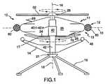
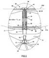
図1および図2に示す救命車両10は、空中飛行だけでなく地上における機能をも意図された、非常に平坦な球体または円板形状の船体などの本体を有する車両と言うことができる。車両10はまた、収縮または後退状態において水中で機能することも意図され、この場合は屋根付きボートとして水に浮かぶ船体として機能する。ここで使用する“本体”という用語は、車両の外殻全体を指し、車両の最も大きいまたは広い部分をなし船体中央部または中間点に配される外周安定部12より上に位置する上部分11と、前記外周安定部より下に位置する下部分13とからなる。下部分13の下側には、車両が水中にある時に水面下に位置することが意図された堅固な材料から製造される安定手段14が配されている。ここで強調しておくが、船体中央部に位置する外周安定部12は、水平軸15または水平面において車両の外周に延び、垂直軸16は、車両を囲み船体中央部に位置する安定部の幾何学的中心点において直交している。下側に位置する安定手段14は、円板状であって中空の円錐台形またはピラミッド型をなすバラストと言うことができ、幅広端が上側を向いており、底部外面に適合し前記底部に密着させることができる、逆すり鉢形状を有している。これは特に図2に明示されている。安定手段14の目的の一つは、バラストとして機能し水中において車両の横揺れを防ぐことであり、このため安定手段は水面下に配される。この安定部材により波の動きに対し充分な抗力が得られ、車両が“波乗り”することなく、いかなる海洋状況においても確実に安定した直立位置を保つことができる。船体中央部に位置する安定部12には、泳いでいる人がつかみ易いようハンドルを設けてもよく、また、車両が水中でなんらかの物体と衝突した際の衝撃吸収のために防舷材を設けてもよい。 The
車両の垂直軸16回りを回転可能で複数のブレード18を有するロータ17が、安定手段14が下部分13に接する後退位置にあるときに安定手段14により画定される区画内に配されている。このロータ17は主としてプロペラとして機能することが意図されるが、救命車両10が水中にあるときに揚力を得るための機能も有する。ロータ17は、回転軸16に対し主に直交する第1面P18内で周方向に互いに等間隔に配された4枚のロータブレード18を備える。 A
救命車両10の下方、より正確には安定手段14の下側には、上下動可能な3本の支持脚19が設けられている。図3にも示すように、前記支持脚19は、安定手段14の中心のフード型部材21の符号20において関節結合されており、支持脚が安定手段14の下向き面と平行に延びる図2に示す後退位置から、図1に示すように車両が支持脚上に支持される状態へ、ピストン・シリンダ構造22により3本同時に下降させることができる。 Three
上部分11および下部分13から形成される救命車両10の殻型本体の内部には強化壁および横壁が設けられている。さらに、救命車両10は、無線、レーダ反射装置、快適性に必要な構造、駆動モータ、救命具など、想定される全ての機材類を備えることが相応しく、これらは全て基本的に、適切な区画内(図面では不図示)に収納・配置される。下部分13内には内部床24が配され、比較的多数の人員を比較的快適かつ安全な状態で収容することが意図された乗員または船員室25の底を形成する。 A reinforcing wall and a lateral wall are provided inside the shell-type main body of the
上部分11の頂部および下部分13の底部に、出入り口26または昇降口が配される。出入り口26は内側と外側の双方から施錠・解錠できるよう構成され、基本的に航空機に用いられる従来の出入り口である。 At the top of the
救命車両10の製造に適した材料は、ガラス繊維強化合成プラスチック樹脂材であることが確認されている。通常は、ボート船体の建造に通常用いられる種類のガラス繊維または複合材である。代替材料としては、鋼材やアルミニウムなどの金属が挙げられる。船体は、乗員が水平方向に360°見回せるよう、色付きで透明のプラスチックから製造することが適している。車両回りを自由に見渡せることが望ましい理由は、本明細書で後ほど明らかとなる。出入り口26を見つけ易くするために、出入り口をより濃い色の透明材料から製造してもよい。 It has been confirmed that a material suitable for manufacturing the life-saving
主にリング状で内側に向いて座るよう背もたれが設けられたベンチが、乗員または船員室25内の下部分13の内面に接して配されている(図面では不図示)。車両周囲に水平軸15上に延びる安定部12は、その一部がリング状に回りを取りまく円筒などのように中空で浮き室を形成していてもよい。この浮き室を発泡プラスチックで充填してもよい。さらに、安定部12は、比較的厚い弾性材料で製造し、衝撃吸収材および強化・補強フランジの双方として機能するようにしてもよい。図1および図2に示すように垂直軸16上の最も上側に配される殻形状の上部円屋根28から、車両の効率性に関するさらなる要素が設けられる。また、詳しく図示はしていないが、例えば吸気管29および排気管30などの一つまたは複数の換気構造が上部円屋根28に配される。図3も参照のこと。 A bench, which is mainly ring-shaped and provided with a backrest so as to sit inward, is arranged in contact with the inner surface of the
上部分11および下部分13間の中央には、比較的大径を有し入れ子式に互いに挿入される断面円形の円筒チューブ40:1〜40:nから形成される内部円筒カバーとして設計された伸縮構造40が中心軸に沿って延びている。前記チューブは鋼材またはアルミニウムから製造することが好ましい。伸縮構造40は、車両が水中で浮遊中に安定させる装置を備え、また、換気用空気をカプセル内に通すための搬送路を形成する役割も担っている。車両の浮遊力を安定させる装置は、図1および図2に示すように円筒カバーの長さを望遠鏡のように変化させることができる一連のまたは複数の入れ子式円筒部材40:1〜40:nからなる。円筒部材40:1〜40:nは、それぞれの相対的軸移動を制限するためにカラーを備えていてもよい。救命車両10が水中浮遊中は、媒体内における自身の慣性力により、また、前記伸縮構造40の作用により安定手段14を車両から離れるよう下方に移動させることによってカプセルの重心を垂直方向の上または下方向に部分的に調節することにより、車両が部分的に安定化される。伸縮円筒部材は、注入口および排出口31、32を通し円筒部材に供給される液圧媒体により、互いに相対移動される。図3を参照のこと。 In the middle between the
図1〜図3に示すように、円筒部材群40:1〜40:nが後退位置から伸展位置まで移動すると、最も内側の円筒部材42の下向き自由端に装着された安定手段14が、本体から離れるよう下向きに駆動される。この結果、救命車両の重心もまた大幅に下方に移動する。安定手段14の自由端または外周回りには、これを囲む例えばエラストマーなどの弾性リング状円筒体の形でシール手段46が配され、これは、安定手段14が伸縮構造40により下部分13に接するよう後退した位置にある時にカプセルの下部分13と接して密閉および支持するよう意図されている。上記救命車両は収縮状態にある時、図2に示すように対称形状を有するため、船舶などから海中に向け簡単に発進させることができる。 As shown in FIGS. 1 to 3, when the cylindrical member groups 40: 1 to 40: n move from the retracted position to the extended position, the stabilizing means 14 attached to the lower free end of the innermost
危険区域と安全な場所との間を迅速かつ効率的に移動できるよう、救命車両10には、水中移動の可能性だけでなく飛行能力をも提供する駆動手段を設けることができるが、ここでは、従来の翼やその他の空気力学的固定付属物は存在しない。より正確には、この目的のために救命車両10は、救命車両10の上部分11に位置し垂直軸16と同軸に回転するロータ52が設けられている。このロータ52は車両10に揚力を発生させることが意図され、少なくとも車両が最大限載荷した状態で水中から車両を引き揚げるのに必要な揚力を発生させるよう設計されている。車両の頂部に位置するロータ52を以下では“第1ロータ”と称し、車両の底部に位置するロータ18を“第2ロータ”と称する。 In order to be able to move quickly and efficiently between dangerous areas and safe places, the life-saving
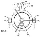
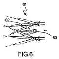
また、救命車両の駆動手段には、前進用に、船体の径方向に対向する側部に設けられ車両を推進するジェット流を発生させる一対のジェットモータ60を備える、迅速で効率的な水平退避手段が含まれている。図4および図5も参照のこと。図6から最も明らかに分かるように、各ジェットモータにはそれぞれの噴射流の噴出方向を調節するための手段61が設けられている。この手段は、図示しない制御・アクチュエータ手段の作用により水平軸63回りを回動可能な複数の制御フラップ62を備える。制御フラップ62が上向きに回動されると、噴出流は流れの主方向に対し斜め上に向かい、制御フラップが下向きに回動されると、噴出流は流れの主方向に対し斜め下に向かう。かくして制御フラップ62は車両10の高さ制御部として機能することができる。 Further, the life-saving vehicle driving means includes a pair of
再び図4および図5を参照すると、救命車両10には、上部分11から始まり車両の外周安定部12から径方向外向きに延びる、概して参照番号65で示す制御ユニットが設けられている。制御ユニット65は、左右舵66および一対の昇降舵67を有する安定板として設計された径方向に延びる本体を備える。救命車両10は、安定板の存在により、飛行中は流入気流に対し水平に飛ぶ傾向を有し、これにより操縦士は左右舵66により左右方向に救命車両10を有効に制御することができる。車両10の水平面に対する迎え角は、特に高速飛行において、昇降舵67によって有効に案内・制御することができる。 Referring again to FIGS. 4 and 5, the life-saving
以上述べたように、救命車両10の駆動手段は車両頂部に位置し垂直軸16回りに回転可能な第1ロータ52を備える。ロータ52は車両10の揚力を発生させることが意図されており、第2ロータ18とともに、少なくとも救命車両10を水中から持ち上げるのに必要な揚力を発生することができるよう選択および設計される。 As described above, the driving means of the
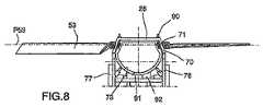
図8および図9を参照すると、第1ロータ52は車両の一部品である駆動手段により回転可能な一組のロータブレード53を備える。該駆動手段は、遊星歯車装置56および電子制御回路の形で、駆動モータ55および関連の変速機を有する推進チェーン54を備える。モータおよび推進チェーンは、船員室25の中央に位置し垂直方向に延びる伸縮構造40の底部に収納されている。車両内の下部に位置するため、モータ55および推進チェーン54はその重さにより車両の重心を低くすることに貢献し、特に車両が水中浮遊中はこれが利点となる。同様に、複数の燃料タンク58も救命車両の中央下部に組み入れられており、このタンクが一杯の時には特に効果的なバラストとして働く。 Referring to FIGS. 8 and 9, the
ロータ52は3枚のロータブレード53の第1群を支持し、これらは作動伸展位置において、回転軸16に基本的に直交、すなわち水平面15に基本的に平行な第1面P53内に延び、周方向に互いに等間隔で配されている。第1ロータのロータブレードはそれぞれが符号80にて車両の頂部に関節結合され、ピストン・シリンダ構造81により、同時に傾けて、上部分11の上向き面に向けて内方かつ下方の非作動位置に後退させることができる。図2も参照すると、前記後退位置においてブレード53は、車両の平坦球体または円板形状の上部分11と近接位置にあることが分かるはずである。これは、前述した支持脚19が車両10の下部分13と近接位置にあるのと同様で、救命車両は後退位置において、全体的に小さな寸法のコンパクトで堅牢な一体を形成し、外向き円弧状で同心の二個の分割体が合わさった形を主に表している。 The
図3および図8、図9に、ロータ52のロータブレード53の迎え角の制御・監視方法をより詳細に示す。迎え角を変化させることにより様々な度合いで救命車両10の揚力を発生させることができる。救命車両は、ロータ52により垂直上向きの大きな揚力を得ることができると同時に、わずかな力で水平面に平行に移動可能であることが理解できるはずである。駆動モータ55は概して一定速度で運転することが意図され、前記推進チェーン54の一部品である変速機を介してロータ52またはプロペラ17と動力伝達関係に自在に設置または離脱させることができる。変速機は関連のリングギアおよびピニオンと連動し、これと連動するピニオンはモータから延びる駆動軸(図面では図示せず)の一端に位置している。 3, 8, and 9 show the control / monitoring method of the angle of attack of the
図8、図9に最も明らかに示すように、ロータユニット52は、垂直軸16に直交して延びる軸54回りでロータブレード53を回転させる回転ユニット71の作用により、各ロータブレードの迎え角をそれぞれ独立して連続的に調節することを可能にする調節部70を備え、ブレードが一回転する全サイクルの間、適切な設定を保つようにする。回転ユニット71は歯車の作用によりロータブレードを回転させ、歯車はロータブレードの過回転を防ぐため、選択された数カ所において歯が欠けている。ロータブレード53とロータユニット52との間の接続部には圧縮空気ピストンが設けられ、ダンパとして働くバネにより囲まれている。調節部70は、機内に設けられた制御システムにより動作し、該制御システムによって、ロータが必要な揚力を発生させ、かつ所望の飛行指令に車両が従うよう、ロータスピードだけでなく迎え角も調節される。車両10の揚力は、モータ55の回転数を変更するより、ロータブレードの迎え角を増大することによってより効率的に増加させることができるのは言うまでもない。 As most clearly shown in FIGS. 8 and 9, the
各ロータブレード53の迎え角はそれぞれ独立して案内・監視可能であるだけでなく、水平面15に対する垂線16に対するロータユニット52全体の角度Aを案内・監視することもできる。このために、ロータユニットは、ホルダとして設計される軸受座73にボールのように自由に配されており、ロータブレード53およびこれらの迎え角設定用の調節部70を有する回転ユニット71を支えるロータユニットが、円弧面を自由に揺動し水平面15に対して異なる角度位置をとることができるようになっている。水平面に対するロータユニットの様々な角度位置Aは、ロータユニット52および固定軸受ハウジング77間で関節結合された複数の電動ピストン・シリンダ構造76により案内・監視することができる。 The angle of attack of each
参照番号90は、個々のロータブレード53を所望の角度位置に係止するための電子制御ロック手段を示す。参照番号91はガイドレール92沿いに移動可能な楔部材を示し、この楔部材によって、ボーリング玉のように支持されているロータユニット52を、水平面15に対する所定の角度位置にて楔効果により係止することができる。ロータユニット52全体を水平面15に対してある角度に固定することができる主要な利点の一つは、車両の進行方向を非常に迅速かつ効率的に設定できることである。
図4、図5に、車両本体の径方向に対向する側部に配され、水平方向の退避時に車両を駆動する一対の推進ユニット60をより詳しく示す。2個の推進ユニット60は船体中央部の、船体から径方向に一定距離突き出るように配され、水平面15と一致する共通の水平面内において外周安定部12に位置している。推進ユニット60は、車両内の制御手段により手動で操作可能なジェットモータを備える。推進ユニット60には、車両の燃料タンク58から延びる配管95を通じて燃料が供給される。 4 and 5 show in more detail a pair of
救命車両10は水平方向に移動(すなわち水平方向に退避)し、左右方向の制御および垂直方向の移動を効率的に行うため、各ジェットモータ60の噴出流の噴出方向を制御可能な前述の手段61を使用する。噴出流は、制御フラップ62を関連の水平軸63回りに回動することにより、流れの主方向に対し斜め上または斜め下に向かわせることができる。制御フラップ62を下方に回動させると噴出流は流れの主方向に対し斜め下に向かうため、これを使用することで、たとえば浮遊中に水上から車両を垂直上向きに向かわせる揚力を大幅に高めることができる。 The life-saving
以上から分かるように、ロータ52およびジェットモータ60の組み合わせによって、車両を水中位置から非常に迅速に、基本的に真上に向けて水面より上の位置に上昇させることができ、また、ジェットモータからの噴出流が真後ろを向くように制御フラップを再設定することで、災害区域から水平方向に退避する上で非常に素早く進路決定し前進することができる。 As can be seen from the above, the combination of the
図7の参照番号130は、操縦士用の制御位置131における、操舵輪を備える制御ユニットを示す。制御位置には車両の制御のためのコンピュータおよび類似の電子制御ユニットが設けられる。
本明細書で使用する“ロータ”という用語は、モータにより駆動される回転可能な部材を指し、本発明によれば、ロータだけでなくプロペラもこの用語に含まれる。さらに、第1ロータ52および第2ロータ17は関連の軸16、16’回りを機械的に同期させて反対方向に回転するよう配され、反対方向に基本的に同等のトルクを出現させることにより、本体が不要に自己回転することなく所望の安定性およびバランスを得るようにするとよい。 As used herein, the term “rotor” refers to a rotatable member driven by a motor, and according to the present invention, this term includes propellers as well as rotors. Furthermore, the
本発明は以上に述べ図面に示したものに限られず、添付の特許請求の範囲により定義される新規な概念の範囲内において様々に変更、改変が可能である。
The present invention is not limited to what has been described above and shown in the drawings, and various changes and modifications can be made within the scope of the novel concept defined by the appended claims.
Claims (10)
Translated fromJapanese車両の最も幅広部分または中心に沿う円筒部材として設計され車両が水中にある際にこれを安定させる浮き室を有する安定構造(12)と、該本体の中心に配され垂直方向に該本体を貫通し、入れ子式に互いに挿入される断面円形の円筒チューブ(40:1〜40:n)から形成される内部円筒カバーとして設計される伸縮構造(40)と、該下部分に配され、車両の垂直軸(16)から径方向に突出する基本的に円板形状のユニットを含み、伸縮構造(40)の作動により該下部分の下部から下方へ向けて垂直方向に移動可能な安定手段(14)とを備え、
空中だけでなく水中でも移動するために、車両が、
一方のロータ(52)が車両の上部分(11)から突出して配され、第2ロータ(17)が車両の下部分(13)から突出して配されることにより、第1ロータ(52)が第1のブレード面(P53)内に延びる一組のロータブレード(52)を備え、第2ロータ(17)が第2のブレード面(P18)内に延びる複数のロータブレード(18)を備える、第1および第2の軸(16、16’)回りをそれぞれ反対方向に回転するよう装着された第1および第2ロータ(52、17)と、
関連の変速機(54)とともに車両に支持され、前記第1および第2ロータ(52、17)をそれぞれ回転させて車両周囲の水または空気で形成される媒体内で垂直方向の揚力を発生させるためのモータ(55)と、
車両を水平方向に推進するために船体の径方向に対向する側部に装着された一対の推進ユニット(60)と、
車両の外周から径方向に突出して配され、通過する媒体流の作用により車両を操作するために左右舵(66)および昇降舵(67)が設けられた安定板(65)と、
を備えたことを特徴とする、救命車両(10)。A life-saving vehicle (10) designed as a hollow body such as a sphere or a disk-shaped hull basically flattened along a vertical axis (16) so as to have a maximum width in a horizontal plane (15), The main body is composed of an upper part (11) and a lower part (13), and defines a passenger compartment (25) therein,
A stable structure (12) designed as a cylindrical member along the widest part or center of the vehicle and having a floating chamber that stabilizes the vehicle when it is underwater, and the body is vertically centered and penetrates the body And a telescopic structure (40) designed as an inner cylindrical cover formed from cylindrical tubes (40: 1 to 40: n) having a circular cross section inserted into one another in a nested manner, and arranged in the lower part, Stabilization means (14) comprising a basically disk-shaped unit projecting radially from the vertical axis (16) and movable vertically downward from the lower part of the lower part by operation of the telescopic structure (40) )
In order to move not only in the air but also in the water,
One rotor (52) is arranged to protrude from the upper part (11) of the vehicle, and the second rotor (17) is arranged to protrude from the lower part (13) of the vehicle, whereby the first rotor (52) is arranged. A set of rotor blades (52) extending into the first blade surface (P53) and a second rotor (17) including a plurality of rotor blades (18) extending into the second blade surface (P18); First and second rotors (52, 17) mounted to rotate in opposite directions about first and second axes (16, 16 '), respectively;
Supported by a vehicle with an associated transmission (54), the first and second rotors (52, 17) are each rotated to generate vertical lift in a medium formed by water or air around the vehicle. A motor (55) for
A pair of propulsion units (60) mounted on the radially opposite sides of the hull to propel the vehicle horizontally;
A stabilizing plate (65) provided with a left and right rudder (66) and an elevator (67) for operating the vehicle by the action of a passing medium flow, projecting radially from the outer periphery of the vehicle;
A life-saving vehicle (10) characterized by comprising:
Applications Claiming Priority (3)
| Application Number | Priority Date | Filing Date | Title |
|---|---|---|---|
| SE1050584-0 | 2010-06-08 | ||
| SE1050584ASE535346C2 (en) | 2010-06-08 | 2010-06-08 | survival craft |
| PCT/SE2011/050696WO2011155892A1 (en) | 2010-06-08 | 2011-06-07 | Life-saving vehicle |
Publications (2)
| Publication Number | Publication Date |
|---|---|
| JP2013531578Atrue JP2013531578A (en) | 2013-08-08 |
| JP5807060B2 JP5807060B2 (en) | 2015-11-10 |
Family
ID=45098305
Family Applications (1)
| Application Number | Title | Priority Date | Filing Date |
|---|---|---|---|
| JP2013514136AExpired - Fee RelatedJP5807060B2 (en) | 2010-06-08 | 2011-06-07 | Life-saving vehicle |
Country Status (12)
| Country | Link |
|---|---|
| US (1) | US8919691B2 (en) |
| EP (1) | EP2580118A1 (en) |
| JP (1) | JP5807060B2 (en) |
| KR (1) | KR20130124937A (en) |
| CN (1) | CN103003148B (en) |
| AU (1) | AU2011262543B8 (en) |
| CA (1) | CA2802027A1 (en) |
| EA (1) | EA021815B1 (en) |
| MX (1) | MX2012014436A (en) |
| MY (1) | MY159133A (en) |
| SE (1) | SE535346C2 (en) |
| WO (1) | WO2011155892A1 (en) |
Cited By (4)
| Publication number | Priority date | Publication date | Assignee | Title |
|---|---|---|---|---|
| CN103640675A (en)* | 2013-12-18 | 2014-03-19 | 江苏科技大学 | Amphibious unmanned surface vehicle with three bodies |
| JP2018127216A (en)* | 2018-04-10 | 2018-08-16 | 株式会社0 | Rotorcraft |
| JP2018127218A (en)* | 2018-04-10 | 2018-08-16 | 株式会社0 | Rotary-wing airplane |
| JP2018127217A (en)* | 2018-04-10 | 2018-08-16 | 株式会社0 | Rotary-wing airplane |
Families Citing this family (32)
| Publication number | Priority date | Publication date | Assignee | Title |
|---|---|---|---|---|
| US9384668B2 (en) | 2012-05-09 | 2016-07-05 | Singularity University | Transportation using network of unmanned aerial vehicles |
| CA2997790C (en)* | 2013-05-15 | 2021-06-29 | Autel Robotics Usa Llc | Compact unmanned rotary aircraft |
| WO2014080387A2 (en)* | 2014-03-25 | 2014-05-30 | Alshdaifat, Wasfi | Rescue drone |
| CN103979107B (en)* | 2014-05-21 | 2016-01-20 | 北京理工大学 | A kind of folding rotor type unmanned plane |
| US10647413B2 (en)* | 2014-09-30 | 2020-05-12 | Sikorsky Aircraft Corporation | Enhanced engine load demand anticipation |
| US20170297605A1 (en)* | 2014-10-08 | 2017-10-19 | Aeromobil, S.R.O. | A directional control system for a hybrid air and ground transportation vehicle |
| US9855510B2 (en)* | 2014-11-14 | 2018-01-02 | Tang System | Disclub golf and phonefly: xPhone with SFDPCC and dual-phone-watch pair smart flying disc phone for cloud computation |
| KR101683610B1 (en)* | 2014-12-30 | 2016-12-07 | 박영찬 | Submarine and Flying Automobile |
| FR3032687B1 (en)* | 2015-02-16 | 2018-10-12 | Hutchinson | AERODYNE VTOL WITH SOUFFLANTE (S) AXIALE (S) CARRIER (S) |
| US10071800B2 (en)* | 2015-10-23 | 2018-09-11 | Jedidya L. Boros | Heavy Lift airborne transport device |
| EP3374263A4 (en)* | 2015-11-10 | 2019-05-08 | Matternet, Inc. | METHODS AND TRANSPORT SYSTEMS USING PILOT-FREE AIR VEHICLES |
| CN106741910A (en)* | 2016-12-28 | 2017-05-31 | 上海瞬动科技有限公司合肥分公司 | A kind of disc-shaped unmanned machine |
| US20200130825A1 (en)* | 2017-02-21 | 2020-04-30 | Prasad Muthukumar | Neutral axis duct with tandem telescopic thrust vectoring leading and trailing edge propellers for multi-mode spatial vehicle |
| CN106976563A (en)* | 2017-04-27 | 2017-07-25 | 峨眉山市博派乐无人机科技有限公司 | Pesticide spraying unmanned plane |
| RU2652476C1 (en)* | 2017-06-28 | 2018-04-26 | Федеральное государственное бюджетное образовательное учреждение высшего образования "Поволжский государственный технологический университет" | Amphibious transportation and technological platform |
| US9957045B1 (en)* | 2017-09-03 | 2018-05-01 | Brehnden Daly | Stackable drones |
| CN107719600A (en)* | 2017-10-21 | 2018-02-23 | 王凯盛 | A kind of rescue at sea equipment |
| CN107776848B (en)* | 2017-11-07 | 2019-04-02 | 常成 | A kind of overocean communications lifesaving appliance |
| CN108557075B (en)* | 2017-12-04 | 2020-07-31 | 中国人民解放军陆军工程大学 | Multi-drive VTOL fixed-wing UAV |
| US20190270516A1 (en)* | 2018-03-01 | 2019-09-05 | Bell Helicopter Textron Inc. | Propulsion Systems for Rotorcraft |
| CN109760830B (en)* | 2019-03-20 | 2020-10-20 | 山东天衢精密工业有限公司 | Environment surveying is with three leg module combination formula rotor unmanned aerial vehicle that prop |
| US11718396B2 (en)* | 2019-06-12 | 2023-08-08 | Textron Innovations Inc. | Active sail blade |
| CN110356548A (en)* | 2019-08-07 | 2019-10-22 | 北京凌天世纪控股股份有限公司 | Explosion-proof flying robot |
| EP4592189A3 (en)* | 2019-10-09 | 2025-09-03 | Kitty Hawk Corporation | Hybrid power systems for different modes of flight |
| US11106221B1 (en)* | 2019-11-25 | 2021-08-31 | Kitty Hawk Corporation | Multicopter with self-adjusting rotors |
| CN112660334A (en)* | 2020-01-09 | 2021-04-16 | 广州船舶及海洋工程设计研究院(中国船舶工业集团公司第六0五研究院) | Rescue device |
| US11851178B2 (en)* | 2020-02-14 | 2023-12-26 | The Aerospace Corporation | Long range endurance aero platform system |
| US10926654B1 (en) | 2020-03-31 | 2021-02-23 | Kitty Hawk Corporation | Electric vertical take-off and landing vehicle with wind turbine |
| US10913547B1 (en) | 2020-03-31 | 2021-02-09 | Kitty Hawk Corporation | Charging station for self-balancing multicopter |
| CN113120232B (en)* | 2021-04-26 | 2022-02-01 | 徐倩倩 | Unmanned aerial vehicle capable of realizing attitude adjustment by folding rotating propellers |
| CN114465065B (en)* | 2022-01-06 | 2023-11-03 | 广东汇天航空航天科技有限公司 | Aircraft main shaft slip ring device, aircraft rotor system and aircraft |
| US12145753B2 (en)* | 2022-08-09 | 2024-11-19 | Pete Bitar | Compact and lightweight drone delivery device called an ArcSpear electric jet drone system having an electric ducted air propulsion system and being relatively difficult to track in flight |
Citations (8)
| Publication number | Priority date | Publication date | Assignee | Title |
|---|---|---|---|---|
| US3176644A (en)* | 1963-06-26 | 1965-04-06 | Movible Offshore Inc | Retractable dampener for vessels |
| US3673974A (en)* | 1970-03-17 | 1972-07-04 | Dresser Ind | Method and mobile marine platform apparatus having floating submerged mat stabilization |
| JPH03121996A (en)* | 1989-09-22 | 1991-05-23 | Piasecki Aircraft Corp | Tail device for rotor aircraft |
| JPH08150818A (en)* | 1994-11-29 | 1996-06-11 | Rokuro Hosoda | Multifunction helicopter |
| US5722797A (en)* | 1996-02-21 | 1998-03-03 | Deep Oil Technology, Inc. | Floating caisson for offshore production and drilling |
| JP2006017149A (en)* | 2004-06-30 | 2006-01-19 | Mitsubishi Heavy Ind Ltd | Power transmission device for flying object |
| CA2546207A1 (en)* | 2006-05-08 | 2007-11-08 | Guangming Minc He | Flying vehicle |
| CN101327720A (en)* | 2008-05-30 | 2008-12-24 | 武汉舒居科技有限公司 | Triphibian |
Family Cites Families (27)
| Publication number | Priority date | Publication date | Assignee | Title |
|---|---|---|---|---|
| DE406441C (en)* | 1924-11-22 | Raul Pateras Pescara | Helicopter | |
| US1884848A (en)* | 1925-12-12 | 1932-10-25 | Autogiro Co Of America | Aircraft device |
| US1701762A (en)* | 1926-04-14 | 1929-02-12 | Harold F Pitcairn | Helicopter-control mechanism |
| NO751010L (en)* | 1975-03-24 | 1976-09-27 | Anker Holth Leif | |
| US4023751A (en)* | 1976-07-28 | 1977-05-17 | Richard Walter A | Flying ship |
| US4071206A (en)* | 1976-09-20 | 1978-01-31 | Aerospace General Co. | Portable helicopter |
| SU990582A1 (en)* | 1981-08-17 | 1983-01-23 | Институт гидромеханики АН УССР | Semisubmerged offshore drilling rig |
| FR2563803A1 (en)* | 1984-05-03 | 1985-11-08 | Demereau Jean | Telescopic underwater system for stabilising boats |
| US5035377A (en)* | 1985-02-28 | 1991-07-30 | Technolizenz Establishment | Free standing or aircraft lift generator |
| US4796836A (en)* | 1985-02-28 | 1989-01-10 | Dieter Schatzmayr | Lifting engine for VTOL aircrafts |
| AU2537792A (en)* | 1991-09-25 | 1993-04-01 | Jason Bruce Steward | Peripherly powered axial water jet motor |
| US5344100A (en)* | 1993-02-17 | 1994-09-06 | Allan Jaikaran | Vertical lift aircraft |
| FR2724905B1 (en)* | 1994-12-05 | 1997-06-20 | Demereau Jean Maurice | LIGHT SUBMARINE VESSEL STABILIZATION SYSTEM |
| US5653404A (en)* | 1995-04-17 | 1997-08-05 | Ploshkin; Gennady | Disc-shaped submersible aircraft |
| US6179247B1 (en)* | 1999-02-09 | 2001-01-30 | Karl F. Milde, Jr. | Personal air transport |
| AU7003700A (en)* | 1999-11-29 | 2001-06-12 | Natural Colour Kari Kirjavainen Oy | Aircraft rotor and aircraft |
| CN1342589A (en)* | 2000-09-13 | 2002-04-03 | 赵翼华 | Flying apparatus |
| JP2003104297A (en)* | 2001-09-30 | 2003-04-09 | Akio Tanaka | Flying, traveling, and navigating craft |
| RU2219097C2 (en)* | 2001-12-24 | 2003-12-20 | Никитин Андрей Андреевич | Floating and flying rescue facility for submariners |
| US7032861B2 (en)* | 2002-01-07 | 2006-04-25 | Sanders Jr John K | Quiet vertical takeoff and landing aircraft using ducted, magnetic induction air-impeller rotors |
| US6834829B2 (en)* | 2003-01-02 | 2004-12-28 | Percy E. Dunagin, Jr. | Vertical lift aircraft having an enclosed rotary wing |
| US6883750B2 (en)* | 2003-07-16 | 2005-04-26 | Sikorsky Aircraft Corporation | Split torque gearbox with pivoted engine support |
| CN100503365C (en)* | 2003-12-30 | 2009-06-24 | 何主能 | Coaxial unmanned lifting helicopter |
| US7802755B2 (en)* | 2004-03-10 | 2010-09-28 | Poltorak Alexander I | Rotating wing aircraft with tip-driven rotor and rotor guide-ring |
| US7873444B1 (en)* | 2007-02-08 | 2011-01-18 | Lockheed Martin Corporation | Controlling movement of an unmanned vehicle |
| CN101618758A (en)* | 2009-03-11 | 2010-01-06 | 黄灿荣 | Wind energy and solar energy power generation sea-air electric lifeboat |
| US8256705B2 (en)* | 2009-11-04 | 2012-09-04 | Raytheon Company | Torque production vehicle and method |
- 2010
- 2010-06-08SESE1050584Apatent/SE535346C2/ennot_activeIP Right Cessation
- 2011
- 2011-06-07MXMX2012014436Apatent/MX2012014436A/enactiveIP Right Grant
- 2011-06-07CACA2802027Apatent/CA2802027A1/ennot_activeAbandoned
- 2011-06-07MYMYPI2012005340Apatent/MY159133A/enunknown
- 2011-06-07CNCN201180034239.5Apatent/CN103003148B/ennot_activeExpired - Fee Related
- 2011-06-07AUAU2011262543Apatent/AU2011262543B8/ennot_activeCeased
- 2011-06-07KRKR1020137000555Apatent/KR20130124937A/ennot_activeCeased
- 2011-06-07JPJP2013514136Apatent/JP5807060B2/ennot_activeExpired - Fee Related
- 2011-06-07EAEA201390002Apatent/EA021815B1/ennot_activeIP Right Cessation
- 2011-06-07USUS13/702,995patent/US8919691B2/ennot_activeExpired - Fee Related
- 2011-06-07EPEP11792745.9Apatent/EP2580118A1/ennot_activeWithdrawn
- 2011-06-07WOPCT/SE2011/050696patent/WO2011155892A1/enactiveApplication Filing
Patent Citations (8)
| Publication number | Priority date | Publication date | Assignee | Title |
|---|---|---|---|---|
| US3176644A (en)* | 1963-06-26 | 1965-04-06 | Movible Offshore Inc | Retractable dampener for vessels |
| US3673974A (en)* | 1970-03-17 | 1972-07-04 | Dresser Ind | Method and mobile marine platform apparatus having floating submerged mat stabilization |
| JPH03121996A (en)* | 1989-09-22 | 1991-05-23 | Piasecki Aircraft Corp | Tail device for rotor aircraft |
| JPH08150818A (en)* | 1994-11-29 | 1996-06-11 | Rokuro Hosoda | Multifunction helicopter |
| US5722797A (en)* | 1996-02-21 | 1998-03-03 | Deep Oil Technology, Inc. | Floating caisson for offshore production and drilling |
| JP2006017149A (en)* | 2004-06-30 | 2006-01-19 | Mitsubishi Heavy Ind Ltd | Power transmission device for flying object |
| CA2546207A1 (en)* | 2006-05-08 | 2007-11-08 | Guangming Minc He | Flying vehicle |
| CN101327720A (en)* | 2008-05-30 | 2008-12-24 | 武汉舒居科技有限公司 | Triphibian |
Cited By (4)
| Publication number | Priority date | Publication date | Assignee | Title |
|---|---|---|---|---|
| CN103640675A (en)* | 2013-12-18 | 2014-03-19 | 江苏科技大学 | Amphibious unmanned surface vehicle with three bodies |
| JP2018127216A (en)* | 2018-04-10 | 2018-08-16 | 株式会社0 | Rotorcraft |
| JP2018127218A (en)* | 2018-04-10 | 2018-08-16 | 株式会社0 | Rotary-wing airplane |
| JP2018127217A (en)* | 2018-04-10 | 2018-08-16 | 株式会社0 | Rotary-wing airplane |
Also Published As
| Publication number | Publication date |
|---|---|
| EA021815B1 (en) | 2015-09-30 |
| EP2580118A1 (en) | 2013-04-17 |
| SE1050584A1 (en) | 2011-12-09 |
| JP5807060B2 (en) | 2015-11-10 |
| SE535346C2 (en) | 2012-07-03 |
| AU2011262543B2 (en) | 2016-03-31 |
| WO2011155892A1 (en) | 2011-12-15 |
| AU2011262543B8 (en) | 2016-04-07 |
| CA2802027A1 (en) | 2011-12-15 |
| US20130153706A1 (en) | 2013-06-20 |
| CN103003148B (en) | 2015-06-17 |
| EA201390002A1 (en) | 2013-06-28 |
| CN103003148A (en) | 2013-03-27 |
| AU2011262543A1 (en) | 2013-01-24 |
| MX2012014436A (en) | 2013-03-18 |
| US8919691B2 (en) | 2014-12-30 |
| MY159133A (en) | 2016-12-15 |
| KR20130124937A (en) | 2013-11-15 |
| AU2011262543A8 (en) | 2016-04-07 |
Similar Documents
| Publication | Publication Date | Title |
|---|---|---|
| JP5807060B2 (en) | Life-saving vehicle | |
| JP4223921B2 (en) | Vertical take-off and landing flight device | |
| KR101269273B1 (en) | Wireless Control Boat for Saving Life | |
| JP5875093B1 (en) | Levitation aircraft | |
| US4778128A (en) | Flying disc aircraft | |
| ES2799908T3 (en) | Unmanned aerial and underwater vehicle | |
| JP2014240242A (en) | Vertical take-off and landing flight vehicle | |
| CN107933914B (en) | Water-air amphibious sightseeing electric rotor aircraft | |
| US20110198438A1 (en) | Propulsion and steering system for an airship | |
| CN109562825B (en) | Multi-rotor aircraft with wide-span rotor configuration | |
| CA2914287A1 (en) | Aircraft with rotating outer shells | |
| CA2693672A1 (en) | Propulsion and steering system for an airship | |
| US7997059B1 (en) | Propulsion system | |
| JP3774764B2 (en) | Manned airship | |
| JP2010042792A (en) | Multifunctional airplane | |
| KR20230103016A (en) | Hover Craft with Dron | |
| JP7526433B1 (en) | Land, sea and air vehicles | |
| JP2019189194A (en) | Flying object | |
| WO2021225654A2 (en) | Amphibious aircraft taxiing and docking systems | |
| JPH0463800A (en) | Helicopter | |
| BRPI1003295A2 (en) | vehicle with circular propeller | |
| ITME940005A1 (en) | DISC ULTRALIGHT JETT | |
| PL212678B1 (en) | Hovercraft |
Legal Events
| Date | Code | Title | Description |
|---|---|---|---|
| A521 | Request for written amendment filed | Free format text:JAPANESE INTERMEDIATE CODE: A821 Effective date:20130412 | |
| A521 | Request for written amendment filed | Free format text:JAPANESE INTERMEDIATE CODE: A523 Effective date:20140514 | |
| A621 | Written request for application examination | Free format text:JAPANESE INTERMEDIATE CODE: A621 Effective date:20140514 | |
| A977 | Report on retrieval | Free format text:JAPANESE INTERMEDIATE CODE: A971007 Effective date:20150224 | |
| A131 | Notification of reasons for refusal | Free format text:JAPANESE INTERMEDIATE CODE: A131 Effective date:20150227 | |
| A521 | Request for written amendment filed | Free format text:JAPANESE INTERMEDIATE CODE: A523 Effective date:20150501 | |
| TRDD | Decision of grant or rejection written | ||
| A01 | Written decision to grant a patent or to grant a registration (utility model) | Free format text:JAPANESE INTERMEDIATE CODE: A01 Effective date:20150812 | |
| A61 | First payment of annual fees (during grant procedure) | Free format text:JAPANESE INTERMEDIATE CODE: A61 Effective date:20150907 | |
| R150 | Certificate of patent or registration of utility model | Ref document number:5807060 Country of ref document:JP Free format text:JAPANESE INTERMEDIATE CODE: R150 | |
| LAPS | Cancellation because of no payment of annual fees |