JP2013531537A - Dual optical path prism and camera in a minimally invasive surgical system - Google Patents
Dual optical path prism and camera in a minimally invasive surgical systemDownload PDFInfo
- Publication number
- JP2013531537A JP2013531537AJP2013518486AJP2013518486AJP2013531537AJP 2013531537 AJP2013531537 AJP 2013531537AJP 2013518486 AJP2013518486 AJP 2013518486AJP 2013518486 AJP2013518486 AJP 2013518486AJP 2013531537 AJP2013531537 AJP 2013531537A
- Authority
- JP
- Japan
- Prior art keywords
- light
- visible
- lens
- image
- invisible
- Prior art date
- Legal status (The legal status is an assumption and is not a legal conclusion. Google has not performed a legal analysis and makes no representation as to the accuracy of the status listed.)
- Granted
Links
Images


Classifications
- A—HUMAN NECESSITIES
- A61—MEDICAL OR VETERINARY SCIENCE; HYGIENE
- A61B—DIAGNOSIS; SURGERY; IDENTIFICATION
- A61B1/00—Instruments for performing medical examinations of the interior of cavities or tubes of the body by visual or photographical inspection, e.g. endoscopes; Illuminating arrangements therefor
- A61B1/04—Instruments for performing medical examinations of the interior of cavities or tubes of the body by visual or photographical inspection, e.g. endoscopes; Illuminating arrangements therefor combined with photographic or television appliances
- A61B1/05—Instruments for performing medical examinations of the interior of cavities or tubes of the body by visual or photographical inspection, e.g. endoscopes; Illuminating arrangements therefor combined with photographic or television appliances characterised by the image sensor, e.g. camera, being in the distal end portion
- A—HUMAN NECESSITIES
- A61—MEDICAL OR VETERINARY SCIENCE; HYGIENE
- A61B—DIAGNOSIS; SURGERY; IDENTIFICATION
- A61B1/00—Instruments for performing medical examinations of the interior of cavities or tubes of the body by visual or photographical inspection, e.g. endoscopes; Illuminating arrangements therefor
- A61B1/00163—Optical arrangements
- A61B1/00188—Optical arrangements with focusing or zooming features
- A—HUMAN NECESSITIES
- A61—MEDICAL OR VETERINARY SCIENCE; HYGIENE
- A61B—DIAGNOSIS; SURGERY; IDENTIFICATION
- A61B1/00—Instruments for performing medical examinations of the interior of cavities or tubes of the body by visual or photographical inspection, e.g. endoscopes; Illuminating arrangements therefor
- A61B1/00163—Optical arrangements
- A61B1/00193—Optical arrangements adapted for stereoscopic vision
- A—HUMAN NECESSITIES
- A61—MEDICAL OR VETERINARY SCIENCE; HYGIENE
- A61B—DIAGNOSIS; SURGERY; IDENTIFICATION
- A61B1/00—Instruments for performing medical examinations of the interior of cavities or tubes of the body by visual or photographical inspection, e.g. endoscopes; Illuminating arrangements therefor
- A61B1/04—Instruments for performing medical examinations of the interior of cavities or tubes of the body by visual or photographical inspection, e.g. endoscopes; Illuminating arrangements therefor combined with photographic or television appliances
- A61B1/055—Instruments for performing medical examinations of the interior of cavities or tubes of the body by visual or photographical inspection, e.g. endoscopes; Illuminating arrangements therefor combined with photographic or television appliances having rod-lens arrangements
- G—PHYSICS
- G02—OPTICS
- G02B—OPTICAL ELEMENTS, SYSTEMS OR APPARATUS
- G02B13/00—Optical objectives specially designed for the purposes specified below
- G02B13/14—Optical objectives specially designed for the purposes specified below for use with infrared or ultraviolet radiation
- G02B13/146—Optical objectives specially designed for the purposes specified below for use with infrared or ultraviolet radiation with corrections for use in multiple wavelength bands, such as infrared and visible light, e.g. FLIR systems
- G—PHYSICS
- G02—OPTICS
- G02B—OPTICAL ELEMENTS, SYSTEMS OR APPARATUS
- G02B23/00—Telescopes, e.g. binoculars; Periscopes; Instruments for viewing the inside of hollow bodies; Viewfinders; Optical aiming or sighting devices
- G02B23/24—Instruments or systems for viewing the inside of hollow bodies, e.g. fibrescopes
- G02B23/2407—Optical details
- G02B23/2453—Optical details of the proximal end
- G—PHYSICS
- G02—OPTICS
- G02B—OPTICAL ELEMENTS, SYSTEMS OR APPARATUS
- G02B27/00—Optical systems or apparatus not provided for by any of the groups G02B1/00 - G02B26/00, G02B30/00
- G02B27/0025—Optical systems or apparatus not provided for by any of the groups G02B1/00 - G02B26/00, G02B30/00 for optical correction, e.g. distorsion, aberration
- G—PHYSICS
- G02—OPTICS
- G02B—OPTICAL ELEMENTS, SYSTEMS OR APPARATUS
- G02B27/00—Optical systems or apparatus not provided for by any of the groups G02B1/00 - G02B26/00, G02B30/00
- G02B27/10—Beam splitting or combining systems
- G02B27/14—Beam splitting or combining systems operating by reflection only
- G02B27/141—Beam splitting or combining systems operating by reflection only using dichroic mirrors
Landscapes
- Physics & Mathematics (AREA)
- Health & Medical Sciences (AREA)
- Life Sciences & Earth Sciences (AREA)
- Optics & Photonics (AREA)
- Surgery (AREA)
- General Physics & Mathematics (AREA)
- Medical Informatics (AREA)
- Veterinary Medicine (AREA)
- Pathology (AREA)
- Engineering & Computer Science (AREA)
- Biomedical Technology (AREA)
- Heart & Thoracic Surgery (AREA)
- Nuclear Medicine, Radiotherapy & Molecular Imaging (AREA)
- Molecular Biology (AREA)
- Animal Behavior & Ethology (AREA)
- General Health & Medical Sciences (AREA)
- Public Health (AREA)
- Radiology & Medical Imaging (AREA)
- Biophysics (AREA)
- Astronomy & Astrophysics (AREA)
- Toxicology (AREA)
- Endoscopes (AREA)
- Instruments For Viewing The Inside Of Hollow Bodies (AREA)
- Optical Elements Other Than Lenses (AREA)
- Stereoscopic And Panoramic Photography (AREA)
- Lenses (AREA)
- Camera Bodies And Camera Details Or Accessories (AREA)
Abstract
Translated fromJapaneseDescription
Translated fromJapanese本発明の態様は、内視鏡イメージングに関し、より詳細には、可視光の像と近赤外光又は紫外光の像の同時集束に関する。 Aspects of the present invention relate to endoscopic imaging, and more particularly to simultaneous focusing of a visible light image and a near infrared or ultraviolet light image.
インテューティブ・サージカル社(Intuitive Surgical)社によって市販されているダビンチ(登録商標)外科手術システムは、多くの利点−たとえば人体への外傷の低減、迅速な回復、及び病院での滞在を短期間にする−を与える低侵襲遠隔操作手術システムである。ダビンチ外科手術システムの一の重要な構成要素は、外科医が立体像を見ることができるように、可視像の2チャネル(つまり左と右)ビデオ取り込み及び表示を行うことである。 The Da Vinci (R) surgical system marketed by Intuitive Surgical has many advantages-for example, reduced trauma to the human body, rapid recovery, and short hospital stay This is a minimally invasive teleoperated surgical system. One important component of the Da Vinci surgical system is the two-channel (ie, left and right) video capture and display of the visible image so that the surgeon can see the stereoscopic image.
そのような電子立体像イメージングシステムは、高解像度ビデオ像を外科医へ出力し、かつ、その外科医が、向上した精度での処置を行うだけではなく特定の細胞組織の型や特性を特定できるようにする「拡大」像を供することを可能にする。しかし典型的な手術分野では、ある細胞組織の型は特定が困難である。あるいは関心細胞組織の少なくとも一部は他の細胞組織によって見えにくくなることがある。このため外科処置は複雑になる。 Such an electronic stereoscopic imaging system outputs a high-resolution video image to the surgeon and allows the surgeon not only to perform the procedure with improved accuracy but also to identify the type and characteristics of a particular cellular tissue. It makes it possible to provide an “enlarged” image. However, in typical surgical fields, certain cell tissue types are difficult to identify. Alternatively, at least a part of the cell tissue of interest may be difficult to see by other cell tissues. This complicates the surgical procedure.
用途によっては、近赤外スペクトルでの蛍光像及び反射白色光像が、低侵襲手術において用いられる。しかし近赤外蛍光像の後焦点距離は、反射白色光像の後焦点距離とは異なる。よって一の動作モードから他の動作モードへ切り換えるときに、焦点の調節が必要になる。近赤外蛍光像と反射白色光像の両方が同時に見られるとき、内視鏡内の典型的な光学系とカメラは、2つの像を同時に集束させない。同様の状況は、紫外スペクトルにおいても起こりうる。 Depending on the application, fluorescent images and reflected white light images in the near-infrared spectrum are used in minimally invasive surgery. However, the back focal length of the near-infrared fluorescent image is different from the back focal length of the reflected white light image. Therefore, it is necessary to adjust the focus when switching from one operation mode to another operation mode. When both a near-infrared fluorescent image and a reflected white light image are viewed simultaneously, the typical optical system and camera in the endoscope do not focus the two images simultaneously. A similar situation can occur in the ultraviolet spectrum.
各異なる波長の像の焦点面における差異に対する一の解決法が特許文献1に記載されている。この手法は、それぞれ屈折率の異なる複数の部材を含むプリズムを利用する。二色性コーティングが、前記部材間の対角面上に設けられる。その際その対角面の半分は、可視光を透過して近赤外光を反射する短光路コーティングによりコーティングされる。その対角面のうち前記短光路コーティングによりコーティングされない部分は、近赤外光を透過して可視光を反射する長光路コーティングによりコーティングされる。 One solution to the difference in the focal plane of images of different wavelengths is described in US Pat. This method uses a prism including a plurality of members each having a different refractive index. A dichroic coating is provided on the diagonal between the members. The half of the diagonal surface is then coated with a short path coating that transmits visible light and reflects near infrared light. The portion of the diagonal surface that is not coated with the short optical path coating is coated with a long optical path coating that transmits near infrared light and reflects visible light.
この手法は、焦点の差異が小さい場合には機能する。しかしこの手法は、焦点の差異が大きな場合には実用的ではない。その理由は、必要とされるプリズムのサイズが大きくなりすぎるからである。この手法はまた物理的に大きなカメラを必要とする。結像光路がある程度横方向にずれる結果、カメラ組立体が大きくなってしまうからである。この手法ではまた、その設計を満足するように、厳密に「正しい」屈折率及びアッベ数を有する2つの材料を見つけることが必要となる。適切な材料の数は限られている。そのため解決はし得ない。この手法はまた、より一般的な光学収差をも補正することができない。 This approach works when the focus difference is small. However, this method is not practical when the focus difference is large. The reason is that the required prism size becomes too large. This approach also requires a physically large camera. This is because the image forming optical path is shifted to some extent in the lateral direction, resulting in a large camera assembly. This approach also requires finding two materials with strictly “correct” refractive indices and Abbe numbers to satisfy the design. The number of suitable materials is limited. Therefore, it cannot be solved. This approach also cannot correct more general optical aberrations.
一の態様では、内視鏡カメラは、可視像と非可視像のうちの一を集束させるように構成された後、前記可視像と非可視像を適切に集束させる。一の態様では、前記カメラは、内部にレンズを有するプリズム素子を含む。前記レンズは、近赤外における関心波長範囲にて前記内視鏡の光学系により生成される長手(軸)方向の色を補正する。それにより前記可視像と近赤外像の両方が、前記カメラ内のイメージセンサで集束する。前記カメラ内部の像取り込み装置と集束光学系は、変化しないように維持されて良い。 In one aspect, the endoscopic camera is configured to focus one of the visible image and the invisible image, and then appropriately focuses the visible image and the invisible image. In one aspect, the camera includes a prism element having a lens therein. The lens corrects the color in the longitudinal (axial) direction generated by the optical system of the endoscope in the wavelength range of interest in the near infrared. Thereby, both the visible image and the near-infrared image are focused by the image sensor in the camera. The image capturing device and the focusing optical system inside the camera may be kept unchanged.
本明細書において用いられる蛍光という語は、近赤外スペクトルにおいて放出された光であるが、これは単なる例示であり、限定を意図するものではない。本開示を考慮すると、近赤外スペクトル又は紫外スペクトルのいずれかにおいて放出される蛍光が処理されて良い。 As used herein, the term fluorescence is light emitted in the near infrared spectrum, but this is merely illustrative and not intended to be limiting. In view of the present disclosure, fluorescence emitted in either the near infrared spectrum or the ultraviolet spectrum may be processed.
近赤外において良好な性能を有するように意図して設計されない光学系による近赤外イメージングは、軸方向の色収差と他の光学収差の両方を示す傾向にある。前記プリズム素子のレンズは、前記他の光学収差をも緩和しうる。 Near-infrared imaging with optical systems that are not designed to have good performance in the near infrared tends to exhibit both axial chromatic and other optical aberrations. The lens of the prism element can alleviate the other optical aberrations.
一の態様では、前記プリズム素子内のレンズは可変である。それにより前記カメラは、様々な光学特性を有する内視鏡と併用されうる。他の態様では、前記レンズは、前記プリズム素子内の2つの隣接するプリズムの面内に形成される。あるいはその代わりに曲面が、他の光路中での前記プリズムの斜面上であっても良い。さらに他の態様では、前記レンズの代わりに回折素子が用いられる。 In one aspect, the lens in the prism element is variable. Thereby, the camera can be used in combination with an endoscope having various optical characteristics. In another aspect, the lens is formed in the plane of two adjacent prisms in the prism element. Alternatively, the curved surface may be on the slope of the prism in another optical path. In yet another aspect, a diffractive element is used instead of the lens.
他の態様では、一例として、前記非可視光は蛍光で、かつ、前記可視光は白色光の可視成分を含む。さらに他の態様では、前記蛍光は近赤外蛍光である。 In another aspect, by way of example, the invisible light is fluorescent and the visible light includes a visible component of white light. In yet another aspect, the fluorescence is near infrared fluorescence.
方法は、低侵襲手術装置から可視光と非可視光を含む光を受け取る手順を有する。前記可視光は前記非可視光から分離される。 The method includes a procedure for receiving light, including visible light and invisible light, from a minimally invasive surgical device. The visible light is separated from the invisible light.
当該方法では、前記可視光と非可視光のうちの一はレンズを通過する。前記レンズは、前記可視光と非可視光のうちの一から生成される像の焦点を補正する。それにより前記可視光の像と前記非可視光の像を生成する光学系の(結像される波長で測定された)全体の焦点長は略同一となる。その結果、前記可視光と非可視光から生成される像の焦点は妥当なものとなる。 In the method, one of the visible light and invisible light passes through a lens. The lens corrects a focus of an image generated from one of the visible light and invisible light. Thereby, the entire focal length (measured at the imaged wavelength) of the optical system that generates the visible light image and the invisible light image is substantially the same. As a result, the focal point of the image generated from the visible light and the invisible light becomes reasonable.
また当該方法では、前記レンズからの前記可視光と非可視光のうちの一は、前記レンズからの前記可視光と非可視光のうちの他と再結合する。前記の再結合した可視光と非可視光は集束する。 In the method, one of the visible light and invisible light from the lens is recombined with the other of the visible light and invisible light from the lens. The recombined visible light and invisible light are focused.
本発明の他の態様では、前記可視光と非可視光のうちの一はレンズを通過する。前記レンズは、前記可視光と非可視光のうちの一から生成される像の焦点を補正する。それにより前記像の焦点は、前記可視光と非可視光のうちの他から生成される像の焦点と略同一となる。前記レンズからの前記可視光と非可視光のうちの一は、前記可視光と非可視光のうちの他と再結合する。 In another aspect of the invention, one of the visible light and invisible light passes through a lens. The lens corrects a focus of an image generated from one of the visible light and invisible light. Thereby, the focal point of the image becomes substantially the same as the focal point of the image generated from the other of the visible light and the invisible light. One of the visible and invisible light from the lens recombines with the other of the visible and invisible light.
本発明のさらに他の態様では、前記可視光と非可視光のうちの一はレンズを通過する。前記レンズは、前記可視光と非可視光のうちの一から生成される像の収差を修正する。それにより前記像の知覚される焦点は、前記可視光と非可視光のうちの他から生成される像の焦点と略同一となる。前記レンズからの前記可視光と非可視光のうちの一は、前記可視光と非可視光のうちの他と再結合する。 In still another aspect of the invention, one of the visible light and invisible light passes through a lens. The lens corrects an aberration of an image generated from one of the visible light and invisible light. Thereby, the perceived focus of the image is substantially the same as the focus of the image generated from the other of the visible light and the invisible light. One of the visible and invisible light from the lens recombines with the other of the visible and invisible light.
低侵襲手術システムは、内部にレンズを有するプリズム素子を含むカメラを備える。一の態様では、前記レンズの代わりに回折素子が用いられる。前記レンズは、前記可視光と非可視光のうちの一から生成される像の焦点を補正する。それにより前記可視光と非可視光のうちの一から生成される像の焦点は、前記プリズム素子を通過する前記可視光と非可視光のうちの他から生成される他の像の焦点と略同一となる。 The minimally invasive surgical system includes a camera including a prism element having a lens therein. In one embodiment, a diffractive element is used instead of the lens. The lens corrects a focus of an image generated from one of the visible light and invisible light. Thereby, the focal point of the image generated from one of the visible light and invisible light is substantially the same as the focal point of the other image generated from the other of the visible light and invisible light passing through the prism element. It will be the same.
前記プリズム素子は、通過と反射を行うコーティング有する第1表面を含む。前記コーティングは、前記可視光と非可視光のうちの他を通過させ、かつ、前記可視光と非可視光のうちの一を反射させる。 The prism element includes a first surface having a coating that passes and reflects. The coating passes the other of the visible light and invisible light and reflects one of the visible light and invisible light.
前記プリズム素子はまた第2表面をも含む。前記第2表面は、前記第1表面とは反対でかつ前記第1表面から離れていて、反射コーティングを有する。 The prism element also includes a second surface. The second surface has a reflective coating opposite to the first surface and spaced from the first surface.
前記プリズム素子は複数のプリズムを有する。一の態様では、前記レンズは、前記複数のプリズムのうちの2つの隣接するプリズムの面内に形成される。 The prism element has a plurality of prisms. In one aspect, the lens is formed in the plane of two adjacent prisms of the plurality of prisms.
さらに他の態様では、低侵襲手術システムは、結像面を有するカメラと、焦点補正組立体を含む。前記焦点補正組立体は、第1光路と、レンズを有する第2光路と、共通の開始位置と、共通の終了位置を含む。前記第2光路は前記第1光路よりも長い。 In yet another aspect, a minimally invasive surgical system includes a camera having an imaging plane and a focus correction assembly. The focus correction assembly includes a first optical path, a second optical path having a lens, a common start position, and a common end position. The second optical path is longer than the first optical path.
前記カメラに対する前記焦点補正組立体の構成及び位置は、前記開始位置から前記第1光路を通過して前記終了位置へ向かう第1スペクトル内の光と、前記開始位置から前記第2光路を通過して前記終了位置へ向かう第2スペクトル内の光のいずれもが前記結像面上で集束されることで、前記結像面上で実質的に集束する可視像と非可視像が生成されるようなものである。 The configuration and position of the focus correction assembly relative to the camera includes light in a first spectrum from the start position through the first optical path to the end position and from the start position through the second optical path. Thus, any light in the second spectrum that goes to the end position is focused on the imaging plane, thereby generating a visible image and a non-visible image that are substantially focused on the imaging plane. It is like that.
図中、参照番号の百の位の数は、その参照番号の要素が最初に現れた図を表している。 In the figure, the hundreds number of a reference number represents the figure in which the element of the reference number first appears.
本明細書において用いられているように、電子立体像イメージングは、2つのイメージングチャネル(つまり左側の像のチャネルと右側の像のチャネル)の利用を含む。 As used herein, electronic stereo imaging involves the use of two imaging channels (ie, a left image channel and a right image channel).
本明細書において用いられているように、立体像の光路は、細胞組織からの光を伝送する2つチャネル(つまり左側の像のチャネルと右側の像のチャネル)を内視鏡内に有する。各チャネル内で伝送される光は、細胞組織の各異なる像を表す。光は1つ以上の像を生成して良い。一般性又は適用可能性を失うことなく、以降で詳述する態様は、フィールド順次型の立体像取得システム及び/又はフィールド順次型の表示システムの文脈においても用いられ得る。 As used herein, the path of a stereoscopic image has two channels in the endoscope that transmit light from the cellular tissue (ie, the left image channel and the right image channel). The light transmitted in each channel represents each different image of cellular tissue. The light may produce one or more images. Without loss of generality or applicability, the aspects detailed below can also be used in the context of a field sequential stereoscopic image acquisition system and / or a field sequential display system.
本明細書において用いられているように、照射経路は、細胞組織へ照射する内視鏡内の経路を含む。 As used herein, an irradiation path includes a path within an endoscope that irradiates cellular tissue.
本明細書において用いられているように、可視電磁放射線スペクトル内で取り込まれる像は、取得可視像と呼ばれる。 As used herein, an image captured within the visible electromagnetic radiation spectrum is referred to as an acquired visible image.
本明細書において用いられているように、白色光は、3つ(以上)の可視の色成分−たとえば赤色の可視の色成分、緑色の可視の色成分、及び青色の可視の色成分−で構成される可視の白色光である。可視の色成分が照射体によって供される場合、その可視の色成分は、可視の色照射成分と呼ばれる。白色光は、たとえば加熱されたタングステンフィラメントから分かるように、可視スペクトル内におけるより連続なスペクトルをも指称しうる。 As used herein, white light consists of three (or more) visible color components, such as a red visible color component, a green visible color component, and a blue visible color component. It is a visible white light composed. When a visible color component is provided by the illuminator, the visible color component is called a visible color illumination component. White light can also refer to a more continuous spectrum within the visible spectrum, as can be seen, for example, from a heated tungsten filament.
本明細書において用いられているように、可視像は可視の色成分を含む。 As used herein, a visible image includes a visible color component.
本明細書において用いられているように、非可視像は、3つの可視の色成分のうちの任意の成分を含まない像である。よって非可視像は、一般的に可視と考えられる範囲外の光により生成される像である。 As used herein, an invisible image is an image that does not include any of the three visible color components. Therefore, an invisible image is an image generated by light outside the range generally considered to be visible.
本明細書において用いられているように、可視電磁放射線スペクトル内で取り込まれる像は、取得される可視像と指称される。 As used herein, an image captured within the visible electromagnetic radiation spectrum is referred to as the acquired visible image.
本明細書において用いられているように、蛍光の結果として取得された像は、取得された蛍光像と指称される。様々な蛍光イメージングモダリティが存在する。蛍光はたとえば、注入可能な色素、蛍光タンパク質、又は蛍光タグが付された抗体を使用する結果起こりうる。蛍光はたとえば、レーザー又は他のエネルギー源による励起の結果起こりうる。蛍光像は、外科医にとって重要な患者の生体内情報−たとえば病理学上の情報(たとえば腫瘍の蛍光)又は構造上の情報(たとえばタグが付された腱の蛍光)−を与えることができる。以降の説明では、近赤外スペクトルにおける蛍光が一例として用いられる。 As used herein, an image acquired as a result of fluorescence is referred to as an acquired fluorescent image. There are various fluorescence imaging modalities. Fluorescence can occur, for example, as a result of using injectable dyes, fluorescent proteins, or fluorescently tagged antibodies. Fluorescence can occur, for example, as a result of excitation by a laser or other energy source. The fluorescence image can provide in-vivo information of the patient that is important to the surgeon, such as pathological information (eg, tumor fluorescence) or structural information (eg, tagged tendon fluorescence). In the following description, fluorescence in the near-infrared spectrum is used as an example.
本明細書において用いられているように、光路である反射コーティングは、遷移波長に対して第1所定の関係を有する波長を通過させ、かつ、前記遷移波長に対して第2所定の関係を有する波長を反射させるコーティングである。たとえば本明細書において用いられているように、短光路である長い反射コーティングは、遷移波長よりも短い波長を主として通過させ、かつ、前記遷移波長よりも短い波長を主として反射するコーティングである。よってこの例では、前記第1所定の関係は前記遷移波長よりも短いもので、かつ、前記第2所定の関係は前記遷移波長よりも長いものである。 As used herein, a reflective coating that is an optical path passes a wavelength having a first predetermined relationship with a transition wavelength and has a second predetermined relationship with the transition wavelength. A coating that reflects wavelengths. For example, as used herein, a long reflective coating that is a short optical path is a coating that primarily passes wavelengths shorter than the transition wavelength and primarily reflects wavelengths shorter than the transition wavelength. Therefore, in this example, the first predetermined relationship is shorter than the transition wavelength, and the second predetermined relationship is longer than the transition wavelength.
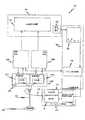
本発明の態様は、低侵襲手術システム100−たとえばインテューティブ・サージカル社(Intuitive Surgical)社によって市販されているダビンチ(登録商標)外科手術システム−内のカメラ120Lと120Rによる手術領域からの焦点の合った可視像と非可視像の取得を容易にする。一の態様では、カメラ120Lと120Rは、2つの視認モード−通常モードと1つ以上の拡大モード−を有する低侵襲手術システムにおいて用いられる。典型的には外科医のコンソール150上に設けられる表示モードのスイッチ152を用いることによって視認モードは切り換えられる。 Aspects of the present invention include focus from the surgical field by
通常の視認モードでは、手術領域の可視像は、カメラ120Lと120Rによって取得され、かつ、立体像の表示装置151内に表示される。拡大モードでは、非可視像はカメラ120Lと120Rによって取得される。取得された非可視像は、処理−たとえば可視の色成分を用いることによる偽着色−され、かつ、立体像の表示装置151内に表示される。一部の態様では、拡大モードはまた可視像を取得しても良い。 In the normal viewing mode, a visible image of the surgical region is acquired by the
カメラ120Lと120Rは、各異なる像が取得されるとき、そのカメラに対する焦点の調節を行うことなく、可視像と非可視像の両方を取込部121Lと121R上で適切に集束させる。一の態様では、カメラ120Lと120Rは、取込部121Lと121Rによって可視像を取り込むように焦点合わせされ、かつ、非可視像は、カメラ120Lと120Rに対する焦点の調節を行うことなく、同一の取込部121Lと121Rによって集束した状態で取得される。 When each different image is acquired, the
以降で詳述するように、カメラ120Lと120Rの各々は、内部にレンズ(又は屈折力を有する他のデバイス−たとえば屈折率の変化する2つの表面又は2つの材料−)を備えるプリズム素子を含む。たとえば一の態様では、レンズの代わりに回折素子が用いられる。回折素子は、波面を調節することのできる小さな構造を含む回折光学表面を有する。回折表面は、ホログラフィを含む多数の手法又はキノフォーム又は2つの表面を生成することによって作製されて良い。回折表面を備えるプリズム素子において、回折素子を通り抜ける光路は、そのような表面の実装を容易にする比較的制限された波長範囲を有して良い。 As will be described in more detail below, each of
一の態様では、非可視像を生成しうる非可視光がレンズを通過する。レンズは、非可視光の焦点を補正する。それにより非可視光の焦点は、可視光の焦点と略同一となる。 In one aspect, invisible light that can produce an invisible image passes through the lens. The lens corrects the focus of invisible light. Thereby, the focus of invisible light becomes substantially the same as the focus of visible light.
プリズム素子は、可視像への顕著な効果を有しない。カメラ120Lと120Rは、可視像と非可視像用の光学系により生成される様々な像の位置−面と呼ばれることもある−に対する解決法を提供する一方で、内視鏡101内での光学的な規定(optical prescription)を変化させることを必要としない。 The prism element has no significant effect on the visible image. While
カメラ120Lと120Rについてさらに詳細に検討する前に、低侵襲手術システム100について説明する。システム100は、単なる例示に過ぎず、かつ、カメラ120Lと120Rの用途をこの特定のシステムに限定することを意図していない。 Before considering the
低侵襲手術システム100−たとえばダビンチ(登録商標)外科手術システム−はカメラ120Lと120Rを含む。この例では、外科医のコンソール150にいる外科医は、ロボットマニピュレータアーム(図示されていない)上に設けられた内視鏡101を遠隔操作する。ダビンチ(登録商標)外科手術システムには他の部材、ケーブル等が存在するが、本開示からの逸脱を回避するために図1には図示されていない。低侵襲手術システムに関するさらなる詳細は特許文献2,3に記載されている。 A minimally invasive
照射システム−たとえばデュアルモード照射体110−は内視鏡101と結合する。デュアルモード照射体110は、白色光源111と蛍光励起源112を有する。照射源111と112の具体的な実施態様は重要ではない。デュアルモード照射体110は、立体像の内視鏡101内の少なくとも1つの照射路と併用されることで、細胞組織103に照射する。 An illumination system, such as
一例では、デュアルモード照射体110は2つの動作モードを有する。通常表示モードと拡大モードである。通常表示モードでは、白色光源111は、白色光を細胞組織103へ照射する。蛍光励起源112は通常表示モードでは用いられない。 In one example,
拡大表示モードでは、白色光源111は、一の態様として、1つ以上の可視の色成分を細胞組織103へ照射する。他の態様では、蛍光励起源112が起動しているとき、白色光の可視の色成分は用いられない。典型的には、3つ(以上の)可視の色成分は白色光を構成する。つまり白色光は、第1可視の色成分、第2可視の色成分、及び第3可視の色成分を有する。3つの可視の色成分の各々は各異なる可視の色成分−たとえば赤色成分、緑色成分、及び青色成分−である。たとえばシアンのようなさらなる色成分が用いられても良い。 In the enlarged display mode, the white light source 111 irradiates the
拡大表示モードでは、蛍光励起源112は、細胞組織103の蛍光像を励起する蛍光励起照射成分を供する。たとえば蛍光励起源112からの狭帯域光は、細胞組織に固有な近赤外光を放出する発光体を励起させるのに用いられる。それにより細胞組織103内の固有な細胞組織の蛍光像が、カメラ120Lと120Rによって取得される。 In the enlarged display mode, the
一の態様では、白色光源111は、各異なる可視の色照射成分の各々について光源を有する。赤色−緑色−青色の実施態様であれば、一例を挙げると、光源は、レーザー−赤色レーザー、緑色レーザー、及び青色レーザー−である。表1は、この例で用いられている核レーザーの出力波長の範囲を与える。 In one aspect, the white light source 111 has a light source for each of the different visible color illumination components. In the case of the red-green-blue embodiment, to name one example, the light sources are laser-red laser, green laser, and blue laser. Table 1 gives the output wavelength range of the nuclear laser used in this example.

蛍光励起波長が可視スペクトルの範囲外(たとえば近赤外(NIR)スペクトルの範囲内)に現れるとき、レーザーモジュール(又は他のエネルギー源−たとえば発光ダイオード又はフィルタリングされた白色光−)が蛍光励起源112として用いられる。 When the fluorescence excitation wavelength appears outside the visible spectrum (eg, within the near-infrared (NIR) spectrum), the laser module (or other energy source—such as a light emitting diode or filtered white light) —is the fluorescence excitation source. Used as 112.
よって一の態様では、蛍光は、蛍光励起源112内のレーザーモジュールからの光によって引き起こされる。例として蛍光は、808nmレーザーを用いて励起され、かつ、蛍光は835nmで最大となる。 Thus, in one aspect, the fluorescence is caused by light from a laser module in the
通常表示モード又は拡大表示モードでは、(複数の)光源からの光は、光ファイバの束116へ入射するように導光される。光ファイバの束116は、細胞組織103へ光を導光する立体像の内視鏡101内の照射路へ光を供する。 In the normal display mode or the enlarged display mode, light from the light source (s) is guided to enter the
一の態様では、内視鏡101はまた、細胞組織103からの光−たとえば反射白色光及び/又は蛍光−を通過させる2つの光学チャネルをも有する。反射白色光は通常可視像である。 In one aspect,
細胞組織103(図1)からの光は、カメラ120Lと120Rへ向かうように内視鏡101内の立体像の光路を通過する。以降で詳述するように、カメラ120Lは、プリズム素子、集束レンズ群、及びこの態様では、左側の像の電荷結合素子(CCD)121Lを有する。同様にカメラ120Rは、プリズム素子、集束レンズ群、及びこの態様では、右側の像の電荷結合素子(CCD)121Rを有する。 The light from the cell tissue 103 (FIG. 1) passes through the optical path of the stereoscopic image in the
様々な動作モードでは、左側の像のCCD121Lは左側の像を取得し、かつ、右側の像のCCD121Rは右側の像を取得する。左側の像のCCD121Lと右側の像のCCD121Rの各々は、各々が各異なる可視の色成分を取り込む複数のCCDであって良いし、又は、複数の異なる領域を有する単一のCCDであっても良い。3つのチップを供えるCCDセンサのみが図示されている。カラーフィルタアレイを備える単一のCMOSイメージセンサ又は3つのCMOSカラーイメージセンサ集合体が用いられても良い。 In various modes of operation, the
カメラ120Lは、左側のカメラ制御ユニット130Lによって、外科医のコンソール150内にある立体像表示装置151と結合する。カメラ120Rは、左側のカメラ制御ユニット130Rによって、外科医のコンソール150内にある立体像表示装置151と結合する。カメラ制御ユニット130Lと130Rは、システム処理装置162からの信号を受信する。システム処理装置162は、システム100の様々な制御装置を表す。 The
表示モード選択スイッチ152は、選択された表示モードをシステム処理装置162へ渡すユーザーインターフェース161へ信号を供する。システム処理装置162内の様々な制御装置は、デュアルモード照射体110内に出力とレベルを制御する装置115を配置し、所望の像を取得するように左側のカメラの制御ユニット130Lと右側のカメラの制御ユニット130Rを配置し、かつ、取得された像を処理するのに必要な任意の他の素子を配置する。それにより要求する像が、表示装置150において外科医に与えられる。 Display
表示用に取得された可視像と蛍光像を結合するために用いられる具体的手法は、可視像と非可視像との間での焦点の差異を補正する新規方法を理解する上で重要ではない。視認モード−視認のみ、蛍光のみ、又は視認と蛍光の結合−によらず、焦点が可視像用に設定された後にシステムに対する調節を行うことなく−つまり内視鏡の光学系を変化させることなく、カメラの焦点を変化させることなく、及び、取得された可視像と蛍光像との間での焦点の差異を補償するために取得された像を処理することなく−、取得された像と表示された像のいずれもが概ね焦点が合った状態のままである。 The specific technique used to combine the visible and fluorescent images acquired for display is in order to understand a new method for correcting the focus difference between visible and invisible images. It does not matter. Regardless of the viewing mode-viewing only, fluorescence only, or the combination of viewing and fluorescence-without adjusting the system after the focus is set for the visible image-i.e. changing the optics of the endoscope Acquired images without changing the focus of the camera and without processing the acquired images to compensate for differences in focus between the acquired visible and fluorescent images All of the images displayed as are generally in focus.
図2は、内視鏡101の各像チャネルと併用される従来技術に係るカメラ220のブロック図である。内視鏡像201は内視鏡101から得られた細胞組織103の像である。像201は、集束レンズ群223−これは集束ユニットの一例である−へ向かうように前方窓222を通過する。 FIG. 2 is a block diagram of a
集束レンズ群223は、カメラ220の長手軸に沿って移動する。集束レンズ群223は、像201がCCDプリズムブロック224内のCCD221上で集束するように位置設定される。残念なことに、上述したように、焦点は可視像と非可視像で異なる。 The focusing
像201が可視像である場合、集束レンズ群223は、CCD221上で(複数の)可視成分を集束させるように第1位置に設置される。像201が非可視像−たとえば700nm〜1000nmの範囲内の波長を含む近赤外スペクトル範囲内の像−である場合、集束レンズ群223は、CCD221上で非可視像を集束させるように第2位置に設置される。第1位置と第2位置は異なる。焦点におけるこのような差異は、蛍光像の取り込みから可視像の取り込みへ移行するとき又はその逆を行う際に特に顕著となる。 When the
図3は、内視鏡101の各チャネルと併用される新規焦点補正組立体のブロック図である。この例では、新規焦点補正組立体はカメラ120Aに含まれる。カメラ120Aは、カメラ120Lとして用いられ良いし、かつ、カメラ120Rとして用いられても良い。また新規焦点補正集合体は単色の内視鏡と併用されても良い。カメラ120Aでは、従来技術に係る前方窓222はもはや用いられず、その代わりにプリズム素子−プリズム集合体と呼ばれることもある−が用いられる。プリズム素子330はレンズ331を有する。集束レンズ群223、CCDプリズムブロック224、及びCCD221は、従来技術に係るカメラ220と同一で、かつ、一の態様ではカメラ120A内で直接−つまり変化させずに−用いられる。集束レンズ群223は焦点ユニットである。CCDプリズムブロック224とCCD221は像取り込みユニットである。 FIG. 3 is a block diagram of a novel focus correction assembly used in combination with each channel of the
以降で詳述するように、一の態様では、内視鏡101からのレンズ331は非可視光の焦点を補正する。それにより非可視光から生成される非可視像の焦点は、内視鏡101からの可視光から生成される可視像の焦点と略同一となる。ここで「略同一」の焦点及び「実質的に」焦点が合っているとは、非可視像と可視像が人間によって視認されているときに、その2つの像の差異が、その人間にとって顕著ではない−つまりその2つの像の外見上の鮮明さが同様である−ことを意味する。実際近赤外像の回折限界の鮮明さは、波長が長くなることで、可視像の回折限界の鮮明さよりも低くなる。実際の光学系は、波長による像の鮮明さに影響を及ぼす他の収差を有することがある。 As described in detail below, in one aspect, the
また「人間が非可視像を見る」という記載は、取得された非可視像がシステム100内で処理−たとえば偽着色−されることで、その非可視像が、可視像として表示装置151内に与えられ得ることを意味する。この処理は、カメラ120Aによって取得された像で実行されるので、本明細書で述べたようにカメラ120Aの動作に影響を及ぼす。偽着色の例は特許文献4に記載されている。 In addition, the statement “a human sees an invisible image” means that the acquired invisible image is processed in the
上述の例及び以降の例では、非可視光はレンズを通過し、かつ、可視光はプリズム素子を直接通過する。これは単なる例示であって、限定を意図するものではない。本開示を考慮すると、当業者は、係る用途が有利なときには、レンズを用いて可視光の焦点を補正し、かつ、非可視光にプリズム素子を通過させることができる。よってより一般的な表記では、可視光と非可視光のうちの一はレンズを通過する。可視光と非可視光のうちの他はプリズム素子を直接通過する。 In the above example and the following examples, invisible light passes through the lens and visible light passes directly through the prism element. This is merely an example and is not intended to be limiting. In view of this disclosure, those skilled in the art can use a lens to correct the focus of visible light and allow non-visible light to pass through the prism element when such applications are advantageous. Thus, in a more general notation, one of visible light and invisible light passes through the lens. Other than visible light and non-visible light pass directly through the prism element.
図3の例では、内視鏡からの光301は、可視光301Vと非可視光301NVを含む。換言すると、光301は可視光波長301Vと非可視光波長301NVを含む。可視光301Vはプリズム素子330を直接通過する。しかしプリズム素子330の表面302−これは第1表面の例である−は、非可視光301NVを反射して、可視光301Vを通過させるコーティングを有する。よってそのコーティングは、光301から非可視光301NVを取り出す。つまりこの結果、可視光301V−これは可視像を生成しうる−が、非可視光301NV−これは非可視像を生成しうる−から分離される。 In the example of FIG. 3, the light 301 from the endoscope includes
取り出された非可視光301NVはレンズ331を通過する。これにより、光301NVによって生成された像の焦点が補正され、焦点補正された非可視光301NV_CORRECTが生成される。焦点補正された非可視光301NV_CORRECTは、プリズム素子330によって可視光301Vと再結合する。その再結合した光は集束レンズ群223を通過する。ここで、焦点補正された非可視光301NV_CORRECTと可視光301Vは、同一の擬似的位置を有するので、集束レンズ群223は、2つの像をCCD221上で適切に集束する。 The extracted invisible light 301NV passes through the
プリズム素子とレンズ331は、以降で詳述するように様々な方法で形成されて良い。一の態様では、レンズ331は可変である。よってレンズは、特定の内視鏡向けに特化されて良く、かつ、プリズム素子330内に挿入されて良い。他の内視鏡が異なるレンズを必要とする場合には、そのレンズは相互に交換可能である。よって、適切なレンズ−たとえば内視鏡からの非可視像の焦点を補正するレンズ−が利用可能である限り、カメラ120Aは任意の内視鏡と併用されて良い。 The prism element and the
他の態様では、レンズ331は、プリズムの面内又はプリズム素子330内のプリズムの面内に形成される。この態様では、プリズム素子は内視鏡の型に関連する。特定の内視鏡については、その内視鏡からの非可視像の焦点を補正するプリズム素子が、カメラ120A内に挿入される。 In other embodiments, the
従って一の態様では、低侵襲手術システムは、結像面−たとえばCCD221−及び焦点補正集合体350を有する。焦点補正集合体350は第1光路及び第2光路を有する。第1光路及び第2光路のいずれも、共通開始位置351と共通終了位置352との間で延びている。第2光路は第1光路よりも長い。第2光路はレンズ331を含む。像焦点補正集合体350が構成及び位置設定されることで、開始位置351から終了位置352へ向かうように第1光路を通過する第1スペクトル内の光と、開始位置351から終了位置352へ向かうように第2光路を通過する第1スペクトル内の光の両方が、結像面221上で集束することで、結像面221上で実質的に焦点合わせされた状態の像を生成する。 Thus, in one aspect, a minimally invasive surgical system has an imaging plane—eg,
一の態様では、第1光路は実質的に直線で、かつ、第2光路は折れ曲がっている。第2光路は、第1スペクトルを通過させ、かつ、第2スペクトルを反射する表面302を含む。一の態様では、以降で詳述するように、第1スペクトルは可視スペクトルの少なくとも一部を含み、かつ、第2スペクトルは赤外スペクトルの少なくとも一部を含む。他の態様では、第2スペクトルは、医療用発光体の蛍光スペクトルである。 In one aspect, the first optical path is substantially straight and the second optical path is bent. The second optical path includes a
繰り返しになるが、一の従来技術に係る解決法は、屈折率の異なる複数の材料を用いることで、可視像と非可視像との間で焦点を補正した。その際焦点長の差異に基づく異なるサイズの構造が必要とされた。対照的に、一の態様において、カメラ120Aでは、プリズム素子330のサイズは変化せず、かつ、素子330内のレンズの屈折力が変化する。 Again, one prior art solution corrected the focus between visible and invisible images by using multiple materials with different refractive indices. At that time, structures of different sizes based on differences in focal length were required. In contrast, in one embodiment, in
図4Aと図4Bは、特定の内視鏡に対して適切なレンズを決定する方法の例である。図4Aは12mmの内視鏡用である(12mmとはその内視鏡の外径を表す)。内視鏡の設計波長は486nm、587nm、及び656nmである。内視鏡は、近赤外−たとえば850nm−では十分に集束しない。曲線401は、可視像についての対象物の焦点位置に対する距離の変化である。曲線402は、850nmでの近赤外範囲の非可視像についての対象物の焦点位置に対する距離の変化である。曲線403は、曲線401と曲線402の差である。 4A and 4B are examples of methods for determining an appropriate lens for a particular endoscope. FIG. 4A is for a 12 mm endoscope (12 mm represents the outer diameter of the endoscope). The design wavelengths of the endoscope are 486 nm, 587 nm, and 656 nm. Endoscopes do not focus well in the near infrared—for example 850 nm. A
曲線403によって示されているように、焦点位置の差は、対象物の距離の範囲全体にわたって実効的に一定である。よってこの内視鏡のレンズ331は、曲線403によって表される焦点の差δを補償するように選ばれる。それにより内視鏡からの近赤外光がレンズ331を通過するときには、焦点が補正され、かつ、曲線401と曲線402の関心作動距離が一致する。 As shown by
図4Bは8.5mmの内視鏡用である。曲線411は、可視像についての対象物の焦点位置に対する距離の変化である。曲線412は、850nmでの近赤外範囲の非可視像についての対象物の焦点位置に対する距離の変化である。曲線413は、曲線411と曲線412の差である。 FIG. 4B is for an 8.5 mm endoscope. A
この例では、図4Aと図4Bでの焦点の差異は、共通のレンズを用いて補正するには大き過ぎる。よって2つの異なるレンズが用いられる。前記2つの異なるレンズのうちの一は、曲線403によって表される補正に必要で、前記2つの異なるレンズのうちの他は、曲線413によって表される補正に必要である。 In this example, the difference in focus in FIGS. 4A and 4B is too large to be corrected using a common lens. Thus, two different lenses are used. One of the two different lenses is necessary for the correction represented by
曲線413によって表されているように、焦点位置の差異は、関心対象物距離の範囲全体にわたって比較的一定である。この例では、図4Aと図4Bでの焦点位置の差異は、共通のレンズを用いて補正するには大き過ぎる。よって2つの異なるレンズが用いられる。前記2つの異なるレンズのうちの一は、曲線403によって表される補正に必要で、前記2つの異なるレンズのうちの他は、曲線413によって表される補正に必要である。よって図4Bのデータを生成するのに用いられるこの内視鏡用のレンズは、曲線413によって表される焦点の差δを補償するように選ばれる。それにより近赤外像がレンズ331を通過するとき、焦点が補正され、かつ、曲線411と曲線412の関心作動距離は一致する。 As represented by
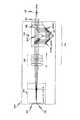
図5は、プリズム素子330の一例をより詳細に表している。プリズム素子330Aは、図5に図示されたように切頭型の大きな直角プリズム501を有する。切頭の寸法は重要ではない。プリズム素子330はまた、2つの偏菱形プリズム502と503及びレンズ531をも有する。 FIG. 5 shows an example of the
この例では、レンズ531は、ダブレットを形成するように、一の型のガラスの凹レンズ533と他の型のガラスの凸レンズ532とが組み合わせられたものである。レンズ531は、プリズム集合体を製造するのに便利な厚さを有し、かつ、要求される焦点補正を行う。 In this example, the
当業者によって知られているように、偏菱形プリズムは、像中の角度のずれも配向の変化も生じさせることなく入射ビームを変位させる。偏菱形プリズム502は、第1面502_TOP上に第1コーティングを有し、及び、任意で、第1面502_TOPとは反対で、かつ第1面502_TOPから離れている第2面502_BOTTOM上に第2コーティングを有する。偏菱形プリズム503もまた、第1面503_TOP上に第1コーティングを有し、及び、任意で、第1面503_TOPとは反対で、かつ第1面503_TOPから離れている第2面503_BOTTOM上に第2コーティングを有する。 As is known by those skilled in the art, rhomboid prisms displace the incident beam without causing an angular shift or orientation change in the image. The
一の態様では、非可視像が、電磁放射線スペクトルの近赤外部分に属しているとき、第1コーティングは、808nm付近で遷移する短波長を通過させて長波長を反射するコーティングである。このことは、第1コーティングが、約808nmよりも短い波長を通過させ、かつ、約808nmよりも長い波長を反射させることを意味する。一の態様では、このコーティングは、プリズムガラス502_TOPと503_TOP上に存在し、かつ、プリズム501に対する光学接合剤によって挟まれている。よってコーティングは埋め込まれている。コーティングはまた、偏菱形プリズムの代わりにプリズム501の脚部に設けられても良い。第2コーティングは非可視光を反射するだけで良く、特別なバンドパス特性を有する必要はない。第2コーティングは金属ミラーコーティングにより実装されてよい。他の態様では、この表面で全内部反射を利用することも可能である。しかし製造の容易さと取り扱いの簡便さを考慮すると、金属ミラーコーティングがよく機能する。 In one aspect, when the non-visible image belongs to the near infrared portion of the electromagnetic radiation spectrum, the first coating is a coating that reflects a long wavelength by passing a short wavelength that transitions near 808 nm. This means that the first coating passes wavelengths shorter than about 808 nm and reflects wavelengths longer than about 808 nm. In one embodiment, the coating is present on the prism glasses 502_TOP and 503_TOP and is sandwiched by an optical adhesive to the
第1及び第2は、コーティング同士を区別する形容詞として用いられているのであり、特定の表面上のコーティングの数を表しているのではない。また上部、下部、及び側部は、図中の素子同士の区別を容易にし、かつ、素子同士の相対的な関係を視覚化するのを助ける形容詞として用いられている。たとえば上部(表)面と下部(表)面は、互いに対向して離れている第1表面と第2表面である。側部面は、第1面と第2面との間で延びる第3表面である。 The first and second are used as adjectives to distinguish between coatings and do not represent the number of coatings on a particular surface. The upper part, the lower part, and the side part are used as adjectives that facilitate the distinction between elements in the figure and help visualize the relative relationship between the elements. For example, the upper (front) surface and the lower (front) surface are a first surface and a second surface that are separated from each other. The side surface is a third surface extending between the first surface and the second surface.
上部、下部、及び側部は、絶対的な物理的位置を定義するものとして用いられていない。実装においては、内視鏡像601(図6A)は、カメラの物理的下部に入り込む。その際プリズム素子330は、カメラの物理的底部に設けられる。よってプリズム素子がカメラ内に存在し、かつ、そのカメラが内視鏡と接続されるとき、内視鏡の像601が入り込む図6Aの偏菱形502の部分は、プリズムの下部である。 The top, bottom, and sides are not used to define absolute physical positions. In the implementation, the endoscopic image 601 (FIG. 6A) enters the physical bottom of the camera. In this case, the
図6A〜図6Eは、カメラ120A内でのプリズム素子330(図3及び図5)の動作を説明するのに用いられる。内視鏡からの光は像の生成に用いられる。本開示においては、この光を「内視鏡の像」601(図6A)と呼ぶことにする。内視鏡の像601は、可視光から生成される可視像及び非可視光から生成される非可視像を含む。内視鏡の像601は最初に窓602を通過する。窓602に隣接する偏菱形プリズム502の側面は、一の態様では正方形だが、カメラの壁内の開口部は円形である。よってこの態様では、窓602は環状の窓である。一の態様では、プリズム素子330の厚さは16mmで、かつ、厚さ1mmの環状の窓が、偏菱形プリズム502の側面に小さな空気ギャップ(図示されていない)を備えた状態で設けられている。一の態様では、窓602はスコットBK7ガラス窓である。 6A to 6E are used to explain the operation of the prism element 330 (FIGS. 3 and 5) in the
窓602を通過した後、内視鏡の像601は、偏菱形プリズム502の面502_TOP上の第1コーティングへ向かうように偏菱形プリズム502の側壁を通過する(図6A)。第1面の例である面502_TOP上の第1コーティングは、可視光601Vから非可視光601NV(図6B)を分離する。具体的には可視光601Vは第1コーティングを通過する。非可視光601NVは、偏菱形プリズム502の面502_TOP上の第1コーティングによって反射される。 After passing through the
反射された非可視光601NVは、第2面の例である面502_BOTTOM上の第2コーティングによって再度反射される。第2コーティングから反射された非可視光はレンズ531を通過する(図6C)。レンズ531は、非可視光601NVの焦点を補正する。焦点補正された非可視光601NVは、第3面の例である偏菱形プリズム503の面503_BOTTOM上の第2コーティングによって反射される(図6D)。 The reflected invisible light 601NV is reflected again by the second coating on the surface 502_BOTTOM, which is an example of the second surface. Invisible light reflected from the second coating passes through the lens 531 (FIG. 6C). The
偏菱形プリズム503の面503_BOTTOM上の第2コーティングによって反射された焦点補正された非可視光601NV(図6D)は、第3面に対向して、その第3面から離れている第4面の例である偏菱形プリズム503の面503_TOP上の第1コーティングによって再度反射される。偏菱形プリズム503の面503_TOP上の第1コーティングは可視光601Vをも通過させる。よって偏菱形プリズム503の面503_TOP上の第1コーティングは、可視光601Vと焦点補正された非可視光601NVとを再結合する。再結合した光は集束レンズ群223を通過する。その結果、可視光像と非可視光像の両方がCCD221上に正しく生成される。 Defocused invisible light 601NV (FIG. 6D) reflected by the second coating on surface 503_BOTTOM of
レンズ531を備えるプリズム素子330は、ずれた可視焦点と非可視焦点を修正する。プリズム素子330は、カメラの前方窓に置き換わるものだが、焦点補正を実装するのに、カメラ又は内視鏡に対して他に修正を行う必要はない。 The
上述の例は、近赤外スペクトルにおける非可視光についてであった。しかし本開示を考慮すると、プリズム素子は、適切なコーティングを選ぶことによって、電磁放射線スペクトルの他の部分における非可視光についても実装可能である。また上述の例では、非可視光の焦点は補正され、かつ、可視光は単純にプリズム素子を通過する。一部の態様では、可視光の焦点を補正し、かつ、レンズを備えるプリズム素子を用いることによって可視光を通過させることは有利となりうる。他の態様では、可視光と非可視光のいずれも、所望の焦点が得られるように、プリズム素子内のレンズを通過して良い。 The above example was for invisible light in the near infrared spectrum. However, in view of the present disclosure, prism elements can also be implemented for invisible light in other parts of the electromagnetic radiation spectrum by choosing an appropriate coating. In the above example, the focus of the invisible light is corrected, and the visible light simply passes through the prism element. In some aspects, it may be advantageous to pass visible light by correcting the focus of visible light and using a prism element with a lens. In other embodiments, both visible and invisible light may pass through the lens in the prism element so that the desired focus is obtained.
上述したプリズム素子330のプリズムは、単なる例示に過ぎず、限定を意図するものではない。上述の記載を考慮すると、当業者は、可視光と非可視光とを分離する素子を実装し、2つの像のうちの一に対応する光の焦点を補正し、その後、光を再結合する。たとえば図7A〜図7Eは、プリズム素子330の代替実施例を表している。 The prisms of the
図7A〜図7Eでは、実線は、可視光と非可視光の両方を含む内視鏡からの光と、焦点補正された像の生成を可能にする再結合された光を表すのに用いられる。破線は、内視鏡の光から取り出され、かつ、一般的には焦点補正される光を表す。一点破線は、プリズム素子を通過する光を表すのに用いられる。具体的な実施例に依存して、焦点補正された光の成分は、可視光及び/又は非可視光であって良い。適切なコーティングが、2つの光の成分のうちの一を通過させ、かつ、前記2つの光の成分のうちの他を反射するように選ばれる。光の成分は非可視光と可視光である。 In FIGS. 7A-7E, solid lines are used to represent the light from the endoscope, including both visible and invisible light, and the recombined light that enables the generation of a focus-corrected image. . Dashed lines represent light that is extracted from the light of the endoscope and is generally focus corrected. A dashed line is used to represent light passing through the prism element. Depending on the specific embodiment, the focus corrected light component may be visible light and / or invisible light. A suitable coating is chosen to pass one of the two light components and reflect the other of the two light components. The light components are invisible light and visible light.
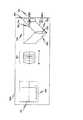
図7Aでは、プリズム素子330Aは、6個の直角プリズム701、702、703、704、705、及び706と、レンズ331Aを有する。スペーサ707がプリズム702と703との間に設けられる。レンズ331Aは、スペーサ707に隣接して、かつ、プリズム705と706との間に設けられる。スペーサ707の位置とレンズ331Aの位置は相互に交換可能である。またスペーサ707は第2レンズに置き換えられても良い。通過と反射を行うコーティング−たとえば第1コーティング−が、プリズム701と704の表面上に設けられる。反射コーティング−たとえば第2コーティング−はプリズム705と706の表面上に設けられる。 In FIG. 7A, the
プリズム素子330Aは一種類のプリズムを用いる。そのようにするのは製造上便利だからである。通過と反射を行うコーティングは、プリズム701又はプリズム702のいずれかの斜面上、及び、プリズム704又はプリズム703のいずれかの斜面上に設けられて良く、かつ、コーティングの設計は、プリズム701をプリズム702へ固定し、かつ、プリズム703をプリズム704へ固定するのに用いられる結合法を行うのに十分な余裕を必要とする。プリズム素子330Aは、図7Bの偏菱形と比較して、プリズム705と706のガラスの選択においてより大きな自由度を与える。プリズム701、702、703、及び704は、単純な場合では、(要求されているわけではないが)全て同一のガラスである。しかしプリズム705と706は非可視光路中にしか存在せず、かつ、プリズム705と706を通過する光線は、ある波長群に属するので、プリズム705と706は異なる材料で作られても良い。 The
図7Bでは、プリズム素子330Bは、2つの直角プリズム710と711、2つの偏菱形プリズム712と713、及びレンズ331Bを有する。スペーサ714がプリズム710と711との間に設けられる。レンズ331Bは、スペーサ714に隣接し、かつ、プリズム712と713の間に設けられる。スペーサ714の位置とレンズ331Bの位置は相互に交換可能である。またスペーサ714は第2レンズに置き換えられても良い。偏菱形プリズム712と713は、上の図5で説明した偏菱形プリズムと同等のコーティングを有する。プリズム素子330Bが有する素子は、プリズム素子330Aが有する素子よりも少ないので、接合される表面は少なくなる。その結果良好な位置合わせが実現される。 In FIG. 7B, the
図7Cでは、プリズム素子330Cは、2つの立方体ビームスプリッタ720と721、2つの直角プリズム722と723、及び、レンズ331Cを有する。スペーサ724が、立方体ビームスプリッタ720と721との間に設けられる。レンズ331Cは、スペーサ724に隣接し、かつ、プリズム722と723の間に設けられる。スペーサ724の位置とレンズ331Cの位置は相互に交換可能である。またスペーサ724は第2レンズに置き換えられても良い。 In FIG. 7C, the
図7Dでは、プリズム素子330Dは、1つの大きな直角プリズム730、4つの小さな直角プリズム731、732、733、734、及びレンズ731Dを有する。プリズム730は、レンズ731Dがプリズム733と734との間に設けられうるように、切頭形の上部を有する。プリズム素子330Dは、プリズム733と734のガラスの選択を可能にする。またこの構成では、所望であれば後述のように、レンズ331Dをプリズム733と734の一部とすることが可能となる。 In FIG. 7D, the
図7Eでは、プリズム素子330Eは、1つの大きな直角プリズム740、2つの小さな直角プリズム741、742、及び、各々がレンズ331Eを形成するように構成される面を有する2つのプリズム743と744を有する。あるいはその代わりにプリズム741と743は、図7Eに図示されているように構成された面を備える偏菱形プリズムとして実装されてもよい。プリズム743と744はそれぞれ異なるガラスである。プリズム743と744はまた、それらの斜面上に半径をも有して良い。 In FIG. 7E,
Claims (22)
Translated fromJapanese前記可視光を前記非可視光から分離する手順;
前記可視光と非可視光のうちの一にレンズを通過させる手順であって、前記レンズは、前記可視光と非可視光のうちの一から生成される像の焦点を補正することで、前記像の焦点が、前記可視光と非可視光のうちの他から生成される像の焦点と同一となる、手順;
前記レンズからの前記可視光と非可視光のうちの一と、前記レンズからの前記可視光と非可視光のうちの他とを再結合する手順;
を有する方法。Receiving light, including visible and invisible light, from a minimally invasive surgical device;
Separating the visible light from the invisible light;
A step of passing a lens through one of the visible light and invisible light, wherein the lens corrects a focus of an image generated from one of the visible light and invisible light, A procedure in which the focus of the image is the same as the focus of the image generated from the other of the visible light and the invisible light;
Recombining one of the visible and invisible light from the lens and the other of the visible and invisible light from the lens;
Having a method.
前記可視光と非可視光のうちの他は前記表面コーティングを通過し、かつ
前記可視光と非可視光のうちの一は前記表面コーティングによって反射されることで、第1反射光が生成される、
請求項1に記載の方法。The step of separating further comprises passing the visible light and the invisible light toward a first surface having a surface coating that passes and reflects;
The other one of the visible light and the invisible light passes through the surface coating, and one of the visible light and the invisible light is reflected by the surface coating, thereby generating a first reflected light. ,
The method of claim 1.
前記第1反射光は前記第2表面コーティングによって反射されることで、第2反射光が生成される、
請求項3に記載の方法。The step of separating further comprises passing the first reflected light toward a second surface having a second surface coating;
The first reflected light is reflected by the second surface coating to generate a second reflected light,
The method of claim 3.
前記レンズは、前記可視光と非可視光のうちの一から生成される像の焦点を補正することで、前記像の焦点が、前記可視光と非可視光のうちの他から生成される像の焦点と同一となる、
低侵襲手術システム。A minimally invasive surgical system comprising a camera including a prism element having a lens therein,
The lens corrects a focal point of an image generated from one of the visible light and invisible light, so that the focal point of the image is generated from the other of the visible light and invisible light. The same focus as
Minimally invasive surgery system.
前記コーティングは、前記可視光と非可視光のうちの他を通過させ、かつ、前記可視光と非可視光のうちの一を反射する、
請求項9に記載の低侵襲手術システム。The prism element further comprises a first surface having a coating for passing and reflecting;
The coating allows the other of the visible light and invisible light to pass through and reflects one of the visible light and invisible light;
The minimally invasive surgical system according to claim 9.
前記第2表面は、前記第1表面に対向し、かつ、前記第1表面から離れている、
請求項10に記載の低侵襲手術システム。The prism element further comprises a second surface having a reflective coating;
The second surface is opposite the first surface and away from the first surface;
The minimally invasive surgical system according to claim 10.
前記第3表面は、前記第1表面とは異なる、
請求項10に記載の低侵襲手術システム。The prism element further comprises a third surface having a coating for passing and reflecting;
The third surface is different from the first surface;
The minimally invasive surgical system according to claim 10.
前記焦点補正組立体は、第1光路と、レンズを有する第2光路と、共通の開始位置と、共通の終了位置を含み、
前記第2光路は前記第1光路よりも長く、
前記カメラに対する前記焦点補正組立体の構成及び位置は、前記開始位置から前記第1光路を通過して前記終了位置へ向かう第1スペクトル内の光と、前記開始位置から前記第2光路を通過して前記終了位置へ向かう第2スペクトル内の光のいずれもが、前記結像面上で集束されることで、前記結像面上で実質的に集束する可視像と非可視像が生成されるようなものである、
低侵襲手術システム。A minimally invasive surgical system having a camera having an imaging plane and a focus correction assembly,
The focus correction assembly includes a first optical path, a second optical path having a lens, a common start position, and a common end position,
The second optical path is longer than the first optical path,
The configuration and position of the focus correction assembly relative to the camera includes light in a first spectrum from the start position through the first optical path to the end position and from the start position through the second optical path. Thus, any light in the second spectrum going to the end position is focused on the imaging plane, thereby generating a visible image and an invisible image that are substantially focused on the imaging plane. Is like,
Minimally invasive surgery system.
前記第2スペクトルは前記赤外スペクトルの少なくとも一部を含む、
請求項17に記載の低侵襲手術システム。The first spectrum includes at least a portion of the visible spectrum; and
The second spectrum includes at least a portion of the infrared spectrum;
The minimally invasive surgical system according to claim 17.
前記可視光を前記非可視光から分離する手順;
前記可視光と非可視光のうちの一にレンズを通過させる手順であって、前記レンズは、前記可視光と非可視光のうちの一から生成される像の収差を調節することで、前記像の焦点が、前記可視光と非可視光のうちの他から生成される像の焦点と同一となる、手順;
前記レンズからの前記可視光と非可視光のうちの一と、前記レンズからの前記可視光と非可視光のうちの他とを再結合する手順;
を有する方法。Receiving light, including visible and invisible light, from a minimally invasive surgical device;
Separating the visible light from the invisible light;
A step of passing a lens through one of the visible light and invisible light, the lens adjusting the aberration of an image generated from one of the visible light and invisible light, A procedure in which the focus of the image is the same as the focus of the image generated from the other of the visible light and the invisible light;
Recombining one of the visible and invisible light from the lens and the other of the visible and invisible light from the lens;
Having a method.
Applications Claiming Priority (5)
| Application Number | Priority Date | Filing Date | Title |
|---|---|---|---|
| US36127210P | 2010-07-02 | 2010-07-02 | |
| US61/361,272 | 2010-07-02 | ||
| US12/855,934 | 2010-08-13 | ||
| US12/855,934US8295693B2 (en) | 2010-07-02 | 2010-08-13 | Dual optical path prism and camera in a minimally invasive surgical system |
| PCT/US2011/041468WO2012003126A1 (en) | 2010-07-02 | 2011-06-22 | Dual optical path prism and camera in a minimally invasive surgical system |
Related Child Applications (1)
| Application Number | Title | Priority Date | Filing Date |
|---|---|---|---|
| JP2016153597ADivisionJP6203345B2 (en) | 2010-07-02 | 2016-08-04 | Camera in minimally invasive surgical system |
Publications (2)
| Publication Number | Publication Date |
|---|---|
| JP2013531537Atrue JP2013531537A (en) | 2013-08-08 |
| JP5986076B2 JP5986076B2 (en) | 2016-09-06 |
Family
ID=44509593
Family Applications (4)
| Application Number | Title | Priority Date | Filing Date |
|---|---|---|---|
| JP2013518486AActiveJP5986076B2 (en) | 2010-07-02 | 2011-06-22 | Minimally invasive surgery system |
| JP2016153597AActiveJP6203345B2 (en) | 2010-07-02 | 2016-08-04 | Camera in minimally invasive surgical system |
| JP2017164114AActiveJP6640801B2 (en) | 2010-07-02 | 2017-08-29 | Cameras in minimally invasive surgery systems |
| JP2019235598AActiveJP6965334B2 (en) | 2010-07-02 | 2019-12-26 | How to operate the camera in a minimally invasive surgical system |
Family Applications After (3)
| Application Number | Title | Priority Date | Filing Date |
|---|---|---|---|
| JP2016153597AActiveJP6203345B2 (en) | 2010-07-02 | 2016-08-04 | Camera in minimally invasive surgical system |
| JP2017164114AActiveJP6640801B2 (en) | 2010-07-02 | 2017-08-29 | Cameras in minimally invasive surgery systems |
| JP2019235598AActiveJP6965334B2 (en) | 2010-07-02 | 2019-12-26 | How to operate the camera in a minimally invasive surgical system |
Country Status (6)
| Country | Link |
|---|---|
| US (2) | US8295693B2 (en) |
| EP (2) | EP2587982B1 (en) |
| JP (4) | JP5986076B2 (en) |
| KR (4) | KR101853641B1 (en) |
| CN (2) | CN102958420B (en) |
| WO (1) | WO2012003126A1 (en) |
Cited By (2)
| Publication number | Priority date | Publication date | Assignee | Title |
|---|---|---|---|---|
| JP2019000339A (en)* | 2017-06-14 | 2019-01-10 | パナソニックIpマネジメント株式会社 | Endoscope and camera head |
| JP2023089720A (en)* | 2021-12-16 | 2023-06-28 | スタンレー電気株式会社 | optical device, optical system |
Families Citing this family (40)
| Publication number | Priority date | Publication date | Assignee | Title |
|---|---|---|---|---|
| US8039397B2 (en) | 2008-11-26 | 2011-10-18 | Applied Materials, Inc. | Using optical metrology for within wafer feed forward process control |
| US8295693B2 (en) | 2010-07-02 | 2012-10-23 | Intuitive Surgical Operations, Inc. | Dual optical path prism and camera in a minimally invasive surgical system |
| MX350734B (en) | 2010-09-08 | 2017-09-15 | Covidien Lp | Catheter with imaging assembly. |
| JP2012078503A (en)* | 2010-09-30 | 2012-04-19 | Olympus Corp | Illumination device and observation system |
| US10327818B2 (en)* | 2012-06-18 | 2019-06-25 | Bruce Francis Hodgson | Method and apparatus for the treatment of scoliosis |
| US9615728B2 (en) | 2012-06-27 | 2017-04-11 | Camplex, Inc. | Surgical visualization system with camera tracking |
| US9642606B2 (en) | 2012-06-27 | 2017-05-09 | Camplex, Inc. | Surgical visualization system |
| EP2872026B1 (en)* | 2012-07-13 | 2021-12-08 | Steris Instrument Management Services, Inc. | Stereo endoscope system |
| US9198835B2 (en) | 2012-09-07 | 2015-12-01 | Covidien Lp | Catheter with imaging assembly with placement aid and related methods therefor |
| USD735343S1 (en) | 2012-09-07 | 2015-07-28 | Covidien Lp | Console |
| USD717340S1 (en) | 2012-09-07 | 2014-11-11 | Covidien Lp | Display screen with enteral feeding icon |
| US9517184B2 (en) | 2012-09-07 | 2016-12-13 | Covidien Lp | Feeding tube with insufflation device and related methods therefor |
| USD716841S1 (en) | 2012-09-07 | 2014-11-04 | Covidien Lp | Display screen with annotate file icon |
| CN103006170B (en)* | 2012-12-16 | 2014-08-13 | 天津大学 | Medical endoscope three-dimensional imaging device |
| US9782159B2 (en) | 2013-03-13 | 2017-10-10 | Camplex, Inc. | Surgical visualization systems |
| DE102013212111A1 (en) | 2013-06-25 | 2015-01-22 | Henke-Sass, Wolf Gmbh | Endoscope and endoscopy procedure |
| US10028651B2 (en) | 2013-09-20 | 2018-07-24 | Camplex, Inc. | Surgical visualization systems and displays |
| EP3046458B1 (en) | 2013-09-20 | 2020-10-21 | Camplex, Inc. | Surgical visualization systems |
| CN104107026A (en)* | 2014-03-07 | 2014-10-22 | 董国庆 | Dual-optical-path binocular-lens hard tube type endoscope |
| EP3226799A4 (en) | 2014-12-05 | 2018-07-25 | Camplex, Inc. | Surgical visualization systems and displays |
| WO2016154589A1 (en) | 2015-03-25 | 2016-09-29 | Camplex, Inc. | Surgical visualization systems and displays |
| US10126541B2 (en)* | 2015-03-26 | 2018-11-13 | Steris Instrument Management Services, Inc. | Endoscopic illuminating and imaging systems and methods |
| WO2017091704A1 (en) | 2015-11-25 | 2017-06-01 | Camplex, Inc. | Surgical visualization systems and displays |
| CN105739281B (en) | 2016-04-14 | 2018-12-21 | 京东方科技集团股份有限公司 | Image display system and image display method |
| CN105898217B (en)* | 2016-04-14 | 2019-08-06 | 京东方科技集团股份有限公司 | Holographic operating device and control device, holographic operating method and control method |
| CN106094224B (en)* | 2016-08-04 | 2019-07-12 | 上海凯利泰医疗科技股份有限公司 | A kind of turnover spectrophotometric unit and endoscopic optical imaging system, imaging method |
| CN106725244A (en)* | 2016-12-07 | 2017-05-31 | 哈尔滨海鸿基业科技发展有限公司 | A kind of endoscope binary channels fusion of imaging device |
| CN108267832A (en)* | 2016-12-30 | 2018-07-10 | 中国空气动力研究与发展中心超高速空气动力研究所 | A kind of one camera dual wavelength frame imaging camera lens |
| WO2018208691A1 (en) | 2017-05-08 | 2018-11-15 | Camplex, Inc. | Variable light source |
| US11432712B2 (en)* | 2017-06-28 | 2022-09-06 | Karl Storz Imaging, Inc. | Fluorescence imaging scope with dual mode focusing structures |
| US10806332B2 (en) | 2017-10-23 | 2020-10-20 | Karl Storz Imaging, Inc. | Fluorescence imaging scope with reduced chromatic aberration |
| WO2019234060A1 (en)* | 2018-06-06 | 2019-12-12 | Technische Hochschule Nuernberg Georg Simon Ohm | Reflector and reflector assembly |
| JP6877705B1 (en) | 2020-10-05 | 2021-05-26 | ニレック株式会社 | Endoscope and imaging unit provided in the endoscope |
| EP4440481A1 (en) | 2021-11-30 | 2024-10-09 | Endoquest Robotics, Inc. | Barrier drape adapters for robotic surgical systems |
| WO2023101974A1 (en) | 2021-11-30 | 2023-06-08 | Endoquest Robotics, Inc. | Force transmission systems for robotically controlled medical devices |
| TWI850880B (en) | 2021-11-30 | 2024-08-01 | 美商安督奎斯特機器人公司 | Disposable end effectors, medical device, and operating method thereof |
| WO2023101948A1 (en) | 2021-11-30 | 2023-06-08 | Endoquest, Inc. | Master control systems for robotic surgical systems |
| TWI835436B (en) | 2021-11-30 | 2024-03-11 | 美商安督奎斯特機器人公司 | Steerable overtube assemblies for robotic surgical systems, control assemblies and method thereof |
| TWI838986B (en) | 2021-11-30 | 2024-04-11 | 美商安督奎斯特機器人公司 | Patient console, robotic surgical system having the same, and method for performing the same |
| US12239409B2 (en) | 2022-02-28 | 2025-03-04 | Visionsense Ltd. | Fluorescence imaging camera assembly for open surgery |
Citations (10)
| Publication number | Priority date | Publication date | Assignee | Title |
|---|---|---|---|---|
| JPS5298523A (en)* | 1976-02-13 | 1977-08-18 | Fuji Photo Film Co Ltd | Focus detector of dual image coincidence type |
| JPS63275317A (en)* | 1987-05-06 | 1988-11-14 | Olympus Optical Co Ltd | Endoscopic apparatus |
| JP2000221411A (en)* | 1999-01-29 | 2000-08-11 | Fuji Photo Optical Co Ltd | Electronic endoscope device capable of displaying pseudo color picture |
| JP2001204683A (en)* | 2001-02-01 | 2001-07-31 | Olympus Optical Co Ltd | Fluorescent observation device |
| JP2003153850A (en)* | 2001-11-22 | 2003-05-27 | Olympus Optical Co Ltd | Imaging device for endoscope |
| JP2005515473A (en)* | 2002-01-18 | 2005-05-26 | ニユートン・ラボラトリーズ・インコーポレーテツド | Spectroscopic diagnosis method and system |
| JP2006284186A (en)* | 2005-03-31 | 2006-10-19 | Lasertec Corp | Measuring device and measuring method |
| JP2008542851A (en)* | 2005-06-07 | 2008-11-27 | ハネウェル・インターナショナル・インコーポレーテッド | Multiband lens |
| JP2009112430A (en)* | 2007-11-02 | 2009-05-28 | Nidek Co Ltd | Instrument for measuring eye size |
| WO2010042522A1 (en)* | 2008-10-06 | 2010-04-15 | Novadaq Technologies Inc. | Compensating optical coupler for visible and nir imaging |
Family Cites Families (33)
| Publication number | Priority date | Publication date | Assignee | Title |
|---|---|---|---|---|
| JPS584481Y2 (en)* | 1973-06-23 | 1983-01-26 | オリンパス光学工業株式会社 | Naishikiyoushiyahenkankogakkei |
| US4074306A (en) | 1975-07-28 | 1978-02-14 | Olympus Optical Co., Ltd. | Endoscope utilizing color television and fiber optics techniques |
| JPS58141135A (en) | 1981-10-20 | 1983-08-22 | 富士写真フイルム株式会社 | Image transmitting system of endoscope using solid image sensor |
| JPS58105211A (en)* | 1981-12-18 | 1983-06-23 | Olympus Optical Co Ltd | Optical instrument whose depth of field is deep |
| US4520388A (en)* | 1982-11-01 | 1985-05-28 | General Electric Company | Optical signal projector |
| JPS6026918A (en)* | 1983-07-23 | 1985-02-09 | Fuji Photo Optical Co Ltd | Objective optical system for endoscope |
| JPH07108284B2 (en)* | 1986-12-26 | 1995-11-22 | オリンパス光学工業株式会社 | Extracorporeal observation device |
| JPH04151616A (en)* | 1990-10-16 | 1992-05-25 | Toshiba Corp | Electronic endoscope device |
| US5703724A (en)* | 1995-05-16 | 1997-12-30 | Fuji Photo Film, Co., Ltd. | Objective lens system for endoscope |
| JP3713347B2 (en)* | 1996-11-25 | 2005-11-09 | オリンパス株式会社 | Fluorescence endoscope device |
| JP3962122B2 (en)* | 1996-11-20 | 2007-08-22 | オリンパス株式会社 | Endoscope device |
| US6293911B1 (en)* | 1996-11-20 | 2001-09-25 | Olympus Optical Co., Ltd. | Fluorescent endoscope system enabling simultaneous normal light observation and fluorescence observation in infrared spectrum |
| US6331181B1 (en) | 1998-12-08 | 2001-12-18 | Intuitive Surgical, Inc. | Surgical robotic tools, data architecture, and use |
| JPH11104059A (en)* | 1997-10-02 | 1999-04-20 | Olympus Optical Co Ltd | Fluorescent observation device |
| US6720988B1 (en) | 1998-12-08 | 2004-04-13 | Intuitive Surgical, Inc. | Stereo imaging system and method for use in telerobotic systems |
| KR20010110420A (en)* | 1999-01-26 | 2001-12-13 | 추후제출 | Autofluorescence imaging system for endoscopy |
| JP4450297B2 (en)* | 2000-01-12 | 2010-04-14 | 富士フイルム株式会社 | Endoscope objective lens |
| JP4578608B2 (en)* | 2000-03-07 | 2010-11-10 | オリンパス株式会社 | Endoscope system |
| GB0112871D0 (en)* | 2001-05-26 | 2001-07-18 | Thales Optics Ltd | Improved optical device |
| JP2004037515A (en)* | 2002-06-28 | 2004-02-05 | Optware:Kk | Optical splitter and method of manufacturing the same |
| KR100900971B1 (en)* | 2002-12-21 | 2009-06-04 | 삼성전자주식회사 | Light pipe, color illuminating system and projection type image display apparatus employing the same |
| US7066604B2 (en)* | 2002-12-21 | 2006-06-27 | Samsung Electronics Co., Ltd. | Light pipe, color illumination system adopting the light pipe, and projection system employing the color illumination system |
| FI20030583A7 (en)* | 2003-04-16 | 2004-10-17 | Upstream Eng Oy | Data projector |
| US7131727B2 (en)* | 2003-06-30 | 2006-11-07 | Johnson & Johnson Vision Care, Inc. | Simultaneous vision emulation for fitting of corrective multifocal contact lenses |
| JP2006098685A (en)* | 2004-09-29 | 2006-04-13 | Olympus Corp | Zoom lens and electronic imaging apparatus using the same |
| KR101477133B1 (en) | 2006-06-13 | 2014-12-29 | 인튜어티브 서지컬 인코포레이티드 | Minimally invasive surgical system |
| US8169468B2 (en) | 2008-04-26 | 2012-05-01 | Intuitive Surgical Operations, Inc. | Augmented stereoscopic visualization for a surgical robot |
| WO2010000020A1 (en) | 2008-06-30 | 2010-01-07 | Cathrx Ltd | A catheter |
| JP2010082040A (en)* | 2008-09-30 | 2010-04-15 | Fujifilm Corp | Endoscope system |
| US8706184B2 (en) | 2009-10-07 | 2014-04-22 | Intuitive Surgical Operations, Inc. | Methods and apparatus for displaying enhanced imaging data on a clinical image |
| WO2011049195A1 (en)* | 2009-10-23 | 2011-04-28 | オリンパスメディカルシステムズ株式会社 | Objective optical system for three-dimensional image capturing and endoscope |
| US8295693B2 (en) | 2010-07-02 | 2012-10-23 | Intuitive Surgical Operations, Inc. | Dual optical path prism and camera in a minimally invasive surgical system |
| EP2624039A4 (en)* | 2010-12-15 | 2017-07-12 | Olympus Corporation | Endoscope optical system |
- 2010
- 2010-08-13USUS12/855,934patent/US8295693B2/enactiveActive
- 2011
- 2011-06-22CNCN201180031971.7Apatent/CN102958420B/enactiveActive
- 2011-06-22EPEP11748491.5Apatent/EP2587982B1/enactiveActive
- 2011-06-22KRKR1020177035371Apatent/KR101853641B1/enactiveActive
- 2011-06-22JPJP2013518486Apatent/JP5986076B2/enactiveActive
- 2011-06-22KRKR1020127032029Apatent/KR101809037B1/enactiveActive
- 2011-06-22KRKR1020187023538Apatent/KR101929401B1/enactiveActive
- 2011-06-22EPEP15150374.5Apatent/EP2860570B1/enactiveActive
- 2011-06-22CNCN201510881804.1Apatent/CN105445925B/enactiveActive
- 2011-06-22KRKR1020187011576Apatent/KR101890671B1/enactiveActive
- 2011-06-22WOPCT/US2011/041468patent/WO2012003126A1/enactiveApplication Filing
- 2012
- 2012-10-02USUS13/633,729patent/US8437629B2/enactiveActive
- 2016
- 2016-08-04JPJP2016153597Apatent/JP6203345B2/enactiveActive
- 2017
- 2017-08-29JPJP2017164114Apatent/JP6640801B2/enactiveActive
- 2019
- 2019-12-26JPJP2019235598Apatent/JP6965334B2/enactiveActive
Patent Citations (10)
| Publication number | Priority date | Publication date | Assignee | Title |
|---|---|---|---|---|
| JPS5298523A (en)* | 1976-02-13 | 1977-08-18 | Fuji Photo Film Co Ltd | Focus detector of dual image coincidence type |
| JPS63275317A (en)* | 1987-05-06 | 1988-11-14 | Olympus Optical Co Ltd | Endoscopic apparatus |
| JP2000221411A (en)* | 1999-01-29 | 2000-08-11 | Fuji Photo Optical Co Ltd | Electronic endoscope device capable of displaying pseudo color picture |
| JP2001204683A (en)* | 2001-02-01 | 2001-07-31 | Olympus Optical Co Ltd | Fluorescent observation device |
| JP2003153850A (en)* | 2001-11-22 | 2003-05-27 | Olympus Optical Co Ltd | Imaging device for endoscope |
| JP2005515473A (en)* | 2002-01-18 | 2005-05-26 | ニユートン・ラボラトリーズ・インコーポレーテツド | Spectroscopic diagnosis method and system |
| JP2006284186A (en)* | 2005-03-31 | 2006-10-19 | Lasertec Corp | Measuring device and measuring method |
| JP2008542851A (en)* | 2005-06-07 | 2008-11-27 | ハネウェル・インターナショナル・インコーポレーテッド | Multiband lens |
| JP2009112430A (en)* | 2007-11-02 | 2009-05-28 | Nidek Co Ltd | Instrument for measuring eye size |
| WO2010042522A1 (en)* | 2008-10-06 | 2010-04-15 | Novadaq Technologies Inc. | Compensating optical coupler for visible and nir imaging |
Cited By (3)
| Publication number | Priority date | Publication date | Assignee | Title |
|---|---|---|---|---|
| JP2019000339A (en)* | 2017-06-14 | 2019-01-10 | パナソニックIpマネジメント株式会社 | Endoscope and camera head |
| JP7028574B2 (en) | 2017-06-14 | 2022-03-02 | パナソニックi-PROセンシングソリューションズ株式会社 | Endoscope and camera head |
| JP2023089720A (en)* | 2021-12-16 | 2023-06-28 | スタンレー電気株式会社 | optical device, optical system |
Also Published As
| Publication number | Publication date |
|---|---|
| CN102958420B (en) | 2016-01-20 |
| EP2587982B1 (en) | 2015-02-25 |
| US20130027533A1 (en) | 2013-01-31 |
| EP2860570B1 (en) | 2016-07-20 |
| KR20130089578A (en) | 2013-08-12 |
| JP6965334B2 (en) | 2021-11-10 |
| JP2018020130A (en) | 2018-02-08 |
| US20120002956A1 (en) | 2012-01-05 |
| KR20180045059A (en) | 2018-05-03 |
| US8295693B2 (en) | 2012-10-23 |
| CN105445925B (en) | 2018-06-22 |
| WO2012003126A1 (en) | 2012-01-05 |
| KR101929401B1 (en) | 2018-12-14 |
| JP5986076B2 (en) | 2016-09-06 |
| US8437629B2 (en) | 2013-05-07 |
| JP6640801B2 (en) | 2020-02-05 |
| JP6203345B2 (en) | 2017-09-27 |
| JP2016209629A (en) | 2016-12-15 |
| KR20180095124A (en) | 2018-08-24 |
| KR101853641B1 (en) | 2018-05-03 |
| KR101809037B1 (en) | 2018-01-18 |
| EP2860570A1 (en) | 2015-04-15 |
| EP2587982A1 (en) | 2013-05-08 |
| JP2020062437A (en) | 2020-04-23 |
| KR20170140418A (en) | 2017-12-20 |
| CN102958420A (en) | 2013-03-06 |
| CN105445925A (en) | 2016-03-30 |
| KR101890671B1 (en) | 2018-09-28 |
Similar Documents
| Publication | Publication Date | Title |
|---|---|---|
| JP6203345B2 (en) | Camera in minimally invasive surgical system | |
| US9877654B2 (en) | Near infrared imaging | |
| KR102166302B1 (en) | An apparatus for image capture in a surgical instrument | |
| US20120004508A1 (en) | Surgical illuminator with dual spectrum fluorescence | |
| JP2004029205A (en) | Laser scanning microscope | |
| JP2010198020A (en) | Camera adaptor for medical-optical observation instrument and camera-adaptor combination | |
| JP7405080B2 (en) | Medical system, medical light source device, and operating method of medical light source device | |
| CN106094224B (en) | A kind of turnover spectrophotometric unit and endoscopic optical imaging system, imaging method | |
| EP3942994B1 (en) | Light source device | |
| WO2020080223A1 (en) | Medical system, light guide and light multiplexing method | |
| JP2025513325A (en) | End caps for coherent fiber bundles to enable selective plane illumination microscopy | |
| HK40063267B (en) | Light source device |
Legal Events
| Date | Code | Title | Description |
|---|---|---|---|
| A621 | Written request for application examination | Free format text:JAPANESE INTERMEDIATE CODE: A621 Effective date:20140408 | |
| A977 | Report on retrieval | Free format text:JAPANESE INTERMEDIATE CODE: A971007 Effective date:20141226 | |
| A131 | Notification of reasons for refusal | Free format text:JAPANESE INTERMEDIATE CODE: A131 Effective date:20150203 | |
| A521 | Request for written amendment filed | Free format text:JAPANESE INTERMEDIATE CODE: A523 Effective date:20150428 | |
| A131 | Notification of reasons for refusal | Free format text:JAPANESE INTERMEDIATE CODE: A131 Effective date:20150929 | |
| A601 | Written request for extension of time | Free format text:JAPANESE INTERMEDIATE CODE: A601 Effective date:20151228 | |
| A521 | Request for written amendment filed | Free format text:JAPANESE INTERMEDIATE CODE: A523 Effective date:20160127 | |
| TRDD | Decision of grant or rejection written | ||
| A01 | Written decision to grant a patent or to grant a registration (utility model) | Free format text:JAPANESE INTERMEDIATE CODE: A01 Effective date:20160705 | |
| A61 | First payment of annual fees (during grant procedure) | Free format text:JAPANESE INTERMEDIATE CODE: A61 Effective date:20160804 | |
| R150 | Certificate of patent or registration of utility model | Ref document number:5986076 Country of ref document:JP Free format text:JAPANESE INTERMEDIATE CODE: R150 | |
| R250 | Receipt of annual fees | Free format text:JAPANESE INTERMEDIATE CODE: R250 | |
| R250 | Receipt of annual fees | Free format text:JAPANESE INTERMEDIATE CODE: R250 | |
| R250 | Receipt of annual fees | Free format text:JAPANESE INTERMEDIATE CODE: R250 | |
| R250 | Receipt of annual fees | Free format text:JAPANESE INTERMEDIATE CODE: R250 | |
| R250 | Receipt of annual fees | Free format text:JAPANESE INTERMEDIATE CODE: R250 | |
| R250 | Receipt of annual fees | Free format text:JAPANESE INTERMEDIATE CODE: R250 | |
| R250 | Receipt of annual fees | Free format text:JAPANESE INTERMEDIATE CODE: R250 |