JP2013531307A - Method and device for measuring optical properties of optically variable markings applied to objects - Google Patents
Method and device for measuring optical properties of optically variable markings applied to objectsDownload PDFInfo
- Publication number
- JP2013531307A JP2013531307AJP2013517285AJP2013517285AJP2013531307AJP 2013531307 AJP2013531307 AJP 2013531307AJP 2013517285 AJP2013517285 AJP 2013517285AJP 2013517285 AJP2013517285 AJP 2013517285AJP 2013531307 AJP2013531307 AJP 2013531307A
- Authority
- JP
- Japan
- Prior art keywords
- light
- reflected
- marking
- optically variable
- prism
- Prior art date
- Legal status (The legal status is an assumption and is not a legal conclusion. Google has not performed a legal analysis and makes no representation as to the accuracy of the status listed.)
- Pending
Links
Images


Classifications
- G—PHYSICS
- G07—CHECKING-DEVICES
- G07D—HANDLING OF COINS OR VALUABLE PAPERS, e.g. TESTING, SORTING BY DENOMINATIONS, COUNTING, DISPENSING, CHANGING OR DEPOSITING
- G07D7/00—Testing specially adapted to determine the identity or genuineness of valuable papers or for segregating those which are unacceptable, e.g. banknotes that are alien to a currency
- G07D7/06—Testing specially adapted to determine the identity or genuineness of valuable papers or for segregating those which are unacceptable, e.g. banknotes that are alien to a currency using wave or particle radiation
- G07D7/12—Visible light, infrared or ultraviolet radiation
- G07D7/121—Apparatus characterised by sensor details
- G—PHYSICS
- G06—COMPUTING OR CALCULATING; COUNTING
- G06K—GRAPHICAL DATA READING; PRESENTATION OF DATA; RECORD CARRIERS; HANDLING RECORD CARRIERS
- G06K7/00—Methods or arrangements for sensing record carriers, e.g. for reading patterns
- G06K7/10—Methods or arrangements for sensing record carriers, e.g. for reading patterns by electromagnetic radiation, e.g. optical sensing; by corpuscular radiation
- G06K7/10544—Methods or arrangements for sensing record carriers, e.g. for reading patterns by electromagnetic radiation, e.g. optical sensing; by corpuscular radiation by scanning of the records by radiation in the optical part of the electromagnetic spectrum
- G06K7/10712—Fixed beam scanning
- G06K7/10722—Photodetector array or CCD scanning
- G—PHYSICS
- G06—COMPUTING OR CALCULATING; COUNTING
- G06K—GRAPHICAL DATA READING; PRESENTATION OF DATA; RECORD CARRIERS; HANDLING RECORD CARRIERS
- G06K7/00—Methods or arrangements for sensing record carriers, e.g. for reading patterns
- G06K7/10—Methods or arrangements for sensing record carriers, e.g. for reading patterns by electromagnetic radiation, e.g. optical sensing; by corpuscular radiation
- G06K7/10544—Methods or arrangements for sensing record carriers, e.g. for reading patterns by electromagnetic radiation, e.g. optical sensing; by corpuscular radiation by scanning of the records by radiation in the optical part of the electromagnetic spectrum
- G06K7/10792—Special measures in relation to the object to be scanned
- G—PHYSICS
- G06—COMPUTING OR CALCULATING; COUNTING
- G06K—GRAPHICAL DATA READING; PRESENTATION OF DATA; RECORD CARRIERS; HANDLING RECORD CARRIERS
- G06K7/00—Methods or arrangements for sensing record carriers, e.g. for reading patterns
- G06K7/10—Methods or arrangements for sensing record carriers, e.g. for reading patterns by electromagnetic radiation, e.g. optical sensing; by corpuscular radiation
- G06K7/10544—Methods or arrangements for sensing record carriers, e.g. for reading patterns by electromagnetic radiation, e.g. optical sensing; by corpuscular radiation by scanning of the records by radiation in the optical part of the electromagnetic spectrum
- G06K7/10821—Methods or arrangements for sensing record carriers, e.g. for reading patterns by electromagnetic radiation, e.g. optical sensing; by corpuscular radiation by scanning of the records by radiation in the optical part of the electromagnetic spectrum further details of bar or optical code scanning devices
- G06K7/10831—Arrangement of optical elements, e.g. lenses, mirrors, prisms
Landscapes
- Physics & Mathematics (AREA)
- Engineering & Computer Science (AREA)
- Electromagnetism (AREA)
- Toxicology (AREA)
- General Health & Medical Sciences (AREA)
- Health & Medical Sciences (AREA)
- General Physics & Mathematics (AREA)
- Artificial Intelligence (AREA)
- Computer Vision & Pattern Recognition (AREA)
- Theoretical Computer Science (AREA)
- Investigating Or Analysing Materials By Optical Means (AREA)
- Investigating Materials By The Use Of Optical Means Adapted For Particular Applications (AREA)
- Optical Elements Other Than Lenses (AREA)
- Length Measuring Devices By Optical Means (AREA)
Abstract
Translated fromJapaneseDescription
Translated fromJapanese本発明は、物体に適用される光学的可変マーキングの光学特性を測定するための方法およびデバイスに関し、光学的可変マーキングから来る光は、異なる角度から見るとき異なるスペクトル組成(分光組成)を有する。 The present invention relates to a method and device for measuring the optical properties of an optically variable marking applied to an object, wherein the light coming from the optically variable marking has a different spectral composition (spectral composition) when viewed from different angles.
ラベル、マーキングおよび可視タグの光学検査の分野では、通常レンズおよび画像センサを有するカメラシステムが使用され、フレーム取込み器およびコンピュータシステムに結合される。画像センサは、ラベル、マーキングまたは可視コードを運ぶ物体がカメラシステムの視野に入るとき画像を獲得するようにトリガーできる。物体が通る間に、物体のラベルは、特別なトリガー事象の後に画像センサによって、例えばラベルのデジタル画像を形成できるような動き検出センサによって獲得できる。画像センサはそれによって、高速積分時間で動作してぼやけのない画像を生成することになり、通常獲得した光をアナログデジタル変換によってデジタル画像に変換するために必要なドライバーおよび信号電子機器を有する。デジタル画像は、フレーム取込み器によって保持され、フォーマットされることもあり、特定の画像処理アルゴリズムを使用することによって、さらに処理するためにコンピュータシステムに移すことができる。例えば、物体の寸法の光学測定が行われることもあり、光学的文字認識またはパターン照合アルゴリズムが、ラベルおよびマーキングによって表されるある情報を検出し、読み出すために使用できる。 In the field of optical inspection of labels, markings and visible tags, a camera system with a lens and an image sensor is usually used and coupled to a frame grabber and a computer system. The image sensor can be triggered to acquire an image when an object carrying a label, marking or visible code enters the field of view of the camera system. While the object passes, the label of the object can be obtained by an image sensor after a special trigger event, for example by a motion detection sensor that can form a digital image of the label. The image sensor will thereby operate with a fast integration time to produce an unblurred image, and usually has the necessary drivers and signal electronics to convert the acquired light into a digital image by analog-to-digital conversion. The digital image may be retained and formatted by a frame grabber and transferred to a computer system for further processing by using a specific image processing algorithm. For example, optical measurements of object dimensions may be made, and optical character recognition or pattern matching algorithms can be used to detect and retrieve certain information represented by labels and markings.
さらに、自動検査のためのカメラシステムを使用することなく、光学的可変インクから作られるラベルおよびマーキングを人間観測者によって検査するためのデバイスが提案されている。これらのデバイスは、人間観測者が固定空間定位から光学的可変マーキングを調べることができるように、光学的可変マーキングから放出される光を反射するために視覚デバイスに導入されたミラーを使用することを提案している。これは、観測者が光学的可変マーキングの画像を観測者の動きなしに第1および第2の色で同時に見ることを可能にする。 In addition, devices have been proposed for inspecting labels and markings made from optically variable ink by a human observer without using a camera system for automatic inspection. These devices use a mirror introduced in the visual device to reflect the light emitted from the optically variable marking so that a human observer can examine the optically variable marking from a fixed spatial orientation Has proposed. This allows the observer to view the image of the optically variable marking simultaneously in the first and second colors without observer movement.
光学検査システムの分野でのすべての技術にかかわらず、光学的可変マーキングの特性を測定する分野では、専用の光学検査解決策が、これらのシステムのコスト、性能および汎用性を改善するために、なお必要とされる。 Despite all technologies in the field of optical inspection systems, in the field of measuring the properties of optically variable markings, dedicated optical inspection solutions have been developed to improve the cost, performance and versatility of these systems. It is still needed.
本発明の一態様は、物体に適用される光学的可変マーキングの光学特性を測定するための方法を提供する。好ましくは、本方法は、マーキングによって第1の視角で反射される第1の光およびマーキングによって第2の視角で反射される第2の光を形成するように光学的可変マーキングを照らすステップであって、第1および第2の光は光学的可変マーキングの結果として異なるスペクトル組成を有するステップと、第2の反射光を光学センサの方へ向け直すように光学ユニットを通って第2の反射光を屈折させるステップとを含む。さらに、本方法はさらに好ましくは、第1の光および第2の屈折光を光学センサで同時に獲得するステップと、獲得した第1および第2の光に基づいて光学的可変マーキングの光学特性を決定するステップとを含む。 One aspect of the invention provides a method for measuring optical properties of optically variable markings applied to an object. Preferably, the method comprises illuminating the optically variable marking to form a first light reflected by the marking at a first viewing angle and a second light reflected by the marking at a second viewing angle. The first and second light having different spectral compositions as a result of the optically variable marking, and the second reflected light through the optical unit to redirect the second reflected light toward the optical sensor. Refracting. Furthermore, the method further preferably acquires the first light and the second refracted light simultaneously with the optical sensor, and determines the optical characteristics of the optically variable marking based on the acquired first and second light. Including the step of.
本発明の別の態様によると、物体に適用される光学的可変マーキングの特性を測定するように構成されるデバイスが提供される。デバイスは好ましくは、マーキングによって第1の視角で反射される第1の光およびマーキングによって第2の視角で反射される第2の光を形成するように光学的可変マーキングを照らす光源であって、第1および第2の光は光学的可変マーキングの結果として異なるスペクトル組成を有する光源と、第2の反射光を向け直すように第2の反射光を屈折させるプリズムとを含む。さらに、デバイスは好ましくは、第1の光および第2の屈折光を同時に光学センサで獲得するカメラと、獲得した第1の光および第2の屈折光に基づいて光学的可変マーキングの光学特性を決定する処理ユニットとを含む。 According to another aspect of the invention, a device is provided that is configured to measure a characteristic of an optically variable marking applied to an object. The device is preferably a light source that illuminates the optically variable marking to form a first light reflected by the marking at a first viewing angle and a second light reflected by the marking at a second viewing angle, The first and second light include a light source having a different spectral composition as a result of the optically variable marking and a prism that refracts the second reflected light to redirect the second reflected light. Further, the device preferably has a camera that simultaneously captures the first light and the second refracted light with the optical sensor, and an optical characteristic of the optically variable marking based on the acquired first light and the second refracted light. The processing unit to be determined.
本発明のなお別の態様によると、光学的可変マーキングの特性を測定するためのデバイスが提供され、そのマーキングは物体に適用される。デバイスは好ましくは、マーキングによって第1の視角で反射される第1の光およびマーキングによって第2の視角で反射される第2の光を形成するように光学的可変マーキングを照らす光源であって、第1および第2の光は光学的可変マーキングの結果として異なるスペクトル組成を有する光源と、第2の反射光を第2の視角と異なる方向に屈折させて、向け直された第2の光を形成するための光学デバイスとを含む。さらに、デバイスは好ましくは、反射された第1の光および向け直された第2の光を同時に光学センサで獲得するカメラと、反射された第1の光および向け直された第2の光に基づいて光学的可変マーキングの光学特性を決定する処理ユニットとを含む。 According to yet another aspect of the present invention, a device for measuring the properties of an optically variable marking is provided and the marking is applied to an object. The device is preferably a light source that illuminates the optically variable marking to form a first light reflected by the marking at a first viewing angle and a second light reflected by the marking at a second viewing angle, The first and second lights are light sources having different spectral compositions as a result of optically variable marking, and the second reflected light is refracted in a direction different from the second viewing angle to redirect the second light. An optical device for forming. Further, the device preferably has a camera that simultaneously captures the reflected first light and the redirected second light with an optical sensor, and the reflected first light and the redirected second light. And a processing unit for determining the optical properties of the optically variable marking.
発明の概要は、それが本発明の限界および範囲を代表していると解釈されることを意図してもいないし、解釈すべきでもなく、その追加の態様は、特に添付の図面と一緒に受け取られるとき、詳細な説明からより容易に明らかとなる。 The summary of the invention is neither intended nor should it be construed as being representative of the limitations and scope of the invention, and additional aspects thereof, particularly with reference to the accompanying drawings, When received, it will become more readily apparent from the detailed description.
本発明のこれらのおよび他の特徴、態様および利点は、次の説明、添付のクレームおよび付随する図面に関してより良く理解されることになる。 These and other features, aspects and advantages of the present invention will become better understood with regard to the following description, appended claims and accompanying drawings.
本明細書では、同一の参照数字が可能であれば図に共通する同一の要素を指定するために使用される。図面での画像は、例示目的のために簡略化され、一定の縮尺で描写されないこともある。 In this specification, the same reference numerals are used to designate the same elements common to the figures if possible. The images in the drawings are simplified for illustrative purposes and may not be drawn to scale.
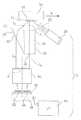
本発明によると、光学的可変マーキングの光学特性を測定するためのデバイス5は、図1で概略的に例示される。検査すべき物体10、例えば医薬品のための包装、またはあるセキュリティ特徴(セキュリティ機能)を光学的可変マーキングの形で有する銀行券(紙幣)は、例えば自動包装システムのコンベヤーベルトを使用することによって、レンズ40によって定義される光学軸Oに実質的に垂直である方向Vにデバイス5を過ぎて移動される。物体10は、それの前面12に印刷される光学的可変マーキング15を有する。マーキング15は、光学的可変インク(OVI)の使用によって物体10にあらかじめ印刷されていてもよい。マーキング15は、反射光の色または波長が観測または反射の角度の関数として変化することになるように、異なる光学的厚さおよび屈折率を持つ薄膜多層コーティングによって作られてもよい。 According to the invention, a device 5 for measuring the optical properties of an optically variable marking is schematically illustrated in FIG. An
例えば、マーキング15は、異なる方向で見るとき光の異なるスペクトル組成を形成するために、表面12への視角に応じて、それを照明光のある波長を異なる仕方で反射できるようにする特性を有してもよい。例えば、OVIは、物体10の前面12に実質的に垂直である視角α1(α1=0°、+/−5°)からは、マーキング15が原色PC、例えば緑色に見え、マーキング15が前面12に関して斜角、例えば角度α2から見られるときは、二次色SCが見えるような色シフト特性を有するように作ることができる。マーキング15のOVIはまた、原色、二次色および三次色、PC、SCおよびTCが、それぞれの視角またはより多くの角度から見え、色シフトが視角の連続的変化とともに連続的に変化するように作ることもできる。For example, the marking 15 has properties that allow it to reflect a certain wavelength of illumination light differently depending on the viewing angle to the
例えばマーキング15のOVIは、マーキング15から反射される光が、例えば物体10の前面12に実質的に垂直である角度α1=0°、+/−5°から始まる視角の増加とともに赤色から緑色に変化するように作ることができる。波長の関数としての反射率は、視角に応じて可変である。例えば反射率曲線は、ある波長で、例えば赤色については650nmでピークを有することもあり、視角に応じて、反射率曲線のピークは緑色については510nmに移動する。マーキング15の別の変形形態では、OVIは、異なる視角から見るとき、異なる偏光の光が放出されるように作られる。偏光は、観測角度の関数として変化する可能性があり、従って異なる観測角度が、異なる偏光を分析するために使用される。さらに、OVIでできている光学的可変層によって覆われるロゴ、テキストまたは絵が、視角とともに変化する可変透明度を有するようにマーキング15を作ることが可能である。それによって、ロゴは、もし1つの角度から見るならば隠れていることもあるが、しかし第2の角度から見るときは目に見える可能性がある。OVI材料の化学的および光学的特性ならびに印刷環境に応じて、角度α1≠0°が、原色PCを見るために使用されなければならないこともまたあり得る。For example, the OVI of the
物体10に印刷されるマーキング15は、ある情報を含み、デバイス5によって容易に分析できる特定のパターンまたは形状を含んでもよい。例えば、特殊文字、マトリックスコード、バーコード、画像などが、マーキング15として印刷されてもよい。照明デバイス20は、例えば白色発光ダイオード(LED)の使用によって、マーキング15上に光25を放出するために使用される。照明デバイス20は、画像センサがさらなる処理のために放出光を獲得することができるように、十分な光がマーキング15から反射されるように構成される。例として、照明は、LEDによって生成される光強度に応じて、1つまたは複数の白色LEDを使用する指向性光源、例えばEdmund(商標)高度照明高強度LEDスポットライトとすることができる。照明角度αillはまた、色シフト特性の角度に影響を及ぼすこともある。変形形態では、照明デバイス20は、光25によるマーキング15の照明の均一性を増加させるように、表面12の前の様々な場所に配置できる。広いスペクトルの白色光25は次いで、マーキング15から反射される。第1の光l1は、物体10の表面12から第1の角度で、図示される例では表面12に実質的に垂直である角度0°で反射される。第1の光l1は、第1の特性、例えば第1の原色(PC)、または第1の角度から見える第1のパターンもしくは偏光を有することができる。加えて、物体10の前面12に対して斜めである角度から、図示される例では約45°で見ると、第1の特性と異なる第2の特性を有する第2の光l2が反射される。第2の特性は、二次色(SC)、または第2の角度からは見えるが、しかし第1の角度からは見えない第2のパターンの放出である可能性もある。第1および第2の特性が、異なる色PCおよびSCである場合には、第1の光l1および第2の光l2は、これらの色PCおよびSCで放出されることになり、200nmから900nmの間の実質的に重ならない波長範囲、例えばそれのピークを650nmに有するPCの波長の関数としてのスペクトル組成、およびそれのピークを510nmに有するSCの波長の関数としてのスペクトル組成を有することになる。The marking 15 printed on the
デバイス5は、第2の光l2がプリズム30の前面31の方へ反射され、プリズム30の第1の部分32に入り、第1の部分32の後面36の方へ向けられるように構成される。プリズム30は、周囲の環境、すなわち空気の屈折率nenvと異なる屈折率nを有する。第2の屈折光l21は次いで、第2の光l2の伝播角度と異なる角度で、プリズム30の第1の部分32の後面36から出る。第2の屈折光l21はそれによって、それの方向を変え、プリズムに使用される材料に大きく依存するいくらかの色分散を有することもあるが、しかし波長のシフトは生じない。第2の屈折光l21は、レンズ40によって獲得され、マーキング15のパターン52は次いで、画像センサ50上の第1の場所に形成され、獲得される。同時に、第1の光l1は、プリズム30の前面31の方へ反射され、プリズム30の第2の部分34に入る。第1および第2の光l1およびl2は、物体10の前面12に関して異なる伝播角度を有する。図示される変形形態では、第1の光l1の角度は、光学軸Oに実質的に平行であり、物体10の前面12に実質的に垂直であり、レンズの方へ向けられ、一方l2の角度は、レンズに直接ぶつかるには大きすぎる。第1の光l1は次いで、第1の部分34の後面38の方へ伝播し、第1の光l1の伝播角度と実質的に同じ角度で第1の光l11として後面38から出る。好ましくは、第2の屈折光l21と第1の光l11との間の角度分離は10°を超えない。The device 5 is configured such that the second light12 is reflected towards the
プリズム30は、第2の屈折光l21もまたレンズ40の方へ向けられ、レンズ40によって画像センサ50の方へ案内されるように配置される。第1の光l11は次いで、レンズ40によって獲得され、マーキング15のパターン54は次いで、画像センサ50の第1の場所と重ならない第2の場所の第2の部分、画像センサ50の異なる場所によって獲得される。この配置は、第1および第2のパターン52および54を画像センサ50で同時に獲得することを可能にし、パターン52および54は、どんな追加のカメラまたは同期機構も必要とすることなく、第2の屈折光l21および第1の光l11によってそれぞれ形成される。これは、センサ50から獲得された単一画像での両方のパターン52および54にデジタル処理を適用することを可能にする。例えば同時獲得は、画像センサ50の同じ積分時間内にパターン52および54を獲得することを可能にする。The
プリズム30の使用は、光l1およびl2を反射するためにミラーを使用するのと比較して、OVIでできているマーキング15を検査するときにいくつかの利点を提示する。例えば、ミラーは通常、センサ50によって獲得される画像に直線歪みを導入し、その結果さらなる補正処理が、必要とされることもあり、マーキング15の第1および第2の特性の検出品質および精度は、強く低減される可能性がある。加えて、ミラーの使用は、追加の多重反射を導入する可能性があり、その結果デバイス5での要素からの多重反射と重なることなく、パターン52および54を画像センサ50の分離した領域に別々に投影することができないことになる。多重反射は、光が2つ以上のミラー間で2回以上反射されるときに生じる。追加の望ましくない二次反射はその結果、光の一次の望ましい反射によって生成される画像と干渉することもある。レンズ40およびプリズム30の使用は、光の伝播を変えるためにミラーに基づくシステムと比較すると直線歪みを実質的に低減することを可能にし、またある測定を妨げるまたは不可能にすることもあるミラーに基づくシステムに優るミラー間の二重反射を避けることができる実質的な利点を提示することも可能にする。The use of
画像センサ50の同じ積分時間中に異なる角度で反射された第1および第2の特性を有する異なる光についてのパターン52、54のこの同時獲得は、測定および分析目的のために追加の利点を提供する。画像センサ50、例えば電荷結合デバイス(CCD)または相補型金属酸化物半導体(CMOS)撮像センサの、例えば1μsから100msの範囲の特定の積分時間を所与とすると、パターン52および54を同時に獲得し、その後同じマーキング15から生じるパターン52および54を直接比較することは可能である。 This simultaneous acquisition of
変形形態では、三角形断面形状であるプリズム30の第1の部分32だけを使用することもまた可能であり、一方第2の部分34は存在せず、第1の光l1は別の光学媒体を通過しない。それによって、マーキング15から垂直に放出される第1の光l1は、レンズ40および画像センサ50によって直接獲得されることになる。プリズムの第1の部分32の前面31の部分は、それの幅が、例えば物体10の移動方向Vでマーキング15の幅よりも広いように配置される。In a variant, it is also possible to use only the
画像センサ50は次いで、第1および第2のパターン52および54の画像を獲得するために使用され、その画像はデジタル形式に変換できる。画像センサ50は、画像センサ50によって獲得される画像を読み出すように構成されるドライバーユニット56と結合される。例えば、すべてのドライバー、クロック信号発生器、供給および参照電圧(基準電圧)発生器、アナログデジタル変換器、タイミング信号発生器、メモリバッファーなどは、ドライバーユニット56の一部とすることができる。ドライバーユニット56それ自体は、画像センサ50によって獲得される画像についてデータおよび画像処理を行うことができる処理ユニット60に結合される。処理ユニット60は、パーソナルコンピュータ(PC)によって、または処理ユニット60、画像センサ50およびドライバーユニット56をすべて再結合させる知的カメラシステム、例としてCognex(商標)InSight 1400cによって実現でき、ハードウェアプロセッサおよびメモリを含むことができ、そのメモリは、命令がプロセッサで実行されるとき、様々なデータ処理、視覚化および通信機能を行うことができるコンピュータ可読命令を保存するように構成される。メモリは、揮発性もしくはFLASHメモリ、またはそれらの組合せとすることができる。加えて、処理ユニット60はまた、画像処理、特徴抽出、統計アルゴリズム、および較正アルゴリズム、その他などのデータ処理を行うことができるハードウェア符号化画像処理チップ、フィールドプログラマブルゲートアレイ(FPGA)、または複合プログラマブル論理回路(CPLD)を含んでもよい。例えば、ユニット60は、メディアンフィルタ処理、画像較正、背景画像センサ雑音較正、統計的画像分析、推定、ルックアップテーブル生成および管理、その他などの画像フィルタ処理を行ってもよい。 The
第1および第2の特性、例えば原色および二次色PC、SCをそれぞれ有するパターン52および54を表す獲得された画像データを使って処理ユニット60によってなされる典型的な測定は、データマトリックスコード、バーコードの読出し、色品質印刷検査、偏光パターンの分析、マーキングの幾何学的形状の検証などを含む。例えば、そのような測定は、もし色画像センサ50が使用されるならば、マーキング15が、正確に定義される色シフト特性を有する特殊なOVI型でできているかどうかを検証することを可能にする。例えば、処理ユニット60は、波長の関数としての第1および第2の光l11およびl21の両方についてのスペクトルのプロファイルを、処理ユニット60に保存される参照プロファイルと比較することができる。別の例として、異なる角度から見るときのマーキング15の可変透明度を考慮すると、パターン54は、光l11によって見える第1のロゴを示してもよく、一方パターン52は、光l21によって第1のロゴと異なる第2のロゴを示してもよい。Typical measurements made by the
図2は、図1で示されるようなデバイス5で行うことができる光学的可変マーキングの光学特性を測定するための方法のステップを表す図を示す。物体10は、マーキング15がレンズ40および画像センサ50の視野にあるように、光学的可変マーキング15の特性を測定するように構成されるデバイス5の前を通り、ステップS10で広いスペクトルの白色光を持つ照明デバイス20によって照らされる。次に、第1の光l1は、ステップS22で物体10の表面12から第1の角度でマーキング15から反射され、第2の光l2は、ステップS20で物体10の表面12から第2の角度でマーキング15から反射される。反射された第2の光l2は、プリズム30の第1の部分32の方へ放出され、ステップ30で第1の部分32で屈折されて、屈折された第2の光l21として退出する。同時に、示される図では、第1の光l1は、画像センサ50上に結像させるためのレンズ40以外のどんな他の光学媒体も通過しない。変形形態では、第1の光l1は、プリズム30の第2の部分34などの光学媒体を通って案内されてもよい。FIG. 2 shows a diagram representing the steps of a method for measuring the optical properties of an optically variable marking that can be performed with the device 5 as shown in FIG. The
次に、第2の屈折光l21および第1の光l1は、レンズ40の方へ伝播し、レンズ40によって画像センサ50上に結像されて、ステップS40で第2の屈折光l21および第1の光l1のパターン52および54をそれぞれ形成する。信号を画像センサユニット50またはドライバーユニット56に提供するトリガーステップS45は、パターン52および54の画像が獲得されるべき時を指示するために行われる。プリズム30の前面31への第1の光l1によるパターン54としてのマーキング15の投影が、プリズム30の第1の部分32の領域内に位置するとすぐに、トリガー信号は、センサユニット50による画像積分をトリガーすることができる。例えば、そのようなトリガーは、トリガーゾーンへの物体10の到着を検出する光バリアーによって、またはセンサユニット50それ自体によって、物体10の到着を検出するために高周波数で部分的画像を読み出すことによって実施されてもよい。次いで、これらのパターン52および54は、ステップS40で画像センサの同じ積分時間で同時に獲得され、デジタル画像に変換され、そのデジタル画像は、処理ユニット60に提出される。Next, the second refracted light l21 and the first light l1 propagate toward the
次のステップS50では、処理ユニット60は、獲得されたデジタル画像ならびに第1および第2の特性をそれぞれ有するパターン52および54を評価する。例えば、各パターン52、54についてある波長に関する色範囲および強度が、特定の波長λが振幅と比較される所定のパターンに対応するかどうかを検証するための色処理が行われてもよい。また、処理ユニット60は、画像についての特徴検出、画像分割または色分析が容易にできるように、RGB色情報を色相−彩度−明度(HSL)または色相−彩度−値(HSV)色情報に変換してもよい。そのような色処理は、他の処理アルゴリズム、例えばバーコードまたはマトリックスコードの読出し、マーキング15のある寸法の測定、ある印刷情報の読出し、シンボルまたはロゴの識別などと組み合わせることができる。別の例として、異なる特性を有するパターン52および54へのパターン照合が行われてもよい。 In a next step S50, the
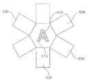
次に、図3Aおよび図3Bでは、光学的可変マーキングの光学特性を測定するためのデバイス105の概略断面図および正面図が描写される。検査すべき物体110は、デバイス105の方を向く表面112上に光学的可変マーキング115を有し、コンベヤーベルト117によってデバイス105の視野を過ぎて移動される。デバイス105は、耐スクラッチ性石英ガラスまたは普通のガラスで作ることができる前部窓194を備えるケーシング190、例えばアルミニウムまたはポリマー側面、およびその中に配置されたコネクタ180、181を有する後部密閉部192で構成される。コネクタ180は、カメラ150によって配送されるデジタル画像のさらなる処理のための処理ユニット160にカメラ150を接続する高速画像データ転送バス182とすることができる。この適用のための例となるカメラ150は、640×480画素の解像度を持つGenie(商標)C640−1/3である可能性もあり、CマウントまたはCSマウントのレンズ接合面を有する。カメラ150は、ケーシング190の側壁に保持用ブラケット156を使って取り付けられる。さらに、レンズ140は、ケーシング190にブラケット142を使って取り付けられ、カメラ150のCマウントまたはCSマウント接合面に結合される。この適用に使用される可能性がある典型的なレンズ140は、Computar(商標)またはFujinon(商標)レンズであってもよい。ブラケット142は、レンズ140を安定させるのに役立つが、しかしまたレンズ140の焦点をある位置に固定するのにも役立つ。 Next, in FIGS. 3A and 3B, schematic cross-sectional and front views of the
さらに、プリズム130は、ケーシング190の内部に配置され、前部窓194と直接接触しており、取付け要素139は、プリズム130を固定位置に取り付けるためにケーシング190中に配置される。前部窓194およびプリズム130はまた、1つの単体物から作ることもできる。プリズムは、シリカ、サファイア、ポリカーボネート、ポリメチルメタクリレート(PMMA)のようなポリマーなどの材料から作ることができる。例となるプリズムは、Edmund(商標)NT43−672、12.7mm×12.7mm×21.9mmのようなリトロー(Littrow)分散プリズムである可能性もある。プリズム130は、ケーシング内部幅ほど広くなく、その結果照明デバイス120は、プリズム130の隣に配置でき、また前部窓194の方を向いてもいる。変形形態では、照明デバイス120はまた、前部窓194での反射を避けるためにケーシング120の外部に配置することもできる。分離シールド127は、プリズム130の内部でマーキング115からの第1および第2の光l1およびl2と干渉することになる寄生光が、プリズム130の側壁を通って入ることを避けるために、照明部分をプリズム130から光学的に分離するように配置される。ケーシングの内部は、黒色塗料でまたは非常に低い反射特性を有するコーティングで覆われてもよく、スクリーンが、プリズムの視野を低減するためにプリズム130に追加されてもよい。これらのスクリーンは、光l2およびl1のための入射ゾーンを定義するためにプリズム130の前面131に適用されてもよい。照明デバイス120は、反射体122と、電力供給ユニット126に接続される発光ダイオード(LED)またはハロゲン球などの発光素子124とを含むことができる。例えば、照明デバイス120は、Edmund(商標)高度照明高強度LEDスポットライトである可能性もある。照明デバイス120は、ケーシング190の内部に配置でき、照明源120のストロボスコープ照明のための電力制御、トリガー信号を提供することができる制御ユニット170に接続される。トリガー検出ユニット172、例えば光バリアー172もまた、制御ユニット170と接続でき、その結果カメラ150による画像取得をトリガーするためのおよびストロボスコープ照明120のためのトリガー信号が提供できる。制御ユニット170それ自体は、ポート181によって外部電力供給装置161と接続でき、またトリガー信号ならびに例えば電力供給装置および温度105を管理するための他の制御情報を提供するまたは受け取るために処理ユニット160とも接続できる。Further, the
図3Bは、ケーシング190の中で左側に位置するプリズム130の第1および第2の部分132、134を示すデバイス105の正面図を描写する。分離シールド127は、ケーシング190の右側の領域に位置し、発光素子124および反射体122を備える照明デバイス120を取り囲む。さらに、プリズム130および分離シールド127をケーシング190の中の定義された位置に収める取付け要素139もまた、透明な前部窓194を通って示される。 FIG. 3B depicts a front view of
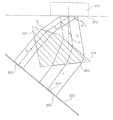
図4は、画像獲得の可能性のある時間事例での光検出デバイス5の要素およびマーキング15を備える物体10についての寸法および幾何学的関係の概略図を示す。寸法および幾何学的関係は主に、マーキング15のサイズおよびOVIの特性によって決定される。例えば、使用されるOVIおよびマーキング15の多層構造に応じて、マーキングの異なる特性は、理想的な角度α2を決定することになる。加えて、照明の角度αillは、理想的な角度α2に影響を及ぼすことになる。角度α2は通常、直接反射を避けるためにαillよりも大きく選択される。例えば、第1および第2の特性が、原色および二次色PC、SCである場合には、角度α2はSCが容易に検出でき、理想的には角度α1=0°から見ることができるPCと明らかに区別できるように、かつ斜角の下でマーキング15の可読性の幾何学的考察に基づいて決定されることになる。寸法および幾何学的関係は、第2の屈折光l21および第1の光l11が、レンズ40を用いて画像センサ50の方へ伝播することになるように設定される。好ましくは、l11とl21との間の角度分離は、パターン52およびパターン54の中心間の距離Gを所与として、パターン52および54が互いに十分に間隔をあけられ、その結果それらが画像センサ50のそれぞれの領域に投影されるように選択される。画像センサ50は、レンズ40のない図4では不釣り合いに示され、画像センサ50の幅は通常、BおよびFよりも小さいことに留意されたい。FIG. 4 shows a schematic diagram of the dimensions and geometric relationships for the
マーキング15は、定義された幅Lを有し、プリズム30の第1の部分32の前面は、幅Bを有し、プリズム30の第2の部分34の前面は幅Fを有する。さらに、物体10の前面12とプリズム30の前面31との間の距離は、表面12に垂直な方向にDである。幅Eは、センサ50による画像獲得の時のマーキング15の前方エッジとプリズム30の第1の部分32の右側エッジとの間の横方向距離を表す。図示される変形形態では、プリズムの第1の部分32は、直角三角形の断面形状を有する。さらに、画像センサ50およびレンズ40(図1)の光学軸Oはまた、物体10の前面12に垂直でもある。照明デバイス20は、マーキング15からプリズム30の前面31への光の反射を妨害しないように右側に配置され、光学軸Oに関して角度αillを照らすように配置される。第2の反射光l2は、角度α2でマーキング15から放出され、前面31に垂直な軸に関して角度φ1でプリズム30の前面31に入る。図示される変形形態では、前面31に垂直な軸は、光学軸と平行である。The marking 15 has a defined width L, the front surface of the
次に、第2の反射光l2は、プリズム30の第1の部分32の内部では、前面31に垂直な軸に関して角度φ2で、かつ前面31それ自体に関して角度β1で伝播し、プリズム30の第1の部分32の後面36に、後面36に垂直な軸Aに関して角度φ3で、かつ後面36それ自体に関して角度β2でぶつかる。第2の屈折光l21は、プリズム30から出るときそれの方位角を変え、後面36に垂直な軸Aに関して角度φ4を有する。さらに、プリズム30の第1の部分32の傾斜角はβである。図示される変形形態では、プリズム30のβおよび寸法は、第2の屈折光l21および第1の光l11が、レンズ40および画像センサ50の方へ伝播するように選択される。例えば文字Aを提示する、画像センサ50に形成されるパターン52および54は、プリズム30の後面36および38からそれぞれ投影される。Next, the second reflected light l2 propagates within the
デバイス5、105をそれの要素とともに設計するとき、次の関係が見いだされた。直角三角形の側部を形成する屈折率nを有するプリズム30の第1の部分32の前面の幅Bは好ましくは、マーキングの幅Lの1.2倍から3倍の間の範囲の、より好ましくは幅Lの1.5から2倍の間の範囲の倍数である。幅Bは、マーキング15の幾何学的形状を2つの完全なパターン52および54によって調べる必要がない場合には、幅Lよりも小さくすることができる。さらに、画像獲得の時の距離Eは、それが幅Lの0.1倍からLの0.5倍に至るまでの間の範囲、より好ましくはLの0.2倍から幅Lの0.3倍の間の範囲にあるようなものである。幅Lは一般に、1mmよりも大きい。第2の反射光l2の観測角α2は、マーキング15に使用されるOVIの種類に従って選択され、40°から85°の範囲にあり、第1の光l1の観測角α1は約0°である。図示される変形形態では、角度α2は約45°である。これらのパラメーターに基づくと、好ましい距離Dは次の方程式[1]
さらに、プリズム30の三角形の第1の部分32に使用されるべき角度βは、次の[3]の通りに定義される。
これらの方程式[1]、[2]、および[3]は、β+β1+β2=180°という事実に基づいており、スネル(Snell)の法則[4]および[5]を与える。
さらに、前面31が光学軸Oに垂直である図4で示される配置では、次の方程式[6]もまた、当てはまる。
さらに、画像センサ50の視野の幅Wは、それがプリズム30の後面36から第2の屈折光l21によって放出されるパターン52、およびプリズム30の後面38から第1の光l11によって放出されるパターン54の両方をカバーするように配置される。この配置は、投影のための対応するレンズ40と一緒に適正なサイズを持つ画像センサ50を有することによって達成される。Further, the width W of the field of view of the
図5は、光学的可変マーキングの光学特性を測定するためのデバイス205の変形形態の概略断面図を描写し、ここでは異なる偏光フィルタ282、285は、軸対称に反対の角度α2で両方とも放出される第2の反射光l21およびl22をフィルタ処理するために使用される。フィルタ282、285は、第2の反射光l21およびl22が、フィルタ282、285を通過後、例えば角度α2で伝播する二次色SCの異なる偏光状態を有するように構成され、プリズム230の前面231上に膜または層として適用できる。変形形態ではこれらのフィルタは、前面231と接触することなくプリズム230の前に、またはプリズム230の後ろでプリズム230と画像センサ250との間に、例えばレンズ(図示されず)のところに配置できる。デバイス205は、画像が画像センサ250によって獲得され、物体210がレンズの光学軸Oに沿ったプリズム230の軸対称中心線によって定義される中心に実質的に位置する時間事例で描写される。物体210上のマーキング215は、第2の光を角度α2で両側の方へ互いに対称的に放出する。プリズム230は、特殊な台形断面形状を有し、両方の三角形の外側部分232および236は傾斜角βを有する。斜めの後面237および239は、パターン252および256を画像センサ250上に形成することになる光を放出することになる。プリズムの中央部分234はまた、省略される可能性もあり、その結果原色PCのパターン254は、マーキング215から直接獲得され、プリズム部分232および236は、三角形断面形状を有する2つの別個のプリズムを形成する。この配置は、2つの偏光フィルタ282、285が対応する光学経路に挿入されるとき、90°だけシフトする異なる偏光、例えば左偏光LPおよび右偏光RPを持つ第2の特性、例えば二次色またはある偏光を有する第2の光l21およびl22の2つのパターン252および256を作成することを可能にする。Figure 5 depicts a schematic cross-sectional view of a variant of the
プリズム230の対称的幾何形状を使ってマーキング215からの光放出から生成されるが、しかしフィルタ282、285によって生成される異なる偏光をそれぞれ有する2つの実質的に同一のパターン252および256の生成は、OVIの液晶ポリマーの性質を分析し、それが元のまたは改ざんされたマーキング215であるかを検証するのに役立つことができる。 The generation of two substantially
図6は、光学的可変マーキングの光学特性を測定するためのデバイス305の変形形態の概略断面図を描写し、例えばここではマーキング315の3つの異なる特性が、検出されなければならない。例えば、マーキング315は、物体310上のマーキング315から反射される原色、二次色および三次色PC、SC、およびTCを生成する可能性がある。この場合もやはり、デバイス305は、画像が画像センサ350によって獲得され、物体310が実質的にプリズム330の中央部分334の中心に位置する時間事例で描写される。マーキング315は、原色PCが物体310の表面312から垂直に反射され、二次色SCが角度α21によって反射され、三次色TCが物体の前面312から離れて角度α22によって反射されるようなOVIを備えて配置される。図示される例では、α21は約42°であり、α22は約65°である。プリズム330は、異なる傾斜角β21およびβ22をそれぞれ有する2つの三角形部分332および336で形成される。角度β21は、方程式[2]を使って決定できるが、三角形部分336の角度β22は、三次色の伝播角度α22に基づいて、同等の方程式を使って決定される。パターン352、354および356は、プリズム330の後面337、338および339から放出された原色、二次色および三次色PC、SC、およびTCの各々について画像センサ350上に形成される。プリズムの中央部分334はまた、省略される可能性もあり、その結果原色PCのパターン354は、レンズまたは保護ガラス(図示されず)以外の光学媒体を通過することなくマーキング315から直接獲得され、プリズム部分332および336は、三角形断面形状を有する2つの別個のプリズムを形成する可能性がある。この場合もやはり、画像センサ350およびレンズ(図示されず)を含む光学システムは、それの視野がセンサ350の同じ積分時間に3つのパターン352、354および356をすべて獲得できるように配置される。FIG. 6 depicts a schematic cross-sectional view of a variation of the
図7A、図7Bおよび図7Cは、画像センサによって獲得された画像を使って光学的可変マーキングの光学特性を測定するように構成されるデバイスのためのプリズムの実現の様々な変化を示す。これらのプリズムの使用の1つの目標は、画像センサの1つの単一積分時間で、色、偏光、形状、パターン、可変透明度などに関係する様々な特性が、単一の獲得画像内で測定できるように、OVIでできているマーキングから反射される光をカメラの単一画像センサ50に向け直すことである。マーキング415の異なる特性が、色シフト効果に起因して異なる色である場合には、本デバイスの別の目標は、マーキング415から反射されるすべての異なる色をレンズおよび画像センサの方へ画像センサの上面に垂直に伝播させることである。例えば、図7Aは、被検査物体の前面から垂直に見たプリズム430を示し、ここではプリズム430の左および右部分436、439は、左および右偏光フィルタを通過した光を屈折させて、左偏光LPおよび右偏光RPを生成するために使用される。加えて、下方部分432は、物体のマーキング415の二次色SCを屈折させるために使用される。中央部分438は、原色PCを画像センサ(図示されず)に渡すために使用される。 7A, 7B and 7C illustrate various changes in the implementation of a prism for a device configured to measure the optical properties of an optically variable marking using images acquired by an image sensor. One goal of using these prisms is a single integration time of the image sensor, and various properties related to color, polarization, shape, pattern, variable transparency, etc. can be measured in a single acquired image. Thus, the light reflected from the marking made of OVI is redirected to the
別の変形形態は、図7Bで示され、ここではプリズム530の左および右部分536、539は、図5に関して説明されるように配置される可能性がある左および右偏光フィルタを通過した光を屈折させて、左偏光LPおよび右偏光RPを生成するために使用される。加えて、下方部分および上方部分532、534は、物体のマーキング515の二次色SCおよび三次色TCを屈折させて、SCおよびTCを画像センサの方へ向けるために使用できる。中央部分538は、原色PCを画像センサ(図示されず)に渡すために使用される。加えて、図7Cは、プリズム630を描写し、ここでは中央部分は、六角形断面形状を有し、突出プリズム部分(protruding prism portions)636は、六角形状の周りに配置される。突出プリズム部分636は、中央部分638および6つの突出部分636の使用によって単一のマーキング615から放出される異なる色の7つの異なるパターンを屈折させて、例えば異なる偏光および色を投影するように構成できる。突出部分は、マーキング615からの異なる色を屈折させるために、図6で示されるように、異なる角度を持つ三角形状を有することができる。 Another variation is shown in FIG. 7B, where the left and
図8は、光学的可変マーキング715の光学特性を測定するためのデバイス705の別の変形形態の概略断面図を描写する。図示される変形形態では、画像センサ750の上面751は、第2の特性を持つ光l2を放出する物体710の上面712に平行ではないが、しかし画像センサ750およびレンズ(図示されず)は、角度α2で放出される観測光l2によって形成される軸と垂直に配置される。第1の特性を有する第1の光l1は、物体710の表面712から角度α1=0°で垂直に放出され、三角形断面形状を有するプリズム730の前面731に入る。光l2は次いで、プリズムの後面736から出て、第1の特性を有する光l12として画像センサの方へ垂直に向け直される。照明デバイス720は、広いスペクトルの白色光をある照明角度αillで投影し、プリズム730および画像センサ750の方への光l1およびl2の反射を妨害しないように配置される。FIG. 8 depicts a schematic cross-sectional view of another variation of
図9は、光学的可変マーキング815の光学特性を測定するためのデバイス805の別の変形形態の概略断面図を描写し、ここでは第1および第2の特性をそれぞれ有する第1および第2の光l1およびl2の伝播角度α1およびα2のどれも、画像センサ850の上面851に垂直でない。そのような構成では、プリズム830の2つの部分832および834は、光l11およびl21としてレンズ(図示されず)および画像センサ850の方へ向けられ、画像センサ850の上面に垂直にぶつかるように両方の光l1およびl2を屈折させるために使用されなければならない。この変形形態は、プリズム830の内部で光l1およびl2のための非常に似た伝播経路長を有するプリズム830を設計するために使用でき、その結果パターン852および854は、プリズム830から生じる似た形状およびサイズを有することになる。FIG. 9 depicts a schematic cross-sectional view of another variation of device 805 for measuring the optical properties of optically
本発明は本明細書で、特定の実施形態を参照して述べられたけれども、これらの実施形態は、本発明の原理および適用の実例となるにすぎないと理解すべきである。従って、多数の変更が、実例となる実施形態になされてもよく、他の配置が、添付のクレームによって定義されるような本発明の精神および範囲から逸脱することなく考案されてもよいと理解すべきである。 Although the invention herein has been described with reference to particular embodiments, it is to be understood that these embodiments are merely illustrative of the principles and applications of the present invention. Accordingly, it will be understood that numerous modifications may be made to the illustrative embodiments and that other arrangements may be devised without departing from the spirit and scope of the invention as defined by the appended claims. Should.
Claims (13)
Translated fromJapanese前記マーキングによって第1の視角で反射される第1の光および前記マーキングによって第2の視角で反射される第2の光を形成するように前記光学的可変マーキングを照らすステップであって、前記第1および第2の光は、前記光学的可変マーキングの結果として異なるスペクトル組成を有するステップと、
反射した前記第2の光を光学センサの方へ向け直すように、反射した前記第2の光を、光学ユニットを通して屈折させるステップと、
前記第1の光および屈折した前記第2の光を前記光学センサで同時に獲得するステップと、
獲得した前記第1および第2の光に基づいて前記光学的可変マーキングの光学特性を決定するステップとを含む方法。In a method for measuring optical properties of an optically variable marking applied to an object,
Illuminating the optically variable marking to form first light reflected by the marking at a first viewing angle and second light reflected by the marking at a second viewing angle, the first variable The first and second lights have different spectral compositions as a result of the optically variable marking;
Refracting the reflected second light through an optical unit to redirect the reflected second light toward the optical sensor;
Simultaneously acquiring the first light and the refracted second light with the optical sensor;
Determining optical properties of the optically variable marking based on the acquired first and second light.
獲得した前記第1および第2の光の色特性を測定するステップを含む請求項1に記載の方法。The optical sensor includes a color sensor, and the step of determining the optical characteristic further includes
The method of claim 1, comprising measuring color characteristics of the acquired first and second light.
前記マーキングによって第1の視角で反射される第1の光および前記マーキングによって第2の視角で反射される第2の光を形成するように前記光学的可変マーキングを照らす動作が可能な光源であって、前記第1および第2の光は、前記光学的可変マーキングの結果として異なるスペクトル組成を有する前記光源と、
反射した前記第2の光を向け直すように、反射した前記第2の光を屈折させる動作が可能なプリズムと、
前記第1の光および屈折した(向け直された)前記第2の光を同時に獲得する動作が可能な光学センサと、
獲得した前記第1の光および屈折した前記第2の光に基づいて前記光学的可変マーキングの光学特性を決定する動作が可能な処理ユニットとを含むデバイス。In a device configured to measure properties of an optically variable marking applied to an object,
A light source capable of illuminating the optically variable marking to form first light reflected by the marking at a first viewing angle and second light reflected by the marking at a second viewing angle. The first and second light beams having different spectral compositions as a result of the optically variable marking;
A prism capable of refracting the reflected second light so as to redirect the reflected second light;
An optical sensor operable to simultaneously acquire the first light and the refracted (redirected) second light;
A processing unit operable to determine an optical characteristic of the optically variable marking based on the acquired first light and refracted second light.
反射した前記第1の光を屈折させる動作が可能な第1の部分と、
反射した前記第2の光を屈折させる動作が可能な第2の部分とを含み、
前記プリズムの前記第1および第2の部分は、互いに異なる屈折特性を有する請求項6に記載のデバイス。The prism further includes:
A first portion capable of refracting the reflected first light; and
A second portion operable to refract the reflected second light,
The device of claim 6, wherein the first and second portions of the prism have different refractive properties.
前記プリズムはさらに、反射された前記第3の光を屈折させる動作が可能な第3の部分を含み、
前記プリズムの前記第1、第2および第3の部分は、互いに異なる屈折特性を有する請求項9に記載のデバイス。The light source is further operable to illuminate the optically variable marking to form a third light that is reflected at a third viewing angle by the optically variable marking, wherein the third viewing angle is the first viewing angle. Unlike the first and second viewing angles,
The prism further includes a third portion operable to refract the reflected third light,
The device of claim 9, wherein the first, second and third portions of the prism have different refractive properties.
前記マーキングによって第1の視角で反射される第1の光および前記マーキングによって第2の視角で反射される第2の光を形成するように前記光学的可変マーキングを照らす動作が可能な光源であって、前記第1および第2の光は、前記光学的可変マーキングの結果として異なるスペクトル組成を有する前記光源と、
反射した前記第2の光を前記第2の視角と異なる方向に屈折させて、向け直された第2の光を形成する動作が可能な光学手段と、
反射した前記第1の光および向け直された前記第2の光を同時に光学センサで獲得する動作が可能な光学センサと、
前記光学センサに接続され、前記光学センサから受け取る信号に基づいて前記光学的可変マーキングの光学特性を決定する動作が可能な処理ユニットとを含むデバイス。In a device for measuring the optical properties of an optically variable marking applied to an object,
A light source capable of illuminating the optically variable marking to form first light reflected by the marking at a first viewing angle and second light reflected by the marking at a second viewing angle. The first and second light beams having different spectral compositions as a result of the optically variable marking;
Optical means capable of refracting the reflected second light in a direction different from the second viewing angle to form redirected second light;
An optical sensor operable to simultaneously capture the reflected first light and the redirected second light with an optical sensor;
A processing unit connected to the optical sensor and operable to determine an optical characteristic of the optically variable marking based on a signal received from the optical sensor.
Applications Claiming Priority (9)
| Application Number | Priority Date | Filing Date | Title |
|---|---|---|---|
| US35965410P | 2010-06-29 | 2010-06-29 | |
| EP10167697 | 2010-06-29 | ||
| US61/359,654 | 2010-06-29 | ||
| EP10167697.1 | 2010-06-29 | ||
| US37022810P | 2010-08-03 | 2010-08-03 | |
| US61/370,228 | 2010-08-03 | ||
| EP10171741.1 | 2010-08-03 | ||
| EP10171741 | 2010-08-03 | ||
| PCT/EP2011/060955WO2012001077A1 (en) | 2010-06-29 | 2011-06-29 | Method and device for measuring optical properties of an optically variable marking applied to an object |
Publications (1)
| Publication Number | Publication Date |
|---|---|
| JP2013531307Atrue JP2013531307A (en) | 2013-08-01 |
Family
ID=45352253
Family Applications (1)
| Application Number | Title | Priority Date | Filing Date |
|---|---|---|---|
| JP2013517285APendingJP2013531307A (en) | 2010-06-29 | 2011-06-29 | Method and device for measuring optical properties of optically variable markings applied to objects |
Country Status (10)
| Country | Link |
|---|---|
| US (1) | US8467038B2 (en) |
| EP (1) | EP2588992B1 (en) |
| JP (1) | JP2013531307A (en) |
| CN (1) | CN102971744B (en) |
| AU (1) | AU2011273522B2 (en) |
| CA (1) | CA2798438A1 (en) |
| EA (1) | EA201291288A1 (en) |
| MX (1) | MX2012012818A (en) |
| MY (1) | MY161574A (en) |
| WO (1) | WO2012001077A1 (en) |
Cited By (1)
| Publication number | Priority date | Publication date | Assignee | Title |
|---|---|---|---|---|
| JP2015169964A (en)* | 2014-03-04 | 2015-09-28 | 株式会社東芝 | Inspection apparatus |
Families Citing this family (16)
| Publication number | Priority date | Publication date | Assignee | Title |
|---|---|---|---|---|
| WO2013126286A1 (en)* | 2012-02-21 | 2013-08-29 | General Electric Company | System and method for segmenting image data to identify a character-of-interest |
| CN104021363B (en)* | 2013-02-28 | 2018-04-27 | 联想(北京)有限公司 | A kind of object information recognition methods and system |
| ES2655504T3 (en)* | 2013-05-01 | 2018-02-20 | Sicpa Holding Sa | Security elements that have a dynamic visual movement |
| TWI490526B (en)* | 2013-07-05 | 2015-07-01 | Pixart Imaging Inc | Optical sensing module and electronical apparatus having the same |
| DE102013216308A1 (en)* | 2013-08-16 | 2015-02-19 | Bundesdruckerei Gmbh | Method and device for checking a security element of a security document |
| MY176665A (en)* | 2013-10-11 | 2020-08-19 | Sicpa Holding Sa | Hand-held device and method for authenticating a marking |
| US9033237B1 (en) | 2013-10-26 | 2015-05-19 | Symbol Technologies, Inc. | Decoding DPM indicia with polarized illumination |
| JP6638968B2 (en) | 2015-01-30 | 2020-02-05 | シクパ ホルディング ソシエテ アノニムSicpa Holding Sa | Simultaneous authentication of security article and security article user identification |
| JP6677390B2 (en) | 2015-01-30 | 2020-04-08 | シクパ ホルディング ソシエテ アノニムSicpa Holding Sa | Simultaneous authentication of security article and security article user identification |
| CN107438851B (en) | 2015-04-10 | 2021-09-28 | 锡克拜控股有限公司 | Mobile portable device for authenticating a security article and method of operating a portable authentication device |
| US11908122B2 (en) | 2017-04-26 | 2024-02-20 | Sensors Incorporated | System and method for performing production line product identification |
| US10198653B2 (en)* | 2017-04-26 | 2019-02-05 | Sensors Incorporated | System and method for performing production line product identification |
| FR3078582B1 (en)* | 2018-03-05 | 2021-06-18 | Hid Global Cid Sas | PROCESS FOR CONSTRUCTING A SECURITY IMAGE BY MULTIPLEXING COLOR IMAGES |
| US10513400B1 (en) | 2018-05-31 | 2019-12-24 | Ashot Mesropyan | Method and system of real-time analysis and marking of a target surface using a digital camera coupled marking device |
| US10915719B2 (en)* | 2019-03-04 | 2021-02-09 | Datalogic IP Tech S.R.L | Indicia capture with angled FOV in direct part marking |
| CN114386552B (en)* | 2021-12-28 | 2024-03-15 | 阿依瓦(北京)技术有限公司 | Bar code generating and reading method and device and computer readable storage medium |
Citations (2)
| Publication number | Priority date | Publication date | Assignee | Title |
|---|---|---|---|---|
| JPH0962894A (en)* | 1995-08-28 | 1997-03-07 | Dainippon Printing Co Ltd | Method and device for reading printed matter |
| JP2008151642A (en)* | 2006-12-18 | 2008-07-03 | Toyota Motor Corp | Color measuring device |
Family Cites Families (5)
| Publication number | Priority date | Publication date | Assignee | Title |
|---|---|---|---|---|
| AU695151B2 (en)* | 1994-10-27 | 1998-08-06 | Flex Products, Inc. | Viewing device and method for ascertaining simultaneously optical color shift characteristics of an optically variable device |
| CH693693A5 (en)* | 1997-06-06 | 2003-12-15 | Ovd Kinegram Ag | An apparatus for detecting optical diffraction markings. |
| US7360705B2 (en)* | 2005-07-14 | 2008-04-22 | Intermec Ip Corp. | Apparatus and method for reading machine-readable symbols |
| US7719675B2 (en)* | 2006-02-28 | 2010-05-18 | Applied Extrusion Technologies, Inc. | Method for optical characterization and evaluation of optically variable devices and media |
| CA2684789A1 (en)* | 2007-04-24 | 2008-10-30 | Sicpa Holding Sa | Method of marking a document or item; method and device for identifying the marked document or item; use of circular polarizing particles |
- 2011
- 2011-06-29MXMX2012012818Apatent/MX2012012818A/enactiveIP Right Grant
- 2011-06-29AUAU2011273522Apatent/AU2011273522B2/ennot_activeExpired - Fee Related
- 2011-06-29CACA2798438Apatent/CA2798438A1/ennot_activeAbandoned
- 2011-06-29EAEA201291288Apatent/EA201291288A1/enunknown
- 2011-06-29EPEP11728014.9Apatent/EP2588992B1/enactiveActive
- 2011-06-29WOPCT/EP2011/060955patent/WO2012001077A1/enactiveApplication Filing
- 2011-06-29MYMYPI2012005164Apatent/MY161574A/enunknown
- 2011-06-29CNCN201180032665.5Apatent/CN102971744B/enactiveActive
- 2011-06-29JPJP2013517285Apatent/JP2013531307A/enactivePending
- 2011-06-29USUS13/172,445patent/US8467038B2/enactiveActive
Patent Citations (2)
| Publication number | Priority date | Publication date | Assignee | Title |
|---|---|---|---|---|
| JPH0962894A (en)* | 1995-08-28 | 1997-03-07 | Dainippon Printing Co Ltd | Method and device for reading printed matter |
| JP2008151642A (en)* | 2006-12-18 | 2008-07-03 | Toyota Motor Corp | Color measuring device |
Cited By (1)
| Publication number | Priority date | Publication date | Assignee | Title |
|---|---|---|---|---|
| JP2015169964A (en)* | 2014-03-04 | 2015-09-28 | 株式会社東芝 | Inspection apparatus |
Also Published As
| Publication number | Publication date |
|---|---|
| EP2588992A1 (en) | 2013-05-08 |
| US20110317150A1 (en) | 2011-12-29 |
| US8467038B2 (en) | 2013-06-18 |
| CA2798438A1 (en) | 2012-01-05 |
| CN102971744B (en) | 2015-07-01 |
| WO2012001077A1 (en) | 2012-01-05 |
| MX2012012818A (en) | 2013-01-24 |
| EA201291288A1 (en) | 2013-06-28 |
| CN102971744A (en) | 2013-03-13 |
| MY161574A (en) | 2017-04-28 |
| AU2011273522B2 (en) | 2014-04-10 |
| EP2588992B1 (en) | 2017-02-08 |
| AU2011273522A1 (en) | 2012-11-15 |
| HK1180810A1 (en) | 2013-10-25 |
Similar Documents
| Publication | Publication Date | Title |
|---|---|---|
| EP2588992B1 (en) | Method and device for measuring optical properties of an optically variable marking applied to an object | |
| US10732102B2 (en) | Optical test apparatus and optical test method | |
| US7626709B2 (en) | Device for examining the optical properties of surfaces | |
| RU2665329C2 (en) | Method and device for observing and analysing optical singularities in glass vessels | |
| US20110310244A1 (en) | System and method for detecting a defect of a substrate | |
| KR100996335B1 (en) | Apparatus and method for checking inconsistencies in complex structures | |
| US11847853B2 (en) | Device for optical imaging of features of a hand | |
| JP5471477B2 (en) | Thread inspection equipment | |
| KR20160004099A (en) | Defect inspecting apparatus | |
| US20070024846A1 (en) | Device for Dark Field Illumination and Method for Optically Scanning of Object | |
| US9194810B2 (en) | Method and device for the detection of surface defects of a component | |
| KR101006983B1 (en) | Panel inspection device | |
| KR101658700B1 (en) | Optics Apparatus for Inspecting Surface of Panel and Method for Inspecting Surface | |
| AU2004241493A1 (en) | Device for checking banknotes | |
| CN213813329U (en) | Body check out test set | |
| RU69634U1 (en) | DEVICE FOR DETECTION AND CLASSIFICATION OF DEFECTS OF OPTICAL OBJECTS (OPTIONS) | |
| HK1180810B (en) | Method and device for measuring optical properties of an optically variable marking applied to an object | |
| JP7300152B2 (en) | Optical inspection device | |
| EP1139090A2 (en) | Leaded integrated circuit inspection system | |
| JP2005180939A (en) | Optical apparatus, inspection device and inspection method | |
| CN210572012U (en) | Coaxial light source device for industrial detection | |
| TWM421499U (en) | Optical inspection system | |
| JP2025144166A (en) | Optical device, optical inspection system, object imaging method, and object imaging program | |
| CN115616607A (en) | Imaging equipment, lidar and its receiving system | |
| JPH09280824A (en) | Alignment checking device |
Legal Events
| Date | Code | Title | Description |
|---|---|---|---|
| RD03 | Notification of appointment of power of attorney | Free format text:JAPANESE INTERMEDIATE CODE: A7423 Effective date:20140306 | |
| RD04 | Notification of resignation of power of attorney | Free format text:JAPANESE INTERMEDIATE CODE: A7424 Effective date:20140314 | |
| A621 | Written request for application examination | Free format text:JAPANESE INTERMEDIATE CODE: A621 Effective date:20140616 | |
| A977 | Report on retrieval | Free format text:JAPANESE INTERMEDIATE CODE: A971007 Effective date:20150317 | |
| A131 | Notification of reasons for refusal | Free format text:JAPANESE INTERMEDIATE CODE: A131 Effective date:20150421 | |
| A601 | Written request for extension of time | Free format text:JAPANESE INTERMEDIATE CODE: A601 Effective date:20150707 | |
| A521 | Request for written amendment filed | Free format text:JAPANESE INTERMEDIATE CODE: A523 Effective date:20151008 | |
| A02 | Decision of refusal | Free format text:JAPANESE INTERMEDIATE CODE: A02 Effective date:20160322 |