JP2013528079A - Prosthesis for partial replacement of tubular bone - Google Patents
Prosthesis for partial replacement of tubular boneDownload PDFInfo
- Publication number
- JP2013528079A JP2013528079AJP2013513586AJP2013513586AJP2013528079AJP 2013528079 AJP2013528079 AJP 2013528079AJP 2013513586 AJP2013513586 AJP 2013513586AJP 2013513586 AJP2013513586 AJP 2013513586AJP 2013528079 AJP2013528079 AJP 2013528079A
- Authority
- JP
- Japan
- Prior art keywords
- prosthesis
- shaft
- length
- prosthesis according
- adjustment
- Prior art date
- Legal status (The legal status is an assumption and is not a legal conclusion. Google has not performed a legal analysis and makes no representation as to the accuracy of the status listed.)
- Pending
Links
- 210000000988bone and boneAnatomy0.000titleclaimsabstractdescription15
- 230000007246mechanismEffects0.000claimsabstractdescription71
- 230000000295complement effectEffects0.000claimsdescription8
- 229910000684Cobalt-chromeInorganic materials0.000claimsdescription5
- 239000010952cobalt-chromeSubstances0.000claimsdescription5
- 239000000463materialSubstances0.000claimsdescription5
- 230000002093peripheral effectEffects0.000claimsdescription3
- WAIPAZQMEIHHTJ-UHFFFAOYSA-N[Cr].[Co]Chemical compound[Cr].[Co]WAIPAZQMEIHHTJ-UHFFFAOYSA-N0.000claimsdescription2
- 230000006835compressionEffects0.000claimsdescription2
- 238000007906compressionMethods0.000claimsdescription2
- 230000001681protective effectEffects0.000claims3
- 229920002994synthetic fiberPolymers0.000claims1
- 230000008901benefitEffects0.000description9
- 210000001519tissueAnatomy0.000description7
- 230000008878couplingEffects0.000description6
- 238000010168coupling processMethods0.000description6
- 238000005859coupling reactionMethods0.000description6
- 230000012010growthEffects0.000description6
- 230000008859changeEffects0.000description5
- 238000001356surgical procedureMethods0.000description5
- 238000002513implantationMethods0.000description4
- 230000007704transitionEffects0.000description4
- 238000006073displacement reactionMethods0.000description3
- 210000003127kneeAnatomy0.000description3
- 238000000034methodMethods0.000description3
- 230000008569processEffects0.000description3
- RTAQQCXQSZGOHL-UHFFFAOYSA-NTitaniumChemical compound[Ti]RTAQQCXQSZGOHL-UHFFFAOYSA-N0.000description2
- 230000002950deficientEffects0.000description2
- 239000007943implantSubstances0.000description2
- 238000003780insertionMethods0.000description2
- 230000037431insertionEffects0.000description2
- 230000007794irritationEffects0.000description2
- 210000003041ligamentAnatomy0.000description2
- 230000007774longtermEffects0.000description2
- 238000000926separation methodMethods0.000description2
- 230000008467tissue growthEffects0.000description2
- 239000010936titaniumSubstances0.000description2
- 229910052719titaniumInorganic materials0.000description2
- 210000000689upper legAnatomy0.000description2
- 206010028980NeoplasmDiseases0.000description1
- 208000002847Surgical WoundDiseases0.000description1
- 206010052428WoundDiseases0.000description1
- 208000027418Wounds and injuryDiseases0.000description1
- 230000009471actionEffects0.000description1
- 230000002411adverseEffects0.000description1
- 230000004520agglutinationEffects0.000description1
- 210000003484anatomyAnatomy0.000description1
- 238000002048anodisation reactionMethods0.000description1
- 230000008468bone growthEffects0.000description1
- 239000000316bone substituteSubstances0.000description1
- 210000002808connective tissueAnatomy0.000description1
- 238000010276constructionMethods0.000description1
- 230000001419dependent effectEffects0.000description1
- 210000002436femur neckAnatomy0.000description1
- 210000004349growth plateAnatomy0.000description1
- 230000010354integrationEffects0.000description1
- 210000000629knee jointAnatomy0.000description1
- 238000004519manufacturing processMethods0.000description1
- 230000003071parasitic effectEffects0.000description1
- 230000001575pathological effectEffects0.000description1
- 230000007170pathologyEffects0.000description1
- 238000005498polishingMethods0.000description1
- 238000011477surgical interventionMethods0.000description1
- 230000009466transformationEffects0.000description1
- 238000002054transplantationMethods0.000description1
Images


Classifications
- A—HUMAN NECESSITIES
- A61—MEDICAL OR VETERINARY SCIENCE; HYGIENE
- A61F—FILTERS IMPLANTABLE INTO BLOOD VESSELS; PROSTHESES; DEVICES PROVIDING PATENCY TO, OR PREVENTING COLLAPSING OF, TUBULAR STRUCTURES OF THE BODY, e.g. STENTS; ORTHOPAEDIC, NURSING OR CONTRACEPTIVE DEVICES; FOMENTATION; TREATMENT OR PROTECTION OF EYES OR EARS; BANDAGES, DRESSINGS OR ABSORBENT PADS; FIRST-AID KITS
- A61F2/00—Filters implantable into blood vessels; Prostheses, i.e. artificial substitutes or replacements for parts of the body; Appliances for connecting them with the body; Devices providing patency to, or preventing collapsing of, tubular structures of the body, e.g. stents
- A61F2/02—Prostheses implantable into the body
- A61F2/30—Joints
- A61F2/38—Joints for elbows or knees
- A—HUMAN NECESSITIES
- A61—MEDICAL OR VETERINARY SCIENCE; HYGIENE
- A61F—FILTERS IMPLANTABLE INTO BLOOD VESSELS; PROSTHESES; DEVICES PROVIDING PATENCY TO, OR PREVENTING COLLAPSING OF, TUBULAR STRUCTURES OF THE BODY, e.g. STENTS; ORTHOPAEDIC, NURSING OR CONTRACEPTIVE DEVICES; FOMENTATION; TREATMENT OR PROTECTION OF EYES OR EARS; BANDAGES, DRESSINGS OR ABSORBENT PADS; FIRST-AID KITS
- A61F2/00—Filters implantable into blood vessels; Prostheses, i.e. artificial substitutes or replacements for parts of the body; Appliances for connecting them with the body; Devices providing patency to, or preventing collapsing of, tubular structures of the body, e.g. stents
- A61F2/02—Prostheses implantable into the body
- A61F2/30—Joints
- A—HUMAN NECESSITIES
- A61—MEDICAL OR VETERINARY SCIENCE; HYGIENE
- A61F—FILTERS IMPLANTABLE INTO BLOOD VESSELS; PROSTHESES; DEVICES PROVIDING PATENCY TO, OR PREVENTING COLLAPSING OF, TUBULAR STRUCTURES OF THE BODY, e.g. STENTS; ORTHOPAEDIC, NURSING OR CONTRACEPTIVE DEVICES; FOMENTATION; TREATMENT OR PROTECTION OF EYES OR EARS; BANDAGES, DRESSINGS OR ABSORBENT PADS; FIRST-AID KITS
- A61F2/00—Filters implantable into blood vessels; Prostheses, i.e. artificial substitutes or replacements for parts of the body; Appliances for connecting them with the body; Devices providing patency to, or preventing collapsing of, tubular structures of the body, e.g. stents
- A61F2/02—Prostheses implantable into the body
- A61F2/28—Bones
- A—HUMAN NECESSITIES
- A61—MEDICAL OR VETERINARY SCIENCE; HYGIENE
- A61F—FILTERS IMPLANTABLE INTO BLOOD VESSELS; PROSTHESES; DEVICES PROVIDING PATENCY TO, OR PREVENTING COLLAPSING OF, TUBULAR STRUCTURES OF THE BODY, e.g. STENTS; ORTHOPAEDIC, NURSING OR CONTRACEPTIVE DEVICES; FOMENTATION; TREATMENT OR PROTECTION OF EYES OR EARS; BANDAGES, DRESSINGS OR ABSORBENT PADS; FIRST-AID KITS
- A61F2/00—Filters implantable into blood vessels; Prostheses, i.e. artificial substitutes or replacements for parts of the body; Appliances for connecting them with the body; Devices providing patency to, or preventing collapsing of, tubular structures of the body, e.g. stents
- A61F2/02—Prostheses implantable into the body
- A61F2/30—Joints
- A61F2/32—Joints for the hip
- A61F2/36—Femoral heads ; Femoral endoprostheses
- A61F2/3607—Femoral heads ; Femoral endoprostheses including proximal or total replacement of the femur
- A—HUMAN NECESSITIES
- A61—MEDICAL OR VETERINARY SCIENCE; HYGIENE
- A61F—FILTERS IMPLANTABLE INTO BLOOD VESSELS; PROSTHESES; DEVICES PROVIDING PATENCY TO, OR PREVENTING COLLAPSING OF, TUBULAR STRUCTURES OF THE BODY, e.g. STENTS; ORTHOPAEDIC, NURSING OR CONTRACEPTIVE DEVICES; FOMENTATION; TREATMENT OR PROTECTION OF EYES OR EARS; BANDAGES, DRESSINGS OR ABSORBENT PADS; FIRST-AID KITS
- A61F2/00—Filters implantable into blood vessels; Prostheses, i.e. artificial substitutes or replacements for parts of the body; Appliances for connecting them with the body; Devices providing patency to, or preventing collapsing of, tubular structures of the body, e.g. stents
- A61F2/02—Prostheses implantable into the body
- A61F2/30—Joints
- A61F2/38—Joints for elbows or knees
- A61F2/3859—Femoral components
- A—HUMAN NECESSITIES
- A61—MEDICAL OR VETERINARY SCIENCE; HYGIENE
- A61F—FILTERS IMPLANTABLE INTO BLOOD VESSELS; PROSTHESES; DEVICES PROVIDING PATENCY TO, OR PREVENTING COLLAPSING OF, TUBULAR STRUCTURES OF THE BODY, e.g. STENTS; ORTHOPAEDIC, NURSING OR CONTRACEPTIVE DEVICES; FOMENTATION; TREATMENT OR PROTECTION OF EYES OR EARS; BANDAGES, DRESSINGS OR ABSORBENT PADS; FIRST-AID KITS
- A61F2/00—Filters implantable into blood vessels; Prostheses, i.e. artificial substitutes or replacements for parts of the body; Appliances for connecting them with the body; Devices providing patency to, or preventing collapsing of, tubular structures of the body, e.g. stents
- A61F2/02—Prostheses implantable into the body
- A61F2/30—Joints
- A61F2002/30001—Additional features of subject-matter classified in A61F2/28, A61F2/30 and subgroups thereof
- A61F2002/30316—The prosthesis having different structural features at different locations within the same prosthesis; Connections between prosthetic parts; Special structural features of bone or joint prostheses not otherwise provided for
- A61F2002/30329—Connections or couplings between prosthetic parts, e.g. between modular parts; Connecting elements
- A61F2002/30331—Connections or couplings between prosthetic parts, e.g. between modular parts; Connecting elements made by longitudinally pushing a protrusion into a complementarily-shaped recess, e.g. held by friction fit
- A61F2002/30332—Conically- or frustoconically-shaped protrusion and recess
- A—HUMAN NECESSITIES
- A61—MEDICAL OR VETERINARY SCIENCE; HYGIENE
- A61F—FILTERS IMPLANTABLE INTO BLOOD VESSELS; PROSTHESES; DEVICES PROVIDING PATENCY TO, OR PREVENTING COLLAPSING OF, TUBULAR STRUCTURES OF THE BODY, e.g. STENTS; ORTHOPAEDIC, NURSING OR CONTRACEPTIVE DEVICES; FOMENTATION; TREATMENT OR PROTECTION OF EYES OR EARS; BANDAGES, DRESSINGS OR ABSORBENT PADS; FIRST-AID KITS
- A61F2/00—Filters implantable into blood vessels; Prostheses, i.e. artificial substitutes or replacements for parts of the body; Appliances for connecting them with the body; Devices providing patency to, or preventing collapsing of, tubular structures of the body, e.g. stents
- A61F2/02—Prostheses implantable into the body
- A61F2/30—Joints
- A61F2002/30001—Additional features of subject-matter classified in A61F2/28, A61F2/30 and subgroups thereof
- A61F2002/30316—The prosthesis having different structural features at different locations within the same prosthesis; Connections between prosthetic parts; Special structural features of bone or joint prostheses not otherwise provided for
- A61F2002/30329—Connections or couplings between prosthetic parts, e.g. between modular parts; Connecting elements
- A61F2002/30476—Connections or couplings between prosthetic parts, e.g. between modular parts; Connecting elements locked by an additional locking mechanism
- A61F2002/30495—Connections or couplings between prosthetic parts, e.g. between modular parts; Connecting elements locked by an additional locking mechanism using a locking ring
- A—HUMAN NECESSITIES
- A61—MEDICAL OR VETERINARY SCIENCE; HYGIENE
- A61F—FILTERS IMPLANTABLE INTO BLOOD VESSELS; PROSTHESES; DEVICES PROVIDING PATENCY TO, OR PREVENTING COLLAPSING OF, TUBULAR STRUCTURES OF THE BODY, e.g. STENTS; ORTHOPAEDIC, NURSING OR CONTRACEPTIVE DEVICES; FOMENTATION; TREATMENT OR PROTECTION OF EYES OR EARS; BANDAGES, DRESSINGS OR ABSORBENT PADS; FIRST-AID KITS
- A61F2/00—Filters implantable into blood vessels; Prostheses, i.e. artificial substitutes or replacements for parts of the body; Appliances for connecting them with the body; Devices providing patency to, or preventing collapsing of, tubular structures of the body, e.g. stents
- A61F2/02—Prostheses implantable into the body
- A61F2/30—Joints
- A61F2002/30001—Additional features of subject-matter classified in A61F2/28, A61F2/30 and subgroups thereof
- A61F2002/30316—The prosthesis having different structural features at different locations within the same prosthesis; Connections between prosthetic parts; Special structural features of bone or joint prostheses not otherwise provided for
- A61F2002/30329—Connections or couplings between prosthetic parts, e.g. between modular parts; Connecting elements
- A61F2002/30476—Connections or couplings between prosthetic parts, e.g. between modular parts; Connecting elements locked by an additional locking mechanism
- A61F2002/30507—Connections or couplings between prosthetic parts, e.g. between modular parts; Connecting elements locked by an additional locking mechanism using a threaded locking member, e.g. a locking screw or a set screw
- A—HUMAN NECESSITIES
- A61—MEDICAL OR VETERINARY SCIENCE; HYGIENE
- A61F—FILTERS IMPLANTABLE INTO BLOOD VESSELS; PROSTHESES; DEVICES PROVIDING PATENCY TO, OR PREVENTING COLLAPSING OF, TUBULAR STRUCTURES OF THE BODY, e.g. STENTS; ORTHOPAEDIC, NURSING OR CONTRACEPTIVE DEVICES; FOMENTATION; TREATMENT OR PROTECTION OF EYES OR EARS; BANDAGES, DRESSINGS OR ABSORBENT PADS; FIRST-AID KITS
- A61F2/00—Filters implantable into blood vessels; Prostheses, i.e. artificial substitutes or replacements for parts of the body; Appliances for connecting them with the body; Devices providing patency to, or preventing collapsing of, tubular structures of the body, e.g. stents
- A61F2/02—Prostheses implantable into the body
- A61F2/30—Joints
- A61F2002/30001—Additional features of subject-matter classified in A61F2/28, A61F2/30 and subgroups thereof
- A61F2002/30316—The prosthesis having different structural features at different locations within the same prosthesis; Connections between prosthetic parts; Special structural features of bone or joint prostheses not otherwise provided for
- A61F2002/30535—Special structural features of bone or joint prostheses not otherwise provided for
- A61F2002/30537—Special structural features of bone or joint prostheses not otherwise provided for adjustable
- A61F2002/3055—Special structural features of bone or joint prostheses not otherwise provided for adjustable for adjusting length
- A—HUMAN NECESSITIES
- A61—MEDICAL OR VETERINARY SCIENCE; HYGIENE
- A61F—FILTERS IMPLANTABLE INTO BLOOD VESSELS; PROSTHESES; DEVICES PROVIDING PATENCY TO, OR PREVENTING COLLAPSING OF, TUBULAR STRUCTURES OF THE BODY, e.g. STENTS; ORTHOPAEDIC, NURSING OR CONTRACEPTIVE DEVICES; FOMENTATION; TREATMENT OR PROTECTION OF EYES OR EARS; BANDAGES, DRESSINGS OR ABSORBENT PADS; FIRST-AID KITS
- A61F2/00—Filters implantable into blood vessels; Prostheses, i.e. artificial substitutes or replacements for parts of the body; Appliances for connecting them with the body; Devices providing patency to, or preventing collapsing of, tubular structures of the body, e.g. stents
- A61F2/02—Prostheses implantable into the body
- A61F2/30—Joints
- A61F2002/30001—Additional features of subject-matter classified in A61F2/28, A61F2/30 and subgroups thereof
- A61F2002/30316—The prosthesis having different structural features at different locations within the same prosthesis; Connections between prosthetic parts; Special structural features of bone or joint prostheses not otherwise provided for
- A61F2002/30535—Special structural features of bone or joint prostheses not otherwise provided for
- A61F2002/30601—Special structural features of bone or joint prostheses not otherwise provided for telescopic
- A—HUMAN NECESSITIES
- A61—MEDICAL OR VETERINARY SCIENCE; HYGIENE
- A61F—FILTERS IMPLANTABLE INTO BLOOD VESSELS; PROSTHESES; DEVICES PROVIDING PATENCY TO, OR PREVENTING COLLAPSING OF, TUBULAR STRUCTURES OF THE BODY, e.g. STENTS; ORTHOPAEDIC, NURSING OR CONTRACEPTIVE DEVICES; FOMENTATION; TREATMENT OR PROTECTION OF EYES OR EARS; BANDAGES, DRESSINGS OR ABSORBENT PADS; FIRST-AID KITS
- A61F2/00—Filters implantable into blood vessels; Prostheses, i.e. artificial substitutes or replacements for parts of the body; Appliances for connecting them with the body; Devices providing patency to, or preventing collapsing of, tubular structures of the body, e.g. stents
- A61F2/02—Prostheses implantable into the body
- A61F2/30—Joints
- A61F2002/30001—Additional features of subject-matter classified in A61F2/28, A61F2/30 and subgroups thereof
- A61F2002/30316—The prosthesis having different structural features at different locations within the same prosthesis; Connections between prosthetic parts; Special structural features of bone or joint prostheses not otherwise provided for
- A61F2002/30535—Special structural features of bone or joint prostheses not otherwise provided for
- A61F2002/30604—Special structural features of bone or joint prostheses not otherwise provided for modular
- A—HUMAN NECESSITIES
- A61—MEDICAL OR VETERINARY SCIENCE; HYGIENE
- A61F—FILTERS IMPLANTABLE INTO BLOOD VESSELS; PROSTHESES; DEVICES PROVIDING PATENCY TO, OR PREVENTING COLLAPSING OF, TUBULAR STRUCTURES OF THE BODY, e.g. STENTS; ORTHOPAEDIC, NURSING OR CONTRACEPTIVE DEVICES; FOMENTATION; TREATMENT OR PROTECTION OF EYES OR EARS; BANDAGES, DRESSINGS OR ABSORBENT PADS; FIRST-AID KITS
- A61F2/00—Filters implantable into blood vessels; Prostheses, i.e. artificial substitutes or replacements for parts of the body; Appliances for connecting them with the body; Devices providing patency to, or preventing collapsing of, tubular structures of the body, e.g. stents
- A61F2/02—Prostheses implantable into the body
- A61F2/30—Joints
- A61F2002/30001—Additional features of subject-matter classified in A61F2/28, A61F2/30 and subgroups thereof
- A61F2002/30316—The prosthesis having different structural features at different locations within the same prosthesis; Connections between prosthetic parts; Special structural features of bone or joint prostheses not otherwise provided for
- A61F2002/30535—Special structural features of bone or joint prostheses not otherwise provided for
- A61F2002/30617—Visible markings for adjusting, locating or measuring
Landscapes
- Health & Medical Sciences (AREA)
- Orthopedic Medicine & Surgery (AREA)
- Heart & Thoracic Surgery (AREA)
- Vascular Medicine (AREA)
- Oral & Maxillofacial Surgery (AREA)
- Transplantation (AREA)
- Engineering & Computer Science (AREA)
- Biomedical Technology (AREA)
- Veterinary Medicine (AREA)
- Cardiology (AREA)
- Life Sciences & Earth Sciences (AREA)
- Animal Behavior & Ethology (AREA)
- General Health & Medical Sciences (AREA)
- Public Health (AREA)
- Physical Education & Sports Medicine (AREA)
- Prostheses (AREA)
Abstract
Translated fromJapaneseDescription
Translated fromJapanese本発明は、管状骨及び隣接する関節の少なくとも一部を交換するためのプロステーシス(人工器官)に関する。プロステーシスは、第一端部及び第二端部を有する細長いシャフトと、シャフトの第二端部に配置される関節機構とを含む。シャフトをその軸に沿って入れ子式に移動させる長さ調節機構が設けられる。その上、本発明は交換可能なシャフトを備えるプロステーシスモジュールシステムに及ぶ。 The present invention relates to a prosthesis for replacing at least a part of a tubular bone and an adjacent joint. The prosthesis includes an elongate shaft having a first end and a second end, and an articulation mechanism disposed at the second end of the shaft. A length adjustment mechanism is provided for moving the shaft in a nested manner along its axis. Moreover, the present invention extends to a prosthetic module system with a replaceable shaft.
疾病した或いは欠陥のある骨及び関節のための交換品として様々な種類の内部プロステーシス(内部人工器官)が知られている。交換されるべき骨の長さに亘って延びるシャフトを有するプロステーシスが、特に腫瘍疾病の理由で管状骨を交換するために使用される。シャフトは、疾病した或いは欠損のある骨部分を交換し且つ/或いは強化する。シャフトは、隣接する関節(例えば、膝又は肘)と置換する関節機構に接続されることが多い。従って、プロステーシスシャフトの寸法は、患者のそれぞれの解剖学的構造及び病状に従って選択されなければならない。 Various types of endoprostheses are known as replacements for diseased or defective bones and joints. A prosthesis having a shaft extending over the length of the bone to be exchanged is used for exchanging tubular bone, especially for tumor diseases. The shaft replaces and / or strengthens the diseased or defective bone part. The shaft is often connected to a joint mechanism that replaces an adjacent joint (eg, knee or elbow). Accordingly, the dimensions of the prosthetic shaft must be selected according to the respective anatomy and pathology of the patient.
個々の必要に適うよう異なる大きさのプロステーシスを提供することが知られている。しかしながら、精細な等級分けをもってしても、数多くの異なる必要に最適に適することは可能ではない。これは依然として成長中の患者、即ち、子供に尚更当て嵌まる。 It is known to provide different sized prostheses to suit individual needs. However, even with fine grading, it is not possible to optimally suit many different needs. This is even more true for patients who are still growing, i.e. children.
それらの患者をも十分に助け得るために、プロステーシスは長さ調節機構を備える。よって、シャフトと関節機構とを含み、シャフトの長さを変更するようシャフト内に伸縮機構を備える、膝プロステーシスが知られている(米国特許第4,384,373号)。この構成では、手術中にシャフトの長さの調節が可能である。引き続きの調節のための備えは行われていない。 In order to be able to help those patients well, the prosthesis is equipped with a length adjustment mechanism. Therefore, a knee prosthesis is known (US Pat. No. 4,384,373) that includes a shaft and a joint mechanism, and includes a telescopic mechanism in the shaft so as to change the length of the shaft. In this configuration, the length of the shaft can be adjusted during the operation. No provisions are made for subsequent adjustments.
手術後にシャフトの長さを調節することも可能にするために、作動用の連結ナットが設けられた精密なプロステーシスが知られている(米国特許第4,502,160号)。それは外部歯付きリングを含み、横方向に挿入し得るソケットキーを用いて、その外部歯部を作動し得る。切開を通じてソケットキーを通すことができ、よって、手術後でさえも、シャフト長を調節することを許容する。 In order to be able to adjust the length of the shaft after surgery, a precise prosthesis is known (U.S. Pat. No. 4,502,160) provided with a connecting nut for actuation. It includes an external toothed ring and can actuate its external teeth with a socket key that can be inserted laterally. The socket key can be threaded through the incision, thus allowing the shaft length to be adjusted even after surgery.
シャフト長が変更されているときでさえも、プロステーシスの回転、より具体的には、関節に対するシャフトの回転を回避するために、回転ロックを設け得る(米国特許第4,892,446号)。係止ネジは、シャフトが関節に対して回転するのを阻止し、長さ調節を可能にするために緩められる。 A rotation lock may be provided to avoid rotation of the prosthesis, and more specifically rotation of the shaft relative to the joint, even when the shaft length is changed (US Pat. No. 4,892,446). The locking screw is loosened to prevent the shaft from rotating relative to the joint and to allow length adjustment.
これらの既知のプロステーシスの1つの不利点は、それらが各場合(例えば、手術後に作動可能であること、回転から保護されること等)において高度に特殊であり、従って、狭い適用分野しか有しないことである。 One disadvantage of these known prostheses is that they are highly specific in each case (eg being operable after surgery, being protected from rotation, etc.) and thus have only a narrow field of application. That is.
本発明は、その使用をより広い範囲の用途のために許容するよう、冒頭に言及した種類の内部プロステーシスを更に発展させるという目的に基づいている。 The invention is based on the object of further developing an internal prosthesis of the kind mentioned at the outset in order to allow its use for a wider range of applications.
本発明に従った解決策は、独立請求項の機能に存する。有利な更なる特徴は、従属請求項の主題である。 The solution according to the invention resides in the function of the independent claims. Advantageous further features are the subject of the dependent claims.
管状骨及び隣接する関節の少なくとも一部を交換するためのプロステーシスにおいて、プロステーシスは、第一端部と第二端部とを備える細長いシャフトと、シャフトの前記第二端部に設けられる関節機構とを含み、シャフトを入れ子式にその軸に沿って作動する長さ調節機構が設けられ、本発明に従って、シャフト及び関節機構は、相補的コネクタを介して結合され、長さ調節機構は、モジュール式の設計であり、その近位端部及び遠位端部に、相補的コネクタを備え、且つ、確動適合式(positive fit manner)に作用する回転防止手段を更に備える。相補的とは、雄コネクタが2つの端部の一方に設けられ、雌コネクタが2つの端部の他方に設けられることを意味するものと理解される。コネクタは、好ましくは、コーンコネクタである。 In a prosthesis for exchanging at least a part of a tubular bone and an adjacent joint, the prosthesis includes an elongated shaft having a first end and a second end, and a joint mechanism provided at the second end of the shaft. And a length adjustment mechanism is provided for nesting the shaft along its axis, and in accordance with the present invention, the shaft and articulation mechanism are coupled via complementary connectors, and the length adjustment mechanism is modular. The design further comprises complementary connectors at its proximal and distal ends, and further comprises anti-rotation means that act in a positive fit manner. Complementary is understood to mean that a male connector is provided at one of the two ends and a female connector is provided at the other of the two ends. The connector is preferably a cone connector.
本発明の要点は、長さ調節機構をモジュール式に設計し、加えて、シャフトとプロステーシス関節との間の移行部にも設けられるコネクタと全く同じ種類のコネクタを用いて、長さ調節機構をその近位端部及び遠位端部に設けるという着想である。よって、長さ調節機構は、従来技術におけると異なり、プロステーシスの一体的な部分ではなく、むしろ、必要に応じて、長さ調節機構を挿入し得る。言うなれば、長さ調節機構を用いることなく、従来的な標準的なシャフト部材と交換し得る。 The main point of the present invention is that the length adjusting mechanism is designed in a modular manner, and in addition, the length adjusting mechanism is used by using the same type of connector as that provided at the transition portion between the shaft and the prosthetic joint. The idea is to provide it at its proximal and distal ends. Thus, unlike the prior art, the length adjustment mechanism is not an integral part of the prosthesis, but rather may be inserted as needed. In other words, it can be replaced with a conventional standard shaft member without using a length adjusting mechanism.
よって、本発明は、実際上如何なる関節プロステーシスも、単純且つ効率的な方法において長さ調節機構を備えることを可能にする。これは個々の患者の解剖学的及び/又は病理学的状況に対するプロステーシスの適合性を有意に向上し、異なる大きさを有する多数の異なる部品を必要とすることはない。関節機構は、実際上如何なる設計をも有し得るし、完全に自由な状態から硬化された状態に及ぶ様々な程度まで関節内の動作を補助し或いは制限し得る。本発明によれば、調節機構は、モジュラ設計の結果として、長さ実際の関節プロステーシスとは別であるという事実の故に、他のプロステーシスが対応するコーンコネクタを含む限り、本発明を他のプロステーシスに容易に適合し得る。確動適合式に作用する一体的な回転防止手段の故に、回転から守られるためにそれぞれの基本プロステーシスによって満足されるべき条件は更にない Thus, the present invention allows virtually any joint prosthesis to be provided with a length adjustment mechanism in a simple and efficient manner. This significantly improves the suitability of the prosthesis for the individual patient's anatomical and / or pathological situation and does not require a large number of different parts having different sizes. The joint mechanism may have virtually any design and may assist or limit movement within the joint to varying degrees, ranging from a completely free state to a hardened state. In accordance with the present invention, because of the fact that the adjustment mechanism is different from the actual joint prosthesis in length as a result of the modular design, as long as the other prosthesis includes a corresponding cone connector, the present invention Can be easily adapted to. Due to the integral anti-rotation means acting positively adapted, there are no further conditions to be satisfied by each basic prosthesis to be protected from rotation
回転防止手段は、シャフト及びその構成部品の望ましくない相対的な回転を防止する。回転からの保護及び長さ調節の構造的統合の更なる利点は、作動部材を互いに隣り合うよう緊密に配置し得ることである。よって、手術後の調節は、狭く境界付けられた領域だけからのアクセスを要求する。プロステーシスの長さを変更するには最小非侵襲的スタブ切開で十分である。そのような優しい手術技法を用いるならば、プロステーシスは子供における使用にも特に適する。 Anti-rotation means prevent undesired relative rotation of the shaft and its components. A further advantage of the structural integration of rotation protection and length adjustment is that the actuating members can be placed closely next to each other. Thus, post-surgical adjustment requires access only from a narrowly bounded area. A minimal non-invasive stub incision is sufficient to change the length of the prosthesis. Prosthesis is also particularly suitable for use in children if such gentle surgical techniques are used.
好ましくは、シャフトは、長さ調節機構によって作用される外側及び内側のロッドを有する。よって、適切な工具を使用することによって、長さ調節機構に直接的に作用することが可能であり、それは外側ロッドを内側ロッドに対して入れ子式(伸縮的)に相応して移動させる。 Preferably, the shaft has outer and inner rods acted upon by a length adjustment mechanism. Thus, by using a suitable tool, it is possible to act directly on the length adjustment mechanism, which moves the outer rod in a telescopic manner relative to the inner rod.
単純な調節可能性にも拘わらず不注意な調節に対する十分な保護を保証するために、二重固定機構が設けられるのが好ましく、二重固定機構は、回転からの保護に加えて、2つの隣接するネジを用いた調節ロックを形成する。これに関して、ネジの一方が外側ロッドの上に回転不能に配置され、ネジの他方が調節ナットの上に回転可能に配置されるのが更に好ましい。 In order to ensure sufficient protection against inadvertent adjustment despite simple adjustability, a double locking mechanism is preferably provided, in addition to protection from rotation, Form an adjustment lock using adjacent screws. In this regard, it is further preferred that one of the screws is non-rotatably arranged on the outer rod and the other of the screws is rotatably arranged on the adjusting nut.
外側ロッドは、2つの対向する鍔面を有する圧縮フランジを有利に含み、鍔面の一方は、円錐接続のための推力軸受であり、鍔面の他方は、長さ調節のための停止部(ストッパ)を形成する。これは極めてコンパクトな構造を可能にし、それは、本発明に従った長さ調節機構が、例えば、肘又は手の上で使用されるべき比較的小さなプロステーシス内に組み込まれることも可能にする。 The outer rod advantageously includes a compression flange having two opposing flange surfaces, one of the flange surfaces being a thrust bearing for conical connection and the other of the flange surfaces being a stop for length adjustment ( Stopper). This allows for a very compact structure, which also allows the length adjustment mechanism according to the present invention to be incorporated into a relatively small prosthesis to be used, for example on the elbow or hand.
第二シャフト長さ調節機構が設けられるのが好都合であり、第二シャフト長さ調節機構は、反転して配置されるコーンコネクタを備えるのが好ましい。長いシャフト、特に、大腿骨を置換するよう使用されるような長いシャフトの場合には、これは長さが他の端部で調節されることも可能にする。これは調節の範囲を拡張するのみならず、生理学的見地からすれば、それはより一層好ましくさえあることが多い。 Conveniently, a second shaft length adjustment mechanism is provided, and the second shaft length adjustment mechanism preferably comprises a cone connector arranged in an inverted manner. In the case of long shafts, especially those that are used to replace the femur, this also allows the length to be adjusted at the other end. This not only extends the range of regulation, but it is often even more preferred from a physiological point of view.
本発明は、幾つかの異なる長さの接続可能な剛的なシャフト部材と接続可能な長さ調節機構とを備えるプロステーシスシステムにも及び、好ましくは、剛的なシャフト部材の少なくとも1つは、その初期位置において、長さ調節機構の長さと同じ長さであるのが好ましい。よって、プロステーシスシステムは、固定的な長さのシャフト又は調節可能な長さのシャフトを有するプロステーシスを含んでもよく、それは1つ設計から他の設計に変更するよう剛的なシャフトモジュールを調節可能な長さのシャフトモジュールと単に交換することによって可能である。これを手術中にも行い得るので、外科医は、症例の状況に依存して、それぞれの症例においてどの変形を好適に使用しなければならないかを手術中に決定し得る。 The present invention extends to a prosthesis system comprising several different lengths of connectable rigid shaft members and connectable length adjustment mechanisms, preferably, at least one of the rigid shaft members is In the initial position, the length is preferably the same as the length of the length adjusting mechanism. Thus, a prosthesis system may include a prosthesis having a fixed length shaft or an adjustable length shaft, which can adjust a rigid shaft module to change from one design to another. This is possible by simply replacing the length shaft module. Since this can be done during the operation, the surgeon can decide during the operation which variant should be used appropriately in each case, depending on the situation of the case.
場合によっては独立的な保護に値し得る特に有利な変形によれば、管状骨の少なくとも一部を交換するためのプロステーシスにおいて、長さ調節機構を作動するための機構が提供され、当該機構は、内側ロッドの上のネジ山と、ネジ山の上に螺合され且つ円周歯部を有する調節ナットとを含み、外側ロッドの上には、円周歯部と係合する調節レンチのための軸受ボアが設けられる。調節ナットは、その上方縁部で、外側ロッドの前面の上に持ち上げ可能に位置し、アンダーカットを伴わずに前面と協働するのが好ましい。 According to a particularly advantageous variant that may in some cases deserve independent protection, in a prosthesis for exchanging at least part of the tubular bone, a mechanism is provided for actuating a length adjusting mechanism, A bearing for an adjustment wrench that engages with the circumferential tooth on the outer rod, and includes an adjustment nut threaded over the thread and having a circumferential tooth A bore is provided. The adjustment nut is preferably located at its upper edge so that it can be lifted above the front surface of the outer rod and cooperates with the front surface without undercutting.
本発明のこの特徴の要点は、調節レンチのための軸受ボアを使用するときには、極めて小さな患者に優しいアクセス開口だけが必要とされるという着想である。それを用いるならば、長さを頻繁に再調節することが可能であり、特により若年の患者においては、成長に合わせることが可能である。モジュラ構造の故に、調節のための余地がもはやないときには、長さ調節機構をより長いものと交換することが容易に可能である。 The gist of this aspect of the invention is the idea that only a very small patient-friendly access opening is required when using a bearing bore for an adjusting wrench. If it is used, the length can be readjusted frequently, especially in younger patients, to accommodate growth. Due to the modular construction, it is easily possible to replace the length adjustment mechanism with a longer one when there is no more room for adjustment.
それは好ましくは自由浮動式に取り付けられる故に、調節ナットは、外側ロッドに対して軸方向に移動可能である、即ち、調節ナットは、その前方側だけに位置し、確動適合案内によって、特にアンダーカット(undercut)によって、そこに固定されない。よって、調節ナットを外側ロッドから離れる方向に自由に移動し得る。 Since it is preferably mounted in a free-floating manner, the adjusting nut is axially movable relative to the outer rod, ie the adjusting nut is located only on its front side and is particularly It is not fixed there by an undercut. Thus, the adjustment nut can be freely moved away from the outer rod.
2つの実質的な利点がこの構造に関連付けられる。一方では、それはプロステーシスの部分が互いに分離されることを可能にする。従って、管状骨プロステーシスを移植するために必要とされる傷は、相当により小さくあり得る。これは、明らかに患者にとってより煩わしくなく、外科医にとって取扱いがより容易である。 Two substantial advantages are associated with this structure. On the one hand it allows the prosthetic parts to be separated from each other. Thus, the wound required to implant a tubular bone prosthesis can be much smaller. This is clearly less annoying for the patient and easier to handle for the surgeon.
他の利点は、アンダーカットを伴わずに調節ナットが取り付けられるという機能の故に、前面の上で、調節ナットと外側ロッドとの間で、より大きな力適用表面が可能になることである。より大きな力適用表面の故に、プロステーシスはより少ない歪みに晒され、且つ/或いは、同じロバストネス(頑健性)をもたらしながらも、プロステーシスをより小さく、よって、より細く設計し得る。若年の患者内の移植に関して有意な利点を構成するのは、正確には、この最後の機能である。 Another advantage is that a larger force application surface is possible between the adjustment nut and the outer rod on the front surface due to the function of the adjustment nut being mounted without undercut. Because of the larger force application surface, the prosthesis is subject to less distortion and / or can be designed to be smaller and thus thinner while providing the same robustness. It is precisely this last function that constitutes a significant advantage for transplantation within young patients.
関節と管状骨との間の移行部にベベルギアを設けることによって隣接する関節を含む管状骨を交換するためにプロステーシス内の管状骨置換物の長さを調節することが知られている(米国特許第4,892,546号)。これは大きな外科的介入を必要とせずに長さ調節を可能にするという利点をもたらすことが認められる。しかしながら、必要とされるベベルギアが比較的嵩張ることが不利点である。従って、このプロステーシスは、若年の患者、特に、子供における適用には余り適さない。その上、シャフトとスリーブとを含む入れ子式のシャフトを有する管状骨プロステーシスが知られており、結合ナットがスリーブの上に設けられる(米国特許第4,502,160号)。結合ナットは、回転だけ可能であるが長手方向に移動しないよう、スリーブの上で軸方向に案内され、そこに確動適合式に固定される。その内部ネジ山を用いて、結合ナットは、シャフトの上に配置される外部ネジ山と協働する。結合ナットを回転することによって、長さを変更し得る。結合ナットがスリーブに確動適合式に固定されるという事実の故に、完全に組立て時にプロステーシスを移植し得るだけである。これは移植を複雑化する。何故ならば、完全に組み立てられたプロステーシスのために、より大きなアクセス開口が必要とされるからである。よって、結果的に、外科的な傷は不相応に大きくなり、それは特に一群の若年の患者に重い重荷を提示し得る。 It is known to adjust the length of the tubular bone substitute in the prosthesis to replace the tubular bone including the adjacent joint by providing a bevel gear at the transition between the joint and the tubular bone (US Patent). No. 4,892,546). It will be appreciated that this provides the advantage of allowing length adjustment without the need for major surgical intervention. However, it is a disadvantage that the required bevel gear is relatively bulky. This prosthesis is therefore not well suited for application in young patients, especially children. In addition, tubular bone prostheses having a telescoping shaft including a shaft and a sleeve are known, and a coupling nut is provided on the sleeve (US Pat. No. 4,502,160). The coupling nut is guided axially on the sleeve so that it can only rotate but not move longitudinally, and is fixedly fitted there. With its internal thread, the coupling nut cooperates with an external thread that is placed on the shaft. The length can be changed by rotating the coupling nut. Because of the fact that the coupling nut is positively fitted to the sleeve, it is only possible to implant the prosthesis during complete assembly. This complicates porting. This is because a larger access opening is required for a fully assembled prosthesis. Thus, as a result, surgical wounds become disproportionately large, which can present a heavy burden, especially for a group of young patients.
故に、本発明に従ったプロステーシスは、患者にとって有意により煩わしくなく、成長挙動に関してより有利であり、よって、それは若年患者(子供)の成長期間中に彼らを処置するのに特に適する。その理由は移植プロセス中に骨の成長板が頻繁に切除されなければならないからである。しかしながら、本発明に従ったプロステーシスは、例えば、靱帯伸張の故に、術後変化を経験する大人における適用にも完全に適する。 Therefore, the prosthesis according to the present invention is significantly less bothersome for the patient and more advantageous with regard to growth behavior, so it is particularly suitable for treating them during the growth period of young patients (children). The reason is that the bone growth plate must be frequently excised during the implantation process. However, the prosthesis according to the present invention is also perfectly suitable for application in adults experiencing post-surgical changes, for example due to ligament stretch.
円周歯部は、険しい歯部として設計されるのが好ましい。険しい歯部は、荷重支承(load-bearing)斜面が、少なくとも50°から85°以下、好ましくは、少なくとも60°の斜面角度を含むことを意味するものと理解される。荷重支承斜面の険しい向きは、調製レンチの作動及び調節ナットの円周歯部に対する調節レンチの作用に起因する軸方向力の生成を抑制し或いは大きいに回避する。よって、調節レンチによって引き起こされる長さの望ましくない寄生的な調節又は望ましくない軸方向の変位を回避し得る。故に、長さの調節が、調節ナットの内部ネジ山の進みの故の調節ナットの回転移動に起因する軸方向変位にのみ基づくことが保証される。 The circumferential tooth is preferably designed as a steep tooth. A steep tooth is understood to mean that the load-bearing slope comprises a slope angle of at least 50 ° to 85 °, preferably at least 60 °. The steep orientation of the load bearing slope suppresses or greatly avoids the generation of axial forces due to the operation of the adjustment wrench and the action of the adjustment wrench on the circumferential teeth of the adjustment nut. Thus, undesirable parasitic adjustments or undesirable axial displacements of the length caused by the adjusting wrench may be avoided. Therefore, it is ensured that the length adjustment is only based on the axial displacement due to the rotational movement of the adjustment nut due to the advancement of the internal thread of the adjustment nut.
好ましくは、歯部は、適切な円周凹部内に埋設される。ここで、凹部は、上方側の外側縁部の上に構成されるのが好ましい。これによって、円周歯部は、突出しない、即ち、山頂は、軸方向において突き出ない。 Preferably, the tooth is embedded in a suitable circumferential recess. Here, the recess is preferably formed on the upper outer edge. Thereby, the circumferential tooth portion does not protrude, that is, the peak does not protrude in the axial direction.
その上、以下は全ての実施態様に当て嵌まる。 In addition, the following applies to all embodiments.
調節ナットの内部ネジ山は、一条ネジ山であるのが好ましい。ここで、「一条ネジ山」とは、ナットの一方の側からその反対側まで連続する1つだけのネジ山があることを意味するものと理解される。結果的に、1つのネジ山だけがあり、調節ナットを所定の方法において回転の方向において内側ロッドに対して位置決めすることが可能である。これは正確な整列、よって、長さ調節を単純化し、位置的な曖昧性の危険性を排除する。 The internal thread of the adjustment nut is preferably a single thread. Here, “single thread” is understood to mean that there is only one thread continuous from one side of the nut to the opposite side. As a result, there is only one thread and it is possible to position the adjustment nut relative to the inner rod in the direction of rotation in a predetermined manner. This simplifies accurate alignment and thus length adjustment and eliminates the risk of positional ambiguity.
内側ロッドのネジ山は、平坦化されるのが好ましい。ここで、「平坦化される」とは、内側ロッド上のネジ山の山頂が面取りされる、即ち、より狭義には、尖頭化されず、むしろ好ましくは平坦領域によって置換されることを意味するものと理解される。この平坦領域は、全体的に、中空の円筒形シェルを形成する。従って、内側ロッドのネジ山は、その周囲に影響を及ぼす縁部の鋭さがより少ない。これは刺激の危険性を低減する。 The thread of the inner rod is preferably flattened. Here, “flattened” means that the crest of the thread on the inner rod is chamfered, ie, in a narrower sense it is not pointed, but is preferably replaced by a flat area. To be understood. This flat region generally forms a hollow cylindrical shell. Thus, the inner rod thread has less edge sharpness affecting its perimeter. This reduces the risk of irritation.
調節ナットは、研磨される周面を有する。これは周囲組織が調節ナットに悪影響を及ぼすことを防止し、よって、殆ど如何なる接着もない。よって、調節ナットは、移植の多年後でさえも調節可能なままであり、それを越えて成長する組織(結合組織)によって閉塞されない。付着減少をもたらす任意の他の方法においてこの表面を設計することによっても研磨周面を達成し得る。ここでは、特にチタン内部プロステーシスの場合には、表面の陽極化を考慮し得る。 The adjustment nut has a peripheral surface to be polished. This prevents the surrounding tissue from adversely affecting the adjustment nut, and thus there is almost no adhesion. Thus, the adjustment nut remains adjustable even after many years of implantation and is not occluded by tissue that grows beyond it (connective tissue). The polishing circumference can also be achieved by designing this surface in any other way that results in reduced adhesion. Here, particularly in the case of titanium internal prostheses, anodization of the surface can be considered.
調節ナットは、その周面上に複数の径方向穴を有するのが好都合であり、それらは規則的な角距離に配置されるのが好ましい。これらの径方向穴は、調節ピンを収容するためである。調節ピンは、これらの穴のうちの1つの穴内に挿入され、よって、調節ピンがその停止位置に達するまで、調節ナットが特定の角量によって回転されることを可能にする。調節ピンを好ましくは等しい角度で配置される他の径方向穴の1つの穴内に再挿入することによって、調節ピンを再び作動可能であり、その結果、調節ナットの回転、よって、長さの調節を達成する。調節レンチによって長さ調節機構を作動し得ないならば、これは緊急状況を許容する利点ももたらす。 The adjusting nut advantageously has a plurality of radial holes on its peripheral surface, which are preferably arranged at regular angular distances. These radial holes are for accommodating adjustment pins. The adjustment pin is inserted into one of these holes, thus allowing the adjustment nut to be rotated by a certain angular amount until the adjustment pin reaches its stop position. By reinserting the adjustment pin into one of the other radial holes, preferably arranged at equal angles, the adjustment pin can be actuated again, so that the adjustment nut can be rotated and thus adjusted in length. To achieve. This also provides the advantage of allowing an emergency situation if the length adjustment mechanism cannot be activated by the adjustment wrench.
調節ナットは丸い触覚標識を有するのが好都合である。これは回転の方向において調節ナットの「ゼロ位置」を正確に定めることを可能にする。これは再調節されるべき長さ又は長さにおける成長が調節ナットの回転中に測定されて数学的に移転される場合に好都合である。ここでゼロ位置を有するために、触覚標識は、大きな利点である。その前方側に当接する調節ナットを有する外側ロッドは、同一に成形される連続的な触覚標識を含む。よって、調和的な移行が調節ナット上の触覚標識と外側ロッド上の連続部との間にもたらされる。これは周囲組織に刺激を引き起こす危険性を効率的に除去する。 Conveniently, the adjustment nut has a round tactile indicator. This makes it possible to accurately determine the “zero position” of the adjusting nut in the direction of rotation. This is advantageous when the length to be readjusted or the growth in length is measured and mathematically transferred during the rotation of the adjusting nut. Tactile marking is a great advantage because it has a zero position here. An outer rod with an adjusting nut that abuts its forward side includes a continuous tactile indicator that is identically shaped. Thus, a harmonious transition is provided between the tactile indicator on the adjustment nut and the continuation on the outer rod. This effectively removes the risk of causing irritation to the surrounding tissue.
内側ロッドはその上に設けられる凹部を有し、外側ロッドの上に配置されるラッチ部材が凹部内に係合されるのが有利である。これらの凹部は、シャフトの外側に配置される連続的なボアであり得る。それらは軸溝内に配置されるのが好都合である。それらの目的は、軸溝内に螺入されるネジを受け入れることであり、それはその先端を用いて凹部内に係入し、それによって、内側ロッドを偶発的な軸方向移動から保護する。外側ロッドからの内側ロッドの偶発的な分離はこれを用いて安全に回避され、よって、そのような偶発的な分離に反作用し得る。締結ネジはグラブネジ(grub screw)として設計されるのが有利である。僅かな空間を必要とするが、それは長さ調節機構の十分に安全な係止を依然として保証し得る。 Advantageously, the inner rod has a recess provided thereon, and a latch member disposed on the outer rod is engaged in the recess. These recesses can be continuous bores located outside the shaft. They are conveniently arranged in the shaft groove. Their purpose is to accept a screw that is screwed into the shaft groove, which uses its tip to engage in the recess, thereby protecting the inner rod from accidental axial movement. Accidental separation of the inner rod from the outer rod can be safely avoided with this and can thus counteract such incidental separation. The fastening screw is advantageously designed as a grub screw. Although a little space is required, it can still guarantee a sufficiently safe locking of the length adjustment mechanism.
2つの素子のうちの少なくとも1つ、即ち、内側ロッドのネジ山及び/又は調節ナットの内部ネジは、チタンを含まない材料、特に、コバルト−クロミウム材料で構成されるのが好ましい。これは−特にプロステーシスの製造における選択材料であるチタンとの組み合わせにおいて−ネジ山膠着が起こらないという利点をもたらす。特に膠着に起因する、ネジ山の偶発的な閉塞からの保護は、本発明に従った管状骨プロステーシスの有意な利点を提示し、その最も重要な特性は、その長手方向の変位性である。今や、有利な例示的な実施態様を示す添付の図面を参照して、本発明を説明する。 At least one of the two elements, ie the inner rod thread and / or the inner thread of the adjusting nut, is preferably composed of a titanium-free material, in particular a cobalt-chromium material. This provides the advantage that no thread sticking occurs—particularly in combination with titanium, which is a selective material in the production of prosthesis. Protection from accidental occlusion of the thread, especially due to agglutination, presents a significant advantage of the tubular bone prosthesis according to the present invention, the most important characteristic of which is its longitudinal displaceability. The present invention will now be described with reference to the accompanying drawings, which illustrate advantageous exemplary embodiments.
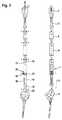
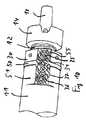
図1は、膝の一部及び遠位大腿骨の一部を交換するための関節プロステーシスとして意図される本発明に従ったプロステーシスのある例示的な実施態様を示している。プロステーシスは、シャフト1、関節機構2、及び、長さ調節機構3のような、構成部品を含む。シャフト1は、外側ロッド11と、その中心軸10にそって入れ子式に移動可能である外側ロッド11の内側を案内される内側ロッド12とを含む。外側ロッド11は、その第一端部に、雌コーンコネクタ19を有し、雌コーンコネクタ19は、必要に応じて更なるロッドセグメント(図1には示されていない)を結合するためにある。雌コーンコネクタ19を盲栓によって封止し得るし、或いは、全く省略し得る。外側ロッド11は、その第二端部に、径方向に向けられた前面を備える前方フランジ13を有する。内側ロッド12は、その第一端部に、適合する関節機構2の雌コーンコネクタ29と係合するよう構成された相補的な雄コーンコネクタ18を有する。雄コーンコネクタ18への移行部に、内側ロッド11は、鍔14を有し、固定端部に面する鍔14の一方の端面は、雄コーンコネクタ18のための停止部(ストップ)として働き、内側ロッド12のシャフトに面する鍔14の他方の端面は、調節ナット30のための停止部(ストップ)として働く。 FIG. 1 shows an exemplary embodiment of a prosthesis according to the invention intended as a joint prosthesis for exchanging part of the knee and part of the distal femur. The prosthesis includes components such as the
作動機構3は、内部一条ネジ山(single-start internal thread)を有する調節ナット30を含み、内部一条ネジ山は、内側ロッド12の上に配置される調節一条ネジ山(single-start adjustment thread)32と噛合する。調節ナット30は、その横面に、径方向ボアとして構成される複数の係合孔31を有する。複数の係合孔31は、作動部材としてのピン9(図5cを参照)を受け入れるよう構成される。ピン9は、調節ナット30を、噛合ネジ山32を有する内側ロッド12に対して回転させるために使用され、調節ナット30は、噛合ネジ山32を用いて、中心軸10に沿って移動する。その初期位置において、調節ナット30は、外側ロッド11の前方フランジ13と直接的に接触し、調節ナット30が移動するときに、外側ロッド11の前方フランジ13を調節ナット30と共に移動させる。これは外側ロッド11を内側ロッド12に対して長手軸10に沿って移動させるので、調節ナット30と鍔14との間の距離が増大し、よって、シャフト1の全長が増大する。調節ナット30が反対方向に回転されるとき、プロセスは反対方向に行われ、全長はより短くなる。 The
設定長さを固定するために、固定機構が設けられる。固定機構は、調節ロック35と、回転防止手段37とを含む。調節ロック35は、締付けネジを含み、締付けネジは、調節ナット30の径方向ボア31のうちの1つの径方向ボア内に挿入され、その先端を用いて、外側ロッド11の平坦部分15の上に作用する。結果的に、調節ナット30は、確動適合式(positive fit manner)に係止される。よって、重く且つ頻繁に変化する荷重の下でさえ、対応する長さ変化を伴う調節ナット30の有害な回転があり得ないことが確実に保証される。回転防止手段37は構造的に類似し、外側ロッド11の前方フランジ13の領域において径方向ボア内に配置される固定ネジを有する。この固定ネジは、その先端を用いて、噛合ネジ山32の領域において作用し、よって、外側ロッド11を内側ロッド12に対する回転から保護する。ひいては、それ自体既知の円錐ロック27の2つの対角的に対向する固定ネジを用いて、関節機構2に対する内側ロッド12の偶発的な回転が防止される。結果的に、関節機構2から長さ調節機構3及びシャフト1に連続的に、回転が防止される。 A fixing mechanism is provided to fix the set length. The fixing mechanism includes an
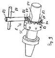
患者の成長に順応するようより大きな長さまで調節されるべき移植プロステーシスの実施例に基づき、図5に長さ調節プロセスを例示する。第一に、これはプロステーシスが最小非侵襲手術によってアクセスされること要求する。このためにはスタブ切開で十分であるのが普通である。第一ステップ(図5a)において、ネジ回し8が切開を通じて滑動され、回転防止手段37のための固定ネジと係合される。回転防止ロックはネジを緩めることによって解放される。第二ステップ(図5b)において、調節ロック35は全く同様の方法において解放される。よって、長さ調節機構3は切断されるようになり、長さ調節機構3を作動し得る。ネジ回し8は取り外され、調節ピン9が切開を通じて挿入され、調節ナット30の径方向ボア31のうちの1つと係合される。ピン9を揺動することによって、調節ナット30はある程度まで回転され、次に、ピン9は隣接する径方向ボア内に再挿入され、調節ナット30は幾分更に回転される。図示する例示的な実施態様において、ネジ山進み(thread lead)は、調節ナット30の回転毎に2mmの長さ変化が生じるように選択される。所望の長さが設定されるや否や、ピン9は引き抜かれ、ネジ回し8が再度導入され、調節ロック35(図5d)及び回転防止手段(図5e)を連続的に再装填し、よって、再活性化する。 Based on an example of a transplant prosthesis to be adjusted to a larger length to accommodate patient growth, FIG. 5 illustrates the length adjustment process. First, this requires that the prosthesis be accessed by minimal non-invasive surgery. A stub incision is usually sufficient for this purpose. In the first step (FIG. 5 a), the
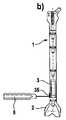
図1に例示する実施態様は、基本的なプロステーシスを示している。基本プロステーシスを図2及び3に描写するような追加的な素子で補足し得る。そこでは、追加的なシャフトセグメント5,6が設けられ、それらは、長いシャフト(図3の展開図を参照)を形成するよう、関節機構2のシャフト1及び29のコーンコネクタ18,19と適合するコーンコネクタを介して接合される。その上方端部に、大腿骨頸部プロステーシス7が配置される。よって、従来技術におけるとは異なり、漸進的な長さを有するよう設計し得るのみならず、モジュール式の長さ調節機構3の故に、むしろ無段階にさえ調節可能である、完全な大腿骨プロステーシスが形成される。これは微調整を可能にする。(図1に示すような)初期位置にある調節機構3を用いるならば、シャフト1は、シャフトセグメントのうちの1つ、例えば、シャフトセグメント5と同じ長さであるのが好ましい。結果的に、単に素子1,5を交換することによって、必要に応じて、調節可能な長さ又は固定的な長さのシャフトを形成し得る、プロステーシスシステムが提供される。 The embodiment illustrated in FIG. 1 illustrates a basic prosthesis. The basic prosthesis may be supplemented with additional elements as depicted in FIGS. There,
代替的な実施態様が図4に例示されており、そこでは、同一の素子は、同じ参照番号によって特定されている。第一の例示的な実施態様との本質的な相違は、外側ロッド11’及び内側ロッド12’が反転して配置されていること、即ち、外側ロッド11’が関節機構2の上に配置され、内側ロッド12’がコーンコネクタ19を備える第一端部を形成することに存する。そのように反転して設計される長さ調節機構3’を、図3に示すような幾つかのシャフトセグメント5,6を有する長いシャフトの第一端部にも設け得る。 An alternative embodiment is illustrated in FIG. 4, where identical elements are identified by the same reference numerals. The essential difference from the first exemplary embodiment is that the
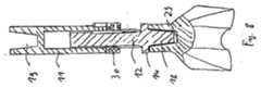
図6乃至10に示すような第二の例示的な実施態様を今や参照する。これは長さ調節機構のための特別な作動機構を含む。同じ種類の素子は、同じ参照番号によって特定されている。挿入領域43が、鍔14からシャフト12の他の自由端部まで延在している。この挿入領域43は、外部ネジ山32を含む。これは一条ネジ山であり、個々のネジ山の断面形状は、実質的に三角形であり、平坦化された山頂を備える。更に、内側ロッドは、ロッド直径の1.5倍にほぼ相当する短い案内部分45を除き、長手軸と平行に向けられた線内に多数の盲穴(bore)47がその底部に構成された長手溝46を含む。 Reference is now made to a second exemplary embodiment as shown in FIGS. This includes a special actuation mechanism for the length adjustment mechanism. Elements of the same type are identified by the same reference numbers. An
隆起として構成された触覚標識(tactile marking)55が、調節ナット30の実質的に滑らかな外側表面の上に配置されている(図7a)。8個の皿穴(counterbore)57も、均一な径方向平面内に規則的な角距離で外側表面の上に配置され、それらの1つは、触覚標識55内に配置されている。内側ロッド12に面するその下方縁部で、調節ナット30は、鍔14と相補的であるよう設計され、平面的な外側接触表面52を含む。内側ネジ山39がコバルトクロム(CoCr)で作製される調節ナット30の部分の内部に配置される。調節ナット30が全体的にコバルトクロムで構成されるのが好ましい。 A
調節ナット30は、その上方縁部に、作動機構8の一部である円周歯部81を有する。歯部81は、丸い山頂82と谷底83とを備える波状プロファイルを有する。山頂82と谷底83とを接合する斜面84は、それらの中心部分に(上方縁部56によって定められるような径方向平面に基づく)60°の傾斜を有する険しい斜面として設計されている。谷底83は外側から内側に上昇し、その結果、直角歯車駆動装置に特に適するような、円錐状に先細る歯構造をもたらす。山頂82が突出せず、上方縁部56によって定められる平面と面一に仕上がるように、歯部81は上方縁部56の外側に沿って延在する凹部80の上に配置される(図9を参照。より大きな明瞭性のために、外側ロッドを示していない)。結果的に、ある種の二重シェル構造が上方縁部にあり、アンダーカットのない平面的な接触表面を形成する円周内側リングを内側シェルとして備え、歯部81を外側シェルとして備え、歯部81の丸い山頂82は、内側リング56’と面一であり且つ同じ高さにある。 The
外側ロッド11の前方フランジ13は、実質的に平面的であり、前方フランジ13は、特にアンダーカットを欠いている、即ち、アンダーカットはどこにもない。外側ロッド11の外側表面には、縁部に隣接して第二突起51が配置されている。それは作動機構8の調節レンチ89のための軸受座として作用する。以下により詳細に記載するように、径方向ボア38と前方フランジ13との間の距離は、調節レンチ89の寸法に適合される。 The
グラブネジ(grub
screw)37を係止器具として外側ロッド11に設け得る。グラブネジ37を軸受ボア38内に螺挿し得るのが好ましく、その先端で、ネジ込み位置において、長手溝46内に、より正確には、盲穴47のうちの1つの盲穴内に突出し、よって、内側ロッド12を望ましくない変位移動から保護する。Grub screw
screw) 37 may be provided on the
調節レンチ89は、作動チャックに関して既知であるようなベベルギアキーと同様に構成される。調節レンチ89は、その後方端部に、作動ハンドル88を含み、作動ハンドル88は、最も単純な場合には、クロスバー(横木)であり得る。その前方端部に、円錐は部86が設けられ、円錐歯部86は、調節ナット30の歯部81と噛合し得るよう設計される。円錐歯部86を歯部81と係合させるために、径方向ボア38と相補的であるよう設計される前方先端に軸受ピン87が形成され、その結果、旋回軸受が形成される。径方向ボア38から前方フランジ13までの距離は、調節ナット30が径方向ボア38内に挿入されるときに、円錐歯部86が調節ナット30の歯部81と係合されるような方法において、円錐歯部86の直径に適合され、調節ナット30は、その上方縁部で、外側ロッド11の前方フランジ13と面一に位置する。 The adjustment wrench 89 is configured in the same manner as a bevel gear key as is known for actuation chucks. The adjustment wrench 89 includes an
作動機構8は、以下のように作動される。その初期状態において、調節ナット30は、内側ロッド12の外部ネジ山32の上に螺合される。内側ロッド12の外部ネジ山32は、調節ナット30の上方縁部が外側ロッド11の前方フランジ13と面一に位置するまで、外側ロッド11内に押し込まれる。軸受ボア31内に挿入される調節レンチ89を回転することによって、その円錐歯部86は、調節ナット30の歯部81と噛合し、それによって、調節ナット30の歯部81は回転され、内側ロッド12が外側ロッド11の外に押される。ここで、押し距離は、調節ナット30と協働する外部ネジ山32の進みによって並びに円錐歯部86と歯部81との間のギア比によって決定される。調節中、調節ナット30は、外側ロッド11と接触状態(近接状態)に維持される。 The
患者の成長(又は支持靱帯における伸張)が大腿骨伸張を引き起こすならば、本発明に従った内部プロステーシスをそこに適合し得る。これは調節ナット30を調節することによって行われる。このためには、小さな、よって、患者に優しい介入を用いて、駆動工具89を軸受ボア38内に挿入するだけで十分であり、調節ナット30は、回転によって再調節される。再調節の量は、調節レンチ89の回転の数によって明白に決定される。回転の数を容易に制御し得るよう、調節ナット30に触覚標識55が設けられる。その初期位置において、それは外側ロッド11の上の同じ種類の突起51と面一であり、調節ナット30が1回の完全な回転を行う度に、それは常に面一位置に戻る。これは接触によって外側から正しい位置を容易に検証することも可能にする。 If patient growth (or stretching in the supporting ligament) causes femoral stretching, an internal prosthesis according to the present invention can be adapted thereto. This is done by adjusting the
長期移植の後でさえも作動機構8が正しく機能することを保証するために、歯部保護リング50が設けられ、歯部保護リング50は、調節レンチ89の円錐歯部86のための型付け区画(mould-on section)52と、幾つかの(即ち、図示の例示的な実施態様では3つの)ピンスタブ54を含むマルチカバー53とを有する(図7b及び7cを参照)。歯部保護リング50は、調節ナット30と外側ロッド11の前方フランジ13との間に配置され、外側で歯部81を覆う。これは組織が成長して歯部内に入るのを防止し、且つ、関連する閉塞の危険性を防止する。組織が成長して径方向ボア31,38内に進入を更に防止するために、マルチカバー53が設けられる。マルチカバー53は、実質的に立方形のブロックであり、そのピンスタブ34が径方向ボア31,38内に挿入され、且つ、それらの間に締め付けられる。マルチカバー53は、図10に斜線で示される領域を覆い、よって、組織の望ましくない成長を確実に防止する。長さ調節のためには、ネジ35,37並びに歯部81への非制限的なアクセスを許容するよう、マルチカバー53を取り外す必要があるだけである。 To ensure that the
調節レンチ89の軸受ピン87を受け入れるために、図10に示す変形には、(図1乃至8に示すような組み合わせ設計の代わりに)回転からの保護をもたらすようネジ37を受け入れるボアと異なる別個のボアが設けられる。 In order to receive the bearing pin 87 of the adjusting wrench 89, the variant shown in FIG. 10 is different from the bore receiving the
長期移植の後でさえも作動機構8が正しく機能することを保証するために、歯部保護リング50が設けられ、歯部保護リング50は、調節レンチ89の円錐歯部86のための型付け区画(mould-on section)52と、幾つかの(即ち、図示の例示的な実施態様では3つの)ピンスタブ54を含むマルチカバー53とを有する(図7b及び7cを参照)。歯部保護リング50は、調節ナット30と外側ロッド11の前方フランジ13との間に配置され、外側で歯部81を覆う。これは組織が成長して歯部内に入るのを防止し、且つ、関連する閉塞の危険性を防止する。組織が成長して径方向ボア31,38内に進入を更に防止するために、マルチカバー53が設けられる。マルチカバー53は、実質的に立方形のブロックであり、そのピンスタブ54が径方向ボア31,38内に挿入され、且つ、それらの間に締め付けられる。マルチカバー53は、図10に斜線で示される領域を覆い、よって、組織の望ましくない成長を確実に防止する。長さ調節のためには、ネジ35,37並びに歯部81への非制限的なアクセスを許容するよう、マルチカバー53を取り外す必要があるだけである。
To ensure that the
Claims (21)
Translated fromJapanese第一端部と第二端部とを備える細長いシャフトと、該シャフトの前記第二端部に設けられる関節機構とを含み、
前記シャフトを入れ子式にその軸に沿って作動する長さ調節機構が設けられ、
前記シャフト及び前記関節機構は、相補的コネクタを介して結合され、
前記長さ調節機構は、モジュール式の設計であり、その近位端部及び遠位端部に、前記相補的コネクタを備え、且つ、確動適合式に作用する回転防止手段を更に備えることを特徴とする、
プロステーシス。A prosthesis for exchanging at least part of a tubular bone and an adjacent joint,
An elongated shaft comprising a first end and a second end; and a joint mechanism provided at the second end of the shaft;
A length adjustment mechanism is provided that operates the shaft in a nested manner along its axis,
The shaft and the articulation mechanism are coupled via complementary connectors;
The length adjusting mechanism has a modular design, and includes the complementary connector at the proximal end and the distal end, and further includes anti-rotation means acting positively and adaptively. Features
Prosthesis.
ことを特徴とする、請求項1乃至6のうちのいずれか1項に記載のプロステーシス。The prosthesis according to any one of claims 1 to 6, wherein the length adjusting mechanism includes a screw driving device that is contained in an initial position.
Applications Claiming Priority (3)
| Application Number | Priority Date | Filing Date | Title |
|---|---|---|---|
| EP10006098AEP2394606A1 (en) | 2010-06-11 | 2010-06-11 | Prosthetic for partial replacement of a long bone |
| EP10006098.7 | 2010-06-11 | ||
| PCT/EP2011/002875WO2011154156A1 (en) | 2010-06-11 | 2011-06-10 | Prosthesis for partial replacement of a tubular bone |
Publications (1)
| Publication Number | Publication Date |
|---|---|
| JP2013528079Atrue JP2013528079A (en) | 2013-07-08 |
Family
ID=43033053
Family Applications (1)
| Application Number | Title | Priority Date | Filing Date |
|---|---|---|---|
| JP2013513586APendingJP2013528079A (en) | 2010-06-11 | 2011-06-10 | Prosthesis for partial replacement of tubular bone |
Country Status (16)
| Country | Link |
|---|---|
| US (1) | US20130085577A1 (en) |
| EP (2) | EP2394606A1 (en) |
| JP (1) | JP2013528079A (en) |
| KR (1) | KR101493922B1 (en) |
| CN (1) | CN103002834B (en) |
| AU (1) | AU2011264072B2 (en) |
| BR (1) | BR112012031551B1 (en) |
| CA (1) | CA2802078C (en) |
| CO (1) | CO6670534A2 (en) |
| ES (1) | ES2628585T3 (en) |
| IL (1) | IL223465B (en) |
| MX (1) | MX2012014484A (en) |
| RU (1) | RU2532891C2 (en) |
| UA (1) | UA111159C2 (en) |
| WO (1) | WO2011154156A1 (en) |
| ZA (1) | ZA201209348B (en) |
Cited By (1)
| Publication number | Priority date | Publication date | Assignee | Title |
|---|---|---|---|---|
| JP2015177970A (en)* | 2014-02-27 | 2015-10-08 | 京セラメディカル株式会社 | Tibia trial for total knee replacement |
Families Citing this family (21)
| Publication number | Priority date | Publication date | Assignee | Title |
|---|---|---|---|---|
| EP2394606A1 (en)* | 2010-06-11 | 2011-12-14 | WALDEMAR LINK GmbH & Co. KG | Prosthetic for partial replacement of a long bone |
| US9532879B2 (en) | 2012-09-20 | 2017-01-03 | Depuy Ireland Unlimited Company | Femoral knee prosthesis system with augments and multiple lengths of sleeves sharing a common geometry |
| US8998996B2 (en)* | 2012-09-20 | 2015-04-07 | Depuy (Ireland) | Knee prosthesis system with standard and distal offset joint line |
| US9320603B2 (en) | 2012-09-20 | 2016-04-26 | Depuy (Ireland) | Surgical instrument system with multiple lengths of broaches sharing a common geometry |
| FR3001122B1 (en)* | 2013-01-23 | 2015-02-27 | Euros Sa | AUTOMATIC ELONGATION IMPLANT |
| CN103117018B (en)* | 2013-01-29 | 2015-12-23 | 营口巨成教学科技开发有限公司 | Simulation architecture of bone movement |
| DE102013101325B4 (en)* | 2013-02-11 | 2016-11-17 | Merete Medical Gmbh | Intermediate body for an endoprosthesis and Endoprothesenanordnung |
| CN104921796B (en)* | 2015-07-08 | 2017-06-20 | 西安交通大学 | A kind of tumorous type knee-joint prosthesis intramedullary needle |
| EP3248552A1 (en)* | 2016-05-25 | 2017-11-29 | WALDEMAR LINK GmbH & Co. KG | Tool for the production of a recess in bone tissue |
| EP3381410A1 (en)* | 2017-03-31 | 2018-10-03 | Waldemar Link GmbH & Co. KG | Connection sleeve for two anchoring shafts of two side-to-side prostheses |
| US20180353227A1 (en)* | 2017-06-07 | 2018-12-13 | Clarkson University | Adjustable length orthopedic device |
| CN108992156B (en)* | 2018-09-07 | 2024-03-15 | 北京爱康宜诚医疗器材有限公司 | Bone connector |
| CN110840632B (en)* | 2019-12-02 | 2025-08-01 | 北京爱康宜诚医疗器材有限公司 | Knee joint prosthesis |
| CN110840628B (en)* | 2019-12-02 | 2025-08-01 | 北京爱康宜诚医疗器材有限公司 | Hip joint prosthesis |
| CN111053633A (en)* | 2019-12-30 | 2020-04-24 | 北京力达康科技有限公司 | An extendable medulla needle for pediatric patient replacement surgery and method of using the same |
| CN111789702A (en)* | 2020-07-15 | 2020-10-20 | 北京力达康科技有限公司 | A child-type tumor joint prosthesis with preservation of femoral neck and knee joint surface |
| CN113101016B (en)* | 2021-05-13 | 2022-08-16 | 北京爱康宜诚医疗器材有限公司 | Prosthesis connecting element and prosthesis assembly |
| CN113367851A (en)* | 2021-05-22 | 2021-09-10 | 北京力达康科技有限公司 | Length-adjustable hip joint prosthesis |
| CN116019612B (en)* | 2023-03-30 | 2023-07-14 | 北京爱康宜诚医疗器材有限公司 | Semi-elbow joint prosthesis |
| CN117137691B (en)* | 2023-09-11 | 2024-05-03 | 南方医科大学珠江医院 | Tibia extension rod eccentric adjusting instrument |
| WO2025166409A1 (en)* | 2024-02-08 | 2025-08-14 | Signature Orthopaedics Europe Ltd | Torsion locking interface for an orthopaedic implant taper interlock |
Citations (3)
| Publication number | Priority date | Publication date | Assignee | Title |
|---|---|---|---|---|
| DE3336004A1 (en)* | 1983-10-04 | 1985-06-27 | S + G Implants GmbH, 2400 Lübeck | Endoprosthesis as a substitute for bones containing a diseased bone part which must be removed |
| EP0290767A1 (en)* | 1987-05-15 | 1988-11-17 | Howmedica GmbH | Endoprosthesis for femoral or tibial parts of joints and adjacent bone parts |
| JP2004515310A (en)* | 2000-12-15 | 2004-05-27 | スタンモア インプランツ ワールドワイド リミティッド | Module system with a wide range of applications |
Family Cites Families (13)
| Publication number | Priority date | Publication date | Assignee | Title |
|---|---|---|---|---|
| GB2094629B (en) | 1981-03-14 | 1984-08-01 | Tsnii | Artifical hip knee and femur |
| US4578081A (en)* | 1982-02-17 | 1986-03-25 | Howmedica International, Inc. | Bone prosthesis |
| US4502160A (en) | 1983-10-27 | 1985-03-05 | Dow Corning Wright | Adjustable length prosthetic joint implant |
| SU1373402A1 (en)* | 1986-06-02 | 1988-02-15 | Латвийский Научно-Исследовательский Институт Травматологии И Ортопедии | Endoprosthesis of tubular bone |
| DE3801593A1 (en) | 1988-01-21 | 1989-08-03 | Hemscheidt Maschf Hermann | GROUP CONTROL FOR HYDRAULIC SCREAM EXTENSION |
| FR2666221B1 (en)* | 1990-09-04 | 1997-11-21 | Gilles Missenard | PROSTHETIC GROWTH MODULE, EXTENSIBLE. |
| DE4039064A1 (en)* | 1990-12-07 | 1992-06-11 | Eska Medical Gmbh & Co | DEVICE FOR ADAPTING THE LENGTH OF AN ENDOPROTHESIS FOR TUBE BONES |
| US5387239A (en)* | 1993-04-19 | 1995-02-07 | Wright Medical Technology, Inc. | Adjustable length prosthetic implant |
| US6494913B1 (en)* | 1998-03-17 | 2002-12-17 | Acumed, Inc. | Shoulder prosthesis |
| DE59913637D1 (en)* | 1999-09-24 | 2006-08-10 | Link Waldemar Gmbh Co | Alloplastic replacement for a long bone |
| CN2552502Y (en)* | 2002-07-17 | 2003-05-28 | 李鼎锋 | Extension-regulating artificial joint prosthesis |
| US7435263B2 (en)* | 2003-09-30 | 2008-10-14 | Depuy Products, Inc. | Modular long bone prosthesis for partial or total bone replacement |
| EP2394606A1 (en)* | 2010-06-11 | 2011-12-14 | WALDEMAR LINK GmbH & Co. KG | Prosthetic for partial replacement of a long bone |
- 2010
- 2010-06-11EPEP10006098Apatent/EP2394606A1/ennot_activeWithdrawn
- 2011
- 2011-06-10WOPCT/EP2011/002875patent/WO2011154156A1/enactiveApplication Filing
- 2011-06-10USUS13/702,228patent/US20130085577A1/ennot_activeAbandoned
- 2011-06-10EPEP11724563.9Apatent/EP2579815B1/enactiveActive
- 2011-06-10MXMX2012014484Apatent/MX2012014484A/enactiveIP Right Grant
- 2011-06-10CNCN201180028850.7Apatent/CN103002834B/ennot_activeExpired - Fee Related
- 2011-06-10KRKR1020137000862Apatent/KR101493922B1/ennot_activeExpired - Fee Related
- 2011-06-10ESES11724563.9Tpatent/ES2628585T3/enactiveActive
- 2011-06-10JPJP2013513586Apatent/JP2013528079A/enactivePending
- 2011-06-10RURU2013100998/14Apatent/RU2532891C2/enactive
- 2011-06-10CACA2802078Apatent/CA2802078C/ennot_activeExpired - Fee Related
- 2011-06-10BRBR112012031551Apatent/BR112012031551B1/ennot_activeIP Right Cessation
- 2011-06-10AUAU2011264072Apatent/AU2011264072B2/ennot_activeCeased
- 2011-10-06UAUAA201300332Apatent/UA111159C2/enunknown
- 2012
- 2012-12-06ILIL223465Apatent/IL223465B/enactiveIP Right Grant
- 2012-12-10ZAZA2012/09348Apatent/ZA201209348B/enunknown
- 2013
- 2013-01-11COCO13004524Apatent/CO6670534A2/enactiveIP Right Grant
Patent Citations (3)
| Publication number | Priority date | Publication date | Assignee | Title |
|---|---|---|---|---|
| DE3336004A1 (en)* | 1983-10-04 | 1985-06-27 | S + G Implants GmbH, 2400 Lübeck | Endoprosthesis as a substitute for bones containing a diseased bone part which must be removed |
| EP0290767A1 (en)* | 1987-05-15 | 1988-11-17 | Howmedica GmbH | Endoprosthesis for femoral or tibial parts of joints and adjacent bone parts |
| JP2004515310A (en)* | 2000-12-15 | 2004-05-27 | スタンモア インプランツ ワールドワイド リミティッド | Module system with a wide range of applications |
Cited By (1)
| Publication number | Priority date | Publication date | Assignee | Title |
|---|---|---|---|---|
| JP2015177970A (en)* | 2014-02-27 | 2015-10-08 | 京セラメディカル株式会社 | Tibia trial for total knee replacement |
Also Published As
| Publication number | Publication date |
|---|---|
| RU2013100998A (en) | 2014-07-20 |
| MX2012014484A (en) | 2013-02-07 |
| UA111159C2 (en) | 2016-04-11 |
| AU2011264072B2 (en) | 2014-08-07 |
| EP2394606A1 (en) | 2011-12-14 |
| CA2802078C (en) | 2015-08-11 |
| EP2579815B1 (en) | 2017-04-05 |
| ES2628585T3 (en) | 2017-08-03 |
| BR112012031551A2 (en) | 2016-12-06 |
| US20130085577A1 (en) | 2013-04-04 |
| KR101493922B1 (en) | 2015-02-16 |
| IL223465B (en) | 2018-04-30 |
| CO6670534A2 (en) | 2013-05-15 |
| CN103002834B (en) | 2016-08-03 |
| KR20130028961A (en) | 2013-03-20 |
| RU2532891C2 (en) | 2014-11-10 |
| BR112012031551B1 (en) | 2020-05-19 |
| ZA201209348B (en) | 2013-08-28 |
| EP2579815A1 (en) | 2013-04-17 |
| CN103002834A (en) | 2013-03-27 |
| CA2802078A1 (en) | 2011-12-15 |
| AU2011264072A1 (en) | 2013-01-10 |
| WO2011154156A1 (en) | 2011-12-15 |
Similar Documents
| Publication | Publication Date | Title |
|---|---|---|
| JP2013528079A (en) | Prosthesis for partial replacement of tubular bone | |
| EP2948106B1 (en) | Adjustable interbody fusion device | |
| US12220324B2 (en) | Expandable vertebral prosthesis | |
| US11045327B2 (en) | Adjustable interbody fusion devices and methods of use | |
| EP2305181B1 (en) | Modular taper assembly device | |
| US8337559B2 (en) | Expandable vertebral prosthesis | |
| US10869766B2 (en) | Expandable vertebral prosthesis | |
| US20080287957A1 (en) | Insertion blade assembly and method of use | |
| EP0558203A1 (en) | Modular trial instrument with interlock mechanism | |
| EP2747712B1 (en) | Joint prosthesis | |
| CN110623776A (en) | Wrist prosthesis | |
| RU2714086C1 (en) | Prevention of vertebral implant compression | |
| US20250241767A1 (en) | Retention assemblies for intervertebral devices |
Legal Events
| Date | Code | Title | Description |
|---|---|---|---|
| A621 | Written request for application examination | Free format text:JAPANESE INTERMEDIATE CODE: A621 Effective date:20130430 | |
| A977 | Report on retrieval | Free format text:JAPANESE INTERMEDIATE CODE: A971007 Effective date:20140214 | |
| A131 | Notification of reasons for refusal | Free format text:JAPANESE INTERMEDIATE CODE: A131 Effective date:20140218 | |
| A521 | Request for written amendment filed | Free format text:JAPANESE INTERMEDIATE CODE: A523 Effective date:20140516 | |
| A02 | Decision of refusal | Free format text:JAPANESE INTERMEDIATE CODE: A02 Effective date:20140812 |