JP2013526384A - Catheter assembly comprising a receptacle containing a catheter and a wetting fluid pouch - Google Patents
Catheter assembly comprising a receptacle containing a catheter and a wetting fluid pouchDownload PDFInfo
- Publication number
- JP2013526384A JP2013526384AJP2013511640AJP2013511640AJP2013526384AJP 2013526384 AJP2013526384 AJP 2013526384AJP 2013511640 AJP2013511640 AJP 2013511640AJP 2013511640 AJP2013511640 AJP 2013511640AJP 2013526384 AJP2013526384 AJP 2013526384A
- Authority
- JP
- Japan
- Prior art keywords
- wetting fluid
- catheter
- receptacle
- fluid pouch
- catheter assembly
- Prior art date
- Legal status (The legal status is an assumption and is not a legal conclusion. Google has not performed a legal analysis and makes no representation as to the accuracy of the status listed.)
- Pending
Links
- 239000012530fluidSubstances0.000titleclaimsabstractdescription169
- 238000009736wettingMethods0.000titleclaimsabstractdescription165
- 239000000463materialSubstances0.000claimsabstractdescription47
- 230000006835compressionEffects0.000claimsabstractdescription3
- 238000007906compressionMethods0.000claimsabstractdescription3
- 230000005660hydrophilic surfaceEffects0.000claimsabstractdescription3
- 239000010410layerSubstances0.000claimsdescription39
- 238000004519manufacturing processMethods0.000claimsdescription9
- 239000002356single layerSubstances0.000claimsdescription6
- 239000000853adhesiveSubstances0.000claimsdescription5
- 230000001070adhesive effectEffects0.000claimsdescription5
- 239000002344surface layerSubstances0.000claimsdescription2
- 238000000034methodMethods0.000description7
- 238000003780insertionMethods0.000description6
- 230000037431insertionEffects0.000description6
- 239000011888foilSubstances0.000description5
- XAGFODPZIPBFFR-UHFFFAOYSA-NaluminiumChemical compound[Al]XAGFODPZIPBFFR-UHFFFAOYSA-N0.000description4
- 229910052782aluminiumInorganic materials0.000description4
- 239000005038ethylene vinyl acetateSubstances0.000description4
- 229920001200poly(ethylene-vinyl acetate)Polymers0.000description4
- 230000002485urinary effectEffects0.000description4
- 238000003466weldingMethods0.000description4
- 230000000712assemblyEffects0.000description3
- 238000000429assemblyMethods0.000description3
- 230000008901benefitEffects0.000description3
- 238000009826distributionMethods0.000description3
- -1polyethylene terephthalatePolymers0.000description3
- 229920000139polyethylene terephthalatePolymers0.000description3
- 239000005020polyethylene terephthalateSubstances0.000description3
- 230000001954sterilising effectEffects0.000description3
- 238000004659sterilization and disinfectionMethods0.000description3
- XLYOFNOQVPJJNP-UHFFFAOYSA-NwaterSubstancesOXLYOFNOQVPJJNP-UHFFFAOYSA-N0.000description3
- 239000004952PolyamideSubstances0.000description2
- FAPWRFPIFSIZLT-UHFFFAOYSA-MSodium chlorideChemical compound[Na+].[Cl-]FAPWRFPIFSIZLT-UHFFFAOYSA-M0.000description2
- 230000004308accommodationEffects0.000description2
- 230000005484gravityEffects0.000description2
- 230000036512infertilityEffects0.000description2
- TWNQGVIAIRXVLR-UHFFFAOYSA-Noxo(oxoalumanyloxy)alumaneChemical compoundO=[Al]O[Al]=OTWNQGVIAIRXVLR-UHFFFAOYSA-N0.000description2
- 229920002647polyamidePolymers0.000description2
- 229920000573polyethylenePolymers0.000description2
- 239000005033polyvinylidene chlorideSubstances0.000description2
- 239000011780sodium chlorideSubstances0.000description2
- OEPOKWHJYJXUGD-UHFFFAOYSA-N2-(3-phenylmethoxyphenyl)-1,3-thiazole-4-carbaldehydeChemical compoundO=CC1=CSC(C=2C=C(OCC=3C=CC=CC=3)C=CC=2)=N1OEPOKWHJYJXUGD-UHFFFAOYSA-N0.000description1
- 239000004698PolyethyleneSubstances0.000description1
- 239000004743PolypropyleneSubstances0.000description1
- 229920001328Polyvinylidene chloridePolymers0.000description1
- 230000004888barrier functionEffects0.000description1
- 230000005540biological transmissionEffects0.000description1
- 230000003749cleanlinessEffects0.000description1
- 239000011248coating agentSubstances0.000description1
- 238000000576coating methodMethods0.000description1
- 238000004891communicationMethods0.000description1
- 230000008878couplingEffects0.000description1
- 238000010168coupling processMethods0.000description1
- 238000005859coupling reactionMethods0.000description1
- 238000006073displacement reactionMethods0.000description1
- 230000000694effectsEffects0.000description1
- 229920002457flexible plasticPolymers0.000description1
- 238000012986modificationMethods0.000description1
- 230000004048modificationEffects0.000description1
- 229920000098polyolefinPolymers0.000description1
- 229920001155polypropylenePolymers0.000description1
- 229920001296polysiloxanePolymers0.000description1
- 238000003825pressingMethods0.000description1
- 230000008569processEffects0.000description1
- 229920005989resinPolymers0.000description1
- 239000011347resinSubstances0.000description1
- 238000000926separation methodMethods0.000description1
- 210000003708urethraAnatomy0.000description1
- 210000002700urineAnatomy0.000description1
Images


Classifications
- A—HUMAN NECESSITIES
- A61—MEDICAL OR VETERINARY SCIENCE; HYGIENE
- A61M—DEVICES FOR INTRODUCING MEDIA INTO, OR ONTO, THE BODY; DEVICES FOR TRANSDUCING BODY MEDIA OR FOR TAKING MEDIA FROM THE BODY; DEVICES FOR PRODUCING OR ENDING SLEEP OR STUPOR
- A61M25/00—Catheters; Hollow probes
- A61M25/002—Packages specially adapted therefor ; catheter kit packages
- A—HUMAN NECESSITIES
- A61—MEDICAL OR VETERINARY SCIENCE; HYGIENE
- A61M—DEVICES FOR INTRODUCING MEDIA INTO, OR ONTO, THE BODY; DEVICES FOR TRANSDUCING BODY MEDIA OR FOR TAKING MEDIA FROM THE BODY; DEVICES FOR PRODUCING OR ENDING SLEEP OR STUPOR
- A61M25/00—Catheters; Hollow probes
- A61M25/01—Introducing, guiding, advancing, emplacing or holding catheters
- A61M25/0105—Steering means as part of the catheter or advancing means; Markers for positioning
- A61M25/0111—Aseptic insertion devices
- A—HUMAN NECESSITIES
- A61—MEDICAL OR VETERINARY SCIENCE; HYGIENE
- A61M—DEVICES FOR INTRODUCING MEDIA INTO, OR ONTO, THE BODY; DEVICES FOR TRANSDUCING BODY MEDIA OR FOR TAKING MEDIA FROM THE BODY; DEVICES FOR PRODUCING OR ENDING SLEEP OR STUPOR
- A61M25/00—Catheters; Hollow probes
- A61M25/0017—Catheters; Hollow probes specially adapted for long-term hygiene care, e.g. urethral or indwelling catheters to prevent infections
Landscapes
- Health & Medical Sciences (AREA)
- Life Sciences & Earth Sciences (AREA)
- Biophysics (AREA)
- Pulmonology (AREA)
- Engineering & Computer Science (AREA)
- Anesthesiology (AREA)
- Biomedical Technology (AREA)
- Heart & Thoracic Surgery (AREA)
- Hematology (AREA)
- Animal Behavior & Ethology (AREA)
- General Health & Medical Sciences (AREA)
- Public Health (AREA)
- Veterinary Medicine (AREA)
- External Artificial Organs (AREA)
- Packages (AREA)
- Bag Frames (AREA)
- Orthopedics, Nursing, And Contraception (AREA)
Abstract
Translated fromJapaneseDescription
Translated fromJapanese本発明は、親水性カテーテル、カテーテルを湿らせるための湿潤流体(wetting fluid)を含む湿潤流体パウチ、並びにカテーテル及び湿潤流体パウチの収容用レセプタクルを含んでなるカテーテルアセンブリに関する。本発明は更にそのようなカテーテルアセンブリを製造する方法に関する。 The present invention relates to a hydrophilic catheter, a wetting fluid pouch containing a wetting fluid for wetting the catheter, and a catheter assembly comprising a receptacle for receiving the catheter and the wetting fluid pouch. The invention further relates to a method of manufacturing such a catheter assembly.
カテーテルは、膀胱ドレナージ用の尿道カテーテルなど多くの種々の医療応用においてそれらの利用法を見出している。清浄で好ましくは無菌状態にカテーテルを維持するために、カテーテルは通常製造業者によりレセプタクル中にプレパックされる。 Catheters have found their use in many different medical applications such as urinary catheters for bladder drainage. In order to keep the catheter clean and preferably sterile, the catheter is usually pre-packed in a receptacle by the manufacturer.
尿道カテーテルなどの多くのタイプのカテーテルでは、挿入を容易にするのに滑らかな外面を有することが望ましい。このために親水性尿道カテーテルは、患者の尿道へのその挿入に先立って一定期間水又は生理食塩水などの流体によって湿らせ得る親水性外面被覆を有してよい。カテーテルの使用を容易にし、そして清浄度を向上させるために、最近、破裂可能な湿潤流体パウチを含むアセンブリも開発されている。 In many types of catheters, such as urinary catheters, it is desirable to have a smooth outer surface to facilitate insertion. To this end, a hydrophilic urinary catheter may have a hydrophilic outer coating that can be wetted by a fluid such as water or saline for a period of time prior to its insertion into the patient's urethra. In order to facilitate the use of catheters and to improve cleanliness, assemblies have recently been developed that include ruptureable wet fluid pouches.
このように、今日の代表的カテーテルアセンブリは、カテーテル及び湿潤流体パウチの収容用キャビティを備えたレセプタクルを含み得る。しかしながら、湿潤流体パウチは緩んでいることから、レセプタクルがカテーテルを露出するために開けられる際に、それはレセプタクルから落ちる可能性がある。この問題を多少とも解決するために、特許文献1はレセプタクルの剥ぎ取り端部に取り付けられた湿潤流体パウチを開示している。このように、カテーテルを湿らせた後、剥ぎ取り端部は、その廃棄のために湿潤流体パウチと一緒にレセプタクルから剥ぎ取られ、そして取り除くことができる。そのような開口手順はいずれの使用者にも不便であるかもしれないが、その一方でその作業は、その四肢を動かす能力が制限された使用者など障害のある使用者にとって特に要求の厳しいものとなる。 Thus, today's typical catheter assemblies may include a receptacle with a catheter and a wetting fluid pouch receiving cavity. However, because the wetting fluid pouch is loose, it can fall out of the receptacle when the receptacle is opened to expose the catheter. In order to solve this problem to some extent, Patent Document 1 discloses a wet fluid pouch attached to a stripped end of a receptacle. Thus, after wetting the catheter, the stripped end can be stripped from the receptacle and removed with the wetting fluid pouch for disposal. Such an opening procedure may be inconvenient for any user, while the task is particularly demanding for users with disabilities, such as users with limited ability to move their limbs. It becomes.
更に便利なカテーテルアセンブリは、湿潤流体を収容するコンパートメントを含むカテーテルレセプタクルを含んでなるカテーテルアセンブリを開示する特許文献2から、公知である。コンパートメントはここではレセプタクルの一体化部材を形成するが、しかし湿潤流体コンパートメントとカテーテルを含むキャビティ間に位置する脆弱ポイントを含む分離壁によって分離される。これによって、湿潤流体は、湿潤流体コンパートメントを圧縮することによりカテーテルを含むキャビティに排出され得る。しかしながら、この解決策は上記問題を多少とも解決する一方で、一体化湿潤流体コンパートメントを備えたレセプタクルを製作する方法はむしろ複雑になる傾向がある。 A more convenient catheter assembly is known from US Pat. No. 6,057,056 which discloses a catheter assembly comprising a catheter receptacle that includes a compartment containing a wetting fluid. The compartments here form an integral part of the receptacle, but are separated by a separating wall that includes a point of weakness located between the wetting fluid compartment and the cavity containing the catheter. This allows the wetting fluid to be discharged into the cavity containing the catheter by compressing the wetting fluid compartment. However, while this solution solves some of the above problems, the method of making a receptacle with an integral wetting fluid compartment tends to be rather complicated.
このように、一般に使用し易い、一方で製造し易くそして費用効果の高いカテーテルアセンブリを提供する上で問題がある。 Thus, there are problems in providing a catheter assembly that is generally easy to use while being easy to manufacture and cost effective.
このため、上記課題を解決する代替カテーテルアセンブリの必要性がある。 Thus, there is a need for an alternative catheter assembly that solves the above problems.
従って本発明の目的は、先行技術の上記課題を克服ないしは少なくとも多少でも解決する、代替カテーテルアセンブリを提供することである。 Accordingly, it is an object of the present invention to provide an alternative catheter assembly that overcomes or at least some of the above-mentioned problems of the prior art.
本目的は補正請求の範囲に規定されるような本発明を用いて達成される。 This object is achieved using the invention as defined in the amended claims.
本発明の第1の態様によれば、
カテーテルの使用の前に湿潤流体による処理でカテーテルの低摩擦表面特性をもたらす目的の親水性表層を、その表面の少なくとも一部上に有するカテーテル;
湿潤流体を収容する密閉閉鎖(sealed closure)を形成するようにシールで接合される可撓性材料の第1及び第2の層を含んでなる湿潤流体パウチ;
カテーテル及び湿潤流体パウチの収容のためにキャビティを形成するレセプタクル、
湿潤流体パウチの圧縮によって開放可能で、それにより湿潤流体をレセプタクル中に排出することを可能にする湿潤流体パウチ:
を含んでなるカテーテルアセンブリが提供され、
ここで、湿潤流体パウチの少なくとも第1及び第2の層は、密閉閉鎖のシールを越えて伸びて密閉閉鎖の外側の取り付けエリアを形成し、湿潤流体パウチはレセプタクルの内面に取り付けられ、その取り付けはレセプタクルと取り付けエリア間だけでもたらされる。According to a first aspect of the invention,
A catheter having a desired hydrophilic surface layer on at least a portion of its surface that provides a low friction surface property of the catheter upon treatment with a wetting fluid prior to use of the catheter;
A wetting fluid pouch comprising first and second layers of flexible material joined by a seal to form a sealed closure containing the wetting fluid;
A receptacle forming a cavity for accommodation of a catheter and a wetting fluid pouch;
Wetting fluid pouch that can be opened by compression of the wetting fluid pouch, thereby allowing the wetting fluid to be discharged into the receptacle:
A catheter assembly comprising:
Here, at least the first and second layers of the wetting fluid pouch extend beyond the seal of the hermetic closure to form a mounting area outside the hermetic closure, and the wetting fluid pouch is attached to the inner surface of the receptacle and the attachment Is provided only between the receptacle and the mounting area.
湿潤流体パウチに使用される可撓性材料は、好ましくは防湿層又は低い水蒸気透過をもたらす可撓性材料である。可撓性材料は、例えば、1つ又は幾つかのアルミニウム、酸化アルミニウム、シリコーンオキシド、メタロセンポリ塩化ビニリデン(PVdC)及びポリ(エチレン−ビニルアセテート)(EVA)を含み又はそれから成り得る。例えば、可撓性材料は、塩化ビニリデン(PVdC)又はポリ(エチレン−ビニルアセテート)(EVA)などのバリア樹脂を含む、ポリアミド、ポリエチレンテレフタレート(PET)との共押し出しポリオフィンとして作ることができる。しかしながら、類似の特性を示す他の材料も実行可能である。 The flexible material used for the wetting fluid pouch is preferably a moisture proof layer or a flexible material that provides low water vapor transmission. The flexible material may comprise or consist of, for example, one or several aluminum, aluminum oxide, silicone oxide, metallocene polyvinylidene chloride (PVdC) and poly (ethylene-vinyl acetate) (EVA). For example, the flexible material can be made as co-extruded polyolefin with polyamide, polyethylene terephthalate (PET), including a barrier resin such as vinylidene chloride (PVdC) or poly (ethylene-vinyl acetate) (EVA). However, other materials that exhibit similar properties are feasible.
本発明は、湿潤流体パウチのシールの外側に位置する取り付けエリアの供給が湿潤流体パウチとレセプタクル間の堅固な取り付けを可能にするという理解に基づいている。湿潤流体パウチがレセプタクルの開口部近くに位置していたとしても、レセプタクルは開放されそしてカテーテルはレセプタクルから引き出されることから、これは湿潤流体パウチが落ちることを防ぐ。湿潤流体パウチはレセプタクルに取り付けられたままであり、そしてレセプタクルと一緒に配列され得ることから、開口手順は容易であり、その四肢を動かす能力が制限された使用者など障害のある使用者にとってもカテーテルアセンブリが実行可能となる。更に、湿潤流体パウチはレセプタクルに取り付けられたままであることから、湿潤流体パウチ中に残るいずれの湿潤流体の溢出リスクは減少する。その上、湿潤流体パウチはカテーテルの取り出しを妨害しない。 The present invention is based on the understanding that the provision of a mounting area located outside the seal of the wetting fluid pouch allows a firm attachment between the wetting fluid pouch and the receptacle. This prevents the wetting fluid pouch from falling because the receptacle is opened and the catheter is withdrawn from the receptacle, even if the wetting fluid pouch is located near the opening of the receptacle. Since the wetting fluid pouch remains attached to the receptacle and can be aligned with the receptacle, the opening procedure is easy and even for users with disabilities such as users with limited ability to move their limbs. The assembly can be executed. Further, since the wetting fluid pouch remains attached to the receptacle, the risk of overflow of any wetting fluid remaining in the wetting fluid pouch is reduced. Moreover, the wetting fluid pouch does not interfere with the removal of the catheter.
湿潤流体パウチの取り付けエリアは、医療用グレードの接着剤などの接着剤により、又は溶接によりレセプタクルの内面に取り付けられ得る。溶接は点溶接又は細長い溶接であってよい。溶接は剥離可能又は剥離不能であってよい。取り付けは単にレセプタクの内面と湿潤流体パウチの取り付けエリア間で行われるので、溶接が事実上除かれているとき、湿潤流体パウチを穿刺し又は別の方法で損傷するリスクは減少する。それはまた、カテーテルアセンブリの費用効率の高い製造を可能にする。 The attachment area of the wetting fluid pouch can be attached to the inner surface of the receptacle by an adhesive, such as a medical grade adhesive, or by welding. The welding may be spot welding or elongated welding. The weld may be peelable or non-peelable. Since the attachment is simply between the interior surface of the receptacle and the attachment area of the wetting fluid pouch, the risk of puncturing or otherwise damaging the wetting fluid pouch is reduced when the weld is effectively removed. It also allows for cost effective manufacture of the catheter assembly.
その上、湿潤流体パウチを固定位置に保つことにより、それはレセプタクルに与える影響をできるだけ小さいように位置することができる。レセプタクル中の穴は、それが使用前に検出されない場合、カテーテル使用者にとって有害となり得る製品を汚染し得ることから、このことは有利である。湿潤流体はまた、複数のカテーテルアセンブリが二次包装の内部に配置され、そして例えばe−ビームによって殺菌されるとき、最適密度が達成されるように位置し得る。e−ビームによる殺菌では、低線量を得るためそしてカテーテルアセンブリの無菌性を保証するために均一な密度分布が求められる。 Moreover, by keeping the wetting fluid pouch in a fixed position, it can be positioned so as to have as little impact on the receptacle as possible. This is advantageous because the hole in the receptacle can contaminate the product which can be harmful to the catheter user if it is not detected prior to use. The wetting fluid may also be positioned such that optimal density is achieved when multiple catheter assemblies are placed inside the secondary package and sterilized, for example, by e-beam. E-beam sterilization requires a uniform density distribution to obtain low doses and to ensure sterility of the catheter assembly.
好ましくは、湿潤流体パウチの第1及び第2の層の1つだけが、密閉閉鎖のシールを越えて伸びて、単層の取り付けエリアを形成する。一層の取り付けエリアによる利点は、材料の消耗の減少及びレセプタクルに容易に取り付けることができる、よりしなやかな接触面である。 Preferably, only one of the first and second layers of the wetting fluid pouch extends beyond the hermetic seal to form a single layer attachment area. The advantage of a single attachment area is a less supple material and a more compliant contact surface that can be easily attached to the receptacle.
実施態様によれば、湿潤流体パウチは、可撓性材料の第1及び第2の層に折り畳まれる可撓性材料の単一シートによって形成され得る。好ましくは、シートは、折り畳みの反対側に位置する可撓性材料の第1の層のエッジ、及び折り畳みの反対側に位置する可撓性材料の第2の層のエッジが互いに相対変位し(displace relative each other)得るように折り畳まれ、ここでエッジ間のエリアは取り付けエリアを形成する。これは可撓性材料のシートの中心から折り畳みを変位させることにより達成し得る。これは可撓性材料の単一層を有する取り付けエリアを備えた湿潤流体パウチを製作するのに便利な方法を提供する。 According to an embodiment, the wetting fluid pouch may be formed by a single sheet of flexible material that is folded into first and second layers of flexible material. Preferably, the sheet has a relative displacement between the edge of the first layer of flexible material located on the opposite side of the fold and the edge of the second layer of flexible material located on the opposite side of the fold ( displace relative each other), where the area between the edges forms an attachment area. This can be achieved by displacing the fold from the center of the sheet of flexible material. This provides a convenient way to make a wetting fluid pouch with a mounting area having a single layer of flexible material.
別の実施態様によれば、可撓性材料の第1及び第2の層は、密閉閉鎖を形成するようにシールによって接合される可撓性材料の2つの当初分離したシートであってよい。好ましくは、湿潤流体パウチは、可撓性材料の第1の層のエッジ及び可撓性材料の第2の層のエッジが互いに相対的に変位する、側面を有してよく、ここでエッジ間のエリアは取り付けエリアを形成する。 According to another embodiment, the first and second layers of flexible material may be two initially separated sheets of flexible material joined by a seal to form a hermetic closure. Preferably, the wetting fluid pouch may have sides where the edge of the first layer of flexible material and the edge of the second layer of flexible material are displaced relative to each other, wherein the edge between the edges This area forms a mounting area.
レセプタクルは、該レセプタクルからのカテーテルの取り出しのためにレセプタクルの開口を可能にする開口手段を備えてよい。 The receptacle may comprise opening means that allow opening of the receptacle for removal of the catheter from the receptacle.
開口手段は剥離ジョイントを含んでよい。剥離ジョイントの利点は、それがその四肢を動かす能力が制限された使用者など、障害のある使用者障害のある使用者にとっても比較的開け易いということである。しかしながら、剥離端部など他の開口手段も使用し得る。 The opening means may include a peel joint. The advantage of a peel joint is that it is relatively easy to open for users with disabilities, such as users with limited ability to move their limbs. However, other opening means such as a stripping end may be used.
湿潤流体パウチは開口手段に隣接して配置されてよい。レセプタクルが開口手順の間中同じ位置にとどまり得ることから、これは便利であり得る。例えば、レセプタクルは、開口湿潤流体パウチからカテーテルの挿入端部が位置するレセプタクルの部分まで重力によって湿潤流体が通るように保持される。レセプタクルは次いで、レセプタクルがカテーテルを取り出すのに開けられるので、その位置にとどまってよい。 The wetting fluid pouch may be located adjacent to the opening means. This can be convenient because the receptacle can remain in the same position during the opening procedure. For example, the receptacle is held such that the wetting fluid passes by gravity from the open wetting fluid pouch to the portion of the receptacle where the insertion end of the catheter is located. The receptacle can then remain in that position as the receptacle is opened to remove the catheter.
更に、湿潤流体パウチはカテーテルと開口手段間に配置され得る。この場合に湿潤流体パウチ及びカテーテルはタンデムに(互いに上に横たわる(overlie)よりもむしろ)配置されるので、湿潤流体パウチはカテーテルをレセプタクルの内面に抗して押圧することなしに圧縮され得る。これはレセプタクルへの穴又は他の損傷のリスクを低減する。更に湿潤流体パウチはカテーテルに隣接して配置されることから、e−ビームなど照射が用いられるとき、カテーテルアセンブリの殺菌に対して低線量を使用することができる。 Further, a wetting fluid pouch can be placed between the catheter and the opening means. In this case, the wetting fluid pouch and the catheter are arranged in tandem (rather than overlying each other) so that the wetting fluid pouch can be compressed without pressing the catheter against the inner surface of the receptacle. This reduces the risk of holes or other damage to the receptacle. Furthermore, since the wetting fluid pouch is positioned adjacent to the catheter, a low dose can be used for sterilization of the catheter assembly when irradiation such as e-beam is used.
別の実施態様によれば、湿潤流体パウチは、よりコンパクトなカテーテルアセンブリを実現するためにカテーテルを上に横たわらせてさせてよい。この場合に、湿潤流体パウチの取り付けエリアはカテーテルを上に横たわるように配置されることが好ましい。更に、湿潤流体を収容する密閉閉鎖はカテーテルを上に横たわらせないで、その代わりにカテーテルに対して横に配置されることが好ましい。これにまた、カテーテルアセンブリは尚更に長さ及び幅が非常にコンパクトで、そしてまた湿潤流体パウチの最も薄い部分だけがカテーテルを上に横たわるので相対的に薄くなる。 According to another embodiment, the wetting fluid pouch may cause the catheter to lie on top to achieve a more compact catheter assembly. In this case, the attachment area of the wetting fluid pouch is preferably arranged to lie over the catheter. In addition, the hermetic closure containing the wetting fluid preferably does not lie on the catheter, but instead is positioned transverse to the catheter. Again, the catheter assembly is still very compact in length and width, and is also relatively thin because only the thinnest part of the wetting fluid pouch overlies the catheter.
レセプタクルに取り付けられる取り付けエリアは、好ましくは湿潤流体パウチの片側だけに配置し得る。これは湿潤流体パウチとレセプタクル間の取り付けがヒンジ連結を形成するという効果を有する。その結果として、湿潤流体パウチはカテーテルと入れ代わるのにアタッチメント辺りを動き得るので、湿潤流体パウチはレセプタクルからのカテーテルの取り出しを妨害しない。 The attachment area attached to the receptacle may preferably be located only on one side of the wetting fluid pouch. This has the effect that the attachment between the wetting fluid pouch and the receptacle forms a hinge connection. As a result, the wetting fluid pouch does not interfere with removal of the catheter from the receptacle because the wetting fluid pouch can move around the attachment to replace the catheter.
取り付けエリアがレセプタクルに取り付けられる湿潤流体パウチの側面は、好ましくはカテーテルの軸方向に本質的に平行であってよい。これは更に、カテーテルが湿潤流体パウチのアタッチメントに沿ってスライドし得ることから、レセプタクルからのカテーテルの取り出しを容易にする。 The side of the wetting fluid pouch where the attachment area is attached to the receptacle may preferably be essentially parallel to the axial direction of the catheter. This further facilitates removal of the catheter from the receptacle as the catheter can slide along the attachment of the wetting fluid pouch.
取り付けエリアは、カテーテルの軸方向に本質的に平行な湿潤流体パウチの側面に備えられてよい。これはレセプタクルからのカテーテルの取り出しを容易にし得る。 The attachment area may be provided on the side of the wetting fluid pouch essentially parallel to the axial direction of the catheter. This can facilitate removal of the catheter from the receptacle.
更に、取り付けエリアは好ましくはレセプタクルの側端の近くに密接に取り付けられ得る。これは更にカテーテルの取り出し中の妨害を減少させる。 Furthermore, the attachment area may preferably be closely attached near the side edge of the receptacle. This further reduces interference during catheter removal.
本発明の第2の態様によれば、
レセプタクルを備える工程;
親水性カテーテルを備える工程;
カテーテルをレセプタクルのキャビティ中に配置する工程;
シールによって接合された可撓性材料の第1及び第2の層を含んでなる湿潤流体パウチを備え、湿潤流体の収容のための密閉閉鎖を形成する工程であって、ここで少なくとも1つの該第1及び第2の層は、密閉閉鎖のシールを越えて伸びて、該湿潤流体パウチを該レセプタクルに取り付けるための取り付けエリアを密閉閉鎖の外側に形成する、該工程;
レセプタクルのキャビティ中に湿潤流体を含む湿潤流体パウチを配置する;及び
上記湿潤流体パウチの取り付けエリアをレセプタクルの内面に取り付ける:
工程を含んでなる、カテーテルアセンブリを製造する方法が提供される。According to a second aspect of the invention,
Providing a receptacle;
Providing a hydrophilic catheter;
Placing the catheter in the cavity of the receptacle;
Providing a wetting fluid pouch comprising first and second layers of flexible material joined by a seal to form a hermetic closure for containment of the wetting fluid, wherein at least one said The first and second layers extend beyond the seal of the hermetic closure to form an attachment area on the outside of the hermetic closure for attaching the wetting fluid pouch to the receptacle;
Placing a wetting fluid pouch containing wetting fluid in the cavity of the receptacle; and attaching the attachment area of the wetting fluid pouch to the inner surface of the receptacle:
A method of manufacturing a catheter assembly comprising the steps is provided.
本発明の本態様は、第1の態様に関して上述と同様の利点を提供する。 This aspect of the invention provides similar advantages as described above with respect to the first aspect.
本発明のこれら及び他の態様は、以下に記載される実施態様から明らかとなりそしてそれを参照して説明されるものである。 These and other aspects of the invention will be apparent from and elucidated with reference to the embodiments described hereinafter.
目的を例示するために、本発明は、添付図面に図示されるその実施態様を参照して下記において詳細に記載されるもので、ここで: For purposes of illustration, the present invention will be described in detail below with reference to embodiments thereof illustrated in the accompanying drawings, wherein:
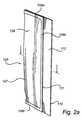
図1は、本発明の実施態様に記載のカテーテルアセンブリ100を概略的に図示する。カテーテルアセンブリ100は湿潤性レセプタクル101又はバッグを含む。レセプタクルは好ましくは可撓性プラスチック材料から成る。材料は透明であってよく、しかし不透明又は半透明材料も使用してよい。例えば、レセプタクルは、ポリエテン(polyethen)、ポリプロピレン、ポリアミド、及びPETなどの高分子材料から作ることができ、又はレセプタクルは、そのような高分子材料のラミネート及び/又はアルミニウム、酸化アルミニウム、又は配向ポリエチレン(OPP)から作ることができる。レセプタクルは前端で下方に伸びる細長いポケット102を有する。カテーテルアセンブリは更に、集尿バッグ、ドレナージチューブ等の他のデバイスに結合のためにコネクタ104を備えた、親水性尿道カテーテル103を含む。カテーテルレセプタクル101はカテーテルの収容のために適合され、そして少なくともカテーテルチューブは細長いポケット102中に収容される。好ましくは、レセプタクル101はカテーテルの全長を囲む。好ましくは、狭い前方部102及び広い後方部113を含む。狭い前方部102は、挿入端部を含むカテーテルの少なくとも一部を収容するように適合される。カテーテル全体を狭い部分102に本質的に配列することが可能である。あるいは、流出端部(しばしばコネクタ端部ともいう)を含む少なくともカテーテルの一部は、広い後方部113に伸びる。カテーテルアセンブリもまた、湿潤流体を含む湿潤流体パウチ105を含む(図示されず)。湿潤流体パウチの更なる詳細図は図2a−bに見られる。図2a−bを参照して、ここでは湿潤流体パウチは、アルミニウムラミネートなどの可撓性材料の長方形シートによって形成され、このシートは折り畳み107に沿って可撓性材料の第1の層106a及び第2の層106bに折り畳まれる。可撓性材料の第1及び第2の層は、第1の層106a及び第2の層106bが湿潤流体の収容のために密閉閉鎖114を形成するようにシールで接合される。シールはここでは3つの溶接108a−cを含む。本実施態様では、折り畳み107は、折り畳み107の反対側に位置する可撓性材料の第1の層106aのエッジ110及び折り畳み107の反対側に位置する可撓性材料の第2の層106bのエッジ111が、平行でしかし互いに相対変位しているように、長方形シートの中心線に平行であるが、それから変位しており、ここで材料の第2の層106bのエッジ111を越えて伸びる可撓性材料の第1の層106aの部分は単層の取り付けエリア112を形成し、又は別の表現では、2つのエッジ110,111間のエリアは取り付けエリア112を形成する。単層の取り付けエリアのいずれかの側面は、湿潤流体パウチをレセプタクルに取り付けるのに使用し得ることが認められる。 FIG. 1 schematically illustrates a
図1を参照して、湿潤流体パウチ105は、ここでは、カテーテル103から後方に、即ちカテーテルのコネクタ104の後ろに伸びるレセプタクルの一部113に配置される。当業者には当然のことながら、レセプタクルの後方部113はカテーテル103をハウジングする前方部102と流体連通する。 Referring to FIG. 1, a wetting
更に、湿潤流体パウチ105は、湿潤流体パウチの取り付けエリア112とレセプタクルの内面間に備えられる少なくとも1つの溶接部120によってレセプタクルに取り付けられる。溶接部120は図1に図示されるように、延長エリアを越えて伸びてよく、又は点溶接であってよい。また取り付けエリアを1つ以上の溶接によりレセプタクルに取り付けることも可能である。パウチの取り付けエリア112をレセプタクルの内面に取り付ける代替法も利用可能であり、例えば、医療グレードの接着剤などの接着剤が使用可能である。本実施態様では、取り付けエリア112が配置される湿潤流体パウチの側面は、カテーテル103の伸長に本質的に平行である。湿潤流体パウチのこの側面はここではまたパウチの長い側面である。しかしながら、当業者には当然のことながら、湿潤流体パウチのレセプタクルへの取り付けは、好ましくは取り付けエリアとレセプタクル間だけでもたらされる。 Further, the wetting
湿潤流体パウチ105は好ましくは、湿潤流体パウチにかけられる適度の外部圧が密閉閉鎖を破裂し得るように適合される。湿潤流体パウチが圧縮されるとき、誘導される内部圧の結果として、これは溶接部の分離を可能にすることによって達成することができる。例えば、3つの溶接部108−c(又はその部分)の1つは他の溶接部よりも薄く作られ、又は脆弱点を有することができる。好ましくは、レセプタクルの後端に最も近くに配置されようとしている湿潤流体パウチの側面の溶接は、カテーテルの挿入端部から最も遠くなる側面は、反対側の溶接部よりも弱く作られる。このことは、解除されたときに、湿潤流体が本質的に全レセプタクルに沿って流れ得ることを確実にし得る。 Wetting
レセプタクルを開けるための開口手段118は、ここではカテーテル103から後方に、即ちカテーテルのコネクタ104の後ろに、しかし湿潤流体パウチ105の反対側に配置される。開口手段は、例えばタブ(tabs)119a−bをバラバラに剥離し、それによりレセプタクルのフォイル壁を分離することによって、レセプタクルの開口を可能にするためにエッジから伸びるタブ119a−bに結合した剥離可能ジョイント118を含む。 The opening means 118 for opening the receptacle is here arranged behind the
カテーテル法のためのカテーテルを作製するために、密閉閉鎖114が破裂しそして湿潤流体がレセプタクル中に排出されるように、圧縮力が湿潤流体パウチ105にかけられる。これはレセプタクルを開けることなしに達成し得て、それによりレセプタクルの無菌環境は尚工程中維持される。レセプタクルは、湿潤流体がカテーテル103を収容する細長いポケット102に重力によって移行するように、カテーテルの上方へ湿潤流体パウチによって垂直に保持され得る。好ましくは、湿潤流体パウチは、十分に湿らせようとするカテーテルの挿入可能な長さに対して十分量の湿潤流体を含む。細長いポケット102への湿潤流体の放出後、レセプタクルは、レセプタクルの端部でフォイル壁を分離するために、タブ119a−bを掴み、そして剥離することにより開けることができる。レセプタクルは好ましくは、カテーテル103が、コネクタ104で容易に掴まれそしてレセプタクルから引き出されることができるように、フォイル壁の十分な程度の分離を可能にするように配置される。 To create a catheter for catheterization, a compressive force is applied to the wetting
このように、湿潤流体パウチが配置されるレセプタクルの部分は、カテーテルのコネクタまでずっと下がってフォイル壁を分離することにより折り畳んでしまうことができる。当業者には当然のことながら、レセプタクルのこの部分は多かれ少なかれ裏返しにされるが、湿潤流体パウチは取り付け溶接部120によってレセプタクルに貼り付けられたままであり得る。このように、カテーテルは取り外されていることから、レセプタクル101は湿潤流体パウチ105と一緒に配列し得る。 In this way, the portion of the receptacle in which the wetting fluid pouch is placed can be folded down down to the catheter connector and separating the foil wall. As will be appreciated by those skilled in the art, this portion of the receptacle is more or less turned over, but the wetting fluid pouch can remain attached to the receptacle by the
図3はカテーテルアセンブリの別に実施態様を図示する。この実施態様は図1及び図2を参照して論じられる実施態様に類似しているが、しかしカテーテル103及び湿潤流体パウチ105をタンデム配置する代わりに、湿潤流体パウチはカテーテル上に横たわり、よりコンパクトなカテーテルアセンブリを可能にする。この実施態様では、カテーテル103をコネクタ104で掴むことを可能にする開口部を提供するように、レセプタクルの最後の端部でフォイル壁を分離することは十分になし得る。カテーテルは次いで湿潤流体パウチに隣接して引き出され得る。湿潤流体パウチは片側だけに沿って取り付けられることから、そしてパウチの取り付け側面はカテーテルの軸方向に平行であることから、パウチはそれがカテーテルから引き出されると、カテーテルと入れ代わるのにアタッチメント辺りを動き得る。湿潤流体パウチは開口手順の間中レセプタクルの内部に残るので、湿潤流体パウチ内部に残るいずれの湿潤流体の溢出リスクも低減する。 FIG. 3 illustrates another embodiment of the catheter assembly. This embodiment is similar to the embodiment discussed with reference to FIGS. 1 and 2, but instead of placing the
湿潤流体パウチの製造方法はこれで図2を参照して記載され得る。湿潤流体パウチ105の製造方法において、パウチは、アルミニウムラミネートなどの可撓性材料の長方形シートを提供すること;可撓性材料の第1の層106a及び第2の層106bのシートの中心線に対して平行であるが、それから変位した折り畳み107に沿ってシートを折り畳むこと;そして2つの層を接合するように縦溶接部180bを提供することによって形成され得て、ここで溶接部はあまり広くない層106bのエッジ111に沿って配置される。これは可撓性材料のチューブをもたらす。チューブは湿潤流体(例えば水又は生理食塩水)で充填され、そして湿潤流体を含む密閉閉鎖114を形成するように横に溶接される。各密閉閉鎖が湿潤流体パウチを形成するために他から分離されるように、横溶接エリアでカットが行われる。縦溶接部108bの外側に残る材料の単一層は、湿潤流体パウチをレセプタクルに取り付けるために取り付けエリアを形成する。 A method of making a wetting fluid pouch can now be described with reference to FIG. In the method of manufacturing the wetting
カテーテルアセンブリ100の製造方法において、レセプタクル101が製作され、そしてカテーテル103及び湿潤流体パウチ105はレセプタクル101の内側に配置される。湿潤流体パウチの取り付けエリア112はレセプタクルの内面に取り付けられる。次いで、組立体100が殺菌される。カテーテルの殺菌は、e−ビームによる照射によって達成し得て、その場合に湿潤流体パウチ中の流体は組立体の部材の残りと同時に組み立てられるときに殺菌することができる。湿潤流体パウチは固定位置に保持されることから、それは好ましくは最適密度分布で位置することである。e−ビームで殺菌するとき、低線量を得るためそしてカテーテルアセンブリの無菌性を保証するために均一な密度分布が求められる。 In the method of manufacturing the
更に、湿潤流体パウチは好ましくは、それがレセプタクルに対して極力少ない影響を有するように位置し得る。例えば、湿潤流体パウチの外側はレセプタクルの内側と直接接触しないで、該内側から一定間隔で配置されるように、湿潤流体パウチを配置することが好ましい。レセプタクル中の穴は、それが使用前に検出されない場合に、カテーテル使用者にとって有害であり得る製品を汚染し得ることから、これは有利である。同じ趣旨で、湿潤流体パウチは鋭い角がなく作られることが好ましく、特に取り付けエリアから離れた部分では例えば丸い角の備えが好ましい。 Further, the wetting fluid pouch can preferably be positioned so that it has as little impact on the receptacle as possible. For example, it is preferable to arrange the wetting fluid pouch so that the outside of the wetting fluid pouch is not in direct contact with the inside of the receptacle and is spaced from the inside. This is advantageous because the holes in the receptacle can contaminate the product which can be harmful to the catheter user if it is not detected prior to use. For the same purpose, the wetting fluid pouch is preferably made without sharp corners, and in particular at the part away from the mounting area, for example with round corners.
図4はカテーテルアセンブリの別の実施態様を図示する。この実施態様は図1及び2を参照して論じられる実施態様に類似しているが、レセプタクルからカテーテルを取り外すための代替的方法を提案する更なる開口手段が提供される。更なる開口手段はここでは、レセプタクルの細長いポケット102に配置される剥ぎ取り線115の形態である。剥ぎ取り線は引張タブなどの1つ又は幾つかの把持ハンドル116に連結される。 FIG. 4 illustrates another embodiment of the catheter assembly. This embodiment is similar to the embodiment discussed with reference to FIGS. 1 and 2, but further opening means are provided proposing an alternative method for removing the catheter from the receptacle. The further opening means is here in the form of a tear-
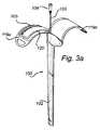
図5aは湿潤流体パウチの別の実施態様を図示する。この実施態様は図2を参照して論じられる実施態様に類似しているが、しかし湿潤流体パウチの2つの角は丸みがあり、その角は取り付けエリア112を備えた側面と反対側の湿潤流体パウチの側に位置する。これは更に、レセプタクルからのカテーテルの取り出しを容易にし得る。上述のように、丸みのある角はまたレセプタクルを損傷するリスクを低減する。尚更に、丸みのある角で得られる圧力及びストレスは鋭い角と比べて集中が少なく、それにより角での漏出のリスクを最小化する。 FIG. 5a illustrates another embodiment of a wetting fluid pouch. This embodiment is similar to the embodiment discussed with reference to FIG. 2, but the two corners of the wetting fluid pouch are rounded and the corners are opposite the wetting fluid with the mounting
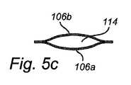
図5bは湿潤流体パウチの尚別の実施態様を図示する。ここでは可撓性材料の第1の層106a及び第2の層106bは、密閉閉鎖114を形成するように、シールによる可撓性材料ジョイントの2つの当初分離した長方形シートである。2つのシートは同じ幅を有し、しかし第1のシート106a及び第2のシート106bよりも長い。シートは、第1のシートのエッジ及び第2のシートのエッジが互いに相対変位している片側(ここでは上側)を除いて、互いにエッジ間の頂点に配置される。エッジ間のエリア112は取り付けエリアを形成する。この実施態様では、シールは小さいシートのエッジに沿って備えられた4つの溶接部108a−bを含む。同様に、第1の側面に第1の取り付けエリアを、及び第2の側面(第1の側面と反対側)に第2の取り付けエリアを備えた湿潤流体パウチは、互いに相対的に同じサイズを有する2つのシートを変位させることにより実現することができる。 FIG. 5b illustrates yet another embodiment of a wetting fluid pouch. Here, the
本発明の具体的な実施態様はこれで記載されている。しかしながら、当業者には明らかなように、幾つかの代替が可能である。例えば、記載の実施態様における湿潤流体パウチはカテーテルのコネクタの近くに配置されているが、パウチはまたカテーテルの挿入端部の近くに、又は組立体のその他の好適な位置に配置されてもよい。湿潤流体パウチの片側以上に沿った取り付けエリアを備えた湿潤流体パウチを有すること、及び湿潤流体パウチを1つ又はそれ以上のこれらの取り付けエリアを用いてレセプタクルに取り付けることもまた可能である。 Specific embodiments of the present invention are now described. However, as will be apparent to those skilled in the art, several alternatives are possible. For example, although the wetting fluid pouch in the described embodiment is disposed near the connector of the catheter, the pouch may also be disposed near the insertion end of the catheter or at any other suitable location of the assembly. . It is also possible to have a wetting fluid pouch with an attachment area along one or more sides of the wetting fluid pouch and attach the wetting fluid pouch to the receptacle using one or more of these attachment areas.
そのようなそして他の明らかな修正は、それが補正請求の範囲によって規定されるので、本発明の範囲内にあると考えられるべきである。上記の実施態様は本発明を限定するものではなくむしろ説明するものであること、そして当業者は補正請求の範囲から逸脱することなく多くの代替の実施態様を設計することが可能なことに留意する必要がある。特許請求の範囲において、括弧間に置かれるいずれの参照符号も請求の範囲を限定すると解釈されるべきではない。用語「含んでなる」は請求項中に挙げられるもの以外の要素又は工程の存在を排除するものではない。要素に先行する用語「a」又は「an」は複数のそのような要素の存在を排除するものではない。更に、単一ユニットは請求項に引用された幾つかの意味の機能を実行してよい。 Such and other obvious modifications should be considered within the scope of the present invention as it is defined by the amended claims. It is noted that the above embodiments are illustrative rather than limiting the invention, and that many alternative embodiments can be designed by those skilled in the art without departing from the amended claims. There is a need to. In the claims, any reference signs placed between parentheses shall not be construed as limiting the claim. The term “comprising” does not exclude the presence of elements or steps other than those listed in a claim. The term “a” or “an” preceding an element does not exclude the presence of a plurality of such elements. In addition, a single unit may perform several meaningful functions recited in the claims.
Claims (17)
Translated fromJapaneseカテーテルの使用の前に湿潤流体による処理でカテーテルの低摩擦表面特性をもたらす目的の親水性表層を、その表面の少なくとも一部上に有するカテーテル;
該湿潤流体を収容する密閉閉鎖を形成するようにシールで接合される可撓性材料の第1及び第2の層を含んでなる湿潤流体パウチ;
該カテーテル及び該湿潤流体パウチの収容のためにキャビティを形成するレセプタクル;
を含み、
該湿潤流体パウチは、該湿潤流体パウチの圧縮によって開口可能で、それにより湿潤流体をレセプタクル中に排出することを可能にし、
ここで、湿潤流体パウチの少なくとも上記第1及び第2の層は、密閉閉鎖のシールを越えて伸びて密閉閉鎖の外側に取り付けエリアを形成し、該湿潤流体パウチは該レセプタクルの内面に取り付けられ、該取り付けはレセプタクルと該取り付けエリア間だけで提供される、上記カテーテルアセンブリ。A catheter assembly,
A catheter having a desired hydrophilic surface layer on at least a portion of its surface that provides a low friction surface property of the catheter upon treatment with a wetting fluid prior to use of the catheter;
A wetting fluid pouch comprising first and second layers of flexible material joined by a seal to form a hermetic closure containing the wetting fluid;
A receptacle forming a cavity for receiving the catheter and the wetting fluid pouch;
Including
The wetting fluid pouch can be opened by compression of the wetting fluid pouch, thereby allowing the wetting fluid to drain into the receptacle;
Wherein at least the first and second layers of the wetting fluid pouch extend beyond the seal of the hermetic closure to form a mounting area outside the hermetic closure, the wetting fluid pouch being attached to the inner surface of the receptacle. The catheter assembly, wherein the attachment is provided only between the receptacle and the attachment area.
親水性カテーテルを備える工程;
カテーテルをレセプタクルのキャビティ中に配置する工程;
シールによって接合された可撓性材料の第1及び第2の層を含んでなる湿潤流体パウチを備え、該湿潤流体の収容のための密閉閉鎖を形成する工程であって、ここで該第1及び第2の層の少なくとも1つは、密閉閉鎖のシールを越えて伸びて、該湿潤流体パウチを上記レセプタクルに取り付けるための取り付けエリアを密閉閉鎖の外側に形成する、該工程;
レセプタクルのキャビティ中に湿潤流体を含む湿潤流体パウチを配置する工程;及び
該湿潤流体パウチの取り付けエリアをレセプタクルの内面に取り付ける工程:
を含んでなる、カテーテルアセンブリを製造する方法。Providing a receptacle;
Providing a hydrophilic catheter;
Placing the catheter in the cavity of the receptacle;
Providing a wetting fluid pouch comprising first and second layers of flexible material joined by a seal to form a hermetic closure for containment of the wetting fluid, wherein the first And at least one of the second layers extends beyond the seal of the hermetic closure to form an attachment area on the outside of the hermetic closure for attaching the wetting fluid pouch to the receptacle;
Placing a wetting fluid pouch containing a wetting fluid in a cavity of the receptacle; and attaching an attachment area of the wetting fluid pouch to the inner surface of the receptacle:
A method of manufacturing a catheter assembly, comprising:
Applications Claiming Priority (5)
| Application Number | Priority Date | Filing Date | Title |
|---|---|---|---|
| US34810410P | 2010-05-25 | 2010-05-25 | |
| EP10163767.6 | 2010-05-25 | ||
| US61/348,104 | 2010-05-25 | ||
| EP10163767.6AEP2389972B1 (en) | 2010-05-25 | 2010-05-25 | A catheter assembly comprising a receptacle accomodating a catheter and a wetting fluid pouch |
| PCT/EP2011/058414WO2011147803A1 (en) | 2010-05-25 | 2011-05-24 | A catheter assembly comprising a receptacle accommodating a catheter and a wetting fluid pouch |
Publications (1)
| Publication Number | Publication Date |
|---|---|
| JP2013526384Atrue JP2013526384A (en) | 2013-06-24 |
Family
ID=42552288
Family Applications (1)
| Application Number | Title | Priority Date | Filing Date |
|---|---|---|---|
| JP2013511640APendingJP2013526384A (en) | 2010-05-25 | 2011-05-24 | Catheter assembly comprising a receptacle containing a catheter and a wetting fluid pouch |
Country Status (9)
| Country | Link |
|---|---|
| US (1) | US8808275B2 (en) |
| EP (2) | EP2730307A1 (en) |
| JP (1) | JP2013526384A (en) |
| CN (1) | CN102892452A (en) |
| AU (1) | AU2011257329B2 (en) |
| CA (1) | CA2798187A1 (en) |
| DK (1) | DK2389972T3 (en) |
| RU (1) | RU2012155200A (en) |
| WO (1) | WO2011147803A1 (en) |
Families Citing this family (34)
| Publication number | Priority date | Publication date | Assignee | Title |
|---|---|---|---|---|
| CA141293S (en)* | 2011-01-14 | 2012-10-10 | Astra Tech Ab | Package with catheter |
| USD775522S1 (en)* | 2011-12-27 | 2017-01-03 | Dentsply Ih Ab | Catheter package |
| EP3747496A1 (en) | 2011-12-27 | 2020-12-09 | Dentsply IH AB | Catheter assembly with resealable opening |
| EP3572114A1 (en) | 2011-12-27 | 2019-11-27 | Dentsply IH AB | Temporarily foldable catheter assembly |
| GB2507474A (en)* | 2012-09-18 | 2014-05-07 | P3 Medical Ltd | Medical device with hydrophilic coating |
| SE536694C2 (en) | 2012-10-26 | 2014-05-27 | Med Tech Invest Europ Ab | Medical kit to facilitate replacement of a urinary catheter |
| CA2917047C (en) | 2013-08-30 | 2019-06-11 | Hollister Incorporated | Device for trans-anal irrigation |
| DK2845619T3 (en) | 2013-09-10 | 2019-05-06 | Ruesch Willy Gmbh | Method of manufacturing a ready-to-use catheter device and ready-to-use catheter device |
| CA3217507A1 (en) | 2014-05-30 | 2015-12-03 | Hollister Incorporated | Flip open catheter package |
| US10765796B2 (en) | 2014-07-08 | 2020-09-08 | Hollister Incorporated | Trans anal irrigation platform with bed module |
| DK3166661T3 (en) | 2014-07-08 | 2019-04-23 | Hollister Inc | Portable transanal flushing device |
| WO2016033234A1 (en) | 2014-08-26 | 2016-03-03 | C.R. Bard, Inc | Urinary catheter |
| WO2016206701A1 (en) | 2015-06-26 | 2016-12-29 | Coloplast A/S | A urinary catheter assembly |
| US11478320B2 (en)* | 2015-08-06 | 2022-10-25 | Jacobs Emerging Technologies, Llc | Medical device holder |
| RU2738996C2 (en) | 2016-04-12 | 2020-12-21 | Колопласт А/С | Catheter set with selectively removable protective case |
| US11103676B2 (en) | 2016-04-22 | 2021-08-31 | Hollister Incorporated | Medical device package with flip cap having a snap fit |
| AU2017254706B2 (en) | 2016-04-22 | 2022-04-28 | Hollister Incorporated | Medical device package with a twist cap |
| JP6821779B2 (en) | 2016-07-08 | 2021-01-27 | ホリスター・インコーポレイテッドHollister Incorporated | Transanal enema therapy device |
| US11167107B2 (en) | 2016-09-27 | 2021-11-09 | Coloplast A/S | Hydrated catheter with sleeve |
| US11497844B2 (en) | 2016-12-14 | 2022-11-15 | Hollister Incorporated | Transanal irrigation device and system |
| WO2018156589A2 (en) | 2017-02-21 | 2018-08-30 | Hollister Incorporated | Medical device package with flip cap having a snap fit |
| EP3634561B1 (en) | 2017-06-09 | 2024-02-28 | Hollister Incorporated | Packages for medical devices |
| CA3079893A1 (en) | 2017-10-25 | 2019-05-02 | Hollister Incorporated | Caps for catheter packages |
| US11666730B2 (en) | 2017-12-08 | 2023-06-06 | Hollister Incorporated | Package for medical device for ergonomic device removal |
| DK3793626T3 (en) | 2018-05-17 | 2023-03-13 | Hollister Inc | METHODS OF MANUFACTURE OF HYDROFILIC CATHETER ASSEMBLY WITH COUPLING |
| DK180417B1 (en) | 2018-07-20 | 2021-04-22 | Coloplast As | INTERMITTING URINCATHER FITTING |
| US11771584B2 (en) | 2018-12-20 | 2023-10-03 | Coloplast A/S | Urine collecting bag |
| USD971743S1 (en)* | 2019-11-11 | 2022-12-06 | Dentsply Ih Ab | Catheter package |
| CN111731681B (en)* | 2020-07-23 | 2020-11-17 | 苏州微比特自动化有限公司 | Packaging bag (WU JI KE LI) |
| US12433709B2 (en) | 2020-09-04 | 2025-10-07 | Hollister Incorporated | Medical device package with first use indicator label |
| GB202203902D0 (en)* | 2022-03-21 | 2022-05-04 | Convatec Ltd | A catheter assembly |
| WO2023180721A1 (en)* | 2022-03-21 | 2023-09-28 | Convatec Limited | A catheter assembly |
| WO2023237876A1 (en)* | 2022-06-08 | 2023-12-14 | Convatec Limited | A catheter assembly |
| EP4470592A1 (en) | 2023-06-01 | 2024-12-04 | Wellspect AB | A package for a medical device with a carrageenan barrier film |
Citations (3)
| Publication number | Priority date | Publication date | Assignee | Title |
|---|---|---|---|---|
| US3967728A (en)* | 1973-03-02 | 1976-07-06 | International Paper Company | Catheter package |
| JP2001130634A (en)* | 1999-11-10 | 2001-05-15 | Terumo Corp | Package |
| JP2009279456A (en)* | 2002-04-30 | 2009-12-03 | Astra Tech Ab | Catheter assembly |
Family Cites Families (3)
| Publication number | Priority date | Publication date | Assignee | Title |
|---|---|---|---|---|
| US3950158A (en)* | 1974-05-31 | 1976-04-13 | American Medical Products Company | Urea cold pack having an inner bag provided with a perforated seal |
| SE9904635D0 (en)* | 1999-12-17 | 1999-12-17 | Astra Ab | Catheter wetting apparatus |
| AU2000267608A1 (en)* | 2000-01-19 | 2001-07-31 | Medical Technologies Of Georgia, Inc. | Catheter package and method |
- 2010
- 2010-05-25DKDK10163767.6Tpatent/DK2389972T3/enactive
- 2010-05-25EPEP14152837.2Apatent/EP2730307A1/ennot_activeWithdrawn
- 2010-05-25EPEP10163767.6Apatent/EP2389972B1/ennot_activeNot-in-force
- 2011
- 2011-05-24CACA2798187Apatent/CA2798187A1/ennot_activeAbandoned
- 2011-05-24AUAU2011257329Apatent/AU2011257329B2/ennot_activeCeased
- 2011-05-24USUS13/114,225patent/US8808275B2/ennot_activeExpired - Fee Related
- 2011-05-24CNCN2011800242382Apatent/CN102892452A/enactivePending
- 2011-05-24WOPCT/EP2011/058414patent/WO2011147803A1/enactiveApplication Filing
- 2011-05-24JPJP2013511640Apatent/JP2013526384A/enactivePending
- 2011-05-24RURU2012155200/14Apatent/RU2012155200A/ennot_activeApplication Discontinuation
Patent Citations (3)
| Publication number | Priority date | Publication date | Assignee | Title |
|---|---|---|---|---|
| US3967728A (en)* | 1973-03-02 | 1976-07-06 | International Paper Company | Catheter package |
| JP2001130634A (en)* | 1999-11-10 | 2001-05-15 | Terumo Corp | Package |
| JP2009279456A (en)* | 2002-04-30 | 2009-12-03 | Astra Tech Ab | Catheter assembly |
Also Published As
| Publication number | Publication date |
|---|---|
| EP2730307A1 (en) | 2014-05-14 |
| WO2011147803A1 (en) | 2011-12-01 |
| EP2389972B1 (en) | 2014-01-29 |
| US20110295239A1 (en) | 2011-12-01 |
| AU2011257329B2 (en) | 2013-11-28 |
| CN102892452A (en) | 2013-01-23 |
| CA2798187A1 (en) | 2011-12-01 |
| AU2011257329A1 (en) | 2012-12-06 |
| EP2389972A1 (en) | 2011-11-30 |
| DK2389972T3 (en) | 2014-03-31 |
| US8808275B2 (en) | 2014-08-19 |
| RU2012155200A (en) | 2014-06-27 |
Similar Documents
| Publication | Publication Date | Title |
|---|---|---|
| JP2013526384A (en) | Catheter assembly comprising a receptacle containing a catheter and a wetting fluid pouch | |
| JP5385300B2 (en) | Catheter assembly having a folded urine collection bag | |
| US8740863B2 (en) | Catheter assembly | |
| AU2018279708B2 (en) | Packages for medical devices and medical device assemblies | |
| EP2609956B1 (en) | Temporarily foldable catheter assembly and associated method | |
| RU2629238C2 (en) | Catheter kit with hole made with possibility of re-sealing | |
| CN109843366B (en) | Tearable catheter assembly | |
| AU2012286141A1 (en) | Medical device assembly | |
| AU2008200776B2 (en) | Catheter assembly |
Legal Events
| Date | Code | Title | Description |
|---|---|---|---|
| A621 | Written request for application examination | Free format text:JAPANESE INTERMEDIATE CODE: A621 Effective date:20140423 | |
| A977 | Report on retrieval | Free format text:JAPANESE INTERMEDIATE CODE: A971007 Effective date:20150128 | |
| A131 | Notification of reasons for refusal | Free format text:JAPANESE INTERMEDIATE CODE: A131 Effective date:20150203 | |
| A02 | Decision of refusal | Free format text:JAPANESE INTERMEDIATE CODE: A02 Effective date:20150707 |