JP2013526338A - Introducer sheath and hemostasis valve for introducer sheath - Google Patents
Introducer sheath and hemostasis valve for introducer sheathDownload PDFInfo
- Publication number
- JP2013526338A JP2013526338AJP2013510198AJP2013510198AJP2013526338AJP 2013526338 AJP2013526338 AJP 2013526338AJP 2013510198 AJP2013510198 AJP 2013510198AJP 2013510198 AJP2013510198 AJP 2013510198AJP 2013526338 AJP2013526338 AJP 2013526338A
- Authority
- JP
- Japan
- Prior art keywords
- seal
- housing
- introducer sheath
- sheath
- opening
- Prior art date
- Legal status (The legal status is an assumption and is not a legal conclusion. Google has not performed a legal analysis and makes no representation as to the accuracy of the status listed.)
- Granted
Links
- 230000023597hemostasisEffects0.000titleclaimsabstractdescription43
- 230000002439hemostatic effectEffects0.000claimsabstractdescription30
- 210000004204blood vesselAnatomy0.000claimsabstractdescription16
- 239000008280bloodSubstances0.000claimsabstractdescription10
- 210000004369bloodAnatomy0.000claimsabstractdescription10
- 238000006073displacement reactionMethods0.000claimsabstractdescription6
- 238000011084recoveryMethods0.000claimsabstractdescription6
- 239000000463materialSubstances0.000claimsdescription13
- 229920001296polysiloxanePolymers0.000claimsdescription8
- 239000004033plasticSubstances0.000claimsdescription3
- 229920003023plasticPolymers0.000claimsdescription3
- 230000006835compressionEffects0.000claims2
- 238000007906compressionMethods0.000claims2
- -1but not limited toSubstances0.000description4
- 238000000034methodMethods0.000description4
- 238000007789sealingMethods0.000description4
- 230000036772blood pressureEffects0.000description3
- 238000001356surgical procedureMethods0.000description3
- 230000002093peripheral effectEffects0.000description2
- 229920001343polytetrafluoroethylenePolymers0.000description2
- 239000004810polytetrafluoroethyleneSubstances0.000description2
- 239000004698PolyethyleneSubstances0.000description1
- 239000004642PolyimideSubstances0.000description1
- 208000002223abdominal aortic aneurysmDiseases0.000description1
- 239000004676acrylonitrile butadiene styreneSubstances0.000description1
- 210000001367arteryAnatomy0.000description1
- 230000004323axial lengthEffects0.000description1
- 230000017531blood circulationEffects0.000description1
- 238000010586diagramMethods0.000description1
- 239000012530fluidSubstances0.000description1
- 230000003993interactionEffects0.000description1
- 230000000149penetrating effectEffects0.000description1
- 229920000573polyethylenePolymers0.000description1
- 229920001721polyimidePolymers0.000description1
- 230000007704transitionEffects0.000description1
- 230000002792vascularEffects0.000description1
- 208000019553vascular diseaseDiseases0.000description1
- 210000005166vasculatureAnatomy0.000description1
Images


Classifications
- A—HUMAN NECESSITIES
- A61—MEDICAL OR VETERINARY SCIENCE; HYGIENE
- A61M—DEVICES FOR INTRODUCING MEDIA INTO, OR ONTO, THE BODY; DEVICES FOR TRANSDUCING BODY MEDIA OR FOR TAKING MEDIA FROM THE BODY; DEVICES FOR PRODUCING OR ENDING SLEEP OR STUPOR
- A61M25/00—Catheters; Hollow probes
- A61M25/01—Introducing, guiding, advancing, emplacing or holding catheters
- A61M25/06—Body-piercing guide needles or the like
- A61M25/0662—Guide tubes
- A—HUMAN NECESSITIES
- A61—MEDICAL OR VETERINARY SCIENCE; HYGIENE
- A61M—DEVICES FOR INTRODUCING MEDIA INTO, OR ONTO, THE BODY; DEVICES FOR TRANSDUCING BODY MEDIA OR FOR TAKING MEDIA FROM THE BODY; DEVICES FOR PRODUCING OR ENDING SLEEP OR STUPOR
- A61M25/00—Catheters; Hollow probes
- A61M25/0097—Catheters; Hollow probes characterised by the hub
- A—HUMAN NECESSITIES
- A61—MEDICAL OR VETERINARY SCIENCE; HYGIENE
- A61M—DEVICES FOR INTRODUCING MEDIA INTO, OR ONTO, THE BODY; DEVICES FOR TRANSDUCING BODY MEDIA OR FOR TAKING MEDIA FROM THE BODY; DEVICES FOR PRODUCING OR ENDING SLEEP OR STUPOR
- A61M39/00—Tubes, tube connectors, tube couplings, valves, access sites or the like, specially adapted for medical use
- A61M39/02—Access sites
- A61M39/06—Haemostasis valves, i.e. gaskets sealing around a needle, catheter or the like, closing on removal thereof
- A61M39/0606—Haemostasis valves, i.e. gaskets sealing around a needle, catheter or the like, closing on removal thereof without means for adjusting the seal opening or pressure
- A—HUMAN NECESSITIES
- A61—MEDICAL OR VETERINARY SCIENCE; HYGIENE
- A61M—DEVICES FOR INTRODUCING MEDIA INTO, OR ONTO, THE BODY; DEVICES FOR TRANSDUCING BODY MEDIA OR FOR TAKING MEDIA FROM THE BODY; DEVICES FOR PRODUCING OR ENDING SLEEP OR STUPOR
- A61M39/00—Tubes, tube connectors, tube couplings, valves, access sites or the like, specially adapted for medical use
- A61M39/02—Access sites
- A61M39/06—Haemostasis valves, i.e. gaskets sealing around a needle, catheter or the like, closing on removal thereof
- A61M2039/062—Haemostasis valves, i.e. gaskets sealing around a needle, catheter or the like, closing on removal thereof used with a catheter
- A—HUMAN NECESSITIES
- A61—MEDICAL OR VETERINARY SCIENCE; HYGIENE
- A61M—DEVICES FOR INTRODUCING MEDIA INTO, OR ONTO, THE BODY; DEVICES FOR TRANSDUCING BODY MEDIA OR FOR TAKING MEDIA FROM THE BODY; DEVICES FOR PRODUCING OR ENDING SLEEP OR STUPOR
- A61M39/00—Tubes, tube connectors, tube couplings, valves, access sites or the like, specially adapted for medical use
- A61M39/02—Access sites
- A61M39/06—Haemostasis valves, i.e. gaskets sealing around a needle, catheter or the like, closing on removal thereof
- A61M2039/0626—Haemostasis valves, i.e. gaskets sealing around a needle, catheter or the like, closing on removal thereof used with other surgical instruments, e.g. endoscope, trocar
- A—HUMAN NECESSITIES
- A61—MEDICAL OR VETERINARY SCIENCE; HYGIENE
- A61M—DEVICES FOR INTRODUCING MEDIA INTO, OR ONTO, THE BODY; DEVICES FOR TRANSDUCING BODY MEDIA OR FOR TAKING MEDIA FROM THE BODY; DEVICES FOR PRODUCING OR ENDING SLEEP OR STUPOR
- A61M39/00—Tubes, tube connectors, tube couplings, valves, access sites or the like, specially adapted for medical use
- A61M39/02—Access sites
- A61M39/06—Haemostasis valves, i.e. gaskets sealing around a needle, catheter or the like, closing on removal thereof
- A61M2039/0633—Haemostasis valves, i.e. gaskets sealing around a needle, catheter or the like, closing on removal thereof the seal being a passive seal made of a resilient material with or without an opening
- A61M2039/064—Slit-valve
- A—HUMAN NECESSITIES
- A61—MEDICAL OR VETERINARY SCIENCE; HYGIENE
- A61M—DEVICES FOR INTRODUCING MEDIA INTO, OR ONTO, THE BODY; DEVICES FOR TRANSDUCING BODY MEDIA OR FOR TAKING MEDIA FROM THE BODY; DEVICES FOR PRODUCING OR ENDING SLEEP OR STUPOR
- A61M39/00—Tubes, tube connectors, tube couplings, valves, access sites or the like, specially adapted for medical use
- A61M39/02—Access sites
- A61M39/06—Haemostasis valves, i.e. gaskets sealing around a needle, catheter or the like, closing on removal thereof
- A61M2039/0633—Haemostasis valves, i.e. gaskets sealing around a needle, catheter or the like, closing on removal thereof the seal being a passive seal made of a resilient material with or without an opening
- A61M2039/0653—Perforated disc
Landscapes
- Health & Medical Sciences (AREA)
- Life Sciences & Earth Sciences (AREA)
- Heart & Thoracic Surgery (AREA)
- Animal Behavior & Ethology (AREA)
- Anesthesiology (AREA)
- Biomedical Technology (AREA)
- Hematology (AREA)
- Engineering & Computer Science (AREA)
- Pulmonology (AREA)
- General Health & Medical Sciences (AREA)
- Public Health (AREA)
- Veterinary Medicine (AREA)
- Biophysics (AREA)
- Media Introduction/Drainage Providing Device (AREA)
- Infusion, Injection, And Reservoir Apparatuses (AREA)
- Surgical Instruments (AREA)
Abstract
Translated fromJapaneseDescription
Translated fromJapanese本発明は、外科処置中に、多様な断面直径を有する外科器具および医療用デバイスの周囲の止血を維持することができる止血弁を有する導入器シースを対象とする。 The present invention is directed to an introducer sheath having a hemostatic valve capable of maintaining hemostasis around surgical instruments and medical devices having various cross-sectional diameters during a surgical procedure.
導入器シースは、多くの異なる種類の血管内処置のために、患者の血管系(典型的には、動脈)内へのガイドワイヤ、外科器具、および医療用デバイスの導入を補助する。導入器シースおよびこれに関連する拡張器は、外科器具および医療用デバイスが導入器シースを通って前進および後退できるように、皮膚および血管壁を貫通して血管内に位置決めされるように設計されている。この方法では、1回の処置に複数の外科器具および/または医療用デバイスを使用しても、皮膚および血管壁を通る導入器シースの配置は1回だけである。 Introducer sheaths assist in the introduction of guidewires, surgical instruments, and medical devices into a patient's vasculature (typically an artery) for many different types of endovascular procedures. The introducer sheath and associated dilator are designed to be positioned within the blood vessel through the skin and vessel wall so that surgical instruments and medical devices can be advanced and retracted through the introducer sheath. ing. In this way, even if multiple surgical instruments and / or medical devices are used in a single procedure, only one placement of the introducer sheath through the skin and vessel wall is required.
導入器シースは、典型的には、一般的に2つの基本的カテゴリ、すなわち受動的および能動的、に分類される弁を有している。受動的弁は、一般に、弁を通して挿入された器具または医療用デバイスによる弾性シール体の変形に依存して所望の液密シールを形成する。能動的弁は、シール体を移動させて、横断する器具または医療用デバイスと接触させる機構を有している。 Introducer sheaths typically have valves that are generally classified into two basic categories: passive and active. Passive valves generally form a desired fluid tight seal depending on deformation of the elastic seal body by an instrument or medical device inserted through the valve. The active valve has a mechanism for moving the seal body into contact with a traversing instrument or medical device.
導入器シースのための多様な受動的弁構造および能動的弁構造が提案されている。これらの構造は、様々な異なる成功度および受容度を満たしているが、それらは、一般的に、ガイドワイヤとの、かつ多様な断面直径の外科器具および医療用デバイスとの有効な止血シールを提供するシール体(受動的または能動的にかかわらず)における、共通の欠点に悩まされている。受動的弁構造は、少なくともあるサイズ、例えば、より大きいサイズの横断している器具にかなりの摩擦力を与える傾向があり、それによって、ユーザが、そのような器具を導入器シース内に挿入し、そこから後退させることが困難になる。 A variety of passive and active valve structures for introducer sheaths have been proposed. Although these structures meet a variety of different successes and acceptances, they generally provide an effective hemostatic seal with guidewires and with surgical instruments and medical devices of various cross-sectional diameters. It suffers from a common drawback in the seals it provides (whether passive or active). Passive valve structures tend to impart significant frictional forces on at least some size, eg, larger sized, transverse instruments so that a user can insert such instruments into the introducer sheath. It becomes difficult to retreat from there.
多様な導入器シースが提案されているにもかかわらず、弁のためには、依然として、単純な固定Oリングまたはグロメットが一般的に使用されている。これらの単純なシールデバイスは、外科器具の非常に狭い範囲の直径のみに対応するが、その範囲内で提供されるシールは、低い摩擦力を与える傾向がある。多くの場合、不十分なシールにより、止血を達成することができず、多くの導入器シースは、ガイドワイヤが導入器シース内に配置されるだけで漏れを起こす。 Despite various proposed introducer sheaths, simple fixed O-rings or grommets are still commonly used for valves. These simple sealing devices only accommodate a very narrow range of diameters of surgical instruments, but seals provided within that range tend to provide low frictional forces. In many cases, due to poor sealing, hemostasis cannot be achieved, and many introducer sheaths will leak if the guidewire is simply placed within the introducer sheath.
導入器シースに、さらにより厳しい要求が課される腹部大動脈瘤および他の血管疾患の治療のための、血管ステント、移植片、ステント移植片、および他の腔内補綴具の血管内配置等の血管内外科処置が開発されている。このような血管内補綴具の配置処置は、一般的に、典型的には、約11Fr〜約26Frの範囲のフレンチゲージを有する比較的大きい人工展開カテーテルの使用を伴う。 Intravascular placement of vascular stents, grafts, stent-grafts, and other endoluminal prostheses, for the treatment of abdominal aortic aneurysms and other vascular diseases where even more stringent requirements are imposed on the introducer sheath Intravascular surgical procedures have been developed. Such endovascular prosthesis placement procedures typically involve the use of relatively large prosthetic deployment catheters having a French gauge in the range of about 11 Fr to about 26 Fr.
これらの理由により、単一の導入器シースが、ガイドワイヤ、および異なる直径の器具および医療用デバイスを用いて使用し得るように、ガイドワイヤ、ならびに多様な直径を有する外科器具および医療用デバイスとの止血シールを提供することができるが、横断している器具および医療用デバイスにユーザに許容されるレベルの摩擦力を及ぼす導入器シースを提供することが望ましい。 For these reasons, guidewires and surgical instruments and medical devices having various diameters, so that a single introducer sheath can be used with guidewires and instruments and medical devices of different diameters. However, it is desirable to provide an introducer sheath that exerts a user-acceptable level of frictional force on traversing instruments and medical devices.
本発明の実施形態の態様による、血管内に挿入されるように構成される細長いシースを有する導入器シースが提供される。細長いシースは、手術器具または医療用デバイスが通過することができるように構成される中央管腔を有している。導入器シースは、シースに作動的に接続された止血弁を有している。止血弁は、細長いシースが血管内に配置されたとき、血管内の血液が導入器シースアセンブリから出ることを防止するように構成される。止血弁は、シールしてシースを支持するように構成されたハウジングと、ハウジング内に配置されハウジングによって支持される前側シールとを有している。前側シールは、円筒状側壁と、前側シール内のキャビティを構成するように側壁に対して横方向に延びるウェブとを有している。ウェブは、ガイドワイヤの一部分が止血弁を通過するとき、ガイドワイヤとの止血シールを提供するように構成される中央開口部と、開口部上の中央にある第1のスリットと、開口部の周囲に均等に離間され開口部から離れて半径方向に延びる複数の細長いリブとを有している。スリットおよび細長いリブは、外科器具または医療用デバイスが前側シールを通過することを可能にするように構成される。止血弁はまた、第1の方向に配向された第2のスリットを有する第1の中間シールも有している。第1の中間シールは、キャビティ内の前側シールによって支持される。止血弁はまた、第1の中間シールに当接して配置され、キャビティ内の前側シールによって支持される第2の中間シールも有している。第2の中間シールは、第1の方向に対して約90°である第2の方向に配向された第3のスリットを有する。第1および第2の中間シールは、ガイドワイヤの部分が止血弁を通過するとき、前側シールの開口部内のガイドワイヤを支持し、中央に合わせ、手術器具または医療用デバイスが第1および第2の中間シールを通過することを可能にし、かつガイドワイヤ、手術器具、または医療用デバイスが、止血弁内に存在しないとき、止血を形成するように構成される。止血弁はまた、第1の中間シールおよび第2の中間シールが、前側シールと後側シールとの間に位置するように、前側シールに当接して配置された後側シールも有している。後側シールは、開口部を有するウェブを有する。ウェブは、それぞれの器具およびデバイスが個々に止血弁を通過するとき、複数の異なるサイズの外科器具および医療用デバイスとの止血シールを提供するように構成される。複数の異なるサイズは、直径約3mm〜約9mmの範囲である。ハウジングは、前側シール、第1の中間シール、第2の中間シール、および後側シールを通る器具またはデバイスの移動によってもたらされるシールの変位によって誘発される歪みに対する歪み回復を提供するように構成される。 In accordance with aspects of an embodiment of the present invention, an introducer sheath is provided having an elongated sheath configured to be inserted into a blood vessel. The elongate sheath has a central lumen configured to allow a surgical instrument or medical device to pass through. The introducer sheath has a hemostasis valve operatively connected to the sheath. The hemostatic valve is configured to prevent blood within the blood vessel from exiting the introducer sheath assembly when the elongated sheath is disposed within the blood vessel. The hemostasis valve has a housing configured to seal and support the sheath, and a front seal disposed within and supported by the housing. The front seal has a cylindrical side wall and a web that extends transversely to the side wall to define a cavity in the front seal. The web includes a central opening configured to provide a hemostatic seal with the guide wire when a portion of the guide wire passes through the hemostasis valve, a first slit in the center on the opening, A plurality of elongated ribs that are equally spaced around the periphery and extend radially away from the opening. The slit and elongated rib are configured to allow a surgical instrument or medical device to pass through the front seal. The hemostasis valve also has a first intermediate seal having a second slit oriented in a first direction. The first intermediate seal is supported by the front seal in the cavity. The hemostasis valve also has a second intermediate seal that is positioned against the first intermediate seal and supported by the front seal in the cavity. The second intermediate seal has a third slit oriented in a second direction that is approximately 90 ° to the first direction. The first and second intermediate seals support and center the guidewire in the opening of the anterior seal when a portion of the guidewire passes through the hemostasis valve and the surgical instrument or medical device is the first and second And is configured to form hemostasis when no guidewire, surgical instrument, or medical device is present in the hemostasis valve. The hemostasis valve also has a rear seal disposed against the front seal such that the first intermediate seal and the second intermediate seal are located between the front seal and the rear seal. . The rear seal has a web having an opening. The web is configured to provide a hemostatic seal with a plurality of different sized surgical instruments and medical devices as each instrument and device individually passes through the hemostasis valve. The plurality of different sizes range from about 3 mm to about 9 mm in diameter. The housing is configured to provide strain recovery against strain induced by displacement of the seal caused by movement of the instrument or device through the front seal, the first intermediate seal, the second intermediate seal, and the rear seal. The
本発明の態様による、導入器シース用の止血弁が提供される。止血弁は、ハウジングと、ハウジング内に配置され、かつそれによって支持される前側シールとを有している。前側シールは、円筒状側壁と、前側シール内のキャビティを構成するように側壁に対して横方向に延びるウェブとを有している。ウェブは、ガイドワイヤの一部分が止血弁を通過するとき、ガイドワイヤとの止血シールを提供するように構成される中央開口部と、を有している。開口部上の中央にある第1のスリットと、開口部の周囲に均等に離間され、開口部から離れて半径方向に延びる複数の細長いリブとを有している。スリットおよび細長いリブは、外科器具または医療用デバイスが前側シールを通過することを可能にするように構成される。止血弁はまた、第1の方向に配向された第2のスリットを有する第1の中間シールも有している。第1の中間シールは、キャビティ内の前側シールによって支持される。止血弁はまた、第1の中間シールに当接して配置されキャビティ内の前側シールによって支持される、第2の中間シールも有している。第2の中間シールは、第1の方向に対して約90°である、第2の方向に配向された第3のスリットを有する。第1および第2の中間シールは、ガイドワイヤの部分が止血弁を通過するとき、前側シールの開口部内のガイドワイヤを支持し、中央に合わせ、手術器具または医療用デバイスが第1および第2の中間シールを通過することを可能にし、かつガイドワイヤ、手術器具、または医療用デバイスが、止血弁内に存在しないとき、止血を形成するように構成される。後側シールは、第1の中間シールおよび第2の中間シールが、前側シールと後側シールとの間に位置するように、前側シールに当接して配置される、後側シールは、開口部を有するウェブを有する。ウェブは、それぞれの器具およびデバイスが個々に止血弁を通過するとき、複数の異なるサイズの外科器具および医療用デバイスとの止血シールを提供するように構成される。複数の異なるサイズは、直径約3mm〜約9mmの範囲である。ハウジングは、前側シール、第1の中間シール、第2の中間シール、および後側シールを通る器具またはデバイスの移動によってもたらされる変位によって誘発される歪みに対する歪み回復を提供するように構成される。 In accordance with aspects of the present invention, a hemostasis valve for an introducer sheath is provided. The hemostasis valve has a housing and a front seal disposed within and supported by the housing. The front seal has a cylindrical side wall and a web that extends transversely to the side wall to define a cavity in the front seal. The web has a central opening configured to provide a hemostatic seal with the guidewire as a portion of the guidewire passes through the hemostasis valve. There is a first slit in the center of the opening, and a plurality of elongated ribs that are evenly spaced around the opening and extend radially away from the opening. The slit and elongated rib are configured to allow a surgical instrument or medical device to pass through the front seal. The hemostasis valve also has a first intermediate seal having a second slit oriented in a first direction. The first intermediate seal is supported by the front seal in the cavity. The hemostasis valve also has a second intermediate seal disposed against the first intermediate seal and supported by the front seal in the cavity. The second intermediate seal has a third slit oriented in a second direction that is approximately 90 ° to the first direction. The first and second intermediate seals support and center the guidewire in the opening of the anterior seal when a portion of the guidewire passes through the hemostasis valve and the surgical instrument or medical device is the first and second And is configured to form hemostasis when no guidewire, surgical instrument, or medical device is present in the hemostasis valve. The rear seal is disposed in contact with the front seal so that the first intermediate seal and the second intermediate seal are located between the front seal and the rear seal. Having a web with The web is configured to provide a hemostatic seal with a plurality of different sized surgical instruments and medical devices as each instrument and device individually passes through the hemostasis valve. The plurality of different sizes range from about 3 mm to about 9 mm in diameter. The housing is configured to provide strain recovery against strain induced by displacement caused by movement of the instrument or device through the front seal, the first intermediate seal, the second intermediate seal, and the rear seal.
例として、対応する参照記号が対応する部品を示す付随の概略図を参照して、今から本発明の実施形態が記載される。少なくとも1つの図面は、原寸に比例し得る。 By way of example, embodiments of the present invention will now be described with reference to the accompanying schematic diagram, in which corresponding reference symbols indicate corresponding parts. At least one drawing may be proportional to the original size.
以下の発明を実施するための形態は、単に、事実上の例示であり、本発明または本発明の適用および使用を制限することを意図しない。先述の技術分野、背景技術、発明の概要、または以下の発明を実施するための形態に提示されている、いかなる表現された、または黙示の理論に拘束されないことを意図する。 The following detailed description is merely exemplary in nature and is not intended to limit the invention or the application and uses of the invention. It is intended not to be bound by any expressed or implied theory presented in the preceding technical field, background, summary of the invention or the following detailed description.
図1および図2は、本発明の実施形態による導入器シース10を概略的に示す。図示されているように、導入器シース10は、止血弁12と、弁12の1つの端部から延びる細長いシース14とを有している。シース14は、下記にさらに説明されるように、血管等の血液が流れる身体管腔内に挿入されるように構成された略円筒状で細長い中空部材である。血管に導入される、任意の好適に寸法決定された手術器具または医療用デバイスが、導入器シース10のシース14を介して導入されるが、シース14の内側管腔16(図2を参照)は、例えば、拡張器18を受け入れるように寸法決めされ構成されている。 1 and 2 schematically illustrate an
一実施形態では、導入器シース10は、最小の直径のシースを外科処置中に使用できるように、キットの一部である異なる直径を有する複数のシース14を含んでもよい。例えば、キットの一部の1つのシースは、11〜13Frのカテーテルを扱うように構成され、別のシースは、14〜16Frのカテーテルを扱うように構成されている。 In one embodiment,
図1および図2に示されているように、シース14の一端は、弁12に作動的に接続さされている。弁12は、内側前方部分22および内側前方部分22に接続されている内側後方部分24を有する外側ハウジング20と、外側ハウジング20の内側前方部分22に作動的に接続された内側ハウジング26とを有している。弁12はまた、図2に示されているように、内側ハウジング26およびシース14を受け入れ、支持するように構成された外側ハウジング20の内側前方部分22に接続されたシースシール28も有している。 As shown in FIGS. 1 and 2, one end of the sheath 14 is operatively connected to the
シースシール28は、ほぼ円錐状の部分30と、ほぼ円筒状の部分32とを有している。円筒状部分32は、ハウジング20の内側前方部分22のリップすなわち内側フランジ36を受け入れるように構成される、外面上の溝34を有し、それによって、円筒状部分32が、外側ハウジング20に固着されたまま、外側ハウジング20内に延びることを可能にする。シースシール28の円錐状部分30は、血液がシースシール28とシース14との間を流れることができないように、シース14をシールして受け入れるように構成された内側管腔38を有する。一実施形態では、内側管腔38は、締り嵌合が達成されるように、シース14の外径より小さい直径を有する。異なるサイズのシースを有するキットの一部として、キットは、シールがすべてのシース14に提供されるように、それぞれ、シース14の1つをシールして受け入れるように構成された内側管腔38を有する異なるシースシール28も含んでもよい。 The
シースシール28はまた、内側管腔38から延び、内側ハウジング26の円錐状部分42、および内側ハウジング26の円筒状部分44の少なくとも一部分を受け入れるように構成されたキャビティ40も有している。図2に示されているように、内側ハウジング26は、略中空であり、弁12およびシース14内に挿入される拡張器18、または他の好適に寸法決定された手術器具もしくは医療用デバイスを支持するように構成される円錐状部分42の頂点に開口部46を有する。フランジ50は、開口部46に対向する内側ハウジング26の端部に配置されている。フランジ50が、図2に示されているように、外側ハウジング20が内側ハウジング26を支持するように、外側ハウジング20の内面に係合するように構成される。 The
内側ハウジング26は、さらに、環状突出部27を有し、この環状突出部27は、シースシール28の内側表面内の環状凹部29に受け入れられるように構成された鉤状の断面形状を有し、環状凹部は、内側ハウジング26の環状突出部27を受け入れこれを係止すような対応する形状を有している。環状突出部27と環状凹部29との間のこの係合関係は、シースシール28を、外側ハウジング20の内側前方部分22の内部に係合されたままにするのを補助し、ならびに、シース14が血管内に挿入されているとき、シース14が外側ハウジング20内に押出されるのを防止するのを補助する。 The
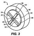
前側シール52が、外側ハウジング20の内側後方部分24によって支持され、リップすなわち内側フランジ36に対向する外側ハウジング20の内側前方部分22の端部54に係合するように構成されている。前側シール52の一実施形態のさらなる詳細は、図3に示されている。図示されているように、前側シール52は、ほぼ円筒状の側壁56と、中央のほぼ円筒状の隆起部分59を形成するように側壁56に対して横方向に延びるウェブ58とを有している。ウェブ58は、中央開口部60と、開口部60の中央に置かれこれを通過するスリット62と、隆起部分59の外縁65から中央開口部60に向かって延びる任意に複数のリブ64とを有している。中央開口部60は、ガイドワイヤが通過するとき、ガイドワイヤとの止血シールを形成するように構成されるが、ガイドワイヤを支持するようには構成されてはいない。スリット62は、図面に示されているカテーテルまたは拡張器18等の外科器具または医療用デバイス等のデバイスが、公称抵抗値で、前側シール52を通過することを可能にするように構成されている。任意の複数のリブ64は、デバイスが弁12から取り外されたとき、スリット62を閉口するのを補助するように構成されている慣性構造を提供するように構成されている4つのリブ64が図3に示されているが、それより多くまたはそれより少ないリブが使用でき、他の図に示されているように、前側シールのこの側面上のリブは、完全に欠如している。図示されている実施形態は、決して、制限するものであると意図しない。 A
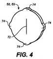
図2に示されているように、前側シール52は、2つの中間シール68、69を支持するように構成されたキャビティ66を有している。2つの中間シール68、69は、ほぼ同一のディスク状構造70を有し、その一実施形態が、図4に示されている。図示されているように、各シール68、69のディスク状構造70は、ディスク状構造70の中央を横切って延びるスリット72と、ディスク状構造70の中央から離れて半径方向に延びる複数の円周方向の突出部74とを有している。スリット72は、その閉口位置構造で弛緩されるとき、予測される範囲の正常なヒトの血圧、例えば、140/80mm−Hgで、血液に対して液密である。突出部74のそれぞれは、前側シール52のキャビティ66内の一致する凹部によって受け入れられるように構成されている。組み立て時に、中間シール68、69は、スリット72が90°離れて配向されるように、前側シール52内で配向されている。中間シール68、69は、ガイドワイヤが弁12を通過するとき、ガイドワイヤを支持し、外側ハウジング20内で、かつ前側シール52の開口部60との関係で、ガイドワイヤを中央に合わせるように構成されている。 As shown in FIG. 2, the
図2に示されているように、後側シール76はフランジ78を有し、このフランジ79は、一方の側で前側シール52に係合し、反対側で外側ハウジング20の内側後方部分24に係合し、ハウジング20の内側後方部分24がハウジングの20の内側前方部分22に連結されたとき、後側シール76が、中間シール68、69を間に配置した状態で、前側シール52とシールを形成する。フランジ78は、拡張器18等の導入器シース10内に挿入されているデバイスを受け入れるように構成された開口部80を有している。図示されているように、後側シール76は、中間シール69に対して押圧されるように構成された中央の隆起部分82を有している。隆起部分82は、フランジ78内の開口部80よりも小さい開口部84を有してもよいが、拡張器18が後側シール76を通過することを可能にするように構成されている。一実施形態では、開口部84は、スカート86が、後側シール76に対して一部の抵抗を有する拡張器18を移動させ、拡張器18との止血シールを提供することを可能にするように、より大きい直径の拡張器18が開口部を通過するとき、伸びるように構成された薄いウェブ86によって囲まれている。 As shown in FIG. 2, the
図5および図6は、本発明の実施形態による、導入器シース100を示す。図示されているように、導入器シース100は、止血弁112と、弁112の一端から延びる細長いシース114とを有している。一実施形態では、シース114は、上述のシース14と同一の設計であってもよい。図示されているように、シース114は、弁112内に配置されたシース114の一端にフランジ115を有している。血管に導入される任意の好適に寸法決定された手術器具または医療用デバイスが、導入器シース100のシース114を介して導入されるが、シース114の内部管腔116は、例えば、拡張器118を受け入れるように寸法決定され、形成されている。 5 and 6 show an
図5および図6に示されているように、シース114の一端は、弁112に作動的に接続されている。弁112は、下記により詳細に記載されるように、外側ハウジング120と、外側ハウジング120によって支持される内側ハウジング126とを有している。図示されているように、シース114のフランジ115は、内側ハウジング126の一部分と外側ハウジング120との間に配置されている。 As shown in FIGS. 5 and 6, one end of the
外側ハウジング120は、ほぼ円錐状の部分130と、ほぼ円筒状の部分132を有している。外側ハウジング120の円錐状部分130は、血液が、外側ハウジング120とシース114との間で流れることができないように、シース114をシールして受け入れるように構成される内側管腔138を有する。一実施形態では、内側管腔138は、締り嵌合が達成されるように、シース114の外径より小さい直径を有する。図1および図2に示されている弁12の実施形態と比較すると、図5および図6に示されている弁112の外側ハウジング120は、外側ハウジング20およびシースシール28の両方の機能を提供する。 The
図7および図8は、より詳細に、反対方向にひっくり返された外側ハウジング120および内側ハウジング126を示す。外側ハウジング120はまた、内側管腔138から延在し、内側ハウジング126の円錐状部分142および内側ハウジング126の円筒状部分144を受け入れるように構成されたキャビティ140を有している。内側ハウジング126は、略中空であり、弁112内およびシース114内に挿入される拡張器118または任意の好適に寸法決定された手術器具もしくは医療用デバイスを支持するように構成された円錐状部分142の一端において開口部146を有している。 7 and 8 show in more detail the
図7に示されているように、内側管腔138およびキャビティ140に加えて、外側ハウジング120は、リップまたは内側フランジ148と、キャビティ140の最大直径より小さい直径を有する内側フランジ148内の開口部149とを有している。内側フランジ148は、図5に示されているように、内側ハウジング126の端部150に当接するように構成されている。キャビティ140を構成する外側ハウジング120の内側表面122は、図5にも示されているように、内側ハウジング126の外周レッジ152に当接するように構成された内周レッジ124を有している。 As shown in FIG. 7, in addition to the
図8に示されているように、内側ハウジング126の内部表面154はまた、円筒状部分144と内側ハウジング126の円錐状部分142との間の移行部が位置する、内周レッジ156も有している。内側ハウジング126の内周レッジ156および外周レッジ152は、互いからわずかに軸方向にオフセットされている。 As shown in FIG. 8, the
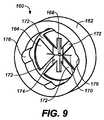
前側シール160は、図5に示されているように、内側ハウジング126内に配置され、それによって支持されている。前側シール160のさらなる詳細は、図9および図10に示されている。図示されているように、前側シール160は、ほぼ中空の円筒状側壁162と、外面166を形成するように、側壁162の環との間の隙間にわたって横方向に(スパン)延びるウェブ164とを有している。側壁162の外面は、図10に示されているように、円周レッジ163が形成されるように、階段状である。前側シール160の円周レッジ163は、図5および8に示されているように、内側ハウジングの内周レッジ156に対して当接するように構成されている。 The
ウェブ164は、中央開口部168と、開口部168の中央に置かれこれを通過するスリット170と、側壁162の内部表面から開口部168に向かって半径方向内向きに延びる複数のリブ172と、スリット170に対して約90°の角度で開口部168を横切って延びる凹部174とを有している。図9に示されているように、開口部168の近傍の各リブ172の端部は、凹部174内へリブが移行するにつれて先細にされている。中央開口部168は、ガイドワイヤがそこを通過するとき、ガイドワイヤとの止血シールを形成するように構成されているが、ガイドワイヤを支持するようには構成されない(ウェブ164上のガイドワイヤのみの重量が、止血を防止するために開口部の形状を変形することを意味する)。一実施形態では、開口部168は、約0.87mm〜約0.90mmの直径を有する。一実施形態では、開口部168は、約0.89の直径を有する。 The
スリット170は、拡張器118等のデバイスが、公称抵抗値で前側シール160を通過することができるように構成されている。凹部174および複数のリブ172は、デバイスが弁112内に挿入されたとき、スリット170が開口し、デバイスが弁12から取り外されたとき、閉口(その歪みを回復する)できるように、慣性(支持)構造を提供するように構成されている。4つのリブ172が図9に示されているが、それより多くまたはそれより少ないリブを使用してもよい。
図9に示されているように、前側シール160の側壁162の内側表面は、複数の凹部176を有している。凹部(半円筒状スロット)176は、図4に示されている中間シール68、69の突出部74を受け入れるように構成されている。図5に示されているように、中間シール68、69は、前側シール160内に配置され、それによって支持されている。図4に関して上述した同じ中間シール68、69を、図5および図6の導入器シース100の実施形態に使用してもよい。図6に示されているように、中間シール68、69は、シール68、69のスリット72が90°離れて配向されるように、互いに対して配向されている。中間シール68、69は、ガイドワイヤが弁112を通過するとき、ガイドワイヤ(または、他のデバイス)を支持し、外側ハウジング120内、かつ前側シール160内の開口部168との関係で、ガイドワイヤを中央に合わせるように構成されている。 As shown in FIG. 9, the inner surface of the
図5および図6に示されているように、弁112はまた、後側シール180を有している。後側シール180の一実施形態は、図11により詳細に示されている。図示されているように、後側シール180は、フランジ182と、フランジ182の一側面から延びる主要本体部分184とを有している(図6に示されている)。主要本体部分184よりも小さい直径および軸線方向長さを有する、より小さい本体部分186は、図11に示されているように、主要本体部分184として、フランジ182の反対側の側面から延びる。主要本体部分184は、導入器シース100内に挿入された器具またはデバイスの直径よりも大きい直径を有する、大きい開口部188(図6を参照)を有している。より小さい本体部分186は、前側シール160の開口部168よりも大きいが、主要本体部分184の大きい開口部188よりも小さい、開口部190を有している。より小さい開口部190は、止血シールが、後側シール180と拡張器118等のデバイスとの間に形成されるように、導入器シース100内に挿入されるガイドワイヤの直径よりも大きいが、導入器シース100内に挿入される器具またはデバイスの直径よりも小さい直径を有する。開口部190は、拡張器118が後側シール180を介して押圧されたとき、伸びるように構成された薄い可撓性ウェブ192に形成されている。図5に示されているように、より小さい本体部分186は、中間シール69に対して当接するように構成され、フランジ182は、内側ハウジング126内に、かつ前側シール160の一端と外側ハウジング120の内側フランジ148との間に配置されるように構成されている。圧縮力は、前側シール160および外側ハウジング120によって、フランジ182に印加され、内側ハウジング126の円錐状部分142に進入する任意の血液が、開口部149を介して外側ハウジング120を出ることができないように、後側シール180と外側ハウジング120との間のシールを作成する。側面ポート(番号付けされていない)は、吸引接続部として機能することができ、シリンジおよび針を使用する吸引機能を実施するために、シリンジの針端を使用して、ポートの端部上の薄い壁を穿孔できる。 As shown in FIGS. 5 and 6, the
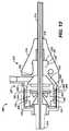
図12〜図14は、別の実施形態の導入器シース200を示す。図12に示されているように、導入器シース200は、細長いシース214と、シース214を支持する止血弁212とを有している。導入器シース200を介して血管内に導入される必要がある、任意の好適な手術器具または医療用デバイスは、拡張器218の代わりに使用できるが、導入器シース214内に挿入される拡張器218が示されている。図12〜図14に示されている導入器シース200の部品の多くの機能が、上述の導入器シース10、100の対応する部品によって提供される機能と同一であるため、一般的に、様々な部品の構造における差異のみが、本明細書において記載されている。 12-14 illustrate an alternative embodiment introducer
例えば、弁212は、内側前方部分222と、内側前方部分222に作動的に接続された内側後方部分224とを有するハウジング220を有している。内側前方部分222は、一般的に、第1の直径を有する第1の円筒状部分226と、第1の直径を超える第2の直径を有する第2の円筒状部分228と、第1の円筒状部分226および第2の円筒状部分228を接続する円錐状部分230とを有している。第1の円筒状部分226は、シースシール236の環状凹部234によって受け入れられるように構成された先細のフランジ232を一端に有する。 For example, the
シースシール236は、対応する係合表面を有する、環状凹部234およびフランジ232を介して、ハウジング220の内側前方部分222に作動的に接続されるように構成されている。シースシール236は、血液が、シースシール236の内側から、シースシール236とシース214との間のシース214の外側まで通過することができないように、シース214とのシールを作成する方法で、シース214を受け入れるように構成された中央管腔238を有している。 The
ハウジングの第2の円筒状部分228は、図12に示されているように、前側シール240、第1の中間シール242、第2の中間シール244、および後側シール246の少なくとも一部分を受け入れるように構成されている。前側シール240は、図3により詳細に示されている前側シール52、または図9および10により詳細に示されている前側シール160と同一、またはほぼ同一の設計を有してもよい。前側シール240の円筒状側壁248は、ハウジングの第2の円筒状部分228の内部環状レッジ252に対して当接するように構成された環状レッジ250を有している。前側シール240の外径、およびハウジング220の内側前方部分222の第2の円筒状部分228の内径は、ハウジング220の内側前方部分222の内の前側シール240の公称嵌合またはわずかな締り嵌合が存在するように、ほぼ同一であることが望ましい。 The second
第1の中間シール242および第2の中間シール244は、上述しかつ図4に示されているシール68、69とほぼ同一の設計を有してもよい。例えば、第1の中間シール242は、第1の方向に延びるスリットを有し、第2の中間シール244は、中間シール242、244が、前側シール240の円筒状側壁248によって形成された内部キャビティ内に配置されるときの方向から約90°に配向される第2の方向に延びるスリットを有してもよい。図13および図14に示されているように、第1の中間シール242および第2の中間シール244はそれぞれ、円筒状側壁248の内部表面内の凹部258と連結する他に、第1および第2の中間シール242、244が、互いに連結するように、少なくとも1つの突出部254と、他のシールの突出部254を受け入れるように構成された、少なくとも1つの凹部256を有する。 The first
後側シール246は、図12に示されているように、前側シール240の(円筒状側壁248の)後端表面262に当接するように構成されたフランジ260を有している。後側シール246はまた、ウェブ192と同様である開口部(図示せず)と、図11に示されている後側シール180の開口部190とを有するウェブも有している。後側シール246の前端表面264は、第2の中間シール244に当接するように構成されている。図13および14に示されているように、ハウジング220の内側後方部分224は、シール240、242、244、246が、ハウジング220の軸線方向に圧縮された挟着関係にあるように、ハウジング220の内側後方部分224の前端表面266が、後側シール260に対して押圧するように、ハウジング220の内側前方部分222内に押圧嵌合されるように構成された保持環の形状である。 The
細長いシース14、114、214は、ポリテトラフルオロエチレン(PTFE)、ポリエチレンアクリル酸ブチル(PEBA)、ポリエチレン、およびポリイミドを有するが、それらに限定されない、任意の好適な材料から作製できる。 The
前側シール52、160、240、第1の中間シール68、242、第2の中間シール69、244、および後側シール76、180、246は、同一の材料から作製され、約35〜約55の範囲、例えば約40〜約50の範囲のショアAデュロメータ値を有するシリコーン材料である。 The front seals 52, 160, 240, the first
外側ハウジング20、内側ハウジング126、およびハウジング220は、ハウジング20、126、220が、シール用の外骨格としての役割を果たすように、前側シール、中間シール、および後側シールを作製するために使用される材料よりも硬い、または剛性である材料から作製されている。一実施形態では、ハウジング20、126、220は、アクリロニトリルブタジエンスチレン(ABS)、またはシールと比較して比較的剛性の構造を提供する任意の他の好適な可塑性材料から作製されている。
図5〜図7の実施形態の外側ハウジング120は、シールの材料よりも硬いが、内側ハウジング126の材料よりも軟らかい材料から作製されている。外側ハウジング120は、約60〜約75、例えば、約70の範囲のショアAデュロメータ値を有する、シリコーン材料から作製されてもよい。 The
シール用に使用される材料の軟性、およびシール内の開口部およびスリットによって提供される耐性は、先行技術のシールと比較して、シールと弁内に挿入される器具およびデバイスとの間のよりタイトな嵌合を可能にし、それは、弁が、導入器シース内に挿入される多様な直径の器具およびデバイスとの完全な止血を提供することを可能にする。そのようなよりタイトな嵌合は、完全な止血を可能にするが、導入器シース内に挿入される器具およびデバイスと導入器シース内のシールとの間に、より高い摩擦力も生成できる。 The softness of the material used for the seal, and the resistance provided by the openings and slits in the seal, are better than between the seal and the instruments and devices inserted into the valve compared to prior art seals. Allows tight fitting, which allows the valve to provide complete hemostasis with various diameter instruments and devices inserted into the introducer sheath. Such a tighter fit allows complete hemostasis, but can also create higher frictional forces between instruments and devices inserted into the introducer sheath and the seal within the introducer sheath.
現在まで、従来の見識は、感知された摩擦力を低下させることであったが、本発明による実施形態の内側ハウジングおよび外側ハウジングが、柔軟な内側シール要素の部品の変位によって誘発される歪みを完全に回復し、硬い外側ハウジングを囲むシール要素により、止血を維持することを可能にすることが思いがけず発見された。内側ハウジングと外側ハウジングとの間の相互作用によって提供される歪み回復は、導入器シースのオペレータが、シールと器具またはデバイスとの間に生成される、増大した量の摩擦抵抗を感じる程度を低減する。言い換えると、本発明による実施形態が、依然として、全体の範囲の直径にわたる完全な止血を提供しながら、多様な範囲の直径の器具およびデバイスを使用するときに感じる、許容される摩擦抵抗を提供することが思いがけず発見された。加えて、本発明による実施形態が、シースが血管内に挿入され、かつ1)弁内に何も挿入されていない(中間シールの弛緩された閉口スリットが、すべての潜在的な浸透する血流を阻止する)条件、2)ガイドワイヤが、弁内に挿入されている(前側シールのウェブ164内の孔(直径0.032インチ)が、通過するガイドワイヤ(直径0.035インチ)上にシールするように寸法決定される)(中間シール68、69の交差したスリット72が、ワイヤがシールセットの中央軸上に保持することを保証する)条件での完全な止血を提供することが、思いがけず発見された。そのウェブがハウジング126(外骨格としての役割を果たす)によって強化され、それによって、前側シールおよびスリット170によって分離されるウェブ164の縁を通る孔の幾何学的統一性を保証する、前側シール内の孔を通過するガイドワイヤは、閉口(通る漏出を防止する)に維持され、かつ閉口されたままであり、3)11Fr(約3.7mmの直径)〜26Fr(約8.7mmの直径)のカテーテルが弁内に挿入されている(前側シールのウェブ内のスリットが、楕円形状に弾性的に拡張し、漏出の通過を可能にし、後側シール内の孔の直径により、その内部縁は、弾性的に接触し、通って挿入されたカテーテルの直径が増大すると、拡張し、後側シールは、通って挿入されたカテーテルの周囲との血液シール接触を作成する。リブ(前側シールの遠位側面上)は、弛緩状態において、前側シールおよび中間シール68、69のウェブが、カテーテルまたはガイドワイヤが挿入されていないとき(リブ172がないと、血圧によって及ぼされた力が、シールのウェブをスリット170において開口させる)、血圧によって及ぼされた力に効果的に抵抗することを可能にするように、前側シールウェブ164の区画モジュールを増大し、ウェブ164の近位の要素との関係を確立する。 To date, the conventional insight has been to reduce the perceived frictional force, but the inner and outer housings of the embodiments according to the present invention have the distortion induced by the displacement of the flexible inner seal element components. It has been unexpectedly discovered that a sealing element that fully recovers and surrounds the rigid outer housing makes it possible to maintain hemostasis. The strain recovery provided by the interaction between the inner and outer housings reduces the extent to which the introducer sheath operator feels the increased amount of frictional resistance created between the seal and the instrument or device. To do. In other words, embodiments according to the present invention still provide an acceptable frictional resistance to feel when using instruments and devices of various ranges of diameters while still providing complete hemostasis over the entire range of diameters. It was discovered unexpectedly. In addition, embodiments in accordance with the present invention provide that the sheath is inserted into the blood vessel and 1) nothing is inserted into the valve (the relaxed closed slit of the intermediate seal is responsible for all potential penetrating blood flow. 2) A guide wire is inserted into the valve (a hole in the front seal web 164 (0.032 inch diameter) over the passing guide wire (0.035 inch diameter)). Providing complete hemostasis under conditions (sized to seal) (intersecting slits 72 of
少なくとも1つの例示的実施形態が提示されているが、膨大な数の変化が存在することを理解されたい。例示的実施形態または複数の例示的実施形態は、例のみであり、それによって理解される範囲、適用性、または構造を制限することを意図しないことも理解されたい。むしろ、先述の発明を実施するための形態は、当業者に、それを用いて例示的実施形態を実施するための便利なロードマップを提供し、記載される実施形態の範囲から逸脱することなく、一例示的実施形態に記載される部材の機能および配置に様々な変更を行いることを理解する。 While at least one exemplary embodiment has been presented, it should be understood that there are a vast number of changes. It is also to be understood that the exemplary embodiment or exemplary embodiments are examples only and are not intended to limit the scope, applicability, or structure understood thereby. Rather, the above-described modes for carrying out the invention provide those skilled in the art with a convenient road map for implementing an exemplary embodiment without departing from the scope of the described embodiments. It will be understood that various changes may be made to the function and arrangement of the members described in one exemplary embodiment.
Claims (20)
Translated fromJapanese血管内に挿入されるように構成され、外科器具または医療用デバイスが通過できるように構成された中央管腔を備えた細長いシースと、
該シースに動作的に接続され、前記細長いシースが血管内に配置されたとき血管内の血液が前記導入器シースアセンブリから出るのを防止するように構成された止血弁と、を備え、該止血弁が、
ハウジングと、
該ハウジング内に配置されハウジングによって支持された前側シールであって、該シールが、円筒状側壁と、前記前側シール内にキャビティを構成するように前記側壁に対して横方向に延びるウェブとを備え、前記ウェブは、ガイドワイヤの一部分が前記止血弁を通過したときにガイドワイヤとの止血シールを提供するように構成された中央開口部と、前記開口部の中央に配置された第1のスリットと、前記開口部の周囲に均等に離間され前記開口部から離れて半径方向に延びる複数の細長いリブとを備え、前記スリット、前記凹部、および前記複数の細長いリブが、前記外科器具または医療用デバイスが前記前側シールを通過できるように構成された前側シールと、
第1の方向に配向された第2のスリットを有し、前記キャビティ内の前記前側シールによって支持された第1の中間シールと、
前記第1の中間シールに当接して配置され、前記キャビティ内の前記前側シールによって支持され、前記第1の方向に対して約90°である第2の方向に配向された第3のスリットを有する第2の中間シールと、
前記第1および第2の中間シールが、前記ガイドワイヤの前記部分が前記止血弁を通過するとき、前記前側シールの前記開口部内の前記ガイドワイヤを支持し、中央に合わせ、前記手術器具または医療用デバイスが前記第1の中間シールおよび前記第2の中間シールを通過することを可能にし、ガイドワイヤ、手術器具、または医療用デバイスが前記止血弁内に存在しないとき止血を形成するよう構成され、
前記第1の中間シールおよび前記第2の中間シールが、前記前側シールと後側シールとの間に位置するように、前記前側シールと当接して配置された後側シールであって、開口部を有するウェブを有し、前記ウェブが各器具および医療用デバイスが個々に前記止血弁を通過するとき、複数の異なるサイズの外科器具および医療用デバイスとの止血シールを提供するように構成され、前記複数の異なるサイズが直径約3mm〜約9mmの範囲である後側シールと、を備えている止血弁であり、
前記ハウジングが、前記前側シール、前記第1の中間シール、前記第2の中間シール、および前記後側シールを通る前記器具または医療用デバイスの移動中に生成された変位力に誘発された歪みに対する歪み回復を提供するように構成されている、
ことを特徴とする導入器シース。An introducer sheath,
An elongated sheath with a central lumen configured to be inserted into a blood vessel and configured to allow a surgical instrument or medical device to pass through;
A hemostasis valve operatively connected to the sheath and configured to prevent blood within the blood vessel from exiting the introducer sheath assembly when the elongate sheath is disposed within the blood vessel. The valve
A housing;
A front seal disposed within and supported by the housing, the seal comprising a cylindrical side wall and a web extending transversely to the side wall to define a cavity in the front seal. The web includes a central opening configured to provide a hemostatic seal with the guide wire when a portion of the guide wire passes through the hemostasis valve; and a first slit disposed in the center of the opening. And a plurality of elongated ribs that are evenly spaced around the opening and extend radially away from the opening, the slit, the recess, and the plurality of elongated ribs being used for the surgical instrument or medical A front seal configured to allow a device to pass through the front seal;
A first intermediate seal having a second slit oriented in a first direction and supported by the front seal in the cavity;
A third slit disposed in contact with the first intermediate seal and supported by the front seal in the cavity and oriented in a second direction that is approximately 90 ° to the first direction; A second intermediate seal having;
The first and second intermediate seals support and guide the guidewire in the opening of the front seal when the portion of the guidewire passes through the hemostasis valve, and the surgical instrument or medical device Configured to allow a medical device to pass through the first intermediate seal and the second intermediate seal to form hemostasis when no guidewire, surgical instrument, or medical device is present in the hemostasis valve. ,
A rear seal disposed in contact with the front seal so that the first intermediate seal and the second intermediate seal are located between the front seal and the rear seal, Wherein the web is configured to provide a hemostatic seal with a plurality of different sized surgical instruments and medical devices as each instrument and medical device individually pass through the hemostasis valve; A hemostatic valve comprising a rear seal, the plurality of different sizes ranging from about 3 mm to about 9 mm in diameter
The housing against distortion induced by displacement forces generated during movement of the instrument or medical device through the front seal, the first intermediate seal, the second intermediate seal, and the back seal; Configured to provide strain recovery,
An introducer sheath characterized by that.
請求項1に記載の導入器シース。The front seal, the first intermediate seal, the second intermediate seal, and the rear seal each comprise silicone having a Shore A durometer value of about 35 to about 55;
The introducer sheath of claim 1.
請求項2に記載の導入器シース。The silicone has a Shore A durometer value of about 40 to about 50;
The introducer sheath according to claim 2.
請求項2に記載の導入器シース。The housing is made of a plastic material that is more rigid than the silicone;
The introducer sheath according to claim 2.
請求項1に記載の導入器シース。The opening in the front seal has a diameter of about 0.87 mm to about 0.90 mm;
The introducer sheath of claim 1.
請求項5に記載の導入器シース。The diameter is about 0.89 mm;
The introducer sheath according to claim 5.
請求項1に記載の導入器シース。The plurality of ribs of the front seal are located in the cavity, and the first intermediate seal abuts the plurality of ribs;
The introducer sheath of claim 1.
請求項1に記載の導入器シース。The housing is configured to hold the front seal, the first intermediate seal, the second intermediate seal, and the rear seal in a compression relationship;
The introducer sheath of claim 1.
請求項8に記載の導入器シース。The housing includes an inner front portion and an inner rear portion operatively connected to the inner front portion, the rear portion engaging the rear seal and the rear side relative to the front seal. Configured to compress the seal,
The introducer sheath according to claim 8.
請求項9に記載の導入器シース。The inner rear portion of the housing includes a retaining ring;
The introducer sheath of claim 9.
ハウジングと、
前記ハウジング内に配置されハウジングによって支持された前側シールであって、前記前側シールが、円筒状側壁と、前記前側シール内のキャビティを構成するように前記側壁に対して横方向に延びるウェブとを備え、前記ウェブは、ガイドワイヤの一部分が前記止血弁を通過したときに、ガイドワイヤとの止血シールを提供するように構成された中央開口部と、該開口部上の中央に配置された第1のスリットと、前記開口部の周囲に均等に離間され前記開口部から離れて半径方向に延びる複数の細長いリブとを備え、前記スリットおよび前記複数の細長いリブは、前記外科器具または医療用デバイスが前記前側シールを通過することを可能にするように構成された前側シールと、
第1の方向に配向された第2のスリットを有し、前記キャビティ内の前記前側シールによって支持された第1の中間シールと、
前記第1の中間シールに当接して配置され、前記キャビティ内の前記前側シールによって支持され、前記第1の方向に対して約90°である第2の方向に配向された第3のスリットを有するし第2の中間シールと、
前記第1および第2の中間シールが、前記ガイドワイヤの一部分が前記止血弁を通過するとき、前記前側シールの前記開口部内の前記ガイドワイヤを支持し、中央に合わせ、前記手術器具または医療用デバイスが前記第1の中間シールおよび前記第2の中間シールを通過することを可能にするように構成され、
前記第1の中間シールおよび前記第2の中間シールが、前記前側シールと前記後側シールとの間に位置するように、前記前側シールと当接して配置される、後側シールであって、前記後側シールが開口部を有するウェブを有し、前記ウェブが、各器具および医療用デバイスが個々に前記止血弁を通過するとき、複数の異なるサイズの外科器具および医療用デバイスとの止血シールを提供するように構成され、前記複数の異なるサイズは、直径約3mm〜約9mmの範囲である後側シールと、を備えている止血弁であり、
前記ハウジングが、前記前側シール、前記第1の中間シール、前記第2の中間シール、および前記後側シールを通る前記器具または医療用デバイスの移動中に生成される変位力に誘発される歪みに対する歪み回復を提供するように構成されている、
ことを特徴とする止血弁。A hemostasis valve for an introducer sheath,
A housing;
A front seal disposed within and supported by the housing, the front seal having a cylindrical side wall and a web extending transversely to the side wall to define a cavity in the front seal. The web includes a central opening configured to provide a hemostatic seal with the guide wire when a portion of the guide wire passes through the hemostasis valve; and a centrally disposed first over the opening. A plurality of elongated ribs that are evenly spaced around the opening and extend radially away from the opening, wherein the slit and the plurality of elongated ribs are the surgical instrument or medical device. A front seal configured to allow the front seal to pass through;
A first intermediate seal having a second slit oriented in a first direction and supported by the front seal in the cavity;
A third slit disposed in contact with the first intermediate seal and supported by the front seal in the cavity and oriented in a second direction that is approximately 90 ° to the first direction; And having a second intermediate seal;
The first and second intermediate seals support and guide the guidewire in the opening of the front seal when a portion of the guidewire passes through the hemostasis valve, and the surgical instrument or medical Configured to allow a device to pass through the first intermediate seal and the second intermediate seal;
A rear seal that is disposed in contact with the front seal so that the first intermediate seal and the second intermediate seal are positioned between the front seal and the rear seal; The back seal has a web with an opening, and the web is a hemostatic seal with a plurality of different sized surgical instruments and medical devices as each instrument and medical device individually passes through the hemostasis valve. And the plurality of different sizes is a hemostasis valve comprising a rear seal that ranges from about 3 mm to about 9 mm in diameter,
The housing is subject to strain induced by displacement forces generated during movement of the instrument or medical device through the front seal, the first intermediate seal, the second intermediate seal, and the back seal. Configured to provide strain recovery,
A hemostatic valve characterized by that.
請求項11に記載の止血弁。The front seal, the first intermediate seal, the second intermediate seal, and the rear seal each comprise silicone having a Shore A durometer value of about 35 to about 55;
The hemostatic valve according to claim 11.
請求項12に記載の止血弁。The silicone has a Shore A durometer value of about 40 to about 50;
The hemostatic valve according to claim 12.
請求項12に記載の止血弁。The housing comprises a plastic material that is more rigid than the silicone;
The hemostatic valve according to claim 12.
請求項11に記載の止血弁。The opening in the front seal has a diameter of about 0.87 mm to about 0.90 mm;
The hemostatic valve according to claim 11.
請求項15に記載の止血弁。The diameter is about 0.89 mm;
The hemostatic valve according to claim 15.
請求項11に記載の止血弁。The plurality of ribs of the front seal are located in the cavity, and the first intermediate seal abuts the plurality of ribs;
The hemostatic valve according to claim 11.
請求項11に記載の止血弁。The housing is configured to hold the front seal, the first intermediate seal, the second intermediate seal, and the rear seal in a compression relationship;
The hemostatic valve according to claim 11.
請求項11に記載の止血弁。The housing includes an inner front portion and an inner rear portion operatively connected to the inner front portion, the inner rear portion engaging the rear seal and the rear with respect to the front seal. Configured to compress the side seal,
The hemostatic valve according to claim 11.
請求項19に記載の止血弁。The inner rear portion of the housing includes a retaining ring;
The hemostatic valve according to claim 19.
Applications Claiming Priority (3)
| Application Number | Priority Date | Filing Date | Title |
|---|---|---|---|
| US12/778,240 | 2010-05-12 | ||
| US12/778,240US8137321B2 (en) | 2010-05-12 | 2010-05-12 | Introducer sheath |
| PCT/US2011/035689WO2011143085A1 (en) | 2010-05-12 | 2011-05-09 | Introducer sheath and hemostatic valve therefor |
Publications (2)
| Publication Number | Publication Date |
|---|---|
| JP2013526338Atrue JP2013526338A (en) | 2013-06-24 |
| JP5817066B2 JP5817066B2 (en) | 2015-11-18 |
Family
ID=44244812
Family Applications (1)
| Application Number | Title | Priority Date | Filing Date |
|---|---|---|---|
| JP2013510198AExpired - Fee RelatedJP5817066B2 (en) | 2010-05-12 | 2011-05-09 | Introducer sheath and hemostasis valve for introducer sheath |
Country Status (6)
| Country | Link |
|---|---|
| US (1) | US8137321B2 (en) |
| EP (1) | EP2569044B1 (en) |
| JP (1) | JP5817066B2 (en) |
| CN (1) | CN102892455B (en) |
| ES (1) | ES2526669T3 (en) |
| WO (1) | WO2011143085A1 (en) |
Cited By (5)
| Publication number | Priority date | Publication date | Assignee | Title |
|---|---|---|---|---|
| JP2020014887A (en)* | 2014-04-28 | 2020-01-30 | エドワーズ ライフサイエンシーズ コーポレイションEdwards Lifesciences Corporation | Endovascular introducer device |
| JP2021531881A (en)* | 2018-07-30 | 2021-11-25 | バスクテック リミテッドVascutek Limited | Valve components and valve assemblies |
| JP2022091760A (en)* | 2015-08-18 | 2022-06-21 | ベー・ブラウン・メルズンゲン・アクチエンゲゼルシャフト | Valved catheter assemblies and related methods |
| JP2022551563A (en)* | 2019-09-10 | 2022-12-12 | グプタ,ネーラジ | Intravenous catheter device |
| US11850377B2 (en) | 2018-12-17 | 2023-12-26 | B. Braun Melsungen Ag | Catheter assemblies and related methods |
Families Citing this family (67)
| Publication number | Priority date | Publication date | Assignee | Title |
|---|---|---|---|---|
| US11259945B2 (en) | 2003-09-03 | 2022-03-01 | Bolton Medical, Inc. | Dual capture device for stent graft delivery system and method for capturing a stent graft |
| US7763063B2 (en) | 2003-09-03 | 2010-07-27 | Bolton Medical, Inc. | Self-aligning stent graft delivery system, kit, and method |
| JP4994775B2 (en) | 2006-10-12 | 2012-08-08 | 日本コヴィディエン株式会社 | Needle point protector |
| CN102076281B (en) | 2008-06-30 | 2014-11-05 | 波顿医疗公司 | Systems and methods for abdominal aortic aneurysm |
| US8560086B2 (en) | 2010-12-02 | 2013-10-15 | St. Jude Medical, Atrial Fibrillation Division, Inc. | Catheter electrode assemblies and methods of construction therefor |
| WO2012118852A2 (en) | 2011-02-28 | 2012-09-07 | Normedix Llc | Hemostasis sealing device |
| ES2662356T3 (en) | 2011-04-27 | 2018-04-06 | Kpr U.S., Llc | Safety IV catheter assemblies |
| DE202011103176U1 (en)* | 2011-07-14 | 2011-10-25 | Antonio Cornejo Bueno | Peripheral venous catheter with protection against blood splatter |
| WO2013048975A1 (en) | 2011-09-26 | 2013-04-04 | Covidien Lp | Safety catheter |
| EP2760521B1 (en) | 2011-09-26 | 2016-01-06 | Covidien LP | Safety iv catheter and needle assembly |
| US8834422B2 (en) | 2011-10-14 | 2014-09-16 | Covidien Lp | Vascular access assembly and safety device |
| US9757104B2 (en) | 2012-07-19 | 2017-09-12 | Essential Medical, Inc. | Multi-lumen tamper tube |
| WO2014032035A1 (en)* | 2012-08-23 | 2014-02-27 | Synecor Llc | Direct aortic access system for transcatheter aortic valve procedures |
| US20140200639A1 (en) | 2013-01-16 | 2014-07-17 | Advanced Neuromodulation Systems, Inc. | Self-expanding neurostimulation leads having broad multi-electrode arrays |
| US10639019B2 (en) | 2013-03-15 | 2020-05-05 | Arrow International, Inc. | Vascular closure devices and methods of use |
| EP3146993B1 (en)* | 2013-03-15 | 2018-06-06 | Bolton Medical, Inc. | Hemostasis valve and delivery systems |
| US9439751B2 (en) | 2013-03-15 | 2016-09-13 | Bolton Medical, Inc. | Hemostasis valve and delivery systems |
| US9114231B2 (en) | 2013-03-15 | 2015-08-25 | B. Braun Melsungen Ag | Valved catheter assemblies and related methods |
| EP2999511B1 (en)* | 2013-05-20 | 2019-04-03 | St. Jude Medical, Cardiology Division, Inc. | Large bore sheath assembly |
| GB2508570C2 (en) | 2013-08-21 | 2025-07-30 | Braun Melsungen Ag | Catheter assembly |
| EP3858254B1 (en) | 2013-12-23 | 2024-04-24 | Teleflex Life Sciences LLC | Vascular closure device |
| CN104922748A (en) | 2014-01-08 | 2015-09-23 | B.布劳恩梅尔松根股份公司 | Catheter Assemblies With Valves And Related Methods |
| SG10201809504QA (en)* | 2014-04-29 | 2018-11-29 | Braun Melsungen Ag | Valved catheter assemblies and related methods |
| US11826172B2 (en) | 2014-05-06 | 2023-11-28 | St. Jude Medical, Cardiology Division, Inc. | Electrode support structure assembly |
| US10118022B2 (en) | 2014-06-05 | 2018-11-06 | St. Jude Medical, Cardiology Division, Inc. | Deflectable catheter shaft section |
| US9844645B2 (en) | 2014-06-17 | 2017-12-19 | St. Jude Medical, Cardiology Division, Inc. | Triple coil catheter support |
| EP4574200A3 (en)* | 2014-07-04 | 2025-09-10 | Abiomed Europe GmbH | Sheath |
| US10898096B2 (en) | 2014-10-27 | 2021-01-26 | St. Jude Medical, Cardiology Division, Inc. | Apparatus and method for connecting elements in medical devices |
| CN107205774B (en) | 2015-01-28 | 2020-05-29 | 圣犹达医疗用品心脏病学部门有限公司 | Thermal mapping catheter |
| US10602983B2 (en) | 2015-05-08 | 2020-03-31 | St. Jude Medical International Holding S.À R.L. | Integrated sensors for medical devices and method of making integrated sensors for medical devices |
| US10555727B2 (en) | 2015-06-26 | 2020-02-11 | Essential Medical, Inc. | Vascular closure device with removable guide member |
| US10086164B2 (en)* | 2015-09-08 | 2018-10-02 | Jeng-Yu Chou | Medical joint and check valve module thereof |
| EP4205685B1 (en) | 2015-10-21 | 2024-08-28 | St. Jude Medical, Cardiology Division, Inc. | High density electrode mapping catheter |
| CN114668490B (en) | 2015-10-21 | 2025-10-03 | 圣犹达医疗用品心脏病学部门有限公司 | High-density electrode mapping catheter |
| EP3858277B1 (en) | 2016-05-03 | 2023-02-22 | St. Jude Medical, Cardiology Division, Inc. | Irrigated high density electrode catheter |
| US10391292B2 (en) | 2016-06-15 | 2019-08-27 | Surmodics, Inc. | Hemostasis sealing device with constriction ring |
| WO2018043427A1 (en) | 2016-09-01 | 2018-03-08 | テルモ株式会社 | Introducer sheath |
| US10493262B2 (en)* | 2016-09-12 | 2019-12-03 | C. R. Bard, Inc. | Blood control for a catheter insertion device |
| WO2018080985A1 (en) | 2016-10-24 | 2018-05-03 | St. Jude Medical, Cardiology Division, Inc. | Catheter insertion devices |
| US11172858B2 (en) | 2016-10-28 | 2021-11-16 | St. Jude Medical, Cardiology Division, Inc. | Flexible high-density mapping catheter |
| EP3320946A1 (en)* | 2016-11-15 | 2018-05-16 | BIOTRONIK SE & Co. KG | Implantable conduit |
| US10758719B2 (en) | 2016-12-15 | 2020-09-01 | Surmodics, Inc. | Low-friction sealing devices |
| US12011549B2 (en) | 2017-01-19 | 2024-06-18 | St. Jude Medical, Cardiology Division, Inc. | Sheath visualization |
| EP3398646B1 (en) | 2017-05-05 | 2019-10-09 | Greatbatch Ltd. | Medical device with hemostatic valve |
| JP7132247B2 (en)* | 2017-05-05 | 2022-09-06 | サノフイ | Integration of electronics into cartridge stopper |
| US11647935B2 (en) | 2017-07-24 | 2023-05-16 | St. Jude Medical, Cardiology Division, Inc. | Masked ring electrodes |
| CN111278497B (en) | 2017-11-28 | 2024-01-12 | 圣犹达医疗用品心脏病学部门有限公司 | Lumen control catheter |
| US11413427B2 (en) | 2018-02-08 | 2022-08-16 | Pacesetter, Inc. | Introducer hub assembly having cross-slit seal |
| US12156979B2 (en) | 2018-05-21 | 2024-12-03 | St. Jude Medical, Cardiology Division, Inc. | Deflectable catheter shaft with pullwire anchor feature |
| EP3768185B1 (en) | 2018-05-21 | 2023-06-14 | St. Jude Medical, Cardiology Division, Inc. | Radio-frequency ablation and direct current electroporation catheters |
| CN109124737B (en)* | 2018-08-17 | 2024-06-04 | 联合微创医疗器械(深圳)有限公司 | Sealing structure and puncture outfit |
| WO2020039392A2 (en) | 2018-08-23 | 2020-02-27 | St. Jude Medical, Cardiology Division, Inc. | Curved high density electrode mapping catheter |
| US12082936B2 (en) | 2018-09-27 | 2024-09-10 | St. Jude Medical, Cardiology Division, Inc. | Uniform mapping balloon |
| US11918762B2 (en) | 2018-10-03 | 2024-03-05 | St. Jude Medical, Cardiology Division, Inc. | Reduced actuation force electrophysiology catheter handle |
| EP3969094A1 (en)* | 2019-05-13 | 2022-03-23 | Medtronic Vascular, Inc. | Extended introducer for left radial access |
| CN113017786B (en)* | 2019-12-24 | 2023-01-03 | 先健科技(深圳)有限公司 | Conveying sheath pipe and conveying system |
| CN111759413A (en)* | 2020-06-01 | 2020-10-13 | 潘相龙 | A single-port endoscopic surgical device with multi-channel interface |
| EP4585192A3 (en) | 2020-06-24 | 2025-10-15 | Bolton Medical, Inc. | Anti-backspin component for vascular prosthesis delivery device |
| US12390249B2 (en)* | 2020-07-31 | 2025-08-19 | Teleflex Life Sciences Llc | Access sheath with valve assembly |
| WO2022038546A1 (en) | 2020-08-18 | 2022-02-24 | St. Jude Medical, Cardiology Division, Inc. | High-density electrode catheters with magnetic position tracking |
| CN112717269B (en)* | 2021-01-07 | 2021-11-12 | 上海翰凌医疗器械有限公司 | Vascular sheath device, vascular sheath device and cooperation structure of expander in advance |
| CN114451970B (en)* | 2021-12-24 | 2024-06-28 | 浙江医高医疗科技有限公司 | An improved ureteral sheath |
| EP4469122A2 (en)* | 2022-01-27 | 2024-12-04 | Medtronic, Inc. | Expandable introducer |
| CN114887215B (en)* | 2022-04-21 | 2024-08-30 | 宁波健世科技股份有限公司 | Delivery device |
| US20230405285A1 (en)* | 2022-06-17 | 2023-12-21 | Tz Medical, Inc. | Guide Sheath for Vascular Procedures |
| CN116077106A (en)* | 2022-12-15 | 2023-05-09 | 苏州心岭迈德医疗科技有限公司 | Instrument guiding device, blood pump system and use method of blood pump system |
| DE102022133756A1 (en) | 2022-12-16 | 2024-06-27 | Qatna Medical GmbH | Connection mechanism for detachable fluid-tight connection of two medical devices |
Citations (5)
| Publication number | Priority date | Publication date | Assignee | Title |
|---|---|---|---|---|
| JPH02189163A (en)* | 1988-11-18 | 1990-07-25 | Edward Weck Inc | hemostasis valve |
| US4960412A (en)* | 1988-04-15 | 1990-10-02 | Universal Medical Instrument Corp. | Catheter introducing system |
| JPH03149062A (en)* | 1989-11-07 | 1991-06-25 | Sumitomo Bakelite Co Ltd | Medical tube introducing tool |
| JPH05506591A (en)* | 1990-03-01 | 1993-09-30 | エンスミンガー,ウイリアム,ディー. | Patient-implanted access device |
| JP2002505927A (en)* | 1998-03-10 | 2002-02-26 | ヴァーネイ・ラボラトリーズ・インコーポレーテッド | Hemostatic valve assembly with guide wire seal |
Family Cites Families (18)
| Publication number | Priority date | Publication date | Assignee | Title |
|---|---|---|---|---|
| JPS61154679A (en)* | 1984-12-28 | 1986-07-14 | テルモ株式会社 | Medical instrument |
| US4846836A (en)* | 1988-10-03 | 1989-07-11 | Reich Jonathan D | Artificial lower gastrointestinal valve |
| US5092846A (en)* | 1989-11-07 | 1992-03-03 | Sumitomo Bakelite Company Limited | Introducer for medical tube |
| US5057084A (en)* | 1990-03-01 | 1991-10-15 | The Regents Of The University Of Michigan | Implantable infusion device |
| US5395342A (en)* | 1990-07-26 | 1995-03-07 | Yoon; Inbae | Endoscopic portal |
| AU4401593A (en)* | 1992-06-05 | 1994-01-04 | Thomas Medical Products, Inc. | Catheter introducer with lubrication means |
| US5376077A (en)* | 1992-12-04 | 1994-12-27 | Interventional Technologies, Inc. | Introducer sheath with seal protector |
| US5364372A (en)* | 1993-03-29 | 1994-11-15 | Endoscopic Concepts, Inc. | Trocar and cannula |
| US5643227A (en)* | 1995-01-19 | 1997-07-01 | Stevens; Robert C. | Hemostasis cannula valve apparatus and method of using same |
| EP2111884A1 (en) | 1997-05-28 | 2009-10-28 | United States Surgical Corporation | Trocar seal system |
| JP2955854B1 (en) | 1998-04-24 | 1999-10-04 | 株式会社グッドマン | Hemostatic valve of catheter introducer |
| US6632200B2 (en)* | 2000-01-25 | 2003-10-14 | St. Jude Medical, Daig Division | Hemostasis valve |
| US6551283B1 (en)* | 2000-01-25 | 2003-04-22 | St. Jude Medical, Daig Division | Hemostasis valve |
| US6610031B1 (en)* | 2001-04-18 | 2003-08-26 | Origin Medsystems, Inc. | Valve assembly |
| US7241276B2 (en)* | 2003-08-06 | 2007-07-10 | Trivascular, Inc. | Passive hemostatic sheath valve |
| EP1691884B1 (en)* | 2003-12-11 | 2011-03-23 | Cook Incorporated | Hemostatic valve assembly |
| US8002749B2 (en)* | 2007-01-03 | 2011-08-23 | Cook Medical Technologies Llc | Valve assembly |
| EP2262568B1 (en) | 2008-03-14 | 2019-10-02 | Medical Components, Inc. | Tearaway introducer sheath with hemostasis valve |
- 2010
- 2010-05-12USUS12/778,240patent/US8137321B2/ennot_activeExpired - Fee Related
- 2011
- 2011-05-09WOPCT/US2011/035689patent/WO2011143085A1/enactiveApplication Filing
- 2011-05-09ESES11719981.0Tpatent/ES2526669T3/enactiveActive
- 2011-05-09CNCN201180023405.1Apatent/CN102892455B/enactiveActive
- 2011-05-09JPJP2013510198Apatent/JP5817066B2/ennot_activeExpired - Fee Related
- 2011-05-09EPEP11719981.0Apatent/EP2569044B1/enactiveActive
Patent Citations (5)
| Publication number | Priority date | Publication date | Assignee | Title |
|---|---|---|---|---|
| US4960412A (en)* | 1988-04-15 | 1990-10-02 | Universal Medical Instrument Corp. | Catheter introducing system |
| JPH02189163A (en)* | 1988-11-18 | 1990-07-25 | Edward Weck Inc | hemostasis valve |
| JPH03149062A (en)* | 1989-11-07 | 1991-06-25 | Sumitomo Bakelite Co Ltd | Medical tube introducing tool |
| JPH05506591A (en)* | 1990-03-01 | 1993-09-30 | エンスミンガー,ウイリアム,ディー. | Patient-implanted access device |
| JP2002505927A (en)* | 1998-03-10 | 2002-02-26 | ヴァーネイ・ラボラトリーズ・インコーポレーテッド | Hemostatic valve assembly with guide wire seal |
Cited By (9)
| Publication number | Priority date | Publication date | Assignee | Title |
|---|---|---|---|---|
| JP2020014887A (en)* | 2014-04-28 | 2020-01-30 | エドワーズ ライフサイエンシーズ コーポレイションEdwards Lifesciences Corporation | Endovascular introducer device |
| JP2022091760A (en)* | 2015-08-18 | 2022-06-21 | ベー・ブラウン・メルズンゲン・アクチエンゲゼルシャフト | Valved catheter assemblies and related methods |
| JP7543331B2 (en) | 2015-08-18 | 2024-09-02 | ベー・ブラウン・メルズンゲン・アクチエンゲゼルシャフト | Valved catheter assembly and related methods |
| JP2021531881A (en)* | 2018-07-30 | 2021-11-25 | バスクテック リミテッドVascutek Limited | Valve components and valve assemblies |
| US11850377B2 (en) | 2018-12-17 | 2023-12-26 | B. Braun Melsungen Ag | Catheter assemblies and related methods |
| JP2022551563A (en)* | 2019-09-10 | 2022-12-12 | グプタ,ネーラジ | Intravenous catheter device |
| JP7424680B2 (en) | 2019-09-10 | 2024-01-30 | メドソース・インターナショナル・リミテッド・ライアビリティ・カンパニー | intravenous catheter device |
| JP2024026705A (en)* | 2019-09-10 | 2024-02-28 | メドソース・インターナショナル・リミテッド・ライアビリティ・カンパニー | intravenous catheter device |
| JP7566382B2 (en) | 2019-09-10 | 2024-10-15 | メドソース・インターナショナル・リミテッド・ライアビリティ・カンパニー | Intravenous Catheter Device |
Also Published As
| Publication number | Publication date |
|---|---|
| CN102892455A (en) | 2013-01-23 |
| US8137321B2 (en) | 2012-03-20 |
| EP2569044A1 (en) | 2013-03-20 |
| EP2569044B1 (en) | 2014-09-24 |
| CN102892455B (en) | 2015-02-04 |
| WO2011143085A1 (en) | 2011-11-17 |
| JP5817066B2 (en) | 2015-11-18 |
| US20110282286A1 (en) | 2011-11-17 |
| ES2526669T3 (en) | 2015-01-14 |
Similar Documents
| Publication | Publication Date | Title |
|---|---|---|
| JP5817066B2 (en) | Introducer sheath and hemostasis valve for introducer sheath | |
| EP0900105B1 (en) | Hemostasis valve | |
| US20240009406A1 (en) | Hemostasis valve-equipped indwelling needle and indwelling needle assembly | |
| US20130046241A1 (en) | Introducer assembly | |
| JP5332048B2 (en) | Hemostatic valve | |
| US20060071432A1 (en) | Seal for trocar | |
| JPH114894A (en) | Medical insertion equipment with hemostatic valve | |
| JPH06154336A (en) | Hemostatic cannula unit | |
| US10765853B2 (en) | Hemostatic valve system | |
| JP6617397B2 (en) | Hub assembly with bulkhead member | |
| WO2016183392A1 (en) | Cross slit gasket for introducer sheath | |
| CN211835810U (en) | Internal balance type hemostatic valve and catheter sheath | |
| WO2007148959A1 (en) | Access port valve assembly | |
| US8512293B2 (en) | Valves and hubs for tubular medical devices and methods for making and using them | |
| US10456289B2 (en) | Method and device for the management of body fluids leaking from a surgical drain tube incision | |
| JP6678379B2 (en) | Hub assembly with bulkhead | |
| JP5877944B2 (en) | Introducer assembly | |
| EP2635342B1 (en) | Haemostatic valve assembly | |
| JP2011067558A (en) | Introducer sheath and introducer assembly | |
| EP4552678A1 (en) | Catheter assembly | |
| JP6858942B2 (en) | Hub assembly with bulkhead | |
| WO2016056439A1 (en) | Dilator and catheter assembly | |
| TW202208015A (en) | Indwelling needle assembly | |
| JP2012135574A (en) | Introducer assembly |
Legal Events
| Date | Code | Title | Description |
|---|---|---|---|
| A621 | Written request for application examination | Free format text:JAPANESE INTERMEDIATE CODE: A621 Effective date:20140508 | |
| A131 | Notification of reasons for refusal | Free format text:JAPANESE INTERMEDIATE CODE: A131 Effective date:20150223 | |
| A977 | Report on retrieval | Free format text:JAPANESE INTERMEDIATE CODE: A971007 Effective date:20150227 | |
| A521 | Request for written amendment filed | Free format text:JAPANESE INTERMEDIATE CODE: A523 Effective date:20150522 | |
| TRDD | Decision of grant or rejection written | ||
| A01 | Written decision to grant a patent or to grant a registration (utility model) | Free format text:JAPANESE INTERMEDIATE CODE: A01 Effective date:20150907 | |
| A61 | First payment of annual fees (during grant procedure) | Free format text:JAPANESE INTERMEDIATE CODE: A61 Effective date:20150910 | |
| R150 | Certificate of patent or registration of utility model | Ref document number:5817066 Country of ref document:JP Free format text:JAPANESE INTERMEDIATE CODE: R150 | |
| R250 | Receipt of annual fees | Free format text:JAPANESE INTERMEDIATE CODE: R250 | |
| R250 | Receipt of annual fees | Free format text:JAPANESE INTERMEDIATE CODE: R250 | |
| R250 | Receipt of annual fees | Free format text:JAPANESE INTERMEDIATE CODE: R250 | |
| R250 | Receipt of annual fees | Free format text:JAPANESE INTERMEDIATE CODE: R250 | |
| LAPS | Cancellation because of no payment of annual fees |