JP2013523318A - Power generation and control equipment for tissue treatment - Google Patents
Power generation and control equipment for tissue treatmentDownload PDFInfo
- Publication number
- JP2013523318A JP2013523318AJP2013503747AJP2013503747AJP2013523318AJP 2013523318 AJP2013523318 AJP 2013523318AJP 2013503747 AJP2013503747 AJP 2013503747AJP 2013503747 AJP2013503747 AJP 2013503747AJP 2013523318 AJP2013523318 AJP 2013523318A
- Authority
- JP
- Japan
- Prior art keywords
- power
- impedance
- tissue
- energy
- output
- Prior art date
- Legal status (The legal status is an assumption and is not a legal conclusion. Google has not performed a legal analysis and makes no representation as to the accuracy of the status listed.)
- Pending
Links
- 238000011282treatmentMethods0.000titleclaimsdescription60
- 238000010248power generationMethods0.000titleclaimsdescription38
- 238000000034methodMethods0.000claimsabstractdescription50
- 230000001537neural effectEffects0.000claimsabstractdescription15
- 238000009826distributionMethods0.000claimsabstractdescription12
- 210000001519tissueAnatomy0.000claimsdescription215
- 238000002847impedance measurementMethods0.000claimsdescription21
- 230000008878couplingEffects0.000claimsdescription17
- 238000010168coupling processMethods0.000claimsdescription17
- 238000005859coupling reactionMethods0.000claimsdescription17
- 238000005259measurementMethods0.000claimsdescription17
- 230000004044responseEffects0.000claimsdescription17
- 238000007634remodelingMethods0.000claimsdescription15
- 230000008859changeEffects0.000claimsdescription13
- 230000006378damageEffects0.000claimsdescription13
- 210000004204blood vesselAnatomy0.000claimsdescription11
- 238000004364calculation methodMethods0.000claimsdescription9
- 210000005036nerveAnatomy0.000claimsdescription9
- 230000001186cumulative effectEffects0.000claimsdescription7
- 230000009466transformationEffects0.000claimsdescription7
- 210000000944nerve tissueAnatomy0.000claimsdescription5
- 238000012937correctionMethods0.000claimsdescription4
- 238000003012network analysisMethods0.000claimsdescription4
- 230000007838tissue remodelingEffects0.000claimsdescription3
- 238000002360preparation methodMethods0.000claimsdescription2
- 230000008520organizationEffects0.000claims2
- 238000010438heat treatmentMethods0.000abstractdescription21
- 238000010336energy treatmentMethods0.000abstractdescription2
- 230000004797therapeutic responseEffects0.000abstract1
- 238000002399angioplastyMethods0.000description12
- 230000008901benefitEffects0.000description12
- 238000012545processingMethods0.000description8
- 238000002679ablationMethods0.000description7
- 238000012512characterization methodMethods0.000description7
- 238000004891communicationMethods0.000description7
- 230000010339dilationEffects0.000description7
- 230000006870functionEffects0.000description6
- 230000003143atherosclerotic effectEffects0.000description5
- 230000009286beneficial effectEffects0.000description5
- 230000003902lesionEffects0.000description5
- 239000000463materialSubstances0.000description5
- 230000002277temperature effectEffects0.000description5
- 201000001320AtherosclerosisDiseases0.000description4
- 238000010521absorption reactionMethods0.000description4
- 239000004020conductorSubstances0.000description4
- 238000010586diagramMethods0.000description4
- 201000010099diseaseDiseases0.000description4
- 208000037265diseases, disorders, signs and symptomsDiseases0.000description4
- 239000003814drugSubstances0.000description4
- 229940079593drugDrugs0.000description4
- 230000000694effectsEffects0.000description4
- 150000002632lipidsChemical class0.000description4
- 230000010363phase shiftEffects0.000description4
- 208000037803restenosisDiseases0.000description4
- 238000013459approachMethods0.000description3
- 210000001367arteryAnatomy0.000description3
- 230000017531blood circulationEffects0.000description3
- 230000007423decreaseEffects0.000description3
- 238000003384imaging methodMethods0.000description3
- 239000007943implantSubstances0.000description3
- 230000001965increasing effectEffects0.000description3
- 208000014674injuryDiseases0.000description3
- 230000000670limiting effectEffects0.000description3
- 238000004904shorteningMethods0.000description3
- 230000001225therapeutic effectEffects0.000description3
- 238000002560therapeutic procedureMethods0.000description3
- 230000008733traumaEffects0.000description3
- 238000002604ultrasonographyMethods0.000description3
- 230000002792vascularEffects0.000description3
- 200000000007Arterial diseaseDiseases0.000description2
- 206010020772HypertensionDiseases0.000description2
- 238000009825accumulationMethods0.000description2
- 238000004458analytical methodMethods0.000description2
- 238000003491arrayMethods0.000description2
- 230000004071biological effectEffects0.000description2
- 230000008512biological responseEffects0.000description2
- 238000006243chemical reactionMethods0.000description2
- 230000008602contractionEffects0.000description2
- 238000001816coolingMethods0.000description2
- 238000012377drug deliveryMethods0.000description2
- 239000012530fluidSubstances0.000description2
- 210000004392genitaliaAnatomy0.000description2
- 230000035876healingEffects0.000description2
- 230000001939inductive effectEffects0.000description2
- 208000010125myocardial infarctionDiseases0.000description2
- 230000037361pathwayEffects0.000description2
- 230000002093peripheral effectEffects0.000description2
- 102000004169proteins and genesHuman genes0.000description2
- 108090000623proteins and genesProteins0.000description2
- 230000009467reductionEffects0.000description2
- 230000002829reductive effectEffects0.000description2
- 239000000523sampleSubstances0.000description2
- 238000001356surgical procedureMethods0.000description2
- 238000012546transferMethods0.000description2
- 238000010792warmingMethods0.000description2
- 206010067484Adverse reactionDiseases0.000description1
- 206010003210ArteriosclerosisDiseases0.000description1
- 208000000094Chronic PainDiseases0.000description1
- 241000699670Mus sp.Species0.000description1
- 208000002193PainDiseases0.000description1
- 230000006978adaptationEffects0.000description1
- 230000006838adverse reactionEffects0.000description1
- 210000003484anatomyAnatomy0.000description1
- 230000033115angiogenesisEffects0.000description1
- 208000011775arteriosclerosis diseaseDiseases0.000description1
- 230000000386athletic effectEffects0.000description1
- 230000004888barrier functionEffects0.000description1
- 230000000975bioactive effectEffects0.000description1
- 230000033228biological regulationEffects0.000description1
- 230000005540biological transmissionEffects0.000description1
- 238000009529body temperature measurementMethods0.000description1
- 210000004556brainAnatomy0.000description1
- 239000002775capsuleSubstances0.000description1
- 230000001684chronic effectEffects0.000description1
- 238000000576coating methodMethods0.000description1
- 210000001072colonAnatomy0.000description1
- 210000004351coronary vesselAnatomy0.000description1
- 230000007797corrosionEffects0.000description1
- 238000005260corrosionMethods0.000description1
- 238000000315cryotherapyMethods0.000description1
- 230000009089cytolysisEffects0.000description1
- 238000013461designMethods0.000description1
- 230000004069differentiationEffects0.000description1
- 239000006185dispersionSubstances0.000description1
- 238000005553drillingMethods0.000description1
- 210000001198duodenumAnatomy0.000description1
- 230000004064dysfunctionEffects0.000description1
- 210000000613ear canalAnatomy0.000description1
- 238000005516engineering processMethods0.000description1
- 210000003238esophagusAnatomy0.000description1
- 230000002496gastric effectEffects0.000description1
- 230000036541healthEffects0.000description1
- 210000002216heartAnatomy0.000description1
- 210000003405ileumAnatomy0.000description1
- 230000028993immune responseEffects0.000description1
- 230000006872improvementEffects0.000description1
- 238000002608intravascular ultrasoundMethods0.000description1
- 238000001990intravenous administrationMethods0.000description1
- 210000000867larynxAnatomy0.000description1
- 239000007788liquidSubstances0.000description1
- 230000004807localizationEffects0.000description1
- 230000033001locomotionEffects0.000description1
- 239000011159matrix materialSubstances0.000description1
- 238000002844meltingMethods0.000description1
- 230000008018meltingEffects0.000description1
- 239000002184metalSubstances0.000description1
- 229910052751metalInorganic materials0.000description1
- 238000012986modificationMethods0.000description1
- 230000004048modificationEffects0.000description1
- 210000000214mouthAnatomy0.000description1
- 230000007830nerve conductionEffects0.000description1
- 238000012014optical coherence tomographyMethods0.000description1
- 239000013307optical fiberSubstances0.000description1
- 210000000056organAnatomy0.000description1
- 230000035515penetrationEffects0.000description1
- 230000010412perfusionEffects0.000description1
- 230000002085persistent effectEffects0.000description1
- 230000003449preventive effectEffects0.000description1
- 230000002685pulmonary effectEffects0.000description1
- 230000005855radiationEffects0.000description1
- ZAHRKKWIAAJSAO-UHFFFAOYSA-NrapamycinNatural productsCOCC(O)C(=C/C(C)C(=O)CC(OC(=O)C1CCCCN1C(=O)C(=O)C2(O)OC(CC(OC)C(=CC=CC=CC(C)CC(C)C(=O)C)C)CCC2C)C(C)CC3CCC(O)C(C3)OC)CZAHRKKWIAAJSAO-UHFFFAOYSA-N0.000description1
- 210000000664rectumAnatomy0.000description1
- 238000002310reflectometryMethods0.000description1
- 230000001172regenerating effectEffects0.000description1
- 210000002254renal arteryAnatomy0.000description1
- 206010038464renal hypertensionDiseases0.000description1
- 230000008439repair processEffects0.000description1
- 238000011160researchMethods0.000description1
- 230000002441reversible effectEffects0.000description1
- 230000011664signalingEffects0.000description1
- QFJCIRLUMZQUOT-HPLJOQBZSA-NsirolimusChemical compoundC1C[C@@H](O)[C@H](OC)C[C@@H]1C[C@@H](C)[C@H]1OC(=O)[C@@H]2CCCCN2C(=O)C(=O)[C@](O)(O2)[C@H](C)CC[C@H]2C[C@H](OC)/C(C)=C/C=C/C=C/[C@@H](C)C[C@@H](C)C(=O)[C@H](OC)[C@H](O)/C(C)=C/[C@@H](C)C(=O)C1QFJCIRLUMZQUOT-HPLJOQBZSA-N0.000description1
- 229960002930sirolimusDrugs0.000description1
- 239000007787solidSubstances0.000description1
- 230000001954sterilising effectEffects0.000description1
- 238000004659sterilization and disinfectionMethods0.000description1
- 210000002784stomachAnatomy0.000description1
- 239000000126substanceSubstances0.000description1
- 230000009885systemic effectEffects0.000description1
- 239000003826tabletSubstances0.000description1
- 230000008719thickeningEffects0.000description1
- 230000000451tissue damageEffects0.000description1
- 231100000827tissue damageToxicity0.000description1
- 210000003437tracheaAnatomy0.000description1
- 238000011277treatment modalityMethods0.000description1
- 208000037995tubular obstructionDiseases0.000description1
- 210000004231tunica mediaAnatomy0.000description1
- 238000009827uniform distributionMethods0.000description1
- 210000000626ureterAnatomy0.000description1
- 210000003708urethraAnatomy0.000description1
- 210000003932urinary bladderAnatomy0.000description1
- 230000002485urinary effectEffects0.000description1
- 210000001177vas deferenAnatomy0.000description1
- 208000019553vascular diseaseDiseases0.000description1
Images


Classifications
- A—HUMAN NECESSITIES
- A61—MEDICAL OR VETERINARY SCIENCE; HYGIENE
- A61B—DIAGNOSIS; SURGERY; IDENTIFICATION
- A61B18/00—Surgical instruments, devices or methods for transferring non-mechanical forms of energy to or from the body
- A61B18/04—Surgical instruments, devices or methods for transferring non-mechanical forms of energy to or from the body by heating
- A61B18/12—Surgical instruments, devices or methods for transferring non-mechanical forms of energy to or from the body by heating by passing a current through the tissue to be heated, e.g. high-frequency current
- A61B18/14—Probes or electrodes therefor
- A61B18/1492—Probes or electrodes therefor having a flexible, catheter-like structure, e.g. for heart ablation
- A—HUMAN NECESSITIES
- A61—MEDICAL OR VETERINARY SCIENCE; HYGIENE
- A61B—DIAGNOSIS; SURGERY; IDENTIFICATION
- A61B18/00—Surgical instruments, devices or methods for transferring non-mechanical forms of energy to or from the body
- A61B18/04—Surgical instruments, devices or methods for transferring non-mechanical forms of energy to or from the body by heating
- A61B18/12—Surgical instruments, devices or methods for transferring non-mechanical forms of energy to or from the body by heating by passing a current through the tissue to be heated, e.g. high-frequency current
- A61B18/1206—Generators therefor
- A—HUMAN NECESSITIES
- A61—MEDICAL OR VETERINARY SCIENCE; HYGIENE
- A61B—DIAGNOSIS; SURGERY; IDENTIFICATION
- A61B5/00—Measuring for diagnostic purposes; Identification of persons
- A61B5/05—Detecting, measuring or recording for diagnosis by means of electric currents or magnetic fields; Measuring using microwaves or radio waves
- A61B5/053—Measuring electrical impedance or conductance of a portion of the body
- A—HUMAN NECESSITIES
- A61—MEDICAL OR VETERINARY SCIENCE; HYGIENE
- A61B—DIAGNOSIS; SURGERY; IDENTIFICATION
- A61B17/00—Surgical instruments, devices or methods
- A61B17/22—Implements for squeezing-off ulcers or the like on inner organs of the body; Implements for scraping-out cavities of body organs, e.g. bones; for invasive removal or destruction of calculus using mechanical vibrations; for removing obstructions in blood vessels, not otherwise provided for
- A61B17/22004—Implements for squeezing-off ulcers or the like on inner organs of the body; Implements for scraping-out cavities of body organs, e.g. bones; for invasive removal or destruction of calculus using mechanical vibrations; for removing obstructions in blood vessels, not otherwise provided for using mechanical vibrations, e.g. ultrasonic shock waves
- A61B17/22012—Implements for squeezing-off ulcers or the like on inner organs of the body; Implements for scraping-out cavities of body organs, e.g. bones; for invasive removal or destruction of calculus using mechanical vibrations; for removing obstructions in blood vessels, not otherwise provided for using mechanical vibrations, e.g. ultrasonic shock waves in direct contact with, or very close to, the obstruction or concrement
- A—HUMAN NECESSITIES
- A61—MEDICAL OR VETERINARY SCIENCE; HYGIENE
- A61B—DIAGNOSIS; SURGERY; IDENTIFICATION
- A61B18/00—Surgical instruments, devices or methods for transferring non-mechanical forms of energy to or from the body
- A61B18/18—Surgical instruments, devices or methods for transferring non-mechanical forms of energy to or from the body by applying electromagnetic radiation, e.g. microwaves
- A61B18/20—Surgical instruments, devices or methods for transferring non-mechanical forms of energy to or from the body by applying electromagnetic radiation, e.g. microwaves using laser
- A61B18/22—Surgical instruments, devices or methods for transferring non-mechanical forms of energy to or from the body by applying electromagnetic radiation, e.g. microwaves using laser the beam being directed along or through a flexible conduit, e.g. an optical fibre; Couplings or hand-pieces therefor
- A61B18/24—Surgical instruments, devices or methods for transferring non-mechanical forms of energy to or from the body by applying electromagnetic radiation, e.g. microwaves using laser the beam being directed along or through a flexible conduit, e.g. an optical fibre; Couplings or hand-pieces therefor with a catheter
- A61B18/245—Surgical instruments, devices or methods for transferring non-mechanical forms of energy to or from the body by applying electromagnetic radiation, e.g. microwaves using laser the beam being directed along or through a flexible conduit, e.g. an optical fibre; Couplings or hand-pieces therefor with a catheter for removing obstructions in blood vessels or calculi
- A—HUMAN NECESSITIES
- A61—MEDICAL OR VETERINARY SCIENCE; HYGIENE
- A61B—DIAGNOSIS; SURGERY; IDENTIFICATION
- A61B18/00—Surgical instruments, devices or methods for transferring non-mechanical forms of energy to or from the body
- A61B2018/00053—Mechanical features of the instrument of device
- A61B2018/00214—Expandable means emitting energy, e.g. by elements carried thereon
- A61B2018/0022—Balloons
- A—HUMAN NECESSITIES
- A61—MEDICAL OR VETERINARY SCIENCE; HYGIENE
- A61B—DIAGNOSIS; SURGERY; IDENTIFICATION
- A61B18/00—Surgical instruments, devices or methods for transferring non-mechanical forms of energy to or from the body
- A61B2018/00315—Surgical instruments, devices or methods for transferring non-mechanical forms of energy to or from the body for treatment of particular body parts
- A61B2018/00345—Vascular system
- A61B2018/00404—Blood vessels other than those in or around the heart
- A61B2018/00422—Angioplasty
- A—HUMAN NECESSITIES
- A61—MEDICAL OR VETERINARY SCIENCE; HYGIENE
- A61B—DIAGNOSIS; SURGERY; IDENTIFICATION
- A61B18/00—Surgical instruments, devices or methods for transferring non-mechanical forms of energy to or from the body
- A61B2018/00315—Surgical instruments, devices or methods for transferring non-mechanical forms of energy to or from the body for treatment of particular body parts
- A61B2018/00434—Neural system
- A—HUMAN NECESSITIES
- A61—MEDICAL OR VETERINARY SCIENCE; HYGIENE
- A61B—DIAGNOSIS; SURGERY; IDENTIFICATION
- A61B18/00—Surgical instruments, devices or methods for transferring non-mechanical forms of energy to or from the body
- A61B2018/00571—Surgical instruments, devices or methods for transferring non-mechanical forms of energy to or from the body for achieving a particular surgical effect
- A61B2018/00577—Ablation
- A—HUMAN NECESSITIES
- A61—MEDICAL OR VETERINARY SCIENCE; HYGIENE
- A61B—DIAGNOSIS; SURGERY; IDENTIFICATION
- A61B18/00—Surgical instruments, devices or methods for transferring non-mechanical forms of energy to or from the body
- A61B2018/00636—Sensing and controlling the application of energy
- A61B2018/00642—Sensing and controlling the application of energy with feedback, i.e. closed loop control
- A—HUMAN NECESSITIES
- A61—MEDICAL OR VETERINARY SCIENCE; HYGIENE
- A61B—DIAGNOSIS; SURGERY; IDENTIFICATION
- A61B18/00—Surgical instruments, devices or methods for transferring non-mechanical forms of energy to or from the body
- A61B2018/00636—Sensing and controlling the application of energy
- A61B2018/00684—Sensing and controlling the application of energy using lookup tables
- A—HUMAN NECESSITIES
- A61—MEDICAL OR VETERINARY SCIENCE; HYGIENE
- A61B—DIAGNOSIS; SURGERY; IDENTIFICATION
- A61B18/00—Surgical instruments, devices or methods for transferring non-mechanical forms of energy to or from the body
- A61B2018/00636—Sensing and controlling the application of energy
- A61B2018/00696—Controlled or regulated parameters
- A61B2018/00702—Power or energy
- A—HUMAN NECESSITIES
- A61—MEDICAL OR VETERINARY SCIENCE; HYGIENE
- A61B—DIAGNOSIS; SURGERY; IDENTIFICATION
- A61B18/00—Surgical instruments, devices or methods for transferring non-mechanical forms of energy to or from the body
- A61B2018/00636—Sensing and controlling the application of energy
- A61B2018/00773—Sensed parameters
- A61B2018/00875—Resistance or impedance
- A—HUMAN NECESSITIES
- A61—MEDICAL OR VETERINARY SCIENCE; HYGIENE
- A61B—DIAGNOSIS; SURGERY; IDENTIFICATION
- A61B18/00—Surgical instruments, devices or methods for transferring non-mechanical forms of energy to or from the body
- A61B2018/00636—Sensing and controlling the application of energy
- A61B2018/00898—Alarms or notifications created in response to an abnormal condition
- A—HUMAN NECESSITIES
- A61—MEDICAL OR VETERINARY SCIENCE; HYGIENE
- A61B—DIAGNOSIS; SURGERY; IDENTIFICATION
- A61B18/00—Surgical instruments, devices or methods for transferring non-mechanical forms of energy to or from the body
- A61B18/18—Surgical instruments, devices or methods for transferring non-mechanical forms of energy to or from the body by applying electromagnetic radiation, e.g. microwaves
- A61B18/1815—Surgical instruments, devices or methods for transferring non-mechanical forms of energy to or from the body by applying electromagnetic radiation, e.g. microwaves using microwaves
- A61B2018/1861—Surgical instruments, devices or methods for transferring non-mechanical forms of energy to or from the body by applying electromagnetic radiation, e.g. microwaves using microwaves with an instrument inserted into a body lumen or cavity, e.g. a catheter
- A—HUMAN NECESSITIES
- A61—MEDICAL OR VETERINARY SCIENCE; HYGIENE
- A61N—ELECTROTHERAPY; MAGNETOTHERAPY; RADIATION THERAPY; ULTRASOUND THERAPY
- A61N7/00—Ultrasound therapy
- A61N7/02—Localised ultrasound hyperthermia
- A61N7/022—Localised ultrasound hyperthermia intracavitary
Landscapes
- Health & Medical Sciences (AREA)
- Life Sciences & Earth Sciences (AREA)
- Surgery (AREA)
- Engineering & Computer Science (AREA)
- Veterinary Medicine (AREA)
- General Health & Medical Sciences (AREA)
- Nuclear Medicine, Radiotherapy & Molecular Imaging (AREA)
- Physics & Mathematics (AREA)
- Biomedical Technology (AREA)
- Heart & Thoracic Surgery (AREA)
- Medical Informatics (AREA)
- Molecular Biology (AREA)
- Animal Behavior & Ethology (AREA)
- Public Health (AREA)
- Otolaryngology (AREA)
- Plasma & Fusion (AREA)
- Cardiology (AREA)
- Radiology & Medical Imaging (AREA)
- Biophysics (AREA)
- Pathology (AREA)
- Surgical Instruments (AREA)
- Laser Surgery Devices (AREA)
- Radiation-Therapy Devices (AREA)
Abstract
Translated fromJapaneseDescription
Translated fromJapanese(関連出願の相互参照)
本出願は、2010年4月9日に出願された米国仮出願第61/342,191号の優先権を、米国特許法第119条の下に主張するものである。(Cross-reference of related applications)
This application claims priority from US Provisional Application No. 61 / 342,191, filed Apr. 9, 2010, under Section 119 of the US Patent Act.
本出願の主題は、2006年3月28日に出願された米国特許出願第11/392,231号、「Tuned RF Energy for Selective Treatment of Atheroma and Other Target Tissues and/or Structures」、2004年9月10日に出願された米国特許出願第10/938,138号、「Selectable Eccentric Remodeling and/or Ablation of Atherosclerotic Material」、2006年10月18日に出願された米国仮出願第60/852,787号、「Tuned RF Energy and Electrical Tissue Characterization For Selective Treatment Of Target Tissues」、2007年4月4日に出願された米国仮出願第60/921,973号、「Tuned RF Energy and Electrical Tissue Characterization For Selective Treatment Of Target Tissues」、2007年10月18日に出願された米国特許出願第11/975,651号、「Tuned RF Energy and Electrical Tissue Characterization For Selective Treatment Of Target Tissues」、2009年11月12日に出願された米国特許出願第12/617,519号、「Selective Accumulation of Energy With or Without Knowledge of Tissue Topography」、2007年10月18日に出願された米国特許出願第11/975,474号、「Inducing Desirable Temperature Effects on Body Tissue」、2007年10月18日に出願された米国特許出願第11/975,383号、「System for Inducing Desirable Temperature Effects On Body Tissue」、2009年11月13日に出願された米国特許出願第12/616,720号、「Selective Drug Delivery in a Lumen」、2009年9月22日に出願された米国出願第12/564,268号、「Inducing Desirable Temperature Effects on Body Tissue Using Alternate Energy Sources」、および2009年5月13日に出願された米国仮出願第61/177,744号、「Directional Delivery of Energy and Bioactives」の主題の改良である。 The subject of this application is US patent application Ser. No. 11 / 392,231, filed Mar. 28, 2006, “Tuned RF Energy for Selective Treatment of the Atteroma and Other Target Tissues and / or Structure 9”, 4th of March. US patent application Ser. No. 10 / 938,138 filed on 10th, “Selectable Eccentric Remodeling and / or Ablation of Aeromaterial”, US Provisional Application No. 60 / 852,787 filed 10/18/2006. , “Tuned RF Energy and Electrical Tissue Characterizatio. n For Selective Treatment Of Target Tissues ”, US Provisional Application No. 60 / 921,973, filed April 4, 2007,“ Tuned RF Energy and Electric Tissue Occupational Tet 7 ”. No. 11 / 975,651 filed on the 18th, “Tuned RF Energy and Electrical Tissue Characteristic For Selective Treatment Of Target Tissues”, US Patent Application No. 12 / No. 12 / No. 6 / No. , No. 19, “Selective Accumulation of Energy With or Without Knowledge of Tissue Topology,” US Patent Application No. 11/975, 474, which was filed on October 18, 2007. US patent application Ser. No. 11 / 975,383, filed Oct. 18, “System for Inducing Desirable Effects Effects on Body Tissue”, U.S. Patent Application No. 12 / 616,720, filed Nov. 13, 2009 No., “Selective Drug Delivery in a Lumen ", U.S. Application No. 12 / 564,268, filed September 22, 2009," Inducting Desirable Temperature Effects on Body Alternative Energy Sources ", filed on May 13, 2009. This is an improvement of the subject matter of US Provisional Application No. 61 / 177,744, “Directive Delivery of Energy and Bioactives”.
本発明は、一般には、エネルギーを印加する(または別のやり方で利用する)医療デバイス、システムおよび方法、ならびに電気エネルギーを正確に制御することが有益である技術分野に関係する。例示的な実施形態では、本発明は、管腔疾病、具体的には動脈硬化プラーク、脆弱なまたは「ホット」プラークなどカテーテル・ベースの治療時のエネルギー量を選択的に供給するためのエネルギー生成および制御の装置を提供する。 The present invention relates generally to medical devices, systems and methods for applying energy (or otherwise utilized) and technical fields where it is beneficial to accurately control electrical energy. In an exemplary embodiment, the present invention generates energy to selectively deliver an amount of energy during a catheter-based treatment, such as luminal disease, specifically arteriosclerotic plaque, vulnerable or “hot” plaque. And providing a control device.
医師は、身体の内部組織、特に血管など身体の管腔内に到達し、それを修復するためにカテーテルを使用する。たとえば、バルーン血管形成カテーテルおよび他のカテーテルはしばしば、アテローム性動脈硬化の疾病により狭くなった動脈を広げるために使用される。 Physicians use catheters to reach and repair internal body tissues, particularly body lumens such as blood vessels. For example, balloon angioplasty catheters and other catheters are often used to expand arteries that have become narrowed due to atherosclerotic disease.
バルーン血管形成は多くの場合、閉塞した血管を開くときに有効であるが、バルーン拡張に付随する外傷は、重大な損害をもたらすことがあり、したがって、バルーン拡張の利点は、時間的に制限されることがある。ステントは一般に、血管の有益な開口部を広げるために使用される。 Balloon angioplasty is often effective when opening occluded blood vessels, but trauma associated with balloon dilation can cause significant damage, and therefore the benefits of balloon dilation are limited in time. Sometimes. Stents are commonly used to widen beneficial openings in blood vessels.
バルーン拡張と併せてステントは多くの場合、アテローム性動脈硬化症に好ましい治療法である。ステント留置では、折り畳み式の金属製の構造物が、身体に導入されるバルーン・カテーテルに取り付けられる。ステントは、操作されて閉塞部位内に入り、下にあるバルーンの拡張によって適所で拡張される。ステント留置は、広く受け入れられており、多くの場合において、一般的に許容可能な結果をもたらす。ステントは、血管、具体的には冠状動脈の治療と共に、生殖器、胃腸および肺の生殖器の治療など、身体内の他の多くの管状閉塞を治療する際にも使用することができる。 Stents in conjunction with balloon dilation are often the preferred treatment for atherosclerosis. In stent placement, a collapsible metal structure is attached to a balloon catheter that is introduced into the body. The stent is manipulated into the occlusion site and expanded in place by expansion of the underlying balloon. Stent placement is widely accepted and, in many cases, generally provides acceptable results. Stents can also be used to treat many other tubular obstructions in the body, such as genital, gastrointestinal and pulmonary genitals, as well as treating blood vessels, specifically coronary arteries.
ステント留置後に身体管腔が再狭窄し、または後に狭くなることが、かなりの数のケースで生じている。より最近では、薬剤をコーティングしたステント(Johnson and Johnsonの Cypher(商標)ステント、Sirolimus(商標)を含む関連薬剤など)が、著しく減少した再狭窄率を実証しており、その他は、代替の薬物溶出性ステントを開発し商業化している。さらに、手技的な血管形成の成功率を向上させることもできる、全身薬剤供給など(静脈内または経口)を扱う研究も開始されている。 In a significant number of cases, body lumens restenose or later narrow after stent placement. More recently, drug-coated stents (such as Johnson and Johnson's Cypher ™ stent, related drugs including Sirolimus ™) have demonstrated significantly reduced restenosis rates, and other alternative drugs The eluting stent is developed and commercialized. In addition, research has begun dealing with systemic drug delivery (intravenous or oral), which can also improve the success rate of manual angiogenesis.
薬物溶出性ステントは、多くの患者のアテローム性動脈硬化症の治療への大きい将来性をもたらすように見えるが、ステントを使用することができず、または大きい欠点を呈する多くのケースが依然として存在する。一般に、ステント留置は、身体内にインプラントを残す。こうしたインプラントは、特にインプラントの除去が困難であり、侵襲手術を伴う場合には、機械的疲労、腐食などを含めて、危険を呈することがある。ステント留置は、広汎性動脈疾患の治療、分岐部の治療、挫滅に脆弱な身体の部位の治療、ならびにねじれ、伸長および短縮が起こりやすい動脈の治療にとっては追加の欠点を有することがある。 Although drug-eluting stents appear to provide great potential for the treatment of atherosclerosis in many patients, there are still many cases where stents cannot be used or present major drawbacks . In general, stent placement leaves an implant in the body. Such implants are particularly difficult to remove and may present a risk, including mechanical fatigue, corrosion, etc. when accompanied by invasive surgery. Stenting may have additional drawbacks for treating diffuse arterial disease, treating bifurcations, treating parts of the body that are vulnerable to crush, and treating arteries that are prone to twisting, stretching and shortening.
バルーン血管形成および/またはステント留置としばしば組み合わせて、血管内放射線、低温治療、超音波エネルギーなどを含めて様々な修正型の再狭窄治療または再狭窄抑制閉塞治療モダリティも提案されている。これらおよび異なる手法によって、血管形成およびステント留置の後に続いて起きる血流低下の減少への様々な程度の期待が示されているが、血管形成によって組織に最初に課される外傷は、問題のままとなっている。 Various modified restenosis treatment or restenosis-suppressing occlusion treatment modalities have also been proposed, often in combination with balloon angioplasty and / or stent placement, including intravascular radiation, cryotherapy, ultrasound energy, and the like. Although these and different approaches have shown varying degrees of expectation for the reduction in blood flow following angioplasty and stenting, the trauma initially imposed on the tissue by angioplasty is problematic. It remains.
より最近では、拡張のさらなる欠点が明らかになっている。これらは、心筋梗塞または心臓発作を引き起こし得る物質を破裂させ放出することがある脆弱なプラークの存在を含む。 More recently, further drawbacks of expansion have become apparent. These include the presence of vulnerable plaque that can rupture and release substances that can cause myocardial infarction or heart attack.
狭窄した動脈を開くためのステント留置およびバルーン血管形成に対するいくつかの代替案が提案されている。たとえば、様々なアテローム切除デバイスおよび技法が開示され、試みられている。血管形成およびステント留置に欠点および制約があるにも拘らず、アテローム切除術は、普及しておらず、また拡張ベース手法の成功率を得ていない。 Several alternatives to stenting and balloon angioplasty to open a narrowed artery have been proposed. For example, various atherectomy devices and techniques have been disclosed and attempted. Despite the shortcomings and limitations of angioplasty and stent placement, atherectomy has not become widespread and has not achieved the success rate of expansion-based approaches.
さらに、アテローム切除術およびアブレーションなど、病変を減少させ、または除去するために病変組織をデバルキングする技術分野の方法では一般に、病変組織の治療が進むにつれて健康な組織が損傷を受けないように保護する手段が、あるとしてもごくわずかにしか提供されない。 In addition, technical methods that debulk diseased tissue to reduce or remove lesions, such as atherectomy and ablation, generally protect healthy tissue from damage as the diseased tissue treatment progresses. Very little, if any, means are provided.
上記内容を考慮して、身体の管腔、特に血管の組織をリモデリングするための新しいデバイス、システムおよび方法を提供することが有利である。極端な拡張の外傷、隣接した健康な組織への損傷を生じさせる策に頼る必要なしに体腔をリモデリングできる構造を提供しながら、かなりのコストまたは複雑さを回避すること、およびステント留置に適さない血管および他の身体管腔の開口を可能にすることがさらに望ましい。 In view of the above, it would be advantageous to provide new devices, systems and methods for remodeling body lumens, particularly vascular tissue. Suitable for stenting, avoiding significant cost or complexity while providing a structure that can remodel body cavities without having to resort to extreme dilatation trauma, damage to adjacent healthy tissue It is further desirable to allow the opening of no blood vessels and other body lumens.
本発明は、制御された投与量のエネルギーを供給することによって組織を治療することに関する。組織は、エネルギーを印加し、組織特徴付け解析を行い、さらにコントローラと共にエネルギー源を使用することによって複数のエネルギー供給表面に選択的にエネルギーを与えることによって標的にすることができる。 The present invention relates to treating tissue by providing a controlled dose of energy. Tissue can be targeted by selectively energizing multiple energy delivery surfaces by applying energy, performing tissue characterization analysis, and using an energy source with the controller.
例示的な実施形態では、電力供給のための装置は、発電源と、増幅器ブロックと、電力出力設定点コントローラと、電力供給目標のインピーダンスを測定するために使用される電力供給点の電圧/電流フィードバックと、電圧/電流フィードバックを受信するピーク有効電力センサ・ブロックと、電力出力設定点コントローラおよびピーク有効電力センサ・ブロックから信号を受信する比例積分微分(PID:Proportional, Integral, Derivative)コントローラとをさらに備える発電回路を備えてよく、PIDコントローラは、回路からの電力出力が、電力供給目標の測定されたインピーダンスに応答して、電力出力設定点付近の範囲内で維持されるように、電力増幅器ブロックへの総入力電圧を変調する。 In an exemplary embodiment, an apparatus for power supply includes a power source, an amplifier block, a power output setpoint controller, and a power supply point voltage / current used to measure the impedance of the power supply target. A peak active power sensor block that receives feedback, voltage / current feedback, and a proportional integral derivative (PID) controller that receives signals from the power output setpoint controller and the peak active power sensor block. The power generation circuit may further comprise a PID controller, wherein the power output from the circuit is maintained within a range near the power output set point in response to the measured impedance of the power supply target. Modulate the total input voltage to the block The
一部の例示的な実施形態では、出力電力は、無線周波数(RF:Radio Frequency)電力であるが、代替の例示的な実施形態では、電力は、超音波、マイクロ波、レーザの形、または他の適切な形のエネルギーであってよい。 In some exemplary embodiments, the output power is radio frequency (RF) power, but in alternative exemplary embodiments, the power is in the form of ultrasound, microwave, laser, or Other suitable forms of energy may be used.
一部の例示的な実施形態では、供給用の装置は、さらにカテーテルで構成されてよく、カテーテルはさらに、複数のエネルギー供給表面、最も好ましくは膨張式バルーンに取り付けられた複数のエネルギー供給表面を有するように備えられてもよい。 In some exemplary embodiments, the delivery device may further comprise a catheter, the catheter further comprising a plurality of energy delivery surfaces, most preferably a plurality of energy delivery surfaces attached to the inflatable balloon. It may be provided to have.
一つの例示的な実施形態では、発電の間の回路負荷インピーダンスのリアルタイム変化の測定が装置の電力供給目標のインピーダンスのリアルタイム変化を表し得るように、ベクトル・ネットワーク解析を用いて様々な負荷を使用して電源回路インピーダンスを計算することからなる、好ましくは装置を較正するための方法が提供される。 In one exemplary embodiment, a vector network analysis is used to vary the load so that the measurement of the real-time change in circuit load impedance during power generation can represent the real-time change in the device power supply target impedance. A method is preferably provided for calibrating the device, preferably comprising calculating the power supply circuit impedance.
また別の例示的な実施形態では、接続された付属品のタイプを、そのインピーダンス特性に基づいて確認するための較正を繰り返すことによって、装置に接続された付属品を識別するステップを備える方法が提供される。 In yet another exemplary embodiment, a method comprising identifying an accessory connected to a device by repeating calibration to confirm the type of connected accessory based on its impedance characteristics. Provided.
更に他の例示的な実施形態では、標的組織内で実質的に一様のバルク温度分布を達成するように制御されたやり方でエネルギーを印加する方法が提供される。 In yet another exemplary embodiment, a method of applying energy in a controlled manner to achieve a substantially uniform bulk temperature distribution within a target tissue is provided.
また、別な実施形態では、有益な生物学的反応を達成する目的で神経活動を変更するために神経組織にエネルギーを印加するための方法が提供される。 In another embodiment, a method is provided for applying energy to neural tissue to alter neural activity in order to achieve a beneficial biological response.
本発明の好ましい実施形態は、組織内で治療の生物学的効果を達成するための手技で使用することができる。最も好ましくは、本発明は、血管形成手技の前、その間および/またはその後の任意の点および時に使用することができる。 Preferred embodiments of the present invention can be used in procedures to achieve a therapeutic biological effect in tissue. Most preferably, the present invention can be used at any point and time before, during and / or after an angioplasty procedure.
別の態様では、本発明は、標的組織の治療のための発電装置を提供する。発電装置は、周波数信号を生成する周波数シンセサイザを備える。電力増幅器は、周波数シンセサイザを電力出力に動作可能に接続する。その出力は、標的組織に結合可能であり、電力センサは、標的組織から電圧および電力フィードバックを受信し、標的組織で測定されたインピーダンスを出力するように構成される。コントローラは、電力センサを電力増幅器に結合する。コントローラは、電力設定点を受信するための入力を有しており、電力設定点および標的組織で測定されたインピーダンスに応答して、周波数信号ごとの電力増幅器から標的組織への電力出力が電力設定付近の所望の範囲内で維持されるように変調信号を電力増幅器に送信する。 In another aspect, the present invention provides a power generation device for treatment of a target tissue. The power generation apparatus includes a frequency synthesizer that generates a frequency signal. The power amplifier operably connects the frequency synthesizer to the power output. The output can be coupled to the target tissue and the power sensor is configured to receive voltage and power feedback from the target tissue and output an impedance measured at the target tissue. The controller couples the power sensor to the power amplifier. The controller has an input for receiving a power setpoint and, in response to the power setpoint and the impedance measured at the target tissue, the power output from the power amplifier to the target tissue for each frequency signal is set to power. The modulated signal is transmitted to the power amplifier so that it is maintained within a desired range in the vicinity.
任意選択で、周波数シンセサイザは、ダイレクト・デジタル・シンセサイザ(DDS:Direct Digital Synthesizer)などのデジタル周波数シンセサイザを備え、デジタル/アナログ変換器は、周波数シンセサイザを電力増幅器に結合する。装置から標的組織へのエネルギー出力は典型的に、RFエネルギーを備えるが、別法として、マイクロ波エネルギーなどを備えてもよい。多くの実施形態では、発電装置は、システム内に含まれ、システムは、細長いカテーテルをも含む。カテーテルは、血管内へと進むように構成された遠位端を有する細長い軟性カテーテル本体を有してよい。コネクタが、本体の近位端に結合されてよく、コネクタは出力に結合されるように構成されており、したがって、使用時、カテーテルは、遠位端に隣接する標的組織に出力を結合する。システムの発電装置によって測定された標的組織のインピーダンスは、発電装置、カテーテル本体および/または類似物のインピーダンスから独立している場合が多い。 Optionally, the frequency synthesizer comprises a digital frequency synthesizer, such as a direct digital synthesizer (DDS), and the digital / analog converter couples the frequency synthesizer to a power amplifier. The energy output from the device to the target tissue typically comprises RF energy, but may alternatively comprise microwave energy or the like. In many embodiments, the power generation device is included in the system, and the system also includes an elongated catheter. The catheter may have an elongate flexible catheter body having a distal end configured to be advanced into the blood vessel. A connector may be coupled to the proximal end of the body and the connector is configured to be coupled to the output, so that in use, the catheter couples the output to the target tissue adjacent to the distal end. The target tissue impedance, as measured by the system's generator, is often independent of the impedance of the generator, catheter body and / or the like.
一つの態様では、本発明は、標的組織の治療に備えてRFシステムを較正するための較正モジュールを提供する。RFシステムは、インピーダンス測定回路を含む発電装置を備える。モジュールは、発電装置のインピーダンス測定回路から第1のインピーダンスを受信するための第1の入力を備える。第1のインピーダンスは、発電装置を標的組織に結合する前の発電装置への低い回路負荷に対応する。第2の入力は同様に、インピーダンス測定回路からのものであるが、(やはり発電装置を標的組織に結合する前の)発電装置への高い回路負荷に対応している第2のインピーダンスを受信する。第3の入力は、インピーダンス測定回路から、高い負荷と低い負荷の間の類似の第3のインピーダンスを受信する。プロセッサは、標的組織に電力を印加する間の全体的な回路負荷インピーダンスのリアルタイム変化の測定に応答して、標的組織のインピーダンスの変更を容易にするために、測定されたインピーダンスを使用してシステム・インピーダンスを計算するように構成される。全体的な回路負荷インピーダンスは、発電装置のインピーダンスと標的組織のインピーダンスとを備える。 In one aspect, the present invention provides a calibration module for calibrating an RF system in preparation for target tissue treatment. The RF system includes a power generation device including an impedance measurement circuit. The module includes a first input for receiving a first impedance from an impedance measurement circuit of the power generator. The first impedance corresponds to a low circuit load on the power generator prior to coupling the power generator to the target tissue. The second input is also from the impedance measurement circuit, but receives a second impedance corresponding to the high circuit load on the generator (again before coupling the generator to the target tissue). . The third input receives a similar third impedance between the high load and the low load from the impedance measurement circuit. The processor uses the measured impedance to facilitate changing the impedance of the target tissue in response to measuring the real-time change in the overall circuit load impedance during application of power to the target tissue. • Configured to calculate impedance. The overall circuit load impedance comprises the generator impedance and the target tissue impedance.
典型的には、RFシステムは、発電装置を標的組織に結合するためのカテーテルまたは他の結合デバイスをさらに備える。より一般的には、本明細書に述べられたシステムの回路全体は、使用時に、発電回路と電力出力目標回路と結合回路とを含んでよく、システム回路全体のこれらの部分それぞれが、各々のインピーダンス部分をシステムの全体的なインピーダンスに寄与する。回路全体のこれらの部分のインピーダンス寄与をより正確に特徴付け、また標的組織(または他の電力出力ターゲット)のインピーダンスをより正確に測定する助けとするために、プロセッサは、カテーテルを発電装置に結合する前およびカテーテルを標的組織に結合する前に、発電装置およびカテーテルの別のシステム・インピーダンスを計算するように構成することができる。 Typically, the RF system further comprises a catheter or other coupling device for coupling the power generator to the target tissue. More generally, the entire circuit of the system described herein may include, in use, a power generation circuit, a power output target circuit, and a coupling circuit, each of these portions of the entire system circuit being each The impedance part contributes to the overall impedance of the system. To help characterize the impedance contribution of these parts of the entire circuit more accurately and to help more accurately measure the impedance of the target tissue (or other power output target), the processor couples the catheter to the generator And can be configured to calculate another system impedance of the generator and catheter before coupling the catheter to the target tissue.
本発明の実施形態は、多くの場合、治療効果を達成するために標的組織を治療するための発電装置および制御システムに関する。好ましくは、標的組織は、動脈疾患に見られるものなど、患部組織をさらに備え得る管腔組織である。 Embodiments of the present invention often relate to power generation devices and control systems for treating a target tissue to achieve a therapeutic effect. Preferably, the target tissue is a luminal tissue that may further comprise affected tissue, such as that found in arterial disease.
本開示は、血管内で本技術を使用することに焦点を当てているが、本技術は、他の管腔閉塞にも有用である。本発明が使用され得る他の解剖学的構造は、食道、口腔、鼻咽頭腔、耳管、鼓室、脳洞、動脈系、静脈系、心臓、喉頭、気管、気管支、胃、十二指腸、回腸、結腸、直腸、膀胱、尿管、射精管、輸精管、尿道、子宮腔、膣管および頸管である。 Although the present disclosure focuses on using the technique in blood vessels, the technique is useful for other luminal occlusions. Other anatomical structures in which the present invention can be used include the esophagus, oral cavity, nasopharyngeal cavity, ear canal, tympanic chamber, brain sinus, arterial system, venous system, heart, larynx, trachea, bronchial, stomach, duodenum, ileum, The colon, rectum, bladder, ureter, ejaculatory tube, vas deferens, urethra, uterine cavity, vaginal canal and cervical canal.
RF、超音波、マイクロ波およびレーザ・エネルギーを使用して組織を加熱するためのデバイスは、2007年10月18日に出願された米国特許出願第11/975,474号、「Inducing Desirable Temperature Effects on Body Tissue」、2007年10月18日に出願された米国特許出願第11/975,383号、「System for Inducing Desirable Temperature Effects On Body Tissue」、2005年5月3日に出願された米国特許出願第11/122,263号、「Imaging and Eccentric Atherosclerotic Material Laser Remodeling and/or Ablation Catheter」、および2009年9月22日に出願された米国出願第12/564,268号、「Inducing Desirable Temperature Effects on Body Tissue Using Alternate Energy Sources」に開示されており、これらの開示された技術は本発明と組み合わせて利用することができる。 A device for heating tissue using RF, ultrasound, microwave and laser energy is described in US patent application Ser. No. 11 / 975,474, filed Oct. 18, 2007, “Inducting Desible Temperature Effects”. on Body Tissue ", U.S. Patent Application No. 11 / 975,383, filed October 18, 2007," System for Inducing Desirable Effects On Body Tissue ", U.S. Patent Application filed on May 3, 2005. Application No. 11 / 122,263, “Imaging and Eccentric Athletic Material Laser Remodeling a d / or Ablation Catheter "and U.S. Application No. 12 / 564,268, filed September 22, 2009," Inducting Desirable Temperature Effects on Body Tissue Alternative Energy Disclosure, " This technique can be used in combination with the present invention.
発電および制御
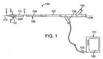
本発明の多くの実施形態では、発電および制御装置は、内部回路400と、制御ソフトウェアと、ユーザ・インターフェース102と、回路400およびユーザ・インターフェース102を収容する発電および制御筺体101とを含んでよい。Power Generation and Control In many embodiments of the present invention, the power generation and control device includes an
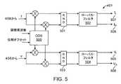
図1および図4を参照すると、筺体101内に収容された内部回路400が、ダイレクト・デジタル・シンセサイザ(DDS)ブロック401を含んでよく、このDDSブロック401のデジタル・コード出力は好ましくは、デジタル/アナログ変換器(DAC)402を通過させることができる。DAC 402は、DDSブロック401からのデジタル・コード信号をアナログ電圧信号414に変換する。電圧信号414およびアナログ変調電圧信号413は好ましくは、増幅器ブロック403を通過し、目標電力出力404がもたらされる。目標電力出力404の電圧負荷および電流負荷の測定は、電圧センサ405および電流センサ407によって測定することができ、電圧センサ405および電流センサ407からの信号は好ましくは、それぞれアナログ/デジタル変換器(ADC)406および408を通過させることができる。ADC 406からのデジタル電圧信号およびADC 408からのデジタル電流信号は好ましくは、ピーク有効電力センサ410によって受信され、このピーク有効電力センサ410で、電力供給目標404上の発電および制御装置の有効電力出力をリアルタイムに測定することができる。電力設定点制御409は、ソフトウェアによってプログラムされた運転パラメータに基づく。 With reference to FIGS. 1 and 4, an
図5および図6に示された好ましい一実施形態では、ピーク有効電力センサ・ブロック410は、(406からの)電圧センス信号Vと(408からの)電流センス信号Iを混合して、DCベースバンド信号にして、好ましくはローパス・フィルタ502で電圧出力を、またローパス・フィルタ504で電流出力を生成するために使用されるDDS 500を備えてよい。ピーク有効電力センサ・ブロック410からの電圧出力および電流出力は、同相電流507成分と、同相電圧成分505と、直交電流成分508と、直交電圧506成分とを含む。回路410内のブロックがその結果、瞬間振幅、周波数信号、ならびに信号の成分間および回路410のブロックを通過するいくつかの信号間の位相シフトを認識できるので、回路410内の信号が同相成分と直交成分とを備えるのが好ましい。次いで、ピーク有効電力センサ410のローパス・フィルタ502およびローパス・フィルタ504からのデジタル出力信号は、図6に示された電力計算回路に送信されてよい。 In a preferred embodiment shown in FIGS. 5 and 6, the peak active
次に図6を参照すると、電圧振幅は、同相電圧信号505と直交位相電圧信号506の二乗を合計し、和を平方根回路602を通過させることによって計算することができる。電流振幅は、同相電流信号507と直交電流信号508の二乗を合計し、和を平方根回路606を通過させることによって計算することができる。未補正の電力は好ましくは、電圧振幅と電流振幅を掛けることによって計算することができる。 Referring now to FIG. 6, the voltage amplitude can be calculated by summing the squares of the in-
電圧信号の位相は好ましくは、電圧信号の直交成分506および電圧信号の同相成分505を逆タンジェント・ゲート603に通すことによって計算することができる。同様に、電流信号の位相は好ましくは、電流信号の直交成分508および電流信号の同相成分507を逆タンジェント・ゲート607に通すことによって計算することができる。コサイン・ゲート608は好ましくは、力率補正を計算できるように逆タンジェント・ゲート603および607から差分出力を受信する。ピーク有効電力は、未補正の電力にコサイン・ゲート608の出力を掛け、ゲート609で結果を丸めることによって計算することができる。 The phase of the voltage signal can preferably be calculated by passing the
図5および図6は最も好ましい一実施形態を示しているが、ピーク有効電力は、瞬間RF電圧波形とRF電流波形を掛けて、結果として生じる信号を積分して、平均値を得るなどの他の手段;使用される電力のタイプに適しており、また本明細書に開示され述べられた装置の回路を備えるコンポーネントに適している任意の使用可能な手段から選択されるピーク有効電力を計算する手段を使用して計算することができる。 5 and 6 show one most preferred embodiment, the peak active power is multiplied by the instantaneous RF voltage waveform and the RF current waveform, and the resulting signal is integrated to obtain an average value, etc. Calculating a peak active power selected from any available means suitable for the type of power used and suitable for the components comprising the circuit of the device disclosed and described herein. It can be calculated using means.
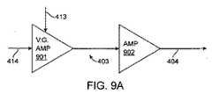
次に図9Aおよび図9Bを参照すると、増幅器ブロック403が、DDSブロック400から電圧入力414を受信し、PIDコントローラ411からの電圧信号413を変調する可変利得増幅器901と、電力増幅器902とを含み得る。電力増幅器902は、図9Bに示された「ソフト電流リミット」を有し、それによって、使用可能な出力電圧は、必要な出力電流が増加するにつれて、場合に応じたやり方で(in a tailored manner)減少する。ソフト電流リミットを有する電力増幅器902の利点は、供給される最大出力電力を電流リミット回路の特性によって本質的に制限できることであり、最も好ましくは約10倍の負荷インピーダンスを超える幅広い範囲の負荷インピーダンスに渡って実質的に一定の最大使用可能出力電力を提供することができる。ソフト電流リミット方式の追加の利点は、スイッチ・モード電源技術を使用して実装される場合、好ましくは約10倍の負荷インピーダンスを超える幅広い範囲の負荷インピーダンスに渡って極めて高い電力増幅器の効率を達成できることである。 Referring now to FIGS. 9A and 9B,
目標電力出力404の制御は、好ましくは、PIOコントローラ411に信号を送出する電力設定点制御409と、ピーク有効電力センサ・ブロック410を介して行われる。このPIDコントローラ411は、最終的に増幅器ブロック403に供給される変調電圧信号413を生成することができる。電力出力設定点制御409は、プログラムされた運転パラメータに基づいてソフトウェア制御信号を供給することができ、この運転パラメータは、多くの実施形態において、周囲の健康な組織への損傷を回避するやり方で病変組織のリモデリングを促すように設定されてよい。電力出力404で同相および直交のリアルタイム負荷測定を行うことにより、回路400はそれによって、負荷変化を特徴付け、設定点から比較的に小さい範囲内で出力が変化し得るように出力を変調することによって負荷変化に応答することができる。しかし、設定点付近での電力出力の変化は、約±2%であってよいが、好ましい実施形態は、約±5%、約±10%、約±15%および約±20%以上など、他の範囲で出力変化を調整してもよい。 Control of the
次に図4および図7を参照すると、PIDコントローラ411は好ましくは、電力出力設定点409およびピーク有効電力出力ブロック410から出力信号を受信する。PIDコントローラ411は好ましくは、比例701(「P」)、積分702(「I」)および微分703(「D」)の計算、それぞれKpe(t)、4 and 7, the

上式において、
Kpe(t)は、所望の電力に対する測定/計算された電力の誤差への比例反応を表し、
In the above formula,
Kp e (t) represents the proportional response to the error of the measured / calculated power for the desired power,
Kdde(τ)dtは、所望の電力に対する測定/計算された誤差の変化率への微分反応を表す。
Kd de (τ) dt represents the differential response to the rate of change of the measured / calculated error for the desired power.
最も好ましい実施形態では、PID方程式は、より一般的な「標準とされる式」または「業界で使用されている式」 In the most preferred embodiment, the PID equation is a more general "standard formula" or "industry used formula"
好ましい一実施形態では、約160マイクロ秒の時間間隔「t」は、目標電力出力404における電力の測定と計算の間に存在する。411のPID制御ループの出力計算は、「操作された変数」または変調電圧414と呼ばれることがあり、この変調電圧414は好ましくは、出力電力を設定点付近に調整するように増幅器ブロック403を駆動するために使用される。定数Ki、KpおよびKdは、回路400が出力404の誤差の増加にどれほど迅速に応答できるか、または設定点409と比較して、404で出力の誤差を減少させるように増幅器ブロック403をどれほど迅速に変調できるかを定義するのに役立つ。電力計算704は好ましくは、DDSブロック401の直交電圧成分506および同相電圧成分505、ならびに直交電流成分507および同相電流成分508に基づく。In a preferred embodiment, a time interval “t” of about 160 microseconds exists between the measurement and calculation of power at the
次に図1および図8を参照すると、筺体101の発電機および制御装置と、接続された付属品100’(たとえば図1のカテーテル・アセンブリ108とコネクタ103とを備えてよい)の両方を含む装置全体100は、図8に示されたものなどの通信方式を使用することができる。図8は2端子回路800を使用する好ましい一実施形態を示しているが、所与の電力制御応用に望ましい構成に応じて他の数の端子を使用してもよい。一般に、電圧センサ405と電流センサ407と標的負荷(組織)404の間に著しいRF損失、反射および位相シフトが通常存在する。これらのRF損失、反射および位相シフトは、負荷(組織)404に供給された実際の電力に著しい偏差を引き起こし、さらに、負荷(組織)インピーダンスの測定に著しい誤差を引き起こす。好ましい一実施形態では、一般化された2端子反射率測定は、負荷(組織)電力を正確に制御することと、負荷(組織)インピーダンスを正確に測定することの両方に関して、RF経路におけるすべてのRF損失、反射および位相シフトを補償するために使用される。このために、2端子回路800は、筺体101の発電機および制御装置と、接続された付属品100’と、目標電力出力404上の負荷との間の入射電力波および反射電力波を使用した一連の制御計算を備えてよく、好ましくは、筺体101の発電機および制御装置によって電圧および電流出力800V&Iが制御されることになる。 Referring now to FIGS. 1 and 8, including both the generator and controller of the
入射電力波は、添字に「an」で示されて、反射電力波は、添字「bn」で示され、404上の入射電力および反射電力は、それぞれ「aL」および「bL」で示される。図8に表された数学操作についての下記の説明において明確にする目的により、数学的方程式では、記載された方程式の意味を簡単にするために、図8に示された記述要素番号「800」を省略するものとする。Incident power wave is indicated by "an" subscript, reflected power wave is indicated by the subscript "bn", the incident and reflected power on 404, are "aL" and "bL" Indicated by For purposes of clarity in the following description of the mathematical operations depicted in FIG. 8, in mathematical equations, the descriptive element number “800” shown in FIG. 8 is used to simplify the meaning of the described equations. Shall be omitted.
入射電力波および反射電力波(それぞれanおよびbn)に関して散乱パラメータの2端子回路は、下記のように定義される。2-terminal circuit scattering parameters for incident power wave and the reflected power wave (an and bn, respectively) is defined as follows.
展開された数式と共に2端回路のS−パラメータ行列は、下記の通り定義することができる。 The S-parameter matrix of the two-end circuit along with the developed mathematical formula can be defined as follows.
b2=S12a1+S22a2 7.
b2 = S12 a1 + S22 a2 7.
回路400を備え得る発生器101、および負荷404の複素インピーダンスは、それぞれロー(ρ)およびガンマ(Γ)として定義することができる。次いで、ローとガンマは好ましくは、下記の通り、反射電力波および反射電力波を使用して定義することができる。 The
次にロー空間からガンマ空間への逆変換は、下記に示されたように、数式1から数式9における関係を使用して導出することができる。 The inverse transformation from low space to gamma space can then be derived using the relationships in Equations 1-9 as shown below.
数式18は、ロー空間からガンマ空間への逆変換の明示的な式を提供している。散乱パラメータは、グループ化され、好ましくは下記の式で、逆変換係数A、BおよびDとして定義することができる。
A=S11 19.
B=S122−S11S22 20.
D=−S22 21.Equation 18 provides an explicit equation for the inverse transformation from low space to gamma space. The scattering parameters are grouped and can be defined as inverse transform coefficients A, B and D, preferably with the following equations:
A = S11 19.
B = S122 −S11 S22 20.
D = −S22 21.
数式18は、係数A、BおよびDを、逆変換の好ましい明示的な式に代入して、それによって、逆変換の好ましい一般的な式を提供することによって単純化することができる。 Equation 18 can be simplified by substituting the coefficients A, B, and D into the preferred explicit expression for the inverse transform, thereby providing a preferred general expression for the inverse transform.
数式22を使用し、ガンマについて解き、順方向変換を好ましい形で導出することができる。
ρ+DΓρ=A+βΓ 23.
DΓρ−BΓ=A−ρ 24.
Γ(Dρ−B)=A−ρ 25.Equation 22 can be used to solve for gamma and to derive the forward transform in a preferred way.
ρ + DΓρ = A + βΓ23.
DΓρ−BΓ = A−ρ 24.
Γ (Dρ−B) = A−
数式19から数式21の同じように、順方向変換係数A’、B’およびD’は好ましくは、下記に示されたようにガンマ空間とロー空間の間の数式を単純化する働きをすることができる。 As with Equations 19-21, the forward transform coefficients A ′, B ′ and D ′ preferably serve to simplify the equation between the gamma space and the low space as shown below. Can do.
数式12は、A’、B’およびD’を、順方向変換の好ましい明示的な式に代入して、それによって、順方向変換の好ましい一般的な式を提供することによって単純化することができる。 Equation 12 can be simplified by substituting A ′, B ′, and D ′ into a preferred explicit expression for forward transformation, thereby providing a preferred general expression for forward transformation. it can.
負荷404の順方向電力は好ましくは、負荷404に入射する電力波の二乗の大きさとして定義することができる。
PFL=|aL|2=|b2|2 32.The forward power of the
PFL = | aL |2 = | b2 |2 32.
同様に、負荷404からの逆方向電力は、負荷404によって反射された電力波の二乗の大きさとして定義することができる。
PRL=|bL|2=|a2|2 33.Similarly, the reverse power from the
PRL = | bL |2 = | a2 |2 33.
上記に定義された関係によって、目標電力出力負荷404で吸収される電力は、下記の関係により、入射電力から反射電力を引いた値として定義することができる。
PL=PAL−PRL 34.
PL=|aL|2−|bL|2 35.With the relationship defined above, the power absorbed by the target
PL = PAL −PRL 34.
PL = | aL |2 − | bL |2 35.
PL=|aL|2{l−|Γ|2} 37.
PL=PFL{1−|Γ|2} 38.
PL=|b2|2(1−|Γ|2) 39.
PL=|S12a1+S22a2|2(1−|Γ|2) 40.
PL = | aL |2 {l− | Γ |2 } 37.
PL = PFL {1- | Γ |2 } 38.
PL = | b2 |2 (1- | Γ |2 ) 39.
PL = | S12 a1 + S22 a2 |2 (1- | Γ |2 ) 40.
最も好ましい2端子回路では、次に、端子1の入射電力および反射電力を定義することができる。800a1の入射電力は好ましくは、800a1に入射する電力波の二乗の大きさとして定義することができ、
PF1=|a1|2 41.
また、800b1の入射電力は好ましくは、800b1で反射された電力波の二乗の大きさとして定義することができる。
PR1=|b1|2 42.In the most preferred two-terminal circuit, the incident power and reflected power at
PF1 = | a1 |2 41.
Also, the incident power at 800b1 can preferably be defined as the magnitude of the square of the power wave reflected at 800b1 .
PR1 = | b1 |2 42.
端子1(「P1」)で吸収された電力は、数式41および数式42を使用して、端子1の入射電力から端子1の反射電力を引いた値として定義することができ、
P1=|a1|2−|b1|2=|a1|2(1−|ρ|2) 43.
上式は、吸収電圧の大きさと、吸収電流の大きさと、吸収電圧と吸収電流の角度のコサインとを掛けた値として定義することもできる。
P1=|V||I||cosφ|=|a1|2(1−|ρ|2) 44.The power absorbed at terminal 1 (“P1 ”) can be defined as the value of the incident power at
P1 = | a1 |2 − | b1 |2 = | a1 |2 (1- | ρ |2 ) 43.
The above equation can also be defined as a value obtained by multiplying the magnitude of the absorption voltage, the magnitude of the absorption current, and the cosine of the angle between the absorption voltage and the absorption current.
P1 = | V || I || cosφ | = | a1 |2 (1- | ρ |2 ) 44.
数式9を数式7に代入し、b2について解くことによって、図8の800b2について定義された下記の関係を定義することができる。
b2−S22a2=S12a1 46.By substituting Equation 9 into
b2 −S22 a2 = S12 a1 46.
次に、図8の負荷404の電力は、数式49を数式39に代入し、数式45を数式51に代入して分子を展開することにより定義することができる。 Next, the power of the
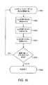
本発明の好ましい一実施形態では、図16を参照して理解できるように、図4の回路400の既知のインピーダンスの測定は、変換係数A、B、DおよびA’、B’、D’を定義するために行うことができる。最も好ましくは、既知の回路負荷404で、3つの測定が行われ、最も好ましくは、インピーダンスZρOは、約1000Ωの負荷で取られ、インピーダンスZρは、約50Ωの負荷で取られ、インピーダンスZρLは、約150Ωの負荷で取られ、ただし、発電機および制御装置101の複素電圧および電流測定(図8の800V&I)は、数式53を使用してインピーダンスZρO、ZρSおよびZρLを計算するために使用され、ただし、SYSTEMIMPEDANCEには、値150Ωが代入される。しかし、ZρO、ZρSおよびZρLを計算するための既知の回路負荷および代入されるSYSTEMIMPEDANCEは、約ゼロ・オームと約無限大オームの間の範囲の他の値で実施することができる。図16に示されたように、こうした較正方法は、発電コンポーネントを標的組織に結合する前に、理想的にはアタッチメント100’を筺体の発電回路400に結合する前に開始してよい1601。3つの異なる負荷がかけられ、各負荷でインピーダンスが取られる1602、1603、1604。これらの測定は、回路400のコンポーネントで取られ、本明細書に述べられたシステム特徴付け計算用のハードウェアおよび/またはソフトウェア・モジュールに入力される。In one preferred embodiment of the present invention, as can be understood with reference to FIG. 16, the known impedance measurement of the
数式53を解くには好ましくは、約1000Ω、約50Ωおよび約150Ωの各々の負荷で好ましくはインピーダンスZΓO、ZΓSおよびZΓLを供給するために、最も好ましくはネットワーク解析を使用して、最も好ましくはベクトル・ネットワーク解析を使用して、予備の1組のインピーダンス測定を行うことを伴い得る。次いで、6つの好ましいインピーダンス測定ZΓO、ZΓS、ZΓL、ZρO、ZρSおよびZρLが好ましくは、変換係数A’、B’、D’を計算するために使用されてよい。To solve Equation 53, most preferably using network analysis to provide preferably impedances ZΓO , ZΓS and ZΓL at each load of about 1000Ω, about 50Ω and about 150Ω, most preferably It may involve making a preliminary set of impedance measurements, preferably using vector network analysis. The six preferred impedance measurements ZΓO , ZΓS , ZΓL , ZρO , ZρS and ZρL may then preferably be used to calculate the transformation coefficients A ′, B ′, D ′.
次に、好ましくは数式54から数式56によって定義された係数の値は好ましくは、数式31を使用して図4の目標電力出力404の実際の負荷インピーダンスを、また数式52を使用して目標電力出力404で印加された実際の電力を計算するために使用することができ、それによって好ましくは、404の出力が負荷のリアルタイムの変化に基づいて設定点付近で正確に調整され、電力供給が、本明細書に述べられた範囲内に維持されるように、PIDコントローラ411からの計算された変調出力電圧413を提供する。 Then, preferably the value of the coefficient defined by Equations 54-56 is preferably the actual load impedance of the
好ましい実施形態では、電力供給点の実際の電力出力は最も好ましくは、出力404で印加された負荷の測定された複素インピーダンス角度に基づく。その場合、負荷は、最も好ましくは組織を示し、複素インピーダンス角度は好ましくは、組織の健康または疾患、および/または装置100を使用している間の組織状態の変化を示す。さらに、インピーダンスはキャパシタンスおよび抵抗の関数であるので、リアルタイム組織キャパシタンスおよびリアルタイム組織抵抗もまた、インピーダンスとキャパシタンスと抵抗の関係によって、測定データに基づいて知ることができる。 In the preferred embodiment, the actual power output at the power supply point is most preferably based on the measured complex impedance angle of the load applied at
インピーダンスが実成分と虚成分とを有し得ることを想起して、数式57における関係は、下記のようにさらに表現し、展開することができる。 Recalling that impedance can have real and imaginary components, the relationship in Equation 57 can be further expressed and expanded as follows.
数式61をC2について解き、数式63を数式62に代入し、数式64をCについて解く。Equation 61 is solved for C2 , Equation 63 is substituted into Equation 62, and Equation 64 is solved for C.
数式65をω2C2R2について解き、数式61に代入することによって、簡略化された関係を得ることができる。By solving
次に、数式66を単純化し、Rについて解くことによって、数式57からのインピーダンスZの既知の値によって、リアルタイムの組織抵抗を決定することができ、 Next, by simplifying Equation 66 and solving for R, real-time tissue resistance can be determined by the known value of impedance Z from Equation 57,
も好ましい実施形態では、図1のシステムまたは装置100全体は、図4の回路400、および結合装置または付属品100’を含んでよく、それらは、治療反応を促すために、組織の特徴付けおよび選択的な治療で共に使用することができる。インピーダンス、イメージング・モダリティおよびエネルギー・モダリティに基づく組織の特徴付けおよび選択的処理は、2007年11月6日に発行された米国特許第7,291,146号、Steinke他、「Selectable Eccentric Remodeling and/or Ablation of Atherosclerotic Material」、および上記に言及された米国出願第11/392,231号、第11/975,651号、第11/617,519号、第11/975,474号、第11/975,383号、12/564,268に記載されており、これらの特許の完全な開示を、参照により本明細書に組み込む。しかし、最も好ましい実施形態では、電力出力は、RFエネルギーであるが、上記言及に開示され述べられた超音波、レーザ、マイクロ波なども、本発明の範囲内である。 In a preferred embodiment, the entire system or
次に図4を参照すると、一部の実施形態では、DDSブロック401、電力出力設定点制御409およびピーク有効電力センサ410は、埋込み型プロセッサなしのフィールド・プログラマブル・ゲート・アレイを備える。フィールド・プログラマブル・ゲート・アレイが内部プロセッサを備える他の実施形態では、DDSブロック401、電力出力設定点制御409、ピーク有効電力センサ・ブロック410およびPIDコントローラは、フィールド・プログラマブル・ゲート・アレイ内に備えられてよい。 Referring now to FIG. 4, in some embodiments, the
一部の実施形態では、発生器および制御装置101は、プロセッサを含んでもよいし、治療を制御または記録するためにプロセッサに結合されてもよい。プロセッサは典型的に、本明細書に述べられた実施形態および方法の一部またはすべて、1つまたは複数を実施するためのマシン読取り可能プログラム命令またはコードを実行する1つまたは複数のプログラマブル処理装置をしばしば含むコンピュータ・ハードウェアおよび/またはソフトウェアを備える。コードは、メモリ(任意選択で読取り専用メモリ、ランダム・アクセス・メモリ、不揮発性メモリなど)、および/または記録媒体(フロッピー(登録商標)・ディスク、ハードドライブ、CD、DVD、不揮発性ソリッドステート・メモリ・カードなど)などの有形媒体でしばしば具現化される。コードならびに/あるいは関連するデータおよび信号は、ネットワーク接続(ワイヤレス・ネットワーク、イーサネット(登録商標)、インターネット、イントラネットなど)を介してプロセッサに、またはプロセッサから送信することもでき、コードのうちの一部またはすべては、カテーテル・システムのコンポーネント間で、また1つまたは複数のバスを介してプロセッサ内で送信することもでき、適切な標準またはプロプラエタリの通信カード、コネクタ、ケーブルなどがしばしば、プロセッサに含まれる。プロセッサはしばしば、少なくとも一部はソフトウェア・コードでプロセッサをプログラミングすることによって、本明細書に述べられた計算および信号送信ステップを実施するように構成されてよく、このソフトウェア・コードは、単一のプログラム、一連の別個のサブルーチンまたは関連プログラムなどとして書くことができる。プロセッサは、標準またはプロプラエタリのデジタルおよび/またはアナログ信号処理ハードウェア、ソフトウェアおよび/またはファームウェアを備えてよく、本明細書に述べられた計算を患者の治療中に実施するのに十分な処理電力を好ましくは有することができ、プロセッサは任意選択で、パーソナル・コンピュータ、ノート型コンピュータ、タブレット・コンピュータ、プロプラエタリの処理装置またはその組合せを備える。現代のコンピュータ・システムに関連する標準またはプロプラエタリの入力デバイス(マウス、キーボード、タッチスクリーン、ジョイスティックなど)および出力デバイス(プリンタ、スピーカ、ディスプレイなど)も含まれてよく、複数の処理装置(さらには別個のコンピュータ)を有するプロセッサが、広範囲の集中型または分散型データ処理アーキテクチャで使用されてよい。 In some embodiments, the generator and
最も好ましい実施形態では、装置100の制御ソフトウェアは、システムの使いやすさ、柔軟性および信頼性をさらに向上させるために、クライアント・サーバ・スキーマを使用することができる。「クライアント」は、システム制御論理であり、「サーバ」は、制御ハードウェアである。通信マネージャは、加入しているクライアントおよびサーバにシステム状態の変化を伝える。クライアントは、現在のシステム状態がどうであるか、および状態の特定の変化に基づいてどんなコマンドまたは決定を実施すべきかを「知る」。サーバは、クライアント・コマンドに基づいてシステム機能を実施する。通信マネージャが集中型の情報マネジャであるので、新しいシステム・ハードウェアは好ましくは、既存のクライアントーサーバ関係の前に変更を必要としないことがあり、次いで、新しいシステム・ハードウェアおよびその関連する制御論理は単に、通信マネージャを介して管理された情報への追加の「加入者」になってよい。この制御スキーマは好ましくは、固定されるベース・ルーチンを備えた堅牢な中央の動作プログラムを有する利点をもたらし、システムで動作するように設計された新しい回路部品を動作させるのにベース・ルーチンへの変更は必要ないことが好ましい。 In the most preferred embodiment, the control software of the
組織治療用の付属品
一部の実施形態では、図1の装置100のシステム全体は、発電装置と共に、接続された付属品をさらに含んでよく、この付属品は最も好ましくは、エネルギー供給表面が備えられた腔内カテーテル108を含んでよい。Accessories for Tissue Treatment In some embodiments, the entire system of the
多くの実施形態では、エネルギー供給表面は好ましくは、間隔を置いて配置された複数の電極112を備えてもよい。図1に示された発電装置101は、好ましくは選択された電極に選択的にエネルギーを与えることを可能にするためにコネクタ103によって複数の電極に動作可能に結合される。 In many embodiments, the energy supply surface may preferably comprise a plurality of spaced apart
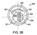
多くの実施形態では、エネルギー供給表面は、バルーンが膨張して管腔の組織などの組織に接触するとき、標的組織内で複数のリモデリング・ゾーンを定義するために、図3Aに示されたように、膨張可能なバルーン200の周りに置かれた複数の電極112を備える。 In many embodiments, the energy delivery surface is shown in FIG. 3A to define multiple remodeling zones within the target tissue when the balloon is inflated to contact tissue such as luminal tissue. As such, it includes a plurality of
次に図1および2を参照すると、組織への所望の温度効果を誘発するカテーテル・システムの例示的な一実施形態が示されている。カテーテル・システムは、近位端107および遠位端111を備えたカテーテル本体109を有するバルーン・カテーテル108を含む。カテーテル体109は、柔軟であり、カテーテル軸113を定義し、ガイドワイヤ管腔206および膨張管腔201など、1つまたは複数の管腔を含んでよい。灌流、液体供給、イメージングなど、他の治療あるいは応用に望ましい場合、さらなる管腔が提供されてもよい。カテーテル108は、遠位端111に隣接した膨張式バルーン200と、近位端107に隣接した筺体106とを含む。筺体106は、ガイドワイヤ管腔206と連通している第1のコネクタ104と、膨張管腔201と流体連通している第2のコネクタ105とを含む。膨張管腔201は、バルーン200と第2のコネクタ105の間に伸びている。第1のコネクタ104と第2のコネクタ105の両方は任意選択で、LUER−LOC(登録商標)コネクタなど、標準のコネクタを備えてよい。遠位端は、ガイドワイヤの通過を可能にする一体型のチップ・バルブなどを含んでよい。 Referring now to FIGS. 1 and 2, an exemplary embodiment of a catheter system that induces a desired temperature effect on tissue is shown. The catheter system includes a
筺体106は、電気コネクタ103を収容することもでき、この電気コネクタ103は好ましくは、それぞれが伝導体203を介して電極112に結合されている複数の電気接続を含んでよい。この構成は好ましくは、電極112にエネルギーを容易に与えることを可能にし、電極はしばしば、囲まれたコントローラおよび電源101によってエネルギーが与えられ、この電源101は好ましくは、単極またはバイポーラRFエネルギー、マイクロ波エネルギー、超音波エネルギーの形、または他のこうした適切な形のエネルギーを生成してよい。こうした一実施形態では、電気コネクタ103は、図4の回路400に結合されており、この回路400はその最も好ましい形では、図3Bに示されたようにエネルギーを電極112に選択的に向けることを可能にできるやり方でRFエネルギーを生成することができる。単極RFエネルギーが使用される場合、患者接地は、たとえば外部電極によって提供されてもよいし、カテーテル本体109上の電極によって提供されてもよい。 The
次に図3Bおよび図1を参照すると、電極112は、好ましくは生物学的反応を開始するためにエネルギーが電極112A、112B、112C、112Dと組織300の間で送信され得るように、好ましくは周囲の組織300と結合される。バルーン200は典型的には、バルーン・カテーテル108の遠位端111を備え、バルーン200の電極112など、エネルギー供給表面は一般に、カテーテル108の近位端107に結合されたエネルギー源を使用してバルーン200上でエネルギーが与えられる。エネルギー導管203は、近位端107とバルーン200の間でカテーテル本体109に沿って伸びてよく、エネルギー導管203は、RFエネルギーなどを印加するための電気伝導体、あるいはレーザや他の光エネルギーを伝えるためにカテーテル本体内で管腔に沿って進む光ファイバー・フィラメントなど光伝導体などをしばしば備える。 Referring now to FIGS. 3B and 1, the
図3Bに示されたように、電極112は好ましくは、バルーン200の周辺に位置してよい。エネルギー301、最も好ましくはRFエネルギーは、最も好ましい実施形態では、隣接した電極対112Aと112C、または112Aと112D、あるいは電極112A〜112Dの任意の組合せに向けられてよく、周囲の組織300内の組織の健康な部分303と組織の疾患部分302の両方を治療する。この構成は好ましくは、エネルギー経路301を作成し、このエネルギー経路301は、特定の治療ゾーンまたはセグメント内のエネルギーまたは熱(「組織リモデリング・エネルギー」)を、特定の深さの電極対112A〜112Dの間の容積を有する電極対112A〜112D間の組織300(「リモデリング・ゾーン」)に伝えることができる。電極対112A〜112Dの様々な組合せの使用は、重複した対を使用することによってリモデリング・ゾーン間のギャップを減少させ、または取り除くことができる。電極対112A〜112Dをバイポーラ・エネルギーと共に使用することは好ましくは、それによって、単極手法と比べて向上した性能を提供することができる。病変組織302は、健康な組織303より高い抵抗率を有すると知られている。単極のシステムで、112Aと112Bなどの電極対112を使用することによって、組織リモデリング・エネルギーは好ましくは、リモデリング・ゾーンを作成できるように健康な組織303、病変組織302またはその組合せを通過することができる。任意の数のリモデリング・ゾーンを作成するために、任意の数の電極112を様々なパターンまたはアレイで使用することができる。発電機および制御装置101は、一定の電力、一定の電圧、一定の電流を印加してもよいし、一定温度を生成するように変調してもよく、そのいずれもが、組織のタイプおよび所望の治療効果に最も有利である。 As shown in FIG. 3B, the
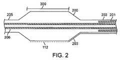
図2に、バルーン200がより詳細に示されている。バルーン200は一般に、膨張管腔201に結合された近位部分202と、ガイドワイヤ管腔206に結合された遠位部分205とを含む。バルーン200は、液体またはガスで膨張されたとき、放射状に拡張する。一部の実施形態では、バルーン200は、組織300に接触するように加圧される低圧バルーンであってよい。他の実施形態では、バルーン200は、組織300を熱することと、組織300管腔を膨張させることの両方のために圧力の上昇が可能な血管形成術用バルーンであってよい。バルーン200は、特に使用後に取り除くために、放射状に拡張した膨張した構成から低プロファイルの構成へとバルーンを再構成することを容易にする折り目を有する準拠型または非準拠型のバルーンを備えてよい。 In FIG. 2, the
電極112は、バルーン200の表面に取り付けられ、関連する伝導体203が電極112から近位に伸びる。電極112は、バルーン200上に、多くの異なるパターンまたがアレイで配置することができる。このシステムは、エネルギーの単極またはバイポーラ印加に使用することができる。単極エネルギーの供給では、接地電極は、カテーテル108のシャフト上で使用されてもよいし、接地電極パッドなど、患者の皮膚上で使用されてもよい。バイポーラ・エネルギーの供給では、隣接した電極112は、バイポーラ・エネルギーを隣接した周囲の(軸方向にオフセットされた)電極112間に向けることを可能にするように軸方向にオフセットされてよい。他の実施形態では、電極112は、バイポーラ・エネルギーを隣接した遠位の電極112と近位の電極112の間に向けることを可能にするように、バルーン200の周りの帯に配列することができる。
組織感知および治療エネルギー量の選択的供給
多くの実施形態では、電極112は、好ましくは治療結果を達成するために、標的となる組織300、302、303を評価し選択的に治療するためにエネルギーが与えられてよい。たとえば、インピーダンス測定を用いて組織治療領域を識別するために、組織シグニチャが使用されてよい。図3Bに示されたものなど、管腔内で周囲に間隔を置いて配置された電極112を利用したインピーダンス測定を使用して、組織300、302、303を解析することができる。隣接した電極112対の間(および/または分離された電極112A〜112D対の間)のインピーダンス測定は、電流路が病変組織302を通り抜ける場合、および電流路がたとえば管腔の壁の健康な組織303を通り抜ける場合には異なることがある。したがって、病変組織302の両側の電極112間のインピーダンス測定によって病変を示すことができ、隣接した電極112の他の対の間の測定によって健康な組織303を示すことができる。インピーダンス測定と併せて、またはその代替物として血管内超音波、光コヒーレンス断層撮影法など、他の特徴付けを使用して、治療すべき領域を識別することができる。一部の場合では、組織シグネチャおよび/またはシグネチャ・プロファイルは人によって異なることがあるので、好ましくは隣接した組織を区別する助けとするために、治療すべき組織300、302、303のベースライン測定を得ることが望ましいことがある。さらに、組織シグネチャおよび/またはシグネチャ・プロファイル曲線は、それぞれ異なる組織間の関連した傾斜、オフセットなどの識別を容易にするように正規化することができる。その完全な開示が参照により本明細書に組み込まれる、2006年10月18日に出願された米国特許出願第60/852,787号、「Tuned RF Energy and Electrical Tissue Characterization For Selective Treatment Of Target Tissues」、2007年4月4日に出願された米国仮出願第60/921,973号、「Tuned RF Energy and Electrical Tissue Characterization For Selective Treatment Of Target Tissues」に開示された技法のいずれかを、本発明と組み合わせることができる。Tissue Sensing and Selective Supply of Treatment Energy In many embodiments, the
発電機および制御装置101は、約1秒から約180秒の間、約0.001のワットから50ワットの範囲、約0.25ワットから5ワットの平均電力の好ましい例示的な範囲で、または約4ジュールから約45ジュールで電極112に選択的にエネルギーを与えるために使用することができる。より高いエネルギーの治療は、約0.5ワットで約90秒間、または約0.25ワットで約180秒間など、より低い電力でより長い継続時間で行われる。2ワットから4ワット範囲のほとんどの治療は、約1秒から約4秒で実施される。より広い電極112間隔を使用する場合、治療の平均電力および継続時間を拡大することが望ましく、その場合に、平均電力は、約5ワットより高くなることがあり、エネルギーの合計は、約45ジュールを超えることがある。同様に、より短く、またはより小さい電極対112A〜112Dを使用する場合、平均電力を縮小することが望ましく、またエネルギーの合計は、約4ジュール未満であり得る。電力および継続時間は、大きい損傷を引き起こすものより小さくなるように、最も好ましくは、特に血管内の病変組織を焼灼できるほど小さくなるように構成される。 The generator and
標的組織の所望の加熱を行い、かつ/または側副組織への加熱を制限するのに適した電力範囲は、電極112(または他のエネルギー伝達表面)ジオメトリにエネルギーが印加される時間などに、少なくとも一部依存することがある。まず、本明細書に述べられた治療を電極で組織に適用する場合、特に本明細書に述べられた範囲内の電力を印加するとき、所望の範囲外の電圧および/または電流を適用する必要性を回避するために、回路内に組織に好ましい負荷インピーダンスがあってよい。適切な負荷インピーダンス範囲は一般に、約20オームから約4500オームの範囲内にあり、より典型的には約40オームから約2250オームの範囲にあり、好ましくは約50オームから約1000オームの範囲にある。 A power range suitable for providing the desired heating of the target tissue and / or limiting heating to the collateral tissue, such as the time that energy is applied to the electrode 112 (or other energy transfer surface) geometry, such as May depend at least in part. First, when applying the treatment described herein to tissue with an electrode, it is necessary to apply a voltage and / or current outside the desired range, particularly when applying power within the range described herein. In order to avoid sexuality, there may be a preferred load impedance for the tissue in the circuit. Suitable load impedance ranges are generally in the range of about 20 ohms to about 4500 ohms, more typically in the range of about 40 ohms to about 2250 ohms, preferably in the range of about 50 ohms to about 1000 ohms. is there.
電極のジオメトリおよび極性が、回路内に有効に含まれた組織のジオメトリに影響を及ぼすので、回路内の組織の負荷インピーダンスは、組織の特性に、たとえば組織に係合する(engage)電極のジオメトリにも依存することがある。エネルギーが向けられる組織は、約0.2ジーメンス/mから約0.5ジーメンス/mの範囲の比伝導率を有することがある。それぞれ異なるタイプの病変組織がそれぞれ異なる範囲の比伝導率を有することがあり、あるタイプの病変組織は約0.2ジーメンス/mから約0.35ジーメンス/mの範囲の比伝導率を有し、他は、約0.35ジーメンス/mから約0.5ジーメンス/mの範囲内にある。 Since the geometry and polarity of the electrode affects the geometry of the tissue that is effectively contained in the circuit, the load impedance of the tissue in the circuit can affect the characteristics of the tissue, for example, the geometry of the electrode that engages the tissue. May also depend on. The tissue to which energy is directed may have a specific conductivity in the range of about 0.2 Siemens / m to about 0.5 Siemens / m. Different types of diseased tissue may have different ranges of specific conductivity, and certain types of diseased tissue have specific conductivities in the range of about 0.2 Siemens / m to about 0.35 Siemens / m. , Others are in the range of about 0.35 Siemens / m to about 0.5 Siemens / m.
治療の所望の電力、エネルギーおよび時間は同様に、相互関連しており、少なくとも電極112のジオメトリに関連することもある。非常に一般的に述べると、より低い電力の治療を長時間適用すると、総エネルギーが比較的に高い治療となる傾向があり、より高い電力の治療をより短い時間で行うと、エネルギーが低下した治療となる傾向がある。より具体的には、比較的低い平均電力(1W以下)では、治療当たりの総エネルギー供給は、約8ジュールから約45ジュールの範囲であり得る。より高い電力(1W超)では、治療当たりの総エネルギー供給は、約4ジュールから約15ジュールの範囲であり得る。電極間隔が2倍になった場合、電力は4倍増加し得る。組織に伝達される電力は、しばしば電力およびエネルギー密度を所望の範囲に維持するために、特定の電極構成に合わせて較正およびスケーリングされてよい。例示的な電力範囲は、たとえば約1ワットから約5ワットであってよい。より低い電力設定の継続時間は典型的に、約1秒から約8秒まで変化する。さらに、約10秒より遥かに長い継続時間を使用して、約1ワット未満の非常に低い電力設定も可能である。 The desired power, energy, and time of treatment are also interrelated and may be related at least to the geometry of the
電極112の構成を変えることによって電力設定を大幅にスケーリングすることも可能である。たとえば、電極112の内側エッジ間距離が増加する場合、組織の容積がおよそ4倍大きくなるので、およそ4倍の電力を印加してよい。したがって、本明細書に述べられた例示的な実施形態と異なる電極構成を、約4ワットから約20ワットの電力範囲内で使用することができる。電極112を短くし、したがってリモデリング・ゾーンの容積を短くし減少させることによって、組織容積に印加するのに適した電力の大きさにも影響を及ぼす。 It is also possible to scale the power setting significantly by changing the configuration of the
この複雑な1組の関係を定量化し、例示的な装置が動作できる空間を制限するために、これらのパラメータのうちのいくつかの安全な値の間の経験的関係を生成し、テーブルの形で、または数学的な関係によってグラフィカルに示すことができる。特に有利な関係を表す例示的な数式は、下記の通りである。
電力=bx2Lt-0.59
ただし、bは、0.2から0.6の範囲内のパラメータであり、xは、電極112のミリメートル単位の内側エッジ間の間隔であり、Lは、電極112のミリメートル単位の電極112の長さ(またリモデリング・ゾーンの近似の長さ)であり、電力はワット単位であり、秒単位の時間であり、bは、(ワット/mm3)*(秒0.59)の単位を有する。この数式によって表された範囲内の例示的な治療は、4ワットを2秒間、3ワットを3秒間の、2ワットを4秒間、および1ワットを12秒間などの治療を含む。In order to quantify this complex set of relationships and limit the space in which the exemplary device can operate, an empirical relationship between several safe values of these parameters is generated, Or graphically by mathematical relationships. An exemplary mathematical expression representing a particularly advantageous relationship is as follows:
Power = bx2 Lt-0.59
Where b is a parameter in the range of 0.2 to 0.6, x is the spacing between the inner edges of the
回路400の較正は、既知の回路負荷404で3つの測定を行うことによって実施することができ、最も好ましくは、約1000Ωの負荷でインピーダンスZρOが取られ、約50Ωの負荷でZρSが取られ、約150Ωの負荷でZρLが取られ、ただし、発電機および制御装置101の複素電圧および電流測定(図8の800V&I)は、インピーダンスZρO、ZρSおよびZρLを計算するために使用される。好ましい較正方法は、本明細書に開示され述べられたようにインピーダンスが組織特徴付けおよび治療制御の手段を提供するように、組織の治療前および治療中にインピーダンスの正確なリアルタイム測定を可能にすることができる。Calibration of the
装置100の較正は、接続された付属品のタイプを、そのインピーダンス特性に基づいて確認するための較正を繰り返すことによって、装置に接続された付属品を識別するステップをさらに備えてよい。たとえば、接続された付属品が、さらに電極112で構成されたカテーテル108を備える図1では、存在する電極112の数は、コネクタ103によって発電機および制御装置102に動作可能に接続されたカテーテル108内の電極回路(図2に示された電極112および伝導体203など)の数を多重感知することによって決定することができる。図1、図4、図8および16図をもう一度参照すると、付属品100’(典型的にはカテーテル108)なしの発電機回路400の較正の後、カテーテルは、発電機回路1603に接続されてよく、装置全体100の3つのインピーダンス測定を再び行うことができる。 Calibration of the
いくつかの利点は、好ましくは較正を自動的に再実施することによって得ることができる。たとえば、回路400の様々な要素などの単一のサブコンポーネントではなく、装置アセンブリ100全体を較正させることによって、負荷404で取られたインピーダンス測定は、接続された付属品に関係なく、組織特徴付けおよび電力制御の正確な指標のままとなり得る。さらに、接続された付属品の感知された構成は、電極112の様々な種類の構成の依存性が、本明細書に開示され述べられた好ましい継続時間およびエネルギー供給パラメータに対応し得るように、プログラムされた治療ルーチンに対応してよい。さらに、接続された付属品の認識を事前にプログラミングすることによって、付属品の不適切な使用、または互換性のないアタッチメントの使用を防止する。さらに、接続された付属品のタイプを検出できることによって、滅菌、または他の機器のオペレーションとインターフェースする間に劣化し得る無線周波数識別など、他の識別方法に付随する合併症を回避する堅牢で単純な付属品識別方法を可能にすることができる。さらに、自己識別方法によって、ユーザ・コマンドの必要性を減少させ、または取り除き、それによって、使いやすさを向上させ、ユーザと装置の間の言語障壁などの問題を最小限に抑えることができる。さらに、グラフィカル・ユーザ・インターフェース102の使用は、言語依存性を取り除き、または減少させ、使いやすさを向上させるためのさらなる手段として使用することができる。 Several advantages can be obtained, preferably by automatically re-calibrating. For example, by having the
多くの実施形態では、発電および制御装置101は、設定された限界より上または下になるとシステムが自動的にシャット・ダウンし得るように、電力供給目標404で測定されたインピーダンス値の範囲内で動作するようにプログラムすることができる。たとえば、装置101は、最も好ましい約50オームから約500オームの範囲を有する、約5オームから約1000オームの負荷インピーダンスの範囲に渡って動作するようにプログラムすることができ、範囲の下限は、健康でありまたは組織に応答し得る組織を示唆することができ、範囲の上限は、組織の不十分な電気的接触または破壊を示唆することができる。インピーダンス制限がプログラムされることによって、エネルギーが所望の投与量を超えて制御されずに位置に印加されることを回避する際のさらなる防止策となるという利点をもたらすことができる。 In many embodiments, the power generation and
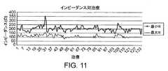
図10〜図13は、図1の装置アセンブリによって制御され供給される弱い加熱を用いた典型的な組織治療における電流、インピーダンス、電圧、位相角および電極電力反応をそれぞれ示している。図13では、標的で測定された電力が、発生器の電力出力と比較して示されている。 FIGS. 10-13 illustrate current, impedance, voltage, phase angle and electrode power response, respectively, in a typical tissue treatment using weak heating controlled and supplied by the device assembly of FIG. In FIG. 13, the power measured at the target is shown relative to the power output of the generator.
本明細書に述べられた血管治療デバイス、システムおよび方法の実施形態は、弱いまたは標準の拡張と組み合わせた弱い加熱によってアテローム性動脈硬化の疾病を治療するために使用することができる。たとえば、電極112を配置されている血管形成術用バルーン・カテーテル構造108は、標準の非加熱の血管形成膨張圧力の、またはそれより著しく低い拡張圧力と任意選択により組み合わせて、拡張前、拡張の間および/また拡張後に血管壁に電位を印加してよい。約10気圧から約16気圧のバルーン200膨張圧が、たとえば特定の病変の標準の血管形成拡大に適し得る場合、本明細書に述べられたバルーン200上の柔軟な回路電極112、203、バルーン構造200上に直接置かれた電極112などを通る適切な電位と組み合わされた修正型の拡張治療は、約10気圧から約16気圧を使用してもよいし、約6気圧以下の圧力、また恐らくは約1気圧から約2気圧と同じくらい低い圧力で行われてもよい。こうした適度な拡張圧力は、組織特徴付け、調整されたエネルギー、偏心治療、の1つまたは複数の態様、および血管の疾病の治療について本明細書に述べられた他の治療態様の1つまたは複数の態様と組み合わせてもよいし、組み合わせなくてもよい。 Embodiments of the vascular treatment devices, systems and methods described herein can be used to treat atherosclerotic disease with weak or weak heating combined with standard dilation. For example, the angioplasty
多くの実施形態では、血管の拡張前、拡張の間および/または拡張後に加えられた弱い加温エネルギーによって、合併症を減少させながら拡張効果を高めることができる。一部の実施形態では、バルーン200を用いたこうした制御された加温によって、反動の減少が示され、インプラントの欠点なしにステントライクな拡張の利点の少なくとも一部を提供することができる。加熱の利点は、血管外膜層の加熱を有害反応しきい値より下に制限することによって向上され、かつ/または合併症が抑制され得る。多くの場合、血管内膜および/または血管媒体のこうした加熱は、約10秒未満、しばしば約3秒(さらには2秒)未満である加熱時間を使用して提供することができる。他の場合では、非常に低い電力を、より長い継続時間の間、使用してよい。回路の駆動電位を標的組織位相角に一致させることでエネルギー301を標的組織300、302、303に効率的に結合することによって、所望の加熱効率を向上させて、電力曲線より下の領域を有効に最大化することができる。位相角の一致は絶対的である必要はなく、特徴付けられた標的組織に位相が完全に一致することには利点があり得るが、代替なシステムは、典型的な標的組織に実質的に一致するように適切な電位を事前に設定することができ、実際の位相角に厳密には一致し得ないが、標的組織内の加熱の局所化は、標準の電力形式を使用するよりも著しく向上され得る。 In many embodiments, weak warming energy applied before, during and / or after dilatation of blood vessels can enhance dilation effects while reducing complications. In some embodiments, such controlled warming with the
リモデリングは、最も好ましくはRFの形であるが、マイクロ波および/超音波エネルギーの形でも電極112にエネルギーを印加することなどを伴い得る。このエネルギーは、標的および/または側副組織の温度を制限し、たとえば脆弱なプラークの線維性被膜または動脈構造の内膜層の加熱を制限するために制御される。 Remodeling is most preferably in the form of RF, but can also involve applying energy to the
一部の実施形態では、表面組織の温度範囲は、約50℃から約90℃である。弱い加熱では、組織表面温度は、約50℃から約65℃に変化し得るが、より強い加熱では、表面組織の温度は、約65℃から約90℃の範囲であってよい。バルク組織温度がほとんど約50℃から約55℃未満にとどまるように免繊維性被膜や内膜層など他の組織の加熱を約50℃から約65℃の範囲内の組織表面温度未満に抑制しながら脂質プールの溶解を誘発するのに十分なほどに、脆弱なプラークの脂質に富んだプールの加熱を制限することによって、さもなければ再狭窄などにつながり得る免疫反応を抑制することができる。約50℃と約65℃の間の比較的に温和な表面温度は、より血管腔を大きくし、血流を改善するための治療に対する組織の治癒反応によって、治療中、治療の直後、および/または治療の1時間超後、1日超後、1週間超後、さらには1ヶ月超後にタンパク質結合を変性させ断つのに十分であり得る。 In some embodiments, the temperature range of the surface texture is from about 50 ° C to about 90 ° C. With weak heating, the tissue surface temperature can vary from about 50 ° C. to about 65 ° C., but with stronger heating, the surface tissue temperature can range from about 65 ° C. to about 90 ° C. Suppresses heating of other tissues, such as fiber-free coatings and intimal layers, to below the tissue surface temperature in the range of about 50 ° C. to about 65 ° C. so that the bulk tissue temperature stays at about 50 ° C. to less than about 55 ° C. However, by limiting the heating of the fragile plaque lipid-rich pool sufficient to induce lipid pool lysis, immune responses that would otherwise lead to restenosis and the like can be suppressed. A relatively mild surface temperature between about 50 ° C. and about 65 ° C. can be achieved during treatment, immediately after treatment, and / or by the healing response of the tissue to treatment to enlarge the vessel lumen and improve blood flow. Or it may be sufficient to denature and break protein binding after more than 1 hour, more than 1 day, more than 1 week, and even more than 1 month after treatment.
本明細書に述べられた方法およびデバイスは、血管の組織治療において選択的ではないが、装置100は、アテローム性動脈硬化症が時間の50%を超えて、恐らくはケースの75%(さらには75%超)の程度まで血管の軸に対して偏心していることがあるので、同心的と偏心的の両方のアテローム性動脈硬化症の治療に使用することができる。 Although the methods and devices described herein are not selective in vascular tissue treatment, the
したがって、アテローム性動脈硬化物質のリモデリングは、アテローム性動脈硬化および他の収縮、融解などを備え得る。動脈の層の内のアテローム性動脈硬化物質は、変性させ、融解することができ、かつ/または治療は、血流を改善するために性動脈硬化物質の収縮および/または動脈層内の生物活性の付与を伴い得る。本発明は、偏心性病変を備え得る脆弱なプラークまたは脆弱なプラークが関係する血管の治療に特定の利点をもたらすこともできる。本発明は、脂質に富んだプラークのリモデリング、変性、融解、収縮および/または再分配を行うために、キャップの肥厚化を誘発し、プラークの破裂に対する脆弱さを減少させるためにキャップ構造を弱く加熱し、かつ/または脆弱なプラークの脂質に富んだプールを加熱することにも応用される。 Thus, atherosclerotic material remodeling may comprise atherosclerosis and other contractions, melting, and the like. Atherosclerotic material within the arterial layer can be denatured and melted, and / or treatment can cause atherosclerotic material contraction and / or biological activity within the arterial layer to improve blood flow. May be accompanied by The present invention may also provide particular advantages in the treatment of vulnerable plaques that may be equipped with eccentric lesions or blood vessels involving vulnerable plaques. The present invention induces cap thickening to remodel, denature, thaw, shrink and / or redistribute lipid-rich plaques and cap structures to reduce vulnerability to plaque rupture. It is also applied to heat a lipid rich pool of weakly heated and / or fragile plaques.
実質的に一様のバルク温度を達成するように制御されたエネルギーの印加
次に図14A〜図15Bを参照すると、投与量として制御されたエネルギーの供給は好ましくは、エネルギーを選択的に分散して供給することによってバルク組織内で実質的に一様の温度分布を得るために使用することができる。最も好ましくは組織は、より高い温度で引き起こされ得る組織の損傷を回避しながら、好ましくはタンパク質を変質させ、治癒反応を促進できるほど高い温度を達成するために約50℃から約70℃の範囲内で加熱することができる。組織温度の調整は、熱電対、サーミスタなどの手段を使用した直接温度測定によって遂行することができる。しかし、装置を単純化し、好ましくは、管腔内デバイス内にワイヤまたは他の感知ハードウェアを含むことによって引き起こされるデバイス・プロファイルの潜在的な増加を回避することが有利であり得る。本発明は、電力供給点で厳密なエネルギー量を供給する能力、および電力供給点におけるインピーダンスのリアルタイム変化を測定する能力を有するので、これらの手段によって一様の温度分布を達成することもできる。Application of controlled energy to achieve a substantially uniform bulk temperature Referring now to FIGS. 14A-15B, a controlled supply of energy as a dosage preferably disperses the energy selectively. Can be used to obtain a substantially uniform temperature distribution within the bulk tissue. Most preferably the tissue is in the range of about 50 ° C. to about 70 ° C. to achieve a temperature that is preferably high enough to alter the protein and promote the healing response while avoiding tissue damage that can be caused at higher temperatures. Can be heated inside. The tissue temperature can be adjusted by direct temperature measurement using a means such as a thermocouple or thermistor. However, it may be advantageous to simplify the apparatus and preferably avoid the potential increase in device profile caused by including wires or other sensing hardware within the endoluminal device. Since the present invention has the ability to supply a precise amount of energy at the power supply point and the ability to measure real time changes in impedance at the power supply point, a uniform temperature distribution can also be achieved by these means.
好ましい一実施形態では、組織インピーダンスを使用して、組織温度状態を推測することができる。時間の関数としてのインピーダンスの変化、またはインピーダンス・スロープの導関数(dz/dt)を使用して、組織温度の変化を感知することができる。具体的には、組織が冷えるにつれて組織コンダクタンスが減少することを考慮すると、インピーダンスの増加は、組織の冷却を示唆している。反対に、組織が熱くなるにつれて組織コンダクタンスが増加することを考慮すると、インピーダンスの減少は、組織の加熱を示唆している。したがって、実質的に一様の組織インピーダンス、または約ゼロに等しいdz/dtを、電力供給点でインピーダンスを感知することによって概して一様の温度分布を得る手段として使用することができる。 In a preferred embodiment, tissue impedance can be used to infer tissue temperature conditions. The change in impedance as a function of time, or the derivative of the impedance slope (dz / dt) can be used to sense changes in tissue temperature. Specifically, an increase in impedance suggests tissue cooling, considering that tissue conductance decreases as the tissue cools. Conversely, a decrease in impedance suggests heating of the tissue, considering that tissue conductance increases as the tissue becomes hot. Thus, a substantially uniform tissue impedance, or dz / dt equal to about zero, can be used as a means of obtaining a generally uniform temperature distribution by sensing impedance at the power supply point.
バルク温度の均一性を得るさらなる助けとするために、好ましくは分散型のエネルギー供給が使用されてよい。たとえば、電極112A〜Lは、バルーンの周面に分散されてよい。電極112A〜Lは、エネルギーの第1の順次印加において、離散的期間の間、離散的エネルギー・レベルで1電極対おきに電力供給されるように、交互の電極対が電力供給されるバイポーラ・モードで電力供給されてよい。エネルギーの第2の順次印加では、エネルギーの第1の順次印加で点火されなかった電極対に電力供給される。特定の温度、たとえば50℃、60℃または70℃を達成する電極対への電力の構成および順序付けは、経験的に決定することができる。次いで、好ましくはバルク組織内で実質的に一様の温度を維持するために順次投与量の形でエネルギー供給を行う継続時間は、組織インピーダンス測定によって制御することができる。 In order to further aid in obtaining bulk temperature uniformity, preferably a distributed energy supply may be used. For example, the
加熱される組織の特定の性質に基づいて任意の様々な電力時間、電力間時間、電力供給される電極間の空間、供給される総エネルギーを使用できるが、図14Aに示された好ましい一実施形態は、1電極おきに約4ワットで約1.5秒間、電力供給し、それに引き続いて、前に電力供給されていない電極に約4ワットで約1秒間、順次電力供給することによる実質的に一様の温度分布を示している。間隔を置いた順次点火の利点は、選択的分散なしに電力を印加することに比べて熱の高い集中が好ましくは回避されるように、組織が自然に熱くなり、保たれ、冷却し始め得ることである。初期の電力量が供給されると、調整されたトラフの組織インピーダンス測定として、追加の電力が印加されてよい。図14Bに示された例示的な一代替実施形態では、電力は、図14Aについて述べられたのと同じ順次に行うやり方で供給されるが、第2の順次電力印加の後に約30秒の休止が続き、第2の順次電力印加は、約1.5秒に増加させてよい。 Any of a variety of power times, power-to-power times, spaces between powered electrodes, and total energy supplied can be used based on the particular nature of the tissue being heated, but a preferred implementation shown in FIG. 14A. The configuration is substantially by powering every other electrode at about 4 watts for about 1.5 seconds, followed by sequential powering at about 4 watts for about 1 second to the previously unpowered electrodes. Shows a uniform temperature distribution. The advantage of spaced sequential ignition is that the tissue can become naturally hot, kept, and begin to cool so that a high concentration of heat is preferably avoided compared to applying power without selective dispersion. That is. Once the initial amount of power is supplied, additional power may be applied as a tuned trough tissue impedance measurement. In an exemplary alternative embodiment shown in FIG. 14B, power is supplied in the same sequential manner as described for FIG. 14A, but with a pause of about 30 seconds after the second sequential power application. Followed by a second sequential power application may be increased to about 1.5 seconds.
図15A〜図15Bに示される別の例示的な実施形態では、アレニウスの方程式によって示されたものなど累積損傷理論の使用が、累積された組織温度効果を使用して電力量ルーチンをモデリングできるようにエネルギー量を数値的に予測するのに用いられてよい。1電極対おきの間に約4ワットで約5秒間行われる第1の順次電力供給の後には、以前に電力供給されていない電極対への第2の順次電力供給が続くことができ、第2のシーケンスの各電極対の電力レベルおよび継続時間は、実質的に一様の温度分布を達成できるよう組織の累積した加熱および冷却が好ましくは考慮されるように、位置によって異なってよい。たとえば、電極対の順序付けられた第2のエネルギー供給シーケンスは、シーケンスの第1の電極対については約4ワットで約0.45秒、シーケンスの第2の電極対については約2.6ワットで約0.65、第3の対では約1.8ワットで約1.15秒、第4の対では約1.5ワットで約1.65秒、第5の対では約1.3ワットで約3.15秒、また約1.1ワットで約5秒である。この例において、累積効果によって好ましくは、バルーンの外周面に12個の電極が分散されているバルーンを使用して約60℃の組織温度が結果として生じる。 In another exemplary embodiment shown in FIGS. 15A-15B, the use of cumulative damage theory, such as that shown by the Arrhenius equation, allows the energy routine to be modeled using the accumulated tissue temperature effect. It can be used to predict the amount of energy numerically. The first sequential power supply performed at about 4 watts for about 5 seconds between every other electrode pair can be followed by a second sequential power supply to the previously unpowered electrode pair, The power level and duration of each electrode pair in the two sequences may vary from position to position so that cumulative heating and cooling of the tissue is preferably considered so that a substantially uniform temperature distribution can be achieved. For example, an ordered second energy supply sequence of electrode pairs is about 0.45 seconds at about 4 watts for the first electrode pair of the sequence and about 2.6 watts for the second electrode pair of the sequence. About 0.65, about 1.8 watts for the third pair, about 1.15 seconds, about 1.5 watts for the fourth pair, about 1.65 seconds, about 1.3 watts for the fifth pair About 3.15 seconds and about 1.1 watts for about 5 seconds. In this example, the cumulative effect preferably results in a tissue temperature of about 60 ° C. using a balloon having 12 electrodes dispersed on the outer peripheral surface of the balloon.
累積損傷理論の使用は、具体的には特定の組織タイプにおいて特定の温度を達成するために電力量ルーチンが開発され得るように、特徴付けられた組織応答曲線に基づいて特定のタイプの組織に適合されてよい。 The use of cumulative damage theory is specifically based on characterized tissue response curves for specific types of tissues so that a power routine can be developed to achieve specific temperatures in specific tissue types. May be adapted.
さらに、実質的に一様の分布でバルク組織温度を維持するために損傷累積モデルを使用するにせよ、組織インピーダンス測定を使用するにせよ、エネルギー量は、本明細書に上述されたように、電極構成に一部基づいて変化してよい。 Furthermore, whether using a damage accumulation model to maintain bulk tissue temperature with a substantially uniform distribution, or using tissue impedance measurements, the amount of energy is as described herein above. It may vary based in part on the electrode configuration.
神経活動を修正するためのエネルギー印加
本発明の別の例示的な実施形態では、有益な生物的反応を達成するために、エネルギーを目標とされた投与量で供給する能力が神経組織に使用されてよい。たとえば、慢性痛、泌尿器機能不全、高血圧症および様々な他の持続的な状態が、神経組織の手術によって影響を受けると知られている。たとえば、薬物治療に反応しないことがある慢性高血圧症は、腎動に近い過度の神経活動を不能にすることによって改善し、また取り除くことができることが知られている。神経組織が再生特性を自然にはもたないことも知られている。したがって、神経組織の伝導路を閉ざすことによって過度な神経活動に有益な効果を及ぼすことが可能であり得る。神経伝導路を閉ざす場合、隣接した神経または器官組織への損傷を回避することは特に有利である。エネルギー量を指示し制御する能力は、神経組織の治療によく適している。エネルギー量を加熱するにせよ、焼灼するにせよ、本明細書に述べられ開示されたエネルギー供給の厳密な制御は、神経組織を対象とすることができる。さらに、向けられたエネルギーの印加は、典型的な焼灼プローブを使用する場合に求められるように正確に接触していることを必要とせずに、神経を標的とするのに十分であり得る。たとえば、偏心的な加熱は、焼灼を引き起こさずに、また管腔組織に穴をあける必要なしに神経組織を変性させるほど十分に高い温度で印加することができる。しかし、組織に穴をあけ、電力制御および生成装置101によって厳密なエネルギー量が制御される焼灼プローブに類似の焼灼エネルギーを供給するように本発明のエネルギー供給表面を構成することも好ましいことがある。Energy application to modify neural activity In another exemplary embodiment of the invention, the ability to deliver energy at a targeted dose is used in neural tissue to achieve a beneficial biological response. It's okay. For example, chronic pain, urinary dysfunction, hypertension and various other persistent conditions are known to be affected by nerve tissue surgery. For example, it is known that chronic hypertension, which may not respond to medication, can be improved and eliminated by disabling excessive neural activity close to renal movement. It is also known that nerve tissue does not naturally have regenerative properties. Thus, it may be possible to have a beneficial effect on excessive neural activity by closing the conduction pathways of neural tissue. When closing the nerve conduction pathway, it is particularly advantageous to avoid damage to adjacent nerve or organ tissue. The ability to direct and control the amount of energy is well suited for the treatment of neural tissue. Regardless of whether the amount of energy is heated or cauterized, the precise control of the energy supply described and disclosed herein can be directed to neural tissue. Further, the application of directed energy may be sufficient to target the nerve without requiring that it be in exact contact as required when using a typical ablation probe. For example, eccentric heating can be applied at a temperature high enough to degenerate neural tissue without causing cauterization and without having to puncture luminal tissue. However, it may also be preferable to configure the energy supply surface of the present invention to provide similar ablation energy to an ablation probe that is drilled into tissue and the exact amount of energy is controlled by the power control and
過度の神経活動を減少させることを伴う腎性高血圧の例に再び言及すると、図3Bを用いて、神経活動に影響を及ぼすようにエネルギーを向けるための、穴をあけず、焼灼しないやり方について述べることができる。神経組織は、腎動脈の管腔を囲む組織300、302、303内のある場所に位置することがある。影響を受ける神経の既知の向きでエネルギー301を供給するためにバルーン200上の電極112に電力供給することができ、エネルギー浸透の深さはエネルギー量の関数である。さらに、装置101を使用して、開示され本明細書に述べられたように標的とされるやり方でまず特徴付けし、次いで治療することができるように、経験的解析を使用して神経組織のインピーダンス特性を決定することができる。エネルギーの供給および調整はさらに、累積損傷のモデリングも要することがある。 Referring again to the example of renal hypertension with reduced excessive neural activity, FIG. 3B is used to describe a non-drilling and non-cauterizing way to direct energy to affect neural activity. be able to. Nerve tissue may be located at a location within the
例示的な実施形態について、例を挙げて、また理解を明確にするために、いくらか詳細に述べられているが、様々な修正、適応および変更を用いてよいことが当業者には認識されよう。 The exemplary embodiments have been described in some detail for purposes of illustration and clarity of understanding, but those skilled in the art will recognize that various modifications, adaptations, and changes may be used. .
Claims (55)
Translated fromJapanese電力増幅器に動作可能に結合されたダイレクト・デジタル・シンセサイザ(DDS)と、
信号を供給する電力出力設定点コントローラと、
電力供給目標のインピーダンスを測定するために、前記電力供給目標で測定された電圧および電流フィードバックを受信し、前記フィードバックに基づいて信号を供給する、ピーク有効電力センサと、
前記電力出力設定点コントローラおよび前記ピーク有効電力センサから前記信号を受信するように動作可能に結合され、前記電力供給目標の前記測定されたインピーダンスに応答して前記回路からの電力出力が電力出力設定点付近の範囲内で維持されるように変調電圧信号を前記電力増幅器に向けるように動作可能に結合されたPIDコントローラとを備える発電装置。A power generation device for treatment of tissue having a circuit,
A direct digital synthesizer (DDS) operably coupled to a power amplifier;
A power output setpoint controller for supplying signals; and
A peak active power sensor that receives voltage and current feedback measured at the power supply target and provides a signal based on the feedback to measure the impedance of the power supply target;
Operatively coupled to receive the signal from the power output setpoint controller and the peak active power sensor, wherein a power output from the circuit is responsive to the measured impedance of the power supply target And a PID controller operably coupled to direct a modulated voltage signal to the power amplifier to be maintained within a range near the point.
低い第1の回線負荷で回路インピーダンスを測定するステップと、
高い第2の回線負荷で回路インピーダンスを測定するステップと、
第3の回線負荷で回路インピーダンスを測定するステップであって、前記第3の回線負荷は、前記第1の回線負荷と前記第2の回線負荷の間にある、ステップと、
発電中の全体的な回路負荷インピーダンスのリアルタイム変化の測定が前記装置の前記電力供給目標のインピーダンスの変化を表すように、前記測定されたインピーダンスを使用してベクトル・ネットワーク解析で前記装置の回路のシステム・インピーダンスを計算するステップとを備え、前記装置の電力出力が、前記電力供給目標のインピーダンスの前記リアルタイムに測定された変化に基づいて出力設定点付近で調整される、方法。A method for calibrating a device for treatment of a power supply target comprising:
Measuring circuit impedance at a low first line load;
Measuring circuit impedance at a high second line load;
Measuring circuit impedance at a third line load, wherein the third line load is between the first line load and the second line load;
Using the measured impedance, a vector network analysis of the circuit of the device so that a measurement of the real-time change in the overall circuit load impedance during power generation represents a change in the impedance of the power supply target of the device. Calculating a system impedance, wherein the power output of the device is adjusted near an output set point based on the real-time measured change in the impedance of the power supply target.
RF電力増幅器に動作可能に結合されたDDSと、
信号を供給するRF電力出力設定点コントローラと、
RF電力供給目標のインピーダンスを測定するために、前記RF電力供給目標で測定された電圧および電流フィードバックを受信し、前記フィードバックに基づいて信号を供給するピーク有効RF電力センサと、
前記RF電力出力設定点コントローラおよび前記ピーク有効RF電力センサから前記信号を受信するように動作可能に結合され、前記RF電力供給目標の前記測定されたインピーダンスに応答して回路からのRF電力出力が前記RF電力出力設定点付近の範囲内で維持されるように変調電圧信号を前記RF電力増幅器に向けるように動作可能に結合されたコントローラとを備える、発電装置。A power generation device for treatment of tissue,
A DDS operably coupled to the RF power amplifier;
An RF power output setpoint controller for supplying signals;
A peak effective RF power sensor that receives voltage and current feedback measured at the RF power supply target and provides a signal based on the feedback to measure the impedance of the RF power supply target;
Operatively coupled to receive the signal from the RF power output setpoint controller and the peak effective RF power sensor, wherein the RF power output from the circuit is responsive to the measured impedance of the RF power supply target. And a controller operably coupled to direct a modulated voltage signal to the RF power amplifier to be maintained within a range near the RF power output set point.
RF電力増幅器に動作可能に結合されたDDSと、
信号を供給するRF電力出力設定点コントローラと、
前記管腔の周囲付近のインピーダンスを測定するために、前記組織の電圧および電流フィードバックを受信し、前記フィードバックに基づいて信号を供給するピーク有効RF電力センサと、
前記RF電力出力設定点コントローラおよび前記ピーク有効RF電力センサから前記信号を受信するように動作可能に結合され、前記管腔の周囲付近の前記測定された組織インピーダンスに応答して前記回路からのRF電力出力が前記RF電力出力設定点付近の治療組織リモデリング範囲内で維持されるように変調電圧信号を前記RF電力増幅器に向けるように動作可能に結合されたコントローラとを備える、発電および制御装置。A power generation and control device for eccentric remodeling treatment of luminal tissue comprising:
A DDS operably coupled to the RF power amplifier;
An RF power output setpoint controller for supplying signals;
A peak effective RF power sensor that receives voltage and current feedback of the tissue and provides a signal based on the feedback to measure impedance near the circumference of the lumen;
Operatively coupled to receive the signal from the RF power output setpoint controller and the peak effective RF power sensor, and RF from the circuit in response to the measured tissue impedance near the circumference of the lumen. And a controller operably coupled to direct a modulated voltage signal to the RF power amplifier such that a power output is maintained within a treatment tissue remodeling range near the RF power output set point. .
未補正の電力を計算するステップと、
電力補正係数を計算するステップと、
ピーク有効電力を得るために前記未補正の電力と前記電力補正係数を掛けるステップとを備える方法。A method for calculating peak active power, comprising:
Calculating uncorrected power;
Calculating a power correction factor;
Multiplying the uncorrected power and the power correction factor to obtain peak active power.
瞬間RF電圧を測定するステップと、
瞬間RF電流を測定するステップと、
ピーク有効電力を得るために前記RF電圧に前記RF電流を掛けるステップとを備える方法。A method for calculating peak active power, comprising:
Measuring an instantaneous RF voltage;
Measuring instantaneous RF current;
Applying the RF current to the RF voltage to obtain peak active power.
前記組織に近い複数のエネルギー供給表面を配置するステップと、
順序付けられたパターンで前記複数のエネルギー供給表面の第1の部分に電力供給することによって前記組織にエネルギー量を印加するステップと、
順序付けられたパターンで前記複数のエネルギー供給表面の第2の部分に電力供給することによって前記組織にエネルギー量を印加するステップとを備える方法。A method for controlling energy supply as a dose to obtain a substantially uniform temperature distribution of tissue, comprising:
Placing a plurality of energy delivery surfaces close to the tissue;
Applying an amount of energy to the tissue by powering a first portion of the plurality of energy delivery surfaces in an ordered pattern;
Applying an amount of energy to the tissue by powering a second portion of the plurality of energy delivery surfaces in an ordered pattern.
その中に神経を含んでいる標的とされた組織領域に近い複数のエネルギー供給表面を配置するステップと、
電力増幅器に動作可能に結合されたDDSと、信号を供給する電力出力設定点コントローラと、電力供給目標で測定され、前記電力供給目標でインピーダンスを測定するために使用される電圧および電流フィードバックと、前記電圧および電流フィードバックを受信し、前記フィードバックに基づいて信号を供給するピーク有効電力センサと、前記電力出力設定点コントローラおよび前記ピーク有効電力センサから前記信号を受信するように動作可能に結合され、前記電力供給目標の測定されたインピーダンスに応答して回路からの電力出力が電力出力設定点付近の範囲内で維持されるように変調電圧信号を前記電力増幅器に向けるように動作可能に結合されたPIDコントローラとを有する発電および制御装置を使用して、標的とされた組織領域内の神経信号の伝導を永遠に閉ざすのに十分なエネルギー量を前記組織に印加するステップとを備える方法。A method for controlling the supply of eccentrically targeted energy to affect neural activity, comprising:
Disposing a plurality of energy delivery surfaces close to a targeted tissue region containing nerves therein;
A DDS operably coupled to a power amplifier; a power output setpoint controller that provides a signal; a voltage and current feedback measured at a power supply target and used to measure impedance at the power supply target; A peak active power sensor that receives the voltage and current feedback and provides a signal based on the feedback, and is operatively coupled to receive the signal from the power output setpoint controller and the peak active power sensor; Operatively coupled to direct a modulated voltage signal to the power amplifier such that a power output from the circuit is maintained within a range near a power output set point in response to the measured impedance of the power supply target Targeted set using power generation and control device with PID controller How and a step of applying a sufficient amount of energy to close the conduction of nerve signals in the region forever to the tissue.
周波数信号を生成する周波数シンセサイザと、
前記周波数シンセサイザを電力出力に動作可能に結合する電力増幅器であって、前記出力が前記標的組織に結合可能である、電力増幅器と、
前記標的組織から電圧および電流フィードバックを受信し、前記標的組織の測定されたインピーダンスを出力するように構成された電力センサと、
前記電力センサを前記電力増幅器に結合するコントローラであって、電力設定点を受信するための入力を有しており、前記電力設定点および前記標的組織の前記測定されたインピーダンスに応答して、前記周波数信号ごとの前記電力増幅器から前記標的組織への電力出力が電力設定点付近の範囲内で維持されるように、変調信号を前記電力増幅器に送信するコントローラとを備える、発電装置。A power generation device for treatment of a target tissue,
A frequency synthesizer that generates a frequency signal;
A power amplifier operably coupling the frequency synthesizer to a power output, wherein the output is coupleable to the target tissue;
A power sensor configured to receive voltage and current feedback from the target tissue and to output a measured impedance of the target tissue;
A controller that couples the power sensor to the power amplifier, the controller having an input for receiving a power set point, and in response to the measured impedance of the power set point and the target tissue, And a controller that transmits a modulation signal to the power amplifier such that a power output from the power amplifier to the target tissue for each frequency signal is maintained within a range near a power set point.
前記発電装置の前記インピーダンス測定回路から第1のインピーダンスを受信するための第1の入力であって、前記第1のインピーダンスは、前記発電装置を前記標的組織に結合する前の前記発電装置に対する低い回路負荷に対応する、第1の入力と、
前記発電装置の前記インピーダンス測定回路から第2のインピーダンスを受信するための第2の入力であって、前記第2のインピーダンスは、前記発電装置を前記標的組織に結合する前の前記発電装置に対する高い回路負荷に対応する、第2の入力と、
前記発電装置の前記インピーダンス測定回路から第3のインピーダンスを受信するための第3の入力であって、前記第3のインピーダンスは、前記発電装置を前記標的組織に結合する前の前記発電装置に対する前記高い負荷と前記低い負荷の間の中間の回路負荷に対応する、第3の入力と、
前記標的組織に電力を印加する間の全体的な回路負荷インピーダンスのリアルタイム変化の測定に応答して、前記標的組織のインピーダンスの変更を容易にするために、前記測定されたインピーダンスを使用してシステム・インピーダンスを計算するように構成されたプロセッサであって、前記全体的な回路負荷インピーダンスは、前記発電装置のインピーダンスと、標的組織の前記インピーダンスとを備える、プロセッサとを備える、較正モジュール。A calibration module for calibrating an RF system in preparation for treatment of a target tissue, the RF system comprising a power generator that includes an impedance measurement circuit, the module comprising:
A first input for receiving a first impedance from the impedance measurement circuit of the power generator, wherein the first impedance is low relative to the power generator prior to coupling the power generator to the target tissue. A first input corresponding to a circuit load;
A second input for receiving a second impedance from the impedance measurement circuit of the power generation device, wherein the second impedance is higher for the power generation device prior to coupling the power generation device to the target tissue. A second input corresponding to the circuit load;
A third input for receiving a third impedance from the impedance measurement circuit of the power generator, wherein the third impedance is the power for the power generator prior to coupling the power generator to the target tissue. A third input corresponding to an intermediate circuit load between a high load and the low load;
A system using the measured impedance to facilitate changing the impedance of the target tissue in response to measuring a real-time change in overall circuit load impedance during application of power to the target tissue A calibration module comprising: a processor configured to calculate impedance, wherein the overall circuit load impedance comprises a processor comprising the impedance of the generator and the impedance of a target tissue.
Applications Claiming Priority (3)
| Application Number | Priority Date | Filing Date | Title |
|---|---|---|---|
| US34219110P | 2010-04-09 | 2010-04-09 | |
| US61/342,191 | 2010-04-09 | ||
| PCT/US2011/000661WO2011126580A2 (en) | 2010-04-09 | 2011-04-11 | Power generating and control apparatus for the treatment of tissue |
Related Child Applications (1)
| Application Number | Title | Priority Date | Filing Date |
|---|---|---|---|
| JP2016247956ADivisionJP6302039B2 (en) | 2010-04-09 | 2016-12-21 | Power generation and control equipment for tissue treatment |
Publications (1)
| Publication Number | Publication Date |
|---|---|
| JP2013523318Atrue JP2013523318A (en) | 2013-06-17 |
Family
ID=44763455
Family Applications (2)
| Application Number | Title | Priority Date | Filing Date |
|---|---|---|---|
| JP2013503747APendingJP2013523318A (en) | 2010-04-09 | 2011-04-11 | Power generation and control equipment for tissue treatment |
| JP2016247956AExpired - Fee RelatedJP6302039B2 (en) | 2010-04-09 | 2016-12-21 | Power generation and control equipment for tissue treatment |
Family Applications After (1)
| Application Number | Title | Priority Date | Filing Date |
|---|---|---|---|
| JP2016247956AExpired - Fee RelatedJP6302039B2 (en) | 2010-04-09 | 2016-12-21 | Power generation and control equipment for tissue treatment |
Country Status (8)
| Country | Link |
|---|---|
| US (2) | US9277955B2 (en) |
| EP (1) | EP2555699B1 (en) |
| JP (2) | JP2013523318A (en) |
| KR (1) | KR20130108067A (en) |
| CN (1) | CN103068330B (en) |
| AU (1) | AU2011238925B2 (en) |
| CA (1) | CA2795229A1 (en) |
| WO (1) | WO2011126580A2 (en) |
Cited By (8)
| Publication number | Priority date | Publication date | Assignee | Title |
|---|---|---|---|---|
| JP2014180577A (en)* | 2013-03-15 | 2014-09-29 | Covidien Lp | System and method for power control of electrosurgical resonant inverter |
| JP2017131659A (en)* | 2016-01-25 | 2017-08-03 | バイオセンス・ウエブスター・(イスラエル)・リミテッドBiosense Webster (Israel), Ltd. | Temperature controlled short duration ablation |
| JP2019515745A (en)* | 2016-05-03 | 2019-06-13 | コヴィディエン リミテッド パートナーシップ | System and method for facilitating application of appropriate thermal doses in microwave ablation techniques |
| JP2020522311A (en)* | 2017-06-08 | 2020-07-30 | オリンパス・ウィンター・アンド・イベ・ゲゼルシャフト・ミット・ベシュレンクテル・ハフツング | Electrosurgical generator |
| JP2021536299A (en)* | 2018-09-05 | 2021-12-27 | アプライド メディカル リソーシーズ コーポレイション | Electrosurgery generator control system |
| JP2023507398A (en)* | 2019-12-18 | 2023-02-22 | ボルト メディカル インコーポレイテッド | Multiplexer for laser driven lithoplasty device |
| JP2023511268A (en)* | 2020-01-22 | 2023-03-17 | ボルト メディカル インコーポレイテッド | Lithoplasty device with forward energy wavefront |
| US12108983B2 (en) | 2019-05-03 | 2024-10-08 | Biosense Webster (Israel) Ltd. | Device, system and method to ablate cardiac tissue |
Families Citing this family (235)
| Publication number | Priority date | Publication date | Assignee | Title |
|---|---|---|---|---|
| US7756583B2 (en) | 2002-04-08 | 2010-07-13 | Ardian, Inc. | Methods and apparatus for intravascularly-induced neuromodulation |
| US8774922B2 (en) | 2002-04-08 | 2014-07-08 | Medtronic Ardian Luxembourg S.A.R.L. | Catheter apparatuses having expandable balloons for renal neuromodulation and associated systems and methods |
| US7617005B2 (en) | 2002-04-08 | 2009-11-10 | Ardian, Inc. | Methods and apparatus for thermally-induced renal neuromodulation |
| US8150519B2 (en) | 2002-04-08 | 2012-04-03 | Ardian, Inc. | Methods and apparatus for bilateral renal neuromodulation |
| US8347891B2 (en) | 2002-04-08 | 2013-01-08 | Medtronic Ardian Luxembourg S.A.R.L. | Methods and apparatus for performing a non-continuous circumferential treatment of a body lumen |
| US20040082859A1 (en) | 2002-07-01 | 2004-04-29 | Alan Schaer | Method and apparatus employing ultrasound energy to treat body sphincters |
| DE202004021953U1 (en) | 2003-09-12 | 2013-06-19 | Vessix Vascular, Inc. | Selectable eccentric remodeling and / or ablation of atherosclerotic material |
| US8396548B2 (en) | 2008-11-14 | 2013-03-12 | Vessix Vascular, Inc. | Selective drug delivery in a lumen |
| US9713730B2 (en)* | 2004-09-10 | 2017-07-25 | Boston Scientific Scimed, Inc. | Apparatus and method for treatment of in-stent restenosis |
| US10973570B2 (en)* | 2004-09-10 | 2021-04-13 | Boston Scientific Scimed, Inc. | Apparatus and method for treatment of in-stent restenosis |
| EP2438877B1 (en) | 2005-03-28 | 2016-02-17 | Vessix Vascular, Inc. | Intraluminal electrical tissue characterization and tuned RF energy for selective treatment of atheroma and other target tissues |
| US8019435B2 (en) | 2006-05-02 | 2011-09-13 | Boston Scientific Scimed, Inc. | Control of arterial smooth muscle tone |
| US10499937B2 (en) | 2006-05-19 | 2019-12-10 | Recor Medical, Inc. | Ablation device with optimized input power profile and method of using the same |
| CN103222894B (en) | 2006-06-28 | 2015-07-01 | 美敦力Af卢森堡公司 | Methods and systems for thermally-induced renal neuromodulation |
| EP2076198A4 (en) | 2006-10-18 | 2009-12-09 | Minnow Medical Inc | Inducing desirable temperature effects on body tissue |
| EP2455036B1 (en) | 2006-10-18 | 2015-07-15 | Vessix Vascular, Inc. | Tuned RF energy and electrical tissue characterization for selective treatment of target tissues |
| JP5559539B2 (en) | 2006-10-18 | 2014-07-23 | べシックス・バスキュラー・インコーポレイテッド | System that induces desirable temperature effects on body tissue |
| US8496653B2 (en) | 2007-04-23 | 2013-07-30 | Boston Scientific Scimed, Inc. | Thrombus removal |
| US9072534B2 (en) | 2008-06-13 | 2015-07-07 | Shockwave Medical, Inc. | Non-cavitation shockwave balloon catheter system |
| US10702293B2 (en) | 2008-06-13 | 2020-07-07 | Shockwave Medical, Inc. | Two-stage method for treating calcified lesions within the wall of a blood vessel |
| WO2009152352A2 (en)* | 2008-06-13 | 2009-12-17 | Aspen Medtech, Inc. | Shockwave balloon catheter system |
| US9180280B2 (en)* | 2008-11-04 | 2015-11-10 | Shockwave Medical, Inc. | Drug delivery shockwave balloon catheter system |
| US9044618B2 (en) | 2008-11-05 | 2015-06-02 | Shockwave Medical, Inc. | Shockwave valvuloplasty catheter system |
| EP2355737B1 (en) | 2008-11-17 | 2021-08-11 | Boston Scientific Scimed, Inc. | Selective accumulation of energy without knowledge of tissue topography |
| US9254168B2 (en) | 2009-02-02 | 2016-02-09 | Medtronic Advanced Energy Llc | Electro-thermotherapy of tissue using penetrating microelectrode array |
| US8632534B2 (en) | 2009-04-03 | 2014-01-21 | Angiodynamics, Inc. | Irreversible electroporation (IRE) for congestive obstructive pulmonary disease (COPD) |
| US8551096B2 (en) | 2009-05-13 | 2013-10-08 | Boston Scientific Scimed, Inc. | Directional delivery of energy and bioactives |
| WO2010138919A2 (en) | 2009-05-28 | 2010-12-02 | Angiodynamics, Inc. | System and method for synchronizing energy delivery to the cardiac rhythm |
| US9895189B2 (en) | 2009-06-19 | 2018-02-20 | Angiodynamics, Inc. | Methods of sterilization and treating infection using irreversible electroporation |
| US9345541B2 (en) | 2009-09-08 | 2016-05-24 | Medtronic Advanced Energy Llc | Cartridge assembly for electrosurgical devices, electrosurgical unit and methods of use thereof |
| KR101673574B1 (en) | 2009-10-30 | 2016-11-07 | 레코 메디컬, 인코포레이티드 | Method and apparatus for treatment of hypertension through percutaneous ultrasound renal denervation |
| EP2544616B1 (en) | 2010-03-11 | 2017-09-06 | Medtronic Advanced Energy LLC | Bipolar electrosurgical cutter with position insensitive return electrode contact |
| WO2011126580A2 (en) | 2010-04-09 | 2011-10-13 | Minnow Medical, Inc. | Power generating and control apparatus for the treatment of tissue |
| US9192790B2 (en) | 2010-04-14 | 2015-11-24 | Boston Scientific Scimed, Inc. | Focused ultrasonic renal denervation |
| US8473067B2 (en) | 2010-06-11 | 2013-06-25 | Boston Scientific Scimed, Inc. | Renal denervation and stimulation employing wireless vascular energy transfer arrangement |
| US8920417B2 (en) | 2010-06-30 | 2014-12-30 | Medtronic Advanced Energy Llc | Electrosurgical devices and methods of use thereof |
| US9084609B2 (en) | 2010-07-30 | 2015-07-21 | Boston Scientific Scime, Inc. | Spiral balloon catheter for renal nerve ablation |
| US9463062B2 (en) | 2010-07-30 | 2016-10-11 | Boston Scientific Scimed, Inc. | Cooled conductive balloon RF catheter for renal nerve ablation |
| US9408661B2 (en) | 2010-07-30 | 2016-08-09 | Patrick A. Haverkost | RF electrodes on multiple flexible wires for renal nerve ablation |
| US9155589B2 (en) | 2010-07-30 | 2015-10-13 | Boston Scientific Scimed, Inc. | Sequential activation RF electrode set for renal nerve ablation |
| US9358365B2 (en) | 2010-07-30 | 2016-06-07 | Boston Scientific Scimed, Inc. | Precision electrode movement control for renal nerve ablation |
| EP2627274B1 (en) | 2010-10-13 | 2022-12-14 | AngioDynamics, Inc. | System for electrically ablating tissue of a patient |
| WO2012061150A1 (en) | 2010-10-25 | 2012-05-10 | Medtronic Ardian Luxembourg S.a.r.I. | Microwave catheter apparatuses, systems, and methods for renal neuromodulation |
| US8974451B2 (en) | 2010-10-25 | 2015-03-10 | Boston Scientific Scimed, Inc. | Renal nerve ablation using conductive fluid jet and RF energy |
| TWI513451B (en) | 2010-10-25 | 2015-12-21 | Medtronic Ardian Luxembourg | Devices, systems and methods for evaluation and feedback of neuromodulation treatment |
| US9023040B2 (en) | 2010-10-26 | 2015-05-05 | Medtronic Advanced Energy Llc | Electrosurgical cutting devices |
| US9220558B2 (en) | 2010-10-27 | 2015-12-29 | Boston Scientific Scimed, Inc. | RF renal denervation catheter with multiple independent electrodes |
| US9028485B2 (en) | 2010-11-15 | 2015-05-12 | Boston Scientific Scimed, Inc. | Self-expanding cooling electrode for renal nerve ablation |
| US9668811B2 (en) | 2010-11-16 | 2017-06-06 | Boston Scientific Scimed, Inc. | Minimally invasive access for renal nerve ablation |
| US9089350B2 (en) | 2010-11-16 | 2015-07-28 | Boston Scientific Scimed, Inc. | Renal denervation catheter with RF electrode and integral contrast dye injection arrangement |
| US9326751B2 (en) | 2010-11-17 | 2016-05-03 | Boston Scientific Scimed, Inc. | Catheter guidance of external energy for renal denervation |
| US9060761B2 (en) | 2010-11-18 | 2015-06-23 | Boston Scientific Scime, Inc. | Catheter-focused magnetic field induced renal nerve ablation |
| US9023034B2 (en) | 2010-11-22 | 2015-05-05 | Boston Scientific Scimed, Inc. | Renal ablation electrode with force-activatable conduction apparatus |
| US9192435B2 (en) | 2010-11-22 | 2015-11-24 | Boston Scientific Scimed, Inc. | Renal denervation catheter with cooled RF electrode |
| US20120157993A1 (en) | 2010-12-15 | 2012-06-21 | Jenson Mark L | Bipolar Off-Wall Electrode Device for Renal Nerve Ablation |
| US9220561B2 (en) | 2011-01-19 | 2015-12-29 | Boston Scientific Scimed, Inc. | Guide-compatible large-electrode catheter for renal nerve ablation with reduced arterial injury |
| US12115374B2 (en) | 2011-01-28 | 2024-10-15 | Curonix Llc | Microwave field stimulator |
| EP2677961B1 (en) | 2011-02-24 | 2024-12-11 | Eximo Medical Ltd. | Hybrid catheter for vascular intervention |
| US9427281B2 (en) | 2011-03-11 | 2016-08-30 | Medtronic Advanced Energy Llc | Bronchoscope-compatible catheter provided with electrosurgical device |
| WO2012129348A2 (en)* | 2011-03-21 | 2012-09-27 | Wispry, Inc. | Simple and minimally invasive methods and systems for sensing and computing load impedance |
| JP5759615B2 (en) | 2011-04-08 | 2015-08-05 | コヴィディエン リミテッド パートナーシップ | Iontophoretic catheter system and method for renal sympathetic denervation and iontophoretic drug delivery |
| WO2012148969A2 (en) | 2011-04-25 | 2012-11-01 | Brian Kelly | Apparatus and methods related to constrained deployment of cryogenic balloons for limited cryogenic ablation of vessel walls |
| CN103813745B (en) | 2011-07-20 | 2016-06-29 | 波士顿科学西美德公司 | In order to visualize, be directed at and to melt transcutaneous device and the method for nerve |
| EP2734264B1 (en) | 2011-07-22 | 2018-11-21 | Boston Scientific Scimed, Inc. | Nerve modulation system with a nerve modulation element positionable in a helical guide |
| US9078665B2 (en) | 2011-09-28 | 2015-07-14 | Angiodynamics, Inc. | Multiple treatment zone ablation probe |
| US9750565B2 (en) | 2011-09-30 | 2017-09-05 | Medtronic Advanced Energy Llc | Electrosurgical balloons |
| JP6522942B2 (en)* | 2011-10-04 | 2019-05-29 | べシックス・バスキュラー・インコーポレイテッド | System and method for treating in-stent restenosis |
| WO2013055826A1 (en) | 2011-10-10 | 2013-04-18 | Boston Scientific Scimed, Inc. | Medical devices including ablation electrodes |
| EP2765940B1 (en) | 2011-10-11 | 2015-08-26 | Boston Scientific Scimed, Inc. | Off-wall electrode device for nerve modulation |
| US9420955B2 (en) | 2011-10-11 | 2016-08-23 | Boston Scientific Scimed, Inc. | Intravascular temperature monitoring system and method |
| US9364284B2 (en) | 2011-10-12 | 2016-06-14 | Boston Scientific Scimed, Inc. | Method of making an off-wall spacer cage |
| US9162046B2 (en) | 2011-10-18 | 2015-10-20 | Boston Scientific Scimed, Inc. | Deflectable medical devices |
| EP2768568B1 (en) | 2011-10-18 | 2020-05-06 | Boston Scientific Scimed, Inc. | Integrated crossing balloon catheter |
| US8951251B2 (en) | 2011-11-08 | 2015-02-10 | Boston Scientific Scimed, Inc. | Ostial renal nerve ablation |
| WO2013074813A1 (en) | 2011-11-15 | 2013-05-23 | Boston Scientific Scimed, Inc. | Device and methods for renal nerve modulation monitoring |
| US9119632B2 (en) | 2011-11-21 | 2015-09-01 | Boston Scientific Scimed, Inc. | Deflectable renal nerve ablation catheter |
| US9131980B2 (en) | 2011-12-19 | 2015-09-15 | Medtronic Advanced Energy Llc | Electrosurgical devices |
| US9265969B2 (en) | 2011-12-21 | 2016-02-23 | Cardiac Pacemakers, Inc. | Methods for modulating cell function |
| US9028472B2 (en) | 2011-12-23 | 2015-05-12 | Vessix Vascular, Inc. | Methods and apparatuses for remodeling tissue of or adjacent to a body passage |
| EP2797534A1 (en) | 2011-12-28 | 2014-11-05 | Boston Scientific Scimed, Inc. | Device and methods for nerve modulation using a novel ablation catheter with polymeric ablative elements |
| US9050106B2 (en) | 2011-12-29 | 2015-06-09 | Boston Scientific Scimed, Inc. | Off-wall electrode device and methods for nerve modulation |
| US9037447B2 (en)* | 2012-01-27 | 2015-05-19 | Covidien Lp | Systems and methods for phase predictive impedance loss model calibration and compensation |
| US9480523B2 (en)* | 2012-01-27 | 2016-11-01 | Covidien Lp | Systems and methods for phase predictive impedance loss model calibration and compensation |
| US9414881B2 (en) | 2012-02-08 | 2016-08-16 | Angiodynamics, Inc. | System and method for increasing a target zone for electrical ablation |
| CN104303184B (en)* | 2012-03-21 | 2018-05-15 | 皇家飞利浦有限公司 | Clinical workstation integrating medical imaging and biopsy data and method of using same |
| WO2013163322A1 (en) | 2012-04-24 | 2013-10-31 | Cibiem, Inc. | Endovascular catheters and methods for carotid body ablation |
| US10660703B2 (en) | 2012-05-08 | 2020-05-26 | Boston Scientific Scimed, Inc. | Renal nerve modulation devices |
| US8994409B2 (en) | 2012-05-22 | 2015-03-31 | Agency For Science, Technology And Research | Stimulator and method for processing a stimulation signal |
| WO2013181660A1 (en) | 2012-06-01 | 2013-12-05 | Cibiem, Inc. | Methods and devices for cryogenic carotid body ablation |
| EP2854681A4 (en) | 2012-06-01 | 2016-02-17 | Cibiem Inc | Percutaneous methods and devices for carotid body ablation |
| US9642673B2 (en) | 2012-06-27 | 2017-05-09 | Shockwave Medical, Inc. | Shock wave balloon catheter with multiple shock wave sources |
| WO2014005155A1 (en) | 2012-06-30 | 2014-01-03 | Cibiem, Inc. | Carotid body ablation via directed energy |
| AU2013300176B2 (en) | 2012-08-06 | 2017-08-17 | Shockwave Medical, Inc. | Low profile electrodes for an angioplasty shock wave catheter |
| US9554815B2 (en) | 2012-08-08 | 2017-01-31 | Shockwave Medical, Inc. | Shockwave valvuloplasty with multiple balloons |
| US9138249B2 (en) | 2012-08-17 | 2015-09-22 | Shockwave Medical, Inc. | Shock wave catheter system with arc preconditioning |
| US10321946B2 (en) | 2012-08-24 | 2019-06-18 | Boston Scientific Scimed, Inc. | Renal nerve modulation devices with weeping RF ablation balloons |
| US9522012B2 (en) | 2012-09-13 | 2016-12-20 | Shockwave Medical, Inc. | Shockwave catheter system with energy control |
| US9333000B2 (en) | 2012-09-13 | 2016-05-10 | Shockwave Medical, Inc. | Shockwave catheter system with energy control |
| CN104780859B (en) | 2012-09-17 | 2017-07-25 | 波士顿科学西美德公司 | Self-positioning electrode systems and methods for renal neuromodulation |
| US10549127B2 (en) | 2012-09-21 | 2020-02-04 | Boston Scientific Scimed, Inc. | Self-cooling ultrasound ablation catheter |
| US10398464B2 (en) | 2012-09-21 | 2019-09-03 | Boston Scientific Scimed, Inc. | System for nerve modulation and innocuous thermal gradient nerve block |
| CN104869930B (en) | 2012-10-10 | 2020-12-25 | 波士顿科学国际有限公司 | Renal neuromodulation apparatus and methods |
| CN105073186B (en)* | 2013-01-31 | 2018-07-10 | 迪格玛医疗有限公司 | Methods and systems for reducing neural activity in an organ of a subject |
| US10076384B2 (en) | 2013-03-08 | 2018-09-18 | Symple Surgical, Inc. | Balloon catheter apparatus with microwave emitter |
| WO2014143571A1 (en) | 2013-03-11 | 2014-09-18 | Boston Scientific Scimed, Inc. | Medical devices for modulating nerves |
| WO2014163987A1 (en) | 2013-03-11 | 2014-10-09 | Boston Scientific Scimed, Inc. | Medical devices for modulating nerves |
| US20140276755A1 (en)* | 2013-03-12 | 2014-09-18 | Boston Scientific Scimed, Inc. | Medical systems and methods for modulating nerves |
| US9808311B2 (en) | 2013-03-13 | 2017-11-07 | Boston Scientific Scimed, Inc. | Deflectable medical devices |
| EP2971232A1 (en) | 2013-03-14 | 2016-01-20 | ReCor Medical, Inc. | Methods of plating or coating ultrasound transducers |
| WO2014159276A1 (en) | 2013-03-14 | 2014-10-02 | Recor Medical, Inc. | Ultrasound-based neuromodulation system |
| EP2967734B1 (en) | 2013-03-15 | 2019-05-15 | Boston Scientific Scimed, Inc. | Methods and apparatuses for remodeling tissue of or adjacent to a body passage |
| US10265122B2 (en) | 2013-03-15 | 2019-04-23 | Boston Scientific Scimed, Inc. | Nerve ablation devices and related methods of use |
| CN105228546B (en) | 2013-03-15 | 2017-11-14 | 波士顿科学国际有限公司 | Medical devices and methods for treating hypertension utilizing impedance compensation |
| US10492849B2 (en)* | 2013-03-15 | 2019-12-03 | Cynosure, Llc | Surgical instruments and systems with multimodes of treatments and electrosurgical operation |
| ES2990184T3 (en)* | 2013-05-23 | 2024-11-29 | Channel Medsystems Inc | Cryogenic treatment systems |
| CN105473091B (en) | 2013-06-21 | 2020-01-21 | 波士顿科学国际有限公司 | Renal denervation balloon catheter with co-movable electrode supports |
| CN105473092B (en) | 2013-06-21 | 2019-05-17 | 波士顿科学国际有限公司 | The medical instrument for renal nerve ablation with rotatable shaft |
| US9559594B2 (en) | 2013-06-24 | 2017-01-31 | Covidien Lp | Dead-time optimization of resonant inverters |
| US9707036B2 (en) | 2013-06-25 | 2017-07-18 | Boston Scientific Scimed, Inc. | Devices and methods for nerve modulation using localized indifferent electrodes |
| CN105358084B (en) | 2013-07-01 | 2018-11-09 | 波士顿科学国际有限公司 | Medical instrument for renal nerve ablation |
| CN105377169B (en) | 2013-07-11 | 2019-04-19 | 波士顿科学国际有限公司 | Devices and methods for neuromodulation |
| US10413357B2 (en) | 2013-07-11 | 2019-09-17 | Boston Scientific Scimed, Inc. | Medical device with stretchable electrode assemblies |
| US9925001B2 (en) | 2013-07-19 | 2018-03-27 | Boston Scientific Scimed, Inc. | Spiral bipolar electrode renal denervation balloon |
| US10695124B2 (en) | 2013-07-22 | 2020-06-30 | Boston Scientific Scimed, Inc. | Renal nerve ablation catheter having twist balloon |
| US10342609B2 (en) | 2013-07-22 | 2019-07-09 | Boston Scientific Scimed, Inc. | Medical devices for renal nerve ablation |
| CN105473093B (en) | 2013-08-22 | 2019-02-05 | 波士顿科学国际有限公司 | Flexible circuit with improved adhesion to renal neuromodulation balloon |
| US9895194B2 (en) | 2013-09-04 | 2018-02-20 | Boston Scientific Scimed, Inc. | Radio frequency (RF) balloon catheter having flushing and cooling capability |
| EP3043733A1 (en) | 2013-09-13 | 2016-07-20 | Boston Scientific Scimed, Inc. | Ablation balloon with vapor deposited cover layer |
| EP3057488B1 (en) | 2013-10-14 | 2018-05-16 | Boston Scientific Scimed, Inc. | High resolution cardiac mapping electrode array catheter |
| US11246654B2 (en) | 2013-10-14 | 2022-02-15 | Boston Scientific Scimed, Inc. | Flexible renal nerve ablation devices and related methods of use and manufacture |
| US9770606B2 (en) | 2013-10-15 | 2017-09-26 | Boston Scientific Scimed, Inc. | Ultrasound ablation catheter with cooling infusion and centering basket |
| US9962223B2 (en) | 2013-10-15 | 2018-05-08 | Boston Scientific Scimed, Inc. | Medical device balloon |
| US10188446B2 (en) | 2013-10-16 | 2019-01-29 | Covidien Lp | Resonant inverter |
| EP3057521B1 (en) | 2013-10-18 | 2020-03-25 | Boston Scientific Scimed, Inc. | Balloon catheters with flexible conducting wires |
| US10433902B2 (en) | 2013-10-23 | 2019-10-08 | Medtronic Ardian Luxembourg S.A.R.L. | Current control methods and systems |
| CN105658163B (en) | 2013-10-25 | 2020-08-18 | 波士顿科学国际有限公司 | Embedded thermocouple in denervation flexible circuit |
| US9642670B2 (en) | 2013-10-29 | 2017-05-09 | Covidien Lp | Resonant inverter with a common mode choke |
| US9651592B2 (en)* | 2013-12-03 | 2017-05-16 | Rockwell Automation Technologies, Inc. | Impedance detector apparatus and method |
| EP3091922B1 (en) | 2014-01-06 | 2018-10-17 | Boston Scientific Scimed, Inc. | Tear resistant flex circuit assembly |
| US9901386B2 (en) | 2014-01-13 | 2018-02-27 | Covidien Lp | Systems and methods for multifrequency cable compensation |
| US11000679B2 (en) | 2014-02-04 | 2021-05-11 | Boston Scientific Scimed, Inc. | Balloon protection and rewrapping devices and related methods of use |
| CN106572881B (en) | 2014-02-04 | 2019-07-26 | 波士顿科学国际有限公司 | Alternative placement of thermal sensors on bipolar electrodes |
| EP3116408B1 (en) | 2014-03-12 | 2018-12-19 | Cibiem, Inc. | Ultrasound ablation catheter |
| DK3122414T3 (en)* | 2014-03-26 | 2021-05-31 | Venclose Inc | Cable unit |
| EP3131488A1 (en) | 2014-04-17 | 2017-02-22 | Boston Scientific Scimed, Inc. | Medical devices for therapeutic heat treatments |
| US10610292B2 (en) | 2014-04-25 | 2020-04-07 | Medtronic Ardian Luxembourg S.A.R.L. | Devices, systems, and methods for monitoring and/or controlling deployment of a neuromodulation element within a body lumen and related technology |
| EP3495018B1 (en) | 2014-05-07 | 2023-09-06 | Farapulse, Inc. | Apparatus for selective tissue ablation |
| US10709490B2 (en) | 2014-05-07 | 2020-07-14 | Medtronic Ardian Luxembourg S.A.R.L. | Catheter assemblies comprising a direct heating element for renal neuromodulation and associated systems and methods |
| US20170079718A1 (en) | 2014-05-18 | 2017-03-23 | Eximo Medical Ltd. | System for tissue ablation using pulsed laser |
| US12114911B2 (en) | 2014-08-28 | 2024-10-15 | Angiodynamics, Inc. | System and method for ablating a tissue site by electroporation with real-time pulse monitoring |
| US10188448B2 (en) | 2014-11-21 | 2019-01-29 | Covidien Lp | Electrosurgical system for multi-frequency interrogation of parasitic parameters of an electrosurgical instrument |
| CA2969129A1 (en) | 2014-12-03 | 2016-06-09 | Metavention, Inc. | Systems and methods for modulating nerves or other tissue |
| US9956025B2 (en)* | 2014-12-05 | 2018-05-01 | Medtronic Cryocath Lp | Contrast agent to assess quality of occlusion through impedance measurement |
| US10285749B2 (en) | 2014-12-05 | 2019-05-14 | Medtronic Cryocath Lp | Determination of pulmonary vein and other vascular occlusion using temperature profile following cold saline injection |
| US11389227B2 (en) | 2015-08-20 | 2022-07-19 | Medtronic Advanced Energy Llc | Electrosurgical device with multivariate control |
| US11051875B2 (en) | 2015-08-24 | 2021-07-06 | Medtronic Advanced Energy Llc | Multipurpose electrosurgical device |
| WO2017062565A1 (en) | 2015-10-07 | 2017-04-13 | Boston Scientific Scimed, Inc. | Mixture of lafesih magnetic nanoparticles with different curie temperatures to improve inductive heating efficiency for hyperthermia therapy |
| WO2017087195A1 (en) | 2015-11-18 | 2017-05-26 | Shockwave Medical, Inc. | Shock wave electrodes |
| US10675085B2 (en) | 2015-11-23 | 2020-06-09 | Boston Scientific Scimed, Inc. | Devices and methods for enhanced denervation procedures |
| US10716612B2 (en) | 2015-12-18 | 2020-07-21 | Medtronic Advanced Energy Llc | Electrosurgical device with multiple monopolar electrode assembly |
| CN105832406B (en)* | 2016-01-25 | 2023-10-13 | 安进医疗科技(北京)有限公司 | Power control method and device, control equipment and method and electromagnetic knife operation system |
| CN105615998B (en)* | 2016-02-29 | 2018-04-06 | 上海交通大学 | A kind of atherosclerosis guiding target treatment device |
| CN108882963B (en)* | 2016-03-22 | 2023-01-03 | 微立方有限责任公司 | Methods and apparatus for energy delivery and treatment |
| US10226265B2 (en) | 2016-04-25 | 2019-03-12 | Shockwave Medical, Inc. | Shock wave device with polarity switching |
| CN109414292A (en) | 2016-05-05 | 2019-03-01 | 爱克斯莫医疗有限公司 | Device and method for cutting off and/or melting unwanted tissue |
| AU2017339980B2 (en) | 2016-10-06 | 2022-08-18 | Shockwave Medical, Inc. | Aortic leaflet repair using shock wave applicators |
| US20180303542A1 (en)* | 2016-10-14 | 2018-10-25 | Eclipse Aesthetics, LLC | RF Energy Delivery Device for Vaginal Tightening |
| US10905492B2 (en) | 2016-11-17 | 2021-02-02 | Angiodynamics, Inc. | Techniques for irreversible electroporation using a single-pole tine-style internal device communicating with an external surface electrode |
| US10357264B2 (en) | 2016-12-06 | 2019-07-23 | Shockwave Medical, Inc. | Shock wave balloon catheter with insertable electrodes |
| KR102583380B1 (en)* | 2017-01-17 | 2023-10-04 | 솔리톤, 인코포레이티드 | Fast pulse electrohydraulic (EH) shock wave generator device with improved acoustic wavefront |
| US11672507B2 (en)* | 2017-03-31 | 2023-06-13 | Koninklijke Philips N.V. | System and method for ultrasound shear wave elastography using external mechanical vibrations |
| US10441300B2 (en) | 2017-04-19 | 2019-10-15 | Shockwave Medical, Inc. | Drug delivery shock wave balloon catheter system |
| US11020135B1 (en) | 2017-04-25 | 2021-06-01 | Shockwave Medical, Inc. | Shock wave device for treating vascular plaques |
| JP2020517371A (en) | 2017-04-28 | 2020-06-18 | ストライカー・コーポレイション | Control console and accessory for RF nerve ablation and method for performing RF nerve ablation |
| US10966737B2 (en) | 2017-06-19 | 2021-04-06 | Shockwave Medical, Inc. | Device and method for generating forward directed shock waves |
| MX2020003574A (en)* | 2017-09-29 | 2020-08-03 | Bard Inc C R | Apparatus and method for tracking a medical ultrasonic object. |
| US12023082B2 (en) | 2017-10-06 | 2024-07-02 | Medtronic Advanced Energy Llc | Hemostatic thermal sealer |
| WO2019083999A1 (en)* | 2017-10-24 | 2019-05-02 | St. Jude Medical, Cardiology Division, Inc. | System for measuring impedance between a plurality of electrodes of a medical device |
| US10709462B2 (en) | 2017-11-17 | 2020-07-14 | Shockwave Medical, Inc. | Low profile electrodes for a shock wave catheter |
| CN108132597B (en)* | 2017-12-17 | 2021-06-25 | 北京世纪隆博科技有限责任公司 | Design method of differential advanced intelligent model set PID controller |
| US11154352B2 (en)* | 2018-01-23 | 2021-10-26 | Biosense Webster (Israel) Ltd. | Power controlled short duration ablation with varying temperature limits |
| US12082917B2 (en) | 2018-01-24 | 2024-09-10 | Medtronic Ireland Manufacturing Unlimited Company | Systems, devices, and methods for assessing efficacy of renal neuromodulation therapy |
| AU2019215179B2 (en)* | 2018-02-01 | 2024-11-07 | Curonix Llc | Systems and methods to sense stimulation electrode tissue impedance |
| KR102726940B1 (en) | 2018-02-07 | 2024-11-05 | 싸이노슈어, 엘엘씨 | Methods and apparatus for controlled rf treatments and rf generator system |
| EP3758626B1 (en)* | 2018-02-27 | 2023-08-30 | Boston Scientific Scimed, Inc. | Atherectomy motor control system |
| CN108346958B (en)* | 2018-03-02 | 2019-10-11 | 南京康友医疗科技有限公司 | Microwave source power output control method in a kind of ablation of medical microwave |
| WO2019191616A1 (en) | 2018-03-30 | 2019-10-03 | Minnetronix, Inc. | Medical devices for ablating tissue |
| US11819229B2 (en) | 2019-06-19 | 2023-11-21 | Boston Scientific Scimed, Inc. | Balloon surface photoacoustic pressure wave generation to disrupt vascular lesions |
| EP3809988B1 (en) | 2018-06-21 | 2023-06-07 | Shockwave Medical, Inc. | System for treating occlusions in body lumens |
| US20200069366A1 (en) | 2018-08-29 | 2020-03-05 | Boston Scientific Scimed, Inc. | Combination denervation therapy for glucose control in metabolic disorders |
| US12114919B2 (en) | 2018-10-24 | 2024-10-15 | Boston Scientific Scimed, Inc. | Movable electrodes for controlled irreversible electroporation ablative volumes |
| CN109771025B (en)* | 2019-01-03 | 2020-06-30 | 杭州电子科技大学 | An impedance detection module for medical equipment cloud system |
| US11291468B2 (en)* | 2019-06-18 | 2022-04-05 | Boston Scientific Scimed, Inc. | Atherectomy system adapted to free a stuck atherectomy burr |
| US11717139B2 (en) | 2019-06-19 | 2023-08-08 | Bolt Medical, Inc. | Plasma creation via nonaqueous optical breakdown of laser pulse energy for breakup of vascular calcium |
| US12402946B2 (en) | 2019-06-19 | 2025-09-02 | Boston Scientific Scimed, Inc. | Breakdown of laser pulse energy for breakup of vascular calcium |
| US11660427B2 (en) | 2019-06-24 | 2023-05-30 | Boston Scientific Scimed, Inc. | Superheating system for inertial impulse generation to disrupt vascular lesions |
| US12280223B2 (en) | 2019-06-26 | 2025-04-22 | Boston Scientific Scimed, Inc. | Focusing element for plasma system to disrupt vascular lesions |
| USD1005484S1 (en) | 2019-07-19 | 2023-11-21 | Cynosure, Llc | Handheld medical instrument and docking base |
| US20210059743A1 (en)* | 2019-08-27 | 2021-03-04 | Biosense Webster (Israel) Ltd. | Estimation of Electrode-Tissue Contact Using Stem and Edge Electrodes |
| EP4512350A3 (en) | 2019-09-24 | 2025-05-07 | Shockwave Medical, Inc. | Low profile electrodes for a shock wave catheter |
| WO2021061523A1 (en) | 2019-09-24 | 2021-04-01 | Shockwave Medical, Inc. | System for treating thrombus in body lumens |
| WO2021061451A1 (en) | 2019-09-24 | 2021-04-01 | Shockwave Medical, Inc. | Lesion crossing shock wave catheter |
| JPWO2021065876A1 (en)* | 2019-09-30 | 2021-04-08 | ||
| US11583339B2 (en) | 2019-10-31 | 2023-02-21 | Bolt Medical, Inc. | Asymmetrical balloon for intravascular lithotripsy device and method |
| US12102384B2 (en) | 2019-11-13 | 2024-10-01 | Bolt Medical, Inc. | Dynamic intravascular lithotripsy device with movable energy guide |
| US20230016928A1 (en)* | 2019-12-20 | 2023-01-19 | Koninklijke Philips N.V. | Electrolytic remodeling of chronic clot |
| US11672599B2 (en) | 2020-03-09 | 2023-06-13 | Bolt Medical, Inc. | Acoustic performance monitoring system and method within intravascular lithotripsy device |
| US20210290286A1 (en) | 2020-03-18 | 2021-09-23 | Bolt Medical, Inc. | Optical analyzer assembly and method for intravascular lithotripsy device |
| US11707323B2 (en) | 2020-04-03 | 2023-07-25 | Bolt Medical, Inc. | Electrical analyzer assembly for intravascular lithotripsy device |
| US12295654B2 (en) | 2020-06-03 | 2025-05-13 | Boston Scientific Scimed, Inc. | System and method for maintaining balloon integrity within intravascular lithotripsy device with plasma generator |
| US12207870B2 (en) | 2020-06-15 | 2025-01-28 | Boston Scientific Scimed, Inc. | Spectroscopic tissue identification for balloon intravascular lithotripsy guidance |
| US12376904B1 (en)* | 2020-09-08 | 2025-08-05 | Angiodynamics, Inc. | Dynamic laser stabilization and calibration system |
| WO2022072385A2 (en) | 2020-09-30 | 2022-04-07 | Boston Scientific Scimed Inc | Pretreatment waveform for irreversible electroporation |
| US11992232B2 (en) | 2020-10-27 | 2024-05-28 | Shockwave Medical, Inc. | System for treating thrombus in body lumens |
| WO2022094228A1 (en) | 2020-10-30 | 2022-05-05 | Boston Scientific Scimed, Inc. | Atherectomy burrs with blood flow enhancements |
| CN112244993B (en)* | 2020-10-31 | 2022-03-15 | 杭州诺生医疗科技有限公司 | radiofrequency ablation device |
| US12232755B2 (en) | 2020-12-11 | 2025-02-25 | Shockwave Medical, Inc. | Lesion crossing shock wave catheter |
| US12016610B2 (en) | 2020-12-11 | 2024-06-25 | Bolt Medical, Inc. | Catheter system for valvuloplasty procedure |
| US11672585B2 (en) | 2021-01-12 | 2023-06-13 | Bolt Medical, Inc. | Balloon assembly for valvuloplasty catheter system |
| EP4277548B1 (en) | 2021-01-12 | 2025-06-04 | Bolt Medical, Inc. | Balloon assembly for valvuloplasty catheter system |
| WO2022182648A1 (en)* | 2021-02-23 | 2022-09-01 | Waveclear Inc. | Method for controlling a therapeutic ultrasonic interventional system |
| US11648057B2 (en) | 2021-05-10 | 2023-05-16 | Bolt Medical, Inc. | Optical analyzer assembly with safety shutdown system for intravascular lithotripsy device |
| US11806075B2 (en) | 2021-06-07 | 2023-11-07 | Bolt Medical, Inc. | Active alignment system and method for laser optical coupling |
| US12023098B2 (en) | 2021-10-05 | 2024-07-02 | Shockwave Medical, Inc. | Lesion crossing shock wave catheter |
| US20230165632A1 (en)* | 2021-11-30 | 2023-06-01 | Medtronic Vascular, Inc. | Vessel modification using heat therapy |
| US11839391B2 (en) | 2021-12-14 | 2023-12-12 | Bolt Medical, Inc. | Optical emitter housing assembly for intravascular lithotripsy device |
| US12038322B2 (en) | 2022-06-21 | 2024-07-16 | Eximo Medical Ltd. | Devices and methods for testing ablation systems |
| WO2024106837A1 (en)* | 2022-11-17 | 2024-05-23 | 주식회사 필드큐어 | Electrode array for impedance compensation |
| US12290268B2 (en) | 2023-03-31 | 2025-05-06 | Shockwave Medical, Inc. | Shockwave catheters for treating rhinosinusitis |
| US12035932B1 (en) | 2023-04-21 | 2024-07-16 | Shockwave Medical, Inc. | Intravascular lithotripsy catheter with slotted emitter bands |
| US12220141B2 (en) | 2023-06-29 | 2025-02-11 | Shockwave Medical, Inc. | Catheter system with independently controllable bubble and arc generation |
| US12426904B2 (en) | 2023-11-17 | 2025-09-30 | Shockwave Medical, Inc. | Intravascular lithotripsy catheter with oscillating impactor |
| US12402899B2 (en) | 2023-11-30 | 2025-09-02 | Shockwave Medical, Inc. | Systems, devices, and methods for generating shock waves in a forward direction |
| US12433620B2 (en) | 2024-02-23 | 2025-10-07 | Shockwave Medical, Inc. | Locus emitter shock wave catheter devices with increased longevity and higher sonic output |
| US12178458B1 (en) | 2024-05-16 | 2024-12-31 | Shockwave Medical, Inc. | Guidewireless shock wave catheters |
Citations (7)
| Publication number | Priority date | Publication date | Assignee | Title |
|---|---|---|---|---|
| JPH0779991A (en)* | 1993-08-20 | 1995-03-28 | Ep Technol Inc | Device and method for ablating tissue while monitoring tissue impedance |
| JPH09135127A (en)* | 1995-11-07 | 1997-05-20 | Nec Corp | Power amplifier |
| JPH10286261A (en)* | 1997-04-09 | 1998-10-27 | Valleylab Inc | Generator for electric surgical operation equipped with adaptive power control |
| JP2001008944A (en)* | 1999-05-28 | 2001-01-16 | Gyrus Medical Ltd | Electric surgical signal generator and electric surgical system |
| US20070019109A1 (en)* | 2005-07-21 | 2007-01-25 | Lombardi Frank T | Method and apparatus for frequency synthesis in direct-conversion transmitters |
| JP2010036037A (en)* | 2008-08-01 | 2010-02-18 | Tyco Healthcare Group Lp | Polyphase electrosurgical system and method |
| JP2010507404A (en)* | 2006-10-18 | 2010-03-11 | ミノウ・メディカル・インコーポレーテッド | System that induces desirable temperature effects on body tissue |
Family Cites Families (1284)
| Publication number | Priority date | Publication date | Assignee | Title |
|---|---|---|---|---|
| US164184A (en) | 1875-06-08 | Improvement in vesicular electrodes | ||
| US1167014A (en) | 1915-06-25 | 1916-01-04 | William R O'brien | Veterinary surgical instrument. |
| US2505358A (en) | 1949-04-20 | 1950-04-25 | Sklar Mfg Co Inc J | Double-cutting biopsy bistoury |
| US2701559A (en) | 1951-08-02 | 1955-02-08 | William A Cooper | Apparatus for exfoliating and collecting diagnostic material from inner walls of hollow viscera |
| US3108593A (en) | 1961-03-13 | 1963-10-29 | Jacob A Glassman | Surgical extractor |
| US3108594A (en) | 1962-08-14 | 1963-10-29 | Jacob A Glassman | Surgical extractor and method of use |
| US3540431A (en) | 1968-04-04 | 1970-11-17 | Kazi Mobin Uddin | Collapsible filter for fluid flowing in closed passageway |
| US6014590A (en) | 1974-03-04 | 2000-01-11 | Ep Technologies, Inc. | Systems and methods employing structures having asymmetric mechanical properties to support diagnostic or therapeutic elements in contact with tissue in interior body regions |
| US3952747A (en) | 1974-03-28 | 1976-04-27 | Kimmell Jr Garman O | Filter and filter insertion instrument |
| US3996938A (en) | 1975-07-10 | 1976-12-14 | Clark Iii William T | Expanding mesh catheter |
| US4046150A (en) | 1975-07-17 | 1977-09-06 | American Hospital Supply Corporation | Medical instrument for locating and removing occlusive objects |
| US4290427A (en) | 1979-11-26 | 1981-09-22 | Thomas J. Fogarty | Endarterectomy apparatus |
| US4402686A (en) | 1981-07-09 | 1983-09-06 | Medel Gonzalo A | Pinched nerve instrument |
| US4416277A (en)* | 1981-11-03 | 1983-11-22 | Valleylab, Inc. | Return electrode monitoring system for use during electrosurgical activation |
| US4483341A (en) | 1982-12-09 | 1984-11-20 | Atlantic Richfield Company | Therapeutic hypothermia instrument |
| US4784132A (en) | 1983-03-25 | 1988-11-15 | Fox Kenneth R | Method of and apparatus for laser treatment of body lumens |
| EP0152766A1 (en) | 1984-01-24 | 1985-08-28 | Shiley Incorporated | Reduction of an arteriosclerotic lesion by selective absorption of electromagnetic energy in a component thereof |
| US4574804A (en) | 1984-02-27 | 1986-03-11 | Board Of Regents, The University Of Texas System | Optic nerve clamp |
| US4682596A (en) | 1984-05-22 | 1987-07-28 | Cordis Corporation | Electrosurgical catheter and method for vascular applications |
| USRE33925E (en) | 1984-05-22 | 1992-05-12 | Cordis Corporation | Electrosurgical catheter aned method for vascular applications |
| US4587975A (en) | 1984-07-02 | 1986-05-13 | Cardiac Pacemakers, Inc. | Dimension sensitive angioplasty catheter |
| US6030611A (en) | 1984-08-27 | 2000-02-29 | Bio-Technology General Corp. | Therapeutic SOD compositions and uses thereof |
| US5143836A (en) | 1984-08-27 | 1992-09-01 | Bio-Technology General Corp. | Plasmids for expression of human superoxide dismutase (SOD) analogs containing lambda pl promoter with engineered restriction site for substituting ribosomal binding sites and methods of use thereof |
| US5162217A (en) | 1984-08-27 | 1992-11-10 | Bio-Technology General Corp. | Plasmids for expression of human superoxide dismutase (SOD) analogs containing lambda PL promoter with engineered restriction site for substituting ribosomal binding sites and methods of use thereof |
| US4649936A (en) | 1984-10-11 | 1987-03-17 | Case Western Reserve University | Asymmetric single electrode cuff for generation of unidirectionally propagating action potentials for collision blocking |
| US4799479A (en) | 1984-10-24 | 1989-01-24 | The Beth Israel Hospital Association | Method and apparatus for angioplasty |
| US5693043A (en) | 1985-03-22 | 1997-12-02 | Massachusetts Institute Of Technology | Catheter for laser angiosurgery |
| US5034010A (en) | 1985-03-22 | 1991-07-23 | Massachusetts Institute Of Technology | Optical shield for a laser catheter |
| US20020045811A1 (en) | 1985-03-22 | 2002-04-18 | Carter Kittrell | Laser ablation process and apparatus |
| US5318024A (en) | 1985-03-22 | 1994-06-07 | Massachusetts Institute Of Technology | Laser endoscope for spectroscopic imaging |
| US4862886A (en) | 1985-05-08 | 1989-09-05 | Summit Technology Inc. | Laser angioplasty |
| US4709698A (en) | 1986-05-14 | 1987-12-01 | Thomas J. Fogarty | Heatable dilation catheter |
| GB8622797D0 (en) | 1986-09-22 | 1986-10-29 | Allied Colloids Ltd | Polymeric particles |
| US4784162A (en) | 1986-09-23 | 1988-11-15 | Advanced Medical Technologies | Portable, multi-channel, physiological data monitoring system |
| US5231995A (en) | 1986-11-14 | 1993-08-03 | Desai Jawahar M | Method for catheter mapping and ablation |
| US4785806A (en) | 1987-01-08 | 1988-11-22 | Yale University | Laser ablation process and apparatus |
| US4790310A (en) | 1987-02-04 | 1988-12-13 | Robert Ginsburg | Laser catheter having wide angle sweep |
| US4765331A (en) | 1987-02-10 | 1988-08-23 | Circon Corporation | Electrosurgical device with treatment arc of less than 360 degrees |
| US4823791A (en) | 1987-05-08 | 1989-04-25 | Circon Acmi Division Of Circon Corporation | Electrosurgical probe apparatus |
| US4770653A (en) | 1987-06-25 | 1988-09-13 | Medilase, Inc. | Laser angioplasty |
| US4938766A (en) | 1987-08-28 | 1990-07-03 | Jarvik Robert K | Prosthetic compliance devices |
| US5154705A (en) | 1987-09-30 | 1992-10-13 | Lake Region Manufacturing Co., Inc. | Hollow lumen cable apparatus |
| US4788975B1 (en) | 1987-11-05 | 1999-03-02 | Trimedyne Inc | Control system and method for improved laser angioplasty |
| US4887605A (en) | 1988-02-18 | 1989-12-19 | Angelsen Bjorn A J | Laser catheter delivery system for controlled atheroma ablation combining laser angioplasty and intra-arterial ultrasonic imagining |
| US5372138A (en) | 1988-03-21 | 1994-12-13 | Boston Scientific Corporation | Acousting imaging catheters and the like |
| US4907589A (en)* | 1988-04-29 | 1990-03-13 | Cosman Eric R | Automatic over-temperature control apparatus for a therapeutic heating device |
| US5178620A (en) | 1988-06-10 | 1993-01-12 | Advanced Angioplasty Products, Inc. | Thermal dilatation catheter and method |
| US4830003A (en) | 1988-06-17 | 1989-05-16 | Wolff Rodney G | Compressive stent and delivery system |
| EP0431046B1 (en) | 1988-08-24 | 1995-05-03 | SLEPIAN, Marvin J. | Biodegradable polymeric endoluminal sealing |
| US4920979A (en) | 1988-10-12 | 1990-05-01 | Huntington Medical Research Institute | Bidirectional helical electrode for nerve stimulation |
| US6066130A (en) | 1988-10-24 | 2000-05-23 | The General Hospital Corporation | Delivering laser energy |
| US5191883A (en) | 1988-10-28 | 1993-03-09 | Prutech Research And Development Partnership Ii | Device for heating tissue in a patient's body |
| US4955377A (en) | 1988-10-28 | 1990-09-11 | Lennox Charles D | Device and method for heating tissue in a patient's body |
| US5129396A (en) | 1988-11-10 | 1992-07-14 | Arye Rosen | Microwave aided balloon angioplasty with lumen measurement |
| DE68925586T2 (en) | 1988-12-21 | 1996-10-24 | Massachusetts Inst Technology | METHOD FOR LASER-INDUCED FLUORESCENCE OF TISSUE |
| US5697369A (en) | 1988-12-22 | 1997-12-16 | Biofield Corp. | Method and apparatus for disease, injury and bodily condition screening or sensing |
| AU4945490A (en) | 1989-01-06 | 1990-08-01 | Angioplasty Systems Inc. | Electrosurgical catheter for resolving atherosclerotic plaque |
| US5749914A (en) | 1989-01-06 | 1998-05-12 | Advanced Coronary Intervention | Catheter for obstructed stent |
| US5779698A (en) | 1989-01-18 | 1998-07-14 | Applied Medical Resources Corporation | Angioplasty catheter system and method for making same |
| US5052402A (en) | 1989-01-31 | 1991-10-01 | C.R. Bard, Inc. | Disposable biopsy forceps |
| US5453091A (en) | 1989-03-17 | 1995-09-26 | Merit Medical Systems, Inc. | RF transmission module for wirelessly transmitting balloon catheter data in a syringe inflation system |
| US5125928A (en) | 1989-04-13 | 1992-06-30 | Everest Medical Corporation | Ablation catheter with selectively deployable electrodes |
| US4976711A (en) | 1989-04-13 | 1990-12-11 | Everest Medical Corporation | Ablation catheter with selectively deployable electrodes |
| US5098431A (en) | 1989-04-13 | 1992-03-24 | Everest Medical Corporation | RF ablation catheter |
| US5622188A (en) | 1989-08-18 | 1997-04-22 | Endovascular Instruments, Inc. | Method of restoring reduced or absent blood flow capacity in an artery |
| WO1991002494A1 (en) | 1989-08-18 | 1991-03-07 | Evi Corporation | Catheter atherotome |
| US5156610A (en) | 1989-08-18 | 1992-10-20 | Evi Corporation | Catheter atherotome |
| US5071424A (en) | 1989-08-18 | 1991-12-10 | Evi Corporation | Catheter atherotome |
| US5211651A (en) | 1989-08-18 | 1993-05-18 | Evi Corporation | Catheter atherotome |
| US5282484A (en) | 1989-08-18 | 1994-02-01 | Endovascular Instruments, Inc. | Method for performing a partial atherectomy |
| EP0490979B1 (en) | 1989-09-08 | 1996-11-13 | Boston Scientific Corporation | Physiologic low stress angioplasty |
| US5109859A (en) | 1989-10-04 | 1992-05-05 | Beth Israel Hospital Association | Ultrasound guided laser angioplasty |
| US5344395A (en) | 1989-11-13 | 1994-09-06 | Scimed Life Systems, Inc. | Apparatus for intravascular cavitation or delivery of low frequency mechanical energy |
| US5178625A (en) | 1989-12-07 | 1993-01-12 | Evi Corporation | Catheter atherotome |
| US5074871A (en) | 1989-12-07 | 1991-12-24 | Evi Corporation | Catheter atherotome |
| US5304121A (en) | 1990-12-28 | 1994-04-19 | Boston Scientific Corporation | Drug delivery system making use of a hydrogel polymer coating |
| US5158564A (en) | 1990-02-14 | 1992-10-27 | Angiomed Ag | Atherectomy apparatus |
| US5084006A (en) | 1990-03-30 | 1992-01-28 | Alza Corporation | Iontopheretic delivery device |
| US5098429A (en) | 1990-04-17 | 1992-03-24 | Mmtc, Inc. | Angioplastic technique employing an inductively-heated ferrite material |
| US5236413B1 (en) | 1990-05-07 | 1996-06-18 | Andrew J Feiring | Method and apparatus for inducing the permeation of medication into internal tissue |
| US5092841A (en) | 1990-05-17 | 1992-03-03 | Wayne State University | Method for treating an arterial wall injured during angioplasty |
| US5190540A (en) | 1990-06-08 | 1993-03-02 | Cardiovascular & Interventional Research Consultants, Inc. | Thermal balloon angioplasty |
| AU8074591A (en) | 1990-06-15 | 1992-01-07 | Cortrak Medical, Inc. | Drug delivery apparatus and method |
| US5053033A (en) | 1990-10-10 | 1991-10-01 | Boston Advanced Technologies, Inc. | Inhibition of restenosis by ultraviolet radiation |
| US5304171A (en) | 1990-10-18 | 1994-04-19 | Gregory Kenton W | Catheter devices and methods for delivering |
| US5139496A (en) | 1990-12-20 | 1992-08-18 | Hed Aharon Z | Ultrasonic freeze ablation catheters and probes |
| US6524274B1 (en) | 1990-12-28 | 2003-02-25 | Scimed Life Systems, Inc. | Triggered release hydrogel drug delivery system |
| US5102402A (en) | 1991-01-04 | 1992-04-07 | Medtronic, Inc. | Releasable coatings on balloon catheters |
| US5170802A (en) | 1991-01-07 | 1992-12-15 | Medtronic, Inc. | Implantable electrode for location within a blood vessel |
| US5542917A (en) | 1991-01-11 | 1996-08-06 | Baxter International, Inc. | Ultrasound delivery catheters incorporating improved distal tip construction |
| US5267954A (en) | 1991-01-11 | 1993-12-07 | Baxter International Inc. | Ultra-sound catheter for removing obstructions from tubular anatomical structures such as blood vessels |
| US5368558A (en) | 1991-01-11 | 1994-11-29 | Baxter International Inc. | Ultrasonic ablation catheter device having endoscopic component and method of using same |
| US5447509A (en) | 1991-01-11 | 1995-09-05 | Baxter International Inc. | Ultrasound catheter system having modulated output with feedback control |
| US5957882A (en) | 1991-01-11 | 1999-09-28 | Advanced Cardiovascular Systems, Inc. | Ultrasound devices for ablating and removing obstructive matter from anatomical passageways and blood vessels |
| US5304115A (en) | 1991-01-11 | 1994-04-19 | Baxter International Inc. | Ultrasonic angioplasty device incorporating improved transmission member and ablation probe |
| US5916192A (en) | 1991-01-11 | 1999-06-29 | Advanced Cardiovascular Systems, Inc. | Ultrasonic angioplasty-atherectomy catheter and method of use |
| US5368557A (en) | 1991-01-11 | 1994-11-29 | Baxter International Inc. | Ultrasonic ablation catheter device having multiple ultrasound transmission members |
| US5405318A (en) | 1992-05-05 | 1995-04-11 | Baxter International Inc. | Ultra-sound catheter for removing obstructions from tubular anatomical structures such as blood vessels |
| US5324255A (en) | 1991-01-11 | 1994-06-28 | Baxter International Inc. | Angioplasty and ablative devices having onboard ultrasound components and devices and methods for utilizing ultrasound to treat or prevent vasopasm |
| US5380274A (en) | 1991-01-11 | 1995-01-10 | Baxter International Inc. | Ultrasound transmission member having improved longitudinal transmission properties |
| US5312328A (en) | 1991-01-11 | 1994-05-17 | Baxter International Inc. | Ultra-sound catheter for removing obstructions from tubular anatomical structures such as blood vessels |
| US5997497A (en) | 1991-01-11 | 1999-12-07 | Advanced Cardiovascular Systems | Ultrasound catheter having integrated drug delivery system and methods of using same |
| US5345936A (en) | 1991-02-15 | 1994-09-13 | Cardiac Pathways Corporation | Apparatus with basket assembly for endocardial mapping |
| AU660444B2 (en) | 1991-02-15 | 1995-06-29 | Ingemar H. Lundquist | Torquable catheter and method |
| US5156151A (en) | 1991-02-15 | 1992-10-20 | Cardiac Pathways Corporation | Endocardial mapping and ablation system and catheter probe |
| US5234407A (en) | 1991-03-06 | 1993-08-10 | Baxter International Inc. | Method and device for exchanging cardiovascular guide catheter while a previously inserted angioplasty guide wire remains in place |
| US5454788A (en) | 1991-04-24 | 1995-10-03 | Baxter International Inc. | Exchangeable integrated-wire balloon catheter |
| US5251634A (en) | 1991-05-03 | 1993-10-12 | Cyberonics, Inc. | Helical nerve electrode |
| US6309379B1 (en) | 1991-05-23 | 2001-10-30 | Lloyd K. Willard | Sheath for selective delivery of multiple intravascular devices and methods of use thereof |
| ATE199820T1 (en) | 1991-06-12 | 2001-04-15 | Univ Florida Atlantic | DETECTION OF ATHEROSCLEROSIS IN HUMAN BEINGS |
| US5270654A (en) | 1991-07-05 | 1993-12-14 | Feinberg David A | Ultra-fast multi-section MRI using gradient and spin echo (grase) imaging |
| US5383917A (en) | 1991-07-05 | 1995-01-24 | Jawahar M. Desai | Device and method for multi-phase radio-frequency ablation |
| JPH0596012A (en) | 1991-10-07 | 1993-04-20 | Olympus Optical Co Ltd | Thermotherapic device |
| US5697909A (en) | 1992-01-07 | 1997-12-16 | Arthrocare Corporation | Methods and apparatus for surgical cutting |
| WO1993008750A2 (en) | 1991-11-04 | 1993-05-13 | Baxter International Inc. | Ultrasonic ablation device adapted for guidewire passage |
| CA2106410C (en) | 1991-11-08 | 2004-07-06 | Stuart D. Edwards | Ablation electrode with insulated temperature sensing elements |
| US5906614A (en) | 1991-11-08 | 1999-05-25 | Ep Technologies, Inc. | Tissue heating and ablation systems and methods using predicted temperature for monitoring and control |
| US5383874A (en) | 1991-11-08 | 1995-01-24 | Ep Technologies, Inc. | Systems for identifying catheters and monitoring their use |
| CA2126080A1 (en) | 1991-12-20 | 1993-07-08 | Jean-Yves Chapelon | Ultrasound therapy apparatus delivering ultrasound waves having thermal and cavitation effects |
| US5498261A (en) | 1991-12-20 | 1996-03-12 | Advanced Cardiovascular Systems, Inc. | Thermal angioplasty system |
| US5301683A (en) | 1991-12-23 | 1994-04-12 | Durkan John A | Diagnosing carpal tunnel syndrome |
| US5522873A (en) | 1991-12-26 | 1996-06-04 | Webster Laboratories, Inc. | Catheter having electrode with annular recess and method of using same |
| US6179824B1 (en) | 1993-05-10 | 2001-01-30 | Arthrocare Corporation | System and methods for electrosurgical restenosis of body lumens |
| US5419767A (en) | 1992-01-07 | 1995-05-30 | Thapliyal And Eggers Partners | Methods and apparatus for advancing catheters through severely occluded body lumens |
| US5681282A (en) | 1992-01-07 | 1997-10-28 | Arthrocare Corporation | Methods and apparatus for ablation of luminal tissues |
| US5993389A (en) | 1995-05-22 | 1999-11-30 | Ths International, Inc. | Devices for providing acoustic hemostasis |
| US5263493A (en) | 1992-02-24 | 1993-11-23 | Boaz Avitall | Deflectable loop electrode array mapping and ablation catheter for cardiac chambers |
| US5242441A (en) | 1992-02-24 | 1993-09-07 | Boaz Avitall | Deflectable catheter with rotatable tip electrode |
| EP0558297B1 (en) | 1992-02-25 | 1997-04-16 | Japan Crescent Inc. | Heated balloon catheter |
| US5330518A (en) | 1992-03-06 | 1994-07-19 | Urologix, Inc. | Method for treating interstitial tissue associated with microwave thermal therapy |
| US5306250A (en) | 1992-04-02 | 1994-04-26 | Indiana University Foundation | Method and apparatus for intravascular drug delivery |
| US5540681A (en) | 1992-04-10 | 1996-07-30 | Medtronic Cardiorhythm | Method and system for radiofrequency ablation of tissue |
| US5573533A (en) | 1992-04-10 | 1996-11-12 | Medtronic Cardiorhythm | Method and system for radiofrequency ablation of cardiac tissue |
| US5314466A (en) | 1992-04-13 | 1994-05-24 | Ep Technologies, Inc. | Articulated unidirectional microwave antenna systems for cardiac ablation |
| US5300068A (en) | 1992-04-21 | 1994-04-05 | St. Jude Medical, Inc. | Electrosurgical apparatus |
| US5810810A (en) | 1992-04-23 | 1998-09-22 | Scimed Life Systems, Inc. | Apparatus and method for sealing vascular punctures |
| USRE40863E1 (en) | 1992-04-23 | 2009-07-21 | Boston Scientific Scimed, Inc. | Apparatus and method for sealing vascular punctures |
| CA2134071C (en) | 1992-04-23 | 1999-04-27 | Sew Wah Tay | Apparatus and method for sealing vascular punctures |
| US6063085A (en) | 1992-04-23 | 2000-05-16 | Scimed Life Systems, Inc. | Apparatus and method for sealing vascular punctures |
| US5443470A (en) | 1992-05-01 | 1995-08-22 | Vesta Medical, Inc. | Method and apparatus for endometrial ablation |
| US5277201A (en) | 1992-05-01 | 1994-01-11 | Vesta Medical, Inc. | Endometrial ablation apparatus and method |
| US5295484A (en) | 1992-05-19 | 1994-03-22 | Arizona Board Of Regents For And On Behalf Of The University Of Arizona | Apparatus and method for intra-cardiac ablation of arrhythmias |
| US5255679A (en) | 1992-06-02 | 1993-10-26 | Cardiac Pathways Corporation | Endocardial catheter for mapping and/or ablation with an expandable basket structure having means for providing selective reinforcement and pressure sensing mechanism for use therewith, and method |
| US5478351A (en) | 1992-06-24 | 1995-12-26 | Microsurge, Inc. | Endoscopic surgical tool with handle and detachable tool assembly |
| AU682003B2 (en) | 1992-06-26 | 1997-09-18 | Schneider (Usa) Inc. | Catheter with expandable wire mesh tip |
| US5782239A (en) | 1992-06-30 | 1998-07-21 | Cordis Webster, Inc. | Unique electrode configurations for cardiovascular electrode catheter with built-in deflection method and central puller wire |
| US5382228A (en) | 1992-07-09 | 1995-01-17 | Baxter International Inc. | Method and device for connecting ultrasound transmission member (S) to an ultrasound generating device |
| US5365172A (en) | 1992-08-07 | 1994-11-15 | Brigham And Women's Hospital | Methods and apparatus for MRI |
| US5297564A (en) | 1992-08-27 | 1994-03-29 | Love Jack W | Catheter technique for creation of an aortico-pulmonary shunt |
| US5401272A (en) | 1992-09-25 | 1995-03-28 | Envision Surgical Systems, Inc. | Multimodality probe with extendable bipolar electrodes |
| US5333614A (en) | 1992-09-28 | 1994-08-02 | Feiring Andrew J | Measurement of absolute vascular flow |
| US6086581A (en) | 1992-09-29 | 2000-07-11 | Ep Technologies, Inc. | Large surface cardiac ablation catheter that assumes a low profile during introduction into the heart |
| US5471982A (en) | 1992-09-29 | 1995-12-05 | Ep Technologies, Inc. | Cardiac mapping and ablation systems |
| WO1994007446A1 (en) | 1992-10-05 | 1994-04-14 | Boston Scientific Corporation | Device and method for heating tissue |
| CA2107741C (en) | 1992-10-07 | 2000-06-27 | Peter T. Keith | Ablation devices and methods of use |
| US6398782B1 (en) | 1992-10-13 | 2002-06-04 | Edwards Lifesciences Corporation | Bipolar vascular sealing apparatus and methods |
| US5432876C1 (en) | 1992-10-19 | 2002-05-21 | Minnesota Mining & Mfg | Illumination devices and optical fibres for use therein |
| US5634901A (en) | 1992-11-02 | 1997-06-03 | Localmed, Inc. | Method of using a catheter sleeve |
| US5807306A (en) | 1992-11-09 | 1998-09-15 | Cortrak Medical, Inc. | Polymer matrix drug delivery apparatus |
| US5571122A (en) | 1992-11-09 | 1996-11-05 | Endovascular Instruments, Inc. | Unitary removal of plaque |
| US5643297A (en) | 1992-11-09 | 1997-07-01 | Endovascular Instruments, Inc. | Intra-artery obstruction clearing apparatus and methods |
| US6068653A (en) | 1992-11-13 | 2000-05-30 | Scimed Life Systems, Inc. | Electrophysiology catheter device |
| US5676693A (en) | 1992-11-13 | 1997-10-14 | Scimed Life Systems, Inc. | Electrophysiology device |
| WO1994010922A1 (en) | 1992-11-13 | 1994-05-26 | Ep Technologies, Inc. | Cardial ablation systems using temperature monitoring |
| US6923805B1 (en) | 1992-11-13 | 2005-08-02 | Scimed Life Systems, Inc. | Electrophysiology energy treatment devices and methods of use |
| DE4338758C2 (en) | 1992-11-13 | 2001-08-09 | Scimed Life Systems Inc | Catheter assembly |
| US5545161A (en) | 1992-12-01 | 1996-08-13 | Cardiac Pathways Corporation | Catheter for RF ablation having cooled electrode with electrically insulated sleeve |
| US5981568A (en) | 1993-01-28 | 1999-11-09 | Neorx Corporation | Therapeutic inhibitor of vascular smooth muscle cells |
| US5706809A (en) | 1993-01-29 | 1998-01-13 | Cardima, Inc. | Method and system for using multiple intravascular sensing devices to detect electrical activity |
| DE69417465T2 (en) | 1993-02-05 | 1999-07-22 | The Joe W. And Dorothy Dorsett Brown Foundation, New Orleans | Ultrasound balloon catheter for angioplasty |
| US5254098A (en) | 1993-02-16 | 1993-10-19 | Smiths Industries Medical Systems, Inc. | Suction catheter assemblies |
| US5797960A (en) | 1993-02-22 | 1998-08-25 | Stevens; John H. | Method and apparatus for thoracoscopic intracardiac procedures |
| US6346074B1 (en) | 1993-02-22 | 2002-02-12 | Heartport, Inc. | Devices for less invasive intracardiac interventions |
| US6161543A (en) | 1993-02-22 | 2000-12-19 | Epicor, Inc. | Methods of epicardial ablation for creating a lesion around the pulmonary veins |
| WO1994018896A1 (en) | 1993-02-23 | 1994-09-01 | Cardiovascular & Interventional Research Consultants, Inc. | Thermal balloon angioplasty |
| US5403311A (en) | 1993-03-29 | 1995-04-04 | Boston Scientific Corporation | Electro-coagulation and ablation and other electrotherapeutic treatments of body tissue |
| US6915806B2 (en) | 1993-05-10 | 2005-07-12 | Arthrocare Corporation | Method for harvesting graft vessel |
| US5693082A (en) | 1993-05-14 | 1997-12-02 | Fidus Medical Technology Corporation | Tunable microwave ablation catheter system and method |
| US5364392A (en) | 1993-05-14 | 1994-11-15 | Fidus Medical Technology Corporation | Microwave ablation catheter system with impedance matching tuner and method |
| US5405346A (en) | 1993-05-14 | 1995-04-11 | Fidus Medical Technology Corporation | Tunable microwave ablation catheter |
| JP3587848B2 (en) | 1993-06-10 | 2004-11-10 | ミア エイ イムラン | Transurethral RF resection device |
| EP0706345B1 (en) | 1993-07-01 | 2003-02-19 | Boston Scientific Limited | Imaging, electrical potential sensing, and ablation catheters |
| US5860974A (en) | 1993-07-01 | 1999-01-19 | Boston Scientific Corporation | Heart ablation catheter with expandable electrode and method of coupling energy to an electrode on a catheter shaft |
| US5630837A (en) | 1993-07-01 | 1997-05-20 | Boston Scientific Corporation | Acoustic ablation |
| US5584831A (en) | 1993-07-09 | 1996-12-17 | September 28, Inc. | Spinal fixation device and method |
| US5409000A (en) | 1993-09-14 | 1995-04-25 | Cardiac Pathways Corporation | Endocardial mapping and ablation system utilizing separately controlled steerable ablation catheter with ultrasonic imaging capabilities and method |
| US5843124A (en) | 1993-09-28 | 1998-12-01 | Hemodynamics, Inc. | Surface opening adhesive sealer |
| US5417672A (en) | 1993-10-04 | 1995-05-23 | Baxter International Inc. | Connector for coupling an ultrasound transducer to an ultrasound catheter |
| US5427118A (en) | 1993-10-04 | 1995-06-27 | Baxter International Inc. | Ultrasonic guidewire |
| US5496312A (en) | 1993-10-07 | 1996-03-05 | Valleylab Inc. | Impedance and temperature generator control |
| US5417208A (en) | 1993-10-12 | 1995-05-23 | Arrow International Investment Corp. | Electrode-carrying catheter and method of making same |
| WO1995010225A1 (en) | 1993-10-15 | 1995-04-20 | Ep Technologies, Inc. | Multiple electrode element for mapping and ablating |
| US5991650A (en) | 1993-10-15 | 1999-11-23 | Ep Technologies, Inc. | Surface coatings for catheters, direct contacting diagnostic and therapeutic devices |
| US5797903A (en) | 1996-04-12 | 1998-08-25 | Ep Technologies, Inc. | Tissue heating and ablation systems and methods using porous electrode structures with electrically conductive surfaces |
| US5840076A (en) | 1996-04-12 | 1998-11-24 | Ep Technologies, Inc. | Tissue heating and ablation systems and methods using electrode structures with distally oriented porous regions |
| US5599346A (en) | 1993-11-08 | 1997-02-04 | Zomed International, Inc. | RF treatment system |
| JPH07213621A (en) | 1993-12-09 | 1995-08-15 | Nec Corp | Balloon catheter and percutaneous coronaria forming device using the same |
| JP3400835B2 (en) | 1993-12-20 | 2003-04-28 | テルモ株式会社 | Secondary conduction path detector |
| US5441498A (en) | 1994-02-16 | 1995-08-15 | Envision Surgical Systems, Inc. | Method of using a multimodality probe with extendable bipolar electrodes |
| US5588962A (en) | 1994-03-29 | 1996-12-31 | Boston Scientific Corporation | Drug treatment of diseased sites deep within the body |
| US5505201A (en) | 1994-04-20 | 1996-04-09 | Case Western Reserve University | Implantable helical spiral cuff electrode |
| US5451207A (en) | 1994-04-25 | 1995-09-19 | The Regents Of The University Of California | Method of coronary plaque removal with bypass and perfusion |
| JPH07313603A (en) | 1994-05-24 | 1995-12-05 | Mitsubishi Cable Ind Ltd | Dilator for organism tube |
| US5715819A (en) | 1994-05-26 | 1998-02-10 | The Carolinas Heart Institute | Microwave tomographic spectroscopy system and method |
| US5573531A (en) | 1994-06-20 | 1996-11-12 | Gregory; Kenton W. | Fluid core laser angioscope |
| US5746224A (en) | 1994-06-24 | 1998-05-05 | Somnus Medical Technologies, Inc. | Method for ablating turbinates |
| US5505730A (en) | 1994-06-24 | 1996-04-09 | Stuart D. Edwards | Thin layer ablation apparatus |
| US6056744A (en) | 1994-06-24 | 2000-05-02 | Conway Stuart Medical, Inc. | Sphincter treatment apparatus |
| US6405732B1 (en) | 1994-06-24 | 2002-06-18 | Curon Medical, Inc. | Method to treat gastric reflux via the detection and ablation of gastro-esophageal nerves and receptors |
| JP3564141B2 (en) | 1994-06-27 | 2004-09-08 | ボストン サイエンティフィック リミテッド | System for controlling tissue ablation using multiple temperature sensing elements |
| US5735846A (en) | 1994-06-27 | 1998-04-07 | Ep Technologies, Inc. | Systems and methods for ablating body tissue using predicted maximum tissue temperature |
| WO1996000040A1 (en) | 1994-06-27 | 1996-01-04 | Ep Technologies, Inc. | Tissue ablation systems using temperature curve control |
| EP0768842A4 (en) | 1994-06-27 | 1998-05-13 | Ep Technologies | Systems and methods for sensing temperature within the body |
| US5857998A (en) | 1994-06-30 | 1999-01-12 | Boston Scientific Corporation | Stent and therapeutic delivery system |
| WO1996002873A1 (en) | 1994-07-19 | 1996-02-01 | Hologram Technology International, Inc. | Image recording medium and method of making same |
| US5810802A (en) | 1994-08-08 | 1998-09-22 | E.P. Technologies, Inc. | Systems and methods for controlling tissue ablation using multiple temperature sensing elements |
| US5967976A (en) | 1994-08-19 | 1999-10-19 | Novoste Corporation | Apparatus and methods for procedures related to the electrophysiology of the heart |
| US5531520A (en) | 1994-09-01 | 1996-07-02 | Massachusetts Institute Of Technology | System and method of registration of three-dimensional data sets including anatomical body data |
| US6572609B1 (en) | 1999-07-14 | 2003-06-03 | Cardiofocus, Inc. | Phototherapeutic waveguide apparatus |
| US8025661B2 (en) | 1994-09-09 | 2011-09-27 | Cardiofocus, Inc. | Coaxial catheter instruments for ablation with radiant energy |
| US5647847A (en) | 1994-09-16 | 1997-07-15 | Scimed Life Systems, Inc. | Balloon catheter with improved pressure source |
| US5876336A (en) | 1994-10-11 | 1999-03-02 | Ep Technologies, Inc. | Systems and methods for guiding movable electrode elements within multiple-electrode structure |
| US5810742A (en) | 1994-10-24 | 1998-09-22 | Transcan Research & Development Co., Ltd. | Tissue characterization based on impedance images and on impedance measurements |
| US5571151A (en) | 1994-10-25 | 1996-11-05 | Gregory; Kenton W. | Method for contemporaneous application of laser energy and localized pharmacologic therapy |
| US5817144A (en) | 1994-10-25 | 1998-10-06 | Latis, Inc. | Method for contemporaneous application OF laser energy and localized pharmacologic therapy |
| US6689086B1 (en) | 1994-10-27 | 2004-02-10 | Advanced Cardiovascular Systems, Inc. | Method of using a catheter for delivery of ultrasonic energy and medicament |
| US5643255A (en) | 1994-12-12 | 1997-07-01 | Hicor, Inc. | Steerable catheter with rotatable tip electrode and method of use |
| US5665062A (en) | 1995-01-23 | 1997-09-09 | Houser; Russell A. | Atherectomy catheter and RF cutting method |
| US5776174A (en) | 1995-01-30 | 1998-07-07 | Illumenex Corporation | Stabilization of vascular lesions by ultraviolet radiation |
| FR2729845B1 (en) | 1995-02-01 | 1997-07-25 | Centre Nat Rech Scient | ENDOCAVITY ECHOGRAPHIC IMAGING CATHETER |
| US5869127A (en) | 1995-02-22 | 1999-02-09 | Boston Scientific Corporation | Method of providing a substrate with a bio-active/biocompatible coating |
| US6409722B1 (en) | 1998-07-07 | 2002-06-25 | Medtronic, Inc. | Apparatus and method for creating, maintaining, and controlling a virtual electrode used for the ablation of tissue |
| US6110187A (en) | 1995-02-24 | 2000-08-29 | Heartport, Inc. | Device and method for minimizing heart displacements during a beating heart surgical procedure |
| US5695504A (en) | 1995-02-24 | 1997-12-09 | Heartport, Inc. | Devices and methods for performing a vascular anastomosis |
| US5904697A (en) | 1995-02-24 | 1999-05-18 | Heartport, Inc. | Devices and methods for performing a vascular anastomosis |
| DE69637107T2 (en) | 1995-02-28 | 2008-02-28 | Boston Scientific Corp., Natick | Device made of polymer for transmitting a torque |
| US5797849A (en) | 1995-03-28 | 1998-08-25 | Sonometrics Corporation | Method for carrying out a medical procedure using a three-dimensional tracking and imaging system |
| CA2222617C (en) | 1995-05-02 | 2002-07-16 | Heart Rhythm Technologies, Inc. | System for controlling the energy delivered to a patient for ablation |
| US5660836A (en) | 1995-05-05 | 1997-08-26 | Knowlton; Edward W. | Method and apparatus for controlled contraction of collagen tissue |
| US6470216B1 (en) | 1995-05-05 | 2002-10-22 | Thermage, Inc. | Method for smoothing contour irregularities of skin surface |
| US6241753B1 (en) | 1995-05-05 | 2001-06-05 | Thermage, Inc. | Method for scar collagen formation and contraction |
| US5755753A (en) | 1995-05-05 | 1998-05-26 | Thermage, Inc. | Method for controlled contraction of collagen tissue |
| US6425912B1 (en) | 1995-05-05 | 2002-07-30 | Thermage, Inc. | Method and apparatus for modifying skin surface and soft tissue structure |
| US6251104B1 (en) | 1995-05-10 | 2001-06-26 | Eclipse Surgical Technologies, Inc. | Guiding catheter system for ablating heart tissue |
| US5782760A (en) | 1995-05-23 | 1998-07-21 | Cardima, Inc. | Over-the-wire EP catheter |
| WO1996039086A1 (en) | 1995-06-06 | 1996-12-12 | Valleylab Inc. | Power control for an electrosurgical generator |
| US6190379B1 (en) | 1995-06-06 | 2001-02-20 | Sun Star Technology, Inc. | Hot tip catheter |
| US5666964A (en) | 1995-06-06 | 1997-09-16 | Meilus; Algis A. | Muscle treatment devices |
| US6632193B1 (en) | 1995-06-07 | 2003-10-14 | Arthrocare Corporation | Systems and methods for electrosurgical tissue treatment |
| US6293943B1 (en) | 1995-06-07 | 2001-09-25 | Ep Technologies, Inc. | Tissue heating and ablation systems and methods which predict maximum tissue temperature |
| US6837888B2 (en) | 1995-06-07 | 2005-01-04 | Arthrocare Corporation | Electrosurgical probe with movable return electrode and methods related thereto |
| US5741248A (en) | 1995-06-07 | 1998-04-21 | Temple University-Of The Commonwealth System Of Higher Education | Fluorochemical liquid augmented cryosurgery |
| EP1025807B1 (en) | 1995-06-23 | 2004-12-08 | Gyrus Medical Limited | An electrosurgical instrument |
| US6293942B1 (en) | 1995-06-23 | 2001-09-25 | Gyrus Medical Limited | Electrosurgical generator method |
| US5702433A (en) | 1995-06-27 | 1997-12-30 | Arrow International Investment Corp. | Kink-resistant steerable catheter assembly for microwave ablation |
| US8241217B2 (en) | 1995-06-29 | 2012-08-14 | Teratech Corporation | Portable ultrasound imaging data |
| JPH11508790A (en) | 1995-06-30 | 1999-08-03 | ボストン・サイエンティフィック・コーポレイション | Ultrasound projection catheter with cutting element |
| US6019757A (en) | 1995-07-07 | 2000-02-01 | Target Therapeutics, Inc. | Endoluminal electro-occlusion detection apparatus and method |
| US5693029A (en) | 1995-07-10 | 1997-12-02 | World Medical Manufacturing Corporation | Pro-cell intra-cavity therapeutic agent delivery device |
| US5865801A (en) | 1995-07-18 | 1999-02-02 | Houser; Russell A. | Multiple compartmented balloon catheter with external pressure sensing |
| US5672174A (en) | 1995-08-15 | 1997-09-30 | Rita Medical Systems, Inc. | Multiple antenna ablation apparatus and method |
| US5800484A (en) | 1995-08-15 | 1998-09-01 | Rita Medical Systems, Inc. | Multiple antenna ablation apparatus with expanded electrodes |
| US6763261B2 (en) | 1995-09-20 | 2004-07-13 | Board Of Regents, The University Of Texas System | Method and apparatus for detecting vulnerable atherosclerotic plaque |
| US6090618A (en) | 1996-10-07 | 2000-07-18 | Arch Development Corporation | DNA constructs and viral vectors comprising a smooth muscle promoter |
| DE69633411T2 (en) | 1995-10-13 | 2005-10-20 | Transvascular, Inc., Menlo Park | METHOD AND DEVICE FOR PREVENTING ARTERIAL ATTRACTIONS AND / OR FOR CARRYING OUT OTHER TRANSVASCULAR INTERVENTIONS |
| ATE440559T1 (en) | 1995-10-13 | 2009-09-15 | Medtronic Vascular Inc | DEVICE FOR INTERSTITIAL TRANSVASCULAR PROCEDURES |
| US5846245A (en) | 1995-10-20 | 1998-12-08 | New York University | Bone-adjusting device |
| US5817092A (en) | 1995-11-09 | 1998-10-06 | Radio Therapeutics Corporation | Apparatus, system and method for delivering radio frequency energy to a treatment site |
| US5833593A (en) | 1995-11-09 | 1998-11-10 | United States Surgical Corporation | Flexible source wire for localized internal irradiation of tissue |
| US5837001A (en) | 1995-12-08 | 1998-11-17 | C. R. Bard | Radio frequency energy delivery system for multipolar electrode catheters |
| US5906623A (en) | 1995-12-11 | 1999-05-25 | Boston Scientific Corporation | Lithotripsy system |
| US6413255B1 (en) | 1999-03-09 | 2002-07-02 | Thermage, Inc. | Apparatus and method for treatment of tissue |
| US6350276B1 (en) | 1996-01-05 | 2002-02-26 | Thermage, Inc. | Tissue remodeling apparatus containing cooling fluid |
| WO1997025918A1 (en) | 1996-01-19 | 1997-07-24 | Ep Technologies, Inc. | Electrode structures formed from flexible, porous, or woven materials |
| US5891135A (en) | 1996-01-19 | 1999-04-06 | Ep Technologies, Inc. | Stem elements for securing tubing and electrical wires to expandable-collapsible electrode structures |
| US5846238A (en) | 1996-01-19 | 1998-12-08 | Ep Technologies, Inc. | Expandable-collapsible electrode structures with distal end steering or manipulation |
| US5868736A (en) | 1996-04-12 | 1999-02-09 | Ep Technologies, Inc. | Systems and methods to control tissue heating or ablation with porous electrode structures |
| US5891136A (en) | 1996-01-19 | 1999-04-06 | Ep Technologies, Inc. | Expandable-collapsible mesh electrode structures |
| US5925038A (en) | 1996-01-19 | 1999-07-20 | Ep Technologies, Inc. | Expandable-collapsible electrode structures for capacitive coupling to tissue |
| EP0975386A4 (en) | 1996-01-19 | 2000-02-02 | Ep Technologies | Tissue heating and ablation systems and methods using porous electrode structures |
| US5836874A (en) | 1996-04-08 | 1998-11-17 | Ep Technologies, Inc. | Multi-function electrode structures for electrically analyzing and heating body tissue |
| US5879348A (en) | 1996-04-12 | 1999-03-09 | Ep Technologies, Inc. | Electrode structures formed from flexible, porous, or woven materials |
| US6071278A (en) | 1996-02-28 | 2000-06-06 | Ep Technologies, Inc. | Tissue heating and ablation systems and methods using porous electrode structures with specified electrical resistivities |
| US5830213A (en) | 1996-04-12 | 1998-11-03 | Ep Technologies, Inc. | Systems for heating and ablating tissue using multifunctional electrode structures |
| US5871483A (en) | 1996-01-19 | 1999-02-16 | Ep Technologies, Inc. | Folding electrode structures |
| US5846239A (en) | 1996-04-12 | 1998-12-08 | Ep Technologies, Inc. | Tissue heating and ablation systems and methods using segmented porous electrode structures |
| US5853411A (en) | 1996-01-19 | 1998-12-29 | Ep Technologies, Inc. | Enhanced electrical connections for electrode structures |
| US5961513A (en) | 1996-01-19 | 1999-10-05 | Ep Technologies, Inc. | Tissue heating and ablation systems and methods using porous electrode structures |
| US6475213B1 (en) | 1996-01-19 | 2002-11-05 | Ep Technologies, Inc. | Method of ablating body tissue |
| AU733341B2 (en) | 1996-02-02 | 2001-05-10 | Transvascular, Inc. | A device, system and method for interstitial transvascular intervention |
| US6436056B1 (en) | 1996-02-28 | 2002-08-20 | Boston Scientific Corporation | Polymeric implements for torque transmission |
| US6036687A (en) | 1996-03-05 | 2000-03-14 | Vnus Medical Technologies, Inc. | Method and apparatus for treating venous insufficiency |
| US6152899A (en) | 1996-03-05 | 2000-11-28 | Vnus Medical Technologies, Inc. | Expandable catheter having improved electrode design, and method for applying energy |
| US6139527A (en) | 1996-03-05 | 2000-10-31 | Vnus Medical Technologies, Inc. | Method and apparatus for treating hemorrhoids |
| WO1997032532A1 (en) | 1996-03-05 | 1997-09-12 | Vnus Medical Technologies, Inc. | Vascular catheter-based system for heating tissue |
| US6033397A (en) | 1996-03-05 | 2000-03-07 | Vnus Medical Technologies, Inc. | Method and apparatus for treating esophageal varices |
| US5843016A (en) | 1996-03-18 | 1998-12-01 | Physion S.R.L. | Electromotive drug administration for treatment of acute urinary outflow obstruction |
| US6458121B1 (en)* | 1996-03-19 | 2002-10-01 | Diapulse Corporation Of America | Apparatus for athermapeutic medical treatments |
| US5690681A (en) | 1996-03-29 | 1997-11-25 | Purdue Research Foundation | Method and apparatus using vagal stimulation for control of ventricular rate during atrial fibrillation |
| US6813520B2 (en) | 1996-04-12 | 2004-11-02 | Novacept | Method for ablating and/or coagulating tissue using moisture transport |
| US7604633B2 (en) | 1996-04-12 | 2009-10-20 | Cytyc Corporation | Moisture transport system for contact electrocoagulation |
| US5769880A (en) | 1996-04-12 | 1998-06-23 | Novacept | Moisture transport system for contact electrocoagulation |
| US6673040B1 (en) | 1996-04-16 | 2004-01-06 | Cardeon Corporation | System and methods for catheter procedures with circulatory support in high risk patients |
| US5904709A (en) | 1996-04-17 | 1999-05-18 | The United States Of America As Represented By The Administrator Of The National Aeronautics And Space Administration | Microwave treatment for cardiac arrhythmias |
| US20020045890A1 (en) | 1996-04-24 | 2002-04-18 | The Regents Of The University O F California | Opto-acoustic thrombolysis |
| US6022309A (en) | 1996-04-24 | 2000-02-08 | The Regents Of The University Of California | Opto-acoustic thrombolysis |
| US6898454B2 (en) | 1996-04-25 | 2005-05-24 | The Johns Hopkins University | Systems and methods for evaluating the urethra and the periurethral tissues |
| AUPN957296A0 (en) | 1996-04-30 | 1996-05-23 | Cardiac Crc Nominees Pty Limited | A system for simultaneous unipolar multi-electrode ablation |
| US7022105B1 (en) | 1996-05-06 | 2006-04-04 | Novasys Medical Inc. | Treatment of tissue in sphincters, sinuses and orifices |
| US6066139A (en) | 1996-05-14 | 2000-05-23 | Sherwood Services Ag | Apparatus and method for sterilization and embolization |
| GB9612993D0 (en) | 1996-06-20 | 1996-08-21 | Gyrus Medical Ltd | Electrosurgical instrument |
| US5882346A (en) | 1996-07-15 | 1999-03-16 | Cardiac Pathways Corporation | Shapable catheter using exchangeable core and method of use |
| US5662671A (en) | 1996-07-17 | 1997-09-02 | Embol-X, Inc. | Atherectomy device having trapping and excising means for removal of plaque from the aorta and other arteries |
| US5832228A (en) | 1996-07-30 | 1998-11-03 | Itt Industries, Inc. | System and method for providing multi-level security in computer devices utilized with non-secure networks |
| US5755682A (en) | 1996-08-13 | 1998-05-26 | Heartstent Corporation | Method and apparatus for performing coronary artery bypass surgery |
| US6684098B2 (en) | 1996-08-16 | 2004-01-27 | Brigham And Women's Hospital, Inc. | Versatile stereotactic device and methods of use |
| US7203537B2 (en) | 1996-08-19 | 2007-04-10 | Mr3 Medical, Llc | System and method for breaking reentry circuits by cooling cardiac tissue |
| US5800494A (en) | 1996-08-20 | 1998-09-01 | Fidus Medical Technology Corporation | Microwave ablation catheters having antennas with distal fire capabilities |
| US5836943A (en)* | 1996-08-23 | 1998-11-17 | Team Medical, L.L.C. | Electrosurgical generator |
| US6123679A (en) | 1996-08-29 | 2000-09-26 | Lafaut; Jean-Pierre | Method for extracorporeal shock wave lithotripsy by applying an acoustic shock wave followed by a limited oscillating acoustic pressure wave train |
| US5792105A (en) | 1996-09-11 | 1998-08-11 | Boston Scientific Corporation | Multichannel balloon catheter for delivering fluid |
| US6451044B1 (en) | 1996-09-20 | 2002-09-17 | Board Of Regents, The University Of Texas System | Method and apparatus for heating inflammed tissue |
| US5906636A (en) | 1996-09-20 | 1999-05-25 | Texas Heart Institute | Heat treatment of inflamed tissue |
| US7603166B2 (en) | 1996-09-20 | 2009-10-13 | Board Of Regents University Of Texas System | Method and apparatus for detection of vulnerable atherosclerotic plaque |
| US5891134A (en)* | 1996-09-24 | 1999-04-06 | Goble; Colin | System and method for applying thermal energy to tissue |
| US5957941A (en) | 1996-09-27 | 1999-09-28 | Boston Scientific Corporation | Catheter system and drive assembly thereof |
| US5971975A (en) | 1996-10-09 | 1999-10-26 | Target Therapeutics, Inc. | Guide catheter with enhanced guidewire tracking |
| US6464697B1 (en) | 1998-02-19 | 2002-10-15 | Curon Medical, Inc. | Stomach and adjoining tissue regions in the esophagus |
| US5931834A (en) | 1996-10-15 | 1999-08-03 | Eclipse Surgical Technologies, Inc. | Method for non-synchronous laser-assisted myocardial revascularization |
| US5785702A (en) | 1996-10-15 | 1998-07-28 | Eclipse Surgical Technologies, Inc. | Method for non-synchronous laser-assisted transmyocardial revascularization |
| US5810803A (en) | 1996-10-16 | 1998-09-22 | Fidus Medical Technology Corporation | Conformal positioning assembly for microwave ablation catheter |
| US5741249A (en) | 1996-10-16 | 1998-04-21 | Fidus Medical Technology Corporation | Anchoring tip assembly for microwave ablation catheter |
| US6237605B1 (en) | 1996-10-22 | 2001-05-29 | Epicor, Inc. | Methods of epicardial ablation |
| US5904651A (en) | 1996-10-28 | 1999-05-18 | Ep Technologies, Inc. | Systems and methods for visualizing tissue during diagnostic or therapeutic procedures |
| US5848969A (en) | 1996-10-28 | 1998-12-15 | Ep Technologies, Inc. | Systems and methods for visualizing interior tissue regions using expandable imaging structures |
| US5827268A (en) | 1996-10-30 | 1998-10-27 | Hearten Medical, Inc. | Device for the treatment of patent ductus arteriosus and method of using the device |
| US5728139A (en) | 1996-10-31 | 1998-03-17 | Hewlett-Packard Company | Automatic waveform selection for defibrillation |
| US6091995A (en) | 1996-11-08 | 2000-07-18 | Surx, Inc. | Devices, methods, and systems for shrinking tissues |
| US6081749A (en) | 1997-08-13 | 2000-06-27 | Surx, Inc. | Noninvasive devices, methods, and systems for shrinking of tissues |
| US5875782A (en) | 1996-11-14 | 1999-03-02 | Cardiothoracic Systems, Inc. | Methods and devices for minimally invasive coronary artery revascularization on a beating heart without cardiopulmonary bypass |
| DE69738826D1 (en) | 1996-11-21 | 2008-08-21 | Boston Scient Ltd | |
| US6159187A (en) | 1996-12-06 | 2000-12-12 | Target Therapeutics, Inc. | Reinforced catheter with a formable distal tip |
| US5999678A (en) | 1996-12-27 | 1999-12-07 | Eclipse Surgical Technologies, Inc. | Laser delivery means adapted for drug delivery |
| CA2225521C (en) | 1996-12-27 | 2004-04-06 | Eclipse Surgical Technologies, Inc. | Laser assisted drug delivery apparatus |
| DE69724781T2 (en) | 1997-01-03 | 2004-07-01 | Biosense, Inc., Miami | STENT FOR MEASURING PRESSURE |
| US5775338A (en) | 1997-01-10 | 1998-07-07 | Scimed Life Systems, Inc. | Heated perfusion balloon for reduction of restenosis |
| PT1012274E (en) | 1997-01-28 | 2007-08-14 | Craig A Rosen | Death domain containing receptor 4 (dr4: death receptor 4), member of the tnf-receptor superfamily and binding to trail (ap0-2l) |
| US8329179B2 (en) | 1997-01-28 | 2012-12-11 | Human Genome Sciences, Inc. | Death domain containing receptor 4 antibodies and methods |
| US7452538B2 (en) | 1997-01-28 | 2008-11-18 | Human Genome Sciences, Inc. | Death domain containing receptor 4 antibodies and methods |
| US6338726B1 (en) | 1997-02-06 | 2002-01-15 | Vidacare, Inc. | Treating urinary and other body strictures |
| JP2001512334A (en) | 1997-02-12 | 2001-08-21 | プロリフィックス メディカル,インコーポレイテッド | Equipment for removing material from stents |
| US5989284A (en) | 1997-02-18 | 1999-11-23 | Hearten Medical, Inc. | Method and device for soft tissue modification |
| US6120516A (en) | 1997-02-28 | 2000-09-19 | Lumend, Inc. | Method for treating vascular occlusion |
| US7220257B1 (en) | 2000-07-25 | 2007-05-22 | Scimed Life Systems, Inc. | Cryotreatment device and method |
| US5868735A (en) | 1997-03-06 | 1999-02-09 | Scimed Life Systems, Inc. | Cryoplasty device and method |
| US6063078A (en) | 1997-03-12 | 2000-05-16 | Medtronic, Inc. | Method and apparatus for tissue ablation |
| US5904667A (en) | 1997-03-17 | 1999-05-18 | C.R. Bard, Inc. | Rotatable control mechanism for steerable catheter |
| WO1998041157A1 (en) | 1997-03-17 | 1998-09-24 | Boris Rubinsky | Freezing method for controlled removal of fatty tissue by liposuction |
| US6033357A (en) | 1997-03-28 | 2000-03-07 | Navius Corporation | Intravascular radiation delivery device |
| DE19721362B4 (en) | 1997-04-01 | 2011-05-26 | Axel Muntermann | Device and calibration method for catheter ablation |
| US7425212B1 (en) | 1998-06-10 | 2008-09-16 | Asthmatx, Inc. | Devices for modification of airways by transfer of energy |
| US6488673B1 (en) | 1997-04-07 | 2002-12-03 | Broncus Technologies, Inc. | Method of increasing gas exchange of a lung |
| US5972026A (en) | 1997-04-07 | 1999-10-26 | Broncus Technologies, Inc. | Bronchial stenter having diametrically adjustable electrodes |
| US6524299B1 (en) | 1997-04-09 | 2003-02-25 | Target Therapeutics, Inc. | Flow-directed catheter |
| WO1998046115A2 (en) | 1997-04-11 | 1998-10-22 | Transvascular, Inc. | Methods and apparatus for transmyocardial direct coronary revascularization |
| US5827203A (en) | 1997-04-21 | 1998-10-27 | Nita; Henry | Ultrasound system and method for myocardial revascularization |
| GB9708268D0 (en) | 1997-04-24 | 1997-06-18 | Gyrus Medical Ltd | An electrosurgical instrument |
| US6117128A (en) | 1997-04-30 | 2000-09-12 | Kenton W. Gregory | Energy delivery catheter and method for the use thereof |
| US6723063B1 (en) | 1998-06-29 | 2004-04-20 | Ekos Corporation | Sheath for use with an ultrasound element |
| US6024740A (en) | 1997-07-08 | 2000-02-15 | The Regents Of The University Of California | Circumferential ablation device assembly |
| US5989208A (en) | 1997-05-16 | 1999-11-23 | Nita; Henry | Therapeutic ultrasound system |
| US6217576B1 (en) | 1997-05-19 | 2001-04-17 | Irvine Biomedical Inc. | Catheter probe for treating focal atrial fibrillation in pulmonary veins |
| US5895378A (en) | 1997-05-29 | 1999-04-20 | Target Therapeutics, Inc. | Flow-directed catheter having multiple tapers and radio-opaque markers |
| US6152912A (en) | 1997-06-10 | 2000-11-28 | Target Therapeutics, Inc. | Optimized high performance spiral-wound vascular catheter |
| US5951539A (en) | 1997-06-10 | 1999-09-14 | Target Therpeutics, Inc. | Optimized high performance multiple coil spiral-wound vascular catheter |
| US6855143B2 (en) | 1997-06-13 | 2005-02-15 | Arthrocare Corporation | Electrosurgical systems and methods for recanalization of occluded body lumens |
| JP3391466B2 (en) | 1997-06-13 | 2003-03-31 | アースロケア コーポレイション | Electrosurgical catheter system and catheter for recanalization of occluded body lumen |
| EP0989822A4 (en) | 1997-06-23 | 2004-07-28 | Focus Surgery Inc | Methods and devices for providing acoustic hemostasis |
| USRE40279E1 (en) | 1997-06-26 | 2008-04-29 | Sherwood Services Ag | Method and system for neural tissue modification |
| WO1999000060A1 (en) | 1997-06-26 | 1999-01-07 | Advanced Coronary Intervention | Electrosurgical catheter for resolving obstructions by radio frequency ablation |
| US6241666B1 (en) | 1997-07-03 | 2001-06-05 | Cardiac Pathways Corp. | Ablation catheter tip with a buffer layer covering the electrode |
| US6966908B2 (en) | 1997-07-08 | 2005-11-22 | Atrionix, Inc. | Tissue ablation device assembly and method for electrically isolating a pulmonary vein ostium from an atrial wall |
| US6547788B1 (en) | 1997-07-08 | 2003-04-15 | Atrionx, Inc. | Medical device with sensor cooperating with expandable member |
| US6652515B1 (en) | 1997-07-08 | 2003-11-25 | Atrionix, Inc. | Tissue ablation device assembly and method for electrically isolating a pulmonary vein ostium from an atrial wall |
| US6997925B2 (en) | 1997-07-08 | 2006-02-14 | Atrionx, Inc. | Tissue ablation device assembly and method for electrically isolating a pulmonary vein ostium from an atrial wall |
| US6500174B1 (en) | 1997-07-08 | 2002-12-31 | Atrionix, Inc. | Circumferential ablation device assembly and methods of use and manufacture providing an ablative circumferential band along an expandable member |
| US6869431B2 (en) | 1997-07-08 | 2005-03-22 | Atrionix, Inc. | Medical device with sensor cooperating with expandable member |
| US6117101A (en) | 1997-07-08 | 2000-09-12 | The Regents Of The University Of California | Circumferential ablation device assembly |
| US5891138A (en) | 1997-08-11 | 1999-04-06 | Irvine Biomedical, Inc. | Catheter system having parallel electrodes |
| US9023031B2 (en) | 1997-08-13 | 2015-05-05 | Verathon Inc. | Noninvasive devices, methods, and systems for modifying tissues |
| JP2001514921A (en) | 1997-08-13 | 2001-09-18 | サークス, インコーポレイテッド | Non-invasive devices, methods, and systems for tissue contraction |
| US6083223A (en)* | 1997-08-28 | 2000-07-04 | Baker; James A. | Methods and apparatus for welding blood vessels |
| US5964757A (en) | 1997-09-05 | 1999-10-12 | Cordis Webster, Inc. | Steerable direct myocardial revascularization catheter |
| US6402719B1 (en) | 1997-09-05 | 2002-06-11 | Cordis Webster, Inc. | Steerable DMR catheter with infusion tube |
| US6258084B1 (en) | 1997-09-11 | 2001-07-10 | Vnus Medical Technologies, Inc. | Method for applying energy to biological tissue including the use of tumescent tissue compression |
| US6401719B1 (en) | 1997-09-11 | 2002-06-11 | Vnus Medical Technologies, Inc. | Method of ligating hollow anatomical structures |
| US6179832B1 (en) | 1997-09-11 | 2001-01-30 | Vnus Medical Technologies, Inc. | Expandable catheter having two sets of electrodes |
| US6200312B1 (en) | 1997-09-11 | 2001-03-13 | Vnus Medical Technologies, Inc. | Expandable vein ligator catheter having multiple electrode leads |
| US5954717A (en) | 1997-09-25 | 1999-09-21 | Radiotherapeutics Corporation | Method and system for heating solid tissue |
| US8257725B2 (en) | 1997-09-26 | 2012-09-04 | Abbott Laboratories | Delivery of highly lipophilic agents via medical devices |
| US6238389B1 (en) | 1997-09-30 | 2001-05-29 | Boston Scientific Corporation | Deflectable interstitial ablation device |
| US5891114A (en) | 1997-09-30 | 1999-04-06 | Target Therapeutics, Inc. | Soft-tip high performance braided catheter |
| US6007514A (en) | 1997-09-30 | 1999-12-28 | Nita; Henry | Ultrasound system with pathfinding guidewire |
| US6293941B1 (en)* | 1997-10-06 | 2001-09-25 | Somnus Medical Technologies, Inc. | Method and apparatus for impedance measurement in a multi-channel electro-surgical generator |
| DE69828429T2 (en) | 1997-10-08 | 2005-12-08 | Kaneka Corp. | BALLOON CATHETER AND MANUFACTURING METHOD THEREFOR |
| US6231516B1 (en) | 1997-10-14 | 2001-05-15 | Vacusense, Inc. | Endoluminal implant with therapeutic and diagnostic capability |
| US5935063A (en) | 1997-10-29 | 1999-08-10 | Irvine Biomedical, Inc. | Electrode catheter system and methods thereof |
| US6156046A (en) | 1997-11-07 | 2000-12-05 | Prolifix Medical, Inc. | Methods and systems for treating obstructions in a body lumen |
| US6120476A (en) | 1997-12-01 | 2000-09-19 | Cordis Webster, Inc. | Irrigated tip catheter |
| US5971979A (en) | 1997-12-02 | 1999-10-26 | Odyssey Technologies, Inc. | Method for cryogenic inhibition of hyperplasia |
| EP1047362B1 (en) | 1998-01-12 | 2004-10-27 | Ronald P. Lesser | Technique for using brain heat flow management to treat brain disorders |
| AU2114299A (en) | 1998-01-14 | 1999-08-02 | Conway-Stuart Medical, Inc. | Electrosurgical device for sphincter treatment |
| CA2318771A1 (en) | 1998-01-26 | 1999-07-29 | Scimed Life Systems, Inc. | Catheter assembly with distal end inductive coupler and embedded transmission line |
| US6447505B2 (en) | 1998-02-11 | 2002-09-10 | Cosman Company, Inc. | Balloon catheter method for intra-urethral radio-frequency urethral enlargement |
| US6517534B1 (en) | 1998-02-11 | 2003-02-11 | Cosman Company, Inc. | Peri-urethral ablation |
| US6651670B2 (en) | 1998-02-13 | 2003-11-25 | Ventrica, Inc. | Delivering a conduit into a heart wall to place a coronary vessel in communication with a heart chamber and removing tissue from the vessel or heart wall to facilitate such communication |
| US6258087B1 (en) | 1998-02-19 | 2001-07-10 | Curon Medical, Inc. | Expandable electrode assemblies for forming lesions to treat dysfunction in sphincters and adjoining tissue regions |
| US7165551B2 (en) | 1998-02-19 | 2007-01-23 | Curon Medical, Inc. | Apparatus to detect and treat aberrant myoelectric activity |
| US6273886B1 (en) | 1998-02-19 | 2001-08-14 | Curon Medical, Inc. | Integrated tissue heating and cooling apparatus |
| US6142993A (en) | 1998-02-27 | 2000-11-07 | Ep Technologies, Inc. | Collapsible spline structure using a balloon as an expanding actuator |
| CA2321671C (en) | 1998-03-02 | 2009-07-14 | Atrionix, Inc. | Tissue ablation system and method for forming long linear lesion |
| JP2002505138A (en) | 1998-03-06 | 2002-02-19 | キューロン メディカル,インコーポレイテッド | Instrument for electrosurgically treating the esophageal sphincter |
| US6115626A (en) | 1998-03-26 | 2000-09-05 | Scimed Life Systems, Inc. | Systems and methods using annotated images for controlling the use of diagnostic or therapeutic instruments in instruments in interior body regions |
| US6053909A (en)* | 1998-03-27 | 2000-04-25 | Shadduck; John H. | Ionothermal delivery system and technique for medical procedures |
| US6096021A (en) | 1998-03-30 | 2000-08-01 | The University Of Virginia Patent Foundation | Flow arrest, double balloon technique for occluding aneurysms or blood vessels |
| US6685732B2 (en) | 1998-03-31 | 2004-02-03 | Innercool Therapies, Inc. | Method and device for performing cooling- or cryo-therapies for, e.g., angioplasty with reduced restenosis or pulmonary vein cell necrosis to inhibit atrial fibrillation employing microporous balloon |
| US6142991A (en) | 1998-03-31 | 2000-11-07 | Galil Medical, Ltd. | High resolution cryosurgical method and apparatus |
| WO1999049908A1 (en) | 1998-03-31 | 1999-10-07 | University Of Cincinnati | Temperature controlled solute delivery system |
| US6905494B2 (en) | 1998-03-31 | 2005-06-14 | Innercool Therapies, Inc. | Method and device for performing cooling- or cryo-therapies for, e.g., angioplasty with reduced restenosis or pulmonary vein cell necrosis to inhibit atrial fibrillation employing tissue protection |
| US6200266B1 (en) | 1998-03-31 | 2001-03-13 | Case Western Reserve University | Method and apparatus for ultrasound imaging using acoustic impedance reconstruction |
| US7001378B2 (en) | 1998-03-31 | 2006-02-21 | Innercool Therapies, Inc. | Method and device for performing cooling or cryo-therapies, for, e.g., angioplasty with reduced restenosis or pulmonary vein cell necrosis to inhibit atrial fibrillation employing tissue protection |
| US6666874B2 (en) | 1998-04-10 | 2003-12-23 | Endicor Medical, Inc. | Rotational atherectomy system with serrated cutting tip |
| US6364856B1 (en) | 1998-04-14 | 2002-04-02 | Boston Scientific Corporation | Medical device with sponge coating for controlled drug release |
| US6219577B1 (en) | 1998-04-14 | 2001-04-17 | Global Vascular Concepts, Inc. | Iontophoresis, electroporation and combination catheters for local drug delivery to arteries and other body tissues |
| US20020065542A1 (en) | 1998-04-22 | 2002-05-30 | Ronald G. Lax | Method and apparatus for treating an aneurysm |
| EP1174157B1 (en) | 1998-04-27 | 2005-06-29 | Surmodics Inc. | Bioactive agent release coating |
| US6161047A (en) | 1998-04-30 | 2000-12-12 | Medtronic Inc. | Apparatus and method for expanding a stimulation lead body in situ |
| US6558378B2 (en) | 1998-05-05 | 2003-05-06 | Cardiac Pacemakers, Inc. | RF ablation system and method having automatic temperature control |
| US6050994A (en) | 1998-05-05 | 2000-04-18 | Cardiac Pacemakers, Inc. | RF ablation apparatus and method using controllable duty cycle with alternate phasing |
| US6066096A (en) | 1998-05-08 | 2000-05-23 | Duke University | Imaging probes and catheters for volumetric intraluminal ultrasound imaging and related systems |
| US6508815B1 (en) | 1998-05-08 | 2003-01-21 | Novacept | Radio-frequency generator for powering an ablation device |
| US6022901A (en) | 1998-05-13 | 2000-02-08 | Pharmascience Inc. | Administration of resveratrol to prevent or treat restenosis following coronary intervention |
| US7494488B2 (en) | 1998-05-28 | 2009-02-24 | Pearl Technology Holdings, Llc | Facial tissue strengthening and tightening device and methods |
| EP1109591A4 (en) | 1998-06-12 | 2004-08-18 | Cardiac Pacemakers Inc | Modified guidewire for left ventricular access lead |
| US6121775A (en) | 1998-06-16 | 2000-09-19 | Beth Israel Deaconess Medical Center, Inc. | MRI imaging method and apparatus |
| WO1999065561A1 (en) | 1998-06-19 | 1999-12-23 | Cordis Webster, Inc. | Method and apparatus for transvascular treatment of tachycardia and fibrillation |
| US6322559B1 (en) | 1998-07-06 | 2001-11-27 | Vnus Medical Technologies, Inc. | Electrode catheter having coil structure |
| US6394096B1 (en) | 1998-07-15 | 2002-05-28 | Corazon Technologies, Inc. | Method and apparatus for treatment of cardiovascular tissue mineralization |
| US9415222B2 (en)* | 1998-08-05 | 2016-08-16 | Cyberonics, Inc. | Monitoring an epilepsy disease state with a supervisory module |
| US6152943A (en) | 1998-08-14 | 2000-11-28 | Incept Llc | Methods and apparatus for intraluminal deposition of hydrogels |
| US6228109B1 (en) | 1998-08-31 | 2001-05-08 | Lily Chen Tu | Methods for treating atherosclerosis and vulnerable plaques |
| US5980563A (en) | 1998-08-31 | 1999-11-09 | Tu; Lily Chen | Ablation apparatus and methods for treating atherosclerosis |
| US20050080374A1 (en) | 1998-09-01 | 2005-04-14 | Brady Esch | Method and apparatus for treating acute myocardial infarction with selective hypothermic perfusion |
| US6251128B1 (en) | 1998-09-01 | 2001-06-26 | Fidus Medical Technology Corporation | Microwave ablation catheter with loop configuration |
| US6123702A (en) | 1998-09-10 | 2000-09-26 | Scimed Life Systems, Inc. | Systems and methods for controlling power in an electrosurgical probe |
| US6183468B1 (en) | 1998-09-10 | 2001-02-06 | Scimed Life Systems, Inc. | Systems and methods for controlling power in an electrosurgical probe |
| US6489307B1 (en) | 1998-09-14 | 2002-12-03 | University Of Florida | Antisense compositions targeted to β1-adrenoceptor-specific mRNA and methods of use |
| US6425867B1 (en) | 1998-09-18 | 2002-07-30 | University Of Washington | Noise-free real time ultrasonic imaging of a treatment site undergoing high intensity focused ultrasound therapy |
| US7722539B2 (en) | 1998-09-18 | 2010-05-25 | University Of Washington | Treatment of unwanted tissue by the selective destruction of vasculature providing nutrients to the tissue |
| US6299379B1 (en) | 1998-09-18 | 2001-10-09 | Lewis Hunting Accessories, Mfg., Inc. | Reflective trail markers |
| US6123703A (en) | 1998-09-19 | 2000-09-26 | Tu; Lily Chen | Ablation catheter and methods for treating tissues |
| AU5882599A (en) | 1998-09-24 | 2000-04-10 | Super Dimension Ltd. | System and method for determining the location of a catheter during an intra-body medical procedure |
| US6319251B1 (en) | 1998-09-24 | 2001-11-20 | Hosheng Tu | Medical device and methods for treating intravascular restenosis |
| US6036689A (en) | 1998-09-24 | 2000-03-14 | Tu; Lily Chen | Ablation device for treating atherosclerotic tissues |
| US8257724B2 (en) | 1998-09-24 | 2012-09-04 | Abbott Laboratories | Delivery of highly lipophilic agents via medical devices |
| US20060240070A1 (en) | 1998-09-24 | 2006-10-26 | Cromack Keith R | Delivery of highly lipophilic agents via medical devices |
| US6283935B1 (en) | 1998-09-30 | 2001-09-04 | Hearten Medical | Ultrasonic device for providing reversible tissue damage to heart muscle |
| JP2000116140A (en) | 1998-10-05 | 2000-04-21 | Toshiba Corp | High frequency power supply and ultrasonic generator |
| US7137980B2 (en) | 1998-10-23 | 2006-11-21 | Sherwood Services Ag | Method and system for controlling output of RF medical generator |
| US6796981B2 (en) | 1999-09-30 | 2004-09-28 | Sherwood Services Ag | Vessel sealing system |
| US7901400B2 (en) | 1998-10-23 | 2011-03-08 | Covidien Ag | Method and system for controlling output of RF medical generator |
| US6123718A (en) | 1998-11-02 | 2000-09-26 | Polymerex Medical Corp. | Balloon catheter |
| US6701176B1 (en) | 1998-11-04 | 2004-03-02 | Johns Hopkins University School Of Medicine | Magnetic-resonance-guided imaging, electrophysiology, and ablation |
| US6673290B1 (en) | 1998-11-12 | 2004-01-06 | Scimed Life Systems, Inc. | Electrode structure for heating and ablating tissue and method for making and assembling the same |
| US6210406B1 (en) | 1998-12-03 | 2001-04-03 | Cordis Webster, Inc. | Split tip electrode catheter and signal processing RF ablation system |
| US6129725A (en) | 1998-12-04 | 2000-10-10 | Tu; Lily Chen | Methods for reduction of restenosis |
| US6078839A (en) | 1998-12-09 | 2000-06-20 | Pacesetter, Inc. | Abrasion resistant implantable lead insulation protector |
| WO2000035531A1 (en) | 1998-12-14 | 2000-06-22 | Tre Esse Progettazione Biomedica S.R.L. | Catheter system for performing intramyocardiac therapeutic treatment |
| US20070066972A1 (en) | 2001-11-29 | 2007-03-22 | Medwaves, Inc. | Ablation catheter apparatus with one or more electrodes |
| US7066900B2 (en) | 1998-12-23 | 2006-06-27 | Life Therapeutics | Removal of metabolic components from blood |
| US6106477A (en) | 1998-12-28 | 2000-08-22 | Medtronic, Inc. | Chronically implantable blood vessel cuff with sensor |
| US6296619B1 (en) | 1998-12-30 | 2001-10-02 | Pharmasonics, Inc. | Therapeutic ultrasonic catheter for delivering a uniform energy dose |
| US6102908A (en) | 1999-01-04 | 2000-08-15 | Tu; Lily Chen | Rotatable apparatus having ablation capabilities |
| WO2000040955A1 (en) | 1999-01-05 | 2000-07-13 | Kaiku Limited | Impedance measurements of bodily matter |
| US6206831B1 (en) | 1999-01-06 | 2001-03-27 | Scimed Life Systems, Inc. | Ultrasound-guided ablation catheter and methods of use |
| US6228076B1 (en) | 1999-01-09 | 2001-05-08 | Intraluminal Therapeutics, Inc. | System and method for controlling tissue ablation |
| US7780628B1 (en) | 1999-01-11 | 2010-08-24 | Angiodynamics, Inc. | Apparatus and methods for treating congestive heart disease |
| US6749598B1 (en) | 1999-01-11 | 2004-06-15 | Flowmedica, Inc. | Apparatus and methods for treating congestive heart disease |
| US7329236B2 (en) | 1999-01-11 | 2008-02-12 | Flowmedica, Inc. | Intra-aortic renal drug delivery catheter |
| US7481803B2 (en) | 2000-11-28 | 2009-01-27 | Flowmedica, Inc. | Intra-aortic renal drug delivery catheter |
| US7122019B1 (en) | 2000-11-28 | 2006-10-17 | Flowmedica Inc. | Intra-aortic renal drug delivery catheter |
| US6695830B2 (en) | 1999-01-15 | 2004-02-24 | Scimed Life Systems, Inc. | Method for delivering medication into an arterial wall for prevention of restenosis |
| US6191862B1 (en) | 1999-01-20 | 2001-02-20 | Lightlab Imaging, Llc | Methods and apparatus for high speed longitudinal scanning in imaging systems |
| US6423057B1 (en) | 1999-01-25 | 2002-07-23 | The Arizona Board Of Regents On Behalf Of The University Of Arizona | Method and apparatus for monitoring and controlling tissue temperature and lesion formation in radio-frequency ablation procedures |
| US6592526B1 (en) | 1999-01-25 | 2003-07-15 | Jay Alan Lenker | Resolution ultrasound devices for imaging and treatment of body lumens |
| US6113615A (en) | 1999-02-03 | 2000-09-05 | Scimed Life Systems, Inc. | Atherectomy burr including a bias wire |
| US6236883B1 (en) | 1999-02-03 | 2001-05-22 | The Trustees Of Columbia University In The City Of New York | Methods and systems for localizing reentrant circuits from electrogram features |
| US6203537B1 (en) | 1999-02-04 | 2001-03-20 | Sorin Adrian | Laser-driven acoustic ablation catheter |
| WO2000047118A1 (en) | 1999-02-10 | 2000-08-17 | Swaminathan Jayaraman | Balloon catheter for cryotherapy and method of using same |
| US6855123B2 (en) | 2002-08-02 | 2005-02-15 | Flow Cardia, Inc. | Therapeutic ultrasound system |
| US6427089B1 (en) | 1999-02-19 | 2002-07-30 | Edward W. Knowlton | Stomach treatment apparatus and method |
| JP4310049B2 (en) | 1999-02-19 | 2009-08-05 | ボストン サイエンティフィック リミテッド | Laser lithotripsy device using suction |
| US6468297B1 (en) | 1999-02-24 | 2002-10-22 | Cryovascular Systems, Inc. | Cryogenically enhanced intravascular interventions |
| US6514245B1 (en) | 1999-03-15 | 2003-02-04 | Cryovascular Systems, Inc. | Safety cryotherapy catheter |
| US6648879B2 (en) | 1999-02-24 | 2003-11-18 | Cryovascular Systems, Inc. | Safety cryotherapy catheter |
| US6432102B2 (en) | 1999-03-15 | 2002-08-13 | Cryovascular Systems, Inc. | Cryosurgical fluid supply |
| US6428534B1 (en) | 1999-02-24 | 2002-08-06 | Cryovascular Systems, Inc. | Cryogenic angioplasty catheter |
| US6287297B1 (en) | 1999-03-05 | 2001-09-11 | Plc Medical Systems, Inc. | Energy delivery system and method for performing myocardial revascular |
| US6484052B1 (en) | 1999-03-30 | 2002-11-19 | The Regents Of The University Of California | Optically generated ultrasound for enhanced drug delivery |
| US6911026B1 (en) | 1999-07-12 | 2005-06-28 | Stereotaxis, Inc. | Magnetically guided atherectomy |
| US6409723B1 (en) | 1999-04-02 | 2002-06-25 | Stuart D. Edwards | Treating body tissue by applying energy and substances |
| US6702811B2 (en) | 1999-04-05 | 2004-03-09 | Medtronic, Inc. | Ablation catheter assembly with radially decreasing helix and method of use |
| US20010007070A1 (en) | 1999-04-05 | 2001-07-05 | Medtronic, Inc. | Ablation catheter assembly and method for isolating a pulmonary vein |
| US6325797B1 (en) | 1999-04-05 | 2001-12-04 | Medtronic, Inc. | Ablation catheter and method for isolating a pulmonary vein |
| US20050010095A1 (en) | 1999-04-05 | 2005-01-13 | Medtronic, Inc. | Multi-purpose catheter apparatus and method of use |
| EP1171032A4 (en) | 1999-04-15 | 2008-10-29 | Surgi Vision | METHODS FOR IN VIVO MAGNETIC RESONANCE IMAGING |
| US6577902B1 (en) | 1999-04-16 | 2003-06-10 | Tony R. Brown | Device for shaping infarcted heart tissue and method of using the device |
| US6317615B1 (en) | 1999-04-19 | 2001-11-13 | Cardiac Pacemakers, Inc. | Method and system for reducing arterial restenosis in the presence of an intravascular stent |
| US6149647A (en) | 1999-04-19 | 2000-11-21 | Tu; Lily Chen | Apparatus and methods for tissue treatment |
| US6595959B1 (en) | 1999-04-23 | 2003-07-22 | Alexander A. Stratienko | Cardiovascular sheath/catheter |
| US6514236B1 (en) | 1999-04-23 | 2003-02-04 | Alexander A. Stratienko | Method for treating a cardiovascular condition |
| US6245045B1 (en) | 1999-04-23 | 2001-06-12 | Alexander Andrew Stratienko | Combination sheath and catheter for cardiovascular use |
| EP1173973A1 (en) | 1999-04-26 | 2002-01-23 | Simage Oy | Self triggered imaging device for imaging radiation |
| US6689142B1 (en) | 1999-04-26 | 2004-02-10 | Scimed Life Systems, Inc. | Apparatus and methods for guiding a needle |
| US7226446B1 (en) | 1999-05-04 | 2007-06-05 | Dinesh Mody | Surgical microwave ablation assembly |
| US6648854B1 (en) | 1999-05-14 | 2003-11-18 | Scimed Life Systems, Inc. | Single lumen balloon-tipped micro catheter with reinforced shaft |
| US6692490B1 (en) | 1999-05-18 | 2004-02-17 | Novasys Medical, Inc. | Treatment of urinary incontinence and other disorders by application of energy and drugs |
| AU5275600A (en) | 1999-05-18 | 2000-12-05 | Silhouette Medical Inc. | Surgical weight control device |
| US7343195B2 (en) | 1999-05-18 | 2008-03-11 | Mediguide Ltd. | Method and apparatus for real time quantitative three-dimensional image reconstruction of a moving organ and intra-body navigation |
| GB9911956D0 (en) | 1999-05-21 | 1999-07-21 | Gyrus Medical Ltd | Electrosurgery system and method |
| US6375668B1 (en) | 1999-06-02 | 2002-04-23 | Hanson S. Gifford | Devices and methods for treating vascular malformations |
| US6391024B1 (en) | 1999-06-17 | 2002-05-21 | Cardiac Pacemakers, Inc. | RF ablation apparatus and method having electrode/tissue contact assessment scheme and electrocardiogram filtering |
| SE519023C2 (en) | 1999-06-21 | 2002-12-23 | Micromuscle Ab | Catheter-borne microsurgical tool kit |
| US6398792B1 (en) | 1999-06-21 | 2002-06-04 | O'connor Lawrence | Angioplasty catheter with transducer using balloon for focusing of ultrasonic energy and method for use |
| US6546272B1 (en) | 1999-06-24 | 2003-04-08 | Mackinnon Nicholas B. | Apparatus for in vivo imaging of the respiratory tract and other internal organs |
| US7426409B2 (en) | 1999-06-25 | 2008-09-16 | Board Of Regents, The University Of Texas System | Method and apparatus for detecting vulnerable atherosclerotic plaque |
| JP2003503119A (en) | 1999-06-25 | 2003-01-28 | エモリ ユニバーシティ | Vagal nerve stimulation device and method |
| US6238392B1 (en) | 1999-06-29 | 2001-05-29 | Ethicon Endo-Surgery, Inc. | Bipolar electrosurgical instrument including a plurality of balloon electrodes |
| US6605061B2 (en) | 1999-07-14 | 2003-08-12 | Tricardia, L.L.C. | Catheter for drug injection in cardiovascular system |
| US6179859B1 (en) | 1999-07-16 | 2001-01-30 | Baff Llc | Emboli filtration system and methods of use |
| US6508804B2 (en) | 1999-07-28 | 2003-01-21 | Scimed Life Systems, Inc. | Catheter having continuous lattice and coil reinforcement |
| US6203561B1 (en) | 1999-07-30 | 2001-03-20 | Incept Llc | Integrated vascular device having thrombectomy element and vascular filter and methods of use |
| US7033372B1 (en) | 1999-08-04 | 2006-04-25 | Percardia, Inc. | Corkscrew reinforced left ventricle to coronary artery channel |
| US6235044B1 (en) | 1999-08-04 | 2001-05-22 | Scimed Life Systems, Inc. | Percutaneous catheter and guidewire for filtering during ablation of mycardial or vascular tissue |
| DE29913688U1 (en) | 1999-08-05 | 1999-10-14 | Richard Wolf Gmbh, 75438 Knittlingen | Transurethral dissection electrode |
| EP1400204A1 (en) | 1999-08-05 | 2004-03-24 | Broncus Technologies, Inc. | Methods and devices for creating collateral channels in the lungs |
| US7175644B2 (en) | 2001-02-14 | 2007-02-13 | Broncus Technologies, Inc. | Devices and methods for maintaining collateral channels in tissue |
| FR2797389B1 (en) | 1999-08-09 | 2001-11-30 | Novatech Inc | BIFURCED AORTIC PROSTHESIS |
| US6445939B1 (en) | 1999-08-09 | 2002-09-03 | Lightlab Imaging, Llc | Ultra-small optical probes, imaging optics, and methods for using same |
| US7288096B2 (en) | 2003-01-17 | 2007-10-30 | Origin Medsystems, Inc. | Apparatus for placement of cardiac defibrillator and pacer |
| US6283959B1 (en) | 1999-08-23 | 2001-09-04 | Cyrocath Technologies, Inc. | Endovascular cryotreatment catheter |
| US6575966B2 (en) | 1999-08-23 | 2003-06-10 | Cryocath Technologies Inc. | Endovascular cryotreatment catheter |
| US6298256B1 (en) | 1999-09-10 | 2001-10-02 | Frank-Egbert Meyer | Device and method for the location and catheterization of the surroundings of a nerve |
| NL1013084C2 (en) | 1999-09-17 | 2001-03-20 | Neopost Bv | Establish a system for assembling mail items. |
| US6454775B1 (en) | 1999-12-06 | 2002-09-24 | Bacchus Vascular Inc. | Systems and methods for clot disruption and retrieval |
| US6829497B2 (en) | 1999-09-21 | 2004-12-07 | Jamil Mogul | Steerable diagnostic catheters |
| CA2384866C (en) | 1999-09-28 | 2012-07-10 | Stuart D. Edwards | Treatment of tissue by application of energy and drugs |
| US6485489B2 (en) | 1999-10-02 | 2002-11-26 | Quantum Cor, Inc. | Catheter system for repairing a mitral valve annulus |
| US6514248B1 (en) | 1999-10-15 | 2003-02-04 | Neothermia Corporation | Accurate cutting about and into tissue volumes with electrosurgically deployed electrodes |
| JP2001116565A (en) | 1999-10-15 | 2001-04-27 | Yazaki Corp | In-vehicle navigation device and recording medium recording processing program in in-vehicle navigation device |
| US6669655B1 (en) | 1999-10-20 | 2003-12-30 | Transurgical, Inc. | Sonic element and catheter incorporating same |
| JP2003513691A (en) | 1999-10-25 | 2003-04-15 | シーラス、コーポレイション | Use of focused ultrasound to seal blood vessels |
| JP4216501B2 (en) | 1999-11-10 | 2009-01-28 | サイティック・サージカル・プロダクツ | Device for detecting perforations in body cavities |
| US6529756B1 (en) | 1999-11-22 | 2003-03-04 | Scimed Life Systems, Inc. | Apparatus for mapping and coagulating soft tissue in or around body orifices |
| US6542781B1 (en) | 1999-11-22 | 2003-04-01 | Scimed Life Systems, Inc. | Loop structures for supporting diagnostic and therapeutic elements in contact with body tissue |
| WO2001037728A1 (en) | 1999-11-24 | 2001-05-31 | Nuvasive, Inc. | Electromyography system |
| US6280466B1 (en) | 1999-12-03 | 2001-08-28 | Teramed Inc. | Endovascular graft system |
| US6592567B1 (en) | 1999-12-07 | 2003-07-15 | Chf Solutions, Inc. | Kidney perfusion catheter |
| US7097641B1 (en) | 1999-12-09 | 2006-08-29 | Cryocath Technologies Inc. | Catheter with cryogenic and heating ablation |
| US6800075B2 (en) | 1999-12-10 | 2004-10-05 | Sprite Solutions | Method to inject and extract fluid at a treatment site to remove debris |
| US7494485B2 (en) | 1999-12-10 | 2009-02-24 | Sprite Solutions | Fluidic interventional device and method of distal protection |
| US6480745B2 (en) | 1999-12-24 | 2002-11-12 | Medtronic, Inc. | Information network interrogation of an implanted device |
| US6494891B1 (en) | 1999-12-30 | 2002-12-17 | Advanced Cardiovascular Systems, Inc. | Ultrasonic angioplasty transmission member |
| US6440125B1 (en) | 2000-01-04 | 2002-08-27 | Peter Rentrop | Excimer laser catheter |
| US6328699B1 (en) | 2000-01-11 | 2001-12-11 | Cedars-Sinai Medical Center | Permanently implantable system and method for detecting, diagnosing and treating congestive heart failure |
| US6623453B1 (en) | 2000-01-19 | 2003-09-23 | Vanny Corporation | Chemo-thermo applicator for cancer treatment |
| US6692450B1 (en) | 2000-01-19 | 2004-02-17 | Medtronic Xomed, Inc. | Focused ultrasound ablation devices having selectively actuatable ultrasound emitting elements and methods of using the same |
| US6447443B1 (en) | 2001-01-13 | 2002-09-10 | Medtronic, Inc. | Method for organ positioning and stabilization |
| US7706882B2 (en) | 2000-01-19 | 2010-04-27 | Medtronic, Inc. | Methods of using high intensity focused ultrasound to form an ablated tissue area |
| US7184827B1 (en) | 2000-01-24 | 2007-02-27 | Stuart D. Edwards | Shrinkage of dilatations in the body |
| US6569109B2 (en) | 2000-02-04 | 2003-05-27 | Olympus Optical Co., Ltd. | Ultrasonic operation apparatus for performing follow-up control of resonance frequency drive of ultrasonic oscillator by digital PLL system using DDS (direct digital synthesizer) |
| US6457365B1 (en) | 2000-02-09 | 2002-10-01 | Endosonics Corporation | Method and apparatus for ultrasonic imaging |
| US6663622B1 (en) | 2000-02-11 | 2003-12-16 | Iotek, Inc. | Surgical devices and methods for use in tissue ablation procedures |
| US6158250A (en) | 2000-02-14 | 2000-12-12 | Novacept | Flat-bed knitting machine and method of knitting |
| US7499745B2 (en) | 2000-02-28 | 2009-03-03 | Barbara Ann Karmanos Cancer Institute | Multidimensional bioelectrical tissue analyzer |
| US6394956B1 (en) | 2000-02-29 | 2002-05-28 | Scimed Life Systems, Inc. | RF ablation and ultrasound catheter for crossing chronic total occlusions |
| ES2306706T3 (en) | 2000-03-06 | 2008-11-16 | Salient Surgical Technologies, Inc. | FLUID SUPPLY SYSTEM AND CONTROLLER FOR ELECTROCHURGICAL DEVICES. |
| US6458098B1 (en) | 2000-03-17 | 2002-10-01 | Nozomu Kanesaka | Vascular therapy device |
| US6770070B1 (en) | 2000-03-17 | 2004-08-03 | Rita Medical Systems, Inc. | Lung treatment apparatus and method |
| DE60135836D1 (en) | 2000-03-24 | 2008-10-30 | Prorhythm Inc | Gerät zur intrakorporalen thermotherapie |
| US6471696B1 (en) | 2000-04-12 | 2002-10-29 | Afx, Inc. | Microwave ablation instrument with a directional radiation pattern |
| US20020107514A1 (en) | 2000-04-27 | 2002-08-08 | Hooven Michael D. | Transmural ablation device with parallel jaws |
| DE60111517T2 (en) | 2000-04-27 | 2006-05-11 | Medtronic, Inc., Minneapolis | VIBRATION-SENSITIVE ABLATION DEVICE |
| US6558382B2 (en) | 2000-04-27 | 2003-05-06 | Medtronic, Inc. | Suction stabilized epicardial ablation devices |
| WO2001082814A2 (en) | 2000-05-03 | 2001-11-08 | C.R. Bard, Inc. | Apparatus and methods for mapping and ablation in electrophysiology procedures |
| CA2408176A1 (en) | 2000-05-12 | 2001-11-22 | Cardima, Inc. | Multi-channel rf energy delivery with coagulum reduction |
| US7252664B2 (en) | 2000-05-12 | 2007-08-07 | Cardima, Inc. | System and method for multi-channel RF energy delivery with coagulum reduction |
| US6442413B1 (en) | 2000-05-15 | 2002-08-27 | James H. Silver | Implantable sensor |
| US7006858B2 (en) | 2000-05-15 | 2006-02-28 | Silver James H | Implantable, retrievable sensors and immunosensors |
| US7181261B2 (en) | 2000-05-15 | 2007-02-20 | Silver James H | Implantable, retrievable, thrombus minimizing sensors |
| EP1289415A4 (en) | 2000-05-18 | 2008-12-03 | Nuvasive Inc | Tissue discrimination and applications in medical procedures |
| US6544780B1 (en) | 2000-06-02 | 2003-04-08 | Genphar, Inc. | Adenovirus vector with multiple expression cassettes |
| US6511500B1 (en) | 2000-06-06 | 2003-01-28 | Marc Mounir Rahme | Use of autonomic nervous system neurotransmitters inhibition and atrial parasympathetic fibers ablation for the treatment of atrial arrhythmias and to preserve drug effects |
| US20020022864A1 (en) | 2000-06-07 | 2002-02-21 | Mahvi David M. | Multipolar electrode system for radiofrequency ablation |
| ES2240470T3 (en) | 2000-06-13 | 2005-10-16 | Atrionix, Inc. | SURGICAL ABLATION PROBE THAT ALLOWS TO PERFORM A CIRCULAR INJURY. |
| US6477426B1 (en) | 2000-06-20 | 2002-11-05 | Celsion Corporation | System and method for heating the prostate gland to treat and prevent the growth and spread of prostate tumors |
| US7837720B2 (en) | 2000-06-20 | 2010-11-23 | Boston Scientific Corporation | Apparatus for treatment of tissue adjacent a bodily conduit with a gene or drug-coated compression balloon |
| US6958075B2 (en) | 2001-09-18 | 2005-10-25 | Celsion Corporation | Device and method for treatment of tissue adjacent a bodily conduit by thermocompression |
| CA2413301A1 (en) | 2000-06-28 | 2002-01-03 | Ira Sanders | Methods for using tetanus toxin for benificial purposes in animals (mammals) |
| US6511478B1 (en) | 2000-06-30 | 2003-01-28 | Scimed Life Systems, Inc. | Medical probe with reduced number of temperature sensor wires |
| US6638277B2 (en) | 2000-07-06 | 2003-10-28 | Scimed Life Systems, Inc. | Tumor ablation needle with independently activated and independently traversing tines |
| US20020095197A1 (en) | 2000-07-11 | 2002-07-18 | Lardo Albert C. | Application of photochemotherapy for the treatment of cardiac arrhythmias |
| CN1241658C (en) | 2000-07-13 | 2006-02-15 | 普罗里森姆股份有限公司 | A device for applying energy within the body of a living subject |
| JP2004520865A (en)* | 2000-07-25 | 2004-07-15 | リタ メディカル システムズ インコーポレイテッド | Apparatus for tumor detection and treatment using localized impedance measurements |
| DE10038737A1 (en) | 2000-08-02 | 2002-02-14 | Oliver Wendt | Catheter for magnetic resonance supported interventions, comprises a hollow section through which a media flows, and supply and removal openings |
| US7678106B2 (en) | 2000-08-09 | 2010-03-16 | Halt Medical, Inc. | Gynecological ablation procedure and system |
| US6699241B2 (en) | 2000-08-11 | 2004-03-02 | Northeastern University | Wide-aperture catheter-based microwave cardiac ablation antenna |
| US7789876B2 (en) | 2000-08-14 | 2010-09-07 | Tyco Healthcare Group, Lp | Method and apparatus for positioning a catheter relative to an anatomical junction |
| US20040010118A1 (en) | 2000-08-16 | 2004-01-15 | Zerhusen Bryan D. | Novel proteins and nucleic acids encoding same |
| US6497711B1 (en) | 2000-08-16 | 2002-12-24 | Scimed Life Systems, Inc. | Therectomy device having a light weight drive shaft and an imaging device |
| US6955174B2 (en) | 2000-08-18 | 2005-10-18 | Uryovascular Systems, Inc. | Cryotherapy method for detecting and treating vulnerable plaque |
| US6602246B1 (en) | 2000-08-18 | 2003-08-05 | Cryovascular Systems, Inc. | Cryotherapy method for detecting and treating vulnerable plaque |
| US6669692B1 (en) | 2000-08-21 | 2003-12-30 | Biosense Webster, Inc. | Ablation catheter with cooled linear electrode |
| DE60142693D1 (en) | 2000-09-08 | 2010-09-09 | Daiichi Sankyo Co Ltd | MEDICINAL PRODUCTS FOR HEART FAILURES |
| US6511496B1 (en) | 2000-09-12 | 2003-01-28 | Advanced Cardiovascular Systems, Inc. | Embolic protection device for use in interventional procedures |
| US6522926B1 (en) | 2000-09-27 | 2003-02-18 | Cvrx, Inc. | Devices and methods for cardiovascular reflex control |
| US7158832B2 (en) | 2000-09-27 | 2007-01-02 | Cvrx, Inc. | Electrode designs and methods of use for cardiovascular reflex control devices |
| US6985774B2 (en) | 2000-09-27 | 2006-01-10 | Cvrx, Inc. | Stimulus regimens for cardiovascular reflex control |
| US6845267B2 (en) | 2000-09-28 | 2005-01-18 | Advanced Bionics Corporation | Systems and methods for modulation of circulatory perfusion by electrical and/or drug stimulation |
| US6470219B1 (en) | 2000-10-02 | 2002-10-22 | Novasys Medical, Inc. | Apparatus and method for treating female urinary incontinence |
| US6527765B2 (en) | 2000-10-06 | 2003-03-04 | Charles D. Kelman | Cryogenic surgical system and method of use in removal of tissue |
| US6802857B1 (en) | 2000-10-11 | 2004-10-12 | Uab Research Foundation | MRI stent |
| US6475215B1 (en) | 2000-10-12 | 2002-11-05 | Naim Erturk Tanrisever | Quantum energy surgical device and method |
| US7104987B2 (en) | 2000-10-17 | 2006-09-12 | Asthmatx, Inc. | Control system and process for application of energy to airway walls and other mediums |
| US7646544B2 (en) | 2005-05-14 | 2010-01-12 | Batchko Robert G | Fluidic optical devices |
| US6656177B2 (en)* | 2000-10-23 | 2003-12-02 | Csaba Truckai | Electrosurgical systems and techniques for sealing tissue |
| US6706037B2 (en) | 2000-10-24 | 2004-03-16 | Galil Medical Ltd. | Multiple cryoprobe apparatus and method |
| US6616624B1 (en) | 2000-10-30 | 2003-09-09 | Cvrx, Inc. | Systems and method for controlling renovascular perfusion |
| US20070292411A1 (en) | 2000-11-08 | 2007-12-20 | Human Genome Sciences, Inc. | Antibodies That Immunospecifically Bind to TRAIL Receptors |
| US20060062786A1 (en) | 2000-11-08 | 2006-03-23 | Human Genome Sciences, Inc. | Antibodies that immunospecifically bind to TRAIL receptors |
| US6673066B2 (en) | 2000-11-10 | 2004-01-06 | Cardiostream, Inc. | Apparatus and method to diagnose and treat vulnerable plaque |
| US6942692B2 (en) | 2000-11-16 | 2005-09-13 | Cordis Corporation | Supra-renal prosthesis and renal artery bypass |
| US7314483B2 (en) | 2000-11-16 | 2008-01-01 | Cordis Corp. | Stent graft with branch leg |
| AU6314301A (en) | 2000-11-16 | 2002-05-27 | Robert A Ganz | System and method of treating abnormal tissue in the human esophagus |
| EP1337183B1 (en) | 2000-11-24 | 2005-05-25 | Innovacell Biotechnologie GmbH | Ultrasonic probe comprising a positioning device for examination devices and operation devices |
| US6579308B1 (en) | 2000-11-28 | 2003-06-17 | Scimed Life Systems, Inc. | Stent devices with detachable distal or proximal wires |
| US7081114B2 (en) | 2000-11-29 | 2006-07-25 | St. Jude Medical, Atrial Fibrillation Division, Inc. | Electrophysiology/ablation catheter having lariat configuration of variable radius |
| US6676657B2 (en) | 2000-12-07 | 2004-01-13 | The United States Of America As Represented By The Department Of Health And Human Services | Endoluminal radiofrequency cauterization system |
| US6659981B2 (en) | 2000-12-08 | 2003-12-09 | Medtronic, Inc. | Medical device delivery catheter with distal locator |
| US6623452B2 (en) | 2000-12-19 | 2003-09-23 | Scimed Life Systems, Inc. | Drug delivery catheter having a highly compliant balloon with infusion holes |
| US20020087151A1 (en) | 2000-12-29 | 2002-07-04 | Afx, Inc. | Tissue ablation apparatus with a sliding ablation instrument and method |
| US6544223B1 (en) | 2001-01-05 | 2003-04-08 | Advanced Cardiovascular Systems, Inc. | Balloon catheter for delivering therapeutic agents |
| EP1357842B1 (en) | 2001-01-16 | 2010-11-03 | Cytyc Surgical Products | Apparatus and method for treating venous reflux |
| US6569177B1 (en) | 2001-01-19 | 2003-05-27 | Scimed Life Systems, Inc. | Ablation atherectomy burr |
| EP1351624B1 (en) | 2001-01-19 | 2008-02-27 | Boston Scientific Limited | Introducer for deployment of branched prosthesis |
| DE10103503A1 (en) | 2001-01-26 | 2002-08-14 | Fraunhofer Ges Forschung | Endoluminal expandable implant with integrated sensors |
| US20020107536A1 (en) | 2001-02-07 | 2002-08-08 | Hussein Hany M. | Device and method for preventing kidney failure |
| US6823205B1 (en) | 2001-02-08 | 2004-11-23 | Boston University Radiology Associates | Synthetic images for a magnetic resonance imaging scanner using linear combination of source images to generate contrast and spatial navigation |
| KR100986225B1 (en) | 2001-02-16 | 2010-10-07 | 아스비오파마 가부시키가이샤 | Method for treating disease involving decreased expression of AOP-1 gene or AOP-1 and therapeutic drug for the disease |
| AUPR333301A0 (en) | 2001-02-23 | 2001-03-22 | Northern Sydney Area Health Service | Determining the volume of a normal heart and its pathological and treated variants by using dimension sensors |
| US6994093B2 (en) | 2001-02-28 | 2006-02-07 | Chase Medical, L.P. | Ventricular restoration shaping apparatus and method of use |
| US6564096B2 (en) | 2001-02-28 | 2003-05-13 | Robert A. Mest | Method and system for treatment of tachycardia and fibrillation |
| US6666863B2 (en) | 2001-03-01 | 2003-12-23 | Scimed Life Systems, Inc. | Device and method for percutaneous myocardial revascularization |
| US6786904B2 (en) | 2002-01-10 | 2004-09-07 | Triton Biosystems, Inc. | Method and device to treat vulnerable plaque |
| AU2002309117A1 (en) | 2001-03-08 | 2002-11-05 | Avtandil Koridze | Alkane and alkane group dehydrogenation with organometallic catalysts |
| US6570659B2 (en) | 2001-03-16 | 2003-05-27 | Lightlab Imaging, Llc | Broadband light source system and method and light source combiner |
| US6623444B2 (en) | 2001-03-21 | 2003-09-23 | Advanced Medical Applications, Inc. | Ultrasonic catheter drug delivery method and device |
| US20020147480A1 (en) | 2001-04-04 | 2002-10-10 | Mamayek Donald S. | Treatment of lipid pool |
| US6552796B2 (en) | 2001-04-06 | 2003-04-22 | Lightlab Imaging, Llc | Apparatus and method for selective data collection and signal to noise ratio enhancement using optical coherence tomography |
| US6764501B2 (en) | 2001-04-10 | 2004-07-20 | Robert A. Ganz | Apparatus and method for treating atherosclerotic vascular disease through light sterilization |
| US6666858B2 (en) | 2001-04-12 | 2003-12-23 | Scimed Life Systems, Inc. | Cryo balloon for atrial ablation |
| US20050232921A1 (en) | 2001-04-13 | 2005-10-20 | Rosen Craig A | Vascular endothelial growth factor 2 |
| US7402312B2 (en) | 2001-04-13 | 2008-07-22 | Human Genome Sciences, Inc. | Antibodies to vascular endothelial growth factor 2 (VEGF-2) |
| US6989010B2 (en) | 2001-04-26 | 2006-01-24 | Medtronic, Inc. | Ablation system and method of use |
| US6645223B2 (en) | 2001-04-30 | 2003-11-11 | Advanced Cardiovascular Systems, Inc. | Deployment and recovery control systems for embolic protection devices |
| EP1418972A1 (en) | 2001-05-01 | 2004-05-19 | C.R. Bard, Inc. | Method and apparatus for altering conduction properties along pathways in the heart and in vessels in conductive communication with the heart |
| US20020169444A1 (en) | 2001-05-08 | 2002-11-14 | Mest Robert A. | Catheter having continuous braided electrode |
| US7160296B2 (en) | 2001-05-10 | 2007-01-09 | Rita Medical Systems, Inc. | Tissue ablation apparatus and method |
| WO2002094363A2 (en) | 2001-05-21 | 2002-11-28 | Medtronic,Inc. | Trans-septal catheter with retention mechanism |
| US6771996B2 (en) | 2001-05-24 | 2004-08-03 | Cardiac Pacemakers, Inc. | Ablation and high-resolution mapping catheter system for pulmonary vein foci elimination |
| US20090226429A1 (en) | 2001-05-25 | 2009-09-10 | Human Genome Sciences, Inc. | Antibodies That Immunospecifically Bind to TRAIL Receptors |
| US20050214209A1 (en) | 2001-05-25 | 2005-09-29 | Human Genome Sciences, Inc. | Antibodies that immunospecifically bind to TRAIL receptors |
| US7348003B2 (en) | 2001-05-25 | 2008-03-25 | Human Genome Sciences, Inc. | Methods of treating cancer using antibodies that immunospecifically bind to TRAIL receptors |
| US20050214210A1 (en) | 2001-05-25 | 2005-09-29 | Human Genome Sciences, Inc. | Antibodies that immunospecifically bind to TRAIL receptors |
| US7361341B2 (en) | 2001-05-25 | 2008-04-22 | Human Genome Sciences, Inc. | Methods of treating cancer using antibodies that immunospecifically bind to trail receptors |
| US20050129616A1 (en) | 2001-05-25 | 2005-06-16 | Human Genome Sciences, Inc. | Antibodies that immunospecifically bind to TRAIL receptors |
| WO2002096366A2 (en) | 2001-05-31 | 2002-12-05 | Miravant Pharmaceuticals, Inc. | Metallotetrapyrrolic photosensitizing agents for use in photodynamic therapy |
| US20020198520A1 (en) | 2001-06-20 | 2002-12-26 | Scimed Life Systems, Inc. | Irrigation sheath |
| US6797933B1 (en) | 2001-06-29 | 2004-09-28 | Vanguard International Semiconductor Corporation | On-chip design-for-testing structure for CMOS APS (active pixel sensor) image sensor |
| US20060167498A1 (en) | 2001-07-23 | 2006-07-27 | Dilorenzo Daniel J | Method, apparatus, and surgical technique for autonomic neuromodulation for the treatment of disease |
| US20040043030A1 (en) | 2001-07-31 | 2004-03-04 | Immunomedics, Inc. | Polymeric delivery systems |
| US20040186356A1 (en) | 2001-08-08 | 2004-09-23 | O'malley Michael T. | Surgical retractor and tissue stabilization device |
| US6786900B2 (en) | 2001-08-13 | 2004-09-07 | Cryovascular Systems, Inc. | Cryotherapy methods for treating vessel dissections and side branch occlusion |
| US6600956B2 (en) | 2001-08-21 | 2003-07-29 | Cyberonics, Inc. | Circumneural electrode assembly |
| US20030050635A1 (en) | 2001-08-22 | 2003-03-13 | Csaba Truckai | Embolization systems and techniques for treating tumors |
| US8287524B2 (en) | 2001-08-23 | 2012-10-16 | Jerry Siegel | Apparatus and method for performing radiation energy treatments |
| AU2002324775A1 (en) | 2001-08-23 | 2003-03-10 | Sciperio, Inc. | Architecture tool and methods of use |
| EP1420702B1 (en) | 2001-08-31 | 2005-04-20 | Boston Scientific Limited | Percutaneous pringle occlusion device |
| US6962584B1 (en) | 2001-09-06 | 2005-11-08 | Stone Gregg W | Electromagnetic photonic catheter for reducing restenosis |
| US7252679B2 (en) | 2001-09-13 | 2007-08-07 | Cordis Corporation | Stent with angulated struts |
| JP2005502417A (en) | 2001-09-19 | 2005-01-27 | ウロロジックス, インコーポレイテッド | Microwave ablation device |
| WO2003024388A2 (en) | 2001-09-20 | 2003-03-27 | Cornell Research Foundation, Inc. | Methods and compositions for treating and preventing skin disorders using binding agents specific for psma |
| US6723043B2 (en) | 2001-09-25 | 2004-04-20 | Sdgi Holdings, Inc. | Methods and devices for inserting and manipulating surgical instruments |
| JP4450622B2 (en) | 2001-09-28 | 2010-04-14 | アンジオ ダイナミクス インコーポレイテッド | Impedance-controlled tissue peeling device and method |
| JP3607231B2 (en) | 2001-09-28 | 2005-01-05 | 有限会社日本エレクテル | High frequency heating balloon catheter |
| JP2003111848A (en) | 2001-10-05 | 2003-04-15 | Nihon Medix | Heated balloon catheter device and its heating method |
| AU2002341249B2 (en) | 2001-10-06 | 2009-03-05 | Medos S.A. | Method of setting and actuating a multi-stable micro valve and adjustable micro valve |
| US6814730B2 (en) | 2001-10-09 | 2004-11-09 | Hong Li | Balloon catheters for non-continuous lesions |
| US6607362B2 (en) | 2001-10-11 | 2003-08-19 | Agilent Technologies, Inc. | Micro paddle wheel pump for precise pumping, mixing, dispensing, and valving of blood and reagents |
| US6926716B2 (en) | 2001-11-09 | 2005-08-09 | Surgrx Inc. | Electrosurgical instrument |
| AUPR847201A0 (en) | 2001-10-26 | 2001-11-15 | Cook Incorporated | Endoluminal graft |
| US6807444B2 (en) | 2001-11-05 | 2004-10-19 | Hosheng Tu | Apparatus and methods for monitoring tissue impedance |
| US20030092995A1 (en) | 2001-11-13 | 2003-05-15 | Medtronic, Inc. | System and method of positioning implantable medical devices |
| US7317077B2 (en) | 2001-11-16 | 2008-01-08 | Nymox Pharmaceutical Corporation | Peptides effective in the treatment of tumors and other conditions requiring the removal or destruction of cells |
| WO2003043685A2 (en) | 2001-11-19 | 2003-05-30 | Cardiovascular Systems, Inc | High torque, low profile intravascular guidewire system |
| US6895077B2 (en) | 2001-11-21 | 2005-05-17 | University Of Massachusetts Medical Center | System and method for x-ray fluoroscopic imaging |
| WO2007136946A2 (en) | 2001-12-03 | 2007-11-29 | Xtent, Inc. | Delivery catheter having active engagement mechanism for prosthesis |
| EP1647232B1 (en) | 2001-12-03 | 2011-08-17 | Ekos Corporation | Catheter with multiple ultrasound radiating members |
| US20050149069A1 (en) | 2001-12-04 | 2005-07-07 | Bertolero Arthur A. | Left atrial appendage devices and methods |
| US6849075B2 (en) | 2001-12-04 | 2005-02-01 | Estech, Inc. | Cardiac ablation devices and methods |
| US6709431B2 (en) | 2001-12-18 | 2004-03-23 | Scimed Life Systems, Inc. | Cryo-temperature monitoring |
| CA2471140A1 (en) | 2001-12-20 | 2003-07-03 | Human Genome Sciences, Inc. | Antibodies that immunospecifically bind to trail receptors |
| US20050214207A1 (en) | 2001-12-20 | 2005-09-29 | Human Genome Sciences, Inc. | Antibodies that immunospecifically bind toTRAIL receptors |
| US20050214205A1 (en) | 2001-12-20 | 2005-09-29 | Human Genome Sciences, Inc. | Antibodies that immunospecifically bind to TRAIL receptors |
| US20050214208A1 (en) | 2001-12-20 | 2005-09-29 | Human Genome Sciences, Inc. | Antibodies that immunospecifically bind to TRAIL receptors |
| US6972024B1 (en) | 2001-12-21 | 2005-12-06 | Advanced Cardiovascular Systems, Inc. | Method of treating vulnerable plaque |
| US6893436B2 (en) | 2002-01-03 | 2005-05-17 | Afx, Inc. | Ablation instrument having a flexible distal portion |
| US7326237B2 (en) | 2002-01-08 | 2008-02-05 | Cordis Corporation | Supra-renal anchoring prosthesis |
| EP1468245B1 (en) | 2002-01-11 | 2011-03-30 | The General Hospital Corporation | Apparatus for OCT imaging with axial line focus for improved resolution and depth of field |
| US6790206B2 (en) | 2002-01-31 | 2004-09-14 | Scimed Life Systems, Inc. | Compensation for power variation along patient cables |
| US6814733B2 (en) | 2002-01-31 | 2004-11-09 | Biosense, Inc. | Radio frequency pulmonary vein isolation |
| US6826830B2 (en) | 2002-02-05 | 2004-12-07 | International Business Machines Corporation | Multi-layered interconnect structure using liquid crystalline polymer dielectric |
| US6949121B1 (en) | 2002-02-07 | 2005-09-27 | Sentient Engineering & Technology, Llc | Apparatus and methods for conduits and materials |
| EP1489983A4 (en) | 2002-02-15 | 2010-11-10 | Boston Scient Corp | Method and apparatus treating tissue adjacent a bodily conduit with thermocompression and drugs |
| US7192427B2 (en) | 2002-02-19 | 2007-03-20 | Afx, Inc. | Apparatus and method for assessing transmurality of a tissue ablation |
| JP4429729B2 (en) | 2002-02-21 | 2010-03-10 | ワイス エルエルシー | GASP1; follistatin domain-containing protein |
| US7294127B2 (en) | 2002-03-05 | 2007-11-13 | Baylis Medical Company Inc. | Electrosurgical tissue treatment method |
| US6824516B2 (en) | 2002-03-11 | 2004-11-30 | Medsci Technologies, Inc. | System for examining, mapping, diagnosing, and treating diseases of the prostate |
| US7846157B2 (en) | 2002-03-15 | 2010-12-07 | C.R. Bard, Inc. | Method and apparatus for control of ablation energy and electrogram acquisition through multiple common electrodes in an electrophysiology catheter |
| ITBS20020039U1 (en) | 2002-03-20 | 2003-09-22 | Fogazzi Di Venturelli Andrea & | CATHETER WITH FLEXIBLE COOLED ELECTRODE |
| AU2003220474A1 (en) | 2002-03-21 | 2003-10-08 | Radiant Medical, Inc. | Measuring blood flow rate or cardiac output |
| US6979420B2 (en) | 2002-03-28 | 2005-12-27 | Scimed Life Systems, Inc. | Method of molding balloon catheters employing microwave energy |
| US7620451B2 (en) | 2005-12-29 | 2009-11-17 | Ardian, Inc. | Methods and apparatus for pulsed electric field neuromodulation via an intra-to-extravascular approach |
| US20070135875A1 (en) | 2002-04-08 | 2007-06-14 | Ardian, Inc. | Methods and apparatus for thermally-induced renal neuromodulation |
| US20070129761A1 (en) | 2002-04-08 | 2007-06-07 | Ardian, Inc. | Methods for treating heart arrhythmia |
| US8145316B2 (en) | 2002-04-08 | 2012-03-27 | Ardian, Inc. | Methods and apparatus for renal neuromodulation |
| US8774913B2 (en) | 2002-04-08 | 2014-07-08 | Medtronic Ardian Luxembourg S.A.R.L. | Methods and apparatus for intravasculary-induced neuromodulation |
| US8131371B2 (en) | 2002-04-08 | 2012-03-06 | Ardian, Inc. | Methods and apparatus for monopolar renal neuromodulation |
| US7853333B2 (en) | 2002-04-08 | 2010-12-14 | Ardian, Inc. | Methods and apparatus for multi-vessel renal neuromodulation |
| US20110207758A1 (en) | 2003-04-08 | 2011-08-25 | Medtronic Vascular, Inc. | Methods for Therapeutic Renal Denervation |
| US8347891B2 (en) | 2002-04-08 | 2013-01-08 | Medtronic Ardian Luxembourg S.A.R.L. | Methods and apparatus for performing a non-continuous circumferential treatment of a body lumen |
| US8150519B2 (en) | 2002-04-08 | 2012-04-03 | Ardian, Inc. | Methods and apparatus for bilateral renal neuromodulation |
| US7756583B2 (en) | 2002-04-08 | 2010-07-13 | Ardian, Inc. | Methods and apparatus for intravascularly-induced neuromodulation |
| US8145317B2 (en) | 2002-04-08 | 2012-03-27 | Ardian, Inc. | Methods for renal neuromodulation |
| US7653438B2 (en) | 2002-04-08 | 2010-01-26 | Ardian, Inc. | Methods and apparatus for renal neuromodulation |
| US7162303B2 (en) | 2002-04-08 | 2007-01-09 | Ardian, Inc. | Renal nerve stimulation method and apparatus for treatment of patients |
| US20080213331A1 (en) | 2002-04-08 | 2008-09-04 | Ardian, Inc. | Methods and devices for renal nerve blocking |
| US8175711B2 (en) | 2002-04-08 | 2012-05-08 | Ardian, Inc. | Methods for treating a condition or disease associated with cardio-renal function |
| US7617005B2 (en) | 2002-04-08 | 2009-11-10 | Ardian, Inc. | Methods and apparatus for thermally-induced renal neuromodulation |
| US6978174B2 (en) | 2002-04-08 | 2005-12-20 | Ardian, Inc. | Methods and devices for renal nerve blocking |
| US6685733B1 (en) | 2002-04-10 | 2004-02-03 | Radiant Medical, Inc. | Methods and systems for reducing substance-induced renal damage |
| US20050256398A1 (en) | 2004-05-12 | 2005-11-17 | Hastings Roger N | Systems and methods for interventional medicine |
| US20030199747A1 (en) | 2002-04-19 | 2003-10-23 | Michlitsch Kenneth J. | Methods and apparatus for the identification and stabilization of vulnerable plaque |
| DE10217559B4 (en) | 2002-04-19 | 2004-02-19 | Universitätsklinikum Freiburg | Device for minimally invasive, intravascular aortic valve extraction |
| US6989009B2 (en) | 2002-04-19 | 2006-01-24 | Scimed Life Systems, Inc. | Cryo balloon |
| US6746401B2 (en) | 2002-05-06 | 2004-06-08 | Scimed Life Systems, Inc. | Tissue ablation visualization |
| WO2003096387A2 (en) | 2002-05-08 | 2003-11-20 | Phoseon Technology, Inc. | High efficiency solid-state light source and methods of use and manufacture |
| AUPS226402A0 (en) | 2002-05-13 | 2002-06-13 | Advanced Metal Coatings Pty Limited | An ablation catheter |
| US6746474B2 (en) | 2002-05-31 | 2004-06-08 | Vahid Saadat | Apparatus and methods for cooling a region within the body |
| US7367974B2 (en)* | 2004-09-20 | 2008-05-06 | Wisconsin Alumni Research Foundation | Electrode array for tissue ablation |
| US7153315B2 (en) | 2002-06-11 | 2006-12-26 | Boston Scientific Scimed, Inc. | Catheter balloon with ultrasonic microscalpel blades |
| US6852109B2 (en) | 2002-06-11 | 2005-02-08 | Intraluminal Therapeutics, Inc. | Radio frequency guide wire assembly with optical coherence reflectometry guidance |
| US6748953B2 (en) | 2002-06-11 | 2004-06-15 | Scimed Life Systems, Inc. | Method for thermal treatment of type II endoleaks in arterial aneurysms |
| US7232459B2 (en) | 2002-06-28 | 2007-06-19 | Cook Incorporated | Thoracic aortic aneurysm stent graft |
| US6878920B2 (en) | 2002-06-28 | 2005-04-12 | Intel Corporation | Optical receiver circuit, method, and system |
| US6773447B2 (en) | 2002-07-02 | 2004-08-10 | Sentient Engineering & Technology, Llc | Balloon catheter and treatment apparatus |
| GB2390545B (en) | 2002-07-09 | 2005-04-20 | Barts & London Nhs Trust | Hollow organ probe |
| US7769427B2 (en) | 2002-07-16 | 2010-08-03 | Magnetics, Inc. | Apparatus and method for catheter guidance control and imaging |
| US6866662B2 (en) | 2002-07-23 | 2005-03-15 | Biosense Webster, Inc. | Ablation catheter having stabilizing array |
| DE60334122D1 (en) | 2002-07-25 | 2010-10-21 | Boston Scient Ltd | MEDICAL DEVICE FOR NAVIGATING THROUGH ANATOMY |
| US8920826B2 (en) | 2002-07-31 | 2014-12-30 | Boston Scientific Scimed, Inc. | Medical imaging reference devices |
| US6702748B1 (en) | 2002-09-20 | 2004-03-09 | Flowcardia, Inc. | Connector for securing ultrasound catheter to transducer |
| TWI235073B (en) | 2002-08-20 | 2005-07-01 | Toray Industries | Catheter for treating cardiac arrhythmias |
| US6991617B2 (en) | 2002-08-21 | 2006-01-31 | Hektner Thomas R | Vascular treatment method and device |
| US7137963B2 (en) | 2002-08-26 | 2006-11-21 | Flowcardia, Inc. | Ultrasound catheter for disrupting blood vessel obstructions |
| US7335180B2 (en) | 2003-11-24 | 2008-02-26 | Flowcardia, Inc. | Steerable ultrasound catheter |
| US6942677B2 (en) | 2003-02-26 | 2005-09-13 | Flowcardia, Inc. | Ultrasound catheter apparatus |
| US7220233B2 (en) | 2003-04-08 | 2007-05-22 | Flowcardia, Inc. | Ultrasound catheter devices and methods |
| US7604608B2 (en) | 2003-01-14 | 2009-10-20 | Flowcardia, Inc. | Ultrasound catheter and methods for making and using same |
| US6929639B2 (en) | 2002-08-30 | 2005-08-16 | Scimed Life Systems, Inc. | Cryo ablation coil |
| US6942620B2 (en) | 2002-09-20 | 2005-09-13 | Flowcardia Inc | Connector for securing ultrasound catheter to transducer |
| US7063679B2 (en) | 2002-09-20 | 2006-06-20 | Flowmedica, Inc. | Intra-aortic renal delivery catheter |
| EP1585572A4 (en) | 2002-09-20 | 2010-02-24 | Flowmedica Inc | Method and apparatus for intra aortic substance delivery to a branch vessel |
| US7282213B2 (en) | 2002-09-30 | 2007-10-16 | Medtronic, Inc. | Method for applying a drug coating to a medical device |
| EP1405613B1 (en) | 2002-10-04 | 2006-03-22 | Sorin Biomedica Cardio S.R.L. | An implant device for treating aneurisms of the abdominal aorta |
| US6673101B1 (en) | 2002-10-09 | 2004-01-06 | Endovascular Technologies, Inc. | Apparatus and method for deploying self-expanding stents |
| US7493154B2 (en) | 2002-10-23 | 2009-02-17 | Medtronic, Inc. | Methods and apparatus for locating body vessels and occlusions in body vessels |
| US7041096B2 (en)* | 2002-10-24 | 2006-05-09 | Synergetics Usa, Inc. | Electrosurgical generator apparatus |
| US7404824B1 (en) | 2002-11-15 | 2008-07-29 | Advanced Cardiovascular Systems, Inc. | Valve aptation assist device |
| US7599730B2 (en) | 2002-11-19 | 2009-10-06 | Medtronic Navigation, Inc. | Navigation system for cardiac therapies |
| EP1569570B1 (en) | 2002-11-27 | 2006-11-15 | Medical Device Innovations Limited | Tissue ablation apparatus |
| US20040106952A1 (en) | 2002-12-03 | 2004-06-03 | Lafontaine Daniel M. | Treating arrhythmias by altering properties of tissue |
| US6926713B2 (en) | 2002-12-11 | 2005-08-09 | Boston Scientific Scimed, Inc. | Angle indexer for medical devices |
| KR100887669B1 (en) | 2002-12-28 | 2009-03-11 | 엘지디스플레이 주식회사 | LCD and its manufacturing method |
| US20050154277A1 (en) | 2002-12-31 | 2005-07-14 | Jing Tang | Apparatus and methods of using built-in micro-spectroscopy micro-biosensors and specimen collection system for a wireless capsule in a biological body in vivo |
| US7771372B2 (en) | 2003-01-03 | 2010-08-10 | Ekos Corporation | Ultrasonic catheter with axial energy field |
| US6847848B2 (en) | 2003-01-07 | 2005-01-25 | Mmtc, Inc | Inflatable balloon catheter structural designs and methods for treating diseased tissue of a patient |
| US7087051B2 (en) | 2003-01-15 | 2006-08-08 | Boston Scientific Scimed, Inc. | Articulating radio frequency probe handle |
| US7083612B2 (en) | 2003-01-15 | 2006-08-01 | Cryodynamics, Llc | Cryotherapy system |
| EP1589872A4 (en) | 2003-01-16 | 2009-05-06 | Galil Medical Ltd | Device, system, and method for detecting and localizing obstruction within a blood vessel |
| US7819866B2 (en) | 2003-01-21 | 2010-10-26 | St. Jude Medical, Atrial Fibrillation Division, Inc. | Ablation catheter and electrode |
| US6960207B2 (en) | 2003-01-21 | 2005-11-01 | St Jude Medical, Daig Division, Inc. | Ablation catheter having a virtual electrode comprising portholes and a porous conductor |
| US20040147917A1 (en) | 2003-01-23 | 2004-07-29 | Mueller Richard L. | Device and method for treatment of breast tissue with electromagnetic radiation |
| JP4067976B2 (en) | 2003-01-24 | 2008-03-26 | 有限会社日本エレクテル | High frequency heating balloon catheter |
| RU2334506C2 (en) | 2003-01-29 | 2008-09-27 | И-Пилл Фарма Лтд. | Active delivery of medication in gastrointestinal tract |
| US7223266B2 (en) | 2003-02-04 | 2007-05-29 | Cardiodex Ltd. | Methods and apparatus for hemostasis following arterial catheterization |
| US20040193211A1 (en) | 2003-02-14 | 2004-09-30 | Voegele James W. | Fingertip surgical instruments |
| US7201749B2 (en) | 2003-02-19 | 2007-04-10 | Biosense, Inc. | Externally-applied high intensity focused ultrasound (HIFU) for pulmonary vein isolation |
| US7837676B2 (en) | 2003-02-20 | 2010-11-23 | Recor Medical, Inc. | Cardiac ablation devices |
| US8465452B2 (en) | 2003-02-21 | 2013-06-18 | 3Dt Holdings, Llc | Devices, systems, and methods for removing stenotic lesions from vessels |
| US7818053B2 (en) | 2003-02-21 | 2010-10-19 | Dtherapeutics, Llc | Devices, systems and methods for plaque type determination |
| US9603545B2 (en) | 2003-02-21 | 2017-03-28 | 3Dt Holdings, Llc | Devices, systems, and methods for removing targeted lesions from vessels |
| US20040167506A1 (en) | 2003-02-25 | 2004-08-26 | Scimed Life Systems, Inc. | Medical devices employing ferromagnetic heating |
| DE10308383A1 (en) | 2003-02-27 | 2004-09-16 | Storz Endoskop Produktions Gmbh | Method and optical system for measuring the topography of a measurement object |
| US7250041B2 (en) | 2003-03-12 | 2007-07-31 | Abbott Cardiovascular Systems Inc. | Retrograde pressure regulated infusion |
| US20050015125A1 (en) | 2003-03-14 | 2005-01-20 | Mioduski Paul C. | Hyperthermia treatment systems and methods |
| US7792568B2 (en) | 2003-03-17 | 2010-09-07 | Boston Scientific Scimed, Inc. | MRI-visible medical devices |
| US7293562B2 (en) | 2003-03-27 | 2007-11-13 | Cierra, Inc. | Energy based devices and methods for treatment of anatomic tissue defects |
| US7972330B2 (en) | 2003-03-27 | 2011-07-05 | Terumo Kabushiki Kaisha | Methods and apparatus for closing a layered tissue defect |
| US8021362B2 (en) | 2003-03-27 | 2011-09-20 | Terumo Kabushiki Kaisha | Methods and apparatus for closing a layered tissue defect |
| US6953425B2 (en) | 2003-04-25 | 2005-10-11 | Medtronic Vascular, Inc. | Method of treating vulnerable plaque using a catheter-based radiation system |
| US7597704B2 (en) | 2003-04-28 | 2009-10-06 | Atritech, Inc. | Left atrial appendage occlusion device with active expansion |
| US20040243022A1 (en) | 2003-04-29 | 2004-12-02 | Medtronic Vascular, Inc. | Method and system of detecting vulnerable plaque by sensing motion of thin fibrous cap |
| US7279600B2 (en) | 2003-05-02 | 2007-10-09 | Wyeth | Hydroxy-biphenyl-carbaldehyde oxime derivatives and their use as estrogenic agents |
| EP1620156B1 (en) | 2003-05-02 | 2009-07-29 | Boston Scientific Limited | Multi-functional medical catheter |
| CL2004000985A1 (en) | 2003-05-16 | 2005-01-14 | Wyeth Corp | COMPOUNDS DERIVED FROM PHENYLQUINOLINS; PHARMACEUTICAL COMPOSITION, PREPARATION PROCESS; AND USE TO TREAT OSTEOPOROSIS, PAGET DISEASE, VASCULAR DANO, OSTEOARTRITIS, OSEO CANCER, OVARIC CANCER, PROSTATIC CANCER, HYPERCHOLESTEROLEMIA, ATEROSC |
| ES2277273T3 (en) | 2003-05-16 | 2007-07-01 | Wyeth | OXYMATE DERIVATIVES OF ARIL-CARBALDEHIDO, AND ITS USE AS A ESTROGEN AGENT. |
| JP2004337400A (en) | 2003-05-16 | 2004-12-02 | Terumo Corp | Medication kit |
| WO2004105807A2 (en) | 2003-05-27 | 2004-12-09 | Venture Manufacturing, Llc | Balloon centered radially expanding ablation device |
| US7758520B2 (en) | 2003-05-27 | 2010-07-20 | Boston Scientific Scimed, Inc. | Medical device having segmented construction |
| US6932776B2 (en) | 2003-06-02 | 2005-08-23 | Meridian Medicalssystems, Llc | Method and apparatus for detecting and treating vulnerable plaques |
| US8116883B2 (en) | 2003-06-04 | 2012-02-14 | Synecor Llc | Intravascular device for neuromodulation |
| CA2527909A1 (en) | 2003-06-04 | 2005-01-06 | Synecor Llc | Intravascular electrophysiological system and methods |
| US7738952B2 (en) | 2003-06-09 | 2010-06-15 | Palo Alto Investors | Treatment of conditions through modulation of the autonomic nervous system |
| WO2004110258A2 (en) | 2003-06-10 | 2004-12-23 | Cardiofocus, Inc. | Guided cardiac ablation catheters |
| US20080208169A1 (en) | 2003-06-11 | 2008-08-28 | Boyle Edward M Jr | Body-Space Treatment Catheter |
| US7112196B2 (en) | 2003-06-13 | 2006-09-26 | Piezo Technologies, Inc. | Multi-element array for acoustic ablation |
| DE10328816A1 (en) | 2003-06-21 | 2005-01-05 | Biotronik Meß- und Therapiegeräte GmbH & Co. Ingenieurbüro Berlin | Implantable stimulation electrode with a coating to increase tissue compatibility |
| US7066895B2 (en) | 2003-06-30 | 2006-06-27 | Ethicon, Inc. | Ultrasonic radial focused transducer for pulmonary vein ablation |
| US7678104B2 (en) | 2003-07-17 | 2010-03-16 | Biosense Webster, Inc. | Ultrasound ablation catheter and method for its use |
| US7670335B2 (en) | 2003-07-21 | 2010-03-02 | Biosense Webster, Inc. | Ablation device with spiral array ultrasound transducer |
| US20050033136A1 (en) | 2003-08-01 | 2005-02-10 | Assaf Govari | Catheter with electrode strip |
| US7479157B2 (en) | 2003-08-07 | 2009-01-20 | Boston Scientific Scimed, Inc. | Stent designs which enable the visibility of the inside of the stent during MRI |
| US7250440B2 (en) | 2003-08-12 | 2007-07-31 | Wyeth | (Hydroxyphenyl)-1H-indole-3-carbaldehyde oxime derivatives as estrogenic agents |
| US7294125B2 (en) | 2003-08-22 | 2007-11-13 | Scimed Life Systems, Inc. | Methods of delivering energy to body portions to produce a therapeutic response |
| US7313430B2 (en) | 2003-08-28 | 2007-12-25 | Medtronic Navigation, Inc. | Method and apparatus for performing stereotactic surgery |
| US7569052B2 (en) | 2003-09-12 | 2009-08-04 | Boston Scientific Scimed, Inc. | Ablation catheter with tissue protecting assembly |
| DE202004021953U1 (en) | 2003-09-12 | 2013-06-19 | Vessix Vascular, Inc. | Selectable eccentric remodeling and / or ablation of atherosclerotic material |
| US7736362B2 (en) | 2003-09-15 | 2010-06-15 | Boston Scientific Scimed, Inc. | Catheter balloons |
| US7758510B2 (en) | 2003-09-19 | 2010-07-20 | Flowcardia, Inc. | Connector for securing ultrasound catheter to transducer |
| US7435248B2 (en) | 2003-09-26 | 2008-10-14 | Boston Scientific Scimed, Inc. | Medical probes for creating and diagnosing circumferential lesions within or around the ostium of a vessel |
| WO2005037070A2 (en) | 2003-10-11 | 2005-04-28 | The Regents Of The University Of California | Method and system for nerve repair, nanoknife, mems platform and uses thereof |
| US7280863B2 (en) | 2003-10-20 | 2007-10-09 | Magnetecs, Inc. | System and method for radar-assisted catheter guidance and control |
| US7480532B2 (en) | 2003-10-22 | 2009-01-20 | Cvrx, Inc. | Baroreflex activation for pain control, sedation and sleep |
| US7266414B2 (en) | 2003-10-24 | 2007-09-04 | Syntach, Ag | Methods and devices for creating electrical block at specific sites in cardiac tissue with targeted tissue ablation |
| KR100573976B1 (en) | 2003-10-28 | 2006-04-26 | 삼성전자주식회사 | How to Drive Transfer Belt |
| AU2004289362A1 (en) | 2003-11-10 | 2005-05-26 | Angiotech International Ag | Intravascular devices and fibrosis-inducing agents |
| US20050148512A1 (en) | 2003-11-10 | 2005-07-07 | Angiotech International Ag | Medical implants and fibrosis-inducing agents |
| WO2005046516A2 (en) | 2003-11-10 | 2005-05-26 | Angiotech International Ag | Medical implants and anti-scarring agents |
| US7367970B2 (en) | 2003-11-11 | 2008-05-06 | Biosense Webster Inc. | Externally applied RF for pulmonary vein isolation |
| EP1691714A4 (en) | 2003-11-25 | 2010-01-27 | F D Cardio Ltd | Stent positioning using inflation tube |
| WO2005053555A1 (en) | 2003-12-01 | 2005-06-16 | Biotronik Crm Patent Ag | Electrode catheter for the electrotherapy of cardiac tissue |
| WO2005053598A1 (en) | 2003-12-02 | 2005-06-16 | Fuso Pharmaceutical Industries, Ltd. | Dual-chamber container |
| US20050148842A1 (en) | 2003-12-22 | 2005-07-07 | Leming Wang | Positioning devices and methods for in vivo wireless imaging capsules |
| JP4391221B2 (en) | 2003-12-22 | 2009-12-24 | 有限会社日本エレクテル | High frequency heating balloon catheter |
| US8048067B2 (en) | 2003-12-24 | 2011-11-01 | The Regents Of The University Of California | Tissue ablation with irreversible electroporation |
| KR20060115900A (en) | 2004-01-06 | 2006-11-10 | 도레이 가부시끼가이샤 | Balun catheter |
| US7326206B2 (en) | 2004-01-16 | 2008-02-05 | St. Jude Medical, Atrial Fibrillation Division, Inc. | Conforming-electrode catheter and method for ablation |
| US7371231B2 (en) | 2004-02-02 | 2008-05-13 | Boston Scientific Scimed, Inc. | System and method for performing ablation using a balloon |
| KR100605849B1 (en) | 2004-02-09 | 2006-08-01 | 삼성전자주식회사 | How to Save and Play Data in a Portable Terminal |
| US20050182479A1 (en) | 2004-02-13 | 2005-08-18 | Craig Bonsignore | Connector members for stents |
| US7157492B2 (en) | 2004-02-26 | 2007-01-02 | Wyeth | Dibenzo chromene derivatives and their use as ERβ selective ligands |
| US20050203410A1 (en) | 2004-02-27 | 2005-09-15 | Ep Medsystems, Inc. | Methods and systems for ultrasound imaging of the heart from the pericardium |
| US7198632B2 (en) | 2004-03-02 | 2007-04-03 | Boston Scientific Scimed, Inc. | Occlusion balloon catheter with longitudinally expandable balloon |
| US7662114B2 (en) | 2004-03-02 | 2010-02-16 | Focus Surgery, Inc. | Ultrasound phased arrays |
| US8052636B2 (en) | 2004-03-05 | 2011-11-08 | Hansen Medical, Inc. | Robotic catheter system and methods |
| US7247141B2 (en) | 2004-03-08 | 2007-07-24 | Ethicon Endo-Surgery, Inc. | Intra-cavitary ultrasound medical system and method |
| US7238184B2 (en) | 2004-03-15 | 2007-07-03 | Boston Scientific Scimed, Inc. | Ablation probe with peltier effect thermal control |
| US20080147002A1 (en) | 2004-03-23 | 2008-06-19 | Michael Eric Gertner | Obesity treatment systems |
| US7946976B2 (en) | 2004-03-23 | 2011-05-24 | Michael Gertner | Methods and devices for the surgical creation of satiety and biofeedback pathways |
| US20070233170A1 (en) | 2004-03-23 | 2007-10-04 | Michael Gertner | Extragastric Balloon |
| WO2007067206A2 (en) | 2005-05-10 | 2007-06-14 | Michael Gertner | Obesity treatment systems |
| US20060142790A1 (en) | 2004-03-23 | 2006-06-29 | Michael Gertner | Methods and devices to facilitate connections between body lumens |
| US20080300618A1 (en) | 2004-03-23 | 2008-12-04 | Michael Eric Gertner | Obesity treatment systems |
| US7255675B2 (en) | 2004-03-23 | 2007-08-14 | Michael Gertner | Devices and methods to treat a patient |
| WO2006049725A2 (en) | 2004-03-23 | 2006-05-11 | Minimus Surgical Systems | Surgical systems and devices to enhance gastric restriction therapies |
| US9555223B2 (en) | 2004-03-23 | 2017-01-31 | Medtronic Cryocath Lp | Method and apparatus for inflating and deflating balloon catheters |
| US20080071306A1 (en) | 2004-03-23 | 2008-03-20 | Michael Gertner | Extragastric Balloon With Attachment Tabs |
| US7841978B2 (en) | 2004-03-23 | 2010-11-30 | Michael Gertner | Methods and devices for to treatment of obesity |
| US20060195139A1 (en) | 2004-03-23 | 2006-08-31 | Michael Gertner | Extragastric devices and methods for gastroplasty |
| US8001976B2 (en) | 2004-03-23 | 2011-08-23 | Michael Gertner | Management systems for the surgically treated obese patient |
| US20050228415A1 (en) | 2004-03-23 | 2005-10-13 | Michael Gertner | Methods and devices for percutaneous, non-laparoscopic treatment of obesity |
| US8343031B2 (en) | 2004-03-23 | 2013-01-01 | Michael Gertner | Obesity treatment systems |
| US7854733B2 (en) | 2004-03-24 | 2010-12-21 | Biosense Webster, Inc. | Phased-array for tissue treatment |
| US20050214268A1 (en) | 2004-03-25 | 2005-09-29 | Cavanagh William A Iii | Methods for treating tumors and cancerous tissues |
| JP4216810B2 (en) | 2004-03-30 | 2009-01-28 | 株式会社東芝 | Biological information measuring device |
| US7323006B2 (en) | 2004-03-30 | 2008-01-29 | Xtent, Inc. | Rapid exchange interventional devices and methods |
| US20050228286A1 (en) | 2004-04-07 | 2005-10-13 | Messerly Jeffrey D | Medical system having a rotatable ultrasound source and a piercing tip |
| US20060018949A1 (en) | 2004-04-07 | 2006-01-26 | Bausch & Lomb Incorporated | Injectable biodegradable drug delivery system |
| US20060004323A1 (en) | 2004-04-21 | 2006-01-05 | Exploramed Nc1, Inc. | Apparatus and methods for dilating and modifying ostia of paranasal sinuses and other intranasal or paranasal structures |
| US7566319B2 (en) | 2004-04-21 | 2009-07-28 | Boston Scientific Scimed, Inc. | Traction balloon |
| US20050245862A1 (en) | 2004-04-28 | 2005-11-03 | Endobionics, Inc. | Torque mechanism for interventional catheters |
| FR2869547B1 (en)* | 2004-04-29 | 2007-03-30 | Centre Nat Rech Scient Cnrse | DEVICE FOR POSITIONING ENERGY GENERATING MEANS OF AN ASSEMBLY FOR THE THERMAL TREATMENT OF BIOLOGICAL TISSUES |
| US20050251116A1 (en) | 2004-05-05 | 2005-11-10 | Minnow Medical, Llc | Imaging and eccentric atherosclerotic material laser remodeling and/or ablation catheter |
| US7291142B2 (en) | 2004-05-10 | 2007-11-06 | Boston Scientific Scimed, Inc. | Low temperature lesion formation apparatus, systems and methods |
| US8805480B2 (en) | 2004-05-26 | 2014-08-12 | Medical Device Innovations Limited | Tissue detection and ablation apparatus and apparatus and method for actuating a tuner |
| US7087053B2 (en) | 2004-05-27 | 2006-08-08 | St. Jude Medical, Atrial Fibrillation Division, Inc. | Catheter with bifurcated, collapsible tip for sensing and ablating |
| US7527643B2 (en) | 2004-05-28 | 2009-05-05 | Cook Incorporated | Exchangeable delivery system for expandable prosthetic devices |
| US20050267556A1 (en) | 2004-05-28 | 2005-12-01 | Allan Shuros | Drug eluting implants to prevent cardiac apoptosis |
| EP1750607A2 (en) | 2004-06-02 | 2007-02-14 | Medtronic, Inc. | Loop ablation apparatus and method |
| US7640046B2 (en) | 2004-06-18 | 2009-12-29 | Cardiac Pacemakers, Inc. | Methods and apparatuses for localizing myocardial infarction during catheterization |
| US7367975B2 (en) | 2004-06-21 | 2008-05-06 | Cierra, Inc. | Energy based devices and methods for treatment of anatomic tissue defects |
| US7197354B2 (en) | 2004-06-21 | 2007-03-27 | Mediguide Ltd. | System for determining the position and orientation of a catheter |
| US20060024564A1 (en) | 2004-07-06 | 2006-02-02 | Manclaw Ronald R | Manclaw-Harrison fuel cell |
| US20060025765A1 (en) | 2004-07-30 | 2006-02-02 | Jaime Landman | Electrosurgical systems and methods |
| US7799021B2 (en) | 2004-08-04 | 2010-09-21 | Kimberly-Clark Inc. | Electrosurgical treatment in conjunction with monitoring |
| KR100939274B1 (en) | 2004-08-16 | 2010-01-29 | 쿠아크 파마수티칼스 인코퍼레이티드 | Therapeutic Uses of Altipi801 Inhibitors |
| US7540852B2 (en) | 2004-08-26 | 2009-06-02 | Flowcardia, Inc. | Ultrasound catheter devices and methods |
| KR20070061536A (en) | 2004-09-07 | 2007-06-13 | 와이어쓰 | 6H- [1] benzopyrano [4,3-IX] quinoline and its use as an estrogen preparation |
| US20060095096A1 (en) | 2004-09-09 | 2006-05-04 | Debenedictis Leonard C | Interchangeable tips for medical laser treatments and methods for using same |
| WO2006031541A1 (en) | 2004-09-09 | 2006-03-23 | Vnus Medical Technologies, Inc. | Methods and apparatus for treatment of hollow anatomical structures |
| US8396548B2 (en) | 2008-11-14 | 2013-03-12 | Vessix Vascular, Inc. | Selective drug delivery in a lumen |
| US8545488B2 (en) | 2004-09-17 | 2013-10-01 | The Spectranetics Corporation | Cardiovascular imaging system |
| US7458971B2 (en) | 2004-09-24 | 2008-12-02 | Boston Scientific Scimed, Inc. | RF ablation probe with unibody electrode element |
| US20060069385A1 (en) | 2004-09-28 | 2006-03-30 | Scimed Life Systems, Inc. | Methods and apparatus for tissue cryotherapy |
| US7635383B2 (en) | 2004-09-28 | 2009-12-22 | Boston Scientific Scimed, Inc. | Rotating stent delivery system for side branch access and protection and method of using same |
| US7967808B2 (en) | 2004-10-07 | 2011-06-28 | Flea Street Translational, Llc | Methods, systems and devices for establising communication between hollow organs and tissue lumens |
| US7261709B2 (en)* | 2004-10-13 | 2007-08-28 | Medtronic, Inc. | Transurethral needle ablation system with automatic needle retraction |
| US20060089637A1 (en) | 2004-10-14 | 2006-04-27 | Werneth Randell L | Ablation catheter |
| US7887538B2 (en) | 2005-10-15 | 2011-02-15 | Baxano, Inc. | Methods and apparatus for tissue modification |
| US7938830B2 (en) | 2004-10-15 | 2011-05-10 | Baxano, Inc. | Powered tissue modification devices and methods |
| US20060083194A1 (en) | 2004-10-19 | 2006-04-20 | Ardian Dhrimaj | System and method rendering audio/image data on remote devices |
| US7962854B2 (en) | 2004-10-19 | 2011-06-14 | Sony Ericsson Mobile Communications Ab | Systems, methods and computer program products for displaying content on multiple display screens using handheld wireless communicators |
| US20060089638A1 (en) | 2004-10-27 | 2006-04-27 | Yuval Carmel | Radio-frequency device for passivation of vascular plaque and method of using same |
| US7753907B2 (en) | 2004-10-29 | 2010-07-13 | Boston Scientific Scimed, Inc. | Medical device systems and methods |
| US7937143B2 (en) | 2004-11-02 | 2011-05-03 | Ardian, Inc. | Methods and apparatus for inducing controlled renal neuromodulation |
| US7200445B1 (en) | 2005-10-21 | 2007-04-03 | Asthmatx, Inc. | Energy delivery devices and methods |
| US20090240249A1 (en) | 2004-11-08 | 2009-09-24 | Cardima, Inc. | System and Method for Performing Ablation and Other Medical Procedures Using An Electrode Array with Flexible Circuit |
| US8617152B2 (en) | 2004-11-15 | 2013-12-31 | Medtronic Ablation Frontiers Llc | Ablation system with feedback |
| WO2006055845A1 (en) | 2004-11-15 | 2006-05-26 | Cytyc Corporation | System for drug delivery |
| CA2587780A1 (en) | 2004-11-18 | 2006-05-26 | Transpharma Medical Ltd. | Combined micro-channel generation and iontophoresis for transdermal delivery of pharmaceutical agents |
| WO2006062732A2 (en) | 2004-11-19 | 2006-06-15 | Synta Pharmaceuticals Corp. | Compounds acting at the centrosome |
| US7473890B2 (en) | 2004-11-23 | 2009-01-06 | New York University | Manipulation of objects in potential energy landscapes |
| US20060247266A1 (en) | 2004-11-26 | 2006-11-02 | Asahi Kasei Pharma Corporation | Nitrogen-containing tricyclic compounds |
| US8048144B2 (en) | 2004-11-30 | 2011-11-01 | Scimed Life Systems, Inc. | Prosthesis fixation device and method |
| JP5219518B2 (en) | 2004-12-09 | 2013-06-26 | ザ ファウンドリー, エルエルシー | Aortic valve repair |
| US7402151B2 (en) | 2004-12-17 | 2008-07-22 | Biocardia, Inc. | Steerable guide catheters and methods for their use |
| EP1836849A1 (en) | 2004-12-23 | 2007-09-26 | Telecom Italia S.p.A. | Method and system for video telephone communications set up, related equipment and computer program product |
| US20080009927A1 (en) | 2005-01-11 | 2008-01-10 | Vilims Bradley D | Combination Electrical Stimulating and Infusion Medical Device and Method |
| US8007440B2 (en) | 2005-02-08 | 2011-08-30 | Volcano Corporation | Apparatus and methods for low-cost intravascular ultrasound imaging and for crossing severe vascular occlusions |
| US7447543B2 (en) | 2005-02-15 | 2008-11-04 | Regents Of The University Of Minnesota | Pathology assessment with impedance measurements using convergent bioelectric lead fields |
| US7828837B2 (en) | 2005-02-17 | 2010-11-09 | Khoury Medical Devices, LLC. | Vascular endograft |
| BRPI0609393B8 (en) | 2005-03-04 | 2021-05-25 | Sucampo Ag | uses of an 11-deoxy-prostaglandin compound |
| US7759315B2 (en) | 2005-03-09 | 2010-07-20 | Csl Behring Ag | Treatment of inflammatory conditions of the intestine |
| US8801701B2 (en) | 2005-03-09 | 2014-08-12 | Sunnybrook Health Sciences Centre | Method and apparatus for obtaining quantitative temperature measurements in prostate and other tissue undergoing thermal therapy treatment |
| US7674256B2 (en) | 2005-03-17 | 2010-03-09 | Boston Scientific Scimed, Inc. | Treating internal body tissue |
| EP2327429B1 (en) | 2005-03-23 | 2014-09-17 | Abbott Laboratories | Delivery of highly lipophilic agents via medical devices |
| US7670337B2 (en) | 2005-03-25 | 2010-03-02 | Boston Scientific Scimed, Inc. | Ablation probe having a plurality of arrays of electrodes |
| EP2438877B1 (en) | 2005-03-28 | 2016-02-17 | Vessix Vascular, Inc. | Intraluminal electrical tissue characterization and tuned RF energy for selective treatment of atheroma and other target tissues |
| US20060224153A1 (en) | 2005-04-05 | 2006-10-05 | Fischell Robert E | Catheter system for the treatment of atrial fibrillation |
| US7715912B2 (en)* | 2005-04-13 | 2010-05-11 | Intelect Medical, Inc. | System and method for providing a waveform for stimulating biological tissue |
| EP1874211B1 (en) | 2005-04-21 | 2017-05-31 | Boston Scientific Scimed, Inc. | Control devices for energy delivery |
| US20060239921A1 (en) | 2005-04-26 | 2006-10-26 | Novadaq Technologies Inc. | Real time vascular imaging during solid organ transplant |
| US20060246143A1 (en) | 2005-04-28 | 2006-11-02 | Hilmi Ege | Targeted therapy via targeted delivery of energy susceptible nanoscale magnetic particles |
| US7505816B2 (en) | 2005-04-29 | 2009-03-17 | Medtronic, Inc. | Actively cooled external energy source, external charger, system of transcutaneous energy transfer, system of transcutaneous charging and method therefore |
| US20060247760A1 (en) | 2005-04-29 | 2006-11-02 | Medtronic Vascular, Inc. | Methods and apparatus for treatment of aneurysms adjacent branch arteries |
| US7806871B2 (en) | 2005-05-09 | 2010-10-05 | Boston Scientific Scimed, Inc. | Method and device for tissue removal and for delivery of a therapeutic agent or bulking agent |
| US7942874B2 (en) | 2005-05-12 | 2011-05-17 | Aragon Surgical, Inc. | Apparatus for tissue cauterization |
| US20080091193A1 (en) | 2005-05-16 | 2008-04-17 | James Kauphusman | Irrigated ablation catheter having magnetic tip for magnetic field control and guidance |
| US20070248639A1 (en) | 2005-05-20 | 2007-10-25 | Omeros Corporation | Cyclooxygenase inhibitor and calcium channel antagonist compositions and methods for use in urological procedures |
| US7767844B2 (en) | 2005-05-23 | 2010-08-03 | Atomic Energy Council | Method for manufacturing diethylene triamine pentaacetic acid derivative |
| US8951225B2 (en) | 2005-06-10 | 2015-02-10 | Acclarent, Inc. | Catheters with non-removable guide members useable for treatment of sinusitis |
| US7584004B2 (en) | 2005-06-13 | 2009-09-01 | Cardiac Pacemakers, Inc. | Vascularly stabilized peripheral nerve cuff assembly |
| EP2759276A1 (en) | 2005-06-20 | 2014-07-30 | Medtronic Ablation Frontiers LLC | Ablation catheter |
| US7655003B2 (en)* | 2005-06-22 | 2010-02-02 | Smith & Nephew, Inc. | Electrosurgical power control |
| US7717853B2 (en) | 2005-06-24 | 2010-05-18 | Henry Nita | Methods and apparatus for intracranial ultrasound delivery |
| EP3434232A1 (en) | 2005-06-29 | 2019-01-30 | ZOLL Circulation, Inc. | Devices, systems and methods for rapid endovascular cooling |
| US20070016274A1 (en) | 2005-06-29 | 2007-01-18 | Boveja Birinder R | Gastrointestinal (GI) ablation for GI tumors or to provide therapy for obesity, motility disorders, G.E.R.D., or to induce weight loss |
| CA2612130C (en) | 2005-06-30 | 2014-05-06 | Rox Medical, Inc. | Devices, systems, and methods for creation of a peripherally located fistula |
| DE102005032755B4 (en) | 2005-07-13 | 2014-09-04 | Siemens Aktiengesellschaft | System for performing and monitoring minimally invasive procedures |
| US20070016184A1 (en) | 2005-07-14 | 2007-01-18 | Ethicon Endo-Surgery, Inc. | Medical-treatment electrode assembly and method for medical treatment |
| US8603083B2 (en)* | 2005-07-15 | 2013-12-10 | Atricure, Inc. | Matrix router for surgical ablation |
| US20070055326A1 (en) | 2005-07-21 | 2007-03-08 | Farley Brian E | Method of treating a hollow anatomical structure with a thermal catheter |
| US8862243B2 (en) | 2005-07-25 | 2014-10-14 | Rainbow Medical Ltd. | Electrical stimulation of blood vessels |
| EP1912592A4 (en) | 2005-07-26 | 2016-01-06 | Rox Medical Inc | DEVICES, SYSTEMS AND METHODS FOR ARTERIOVINOUS FISTULA CREATION |
| WO2007021804A2 (en) | 2005-08-12 | 2007-02-22 | Proteus Biomedical, Inc. | Evaluation of depolarization wave conduction velocity |
| US7591996B2 (en) | 2005-08-17 | 2009-09-22 | University Of Washington | Ultrasound target vessel occlusion using microbubbles |
| US8702777B2 (en) | 2005-08-22 | 2014-04-22 | Incept, Llc | Steep-taper flared stents and apparatus and methods for delivering them |
| DE102005041601B4 (en) | 2005-09-01 | 2010-07-08 | Siemens Ag | Ablation catheter for setting a lesion and method for making an ablation catheter |
| CN101305052B (en) | 2005-09-09 | 2012-10-10 | 渥太华健康研究所 | Interpenetrating networks, and related methods and compositions |
| US8140170B2 (en) | 2005-09-12 | 2012-03-20 | The Cleveland Clinic Foundation | Method and apparatus for renal neuromodulation |
| US20070073151A1 (en) | 2005-09-13 | 2007-03-29 | General Electric Company | Automated imaging and therapy system |
| US20070208134A1 (en) | 2005-10-03 | 2007-09-06 | Hunter William L | Anti-scarring drug combinations and use thereof |
| US20070299043A1 (en) | 2005-10-03 | 2007-12-27 | Hunter William L | Anti-scarring drug combinations and use thereof |
| US20070093804A1 (en) | 2005-10-17 | 2007-04-26 | Coaptus Medical Corporation | Control systems for patient devices, including devices for securing cardiovascular tissue, and associated methods |
| DE102005050344A1 (en) | 2005-10-20 | 2007-05-03 | Siemens Ag | Cryocatheter for medical investigation and treatment equipment for e.g. diagnosis and treatment of heart infarcts, has image capture device that maps region of vessel around balloon arranged near catheter tip |
| US20070093697A1 (en) | 2005-10-21 | 2007-04-26 | Theranova, Llc | Method and apparatus for detection of right to left shunting in the cardiopulmonary vasculature |
| US8257338B2 (en) | 2006-10-27 | 2012-09-04 | Artenga, Inc. | Medical microbubble generation |
| US8226637B2 (en) | 2005-11-01 | 2012-07-24 | Japan Electel, Inc. | Balloon catheter system |
| US8052700B2 (en) | 2005-11-02 | 2011-11-08 | University Of Massachusetts | Tissue clamp |
| US7901420B2 (en) | 2005-11-02 | 2011-03-08 | University Of Massachusetts | Tissue clamp |
| US10716749B2 (en) | 2005-11-03 | 2020-07-21 | Palo Alto Investors | Methods and compositions for treating a renal disease condition in a subject |
| KR100778142B1 (en) | 2005-11-09 | 2007-11-29 | 황창모 | Radio frequency ablation electrode for selected tissue removal |
| US7959627B2 (en) | 2005-11-23 | 2011-06-14 | Barrx Medical, Inc. | Precision ablating device |
| US7766833B2 (en) | 2005-11-23 | 2010-08-03 | General Electric Company | Ablation array having independently activated ablation elements |
| US8190238B2 (en) | 2005-12-09 | 2012-05-29 | Hansen Medical, Inc. | Robotic catheter system and methods |
| US7776967B2 (en) | 2005-12-16 | 2010-08-17 | Continental Ag | Polyorganosiloxane composition for use in unsaturated elastomer, article made therefrom, and associated method |
| US20080108867A1 (en) | 2005-12-22 | 2008-05-08 | Gan Zhou | Devices and Methods for Ultrasonic Imaging and Ablation |
| US8031927B2 (en) | 2005-12-28 | 2011-10-04 | The General Hospital Corporation | Medical image processing |
| US7896874B2 (en) | 2005-12-29 | 2011-03-01 | Boston Scientific Scimed, Inc. | RF ablation probes with tine valves |
| US7993334B2 (en) | 2005-12-29 | 2011-08-09 | Boston Scientific Scimed, Inc. | Low-profile, expanding single needle ablation probe |
| US8033284B2 (en) | 2006-01-11 | 2011-10-11 | Curaelase, Inc. | Therapeutic laser treatment |
| US20070162109A1 (en) | 2006-01-11 | 2007-07-12 | Luis Davila | Intraluminal stent graft |
| US8277379B2 (en) | 2006-01-13 | 2012-10-02 | Mirabilis Medica Inc. | Methods and apparatus for the treatment of menometrorrhagia, endometrial pathology, and cervical neoplasia using high intensity focused ultrasound energy |
| CA2574935A1 (en)* | 2006-01-24 | 2007-07-24 | Sherwood Services Ag | A method and system for controlling an output of a radio-frequency medical generator having an impedance based control algorithm |
| EP1988941A2 (en) | 2006-01-31 | 2008-11-12 | Nanocopoeia, Inc. | Nanoparticle coating of surfaces |
| US20070179496A1 (en) | 2006-01-31 | 2007-08-02 | Medtronic, Inc. | Flexible catheter for ablation therapy |
| US7918850B2 (en) | 2006-02-17 | 2011-04-05 | Biosense Wabster, Inc. | Lesion assessment by pacing |
| US7869854B2 (en) | 2006-02-23 | 2011-01-11 | Magnetecs, Inc. | Apparatus for magnetically deployable catheter with MOSFET sensor and method for mapping and ablation |
| US20070208210A1 (en) | 2006-03-02 | 2007-09-06 | G&L Consulting, Llc | Method and apparatus to unload a failing heart |
| US20070208256A1 (en) | 2006-03-03 | 2007-09-06 | Medtronic Vascular, Inc. | Multiple Branch Tubular Prosthesis and Methods |
| US8585753B2 (en) | 2006-03-04 | 2013-11-19 | John James Scanlon | Fibrillated biodegradable prosthesis |
| US8027718B2 (en) | 2006-03-07 | 2011-09-27 | Mayo Foundation For Medical Education And Research | Regional anesthetic |
| US7894905B2 (en) | 2006-03-13 | 2011-02-22 | Neuropace, Inc. | Implantable system enabling responsive therapy for pain |
| US20070219576A1 (en) | 2006-03-16 | 2007-09-20 | Medtronic Vascular, Inc. | Reversibly and Radially Expandable Electroactive Polymer Element for Temporary Occlusion of a Vessel |
| EP2001383A4 (en) | 2006-03-17 | 2011-01-19 | Microcube Llc | Devices and methods for creating continuous lesions |
| US20070225781A1 (en) | 2006-03-21 | 2007-09-27 | Nidus Medical, Llc | Apparatus and methods for altering temperature in a region within the body |
| EP2010085A1 (en) | 2006-03-31 | 2009-01-07 | Breval S.R.L. | Device and method for the thermal ablation of tumors by means of high-frequency electromagnetic energy under overpressure conditions |
| US20080004673A1 (en) | 2006-04-03 | 2008-01-03 | Cvrx, Inc. | Implantable extravascular electrostimulation system having a resilient cuff |
| JP2009533126A (en) | 2006-04-14 | 2009-09-17 | コーニンクレッカ フィリップス エレクトロニクス エヌ ヴィ | System and method for cardiac ablation using laser induced optical breakdown (LIOB) |
| US20080051454A1 (en) | 2006-04-21 | 2008-02-28 | The Board Of Trustees Operating Michigan State University | Compositions and methods for transient receptor potential vanilloid (TRPV) channel mediated treatments |
| US8019435B2 (en) | 2006-05-02 | 2011-09-13 | Boston Scientific Scimed, Inc. | Control of arterial smooth muscle tone |
| US7511494B2 (en) | 2006-05-11 | 2009-03-31 | The General Hospital Corporation | Method for measuring the microarchitecture of complex tissue with MRI |
| EP2540246B8 (en) | 2006-05-12 | 2020-10-07 | Vytronus, Inc. | Device for ablating body tissue |
| US7725157B2 (en) | 2006-05-16 | 2010-05-25 | General Electric Company | System and method for interventional procedures using MRI |
| EP2032045A2 (en) | 2006-05-24 | 2009-03-11 | Emcision Limited | Vessel sealing device and methods |
| US20080039746A1 (en) | 2006-05-25 | 2008-02-14 | Medtronic, Inc. | Methods of using high intensity focused ultrasound to form an ablated tissue area containing a plurality of lesions |
| CA2653864A1 (en) | 2006-06-02 | 2007-12-13 | Victhom Human Bionics Inc. | Nerve cuff, method and apparatus for manufacturing same |
| EP2026843A4 (en) | 2006-06-09 | 2011-06-22 | Quark Pharmaceuticals Inc | Therapeutic uses of inhibitors of rtp801l |
| US20070288001A1 (en) | 2006-06-12 | 2007-12-13 | Pankaj Patel | Endoscopically introducible expandable cautery device |
| US20080097251A1 (en) | 2006-06-15 | 2008-04-24 | Eilaz Babaev | Method and apparatus for treating vascular obstructions |
| CN103222894B (en) | 2006-06-28 | 2015-07-01 | 美敦力Af卢森堡公司 | Methods and systems for thermally-induced renal neuromodulation |
| JP2008010537A (en) | 2006-06-28 | 2008-01-17 | Toshiba Corp | NAND-type nonvolatile semiconductor memory device and method for manufacturing NAND-type nonvolatile semiconductor memory device |
| US20090254082A1 (en) | 2006-07-10 | 2009-10-08 | Niels Kornerup | Electrosurgical instrument |
| CA2552620C (en) | 2006-07-20 | 2014-07-15 | Ruggedcom Inc. | An anchoring member to facilitate fastening daughter boards to a mother board and a method for use |
| GB0614557D0 (en) | 2006-07-21 | 2006-08-30 | Emcision Ltd | Tissue Ablator |
| US8452988B2 (en) | 2006-07-24 | 2013-05-28 | Michael Sujue Wang | Secure data storage for protecting digital content |
| US8700176B2 (en)* | 2006-07-27 | 2014-04-15 | Pollogen Ltd. | Apparatus and method for non-invasive treatment of skin tissue |
| WO2008014465A2 (en) | 2006-07-28 | 2008-01-31 | Jnj Technology Holdings, Llc | Ablation apparatus and system to limit nerve conduction |
| WO2008017080A2 (en) | 2006-08-03 | 2008-02-07 | Hansen Medical, Inc. | Systems for performing minimally invasive procedures |
| US20090221955A1 (en) | 2006-08-08 | 2009-09-03 | Bacoustics, Llc | Ablative ultrasonic-cryogenic methods |
| US20080039727A1 (en) | 2006-08-08 | 2008-02-14 | Eilaz Babaev | Ablative Cardiac Catheter System |
| US8725225B2 (en) | 2006-08-10 | 2014-05-13 | University Of Rochester | Intraoperative imaging of renal cortical tumors and cysts |
| WO2008022148A2 (en) | 2006-08-14 | 2008-02-21 | Stereotaxis, Inc. | Method and apparatus for ablative recanalization of blocked vasculature |
| US20080243091A1 (en) | 2006-08-22 | 2008-10-02 | Mitchell R. Humphreys | Process and System For Systematic Oxygenation and Renal Preservation During Retrograde Perfusion of the Ischemic Kidney |
| JP2010503616A (en) | 2006-08-29 | 2010-02-04 | フォルマンテク.・カンパニー, リミテッド | Pharmaceutical composition for inhibiting apoptosis and method for delivering said pharmaceutical composition |
| WO2008031033A2 (en) | 2006-09-07 | 2008-03-13 | Spence Paul A | Ultrasonic implant, systems and methods related to diverting material in blood flow away from the head |
| WO2008031077A2 (en) | 2006-09-08 | 2008-03-13 | Hansen Medical, Inc. | Robotic surgical system with forward-oriented field of view guide instrument navigation |
| EP2061629B1 (en) | 2006-09-11 | 2011-05-18 | Enbio Limited | Method of doping surfaces |
| US8486060B2 (en) | 2006-09-18 | 2013-07-16 | Cytyc Corporation | Power ramping during RF ablation |
| US20080071269A1 (en) | 2006-09-18 | 2008-03-20 | Cytyc Corporation | Curved Endoscopic Medical Device |
| US7691080B2 (en) | 2006-09-21 | 2010-04-06 | Mercator Medsystems, Inc. | Dual modulus balloon for interventional procedures |
| CN101622195B (en) | 2006-09-29 | 2013-08-07 | 阿克伦大学 | Metal oxide fibers and nanofibers, method for making same, and uses thereof |
| US8617149B2 (en) | 2006-10-02 | 2013-12-31 | Boston Scientific Scimed, Inc. | Common bond, double-balloon catheter |
| US8641660B2 (en) | 2006-10-04 | 2014-02-04 | P Tech, Llc | Methods and devices for controlling biologic microenvironments |
| US7664548B2 (en) | 2006-10-06 | 2010-02-16 | Cardiac Pacemakers, Inc. | Distributed neuromodulation system for treatment of cardiovascular disease |
| EP2076198A4 (en) | 2006-10-18 | 2009-12-09 | Minnow Medical Inc | Inducing desirable temperature effects on body tissue |
| EP2455036B1 (en) | 2006-10-18 | 2015-07-15 | Vessix Vascular, Inc. | Tuned RF energy and electrical tissue characterization for selective treatment of target tissues |
| US8388680B2 (en) | 2006-10-18 | 2013-03-05 | Guided Delivery Systems, Inc. | Methods and devices for catheter advancement and delivery of substances therethrough |
| US7615072B2 (en) | 2006-11-14 | 2009-11-10 | Medtronic Vascular, Inc. | Endoluminal prosthesis |
| US20080255550A1 (en) | 2006-11-30 | 2008-10-16 | Minos Medical | Systems and methods for less invasive neutralization by ablation of tissue including the appendix and gall bladder |
| US20080140002A1 (en) | 2006-12-06 | 2008-06-12 | Kamal Ramzipoor | System for delivery of biologically active substances with actuating three dimensional surface |
| US7699809B2 (en) | 2006-12-14 | 2010-04-20 | Urmey William F | Catheter positioning system |
| US7846160B2 (en) | 2006-12-21 | 2010-12-07 | Cytyc Corporation | Method and apparatus for sterilization |
| US8226648B2 (en) | 2007-12-31 | 2012-07-24 | St. Jude Medical, Atrial Fibrillation Division, Inc. | Pressure-sensitive flexible polymer bipolar electrode |
| US10463886B2 (en) | 2007-02-22 | 2019-11-05 | Ramot At Tel-Aviv University Ltd. | Treating weakened vessel wall such as vulnerable plaque or aneurysms |
| US20080208162A1 (en) | 2007-02-26 | 2008-08-28 | Joshi Ashok V | Device and Method For Thermophoretic Fluid Delivery |
| US20080221448A1 (en) | 2007-03-07 | 2008-09-11 | Khuri-Yakub Butrus T | Image-guided delivery of therapeutic tools duing minimally invasive surgeries and interventions |
| US8406877B2 (en) | 2007-03-19 | 2013-03-26 | Cardiac Pacemakers, Inc. | Selective nerve stimulation with optionally closed-loop capabilities |
| JP5301527B2 (en) | 2007-03-30 | 2013-09-25 | コーニンクレッカ フィリップス エレクトロニクス エヌ ヴィ | MRI-guided HIFU marking to guide radiation therapy and other treatments |
| US8198611B2 (en) | 2007-04-02 | 2012-06-12 | Globalfoundries Inc. | Laser beam formatting module and method for fabricating semiconductor dies using same |
| EP2144600A4 (en) | 2007-04-04 | 2011-03-16 | Massachusetts Inst Technology | POLY TARGETING FRACTIONS (AMINO ACID) |
| US9259233B2 (en) | 2007-04-06 | 2016-02-16 | Hologic, Inc. | Method and device for distending a gynecological cavity |
| US8496653B2 (en) | 2007-04-23 | 2013-07-30 | Boston Scientific Scimed, Inc. | Thrombus removal |
| US7495439B2 (en) | 2007-04-27 | 2009-02-24 | The General Hospital Corporation | MRI method for reducing artifacts using RF pulse at offset frequency |
| US8641704B2 (en) | 2007-05-11 | 2014-02-04 | Medtronic Ablation Frontiers Llc | Ablation therapy system and method for treating continuous atrial fibrillation |
| AU2008291763A1 (en) | 2007-05-23 | 2009-03-05 | Oscillon Ltd. | Apparatus and method for guided chronic total occlusion penetration |
| US11395694B2 (en) | 2009-05-07 | 2022-07-26 | St. Jude Medical, Llc | Irrigated ablation catheter with multiple segmented ablation electrodes |
| US20080312673A1 (en) | 2007-06-05 | 2008-12-18 | Viswanathan Raju R | Method and apparatus for CTO crossing |
| US20090210953A1 (en) | 2007-06-08 | 2009-08-20 | Bryan Moyer | Identification of TRPML3 (MCOLN3) as a salty taste receptor and use in assays for identifying taste (salty) modulators and/or therapeutics that modulate sodium transport, absorption or excretion and/or aldosterone, and/or vasopressin production or release |
| US8263104B2 (en) | 2007-06-08 | 2012-09-11 | Northwestern University | Polymer nanofilm coatings |
| US20080312644A1 (en) | 2007-06-14 | 2008-12-18 | Boston Scientific Scimed, Inc. | Cryogenic balloon ablation instruments and systems |
| US20090270850A1 (en) | 2007-06-20 | 2009-10-29 | Tea Time Partners, L.P., Organized In Texas | Devices and methods for the ablation of tissue in the lateral direction |
| US20090018486A1 (en) | 2007-07-13 | 2009-01-15 | Menachem Goren | Diagnosis and treatment of vericocele and prostate disorders |
| US8828068B2 (en) | 2007-07-17 | 2014-09-09 | Cardiac Pacemakers, Inc. | Systems and methods for local vasoactive response using temperature modulation |
| US8702609B2 (en) | 2007-07-27 | 2014-04-22 | Meridian Cardiovascular Systems, Inc. | Image-guided intravascular therapy catheters |
| US8821477B2 (en) | 2007-08-06 | 2014-09-02 | Boston Scientific Scimed, Inc. | Alternative micromachined structures |
| US8066731B2 (en) | 2007-08-20 | 2011-11-29 | Olympus Medical Systems Corp. | Treatment device |
| KR101282285B1 (en) | 2007-08-20 | 2013-07-10 | 삼성전자주식회사 | System and method to provide location based services in a mobile communication system |
| US7863897B2 (en) | 2007-09-07 | 2011-01-04 | The General Hospital Corporation | Method and apparatus for characterizing the temporal resolution of an imaging device |
| US20090069671A1 (en) | 2007-09-10 | 2009-03-12 | General Electric Company | Electric Motor Tracking System and Method |
| US7777486B2 (en) | 2007-09-13 | 2010-08-17 | The Board Of Trustees Of The Leland Stanford Junior University | Magnetic resonance imaging with bipolar multi-echo sequences |
| US20090076502A1 (en) | 2007-09-14 | 2009-03-19 | Lazure Technologies, Llc. | Prostate cancer ablation |
| US9283034B2 (en) | 2007-09-26 | 2016-03-15 | Retrovascular, Inc. | Recanalization system using radiofrequency energy |
| JP5479672B2 (en) | 2007-09-27 | 2014-04-23 | シスメックス株式会社 | Blood or urine analyzer and data processor |
| US20090118726A1 (en) | 2007-10-05 | 2009-05-07 | Coaptus Medical Corporation | Systems and Methods for Transeptal Cardiac Procedures, Including Tissue Sealing Members Associated Methods |
| GB2453601B (en) | 2007-10-12 | 2010-07-21 | Cardio Logic Innovations Ltd | Radio frequency catheter for the ablation of body tissues |
| US20090157161A1 (en) | 2007-10-24 | 2009-06-18 | Edwards Lifesciences Corporation | Percutaneous Nitinol Stent Extraction Device |
| US20100284927A1 (en) | 2007-10-26 | 2010-11-11 | University Of Utah Research Foundation | Use of mri contrast agents for evaluating the treatment of tumors |
| US20090112202A1 (en) | 2007-10-31 | 2009-04-30 | Boston Scientific Scimed, Inc. | Dispersive electrode with thermochromatic properties |
| US20090118620A1 (en) | 2007-11-06 | 2009-05-07 | General Electric Company | System and method for tracking an ultrasound catheter |
| US8613721B2 (en) | 2007-11-14 | 2013-12-24 | Medrad, Inc. | Delivery and administration of compositions using interventional catheters |
| US20090131798A1 (en) | 2007-11-19 | 2009-05-21 | Minar Christopher D | Method and apparatus for intravascular imaging and occlusion crossing |
| US20090143640A1 (en) | 2007-11-26 | 2009-06-04 | Voyage Medical, Inc. | Combination imaging and treatment assemblies |
| CN101883579A (en) | 2007-11-30 | 2010-11-10 | 诺瓦提斯公司 | Combination of protein tyrosine phosphatase inhibitors and human growth hormone for the treatment of muscle atrophy and related disorders |
| US20090287120A1 (en) | 2007-12-18 | 2009-11-19 | Searete Llc, A Limited Liability Corporation Of The State Of Delaware | Circulatory monitoring systems and methods |
| US8118809B2 (en) | 2007-12-21 | 2012-02-21 | St. Jude Medical, Atrial Fibrillation Division, Inc. | Flexible conductive polymer electrode and method for ablation |
| US8021413B2 (en) | 2007-12-27 | 2011-09-20 | Cook Medical Technologies Llc | Low profile medical device |
| JP5576292B2 (en) | 2007-12-27 | 2014-08-20 | ボストン サイエンティフィック サイムド,インコーポレイテッド | System for controllably delivering liquid coolant to a cryoablation device |
| US8366615B2 (en) | 2009-01-05 | 2013-02-05 | Texas Heart Institute | Introducer sheath with electrodes |
| US8273023B2 (en) | 2009-01-05 | 2012-09-25 | Texas Heart Institute | Introducer sheathe with electrodes |
| GB2456301A (en) | 2008-01-08 | 2009-07-15 | Gmj Design Ltd | Surface Representation from a Point Cloud |
| US8676322B2 (en) | 2008-01-30 | 2014-03-18 | Boston Scientific Neuromodulation Corporation | Methods and systems of treating pancreatitis pain |
| US8858609B2 (en) | 2008-02-07 | 2014-10-14 | Intuitive Surgical Operations, Inc. | Stent delivery under direct visualization |
| JP5153892B2 (en) | 2008-02-07 | 2013-02-27 | カーディアック ペースメイカーズ, インコーポレイテッド | Wireless tissue electrical stimulation |
| US8469919B2 (en) | 2008-02-19 | 2013-06-25 | Boston Scientific Scimed, Inc. | Apparatus and methods for uniformly distributing coolant within a cryo-ablation device |
| WO2009113064A2 (en) | 2008-03-11 | 2009-09-17 | Hayim Lindenbaum | A diagnostic medical device for endoscopic use |
| WO2009117435A2 (en) | 2008-03-17 | 2009-09-24 | Northwestern University | Devices and methods for percutaneous access, hemostasis, and closure |
| WO2009121017A1 (en) | 2008-03-27 | 2009-10-01 | The Regents Of The University Of California | Balloon catheter for reducing restenosis via irreversible electroporation |
| US20090247966A1 (en) | 2008-03-28 | 2009-10-01 | Gunn Euen T | Methods and products for applying structured compositions to a substrate |
| US20090253974A1 (en) | 2008-04-08 | 2009-10-08 | Marc Mounir Rahme | Use of tools, mapping systems, catheters, electrodes or any devices targeting any autonomic nerve(s) structure(s) in the human heart for the diagnostic, treatment and/or prevention of the recurrence of cardiac arrhythmias. |
| US20090264755A1 (en) | 2008-04-22 | 2009-10-22 | National Taiwan University | High-Intensity Ultrasonic Vessel Ablator Using Blood Flow Signal for Precise Positioning |
| US7956613B2 (en) | 2008-05-02 | 2011-06-07 | The General Hospital Corporation | Method for imaging acoustically induced rotary saturation with a magnetic resonance imaging system |
| JP2011519699A (en) | 2008-05-09 | 2011-07-14 | インノブアトイブエ プルモナルイ ソルウトイオンス,インコーポレイティッド | Systems, assemblies and methods for treatment of bronchial trees |
| JP2011521679A (en) | 2008-05-12 | 2011-07-28 | ボストン サイエンティフィック サイムド,インコーポレイテッド | Equipment for cooling the cryoablation coolant |
| EP2291132B1 (en) | 2008-05-15 | 2015-09-23 | Boston Scientific Scimed, Inc. | Apparatus for cryogenically ablating tissue and adjusting cryogenic ablation regions |
| US8128617B2 (en) | 2008-05-27 | 2012-03-06 | Boston Scientific Scimed, Inc. | Electrical mapping and cryo ablating with a balloon catheter |
| US8187261B2 (en) | 2008-05-29 | 2012-05-29 | Boston Scientific Scimed, Inc. | Regulating internal pressure of a cryotherapy balloon catheter |
| US20090318749A1 (en) | 2008-06-19 | 2009-12-24 | Craig Stolen | Method and apparatus for pacing and intermittent ischemia |
| US20100049099A1 (en) | 2008-07-18 | 2010-02-25 | Vytronus, Inc. | Method and system for positioning an energy source |
| US20100030061A1 (en) | 2008-07-31 | 2010-02-04 | Canfield Monte R | Navigation system for cardiac therapies using gating |
| US9597145B2 (en) | 2008-08-20 | 2017-03-21 | Prostacare Pty Ltd | Non-thermal ablation system for treating tissue |
| US20100049283A1 (en) | 2008-08-21 | 2010-02-25 | Bliss Holdings, Llc | Illumination-based medical device & methods of use thereof |
| EP2344240A1 (en) | 2008-08-21 | 2011-07-20 | Med-El Elektromedizinische Geräte GmbH | Multipath stimulation hearing systems |
| US20100069837A1 (en) | 2008-09-16 | 2010-03-18 | Boston Scientific Scimed, Inc. | Balloon Assembly and Method for Therapeutic Agent Delivery |
| EP2341839B1 (en) | 2008-09-22 | 2015-10-21 | Vessix Vascular, Inc. | System for vascular ultrasound treatments |
| DE102008048616B4 (en) | 2008-09-23 | 2010-08-05 | Olympus Winter & Ibe Gmbh | Urological balloon catheter |
| DE102008050347B4 (en) | 2008-10-02 | 2011-01-20 | Siemens Aktiengesellschaft | Method, magnetic resonance system and data carrier for determining a kidney function parameter |
| JP5646492B2 (en) | 2008-10-07 | 2014-12-24 | エムシー10 インコーポレイテッドMc10,Inc. | Stretchable integrated circuit and device with sensor array |
| US8382753B2 (en) | 2008-10-21 | 2013-02-26 | Hermes Innovations, LLC | Tissue ablation methods |
| US20100114244A1 (en) | 2008-10-31 | 2010-05-06 | Medtronic, Inc. | Electrical renal autonomic blockade |
| US8295902B2 (en) | 2008-11-11 | 2012-10-23 | Shifamed Holdings, Llc | Low profile electrode assembly |
| US9468364B2 (en) | 2008-11-14 | 2016-10-18 | Intuitive Surgical Operations, Inc. | Intravascular catheter with hood and image processing systems |
| EP2355737B1 (en) | 2008-11-17 | 2021-08-11 | Boston Scientific Scimed, Inc. | Selective accumulation of energy without knowledge of tissue topography |
| AU2009325847B2 (en) | 2008-12-09 | 2013-09-05 | Nephera Ltd. | Stimulation of the urinary system |
| JP5694947B2 (en) | 2008-12-11 | 2015-04-01 | エムシー10 インコーポレイテッドMc10,Inc. | Device using extensible electronic components for medical applications |
| EP2382933B1 (en) | 2008-12-19 | 2016-11-30 | Japan Electel Inc. | Balloon catheter system |
| US20100160903A1 (en) | 2008-12-22 | 2010-06-24 | Yosef Krespi | Process and system for treating a vascular occlusion or other endoluminal structure |
| US20100160906A1 (en) | 2008-12-23 | 2010-06-24 | Asthmatx, Inc. | Expandable energy delivery devices having flexible conductive elements and associated systems and methods |
| US8317810B2 (en) | 2008-12-29 | 2012-11-27 | St. Jude Medical, Atrial Fibrillation Division, Inc. | Tissue puncture assemblies and methods for puncturing tissue |
| US9352174B2 (en) | 2008-12-30 | 2016-05-31 | St. Jude Medical, Atrial Fibrillation Division, Inc. | Ablation system with blood leakage minimization and tissue protective capabilities |
| US8652129B2 (en) | 2008-12-31 | 2014-02-18 | Medtronic Ardian Luxembourg S.A.R.L. | Apparatus, systems, and methods for achieving intravascular, thermally-induced renal neuromodulation |
| US8808345B2 (en) | 2008-12-31 | 2014-08-19 | Medtronic Ardian Luxembourg S.A.R.L. | Handle assemblies for intravascular treatment devices and associated systems and methods |
| US20100168739A1 (en) | 2008-12-31 | 2010-07-01 | Ardian, Inc. | Apparatus, systems, and methods for achieving intravascular, thermally-induced renal neuromodulation |
| EP2208506A1 (en) | 2009-01-16 | 2010-07-21 | Oncotherm Kft. | Intraluminar oncothermia catheter |
| US20100191232A1 (en) | 2009-01-27 | 2010-07-29 | Boveda Marco Medical Llc | Catheters and methods for performing electrophysiological interventions |
| US20100217250A1 (en) | 2009-02-24 | 2010-08-26 | Sierra Surgical Technologies | Methods and systems for controlled thermal tissue |
| WO2010102310A2 (en) | 2009-03-03 | 2010-09-10 | Mc10, Inc. | Systems, methods, and devices having stretchable integrated circuitry for sensing and delivering therapy |
| US20100249702A1 (en) | 2009-03-24 | 2010-09-30 | Abbott Cardiovascular Systems Inc. | Porous catheter balloon and method of making same |
| US20100249604A1 (en) | 2009-03-31 | 2010-09-30 | Boston Scientific Corporation | Systems and methods for making and using a motor distally-positioned within a catheter of an intravascular ultrasound imaging system |
| US8287532B2 (en) | 2009-04-13 | 2012-10-16 | Biosense Webster, Inc. | Epicardial mapping and ablation catheter |
| US9730749B2 (en) | 2009-04-17 | 2017-08-15 | Domain Surgical, Inc. | Surgical scalpel with inductively heated regions |
| MX2011011036A (en) | 2009-04-20 | 2012-01-20 | Gilead Calistoga Llc | Methods of treatment for solid tumors. |
| BRPI1015460A2 (en) | 2009-04-22 | 2020-08-18 | Mercator Medsystems, Inc. | guanetidine for use in the treatment of hypertension and hypertension treatment system |
| US8517955B2 (en) | 2009-05-08 | 2013-08-27 | Broncus Medical Inc. | Tissue sampling devices, systems and methods |
| US8551096B2 (en) | 2009-05-13 | 2013-10-08 | Boston Scientific Scimed, Inc. | Directional delivery of energy and bioactives |
| JP5444840B2 (en) | 2009-05-21 | 2014-03-19 | 東レ株式会社 | Ablation catheter with balloon and ablation catheter system with balloon |
| US8292881B2 (en) | 2009-05-27 | 2012-10-23 | Vivant Medical, Inc. | Narrow gauge high strength choked wet tip microwave ablation antenna |
| DK3117784T3 (en) | 2009-07-08 | 2019-04-08 | Sanuwave Inc | USE OF INTRACORPORAL PRESSURE SHOCK WAVES IN MEDICINE |
| WO2011005901A2 (en) | 2009-07-09 | 2011-01-13 | Silhouette Medical Inc. | Apparatus for treating medical conditions of hollow anatomical structures |
| US20110071400A1 (en) | 2009-09-23 | 2011-03-24 | Boston Scientific Scimed, Inc. | Systems and methods for making and using intravascular ultrasound imaging systems with sealed imaging cores |
| US20110071401A1 (en) | 2009-09-24 | 2011-03-24 | Boston Scientific Scimed, Inc. | Systems and methods for making and using a stepper motor for an intravascular ultrasound imaging system |
| US8343145B2 (en) | 2009-09-28 | 2013-01-01 | Vivant Medical, Inc. | Microwave surface ablation using conical probe |
| US9101733B2 (en) | 2009-09-29 | 2015-08-11 | Biosense Webster, Inc. | Catheter with biased planar deflection |
| US9174065B2 (en) | 2009-10-12 | 2015-11-03 | Kona Medical, Inc. | Energetic modulation of nerves |
| US8295912B2 (en) | 2009-10-12 | 2012-10-23 | Kona Medical, Inc. | Method and system to inhibit a function of a nerve traveling with an artery |
| US20110118600A1 (en) | 2009-11-16 | 2011-05-19 | Michael Gertner | External Autonomic Modulation |
| US20110092880A1 (en) | 2009-10-12 | 2011-04-21 | Michael Gertner | Energetic modulation of nerves |
| KR20120087962A (en) | 2009-10-30 | 2012-08-07 | 사운드 인터벤션스, 인코포레이티드 | Method and apparatus for non-invasive treatment of hypertension through ultrasound renal denervation |
| KR101673574B1 (en) | 2009-10-30 | 2016-11-07 | 레코 메디컬, 인코포레이티드 | Method and apparatus for treatment of hypertension through percutaneous ultrasound renal denervation |
| WO2011055143A2 (en) | 2009-11-04 | 2011-05-12 | Emcision Limited | Lumenal remodelling device and methods |
| US20110112400A1 (en) | 2009-11-06 | 2011-05-12 | Ardian, Inc. | High intensity focused ultrasound catheter apparatuses, systems, and methods for renal neuromodulation |
| JP6013186B2 (en) | 2009-11-13 | 2016-10-25 | セント ジュード メディカル インコーポレイテッド | Staggered arrangement of shochu elements |
| US20110137155A1 (en) | 2009-12-09 | 2011-06-09 | Boston Scientific Scimed, Inc. | Delivery device for localized delivery of a therapeutic agent |
| US9179827B2 (en) | 2009-12-15 | 2015-11-10 | Boston Scientific Scimed, Inc. | Systems and methods for determining the position and orientation of medical devices inserted into a patient |
| US20110270238A1 (en) | 2009-12-31 | 2011-11-03 | Raed Rizq | Compliant Cryoballoon Apparatus for Denervating Ostia of the Renal Arteries |
| US20110263921A1 (en) | 2009-12-31 | 2011-10-27 | Anthony Vrba | Patterned Denervation Therapy for Innervated Renal Vasculature |
| US20110264116A1 (en) | 2009-12-31 | 2011-10-27 | Gordon Kocur | Compressive Denervation Apparatus for Innervated Renal Vasculature |
| WO2011091069A1 (en) | 2010-01-19 | 2011-07-28 | Ardian, Inc. | Methods and apparatus for renal neuromodulation via stereotactic radiotherapy |
| AU2011232335A1 (en) | 2010-03-24 | 2012-10-11 | Shifamed Holdings, Llc | Intravascular tissue disruption |
| WO2011126580A2 (en) | 2010-04-09 | 2011-10-13 | Minnow Medical, Inc. | Power generating and control apparatus for the treatment of tissue |
| US9192790B2 (en) | 2010-04-14 | 2015-11-24 | Boston Scientific Scimed, Inc. | Focused ultrasonic renal denervation |
| US20110257641A1 (en) | 2010-04-14 | 2011-10-20 | Roger Hastings | Phototherapy for renal denervation |
| EP2558016A2 (en) | 2010-04-14 | 2013-02-20 | Boston Scientific Scimed, Inc. | Renal artery denervation apparatus employing helical shaping arrangement |
| US20110257642A1 (en) | 2010-04-16 | 2011-10-20 | Griggs Iii Charles Sherman | Method for producing a permanent or nearly permanent skin image, design or tattoo by freezing the skin |
| US8870863B2 (en) | 2010-04-26 | 2014-10-28 | Medtronic Ardian Luxembourg S.A.R.L. | Catheter apparatuses, systems, and methods for renal neuromodulation |
| US8473067B2 (en) | 2010-06-11 | 2013-06-25 | Boston Scientific Scimed, Inc. | Renal denervation and stimulation employing wireless vascular energy transfer arrangement |
| US8120518B2 (en) | 2010-06-14 | 2012-02-21 | Koren Advanced Institute of Science and Technology | Digital feedforward sigma-delta modulator in analog-to-digital converter and modulation method thereof |
| US9358020B2 (en) | 2010-06-25 | 2016-06-07 | Boston Scientific Scimed Inc. | Catheter device for delivery energy to a vein |
| US20120029496A1 (en) | 2010-07-30 | 2012-02-02 | Scott Smith | Renal nerve ablation using mild freezing and microwave energy |
| US9358365B2 (en) | 2010-07-30 | 2016-06-07 | Boston Scientific Scimed, Inc. | Precision electrode movement control for renal nerve ablation |
| US20120029505A1 (en) | 2010-07-30 | 2012-02-02 | Jenson Mark L | Self-Leveling Electrode Sets for Renal Nerve Ablation |
| US9155589B2 (en) | 2010-07-30 | 2015-10-13 | Boston Scientific Scimed, Inc. | Sequential activation RF electrode set for renal nerve ablation |
| US9084609B2 (en) | 2010-07-30 | 2015-07-21 | Boston Scientific Scime, Inc. | Spiral balloon catheter for renal nerve ablation |
| US9408661B2 (en) | 2010-07-30 | 2016-08-09 | Patrick A. Haverkost | RF electrodes on multiple flexible wires for renal nerve ablation |
| US20120029512A1 (en) | 2010-07-30 | 2012-02-02 | Willard Martin R | Balloon with surface electrodes and integral cooling for renal nerve ablation |
| US9463062B2 (en) | 2010-07-30 | 2016-10-11 | Boston Scientific Scimed, Inc. | Cooled conductive balloon RF catheter for renal nerve ablation |
| US20120089047A1 (en) | 2010-08-05 | 2012-04-12 | Medtronic Vascular, Inc. | Cryoablation apparatuses, systems, and methods for renal neuromodulation |
| WO2012033860A1 (en) | 2010-09-07 | 2012-03-15 | Boston Scientific Scimed, Inc. | Self-powered ablation catheter for renal denervation |
| US20120059241A1 (en) | 2010-09-08 | 2012-03-08 | Boston Scientific Scimed, Inc. | Systems and methods for making and using a steerable imaging system configured and arranged for insertion into a patient |
| US20120065554A1 (en) | 2010-09-09 | 2012-03-15 | Michael Pikus | Dual Balloon Ablation Catheter with Vessel Deformation Arrangement for Renal Nerve Ablation |
| US20120065506A1 (en) | 2010-09-10 | 2012-03-15 | Scott Smith | Mechanical, Electromechanical, and/or Elastographic Assessment for Renal Nerve Ablation |
| CN202478392U (en) | 2010-10-20 | 2012-10-10 | 美敦力阿迪安卢森堡有限责任公司 | Associated system of catheter device |
| US9084610B2 (en) | 2010-10-21 | 2015-07-21 | Medtronic Ardian Luxembourg S.A.R.L. | Catheter apparatuses, systems, and methods for renal neuromodulation |
| KR101912960B1 (en) | 2010-10-25 | 2018-10-29 | 메드트로닉 아르디언 룩셈부르크 에스에이알엘 | Catheter Appratuses having Multi-Electrode Arrays for Renal Neuromodulation and Associated Systems and Methods |
| TWI513451B (en) | 2010-10-25 | 2015-12-21 | Medtronic Ardian Luxembourg | Devices, systems and methods for evaluation and feedback of neuromodulation treatment |
| WO2012061150A1 (en) | 2010-10-25 | 2012-05-10 | Medtronic Ardian Luxembourg S.a.r.I. | Microwave catheter apparatuses, systems, and methods for renal neuromodulation |
| US8974451B2 (en) | 2010-10-25 | 2015-03-10 | Boston Scientific Scimed, Inc. | Renal nerve ablation using conductive fluid jet and RF energy |
| US9060754B2 (en) | 2010-10-26 | 2015-06-23 | Medtronic Ardian Luxembourg S.A.R.L. | Neuromodulation cryotherapeutic devices and associated systems and methods |
| US20120158104A1 (en) | 2010-10-26 | 2012-06-21 | Medtronic Ardian Luxembourg S.A.R.L. | Neuromodulation cryotherapeutic devices and associated systems and methods |
| US20120109021A1 (en) | 2010-10-27 | 2012-05-03 | Roger Hastings | Renal denervation catheter employing acoustic wave generator arrangement |
| US9220558B2 (en) | 2010-10-27 | 2015-12-29 | Boston Scientific Scimed, Inc. | RF renal denervation catheter with multiple independent electrodes |
| US9028485B2 (en) | 2010-11-15 | 2015-05-12 | Boston Scientific Scimed, Inc. | Self-expanding cooling electrode for renal nerve ablation |
| US9668811B2 (en) | 2010-11-16 | 2017-06-06 | Boston Scientific Scimed, Inc. | Minimally invasive access for renal nerve ablation |
| US20120123261A1 (en) | 2010-11-16 | 2012-05-17 | Jenson Mark L | Renal Nerve Ablation Using Mild Freezing and Vibration |
| US9089350B2 (en) | 2010-11-16 | 2015-07-28 | Boston Scientific Scimed, Inc. | Renal denervation catheter with RF electrode and integral contrast dye injection arrangement |
| US9326751B2 (en) | 2010-11-17 | 2016-05-03 | Boston Scientific Scimed, Inc. | Catheter guidance of external energy for renal denervation |
| US9060761B2 (en) | 2010-11-18 | 2015-06-23 | Boston Scientific Scime, Inc. | Catheter-focused magnetic field induced renal nerve ablation |
| JP6046631B2 (en) | 2010-11-19 | 2016-12-21 | ボストン サイエンティフィック サイムド,インコーポレイテッドBoston Scientific Scimed,Inc. | Renal nerve detection and excision device |
| US9023034B2 (en) | 2010-11-22 | 2015-05-05 | Boston Scientific Scimed, Inc. | Renal ablation electrode with force-activatable conduction apparatus |
| US9192435B2 (en) | 2010-11-22 | 2015-11-24 | Boston Scientific Scimed, Inc. | Renal denervation catheter with cooled RF electrode |
| US20120136349A1 (en) | 2010-11-30 | 2012-05-31 | Roger Hastings | RENAL DENERVATION CATHETER AND METHOD USING pH ALTERATION |
| US20120157992A1 (en) | 2010-12-15 | 2012-06-21 | Scott Smith | Off-wall electrode device for renal nerve ablation |
| US20120232409A1 (en) | 2010-12-15 | 2012-09-13 | Stahmann Jeffrey E | System and method for renal artery occlusion during renal denervation therapy |
| US20120157993A1 (en) | 2010-12-15 | 2012-06-21 | Jenson Mark L | Bipolar Off-Wall Electrode Device for Renal Nerve Ablation |
| US9220561B2 (en) | 2011-01-19 | 2015-12-29 | Boston Scientific Scimed, Inc. | Guide-compatible large-electrode catheter for renal nerve ablation with reduced arterial injury |
| US20120184952A1 (en) | 2011-01-19 | 2012-07-19 | Jenson Mark L | Low-profile off-wall electrode device for renal nerve ablation |
| CN103813745B (en) | 2011-07-20 | 2016-06-29 | 波士顿科学西美德公司 | In order to visualize, be directed at and to melt transcutaneous device and the method for nerve |
| EP2734264B1 (en) | 2011-07-22 | 2018-11-21 | Boston Scientific Scimed, Inc. | Nerve modulation system with a nerve modulation element positionable in a helical guide |
| US20130035681A1 (en) | 2011-08-04 | 2013-02-07 | Boston Scientific Scimed, Inc. | Novel catheter for contiguous rf ablation |
| US8702619B2 (en) | 2011-08-26 | 2014-04-22 | Symap Holding Limited | Mapping sympathetic nerve distribution for renal ablation and catheters for same |
| US9427579B2 (en) | 2011-09-29 | 2016-08-30 | Pacesetter, Inc. | System and method for performing renal denervation verification |
| CN106823131B (en) | 2011-09-30 | 2019-12-20 | 柯惠有限合伙公司 | Energy transfer device and method of use |
| US20130090578A1 (en) | 2011-10-10 | 2013-04-11 | Boston Scientific Scimed, Inc. | Device and methods for renal nerve modulation |
| WO2013055826A1 (en) | 2011-10-10 | 2013-04-18 | Boston Scientific Scimed, Inc. | Medical devices including ablation electrodes |
| US20130090650A1 (en) | 2011-10-11 | 2013-04-11 | Boston Scientific Scimed, Inc. | Renal nerve ablation cooling device and technique |
| US20130090647A1 (en) | 2011-10-11 | 2013-04-11 | Boston Scientific Scimed, Inc. | Ablation catheter with insulated tip |
| EP2765940B1 (en) | 2011-10-11 | 2015-08-26 | Boston Scientific Scimed, Inc. | Off-wall electrode device for nerve modulation |
| US9420955B2 (en) | 2011-10-11 | 2016-08-23 | Boston Scientific Scimed, Inc. | Intravascular temperature monitoring system and method |
| US20130090649A1 (en) | 2011-10-11 | 2013-04-11 | Boston Scientific Scimed, Inc. | Device and methods for renal nerve modulation |
| US9364284B2 (en) | 2011-10-12 | 2016-06-14 | Boston Scientific Scimed, Inc. | Method of making an off-wall spacer cage |
| EP2768568B1 (en) | 2011-10-18 | 2020-05-06 | Boston Scientific Scimed, Inc. | Integrated crossing balloon catheter |
| US20130096550A1 (en) | 2011-10-18 | 2013-04-18 | Boston Scientific Scimed, Inc. | Ablative catheter with electrode cooling and related methods of use |
| US9162046B2 (en) | 2011-10-18 | 2015-10-20 | Boston Scientific Scimed, Inc. | Deflectable medical devices |
| US20130110106A1 (en) | 2011-10-28 | 2013-05-02 | Boston Scientific Scimed, Inc. | Expandable structure for off-wall ablation electrode |
| US8951251B2 (en) | 2011-11-08 | 2015-02-10 | Boston Scientific Scimed, Inc. | Ostial renal nerve ablation |
| US9265969B2 (en) | 2011-12-21 | 2016-02-23 | Cardiac Pacemakers, Inc. | Methods for modulating cell function |
| US9028472B2 (en) | 2011-12-23 | 2015-05-12 | Vessix Vascular, Inc. | Methods and apparatuses for remodeling tissue of or adjacent to a body passage |
| EP2797534A1 (en) | 2011-12-28 | 2014-11-05 | Boston Scientific Scimed, Inc. | Device and methods for nerve modulation using a novel ablation catheter with polymeric ablative elements |
| US20130172877A1 (en) | 2011-12-28 | 2013-07-04 | Boston Scientific Scimed, Inc. | Balloon expandable multi-electrode rf ablation catheter |
| US9050106B2 (en) | 2011-12-29 | 2015-06-09 | Boston Scientific Scimed, Inc. | Off-wall electrode device and methods for nerve modulation |
| US20130172880A1 (en) | 2011-12-29 | 2013-07-04 | Boston Scientific Scimed, Inc. | Renal nerve modulation devices and methods for renal nerve modulation |
| WO2013101485A1 (en) | 2011-12-29 | 2013-07-04 | Boston Scientific Scimed, Inc. | Device and methods for renal nerve modulation monitoring |
| US20130172879A1 (en) | 2011-12-29 | 2013-07-04 | Boston Scientific Scimed, Inc. | Renal nerve modulation medical devices |
- 2011
- 2011-04-11WOPCT/US2011/000661patent/WO2011126580A2/enactiveApplication Filing
- 2011-04-11CACA2795229Apatent/CA2795229A1/ennot_activeAbandoned
- 2011-04-11KRKR1020127029369Apatent/KR20130108067A/ennot_activeWithdrawn
- 2011-04-11EPEP11766286.6Apatent/EP2555699B1/ennot_activeNot-in-force
- 2011-04-11JPJP2013503747Apatent/JP2013523318A/enactivePending
- 2011-04-11AUAU2011238925Apatent/AU2011238925B2/ennot_activeCeased
- 2011-04-11USUS13/066,347patent/US9277955B2/ennot_activeExpired - Fee Related
- 2011-04-11CNCN201180024127.1Apatent/CN103068330B/ennot_activeExpired - Fee Related
- 2016
- 2016-01-27USUS15/008,103patent/US11071583B2/enactiveActive
- 2016-12-21JPJP2016247956Apatent/JP6302039B2/ennot_activeExpired - Fee Related
Patent Citations (7)
| Publication number | Priority date | Publication date | Assignee | Title |
|---|---|---|---|---|
| JPH0779991A (en)* | 1993-08-20 | 1995-03-28 | Ep Technol Inc | Device and method for ablating tissue while monitoring tissue impedance |
| JPH09135127A (en)* | 1995-11-07 | 1997-05-20 | Nec Corp | Power amplifier |
| JPH10286261A (en)* | 1997-04-09 | 1998-10-27 | Valleylab Inc | Generator for electric surgical operation equipped with adaptive power control |
| JP2001008944A (en)* | 1999-05-28 | 2001-01-16 | Gyrus Medical Ltd | Electric surgical signal generator and electric surgical system |
| US20070019109A1 (en)* | 2005-07-21 | 2007-01-25 | Lombardi Frank T | Method and apparatus for frequency synthesis in direct-conversion transmitters |
| JP2010507404A (en)* | 2006-10-18 | 2010-03-11 | ミノウ・メディカル・インコーポレーテッド | System that induces desirable temperature effects on body tissue |
| JP2010036037A (en)* | 2008-08-01 | 2010-02-18 | Tyco Healthcare Group Lp | Polyphase electrosurgical system and method |
Cited By (12)
| Publication number | Priority date | Publication date | Assignee | Title |
|---|---|---|---|---|
| JP2014180577A (en)* | 2013-03-15 | 2014-09-29 | Covidien Lp | System and method for power control of electrosurgical resonant inverter |
| JP2017131659A (en)* | 2016-01-25 | 2017-08-03 | バイオセンス・ウエブスター・(イスラエル)・リミテッドBiosense Webster (Israel), Ltd. | Temperature controlled short duration ablation |
| JP2019515745A (en)* | 2016-05-03 | 2019-06-13 | コヴィディエン リミテッド パートナーシップ | System and method for facilitating application of appropriate thermal doses in microwave ablation techniques |
| JP2020522311A (en)* | 2017-06-08 | 2020-07-30 | オリンパス・ウィンター・アンド・イベ・ゲゼルシャフト・ミット・ベシュレンクテル・ハフツング | Electrosurgical generator |
| JP7155163B2 (en) | 2017-06-08 | 2022-10-18 | オリンパス・ウィンター・アンド・イベ・ゲゼルシャフト・ミット・ベシュレンクテル・ハフツング | electrosurgical generator |
| US11478293B2 (en) | 2017-06-08 | 2022-10-25 | Olympus Winter & Ibe Gmbh | Electrosurgical generator |
| JP2021536299A (en)* | 2018-09-05 | 2021-12-27 | アプライド メディカル リソーシーズ コーポレイション | Electrosurgery generator control system |
| JP7610777B2 (en) | 2018-09-05 | 2025-01-09 | アプライド メディカル リソーシーズ コーポレイション | Electrosurgical Generator Control System |
| US12108983B2 (en) | 2019-05-03 | 2024-10-08 | Biosense Webster (Israel) Ltd. | Device, system and method to ablate cardiac tissue |
| JP2023507398A (en)* | 2019-12-18 | 2023-02-22 | ボルト メディカル インコーポレイテッド | Multiplexer for laser driven lithoplasty device |
| JP2023511268A (en)* | 2020-01-22 | 2023-03-17 | ボルト メディカル インコーポレイテッド | Lithoplasty device with forward energy wavefront |
| JP7640559B2 (en) | 2020-01-22 | 2025-03-05 | ボルト メディカル インコーポレイテッド | Lithoplasty device with forward energy wavefront |
Also Published As
| Publication number | Publication date |
|---|---|
| WO2011126580A3 (en) | 2012-01-05 |
| US9277955B2 (en) | 2016-03-08 |
| JP6302039B2 (en) | 2018-03-28 |
| US11071583B2 (en) | 2021-07-27 |
| CA2795229A1 (en) | 2011-10-13 |
| WO2011126580A2 (en) | 2011-10-13 |
| US20160135883A1 (en) | 2016-05-19 |
| JP2017074444A (en) | 2017-04-20 |
| KR20130108067A (en) | 2013-10-02 |
| EP2555699A4 (en) | 2014-05-21 |
| US20120095461A1 (en) | 2012-04-19 |
| AU2011238925B2 (en) | 2016-06-16 |
| AU2011238925A1 (en) | 2012-11-01 |
| CN103068330A (en) | 2013-04-24 |
| EP2555699B1 (en) | 2019-04-03 |
| EP2555699A2 (en) | 2013-02-13 |
| CN103068330B (en) | 2016-06-29 |
Similar Documents
| Publication | Publication Date | Title |
|---|---|---|
| JP6302039B2 (en) | Power generation and control equipment for tissue treatment | |
| US10973570B2 (en) | Apparatus and method for treatment of in-stent restenosis | |
| JP7739499B2 (en) | Controlled irrigation for neuromodulation systems and related methods - Patent Application 20070122997 | |
| US9713730B2 (en) | Apparatus and method for treatment of in-stent restenosis | |
| EP2763624B1 (en) | Apparatus for treatment of in-stent restenosis | |
| JP5479901B2 (en) | Induction of desired temperature effects on body tissue | |
| CN105228546B (en) | Medical devices and methods for treating hypertension utilizing impedance compensation | |
| US20140180077A1 (en) | Tissue ablation catheter and methods of ablating tissue | |
| AU2016204939A1 (en) | Tuned RF energy and electrical tissue characterization for selective treatment of target tissues | |
| AU2013237732B2 (en) | Inducing desirable temperature effects on body tissue |
Legal Events
| Date | Code | Title | Description |
|---|---|---|---|
| A621 | Written request for application examination | Free format text:JAPANESE INTERMEDIATE CODE: A621 Effective date:20140409 | |
| A977 | Report on retrieval | Free format text:JAPANESE INTERMEDIATE CODE: A971007 Effective date:20141128 | |
| A131 | Notification of reasons for refusal | Free format text:JAPANESE INTERMEDIATE CODE: A131 Effective date:20141224 | |
| A521 | Request for written amendment filed | Free format text:JAPANESE INTERMEDIATE CODE: A523 Effective date:20150324 | |
| A131 | Notification of reasons for refusal | Free format text:JAPANESE INTERMEDIATE CODE: A131 Effective date:20150908 | |
| RD03 | Notification of appointment of power of attorney | Free format text:JAPANESE INTERMEDIATE CODE: A7423 Effective date:20150915 | |
| A601 | Written request for extension of time | Free format text:JAPANESE INTERMEDIATE CODE: A601 Effective date:20151208 | |
| A521 | Request for written amendment filed | Free format text:JAPANESE INTERMEDIATE CODE: A523 Effective date:20160307 | |
| A02 | Decision of refusal | Free format text:JAPANESE INTERMEDIATE CODE: A02 Effective date:20160823 |