JP2013522692A - Optical fiber interface device with translatable ferrule - Google Patents
Optical fiber interface device with translatable ferruleDownload PDFInfo
- Publication number
- JP2013522692A JP2013522692AJP2013501321AJP2013501321AJP2013522692AJP 2013522692 AJP2013522692 AJP 2013522692AJP 2013501321 AJP2013501321 AJP 2013501321AJP 2013501321 AJP2013501321 AJP 2013501321AJP 2013522692 AJP2013522692 AJP 2013522692A
- Authority
- JP
- Japan
- Prior art keywords
- ferrule
- optical fiber
- interface device
- fiber interface
- optical
- Prior art date
- Legal status (The legal status is an assumption and is not a legal conclusion. Google has not performed a legal analysis and makes no representation as to the accuracy of the status listed.)
- Withdrawn
Links
- 239000013307optical fiberSubstances0.000titleclaimsabstractdescription195
- 230000003287optical effectEffects0.000claimsabstractdescription86
- 230000013011matingEffects0.000claimsabstractdescription78
- 239000000835fiberSubstances0.000claimsabstractdescription53
- 230000000295complement effectEffects0.000claimsdescription20
- 230000005540biological transmissionEffects0.000claimsdescription10
- 238000012545processingMethods0.000claimsdescription4
- 238000013519translationMethods0.000claimsdescription2
- 238000004891communicationMethods0.000abstractdescription4
- 239000000356contaminantSubstances0.000description11
- 230000002411adverseEffects0.000description6
- 238000004140cleaningMethods0.000description5
- 230000000694effectsEffects0.000description5
- 238000011109contaminationMethods0.000description4
- 239000000428dustSubstances0.000description4
- 238000012986modificationMethods0.000description4
- 230000004048modificationEffects0.000description4
- 238000005498polishingMethods0.000description4
- 230000000712assemblyEffects0.000description3
- 238000000429assemblyMethods0.000description3
- 230000003993interactionEffects0.000description3
- 238000013459approachMethods0.000description2
- 238000010586diagramMethods0.000description2
- 239000000463materialSubstances0.000description2
- 238000005452bendingMethods0.000description1
- 230000006835compressionEffects0.000description1
- 238000007906compressionMethods0.000description1
- 238000013461designMethods0.000description1
- -1dirtSubstances0.000description1
- 238000006073displacement reactionMethods0.000description1
- 230000007613environmental effectEffects0.000description1
- 239000004744fabricSubstances0.000description1
- 239000012530fluidSubstances0.000description1
- 239000012510hollow fiberSubstances0.000description1
- 238000003780insertionMethods0.000description1
- 230000037431insertionEffects0.000description1
- 239000007788liquidSubstances0.000description1
- 230000014759maintenance of locationEffects0.000description1
- 239000002184metalSubstances0.000description1
- 239000002245particleSubstances0.000description1
- 230000000717retained effectEffects0.000description1
- 230000001629suppressionEffects0.000description1
Images


Classifications
- G—PHYSICS
- G02—OPTICS
- G02B—OPTICAL ELEMENTS, SYSTEMS OR APPARATUS
- G02B6/00—Light guides; Structural details of arrangements comprising light guides and other optical elements, e.g. couplings
- G02B6/24—Coupling light guides
- G02B6/36—Mechanical coupling means
- G02B6/38—Mechanical coupling means having fibre to fibre mating means
- G02B6/3807—Dismountable connectors, i.e. comprising plugs
- G02B6/3869—Mounting ferrules to connector body, i.e. plugs
- G—PHYSICS
- G02—OPTICS
- G02B—OPTICAL ELEMENTS, SYSTEMS OR APPARATUS
- G02B6/00—Light guides; Structural details of arrangements comprising light guides and other optical elements, e.g. couplings
- G02B6/24—Coupling light guides
- G02B6/36—Mechanical coupling means
- G02B6/38—Mechanical coupling means having fibre to fibre mating means
- G02B6/3807—Dismountable connectors, i.e. comprising plugs
- G02B6/381—Dismountable connectors, i.e. comprising plugs of the ferrule type, e.g. fibre ends embedded in ferrules, connecting a pair of fibres
- G02B6/3823—Dismountable connectors, i.e. comprising plugs of the ferrule type, e.g. fibre ends embedded in ferrules, connecting a pair of fibres containing surplus lengths, internal fibre loops
- G—PHYSICS
- G02—OPTICS
- G02B—OPTICAL ELEMENTS, SYSTEMS OR APPARATUS
- G02B6/00—Light guides; Structural details of arrangements comprising light guides and other optical elements, e.g. couplings
- G02B6/24—Coupling light guides
- G02B6/36—Mechanical coupling means
- G02B6/38—Mechanical coupling means having fibre to fibre mating means
- G02B6/3807—Dismountable connectors, i.e. comprising plugs
- G02B6/381—Dismountable connectors, i.e. comprising plugs of the ferrule type, e.g. fibre ends embedded in ferrules, connecting a pair of fibres
- G02B6/3817—Dismountable connectors, i.e. comprising plugs of the ferrule type, e.g. fibre ends embedded in ferrules, connecting a pair of fibres containing optical and electrical conductors
- G—PHYSICS
- G02—OPTICS
- G02B—OPTICAL ELEMENTS, SYSTEMS OR APPARATUS
- G02B6/00—Light guides; Structural details of arrangements comprising light guides and other optical elements, e.g. couplings
- G02B6/24—Coupling light guides
- G02B6/36—Mechanical coupling means
- G02B6/38—Mechanical coupling means having fibre to fibre mating means
- G02B6/3807—Dismountable connectors, i.e. comprising plugs
- G02B6/381—Dismountable connectors, i.e. comprising plugs of the ferrule type, e.g. fibre ends embedded in ferrules, connecting a pair of fibres
- G02B6/3818—Dismountable connectors, i.e. comprising plugs of the ferrule type, e.g. fibre ends embedded in ferrules, connecting a pair of fibres of a low-reflection-loss type
- G02B6/3821—Dismountable connectors, i.e. comprising plugs of the ferrule type, e.g. fibre ends embedded in ferrules, connecting a pair of fibres of a low-reflection-loss type with axial spring biasing or loading means
- G—PHYSICS
- G02—OPTICS
- G02B—OPTICAL ELEMENTS, SYSTEMS OR APPARATUS
- G02B6/00—Light guides; Structural details of arrangements comprising light guides and other optical elements, e.g. couplings
- G02B6/24—Coupling light guides
- G02B6/36—Mechanical coupling means
- G02B6/38—Mechanical coupling means having fibre to fibre mating means
- G02B6/3807—Dismountable connectors, i.e. comprising plugs
- G02B6/381—Dismountable connectors, i.e. comprising plugs of the ferrule type, e.g. fibre ends embedded in ferrules, connecting a pair of fibres
- G02B6/3826—Dismountable connectors, i.e. comprising plugs of the ferrule type, e.g. fibre ends embedded in ferrules, connecting a pair of fibres characterised by form or shape
- G02B6/3831—Dismountable connectors, i.e. comprising plugs of the ferrule type, e.g. fibre ends embedded in ferrules, connecting a pair of fibres characterised by form or shape comprising a keying element on the plug or adapter, e.g. to forbid wrong connection
- G—PHYSICS
- G02—OPTICS
- G02B—OPTICAL ELEMENTS, SYSTEMS OR APPARATUS
- G02B6/00—Light guides; Structural details of arrangements comprising light guides and other optical elements, e.g. couplings
- G02B6/24—Coupling light guides
- G02B6/36—Mechanical coupling means
- G02B6/38—Mechanical coupling means having fibre to fibre mating means
- G02B6/3807—Dismountable connectors, i.e. comprising plugs
- G02B6/3833—Details of mounting fibres in ferrules; Assembly methods; Manufacture
- G02B6/3853—Lens inside the ferrule
- G—PHYSICS
- G02—OPTICS
- G02B—OPTICAL ELEMENTS, SYSTEMS OR APPARATUS
- G02B6/00—Light guides; Structural details of arrangements comprising light guides and other optical elements, e.g. couplings
- G02B6/24—Coupling light guides
- G02B6/36—Mechanical coupling means
- G02B6/38—Mechanical coupling means having fibre to fibre mating means
- G02B6/3807—Dismountable connectors, i.e. comprising plugs
- G02B6/3873—Connectors using guide surfaces for aligning ferrule ends, e.g. tubes, sleeves, V-grooves, rods, pins, balls
- G02B6/3885—Multicore or multichannel optical connectors, i.e. one single ferrule containing more than one fibre, e.g. ribbon type
Landscapes
- Physics & Mathematics (AREA)
- General Physics & Mathematics (AREA)
- Optics & Photonics (AREA)
- Mechanical Coupling Of Light Guides (AREA)
- Optical Couplings Of Light Guides (AREA)
Abstract
Translated fromJapaneseDescription
Translated fromJapanese本発明は、嵌合コンポーネント、例えばプラグ、アダプタ及び光ファイバインタフェース装置のうちの一方又は両方に引っ込み可能な要素を設けることによってクリーニングのための接近を容易にする光インタフェースに関する。特に、本発明は、相補する嵌合幾何学的形状部を有する光ファイバインタフェース装置に関し、このような光ファイバインタフェース装置としては、光接続能力か電気及び光接続能力かのいずれかを有する光ファイバインタフェースが挙げられ、このような光ファイバインタフェース装置では、光ファイバインタフェース装置フェルールが並進可能になっている。 The present invention relates to an optical interface that facilitates access for cleaning by providing a retractable element in one or both of mating components, such as plugs, adapters, and fiber optic interface devices. In particular, the present invention relates to an optical fiber interface device having complementary mating geometry, such optical fiber interface device having either an optical connection capability or an electrical and optical connection capability. In such an optical fiber interface device, the optical fiber interface device ferrule can be translated.
〔関連出願の説明〕
本願は、2010年3月19日に出願された米国特許仮出願第61/315,418号(発明の名称:Ferruled Optical USB Connector)についての35U.S.C.§119(e)の規定に基づく優先権主張出願である。[Description of related applications]
This application is a 35 U.S. patent application relating to US Provisional Application No. 61 / 315,418 (Felruled Optical USB Connector) filed on March 19, 2010. S. C. This is a priority application based on the provisions of §119 (e).
光ファイバは、種々の用途にますます用いられており、このような用途としては、広帯域音声、映像及びデータ伝送が挙げられる。消費者向け装置は、広い帯域幅を着々と用いつつあるので、これら装置用の光ファイバインタフェース装置は、帯域幅を増大させるために電気接続部から光学接続部の使用に切り替わる可能性が多分にある。一般的に言えば、通信ネットワーク等に用いられる従来型光ファイバインタフェース装置は、消費者向け電子装置には適していない。 Optical fibers are increasingly being used in a variety of applications, such applications include wideband audio, video and data transmission. As consumer devices are steadily using wide bandwidth, fiber optic interface devices for these devices are likely to switch from using electrical connections to using optical connections to increase bandwidth. It is in. Generally speaking, conventional optical fiber interface devices used in communication networks and the like are not suitable for consumer electronic devices.
例えば、従来型光ファイバインタフェース装置は、消費者向け装置及びこれらのインタフェースと比較して相対的に大型である。さらに、従来型光ファイバインタフェース装置は、細心の注意を払って比較的クリーンな環境中に配備されると共に/或いはこれらを接続する前に技術士によってクリーニングされる。さらに、光ファイバインタフェース装置が再構成可能であっても(即ち、着脱(嵌合/離脱)に適していても)これら光ファイバインタフェース装置は、比較的多くの嵌合サイクル回数向きではない。その代わり、従来型光ファイバインタフェース装置は、光ネットワークにおける嵌合光ファイバインタフェース装置相互間の挿入損失を減少させるよう構成された高精度コネクタである。 For example, conventional fiber optic interface devices are relatively large compared to consumer devices and their interfaces. Further, conventional fiber optic interface devices are meticulously deployed in a relatively clean environment and / or cleaned by a technician prior to connecting them. Furthermore, even if the fiber optic interface devices are reconfigurable (ie, suitable for attachment / detachment), these fiber optic interface devices are not suitable for a relatively large number of mating cycles. Instead, the conventional fiber optic interface device is a high-precision connector configured to reduce insertion loss between mating fiber optic interface devices in an optical network.
他方、消費者向け電子装置は、通常の作動中、比較的多い回数の着脱サイクルが行われることが期待されている。消費者向け電子装置は、汚れ、ダスト及び他のデブリが日常的に見られる多くの環境で作動される。さらに、消費者向け電子装置には、典型的には、接続を行う上でサイズ及びスペース面での制約がある。その結果、消費者向け電子装置に適した光ファイバインタフェース装置が要望されているが、実現されないままになっている。 On the other hand, consumer electronic devices are expected to undergo a relatively large number of detachment cycles during normal operation. Consumer electronic devices operate in many environments where dirt, dust and other debris are routinely found. Furthermore, consumer electronic devices typically have size and space constraints on making connections. As a result, there is a need for an optical fiber interface device suitable for consumer electronic devices, but it has not been realized.
本発明は、フェルール付き光ファイバプラグ、アダプタ、相互接続部又は並進可能なフェルールを有する光ファイバインタフェース装置を有する光ファイバインタフェースに関する。具体的に言えば、本発明は、互いに相補する嵌合幾何学的形状部を備えたフェルール付き光ファイバインタフェース装置―電気接続能力と光接続能力の両方を有する光ファイバインタフェース装置―に関し、このようなインタフェース装置では、光ファイバインタフェース装置フェルールは、これが引っ込み(後方付勢)位置又は非引っ込み(前方付勢)位置を取ることができるよう並進可能である。非引っ込み位置は、フェルールの前側端部又は前端を容易にクリーニングすることを考慮に入れており、引っ込み位置は、フェルール前側端部が環境上の汚染要因物、例えば汚れ、デブリ、ダスト、液体等で汚染される恐れを減少させるのに役立つ。 The present invention relates to an optical fiber interface having an optical fiber interface device having a ferruled optical fiber plug, an adapter, an interconnect, or a translatable ferrule. Specifically, the present invention relates to an optical fiber interface device with ferrules having mating geometries that are complementary to each other, such as an optical fiber interface device having both electrical and optical connection capabilities. In such an interface device, the fiber optic interface device ferrule is translatable so that it can assume a retracted (rear biased) position or a non-retracted (forward biased) position. The non-retraction position allows for easy cleaning of the front end or front end of the ferrule, and the retraction position indicates that the front end of the ferrule is an environmental contaminant such as dirt, debris, dust, liquid, etc. Helps reduce the risk of contamination with.
開示する一実施形態は、複数本の光通路を備えた本体及び本体内に一体に形成された少なくとも1つのスロットを備えた嵌合幾何学的形状部を有する第1の光ファイバフェルールに関する。第1の光ファイバフェルールのスロットは、過度の摩耗及びデブリを生じさせることなく、比較的多数回の嵌合/離脱サイクルの実現を可能にし、それにより、本発明の光ファイバインタフェースを消費者向け電子装置等に適したものにしている。 One disclosed embodiment relates to a first optical fiber ferrule having a body with a plurality of light paths and a mating geometry with at least one slot integrally formed in the body. The slot of the first fiber optic ferrule allows a relatively large number of mating / unmating cycles to be achieved without causing excessive wear and debris, thereby making the fiber optic interface of the present invention consumer-friendly It is suitable for electronic devices.
本発明は又、第1の光ファイバフェルールを用いた光ファイバインタフェース装置及びケーブル組立体に関する。 The present invention also relates to an optical fiber interface device and a cable assembly using the first optical fiber ferrule.
別の実施形態は、第1の光ファイバフェルールに対して相補した嵌合幾何学的形状部を有する第2の光ファイバフェルールに関する。第2の光ファイバフェルールは、複数本の光通路を備えた本体、この本体内に一体に形成された少なくとも1本のガイドピンを有する嵌合幾何学的形状部及び光ファイバフェルールの後側部分に設けられた少なくとも1つのばね保持特徴部を有する。第2の光ファイバフェルールは、光ファイバインタフェース装置に必要な部品数を減少させると共に迅速且つ容易な組み立てを可能にする。 Another embodiment relates to a second optical fiber ferrule having a mating geometry complementary to the first optical fiber ferrule. The second optical fiber ferrule includes a main body having a plurality of optical passages, a fitting geometric part having at least one guide pin integrally formed in the main body, and a rear part of the optical fiber ferrule. At least one spring retaining feature. The second fiber optic ferrule reduces the number of components required for the fiber optic interface device and allows for quick and easy assembly.
本発明は又、光ファイバフェルールを用いた光ファイバインタフェース装置及びケーブル組立体に関する。本発明は、引っ込み可能なアライメント(軸合わせ又は位置合わせ)構造体、例えば引っ込み可能なピンを有するのが良い。 The present invention also relates to an optical fiber interface device and a cable assembly using an optical fiber ferrule. The present invention may include a retractable alignment (axial or alignment) structure, such as a retractable pin.
本発明の要旨は、1又は2本以上の光通路によって互いに連結された前側端部及び後側端部を備えていて、1又は2本以上の光導波路をそれぞれ作動的に支持するよう構成されたフェルールを有する光ファイバインタフェース装置にある。この装置は、1又は2本以上の光通路によってそれぞれ支持された1又は2本以上の光導波路を更に有する。この装置は、前側端部、後側端部及びフェルールを並進可能に収納支持する内部を備えたエンクロージャを有する。内部は、フェルールに隣接して位置していて、1又は2本以上の光導波路の1つ又は2つ以上の余剰部分をルーズに収納するよう構成された収納領域を有する。この装置は、フェルールに対し、光ファイバインタフェース装置を取り外したときにフェルールの前方付勢位置を提供し、光ファイバインタフェース装置を嵌合させたときにフェルールの後方付勢位置を提供するよう作動的に構成された少なくとも1つの弾性部材を有する。 The gist of the present invention includes a front end and a rear end connected to each other by one or more optical paths, and is configured to operatively support one or more optical waveguides, respectively. An optical fiber interface device having a ferrule. The apparatus further comprises one or more optical waveguides supported by one or more optical paths, respectively. This device has an enclosure with an interior for receiving and supporting a front end, a rear end and a ferrule in a translatable manner. The interior is located adjacent to the ferrule and has a storage area configured to loosely store one or more excess portions of one or more optical waveguides. The device is operative to provide the ferrule with a forward biasing position for the ferrule when the fiber optic interface device is removed and a rear biasing position for the ferrule when the fiber optic interface device is fitted. Having at least one elastic member.
種々の実施例では、本明細書において説明した光ファイバコネクタは、ほどほどの大きさの力、例えば25gf〜1,500gf、より好ましくは500gf〜1,000gfのグラム‐力(gf)で互いに嵌合したり外れたりするよう構成されている。 In various embodiments, the fiber optic connectors described herein fit together with a moderate amount of force, eg, 25 gf to 1,500 gf, more preferably 500 gf to 1,000 gf gram-force (gf). It is configured to fall off and off.
追加の特徴及び利点は、以下の詳細な説明に記載されており、部分的にはこのような説明から当業者には容易に明らかであり、或いは以下の詳細な説明、特許請求の範囲並びに添付の図面を含む明細書において開示する実施形態を実施することによって認識されよう。 Additional features and advantages are set forth in the following detailed description, and in part are readily apparent to those skilled in the art from such description, or are described in the following detailed description, claims, and appended claims. It will be appreciated by implementing the embodiments disclosed in the specification including the drawings.
上述の概要説明と以下の詳細な説明の両方は、種々の実施形態に関しており、特許請求の範囲に記載された発明の性質及び性格を理解するための概観又は枠組を提供するようになっていることは理解されるべきである。添付の図面は、種々の実施形態の一層の理解を提供するために添付されており、本明細書に組み込まれてその一部をなす。図面は、本明細書において説明する種々の実施形態を示しており、詳細な説明と一緒になって、特許請求の範囲に記載された本発明の原理及び作用を説明するのに役立つ。 Both the foregoing general description and the following detailed description relate to various embodiments and are intended to provide an overview or framework for understanding the nature and nature of the claimed invention. That should be understood. The accompanying drawings are included to provide a further understanding of the various embodiments, and are incorporated in and constitute a part of this specification. The drawings illustrate various embodiments described herein, and together with the detailed description serve to explain the principles and operations of the claimed invention.
次に、本発明の好ましい実施形態を参照し、このような実施形態の実施例が添付の図面に示されている。可能な場合には常に、同一の参照符号は、同一のコンポーネント又は部分を示すために用いられている。 Reference will now be made to preferred embodiments of the invention, examples of which are illustrated in the accompanying drawings. Wherever possible, the same reference numbers are used to indicate the same components or parts.
本明細書において説明するフェルール、光ファイバインタフェース装置及び/又はケーブル組立体は、種々の装置のための光又は光及び電気接続を行うのに適しており、消費者向け電子装置に特に好適である。本発明の技術的思想は、有利には、比較的多くの回数の嵌合サイクルについて光ファイバインタフェース装置の簡単且つ迅速でありしかも経済的な接続及び切り離しを可能にする。 The ferrules, fiber optic interface devices and / or cable assemblies described herein are suitable for making optical or optical and electrical connections for various devices and are particularly suitable for consumer electronic devices. . The technical idea of the present invention advantageously allows simple, quick and economical connection and disconnection of the fiber optic interface device for a relatively large number of mating cycles.
以下の説明において、「電子装置」という用語は、電子コンポーネント及び機能か光及び電子光コンポーネント及び機能かのいずかの装置を意味し、このような装置としては、光信号を受信し、送信し又はこのような光信号の送受信を行い、しかも電力を送るよう構成された光ファイバインタフェース装置及び関連ハードウェアが挙げられる。また、以下の説明及び特許請求の範囲の記載において、「フェルール」と「フェルール本体」という用語は、区別なく用いられる場合がある。 In the following description, the term “electronic device” means a device that is either an electronic component and function or an optical and electro-optical component and function, such as receiving and transmitting optical signals. Or an optical fiber interface device and related hardware configured to transmit and receive such optical signals and send power. In the following description and claims, the terms “ferrule” and “ferrule body” may be used interchangeably.
相補嵌合幾何学形状部を備えた例示のフェルールExemplary ferrule with complementary mating geometry
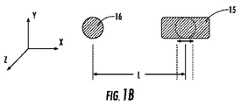
図1A、図2及び図3は、第1の光ファイバフェルール10(図1A)及び第2の光ファイバフェルール20(図2及び図3)の実施例を示す等角図である。第1及び第2の光ファイバフェルール10,20は、光ファイバインタフェース装置を構成するのに適した相補形構造体に用いられる相補嵌合幾何学的形状部を有し、このような光ファイバインタフェース装置は、例えば、光ファイバプラグ、アダプタ、相互接続部及び光ファイバインタフェース装置を含む。具体的に説明すると、図1Aは、第1の光ファイバインタフェース装置60の一部分である第1の光ファイバフェルール10(以下、フェルールという)の等角図である。図2及び図3は、第2のフェルール20の等角図である。図示のように、第1の端部12Fを備えた本体12を有し、この第1のフェルール10は、前側端部又は前端22F及び後側端部又は後端22Rを備えた本体を有する第2のフェルール20とインタフェースすると共にこれと光接続を行うための嵌合幾何学的形状部で構成されている。 1A, 2 and 3 are isometric views showing an embodiment of the first optical fiber ferrule 10 (FIG. 1A) and the second optical fiber ferrule 20 (FIGS. 2 and 3). The first and second
第1のフェルール本体12は、フェルール本体前側端部12Fのところに端部14Eを備えた複数本の光通路14を更に有している。本明細書において用いられる「光通路」という用語は、光信号の伝送を可能にするフェルールの任意適当な構造部材又はコンポーネントを意味している。一例を挙げると、光通路14は、光導波路、例えば光ファイバ、光学レンズ(レンズ素子)、能動素子、例えば垂直共振器表面発光ダイオードレーザ(VCSEL)、フォトダイオード、光検出器若しくは他の能動素子又は光信号を送信し又は受信するフェルールの他の構造部材又はコンポーネント若しくはフェルールに取り付けられていて、光信号を送信し又は受信する他の構造部材又はコンポーネントを受け入れてこれを収納支持する光ファイバボアを有するのが良い。 The
第1のフェルール10は、嵌合幾何学的形状部として、フェルールを互いに嵌合させたときに第2のフェルール20のガイドピン25を受け入れるスロット15を有している。この実施形態では、第1のフェルール10は、嵌合幾何学的形状部として、相補フェルールとの嵌合時にスロット15と協働する第2の雌型部分、例えば穴16を更に有している。換言すると、スロット15及び穴16は、各々、第2のフェルールのそれぞれのガイドピン25を受け入れる。スロット15及び穴16は、第2のフェルール20のガイドピン25と協働するように寸法決めされると共に間隔を置いて配置されている。 The
本明細書で用いられる「スロット」という用語は、嵌合幾何学的形状部がその相補嵌合幾何学的形状部に対して、嵌合幾何学的形状部の両方の中心線(即ち、X軸)を通り、それによりスロットとその対応の嵌合幾何学的形状部、例えばピンとの間の大きなアライメント公差の実現を可能にする方向において十分に大きめであることを意味している。1つ又は2つ以上のスロットを含む嵌合幾何学的形状部を備えたフェルールは、多数回の嵌合サイクルを許容する。というのは、このようなフェルールは、締まり嵌め関係を作るための厳しい公差のボアとガイドピンの嵌合幾何学的形状部を有する従来型フェルールの場合のように比較的多数回の嵌合サイクルが行われた場合に高いレベルのデブリを発生させることがないからである。 As used herein, the term “slot” refers to the centerline of both mating geometries (ie, X X) with respect to its complementary mating geometry. Means sufficiently large in a direction that allows a large alignment tolerance to be realized between the slot and its corresponding mating geometry, for example a pin. A ferrule with a mating geometry that includes one or more slots allows multiple mating cycles. This is because such ferrules have a relatively large number of mating cycles as in the case of conventional ferrules with tight tolerance bores and guide pin mating geometry to create an interference fit relationship. This is because no high-level debris is generated when this is performed.
さらに、スロット15は、嵌合フェルールの相補嵌合幾何学的形状部、例えばガイドピン相互間の大きな公差を許容する。換言すると、第2のフェルールの嵌合幾何学的形状部の公差は、大きなばらつきを有しても良い一方で、更に、適当なアライメント及び光学性能を提供することができる。 Further, the
図1Bは、第1のフェルール10と第2のフェルール20との間の嵌合幾何学的形状部の略図である。具体的に説明すると、第1のフェルール10の嵌合幾何学的形状部は、陰影を付けた領域で表され、第2のフェルール20の嵌合幾何学的形状部は、破線で示されている。嵌合幾何学的形状部が丸い形又は丸形端部を備えたスロットの形として概略的に示されているが、嵌合幾何学的形状部(即ち、スロット、穴及び/又はピン)について任意適当な形状、例えば正方形、長方形、六角形等を用いることができる。図示のように、第1のフェルール10と第2のフェルール20との間の嵌合幾何学的形状部の左側は、同一形状を用いた比較的ぴったりとした滑り嵌め状態を有し、それにより、アライメント基準データが作られる。他方、第1のフェルール10と第2のフェルール20との間の嵌合幾何学的形状部の右側は、同一形状を備えていない。換言すると、第1のフェルール10のスロット15は、第2のフェルール20の嵌合特徴部(例えば、ガイドピン25)よりも大径であり、図示のように左側嵌合幾何学的形状部と右側嵌合幾何学的形状部との間の中心距離L周りに公差を提供している。さらに、嵌合幾何学的形状部は、エッジのところに設けられていて、アライメントを助けると共に/或いは嵌合を繰り返しても摩耗及びデブリの発生を軽減する面取り部等を有するのが良い。 FIG. 1B is a schematic representation of the mating geometry between the
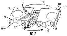
図2及び図3は、第1のフェルール10と嵌合するのに適した形態の第2のフェルール20の例示の実施形態を示している。第2のフェルール20は、光導波路、例えば光ファイバ40(図2及び図3には示されておらず、図9を参照されたい)を受け入れてこれらを支持する多数のボアの形態をした上述の複数本の光通路14を備えた本体22を有している。第2のフェルール20は、第1のフェルール10の嵌合幾何学的形状部によって受け入れられる寸法及び形状の少なくとも1本のガイドピン25を有する嵌合幾何学的形状部を含み、それにより2つの嵌合フェルールの光導波路を軸合わせしている。図示のように、ガイドピン25は、第2のフェルール20の本体22と一体に形成されている。換言すると、ガイドピン25は、フェルール20の本体22と同種の材料で作られると共にこれと一体である。 2 and 3 show an exemplary embodiment of the
図示の実施形態では、第2のフェルール20は、複数本の光通路14の互いに反対側で第2のフェルール20の本体に一体に形成された2本のガイドピン25を有している。フェルールのガイドピンボア内に受け入れられてピンリテーナにより定位置に保持される高精度機械加工ガイドピンを用いた従来型光ファイバフェルールとは異なり、第2のフェルール20のガイドピン25は、本体22中に成形され、機械加工され又は違ったやり方で一体形成される。さらに、フェルール20のガイドピン25は、第1のフェルール10の嵌合幾何学的形状部(例えば、スロット15及び穴16)に係合するのに十分な距離突き出ており、それにより互いに嵌合状態にあるフェルール10,20のそれぞれの光通路14(例えば、ボア)内に設けられた光導波路(例えば、光ファイバ40、図19参照)を互いに軸合わせしている。しかしながら、第1のフェルール10を1又は2本以上の従来型ガイドピンがフェルールのガイドピンボア内に受け入れられる従来型のフェルールを用いた相補形フェルールに嵌合させても良い。 In the illustrated embodiment, the
本明細書において開示する第1及び第2のフェルール10,20の嵌合幾何学的形状部は、多くの理由で従来型嵌合幾何学的形状部と比べて利点をもたらす。従来型嵌合幾何学的形状部は、従来型フェルールのガイドピンボア内に嵌まり込む専用のガイドピンを用い、典型的には、その結果として、ガイドピンボア間隔のばらつきに起因してガイドピンとガイドピンボアとの間に締まり嵌め状態が生じる。従来型フェルールに用いられるこの締まり嵌めにより、比較的多くの回数の嵌合サイクルを受けたとき、摩耗及びデブリが生じる。 The mating geometry of the first and
他方、少なくとも1つのスロット15を備えた第1のフェルール10を用いると、多数回の嵌合サイクルで生じる摩耗及びデブリの量が減少する。さらに、ガイドピン25を第2のフェルール20の本体22に一体に形成することにより、例えば消費者向け電子装置で見受けられる比較的多くの回数の嵌合サイクルに適した確実且つ低コストの手段が得られる。換言すると、嵌合幾何学的形状部は、これにより例えば消費者向け電子装置に特有の多くの回数の嵌合/離脱サイクルの利用が可能であるので有利である。さらに、少なくとも1つのスロット15を有する第1のフェルール10の嵌合幾何学的形状部は、従来型嵌合幾何学的形状部と比較して、フェルールの嵌合幾何学的形状部相互間の摩耗が減少する。 On the other hand, using the
第2のフェルール20は、オプションとして、他の特徴部を有するのが良い。図示のように、第2のフェルール20は、本体22の後側端部22Rに設けられた少なくとも1つの保持特徴部27を有する。具体的に説明すると、第2のフェルール20は、フェルールの後側端部22Rのところに設けられると共に複数本の光通路14の互いに反対側に設けられた少なくとも2つの保持特徴部27を有する。保持特徴部27は、それぞれ対応の弾性部材75(図示すると共に以下において説明し、これについては、例えば図9を参照されたい)、例えばばねを保持するよう構成されている。保持特徴部27は、突出部として示されているが、他の構造、例えば止まり穴、凹部、スナップ装着構造等が採用可能である。 The
さらに、第2のフェルール20は、オプションとして、1つ又は2つ以上の停止部28′(図2参照)を有するのが良い。具体的に説明すると、第2のフェルール20は、フェルール本体前側端部22Fから引っ込められると共に複数本の光通路14の互いに反対側に設けられた2つの停止部28を有するが、停止部は、フェルール本体前側本体22と面一であっても良く又はこれを越えて延びても良い。第2のフェルール20の他の領域も又、凹み領域を有して良い。一例を挙げると、第2のフェルール20は、オプションとしてガイドピン25の周りに凹み領域26を有し、これら両方のガイドピンは、図2に最も良く示されているように、フェルール本体22の内部に一体に形成されている。 Further, the
汚染からの悪影響を軽減する別の形式の凹部26が例えば図11に示されているトレンチの形態をしており、図26と関連してこれにつき以下に説明する。さらに、本明細書において開示するフェルールは、光接続に加えて更に電気接続を提供し、それによりハイブリッド接続を提供する。以下において、光接続と電気接続の両方をサポートする例示のフェルールについて説明する。本明細書で開示する光ファイバインタフェース装置は、光接続能力か光接続能力と電気接続能力の両方かのいずれかを有することができるので、説明を容易にするために、これら両方の形式の光ファイバインタフェース装置を本明細書において光ファイバインタフェース装置と称する。 Another type of
第1及び第2のフェルール10,20は、光通路14に隣接して位置する傾斜部分19を更に有するのが良い。傾斜部分19は、光通路14内に第1及び第2のフェルール10,20により支持された光ファイバ40のレーザ加工を許容し又は考慮に入れている。具体的に説明すると、傾斜部分19は、光通路14によって支持された光ファイバ40のレーザ加工中、フェルールの前側端部へのマーク付け及び/又は損傷を阻止する凹みを提供することにより製造を助ける。傾斜部分19は、レーザビームによる光ファイバ40の切断及び/又は研磨中、レーザビームLB及び/又はデブリ相互間の作用を阻止し、それによりフェルール10(図1A参照)の前側端部12Fに対するマーク付け及び/又は損傷を阻止するよう構成されている。 The first and
図1A及び図2に示されているように、傾斜部分19は、フェルール10,20の長手方向軸線に対して傾斜した表面を有するのが良い。傾斜部分19は、任意適当な角度及び/又は幾何学的形状、例えば前面から30°〜40°の角度をなすのが良いが、他の適当な角度/幾何学的形状が採用可能である。さらに、傾斜部分19は、フェルールの寸法及び構造健全性が保たれる限り、光通路14から任意適当な距離を置いたところで始まっても良い。 As shown in FIGS. 1A and 2, the
他の変形例では、傾斜部分19は又、オプションとして、光通路14を備えたフェルールの前面から後方に引っ込んで配置されても良い。一例を挙げると、傾斜面19に隣接して肩が形成されても良く、それにより傾斜面をフェルールの前面から後方に引っ込めることができる。例えば、肩は、フェルールの前面(例えば、フェルール本体前側端部22F)から約2ミクロン以上の深さを有するのが良い。 In other variations, the
フェルール10,20は、傾斜部分19を有しているので、フェルールにより支持された複数の光ファイバ40の加工では、1つ又は2つ以上のステップでレーザビームLBによる複数本の光ファイバの切断及び/又は研磨が行われる場合がある(図1A参照)。例えば、レーザビームLBで光ファイバ40を切断すると共に研磨するために別々のステップが用いられても良いが、切断及び研磨は、レーザビームを用いて一ステップで行われても良い。レーザビームLBを発生させる上で任意適当な形式のレーザ及び/又は動作モードを使用することができる。 Since the
一例を挙げると、レーザビームLBを発生させるレーザは、パルスモード、連続モード又は他の適当なモードで動作するCO2レーザであるのが良い。また、レーザビームLBと光ファイバ40とのなす角度を調節すると、光ファイバ40の端部に所望の角度、例えば10°、8°又は0°(平坦)の角度を設けることができる。ボアを有するフェルール本体前側端部12Fの部分と前側端部の外側部分との間の距離に起因して、レーザビームLBは、複数本の光ファイバ40の切断及び研磨中、フェルール10,20との相互作用を実質的に回避する。As an example, the laser that generates the laser beam LB may be a CO2 laser operating in pulsed mode, continuous mode, or other suitable mode. Further, by adjusting the angle formed by the laser beam LB and the
オプションとしての傾斜部分19は、レーザビームLBの屈折部分とデブリとフェルールとの相互作用の確立を一段と減少させるよう設けられている。例えば、レーザビームLBは、フェルール10,20の底部から傾斜部分19に向かう全体的方向において複数本の光ファイバ40を切断すると共に/或いは研磨するよう位置合わせされるのが良い。 An optional
一例を挙げると、第1及び第2のフェルール10,20を用いた適当な相補構造は、一例として、それぞれレセプタクル型光ファイバインタフェース装置(「レセプタクル」)60(図6参照)及びプラグ型光ファイバインタフェース装置(「プラグ」)70(図7参照)として構成された第1及び第2の光ファイバインタフェース装置を含み、これら光ファイバインタフェース装置により、ユーザは、これら相互間の迅速且つ確実な光及び/又はハイブリッド接続(即ち、光/電気接続)を行うことができる。具体的に説明すると、第1のフェルール10及び第2のフェルール20は、オプションとしてそれぞれの電気接点63,73(図6及び図7参照)を有するのが良く又は変形例として光USB光ファイバインタフェース装置の一部分を形成することができるそれぞれのUSB光ファイバインタフェース形の部分を形成している。換言すると、一例では、図示のようにプラグ70は、USBプラグ型光ファイバインタフェース装置として構成され、レセプタクル60は、USBレセプタクル型光ファイバインタフェース装置として構成されている。 For example, suitable complementary structures using the first and
図6〜図10に示されたレセプタクル60及びプラグ70と組み合わせて第1及び第2のフェルール10,20の他の細部について以下に説明する。第1及び第2のフェルールに関する技術的思想は、他形式のフェルール、光ファイバインタフェース装置及び嵌合装置に有用である。 Other details of the first and
例示のMTP互換性光ファイバインタフェース装置Exemplary MTP compatible fiber optic interface device
図4及び図5は、それぞれ、相補形PMT互換性嵌合幾何学的特徴部を備えた別の1組の例示の第1及び第2のフェルール110,120を用いたそれぞれの例示としての光ファイバインタフェース装置100,101の側面等角図及び分解組立て図である。第1のフェルール110は、嵌合幾何学的形状部の一部としてフェルール10に類似した本体112に形成されている少なくとも1つのスロット115を備えた嵌合幾何学的形状部を有する。同様に、第2のフェルール120は、嵌合幾何学的形状部の一部としてフェルール20に類似した本体と一体に形成されている少なくとも1本のガイドピン125を備えた嵌合幾何学的形状部を有する。互いに嵌合した第1及び第2のフェルール110,120は、アダプタ(図示せず)を用いて互いに嵌合するMPO型光ファイバインタフェース装置、例えばMT光ファイバインタフェース装置として構成されているが、開示した技術的思想を用いた他の光ファイバインタフェース装置構成例の実現が可能である。さらに、光ファイバインタフェース装置100,101は、フェルールのボア中に挿入される1又は2本以上の光導波路、例えば光ファイバ40(分かりやすくするために図示されていない)を有するケーブル組立体の一部である。光ファイバインタフェース装置100,101は、開示した技術的思想に従ってフェルールを有する場合のある光ファイバインタフェース装置及びケーブル組立体の例そのものである。 FIGS. 4 and 5, respectively, illustrate respective exemplary light using another set of exemplary first and
具体的に説明すると、図4は、組み立て状態の光ファイバインタフェース装置100の等角図であり、図5は、これに類似した光ファイバインタフェース装置101の分解組立て図である。光ファイバインタフェース装置100,101の同一の部品は、同一の番号で示されている。光ファイバインタフェース装置100は、オプションとして、ばね受座104、コイルばね105、ばねプッシュ118、引き込み管130及び全体として中空の光ファイバインタフェース装置ハウジング102を有するのが良い。図4に示された例示の実施形態のオプションとしてのばね受座104は、フェルール110及びコイルばね105に隣接したフェルール110の後側端部の後面に隣接して位置決めされるのが良い。ばね受座104を長さ方向に貫通して延びる開口部106が引き込み管130及び光導波路(図示せず)の端部分をばねプッシュ118に通してフェルール110の後面まで至らせることができるよう構成されるのが良い。引き込み管130は、ばねプッシュ118の開口部122、コイルばね110の開口部112及びばね受座104の開口部106内に位置決めされるのが良い。引き込み管130を長さ方向に貫通して延びる開口部132がそれぞれのフェルールのそれぞれのボア内に光ファイバケーブルの光ファイバの端部分を受け入れてこれらを案内する。 Specifically, FIG. 4 is an isometric view of the optical
光ファイバインタフェース装置100は、この光ファイバインタフェース装置をアダプタ(参照符号が付けられていない)内に嵌合させると共に固定するアライメント及び/又は取り付け構造体を有するのが良い。図示のように、フェルール110、ばね受座104、コイルばね105、ばねプッシュ118の前方部分124及び引き込み管130は、少なくとも部分的に光ファイバインタフェース装置ハウジング102内に位置決めされるのが良い。一例では、可撓性ラッチ、例えば、ばねプッシュ118に設けられたアーム126の形態をした突出部付きのラッチが前方部分124から長さ方向に延びて、ばねプッシュ118を光ファイバインタフェース装置ハウジング102内に固定するために光ファイバインタフェース装置ハウジング102内に形成された開口部103に係合するのが良い。前方機械的停止部(見えない)を光ファイバインタフェース装置ハウジング102の内面に設けてフェルール110が光ファイバインタフェース装置ハウジング102内に設けられたときに動くことができるが、この中に保持されるようにするのが良い。フェルール110は、コイルばね105及びばね受座104によって前方方向に付勢されている。 The fiber
図5の光ファイバインタフェース装置101は、光ファイバインタフェース装置100とほぼ同じ構成のものであるが、フェルール110に代えてフェルール120を有しており、それにより、光ファイバインタフェース装置100と嵌合するのに適したケーブル組立体が提供されている。 The optical
USB互換性光ファイバインタフェース装置の第1の実施例First Embodiment of USB Compatible Optical Fiber Interface Device
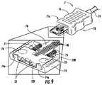
図6〜図10は、図1Aに示されている第1のフェルール10及び図2及び図3に示されている第2のフェルール20をそれぞれ用いたUSB互換性光ファイバインタフェース装置の第1の実施例をそれぞれ示す側面等角図である。具体的に説明すると、図6及び図10は、レセプタクル60を示し、図7〜図9は、プラグ70を示している。レセプタクル60は、ケーブル69に取り付けられ、それによりレセプタクルケーブル組立体6が形成され、他方、プラグ70は、ケーブル79に連結され、それによりプラグケーブル組立体7が形成されている。レセプタクル60とプラグ70は、相対的な1つの向きをなして互いに直接嵌合し、これらは、互いに押し付けられることにより、これらの間に光接続部又は光及び電気接続部を形成している。フェルール10,20は、レセプタクル60及びプラグ70の一部分として示されているが、フェルール又はこのようなフェルールの変形例を他形式の光ファイバインタフェース装置、例えば光のみの光ファイバインタフェース装置に用いても良い。 6 to 10 show a first example of a USB compatible optical fiber interface device using the
レセプタクル60は、エンクロージャ61eの内部62i内に少なくとも部分的設けられた第1のフェルール10を有し、このエンクロージャ61eは、一例では、図6及び図10に示されているようにシュラウド62の形態をしている。一例では、シュラウド62は、実質的に長方形断面を有する円筒形金属シェルである。レセプタクル60は、USB光ファイバインタフェース装置として構成されている。具体的に説明すると、レセプタクル60は、この例では、電気接続部のみを有するUSBプラグと下位(後方)互換性があり、このようなレセプタクルを光接続部又は光接続部と電気接続部の両方を有する適当なUSBプラグに用いることができる。 The
具体的に説明すると、レセプタクル60は、プラグ70の電気接点73との電気的接続部を作る複数個の電気接点63を更に有している。電気接点63は、フェルール10と一緒に成形されるのが良く、その結果、これら電気接点63は、フェルールの拭い取り表面(即ち、電気接点を含むフェルールの水平面)から僅かに突出し又はこれと比較的面一をなし、或いは、他の適当な取り付け手段を有する。レセプタクル60は、電気接点63との電気接続部を作る光ファイバインタフェース装置の後部まで引き回され又はフェルール10の複数本の光通路14まで引き回された伝送要素69(例えば、電線と光ファイバの両方)を有する。一例では、伝送要素69は、ひとまとまりとなって、ケーブルを構成し、したがって、これら伝送要素を以下、ケーブル69ともいう。 Specifically, the
シュラウド62は、レセプタクル60を回路板等に固定すると共に/或いはアースするタブ65を更に有する。図10に最も良く示されているように、シュラウド62は、プラグとレセプタクル60を互いに嵌合させたときにプラグをレセプタクル60に固定する複数本のラッチ止めアーム62aを有している。図面では見えないが、第2の組をなすラッチ止めアーム62aがシュラウド62の下面に設けられる。図示のように、ラッチ止めアーム62aは、片持ちされているが、他の適当な構成を有しても良く又はこれらを全て省いても良い。さらに、図10に示されているように、例示としてのシュラウド62が2つの半部から形成され、ロックタブ62bが2つの半部をシーム62sのところで固定するために用いられている。 The
図7〜図9は、レセプタクル60との嵌合に適した例示のプラグ70の前側端部側面立面図である。プラグ70は、ハウジング71及びハウジングの一端に作動的に連結されたシュラウド72を含むエンクロージャ71eを有する。エンクロージャ71eは、内部72iを画定している。プラグ70は、シュラウド72によって構成された内部72iの部分内に少なくとも部分的に設けられている上述の第2のフェルール20を更に有している。シュラウド72は、レセプタクルシュラウド62とほぼ同じであるが、この中に嵌まり込んでいる。図8は、プラグフェルールガイド74内に設けられたフェルール20を示す拡大図を含み、図9は、フェルールガイド74内で協働するフェルール20を示すためにシュラウド72が取り除かれた状態のプラグ70を示している。 FIGS. 7-9 are front end side elevational views of an
例示のプラグ70は、フェルール20、ハウジング71及びシュラウド72を有するエンクロージャ71e、電気接点73、フェルールガイド74、フェルール20を前方に付勢する一対の弾性部材75を有している。レセプタクル60と同様に、例示のプラグ70は、USB光ファイバインタフェース装置として構成されているが、本明細書において開示する技術的思想の範囲内で他形式の光ファイバインタフェース装置が採用可能である。具体的に説明すると、例示のプラグ70は、電気接続部のみを有するUSBプラグと下位(後方)互換性があり、このようなプラグを光接続部又は光接続部と電気接続部の両方を有する適当なUSBプラグに用いることができる。具体的に説明すると、プラグ70は、レセプタクル60とプラグ70との電気接続部(即ち、レセプタクル60の対応の電気接点63との電気接続部)を作るための上述の複数個の電気接点73を有する。 The illustrated
レセプタクル60の場合と同様、電気接点73は、フェルールと一緒に成形されるのが良く、その結果、これら電気接点73は、フェルールの拭い取り表面(即ち、電気接点を含むフェルールの水平面)と比較的面一をなし、或いは、他の適当な取り付け手段を有する。プラグ70は、電気接点73との電気接続部を作る光ファイバインタフェース装置の後部まで引き回され又は図示のようにフェルール20の複数本の光通路14まで引き回された伝送要素79(例えば、電線と光導波路の両方)を有する。一例では、伝送要素79は、ひとまとまりとなって、ケーブルを構成しており、したがって、これら伝送要素を以下、ケーブル79ともいう。 As with the
図9の拡大図は、プラグフェルールガイド74の開口部72内に設けられると共に1つ又は2つ以上の弾性部材75によって前方位置に付勢されたフェルール20を示している。図示のように、フェルールガイド74は、チャネル78を有し、このチャネルは、ケーブル79の光導波路(即ち、伝送要素)をフェルール20に引き回す通路を提供するようフェルール本体後側端部22Rに通じる開口部76に連結されている。この実施形態では、弾性部材75は、コイルばねであるが、他の適当な弾性部材、例えば板ばね等が採用可能である。 The enlarged view of FIG. 9 shows the
図2に最も良く示されているように、フェルール20は、複数本の光通路14の互いに反対側に設けられた保持特徴部27を有する。図示のように、保持特徴部27は、弾性部材75をフェルール本体後側端部22Rに着座させる突出部である。さらに、プラグフェルールガイド74は、弾性部材75の第2の端部を着座させる突出部等(図示せず)を有している。プラグフェルールガイド74は、フェルール20の移動をフェルールガイド開口部76内に制限するフェルール停止部74aを更に有している。フェルール停止部74aは、フェルール20に設けられた停止部28′(図2参照)と相補する形状及び位置を有する。さらに、フェルール停止部74a及び停止部28は、フェルール20をプラグフェルールガイド74の開口部76に対して心出しすると共に過度の側方変位を阻止するのを助ける相補した傾斜面を有する。 As best shown in FIG. 2, the
シュラウド72を取り付けると、フェルール20は、図7及び図8に示されているように、プラグフェルールガイド74とシュラウド72との間に捕捉される。シュラウド72は、嵌合時にプラグ72をレセプタクル60に固定するためにレセプタクル60のラッチ止めアーム62aと協働する複数個の窓72aを更に有している。さらに、プラグフェルールガイド74の反対側は、電気接点73を図示のようにこのプラグフェルールガイドに取り付けるために用いられている。 When the
さらに、第1のフェルール10は、本明細書において開示したスロット構成を依然として用いた状態で他の嵌合幾何学的形状部を有しても良い。一例を挙げると、図11は、上述したフェルールと類似しているが、光通路14の互いに反対側に設けられたスロット15及びガイドピン25を備えた嵌合幾何学的形状部を有するフェルール10を含むフェルール10を有する例示のレセプタクル60を示している。換言すると、図11の例示のフェルール10は、2つの雌型部分ではなく、1つの雌型部分及び1つの雄型部分を有している。雌型スロット部分及び雄型ピンを同一のフェルールに用いるという技術的思想を任意他のフェルール及び/又は光ファイバインタフェース設計に用いることができる。図11は又、光通路端部14Eのところに位置した光ファイバ端部40Eを示している。 Further, the
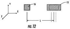
さらに、上述したように、嵌合幾何学的形状部は、丸形以外の形状を有しても良い。一例を挙げると、図12は、第1のフェルールに関してスロット15及び長方形の穴16を備えた非丸形相補嵌合幾何学的形状部を示す略図である。第2のフェルール20は、スロット15及び穴16と嵌合する寸法及び形状の長方形のガイドピンとして構成された相補嵌合幾何学的形状部を有している。平坦な表面を有する嵌合幾何学的形状部を用いることにより、2つの対向したフェルールの嵌合幾何学的形状部相互間の力を減少させることができる。換言すると、この力は、丸形幾何学的形状部により作られる線接触と比較して、平坦な表面(即ち、正方形及び長方形)を備えた広い表面上に分散される。平坦な表面を用いることにより、摩耗及びデブリの生成を減少させることができる。更に、平坦な表面を用いることにより、フェルール相互間の脆弱な軸線に沿う安定性を増大させることができる。換言すると、連結安定性を向上させることができ、その理由は、脆弱な軸線に沿うフェルール相互間に角度(即ち、ピンの中心線周りに曲げ)をもたらす前に平坦な表面について、より多くの材料を変形させなければならないからである。 Furthermore, as described above, the fitting geometric shape portion may have a shape other than a round shape. To give an example, FIG. 12 is a schematic showing a non-round complementary mating geometry with a
USB互換性光ファイバインタフェース装置の実施例Example of USB compatible optical fiber interface device
上述したように、汚れ、ダスト及び他のデブリの形態の汚染要因物に定期的に遭遇する多くの環境で作動される場合が多い電子装置、例えば消費者向け電子装置に用いられるのに適した光ファイバインタフェース装置の要望が高まっている。このような汚染要因物は、光ファイバインタフェース装置が電子装置と光学的又は光学的且つ電気的に通信する能力に悪影響を及ぼす場合がある。汚染要因物の悪影響に強くしかも実質的に汚染要因物のない接続部を維持するよう容易にクリーニングできる光ファイバインタフェース装置を提供することが有利である。 As mentioned above, suitable for use in electronic devices that are often operated in many environments that regularly encounter contaminants in the form of dirt, dust and other debris, such as consumer electronic devices There is an increasing demand for optical fiber interface devices. Such contaminants can adversely affect the ability of the fiber optic interface device to communicate optically or optically and electrically with electronic devices. It would be advantageous to provide an optical fiber interface device that is resistant to the adverse effects of contaminants and that can be easily cleaned to maintain a connection that is substantially free of contaminants.
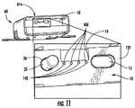
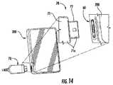
図13は、レセプタクル60のところで例示のプラグ型光ファイバインタフェース装置70が作動的に連結された例示の手持ち型電子装置200の平面図側の等角図である。図14は、図13に類似しており、電子装置200から切り離されたプラグ型光ファイバインタフェース装置(プラグ)70を示している。電子装置200は、図14の挿入図に最も良く示されているように消費者向け電子装置内に位置した例示のレセプタクル型光ファイバインタフェース装置(光ファイバインタフェース装置)60を有している。 FIG. 13 is an isometric view of the exemplary handheld
図15及び図16は、それぞれ、プラグ70及びレセプタクル60の正面図である。プラグ70は、ハウジング71及びシュラウド72を備えた上述のエンクロージャ71eを有している。プラグフェルール20は、プラグフェルールガイド74によって可動的に支持されている。電気接点73がプラグフェルールガイド74の2本のアーム74Aの各々のそれぞれの外方側部74Sに設けられている。一例では、光通路14内には、勾配屈折率(GRIN)レンズ要素210が設けられ、これらGRINレンズは、フェルール本体前側端部22Fのところで支持されている。 15 and 16 are front views of the
レセプタクル型光ファイバインタフェース装置60は、フェルール10を有し、フェルール10のフェルール本体12は、アーム12A、中央本体部分12C及びフェルールガイドアーム74Aを受け入れるよう構成された停止部28′を有している。アーム12A及び中央フェルール本体部分12Cは、スロット13を画定し、アームは各々、電気接点63が設けられた内方側部29Sを有している。レセプタクル型及びプラグ型光ファイバインタフェース装置60,70は、互いに嵌合してプラグ及びレセプタクル光通路14が位置合わせされると共にGRINレンズ要素210を介して光通信関係をなし、しかも、レセプタクル及び電気接点63,73が互いに電気的接触関係をなすよう構成されている。レセプタクル型光ファイバインタフェース装置60は、シュラウド62の形態をしたエンクロージャ61eを有している。一例では、エンクロージャ61eは、レセプタクルフェルール10とプラグフェルール20を位置合わせすると共に相互のぶつかりを回避するよう構成されている。他の嵌合幾何学的形状部、例えば、さねはぎ方式を利用することができ、その結果、レセプタクルフェルール10とプラグフェルール20が前側端部12F,22Fを位置合わせするようになっている。 The receptacle-type optical
図15及び図16に示されている実施形態では、レセプタクルフェルール前側端部12F及びプラグフェルール前側端部22Fは、本質的に平面状であり、即ち、これらは、光通路14の端部14Eを除き、ピン、穴又はスロットを備えていない。これにより、これらフェルール前側端部から非引っ込み位置のままで汚染要因物を容易に除去することができる。 In the embodiment shown in FIGS. 15 and 16, the receptacle ferrule
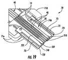
図17は、嵌合中におけるレセプタクル型及びプラグ型光ファイバインタフェース装置60,70の切除側面等角図であり、説明を容易にするためにレセプタクル60のレセプタクルフェルール10だけが示されている。図18は、図17のレセプタクル及びプラグフェルール10,20の拡大図であるが、レセプタクル型光ファイバインタフェース装置60とプラグ型光ファイバインタフェース装置70は、嵌合状態にある。プラグフェルール20内の光通路14のうちの1本だけが一例として図18に想像線で示されている。図19及び図20は、それぞれ、非引っ込み状態及び引っ込み状態におけるプラグ70のプラグフェルールガイド74及びプラグフェルール20の拡大切除側面等角図である。プラグフェルール20は、前側端部22F、後側端部22R及び前側フェルール端部と後側フェルール端部との間に位置したリップ22Lを有している。 FIG. 17 is a cut-away side isometric view of the receptacle-type and plug-type optical
図17及び図18を参照すると、プラグ70は、シュラウド72及びハウジング71の頂部が取り外された状態で示されており、後には、前側端部71F及び後側端部71Rを有するハウジング底部71Bだけが残されている。ハウジング底部71Bは、少なくとも1つの保持特徴部27を有している。プラグフェルールガイド74がハウジング底部内に形成された切除部分(ニッチ)71N内でハウジング底部71Bの前側端部71Fのところに設けられている。プラグフェルールガイド74は、プラグフェルール20の中央部分22Cに摺動可能に係合するよう寸法決めされた中央開口部(スロット)76を有している。プラグフェルールガイド74は、中央スロット76の各側に設けられていて、それぞれのプラグ電極73を支持した側部スロット77を有している。 Referring to FIGS. 17 and 18, the
少なくとも1つの弾性部材75が少なくとも1つの保持特徴部27とプラグフェルール後側端部22Rとの間に作動的に位置すると共にハウジング底部71Bに載っている。4本の光ファイバ40がハウジング後側端部71Rのところで後側光ファイバガイド80を貫通して光通路14まで延びている状態で示されている。光ファイバ40は、コイル状又は別の形状のたるみ区分40Cを有し、たるみ区分40Cは、ハウジング底部71Bに設けられた収納領域(空間)71S内に且つハウジング後側端部71Rに隣接して位置した余剰光ファイバ部分を有している。一例では、収納領域(空間)71Sは、レセプタクルハウジング底部71Bを従来サイズのUSBレセプタクル型光ファイバインタフェース装置に対して伸長させることにより形成されている。 At least one
一例では、プラグフェルール20は、フレア状後側端部22Rを有している。この特徴部により、弾性部材75をプラグフェール中心軸線A20の外側に配置することができ、その結果、光通路14をプラグフェルール中心軸線上に又はこの周りに配置することができるようになっている。この特徴部は又、光ファイバ40のための隙間を提供する。 In one example, the
図17は、互いに嵌合する直前におけるレセプタクル型光ファイバインタフェース装置60とプラグ型光ファイバインタレース装置70を示しており、弾性部材75は、実質的に弛緩し(例えば、圧縮度が最も僅かな状態にある)、プラグフェルール前側端部22Fは、ガイドアーム74Aの前側端部74Fと実質的に同一平面内に位置すると共にレセプタクルフェルール前側端部22Fに接触している。プラグフェルールリップ22Lは、プラグフェルール前側端部22Fがプラグフェルールガイドアーム74Aの前側端部74Fを越えて延びるのを阻止するためにプラグフェルールガイド後側端部74Rに当接するよう構成されている。図17は、前方付勢位置にあるプラグフェルール20を示している。 FIG. 17 shows the receptacle-type optical
図18は、嵌合状態にあるレセプタクル型光ファイバインタフェース60とプラグ型光ファイバインタフェース装置70を示しており、弾性部材75は、プラグフェルール20に押し付けられているレセプタクルフェルール10の力に起因して実質的に圧縮されており、プラグフェルール20は、プラグハウジング後側端部71Rに向かってプラグフェルールガイド中央スロット76内を摺動する。光ファイバ40は、コイル状になっており又は幾分かのたるみを有するよう構成されているので、光ファイバ40は、プラグフェルール20の前後の運動に順応することが必要な場合には単に動く。図18は、プラグフェルール20をその後方付勢位置で示しており、弾性部材75は、圧縮されている。 FIG. 18 shows the receptacle-type
図19及び図20は、それぞれ非引っ込み状態及び引っ込み状態におけるプラグ型光ファイバインタフェース装置70のプラグフェルールガイド74及びプラグフェルール20の拡大切除等角斜視図である。嵌合状態では、プラグフェルールガイド74のアーム74Aは、レセプタクルフェルール10の対応のスロット13内に嵌まり込み、プラグフェルールガイドアーム端部74Fは、レセプタクルフェルール10に設けられたそれぞれ対応関係にある停止部28′に当接する。プラグフェルール20は、プラグフェルールガイド74のアーム74Aの前側端部74Fに対して(即ち、プラグシュラウド前側端部72Fから)距離Dだけ軸方向に並進する。プラグフェルール20が後方付勢位置にあるとき、距離Dに関し、0.5mm≦D≦20mm又は好ましくは4≦D≦8mm、より好ましくは5mm≦D≦7mmである。 FIGS. 19 and 20 are enlarged cut-away isometric perspective views of the
一般に、距離Dは、エンクロージャ71eの前端72Fから測定されることに注目されたい。幾つかの場合、エンクロージャ前端72Fは、プラグシュラウド前端に一致する。他の場合、Dは、図22に示すと共に以下に説明するように、ハウジング前端61Fから測定された距離である。距離Dは、特定のフェルール(例えば、フェルール10かフェルール20かのいずれか)の前端から問題のフェルールが収納された特定の構造体の最も前側の端までの距離であり、エンクロージャという用語は、この最も一般的な意味において距離Dと関連して用いられている。 Note that in general, the distance D is measured from the
プラグフェルール20の並進構成により、プラグ型光ファイバインタフェース装置及びレセプタクル型光ファイバインタフェース装置によって支持されたそれぞれの光導波路40相互間の光接続をプラグシュラウド72内で確立することができる。この構成は、プラグとフェルールとの間の光インタフェース部を覆うことによって汚染の悪影響を軽減するのに役立ち、しかも角度抑制を向上させる。さらに、接続部が存在しない場合、プラグフェルール前側端部22Fは、プラグシュラウド前側端部72Fのところに又はそのすぐ近くに位置し、クリーニングのためにプラグフェルール前側端部に容易に接近できる(例えばマイクロデニール掃除用布を用いてプラグフェルール前側端部をきれいに拭き取ることができる)。これは、更に、光接続(又は、場合によっては光及び電気接続)に対する汚染要因物の悪影響を減少させるのに役立つ。 Due to the translational configuration of the
図21は、嵌合状態のレセプタクル型光ファイバインタフェース装置60とプラグ型光ファイバインタフェース装置70の幾つかの部分の拡大切除図である。レセプタクルフェルール10及びプラグフェルール20は、それぞれ、これらの光通路14内に且つこれらのフェルール前側端部12F,22Fに隣接してGRINレンズ要素210をそれぞれ支持している。GRINレンズ要素210は、それぞれの前面212及び後面213を有する。光ファイバ40は、それぞれの光ファイバ端部40EがGRINレンズ要素210の後面213とインタフェースするよう光通路14内に配置されている。一例では、GRINレンズ要素210の後面213は、光ファイバ端部40Eが平面状であるように平坦である。 FIG. 21 is an enlarged cutaway view of several parts of the receptacle-type optical
GRINレンズレンズ要素前面212は、1本の光ファイバインタフェース装置を別の光ファイバインタフェース装置に嵌合させたときに別の表面に接触しないことが望ましい場合がある。一例では、GRINレンズ要素210は、これらの前面214がこれらのそれぞれのフェルール前側端部12F,22Fから僅かに引っ込められるよう僅かに(例えば、数十ミクロン)引っ込められるよう配置されている。これにより、GRINレンズが互いに向かい合っているときにフェルール前面12F,22Fが互いに接触状態にある場合、GRINレンズ要素210の前面212相互間に僅かな隙間214が生じ、それにより、レンズ表面接触が回避される。一例では、隙間214は、25ミクロン〜100ミクロンの軸方向寸法を有する。GRINレンズ要素のこの離隔配置形態によりレセプタクル型光ファイバインタフェース装置60とプラグ型光ファイバインタフェース装置70を嵌合させたときにGRINレンズ要素前面212を損傷させる恐れが減少する。 別の例では、GRINレンズ要素210の前面212は、これらのそれぞれの前面212がこれらのそれぞれのプラグフェルール前側端部12F及びレセプタクルフェルール前側端部22Fに位置するよう配置される。GRINレンズ要素前面212が互いに接触するのを回避するため、一例では、嵌合状態にあるレセプタクル型光ファイバインタフェース装置60及びプラグ型光ファイバインタフェース装置70のうちの少なくとも一方は、突出特徴部(図示せず)を有するのが良い。 It may be desirable for the GRIN lens lens element
変形例では、光通路端部14Eを有するプラグフェルール前側端部12Fの部分は、フェルール前側端部の残部から僅かに引っ込められるのが良く、その結果、GRINレンズ要素210の前面212は、プラグフェルール前面12Fとレセプタクルフェルール前面22Fが互いに接触状態にあるとき、光通路端部のところに位置するが、レセプタクルフェルール20の対向したGRINレンズ要素前面212から依然として僅かに間隔を置いて位置したままであることができるようになっている。この引っ込みは又、レセプタクルフェルール20の前側端部22Fに設けられても良く、或いは、プラグ及びレセプタクルフェルール10,20の各々は、この引っ込み形態を有しても良い。 In a variation, the portion of the
USB互換性光ファイバインタフェース装置の別の実施例Another embodiment of a USB compatible optical fiber interface device
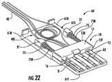
図22は、図17に類似した図であり、この場合、レセプタクル60が並進可能なレセプタクルフェルールを備えたUSB互換性光ファイバインタフェース装置の別の例示の実施形態を示している。この実施例におけるレセプタクル60の構成は、図13〜図20と関連して上述したプラグ70の構成に似ている。 FIG. 22 is a view similar to FIG. 17 showing another exemplary embodiment of a USB compatible fiber optic interface device with a receptacle ferrule into which the
レセプタクル60は、そのレセプタクルフェルール10が引っ込み(後方付勢)位置にある状態で図22に示されている。レセプタクルフェルール前側端部12Fがプラグ70と関連して上述したハウジング前側端部とほぼ同じハウジング前側端部61Fから上述の関連の距離D離れて位置していることに注目されたい。側面図である図23は、プラグ70に係合したレセプタクルを示している。レセプタクル60は、ハウジング前側端部61Fに隣接してレセプタクルハウジング底部61Bによって支持された多数の電気接点63を有している。プラグ70及びレセプタクル60は、ピン位置合わせ式USB光ファイバインタフェース装置組立体構成の一例である。ハウジング底部61Bは、光ファイバ40の余剰長さをコイル状又はたるみ形態で収納することができる上述の収納領域(空間)61Sを更に有している。 The
レセプタクル60とプラグ70を嵌合させると、レセプタクルフェルール前側端部12Fは、プラグフェルール前側端部22Fに接触する。レセプタクルフェルール10は、並進可能であるように構成されているので、レセプタクルフェルールは、レセプタクルとプラグを結合したときにレセプタクルフェルールに加わるプラグフェルールの軸方向力によって引っ込み位置に押し戻される。レセプタクルシュラウド62及びプラグシュラウド72は、説明を容易にするために図22及び図23から省かれていることに注目されたい。作動にあたり、レセプタクルシュラウド62は、プラグフェルールのガイド及び収納を助けるレセプタクルフェルールガイドとして働く。 When the
図24A〜図24Cは、レセプタクル60及びプラグ70の平面図側の等角図であり、レセプタクル‐プラグ嵌合作業の種々の段階を示している。図24Aでは、レセプタクル60とプラグ70を嵌合作業に先立って共通軸線A1に沿って互いに対向して配置する。この相対的位置では、レセプタクルフェルール10は、非引っ込み(前方付勢)位置にあり、レセプタクルシュラウド62の前側端部62Fに隣接して位置している。この位置により、必要ならばレセプタクルフェルール本体前側端部12Fのクリーニングが可能である。このようなクリーニングにより、例えば、特定のレセプタクル型態に応じて、光ファイバ40の端部40E又はGRINレンズ要素210の端面212から汚染要因物が除去される。 24A-24C are isometric views of the
図24Bでは、プラグシュラウド72をレセプタクルシュラウド62中に挿入する。レセプタクル60とプラグ70を軸線A1に押し付け、そしてプラグシュラウド72がレセプタクルシュラウド62内で摺動すると、プラグフェルール20は、レセプタクルフェルール10を押し、それにより、レセプタクルフェルール10は、弾性部材75が圧縮されるとシュラウド後側端部62Rの方向に軸方向に摺動する。図24Cは、レセプタクルフェルール10がその完全引っ込み(即ち、後方付勢)位置にあり、プラグシュラウド72がレセプタクルシュラウド62によって実質的に完全に包囲された最終の嵌合位置を示している。 In FIG. 24B, plug
一例では、弾性部材75(例えば、図22を参照されたい)は、自然に潰れるよう構成されており(例えば、切頭円錐形ばねとして)、それにより、フェルール20についてより長い移動距離を見込むことができる。また、一例では、弾性部材75は、それぞれのガイドロッド75Rの周りに配置され、ガイドロッド75Rは、弾性部材75が縮んだり弛緩したりしているときに弾性部材75をガイドするのに役立つ。ガイドロッド75Rは、保持特徴部27を貫通して延び、フェルール20の並進中、この保持特徴部を通って動くよう構成されているのが良い。 In one example, the elastic member 75 (eg, see FIG. 22) is configured to collapse naturally (eg, as a frustoconical spring), thereby allowing for a longer travel distance for the
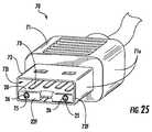
図25は、ガイドピン25に関する例示の形態を示す例示のプラグ70の正面等角図である。図26は、ガイドピン25の一例を示すプラグフェルール20の部分断面拡大図である。例示の構成のガイドピンは、ガイドピン25の基部を包囲したトレンチの形態をしている凹部26を有する。凹部26は、汚染要因物230、例えばデブリ、ダスト、汚れ、粒子、流体等を集めるよう構成されており、このような汚染要因物をプラグフェルール前側端部22F上に載せてプラグ及びレセプタクル連結を邪魔させるようにはなっていない。凹部26は、レセプタクル60とプラグ70を嵌合させることにより形成される光接続部(又は、光及び電気接続部)に対する汚染要因物の悪影響を軽減するのに役立つ。 FIG. 25 is a front isometric view of an
引っ込み可能なアライメント構造体Retractable alignment structure
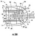
図27A及び図27Bは、引っ込み可能なアライメント構造体を有する例示のプラグ70の前端部側面等角図である。引っ込み可能なアライメント構造体は、突出部、ピン、アーム又はコンポーネントの位置合わせを行う他の適当なアライメント構造体であるのが良い。一例として、ガイドピン25が用いられる。図28A及び図28Bは、引っ込み可能なガイドピンを有する例示のプラグ70の平面図であり、2つの別々の形態のガイドピンを示している。 27A and 27B are front end side isometric views of an
引っ込み可能なガイドピン25は、ガイドピンスイッチ250に機械的に又は違ったやり方で協働的に連結されており、ガイドピンスイッチ250は、ガイド内ピンが引っ込み位置(図27A)又は非引っ込み(伸長)位置(図27B)に位置することができるようにする。図28A及び図28Bは、引っ込み可能なガイドピン25がガイドピンスイッチ250にそれぞれのビーム260により機械的に連結されている状態を示している。一例では、引っ込み可能なガイドピン25は、光ファイバケーブル79によって支持されたそれぞれの電線275に電気的に接続されており、送電を行うことができる電気接点としての役目を果たすことができる。 The
一例では、ピンスイッチ250は、プラグハウジング71の頂部に配置され、このピンスイッチは、ガイドピン25の並進時にプラグハウジングに沿って摺動する。一例では、スイッチ250は、ユーザの指がこれに容易に係合することができるよう構成されている。引っ込み可能なガイドピン25は、プラグフェルール20(図28A)内に設けられたガイドチャネル266内に支持されても良く、或いは、例えばフェルールガイド74(図28B)内に設けられたガイドピンチャネル266によってプラグフェルールに隣接して支持されても良い。 In one example, the
ユーザがプラグ70をクリーニングしたいと思ったとき、ユーザは、スイッチ250を操作してピン25を引っ込め、それによりフェルール前側端部22F及び光導波路端部40Eによって表された光インタフェース部への開放状態の(妨げられない状態の)接近を可能にする。図27Bの非引っ込み位置では、ピン25は、フェルール前側端部22Fへの接近を可能にするが、図27Aの引っ込みピン位置と関連した開放接近を可能にしない。図28A及び図28Bに示されている実施例では、フェルール前側端部22Fは、光ファイバ端部40Eが位置する凹み前側端部部分22F′を有する。他の実施例は、フェルール前側端部22Fのところに直接位置する光ファイバ端部を有するのが良い。いずれの場合においても、光ファイバ端部40Eへの接近は、ガイドピン25を引っ込み可能にすることにより容易になる。 When the user wants to clean the
本発明を好ましい実施形態及びその特定の実施例と関連して図示すると共に本明細書において説明したが、他の実施形態及び他の実施例が実質的に同一の機能を実行すると共に/或いは同一の結果を達成することができるということは、当業者には容易に明らかであろう。このような均等例としての実施形態及び実施例は全て、本発明の精神及び範囲に含まれ、特許請求の範囲に記載された本発明の範囲により包含されるようになっている。また、本発明の精神及び範囲から逸脱することなく、本発明の種々の改造例及び変形例を想到できることは当業者には明らかであろう。本発明は、本発明の改造例及び変形例が特許請求の範囲に記載された本発明の範囲及びその均等範囲に含まれることを条件としてこのような改造例及び変形例を含むものである。 Although the present invention has been illustrated and described herein in connection with a preferred embodiment and specific examples thereof, other embodiments and other examples perform substantially the same function and / or are identical. It will be readily apparent to those skilled in the art that the following results can be achieved. All such equivalent embodiments and examples are within the spirit and scope of the present invention and are intended to be covered by the scope of the present invention as set forth in the appended claims. It will be apparent to those skilled in the art that various modifications and variations can be made in the present invention without departing from the spirit and scope of the invention. The present invention includes such modifications and variations as long as the modifications and variations of the present invention are included in the scope of the present invention described in the claims and equivalents thereof.
Claims (20)
Translated fromJapanese1又は2本以上の光通路によって互いに連結された前側端部及び後側端部を備えていて、1又は2本以上の光導波路をそれぞれ作動的に支持するよう構成されたフェルールを有し、
前記1又は2本以上の光通路によってそれぞれ支持された1又は2本以上の光導波路を有し、
前側端部、後側端部及びフェルールを並進可能に収納支持する内部を備えたエンクロージャを有し、前記内部は、前記フェルールに隣接して位置していて、前記1又は2本以上の光導波路の1つ又は2つ以上の余剰部分をルーズに収納するよう構成された収納領域を有し、
前記フェルールに対し、前記光ファイバインタフェース装置を取り外したときにフェルールの前方付勢位置を提供し、前記光ファイバインタフェース装置を嵌合させたときにフェルールの後方付勢位置を提供するよう作動的に構成された少なくとも1つの弾性部材を有する、光ファイバインタフェース装置。An optical fiber interface device,
Having a front end and a rear end connected to each other by one or more optical paths, each having a ferrule configured to operatively support one or more optical waveguides;
Having one or more optical waveguides respectively supported by the one or more optical paths;
An enclosure having a front end, a rear end, and an interior that accommodates and supports the ferrule so as to be translatable; the interior is located adjacent to the ferrule; and the one or more optical waveguides A storage area configured to loosely store one or more surplus parts of
Operate the ferrule to provide a forward biasing position of the ferrule when the optical fiber interface device is removed and to provide a backward biasing position of the ferrule when the optical fiber interface device is fitted. An optical fiber interface device having at least one elastic member configured.
軸線、前側端部、後側端部及び内部を備えたエンクロージャを有し、
複数本の光ファイバを作動的に支持するよう構成されたフェルールを有し、前記フェルールは、前記ハウジング内に支持されると共に前記ハウジング内部で軸方向に並進可能であり、
前記フェルールによって作動的に支持された複数本の光導波路を有し、
前記エンクロージャ内部に作動的に配置されると共に前記光ファイバインタフェース装置を取り外すと前記フェルールの前方付勢位置を提供し、前記光ファイバインタフェース装置を嵌合させると前記フェルールの後方付勢位置を提供するよう構成された少なくとも1つの弾性部材を有する、光ファイバインタフェース装置。An optical fiber interface device,
Having an enclosure with an axis, front end, rear end and interior;
A ferrule configured to operatively support a plurality of optical fibers, the ferrule being supported within the housing and axially translatable within the housing;
Having a plurality of optical waveguides operatively supported by the ferrule;
The optical fiber interface device is operatively disposed within the enclosure and provides a forward biasing position of the ferrule when the optical fiber interface device is removed, and provides a rear biasing position of the ferrule when the optical fiber interface device is fitted. An optical fiber interface device having at least one elastic member configured as described above.
Applications Claiming Priority (3)
| Application Number | Priority Date | Filing Date | Title |
|---|---|---|---|
| US31541810P | 2010-03-19 | 2010-03-19 | |
| US61/315,418 | 2010-03-19 | ||
| PCT/US2011/028781WO2011116167A1 (en) | 2010-03-19 | 2011-03-17 | Fiber optic interface device with translatable ferrule |
Publications (1)
| Publication Number | Publication Date |
|---|---|
| JP2013522692Atrue JP2013522692A (en) | 2013-06-13 |
Family
ID=44647319
Family Applications (1)
| Application Number | Title | Priority Date | Filing Date |
|---|---|---|---|
| JP2013501321AWithdrawnJP2013522692A (en) | 2010-03-19 | 2011-03-17 | Optical fiber interface device with translatable ferrule |
Country Status (5)
| Country | Link |
|---|---|
| US (1) | US8651749B2 (en) |
| EP (1) | EP2548067A4 (en) |
| JP (1) | JP2013522692A (en) |
| CN (1) | CN102792202A (en) |
| WO (1) | WO2011116167A1 (en) |
Cited By (6)
| Publication number | Priority date | Publication date | Assignee | Title |
|---|---|---|---|---|
| WO2016189860A1 (en)* | 2015-05-28 | 2016-12-01 | パナソニックIpマネジメント株式会社 | Connector and photoelectric conversion device having same |
| JP2018092126A (en)* | 2016-12-01 | 2018-06-14 | リン,ユ−チン | Optical fiber connector that allows for switching connection polarity |
| JP2018141987A (en)* | 2010-10-22 | 2018-09-13 | パンドウィット・コーポレーション | Optical communication connector |
| US10222567B2 (en) | 2012-10-10 | 2019-03-05 | Sony Corporation | Cable, electronic device, and method for controlling electronic device |
| WO2019102651A1 (en)* | 2017-11-22 | 2019-05-31 | 日本航空電子工業株式会社 | Optical connector |
| JP2020024339A (en)* | 2018-08-08 | 2020-02-13 | 住友電気工業株式会社 | Optical connector and method for manufacturing optical connector |
Families Citing this family (124)
| Publication number | Priority date | Publication date | Assignee | Title |
|---|---|---|---|---|
| US8398314B2 (en)* | 2007-03-30 | 2013-03-19 | Intel Corporation | Optical universal serial bus (USB) |
| TWM379765U (en)* | 2009-10-12 | 2010-05-01 | Hon Hai Prec Ind Co Ltd | Optical-fiber connector and assembly |
| EP2354824A1 (en)* | 2010-01-29 | 2011-08-10 | CCS Technology Inc. | Hybrid connector |
| AU2011224314A1 (en) | 2010-03-10 | 2012-09-06 | Corning Cable Systems Llc | Fiber optic pigtail assembly allowing single and mass splicing |
| US9529159B2 (en) | 2010-07-30 | 2016-12-27 | Corning Optical Communications LLC | Ferrules with complementary mating geometry and related fiber optic connectors |
| WO2012015713A1 (en)* | 2010-07-30 | 2012-02-02 | Corning Cable Systems Llc | Ferrules with complimentary mating geometry and related fiber optic connectors |
| US10401572B2 (en) | 2010-07-30 | 2019-09-03 | Corning Optical Communications, Llc | Fiber optic connectors including ferrules with complementary mating geometry and related fiber optic connectors |
| JP5080624B2 (en)* | 2010-08-31 | 2012-11-21 | 日本航空電子工業株式会社 | Photoelectric composite connector and its receptacle |
| US20120051706A1 (en)* | 2010-08-31 | 2012-03-01 | Tyco Electronics Corporation | Ferrule assembly process |
| US8565562B2 (en) | 2010-09-21 | 2013-10-22 | Intel Corporation | Connector optical lens with alignment features |
| US11493701B2 (en) | 2010-10-22 | 2022-11-08 | Panduit Corp. | Optical communications connectors |
| US20120100822A1 (en)* | 2010-10-25 | 2012-04-26 | Bandrich, Inc. | Wireless network receiver for selectively receiving or exposing an electrical connector |
| CN102456976B (en)* | 2010-10-26 | 2014-08-27 | 富士康(昆山)电脑接插件有限公司 | Cable connector assembly |
| US9052468B2 (en) | 2011-03-04 | 2015-06-09 | Corning Cable Systems Llc | Fiber optic adapter mount |
| US9188747B2 (en) | 2011-05-23 | 2015-11-17 | Senko Advanced Components, Inc. | True one piece housing fiber optic adapter |
| CN102819070B (en)* | 2011-06-07 | 2014-10-29 | 富士康(昆山)电脑接插件有限公司 | Cable connector |
| US9110266B2 (en) | 2011-07-29 | 2015-08-18 | Corning Cable Systems Llc | Fiber optic cables seal and/or strain relief members, and related assemblies and methods |
| CN103797391B (en) | 2011-09-13 | 2016-09-28 | 康宁光电通信有限责任公司 | Translating lens holder assembly using drilled nesting area and optical connector incorporating said lens holder assembly |
| WO2013052565A1 (en)* | 2011-10-05 | 2013-04-11 | Corning Cable Systems Llc | Attachment structure for fiber-optic cables and assemblies using same |
| WO2013070992A2 (en) | 2011-11-09 | 2013-05-16 | Corning Cable Systems Llc | Cable assembly with cable attach structure having off-axis fiber routing |
| WO2013077880A1 (en)* | 2011-11-23 | 2013-05-30 | Intel Corporation | Optical transceiver interface with flat surface lens and flat surface interfaces |
| EP2788806A2 (en)* | 2011-12-09 | 2014-10-15 | Corning Optical Communications LLC | Gradient index (grin) lens holders employing groove alignment feature(s) and total internal reflection (tir) surface, and related components, connectors, and methods |
| WO2013086117A2 (en) | 2011-12-09 | 2013-06-13 | Corning Cable Systems Llc | Gradient index (grin) lens holders employing groove alignment features(s) in recessed cover and single piece components, connectors, and methods |
| CN103282814B (en)* | 2011-12-26 | 2015-02-25 | 株式会社藤仓 | Optical module |
| US8842962B2 (en) | 2012-01-27 | 2014-09-23 | Corning Cable Systems Llc | Fiber optic cable strain relief device and method |
| JP2013171113A (en)* | 2012-02-20 | 2013-09-02 | Sumitomo Electric Ind Ltd | Inspection method of optical module and manufacturing method of optical module |
| US10114174B2 (en)* | 2012-05-31 | 2018-10-30 | Corning Optical Communications LLC | Optical connectors and optical coupling systems having a translating element |
| US10139573B2 (en) | 2012-08-31 | 2018-11-27 | Corning Optical Communications LLC | Cable assemblies, optical connector assemblies, and optical connector subassemblies employing a unitary alignment pin and cover |
| US9417406B2 (en)* | 2012-08-31 | 2016-08-16 | Corning Cable Systems Llc | Cable assemblies and optical connector assemblies employing a unitary alignment pin and translating element |
| WO2014050444A1 (en)* | 2012-09-27 | 2014-04-03 | 株式会社フジクラ | Optical module |
| EP2725396B1 (en) | 2012-10-26 | 2016-09-14 | CCS Technology, Inc. | Strain relief device for cables and fiber optic distribution device |
| US9529155B2 (en)* | 2012-11-28 | 2016-12-27 | Corning Optical Communications LLC | Gradient index (GRIN) lens chips and associated small form factor optical arrays for optical connections, related fiber optic connectors |
| US9389369B2 (en) | 2012-12-13 | 2016-07-12 | Corning Cable Systems Llc | Optical port having minimalist footprint |
| US9395497B2 (en) | 2012-12-13 | 2016-07-19 | Corning Optical Communications LLC | Optical port having one or more alignment features |
| US9354404B2 (en) | 2012-12-28 | 2016-05-31 | Intel Corporation | Datacenter optics (DCO) edge mount transceiver assembly and plug connector |
| US8757893B1 (en)* | 2013-01-29 | 2014-06-24 | Corning Cable Systems Llc | Optical connector assemblies having alignment components |
| US9217839B2 (en)* | 2013-02-05 | 2015-12-22 | Corning Cable Systems Llc | Interposer structure having optical fiber connection and related fiber optic connector for the same |
| US9268103B2 (en) | 2013-05-10 | 2016-02-23 | Senko Advanced Components, Inc. | Interlockable fiber optic connector adaptors |
| JP6186868B2 (en)* | 2013-05-10 | 2017-08-30 | 住友電気工業株式会社 | Lens parts |
| US9360649B2 (en) | 2013-05-22 | 2016-06-07 | Senko Advanced Components, Inc. | Cable guide for fiber optic cables |
| EP3014323A2 (en) | 2013-06-25 | 2016-05-04 | Corning Optical Communications LLC | Optical plug having a translating cover and a complimentary receptacle |
| US10031296B2 (en)* | 2013-07-03 | 2018-07-24 | Nexans | Reversible polarity MPO fiber optic connector with a removable key |
| US9046660B2 (en)* | 2013-07-03 | 2015-06-02 | Nexans | Fiber optic connector |
| US9473239B2 (en) | 2013-08-22 | 2016-10-18 | Corning Cable Systems Llc | Systems and methods for aligning an optical interface assembly with an integrated circuit |
| US9488793B2 (en) | 2013-09-10 | 2016-11-08 | Corning Optical Communications LLC | Combined optical fiber and power cable |
| CN105849609B (en) | 2013-09-12 | 2018-02-09 | 康宁光电通信有限责任公司 | With mobile lid and receive the optical plugs of socket |
| US10139569B2 (en)* | 2016-04-05 | 2018-11-27 | Radius Universal, LLC | Connector assemblies for hybrid fiber/wire connections |
| US10277330B2 (en) | 2013-09-19 | 2019-04-30 | Radius Universal Llc | Fiber optic communications and power network |
| US12368615B2 (en) | 2013-09-19 | 2025-07-22 | Radius Universal Llc | Fiber optic communications and power network |
| US9618703B2 (en) | 2013-10-03 | 2017-04-11 | Senko Advanced Components, Inc. | Connector housing for securing an optical cable and methods of use and manufacture thereof |
| US9477049B2 (en) | 2013-12-20 | 2016-10-25 | Senko Advanced Components, Inc. | Lockable connectors and connection assemblies |
| US9535230B2 (en) | 2014-01-31 | 2017-01-03 | Senko Advanced Components, Inc. | Integrated fiber optic cable fan-out connector |
| CN106068475B (en)* | 2014-02-17 | 2019-08-27 | 康宁光电通信有限责任公司 | Optical bodies with total internal reflection surfaces and short optical path lengths |
| CN106461885A (en) | 2014-04-04 | 2017-02-22 | 康宁光电通信有限责任公司 | Substrate mounted optical receptacle |
| US9297964B2 (en) | 2014-04-18 | 2016-03-29 | Senko Advanced Components, Inc. | Optical fiber connector assembly |
| US9274287B2 (en) | 2014-05-13 | 2016-03-01 | Senko Advanced Components, Inc. | Optical fiber connector and ferrule |
| WO2015191024A1 (en)* | 2014-06-09 | 2015-12-17 | Senko Advanced Components, Inc. | Reduced-profile connectors, adapters, and connection assemblies thereof |
| US9618702B2 (en) | 2014-06-09 | 2017-04-11 | Senko Advanced Components, Inc. | Reduced-profile data transmission element connectors, adapters, and connection assemblies thereof |
| WO2016004347A1 (en)* | 2014-07-03 | 2016-01-07 | Adc Telecommunications, Inc. | Optical fiber connector for multi-fiber cable |
| US9599778B2 (en) | 2014-10-22 | 2017-03-21 | Senko Advanced Components, Inc. | Latching connector with remote release |
| US9494745B2 (en) | 2015-01-16 | 2016-11-15 | Senko Advanced Components, Inc. | Sealable communication cable connection assemblies |
| US9658409B2 (en) | 2015-03-03 | 2017-05-23 | Senko Advanced Components, Inc. | Optical fiber connector with changeable polarity |
| EP3822676A1 (en) | 2015-04-02 | 2021-05-19 | CommScope Technologies LLC | Fiber optic network architecture using high fiber-count fiber optic connectors |
| US9684139B2 (en) | 2015-05-29 | 2017-06-20 | Senko Advanced Components, Inc. | Optical fiber connector with changeable gender |
| US10042125B2 (en) | 2015-07-06 | 2018-08-07 | Xyratex Technology Limited | Optical connectors |
| CN108351473B (en)* | 2015-10-12 | 2020-09-08 | 3M创新有限公司 | Sleeves, Alignment Frames and Connectors |
| CA3016774A1 (en)* | 2016-03-16 | 2017-09-21 | Nexans | Reversible polarity mpo fiber optic connector with a removable key |
| US10663672B2 (en) | 2016-04-05 | 2020-05-26 | Radius Universal Llc | Connector assemblies for hybrid fiber/wire connections |
| US10295771B2 (en) | 2016-05-03 | 2019-05-21 | Corning Optical Communications LLC | Telecommunications terminal with removable modules |
| US9726830B1 (en) | 2016-06-28 | 2017-08-08 | Senko Advanced Components, Inc. | Connector and adapter system for two-fiber mechanical transfer type ferrule |
| US10283899B2 (en)* | 2016-10-10 | 2019-05-07 | Cisco Technology, Inc. | Cable header |
| TWI608262B (en)* | 2016-11-30 | 2017-12-11 | 林雨晴 | Optical fiber connector |
| US10228521B2 (en) | 2016-12-05 | 2019-03-12 | Senko Advanced Components, Inc. | Narrow width adapters and connectors with modular latching arm |
| US10078188B1 (en) | 2016-12-05 | 2018-09-18 | Senko Advanced Components, Inc. | Springless push/pull fiber optic connector |
| US11333836B2 (en) | 2017-01-30 | 2022-05-17 | Senko Advanced Components, Inc. | Adapter for optical connectors |
| US10185100B2 (en) | 2017-01-30 | 2019-01-22 | Senko Advanced Components, Inc | Modular connector and adapter assembly using a removable anchor device |
| US10725248B2 (en)* | 2017-01-30 | 2020-07-28 | Senko Advanced Components, Inc. | Fiber optic receptacle with integrated device therein incorporating a behind-the-wall fiber optic receptacle |
| US10444444B2 (en) | 2017-01-30 | 2019-10-15 | Senko Advanced Components, Inc. | Remote release tab connector assembly |
| US10416394B2 (en) | 2017-01-30 | 2019-09-17 | Senko Advanced Components, Inc. | Fiber optic receptacle with integrated device therein |
| CN110249248B (en) | 2017-01-30 | 2021-07-27 | 扇港元器件股份有限公司 | Optical connectors with reversible polarity |
| US10989884B2 (en) | 2017-04-07 | 2021-04-27 | Senko Advanced Components, Inc. | Behind the wall optical connector with reduced components |
| US10754098B2 (en) | 2017-04-07 | 2020-08-25 | Senko Advanced Components, Inc. | Behind the wall optical connector with reduced components |
| US10209461B2 (en) | 2017-04-07 | 2019-02-19 | Senko Advanced Components | Behind the wall optical connector with reduced components |
| US10359583B2 (en) | 2017-04-07 | 2019-07-23 | Senko Advanced Components, Inc. | Behind the wall optical connector with reduced components |
| US10718910B2 (en) | 2017-05-03 | 2020-07-21 | Senko Advanced Components, Inc | Field terminated ruggedized fiber optic connector system |
| US10401576B2 (en) | 2017-05-10 | 2019-09-03 | Senko Advanced Components, Inc. | MPO micro-latch-lock connector |
| US10146016B1 (en) | 2017-05-10 | 2018-12-04 | Senko Advanced Components, Inc | MPO micro-latchlock connector |
| US10295759B2 (en) | 2017-05-18 | 2019-05-21 | Senko Advanced Components, Inc. | Optical connector with forward-biasing projections |
| US10359576B2 (en) | 2017-06-15 | 2019-07-23 | Senko Advanced Components, Inc. | SC low profile connector with optional boot |
| US10281669B2 (en) | 2017-07-14 | 2019-05-07 | Senko Advance Components, Inc. | Ultra-small form factor optical connectors |
| US10718911B2 (en) | 2017-08-24 | 2020-07-21 | Senko Advanced Components, Inc. | Ultra-small form factor optical connectors using a push-pull boot receptacle release |
| US12001064B2 (en) | 2017-07-14 | 2024-06-04 | Senko Advanced Components, Inc. | Small form factor fiber optic connector with multi-purpose boot |
| US11822133B2 (en) | 2017-07-14 | 2023-11-21 | Senko Advanced Components, Inc. | Ultra-small form factor optical connector and adapter |
| US10641972B2 (en) | 2017-08-17 | 2020-05-05 | Senko Advanced Components, Inc | Anti-jam alignment sleeve holder or connector housing for a ferrule assembly |
| US10444442B2 (en) | 2017-11-03 | 2019-10-15 | Senko Advanced Components, Inc. | MPO optical fiber connector |
| JP6510619B1 (en)* | 2017-11-16 | 2019-05-08 | 株式会社フジクラ | Ferrule structure |
| US11002923B2 (en) | 2017-11-21 | 2021-05-11 | Senko Advanced Components, Inc. | Fiber optic connector with cable boot release having a two-piece clip assembly |
| US11016250B2 (en)* | 2017-12-19 | 2021-05-25 | Us Conec, Ltd. | Mini duplex connector with push-pull polarity mechanism, carrier, and rail-receiving crimp body |
| WO2019183070A2 (en) | 2018-03-19 | 2019-09-26 | Senko Advanced Components, Inc. | Removal tool for removing a plural of micro optical connectors from an adapter interface |
| EP3776038B1 (en) | 2018-03-28 | 2024-07-03 | Senko Advanced Components Inc. | Small form factor fiber optic connector with multi-purpose boot |
| US11041993B2 (en) | 2018-04-19 | 2021-06-22 | Senko Advanced Components, Inc. | Fiber optic adapter with removable insert for polarity change and removal tool for the same |
| US10921528B2 (en) | 2018-06-07 | 2021-02-16 | Senko Advanced Components, Inc. | Dual spring multi-fiber optic connector |
| CN112088327A (en) | 2018-07-15 | 2020-12-15 | 扇港元器件股份有限公司 | Subminiature Optical Connectors and Adapters |
| US10444441B1 (en) | 2018-08-10 | 2019-10-15 | Senko Advanced Components, Inc. | Pivotable housing for a fiber optic connector |
| US11073664B2 (en) | 2018-08-13 | 2021-07-27 | Senko Advanced Components, Inc. | Cable boot assembly for releasing fiber optic connector from a receptacle |
| US10921530B2 (en) | 2018-09-12 | 2021-02-16 | Senko Advanced Components, Inc. | LC type connector with push/pull assembly for releasing connector from a receptacle using a cable boot |
| WO2020055440A1 (en) | 2018-09-12 | 2020-03-19 | Senko Advanced Componetns, Inc. | Lc type connector with clip-on push/pull tab for releasing connector from a receptacle using a cable boot |
| US10921531B2 (en) | 2018-09-12 | 2021-02-16 | Senko Advanced Components, Inc. | LC type connector with push/pull assembly for releasing connector from a receptacle using a cable boot |
| US11806831B2 (en) | 2018-11-21 | 2023-11-07 | Senko Advanced Components, Inc. | Fixture and method for polishing fiber optic connector ferrules |
| US11175464B2 (en) | 2018-11-25 | 2021-11-16 | Senko Advanced Components, Inc. | Open ended spring body for use in an optical fiber connector |
| US12038613B2 (en) | 2019-03-28 | 2024-07-16 | Senko Advanced Components, Inc. | Behind-the-wall optical connector and assembly of the same |
| US11579379B2 (en) | 2019-03-28 | 2023-02-14 | Senko Advanced Components, Inc. | Fiber optic adapter assembly |
| US11340406B2 (en) | 2019-04-19 | 2022-05-24 | Senko Advanced Components, Inc. | Small form factor fiber optic connector with resilient latching mechanism for securing within a hook-less receptacle |
| WO2020252355A1 (en) | 2019-06-13 | 2020-12-17 | Senko Advanced Components, Inc | Lever actuated latch arm for releasing a fiber optic connector from a receptacle port and method of use |
| CN114600018B (en) | 2019-07-23 | 2024-04-09 | 扇港元器件有限公司 | Ultra-small receptacle for receiving a fiber optic connector opposite a ferrule assembly |
| US11353664B1 (en) | 2019-08-21 | 2022-06-07 | Senko Advanced Components, Inc. | Fiber optic connector |
| CN114365022B (en)* | 2019-08-27 | 2023-10-24 | 美国康涅克有限公司 | System and method for optical communication using CWDM ferrules mated to non-CWDM ferrules |
| WO2021097304A1 (en) | 2019-11-13 | 2021-05-20 | Senko Advanced Components, Inc. | Fiber optic connector |
| WO2022018547A1 (en)* | 2020-07-22 | 2022-01-27 | 3M Innovative Properties Company | Asymmetric interconnection of connectors |
| US11635576B2 (en)* | 2020-07-24 | 2023-04-25 | Senko Advanced Components, Inc. | Ferrule sub-assembly for a fiber optic connector |
| CN114077020A (en)* | 2020-08-18 | 2022-02-22 | 华为技术有限公司 | Composite module and method of making the same |
| CN112327425A (en)* | 2020-11-03 | 2021-02-05 | 中航光电科技股份有限公司 | A waveguide coupling alignment structure and processing technology |
| CN119452284A (en)* | 2022-07-20 | 2025-02-14 | 美国康涅克有限公司 | MPO connector with non-MT multi-fiber optical fiber ferrule and sleeve therefor |
| CN120380395A (en)* | 2022-12-15 | 2025-07-25 | 3M创新有限公司 | Integrated carrier and optical transceiver device comprising same |
Family Cites Families (55)
| Publication number | Priority date | Publication date | Assignee | Title |
|---|---|---|---|---|
| DE2745940C3 (en) | 1976-10-13 | 1981-11-26 | Nippon Selfoc Co., Ltd., Tokyo | Optical transmission body |
| US4268112A (en) | 1977-05-18 | 1981-05-19 | International Telephone And Telegraph Corporation | Fiber optic connector using gradient index lenses |
| JPS57158824A (en)* | 1981-03-27 | 1982-09-30 | Nippon Sheet Glass Co Ltd | Optical connector |
| NL8102309A (en)* | 1981-05-12 | 1982-12-01 | Philips Nv | PLUG CONNECTION FOR COUPLING AT LEAST A LIGHT-CONDUCTING FIBER WITH A FURTHER OPTICAL ELEMENT. |
| GB2154333B (en) | 1984-01-25 | 1987-11-25 | Int Standard Electric Corp | Connector coupling for optical waveguides |
| US4701011A (en) | 1985-01-15 | 1987-10-20 | American Telephone And Telegraph Company, At&T Bell Laboratories | Multimode fiber-lens optical coupler |
| US4863235A (en)* | 1986-07-21 | 1989-09-05 | American Telephone And Telegraph Company, At&T Bell Laboratories | Connector for optical fiber cable |
| JPS63293510A (en) | 1987-05-26 | 1988-11-30 | Olympus Optical Co Ltd | Laser radiating device |
| US5172271A (en) | 1991-11-26 | 1992-12-15 | Jds Fitel Inc. | Graded index lens structure suitable for optical fiber termination |
| CA2098903C (en) | 1992-06-24 | 1999-02-16 | Shigeru Hirai | Optical fiber functional device |
| GB9307488D0 (en)* | 1993-04-08 | 1993-06-02 | Amp Holland | Optical fibre connector latching mechanism |
| NL9401466A (en) | 1994-09-08 | 1996-04-01 | Holec Projects Bv | Lens connector for optical connection of optical conductors. |
| EP0713111A1 (en) | 1994-11-15 | 1996-05-22 | The Whitaker Corporation | Sealed multiposition fiber optic connector |
| US5832153A (en) | 1996-06-20 | 1998-11-03 | Duck; Gary Stephen | Method and system for reducing unwanted effects of back reflections between two lenses in an optical system |
| US6012852A (en) | 1996-12-18 | 2000-01-11 | The Whitaker Corporation | Expanded beam fiber optic connector |
| US5923802A (en)* | 1997-06-06 | 1999-07-13 | Siecor Corporation | Flexible connector assembly having slack storage |
| JPH1114862A (en)* | 1997-06-26 | 1999-01-22 | Sumitomo Electric Ind Ltd | Optical connector |
| US6157485A (en) | 1997-07-18 | 2000-12-05 | Cheng; Yihao | Lens arrangement for enhancing the coupling of light shifted by an optical element |
| US6014484A (en) | 1997-10-02 | 2000-01-11 | Duck; Gary S. | Method and device for optical coupling |
| US5850493A (en) | 1997-07-18 | 1998-12-15 | Cheng; Yihao | Device for focusing light through an optical component |
| US6687424B1 (en)* | 1998-08-24 | 2004-02-03 | Empirical Technologies Corporation | Sensing pad assembly employing variable coupler fiberoptic sensor |
| US6246026B1 (en) | 1998-09-18 | 2001-06-12 | The Whitaker Corporation | Process for cutting an optical fiber |
| US6963687B2 (en) | 1998-09-18 | 2005-11-08 | The Whitaker Corporation | Process for cutting an optical fiber |
| JP2000314831A (en)* | 1999-04-30 | 2000-11-14 | Seikoh Giken Co Ltd | Optical fiber with wedge-shaped lens |
| US6445939B1 (en) | 1999-08-09 | 2002-09-03 | Lightlab Imaging, Llc | Ultra-small optical probes, imaging optics, and methods for using same |
| JP2001116955A (en)* | 1999-08-09 | 2001-04-27 | Sumitomo Electric Ind Ltd | Optical connector and optical coupling structure |
| JP2002196182A (en) | 2000-12-27 | 2002-07-10 | Nippon Sheet Glass Co Ltd | Optical device having inclined face |
| US6542665B2 (en) | 2001-02-17 | 2003-04-01 | Lucent Technologies Inc. | GRIN fiber lenses |
| CN1228655C (en) | 2001-04-03 | 2005-11-23 | 株式会社藤仓 | Parallel light pipe lens, fibre parallel light pipe and optical component |
| US6736547B2 (en) | 2001-04-10 | 2004-05-18 | Lockheed Martin Corporation | Expanded-beam, butt-coupled optical connector |
| US6655850B2 (en) | 2001-07-05 | 2003-12-02 | Corning Incorporated | Hybrid fiber expanded beam connector and methods for using and making the hybrid fiber expanded beam connector |
| US6632025B2 (en) | 2001-07-05 | 2003-10-14 | Corning Incorporated | High power expanded beam connector and methods for using and making the high power expanded beam connector |
| JP2003121700A (en)* | 2001-10-18 | 2003-04-23 | Hirose Electric Co Ltd | Multi-core optical connector |
| US6904197B2 (en) | 2002-03-04 | 2005-06-07 | Corning Incorporated | Beam bending apparatus and method of manufacture |
| US6837625B2 (en)* | 2002-06-24 | 2005-01-04 | Finisar Corporation | Flexible seal to reduce optical component contamination |
| US6964578B2 (en)* | 2002-07-11 | 2005-11-15 | International Business Machines Corporation | Cable connector retaining assembly, system, and method of assembling same |
| US6899464B2 (en) | 2002-10-28 | 2005-05-31 | Rick Stevens | Optical connector |
| US7077576B2 (en) | 2003-09-30 | 2006-07-18 | Corning Cable Systems Llc | Fiber optic connection for applying axial biasing force to multifiber ferrule |
| JP4037346B2 (en) | 2003-10-08 | 2008-01-23 | 東洋ガラス株式会社 | Optical fiber coupling parts |
| WO2006082625A1 (en) | 2005-02-01 | 2006-08-10 | Toyo Glass Co., Ltd. | Optical fiber coupling component and process for producing the same |
| US7104701B1 (en) | 2005-02-28 | 2006-09-12 | Stratos International, Inc. | Expanded beam converter for MIL-PRF-83526/17 optical connector |
| US7785019B2 (en)* | 2005-03-10 | 2010-08-31 | Corning Cable Systems Llc | Multi-fiber fiber optic receptacle and plug assembly |
| WO2006109348A1 (en) | 2005-04-05 | 2006-10-19 | Toyo Glass Co., Ltd. | Optical fiber collimator system, optical fiber collimator array, production methods for optical fiber collimator system and optical fiber collimator array |
| US7329050B1 (en) | 2006-03-10 | 2008-02-12 | Translume, Inc. | Tapered, single-mode optical connector |
| GB0607574D0 (en) | 2006-04-18 | 2006-05-24 | Fibreco Ltd | Expanded beam optical fibre connector |
| US7460750B2 (en) | 2006-08-23 | 2008-12-02 | Stratos International, Inc. | Expanded beam, single fiber, fiber optic connector |
| US8398314B2 (en)* | 2007-03-30 | 2013-03-19 | Intel Corporation | Optical universal serial bus (USB) |
| JP2008257094A (en) | 2007-04-09 | 2008-10-23 | Hitachi Cable Ltd | Optical transmission module and optical patch cable |
| US20090041412A1 (en)* | 2007-08-07 | 2009-02-12 | Jeffrey Dean Danley | Laser erosion processes for fiber optic ferrules |
| US7991252B2 (en) | 2008-06-30 | 2011-08-02 | Intel Corporation | Blind-mate optical connector for server remote memory application |
| US10718909B2 (en) | 2008-07-29 | 2020-07-21 | Glenair, Inc. | Expanded beam fiber optic connection system |
| US7572071B1 (en) | 2008-08-01 | 2009-08-11 | Hon Hai Precision Ind. Co., Ltd. | Cable assembly utilized for different kinds of signal transmission |
| US7775725B2 (en) | 2008-10-29 | 2010-08-17 | Tyco Electronics Corporation | Single-channel expanded beam connector |
| US20110097039A1 (en)* | 2009-10-28 | 2011-04-28 | Hon Hai Precision Ind. Co., Ltd. | Optoelectronic interconnection system |
| US8636424B2 (en) | 2010-10-22 | 2014-01-28 | Panduit Corp. | Optical communication connector |
- 2011
- 2011-03-17JPJP2013501321Apatent/JP2013522692A/ennot_activeWithdrawn
- 2011-03-17CNCN2011800134551Apatent/CN102792202A/enactivePending
- 2011-03-17EPEP11756980.6Apatent/EP2548067A4/ennot_activeWithdrawn
- 2011-03-17USUS13/050,753patent/US8651749B2/ennot_activeExpired - Fee Related
- 2011-03-17WOPCT/US2011/028781patent/WO2011116167A1/enactiveApplication Filing
Cited By (9)
| Publication number | Priority date | Publication date | Assignee | Title |
|---|---|---|---|---|
| JP2018141987A (en)* | 2010-10-22 | 2018-09-13 | パンドウィット・コーポレーション | Optical communication connector |
| US10222567B2 (en) | 2012-10-10 | 2019-03-05 | Sony Corporation | Cable, electronic device, and method for controlling electronic device |
| US10539755B2 (en) | 2012-10-10 | 2020-01-21 | Sony Corporation | Cable, electronic device, and method for controlling electronic device |
| WO2016189860A1 (en)* | 2015-05-28 | 2016-12-01 | パナソニックIpマネジメント株式会社 | Connector and photoelectric conversion device having same |
| JP2018092126A (en)* | 2016-12-01 | 2018-06-14 | リン,ユ−チン | Optical fiber connector that allows for switching connection polarity |
| WO2019102651A1 (en)* | 2017-11-22 | 2019-05-31 | 日本航空電子工業株式会社 | Optical connector |
| JP2019095584A (en)* | 2017-11-22 | 2019-06-20 | 日本航空電子工業株式会社 | Optical connector |
| JP2020024339A (en)* | 2018-08-08 | 2020-02-13 | 住友電気工業株式会社 | Optical connector and method for manufacturing optical connector |
| JP7107083B2 (en) | 2018-08-08 | 2022-07-27 | 住友電気工業株式会社 | Optical connector and method for manufacturing optical connector |
Also Published As
| Publication number | Publication date |
|---|---|
| WO2011116167A1 (en) | 2011-09-22 |
| US20110229083A1 (en) | 2011-09-22 |
| US8651749B2 (en) | 2014-02-18 |
| EP2548067A1 (en) | 2013-01-23 |
| EP2548067A4 (en) | 2014-04-02 |
| CN102792202A (en) | 2012-11-21 |
Similar Documents
| Publication | Publication Date | Title |
|---|---|---|
| JP2013522692A (en) | Optical fiber interface device with translatable ferrule | |
| CN102782545B (en) | Optical fiber interface device for electronic device | |
| JP7159268B2 (en) | Narrow width adapters and connectors with modular latch arms | |
| US10401572B2 (en) | Fiber optic connectors including ferrules with complementary mating geometry and related fiber optic connectors | |
| CN112764174B (en) | Photoelectric hybrid connector and photoelectric hybrid adapter | |
| CN214375419U (en) | Photoelectric hybrid connector and photoelectric hybrid adapter | |
| US9529159B2 (en) | Ferrules with complementary mating geometry and related fiber optic connectors | |
| JP2013532849A (en) | Ferrules and associated fiber optic connectors with complementary mating geometry | |
| US8523458B2 (en) | Fiber optic interface device with bent optical path | |
| US10180539B2 (en) | Field-installable fiber optic connectors and related cable assemblies | |
| US20160109660A1 (en) | Optical plug having a translating cover and a complimentary receptacle | |
| JP2013533515A (en) | Ferrules and associated fiber optic connectors with complementary mating geometry | |
| KR20220145160A (en) | Plug connector | |
| EP2646865B1 (en) | Field-installable fiber optic connectors and related cable assemblies |
Legal Events
| Date | Code | Title | Description |
|---|---|---|---|
| A300 | Application deemed to be withdrawn because no request for examination was validly filed | Free format text:JAPANESE INTERMEDIATE CODE: A300 Effective date:20140603 |