JP2013519276A - Antenna with variable beam characteristics - Google Patents
Antenna with variable beam characteristicsDownload PDFInfo
- Publication number
- JP2013519276A JP2013519276AJP2012551497AJP2012551497AJP2013519276AJP 2013519276 AJP2013519276 AJP 2013519276AJP 2012551497 AJP2012551497 AJP 2012551497AJP 2012551497 AJP2012551497 AJP 2012551497AJP 2013519276 AJP2013519276 AJP 2013519276A
- Authority
- JP
- Japan
- Prior art keywords
- antenna
- phase
- array elements
- array
- polarization
- Prior art date
- Legal status (The legal status is an assumption and is not a legal conclusion. Google has not performed a legal analysis and makes no representation as to the accuracy of the status listed.)
- Granted
Links
- 230000010287polarizationEffects0.000claimsabstractdescription144
- 230000010363phase shiftEffects0.000claimsabstractdescription30
- 238000013461designMethods0.000abstractdescription4
- 230000009977dual effectEffects0.000description47
- 238000000926separation methodMethods0.000description23
- 230000005855radiationEffects0.000description14
- 239000011159matrix materialSubstances0.000description8
- 238000003491arrayMethods0.000description4
- 238000004891communicationMethods0.000description2
- 238000000034methodMethods0.000description2
- 238000010295mobile communicationMethods0.000description2
- 230000008878couplingEffects0.000description1
- 238000010168coupling processMethods0.000description1
- 238000005859coupling reactionMethods0.000description1
- 230000007774longtermEffects0.000description1
- 238000012986modificationMethods0.000description1
- 230000004048modificationEffects0.000description1
- 238000012546transferMethods0.000description1
Images


Classifications
- H—ELECTRICITY
- H01—ELECTRIC ELEMENTS
- H01Q—ANTENNAS, i.e. RADIO AERIALS
- H01Q1/00—Details of, or arrangements associated with, antennas
- H01Q1/12—Supports; Mounting means
- H01Q1/22—Supports; Mounting means by structural association with other equipment or articles
- H01Q1/24—Supports; Mounting means by structural association with other equipment or articles with receiving set
- H01Q1/241—Supports; Mounting means by structural association with other equipment or articles with receiving set used in mobile communications, e.g. GSM
- H01Q1/246—Supports; Mounting means by structural association with other equipment or articles with receiving set used in mobile communications, e.g. GSM specially adapted for base stations
- H—ELECTRICITY
- H01—ELECTRIC ELEMENTS
- H01Q—ANTENNAS, i.e. RADIO AERIALS
- H01Q21/00—Antenna arrays or systems
- H01Q21/24—Combinations of antenna units polarised in different directions for transmitting or receiving circularly and elliptically polarised waves or waves linearly polarised in any direction
- H01Q21/26—Turnstile or like antennas comprising arrangements of three or more elongated elements disposed radially and symmetrically in a horizontal plane about a common centre
- H—ELECTRICITY
- H01—ELECTRIC ELEMENTS
- H01Q—ANTENNAS, i.e. RADIO AERIALS
- H01Q21/00—Antenna arrays or systems
- H01Q21/29—Combinations of different interacting antenna units for giving a desired directional characteristic
- H—ELECTRICITY
- H01—ELECTRIC ELEMENTS
- H01Q—ANTENNAS, i.e. RADIO AERIALS
- H01Q3/00—Arrangements for changing or varying the orientation or the shape of the directional pattern of the waves radiated from an antenna or antenna system
- H01Q3/26—Arrangements for changing or varying the orientation or the shape of the directional pattern of the waves radiated from an antenna or antenna system varying the relative phase or relative amplitude of energisation between two or more active radiating elements; varying the distribution of energy across a radiating aperture
- H01Q3/30—Arrangements for changing or varying the orientation or the shape of the directional pattern of the waves radiated from an antenna or antenna system varying the relative phase or relative amplitude of energisation between two or more active radiating elements; varying the distribution of energy across a radiating aperture varying the relative phase between the radiating elements of an array
- H01Q3/34—Arrangements for changing or varying the orientation or the shape of the directional pattern of the waves radiated from an antenna or antenna system varying the relative phase or relative amplitude of energisation between two or more active radiating elements; varying the distribution of energy across a radiating aperture varying the relative phase between the radiating elements of an array by electrical means
- H01Q3/40—Arrangements for changing or varying the orientation or the shape of the directional pattern of the waves radiated from an antenna or antenna system varying the relative phase or relative amplitude of energisation between two or more active radiating elements; varying the distribution of energy across a radiating aperture varying the relative phase between the radiating elements of an array by electrical means with phasing matrix
- H—ELECTRICITY
- H01—ELECTRIC ELEMENTS
- H01Q—ANTENNAS, i.e. RADIO AERIALS
- H01Q25/00—Antennas or antenna systems providing at least two radiating patterns
- H01Q25/001—Crossed polarisation dual antennas
- H—ELECTRICITY
- H01—ELECTRIC ELEMENTS
- H01Q—ANTENNAS, i.e. RADIO AERIALS
- H01Q3/00—Arrangements for changing or varying the orientation or the shape of the directional pattern of the waves radiated from an antenna or antenna system
- H01Q3/26—Arrangements for changing or varying the orientation or the shape of the directional pattern of the waves radiated from an antenna or antenna system varying the relative phase or relative amplitude of energisation between two or more active radiating elements; varying the distribution of energy across a radiating aperture
- H01Q3/267—Phased-array testing or checking devices
Landscapes
- Engineering & Computer Science (AREA)
- Computer Networks & Wireless Communication (AREA)
- Variable-Direction Aerials And Aerial Arrays (AREA)
Abstract
Translated fromJapaneseDescription
Translated fromJapanese本発明は、ビーム幅及びビーム指向性などの可変ビーム特性を有するアンテナに関する。本発明は、また、そのようなアンテナを備える通信装置及び通信システムに関する。 The present invention relates to an antenna having variable beam characteristics such as beam width and beam directivity. The present invention also relates to a communication apparatus and a communication system including such an antenna.
これまで移動通信に用いられるほぼ全ての基地局アンテナは、意図的に、大体一定の特性を有する。1つの例外は、頻繁に使われる特徴である電気的ビーム傾斜である。加えて、製品の中には、ビーム幅及び/又は方向を変えることができるものも存在する。 Until now, almost all base station antennas used for mobile communication purposely have roughly constant characteristics. One exception is electrical beam tilt, which is a frequently used feature. In addition, some products can change beam width and / or direction.
配置後に特性(パラメータ)を変えることができる、つまり、調整することができるアンテナを配備することは、以下のことが可能になるため、関心を引いている。すなわち、 It is of interest to deploy antennas whose characteristics (parameters) can be changed after placement, i.e. adjustable, because they can: That is,
−長期ベースでパラメータを変えることによって、ネットワークを調整すること、
−例えば24時間にわたるトラフィック負荷における変化を処理するために、短期ベースでネットワークを調整すること、である。-Adjusting the network by changing parameters on a long-term basis;
Adjusting the network on a short-term basis, for example to handle changes in traffic load over 24 hours.
したがって、このような特徴を達成するためには、ビーム幅を調整して、ビーム指向方向を調整することができる必要がある。 Therefore, in order to achieve such a feature, it is necessary to adjust the beam pointing direction by adjusting the beam width.
これらの特徴は、現在、アンテナのパーツを機械的に回転又は移動することに基づいて実施されており、結果として、比較的難しい機械的デザインになっている。 These features are currently implemented based on mechanical rotation or movement of antenna parts, resulting in a relatively difficult mechanical design.
本発明の目的は、従来の解決案と比較して、よりフレキシブルでより簡単な設計を有する可変ビーム特性を有するアンテナを提供することである。 It is an object of the present invention to provide an antenna with variable beam characteristics that has a more flexible and simpler design compared to conventional solutions.
この目的は、以下の可変ビーム特性を有するアンテナによって成し遂げられる。すなわち、複数の配列素子であって、各配列素子は、第1の偏波に対応付けられた第1の給電点、及び、第1の偏波に直交する第2の偏波に対応付けられた第2の給電点を備える、複数の配列素子と、第1の偏波に対応付けられた第1の位相中心及び第2の偏波に対応付けられた第2の位相中心を有し、前記配列素子の第1及び第2の位相中心は、少なくとも2列に配置される、各配列素子と、1以上のアンテナ・ポートであって、各アンテナ・ポートは、それぞれの給電ネットワークを介して前記少なくとも2列に配置される第1の位相中心及び第2の位相中心を有する少なくとも2つの配列素子の第1及び第2の給電点に接続される、1以上のアンテナ・ポートと、を備える可変ビーム特性を有するアンテナである。前記それぞれの給電ネットワークは、それぞれのアンテナ・ポートに接続される一次接続及び少なくとも4つの二次接続を有するビーム形成ネットワークを備え、当該ビーム形成ネットワークは、前記接続配列素子の第1の給電点と第2の給電点との間で電力を分け、異なる列に配置される位相中心を有する接続配列素子の第1の給電点間、及び、異なる列に配置される第2の位相中心を有する接続配列素子の第2の給電点間の位相シフト差を制御するよう構成される。 This object is achieved by an antenna having the following variable beam characteristics. That is, it is a plurality of array elements, and each array element is associated with a first feed point associated with the first polarization and a second polarization orthogonal to the first polarization. A plurality of array elements including a second feeding point, a first phase center associated with the first polarization, and a second phase center associated with the second polarization, The first and second phase centers of the array elements are each array element and one or more antenna ports arranged in at least two rows, each antenna port via a respective feeding network And at least one antenna port connected to first and second feed points of at least two array elements having a first phase center and a second phase center arranged in at least two rows. An antenna having variable beam characteristics. Each of the feed networks comprises a beam forming network having a primary connection connected to a respective antenna port and at least four secondary connections, the beam forming network comprising a first feed point of the connection array element and A connection having a second phase center arranged between the first feeding points of the connection arrangement element having a phase center arranged in a different row and having a phase center arranged in a different column, and dividing the power between the second feeding points. A phase shift difference between the second feed points of the array elements is configured to be controlled.
本発明による利点は、可変ビーム幅及び/又はビーム指向を有するアンテナを達成しうるということである。ビーム幅及び/又はビーム指向は、簡単な可変移相器によって制御することができる。可変移相器は、例えば、リモートの電気的傾斜制御を目的として基地局アンテナにおいて多用される同様な技術に基づくことができる。 An advantage according to the invention is that antennas with variable beam width and / or beam pointing can be achieved. The beam width and / or beam pointing can be controlled by a simple variable phase shifter. The variable phase shifter can be based on similar techniques often used in base station antennas, for example, for remote electrical tilt control purposes.
更なる目的及び利点は、当業者であれば、詳細な説明から見出せるであろう。 Further objects and advantages will be apparent to those skilled in the art from the detailed description.
本発明は、非制限的な例として提供される以下の図面に関連して記載されている。
本発明の基本的概念は、可変ビーム幅及び/又はビーム指向を有するアンテナである。当該アンテナは、第1の偏波に対応づけられた第1の給電点と、第1の偏波に直交する第2の偏波に対応づけられた第2の給電点を各々有する複数の二重偏波配列素子を備えている。各配列素子は2つの位相中心、すなわち、1つ目は第1の偏波に対応づけられ、2つ目は第2の偏波に対応づけられた位相中心を有する。第1の位相中心及び第2の位相中心は、一致してもよいし、実際の配列素子構成によって異なっていてもよい。 The basic concept of the invention is an antenna with variable beam width and / or beam pointing. The antenna includes a plurality of two feeding points each having a first feeding point associated with the first polarization and a second feeding point associated with the second polarization orthogonal to the first polarization. A double polarization array element is provided. Each array element has two phase centers, the first corresponding to the first polarization and the second corresponding to the second polarization. The first phase center and the second phase center may coincide with each other or may differ depending on the actual arrangement of the array elements.
位相中心とは、以下のように定義される。「アンテナに対応づけられた地点の場所であって、その地点を半径が遠距離電磁界に延びる球形の中心とする場合、放射球面の表面の上の所与の界成分の位相が、少なくとも上記表面で放射が重要となる部分の上では、基本的に固定となる場所」IEEE標準 アンテナ用語の定義、IEEE Std 145−1993(ISBN 1−55937−317−2))を参照されたい。 The phase center is defined as follows. “When the location of the point associated with the antenna is the center of a sphere whose radius extends to the far field, the phase of a given field component on the surface of the radiating sphere is at least as described above. See Where the Radiation Is Important on the Surface, Where It Is Basically Fixed "IEEE Standard Antenna Terminology Definition, IEEE Std 145-1993 (ISBN 1-55937-317-2)).
以下に図示した例において、複数の配列素子の第1及び第2の位相中心は、異なる列に配置される第1の位相中心間の距離が、好ましくは、本発明を用いて送信/受信される信号の0.3波長よりも大きく、より好ましくは、0.5波長よりも大きくなるように、少なくとも2つの列に配置される。同じことを、異なる列に配置される第2の位相中心にも適用する。各列に関して、同じ偏波に対応づけられた少なくとも1つの給電点は、配電網を介して接続され、結果として、二重偏波配列素子が用いられる場合、列当たり少なくとも1つの線形配列となる。 In the example illustrated below, the first and second phase centers of the plurality of array elements are preferably transmitted / received using a distance between the first phase centers arranged in different columns. The signals are arranged in at least two rows so as to be larger than 0.3 wavelength, more preferably larger than 0.5 wavelength. The same applies to the second phase centers arranged in different rows. For each column, at least one feed point associated with the same polarization is connected via the distribution network, resulting in at least one linear array per column when dual polarization array elements are used. .
同じ偏波だが異なる列からの線形配列は、移相器及び電力分割装置を介して結合される。移相器及び電力分割装置は、可変的な相対位相差を有する電力を分割する。その結果、各偏波に対する1以上のビームポートとなり、ここで、ビームに対する水平ビーム指向は、当該ビームポートに対応づけられた移相器及び電力分割装置の可変的な位相差によって制御することができる。ビームの少なくとも1つは1つの偏波を有し、ビームの少なくとも1つは第1の偏波に直交する第2の偏波を有する。 Linear arrays from the same polarization but from different columns are combined through phase shifters and power dividers. The phase shifter and the power dividing device divide electric power having a variable relative phase difference. The result is one or more beam ports for each polarization, where the horizontal beam pointing for the beam can be controlled by the variable phase difference of the phase shifter and power divider associated with that beam port. it can. At least one of the beams has one polarization and at least one of the beams has a second polarization orthogonal to the first polarization.
直交する偏波のビームポートは、一対ずつ結合されて、1以上のアンテナ・ポートを有するアンテナを提供する。この技術によって、1以上のアンテナ・ポートに対応づけられたビームのビーム幅及びビーム指向は、移相器及び電力分割装置上の相対位相差を変化させることによって制御することができる。 The orthogonally polarized beam ports are paired together to provide an antenna having one or more antenna ports. With this technique, the beam width and beam orientation of a beam associated with one or more antenna ports can be controlled by changing the relative phase difference on the phase shifter and power divider.
以下において、配列素子は、二重偏波放射素子、すなわち、直交する偏波の2つの単一偏波素子として図示されており、列離隔距離及び行離隔距離を有する1又は2列に配置される。各実施形態の説明においてはっきりと明示されていない場合であっても、これらの実施形態は第1の位相中心及び第2の位相中心を少なくとも2列に配置するという要件を果たすものである。 In the following, the array elements are illustrated as dual polarization radiating elements, ie two single polarization elements with orthogonal polarizations, arranged in one or two columns having a column separation and a row separation. The Even if not explicitly stated in the description of each embodiment, these embodiments fulfill the requirement that the first phase center and the second phase center be arranged in at least two rows.
図1は、N個の配列素子グループを有するアンテナ構成(左側)を示すものであり、各配列素子は、2つの二重偏波放射素子を有する。右側には、グループ「n」内の放射素子のインデックスを示す。素子は4つの線形配列を形成するように配置されており、各々がポートA〜Dに接続される。本実施形態において、各二重偏波配列素子11は、第1の偏波、例えば、垂直偏波に対応づけられた第1の位相中心と、第2の偏波、すなわち、第1の偏波が垂直である場合は水平偏波に対応づけられた第2の位相中心を有する。全ての配列素子は本実施形態において同一であり、配列素子11の第1の位相中心は2列に配置され、配列素子の第2の位相中心も2列に配置され、各列はN個の配列素子を含んでいる。 FIG. 1 shows an antenna configuration (left side) having N array element groups, and each array element has two dual-polarized radiation elements. On the right side, the index of the radiating elements in the group “n” is shown. The elements are arranged to form four linear arrays, each connected to ports A-D. In this embodiment, each dual
図2は、ポートA及びポートBの配電網の例を示し、図3は、移相器及び電力結合器/分割器からなる、ビーム幅及びビーム指向調整用ビーム形成ネットワークを示す。 FIG. 2 shows an example of a distribution network of port A and port B, and FIG. 3 shows a beam forming network for adjusting beam width and beam orientation, which is composed of a phase shifter and a power combiner / divider.
図1〜3は共に本発明に係るアンテナの第1の実施形態を図示するものであり、この例ではシングルビームアンテナである。シングルビームアンテナは、二重偏波配列素子11のN個のグループを2列有するアンテナ構成10を備え、列離隔距離DHと行離隔距離DVとを有する。本実施形態において、各グループ「n」は、2つの垂直偏波放射素子An及びCnと、2つの水平偏波放射素子Bn及びDn(n=1〜N)とを備える。Nは少なくとも1(N≧1)、好ましくは2よりも大きい(N>2)。各配列素子11は、2つの給電点(図示せず)を有しており、第1の給電点は垂直偏波に対応づけられ、すなわち、第1の列12における放射素子An及び第2の列14の放射素子Cnにそれぞれ接続し、第2の給電点は水平偏波に対応づけられ、すなわち、第1の列12における放射素子Bn及び第2の列14の放射素子Dnにそれぞれ接続している(図1を参照)。1-3 illustrate a first embodiment of an antenna according to the present invention, which is a single beam antenna in this example. Single-beam antenna includes an
左側の列12の放射素子Anに接続される第1の給電点は、好ましくは、仰角ビーム形成ネットワークとして実施される第1の配電網13Aを介してポートAに接続されており、左側の列12の放射素子Bnに接続される第2の給電点は、好ましくは、仰角ビーム形成ネットワークとして実施される第2の配電網13Bを介してポートBに接続されている(図2を参照)。同様に、右側の列14の放射素子Cn及びDnに接続される給電点は、好ましくは、仰角ビーム形成ネットワークとして実施される別々の配電網(図示せず)を介して、それぞれ、ポートC及びポートDに接続される。このように、列ごとに、配電網は同じ偏波を有する配列素子11の給電点に排他的にポートを接続する、すなわち、ポートAを放射素子A1〜ANに、ポートBを放射素子B1〜BNになどのように接続する。The first feed point which is connected to the radiating element An in the
4つのポート、すなわち、ポートA〜ポートDは、図3にて図示したように、ビーム形成ネットワーク20によって、1つのアンテナ・ポート、すなわち、ポート1に結合される。ビーム形成ネットワーク20は、アンテナ・ポート1及び4つの二次接続15A〜15Dに接続されることを目的とする一次接続19を備える。各ポートA、B、C及びDは、ビーム形成ネットワーク20の二次接続15A、15B、15C及び15Dに、それぞれ接続される。第1の列12のポートAに対応する垂直偏波線形配列及び第2の列14のポートCに対応する垂直偏波線形配列は、位相シフト差を制御して、列間で電力を分割する第1の移相ネットワークを介して互いに接続する。第1の移相ネットワークは、列間で電力を分割する第1の二次電力結合器/分割器161と、位相シフトαAとαCをそれぞれ与える可変移相器17A及び17Cと、を備えている。第1の列12のポートBに対応する水平偏波線形配列及び第2の列14のポートDに対応する水平偏波線形配列は、列間で電力を分割する第2の二次電力結合器/分割器162と、位相シフトαBとαDをそれぞれ与える可変移相器17B及び17Dと、を備える第2の移相ネットワークを介して、互いに接続する。結合されたポートAC及びBDは、続いて、異なる偏波を有する放射素子間で電力を分割する一次電力結合器/分割器18を介して、アンテナ・ポート1に接続する。Four ports, port A to port D, are coupled to one antenna port,
ビーム形成ネットワーク20及び配電網13A〜13Dは、図2にて図示したように、共に、アンテナ・ポート1を2列に配置された配列素子11のそれぞれの給電点に接続する給電ネットワークを形成する。As shown in FIG. 2, the
図4は、図3のビーム形成ネットワーク20の実現する別の例を示す。2つの一体型電力結合器/分割器兼移相装置211と212とを備える移相ネットワークは、ポートA、C及びポートB、Dに給電するために用いられる。角度αXYはポートXとポートY間の電気的位相角の差である。この場合、ポートAとポートCとの位相差αAC=αA−αCと、ポートBとポートDとの位相差αBD=αB−αDとがある。FIG. 4 shows another example realized by the
同じ振幅及び位相差αACを有するポートA及びポートCに給電すると、方位角ビーム指向が位相差αACに依存する垂直偏波ビームが生じる。この例における二重列の配置に対して、空間的な方位角ビーム指向角φと電気的位相差αの関係は、
及びその逆である
によって与えられる。
式中、DHは列離隔距離であり、λは送信/受信される信号の波長である。Feeding port A and port C with the same amplitude and phase difference αAC results in a vertically polarized beam whose azimuth beam pointing depends on the phase difference αAC . For the double row arrangement in this example, the relationship between the spatial azimuth beam pointing angle φ and the electrical phase difference α is
And vice versa
Given by.
WhereDH is the column separation and λ is the wavelength of the transmitted / received signal.
同様に、同じ振幅及び位相差αBDを有するポートB及びポートDに給電すると、方位角ビーム指向が位相差αBDに依存する水平偏波ビームが生じる。Similarly, feeding ports B and D having the same amplitude and phase difference αBD results in a horizontally polarized beam whose azimuth beam pointing depends on the phase difference αBD .
図3又は図4の一次電力結合器/分割器18は、結合されたポートACを、結合されたポートBDと共に、アンテナ・ポート1に結合する。結合されたポートACは垂直偏波放射パターンに対応し、結合されたポートBDは水平偏波放射パターンに対応するため、アンテナ・ポート1の結果として生じる放射パターンは、結合されたポートACの放射パターンと結合されたポートBDの放射パターンとの電力和に等しい。したがって、アンテナ・ポート1の放射パターンのビーム幅及びビーム指向は、図3の可変位相αA、αB、αC、及びαD、又は、図4の可変位相差αAC及びαBDによって制御することができる。The primary power combiner /
なお、垂直及び水平ビームが同じ指向方向及び形状を有していない場合、ポート1のビームは方位角によって変化する偏波を有する。 Note that if the vertical and horizontal beams do not have the same pointing direction and shape, the
説明を簡単にするため、図示のアンテナは全て、垂直次元に沿った配列素子の列により垂直方向であるものとみなす。以上から、水平角度は、列に平行な軸周りの角度に対応づけられており、仰角は垂直軸に対する角度に対応づけられている。しかしながら、一般に、アンテナは、いずれの向きにすることができる。 For simplicity of explanation, all of the illustrated antennas are considered to be vertical due to the array of array elements along the vertical dimension. From the above, the horizontal angle is associated with the angle around the axis parallel to the row, and the elevation angle is associated with the angle with respect to the vertical axis. In general, however, the antenna can be in either orientation.
実施形態1
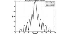
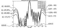
一例として、図1〜4に関して説明したような、第1のシングルビームアンテナをシミュレートする。ここで、各列の配列素子の数は12個(すなわち、N=12)であり、配列素子間の列離隔距離DH、したがって、異なる列に配置される第1及び第2の位相中心の間の距離は、半分の波長(DH=0.5λ)になるように選択され、90°の電力半値ビーム幅を有する放射素子パターンを仮定している。
As an example, a first single beam antenna as described with respect to FIGS. Here, the number of array elements in each column is twelve (ie, N = 12), and the column separation distance DH between the array elements, and therefore the first and second phase centers arranged in different columns. The distance between is chosen to be half the wavelength (DH = 0.5λ) and assumes a radiating element pattern with a half-power beamwidth of 90 °.
図5は、第1のシングルビームアンテナ及び、空間的ビーム指向角φ(α)について表される異なる角度αに対する可変位相:
αAC=−αBD=α
に対する予測方位角ビーム・パターンを示すものである。曲線(0;0)は、φ(αAC)=φ(αBD)=0を示し、曲線(17;−17)は、φ(αAC)=−φ(αBD)=17を示し、曲線(23;−23)は、φ(αAC)=−φ(αBD)=23を示し、曲線(27;−27)は、φ(αAC)=−φ(αBD)=27を示し、曲線(30;−30)は、φ(αAC)=−φ(αBD)=30を示す。方位角ビーム・パターンに対して、電力半値ビーム幅は、それぞれ、50、56、65、77及び90度である。FIG. 5 shows the variable phase for the first single beam antenna and the different angles α represented for the spatial beam pointing angle φ (α):
αAC = −αBD = α
Shows the predicted azimuth beam pattern for. Curve (0; 0) shows φ (αAC ) = φ (αBD ) = 0, curve (17; −17) shows φ (αAC ) = − φ (αBD ) = 17, The curve (23; −23) shows φ (αAC ) = − φ (αBD ) = 23, and the curve (27; −27) shows φ (αAC ) = − φ (αBD ) = 27. The curve (30; −30) shows φ (αAC ) = − φ (αBD ) = 30. For the azimuth beam pattern, the half-power beam widths are 50, 56, 65, 77, and 90 degrees, respectively.
図6は、第1のシングルビームアンテナの対応する仰角パターンを示す。5つのパターンは、互い重なっている。 FIG. 6 shows the corresponding elevation pattern of the first single beam antenna. The five patterns overlap each other.
図7は、第1のシングルビームアンテナと同じ構成だが、以下の式に従って設定される位相差αAC及びαBDを有する構成に対して予測される方位角ビーム・パターンを示す。
φ(αAC)−17°=φ(αBD)+17°=δ
式中、δ=[0°、10°、及び20°]である。曲線(17;−17)は、δ=0°、すなわち、φ(αAC)=17°、φ(αBD)=−17°を示し、同様に、曲線(27;−7)はδ=10°を示し、曲線(37;3)はδ=20°を示す。以上から、空間的ビーム指向角は、それぞれビームオフセットの0°、10°、及び20°に加えて+/−17°である。方位角ビーム・パターンに関して、電力半値帯域はすべてのオフセットに対して56度である。FIG. 7 shows the azimuth beam pattern expected for a configuration that is the same as the first single beam antenna but has phase differences αAC and αBD set according to the following equations:
φ (αAC ) −17 ° = φ (αBD ) + 17 ° = δ
Where δ = [0 °, 10 °, and 20 °]. Curve (17; -17) shows δ = 0 °, ie φ (αAC ) = 17 °, φ (αBD ) = − 17 °, and similarly curve (27; -7) shows δ = 10 ° is shown and the curve (37; 3) shows δ = 20 °. From the above, the spatial beam pointing angle is +/− 17 ° in addition to the beam offsets of 0 °, 10 °, and 20 °, respectively. For the azimuth beam pattern, the half-power band is 56 degrees for all offsets.
図8は、δ=[0°、10°、及び20°]を有する第1のシングルビームアンテナの対応する仰角パターンを示す。3つのパターンは、互い重なっている。 FIG. 8 shows the corresponding elevation pattern of the first single beam antenna with δ = [0 °, 10 °, and 20 °]. The three patterns overlap each other.
実施形態2
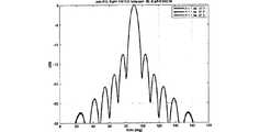
更なる一例として、図1〜4に関して説明したような、第2のシングルビームアンテナをシミュレートする。ここで、各列の配列素子の数は12個(すなわち、N=12)であり、配列素子間の列離隔距離DH、したがって、異なる列に配置される第1及び第2の位相中心間の距離は、7分の1の波長(DH=0.7λ)になるように選択され、65°の電力半値ビーム幅を有する放射素子パターンを仮定している。
As a further example, a second single beam antenna as described with respect to FIGS. Here, the number of array elements in each column is 12 (ie, N = 12), and the column separation distance DH between the array elements, and therefore between the first and second phase centers arranged in different columns. Is assumed to be a 1/7 wavelength (DH = 0.7λ), assuming a radiating element pattern with a power half-value beamwidth of 65 °.
図9は、第2のシングルビームアンテナ及び、空間的ビーム指向角φ(α)について表された異なる角度αに対する可変位相:
αAC=−αBD=α
に対する予測方位角ビーム・パターンを示すものである。曲線(0;0)は、φ(αAC)=φ(αBD)=0を示し、曲線(13;−13)は、φ(αAC)=−φ(αBD)=13を示し、曲線(19;−19)は、φ(αAC)=−φ(αBD)=19を示し、曲線(22;−22)は、φ(αAC)=−Φ(αBD)=22を示し、曲線(23;−23)は、φ(αAC)=−φ(αBD)=23を示す。方位角ビーム・パターンに対して、それぞれの電力半値帯域は、35、41、55、71、及び83度である。FIG. 9 shows the variable phase for the second single beam antenna and the different angle α expressed for the spatial beam pointing angle φ (α):
αAC = −αBD = α
Shows the predicted azimuth beam pattern for. Curve (0; 0) shows φ (αAC ) = φ (αBD ) = 0, curve (13; −13) shows φ (αAC ) = − φ (αBD ) = 13, The curve (19; −19) shows φ (αAC ) = − φ (αBD ) = 19, and the curve (22; −22) shows φ (αAC ) = − Φ (αBD ) = 22. The curve (23; −23) shows φ (αAC ) = − φ (αBD ) = 23. For the azimuth beam pattern, the respective half-power bands are 35, 41, 55, 71, and 83 degrees.
図10は、第2のシングルビームアンテナであるが、以下の式に従って設定される位相差αAC及びαBDを有する第2のシングルビームアンテナに対して予測される方位角ビーム・パターンを示す。
φ(αAC)−13°=φ(αBD)+13°=δ
式中、δ=[0°及び10°]である。曲線(13;−13)は、δ=0°、すなわち、φ(αAC)=13°及びφ(αBD)=−13°を示し、同様に、曲線(23;−3)は、δ=10°を示す。以上から、空間的ビーム指向角φは、それぞれビームオフセットの0°及び10°に加えて+/−13°である。方位角ビーム・パターンに関して、電力半値帯域は両ビームに対して41度である。FIG. 10 shows the predicted azimuth beam pattern for a second single beam antenna, but for a second single beam antenna with phase differences αAC and αBD set according to the following equations:
φ (αAC ) −13 ° = φ (αBD ) + 13 ° = δ
In the formula, δ = [0 ° and 10 °]. Curve (13; -13) shows δ = 0 °, ie φ (αAC ) = 13 ° and φ (αBD ) =-13 °, and similarly curve (23; -3) = 10 °. From the above, the spatial beam directing angle φ is +/− 13 ° in addition to the beam offset of 0 ° and 10 °, respectively. For the azimuth beam pattern, the half-power band is 41 degrees for both beams.
上述の例は、シングルビームアンテナを説明するものである。しかしながら、移動通信システムでは、デュアルビームアンテナを達成するために、すなわち、同じ領域をカバーするが直交する偏波を有する2つのビームを有するために、二重偏波アンテナを用いることは一般的である。 The above example illustrates a single beam antenna. However, in mobile communication systems it is common to use dual polarization antennas in order to achieve dual beam antennas, ie to have two beams that cover the same area but have orthogonal polarizations. is there.
図11は、M個のグループを有する本発明に係るアンテナ構成(左側)を示しており、各グループは、4つの二重偏波配列素子を有し、各二重偏波配列素子は、直交する偏波に対応づけられた第1の給電点及び第2の給電点を有し、図1に関連して説明したように2列に配置される第1及び第2の位相中心を有する。右側には、グループ「m」内の放射素子のインデックスを示す。素子は8個の線形配列を形成するように配置されており、各々がポートA〜Hに接続される。 FIG. 11 shows an antenna configuration (left side) according to the present invention having M groups, each group having four dual polarization array elements, each double polarization array element being orthogonal. The first feeding point and the second feeding point associated with the polarized wave to be polarized, and the first and second phase centers arranged in two rows as described with reference to FIG. On the right side, the indices of the radiating elements in the group “m” are shown. The elements are arranged to form eight linear arrays, each connected to ports AH.
図12は、ポートA及びポートBの配電網の例を示し、図13は、移相器及び電力結合器/分割器からなる、ビーム幅及びビーム指向調整用ビーム形成ネットワークを示す。 FIG. 12 shows an example of the distribution network of port A and port B, and FIG. 13 shows a beam forming network for adjusting beam width and beam orientation, which is composed of a phase shifter and a power combiner / divider.
図11〜13は、共に、本発明に係るアンテナの第2の実施形態を図示しており、この例では、各ビームが可変的なビーム幅及びビーム指向を有する、直交偏波のデュアルビームアンテナである。デュアルビームアンテナは、列離隔距離DHと行離隔距離DVとを有する、二重偏波配列素子31を2列で有するアンテナ構成30を備える。本実施形態では、各グループ「m」は、4つの垂直偏波放射素子Am、Cm、Em、及びGmと4つの水平偏波放射素子Bm、Dm、Fm、及びHm(m=1〜M)とを備え、Mは少なくとも1(M≧1)であり、好ましくは2よりも大きい(M>2)。各配列素子31は、2つの給電点(図示せず)、垂直偏波に対する第1の給電点及び水平偏波に対する第2の給電点を有する。第1の給電点は、第1の列32の放射素子Am及び放射素子Cmと、第2の列34の放射素子Em及び放射素子Gmとに接続される。第2の給電点は、第1の列32の放射素子Bm及び放射素子Dmと、第2の列34の放射素子Fm及び放射素子Hmとに接続される(図11参照)。FIGS. 11-13 both illustrate a second embodiment of an antenna according to the present invention, in this example dual beam antennas of orthogonal polarization, each beam having a variable beam width and beam orientation. It is. Dual-beam antenna includes a column separation distance DH and the row spacing distance DV, an
各列のすべての第2の放射素子の各給電点は、好ましくは仰角ビーム形成ネットワークとして実施される配電網を介して接続され、結果として、列A〜D及びE〜Hごとに4つのポートとなる(図11を参照)。図12は、好ましくは仰角ビーム形成ネットワークとして実施される配電網33A、33Bの例を挙げる。放射素子A1〜AMに接続される給電点は、垂直偏波を有するM個の素子の垂直線形配列を形成しているポートAに、配電網33Aを介して接続される。放射素子B1〜BMに接続される給電点は、垂直偏波を有するM個の素子の垂直線形配列を形成しているポートBに、配電網33Bを介して接続される。同様に、放射素子C1〜CMからH1〜HMに接続される給電点は、それぞれの配電網33C〜33Hを介してポートC〜Hに接続される。したがって、各列は全部で8つのポートA〜Hを提供する二重偏波配列素子の2つの交互配置されたM個の素子の線形配列から成る(図11及び12を参照)。Each feed point of every second radiating element in each row is preferably connected via a power distribution network implemented as an elevation beam forming network, resulting in four ports per row AD and EH. (See FIG. 11). FIG. 12 gives an example of a
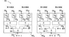
8つのポートであるポートA〜ポートHは、ここで、図13にて図示したように、デュアルビーム形成ネットワーク40(2つの別々のビーム形成ネットワーク401及び402を備える)の第1の実施形態によって、2つのアンテナ・ポートであるポート1及びポート2に結合される。別々のビーム形成ネットワーク401、402は、各々、アンテナ・ポート1及びポート2にそれぞれ接続されることを目的とする一次接続391、392を備える。各ポートA〜Hは、デュアルビーム形成ネットワーク40の各二次接続35A〜35Hに接続される。第1の列32のポートAに対応する垂直偏波線形配列と第2の列34のポートGに対応する垂直偏波線形配列とは、第1の二次電力結合器/分割器361と、それぞれ位相シフトαA及びαGを与える可変移相器37A及び37Gとを備える第1の移相ネットワークを介して、接続されている。第1の列32のポートDに対応する水平偏波線形配列と第2の列34のポートFに対応する水平偏波線形配列とは、第2の二次電力結合器/分割器362と、それぞれ位相シフトαD及びαFを与える可変移相器37D及び37Fとを備える第1の移相ネットワークを介して、接続されている。結合されたポートAG及びDFは、続いて、一次電力結合器/分割器38によって、一次接続391を介してアンテナ・ポート1に結合する。同様に、アンテナ・ポート2は、図13にて図示したように、ビーム形成ネットワーク402を用いて、ポートC、E、B及びHを結合することによって形成される。この構成により、アンテナ・ポート1及びポート2のアンテナ電力パターンのビーム幅及び/又は指向方向は、位相角αA、αB、αC、αD、αE、αF、αG、及びαHを適切に選択することによって変えてもよい。Eight ports A~ port H is a port here, as illustrated in Figure 13, a first embodiment of a dual beam forming network 40 (comprising two separate beam-forming
なお、以下に示すように、アンテナ・ポート1の水平及び垂直偏波放射素子間の位相差が、アンテナ・ポート2の水平及び垂直偏波放射素子間の位相差に対して適切に選択される場合、アンテナ・ポート1及びアンテナ・ポート2のビームは、全ての方位角に対して直交偏波を有することになる。 As shown below, the phase difference between the horizontal and vertical polarization radiating elements of the
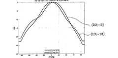
実施形態3
一例として、図11〜13に関して説明したような、第1のデュアルビームアンテナをシミュレートする。ここで、各列の配列素子の数は12個(すなわち、M=6)であり、配列素子間の列離隔距離DH、したがって、異なる列に配置される第1及び第2の位相中心間の距離は、半分の波長(DH=0.5λ)になるように選択され、90°の電力半値ビーム幅を有する放射素子パターンを仮定している。
As an example, a first dual beam antenna as described with respect to FIGS. 11-13 is simulated. Here, the number of array elements in each column is 12 (that is, M = 6), and the column separation distance DH between the array elements, and therefore between the first and second phase centers arranged in different columns. Is chosen to be half the wavelength (DH = 0.5λ), assuming a radiating element pattern with a half-power beamwidth of 90 °.
図14は、第1のデュアルビームアンテナ及び、空間的ビーム指向角φ(α)について表された異なる角度αに対する可変位相:
αA−αG=αF−αD=αB−αH=αE−αC=α
に対する予測方位角ビーム・パターンを示すものである。曲線1(0;0)及び曲線2(0;0)(各アンテナ・ポートに対して、φ=0を示す)は重複しており、同様に、曲線1(17;−17)及び曲線2(−17;17)、曲線1(23;−23)及び曲線2(−23;23)、曲線1(27;−27)及び曲線2(−27;27)、曲線1(30;−30)及び曲線2(−30;30)はペアのように一致する、すなわち、アンテナ・ポート1及び2に対応づけられた放射パターンは重複する。方位角ビーム・パターンに対して、電力半値帯域は、それぞれ、50、56、65、77及び90度である。FIG. 14 shows the variable phase for the first dual beam antenna and the different angles α expressed for the spatial beam pointing angle φ (α):
αA -αG = αF -αD = αB -αH = αE -αC = α
Shows the predicted azimuth beam pattern for. Curve 1 (0; 0) and curve 2 (0; 0) (indicating φ = 0 for each antenna port) overlap, and similarly, curve 1 (17; -17) and curve 2 (−17; 17), Curve 1 (23; −23) and Curve 2 (−23; 23), Curve 1 (27; −27) and Curve 2 (−27; 27), Curve 1 (30; −30) ) And curve 2 (−30; 30) match like a pair, ie, the radiation patterns associated with
空間的角度φと位相差αの関係は、
及びその逆である
によって与えられる。The relationship between the spatial angle φ and the phase difference α is
And vice versa
Given by.
図15は、第1のデュアルビームアンテナの対応する仰角パターンを示す。 FIG. 15 shows the corresponding elevation angle pattern of the first dual beam antenna.
図16は、第1のデュアルビームアンテナと同じ構成だが、以下の式に従って設定される位相差αA−αG、αD−αF、αB−αH、及びαC−αEを有する構成に対する予測方位角ビーム・パターンを示す。
φ(αA−αG)−17°=φ(αD−αF)+17°=φ(αC−αE)+17°=φ(αB−αH)−17°=δ
式中、δ=[0°、10°、及び20°]である。曲線1(17;−17)は曲線2(−17;17)に等しく、δ=0°、すなわち、φ(αA−αG)=φ(αB−αH)=17°及びφ(αD−αF)=φ(αC−αE)=−17°であることを示し、同様に、曲線1(27;−7)は曲線2(−7;27)に等しく、δ=0°であり、曲線1(37;3)は曲線2(3;37)に等しく、δ=20°であることを示す。空間的ビーム指向角φ(ポートAG、BH、CE及びBHに関して)は、アンテナビームオフセットの0°、10°、及び20°それぞれに加えて+/−17°である。方位角ビーム・パターンに関して、電力半値帯域はすべての設定に対して56度である。FIG. 16 has the same configuration as the first dual beam antenna, but has phase differences αA −αG , αD −αF , αB −αH , and αC −αE set according to the following equations. Figure 3 shows the predicted azimuth beam pattern for the configuration.
φ (αA −αG ) −17 ° = φ (αD −αF ) + 17 ° = φ (αC −αE ) + 17 ° = φ (αB −αH ) −17 ° = δ
Where δ = [0 °, 10 °, and 20 °]. Curve 1 (17; -17) is equal to curve 2 (-17; 17), δ = 0 °, ie φ (αA −αG ) = φ (αB −αH ) = 17 ° and φ ( αD −αF ) = φ (αC −αE ) = − 17 °, and similarly, curve 1 (27; −7) is equal to curve 2 (−7; 27), and δ = 0 °, indicating that curve 1 (37; 3) is equal to curve 2 (3; 37) and δ = 20 °. The spatial beam pointing angle φ (with respect to ports AG, BH, CE and BH) is +/− 17 ° in addition to the
図17は、対応する仰角パターンを示す。 FIG. 17 shows the corresponding elevation angle pattern.
図18は、本発明に係る第2のデュアルビームアンテナを得るために図11及び図12に図示したように配電網に接続されることを目的とする本発明に係るデュアルビーム形成ネットワークの第2の実施形態を示すものであり、ポートAGをポートBHに結合してアンテナ・ポート1を形成し、同様にポートCEをポートDFに結合してアンテナ・ポート2を形成する。 FIG. 18 illustrates a second dual beam forming network according to the present invention intended to be connected to a distribution network as illustrated in FIGS. 11 and 12 to obtain a second dual beam antenna according to the present invention. In this embodiment, the port AG is coupled to the port BH to form the
図13において説明された構成の代わりに図18の構成を用いる場合、図14〜17にて開示したように同様の方位角ビーム・パターンが得られる。 If the configuration of FIG. 18 is used instead of the configuration described in FIG. 13, similar azimuth beam patterns are obtained as disclosed in FIGS.
図19は、R個のグループを有する、本発明に係るアンテナ構成(左側)を示すものであり、各グループは、6個の二重偏波配列素子を有する。右側には、グループ「r」内の放射素子のインデックスを示す。素子は12個の線形配列を形成するように配置されており、各々がポートA〜Lに接続される。 FIG. 19 shows an antenna configuration (left side) according to the present invention having R groups, each group having six dual polarization array elements. On the right side, the index of the radiating elements in the group “r” is shown. The elements are arranged to form twelve linear arrays, each connected to ports A-L.
図20は、移相器及び電力結合器/分割器からなる、本発明に係るビーム幅及びビーム指向調整用ビーム形成ネットワークを示す。 FIG. 20 shows a beam forming network for beam width and beam pointing adjustment according to the present invention, consisting of a phase shifter and a power combiner / splitter.
図19及び図20は、共に、本発明に係るアンテナの第3の実施形態を図示しており、この例では、各ビームが可変的なビーム幅及びビーム指向を有する、直交偏波を有するデュアルビームアンテナである。デュアルビームアンテナは、列離隔距離DHと行離隔距離DVとを有する、二重偏波配列素子51のR個のグループを3列52〜54で有するアンテナ構成50を備える。本実施形態では、各グループ「r」は、6個の垂直偏波放射素子Ar、Cr、Er、Gr、Ir、及びKrと、6個の水平偏波放射素子Br、Dr、Fr、Hr、Jr、及びLr(r=1〜R)とを備え、Rは少なくとも1(R≧1)であり、好ましくは2よりも大きい(R>2)。各配列素子は、2つの給電点である、垂直偏波に対する第1の給電点及び水平偏波に対する第2の給電点を有する(図19を参照)。図11〜13に関連して説明されたアンテナの第2の実施形態との違いは、この例におけるアンテナは2列ではなく3列で二重偏波配列素子を備えることであるが、可変的なビーム幅及びビーム指向を達成する原理は同じことである。FIGS. 19 and 20 both illustrate a third embodiment of an antenna according to the present invention, in this example dual beams with orthogonal polarization, each beam having a variable beam width and beam orientation. It is a beam antenna. Dual-beam antenna includes an
各列のすべての第2の放射素子の各給電点は、好ましくは仰角ビーム形成ネットワークとして実施される配電網を介して接続され、結果として、列A〜D、E〜H、及びI〜Lごとにそれぞれ4つのポートとなる(図19を参照)。したがって、アンテナ素子ポートA1〜ARは、第1の配電網(図示せず)を介して、垂直偏波を有するR個の素子の垂直線形配列を形成するポートAに接続される。アンテナ素子ポートB1〜BRは、第2の配電網(図示せず)を介して、水平偏波を有するR個の素子の水平線形配列を形成するポートBに接続される。同様に、アンテナ素子C1〜CRからL1〜LRは、ポートC〜Lを形成する個々の仰角ビーム形成ネットワークを介して接続される。したがって、各列は全部で12個のポートにA〜Lを提供する二重偏波素子の2つの交互配置されたR個の素子の線形配列から成る(図19を参照)。Each feed point of every second radiating element in each column is preferably connected via a distribution network implemented as an elevation beam forming network, resulting in columns AD, EH and IL Each has four ports (see FIG. 19). Therefore, the antenna element ports A1 to AR are connected to a port A forming a vertical linear array of R elements having vertical polarization via a first distribution network (not shown). The antenna element ports B1 to BR are connected to a port B forming a horizontal linear array of R elements having horizontal polarization via a second power distribution network (not shown). Similarly, the antenna elementsC 1 -C fromRL 1 ~LR are connected via individual elevation beam forming network for forming a port C~L. Thus, each column consists of a linear array of two interleaved R elements of dual polarization elements that provide A to L for a total of 12 ports (see FIG. 19).
12個のポートであるポートA〜ポートLは、図20にて図示したように、ビーム形成ネットワーク60(2つの別々のビーム形成ネットワーク601及び602を備える)の第3の実施形態によって、2つのアンテナ・ポートであるポート1及びポート2に結合される。別々のビーム形成ネットワーク601、602は、各々、アンテナ・ポート1及びポート2にそれぞれ接続されることを目的とする一次接続591、592を備える。各ポートA〜Lは、デュアルビーム形成ネットワーク60の各二次接続55A〜55Lに接続される。第1の列52のポートAに対応する垂直偏波線形配列、第2の列53のポートGに対応する垂直偏波線形配列、及び、第3の列54のポートIに対応する垂直偏波線形配列は、第1の二次電力結合器/分割器561と、それぞれ位相シフトαA、αG、及びαIを与える可変移相器57A、57G、及び57Iとを備える第1の移相ネットワークを介して、接続される。第1の列52のポートBに対応する水平偏波線形配列、第2の列53のポートHに対応する水平偏波線形配列、及び、第3の列54のポートJに対応する水平偏波線形配列は、第2の二次電力結合器/分割器562と、それぞれ位相シフトαB、αH、及びαJを与える可変移相器57B、57H、及び57Jとを備える第2の移相ネットワークを介して、接続される。Twelve ports, port A through port L, as illustrated in FIG. 20, according to a third embodiment of the beam forming network 60 (comprising two separate
結合されたポートAGI及びDFJは、続いて、一次電力結合器/分割器58によって、一次接続591を介してアンテナ・ポート1に結合される。同様に、アンテナ・ポート2は、図20にて図示したように、ビーム形成ネットワーク602を用いて、ポートC、E、K、D、F、及びLを結合することによって形成される。上述の例と同様で、この構成によって、以下に示すように、位相角αA〜αLを適切に選択することによって、アンテナ・ポート1及びポート2のアンテナ電力パターンのビーム幅及び/又は指向方向を変更することが可能になる。Coupled port AGI and DFJ is subsequently by the primary power combiner /
実施形態4
一例として、図19〜20に関して説明したような、第2のデュアルビームアンテナをシミュレートする。ここで、各列の配列素子の数は12個(すなわち、R=6)であり、配列素子間の列離隔距離DH、したがって、異なる列に配置される第1及び第2の位相中心の間の距離は、半分の波長(DH=0.5λ)になるように選択され、90°の電力半値ビーム幅を有する放射素子パターンを仮定している。
As an example, a second dual beam antenna as described with respect to FIGS. 19-20 is simulated. Here, the number of array elements in each column is twelve (ie, R = 6), and the column separation distance DH between the array elements, and therefore the first and second phase centers arranged in different columns. The distance between is chosen to be half the wavelength (DH = 0.5λ) and assumes a radiating element pattern with a half-power beamwidth of 90 °.
図21は、第2のデュアルビームアンテナ及び可変位相に対する予測方位角ビーム・パターンを示す。 FIG. 21 shows the predicted azimuth beam pattern for the second dual beam antenna and variable phase.
同じ空間的離隔距離を有しているため、線形スロープ、すなわち、2つの隣接する配列素子間の同じ位相差が与えられる。曲線1(0;0)及び曲線2(0;0)(各アンテナ・ポートに対して、φ=0を示す)は重複しており、同様に曲線1(10;−10)及び曲線2(−10;10)、曲線1(16;−16)及び曲線2(−16;16)、曲線1(19;−19)及び曲線2(−19;19)はペアのように一致する、すなわち、アンテナ・ポート1及び2に対応づけられた放射パターンは重複する。方位角ビーム・パターンに対して、それぞれの電力半値帯域は、35、41、55、及び67度である。 Having the same spatial separation gives a linear slope, ie the same phase difference between two adjacent array elements. Curve 1 (0; 0) and curve 2 (0; 0) (indicating φ = 0 for each antenna port) are overlapping, and similarly curve 1 (10; -10) and curve 2 ( −10; 10), curve 1 (16; −16) and curve 2 (−16; 16), curve 1 (19; −19) and curve 2 (−19; 19) are matched like a pair, ie The radiation patterns associated with
図22は、第2のデュアルビームアンテナの対応する仰角パターンを示す。 FIG. 22 shows the corresponding elevation angle pattern of the second dual beam antenna.
図1、図11及び図19に関連して説明された配列素子は、二重偏波放射素子を有する配列素子として図示されているが、本発明は、これに限られるものではないことに留意されたい。本明細書から当業者には自明であるように、配列素子が重なっていれば、単一偏波放射素子を有する配列素子を用いて、同様な挙動を生じさせることは可能である。 Note that although the array elements described in connection with FIGS. 1, 11 and 19 are illustrated as array elements having dual-polarized radiating elements, the present invention is not limited thereto. I want to be. As will be apparent to those skilled in the art from this specification, if the array elements overlap, it is possible to produce similar behavior using array elements having single polarization radiating elements.
図23及び図24は、どのようにアンテナが2つの配列素子(シングルビームアンテナ用)に、又は、4つの配列素子(デュアルビームアンテナ用)に分けられるかを図示する。配列素子は、第1の偏波に対応づけられた第1の給電点、及び、第1の偏波に直交する第2の偏波に対応づけられた第2の給電点を有する。網掛け部分は、各配列素子を実施するために必要なアンテナ表面を示す。 23 and 24 illustrate how the antenna can be divided into two array elements (for single beam antennas) or four array elements (for dual beam antennas). The array element has a first feeding point associated with the first polarization and a second feeding point associated with the second polarization orthogonal to the first polarization. The shaded portion indicates the antenna surface necessary for implementing each array element.
図23において、シングルアンテナ・ポート1を設けたアンテナは、アンテナ表面に配置される2つの配列素子を備える。給電点は、図1のグループのインデックスを参照して図示されている。 In FIG. 23, the antenna provided with the
アンテナ構成は、隣同士に配置される2つの配列素子によって実現してもよい。第1の偏波に対応づけられた第1の給電点「A」及び第2の偏波に対応づけられた第2の給電点「B」を有する第1の配列素子と、第1の偏波に対応づけられた第1の給電点「C」及び第2の偏波に対応づけられた第2の給電点「D」を有する第2の配列素子である。配列素子ごとに、異なる偏波に対する位相中心が、同じ列に配列されているものと考えてもよい。 The antenna configuration may be realized by two array elements arranged next to each other. A first array element having a first feed point “A” associated with the first polarization and a second feed point “B” associated with the second polarization; A second array element having a first feed point “C” associated with a wave and a second feed point “D” associated with a second polarization. It may be considered that the phase centers for different polarizations are arranged in the same column for each array element.
同じアンテナ構成は、互い重なり合う2つの配列素子によって実現してもよい。第1の偏波に対応づけられた第1の給電点「A」及び第2の偏波に対応づけられた第2の給電点「D」を有する第1の配列素子と、第1の偏波に対応づけられた第1の給電点「C」及び第2の偏波に対応づけられた第2の給電点「B」を有する第2の配列素子である。配列素子ごとに、異なる偏波に対する位相中心が、異なる列に配列されているものと考えてもよい。 The same antenna configuration may be realized by two overlapping array elements. A first array element having a first feed point “A” associated with the first polarization and a second feed point “D” associated with the second polarization; A second array element having a first feed point “C” associated with a wave and a second feed point “B” associated with a second polarization. It may be considered that the phase centers for different polarizations are arranged in different columns for each array element.
配列素子は、また、給電ネットワークを介して各偏波に共通の給電点に相互接続する複数の放射素子を備えてもよい。これの一例を、図24にて説明する。 The array element may also include a plurality of radiating elements interconnected to a common feed point for each polarization via a feed network. An example of this will be described with reference to FIG.
当該アンテナは、2つの列に配置される12個の二重偏波放射素子を備える。放射素子は、例えば、図13又は図18に関連して開示したように、ビーム形成ネットワークを介して2つのアンテナ・ポート1及び2に接続される。給電点は、図11のグループのインデックスを参照して図示されている。 The antenna includes 12 dual-polarized radiating elements arranged in two rows. The radiating elements are connected to the two
このアンテナ構成は、図11〜13に関連してすでに説明したが、多数の異なる方法で実現されてもよい。図24には、変形例が4つの配列素子を含んで示されおり、アンテナ構成を実現するために重なり合っている。第1の配列素子は、第1の偏波を有する第1の列において、全ての第2の放射素子に接続される第1の給電点「A」と、第2の偏波を有する第2の列において、全ての第2の放射素子に接続される第2の給電点「F」と、を有する。同様に、第2の配列素子は、給電点D及びGを有し、第3の配列素子は、給電点B及びEを有し、第4の配列素子は、給電点C及びHを有する。 This antenna configuration has already been described in connection with FIGS. 11-13, but may be implemented in a number of different ways. FIG. 24 shows a modification including four array elements, which are overlapped to realize an antenna configuration. The first array element includes a first feeding point “A” connected to all the second radiating elements in the first row having the first polarization, and a second having the second polarization. , The second feeding point “F” connected to all the second radiating elements. Similarly, the second array element has feeding points D and G, the third array element has feeding points B and E, and the fourth array element has feeding points C and H.
上記した実施形態では、単一偏波又は二重偏波配列素子によって生じる垂直及び水平の偏波として、異なる偏波の例をあげた。放射素子は、最も簡単な実施態様を図示し、更に、発明の概念を明確に記載するために用いた。しかし、2つ偏波の差が大体90度(すなわち基本的に直交)である限り、他の偏波(例えば+45度/−45度又は+60度/−30度)を有する配列素子を用いてもよいことに留意されたい。さらに、第1の列の0/+90度の偏波を有する配列素子と、第2の列の−20/+70度の偏波を有する配列素子とを有することも考えられる。その場合、異なる列に配置される配列素子の全ての偏波が同じになるように、配列素子の給電を適合させる必要がある。これは、偏波変成器を直接配列素子ポートに適用することで、全ての配列素子が同じ偏波を有するようにすることで達成してもよい。偏波変成器は、好ましくは、配列素子の一部であると見なされ、それによって偏波は全ての配列素子に対して同一となる。 In the above-described embodiment, examples of different polarizations are given as vertical and horizontal polarizations generated by a single polarization or double polarization array element. The radiating element was used to illustrate the simplest embodiment and to clearly describe the inventive concept. However, as long as the difference between the two polarizations is approximately 90 degrees (ie, basically orthogonal), using an array element having another polarization (eg, +45 degrees / −45 degrees or +60 degrees / −30 degrees). Note that it is also possible. Furthermore, it is conceivable to have an array element having a polarization of 0 / + 90 degrees in the first column and an array element having a polarization of −20 / + 70 degrees in the second column. In that case, it is necessary to adapt the feeding of the array elements so that all the polarizations of the array elements arranged in different rows are the same. This may be achieved by applying a polarization transformer directly to the array element port so that all array elements have the same polarization. The polarization transformer is preferably considered to be part of the array element, so that the polarization is the same for all array elements.
図25も、図26a〜26dに関連して、配列素子の他の構成を用いて、上記と同じ特性を有するアンテナを得る可能性を図示するものである。 FIG. 25 also illustrates, in conjunction with FIGS. 26a-26d, the possibility of obtaining an antenna having the same characteristics as described above using other arrangements of array elements.
図25は、2列に配置される配列素子を有する一般的なアンテナ構成70を示す。各列は、10個の配列素子を備える。配列素子X1〜X10は第1の列に配置され、配列素子Y1〜Y10は第2の列に配置される。この一般的な例において、各配列素子は二重偏波されており、第1の給電点71(実線によって示される)及び第2の給電点72(破線によって示される)を有する。第1の偏波を有する配列素子の中の放射素子は、第1の給電点71に接続され、第1の偏波に直交する第2の偏波を有する放射素子は、第2の給電点72に接続される。FIG. 25 shows a
配列素子X1〜X10の給電点は、配電網(図示せず)を介して多くのポートに接続される。配列素子Y1〜Y10の給電点は、配電網(図示せず)を介して同数のポートに接続される。ポートの数は、上記のように、何個の配列素子がグループに含まれるかに依存し、グループに二重偏波を有する2つの配列素子のみが含まれる場合は、各列の配列素子の給電点は、2つのポートに接続されることになる(図1を参照)。しかし、グループに二重偏波を有する4つの配列素子が含まれる場合は、各列の配列素子の給電点は、4つのポートに接続されることになる(図11を参照)。The feeding points of the array elements X1 to X10 are connected to many ports through a power distribution network (not shown). The feeding points of the array elements Y1 to Y10 are connected to the same number of ports via a power distribution network (not shown). The number of ports depends on how many array elements are included in the group as described above. When the group includes only two array elements having dual polarization, the number of array elements in each column The feeding point is connected to two ports (see FIG. 1). However, when the group includes four array elements having dual polarization, the feeding points of the array elements in each column are connected to four ports (see FIG. 11).
列間の水平距離DH及び各行間の垂直距離DVは、通常、マルチビームアンテナを設計するときに決定された構造的なパラメータである。これらは好ましくは0.3λと1λの間に設定される。しかしながら、水平距離及び/又は垂直距離を変えることで、マルチビームアンテナの特性を変更し得るマルチビームアンテナを設計することができる。Horizontal distance DH and the vertical distance DV of each line spacing between columns is usually a structural parameters determined when designing a multi-beam antenna. These are preferably set between 0.3λ and 1λ. However, it is possible to design a multi-beam antenna that can change the characteristics of the multi-beam antenna by changing the horizontal distance and / or the vertical distance.
図25に図示される配列素子は、放射素子のn×mマトリクスを有する部分配列として実現されてもよい。ここで、n及びmは1以上の整数である(n,m≧1)。各部分配列内の各放射素子は、それぞれの給電点に接続される。 The array element illustrated in FIG. 25 may be realized as a partial array having an nxm matrix of radiating elements. Here, n and m are integers of 1 or more (n, m ≧ 1). Each radiating element in each subarray is connected to a respective feed point.
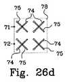
図26a〜26dは、図25に示されるアンテナに用い得る配列素子の4つの例を示す。例示された配列素子は全て、二重偏波放射素子を備えるものであり、したがって、2つの給電点71及び72を備える。図23及び図24に関して図示したように、例示された配列素子のそれぞれは、単一偏波放射素子を有してもよいことに留意されたい。 26a-26d show four examples of array elements that can be used in the antenna shown in FIG. All of the illustrated array elements comprise dual-polarized radiating elements and thus comprise two
図26aは、第1の偏波を有する第1の放射素子74(1×1のマトリクス)に接続される第1の給電点71、及び、第1の偏波に直交する第2の偏波を有する第2の放射素子75に接続される第2の給電点72を有する簡単な二重偏波配列素子73を図示する。 FIG. 26a shows a
図26bは、第1の偏波を有する第1の放射素子74の2×1のマトリクスに接続される第1の給電点71、及び、第1の偏波に直交する第2の偏波を有する第2の放射素子75の2×1のマトリクスに接続される第2の給電点72を有する二重偏波配列素子76を図示する。 FIG. 26 b shows a
図26cは、第1の偏波を有する第1の放射素子74の1×2のマトリクスに接続される第1の給電点71、及び、第1の偏波に直交する第2の偏波を有する第2の放射素子75の1×2のマトリクスに接続される第2の給電点72を有する二重偏波配列素子77を図示する。 FIG. 26 c shows a
図26dは、第1の偏波を有する第1の放射素子74の2×2のマトリクスに接続される第1の給電点71、及び、第1の偏波に直交する第2の偏波を有する第2の放射素子75の2×2のマトリクスに接続される第2の給電点72を有する二重偏波配列素子78を図示する。 FIG. 26d shows the
図25において説明される一般的なアンテナ構成の配列素子は全て、例えば、同じタイプの二重偏波配列素子77を有していてもよいが、当然、アンテナ構成の全ての配列素子が異なっていることも可能である。重要な特徴は、配列素子が、直交する偏波に対応づけられた2つの給電点を備え、各偏波に対応づけられた位相中心が、上記のように、少なくとも2列で配置される、ということである。 All the array elements having the general antenna configuration illustrated in FIG. 25 may have, for example, the same type of dual
実施形態5
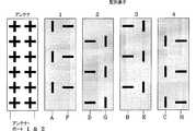
図27は、アンテナ構成81、4つの配電網82A〜82D、及びビーム形成ネットワーク83を備える、本発明に係る第3のシングルビームアンテナ80を示す。当該アンテナは、2つの異なるタイプ78及び79の、8個の交互配置された配列素子の一列を備える。各配列素子は、第1の偏波に対応づけられた第1の給電点(及び、第1の位相中心)、及び、第1の偏波に直交する第2の偏波に対応づけられた第2の給電点(及び、第2の位相中心)を有する。第1のタイプの配列素子78の第1の位相中心は、第1の列に配置され、第2の配列素子79の第1の位相中心は、第2の列に配置される。配列素子の第1のタイプ78及び第2のタイプ79の第2の位相中心には正反対のものを適用する。各配電網は、同じタイプの配列素子のそれぞれの給電点をポート(A〜D)に接続するように構成され、ビーム形成ネットワーク83を介して、ポート(A〜D)をシングルアンテナ・ポート1に接続する。
FIG. 27 shows a third
この例では、配列素子は4つのグループ1〜4に分けられ、各配列素子は2つの単一偏波放射素子を備え、各単一偏波放射素子は、それぞれの給電点に接続される。各グループ「s」は、垂直偏波放射素子As及び水平偏波放射素子Bsを有する第1のタイプの配列素子78と、水平偏波放射素子Cs及び垂直偏波放射素子Dsを有する第2のタイプの配列素子79と、を備える。放射素子As及びCsの位相中心は第1の列84に配置され、放射素子Bs及びDsの位相中心は第2の列85に配置される。第1の列84の垂直放射素子、すなわち、A1〜A4は、第1の配電網82Aを介してポートAに接続され、第1の列84の水平放射素子、すなわち、C1〜C4は、第2の配電網82Cを介して、ポートCに接続される。同様のことが、第2の列85の放射素子にも当てはまる。すなわち、放射素子B1〜B4は、第3の配電網を介してポートBに接続され、放射素子D1〜D4は、第4の配電網を介してポートDに接続される。配電網は、好ましくは、別々の仰角ビーム形成ネットワークとして実施される。In this example, the array elements are divided into four
4つのポートであるポートA〜ポートDは、ビーム形成ネットワーク83によって、1つのアンテナ・ポートであるポート1に結合する。ビーム形成ネットワーク83は、アンテナ・ポート1及び4個の二次接続86A〜86Dに接続されることを目的とする一次接続89を備える。各ポートA、B、C、及びDは、ビーム形成ネットワーク83のそれぞれの二次接続に接続される。第1の列84のポートAに対応する垂直偏波線形配列と第2の列85のポートDに対応する垂直偏波線形配列とは、第1の一体型電力結合器/分割器兼移相装置871を介して接続される(図4に関連して説明されたものと同様である)。第1の列84のポートCに対応する水平偏波線形配列と第2の列85のポートBに対応する水平偏波線形配列とは、第2の一体型電力結合器/分割器兼移相装置872を介して接続される。結合されたポートAD及びBDは、続いて、異なる偏波を有する放射素子間で電力を結合/分割する一次電力結合器/分割器88を介してアンテナ・ポート1に接続される。Four ports, port A to port D, are coupled to
実施形態6
図28は、配列素子が垂直方向であり、第1のタイプの配列素子78が第1の列94に配置され、第2のタイプの配列素子79が第2の列95に配置されること以外、図27において説明されたものと同様なアンテナ構成を備える、本発明に係る第3のデュアルビームアンテナ90を示す。配列素子は、2つのグループにのみ分けられて、各グループ「t」は4つの配列素子を有する。単一偏波放射素子At、Bt、Et、及びFtは、第1のセットに属し、単一偏波放射素子Ct、Dt、Gt、及びHtは、第2のセットに属す。第1のタイプの配列素子78の第1の位相中心及び第2の位相中心は、第1の列94に配置され、第2のタイプの配列素子79の第1の位相中心及び第2の位相中心は、第2の列95に配列されるものとする。Embodiment 6
In FIG. 28, the array elements are in the vertical direction, except that the first
8個のポート、すなわちポートA〜ポートHは、2つのビーム形成ネットワーク931及び932によって、2つのアンテナ・ポート、すなわちポート1及びポート2に結合する。各ビーム形成ネットワークは、それぞれのアンテナ・ポート及び4個の二次接続に接続されることを目的とする一次接続を備える。各ポートA〜Hは、ビーム形成ネットワークのそれぞれの二次接続に接続される。各列における全ての第2の配列素子のそれぞれの給電点は、好ましくは仰角ビーム形成ネットワークとして実施される別々の配電網92A〜92Hを介して、ポートA〜Hに接続される(図28を参照)。8 ports, namely port A~ port H is the two
4つのポートA、B、E、及びFは、第1のビーム形成ネットワーク931に接続される。第1の列94のポートAに対応する垂直偏波線形配列と第2の列95のポートFに対応する垂直偏波線形配列とは、第1の一体型電力結合器/分割器兼移相装置971を備える第1の移送ネットワークを介して接続される(図4に関連して説明されたものと同様である)。第1の列94のポートBに対応する水平偏波線形配列と第2の列95のポートEに対応する水平偏波線形配列とは、第2の一体型電力結合器/分割器兼移相装置872を備える第2の移送ネットワークを介して接続される。結合されたポートAF及びBEは、続いて、第1のセットに属す放射素子間で電力を結合/分割し、異なる偏波を有する一次電力結合器/分割器981を介してアンテナ・ポート1に接続される。The four ports A, B, E, and F are connected to thefirst beam forming network 931. The vertical polarization linear array corresponding to port A in the
同様に、ポートC、D、G、及びHは、第2のビーム形成ネットワーク932を介してアンテナ・ポート2に接続される。Similarly, ports C, D, G, and H are connected to
上記した実施形態の全てにおいて、電気的傾斜を実施することが可能であるが、本発明に対して更なる影響はない。さらにまた、図3、4、13、18、20、27、及び28に関連して説明される結合器/分割器は、変数(又は、少なくとも固定で不均等の電力分割)を有してもよい。不均等な結合/分割は、一次及び二次結合器/分割器に対して実施してもよいが、一次結合器/分割器に対する方がより効果的である。 In all of the embodiments described above, it is possible to implement an electrical ramp, but there is no further influence on the present invention. Furthermore, the combiner / divider described in connection with FIGS. 3, 4, 13, 18, 20, 27, and 28 may have variables (or at least a fixed and unequal power split). Good. Uneven combining / splitting may be performed for primary and secondary combiners / splitters, but is more effective for primary combiners / splitters.
上述の実施形態に関連して説明された各給電ネットワークは、ビーム形成ネットワークと複数の配電網とを備える。各配電網は、ビーム形成ネットワークの各二次接続を、各列に配置される第1の位相中心を有する接続配列素子の第1の給電点に排他的に接続する、又は、ビーム形成ネットワークのそれぞれの二次接続を、各列に配置される第2の位相中心を有する接続配列素子の第2の給電点に排他的に接続する。 Each feed network described in connection with the above embodiments comprises a beam forming network and a plurality of distribution networks. Each distribution network exclusively connects each secondary connection of the beam forming network to a first feed point of a connection array element having a first phase center arranged in each column, or of the beam forming network Each secondary connection is exclusively connected to a second feed point of a connection array element having a second phase center arranged in each column.
Claims (15)
Translated fromJapanese第1の偏波に対応づけられた第1の位相中心及び第2の偏波に対応づけられた第2の位相中心を有し、前記配列素子の第1及び第2の位相中心は、少なくとも2列に配置される、各配列素子と、
1以上のアンテナ・ポートであって、各アンテナ・ポートは、それぞれの給電ネットワークを介して前記少なくとも2列に配置される第1の位相中心及び第2の位相中心を有する少なくとも2つの配列素子の第1及び第2の給電点に接続される、1以上のアンテナ・ポートと、を備える可変ビーム特性を有するアンテナであって、
前記それぞれの給電ネットワークは、
それぞれのアンテナ・ポートに接続される一次接続及び少なくとも4つの二次接続を有するビーム形成ネットワークを備え、前記ビーム形成ネットワークは、前記接続配列素子の第1の給電点と第2の給電点との間で電力を分け、異なる列に配置される位相中心を有する接続配列素子の第1の給電点間、及び、異なる列に配置される第2の位相中心を有する接続配列素子の第2の給電点間の位相シフト差を制御するよう構成されることを特徴とする、可変ビーム特性を有するアンテナ。A plurality of array elements, each array element being associated with a first feed point associated with the first polarization and a second polarization orthogonal to the first polarization; A plurality of array elements comprising a second feeding point;
A first phase center associated with the first polarization and a second phase center associated with the second polarization, wherein the first and second phase centers of the array element are at least Each array element arranged in two rows;
One or more antenna ports, each antenna port comprising at least two array elements having a first phase center and a second phase center arranged in the at least two rows via a respective feed network An antenna having variable beam characteristics comprising one or more antenna ports connected to first and second feed points,
Each of the power supply networks is
A beam forming network having a primary connection connected to each antenna port and at least four secondary connections, the beam forming network comprising a first feed point and a second feed point of the connection array element; Power is divided between the first feeding points of the connecting array elements having phase centers arranged in different columns and the second feeding of the connecting array elements having second phase centers arranged in different columns An antenna having variable beam characteristics, characterized in that it is configured to control a phase shift difference between points.
Applications Claiming Priority (1)
| Application Number | Priority Date | Filing Date | Title |
|---|---|---|---|
| PCT/EP2010/000756WO2011095184A1 (en) | 2010-02-08 | 2010-02-08 | An antenna with adjustable beam characteristics |
Publications (2)
| Publication Number | Publication Date |
|---|---|
| JP2013519276Atrue JP2013519276A (en) | 2013-05-23 |
| JP5584783B2 JP5584783B2 (en) | 2014-09-03 |
Family
ID=42938432
Family Applications (1)
| Application Number | Title | Priority Date | Filing Date |
|---|---|---|---|
| JP2012551497AExpired - Fee RelatedJP5584783B2 (en) | 2010-02-08 | 2010-02-08 | Antenna with variable beam characteristics |
Country Status (9)
| Country | Link |
|---|---|
| US (2) | US9768494B2 (en) |
| EP (1) | EP2534728A1 (en) |
| JP (1) | JP5584783B2 (en) |
| KR (1) | KR101665158B1 (en) |
| CN (1) | CN102742073B (en) |
| BR (1) | BR112012019194B1 (en) |
| MX (1) | MX2012008424A (en) |
| PH (1) | PH12012501396B1 (en) |
| WO (1) | WO2011095184A1 (en) |
Cited By (1)
| Publication number | Priority date | Publication date | Assignee | Title |
|---|---|---|---|---|
| JP2020527895A (en)* | 2017-07-17 | 2020-09-10 | テレフオンアクチーボラゲット エルエム エリクソン(パブル) | Antenna configuration and method for beam formation |
Families Citing this family (53)
| Publication number | Priority date | Publication date | Assignee | Title |
|---|---|---|---|---|
| ES2747937T3 (en)* | 2008-11-20 | 2020-03-12 | Commscope Technologies Llc | Double beam sector antenna and set |
| US9086476B1 (en) | 2009-03-25 | 2015-07-21 | Raytheon Company | Method and apparatus for rejecting intermodulation products |
| US8866686B1 (en) | 2009-03-25 | 2014-10-21 | Raytheon Company | Methods and apparatus for super-element phased array radiator |
| US9373888B1 (en) | 2009-03-25 | 2016-06-21 | Raytheon Company | Method and apparatus for reducing sidelobes in large phased array radar with super-elements |
| WO2011114189A1 (en)* | 2010-03-17 | 2011-09-22 | Nokia Corporation | Method and apparatus for testing received signals in a radio signal positioning system |
| EP2715868B1 (en)* | 2011-06-01 | 2018-12-26 | Telefonaktiebolaget LM Ericsson (publ) | A signal combiner, method and computer program product |
| US9136578B2 (en)* | 2011-12-06 | 2015-09-15 | Viasat, Inc. | Recombinant waveguide power combiner / divider |
| CN105703054B (en)* | 2011-12-13 | 2018-08-24 | 瑞典爱立信有限公司 | Node at least two antenna arrays in cordless communication network |
| US9263794B2 (en)* | 2011-12-13 | 2016-02-16 | Telefonaktiebolaget L M Ericsson (Publ) | Node in a wireless communication network with at least two antenna columns |
| US9070964B1 (en)* | 2011-12-19 | 2015-06-30 | Raytheon Company | Methods and apparatus for volumetric coverage with image beam super-elements |
| CN103873123B (en)* | 2012-12-12 | 2017-05-03 | 中国移动通信集团北京有限公司 | Antenna radiation beam transmitting method and device |
| BR112015024425A2 (en) | 2013-04-25 | 2017-07-18 | Ericsson Telefon Ab L M | sky spider roofing knot |
| US9379446B1 (en) | 2013-05-01 | 2016-06-28 | Raytheon Company | Methods and apparatus for dual polarized super-element phased array radiator |
| EP3078124A1 (en)* | 2013-12-05 | 2016-10-12 | Telefonaktiebolaget LM Ericsson (publ) | A wireless communication node using using adaptive beamforming with polarized antennas |
| US10281571B2 (en) | 2014-08-21 | 2019-05-07 | Raytheon Company | Phased array antenna using stacked beams in elevation and azimuth |
| US10446925B2 (en) | 2014-12-23 | 2019-10-15 | Telefonaktiebolaget Lm Ericsson (Publ) | Method for beamforming a beam using an active antenna |
| US10411505B2 (en)* | 2014-12-29 | 2019-09-10 | Ricoh Co., Ltd. | Reconfigurable reconstructive antenna array |
| CN107210799B (en)* | 2015-02-02 | 2021-01-12 | 瑞典爱立信有限公司 | Utilization of antenna beam information |
| US9640847B2 (en) | 2015-05-27 | 2017-05-02 | Viasat, Inc. | Partial dielectric loaded septum polarizer |
| US9859597B2 (en) | 2015-05-27 | 2018-01-02 | Viasat, Inc. | Partial dielectric loaded septum polarizer |
| CN107078399B (en)* | 2015-10-13 | 2019-05-24 | 华为技术有限公司 | More sector MIMO active antenna systems and communication equipment |
| CN105589058B (en)* | 2016-01-29 | 2019-05-31 | 宋春丽 | A kind of antenna assembly and three-dimensional radar system |
| CN108781104B (en) | 2016-03-24 | 2021-12-14 | 瑞典爱立信有限公司 | Wireless communication nodes adapted to radiate different types of antenna beams |
| WO2017175190A1 (en) | 2016-04-07 | 2017-10-12 | Uhnder, Inc. | Adaptive transmission and interference cancellation for mimo radar |
| US9846228B2 (en) | 2016-04-07 | 2017-12-19 | Uhnder, Inc. | Software defined automotive radar systems |
| US10261179B2 (en) | 2016-04-07 | 2019-04-16 | Uhnder, Inc. | Software defined automotive radar |
| WO2017187304A2 (en) | 2016-04-25 | 2017-11-02 | Uhnder, Inc. | Digital frequency modulated continuous wave radar using handcrafted constant envelope modulation |
| US9791551B1 (en) | 2016-04-25 | 2017-10-17 | Uhnder, Inc. | Vehicular radar system with self-interference cancellation |
| US9791564B1 (en) | 2016-04-25 | 2017-10-17 | Uhnder, Inc. | Adaptive filtering for FMCW interference mitigation in PMCW radar systems |
| US9806914B1 (en) | 2016-04-25 | 2017-10-31 | Uhnder, Inc. | Successive signal interference mitigation |
| US10573959B2 (en)* | 2016-04-25 | 2020-02-25 | Uhnder, Inc. | Vehicle radar system using shaped antenna patterns |
| EP3449272B1 (en) | 2016-04-25 | 2022-11-02 | Uhnder, Inc. | Vehicle radar system with a shared radar and communication system, and method for managing such a system in a vehicle |
| CN109073741B (en) | 2016-04-25 | 2019-07-02 | 乌恩德股份有限公司 | Radar sensing system for vehicle and method for mitigating its interference |
| US9753121B1 (en) | 2016-06-20 | 2017-09-05 | Uhnder, Inc. | Power control for improved near-far performance of radar systems |
| WO2018051288A1 (en) | 2016-09-16 | 2018-03-22 | Uhnder, Inc. | Virtual radar configuration for 2d array |
| US11454697B2 (en) | 2017-02-10 | 2022-09-27 | Uhnder, Inc. | Increasing performance of a receive pipeline of a radar with memory optimization |
| US10866306B2 (en) | 2017-02-10 | 2020-12-15 | Uhnder, Inc. | Increasing performance of a receive pipeline of a radar with memory optimization |
| WO2018146530A1 (en) | 2017-02-10 | 2018-08-16 | Uhnder, Inc. | Reduced complexity fft-based correlation for automotive radar |
| CN110326224A (en)* | 2017-02-27 | 2019-10-11 | 瑞典爱立信有限公司 | Antenna Structures for Beamforming |
| US11105890B2 (en) | 2017-12-14 | 2021-08-31 | Uhnder, Inc. | Frequency modulated signal cancellation in variable power mode for radar applications |
| US12386029B2 (en) | 2018-01-29 | 2025-08-12 | Robert Bosch Gmbh | Millimeter wave automotive radar systems |
| US11474225B2 (en) | 2018-11-09 | 2022-10-18 | Uhnder, Inc. | Pulse digital mimo radar system |
| JP7312839B2 (en) | 2019-01-29 | 2023-07-21 | テレフオンアクチーボラゲット エルエム エリクソン(パブル) | Beamset generation |
| CN111585004B (en)* | 2019-02-19 | 2022-05-03 | 正文科技股份有限公司 | Antenna device, communication device and steering adjustment method thereof |
| WO2020183392A1 (en) | 2019-03-12 | 2020-09-17 | Uhnder, Inc. | Method and apparatus for mitigation of low frequency noise in radar systems |
| CN114616721B (en)* | 2019-10-21 | 2025-09-26 | 株式会社村田制作所 | Circularly polarized array antenna device |
| US11953615B2 (en) | 2020-01-13 | 2024-04-09 | Uhnder Inc. | Method and system for antenna array calibration for cross-coupling and gain/phase variations in radar systems |
| WO2021228376A1 (en)* | 2020-05-12 | 2021-11-18 | Telefonaktiebolaget Lm Ericsson (Publ) | Antenna beam virtualization for wide beam wireless communication |
| US11894892B2 (en)* | 2020-08-27 | 2024-02-06 | Commscope Technologies Llc | Beamforming antennas that share radio ports across multiple columns |
| CN115548680A (en)* | 2021-06-30 | 2022-12-30 | 华为技术有限公司 | Beam forming method, device and system |
| SE2150863A1 (en)* | 2021-07-01 | 2022-07-12 | Radio Innovation Sweden Ab | Antenna with lobe shaping |
| US20250253528A1 (en)* | 2022-03-28 | 2025-08-07 | Telefonaktiebolaget Lm Ericsson (Publ) | Beam forming using an antenna array comprising dual-polarized elements |
| CN116706567B (en)* | 2023-08-01 | 2023-10-31 | 中国人民解放军国防科技大学 | Polarization coded array antenna |
Citations (6)
| Publication number | Priority date | Publication date | Assignee | Title |
|---|---|---|---|---|
| JPH11355038A (en)* | 1998-06-08 | 1999-12-24 | Sumitomo Electric Ind Ltd | Polarization diversity antenna |
| JP2002290148A (en)* | 2001-01-17 | 2002-10-04 | Lucent Technol Inc | Antenna array |
| US20040077379A1 (en)* | 2002-06-27 | 2004-04-22 | Martin Smith | Wireless transmitter, transceiver and method |
| US20060068848A1 (en)* | 2003-01-28 | 2006-03-30 | Celletra Ltd. | System and method for load distribution between base station sectors |
| JP2008124974A (en)* | 2006-11-15 | 2008-05-29 | Nec Corp | Wireless communication system and wireless communication device |
| JP2008301045A (en)* | 2007-05-30 | 2008-12-11 | Denki Kogyo Co Ltd | Coupling circuit |
Family Cites Families (17)
| Publication number | Priority date | Publication date | Assignee | Title |
|---|---|---|---|---|
| CA2129041C (en)* | 1992-12-01 | 2004-09-28 | Makoto Kijima | Antenna device |
| SE517758C2 (en)* | 2000-11-14 | 2002-07-09 | Ericsson Telefon Ab L M | Dubbelstråleantennapertur |
| US6680698B2 (en)* | 2001-05-07 | 2004-01-20 | Rafael-Armament Development Authority Ltd. | Planar ray imaging steered beam array (PRISBA) antenna |
| US6801160B2 (en)* | 2001-08-27 | 2004-10-05 | Herbert Jefferson Henderson | Dynamic multi-beam antenna using dielectrically tunable phase shifters |
| CN100592708C (en)* | 2003-02-12 | 2010-02-24 | 北方电讯网络有限公司 | Distributed Multibeam Wireless System |
| US7817096B2 (en)* | 2003-06-16 | 2010-10-19 | Andrew Llc | Cellular antenna and systems and methods therefor |
| CN101091285B (en)* | 2004-12-30 | 2012-10-03 | Lm爱立信电话有限公司 | An antenna device for a radio base station in a cellular telephony system |
| KR101221136B1 (en)* | 2006-01-04 | 2013-01-18 | 텔레폰악티에볼라겟엘엠에릭슨(펍) | Array antenna devices |
| CN101536354A (en) | 2006-11-14 | 2009-09-16 | 艾利森电话股份有限公司 | Antenna with improved radiation pattern |
| US8154455B2 (en)* | 2006-12-18 | 2012-04-10 | University Of Utah Research Foundation | Mobile communications systems and methods relating to polarization-agile antennas |
| US8260336B2 (en)* | 2007-06-21 | 2012-09-04 | Telefonaktiebolaget L M Ericsson (Publ) | Method for compensating a radiation beam by beam steering |
| US8063822B2 (en)* | 2008-06-25 | 2011-11-22 | Rockstar Bidco L.P. | Antenna system |
| ES2747937T3 (en)* | 2008-11-20 | 2020-03-12 | Commscope Technologies Llc | Double beam sector antenna and set |
| WO2010108534A1 (en)* | 2009-03-23 | 2010-09-30 | Telefonaktiebolaget L M Ericsson (Publ) | Antenna arrangements |
| US8452251B2 (en)* | 2009-04-13 | 2013-05-28 | Viasat, Inc. | Preselector amplifier |
| US8588334B2 (en)* | 2011-07-22 | 2013-11-19 | Telefonaktiebolaget L M Ericsson (Publ) | Robust antenna array |
| EP3654450A1 (en)* | 2012-04-20 | 2020-05-20 | Huawei Technologies Co., Ltd. | Antenna and base station |
- 2010
- 2010-02-08CNCN201080063371.4Apatent/CN102742073B/enactiveActive
- 2010-02-08JPJP2012551497Apatent/JP5584783B2/ennot_activeExpired - Fee Related
- 2010-02-08KRKR1020127020773Apatent/KR101665158B1/ennot_activeExpired - Fee Related
- 2010-02-08USUS13/577,605patent/US9768494B2/enactiveActive
- 2010-02-08MXMX2012008424Apatent/MX2012008424A/enactiveIP Right Grant
- 2010-02-08WOPCT/EP2010/000756patent/WO2011095184A1/enactiveApplication Filing
- 2010-02-08EPEP10705273Apatent/EP2534728A1/ennot_activeWithdrawn
- 2010-02-08PHPH1/2012/501396Apatent/PH12012501396B1/enunknown
- 2010-02-08BRBR112012019194-2Apatent/BR112012019194B1/ennot_activeIP Right Cessation
- 2017
- 2017-09-15USUS15/705,719patent/US10700418B2/enactiveActive
Patent Citations (6)
| Publication number | Priority date | Publication date | Assignee | Title |
|---|---|---|---|---|
| JPH11355038A (en)* | 1998-06-08 | 1999-12-24 | Sumitomo Electric Ind Ltd | Polarization diversity antenna |
| JP2002290148A (en)* | 2001-01-17 | 2002-10-04 | Lucent Technol Inc | Antenna array |
| US20040077379A1 (en)* | 2002-06-27 | 2004-04-22 | Martin Smith | Wireless transmitter, transceiver and method |
| US20060068848A1 (en)* | 2003-01-28 | 2006-03-30 | Celletra Ltd. | System and method for load distribution between base station sectors |
| JP2008124974A (en)* | 2006-11-15 | 2008-05-29 | Nec Corp | Wireless communication system and wireless communication device |
| JP2008301045A (en)* | 2007-05-30 | 2008-12-11 | Denki Kogyo Co Ltd | Coupling circuit |
Cited By (2)
| Publication number | Priority date | Publication date | Assignee | Title |
|---|---|---|---|---|
| JP2020527895A (en)* | 2017-07-17 | 2020-09-10 | テレフオンアクチーボラゲット エルエム エリクソン(パブル) | Antenna configuration and method for beam formation |
| US11211719B2 (en) | 2017-07-17 | 2021-12-28 | Telefonaktiebolaget Lm Ericsson | Antenna arrangement and method for beamforming |
Also Published As
| Publication number | Publication date |
|---|---|
| PH12012501396A1 (en) | 2012-10-22 |
| PH12012501396B1 (en) | 2018-09-05 |
| MX2012008424A (en) | 2012-08-15 |
| KR101665158B1 (en) | 2016-10-11 |
| US10700418B2 (en) | 2020-06-30 |
| US20120319900A1 (en) | 2012-12-20 |
| KR20120128621A (en) | 2012-11-27 |
| WO2011095184A1 (en) | 2011-08-11 |
| US20180069302A1 (en) | 2018-03-08 |
| CN102742073A (en) | 2012-10-17 |
| BR112012019194B1 (en) | 2021-06-22 |
| US9768494B2 (en) | 2017-09-19 |
| CN102742073B (en) | 2015-04-15 |
| EP2534728A1 (en) | 2012-12-19 |
| JP5584783B2 (en) | 2014-09-03 |
| BR112012019194A2 (en) | 2018-03-27 |
Similar Documents
| Publication | Publication Date | Title |
|---|---|---|
| JP5584783B2 (en) | Antenna with variable beam characteristics | |
| US12261373B2 (en) | Dual-beam sector antenna and array | |
| US8237619B2 (en) | Dual beam sector antenna array with low loss beam forming network | |
| US10205235B2 (en) | Wireless communication system node with re-configurable antenna devices | |
| CN102570057B (en) | A kind of dual polarization five beam antenna for mobile communication base station | |
| CN110797630A (en) | Multiplexed dual-band antenna | |
| US9472845B2 (en) | Multiband 40 degree split beam antenna for wireless network | |
| WO2020171976A1 (en) | Base station antennas having arrays of radiating elements with 4 ports without usage of diplexers | |
| EP2494658A1 (en) | A method of designing weight vectors for a dual beam antenna with orthogonal polarizations | |
| US20180145400A1 (en) | Antenna | |
| JP2004520732A (en) | 2-beam antenna aperture | |
| EP4374461A2 (en) | Compact mimo base station antennas that generate antenna beams having narrow azimuth beamwidths | |
| JP2015080148A (en) | Antenna and sector antenna | |
| Trujillo et al. | 3× 3 multibeam network for a triangular array of three radiating elements: Design and measurement | |
| CN117999705A (en) | Quadruple polarization diversity antenna system | |
| HK1195170B (en) | A node in a wireless communication network with at least two antenna columns | |
| HK1195170A1 (en) | A node in a wireless communication network with at least two antenna columns |
Legal Events
| Date | Code | Title | Description |
|---|---|---|---|
| A977 | Report on retrieval | Free format text:JAPANESE INTERMEDIATE CODE: A971007 Effective date:20131024 | |
| A131 | Notification of reasons for refusal | Free format text:JAPANESE INTERMEDIATE CODE: A131 Effective date:20131031 | |
| A521 | Request for written amendment filed | Free format text:JAPANESE INTERMEDIATE CODE: A523 Effective date:20140128 | |
| TRDD | Decision of grant or rejection written | ||
| A01 | Written decision to grant a patent or to grant a registration (utility model) | Free format text:JAPANESE INTERMEDIATE CODE: A01 Effective date:20140624 | |
| A61 | First payment of annual fees (during grant procedure) | Free format text:JAPANESE INTERMEDIATE CODE: A61 Effective date:20140718 | |
| R150 | Certificate of patent or registration of utility model | Ref document number:5584783 Country of ref document:JP Free format text:JAPANESE INTERMEDIATE CODE: R150 | |
| R250 | Receipt of annual fees | Free format text:JAPANESE INTERMEDIATE CODE: R250 | |
| R250 | Receipt of annual fees | Free format text:JAPANESE INTERMEDIATE CODE: R250 | |
| R250 | Receipt of annual fees | Free format text:JAPANESE INTERMEDIATE CODE: R250 | |
| R250 | Receipt of annual fees | Free format text:JAPANESE INTERMEDIATE CODE: R250 | |
| R250 | Receipt of annual fees | Free format text:JAPANESE INTERMEDIATE CODE: R250 | |
| R250 | Receipt of annual fees | Free format text:JAPANESE INTERMEDIATE CODE: R250 | |
| LAPS | Cancellation because of no payment of annual fees |