JP2013515982A - Data transfer system and data transfer method - Google Patents
Data transfer system and data transfer methodDownload PDFInfo
- Publication number
- JP2013515982A JP2013515982AJP2012530012AJP2012530012AJP2013515982AJP 2013515982 AJP2013515982 AJP 2013515982AJP 2012530012 AJP2012530012 AJP 2012530012AJP 2012530012 AJP2012530012 AJP 2012530012AJP 2013515982 AJP2013515982 AJP 2013515982A
- Authority
- JP
- Japan
- Prior art keywords
- data
- transfer
- data transfer
- parameter
- memory
- Prior art date
- Legal status (The legal status is an assumption and is not a legal conclusion. Google has not performed a legal analysis and makes no representation as to the accuracy of the status listed.)
- Granted
Links
Images


Classifications
- G—PHYSICS
- G06—COMPUTING OR CALCULATING; COUNTING
- G06F—ELECTRIC DIGITAL DATA PROCESSING
- G06F13/00—Interconnection of, or transfer of information or other signals between, memories, input/output devices or central processing units
- G06F13/38—Information transfer, e.g. on bus
Landscapes
- Engineering & Computer Science (AREA)
- Theoretical Computer Science (AREA)
- Physics & Mathematics (AREA)
- General Engineering & Computer Science (AREA)
- General Physics & Mathematics (AREA)
- Memory System Of A Hierarchy Structure (AREA)
- Bus Control (AREA)
Abstract
Translated fromJapaneseDescription
Translated fromJapanese本発明は、データ転送システム及びデータ転送方法に関し、とくにCKD形式のデータのように複数のデータ部からなるデータを効率よく転送できるようにするための技術に関する。 The present invention relates to a data transfer system and a data transfer method, and more particularly to a technique for efficiently transferring data composed of a plurality of data portions such as data in CKD format.
DMA(Direct Memory Access)等のデータ転送装置に関しては、データ転送効率向上を目的として様々な技術が提案されている。例えば、特許文献1には、第1のDMA転送チャネルの転送パラメータを制御する第1カウント制御部と第2のDMA転送チャネルの転送パラメータを制御する第2カウント制御部とを交互に制御するDMAコントローラに関し、CPUによる制御を不要とし、あるデータブロックの転送終了から次のブロックの転送開始までの間に生じる遅延を解消すべく、複数のブロックのデータ転送を実行する際、第1カウント制御部のデータ転送の空きサイクル中に第2カウント制御部が次に転送すべきデータブロックの転送パラメータをメモリからロードすることが記載されている。 For data transfer devices such as DMA (Direct Memory Access), various techniques have been proposed for the purpose of improving data transfer efficiency. For example,
また特許文献2には、CPU負荷を軽減すべく、DMAの転送パラメータの主記憶装置におけるアドレス情報をアドレスレジスタに記憶しておき、アドレスレジスタに記憶されているアドレス情報に基づき転送パラメータを読み出してパラメータレジスタに登録しておくことにより、DMA転送ごとに行われていたCPUへの割り込みを不要とすることが記載されている。 In
特許文献3には、第1のプロセッサと第2のプロセッサを備えた装置において、第1のプロセッサが、第1の記憶領域における記憶位置を示す情報と第2の記憶領域における記憶位置を示す情報とを含むデータ転送情報をメモリに書き込み 、第2のプロセッサがメモリからデータ転送情報を読み出し、第2のプロセッサがデータ転送情報に基づき第1の記憶領域に記憶されているデータを第2の記憶領域に転送することにより、第1のプロセッサが第2のプロセッサからの通知を待つことなく次の処理の実行に移ることができるようにすることで、第1のプロセッサ及び第2のプロセッサの効率的な利用を図ることが記載されている。 In
図27は、通信可能に接続されたホスト装置3に対してデータの保管庫として機能するストレージ装置10のハードウエア構成例である。同図に示すように、このストレージ装置10は、チャネル制御部11、プロセッサ部12、キャッシュメモリ14、及びこれらを通信可能に接続する内部スイッチ16を備えている。 FIG. 27 is a hardware configuration example of the
チャネル制御部11は、ホスト装置3と通信する外部通信I/F111、内部スイッチ16を介してプロセッサ部12やキャッシュメモリ14と通信する内部通信I/F114、及び、外部通信I/F111と内部通信I/F114との間のデータ転送におけるバッファとして機能するメモリ113、を備えている。外部通信I/F111は、第2DMA1112を、内部通信I/F114は、第1DMA1142を夫々備えている。 The
図28は、ストレージ装置10にて行われるデータ転送に関する動作を説明した図であり、より詳細には、チャネル制御部11が、キャッシュメモリ14に格納されているデータを読み出してホスト装置3に送信する際に行われる動作を説明したフローチャートである。 FIG. 28 is a diagram for explaining operations related to data transfer performed in the
図27及び図28に示すように、データ転送に際しては、まずプロセッサ部12が、第1DMA1142に転送パラメータを設定し(S2711,S2811)、第1DMA1142が、設定された転送パラメータに従いデータ転送(キャッシュメモリ14に格納されているデータのメモリ113へのデータ転送)を開始する(S2712,S2812)。 As shown in FIGS. 27 and 28, when transferring data, the
データ転送の実行中、内部通信I/F114は、第1DMA1142によるデータ転送が完了したか否かを監視している(S2813)。データ転送が完了すると(S2813:YES)、内部通信I/F114は、その終了ステータスをプロセッサ部12に通知する(S2713,S2814)。 During the execution of the data transfer, the internal communication I /
プロセッサ部12は、内部通信I/F114から終了ステータスが通知されると、第2DMA1112に転送パラメータを設定し(S2714,S2815)、これにより第2DMA1112が転送パラメータに従いデータ転送(メモリ113に格納されているデータのホスト装置3へのデータ転送)を開始する(S2715,S2816)。 When the end status is notified from the internal communication I /
データ転送の実行中、外部通信I/F111は、第2DMA1112によるデータ転送が完了したか否かを監視しており(S2817)、データ転送が完了すると(S2817:YES)、外部通信I/F111は終了ステータスをプロセッサ部12に通知する(S2716,S2818)。 During execution of data transfer, the external communication I /
ところで、ホスト装置3が可変長形式でデータを管理するメインフレーム等であり、ストレージ装置10側でいわゆるCKD形式(CKD: Count Key Data architecture)でデータを管理している場合には、第1DMA1142によって行われる、キャッシュメモリ14からメモリ113へのデータ転送に際して行われる一連の処理(図27のS2711〜S2713の処理又は図28のS2811〜S2814の処理)は、転送されるデータがCKD形式のデータであることを前提として行われる。 By the way, when the
図29は上記一連の処理を詳細に説明したフローチャートである。同図に示すように、まずプロセッサ部12のMP122は、キャッシュメモリ14に格納されているCKD形式のデータのC部を読み出す(S2910)。 FIG. 29 is a flowchart illustrating in detail the above series of processing. As shown in the figure, the
次にMP122は、第1DMA1142に、C部をキャッシュメモリ14からメモリ113に転送するための転送パラメータを設定する(S2911)。 Next, the
転送パラメータが設定されると、第1DMA1142は、C部のデータのデータ転送を行う(S2912)。またこのとき、第1DMA1142は、C部について保証コードを算出し、算出した値を保持する(S2913)。 When the transfer parameter is set, the
データ転送が完了すると、第1DMA1142は、C部のデータ転送についての終了ステータスをMP122のLM123に書き込む(S2914)。 When the data transfer is completed, the
次にMP122は、第1DMA1142に、S2910にて読み出したC部(K部のデータ長等)を参照しつつ、K部をキャッシュメモリ14からメモリ113に転送するための転送パラメータを設定する(S2915)。 Next, the
転送パラメータが設定されると、第1DMA1142は、K部のデータのデータ転送を行う(S2916)。またこのとき、第1DMA1142は、S2913にて保持した値に基づき(S2913にて保持した値を引き継いで)K部について保証コードを算出し、算出した値を保持する(S2917)。 When the transfer parameter is set, the
データ転送が完了すると、第1DMA1142は、K部のデータ転送についての終了ステータスをMP122のLM123に書き込む(S2918)。 When the data transfer is completed, the
次にMP122は、第1DMA1142に、S2910にて読み出したC部(D部のデータ長等)を参照しつつ、D部をキャッシュメモリ14からメモリ113に転送するための転送パラメータを設定する(S2919)。 Next, the
転送パラメータが設定されると、第1DMA1142は、D部のデータのデータ転送を行う(S2920)。またこのとき、第1DMA1142は、S2917にて保持した値に基づき(S2917にて保持した値を引き継いで)D部について保証コードを算出する(S2921)。 When the transfer parameter is set, the
データ転送が完了すると、第1DMA1142は、算出した保証コード(CKD形式データ全体の保証コード)をメモリ113に格納し(S2922)、D部のデータ転送についての終了ステータスをMP122のLM123に書き込む(S2923)。 When the data transfer is completed, the
ところで以上の処理では、MP122が、内部スイッチ16を介した通信を行うことにより第1DMA1142に転送パラメータを設定しているが、このように内部スイッチ16を介した通信が行われる場合はMP122と内部スイッチ16との間、及び内部スイッチ16と第1DMA1142の間で個別に通信を確立する必要があり、ストレージ装置10の処理性能(例えばホスト装置3に対するレスポンス性能やスループット性能)を低下させる要因となる。 By the way, in the above processing, the
また図29に示したように、転送されるデータがCKD形式のデータである場合はCKD形式データ全体としての保証コードを生成する必要があるため、同一のデータ転送装置(第1DMA1142)に対してC部、K部、D部の夫々の転送パラメータを繰り返し設定する必要があり、ストレージ装置10の処理性能向上の妨げとなる。 Also, as shown in FIG. 29, when the data to be transferred is CKD format data, it is necessary to generate a guarantee code for the entire CKD format data, so that the same data transfer device (first DMA 1142) is used. It is necessary to repeatedly set the transfer parameters of the C part, the K part, and the D part, which hinders the improvement of the processing performance of the
昨今、大規模化や冗長化によりストレージ装置10の構成が複雑化し、データ転送を起動する側(プロセッサ部12)と起動される側(第1DMA1142)との間の通信距離が拡大している。そのため、上記のような理由に起因するストレージ装置10の性能低下が必ずしも無視できない状況になってきている。 Recently, the configuration of the
本発明は、このような背景に鑑みてなされたもので、効率よくデータ転送を行うことが可能なデータ転送システム及びデータ転送方法を提供することを目的とする。 The present invention has been made in view of such a background, and an object thereof is to provide a data transfer system and a data transfer method capable of efficiently transferring data.
上記目的を達成する為の本発明の一つは、
転送元装置及び転送先装置の夫々と通信可能に接続される第1データ転送装置と、
前記第1データ転送装置に転送パラメータを設定する転送パラメータ設定装置と
を備えるデータ転送システムであって、
前記転送パラメータ設定装置は、
1つ以上の第2データ部と当該第2データ部の前記転送パラメータの設定に際して用いられる情報を含んだ第1データ部とを含む転送対象データを前記転送元装置から前記転送先装置に転送するに際し、
前記転送元装置から前記第1データ部を取得し、
取得した前記第1データ部に基づき、前記第1データ部を付帯させた、前記第2データ部を前記転送元装置から前記転送先装置に転送するための転送パラメータを前記第1データ転送装置に設定し、
前記第1データ転送装置は、前記転送パラメータに付帯する前記第1データ部を前記転送先装置に格納し、前記転送パラメータに従い前記第2データ部を前記転送元装置から前記転送先装置に転送することにより、前記転送対象データを前記転送元装置から前記転送先装置に転送することとする。One of the present invention for achieving the above object is as follows:
A first data transfer device communicably connected to each of the transfer source device and the transfer destination device;
A data transfer system comprising: a transfer parameter setting device that sets a transfer parameter in the first data transfer device,
The transfer parameter setting device includes:
Transfer target data including one or more second data portions and a first data portion including information used when setting the transfer parameters of the second data portion from the transfer source device to the transfer destination device. On the occasion
Obtaining the first data portion from the transfer source device;
Based on the acquired first data part, transfer parameters for transferring the second data part from the transfer source apparatus to the transfer destination apparatus are added to the first data transfer apparatus. Set,
The first data transfer device stores the first data portion attached to the transfer parameter in the transfer destination device, and transfers the second data portion from the transfer source device to the transfer destination device according to the transfer parameter. Thus, the transfer target data is transferred from the transfer source device to the transfer destination device.
その他、本願が開示する課題、及びその解決方法は、発明を実施するための形態の欄の記載、及び図面の記載等により明らかにされる。 In addition, the problems disclosed by the present application and the solutions thereof will be clarified by the description in the column of the embodiment for carrying out the invention and the description of the drawings.
本発明によれば、CKD形式のデータのように複数のデータ部からなるデータを効率よく転送することができる。 According to the present invention, data composed of a plurality of data portions such as data in CKD format can be efficiently transferred.
以下、図面とともに実施形態について説明する。
第1実施形態
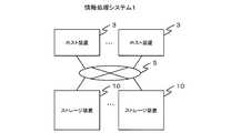
図1に第1実施形態として説明する情報処理システム1の概略的な構成を示している。同図に示すように、情報処理システム1は、一つ以上のホスト装置3(外部装置)、及び一つ以上のストレージ装置10を含んで構成されている。Hereinafter, embodiments will be described with reference to the drawings.
First Embodiment FIG. 1 shows a schematic configuration of an
ホスト装置3は、例えば銀行の自動預金預け払いサービスやインターネットのWebページ閲覧サービス等のサービスを提供するコンピュータである。ストレージ装置10は、ホスト3装置にて実行されるアプリケーションプログラム等にデータの記憶領域を提供する。 The
ホスト装置3とストレージ装置10とは、ストレージネットワーク5を介して通信可能に接続している。ストレージネットワーク5は、例えば、LAN(Local Area Network)、WAN(Wide Area Network)、SAN(Storage Area Network)、インターネット、公衆通信網、専用線などである。ストレージネットワーク5を介して行われる通信は、例えば、TCP/IP、iSCSI(internet Small Computer System Interface)、ファイバーチャネルプロトコル(Fibre Channel Protocol)、FICON(Fibre Connection)(登録商標)、ESCON(Enterprise System Connection) (登録商標)、ACONARC(Advanced Connection Architecture)(登録商標)、FIBARC(Fibre Connection Architecture)(登録商標)などのプロトコルに従って行われる。 The
ホスト装置3のハードウエアは、例えばパーソナルコンピュータ、メインフレーム(Mainframe)、オフィスコンピュータなどである。ホスト装置3は、ストレージ装置10が提供する上記記憶領域にアクセスするに際し、データI/O要求(データ書き込み要求、データ読み出し要求等)を含んだデータフレーム(以下、フレームと略記する。)をストレージ装置10に送信する。フレームは、例えばファイバーチャネルのフレーム(FCフレーム(FC: Fibre Channel))である。 The hardware of the
図2にホスト装置3として用いられる情報処理装置(コンピュータ)のハードウエアの一例を示している。同図に示すように、この情報処理装置は、CPU31、揮発性または不揮発性のメモリ32(RAMまたはROM)、記憶装置33(例えばHDD(Hard Disk Drive)、半導体記憶装置(SSD(Solid State Drive)))、キーボードやマウス等の入力装置34、液晶モニタやプリンタ等の出力装置35、及びNIC(Network Interface Card)やHBA(Host Bus Adapter)等の通信インタフェース(通信I/F36と表記する。)を備えている。 FIG. 2 shows an example of hardware of an information processing device (computer) used as the
図3にストレージ装置10のハードウエア構成の一例を示している。ストレージ装置10は例えばディスクアレイ装置である。同図に示すように、ストレージ装置10は、一つ以上のチャネル制御部11、一つ以上のプロセッサ部12(Micro Processor)、一つ以上のドライブ制御部13、キャッシュメモリ14(Cache Memory)、共有メモリ15(Shared Memory)、内部スイッチ16、記憶装置17、及び保守装置18(SVP: SerVice Processor)を備えている。チャネル制御部11、プロセッサ部12、ドライブ制御部13、キャッシュメモリ14、及び共有メモリ15は、内部スイッチ16を介して互いに通信可能に接続されている。 FIG. 3 shows an example of the hardware configuration of the
このうちチャネル制御部11は、ホスト装置3から送られてくるフレームを受信し、受信したフレームに含まれているデータI/O要求についての処理の応答(例えば読み出したデータ、読み出し完了報告、書き込み完了報告)を含むフレームをホスト装置3に送信する。 Among these, the
プロセッサ部12は、チャネル制御部11が受信したフレームに含まれている上記データI/O要求に応じてチャネル制御部11、ドライブ制御部13、及びキャッシュメモリ14の間で行われるデータ転送に関する処理を行う。プロセッサ部12は、キャッシュメモリ14を介して行われる、チャネル制御部11とドライブ制御部13との間のデータ(記憶装置17から読み出したデータ、記憶装置17に書き込むデータ)の引き渡しや、キャッシュメモリ14に格納されるデータのステージング(記憶装置17からのデータの読み出し)又はデステージング(キャッシュメモリ14のデータの記憶装置17への書き出し)などを行う。 The
キャッシュメモリ14は、例えば、高速アクセスが可能なRAM(Random Access Memory)を用いて構成されている。キャッシュメモリ14には、記憶装置17に書き込まれるデータ(以下、書き込みデータと称する。)や記憶装置17から読み出されたデータ(以下、読み出しデータと記載する。)等が格納される。 The
共有メモリ15には、ストレージ装置10の制御に用いられる各種の情報が格納される。 The shared
ドライブ制御部13は、記憶装置17からのデータの読み出しや記憶装置17へのデータの書き込みに際し記憶装置17と通信を行う。 The
内部スイッチ16は、例えば高速クロスバースイッチ(Cross Bar Switch)を用いて構成される。内部スイッチ16を介して行われる通信は、ファイバーチャネル、iSCSI、TCP/IP等のプロトコルに従って行われる。 The
記憶装置17は、物理的な記憶媒体である複数の物理ドライブ171を備えて構成されている。物理ドライブ171は、SAS(Serial Attached SCSI)、SATA(Serial ATA)、FC(Fibre Channel)、PATA(Parallel ATA)、SCSIなどの形式のハードディスクドライブ、半導体記憶装置(SSD)などのハードウエアを用いて構成されている。尚、記憶装置17は、ストレージ装置10と同一の筐体に収容されていてもよいし、ストレージ装置10とは別の筐体に収容されていてもよい。 The
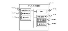
図4にチャネル制御部11のハードウエア構成を示している。同図に示すように、チャネル制御部11は、ホスト装置3と通信するための一つ以上のポート(通信ポート)を備えた外部通信インタフェース(以下、外部通信I/F111(第2データ転送装置)と表記する。)、メモリ113、及びプロセッサ部12と通信するためのポート(通信ポート)を有する内部通信インタフェース(以下、内部通信I/F114と表記する。)を備えている。 FIG. 4 shows a hardware configuration of the
外部通信I/F111は、ストレージネットワーク5における通信に用いられる通信規約(通信プロトコル)に従いストレージネットワーク5を介してホスト装置3と通信する。同図に示すように、外部通信I/F111は、CPU(Central Processing Unit)、MPU(Micro Processing Unit)、もしくはASIC(Application Specific Integrated Circuit)などの半導体装置(又は半導体集積回路)を用いて構成される制御装置(以下、第2制御装置1111と称する。)と、DMA(Direct Memory Access)(以下、第2DMA1112(第2データ転送装置)と称する。)とを備える。尚、第2DMA1112は、第2制御装置1111の内部に組み込まれていてもよいし、第2制御装置1111とは別体(別のパッケージ)であってもよい。 The external communication I /
第2制御装置1111は、ホスト装置3や内部通信I/F114と通信する。また第2制御装置1111は、第2DMA1112を制御して、メモリ113に格納されているデータをホスト装置3に転送する。また第2制御装置1111は、第2DMA1112を制御して、ホスト装置3から送られてくるデータをメモリ113に格納する。 The
内部通信I/F114は、内部スイッチ16を介して、プロセッサ部12、ドライブ制御部13、キャッシュメモリ14、及び共有メモリ15と通信する。同図に示すように、内部通信I/F114は、CPU、MPU、もしくはASICなどの半導体装置(又は半導体集積回路)を用いて構成される制御装置(以下、第1制御装置1141と称する。)と、DMA(以下、第1DMA1142(第1データ転送装置)と称する。)とを備える。尚、第1DMA1142は、第1制御装置1141の内部に組み込まれていてもよいし、第1制御装置1141とは別体(別のパッケージ)であってもよい。 The internal communication I /
第1制御装置1141は、第1DMA1142を制御して、メモリ113に格納されているデータをキャッシュメモリ14に転送する。また第1制御装置1141は、第1DMA1142を制御して、キャッシュメモリ14に格納されているデータをメモリ113に転送する。 The
メモリ113は、ROM(Read Only Memory)及びRAM(Random Access Memory)2を含む。メモリ113は、外部通信I/F111と内部通信I/F114との間、並びに内部通信I/F114とキャッシュメモリ14との間で行われるデータ転送に際してデータの一時的な格納領域(データバッファ)を提供する。メモリ113にはマイクロプログラムが格納されている。外部通信I/F111又は内部通信I/F114が、メモリ113からマイクロプログラムを読み出して実行することにより、チャネル制御部11が提供する各種の機能が実現される。 The
図5にプロセッサ部12のハードウエア構成を示している。プロセッサ部12は、一つ以上のマイクロプロセッサ(Micro Processor)(以下、MP122(転送パラメータ設定装置)と称する。)、及びローカルメモリ(Local Memory)(以下、LM123と称する。)を備えている。MP122は、CPU、MPU、ASIC等を用いて構成されている。LM123にはマイクロプログラムが格納されている。MP122が、LM123から上記マイクロプログラムを読み出して実行することにより、プロセッサ部12が提供する各種の機能が実現される。 FIG. 5 shows a hardware configuration of the
尚、MP122及びLM123は、多対一の関係(例えば複数MP122が共通のLM123を利用する場合)、多対多の関係(例えばMP122ごとに異なるLM123が設けられる場合)などストレージ装置10の種類に応じて様々な態様で設けられる。 Note that the
図6にドライブ制御部13のハードウエア構成を示している。ドライブ制御部13は、内部通信インタフェース(以下、内部通信I/F131と表記する。)、メモリ133、及びドライブインタフェース(以下、ドライブI/F134と表記する。)を備えている。 FIG. 6 shows a hardware configuration of the
内部通信I/F131は、CPU、MPU、ASIC等を用いて構成される演算制御装置と、DMAとを備える。尚、DMAは、演算制御装置の内部に組み込まれていてもよいし、演算制御装置とは別体(別のパッケージ)であってもよい。内部通信I/F131は、内部スイッチ16を介して、チャネル制御部11、プロセッサ部12、キャッシュメモリ14、及び共有メモリ15と通信する。 The internal communication I /
ドライブI/F134は、所定の通信方式に従って記憶装置17と通信する。 The drive I /
メモリ133は、ROM及びRAMを含む。メモリ133は、内部通信I/F131とドライブI/F134との間、並びに内部通信I/F131とキャッシュメモリ14との間で行われるデータ転送に際してデータの一時的な格納領域(データバッファ)を提供する。メモリ133にはマイクロプログラムが格納されている。内部通信I/F131又はドライブI/F134が、メモリ133からマイクロプログラムを読み出して実行することにより、ドライブ制御部13が提供する各種の機能が実現される。 The
図3に示す保守装置18は、ストレージ装置10の各構成要素の制御や状態監視を行う。保守装置18は、パーソナルコンピュータやオフィスコンピュータ等である。保守装置18は、内部スイッチ16又はLAN等の通信手段を介してチャネル制御部11、プロセッサ部12、ドライブ制御部13、キャッシュメモリ14、共有メモリ15、及び内部スイッチ16等のストレージ装置10の構成要素と随時通信を行い、各構成要素から稼働情報等を取得して管理装置7に提供する。また保守装置18は管理装置7から送られてくる制御情報や稼働情報に基づき、各構成要素の設定や制御、保守(ソフトウエアの導入や更新を含む)を行う。 The
管理装置7は、保守装置18とLAN等を介して通信可能に接続されるコンピュータである。管理装置7はストレージ装置10の制御や監視のためのGUI(Graphical User Interface)やCLI(Command Line Interface)等を用いたユーザインタフェースを備える。 The management device 7 is a computer that is communicably connected to the
図7は管理装置7として利用可能な情報処理装置(コンピュータ)のハードウエアの一例である。同図に示すように、この装置は、CPU71、揮発性または不揮発性のメモリ72(RAMまたはROM)、記憶装置73(例えばHDD(Hard Disk Drive)、半導体記憶装置(SSD(Solid State Drive)))、キーボードやマウス等の入力装置74、液晶モニタやプリンタ等の出力装置75、及び保守装置18と通信するための通信インタフェース(通信I/F76)を備えている。 FIG. 7 shows an example of hardware of an information processing apparatus (computer) that can be used as the management apparatus 7. As shown in the figure, this device includes a
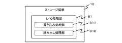
図8にストレージ装置10の基本的な機能を示している。同図に示すように、ストレージ装置10は、記憶装置17へのデータの書き込みに関する処理を行う書き込み処理部811、及び記憶装置17からのデータの読み出しに関する処理を行う読み出し処理部812からなるI/O処理部81を備える。 FIG. 8 shows the basic functions of the
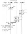
図9は、ストレージ装置10がホスト装置3からデータ書き込み要求を含んだフレームを受信した場合に、I/O処理部81の書き込み処理部811が行う基本的な処理(以下、書き込み処理S900と称する。)を説明するフローチャートである。以下、同図とともに書き込み処理S900について説明する。尚、以下の説明において、符号の前に付している「S」の文字はステップを意味する。 FIG. 9 illustrates basic processing (hereinafter referred to as write processing S900) performed by the
ホスト装置3から送信されてくるデータ書き込み要求のフレームは、ストレージ装置10のチャネル制御部11によって受信される(S911,S912)。チャネル制御部11はフレームを受信するとその旨をプロセッサ部12に通知する(S913)。 The data write request frame transmitted from the
プロセッサ部12は、チャネル制御部11から上記通知を受信すると(S921)、当該フレームのデータ書き込み要求に基づくドライブ書き込み要求を生成し、書き込みデータをキャッシュメモリ14に格納する。次にプロセッサ部12は、生成したドライブ書き込み要求をドライブ制御部13に送信する(S922,S923)。チャネル制御部11は、ホスト装置3に完了報告を送信し(S914)、ホスト装置3は完了報告を受信する(S915)。 When receiving the notification from the channel control unit 11 (S921), the
ドライブ制御部13は、ドライブ書き込み要求を受信すると書き込み処理待ちキューに登録する(S924)。ドライブ制御部13は、書き込み処理待ちキューからドライブ書き込み要求を随時読み出す(S925)。ドライブ制御部13は、読み出したドライブ書き込み要求に指定されている書き込みデータをキャッシュメモリ14から読み出し、読み出した書き込みデータを物理ドライブ171に書き込む(S926)。 When receiving the drive write request, the
次にドライブ制御部13は、ドライブ書き込み要求について書き込みデータの書き込みが完了した旨の報告(完了報告)をプロセッサ部12に送信し(S927)、プロセッサ部12は送られてきた完了報告を受信する(S928)。 Next, the
図10はストレージ装置10がホスト装置3からデータ読み出し要求を含んだフレームを受信した場合にストレージ装置10のI/O処理部81の読み出し処理部812によって行われるI/O処理(以下、読み出し処理S1000と称する。)を説明するフローチャートである。以下、同図とともに読み出し処理S1000について説明する。 FIG. 10 illustrates an I / O process (hereinafter referred to as a read process) performed by the
ホスト装置3から送信されてくるフレームは、ストレージ装置10のチャネル制御部11によって受信される(S1011,S1012)。チャネル制御部11は、ホスト装置3からフレームを受信すると、その旨をプロセッサ部12及びドライブ制御部13に通知する。 The frame transmitted from the
ドライブ制御部13は、チャネル制御部11から上記通知を受信すると(S1013)、当該フレームに含まれているデータ読み出し要求に指定されているデータ(例えばLBA(Logical Block Address)によって指定される)を、記憶装置17(物理ドライブ171)から読み出す(S1014)。尚、キャッシュメモリ14に読み出しデータが存在する場合(キャッシュヒットした場合)には、記憶装置17からの読み出し処理(S1015)は省略される。プロセッサ部12は、ドライブ制御部13によって読み出されたデータをキャッシュメモリ14に書き込む(S1015)。プロセッサ部12は、キャッシュメモリ14に書き込んだデータを通信I/Fに随時転送する(S1016)。 When the
チャネル制御部11は、プロセッサ部12から送られてくる読み出しデータをホスト装置3に順次送信する(S1017,S1018)。読み出しデータの送信が完了すると、チャネル制御部11はホスト装置3に完了報告を送信し(S1019)、ホスト装置3は送られてきた完了報告を受信する(S1020)。 The
ホスト装置3の通信I/F36が備える通信ポート(以下、ホストポートと称する。)には、ストレージネットワーク5に接続している機器を識別するための識別情報であるポートID(例えばWWN(World Wide Name))が付与されている。ポートIDは、通信I/F36が有する通信ポートのそれぞれに付与されている。従って、例えばストレージネットワーク5に接続するための通信ポートを複数備える通信I/F36は夫々の通信ポートに異なるポートIDが付与される。 A communication port (hereinafter referred to as a host port) included in the communication I /
一方、ストレージ装置10のチャネル制御部11がストレージネットワーク5に接続するために備える通信ポート(以下、ストレージポートと称する。)にもポートID(例えばWWNやMACアドレス)が付与されている。 On the other hand, a port ID (for example, WWN or MAC address) is also assigned to a communication port (hereinafter referred to as a storage port) provided for the
以下ホスト装置3の通信I/F36に付与されているポートIDのことをホストポートIDと、チャネル制御部11が備える通信ポートの夫々に付与されているポートIDのことをチャネルポートIDと称する。 Hereinafter, the port ID assigned to the communication I /
ストレージ装置10は、物理ドライブ171の記憶領域を予め定められた割当単位(以下、物理ページと称する。)で割り当てることにより構成される論理的な記憶領域である論理ユニット(LU:Logical Unit)を単位として、物理ドライブ171の記憶領域をホスト装置3に提供する。例えば論理ユニットは、ホスト装置3にインストールされているオペレーティングシステムにおいてデバイスファイル(Device File)やドライブレター(ドライブ名)に対応づけられる。論理ユニットの夫々には論理ユニットごとに固有の識別子である論理ユニット番号(LUN(Logical Unit Number))が付与される。ホスト装置3は、LUNにより論理ユニットを特定する。LUNは例えばホスト装置3からストレージ装置10に送信されるデータ入出力要求に設定される。 The
ストレージ装置10は、物理ドライブ171が提供する物理的な記憶領域(以下、物理記憶領域と称する)を、この物理記憶領域を用いて論理的に設定される記憶領域である論理デバイス(LDEV(Logical Device))を単位として認識している。各論理デバイスには、論理デバイスごとに固有の論理デバイス番号(LDEV番号)が識別子として付与されている。論理デバイスの記憶領域は、例えば複数のハードウエアをRAID(Redundant Arrays of Inexpensive (or Independent) Disks)方式(RAID0〜6の少なくともいずれか)で制御することによって構成されている。 The
図11は、ホスト装置3からストレージ装置10へのアクセス経路(パス)を説明する模式図である。同図に示すように、ホスト装置3からストレージ装置10へのアクセス経路は、ホストポートID(ホストポート1、ホストポート2、・・・)、ストレージポートID(ストレージポート1、ストレージポート2、・・・)、LUN(LUN1、LUN2、・・・)及びLDEV番号(LDEV1、LDEV2、・・・)の組み合わせによって特定することができる。 FIG. 11 is a schematic diagram for explaining an access route (path) from the
図12にストレージ装置10の記憶装置17にデータの書き込みを行おうとする際、ホスト装置3がストレージ装置10に送信するデータ書き込み要求1200のデータフォーマットの一例を示している。 FIG. 12 shows an example of a data format of a data write request 1200 transmitted from the
同図に示すように、データ書き込み要求1200には、I/Oコマンド1211、LUN1212、アドレス1213、送信元ポートID1214、及び書き込みデータ1215などの情報が含まれている。 As shown in the figure, the data write request 1200 includes information such as an I /
このうちI/Oコマンド1211には、ストレージ装置10にデータの書き込みを要求するコマンドが設定される。LUN1212には、データの書き込み先の論理ユニットのLUNが設定される。アドレス1213には、データの書き込み先となる記憶領域を指定するアドレスが設定される。送信元ポートID1214には、当該要求の送信元のホスト装置3の通信I/F36に付与されているホストポートIDが設定される。書き込みデータ1215には、当該要求により記憶装置17に書き込もうとする書き込みデータが設定される。 Of these, the I /
図13にストレージ装置10の記憶装置17からデータを読み出そうとする際、ホスト装置3がストレージ装置10に送信するデータ読み出し要求1300のデータフォーマットの一例を示している。 FIG. 13 shows an example of the data format of a data read request 1300 that the
同図に示すように、データ読み出し要求1300には、I/Oコマンド1311、LUN1312、アドレス1313、送信元ポートID1314、及びデータサイズ1315などの情報が含まれている。 As shown in the figure, the data read request 1300 includes information such as an I /
このうちI/Oコマンド1311には、ストレージ装置10にデータの読み出しを要求するコマンドが設定される。LUN1312には、データの読み出し先の論理ユニットのLUNが設定される。アドレス1313には、データの読み出し先となる記憶領域を指定するアドレスが設定される。送信元ポートID1314には、当該要求の送信元のホスト装置3の通信I/F36に付与されているホストポートIDが設定される。データサイズ1315には、当該要求によって記憶装置17から読み出そうとしているデータのデータサイズが設定される。 Of these, the I /
本実施形態におけるホスト装置3は、メインフレーム等の可変長形式でデータを管理する装置であり、ホスト装置3から送られてくるデータはCKD形式(CKD: Count Key Data architecture)のデータである。このため、ストレージ装置10がホスト装置3からデータ書き込み要求1200を受信した場合にキャッシュメモリ14に書き込まれる書き込みデータ、並びに、ストレージ装置10がホスト装置3からデータ読み出し要求1250を受信した場合に記憶装置17から読み出されてキャッシュメモリ14に書き込まれる読み出しデータは、いずれもCKD形式のデータとして管理される。 The
図14にCKD形式のデータ(以下、CKD形式データ1400と称する。)のデータフォーマットを示している。同図に示すように、CKD形式データ1400には、C部1411(Count部)(第1データ部)、K部1412(Key部)(第2データ部)、及びD部1413(Data部)(第2データ部)、の3つの領域(以下、データ部とも称する。)が含まれている。尚、1つのCKD形式データ1400(1つのC部1411、1つのK部1412、1つのD部1413からなる1セットのデータ(転送対象データ))は、例えば、記憶装置17の記憶領域の管理単位であるデータブロックごとに生成される。 FIG. 14 shows a data format of CKD format data (hereinafter referred to as CKD format data 1400). As shown in the figure, CKD format data 1400 includes a C section 1411 (Count section) (first data section), a K section 1412 (Key section) (second data section), and a D section 1413 (Data section). (Second data portion), three regions (hereinafter also referred to as data portions). One CKD format data 1400 (one set of data (transfer target data) including one
CKD形式データ1400の3つのデータ部のうち、C部1411には、例えば、当該データの格納先であるデータブロックのブロック番号、K部1412のデータ長、D部1413のデータ長などの制御情報が格納される。K部1412には、検索キー情報などのホスト装置3にて動作するアプリケーションに関連する情報が格納される。D部1413には、書き込みデータ又は読み出しデータの実体が格納される。尚、C部1411のデータ長は固定(例えば8Byte)であり、K部1412及びD部1413のデータ長は可変である。 Among the three data parts of the CKD format data 1400, the
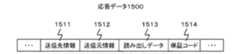
図15はデータ読み出し要求1300に応じてストレージ装置10が読み出しデータをホスト装置3に送信する際に送信される応答データ1500のデータフォーマットの一例である。同図に示すように、応答データ1500には、送信先情報1511、送信元情報1512、読み出しデータ1513、及び保証コード1514などの情報が含まれている。 FIG. 15 shows an example of the data format of response data 1500 transmitted when the
このうち送信先情報1511には、当該応答データ1500の送信先のホスト装置3を特定する情報(例えばホスト装置3の識別子やホスト装置3のネットワークアドレス等)が設定される。送信元情報1512には、当該応答データ1500の送信元のストレージ装置10を特定する情報(例えばストレージ装置10の識別子やストレージ装置10のネットワークアドレス等)が設定される。読み出しデータ1513には、記憶装置17から読み出した読み出しデータが設定される。保証コード1514には、ストレージ装置10が、読み出しデータ1513に設定される読み出しデータについて計算した保証コード(例えばLRC(Longitudinal Redundancy Check)、CRC(Cyclic Redundancy Check)等)が設定される。 Among these, information (for example, an identifier of the
図16は、ストレージ装置10にて行われるデータ転送に関する動作を模式的に説明した図であり、チャネル制御部11が、キャッシュメモリ14に格納されているデータを読み出してホスト装置3に送信する際に行われる動作を説明した図である。また図17は、図16に示す動作をより詳細に説明したフローチャートである。 FIG. 16 is a diagram schematically illustrating operations related to data transfer performed in the
尚、図16、図17に示す動作は、例えば、ホスト装置3から送られてくるデータ読み出し要求1300に応じて行われる動作であり、例えば、図10のS1016〜S1017の処理に際して行われる動作である。以下、これらの図とともに説明する。 Note that the operations shown in FIGS. 16 and 17 are, for example, operations performed in response to a data read request 1300 sent from the
まずプロセッサ部12のMP122は、第1DMA1142にデータ転送パラメータ(以下、第1DMA用転送パラメータ1800と称する。)を設定する(S1611,S1711)。この第1DMA用転送パラメータ1800によるデータ転送の対象となるデータは、例えばドライブ制御部13によってキャッシュメモリ14にステージングされた読み出しデータである。 First, the
ホスト装置3から送られてくるデータ読み出し要求1300に応じて上記動作が行われる場合、第1DMA用転送パラメータ1800の設定は、そのデータ読み出し要求1300について必要な回数だけ繰り返し行われる。必要な回数は、例えば、CCW(Channel Command Word)チェインを構成しているCCWの数に対応した回数である。 When the above operation is performed in response to a data read request 1300 sent from the
第1DMA1142に対する第1DMA用転送パラメータ1800は、このようにMP122が第1DMA1142に対して直接設定するようにしてもよいし、MP122から第1制御装置1141に第1DMA用転送パラメータ1800を送信し、これを受信した第1制御装置1141が第1DMA1142に対して第1DMA用転送パラメータ1800を設定するように、つまりMP122が、第1制御装置1141を介して第1DMA1142に第1DMA用転送パラメータ1800を設定するようにしてもよい。 The first DMA transfer parameter 1800 for the
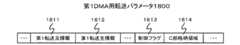
図18に第1DMA用転送パラメータ1800のデータ構成を示している。同図に示すように、第1DMA用転送パラメータ1800は、第1転送元情報1811、及び第1転送先情報1812を含む。 FIG. 18 shows the data structure of the first DMA transfer parameter 1800. As shown in the figure, the first DMA transfer parameter 1800 includes first transfer
このうち第1転送元情報1811には、第1DMA1142によるデータ転送についてのデータの転送元を示す情報が設定される。第1転送先情報1812には、第1DMA1142によるデータ転送についてのデータの転送先を示す情報が設定される。 Among these, in the first
例えば、第1DMA1142によるデータ転送の転送方向が、キャッシュメモリ14からメモリ113である場合、第1転送元情報1811にはキャッシュメモリ14のアドレスが、第1転送先情報1812にはメモリ113のアドレスが、夫々設定される。また第1DMA1142によるデータ転送の転送方向が、メモリ113からキャッシュメモリ14である場合、第1転送元情報1811にはメモリ113のアドレスが、第1転送先情報1812にはキャッシュメモリ14のアドレスが、夫々設定される。 For example, when the transfer direction of data transfer by the
再び図16及び図17に戻って説明する。S1611(又はS1711)において、第1DMA1142の第1DMA用転送パラメータ1800が設定されると、第1DMA1142は、設定された第1DMA用転送パラメータ1800に従いデータ転送(キャッシュメモリ14(転送元装置)に格納されているデータのメモリ113(転送先装置)へのデータ転送)を開始する(S1612,S1712)。 Returning to FIG. 16 and FIG. When the first DMA transfer parameter 1800 of the
データ転送の実行中、内部通信I/F114は、第1DMA1142によるデータ転送が完了したか否かを監視している(S1713)。データ転送が完了すると(S1713:YES)、内部通信I/F114は、終了ステータス(以下、第1終了ステータスと称する。)をMP122のLM123に書き込む(S1613,S1714)。これによりMP122は第1DMA1142によるデータ転送が終了したことを知ることができる。 During execution of data transfer, the internal communication I /
プロセッサ部12は、LM123に第1終了ステータスが書き込まれたことを検知すると、続いて第2DMA1112に転送パラメータ(以下、第2DMA用転送パラメータ1900と称する。)を設定する(S1614,S1715)。 When detecting that the first end status is written in the
図19に第2DMA用転送パラメータ1900のデータ構成を示している。同図に示すように、第2DMA用転送パラメータ1900は、第2転送元情報1911及び第2転送先情報1912を含む。第2転送元情報1911には、第2DMA1112によるデータ転送についてのデータの転送元を示す情報が設定される。第2転送先情報1912には、第2DMA1112によるデータ転送についてのデータの転送先を示す情報が設定される。 FIG. 19 shows the data configuration of the second DMA transfer parameter 1900. As shown in the figure, the second DMA transfer parameter 1900 includes second transfer
例えば、第2DMA1112によるデータ転送の転送方向が、メモリ113からホスト装置3である場合、第2転送元情報1911にはメモリ113のアドレスが、第2転送先情報1912にはホスト装置3側の転送先のデータの格納位置を示す情報が、夫々設定される。また例えば第2DMA1112によるデータ転送の転送方向が、ホスト装置3からメモリ113である場合、第2転送元情報1911にはホスト装置3の転送元のデータの格納位置を示す情報が、第2転送先情報1912にはメモリ113のアドレスが、夫々設定される。 For example, when the transfer direction of the data transfer by the
尚、第2DMA1112に対する第2DMA用転送パラメータ1900の設定は、このように内部通信I/F114が第2DMA1112に対して直接行うようにしてもよいし、第2DMA1112から第2制御装置1111に第2DMA用転送パラメータ1900を送信し、これを受信した第2制御装置1111が第2DMA1112に対して第2DMA用転送パラメータ1900を設定するように、つまり第1制御装置1111を介して間接的に第2DMA1112に第2DMA用転送パラメータ1900を設定するようにしてもよい。 Note that the setting of the second DMA transfer parameter 1900 for the
第2DMA用転送パラメータ1900が設定されると、第2DMA1112は、第2DMA用転送パラメータ1900に従ってデータ転送(メモリ113に格納されているデータのホスト装置3へのデータ転送)を開始する(S1615,S1716)。 When the second DMA transfer parameter 1900 is set, the
データ転送の実行中、外部通信I/F111は、第2DMA1112によるデータ転送が完了したか否かを監視している(S1717)。データ転送が完了すると(S1717:YES)、外部通信I/F111は、その終了ステータス(以下、第2終了ステータスと称する。)をMP122のLM123に書き込む(S1616,S1718)。 During the execution of data transfer, the external communication I /
図20は、図16及び図17とともに説明した動作に関する内部通信I/F114の機能を模式的に説明した図である。同図において「S」の文字が付されている符号はいずれも図16又は図17に示した符号と対応している。 FIG. 20 is a diagram schematically illustrating the function of the internal communication I /
同図に示すように、内部通信I/F114は、転送パラメータI/F201、転送パラメータ処理部202、及びデータ転送部203の各機能を有する。また転送パラメータ処理部202は、少なくともプロセッサ部12が備えるMP122の数に対応する数以上のバッファ2021(同図では「BF」と表記している。)を備える。 As shown in the figure, the internal communication I /
同図に示すように、データ転送部203は、第1通信I/F2031、メモリI/F2032、及び第2通信I/F2033を備える。尚、これらの機能は、内部通信I/F114が備えるハードウエアによって、もしくは内部通信I/F114の第1制御装置1141が、内部通信I/F114やメモリ113に保持されているプログラムを読み出して実行することにより実現される。 As shown in the figure, the
同図において、転送パラメータI/F201は、プロセッサ部12が備える一つ以上のMP122のうちのいずれかのMP122から送られてくる第1DMA用転送パラメータ1800を受信し、受信した第1DMA用転送パラメータ1800を、そのMP122に対応するバッファ2021に格納する(S1611,S1711)。 In the figure, a transfer parameter I /
第1DMA用転送パラメータ1800がバッファ2021に格納されると、データ転送部203は、第1DMA用転送パラメータ1800に基づき、メモリI/F2032及び第2通信I/F2033によりデータ転送(キャッシュメモリ14に格納されているデータのメモリ113へのデータ転送)を開始する(S1612,S1712)。 When the first DMA transfer parameter 1800 is stored in the
転送パラメータ処理部202は、第1DMA1142によるデータ転送が完了すると(S1713:YES)、第1終了ステータスをMP122のLM123に書き込む(S1613,S1714)。尚、プロセッサ部12が複数のMP122を備えている場合、転送パラメータ処理部202は、S1611(又はS1711)にて第1DMA用転送パラメータ1800の設定を行ったMP122に割り当てられているLM123の記憶領域に第1終了ステータスを書き込む。 When the data transfer by the
次にプロセッサ部12が、第2DMA用転送パラメータ1900を外部通信I/F111の第2DMA1112に設定して第2DMA1112を起動する(S1614,S1715)。第2DMA1112は、第2DMA用転送パラメータ1900に基づきデータ転送(メモリ113に格納されているデータのホスト装置3へのデータ転送)を開始する(S1615,S1716)。 Next, the
第2DMA1112によるデータ転送が完了すると(S1717:YES)、外部通信I/F111は、第2終了ステータスをMP122のLM123に書き込む(S1616,S1718)。尚、プロセッサ部12が複数のMP122を備えている場合、外部通信I/F111は、S1611(S1711)にて第1DMA用転送パラメータ1800の設定を行ったMP122に割り当てられているLM123の記憶領域に第2終了ステータスを書き込む。 When the data transfer by the
図21に第1DMA用転送パラメータ1800(第2DMA用転送パラメータ1900も同様)のデータ構成例(以下、データ2100と称する。)を示す。同図に示すように、データ2100には、転送バイト数2111、転送元アドレス2112、転送先アドレス2113、転送方向2114、誤り検出符号2115、チェインフラグ2116などの情報が含まれている。データ2100は、例えば、10ワード(=4バイト)のデータ長を有する。尚、データ2100のデータ長は必ずしもこの値に限定されない。 FIG. 21 shows a data configuration example (hereinafter referred to as data 2100) of the first DMA transfer parameter 1800 (the same applies to the second DMA transfer parameter 1900). As shown in the figure, the
転送バイト数2111には、転送対象となるデータのデータ長が設定される。転送元アドレス2112には、第1転送元情報1811や第2転送元情報1911が設定される。転送先アドレス2113には、第1転送先情報1812や第2転送先情報1912が設定される。 In the
転送方向2114には、そのデータ転送の方向を示す情報、例えば、キャッシュメモリ14からメモリ113へのデータ転送であるのか、メモリ113からキャッシュメモリ14へのデータ転送であるのかを示す情報が設定される。 In the
誤り検出符号2115には、転送対象となるデータの誤り検出符号(例えばCRC(Cyclic Redundancy Check)符号やLRC(Longitudinal Redundancy Check)符号)が設定される。誤り検出符号によって誤りが検出された場合、チャネル制御部11は、例えばデータ転送を中止して保守装置18にエラー情報を出力する。チェインフラグ2116には、例えば、CCWチェインにおける後続のCCWの存在有無を示す情報が設定される。 In the
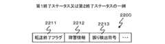
図22に第1終了ステータス又は第2終了ステータスの一例(以下、データ2200と称する。)を示している。同図に示すように、このデータ2200には、転送終了フラグ2211、障害情報2212、誤り検出符号2213などの情報が含まれている。 FIG. 22 shows an example of the first end status or the second end status (hereinafter referred to as data 2200). As shown in the figure, the
転送終了フラグ2211には、データ転送が終了したか否かを示す値が設定される。障害情報2212には、データ転送に際し何等かの障害が発生した場合に障害の内容を示す情報が設定される。MP122は、障害情報1812を参照することによりデータ転送時の障害の有無を検出する。誤り検出符号2213には、例えば、図21における誤り検出符号2115の内容がそのまま設定される。MP122は、誤り検出符号2213の内容に基づきデータ転送時のエラーの有無を検出する。 The
前述したように、ストレージ装置10がホスト装置3からデータ読み出し要求1250を受信した場合に記憶装置17から読み出されてキャッシュメモリ14に書き込まれる読み出しデータは、C部1411、K部1412、及びD部1413を含むCKD形式データ1400として管理されている。このため、第1DMA1142によって行われる、キャッシュメモリ14からメモリ113へのデータ転送に際して行われる一連の処理(図16のS1611〜S1613の処理又は図17のS1711〜S1714の処理)は、転送されるデータがCKD形式データ1400であることを前提として行われる。 As described above, when the
そして上記一連の処理に際し、MP122は、1つのCKD形式データ1400についてのキャッシュメモリ14からメモリ113へのデータ転送に際し、C部1411を転送するための第1DMA用転送パラメータ1800は生成せず、K部1412を転送するための第1DMA用転送パラメータ1800と、D部1413を転送するための第1DMA用転送パラメータ1800のみを生成する。 In the series of processes, the
図23は、上記一連の処理を模式的に説明した図であり、図24は上記一連の処理をより詳細に説明したフローチャートである。以下、これらの図とともに説明する。 FIG. 23 is a diagram schematically illustrating the series of processes, and FIG. 24 is a flowchart illustrating the series of processes in more detail. Hereinafter, it demonstrates with these figures.
まずプロセッサ部12のMP122は、キャッシュメモリ14に格納されているCKD形式データ1400のC部1411をLM123に読み出す(S2310,S2410)。 First, the
次にMP122は、第1DMA1142に、K部1412をキャッシュメモリ14からメモリ113に転送するための第1DMA用転送パラメータ1800を設定する(S2311,S2411)。尚、MP122は、キャッシュメモリ14からLM123に読み出したC部1411に含まれているK部1412に関する情報(K部1412のデータ長等)に基づき第1転送元情報1811及び第1転送先情報1812の内容を設定する。 Next, the
図25にこの際にMP122が生成する第1DMA用転送パラメータ1800のデータ構成を示している。同図に示すように、この第1DMA用転送パラメータ1800には、前述した第1転送元情報1811及び第1転送先情報1812に加えて、制御フラグ1813及びC部格納領域1814が含まれている。 FIG. 25 shows the data structure of the first DMA transfer parameter 1800 generated by the
このうち制御フラグ1813には、当該第1DMA用転送パラメータ1800のC部格納領域1814にC部1411が設定されているか否かを示す情報が設定される。具体的には、C部格納領域1814にC部1411のデータが格納されている場合は制御フラグ1813に「1」が、格納されていない場合は制御フラグ1813に「0」が設定される。 Among these, the
MP122は、K部1412の第1DMA用転送パラメータ1800の生成に際し、キャッシュメモリ14からLM123に読み出したC部1411をそのままC部格納領域1814に格納し、制御フラグ1813に「1」を設定する。
つまりMP122は、C部1411の第1DMA用転送パラメータ1800を生成する代わりに、K部1412の第1DMA用転送パラメータ1800を第1DMA1142に設定することにより
C部1411(C部1411の実体)を第1DMA1142に供給する。When generating the first DMA transfer parameter 1800 of the
In other words, the
以上のようにしてK部1412の第1DMA用転送パラメータ1800が第1DMA1142に設定されると、次に第1DMA1142は、設定された第1DMA用転送パラメータ1800のC部格納領域1814に格納されているC部1411のデータをメモリ113に格納する(S2312,S2412)。またこのとき第1DMA1142は、C部1411のデータについて保証コードを算出し、算出した値(CKD形式データ1400の保証コードのC部1411までの途中計算値)を保持する(S2413)。 When the first DMA transfer parameter 1800 of the
次に第1DMA1142は、設定された第1DMA用転送パラメータ1800に従い、K部1412のデータのデータ転送(キャッシュメモリ14に格納されているK部1412のメモリ113へのデータ転送)を行う(S2313,S2414)。またこのとき、第1DMA1142は、S2413にて保持しておいた保証コードとK部1412とに基づき、(S2413にて保持しておいた保証コードを引き継いで)保証コードを算出し、算出した値(CKD形式データ1400の保証コードのK部1412までの途中計算値)を保持する(S2415)。 Next, the
データ転送が完了すると、第1DMA1142は、K部1412のデータ転送についての第1終了ステータスをMP122のLM123に書き込む(S2314,S2416)。尚、MP122は、K部1412のデータ転送についての第1終了ステータスがLM123に書き込まれたことをもって、C部1411及びK部1412のデータ転送が完了したことを知ることができる。 When the data transfer is completed, the
LM123にK部1412のデータ転送についての第1終了ステータスが書き込まれたことを検知すると、次にMP122は、D部1413をキャッシュメモリ14からメモリ113に転送するための第1DMA用転送パラメータ1800を第1DMA1142に設定する(S2315,S2417)。尚、MP122は、キャッシュメモリ14からLM123に読み出したC部1411に含まれているD部1413に関する情報(D部1413のデータ長等)に基づき、第1転送元情報1811及び第1転送先情報1812の内容を設定する。 When the
ここでK部1412の第1DMA用転送パラメータ1800の場合とは異なり、D部1413の第1DMA用転送パラメータ1800の制御フラグ1813には「0」が設定される(D部1413の第1DMA用転送パラメータ1800のC部格納領域1814は利用しない)。 Here, unlike the case of the first DMA transfer parameter 1800 of the
D部1413の第1DMA用転送パラメータ1800が設定されると、次に第1DMA1142は、第1DMA用転送パラメータ1800に従い、D部1413のデータ転送(キャッシュメモリ14に格納されているデータのメモリ113へのデータ転送)を行う(S2316,S2418)。またこのとき、第1DMA1142は、S2415にて保持しておいた保証コードとD部1413のデータとに基づき、(S2415にて保持しておいた保証コードを引き継いで)保証コードを算出する(S2319)。 When the first DMA transfer parameter 1800 of the
データ転送が完了すると、第1DMA1142は、算出した値をCKD形式データ1400全体の保証コードとしてメモリ113の所定位置に格納する(S2317,S2420)。このように、第1DMA1142は、保証コードの算出順序(C部1411の保証コードを求めた後、K部1412の保証コードを求め、その後にD部1413の保証コードを算出する)を維持しつつメモリ113にデータを格納するので、正しい保証コードをホスト装置3に提供することができる。尚、メモリ113に格納された保証コードは、図15に示した応答データ1500の保証コード1514の領域に格納されて読み出しデータ1513とともにホスト装置3に送信される。 When the data transfer is completed, the
次に第1DMA1142は、D部1413のデータ転送についての第2終了ステータスをMP122のLM123に書き込む(S2318,S2421)。尚、MP122は、D部1413のデータ転送についての第2終了ステータスがLM123に書き込まれたことをもって、CKD形式データ1400(C部1411、K部1412、D部1413の全体)についてのデータ転送が完了したことを知ることができる。 Next, the
図26はCKD形式データ1400のメモリ113への格納状態の一例である。尚、S2313(又はS2414)にて転送されるK部1412のデータを、S2312(又はS2412)にて既にメモリ113に格納済のC部1411の格納域に連続してメモリ113に格納する場合には、C部1411の格納域の先頭アドレスからC部1411のデータ長分だけずらした位置を先頭アドレスとしてK部1412を格納すればよい。 FIG. 26 shows an example of the storage state of the CKD format data 1400 in the
以上に説明したように、MP122は、CKD形式データ1400についてのキャッシュメモリ14からメモリ113へのデータ転送に際し、C部1411を転送するための第1DMA用転送パラメータ1800については生成せず、C部1411のデータを含んだK部1412を転送するための第1DMA用転送パラメータ1800と、D部1413を転送するための第1DMA用転送パラメータ1800を生成して第1DMA1142に設定し、第1DMA1142が、設定された第1DMA用転送パラメータ1800に含まれているC部1411を取り出してメモリ113に格納する。 As described above, the
これによれば、MP122がC部1411を転送するための第1DMA用転送パラメータ1800は生成しない分、転送パラメータの設定回数が減り、CKD形式データ1400全体のC部1411を転送するための第1DMA用転送パラメータ1800の生成や設定に要する負荷が軽減される。またK部1412の第1DMA用転送パラメータ1800によってC部1411のデータ転送も行われ、第1DMA1142のデータ転送機能を利用したデータ転送はK部1412とD部1413のデータ転送のみとなり、第1DMA1142によるデータ転送回数が減る分、第1DMA1142の負荷が軽減され、CKD形式データ1400全体のデータ転送に要する時間が短縮される。また、K部1412の第1DMA用転送パラメータ1800(C部1411)を保証コードの計算対象として動作する第1DMA1142を実装したことで、パラメータ内のデータと後続のデータとに連続した保証コードを生成可能となり、正しい保証コードをホスト装置3に提供することができる。 According to this, since the first DMA transfer parameter 1800 for transferring the
以上によれば、データ転送を起動する側(プロセッサ部12)と起動される側(第1DMA1142)との通信距離が長い場合でも、キャッシュメモリ14に格納されているデータのホスト装置3へのデータ転送を高速に行うことができ、ストレージ装置10のホスト装置3に対するレスポンス性能やスループットを向上させることができる。 According to the above, even when the communication distance between the data transfer activation side (processor unit 12) and the activation side (first DMA 1142) is long, the data stored in the
以上、本発明の好適な実施例を説明したが、これらは本発明の説明のための例示であって、本発明の範囲を実施例にのみ限定する趣旨ではない。本発明は、他の種々の形態でも実施することができる。 As mentioned above, although the suitable Example of this invention was described, these are the illustrations for description of this invention, Comprising: It is not the meaning which limits the scope of the present invention only to an Example. The present invention can be implemented in various other forms.
Claims (12)
Translated fromJapanese前記第1データ転送装置に転送パラメータを設定する転送パラメータ設定装置と
を備えるデータ転送システムであって、
前記転送パラメータ設定装置は、
1つ以上の第2データ部と当該第2データ部の前記転送パラメータの設定に際して用いられる情報を含んだ第1データ部とを含む転送対象データを前記転送元装置から前記転送先装置に転送するに際し、
前記転送元装置から前記第1データ部を取得し、
取得した前記第1データ部に基づき、前記第1データ部を付帯させた、前記第2データ部を前記転送元装置から前記転送先装置に転送するための転送パラメータを前記第1データ転送装置に設定し、
前記第1データ転送装置は、前記転送パラメータに付帯する前記第1データ部を前記転送先装置に格納し、前記転送パラメータに従い前記第2データ部を前記転送元装置から前記転送先装置に転送することにより、前記転送対象データを前記転送元装置から前記転送先装置に転送する
データ転送システム。A first data transfer device communicably connected to each of the transfer source device and the transfer destination device;
A data transfer system comprising: a transfer parameter setting device that sets a transfer parameter in the first data transfer device,
The transfer parameter setting device includes:
Transfer target data including one or more second data portions and a first data portion including information used when setting the transfer parameters of the second data portion from the transfer source device to the transfer destination device. On the occasion
Obtaining the first data portion from the transfer source device;
Based on the acquired first data part, transfer parameters for transferring the second data part from the transfer source apparatus to the transfer destination apparatus are added to the first data transfer apparatus. Set,
The first data transfer device stores the first data portion attached to the transfer parameter in the transfer destination device, and transfers the second data portion from the transfer source device to the transfer destination device according to the transfer parameter. Accordingly, the data transfer system transfers the transfer target data from the transfer source device to the transfer destination device.
前記第1データ転送装置は、
前記第1データ部について保証コードを算出し、
前記第1データ部について算出された前記保証コードを引き継いで前記第2データ部について保証コードを算出し、
算出した前記保証コードを、前記転送先装置に格納される前記第1データ部及び前記第2データ部に付帯させ、
当該データ転送システムは、
ホスト装置と通信するチャネル制御部と、
記憶装置と通信するドライブ制御部と、
キャッシュメモリと、
前記チャネル制御部、前記ドライブ制御部、及び前記キャッシュメモリの間のデータ転送を行うプロセッサ部と、
前記チャネル制御部及び前記プロセッサ部を通信可能に接続する内部スイッチと、
を備え、
前記転送先装置は、前記チャネル制御部が備えるメモリであり、
前記転送元装置は、前記キャッシュメモリであり、
前記転送パラメータ設定装置は、前記プロセッサ部が備えるマイクロプロセッサであり、
前記転送対象データは、前記第1データ部としてC部を、前記第2データ部としてK部及びD部を含むCKD形式(Count Key Data architecture)のデータであり、
前記C部は、前記第2データ部の前記転送パラメータの設定に際して用いられる情報として、前記K部のデータ長及び前記D部のデータ長を含み、
当該データ転送システムは、前記ホスト装置と、前記チャネル制御部が備える前記メモリと、前記第1データ転送装置とに通信可能に接続され、前記転送パラメータ設定装置による転送パラメータの設定を受け付け、受け付けた前記転送パラメータに従い前記メモリに格納されている前記転送対象データを前記ホスト装置に転送する、第2データ転送装置をさらに備え、
前記プロセッサ部は、メモリと複数の前記マイクロプロセッサとを備え、
前記第1データ転送装置は、前記データ転送の終了後、前記転送パラメータを設定した前記マイクロプロセッサに割り当てられている前記メモリの記憶領域に前記データ転送についての第1終了ステータスを書き込み、
前記第2データ転送装置は、前記データ転送の終了後、前記転送パラメータを設定した前記マイクロプロセッサに割り当てられている前記メモリの記憶領域に前記データ転送についての第2終了ステータスを書き込み、
前記第1データ転送装置は、前記転送パラメータに従い前記データ転送を行う第1DMA(Direct Memory Access)を備え、
前記第2データ転送装置は、前記転送パラメータに従い前記データ転送を行う第2DMAを備える
データ転送システム。The data transfer system according to claim 1,
The first data transfer device includes:
Calculating a guarantee code for the first data portion;
Taking over the guarantee code calculated for the first data portion to calculate a guarantee code for the second data portion;
The calculated guarantee code is attached to the first data part and the second data part stored in the transfer destination device,
The data transfer system
A channel controller that communicates with the host device;
A drive controller that communicates with the storage device;
Cache memory,
A processor that performs data transfer between the channel controller, the drive controller, and the cache memory;
An internal switch for communicably connecting the channel control unit and the processor unit;
With
The transfer destination device is a memory provided in the channel control unit,
The transfer source device is the cache memory;
The transfer parameter setting device is a microprocessor included in the processor unit,
The transfer target data is data in CKD format (Count Key Data architecture) including a C part as the first data part and a K part and a D part as the second data part,
The C part includes the data length of the K part and the data length of the D part as information used when setting the transfer parameter of the second data part,
The data transfer system is communicably connected to the host device, the memory included in the channel control unit, and the first data transfer device, and receives and accepts transfer parameter settings by the transfer parameter setting device. A second data transfer device for transferring the transfer target data stored in the memory to the host device according to the transfer parameter;
The processor unit includes a memory and a plurality of the microprocessors.
The first data transfer device writes a first end status for the data transfer in a storage area of the memory allocated to the microprocessor that has set the transfer parameter after the data transfer is completed,
The second data transfer device writes a second end status for the data transfer in a storage area of the memory assigned to the microprocessor that has set the transfer parameter after the end of the data transfer,
The first data transfer device includes a first DMA (Direct Memory Access) that performs the data transfer according to the transfer parameter,
The second data transfer device includes a second DMA that performs the data transfer according to the transfer parameter.
前記第1データ転送装置は、
前記第1データ部について保証コードを算出し、
前記第1データ部について算出された前記保証コードを引き継いで前記第2データ部について保証コードを算出し、
算出した前記保証コードを、前記転送先装置に格納される前記第1データ部及び前記第2データ部に付帯させる
データ転送システム。The data transfer system according to claim 1,
The first data transfer device includes:
Calculating a guarantee code for the first data portion;
Taking over the guarantee code calculated for the first data portion to calculate a guarantee code for the second data portion;
A data transfer system for attaching the calculated guarantee code to the first data part and the second data part stored in the transfer destination device.
ホスト装置と通信するチャネル制御部と、
記憶装置と通信するドライブ制御部と、
キャッシュメモリと、
前記チャネル制御部、前記ドライブ制御部、及び前記キャッシュメモリの間のデータ転送を行うプロセッサ部と、
前記チャネル制御部及び前記プロセッサ部を通信可能に接続する内部スイッチと、
を備え、
前記転送先装置は、前記チャネル制御部が備えるメモリであり、
前記転送元装置は、前記キャッシュメモリであり、
前記転送パラメータ設定装置は、前記プロセッサ部が備えるマイクロプロセッサである
データ転送システム。The data transfer system according to claim 1,
A channel controller that communicates with the host device;
A drive controller that communicates with the storage device;
Cache memory,
A processor that performs data transfer between the channel controller, the drive controller, and the cache memory;
An internal switch for communicably connecting the channel control unit and the processor unit;
With
The transfer destination device is a memory provided in the channel control unit,
The transfer source device is the cache memory;
The data transfer system, wherein the transfer parameter setting device is a microprocessor included in the processor unit.
前記転送対象データは、前記第1データ部としてC部を、前記第2データ部としてK部及びD部を含むCKD形式(Count Key Data architecture)のデータであり、
前記C部は、前記第2データ部の前記転送パラメータの設定に際して用いられる情報として、前記K部のデータ長及び前記D部のデータ長を含む
データ転送システム。The data transfer system according to claim 4, wherein
The transfer target data is data in CKD format (Count Key Data architecture) including a C part as the first data part and a K part and a D part as the second data part,
The C section includes a data length of the K section and a data length of the D section as information used when setting the transfer parameter of the second data section.
前記ホスト装置と、前記チャネル制御部が備える前記メモリと、前記第1データ転送装置とに通信可能に接続され、前記転送パラメータ設定装置による転送パラメータの設定を受け付け、受け付けた前記転送パラメータに従い前記メモリに格納されている前記転送対象データを前記ホスト装置に転送する、第2データ転送装置をさらに備える
データ転送システム。The data transfer system according to claim 4, wherein
The host device, the memory included in the channel control unit, and the first data transfer device are communicably connected, accept transfer parameter settings by the transfer parameter setting device, and the memory according to the accepted transfer parameters A data transfer system further comprising a second data transfer device that transfers the transfer target data stored in the host device to the host device.
前記プロセッサ部は、メモリと複数の前記マイクロプロセッサとを備え、
前記第1データ転送装置は、前記データ転送の終了後、前記転送パラメータを設定した前記マイクロプロセッサに割り当てられている前記メモリの記憶領域に前記データ転送についての第1終了ステータスを書き込み、
前記第2データ転送装置は、前記データ転送の終了後、前記転送パラメータを設定した前記マイクロプロセッサに割り当てられている前記メモリの記憶領域に前記データ転送についての第2終了ステータスを書き込む
データ転送システム。The data transfer system according to claim 6, wherein
The processor unit includes a memory and a plurality of the microprocessors.
The first data transfer device writes a first end status for the data transfer in a storage area of the memory allocated to the microprocessor that has set the transfer parameter after the data transfer is completed,
The second data transfer device writes a second end status for the data transfer in a storage area of the memory allocated to the microprocessor in which the transfer parameter is set after the data transfer is completed.
前記第1データ転送装置は、前記転送パラメータに従い前記データ転送を行う第1DMA(Direct Memory Access)を備え、
前記第2データ転送装置は、前記転送パラメータに従い前記データ転送を行う第2DMAを備える
データ転送システム。The data transfer system according to claim 6, wherein
The first data transfer device includes a first DMA (Direct Memory Access) that performs the data transfer according to the transfer parameter,
The second data transfer device includes a second DMA that performs the data transfer according to the transfer parameter.
前記第1データ転送装置に転送パラメータを設定する転送パラメータ設定装置と
を備えるデータ転送システムによるデータ転送方法であって、
前記転送パラメータ設定装置が、
1つ以上の第2データ部と当該第2データ部の前記転送パラメータの設定に際して用いられる情報を含んだ第1データ部とを含む転送対象データを前記転送元装置から前記転送先装置に転送するに際し、
前記転送元装置から前記第1データ部を取得し、
取得した前記第1データ部に基づき、前記第1データ部を付帯させた、前記第2データ部を前記転送元装置から前記転送先装置に転送するための転送パラメータを前記第1データ転送装置に設定し、
前記第1データ転送装置が、前記転送パラメータに付帯する前記第1データ部を前記転送先装置に格納し、前記転送パラメータに従い前記第2データ部を前記転送元装置から前記転送先装置に転送することにより、前記転送対象データを前記転送元装置から前記転送先装置に転送する
データ転送方法。A first data transfer device communicably connected to each of the transfer source device and the transfer destination device;
A data transfer method by a data transfer system comprising: a transfer parameter setting device that sets a transfer parameter in the first data transfer device,
The transfer parameter setting device is
Transfer target data including one or more second data portions and a first data portion including information used when setting the transfer parameters of the second data portion from the transfer source device to the transfer destination device. On the occasion
Obtaining the first data portion from the transfer source device;
Based on the acquired first data part, transfer parameters for transferring the second data part from the transfer source apparatus to the transfer destination apparatus are added to the first data transfer apparatus. Set,
The first data transfer device stores the first data portion attached to the transfer parameter in the transfer destination device, and transfers the second data portion from the transfer source device to the transfer destination device according to the transfer parameter. A data transfer method for transferring the transfer target data from the transfer source device to the transfer destination device.
前記第1データ転送装置は、
前記第1データ部について保証コードを算出し、
前記第1データ部について算出された前記保証コードを引き継いで前記第2データ部について保証コードを算出し、
算出した前記保証コードを、前記転送先装置に格納される前記第1データ部及び前記第2データ部に付帯させる
データ転送方法。The data transfer method according to claim 9, comprising:
The first data transfer device includes:
Calculating a guarantee code for the first data portion;
Taking over the guarantee code calculated for the first data portion to calculate a guarantee code for the second data portion;
A data transfer method for attaching the calculated guarantee code to the first data part and the second data part stored in the transfer destination device.
前記データ転送システムは、
ホスト装置と通信するチャネル制御部と、
記憶装置と通信するドライブ制御部と、
キャッシュメモリと、
前記チャネル制御部、前記ドライブ制御部、及び前記キャッシュメモリの間のデータ転送を行うプロセッサ部と、
前記チャネル制御部及び前記プロセッサ部を通信可能に接続する内部スイッチと、
を備え、
前記転送先装置は、前記チャネル制御部が備えるメモリであり、
前記転送元装置は、前記キャッシュメモリであり、
前記転送パラメータ設定装置は、前記プロセッサ部が備えるマイクロプロセッサである
データ転送方法。The data transfer method according to claim 9, comprising:
The data transfer system includes:
A channel controller that communicates with the host device;
A drive controller that communicates with the storage device;
Cache memory,
A processor that performs data transfer between the channel controller, the drive controller, and the cache memory;
An internal switch for communicably connecting the channel control unit and the processor unit;
With
The transfer destination device is a memory provided in the channel control unit,
The transfer source device is the cache memory;
The data transfer method, wherein the transfer parameter setting device is a microprocessor included in the processor unit.
前記転送対象データは、前記第1データ部としてC部を、前記第2データ部としてK部及びD部を含むCKD形式(Count Key Data architecture)のデータであり、
前記C部は、前記第2データ部の前記転送パラメータの設定に際して用いられる情報として、前記K部のデータ長及び前記D部のデータ長を含む
データ転送方法。The data transfer method according to claim 11, comprising:
The transfer target data is data in CKD format (Count Key Data architecture) including a C part as the first data part and a K part and a D part as the second data part,
The data transfer method, wherein the C section includes the data length of the K section and the data length of the D section as information used when setting the transfer parameter of the second data section.
Applications Claiming Priority (1)
| Application Number | Priority Date | Filing Date | Title |
|---|---|---|---|
| PCT/JP2010/004208WO2011161722A1 (en) | 2010-06-24 | 2010-06-24 | Data transfer system and data transfer method |
Publications (2)
| Publication Number | Publication Date |
|---|---|
| JP2013515982Atrue JP2013515982A (en) | 2013-05-09 |
| JP5351340B2 JP5351340B2 (en) | 2013-11-27 |
Family
ID=43303863
Family Applications (1)
| Application Number | Title | Priority Date | Filing Date |
|---|---|---|---|
| JP2012530012AExpired - Fee RelatedJP5351340B2 (en) | 2010-06-24 | 2010-06-24 | Data transfer system and data transfer method |
Country Status (3)
| Country | Link |
|---|---|
| US (1) | US8296478B2 (en) |
| JP (1) | JP5351340B2 (en) |
| WO (1) | WO2011161722A1 (en) |
Families Citing this family (6)
| Publication number | Priority date | Publication date | Assignee | Title |
|---|---|---|---|---|
| WO2012117701A1 (en)* | 2011-03-02 | 2012-09-07 | 日本電気株式会社 | Data control system, data control method, and data control program |
| US20140244934A1 (en)* | 2013-02-25 | 2014-08-28 | Hitachi, Ltd. | Storage apparatus |
| JP5695126B2 (en)* | 2013-05-14 | 2015-04-01 | 株式会社日立製作所 | Computer system, server module and storage module |
| KR102226522B1 (en)* | 2014-11-04 | 2021-03-11 | 삼성전자주식회사 | Apparatus and method for determining network status |
| CN104503738B (en)* | 2014-11-28 | 2018-03-06 | 华为技术有限公司 | Parameter transfer method, veneer loader, veneer and veneer emulator |
| US20190042797A1 (en)* | 2017-12-28 | 2019-02-07 | Intel Corporation | Security Hardware Access Management |
Citations (6)
| Publication number | Priority date | Publication date | Assignee | Title |
|---|---|---|---|---|
| JPH08235102A (en)* | 1994-11-16 | 1996-09-13 | Apple Computer Inc | Dma controller with mechanism for designation of substitute device stream and memory space in dma transfer period |
| JP2005275538A (en)* | 2004-03-23 | 2005-10-06 | Fujitsu Ltd | Direct memory access control apparatus and method |
| US20050226238A1 (en)* | 2004-03-31 | 2005-10-13 | Yatin Hoskote | Hardware-based multi-threading for packet processing |
| JP2006164141A (en)* | 2004-12-10 | 2006-06-22 | Fujitsu Ltd | Data writing method and channel adapter |
| JP2006323541A (en)* | 2005-05-17 | 2006-11-30 | Hitachi Ltd | Data transfer circuit and data transfer method |
| US20100036977A1 (en)* | 2008-08-11 | 2010-02-11 | International Business Machines Corporation | Ckd partial record handling |
Family Cites Families (4)
| Publication number | Priority date | Publication date | Assignee | Title |
|---|---|---|---|---|
| JPH0877099A (en) | 1994-09-02 | 1996-03-22 | Fuji Xerox Co Ltd | Dma controller |
| JPH0962610A (en) | 1995-08-22 | 1997-03-07 | Mitsubishi Electric Corp | DMA controller |
| JP2005078596A (en) | 2003-09-03 | 2005-03-24 | Hitachi Ltd | Data transfer device control method, data transfer device, channel control device, and storage device control device |
| JP2008225558A (en)* | 2007-03-08 | 2008-09-25 | Fujitsu Ltd | Data relay integrated circuit, data relay device, and data relay method |
- 2010
- 2010-06-24JPJP2012530012Apatent/JP5351340B2/ennot_activeExpired - Fee Related
- 2010-06-24USUS12/811,500patent/US8296478B2/ennot_activeExpired - Fee Related
- 2010-06-24WOPCT/JP2010/004208patent/WO2011161722A1/enactiveApplication Filing
Patent Citations (6)
| Publication number | Priority date | Publication date | Assignee | Title |
|---|---|---|---|---|
| JPH08235102A (en)* | 1994-11-16 | 1996-09-13 | Apple Computer Inc | Dma controller with mechanism for designation of substitute device stream and memory space in dma transfer period |
| JP2005275538A (en)* | 2004-03-23 | 2005-10-06 | Fujitsu Ltd | Direct memory access control apparatus and method |
| US20050226238A1 (en)* | 2004-03-31 | 2005-10-13 | Yatin Hoskote | Hardware-based multi-threading for packet processing |
| JP2006164141A (en)* | 2004-12-10 | 2006-06-22 | Fujitsu Ltd | Data writing method and channel adapter |
| JP2006323541A (en)* | 2005-05-17 | 2006-11-30 | Hitachi Ltd | Data transfer circuit and data transfer method |
| US20100036977A1 (en)* | 2008-08-11 | 2010-02-11 | International Business Machines Corporation | Ckd partial record handling |
Also Published As
| Publication number | Publication date |
|---|---|
| JP5351340B2 (en) | 2013-11-27 |
| WO2011161722A1 (en) | 2011-12-29 |
| US20120036286A1 (en) | 2012-02-09 |
| US8296478B2 (en) | 2012-10-23 |
Similar Documents
| Publication | Publication Date | Title |
|---|---|---|
| JP5351340B2 (en) | Data transfer system and data transfer method | |
| CN1320436C (en) | Storage virtualization computer system and external controller used therein | |
| US6813688B2 (en) | System and method for efficient data mirroring in a pair of storage devices | |
| TWI699696B (en) | Electronic system with interface control mechanism and method of operation thereof | |
| US11287983B2 (en) | Raid performance by offloading tasks to expanders | |
| US10114688B2 (en) | System and method for peripheral bus device failure management | |
| US9304710B2 (en) | Storage system and data transfer method of storage system | |
| US8713266B2 (en) | Storage apparatus and method including page discard processing for primary and secondary volumes configured as a copy pair | |
| US20110282963A1 (en) | Storage device and method of controlling storage device | |
| US8683130B2 (en) | Fabricating key fields | |
| WO2014094250A1 (en) | Data processing method and device | |
| CN100356310C (en) | Storage virtualization controller, subsystem, system and method | |
| US10579275B2 (en) | Storage system and storage control method | |
| US20110154165A1 (en) | Storage apparatus and data transfer method | |
| US8041850B2 (en) | Storage apparatus and data integrity assurance method | |
| US7293139B2 (en) | Disk array system generating a data guarantee code on data transferring | |
| US8495164B2 (en) | Data transfer device and data transfer method | |
| US9304842B2 (en) | Computer system, control method for computer system and coupling module | |
| JP5076967B2 (en) | Information processing system, information processing system control method, and information processing system control program | |
| US20060265523A1 (en) | Data transfer circuit and data transfer method | |
| US8566551B2 (en) | Information apparatus and method for controlling the same | |
| US12169650B1 (en) | System and method for multiplexing multi-drive passthrough commands | |
| CN100511199C (en) | Hardware Accelerator and Data Transfer Method | |
| CN1920765A (en) | Computer system with disk array control function and disk array control method |
Legal Events
| Date | Code | Title | Description |
|---|---|---|---|
| A977 | Report on retrieval | Free format text:JAPANESE INTERMEDIATE CODE: A971007 Effective date:20130802 | |
| TRDD | Decision of grant or rejection written | ||
| A01 | Written decision to grant a patent or to grant a registration (utility model) | Free format text:JAPANESE INTERMEDIATE CODE: A01 Effective date:20130813 | |
| A61 | First payment of annual fees (during grant procedure) | Free format text:JAPANESE INTERMEDIATE CODE: A61 Effective date:20130822 | |
| R150 | Certificate of patent or registration of utility model | Free format text:JAPANESE INTERMEDIATE CODE: R150 Ref document number:5351340 Country of ref document:JP Free format text:JAPANESE INTERMEDIATE CODE: R150 | |
| LAPS | Cancellation because of no payment of annual fees |