JP2013512042A - Planar fixation concept for distal radius fractures - Google Patents
Planar fixation concept for distal radius fracturesDownload PDFInfo
- Publication number
- JP2013512042A JP2013512042AJP2012541162AJP2012541162AJP2013512042AJP 2013512042 AJP2013512042 AJP 2013512042AJP 2012541162 AJP2012541162 AJP 2012541162AJP 2012541162 AJP2012541162 AJP 2012541162AJP 2013512042 AJP2013512042 AJP 2013512042A
- Authority
- JP
- Japan
- Prior art keywords
- bone
- hole
- plate
- bone fixation
- opening
- Prior art date
- Legal status (The legal status is an assumption and is not a legal conclusion. Google has not performed a legal analysis and makes no representation as to the accuracy of the status listed.)
- Pending
Links
- 206010037802Radius fractureDiseases0.000titledescription2
- 210000000988bone and boneAnatomy0.000claimsabstractdescription290
- 210000003275diaphysisAnatomy0.000claimsabstractdescription4
- 210000002745epiphysisAnatomy0.000claimsabstractdescription4
- 238000000034methodMethods0.000claimsdescription26
- 230000002093peripheral effectEffects0.000claimsdescription10
- 230000006835compressionEffects0.000claimsdescription9
- 238000007906compressionMethods0.000claimsdescription9
- 238000003780insertionMethods0.000claimsdescription7
- 230000037431insertionEffects0.000claimsdescription7
- 230000007246mechanismEffects0.000claimsdescription7
- 230000015572biosynthetic processEffects0.000claimsdescription2
- 238000005553drillingMethods0.000claims2
- 230000000007visual effectEffects0.000claims1
- 230000008878couplingEffects0.000description21
- 238000010168coupling processMethods0.000description21
- 238000005859coupling reactionMethods0.000description21
- 208000010392Bone FracturesDiseases0.000description7
- 206010017076FractureDiseases0.000description7
- 230000008569processEffects0.000description5
- 239000004696Poly ether ether ketoneSubstances0.000description3
- 230000014759maintenance of locationEffects0.000description3
- 229920002530polyetherether ketonePolymers0.000description3
- 210000002435tendonAnatomy0.000description3
- JUPQTSLXMOCDHR-UHFFFAOYSA-Nbenzene-1,4-diol;bis(4-fluorophenyl)methanoneChemical compoundOC1=CC=C(O)C=C1.C1=CC(F)=CC=C1C(=O)C1=CC=C(F)C=C1JUPQTSLXMOCDHR-UHFFFAOYSA-N0.000description2
- 239000012634fragmentSubstances0.000description2
- 239000000463materialSubstances0.000description2
- 238000012986modificationMethods0.000description2
- 230000004048modificationEffects0.000description2
- 208000006670Multiple fracturesDiseases0.000description1
- 208000027790Rib fractureDiseases0.000description1
- RTAQQCXQSZGOHL-UHFFFAOYSA-NTitaniumChemical compound[Ti]RTAQQCXQSZGOHL-UHFFFAOYSA-N0.000description1
- 230000008859changeEffects0.000description1
- 238000012790confirmationMethods0.000description1
- 230000007423decreaseEffects0.000description1
- 230000002452interceptive effectEffects0.000description1
- 230000001009osteoporotic effectEffects0.000description1
- 230000009467reductionEffects0.000description1
- 230000002787reinforcementEffects0.000description1
- 230000007480spreadingEffects0.000description1
- 229910001220stainless steelInorganic materials0.000description1
- 239000010935stainless steelSubstances0.000description1
- 229910052719titaniumInorganic materials0.000description1
- 239000010936titaniumSubstances0.000description1
Images


Classifications
- A—HUMAN NECESSITIES
- A61—MEDICAL OR VETERINARY SCIENCE; HYGIENE
- A61B—DIAGNOSIS; SURGERY; IDENTIFICATION
- A61B17/00—Surgical instruments, devices or methods
- A61B17/56—Surgical instruments or methods for treatment of bones or joints; Devices specially adapted therefor
- A61B17/58—Surgical instruments or methods for treatment of bones or joints; Devices specially adapted therefor for osteosynthesis, e.g. bone plates, screws or setting implements
- A61B17/68—Internal fixation devices, including fasteners and spinal fixators, even if a part thereof projects from the skin
- A61B17/80—Cortical plates, i.e. bone plates; Instruments for holding or positioning cortical plates, or for compressing bones attached to cortical plates
- A61B17/8061—Cortical plates, i.e. bone plates; Instruments for holding or positioning cortical plates, or for compressing bones attached to cortical plates specially adapted for particular bones
- A—HUMAN NECESSITIES
- A61—MEDICAL OR VETERINARY SCIENCE; HYGIENE
- A61B—DIAGNOSIS; SURGERY; IDENTIFICATION
- A61B17/00—Surgical instruments, devices or methods
- A61B17/56—Surgical instruments or methods for treatment of bones or joints; Devices specially adapted therefor
- A61B17/58—Surgical instruments or methods for treatment of bones or joints; Devices specially adapted therefor for osteosynthesis, e.g. bone plates, screws or setting implements
- A61B17/68—Internal fixation devices, including fasteners and spinal fixators, even if a part thereof projects from the skin
- A61B17/80—Cortical plates, i.e. bone plates; Instruments for holding or positioning cortical plates, or for compressing bones attached to cortical plates
- A61B17/808—Instruments for holding or positioning bone plates, or for adjusting screw-to-plate locking mechanisms
- A—HUMAN NECESSITIES
- A61—MEDICAL OR VETERINARY SCIENCE; HYGIENE
- A61B—DIAGNOSIS; SURGERY; IDENTIFICATION
- A61B17/00—Surgical instruments, devices or methods
- A61B17/16—Instruments for performing osteoclasis; Drills or chisels for bones; Trepans
- A61B17/17—Guides or aligning means for drills, mills, pins or wires
- A61B17/1728—Guides or aligning means for drills, mills, pins or wires for holes for bone plates or plate screws
- A—HUMAN NECESSITIES
- A61—MEDICAL OR VETERINARY SCIENCE; HYGIENE
- A61B—DIAGNOSIS; SURGERY; IDENTIFICATION
- A61B17/00—Surgical instruments, devices or methods
- A61B17/16—Instruments for performing osteoclasis; Drills or chisels for bones; Trepans
- A61B17/17—Guides or aligning means for drills, mills, pins or wires
- A61B17/1739—Guides or aligning means for drills, mills, pins or wires specially adapted for particular parts of the body
- A61B17/1782—Guides or aligning means for drills, mills, pins or wires specially adapted for particular parts of the body for the hand or wrist
Landscapes
- Health & Medical Sciences (AREA)
- Orthopedic Medicine & Surgery (AREA)
- Surgery (AREA)
- Life Sciences & Earth Sciences (AREA)
- Heart & Thoracic Surgery (AREA)
- Veterinary Medicine (AREA)
- Engineering & Computer Science (AREA)
- Biomedical Technology (AREA)
- Nuclear Medicine, Radiotherapy & Molecular Imaging (AREA)
- Medical Informatics (AREA)
- Molecular Biology (AREA)
- Animal Behavior & Ethology (AREA)
- General Health & Medical Sciences (AREA)
- Public Health (AREA)
- Neurology (AREA)
- Dentistry (AREA)
- Oral & Maxillofacial Surgery (AREA)
- Surgical Instruments (AREA)
Abstract
Translated fromJapaneseDescription
Translated fromJapanese [優先権主張]
本出願は、Andre Galm、Martin Langer、Dirk Kerstan、Christof Dutoit、Franco Cicoira、およびMirko Rocciによって2009年11月27日に提出された、「Plating Concept for Distal Radial Fractures」と題された米国特許仮出願第61/264,745号の優先権を主張するものであり、当該出願の全開示内容は、参照によって本出願に援用する。[Priority claim]
This application was filed on November 27, 2009, entitled "Placing Concept for Distral Dirt" by Andrew Galm, Martin Langer, Dirk Kerstan, Christof Dutoit, Franco Cicoira, and Mirko Rocci. No. 61 / 264,745 is claimed and the entire disclosure of this application is incorporated herein by reference.
本発明は、骨固定の分野に関し、より具体的には、目的とする処置の要件に合致するように医師によって選択される複数の角度のうちの任意の角度で、それを通した骨固定ねじの挿入を可能とするために構成および寸法決めされた骨固定プレートを介した骨折の固定に関する。 The present invention relates to the field of bone fixation, and more specifically, a bone fixation screw therethrough at any of a plurality of angles selected by a physician to meet the requirements of the intended procedure. The invention relates to the fixation of a fracture via a bone fixation plate that is constructed and dimensioned to allow insertion of the bone.
関節骨内部および関節骨外部の固定、ならびに遠位橈骨および他のより小さな骨に対する骨切り術のための処置においては、多くの場合、可変角度の係止ねじを、それに対応して構成された可変角度の穴を含む骨プレートと共に用いてきた。可変角度の係止ねじと可変角度の穴の組み合わせは、例えば骨に対する保持力を増加させるために、使用者が、穴の軸に対するねじの角度形成を(角度形成の許容された範囲内で)選択することを可能とする。 In procedures for internal and external fixation, and osteotomy for distal radius and other smaller bones, variable angle locking screws were often configured correspondingly Has been used with bone plates containing variable angle holes. The combination of a variable angle locking screw and a variable angle hole allows the user to angle the screw with respect to the axis of the hole (within the allowed range of angle formation), for example to increase the retention force on the bone. Allows you to choose.
本発明は、第1端部から第2端部まで延在するプレート本体を備え、第1端部は骨の骨幹上への配置のために構成および寸法決めされており、第2端部は骨端上への配置のために構成および寸法決めされており、プレート本体の外径は、骨の寸法にほぼ一致するように、第1端部から第2端部まで増大する、骨固定プレートを対象とする。開口部が、プレートを通って、プレートが目標骨上に所望の配向で搭載される場合に骨の外側を向く第1表面から、所望の配向にある場合に骨に面する第2表面まで延在し、この開口部は、プレートが骨の目標部位上に搭載される場合に、骨プレートのアライメントに役立つように、開口部を通して骨折部分が可視であるように位置づけられる。第1の穴および第2の穴が、プレートを通って第1表面から第2表面まで延在し、第1の穴と第2の穴の各々は、その中に挿入される骨固定デバイスのねじ頭部に係止して係合するように構造化されている。 The present invention comprises a plate body extending from a first end to a second end, the first end being configured and dimensioned for placement on the bone shaft, wherein the second end is A bone fixation plate configured and dimensioned for placement on the epiphysis, wherein the outer diameter of the plate body increases from the first end to the second end so as to substantially match the size of the bone Is targeted. An opening extends through the plate from a first surface facing the outside of the bone when the plate is mounted on the target bone in a desired orientation to a second surface facing the bone when in the desired orientation. And the opening is positioned so that the fracture is visible through the opening to assist in alignment of the bone plate when the plate is mounted on the target site of the bone. A first hole and a second hole extend from the first surface to the second surface through the plate, each of the first hole and the second hole being of a bone fixation device inserted therein. Structured to engage and engage the screw head.
本発明は、以下の詳細な説明および添付の図面を参照することで更に理解されうるものであり、ここで、同様な要素には同じ参照番号がつけられる。本発明の例示的な実施形態は、遠位橈骨および身体の他の小さな骨の骨折の固定のためのシステムおよび方法に関する。また、本発明の例示的なシステムおよび方法は、例えば骨粗しょう症の骨のような、質の悪い骨の補強のためにも用いられうる。本発明による例示的な骨固定プレートは、ほぼ三角形の外形を有するように形成され、骨プレートを骨の目標部位上に位置づけるのに役立つための、プレートを通って延在する窓を備える。例示的な実施形態において、本発明による骨プレートは、一般に二等辺三角形の形状を有し、その第1壁が橈骨の長手軸に対してほぼ垂直に置かれるように構成される一方で、その第2壁および第3壁は、プレートが所望の配置で位置づけられた場合に、橈骨のほぼ長手軸上に配置される交点で合流するように、第1壁から離れて延在する。第1壁は、骨プレートを目標橈骨の顆部に固定するために、固定要素(例えば、骨ねじおよび/またはピン)を受容するための、そこを通して延在する複数の係止穴を含む。加えて、骨プレートを橈骨の骨幹に固定するための圧縮穴および/または可変角度のプレート穴が、第2壁と第3壁との交点に含まれる。本発明による例示的な照準および位置決めデバイスは、以下により詳細に説明されるように、骨の整復および手術内圧縮を達成しながら、医師または他の使用者が骨ねじの適切な長さを決定するのを補助するような方法で、骨プレートの目標部位上への配置を可能とする。本発明の例示的システムおよび方法は、橈骨の固定およびそれに適した具体的なプレート形状に関して説明されるが、この例示的システムおよび方法は、任意の種類の骨プレートを用いて、身体における任意のタイプの骨の固定のためにも用いうることに留意されたい。 The present invention may be further understood with reference to the following detailed description and the accompanying drawings, wherein like elements are provided with the same reference numerals. Exemplary embodiments of the present invention relate to systems and methods for fixation of distal radius and other small bone fractures of the body. The exemplary systems and methods of the present invention can also be used to reinforce poor quality bone, such as osteoporotic bone. An exemplary bone fixation plate according to the present invention is formed to have a generally triangular profile and includes a window extending through the plate to help position the bone plate over a target site of bone. In an exemplary embodiment, a bone plate according to the present invention has a generally isosceles triangular shape and is configured such that its first wall is positioned substantially perpendicular to the longitudinal axis of the rib, while The second wall and the third wall extend away from the first wall so that when the plates are positioned in the desired configuration, they meet at an intersection located approximately on the longitudinal axis of the rib. The first wall includes a plurality of locking holes extending therethrough for receiving fixation elements (eg, bone screws and / or pins) for securing the bone plate to the condyles of the target radius. In addition, compression holes and / or variable angle plate holes for securing the bone plate to the diaphysis of the radius are included at the intersection of the second and third walls. An exemplary aiming and positioning device according to the present invention determines the appropriate length of a bone screw by a physician or other user while achieving bone reduction and intraoperative compression, as described in more detail below. In a manner that assists in doing so, the bone plate can be placed on the target site. Although the exemplary systems and methods of the present invention are described with respect to rib fixation and specific plate shapes suitable therefor, the exemplary systems and methods may be used with any type of bone plate and any Note that it can also be used to fix bone types.
図1〜図3に示されるように、本発明の第1の例示的実施形態による骨プレート100は、第1端部103における第1壁102と、目標骨上の所望の配置にある場合に骨の外側を向く骨プレート100の表面を上から見た場合に、骨プレート100がほぼ三角形の外形を有するように、それぞれが第2端部105で合流する第2壁104および第3壁106と、を備える。当業者には理解されるであろうが、側面から見た場合、骨プレート100は、好適には、それが固定される骨の部分の形状に対応した湾曲を有する。当業者には理解されるように、第1壁102、第2壁104、および第3壁106のそれぞれの間の角度、ならびにこれらの壁のそれぞれの寸法は、目標骨10の寸法に適合させるための必要に応じて修正されうることに留意されたい。当業者には理解されるように、本発明の骨プレート100は、例えば、チタン、ステンレス鋼、ポリエーテルエーテルケトン(「PEEK」)またはX線透過性PEEKによって形成されうる。骨プレート100の外形にほぼ一致する外形を有する窓108が、プレート100の中央を通って延在する。例示的な実施形態において、窓108は、第2壁104および第3壁106のそれぞれの幅がほぼ同じになるように位置づけられる。当業者には理解されるように、窓108は、骨10の目標部位上への骨プレート100の位置決めに役立つように、そこを通した骨折線の確認を可能とする。好適な実施形態において、第1壁102が、その長さに沿って分布するねじ穴のほぼ平行な2つのラインを収容することが可能なように、第1壁102の幅は、第2壁104および第3壁106の幅よりも大きい。具体的には、第1壁102は、橈骨10の遠位部(すなわち、手に隣接する橈骨の部分。一方、橈骨の近位部は、肘に隣接する)上への配置のための構成とされ、そこを通して延在するねじ穴110のセットを備え、ねじ穴110は、その全てがほぼ同一の直径(例えば、3.5mm)を有するか、または、別の実施形態においては、そこを通して異なる大きさの骨ねじを挿入することを可能とするために、異なる直径を有する。具体的には、図1〜図3の実施形態において、第1壁102にねじ穴110の2つの横列が設けられ、第1端部103に隣接する第1列は4つのねじ穴110を有し、第2列は3つのねじ穴110を有し、そのそれぞれは第1列の隣接するねじ穴110間の間隙に整列されている。しかしながら、第2列のねじ穴110は、本発明の趣旨および範囲から逸脱することなく、第1列のねじ穴110と長手方向で、または任意の他の空間的関係で整列されうることに留意されたい。 As shown in FIGS. 1-3, the
ねじ穴110の各々は、そこを通して、好適には骨内部で他のいかなるねじ穴の軸とも交差することのない所望の軸に沿って、骨固定要素(例えば、骨ねじ16)を骨10内へと案内するための角度を有する軸を画定する。加えて、ねじ穴110は、そこを通して挿入される骨ねじ16が、いかなる他の骨ねじ16にも干渉することなく、また、骨10の反対の皮質を通って延在することなく、骨10の先端まで延在するように構成される。具体的には、骨プレート100の右側壁112および左側壁114に隣接するねじ穴110は、そこを通して挿入される骨ねじ12が、骨10の右側端12および左側端14のそれぞれに向かって外側に延在するように角度を有する。ねじ穴110は、その中に骨ねじ16の頭部をねじ止め可能に係止挿入することを可能とするように構成された内部ねじ切りを有して形成される。したがって、本発明の例示的骨プレート100は、本発明の例示的方法に関してより詳細に説明されるように、2以上の骨片を生じる骨折において特に有用性を有する。ねじ穴110の角度は、骨プレート100の外形によっても影響を受けうる。具体的には、図3に示されるように、骨プレート100は、好適には作用中の構成において、第2表面118が骨に接して位置づけられるように形成される。示される例示的実施形態は、互いに対して所定の角度で位置づけられた第1の平面部120および第2の平面部122を備えるが、本発明の範囲内にある骨プレート100の輪郭加工およびプレート100の外形は、骨プレート100を患者の骨格により密接に適合させるために、使用者(例えば、外科医)によって変更されうることに留意されたい。 Each of the
また、当業者であれば理解するように、および以下により詳細に説明されるように、第1壁102は、骨プレート100を骨の目標部位上に位置づけるのに役立つように、それを通したK−ワイヤー(図示せず)の挿入を可能とするように構成された、ねじ穴110に隣接する複数のキルシュナーワイヤー(「K−ワイヤー」)穴116も備える。 Also, as will be appreciated by those skilled in the art and as will be described in more detail below, the
また、骨プレート100は、プレートを通して延在し、第2端部105に隣接する、固定角度の螺合係止穴124も備える。係止穴124は、そこを通して挿入された骨ねじ(図示せず)が、プレート100の第2平面部122の面に対してほぼ垂直に延在するように構成されうる。また、第2平面部122は、ほぼ楕円形の第1圧縮穴部128と、ほぼ円形の第2ねじ切り部130を有する結合穴126も備える。結合穴126の軸は、骨プレート100を通ってほぼ垂直に延在するが、当業者であれば理解するように、第2平面部122の面に対する任意の所望の角度で、そこを通した骨ねじ(図示せず)の挿入を可能とするために、変更されうる。具体的には、非ねじ切り部128は、第1表面132から骨プレート100内部に所定の距離だけ延在し、ほぼ垂直な部分136へと通じる、ほぼ円形のテーパー部134を備える。 The
図4〜図5は、本発明による例示的な方法を示す。第1ステップにおいて、骨折18部位に隣接する皮膚の一部を通した切開が行われる。次いで、骨プレート100が、第1壁102が遠位橈骨の骨折部位上に配置されるように、骨10上に位置づけられる。具体的には、プレート100は、ほぼ円筒形のかぎ状アーム202と、長手部分204と、尖端208を有するかぎ状部分206と、を備える照準デバイス200を使用して位置づけられる。アーム202上のハンドル210は、そこを通してアーム202を摺動自在に受容する貫通穴212と、ハンドル210の位置をアーム202に対して係止するための締め付け機構214と、を含む。貫通穴212の断面形状および大きさは、アーム202上の切り欠きとして画定される軌道216を備えるアーム202の一部の断面形状および大きさとほぼ同様である。ハンドル210は、軌道216に沿って摺動可能であり、また、アーム202の周辺部分の直径が増大していることによって、その部分を越えて摺動することを防止されている。当業者であれば理解するように、軌道216の配置および寸法が、ハンドル210がアーム202に対して回転することを防止する。しかしながら、そのような回転が望ましい場合には、軌道216は、アーム202のほぼ円筒形の減少直径部と置き換えられうる。ハンドル210の自由端は、骨プレート100のねじ穴110とほぼ等しい直径を有する、ほぼ円筒形のピン218を備える。したがって、ピン218は、骨プレート100の骨10上への配置に役立つように、ねじ穴110内に少なくとも部分的に挿入されうる。照準デバイス100は、尖端208が橈骨10の茎状突起のほぼ中点上に置かれるように、および、ピン218が右側壁112の最も近くに配置されたねじ穴110を通して位置づけられるように、位置づけられる。当業者であれば理解するように、この位置では、骨プレート100は、身体の腱の合併症を防ぐために、橈骨10の分水線に近接して置かれる。K−ワイヤーが、骨プレート100の骨10上への位置決めおよび位置を一時的に維持することに役立つように、K−ワイヤー穴116を通して挿入されうる。 4-5 illustrate an exemplary method according to the present invention. In the first step, an incision is made through a portion of the skin adjacent to the
その後、骨ねじ16が、ピン218と係合するねじ穴110以外のねじ穴110にねじ止めされる。骨プレート100には7つのプレート穴110が示されているが、医師または他の使用者は、全てのねじ穴110、または、例えば骨10の骨片の配置および数による必要に応じて、選択された数のねじ穴のみに骨ねじを挿入することを選びうることに留意されたい。更に、当業者であれば理解するように、骨プレート100を通した骨10内への骨ねじの挿入に役立つように、照準ブロックが用いられうる。また、骨ねじは、照準アーム200を骨10から取り外す前または後に、係止穴124および結合穴126の一方または両方を通しても挿入されうる。当業者であれば理解するように、骨ねじ(図示せず)は、任意の所望の角度で、結合穴の非ねじ切り部128を通して挿入されうるし、或いは、第2平面部122を囲む面に対してほぼ垂直な角度で、ねじ切り部130を通して挿入されうる。本発明の例示的なシステムおよび方法は、骨プレート100において固定角度の係止ねじの使用を可能とし、一方で、橈骨10の茎状突起における骨ねじ16の最適な配置をも可能とする。更に、本発明による関節外骨固定処置は、現在利用可能な骨固定デバイスによく見られる腱に関連する問題を回避しながら、橈骨10の関節接合部に近接した骨プレート100の配置を可能とする。 Thereafter, the
図5〜図6に示されるように、本発明の第1の代替の実施形態による骨プレート300は、その第2端部305を通って延在する穴の配置以外は、図1〜図3の骨プレート100とほぼ同様である。具体的には、骨プレート100が第2端部105に1つの係止穴124を備えるのに対して、骨プレート300は、第2端部305における結合穴326と、第2端部305から所定の距離だけ離れた1対の螺合係止穴324と、を備える。結合穴326は、図1〜図3の結合穴126とほぼ同様に形成され、楕円形の非ねじ切り部分328とねじ切り部分330とを有する。骨プレート100と同様に、骨プレート300は長手方向の中心線Lに対してほぼ対称であり、係止穴324および結合穴326は骨プレート300上に対称に配置されている。 As shown in FIGS. 5-6, a
図7に示されるように、本発明の第2の代替の実施形態による骨プレート400は、その第2端部405が結合穴を含まないことを除けば、骨プレート300とほぼ同様である。より正確に言うならば、骨プレート400は、第2端部405に隣接する位置に対称に配置された2つの螺合係止穴424のみを備え、その螺合係止穴は、先の実施形態において詳細に説明されたように、骨プレート400を囲む面に対してほぼ垂直に延在する。 As shown in FIG. 7, a
図8A〜図8Bに示されるように、本発明の第3の代替の実施形態による骨プレート500は、図1〜図3の骨プレート100とほぼ同様であるが、骨プレート100のねじ穴110の分布パターンとほぼ同様な分布パターンで、第1壁502上に配置された9つのねじ穴510を備える。骨プレート500の第2端部505に隣接する第2壁504および第3壁506の部分には、螺合係止穴124および結合穴126とほぼ同様な螺合係止穴524および結合穴526を囲む、複数の幅の増した部分509を画定する複数の陥凹507が設けられる。結合穴526は第2壁504上に設けられ、係止穴526は第3壁506上に設けられて、第2端部505と隣接しうるが、これらの位置の任意の変更もまた想定されている。例示的骨プレート500は、上述のものと同様の方法で、橈骨の骨折18´の固定のために使用される。 As shown in FIGS. 8A-8B, a
骨プレート500の使用についての例示的方法は、骨プレート100に関して上述した方法とほぼ同様である。しかしながら、第1壁502の中央に配置された骨折に起因して、骨プレート500では追加的な補強手段が用いられうる。具体的には、窓508を通して位置づけられた骨10の一部を通してガイド穴532が開けられうる。次いで、ワッシャー534が、ワッシャーの開口部534がガイド穴と整列するように、ガイド穴532上に位置づけられうる。次いで、骨ねじ536が、ワッシャーを骨10に固定するために使用されうる。例示的な一実施形態において、ワッシャー534は、ワッシャー534が骨プレート500に干渉することがないように、窓508よりも小さいものでありうる。ワッシャー534は、骨プレート500と同じ素材で作られうるし、あるいは、当技術分野で公知の別の素材で作られうる。 Exemplary methods for use of the
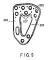
図9に示されるように、本発明の更に別の実施形態による骨プレート600は、骨プレート600の外形および窓608が異なる形状であることを除けば、骨プレート500とほぼ同様である。具体的には、骨プレート600の外形は、骨プレート100の外形とほぼ同様でありうる一方で、窓608は、第1壁602内へと延在する2つの陥凹607を有する長円形状に形成される。陥凹607は、第1壁602に隣接した骨ねじ(図示せず)の挿入を可能とするし、あるいは、そこを通した骨折部位の可視性を増大させるのに貢献する。 As shown in FIG. 9, a
図10に示されるように、本発明の別の実施形態による骨プレート700は、第2壁704および第3壁706の第2端部705から延在し骨幹に沿って延在するように構成された長手方向延長部740を有する、先の実施形態において示されたプレートに類似のほぼ三角形の端部を含む。加えて、骨プレート700の第1壁は、複数の可変角度のねじ穴、すなわち、使用者が(角度形成の許容された範囲内で)ねじ穴の軸に対する任意の所望の角度で、そこを通してねじを挿入することを可能とするねじ穴を備える。具体的には、第1壁は、互いに長手方向にオフセットされた4つのねじ穴710を含む可変角度のねじ穴の第1の列と、右側壁および左側壁に隣接する2つの可変角度のねじ穴710を有する第2の列と、を含む。しかしながら、ねじ穴710の数および配置は、本発明の趣旨および範囲からの逸脱なく変えられうること、および、固定角度の穴と可変角度の穴の任意の組み合わせが、所望に応じて含まれうることに留意されたい。当業者であれば理解するように、可変角度の穴710の各々は、そこに挿入される可変角度ねじの頭部に係合するようにその直径が選択される中心開口部712と共に、プレートを通って、中心開口部712の円周の周囲で互いに間隔を空けられた複数の周辺孔714(この例では4つの周辺孔714)を含む。周辺孔714の各々は、中心開口部712の壁がその円周の周囲で不連続となるように、中心開口部712へと通じている。当業者であれば理解するように、中心開口部712の中心軸に対する所望の角度で、各々のねじを対応するねじ穴710の一つに係止するために、中心開口部の壁は、そこを通して挿入されるねじの頭部の対応する特徴部に係合するように設計された、ねじ切りまたは一連の突起部を含む。中心開口部712は、中心軸に沿った、ほぼ砂時計型の外形を有する。すなわち、中心開口部712は、骨の外側を向く近位表面から骨に面する表面まで、プレート内へと延在し、その直径は、最大である近位表面から、最小であるねじの頭部に係合するように構成された中心部まで、中心軸にそって先細であり、そこから、中心部の直径よりも大きな直径を有する、骨に面する表面の開口部まで、外側に向かって広がっている。中心部における中心開口部712の壁、およびそこに設けられたねじ切りは、周辺孔714が中心開口部内へと通じている各々の場所において、間隙を含む。当業者であれば理解するように、中心開口部の、骨に面する広がった開口部、および周辺孔714は、その中に挿入される骨幹ねじに、例えば最大20度といった許容される範囲内で、中心軸に対して角度をつけることを可能とする。 As shown in FIG. 10, a
複数のK−ワイヤー穴716が、骨プレート700を骨上に一時的に位置づけるのに役立つように設けられる。骨プレート700を通って延在する窓は、ほぼ涙滴型をしており、第2端部705に向かって幅が減少する。長手方向延長部740は、互いに長手方向で整列する、第1結合穴726と、第2結合穴728と、を備える。当業者であれば理解するように、この実施形態における第1結合穴726は結合穴126とほぼ同様に形成される一方、第2結合穴は、互いに開口する2つのほぼ円形の部分を有する。可変角度の係止圧縮骨プレート700の外形は、長骨、または複数の骨折部位のある骨の固定に特に有用である。 A plurality of K-
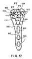
図11に示されるように、骨プレート800は、第1壁802において7つの可変角度のねじ穴810を含むが、その他の点では、上述のプレート700と同様に構成される。図12に示されるように、本発明の更に別の実施形態による骨プレート900は、その第1壁902が、プレート700のものと同様の可変角度の穴910に加えて、互いに隣接し、互いに開口している2つの可変角度の穴を含む可変角度の結合穴912を含むことを除けば、図10の骨プレート700とほぼ同様である。可変角度の結合穴912は、2つの中心開口部914であって、開口部914の近位端部が互いに交差するように、骨プレート900の近位表面(すなわち、骨の外側を向く面)における開口部914の直径よりも小さな距離で互いに隔てられた、それぞれの中心軸が隣り合う2つの中心開口部914を含む。加えて、中心開口部914の各々は、同じだけ離れた第4の周辺孔が2つの中心開口部914から互いに開口する間隙918の位置に置かれることによって定まる位置にある、3つの周辺孔916によって取り囲まれている。好適には、間隙918は、周辺孔916の各々によって形成される中心開口部914の壁における開口部よりも狭い。それ故、間隙918は、その中に挿入される骨ねじの頭部に係合するために利用可能な中心開口部914のねじ切り壁の範囲を減少させない。更に、骨プレート900の長手方向延長部940は、楕円形の結合穴926に加えて、2つのほぼ円形の結合穴928も備えている。骨プレート900は、その長手方向の中心線LCに沿ってほぼ対称となるように構成される。また、骨プレート900は、第1壁902上に設けられるほぼ円形の追加開口部909以外の点では図1の窓108とほぼ同様に形成される窓908も備え、開口部909は、窓908に隣接するように位置づけられ、窓908へと開口している。また、開口部909は、骨プレート900を通って、骨の外側を向く第1表面から骨に面する表面まで延在する。 As shown in FIG. 11, the
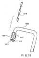
図13〜図16は、本発明の別の例示的実施形態による照準デバイス1000を示す。照準デバイス1000は、以下に強調される詳細を除けば、図4〜図5の照準デバイス200とほぼ同様である。照準デバイス1000は、ほぼ円筒形のかぎ状アーム1002と、長手部分1004と、尖端208とほぼ同様に形成される、カニューレを挿入された照準尖端1008を受け取るように構成されたかぎ状部分1006と、を備える。具体的には、カニューレを挿入された照準尖端1008は、医師または他の使用者による把持および操作に役立つように構成された、複数の長手方向の溝1010を有するほぼ円筒形の要素として形成される。照準尖端1008は、そこを通って延在する、照準アーム100のかぎ状部分1006を通って延在する孔1014と整列するように構成された、長手方向孔1012を備える。カニューレを挿入された照準尖端1008は、様々な直径のねじをそこに取り付けることを可能とするために、かぎ状アーム1006から取り外し可能に構成される。具体的には、カニューレを挿入された照準尖端1008は、選択的に取り外され、骨固定デバイス1032よりも大きなまたは小さな直径を有する骨固定デバイスへの取り付けを可能とするように構成された、またはそこを通してドリルビット1018または他のデバイスを挿入することを可能とするように構成された、別の尖端(図示せず)と交換されうる。同様に、以下により詳細に検討するように、そこを通して必要とされるドリルビット1018を挿入することを可能とするために、孔1014を必要に応じて寸法決めすることができる。カニューレを挿入された照準尖端1008は、その遠位端部に、橈骨茎状突起のほぼ中点に保持力を印加するために構成および寸法決めされた、1つまたは複数の棘部1016を更に備える。先に詳細に説明したように、照準デバイス100のかかる配置が、腱の合併症を回避するために、骨プレート100を骨10の分水界線に近接して置くことを可能とする。本発明の例示的なカニューレを挿入された照準尖端1008は、医師または他の使用者が、照準デバイス1000を目標のアライメントで骨上に配置した後に、骨に孔を開けるために、かぎ状部分1006を通してドリルビット1018を挿入することを可能とする。 13-16 illustrate an aiming
デバイス200と同様に、照準デバイス1000も、そこを通してアーム1002の長手部分1004を受け取るように構成された第1貫通穴1022をその第1端部に有するハンドル1020を備え、長手部分1004の一部に、それに沿ったハンドルの摺動移動を可能とするための軌道1024を備えている。ハンドルのアーム1002に対する位置を係止するために、締め付け機構1026が、ハンドル1020の第1端部に設けられる。ハンドル1020の第2端部は、そこを通して第1骨固定デバイス1030を挿入することを可能とするように構成された、第2貫通穴1028を備える。好適には、第1骨固定デバイス1030は、以下により詳細に説明されるように、骨プレート100のねじ穴110を通した挿入のために構成および寸法決めされる。 Similar to
本発明による例示的方法に従えば、骨プレート100は、先の実施形態に関して詳細に説明されたように、照準デバイス2000を使用して、骨(図示せず)の目標部位上に位置づけられる。適切に位置づけられると、その位置を骨上で係止するために、照準デバイス1000の締め付け機構1026が締め付けられる。係止された位置において、骨ピン218が骨プレート100のねじ穴110を通して位置づけられうるように、尖端1016が、骨の茎状突起のほぼ中点上に置かれる。次いで、骨の目標部位上の骨プレート100の所望の位置を一時的に固定するのに役立つように、骨プレート100のK−ワイヤー穴116を通してK−ワイヤーが挿入されうる。次いで、骨ねじ16が、ピン218に係合しているねじ穴110以外のねじ穴110内にねじ止めされる。 In accordance with an exemplary method according to the present invention,
次いで、医師または他の使用者は、ピン218を収容する孔に交わる孔を開けるために、かぎ状部分1006の孔1014を通してドリルビット1018を挿入しうる。具体的には、図14に示されるように、骨ピン218は、そこを通して延在し、そこを通してドリルビット1018の挿入を可能とするように構成された、開口部218を備えうる。したがって、ドリルビット1018が骨内部へと進むにつれて、その遠位端部が、骨ピン218の開口部219内へと延在しうる。ドリルビット1018が目標深度まで前進し、全ての目標骨ねじが骨プレート100を通して挿入されると、骨ピン218およびドリルビット1018は骨から取り外される。次いで、骨からの照準デバイス1000の取り外しを可能とするため、締め付け機構1026が解放されうる。次いで、第1骨固定デバイス1030が、骨プレート100のねじ穴110を通して挿入されうる。次いで、図16に示されるように、第2骨固定デバイス1032が、その遠位端部が第1骨固定デバイス1030の内部ねじ切りカニューレ1034内にねじ止めによって受け取られるまで、ドリルビット1018によって開けられた孔を通して挿入される。当業者であれば理解するように、カニューレ1034は、第2骨固定デバイス1032がその頭部が骨の茎状突起の外部表面に係合するまでその中にねじ込まれうるように選択された深さまで、第1骨固定デバイス1030の遠位部内に延在する。本発明による例示的な一実施形態において、第2骨固定デバイス1032は、平坦な外壁1036と、カニューレ1034内に受け取られるように構成された、減少直径ねじ切り部1038と、を備える。この実施形態において、第2骨固定デバイス1032は、ねじ切り部1038とカニューレ1034の内部ねじ切りとの係合によって、骨に対して係止される。しかしながら、別の実施形態においては、その骨内部における保持力を増加させるために、第2骨固定デバイス1032の外壁の任意の部分が、ねじ切りされうる。同様に、第1骨固定デバイス1030は、その外壁上に別個のねじ切り部分1040を有して示される。更に、本発明の範囲から逸脱することなく、骨固定デバイス1030の任意の部分に外部ねじ切りが設けられうることに留意されたい。 The physician or other user may then insert the
本発明の骨プレートには、本発明の範囲からの逸脱なく、任意の複数の他の特徴が備えられうることが当業者に理解されるであろう。具体的には、骨プレートには、骨とのアライメントに役立つように、任意の数の陥凹、湾曲、または屈曲が設けられうる。更に、骨プレートおよび窓は三角形状に限定されるものではなく、代替的に任意の他の環状形状(例えば、正方形、長方形、楕円形など)で形成されうる。 It will be appreciated by those skilled in the art that the bone plate of the present invention may be provided with any of a number of other features without departing from the scope of the present invention. In particular, the bone plate can be provided with any number of depressions, curvatures or bends to aid in alignment with the bone. Further, the bone plate and window are not limited to a triangular shape, but may alternatively be formed in any other annular shape (eg, square, rectangular, elliptical, etc.).
本発明の趣旨または範囲からの逸脱なく、本発明の構造および方法論に対して様々な修正および変形を行うことが可能であることが当業者には明白であろう。したがって、本発明は、本発明に対する修正および変形を、それが添付の特許請求の範囲内のもの、およびその均等物である限り、包含することが意図されている。 It will be apparent to those skilled in the art that various modifications and variations can be made to the structure and methodology of the present invention without departing from the spirit or scope of the invention. Accordingly, the present invention is intended to embrace modifications and variations to this invention so long as it is within the scope of the appended claims and their equivalents.
Claims (30)
Translated fromJapanese前記プレートを通って、前記プレートが目標骨上に所望の配向で搭載される場合に前記骨の外側を向く第1表面から、前記所望の配向にある場合に前記骨に面する第2表面まで延在する開口部であって、前記開口部は、前記プレートが前記骨の目標部位上に搭載される場合に、前記骨プレートのアライメントに役立つように、前記開口部を通して前記骨の骨折部分が可視であるように位置づけられる、開口部と、
前記プレートを通って、前記第1表面から前記第2表面まで延在する第1の穴および第2の穴であって、前記第1の穴および第2の穴の各々は、その中に挿入される骨固定デバイスのねじ頭部に係止して係合するように構造化される、第1の穴および第2の穴と、
を備える、骨固定プレート。A plate body extending from a first end to a second end, wherein the first end is configured and dimensioned for placement on a bone shaft, and the second end is the bone end. A plate configured and dimensioned for placement on the bone tip, wherein the outer diameter of the plate body increases from the first end to the second end so as to substantially match the size of the bone. The body,
Through the plate, from a first surface facing the outside of the bone when the plate is mounted in a desired orientation on a target bone to a second surface facing the bone when in the desired orientation An opening that extends through the opening to assist in the alignment of the bone plate when the plate is mounted on the target site of the bone. An opening positioned to be visible;
A first hole and a second hole extending through the plate from the first surface to the second surface, each of the first hole and the second hole being inserted therein; A first hole and a second hole structured to lock and engage the screw head of the bone fixation device
A bone fixation plate comprising:
かぎ状アームとハンドルとを有する照準デバイスであって、前記かぎ状アームは、遠位端に尖端を有する細長要素として構成され、前記目標骨の外側部に接触するために構成および寸法決めされており、前記ハンドルは、前記細長部に沿って摺動可能に位置づけることが可能であり、前記ハンドルを通して挿入される骨固定デバイスが前記骨固定プレートの前記第1の穴および第2の穴のうちの一方と整列するように、前記骨固定プレートに隣接して位置付けられる、照準デバイスと、
を備える、骨固定システム。A bone fixation plate, wherein the second end is configured and dimensioned for placement on the bone epiphysis from a first end configured and dimensioned for placement on the bone shaft. A plate body extending to a portion, wherein an outer diameter of the plate body increases from the first end to the second end so as to substantially match the size of the bone; and Extending through the plate from a first surface facing outwardly of the bone when the plate is mounted on the target bone in a desired orientation to a second surface facing the bone when in the desired orientation. An opening that is visible through the opening to assist in alignment of the bone plate when the plate is mounted on the target site of the bone. Positioned to be an opening And a first hole and a second hole extending through the plate from the first surface to the second surface, each of the first hole and the second hole being therein A bone fixation plate having a first hole and a second hole structured to lock the screw head of the bone fixation device inserted into the
A sighting device having a hooked arm and a handle, wherein the hooked arm is configured as an elongated element having a pointed tip at a distal end and configured and dimensioned to contact the outer portion of the target bone The handle can be slidably positioned along the elongated portion, and a bone fixation device inserted through the handle is included in the first hole and the second hole of the bone fixation plate. An aiming device positioned adjacent to the bone fixation plate to align with one of the
A bone fixation system comprising:
照準アームを、かぎ状アームの尖端が前記骨の目標外部表面上に位置づけられ、前記照準アームのハンドルを通して挿入される骨固定ピンが、前記骨固定プレートを通って延在する第1開口部および第2開口部のうちの目標となる一つの内部に位置づけられるように、前記骨固定プレート上に整列させることと、
前記ハンドルおよび骨固定ピンの位置を前記骨および骨固定プレートに対して固定するために、締め付け機構を締め付けることと、
骨固定デバイスを、前記第1の穴および第2の穴の他方を通して前記骨内部に挿入することと、
を含む、損傷した骨を固定するための方法。A bone fixation plate is placed over the bone, under visual guidance, through an opening extending through the plate so that the fractured target site of the bone is visible through the bone plate to help align the bone plate. The opening extends from a first surface facing the outside of the bone to a second surface facing the bone, and the bone fixation plate is configured for placement on the diaphysis And a plate body extending from a first dimensioned end to a second end configured and dimensioned for placement on the epiphysis of the bone, the outer diameter of the plate body being Locating, increasing from the first end to the second end so as to substantially match the size of the bone;
A first opening in which the aiming arm is positioned with the tip of the hooked arm positioned on the target external surface of the bone, and a bone fixation pin inserted through the handle of the aiming arm extends through the bone fixation plate; Aligning on the bone fixation plate so as to be positioned within a target one of the second openings;
Tightening a clamping mechanism to fix the position of the handle and bone fixation pin relative to the bone and bone fixation plate;
Inserting a bone fixation device into the bone through the other of the first hole and the second hole;
A method for fixing damaged bone, including:
Applications Claiming Priority (3)
| Application Number | Priority Date | Filing Date | Title |
|---|---|---|---|
| US26474509P | 2009-11-27 | 2009-11-27 | |
| US61/264,745 | 2009-11-27 | ||
| PCT/US2010/057802WO2011066280A1 (en) | 2009-11-27 | 2010-11-23 | Plating concept for distal radial fractures |
Publications (1)
| Publication Number | Publication Date |
|---|---|
| JP2013512042Atrue JP2013512042A (en) | 2013-04-11 |
Family
ID=43501609
Family Applications (1)
| Application Number | Title | Priority Date | Filing Date |
|---|---|---|---|
| JP2012541162APendingJP2013512042A (en) | 2009-11-27 | 2010-11-23 | Planar fixation concept for distal radius fractures |
Country Status (8)
| Country | Link |
|---|---|
| US (1) | US9370386B2 (en) |
| EP (1) | EP2503949A1 (en) |
| JP (1) | JP2013512042A (en) |
| KR (1) | KR101711003B1 (en) |
| CN (1) | CN102647953A (en) |
| BR (1) | BR112012007813A2 (en) |
| CA (1) | CA2775735C (en) |
| WO (1) | WO2011066280A1 (en) |
Families Citing this family (32)
| Publication number | Priority date | Publication date | Assignee | Title |
|---|---|---|---|---|
| EP4252686A3 (en) | 2012-12-28 | 2023-12-27 | Paragon 28, Inc. | Alignment guide apparatus |
| EP3052036B1 (en)* | 2013-10-01 | 2020-01-01 | DeGen Medical, Inc. | Osteosynthesis system, assemblies and components |
| US10231766B2 (en)* | 2013-12-23 | 2019-03-19 | Smith & Nephew, Inc. | Distal radius plate |
| US9839436B2 (en)* | 2014-06-03 | 2017-12-12 | Biomet Manufacturing, Llc | Patient-specific glenoid depth control |
| US9743965B2 (en)* | 2014-06-20 | 2017-08-29 | DePuy Synthes Products, Inc. | Medial column fusion plates |
| FR3023469B1 (en)* | 2014-07-10 | 2016-08-26 | In2Bones | IMPLANT AND SURGICAL KIT FOR MAINTAINING THE BONE BODIES OF A PATIENT IN RELATION TO OTHERS |
| US20160045238A1 (en) | 2014-08-13 | 2016-02-18 | Biomet C.V. | Calcaneal bone plate targeting guide |
| US9980760B2 (en) | 2014-11-19 | 2018-05-29 | Paragon 28, Inc. | Step off bone plates, systems, and methods of use |
| WO2017127295A1 (en)* | 2016-01-21 | 2017-07-27 | Biomet Manufacturing, Llc | Anatomic plates for medial proximal tibia |
| JP6936799B2 (en) | 2016-07-25 | 2021-09-22 | オリンパステルモバイオマテリアル株式会社 | Bone surgery compression device |
| EP3528716B1 (en) | 2016-10-24 | 2024-02-14 | Paragon 28, Inc. | Osteotomy systems |
| EP3585287B1 (en)* | 2017-02-27 | 2024-11-13 | Paragon 28, Inc. | Intramedullary nail fixation systems |
| ES2993743T3 (en) | 2017-02-27 | 2025-01-08 | Paragon 28 Inc | Targeting instruments and systems |
| US10918431B2 (en) | 2017-03-30 | 2021-02-16 | Paragon 28, Inc. | Bone fixation system, assembly, implants, devices, alignment guides, and methods of use |
| US11033333B2 (en) | 2017-04-06 | 2021-06-15 | Stryker European Holdings I, Llc | Plate selection user interface and design tool with database |
| KR101772535B1 (en) | 2017-05-23 | 2017-08-31 | 김윤기 | Assembly for adjustable bone plate having locking means and assembling method for same |
| EP3424452B1 (en) | 2017-06-16 | 2024-03-13 | Stryker European Operations Holdings LLC | Patient-specific bridging plates |
| EP3651699B1 (en) | 2017-07-11 | 2025-09-17 | Paragon 28, Inc. | Bone fixation system, assembly, implants, devices and insertion guides |
| US10639050B2 (en) | 2017-10-02 | 2020-05-05 | Robin Kamal | System and method for interosseous ligament reconstruction |
| RU2670086C1 (en)* | 2017-12-14 | 2018-10-18 | Государственное автономное учреждение здравоохранения "Республиканская клиническая больница Министерства здравоохранения Республики Татарстан" | Method for treatment of radial neck fractures in children |
| CN107951557A (en)* | 2018-01-03 | 2018-04-24 | 江苏荷普医疗科技股份有限公司 | Synthetism clamping device and synthetism locking system |
| US11026727B2 (en)* | 2018-03-20 | 2021-06-08 | DePuy Synthes Products, Inc. | Bone plate with form-fitting variable-angle locking hole |
| EP3820382B1 (en) | 2018-07-11 | 2025-09-10 | Paragon 28, Inc. | Systems comprising alignment guides and implants |
| US10849665B2 (en) | 2018-10-29 | 2020-12-01 | Stryker European Operations Holdings Llc | Snap-fit cutting guides and plating systems |
| CN109480990A (en)* | 2018-11-05 | 2019-03-19 | 大泗医疗生物科技有限公司 | Distal radius lockplate and distal radius locking structure |
| KR102018799B1 (en)* | 2018-12-12 | 2019-09-04 | 전남대학교산학협력단 | Fracture plate with bone graft injection means |
| EP3923842A4 (en) | 2019-02-13 | 2022-11-23 | Paragon 28, Inc. | IMPLANTS, ALIGNMENT GUIDES, SYSTEMS AND METHODS OF USE |
| JP7562547B2 (en) | 2019-02-14 | 2024-10-07 | パラゴン28・インコーポレイテッド | Threaded targeting instruments, systems, and methods of use |
| AU2020228309B2 (en) | 2019-02-28 | 2025-10-02 | Paragon 28, Inc. | Fusion systems, instruments, bone plates and methods of use |
| EP4248890B1 (en)* | 2022-03-23 | 2025-05-21 | Arthrex Inc | Veterinary distal humerus fracture plates |
| US20240050230A1 (en)* | 2022-08-12 | 2024-02-15 | Stryker European Operations Limited | Bone Plate With Tamp Window For Tibia Plateau Fracture |
| WO2025038956A1 (en)* | 2023-08-16 | 2025-02-20 | Ohio State Innovation Foundation | Methods for the design and manufacture of stiffness-matched implants for skeletal reconstructive surgery |
Citations (11)
| Publication number | Priority date | Publication date | Assignee | Title |
|---|---|---|---|---|
| JP2004223042A (en)* | 2003-01-24 | 2004-08-12 | Masayuki Kamano | Fracture reinforcement plate |
| US20050075641A1 (en)* | 2003-10-03 | 2005-04-07 | Linvatec Corporation | Osteotomy system |
| US20060173458A1 (en)* | 2004-10-07 | 2006-08-03 | Micah Forstein | Bone fracture fixation system |
| JP2006312062A (en)* | 2005-05-06 | 2006-11-16 | Inion Oy | Plate for fixing bone fragments to each other, its usage and mounting method |
| US20070123886A1 (en)* | 2003-11-05 | 2007-05-31 | Koenigsee Implantate U. Inst. Zur Osteosynth. Gmbh | Plate used to stabilise distal radius fractures |
| JP2007515990A (en)* | 2003-06-20 | 2007-06-21 | アキュームド・エルエルシー | Bone plate with openings that are threaded during surgery |
| US20070162018A1 (en)* | 2002-07-22 | 2007-07-12 | Jensen David G | Orthopedic systems |
| JP3141392U (en)* | 2008-02-21 | 2008-05-01 | 株式会社アラタ | Fracture site reinforcement plate |
| US20080140127A1 (en)* | 2006-12-06 | 2008-06-12 | Amei Technologies, Inc. | Volar plate fixation device |
| JP2008272485A (en)* | 2007-05-03 | 2008-11-13 | Medartis Ag | Fixing device, set screw, use of set screw, combination of fixing device and longitudinal element, configuration with combination and retaining structure, and osteosynthesis set |
| US20080300637A1 (en)* | 2005-07-25 | 2008-12-04 | Smith & Nephew, Inc. | Systems and methods for using polyaxial plates |
Family Cites Families (40)
| Publication number | Priority date | Publication date | Assignee | Title |
|---|---|---|---|---|
| JP3141392B2 (en) | 1990-10-31 | 2001-03-05 | 石川島播磨重工業株式会社 | Module frame for machine plant |
| US5197966A (en) | 1992-05-22 | 1993-03-30 | Sommerkamp T Greg | Radiodorsal buttress blade plate implant for repairing distal radius fractures |
| SE508120C2 (en) | 1995-01-27 | 1998-08-31 | Robert J Medoff | Implantable device comprising a pin plate and pins |
| SE505453C2 (en) | 1995-02-14 | 1997-09-01 | Robert J Medoff | Implantable support plate |
| DK1158915T3 (en)* | 1999-03-09 | 2004-11-08 | Synthes Ag | bone plate |
| CN2390564Y (en)* | 1999-03-28 | 2000-08-09 | 阎德强 | H shape arch bridge type bone fracture plate |
| CN2402279Y (en)* | 1999-07-23 | 2000-10-25 | 阎德强 | Rotating-preventing saddle condylar steel plate |
| US6767351B2 (en) | 2000-02-01 | 2004-07-27 | Hand Innovations, Inc. | Fixation system with multidirectional stabilization pegs |
| US6866665B2 (en) | 2003-03-27 | 2005-03-15 | Hand Innovations, Llc | Bone fracture fixation system with subchondral and articular surface support |
| US6440135B2 (en)* | 2000-02-01 | 2002-08-27 | Hand Innovations, Inc. | Volar fixation system with articulating stabilization pegs |
| US6358250B1 (en) | 2000-02-01 | 2002-03-19 | Hand Innovations, Inc. | Volar fixation system |
| US7282053B2 (en) | 2003-03-27 | 2007-10-16 | Depuy Products, Inc. | Method of using fracture fixation plate for performing osteotomy |
| US6283969B1 (en) | 2000-03-10 | 2001-09-04 | Wright Medical Technology, Inc. | Bone plating system |
| US7326212B2 (en) | 2002-11-19 | 2008-02-05 | Acumed Llc | Bone plates with reference marks |
| DE10125092A1 (en) | 2001-05-23 | 2001-12-06 | Miho Nicoloff | Osteosynthesis plate has two Y-shaped arms of different length/ |
| USD458374S1 (en) | 2001-11-13 | 2002-06-04 | Zimmer, Inc. | Orthopaedic bone plate |
| US7060330B2 (en) | 2002-05-08 | 2006-06-13 | Applied Materials, Inc. | Method for forming ultra low k films using electron beam |
| US20050171544A1 (en) | 2004-02-02 | 2005-08-04 | Acumed Llc | Bone plate with toothed aperture |
| AU2003294342A1 (en)* | 2002-11-19 | 2004-06-15 | Acumed Llc | Guide system for bone-repair devices |
| US7635381B2 (en) | 2003-03-27 | 2009-12-22 | Depuy Products, Inc. | Anatomical distal radius fracture fixation plate with fixed-angle K-wire holes defining a three-dimensional surface |
| DE502004010444D1 (en) | 2003-04-03 | 2010-01-14 | Medartis Ag | RECORDING FOR A BLOCKING ELEMENT AND BLOCKING ELEMENT |
| DE20309361U1 (en) | 2003-04-11 | 2003-09-18 | Königsee Implantate und Instrumente zur Ostheosynthese GmbH, 07426 Königsee | Osteosynthesis, especially an angle-stable radius plate, for the surgical treatment of bone fractures |
| JP4322039B2 (en) | 2003-04-17 | 2009-08-26 | 瑞穂医科工業株式会社 | Bone plate |
| DE10326643A1 (en)* | 2003-06-11 | 2004-12-30 | Mückter, Helmut, Dr. med. Dipl.-Ing. | Osteosynthesis plate or comparable implant with ball sleeve |
| AU2003291114A1 (en) | 2003-10-17 | 2004-06-06 | Acumed Llc | Bone plates with slots |
| US20050085818A1 (en) | 2003-10-17 | 2005-04-21 | Huebner Randall J. | Systems for distal radius fixation |
| DE502004010405D1 (en)* | 2004-02-20 | 2009-12-31 | Synthes Gmbh | TARGET DEVICE FOR INTRODUCING ANGLE STABILIZERS, LONG SCREWS IN THE ARTICULAR FIELD OF A BONE |
| US7137987B2 (en) | 2004-07-02 | 2006-11-21 | Wright Medical Technology, Inc. | Distal radius bone plating system with locking and non-locking screws |
| JP4367849B2 (en) | 2004-09-22 | 2009-11-18 | 孝昭 石井 | Method to promote fruit ripening |
| US8062296B2 (en) | 2005-03-17 | 2011-11-22 | Depuy Products, Inc. | Modular fracture fixation plate system with multiple metaphyseal and diaphyseal plates |
| US8172886B2 (en) | 2004-12-14 | 2012-05-08 | Depuy Products, Inc. | Bone plate with pre-assembled drill guide tips |
| DE102005004841B4 (en) | 2004-12-30 | 2009-10-29 | Königsee Implantate und Instrumente zur Osteosynthese GmbH | Osteosynthesis plate with a variety of holes for receiving bone screws |
| WO2006099766A1 (en) | 2005-03-24 | 2006-09-28 | Medartis Ag | Bone plate |
| US7993380B2 (en)* | 2005-03-31 | 2011-08-09 | Alphatel Spine, Inc. | Active compression orthopedic plate system and method for using the same |
| CN100349552C (en)* | 2005-10-19 | 2007-11-21 | 中国人民解放军第三军医大学第一附属医院 | Front self locking fixing pin plate for lumbar vertebra |
| US20070123881A1 (en)* | 2005-10-26 | 2007-05-31 | Ralph James D | Off-set bone plates |
| US8021402B2 (en)* | 2006-03-07 | 2011-09-20 | Orthohelix Surgical Designs, Inc. | Distal radius plate |
| AU2009215830B2 (en)* | 2008-02-19 | 2012-07-12 | Stryker Corporation | Orthopedic plates for use in the midfoot |
| CN201308534Y (en)* | 2008-12-04 | 2009-09-16 | 朱悦 | Anterior cervical steel plate |
| CN101536928A (en)* | 2009-04-13 | 2009-09-23 | 崔勇 | Distal tibial anterolateral anatomical bone plate |
- 2010
- 2010-11-23JPJP2012541162Apatent/JP2013512042A/enactivePending
- 2010-11-23EPEP10784413Apatent/EP2503949A1/ennot_activeWithdrawn
- 2010-11-23USUS12/952,756patent/US9370386B2/enactiveActive
- 2010-11-23CNCN2010800531547Apatent/CN102647953A/enactivePending
- 2010-11-23WOPCT/US2010/057802patent/WO2011066280A1/enactiveApplication Filing
- 2010-11-23CACA2775735Apatent/CA2775735C/enactiveActive
- 2010-11-23BRBR112012007813Apatent/BR112012007813A2/ennot_activeApplication Discontinuation
- 2010-11-23KRKR1020127008540Apatent/KR101711003B1/enactiveActive
Patent Citations (11)
| Publication number | Priority date | Publication date | Assignee | Title |
|---|---|---|---|---|
| US20070162018A1 (en)* | 2002-07-22 | 2007-07-12 | Jensen David G | Orthopedic systems |
| JP2004223042A (en)* | 2003-01-24 | 2004-08-12 | Masayuki Kamano | Fracture reinforcement plate |
| JP2007515990A (en)* | 2003-06-20 | 2007-06-21 | アキュームド・エルエルシー | Bone plate with openings that are threaded during surgery |
| US20050075641A1 (en)* | 2003-10-03 | 2005-04-07 | Linvatec Corporation | Osteotomy system |
| US20070123886A1 (en)* | 2003-11-05 | 2007-05-31 | Koenigsee Implantate U. Inst. Zur Osteosynth. Gmbh | Plate used to stabilise distal radius fractures |
| US20060173458A1 (en)* | 2004-10-07 | 2006-08-03 | Micah Forstein | Bone fracture fixation system |
| JP2006312062A (en)* | 2005-05-06 | 2006-11-16 | Inion Oy | Plate for fixing bone fragments to each other, its usage and mounting method |
| US20080300637A1 (en)* | 2005-07-25 | 2008-12-04 | Smith & Nephew, Inc. | Systems and methods for using polyaxial plates |
| US20080140127A1 (en)* | 2006-12-06 | 2008-06-12 | Amei Technologies, Inc. | Volar plate fixation device |
| JP2008272485A (en)* | 2007-05-03 | 2008-11-13 | Medartis Ag | Fixing device, set screw, use of set screw, combination of fixing device and longitudinal element, configuration with combination and retaining structure, and osteosynthesis set |
| JP3141392U (en)* | 2008-02-21 | 2008-05-01 | 株式会社アラタ | Fracture site reinforcement plate |
Also Published As
| Publication number | Publication date |
|---|---|
| BR112012007813A2 (en) | 2017-09-19 |
| US20110218576A1 (en) | 2011-09-08 |
| CA2775735C (en) | 2018-01-02 |
| CN102647953A (en) | 2012-08-22 |
| WO2011066280A1 (en) | 2011-06-03 |
| KR101711003B1 (en) | 2017-02-28 |
| EP2503949A1 (en) | 2012-10-03 |
| KR20120112377A (en) | 2012-10-11 |
| US9370386B2 (en) | 2016-06-21 |
| CA2775735A1 (en) | 2011-06-03 |
| WO2011066280A9 (en) | 2011-08-04 |
Similar Documents
| Publication | Publication Date | Title |
|---|---|---|
| JP2013512042A (en) | Planar fixation concept for distal radius fractures | |
| AU2004249313B2 (en) | Bone plates with intraoperatively tapped apertures | |
| US6364882B1 (en) | Volar fixation system | |
| US8764808B2 (en) | Bone fixation system | |
| EP2227160B1 (en) | Distal tibia plating system | |
| US9247946B2 (en) | Method of using a drill sleeve | |
| US9662153B2 (en) | Guide assembly for intramedullary fixation and method of using the same | |
| US9492213B2 (en) | Volar fixation system | |
| JP4811673B2 (en) | Intramedullary fixation assembly and its installation apparatus and method | |
| EP1847228A1 (en) | Fixation plate with multifunctional holes | |
| EP3801322B1 (en) | Systems for fusion of anatomical joints | |
| US8668693B2 (en) | Fixation device for proximal elbow fractures and method of using same | |
| CA2640225A1 (en) | A fracture fixation device and implantation jig therefor | |
| RU2762481C1 (en) | Palmar (volar) fixation device for osteosynthesis in the treatment of fractures of the distal radius | |
| GB2437441A (en) | A system for tapping apertures in a bone plate |
Legal Events
| Date | Code | Title | Description |
|---|---|---|---|
| A621 | Written request for application examination | Free format text:JAPANESE INTERMEDIATE CODE: A621 Effective date:20131107 | |
| A977 | Report on retrieval | Free format text:JAPANESE INTERMEDIATE CODE: A971007 Effective date:20140725 | |
| A131 | Notification of reasons for refusal | Free format text:JAPANESE INTERMEDIATE CODE: A131 Effective date:20140826 | |
| A521 | Request for written amendment filed | Free format text:JAPANESE INTERMEDIATE CODE: A523 Effective date:20141112 | |
| A02 | Decision of refusal | Free format text:JAPANESE INTERMEDIATE CODE: A02 Effective date:20150224 |