JP2013509751A - Wireless remote unit link self-adaptive method and apparatus - Google Patents
Wireless remote unit link self-adaptive method and apparatusDownload PDFInfo
- Publication number
- JP2013509751A JP2013509751AJP2012535596AJP2012535596AJP2013509751AJP 2013509751 AJP2013509751 AJP 2013509751AJP 2012535596 AJP2012535596 AJP 2012535596AJP 2012535596 AJP2012535596 AJP 2012535596AJP 2013509751 AJP2013509751 AJP 2013509751A
- Authority
- JP
- Japan
- Prior art keywords
- rru
- information
- identifier
- acquisition request
- request information
- Prior art date
- Legal status (The legal status is an assumption and is not a legal conclusion. Google has not performed a legal analysis and makes no representation as to the accuracy of the status listed.)
- Granted
Links
- 238000000034methodMethods0.000titleclaimsabstractdescription41
- 230000004044responseEffects0.000claimsabstractdescription91
- 238000012790confirmationMethods0.000claimsdescription23
- 230000005540biological transmissionEffects0.000claimsdescription16
- 238000012546transferMethods0.000claimsdescription12
- 230000006855networkingEffects0.000description13
- 238000012545processingMethods0.000description8
- 230000008569processEffects0.000description7
- 238000010586diagramMethods0.000description5
- 239000013307optical fiberSubstances0.000description4
- 238000005516engineering processMethods0.000description3
- 238000013507mappingMethods0.000description3
- 238000004891communicationMethods0.000description2
- 238000012423maintenanceMethods0.000description2
- 230000003068static effectEffects0.000description2
- 230000003044adaptive effectEffects0.000description1
- 238000012937correctionMethods0.000description1
- 238000012986modificationMethods0.000description1
- 230000004048modificationEffects0.000description1
- 230000003287optical effectEffects0.000description1
- 238000011084recoveryMethods0.000description1
- 238000006467substitution reactionMethods0.000description1
Images


Classifications
- H—ELECTRICITY
- H04—ELECTRIC COMMUNICATION TECHNIQUE
- H04W—WIRELESS COMMUNICATION NETWORKS
- H04W24/00—Supervisory, monitoring or testing arrangements
- H04W24/06—Testing, supervising or monitoring using simulated traffic
- H—ELECTRICITY
- H04—ELECTRIC COMMUNICATION TECHNIQUE
- H04W—WIRELESS COMMUNICATION NETWORKS
- H04W72/00—Local resource management
- H04W72/20—Control channels or signalling for resource management
- H—ELECTRICITY
- H04—ELECTRIC COMMUNICATION TECHNIQUE
- H04W—WIRELESS COMMUNICATION NETWORKS
- H04W88/00—Devices specially adapted for wireless communication networks, e.g. terminals, base stations or access point devices
- H04W88/08—Access point devices
- H—ELECTRICITY
- H04—ELECTRIC COMMUNICATION TECHNIQUE
- H04W—WIRELESS COMMUNICATION NETWORKS
- H04W92/00—Interfaces specially adapted for wireless communication networks
- H04W92/04—Interfaces between hierarchically different network devices
- H04W92/12—Interfaces between hierarchically different network devices between access points and access point controllers
Landscapes
- Engineering & Computer Science (AREA)
- Computer Networks & Wireless Communication (AREA)
- Signal Processing (AREA)
- Mobile Radio Communication Systems (AREA)
- Small-Scale Networks (AREA)
- Communication Control (AREA)
Abstract
Translated fromJapaneseDescription
Translated fromJapanese本発明は通信分野に関し、特に、無線リモートユニットのリンク自己適応方法及び装置に関する。 The present invention relates to the field of communications, and more particularly, to a link self-adaptive method and apparatus for a wireless remote unit.
共通公衆無線インターフェイス(Common Public Radio Interface: CPRI)は、基地局において、ベースバンドユニット(Base Band Unit: BBU)と無線リモートユニット(Radio Remote Unit:RRU)との間のインターフェイスを実現する規格である。このインターフェイスは、基地局における分散型の機器構成の実現をサポートしている。従来の基地局における無線制御部(Radio Equipment Control: REC)及び無線部(Radio Equipment: RE)は、一体的に構成されているので、多くの欠点を有していた。一方で、分散型基地局では、REとRECとが分離されて構成されており、中心となる1つのRECが複数のREを管理及び設定することができる。これにより、基地局において、高速かつ柔軟な機器構成及びネットワーキングが実現され、オペレーターの資本支出及び運営支出が低減され、また、サービスの拡大を実現することが可能となった。CPRIプロトコルがサポートするネットワーキング方式は、チェーン型のネットワーキング、リング型のネットワーキング、ツリー型のネットワーキングを含む。 Common Public Radio Interface (CPRI) is a standard that realizes an interface between a baseband unit (BBU) and a radio remote unit (RRU) in a base station. . This interface supports the realization of a distributed device configuration in the base station. Since the radio control unit (Radio Equipment Control: REC) and the radio unit (Radio Equipment: RE) in the conventional base station are integrally configured, they have many drawbacks. On the other hand, in the distributed base station, the RE and the REC are separated from each other, and one central REC can manage and set a plurality of REs. As a result, high-speed and flexible equipment configuration and networking are realized in the base station, and the capital expenditure and operational expenditure of the operator are reduced, and the service can be expanded. Networking methods supported by the CPRI protocol include chain type networking, ring type networking, and tree type networking.
REの分散型構成を実現するために、REとRECの間には、制御情報及び同期情報を伝送する必要があり、また、REとRECの間には、デジタルベースバンドに対応するデジタルインターフェイスを用いる必要がある。CPRIは、このインターフェイスの物理層及びデータリンク層を定義している。物理層については、接続媒介(光ファイバーによるインターフェイス)と、アダプティブ速度(3タイプのREに対応する、641.4Mbps、1228.8Mbps、2457.6Mbpsの3種類の速度をサポート)と、クロック回復と、データ符号化のフォーマットとを規定している。データリンク層については、遅延修正方式と時分割多重化方式(フレームフォーマット)を規定している。ネットワーキングを実現するために、データのホームREが構成され、また、交換層が定義される。これにより、異なるRE間のデータ交換、並びにRE及びREC間のデータ交換が実現される。マッピング層では、異なるユーザデータプレーンへのフレームマッピングが実現され、フレームマッピング方法は、ユーザにより柔軟に設定することができる。 In order to realize a distributed configuration of RE, it is necessary to transmit control information and synchronization information between RE and REC, and between RE and REC, a digital interface corresponding to digital baseband is required. It is necessary to use it. CPRI defines the physical layer and data link layer of this interface. For the physical layer, connection mediation (optical fiber interface), adaptive speed (supports three types of 641.4Mbps, 1228.8Mbps, and 2457.6Mbps corresponding to three types of RE), clock recovery, and data encoding Format. For the data link layer, a delay correction method and a time division multiplexing method (frame format) are defined. In order to realize networking, a data home RE is configured and an exchange layer is defined. Thereby, data exchange between different REs and data exchange between REs and RECs are realized. In the mapping layer, frame mapping to different user data planes is realized, and the frame mapping method can be set flexibly by the user.
現在のRRUのカスケードには、静的なトポロジー構造が採用されおり、このトポロジー構造は、BBUにより静的に構成され、動的に変化させることができない。従って、トポロジー構造の柔軟性が制限され、RRUに動的かつランダムにアクセスすることができない。従って、RRUとBBUの間のリンクが一度切れてしまったり、或る特定のRRUが損傷してしまったりすると、下位の各RRUが通常どおり動作することができなくなってしまい、ネットワーク全体の信頼性に影響を及ぼしてしまう。 The current RRU cascade employs a static topology structure, which is statically configured by the BBU and cannot be changed dynamically. Therefore, the flexibility of the topology structure is limited and the RRU cannot be accessed dynamically and randomly. Therefore, if the link between the RRU and the BBU is broken once or a specific RRU is damaged, each lower RRU cannot operate normally, and the reliability of the entire network Will be affected.
上記のRRUトポロジー構造に静的な構成が採用されているために、ネットワークの信頼性が下がってしまうという課題について、関連技術において効果的な解決方案は、未だ提案されていない。 Since the static configuration is adopted for the above RRU topology structure, an effective solution for the problem that the reliability of the network is lowered has not yet been proposed in related technologies.
本発明の主な目的は、従来技術においてRRUトポロジー構造の信頼性が低いといった問題を解決することができる無線リモートユニットリンク自己適応方法及び装置を提供することにある。 A main object of the present invention is to provide a wireless remote unit link self-adaptive method and apparatus capable of solving the problem that the reliability of the RRU topology structure is low in the prior art.
上記目的を達成するために、本発明の技術的解決法は以下のように実現される。 In order to achieve the above object, the technical solution of the present invention is realized as follows.
本技術に係る無線リモートユニットのリンク自己適応方法は、
無線リモートユニット(Radio Remote Unit :RRU)が、自身のポートを介して識別子取得要求情報を定期的に放送することと、
前記RRUが、前記識別子取得要求情報の応答情報を受信することと、
前記応答情報が、ベースバンドユニット(Base Band Unit :BBU)からの識別子割り当て応答情報である場合、前記RRUが、当該応答情報に含まれる割り当て識別子に応じて、上位層リンクを確立することとを含む。The link self-adaptation method of the wireless remote unit according to the present technology is as follows:
The radio remote unit (Radio Remote Unit: RRU) periodically broadcasts identifier acquisition request information via its own port,
The RRU receives response information of the identifier acquisition request information;
When the response information is identifier assignment response information from a base band unit (BBU), the RRU establishes an upper layer link according to the assignment identifier included in the response information. Including.
前記RRUによって受信された応答情報が、前記RRUの上位RRUからの確認情報である場合、当該方法は、
前記RRUが、複数の前記上位RRUからの確認情報を受信した場合、前記複数の上位RRUのうち、識別子情報が最小であるRRUに二次ハンドシェーク識別子取得要求情報を送信し、または、前記RRUが、1つの前記上位RRUからの確認情報を受信した場合、二次ハンドシェーク識別子取得要求情報を前記上位RRUに送信することと、
前記RRUが、前記上位RRUを介して前記BBUからの識別子割り当て応答情報を受信し、且つ前記応答情報に含まれる割り当て識別子に応じて、上位層リンクを確立することとを更に含んでいてもよい。When the response information received by the RRU is confirmation information from the upper RRU of the RRU, the method includes:
When the RRU receives confirmation information from a plurality of the upper RRUs, it transmits secondary handshake identifier acquisition request information to the RRU having the smallest identifier information among the plurality of upper RRUs, or the RRU When receiving confirmation information from one upper RRU, sending secondary handshake identifier acquisition request information to the upper RRU;
The RRU may further include receiving identifier assignment response information from the BBU via the upper RRU and establishing an upper layer link according to the assignment identifier included in the response information. .
前記RRUが、自身のポートを介して識別子取得要求情報を送信する前に、当該方法は、
前記RRUが、自身の物理ポート情報を取得することを更に含んでいてもよい。Before the RRU sends the identifier acquisition request information through its own port, the method
The RRU may further include acquiring its own physical port information.
当該方法は、
前記RRUが、前記RRUの下位RRUからの識別子取得要求情報を受信することと、
前記RRUが、当該識別子取得要求情報の確認情報を前記RRUの下位RRUに送信することとを更に含んでいてもよい。The method is
The RRU receives identifier acquisition request information from a subordinate RRU of the RRU;
The RRU may further include transmitting confirmation information of the identifier acquisition request information to a lower RRU of the RRU.
当該方法は、
前記RRUが、前記RRUの下位RRUからの二次ハンドシェーク識別子取得要求情報を受信することと、
前記RRUが、前記二次ハンドシェーク識別子取得要求情報を前記BBUに転送することと、
前記RRUが、前記BBUからの識別子割り当て応答情報を受信した後に、前記識別子割り当て応答情報を前記RRUの下位RRUに転送することとを更に含んでいてもよい。The method is
The RRU receives secondary handshake identifier acquisition request information from a lower RRU of the RRU; and
The RRU forwards the secondary handshake identifier acquisition request information to the BBU;
The RRU may further include transferring the identifier assignment response information to a lower RRU of the RRU after receiving the identifier assignment response information from the BBU.
当該方法は、
前記BBUが、前記RRUからの識別子取得要求情報を受信し、識別子を前記RRUに割り当て、前記識別子を前記RRUに送信することと、
前記BBUが、ネットワークトポロジー構造を更新することとを更に含んでいてもよい。The method is
The BBU receives identifier acquisition request information from the RRU, assigns an identifier to the RRU, and transmits the identifier to the RRU;
The BBU may further include updating the network topology structure.
本技術に係る無線リモートユニット(Radio Remote Unit :RRU)のリンク自己適応実行装置は、
ポートを介して識別子取得要求情報を定期的に放送する第1の送信モジュールと、
前記識別子取得要求情報の応答情報を受信する第1の受信モジュールと、
前記第1の受信モジュールによって受信された応答情報が、ベースバンドユニット(Base Band Unit :BBU)からの識別子割り当て応答情報である場合に、前記応答情報に含まれる割り当て識別子に応じて、上位層リンクを確立する確立モジュールとを含む。Radio remote unit (RRU) link self-adaptive execution device according to this technology
A first transmission module for periodically broadcasting identifier acquisition request information via a port;
A first receiving module for receiving response information of the identifier acquisition request information;
If the response information received by the first receiving module is identifier assignment response information from a base band unit (BBU), an upper layer link is determined according to the assignment identifier included in the response information. And an establishment module for establishing.
当該装置は、
前記第1の受信モジュールによって受信された応答情報が、複数の上位RRUからの確認情報である場合に、前記複数の上位RRUのうち、識別子情報が最小であるRRUに二次ハンドシェーク識別子取得要求情報を送信し、前記第1の受信モジュールによって受信された応答情報が、1つの上位RRUからの確認情報である場合に、二次ハンドシェーク識別子取得要求情報を前記上位RRUに送信する第2の送信モジュールと、
前記上位RRUを介して前記BBUからの識別子割り当て応答情報を受信する第2の受信モジュールとを更に含んでいてもよい。The device is
When the response information received by the first receiving module is confirmation information from a plurality of upper RRUs, secondary handshake identifier acquisition request information is sent to the RRU having the smallest identifier information among the plurality of upper RRUs. The second transmission module that transmits secondary handshake identifier acquisition request information to the upper RRU when the response information received by the first reception module is confirmation information from one upper RRU. When,
And a second receiving module that receives the identifier assignment response information from the BBU via the upper RRU.
当該装置は、
物理ポート情報を取得する取得モジュールを更に含んでいてもよい。The device is
An acquisition module that acquires physical port information may be further included.
当該装置は、
前記識別子取得要求情報を受信する第3の受信モジュールと、
前記第3の受信モジュールが、下位RRUからの識別子取得要求情報を受信した場合に、前記識別子取得要求情報の確認情報を前記下位RRUに送信し、前記第3の受信モジュールが下位RRUからの二次ハンドシェーク識別子取得要求情報を受信した場合に、前記二次ハンドシェーク識別子取得要求情報を前記BBUに転送する第3の送信モジュールとを更に含んでいてもよい。The device is
A third receiving module for receiving the identifier acquisition request information;
When the third receiving module receives the identifier acquisition request information from the lower RRU, the third receiving module transmits confirmation information of the identifier acquisition request information to the lower RRU, and the third receiving module receives the second information from the lower RRU. A third transmission module that transfers the secondary handshake identifier acquisition request information to the BBU when the next handshake identifier acquisition request information is received may be further included.
本発明の上記の技術的解決法によれば、RRUによりIDの要求が主体的に開始され、BBUによりトポロジー構造が動的に更新され、トポロジー構造が動的に確立される。これにより、ネットワーキングが更に柔軟になり、REC及びREのネットワーキングの柔軟性を十分に発揮させることができる。また、下位RRUと、上位RRUとの間で複数の物理パスが確立されるので、或る特定のRRUが損傷してしまったり、或る特定の位置で光ファイバーが切れてしまったりしても、下位RRUが影響を受けない。これにより、ネットワーキングの信頼性が向上し、運営・メンテナンスのコストを節約することができる。 According to the above technical solution of the present invention, an ID request is initiated mainly by the RRU, the topology structure is dynamically updated by the BBU, and the topology structure is dynamically established. As a result, networking becomes more flexible, and the networking flexibility of REC and RE can be fully exhibited. Also, since multiple physical paths are established between the lower RRU and the upper RRU, even if a specific RRU is damaged or an optical fiber is cut at a specific position, Inferior RRU is not affected. Thereby, the reliability of networking can be improved, and the cost of operation and maintenance can be saved.
以下、本発明の目的、技術解決法及び利点を更に明らかにするために、図面及び具体的な実施形態を参照して本発明を更に詳しく説明する。 Hereinafter, the present invention will be described in more detail with reference to the drawings and specific embodiments in order to further clarify the objects, technical solutions, and advantages of the present invention.
本発明の実施形態によれば、無線リモートユニットのリンク自己適応方法が提供される。 According to an embodiment of the present invention, a link self-adaptation method for a wireless remote unit is provided.
図1は、本発明の実施形態に係る無線リモートユニットのリンク自己適応方法のフローチャートである。図1に示すように、当該方法は、以下のステップを含む。 FIG. 1 is a flowchart of a link self-adaptation method for a wireless remote unit according to an embodiment of the present invention. As shown in FIG. 1, the method includes the following steps.
ステップ102:RRUは、自身のポートを介して識別子(ID)取得要求情報を定期的に放送する。 Step 102: The RRU periodically broadcasts identifier (ID) acquisition request information via its own port.
ステップ104:RRUは、識別子(ID)取得要求情報の応答情報を受信する。 Step 104: The RRU receives the response information of the identifier (ID) acquisition request information.
ステップ106:RRUによって受信された応答情報が、BBUからの識別子割り当て応答情報である場合、RRUは、当該応答情報に含まれる割り当て識別子に応じて、上位層リンクを確立する。 Step 106: If the response information received by the RRU is the identifier assignment response information from the BBU, the RRU establishes an upper layer link according to the assignment identifier included in the response information.
さらに、CPRIプロトコルを用いて、無線通信基地局におけるBBUとRRUの接続が確立される。具体的に、上記の各処理は、以下のステップを更に含んでいてもよい。 Furthermore, the connection between the BBU and RRU in the radio communication base station is established using the CPRI protocol. Specifically, each of the above processes may further include the following steps.
ステップ1:光ファイバがRRUに接続され、電源がオンとなった後に、物理層(CPRI)が自動的に接続される。 Step 1: After the optical fiber is connected to the RRU and the power is turned on, the physical layer (CPRI) is automatically connected.
ステップ2:物理層が接続された後に、RRUが自身の物理ポート番号を取得する。 Step 2: After the physical layer is connected, the RRU acquires its physical port number.
ステップ3: RRUは、ポート番号(NextP)を結合し、ID取得要求情報の送信を主体的に開始する。 Step 3: The RRU binds the port number (NextP) and initiates transmission of ID acquisition request information.
ステップ4:上位RRUは、下位RRUのID取得要求情報を受信した後に、ポート番号を確認し、下位RRUにポート番号確認情報を返信する。 Step 4: After receiving the ID acquisition request information of the lower RRU, the upper RRU confirms the port number and returns the port number confirmation information to the lower RRU.
ステップ5:IDを要求したRRUは、上位RRUからのポート番号確認情報に応答し、上位RRUは、この応答を受信した後に、さらに上位RRUにID取得要求情報を転送する。同じレベルのRRUによってID取得要求転送情報が受信された場合、この転送情報は、上位のRRUに直接的に転送される。 Step 5: The RRU that requested the ID responds to the port number confirmation information from the upper RRU. After receiving the response, the upper RRU further transfers the ID acquisition request information to the upper RRU. When the ID acquisition request transfer information is received by the RRU of the same level, this transfer information is directly transferred to the upper RRU.
ステップ6:BBUは、RRUのID取得要求情報を受信し、RRUにIDを割り当て、トポロジー構造を動的に更新する。 Step 6: The BBU receives the RRU ID acquisition request information, assigns an ID to the RRU, and dynamically updates the topology structure.
ステップ7:RRUは、IDを取得した後に、上位層リンクを確立し、コンフィギュレーションを取得する。 Step 7: After obtaining the ID, the RRU establishes the upper layer link and obtains the configuration.
CPRIプロトコルでは、256個のBFが、マルチフレームとよばれる基本シグナルユニットとされており、このマルチフレームは、カスタムフィールド(vendor specific)を含む。制御フィールド内の各データブロックの定義が表1に示されている。 In the CPRI protocol, 256 BFs are basic signal units called multiframes, and the multiframes include a custom field (vendor specific). The definition of each data block in the control field is shown in Table 1.

本発明の実施形態では、表1のようなVendor specific空間に共通制御チャネルのパケットのフォーマットが定義される。図2を参照して、CC_WORD(Common Control Word)は、チャネルポインタであり、このチャネルポインタは、制御フィールドタイプを識別し、また、2バイト (Byte) の情報を含む。2バイトの情報のうち、第1のバイト(Local_ID)は、ローカルのRRU_IDを識別し、第2のバイト(ID_RQ)は、下位要求識別子を識別し、0xFFは、ID取得要求識別子を示す。ID_Indexは、IDのレベル関係を示し、後続のIDフィールド位置を示し、2バイトの情報を含む。2バイトの情報のうち、第1のバイト(Local_Index) は、ローカルのID_Indexを識別し、第2のバイト(Next_Index)は、下位ID_Indexを識別する。ID_WORDは、RRU_ID、LocalP及びNextPを含む。ID_WORDにおいて、ID番号は1つのバイトを占有し、LocalP及びNextPは、それぞれ上位ポート番号及び下位ポート番号を示し、それぞれ4ビットを占有する。0xFは、無効であることを示す。表1に示す3つのカスタムフィールドの位置は、ただの例示であり、具体的な状況に応じて選択可能である。ここで、一例として線速度が1228.8Mであり、線速度が高いような場合、バイトの大きさはそれに応じて、調節することができる。 In the embodiment of the present invention, the packet format of the common control channel is defined in the Vendor specific space as shown in Table 1. Referring to FIG. 2, CC_WORD (Common Control Word) is a channel pointer, and this channel pointer identifies a control field type and includes 2 bytes of information. Of the 2-byte information, the first byte (Local_ID) identifies the local RRU_ID, the second byte (ID_RQ) identifies the lower request identifier, and 0xFF indicates the ID acquisition request identifier. ID_Index indicates the ID level relationship, indicates the subsequent ID field position, and includes 2-byte information. Of the 2-byte information, the first byte (Local_Index) identifies the local ID_Index, and the second byte (Next_Index) identifies the lower ID_Index. ID_WORD includes RRU_ID, LocalP, and NextP. In ID_WORD, the ID number occupies one byte, and LocalP and NextP indicate an upper port number and a lower port number, respectively, and occupy 4 bits each. 0xF indicates invalidity. The positions of the three custom fields shown in Table 1 are merely examples, and can be selected according to a specific situation. Here, as an example, when the linear velocity is 1228.8M and the linear velocity is high, the size of the bite can be adjusted accordingly.
RRUは、マルチフレーム全体の受信が完了した後、CC_WORDの値に応じて、どのように処理を行うかを判断する。複数のポートから有効なマルチフレームが同時に受信された場合、RRUは、マルチフレームを記憶(キューイング)し、記憶されたマルチフレームをアイドル時に処理する必要がある。 The RRU determines how to perform processing according to the value of CC_WORD after the reception of the entire multiframe is completed. If valid multiframes are received simultaneously from multiple ports, the RRU must store (queue) the multiframes and process the stored multiframes when idle.
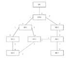
以下、図3と図4を参照して本発明の実施形形態を詳しく説明する。図4では、実線は、物理的に接続され、かつ、物理的に構成されたリンクを示しており、破線は、単に物理的に接続されただけのリンクを示している。また、RRUにおける4方向の光ポ?ト番号は、それぞれ0、1、2、3と定義される。図4におけるRRU番号は、RRU_IDと設定されている。 Hereinafter, embodiments of the present invention will be described in detail with reference to FIGS. 3 and 4. In FIG. 4, a solid line indicates a physically connected and physically configured link, and a broken line indicates a link that is merely physically connected. The optical port numbers in the four directions in the RRU are defined as 0, 1, 2, and 3, respectively. The RRU number in FIG. 4 is set as RRU_ID.
実施形態1
ステップ1:RRUは、起動後の初期状態であるか、あるいはIDが割り当てられていない状態にある。あるいは、RRUは、IDを再び割り当てる必要がある状態にある。このときRRU_IDは0xFFであり、RRUは、いかなるポート情報も転送しない。
Step 1: The RRU is in the initial state after startup, or is not assigned an ID. Alternatively, the RRU is in a state that needs to be reassigned an ID. At this time, RRU_ID is 0xFF, and RRU does not transfer any port information.
ステップ2:当該RRUは、すべての既知のポートにID取得要求パケットを定期的に放送する。対応するパケットにおけるフィールドの内容は、CC_WORD=0xFF、ID_Index=0xFFである。ID_WORDの内容は、RRU_ID=0xFF、LocalP=port number L=0xFであり、これは、最初の開始要求を示しており、また、NextP=port number N=0、1、2、3であり、これは、要求側のポート番号を示す。 Step 2: The RRU periodically broadcasts an ID acquisition request packet to all known ports. The contents of the field in the corresponding packet are CC_WORD = 0xFF and ID_Index = 0xFF. The contents of ID_WORD are RRU_ID = 0xFF, LocalP = port number L = 0xF, which indicates the first start request, and NextP = port number N = 0, 1, 2, 3 Indicates the port number of the requesting side.
ステップ3:初期状態のRRUは、ID要求パケットを処理せずに、ID要求パケットを、直接破棄する。 Step 3: The RRU in the initial state directly discards the ID request packet without processing the ID request packet.
ステップ4:第1レベルのRRU(RRU0)は、要求パケットをBBUに送信する。このときのパケットのフォーマットが以下に示されている。 Step 4: The first level RRU (RRU0) sends a request packet to the BBU. The format of the packet at this time is shown below.
ステップ5:BBUは、動的なネットワーキング状況に応じて、トポロジー構造が当該RRU0と確立されていないと判断し、要求に応答して応答パケットをRRU0に返信する。このとき返信されるパケットのフォーマットが以下に示されている。 Step 5: The BBU determines that the topology structure is not established with the RRU0 according to the dynamic networking situation, and returns a response packet to the RRU0 in response to the request. The format of the packet returned at this time is shown below.
ステップ6:RRU0は、応答パケットを受信した後に、Local_ID=0、ID_RQ≠0xFFに応じて、このパケットがBBUの応答パケットであると判断し、RRU_ID=RRU0=ID_RQに応じて、ここが終端であると判断し、RRU_ID=RRU0を取得する。RRU0は、Local_Index=0、Next_Index=1に応じて、RRU0が第1レベルのRRUであると判断し、ID_Index、ID_WORDを記録する。また、RRU0は、状態を通常状態に切り替え、BBUによって割り当てられた識別子に応じて、上位層リンクの確立を開始する。 Step 6: After receiving the response packet, RRU0 determines that this packet is a BBU response packet according to Local_ID = 0 and ID_RQ ≠ 0xFF, and this is the end according to RRU_ID = RRU0 = ID_RQ. Judge that there is, and obtain RRU_ID = RRU0. RRU0 determines that RRU0 is the first level RRU according to Local_Index = 0 and Next_Index = 1, and records ID_Index and ID_WORD. In addition, RRU0 switches the state to the normal state and starts establishing an upper layer link according to the identifier assigned by the BBU.
上記のステップ4〜6は、第1レベルのRRUが、アクセス後に、上位層リンクを確立するときの処理を示している。 Steps 4 to 6 above show processing when the first level RRU establishes an upper layer link after access.
ステップ7:RRU1によって送信されたID要求パケットが、通常状態にあるRRU0に到着する。このときの具体的なパケットのフォーマットが以下に示されている。 Step 7: The ID request packet transmitted by RRU1 arrives at RRU0 in the normal state. A specific packet format at this time is shown below.
ステップ8:RRU0は、この要求パケットを受信すると、CC_WORD=0xFF、ID_Index=0xFF、RRU_ID=0xFF、LocalP=0xFに応じて、この要求が初期要求であると判断する。RRU0は、この要求に応答し、自己のLocal_IDを追加し、ID_RQを0x00に書き換え、また、Local_Indexと、Next_Index(=Local_Index+1)と、LocalPとの書き込みを行う。RRU_IDとNextPの値は変更されない。この応答時の具体的なパケットのフォーマットが以下に示されている。 Step 8: Upon receiving this request packet, RRU0 determines that this request is an initial request according to CC_WORD = 0xFF, ID_Index = 0xFF, RRU_ID = 0xFF, and LocalP = 0xF. In response to this request, RRU0 adds its own Local_ID, rewrites ID_RQ to 0x00, and writes Local_Index, Next_Index (= Local_Index + 1), and LocalP. The values of RRU_ID and NextP are not changed. A specific packet format at the time of this response is shown below.
ステップ9:RRU1は、このRRU0からの応答パケットを受信すると、応答情報を記録し、ID_RQを0xFFに再び書き換え、要求パケットをRRU0に再送信する。この要求パケットの具体的なフォーマットが以下に示されている。 Step 9: When RRU1 receives the response packet from RRU0, it records the response information, rewrites ID_RQ to 0xFF, and retransmits the request packet to RRU0. The specific format of this request packet is shown below.
ステップ10:RRU0は、この要求パケットを受信すると、ID_RQ=RRU_ID=0xFFに応じて、このパケットが要求パケットであると判断し、また、RRU0は、他のフィールドが0xFFではないことから、この要求パケットが、二次ハンドシェーク識別子取得要求パケットと呼ばれる二次確認パケットであると判断する。RRU0は、Local_ID、Local_Index、Next_Index及びLocalPのそれぞれがマッチングするかどうかを判断し、マッチングしない場合、要求パケットを直接破棄し、一方、マッチングする場合、要求パケットを上位層に転送する。 Step 10: When RRU0 receives this request packet, RRU0 determines that this packet is a request packet according to ID_RQ = RRU_ID = 0xFF, and RRU0 determines that this request is requested because the other fields are not 0xFF. It is determined that the packet is a secondary confirmation packet called a secondary handshake identifier acquisition request packet. RRU0 determines whether or not Local_ID, Local_Index, Next_Index, and LocalP match each other. If they do not match, RRU0 directly discards the request packet, and if they match, forwards the request packet to the upper layer.
ステップ11:BBUは、この要求パケットを受信すると、ID_RQ=0xFFとRRU_ID=0xFFに応じて、IDを要求するRRUが存在していると判断する。BBUは、RRU0の有効性をチェックし、マッチングする場合、ID応答パケットを返信して、IDを割り当て、一方、マッチングしない場合、要求パケットに応答しない。応答パケットでは、BBUは、Local_ID値を0に書き換え、ID_RQの値をRRU0に書き換え、BBUの応答パケットであることを示す。また、BBUは、RRU_IDをRRU1に書き換え、新たなIDを割り当て、RRU0に応答パケットを送信する。このパケットの具体的なフォーマットが以下に示されている。 Step 11: Upon receiving this request packet, the BBU determines that there is an RRU requesting an ID according to ID_RQ = 0xFF and RRU_ID = 0xFF. The BBU checks the validity of RRU0 and, if matching, returns an ID response packet and assigns an ID. On the other hand, if it does not match, the BBU does not respond to the request packet. In the response packet, the BBU rewrites the Local_ID value to 0 and rewrites the ID_RQ value to RRU0 to indicate that it is a BBU response packet. Also, the BBU rewrites RRU_ID to RRU1, assigns a new ID, and transmits a response packet to RRU0. The specific format of this packet is shown below.
ステップ12:RRU0は、応答パケットを受信すると、CC_WORDの値に応じて、このパケットがBBUによって送信されたID要求応答パケットであると判断する。また、RRU0は、ID_RQの値に応じて、このパケットが自己の下位RRUのID割り当て応答パケットであると判断し、ポート番号を判断して、このパケットをLocalPポートに転送する。 Step 12: When receiving the response packet, RRU0 determines that this packet is an ID request response packet transmitted by the BBU according to the value of CC_WORD. Further, RRU0 determines that this packet is an ID allocation response packet of its own lower RRU according to the value of ID_RQ, determines the port number, and transfers this packet to the LocalP port.
ステップ13:RRU1は、応答パケットを受信すると、CC_WORDの値に応じて、このパケットが、BBU(Local_ID=0x00)によって送信されたID要求応答パケット(ID_RQ≠0xFF)であると判断し、ID_Index、ID_WORDを記録する。 Step 13: Upon receiving the response packet, RRU1 determines that this packet is an ID request response packet (ID_RQ ≠ 0xFF) transmitted by BBU (Local_ID = 0x00) according to the value of CC_WORD, and ID_Index, Record ID_WORD.
上記のステップ7〜13は、第2レベルのRRUが、アクセス後に、上位層リンクを確立するときの処理を示している。
ステップ14:RRU4は、アクセスの後に、各ポートにID要求パケットを定期的に放送する。このID要求パケットは、RRU0及びRRU1からの要求パケットと類似しており、単に、異なるポート番号に応じて、NextPの値が変更されている。この要求パケットが、RRU1、RRU3及びRRU6に到着する。これらのうち、RRU6は、IDが割り当てられないので、この要求パケットに応答せず、RRU1及びRRU3が応答パケットをRRU4に返信する。RRU4は、十分に長い時間待ち、応答パケット全体の受信を完了する。RRU4は、複数の応答パケットが受信された場合、Local_Indexの値を比較し、識別子情報が最小である(つまりLocal_Index値が最小である)応答パケットを選択し、要求パケット(即ち二次ハンドシェーク識別子取得要求パケット)を再送する。このパケットのフォーマットは、RRU1からRRU0に再送される要求パケットのフォーマットと類似している。上記の例によれば、Local_Indexが最小であるRRUはRRU1である(このリンクが最短である)。再送要求パケットのフォーマットが以下に示されている。 Step 14: RRU4 periodically broadcasts an ID request packet to each port after access. This ID request packet is similar to the request packets from RRU0 and RRU1, and the value of NextP is simply changed according to different port numbers. This request packet arrives at RRU1, RRU3 and RRU6. Of these, RRU6 does not respond to this request packet because no ID is assigned, and RRU1 and RRU3 return a response packet to RRU4. RRU4 waits for a sufficiently long time to complete reception of the entire response packet. When a plurality of response packets are received, RRU4 compares the values of Local_Index, selects the response packet with the smallest identifier information (that is, the smallest Local_Index value), and obtains the request packet (that is, obtains the secondary handshake identifier). Request packet). The format of this packet is similar to the format of the request packet retransmitted from RRU1 to RRU0. According to the above example, the RRU having the smallest Local_Index is RRU1 (this link is the shortest). The format of the retransmission request packet is shown below.
ステップ15:RRU1は、二次ハンドシェーク識別子取得要求パケットを受信すると、ステップ10と同様に、この二次ハンドシェーク識別子取得要求パケットが再送要求パケットであると判断し、この二次ハンドシェーク識別子取得要求パケットを有効な上位ポートに対応するRRUに転送する(本実施形態では、RRU0のみが使用可能であるが、この処理は、他のケースにも適用可能である)。この二次ハンドシェーク識別子取得要求パケットがBBUに到達するまで、同様の処理が実行される。 Step 15: Upon receiving the secondary handshake identifier acquisition request packet, RRU1 determines that this secondary handshake identifier acquisition request packet is a retransmission request packet, as in step 10, and transmits this secondary handshake identifier acquisition request packet. Transfer to an RRU corresponding to a valid upper port (in this embodiment, only RRU0 can be used, but this process is also applicable to other cases). The same processing is executed until this secondary handshake identifier acquisition request packet reaches the BBU.
ステップ16:BBUは、この要求パケットを受信すると、ID_RQ=0xFF且つRRU_ID=0xFFに応じて、IDを要求するRRUが存在していると判断する。BBUは、RRU1の有効性をチェックし、マッチングする場合、ID応答パケットを返信して、IDを割り当てる。一方、マッチングしない場合、BBUは、要求パケットに応答しない。応答パケットでは、BBUは、Local_IDの値を0に書き換え、ID_RQの値をRRU1に書き換え、このパケットがBBUからの応答パケットであることを示す。また、BBUは、RRU_IDをRRU4に書き換え、新たなIDを割り当てて、既に確立されたトポロジー構造に応じて、応答パケットをRRU1に送信する。このパケットの具体的フォーマットが以下に示されている。 Step 16: Upon receiving this request packet, the BBU determines that there is an RRU requesting an ID according to ID_RQ = 0xFF and RRU_ID = 0xFF. The BBU checks the validity of RRU1 and, if matching, returns an ID response packet and assigns an ID. On the other hand, if there is no matching, the BBU does not respond to the request packet. In the response packet, the BBU rewrites the Local_ID value to 0 and rewrites the ID_RQ value to RRU1, indicating that this packet is a response packet from the BBU. Further, the BBU rewrites RRU_ID to RRU4, assigns a new ID, and transmits a response packet to RRU1 according to the already established topology structure. The specific format of this packet is shown below.
ステップ17:RRU1は、応答パケットを受信すると、CC_WORDの値に応じて、このパケットがBBUからのID要求応答パケットであると判断する。また、RRU1は、ID_RQの値に応じて、このパケットが自己の下位RRUのID割り当て応答パケットであると判断し、ポート番号を判断して、この応答パケットをLocalPポートに転送する。 Step 17: When receiving the response packet, RRU1 determines that this packet is an ID request response packet from the BBU according to the value of CC_WORD. Also, RRU1 determines that this packet is an ID allocation response packet of its own lower RRU according to the value of ID_RQ, determines the port number, and transfers this response packet to the LocalP port.
ステップ18:RRU4は、応答パケットを受信すると、CC_WORDに応じて、このパケットがBBUによって送信されたID応答パケットであると判断し、ID_Indexと、ID_WORDとを記録し、上位層リンクの確立を開始する。 Step 18: Upon reception of the response packet, RRU4 determines that this packet is an ID response packet transmitted by the BBU according to CC_WORD, records ID_Index and ID_WORD, and starts establishing an upper layer link To do.
上記のステップ14〜18は、第3レベルのRRUが、アクセス後に、上位層リンクを確立するときの処理を示している。 The above steps 14 to 18 show processing when the third level RRU establishes an upper layer link after access.
ステップ19:他のRRUがIDを要求・取得する処理は、上記した処理と同様であり、従って、ここで繰り返して説明はしない。 Step 19: The process in which other RRUs request and acquire IDs is the same as the process described above, and therefore will not be described again here.
実施形態2
ステップ1:RRU4を一例として、RRU4及びRRU1の間のリンクが切断されて回復することができない場合、RRU4の物理接続は、リンクが切断されるときに、リンクの切断を検出することができる。このとき、RRU4は、使用可能なポートのそれぞれにID要求パケットを定期的に送信することを再び試みる。しかしながら、このパケットの制御ワードフォーマットは、最初にトポロジー構造が確立されるときの要求パケットの制御ワードフォーマットと異なっており、ID_RQの値が変更されている。このパケットのフォーマットが以下に示されている。
Step 1: Taking RRU4 as an example, if the link between RRU4 and RRU1 is disconnected and cannot be recovered, the physical connection of RRU4 can detect the link disconnection when the link is disconnected. At this time, the RRU 4 tries again to periodically transmit an ID request packet to each of the available ports. However, the control word format of this packet is different from the control word format of the request packet when the topology structure is first established, and the value of ID_RQ is changed. The format of this packet is shown below.
ステップ2:RRU3は、この要求パケットを受信すると、ID_RQ=RRU4、Local_ID=0xFF、Local_Index=0xFF、Next_Index=0xFF、RRU_ID=0xFF、LocalP=0xFに応じて、この要求パケットが、リンクを再び確立することを要求するRRU4の再要求パケットであると判断する。RRU3は、Local_ID、ID_Index、及びLocalPの値を書き換え、NextPを通じてこの要求パケットをRRU4に送信する。この要求パケットのフォーマットが以下に示されている。 Step 2: Upon receiving this request packet, RRU3 establishes the link again according to ID_RQ = RRU4, Local_ID = 0xFF, Local_Index = 0xFF, Next_Index = 0xFF, RRU_ID = 0xFF, LocalP = 0xF It is determined that the packet is a re-request packet of RRU 4 requesting this. RRU3 rewrites the values of Local_ID, ID_Index, and LocalP, and transmits this request packet to RRU4 through NextP. The format of this request packet is shown below.
ステップ3:RRU4は、RRU3からの応答パケットを受信すると、CC_WORD及びRRU_IDの値に応じて、この応答パケットがRRU3からの応答パケットであると判断する。そして、RRU4は、ID_RQの値を書き換えず、直接この応答パケットをRRU3に再送信する(リンクの再確立時の処理であるため)。 Step 3: When receiving a response packet from RRU3, RRU4 determines that this response packet is a response packet from RRU3 according to the values of CC_WORD and RRU_ID. Then, RRU4 directly retransmits this response packet to RRU3 without rewriting the value of ID_RQ (because this is processing at the time of link re-establishment).
ステップ4:RRU3は、このパケットを受信した後、CC_WORD及びRRU_IDの値に応じて、このパケットは、二次ハンドシェーク確認パケットであると判断し、ID_INDEXとLocalPが有効であると判断した後に、このパケットをBBUに転送する。 Step 4: After receiving this packet, RRU3 determines that this packet is a secondary handshake confirmation packet according to the values of CC_WORD and RRU_ID, and after determining that ID_INDEX and LocalP are valid, Transfer the packet to the BBU.
ステップ5:BBUは、このパケットを受信すると、ID_RQ及びRRU_IDの値に応じて、このパケットがRRU4からのリンクの再確立要求パケットであると判断し、Local_ID、ID_INDEX、及びLocalP|NextPの値に応じて、トポロジー構造を再び更新する。BBUは、RRU_IDをRRU4に書き換え、Local_IDを0x00に書き換え、ID_RQをRRU3に書き換え、このパケットをRRU3に送信する。このパケットのフォーマットが以下に示されている。 Step 5: Upon receiving this packet, the BBU determines that this packet is a link re-establishment request packet from RRU 4 according to the values of ID_RQ and RRU_ID, and sets the values of Local_ID, ID_INDEX, and LocalP | NextP. In response, the topology structure is updated again. The BBU rewrites RRU_ID to RRU4, rewrites Local_ID to 0x00, rewrites ID_RQ to RRU3, and transmits this packet to RRU3. The format of this packet is shown below.
ステップ6:RRU3は、応答パケットを受信すると、CC_WORDの値に応じて、このパケットがBBUからのID要求応答パケットであると判断する。また、RRU3は、ID_RQの値に応じて、このパケットが自己の下位RRUのID割り当て応答パケットであると判断し、ポート番号を判断して、この応答パケットをLocalPポートに転送する。 Step 6: When the
ステップ7:RRU4は、応答パケットを受信すると、CC_WORDの値に応じて、このパケットがBBUによって送信されたID応答パケットであると判断し、ID_Indexと、ID_WORDとを記録し、上位層リンクの再確立を開始する。 Step 7: When RRU4 receives the response packet, RRU4 determines that this packet is an ID response packet transmitted by the BBU according to the value of CC_WORD, records ID_Index and ID_WORD, and re-links the upper layer link. Start establishment.
上記のステップ1〜7では、リンクを再び確立するときの処理について説明した。 In
装置の実施形態
同一の発明の要旨に基づいて、本発明の実施形態では、無線リモートユニットのリンク自己適応実行装置が更に提供される。当該装置は、上記の方法を実現することが可能であり、上記問題を解決するための当該装置の原理は、無線リモートユニットリンク自己適応方法と同様であるため、当該装置の実施形態について、無線リモートユニットリンク自己適応方法の実施形態を参照することが可能であり、従って、重復する部分については説明しない。Apparatus Embodiment Based on the same inventive concept, an embodiment of the present invention further provides a link self-adaptive execution apparatus for a wireless remote unit. The apparatus is capable of realizing the above method, and the principle of the apparatus for solving the above problem is the same as that of the wireless remote unit link self-adaptive method. It is possible to refer to the embodiment of the remote unit link self-adaptive method, and therefore the redundant part will not be described.
図5は、本発明の実施形態に係る無線リモートユニットのリンク自己適応実行装置のブロック図である。図5に示すように、当該装置は、第1の送信モジュール10と、第1の受信モジュール20と、確立モジュール30とを含む。 FIG. 5 is a block diagram of the link self-adaptive execution device of the wireless remote unit according to the embodiment of the present invention. As shown in FIG. 5, the apparatus includes a first transmission module 10, a first reception module 20, and an
第1の送信モジュール10は、ポートを介して識別子取得要求情報を定期的に放送する。 The first transmission module 10 periodically broadcasts the identifier acquisition request information via the port.
第1の受信モジュール20は、識別子取得要求情報の応答情報を受信する。 The first receiving module 20 receives response information of identifier acquisition request information.
確立モジュール30は、第1の受信モジュール20に接続され、前記第1の受信モジュール20によって受信された応答情報が、BBUからの識別子割り当て応答情報である場合に、前記応答情報に含まれる割り当て識別子に応じて、上位層リンクを確立する。 The
当該装置は、第2の送信モジュール(図示せず)と、第2の受信モジュール(図示せず)とをさらに含んでいてもよい。 The apparatus may further include a second transmission module (not shown) and a second reception module (not shown).
第2の送信モジュールは、第1の受信モジュール20によって受信された応答情報が、そのRRUの上位RRUからの確認情報である場合において、複数の上位RRUからの確認情報を受信した場合、複数の上位RRUのうち、識別子情報が最小であるRRUに二次ハンドシェーク識別子取得要求情報を送信し、また、1つの上位RRUからの確認情報を受信した場合、二次ハンドシェーク識別子取得要求情報を当該上位RRUに送信する。 When the response information received by the first receiving module 20 is confirmation information from a higher RRU of the RRU, the second transmission module receives a plurality of confirmation information from a plurality of higher RRUs. When the secondary handshake identifier acquisition request information is transmitted to the RRU having the smallest identifier information among the upper RRUs, and the confirmation information from one upper RRU is received, the secondary handshake identifier acquisition request information is transmitted to the upper RRU. Send to.
第2の受信モジュールは、当該上位RRUを介してBBUからの識別子割り当て応答情報を受信する。 The second receiving module receives the identifier assignment response information from the BBU via the upper RRU.
当該装置は、物理ポート情報を取得する取得モジュール(図示せず)を更に含んでいてもよい。 The apparatus may further include an acquisition module (not shown) that acquires physical port information.
当該無線リモートユニットが上位RRUとして動作する場合、前記装置は、第3の受信モジュール(図示せず)と、第3の送信モジュール(図示せず)とをさらに含んでいてもよい。 When the wireless remote unit operates as an upper RRU, the device may further include a third reception module (not shown) and a third transmission module (not shown).
第3の受信モジュールは、そのRRUの下位RRUからの識別子取得要求情報を受信する。第3の送信モジュールは、第3の受信モジュールが、最初の当該下位RRUの識別子取得要求情報を受信した場合に、当該識別子取得要求情報の確認情報をそのRRUの下位RRUに送信する。ここで、確認情報にはRRUの識別子情報が含まれる。さらに、第3の送信モジュールは、第3の受信モジュールが、そのRRUの下位RRUからの二次ハンドシェーク識別子取得要求情報を受信した場合に、二次ハンドシェーク識別子取得要求情報をBBUに転送してもよい。 The third receiving module receives the identifier acquisition request information from the lower RRU of the RRU. When the third reception module receives the first identifier acquisition request information of the lower RRU, the third transmission module transmits confirmation information of the identifier acquisition request information to the lower RRU of the RRU. Here, the confirmation information includes RRU identifier information. Further, the third transmission module may transfer the secondary handshake identifier acquisition request information to the BBU when the third reception module receives the secondary handshake identifier acquisition request information from the lower RRU of the RRU. Good.
具体的な実施形態では、上記の第1の受信モジュールと、第2の受信モジュールと、第3の受信モジュールとは一体的に構成することが可能であり、上記の第1の送信モジュール、第2の送信モジュール、及び第3の送信モジュールも一体的に構成することが可能である。 In a specific embodiment, the first receiving module, the second receiving module, and the third receiving module can be configured integrally, and the first transmitting module, the second receiving module, The two transmission modules and the third transmission module can also be configured integrally.
以上の通り、本発明の上記の技術的解決法によれば、RRUによりIDの要求が主体的に開始され、BBUによりトポロジー構造が動的に更新され、トポロジー構造が動的に確立される。これにより、ネットワーキングが更に柔軟になり、REC及びREのネットワーキングの柔軟性を十分に発揮させることができる。また、下位RRUと、上位RRUとの間で複数の物理パスが確立されるので、或る特定のRRUが損傷してしまったり、或る特定の位置で光ファイバーが切れてしまったりしても、下位RRUが影響を受けない。これにより、ネットワーキングの信頼性が向上し、運営・メンテナンスのコストを節約することができる。 As described above, according to the above technical solution of the present invention, an ID request is initiated mainly by the RRU, the topology structure is dynamically updated by the BBU, and the topology structure is dynamically established. As a result, networking becomes more flexible, and the networking flexibility of REC and RE can be fully exhibited. Also, since multiple physical paths are established between the lower RRU and the upper RRU, even if a specific RRU is damaged or an optical fiber is cut at a specific position, Inferior RRU is not affected. Thereby, the reliability of networking can be improved, and the cost of operation and maintenance can be saved.
上記のものは本発明の好適な実施形態に過ぎず、本発明はこれに限定されず、種々の変更形態および変形形態が当業者によって可能である。また、特許請求の範囲に規定される本発明の精神及び範囲に逸脱しない限り、あらゆる変更、均等な置換、および改良が可能であることを理解されたい。 The above are only preferred embodiments of the present invention, and the present invention is not limited thereto, and various modifications and variations can be made by those skilled in the art. In addition, it should be understood that all changes, equivalent substitutions, and improvements may be made without departing from the spirit and scope of the invention as defined in the appended claims.
Claims (10)
Translated fromJapanese前記RRUが、前記識別子取得要求情報の応答情報を受信することと、
前記応答情報が、ベースバンドユニット(Base Band Unit :BBU)からの識別子割り当て応答情報である場合、前記RRUが、当該応答情報に含まれる割り当て識別子に応じて、上位層リンクを確立することと
を含む無線リモートユニットのリンク自己適応方法。The radio remote unit (Radio Remote Unit: RRU) periodically broadcasts identifier acquisition request information via its own port,
The RRU receives response information of the identifier acquisition request information;
When the response information is identifier assignment response information from a base band unit (BBU), the RRU establishes an upper layer link according to the assignment identifier included in the response information. Including link self-adaptation method for wireless remote unit.
当該方法は、
前記RRUが、複数の前記上位RRUからの確認情報を受信した場合、前記複数の上位RRUのうち、識別子情報が最小であるRRUに二次ハンドシェーク識別子取得要求情報を送信し、または、前記RRUが、1つの前記上位RRUからの確認情報を受信した場合、二次ハンドシェーク識別子取得要求情報を前記上位RRUに送信することと、
前記RRUが、前記上位RRUを介して前記BBUからの識別子割り当て応答情報を受信し、且つ前記応答情報に含まれる割り当て識別子に応じて、上位層リンクを確立することと
を更に含む請求項1に記載の方法。When the response information received by the RRU is confirmation information from an upper RRU of the RRU,
The method is
When the RRU receives confirmation information from a plurality of the upper RRUs, it transmits secondary handshake identifier acquisition request information to the RRU having the smallest identifier information among the plurality of upper RRUs, or the RRU When receiving confirmation information from one upper RRU, sending secondary handshake identifier acquisition request information to the upper RRU;
The RRU further includes receiving identifier assignment response information from the BBU via the upper RRU and establishing an upper layer link according to the assignment identifier included in the response information. The method described.
前記RRUが、自身の物理ポート情報を取得することを更に含む
請求項1に記載の方法。Before the RRU sends the identifier acquisition request information through its own port, the method
The method of claim 1, further comprising the RRU obtaining its physical port information.
前記RRUが、前記RRUの下位RRUからの識別子取得要求情報を受信することと、
前記RRUが、当該識別子取得要求情報の確認情報を前記RRUの下位RRUに送信することと
を更に含む請求項2に記載の方法。The method is
The RRU receives identifier acquisition request information from a subordinate RRU of the RRU;
The method according to claim 2, further comprising: the RRU transmitting confirmation information of the identifier acquisition request information to a subordinate RRU of the RRU.
前記RRUが、前記RRUの下位RRUからの二次ハンドシェーク識別子取得要求情報を受信することと、
前記RRUが、前記二次ハンドシェーク識別子取得要求情報を前記BBUに転送することと、
前記RRUが、前記BBUからの識別子割り当て応答情報を受信した後に、前記識別子割り当て応答情報を前記RRUの下位RRUに転送することと
を更に含む請求項4に記載の方法。The method is
The RRU receives secondary handshake identifier acquisition request information from a lower RRU of the RRU; and
The RRU forwards the secondary handshake identifier acquisition request information to the BBU;
The method according to claim 4, further comprising: transferring the identifier assignment response information to a lower RRU of the RRU after the RRU receives the identifier assignment response information from the BBU.
前記BBUが、前記RRUからの識別子取得要求情報を受信し、識別子を前記RRUに割り当て、前記識別子を前記RRUに送信することと、
前記BBUが、ネットワークトポロジー構造を更新することと
を更に含む請求項1〜5のいずれか1項に記載の方法。The method is
The BBU receives identifier acquisition request information from the RRU, assigns an identifier to the RRU, and transmits the identifier to the RRU;
The method according to claim 1, further comprising: updating the network topology structure by the BBU.
前記識別子取得要求情報の応答情報を受信する第1の受信モジュールと、
前記第1の受信モジュールによって受信された応答情報が、ベースバンドユニット(Base Band Unit :BBU)からの識別子割り当て応答情報である場合に、前記応答情報に含まれる割り当て識別子に応じて、上位層リンクを確立する確立モジュールと
を含む無線リモートユニット(Radio Remote Unit :RRU)のリンク自己適応実行装置。A first transmission module for periodically broadcasting identifier acquisition request information via a port;
A first receiving module for receiving response information of the identifier acquisition request information;
If the response information received by the first receiving module is identifier assignment response information from a base band unit (BBU), an upper layer link is determined according to the assignment identifier included in the response information. A radio remote unit (RRU) link self-adaptive execution device including an establishment module for establishing a radio remote unit.
前記第1の受信モジュールによって受信された応答情報が、複数の上位RRUからの確認情報である場合に、前記複数の上位RRUのうち、識別子情報が最小であるRRUに二次ハンドシェーク識別子取得要求情報を送信し、前記第1の受信モジュールによって受信された応答情報が、1つの上位RRUからの確認情報である場合に、二次ハンドシェーク識別子取得要求情報を前記上位RRUに送信する第2の送信モジュールと、
前記上位RRUを介して前記BBUからの識別子割り当て応答情報を受信する第2の受信モジュールと
を更に含む請求項7に記載の装置。The device is
When the response information received by the first receiving module is confirmation information from a plurality of upper RRUs, secondary handshake identifier acquisition request information is sent to the RRU having the smallest identifier information among the plurality of upper RRUs. The second transmission module that transmits secondary handshake identifier acquisition request information to the upper RRU when the response information received by the first reception module is confirmation information from one upper RRU. When,
The apparatus according to claim 7, further comprising: a second receiving module that receives identifier assignment response information from the BBU via the upper RRU.
物理ポート情報を取得する取得モジュールを更に含む
請求項7に記載の装置。The device is
The apparatus according to claim 7, further comprising an acquisition module that acquires physical port information.
前記識別子取得要求情報を受信する第3の受信モジュールと、
前記第3の受信モジュールが、下位RRUからの識別子取得要求情報を受信した場合に、前記識別子取得要求情報の確認情報を前記下位RRUに送信し、前記第3の受信モジュールが下位RRUからの二次ハンドシェーク識別子取得要求情報を受信した場合に、前記二次ハンドシェーク識別子取得要求情報を前記BBUに転送する第3の送信モジュールと
を更に含む請求項7に記載の装置。The device is
A third receiving module for receiving the identifier acquisition request information;
When the third reception module receives the identifier acquisition request information from the lower RRU, the third reception module transmits confirmation information of the identifier acquisition request information to the lower RRU, and the third reception module receives the information from the lower RRU The apparatus according to claim 7, further comprising: a third transmission module that, when receiving next handshake identifier acquisition request information, transfers the secondary handshake identifier acquisition request information to the BBU.
Applications Claiming Priority (3)
| Application Number | Priority Date | Filing Date | Title |
|---|---|---|---|
| CN200910209469.5ACN102056184B (en) | 2009-10-30 | 2009-10-30 | Remote radio unit link self-adaptation method and device |
| CN200910209469.5 | 2009-10-30 | ||
| PCT/CN2010/074784WO2010145611A1 (en) | 2009-10-30 | 2010-06-30 | Method and device for radio remote unit (rru) link adaptation |
Publications (2)
| Publication Number | Publication Date |
|---|---|
| JP2013509751Atrue JP2013509751A (en) | 2013-03-14 |
| JP5465785B2 JP5465785B2 (en) | 2014-04-09 |
Family
ID=43355890
Family Applications (1)
| Application Number | Title | Priority Date | Filing Date |
|---|---|---|---|
| JP2012535596AActiveJP5465785B2 (en) | 2009-10-30 | 2010-06-30 | Wireless remote unit link self-adaptive method and apparatus |
Country Status (6)
| Country | Link |
|---|---|
| EP (1) | EP2493260A4 (en) |
| JP (1) | JP5465785B2 (en) |
| CN (1) | CN102056184B (en) |
| BR (1) | BR112012009954A2 (en) |
| RU (1) | RU2517198C2 (en) |
| WO (1) | WO2010145611A1 (en) |
Cited By (1)
| Publication number | Priority date | Publication date | Assignee | Title |
|---|---|---|---|---|
| JP2022034027A (en)* | 2016-03-25 | 2022-03-02 | 株式会社Nttドコモ | Base station and cell setting method |
Families Citing this family (13)
| Publication number | Priority date | Publication date | Assignee | Title |
|---|---|---|---|---|
| JP5770309B2 (en) | 2011-01-26 | 2015-08-26 | 華為技術有限公司Huawei Technologies Co.,Ltd. | Method and apparatus for performing time synchronization |
| CN102355659B (en)* | 2011-06-17 | 2017-09-19 | 中兴通讯股份有限公司 | The processing method and system that Remote Radio Unit starts |
| US9596140B2 (en) | 2013-03-07 | 2017-03-14 | Telefonaktiebolaget Lm Ericsson (Publ) | Methods and arrangements for providing radio access at local site |
| CN103209185B (en)* | 2013-04-07 | 2016-06-29 | 大唐移动通信设备有限公司 | A kind of transmitting message at optical interface and device |
| FR3007617A1 (en)* | 2013-06-19 | 2014-12-26 | France Telecom | SERVICE INFORMATION PROVIDING DEVICES FOR MICROWAVE BEAM LINK |
| CN103458432B (en)* | 2013-09-27 | 2017-01-11 | 武汉邮电科学研究院 | Simulated BBU test device, system and method for LTE RRU |
| CN104053174B (en)* | 2014-05-29 | 2018-03-27 | 大唐移动通信设备有限公司 | Based on the adaptive method and device of FPGA Base Band Unit equipment RRU interface protocols |
| EP3382902A4 (en)* | 2015-12-21 | 2018-12-19 | Huawei Technologies Co., Ltd. | Method and system for acquiring frequency response difference of radio remote unit (rru) channel, and base station equipment |
| CN107018002A (en)* | 2016-01-27 | 2017-08-04 | 中兴通讯股份有限公司 | Business collocation method and device, managed network element |
| CN109861765B (en) | 2017-11-30 | 2021-10-26 | 华为技术有限公司 | Correction method and device |
| CN112188482B (en)* | 2019-07-04 | 2024-05-10 | 中兴通讯股份有限公司 | Identification ID configuration method and device, and identification ID acquisition method and device |
| CN116418651A (en)* | 2023-06-12 | 2023-07-11 | 北京大数据先进技术研究院 | Communication method and device of network node, electronic equipment and readable storage medium |
| CN116600330A (en)* | 2023-07-17 | 2023-08-15 | 南京典格通信科技有限公司 | HUB hierarchical topology management method and device based on NETCONF protocol |
Citations (4)
| Publication number | Priority date | Publication date | Assignee | Title |
|---|---|---|---|---|
| JPH0621964A (en)* | 1992-07-03 | 1994-01-28 | Sharp Corp | Network system |
| JP2001103056A (en)* | 1999-08-26 | 2001-04-13 | Hewlett Packard Co <Hp> | Address allocation method |
| JP2005039613A (en)* | 2003-07-16 | 2005-02-10 | Nippon Telegr & Teleph Corp <Ntt> | Wireless network connection method, slave unit of wireless network connection system, and master unit of wireless network connection system |
| JP2005080316A (en)* | 2003-09-03 | 2005-03-24 | Samsung Electronics Co Ltd | Routing route restoration method in tree structure wireless network |
Family Cites Families (8)
| Publication number | Priority date | Publication date | Assignee | Title |
|---|---|---|---|---|
| CN101015225A (en)* | 2004-06-30 | 2007-08-08 | 松下电器产业株式会社 | Communication handover method, communication message processing method, and communication control method |
| CN101166039B (en)* | 2006-10-17 | 2012-07-11 | 中兴通讯股份有限公司 | Far end radio frequency unit automatic discovery method in radio communication system |
| CN101212716B (en)* | 2006-12-26 | 2011-02-23 | 中兴通讯股份有限公司 | Remote RF technique based physical device connectivity obtaining method |
| CN100574480C (en)* | 2007-03-28 | 2009-12-23 | 中兴通讯股份有限公司 | Far end radio frequency unit initiated configuration method based on the DHCP agreement |
| CN101022640A (en)* | 2007-03-28 | 2007-08-22 | 中兴通讯股份有限公司 | Far-end radio-frequency unit initialization allocation method based on BOOTP protocol |
| CN101170357B (en)* | 2007-11-22 | 2010-06-16 | 中兴通讯股份有限公司 | An uplink data transmission method for cascaded RF remote unit |
| CN101184280B (en)* | 2007-12-14 | 2012-02-08 | 中兴通讯股份有限公司 | Method of obtaining ID of radio frequency unit |
| CN101247575B (en)* | 2008-03-18 | 2011-07-13 | 中兴通讯股份有限公司 | Communication method between base band unit and far-end radio frequency unit |
- 2009
- 2009-10-30CNCN200910209469.5Apatent/CN102056184B/ennot_activeExpired - Fee Related
- 2010
- 2010-06-30JPJP2012535596Apatent/JP5465785B2/enactiveActive
- 2010-06-30EPEP10789007.1Apatent/EP2493260A4/ennot_activeWithdrawn
- 2010-06-30RURU2012120618/07Apatent/RU2517198C2/enactive
- 2010-06-30WOPCT/CN2010/074784patent/WO2010145611A1/enactiveApplication Filing
- 2010-06-30BRBR112012009954Apatent/BR112012009954A2/ennot_activeApplication Discontinuation
Patent Citations (4)
| Publication number | Priority date | Publication date | Assignee | Title |
|---|---|---|---|---|
| JPH0621964A (en)* | 1992-07-03 | 1994-01-28 | Sharp Corp | Network system |
| JP2001103056A (en)* | 1999-08-26 | 2001-04-13 | Hewlett Packard Co <Hp> | Address allocation method |
| JP2005039613A (en)* | 2003-07-16 | 2005-02-10 | Nippon Telegr & Teleph Corp <Ntt> | Wireless network connection method, slave unit of wireless network connection system, and master unit of wireless network connection system |
| JP2005080316A (en)* | 2003-09-03 | 2005-03-24 | Samsung Electronics Co Ltd | Routing route restoration method in tree structure wireless network |
Cited By (1)
| Publication number | Priority date | Publication date | Assignee | Title |
|---|---|---|---|---|
| JP2022034027A (en)* | 2016-03-25 | 2022-03-02 | 株式会社Nttドコモ | Base station and cell setting method |
Also Published As
| Publication number | Publication date |
|---|---|
| RU2517198C2 (en) | 2014-05-27 |
| CN102056184B (en) | 2014-04-23 |
| RU2012120618A (en) | 2013-12-10 |
| CN102056184A (en) | 2011-05-11 |
| WO2010145611A1 (en) | 2010-12-23 |
| BR112012009954A2 (en) | 2017-10-17 |
| EP2493260A1 (en) | 2012-08-29 |
| EP2493260A4 (en) | 2014-08-06 |
| JP5465785B2 (en) | 2014-04-09 |
Similar Documents
| Publication | Publication Date | Title |
|---|---|---|
| JP5465785B2 (en) | Wireless remote unit link self-adaptive method and apparatus | |
| KR101092160B1 (en) | Base stations, radio controls and radio devices | |
| US8625480B2 (en) | Method and system for a relay node to access a network | |
| US8041392B2 (en) | Radio equipment control, radio equipment and communication system | |
| CN104427488A (en) | Terminal and wireless networking method | |
| WO2018066907A1 (en) | Method for transferring signaling messages of terminal between network functions | |
| CN109156046B (en) | A kind of home gateway and method for forwarding service thereof | |
| JP5193990B2 (en) | Relay device | |
| US20100290391A1 (en) | Apparatus and method for accessing multiple wireless networks | |
| JP5367163B2 (en) | System and method for remote radio frequency unit discovery and topology construction | |
| EP3878233A1 (en) | Method and apparatus for allocating dynamic resources of integrated access and backhaul nodes in wireless communication system | |
| CN101841364A (en) | Data transmission method and related equipment | |
| JP2009049635A (en) | Network system, network device, and relay device | |
| EP2369791A1 (en) | Apparatus and method for establishing connections with a plurality of virtual networks | |
| JP2009177410A (en) | Mobile communication system, base station control device, base station, and communication connection method | |
| WO2008083625A1 (en) | A method for realizing preferential access of wireless device to the original end of a wireless device controller wireless device | |
| CN109983799B (en) | an integrated access system | |
| CN112436926A (en) | Data transmission method, device, base station, network node and communication equipment | |
| CN101184280A (en) | How to Obtain RF Unit ID | |
| CN103002601B (en) | Wireless network communications system and data transmission method thereof | |
| JP2014175771A (en) | Wireless LAN router | |
| CN100531227C (en) | Method for interface communication between wireless network controller and base station | |
| CN113891352B (en) | Carrier routing method, device, system and storage medium | |
| CN115811760B (en) | Data distribution method and system for dual-connection and carrier aggregation networking | |
| CN217428370U (en) | Base station data stream transmission device and communication system |
Legal Events
| Date | Code | Title | Description |
|---|---|---|---|
| A977 | Report on retrieval | Free format text:JAPANESE INTERMEDIATE CODE: A971007 Effective date:20130628 | |
| A131 | Notification of reasons for refusal | Free format text:JAPANESE INTERMEDIATE CODE: A131 Effective date:20130709 | |
| TRDD | Decision of grant or rejection written | ||
| A01 | Written decision to grant a patent or to grant a registration (utility model) | Free format text:JAPANESE INTERMEDIATE CODE: A01 Effective date:20140114 | |
| A61 | First payment of annual fees (during grant procedure) | Free format text:JAPANESE INTERMEDIATE CODE: A61 Effective date:20140122 | |
| R150 | Certificate of patent or registration of utility model | Ref document number:5465785 Country of ref document:JP Free format text:JAPANESE INTERMEDIATE CODE: R150 Free format text:JAPANESE INTERMEDIATE CODE: R150 | |
| R250 | Receipt of annual fees | Free format text:JAPANESE INTERMEDIATE CODE: R250 | |
| R250 | Receipt of annual fees | Free format text:JAPANESE INTERMEDIATE CODE: R250 | |
| R250 | Receipt of annual fees | Free format text:JAPANESE INTERMEDIATE CODE: R250 | |
| R250 | Receipt of annual fees | Free format text:JAPANESE INTERMEDIATE CODE: R250 | |
| R250 | Receipt of annual fees | Free format text:JAPANESE INTERMEDIATE CODE: R250 | |
| R250 | Receipt of annual fees | Free format text:JAPANESE INTERMEDIATE CODE: R250 | |
| R250 | Receipt of annual fees | Free format text:JAPANESE INTERMEDIATE CODE: R250 | |
| R250 | Receipt of annual fees | Free format text:JAPANESE INTERMEDIATE CODE: R250 | |
| R250 | Receipt of annual fees | Free format text:JAPANESE INTERMEDIATE CODE: R250 |