JP2013507166A - Acetabular cup with high holding ability - Google Patents
Acetabular cup with high holding abilityDownload PDFInfo
- Publication number
- JP2013507166A JP2013507166AJP2012532710AJP2012532710AJP2013507166AJP 2013507166 AJP2013507166 AJP 2013507166AJP 2012532710 AJP2012532710 AJP 2012532710AJP 2012532710 AJP2012532710 AJP 2012532710AJP 2013507166 AJP2013507166 AJP 2013507166A
- Authority
- JP
- Japan
- Prior art keywords
- joint
- joint insert
- spherical head
- insert
- holding means
- Prior art date
- Legal status (The legal status is an assumption and is not a legal conclusion. Google has not performed a legal analysis and makes no representation as to the accuracy of the status listed.)
- Granted
Links
Images


Classifications
- A—HUMAN NECESSITIES
- A61—MEDICAL OR VETERINARY SCIENCE; HYGIENE
- A61F—FILTERS IMPLANTABLE INTO BLOOD VESSELS; PROSTHESES; DEVICES PROVIDING PATENCY TO, OR PREVENTING COLLAPSING OF, TUBULAR STRUCTURES OF THE BODY, e.g. STENTS; ORTHOPAEDIC, NURSING OR CONTRACEPTIVE DEVICES; FOMENTATION; TREATMENT OR PROTECTION OF EYES OR EARS; BANDAGES, DRESSINGS OR ABSORBENT PADS; FIRST-AID KITS
- A61F2/00—Filters implantable into blood vessels; Prostheses, i.e. artificial substitutes or replacements for parts of the body; Appliances for connecting them with the body; Devices providing patency to, or preventing collapsing of, tubular structures of the body, e.g. stents
- A61F2/02—Prostheses implantable into the body
- A61F2/30—Joints
- A61F2/32—Joints for the hip
- A—HUMAN NECESSITIES
- A61—MEDICAL OR VETERINARY SCIENCE; HYGIENE
- A61F—FILTERS IMPLANTABLE INTO BLOOD VESSELS; PROSTHESES; DEVICES PROVIDING PATENCY TO, OR PREVENTING COLLAPSING OF, TUBULAR STRUCTURES OF THE BODY, e.g. STENTS; ORTHOPAEDIC, NURSING OR CONTRACEPTIVE DEVICES; FOMENTATION; TREATMENT OR PROTECTION OF EYES OR EARS; BANDAGES, DRESSINGS OR ABSORBENT PADS; FIRST-AID KITS
- A61F2/00—Filters implantable into blood vessels; Prostheses, i.e. artificial substitutes or replacements for parts of the body; Appliances for connecting them with the body; Devices providing patency to, or preventing collapsing of, tubular structures of the body, e.g. stents
- A61F2/0095—Packages or dispensers for prostheses or other implants
- A—HUMAN NECESSITIES
- A61—MEDICAL OR VETERINARY SCIENCE; HYGIENE
- A61F—FILTERS IMPLANTABLE INTO BLOOD VESSELS; PROSTHESES; DEVICES PROVIDING PATENCY TO, OR PREVENTING COLLAPSING OF, TUBULAR STRUCTURES OF THE BODY, e.g. STENTS; ORTHOPAEDIC, NURSING OR CONTRACEPTIVE DEVICES; FOMENTATION; TREATMENT OR PROTECTION OF EYES OR EARS; BANDAGES, DRESSINGS OR ABSORBENT PADS; FIRST-AID KITS
- A61F2/00—Filters implantable into blood vessels; Prostheses, i.e. artificial substitutes or replacements for parts of the body; Appliances for connecting them with the body; Devices providing patency to, or preventing collapsing of, tubular structures of the body, e.g. stents
- A61F2/02—Prostheses implantable into the body
- A61F2/30—Joints
- A61F2002/30001—Additional features of subject-matter classified in A61F2/28, A61F2/30 and subgroups thereof
- A61F2002/30316—The prosthesis having different structural features at different locations within the same prosthesis; Connections between prosthetic parts; Special structural features of bone or joint prostheses not otherwise provided for
- A61F2002/30329—Connections or couplings between prosthetic parts, e.g. between modular parts; Connecting elements
- A61F2002/30331—Connections or couplings between prosthetic parts, e.g. between modular parts; Connecting elements made by longitudinally pushing a protrusion into a complementarily-shaped recess, e.g. held by friction fit
- A61F2002/30332—Conically- or frustoconically-shaped protrusion and recess
- A—HUMAN NECESSITIES
- A61—MEDICAL OR VETERINARY SCIENCE; HYGIENE
- A61F—FILTERS IMPLANTABLE INTO BLOOD VESSELS; PROSTHESES; DEVICES PROVIDING PATENCY TO, OR PREVENTING COLLAPSING OF, TUBULAR STRUCTURES OF THE BODY, e.g. STENTS; ORTHOPAEDIC, NURSING OR CONTRACEPTIVE DEVICES; FOMENTATION; TREATMENT OR PROTECTION OF EYES OR EARS; BANDAGES, DRESSINGS OR ABSORBENT PADS; FIRST-AID KITS
- A61F2/00—Filters implantable into blood vessels; Prostheses, i.e. artificial substitutes or replacements for parts of the body; Appliances for connecting them with the body; Devices providing patency to, or preventing collapsing of, tubular structures of the body, e.g. stents
- A61F2/02—Prostheses implantable into the body
- A61F2/30—Joints
- A61F2002/30001—Additional features of subject-matter classified in A61F2/28, A61F2/30 and subgroups thereof
- A61F2002/30316—The prosthesis having different structural features at different locations within the same prosthesis; Connections between prosthetic parts; Special structural features of bone or joint prostheses not otherwise provided for
- A61F2002/30329—Connections or couplings between prosthetic parts, e.g. between modular parts; Connecting elements
- A61F2002/30476—Connections or couplings between prosthetic parts, e.g. between modular parts; Connecting elements locked by an additional locking mechanism
- A61F2002/305—Snap connection
- A—HUMAN NECESSITIES
- A61—MEDICAL OR VETERINARY SCIENCE; HYGIENE
- A61F—FILTERS IMPLANTABLE INTO BLOOD VESSELS; PROSTHESES; DEVICES PROVIDING PATENCY TO, OR PREVENTING COLLAPSING OF, TUBULAR STRUCTURES OF THE BODY, e.g. STENTS; ORTHOPAEDIC, NURSING OR CONTRACEPTIVE DEVICES; FOMENTATION; TREATMENT OR PROTECTION OF EYES OR EARS; BANDAGES, DRESSINGS OR ABSORBENT PADS; FIRST-AID KITS
- A61F2/00—Filters implantable into blood vessels; Prostheses, i.e. artificial substitutes or replacements for parts of the body; Appliances for connecting them with the body; Devices providing patency to, or preventing collapsing of, tubular structures of the body, e.g. stents
- A61F2/02—Prostheses implantable into the body
- A61F2/30—Joints
- A61F2002/30001—Additional features of subject-matter classified in A61F2/28, A61F2/30 and subgroups thereof
- A61F2002/30316—The prosthesis having different structural features at different locations within the same prosthesis; Connections between prosthetic parts; Special structural features of bone or joint prostheses not otherwise provided for
- A61F2002/30535—Special structural features of bone or joint prostheses not otherwise provided for
- A61F2002/30604—Special structural features of bone or joint prostheses not otherwise provided for modular
- A—HUMAN NECESSITIES
- A61—MEDICAL OR VETERINARY SCIENCE; HYGIENE
- A61F—FILTERS IMPLANTABLE INTO BLOOD VESSELS; PROSTHESES; DEVICES PROVIDING PATENCY TO, OR PREVENTING COLLAPSING OF, TUBULAR STRUCTURES OF THE BODY, e.g. STENTS; ORTHOPAEDIC, NURSING OR CONTRACEPTIVE DEVICES; FOMENTATION; TREATMENT OR PROTECTION OF EYES OR EARS; BANDAGES, DRESSINGS OR ABSORBENT PADS; FIRST-AID KITS
- A61F2/00—Filters implantable into blood vessels; Prostheses, i.e. artificial substitutes or replacements for parts of the body; Appliances for connecting them with the body; Devices providing patency to, or preventing collapsing of, tubular structures of the body, e.g. stents
- A61F2/02—Prostheses implantable into the body
- A61F2/30—Joints
- A61F2/32—Joints for the hip
- A61F2002/3208—Bipolar or multipolar joints, e.g. having a femoral head articulating within an intermediate acetabular shell whilst said shell articulates within the natural acetabular socket or within an artificial outer shell
- A—HUMAN NECESSITIES
- A61—MEDICAL OR VETERINARY SCIENCE; HYGIENE
- A61F—FILTERS IMPLANTABLE INTO BLOOD VESSELS; PROSTHESES; DEVICES PROVIDING PATENCY TO, OR PREVENTING COLLAPSING OF, TUBULAR STRUCTURES OF THE BODY, e.g. STENTS; ORTHOPAEDIC, NURSING OR CONTRACEPTIVE DEVICES; FOMENTATION; TREATMENT OR PROTECTION OF EYES OR EARS; BANDAGES, DRESSINGS OR ABSORBENT PADS; FIRST-AID KITS
- A61F2/00—Filters implantable into blood vessels; Prostheses, i.e. artificial substitutes or replacements for parts of the body; Appliances for connecting them with the body; Devices providing patency to, or preventing collapsing of, tubular structures of the body, e.g. stents
- A61F2/02—Prostheses implantable into the body
- A61F2/30—Joints
- A61F2/32—Joints for the hip
- A61F2002/3233—Joints for the hip having anti-luxation means for preventing complete dislocation of the femoral head from the acetabular cup
- A—HUMAN NECESSITIES
- A61—MEDICAL OR VETERINARY SCIENCE; HYGIENE
- A61F—FILTERS IMPLANTABLE INTO BLOOD VESSELS; PROSTHESES; DEVICES PROVIDING PATENCY TO, OR PREVENTING COLLAPSING OF, TUBULAR STRUCTURES OF THE BODY, e.g. STENTS; ORTHOPAEDIC, NURSING OR CONTRACEPTIVE DEVICES; FOMENTATION; TREATMENT OR PROTECTION OF EYES OR EARS; BANDAGES, DRESSINGS OR ABSORBENT PADS; FIRST-AID KITS
- A61F2/00—Filters implantable into blood vessels; Prostheses, i.e. artificial substitutes or replacements for parts of the body; Appliances for connecting them with the body; Devices providing patency to, or preventing collapsing of, tubular structures of the body, e.g. stents
- A61F2/02—Prostheses implantable into the body
- A61F2/30—Joints
- A61F2/32—Joints for the hip
- A61F2002/3241—Joints for the hip having a ring, e.g. for locking the femoral head into the acetabular cup
- A—HUMAN NECESSITIES
- A61—MEDICAL OR VETERINARY SCIENCE; HYGIENE
- A61F—FILTERS IMPLANTABLE INTO BLOOD VESSELS; PROSTHESES; DEVICES PROVIDING PATENCY TO, OR PREVENTING COLLAPSING OF, TUBULAR STRUCTURES OF THE BODY, e.g. STENTS; ORTHOPAEDIC, NURSING OR CONTRACEPTIVE DEVICES; FOMENTATION; TREATMENT OR PROTECTION OF EYES OR EARS; BANDAGES, DRESSINGS OR ABSORBENT PADS; FIRST-AID KITS
- A61F2/00—Filters implantable into blood vessels; Prostheses, i.e. artificial substitutes or replacements for parts of the body; Appliances for connecting them with the body; Devices providing patency to, or preventing collapsing of, tubular structures of the body, e.g. stents
- A61F2/02—Prostheses implantable into the body
- A61F2/30—Joints
- A61F2/32—Joints for the hip
- A61F2/34—Acetabular cups
- A61F2002/348—Additional features
- A61F2002/3493—Spherical shell significantly greater than a hemisphere, e.g. extending over more than 200 degrees
- A—HUMAN NECESSITIES
- A61—MEDICAL OR VETERINARY SCIENCE; HYGIENE
- A61F—FILTERS IMPLANTABLE INTO BLOOD VESSELS; PROSTHESES; DEVICES PROVIDING PATENCY TO, OR PREVENTING COLLAPSING OF, TUBULAR STRUCTURES OF THE BODY, e.g. STENTS; ORTHOPAEDIC, NURSING OR CONTRACEPTIVE DEVICES; FOMENTATION; TREATMENT OR PROTECTION OF EYES OR EARS; BANDAGES, DRESSINGS OR ABSORBENT PADS; FIRST-AID KITS
- A61F2220/00—Fixations or connections for prostheses classified in groups A61F2/00 - A61F2/26 or A61F2/82 or A61F9/00 or A61F11/00 or subgroups thereof
- A61F2220/0025—Connections or couplings between prosthetic parts, e.g. between modular parts; Connecting elements
- A61F2220/0033—Connections or couplings between prosthetic parts, e.g. between modular parts; Connecting elements made by longitudinally pushing a protrusion into a complementary-shaped recess, e.g. held by friction fit
Landscapes
- Health & Medical Sciences (AREA)
- Orthopedic Medicine & Surgery (AREA)
- Cardiology (AREA)
- Oral & Maxillofacial Surgery (AREA)
- Transplantation (AREA)
- Engineering & Computer Science (AREA)
- Biomedical Technology (AREA)
- Heart & Thoracic Surgery (AREA)
- Vascular Medicine (AREA)
- Life Sciences & Earth Sciences (AREA)
- Animal Behavior & Ethology (AREA)
- General Health & Medical Sciences (AREA)
- Public Health (AREA)
- Veterinary Medicine (AREA)
- Prostheses (AREA)
Abstract
Translated fromJapaneseDescription
Translated fromJapanese本発明は、股関節の天然の寛骨臼を置換する人工の寛骨臼に関する。 The present invention relates to an artificial acetabulum that replaces the natural acetabulum of the hip joint.
完全股関節人工器官(total hip prosthesis)は、玉継手を構成する2つの部分、即ち、患者の骨盤内に移植されることが意図される第一部分と、大腿骨内に移植されることが意図される第二部分とを含む。 A total hip prosthesis is intended to be implanted in the femur, the two parts that make up the ball joint, the first part intended to be implanted in the patient's pelvis. And a second part.
人工器官の第一部分は、大腿骨の髄管内に係入することが意図されるステムを概ね有し、その近位端部は、頚部によって、継手の雌部分内に係入することが意図される球形頭部に接続される。 The first part of the prosthesis generally has a stem that is intended to be engaged in the medullary canal of the femur, and its proximal end is intended to be engaged in the female part of the joint by the neck. Connected to the spherical head.
概ね寛骨臼(acetabulum)と呼ばれる人工器官の第二部分は、骨盤内に移植されなければならず、半球形の挿入カップを含むのが普通である。挿入カップは、骨盤骨の準備された杯状窩(cotyloid cavity)内に配置され、球形ヘッドを受け入れるよう設計される関節インサートが挿入カップ内に配置される。 The second part of the prosthesis, generally referred to as the acetabulum, must be implanted into the pelvis and usually includes a hemispherical insertion cup. The insertion cup is placed in a prepared cotyloid cavity of the pelvic bone, and a joint insert designed to receive a spherical head is placed in the insertion cup.
既知の装置では、単一移動性の寛骨臼と、二重移動性の寛骨臼と、可動カップを備える寛骨臼との間の区別を行い得る。 In known devices, a distinction can be made between single-moving acetabulums, dual-moving acetabulums and acetabulums with movable cups.
単一移動性の寛骨臼では、ポリエチレン又はセラミックインサートが挿入カップ内に固定され、同軸で実質的に半球形の関節腔を有し、人工器官の第一部分の球形ヘッドの係合及び旋回を許容する。 In a single mobile acetabulum, a polyethylene or ceramic insert is secured within the insertion cup and has a coaxial, substantially hemispherical articular cavity to engage and pivot the spherical head of the first part of the prosthesis. Allow.
次に、人工器官の第一部分の球形ヘッドと関節インサートの関節腔との間で継手の回転運動が起こる。 Next, rotational movement of the joint occurs between the spherical head of the first part of the prosthesis and the joint cavity of the joint insert.
二重移動性の寛骨臼において、関節インサート自体は、挿入カップ内に回転可能に取り付けられ、それによって、挿入カップと関節インサートとの間の第一摺動表面と、関節インサートと球形ヘッドとの間の第二摺動表面とをもたらす。 In a dual mobility acetabulum, the joint insert itself is rotatably mounted within the insertion cup, thereby providing a first sliding surface between the insertion cup and the joint insert, the joint insert and the spherical head. A second sliding surface between.
可動カップを備える寛骨臼において、セラミック製の関節インサートは、患者の骨盤の杯状窩内に直接的に回転可能に取り付けられるよう、球形の外表面を有する。代替的に、ポリエチレン製の関節インサートが金属カップ内に固定的に係入され、金属カップは、球形の外表面を有し、それ自体、患者の骨盤の杯状窩内に回転可能に取り付けられる。 In an acetabulum with a movable cup, the ceramic joint insert has a spherical outer surface so that it can be rotatably mounted directly in the cup pit of the patient's pelvis. Alternatively, a polyethylene joint insert is fixedly engaged within the metal cup, which has a spherical outer surface and is itself rotatably mounted within the cup of the patient's pelvis. .
従って、股関節人工器官の使用中の主要な問題は、脱臼の危険性である。脱臼は、関節腔からの球形大腿骨頭の解放を意味する。 Thus, a major problem during the use of hip prostheses is the risk of dislocation. Dislocation means the release of the spherical femoral head from the joint space.
脱臼の危険性を低減するための様々な手段が既に提案されている。 Various means have already been proposed to reduce the risk of dislocation.
例えば、二重移動性の寛骨臼は、脱臼の危険性を僅かに低減するという効果を有する。しかしながら、この低減は不十分である。 For example, a dual mobility acetabulum has the effect of slightly reducing the risk of dislocation. However, this reduction is insufficient.
ヘッドが半球よりも僅かに大きな球形キャップに亘って係合されるよう、脱臼の危険性を低減する追加的な手段が、関節インサートの関節腔の深さの増大の形態において提案されている。その場合には、実際には、力を用いてヘッドを関節腔内に係入させることが必要であり、これはプレス型の特殊工具を必要とする。 Additional means to reduce the risk of dislocation have been proposed in the form of increased joint cavity depth of the joint insert so that the head is engaged over a spherical cap slightly larger than the hemisphere. In that case, it is actually necessary to engage the head into the joint cavity with force, which requires a press-type special tool.
従来、継手の雌部分の球形ヘッドは、交換可能な素子を形成し、交換可能な素子は、ネックの端部に取り付けられ、人工器官を移植するときに、異なる直径を備え且つネックが係合させられる異なる深さの座を備える一連のヘッドの中から適切なヘッドを単に選択することによって、開業医(practitioner)がヘッドの直径及びネックの長さを容易に採用することを可能にする。開業医によるヘッドの選択は、人工器官を受け入れる患者の特定の解剖学的特徴に従って必要的に行われる。 Traditionally, the spherical head of the female part of the joint forms a replaceable element that is attached to the end of the neck and has a different diameter and engages the neck when implanting a prosthesis Simply selecting the appropriate head from a series of heads with different depth seats allowed allows the practitioner to easily adopt the head diameter and neck length. The selection of the head by the practitioner is made according to the specific anatomical characteristics of the patient receiving the prosthesis.
従って、これはプレス型の工具を用いてヘッドを関節寛骨臼の関節腔内に力を用いて係入させなければならい者が開業医であることを意味する。この力を用いた係合の操作は、ヘッドの外表面及び関節インサートの内表面を損傷させる相当な危険性を提示するので、その場合には、関節表面は劣化され、よって、人工器官の寿命を減少させる。 Thus, this means that the practitioner is the person who must press the head into the joint space of the articular acetabulum with force using a press-type tool. The operation of engagement with this force presents a considerable risk of damaging the outer surface of the head and the inner surface of the joint insert, in which case the joint surface is degraded and thus the life of the prosthesis. Decrease.
加えて、これはプレス型の比較的基本的な工具を使用して手術室内で開業医によって行われる手術であるので、関節寛骨臼の腔内にヘッドを係入させるための許容可能な力は必要的に限定され、これは同時に関節インサート内でのヘッドの保持能力も制限する。従って、この保持能力を増大する必要が依然としてある。 In addition, since this is a surgery performed by a practitioner in the operating room using a press-type relatively basic tool, the allowable force to engage the head into the joint acetabular cavity is Limited as necessary, this also limits the holding ability of the head within the joint insert. Therefore, there is still a need to increase this holding capacity.
文献DE4102510A1の教示は、寛骨臼の連続の形態の保持手段を提供することによって、ヘッドが関節インサート内に保持される力を増大することを開示しており、保持手段は、その腔の角度をその周縁の一部で180°を超えて増大させる。しかしながら、文献は、その結果としての、ヘッドを導入する困難性の解決策を記載していない。 The teaching of document DE4102510A1 discloses increasing the force with which the head is held in the joint insert by providing means for holding the acetabulum in continuous form, the holding means being the angle of the cavity. Is increased beyond 180 ° at a portion of its periphery. However, the literature does not describe a solution to the difficulty of introducing the head as a result.
代替的に、関節インサートの腔の入口に形成される溝内に保持リングを適合させることによって、関節インサート内でのヘッドの保持力を増大することが提案されている。リングは、ポリエチレン製である。それは分割されてよく、或いは、文献WO88/07845A1に記載されるように、スナップ嵌め手段を有し得る。その横方向スリット又はそのスナップ嵌め手段の故に、並びに、ポリエチレンは比較的弾性材料であるので、リングを腔の入口内に導入するために、その直径を減少させることによって、リングを容易に変形可能であり、次に、リングがその初期的な直径を回復し且つ関節インサートの対応する溝内のその周縁と係合するよう、リングは弛緩させられる。その場合には、リングは、関節インサートからのヘッドの引き抜きに抗する。しかしながら、関節インサートからヘッドを引き抜く傾向を有する力である場合には、保持リングそれ自体が排出される危険性が依然としてある。これはリングの可撓性の故であり、それは横方向スリットの存在の結果である。結果的に、保持能力は依然として不十分である。 Alternatively, it has been proposed to increase the retention force of the head within the joint insert by fitting a retaining ring within a groove formed at the inlet of the joint insert cavity. The ring is made of polyethylene. It may be divided or may have snap-fit means as described in document WO 88 / 07845A1. Because of its lateral slits or its snap-fit means, and because polyethylene is a relatively elastic material, it can be easily deformed by reducing its diameter to introduce the ring into the entrance of the cavity. And then the ring is relaxed so that it recovers its initial diameter and engages its periphery in the corresponding groove of the articulation insert. In that case, the ring resists withdrawal of the head from the joint insert. However, if the force has a tendency to pull the head out of the joint insert, there is still a risk that the retaining ring itself will be ejected. This is due to the flexibility of the ring, which is the result of the presence of a lateral slit. As a result, the holding capacity is still insufficient.
本発明は、ヘッドを関節インサート内に適合させるために開業医が手術室内で利用可能な全ての手段が十分な保持能力を許容せず、殺菌はこの保持能力に対して否定的な影響を有するようである、という考察に由来する。 The present invention does not allow all means available to the practitioner in the operating room to fit the head into the joint insert and does not allow sufficient holding capacity, and sterilization has a negative impact on this holding capacity. It comes from the consideration that it is.
本発明によって取り扱われる問題は、殺菌がこの保持能力に対して有する否定的な影響を回避することによって、脱臼の如何なる危険性をも排除するよう、極めて増大された保持能力を備える寛骨臼を提供することによって、股関節人工器官の脱臼の危険性を実質的に低減することである。 The problem addressed by the present invention is to provide an acetabulum with greatly increased retention capacity so as to eliminate any risk of dislocation by avoiding the negative impact that sterilization has on this retention capacity. By providing, the risk of dislocation of the hip prosthesis is substantially reduced.
よって、これらの目的及び他の事柄を達成するために、本発明は、
− 収容面を備え、実質的に半球形の凹状の関節表面を備える関節腔が収容面内に開口する、関節インサートと、
− 関節インサートの関節腔内に係入し得る球形ヘッドと、
− 球形ヘッドが関節腔内に係入されるときに関節インサートの関節腔からの球形ヘッドの軸方向の解放に抗する保持手段とを含み、
− 関節インサート及び球形ヘッドから成る組立体が殺菌状態で防護外被内に包装され、
− 防護外被内で、球形ヘッドは関節インサートの関節腔内に係入され、保持手段によって保持される、
人工股関節寛骨臼を提案する。Therefore, in order to achieve these objects and other matters, the present invention
A joint insert comprising a receiving surface, wherein a joint cavity comprising a substantially hemispherical concave articulating surface opens into the receiving surface;
-A spherical head which can be inserted into the joint cavity of the joint insert;
-Holding means that resists axial release of the spherical head from the joint cavity of the joint insert when the spherical head is engaged in the joint cavity;
-The assembly consisting of the joint insert and the spherical head is sterilized and packed in a protective jacket;
In the protective jacket, the spherical head is engaged in the joint cavity of the joint insert and is held by holding means;
We propose an artificial hip acetabulum.
この構成は、工場内で製造するときに寛骨臼を組み立て、関節インサート内への球形ヘッドの適合を含む組立てステップの後に殺菌を行うことを可能にする。本発明によれば、2つの素子の少なくとも一方がポリエチレン又は他の均等なプラスチック材料で作製され、且つ、それが事前に殺菌ステップに晒されるならば、素子を次々に強制的に係合することを含む組立てステップは、2つの素子の少なくとも一方の機械的特性を減少することが分かった。よって、組み立て後に殺菌ステップを行うことは、素子の機械的特性に損傷を与えることを回避し、関節インサート内での球形ヘッドの保持能力を増大する。 This configuration allows the acetabulum to be assembled when manufactured in the factory and sterilized after an assembly step that includes fitting the spherical head into the joint insert. In accordance with the present invention, if at least one of the two elements is made of polyethylene or other equivalent plastic material and if it has previously been subjected to a sterilization step, the elements are forcibly engaged one after the other. It has been found that an assembly step comprising: reduces the mechanical properties of at least one of the two elements. Thus, performing the sterilization step after assembly avoids damaging the mechanical properties of the element and increases the retention capability of the spherical head within the joint insert.
保持能力の増大を試験において実証することができ、その結果を後に本記載中に示す。 An increase in retention capacity can be demonstrated in the test and the results are shown later in this description.
実際には、これらの構成の故に、保持手段によって加えられる球形ヘッドを保持する力は、所定の力閾値よりも大きくあり得る。人工器官を形成する素子の所与の材料及び所与の幾何学的構成に関して、この力閾値は現時点で既知の装置によって得られる保持力よりも相当に大きい。 In practice, because of these configurations, the force that holds the spherical head applied by the holding means may be greater than a predetermined force threshold. For a given material and a given geometric configuration of the elements forming the prosthesis, this force threshold is considerably greater than the holding force obtained with currently known devices.
第一実施態様によれば、関節腔及び保持手段内で、球形ヘッドは半球体よりも大きい球形キャップに亘って係合される。 According to the first embodiment, in the joint cavity and the holding means, the spherical head is engaged over a spherical cap which is larger than the hemisphere.
球形キャップは、190°よりも大きい角度だけ有利に延在し得る。 The spherical cap may advantageously extend by an angle greater than 190 °.
このようにして、ポリエチレン又は他の均等なプラスチック材料で作製され且つ関節表面内に保持区域アンダーカットを有する関節インサート自体によって保持手段を形成し得る。 In this way, the holding means may be formed by the joint insert itself made of polyethylene or other equivalent plastic material and having a holding area undercut in the joint surface.
この場合、挿入カップ内に回転可能に取り付けられるために、並びに、それによって、二重移動性の寛骨臼を構成するために、関節インサートは、球形キャップの形状の外表面も有し得る。 In this case, the joint insert may also have an outer surface in the form of a spherical cap, in order to be rotatably mounted in the insertion cup and thereby constitute a double-movable acetabulum.
他の実施態様によれば、保持手段は、連続的な環状リングを含む。管状リングは、球冠の形状の保持表面を有し、球形ヘッドに対して遊びを伴って機能的に係合可能であり、且つ、連続的な環状リングの引抜け(withdrawal)を防止するために、関節インサートの対応する凹部又は関節インサートを取り囲む周辺カップの対応する凹部と機能的にインターロックし得る周辺固定突起を有する。 According to another embodiment, the retaining means comprises a continuous annular ring. The tubular ring has a spherical crown-shaped retaining surface, is functionally engageable with play against the spherical head, and prevents continuous drawing of the annular ring. And a peripheral fixation projection that can be functionally interlocked with a corresponding recess in the joint insert or a corresponding recess in the peripheral cup surrounding the joint insert.
連続的な環状リング内の横方向スリットの不存在は、大きな剛性を備えるリングをもたらし、球形ヘッドが関節インサートから引き抜かれる事態において、それはリング自体の引抜けの危険性を回避させる。 The absence of lateral slits in the continuous annular ring results in a ring with great rigidity, which avoids the risk of withdrawal of the ring itself in the event that the spherical head is withdrawn from the joint insert.
この場合には、連続的な環状リングをポリエチレン又は他の均等なプラスチック材料で有利に作製し得る。 In this case, the continuous annular ring can advantageously be made of polyethylene or other equivalent plastic material.
第二実施態様では、保持手段を構成する環状リングの連続性の故に、並びに、球形キャップの190°よりも大きな角度の故に(球形ヘッドは球形キャップに亘って関節腔及び保持手段内に係入される)、関節インサート内での球形ヘッドの高い保持能力が達成される。 In a second embodiment, because of the continuity of the annular ring constituting the retaining means and because of the angle larger than 190 ° of the spherical cap (the spherical head engages in the joint cavity and the retaining means over the spherical cap). High retention capacity of the spherical head within the joint insert is achieved.
本発明によれば、関節インサートの腔内に係入され且つ保持手段によって保持される球形ヘッドを備える本発明に従った人工股関節寛骨臼を製造するための組立て方法を利用可能にすることによって、この保持能力は更に一層増大され、当該方法は、寛骨臼の構成部品を殺菌するステップと、関節インサート及び保持手段内への球形ヘッドの適合を含む組立てステップとを有し、当該方法において、殺菌ステップは、組立てステップの後に行われる。 According to the present invention, by making available an assembly method for manufacturing an artificial hip acetabulum according to the present invention comprising a spherical head which is inserted into the cavity of the joint insert and held by holding means. The holding capacity is further increased, and the method comprises the steps of sterilizing the acetabular components and the assembly step including fitting the spherical head into the articulation insert and holding means, The sterilization step is performed after the assembly step.
関節インサート及び保持手段内への球形ヘッドの係入後に組み立てられるべき素子の機械的特性の低下を更に低減又は回避するために、組立てステップの間、保持手段が示差熱応力(differential thermal stress)に有利に晒されることが可能である。組み立てを容易化するために、それはその寸法を一時的に修正し、次に、組立て後、関節インサートからの球形ヘッドの引き抜けに抗するために、保持手段は室温に戻ることが許容される。 In order to further reduce or avoid the degradation of the mechanical properties of the elements to be assembled after the spherical head is engaged in the joint insert and holding means, the holding means is subjected to differential thermal stress during the assembly step. It can be advantageously exposed. In order to facilitate assembly, it temporarily modifies its dimensions and then, after assembly, the holding means is allowed to return to room temperature to resist withdrawal of the spherical head from the joint insert. .
第一実施態様によれば、この方法において、
− 保持手段は、ポリエチレン又は他の均等なプラスチック材料から成る関節インサート自体であり、
− 関節インサートの内径を増大し、それによって、球形ヘッドの軸方向の導入を容易化するために、示差熱応力は、関節インサートを加熱することを含む。According to a first embodiment, in this method:
The retaining means is the joint insert itself made of polyethylene or other equivalent plastic material;
-The differential thermal stress includes heating the joint insert to increase the inner diameter of the joint insert, thereby facilitating the axial introduction of the spherical head.
他の実施態様によれば、この方法において、
− 保持手段は、ポリエチレン又は他の均等なプラスチック材料から成る連続的な環状リングであり、
− 環状リングの内径を減少し、それによって、関節インサート又は周辺カップの対応する凹部内への環状リングの周辺突起の係入を容易化するために、示差熱応力は、連続的な環状リングを冷却することを含む。According to another embodiment, in this method:
The retaining means is a continuous annular ring made of polyethylene or other equivalent plastic material;
-Differential thermal stress is applied to the continuous annular ring to reduce the inner diameter of the annular ring, thereby facilitating the engagement of the peripheral protrusion of the annular ring into the corresponding recess of the articulation insert or peripheral cup. Including cooling.
本発明の他の目的、機能、及び、利点は、添付の図面を参照して行われる具体的な実施態様の以下の記載から明らかになるであろう。 Other objects, functions, and advantages of the present invention will become apparent from the following description of specific embodiments with reference to the accompanying drawings.
図1乃至12を参照すると、それらは本発明の第一実施態様に従った二重移動性の人工の寛骨臼(acetabulum)の構造を例示している。 Referring to FIGS. 1-12, they illustrate the structure of a dual mobility artificial acetabulum according to a first embodiment of the present invention.
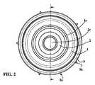
完全な組立て後、人工の寛骨臼は、図1乃至3に例示されるようである。人工の寛骨臼は、関節インサート1と、球形ヘッド2と、挿入カップ3とを含む。 After complete assembly, the artificial acetabulum appears to be illustrated in FIGS. The artificial acetabulum includes a
挿入カップ3は、金属製である。挿入カップ3は、凸状の外側固定面3aを有し、外側固定面3aは、実質的に半球形であり、患者の骨盤内の杯状窩(cotyloid cavity)内に固定されるよう設計される。図1及び2中により明瞭に見ることができるように、外側固定面3aは、骨盤の杯状窩内でのその固定を容易化する突起3bを有利に有する。挿入カップ3は、球形の内側収容面3cを有し、内側収容面3cは、関節インサート1を収容する関節表面を構成するよう鏡面磨きされる。関節インサート1は、ポリエチレン又は他の均等なプラスチック材料で作製される。関節インサート1が挿入カップ3内で旋回するのを許容するために、関節インサート1は、挿入カップ3の内側収容面3c内に係入する球形の外側面1aを有する。関節インサート1は、収容面1bを有し、実質的に半球形の凹状の関節表面1dを備える関節腔1cが収容面1b内に開口している。 The insertion cup 3 is made of metal. The insertion cup 3 has a convex
球形ヘッド2は、関節インサート1の関節腔1c内に係入され、球形ヘッド2は、矢印4によって例示される引抜き力の効果の下のその軸方向解放に抗する保持手段によって、関節腔1c内に保持される。 The
この実施態様において、保持手段は、関節インサート1自体によって形成され、関節インサート1は、この目的のために、190°よりも大きい角度Aだけ延在する関節表面1dを有する。190°よりも大きい角度Aの値の故に、関節表面1dは、アンダーカット区域10aを有し、アンダーカット区域10aは、収容面1bに向かって狭い。これは関節インサート1の開口の直径D1が球形ヘッド2の直径D2よりも小さく、従って、高い値より上の引抜き力4の効果の下でのみ球形ヘッド2を関節腔1cから解放し得るという結果を有する。 In this embodiment, the holding means is formed by the
球形ヘッド2は、球形の外側関節表面2aを有し、よって、外側関節表面2aは、角度Aだけ延在し、半球よりも大きい球形キャップ2bに亘って関節腔1c内に係入される。 The
球形ヘッド2をセラミック又は金属で作製し得る。コストの観点から、金属が好ましい。金属は、例えば、ステンレス鋼又はチタンであり得る。同じことが挿入カップ3にも当て嵌まる。 The
球形ヘッド2は、力を伴って股関節人工器官の第一部分のネック端部を収容する切頭円錐形の凹部2cを有する。 The
図4乃至6は、寛骨臼の他の素子から隔離された球形ヘッド2の構造をより明らかに示している。同じ素子は、図1乃至3におけると同じ参照番号によって示されている。 4 to 6 more clearly show the structure of the
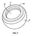
図7乃至9は、寛骨臼の他の素子から隔離された関節インサート1の構造をより明らかに示している。同じ素子は、図1乃至3におけると同じ参照番号によって示されている。 7 to 9 more clearly show the structure of the
図9は、関節表面1dと、線OX及びOYによって示されるコーンによって制限される球形キャップ2bに対応する関節表面の部分とをより明らかに示しており、コーンの頂点は、球形ヘッド2及び関節表面1dの中心Oにある。この球形キャップ2bは半球よりも大きく、角度A又は図3において球形ヘッド2が関節インサート内に係入される角度だけ延在している。コーンOX−OYとの交点に対して直角に、関節表面1dの後には直径D1の円錐形区画1eが続き、次に、収容面1bと接合する斜縁部が続く。 FIG. 9 more clearly shows the
本発明によれば、関節インサート1及び球形ヘッド2は工場で組み立てられ、次に、図10乃至12に例示されるように、殺菌されて防護外被5内に包装される。挿入カップ3は、別個に包装される。 In accordance with the present invention, the
寛骨臼を使用するために、開業医は、治療されるべき患者に形成される杯状窩の形態に適した挿入カップ3を選択し、関節インサート1と、球形ヘッド2であって、その凹部2cが治療されるべき患者の解剖学的特徴の機能に応じて人工器官の第一部分の長さを調節するのに適した球形ヘッド2とを選択し、患者の骨盤内に形成される杯状窩内に挿入カップ3を配置し、そして、球形ヘッド2を関節インサート1内に力で嵌入させる必要を伴わずに、股関節人工器官の他の素子を組み立てる。 In order to use the acetabulum, the practitioner selects an insertion cup 3 suitable for the cup-shaped configuration formed in the patient to be treated, the
図13乃至15に例示されるような本発明の人工股関節寛骨臼の第二実施態様を今や記載する。 A second embodiment of the hip acetabulum of the present invention as illustrated in FIGS. 13-15 will now be described.
この実施態様も、球形ヘッド2を収容し且つ保持する関節インサート1を有する。関節インサート1は、回転を伴って中間インサート6内に係入され、中間インサート6自体は、挿入カップ3内に固定的に係入される。 This embodiment also has a
この実施態様では、球形ヘッド2、関節インサート1、及び、中間インサート6をセラミックで作製し得る。挿入カップ3は、金属、例えば、ステンレス鋼又はチタン製である。 In this embodiment, the
球形ヘッド2は、図1乃至12における実施態様中のヘッド2と同じ形状を有する。 The
関節インサート1が関節表面1dと、関節腔1cと、球形ヘッド2を係入する収容面1bと、球形の外側表面1aとを再び有する点で、関節インサート1は、図1乃至12中の先行する実施態様中の関節インサートに類似する。 The
この第二実施態様における相違は、本質的には、保持手段の構造にある。 The difference in this second embodiment is essentially the structure of the holding means.
この場合、保持手段は、連続的な環状リング10bを含み、連続的な環状リング10bは、球形ヘッド2に対して遊び10dを伴って機能的に係合し得る球冠の形状の保持表面10cを有し、関節インサート1の対応する凹部1fと機能的にインターロックし得る周辺的な固定突起10eを有する。 In this case, the holding means comprises a continuous
実際には、連続的な環状リング10bは、関節インサート1の関節腔1cの入口に形成される対応する形状の座内に係入される。周辺突起10eは、例えば、連続的な環状リング10bの周辺リブを含み、周辺リブは、関節インサート1の対応する環状溝内に係入する。連続的な環状リング10bが関節インサート1内に配置されるとき、その保持表面10cは、球形ヘッド2を関節インサート1の関節腔1cの内側に保持するアンダーカット区域を構成する。 In practice, the continuous
図1乃至12中の実施態様におけるように、人工器官が移植されるとき、開業医が球形ヘッド2を力で関節インサート1内に嵌入する必要がないよう、関節インサート1及び球形ヘッド2は、連続的な環状リング10bを所定位置に備えた状態で、防護外被内で組み立てられ且つ殺菌された状態で出荷される。 As in the embodiment in FIGS. 1-12, the
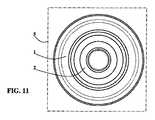
図16乃至18に例示されるような本発明に従った人工器官股関節寛骨臼の第三実施態様を今や記載する。この実施態様も、先行する実施態様におけるヘッドと同じ球形ヘッド2と、関節インサート1と、カップ3とを有する。第一の相違は、患者の杯状窩内に係入し且つ旋回し得る摺動表面を構成するために、カップ3が可動カップであり、その外側面3aが球形であり且つ滑らかであるという事実にある。 A third embodiment of a prosthetic hip acetabulum according to the present invention as illustrated in FIGS. 16-18 will now be described. This embodiment also has the same
この実施態様において、関節インサート1の関節表面1dは、半球形である。関節インサート1は、ポリエチレン又は他の均等なプラスチック材で作製され、カップ3内に固定的に係入される。再び、保持手段は、図13乃至15中の実施態様における環状リングと類似する連続的な環状リング10bであり、球形ヘッド2に対して遊び10dを伴って機能的に係合し得る球冠の形状の保持表面10cを備え、周辺固定突起10eを有する。 In this embodiment, the
この場合、周辺突起10eは、カップ3の腔内に形成される凹部3f内にある。よって、連続的な環状リング10bは、カップ3によって保持される。球冠の形状のその保持表面10cは、関節表面1dのアンダーカット区域を構成し、それは関節インサート1からの球形ヘッド2の引き抜きに抗する。 In this case, the
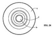
図19乃至21は、本発明に従った人工器官股関節寛骨臼の第四実施態様を例示している。再び、この実施態様は、先行する実施態様における球形ヘッドと同じ球形ヘッド2を有する。関節インサート1はセラミック製であり、実質的に半球形の関節表面1dを有する。患者の骨盤内の杯状窩内で旋回し得る関節表面を構成するよう、セラミック製の関節インサート1の外表面1aは球形である。 Figures 19 to 21 illustrate a fourth embodiment of a prosthetic hip acetabulum according to the present invention. Again, this embodiment has the same
この実施態様において、保持手段は、再び、ポリエチレン又は他の均等なプラスチック材料で作製される連続的な環状リング10bによって形成され、関節表面1dのアンダーカット区域を構成する球冠の形状の保持表面10cを備え、関節インサート1の対応する凹部1fと機能的に係止する周辺固定突起を備える。このようにして、セラミック製の可動カップを備える寛骨臼が得られる。 In this embodiment, the retaining means is again formed by a continuous
図22は、斜視図において、環状リング10bの連続性を例示しており、環状リング10bは、図13乃至21中の実施態様において使用されるリングに類似している。 FIG. 22 illustrates the continuity of the
既述の全ての実施態様において、保持手段は、ポリエチレン又は均等なプラスチック材料で作製される構成部品であり、球形ヘッド2を関節インサート1内に嵌入するとき、この構成部品は変形されなければならない。例えば、ポリエチレン、ポリエーテルエーテルケトン(PEEK)等を使用することが可能である。 In all the previously described embodiments, the holding means is a component made of polyethylene or an equivalent plastic material, which must be deformed when the
関節インサート1を拡張し、それによって、球形ヘッド2の挿入を容易化するために、図1乃至3中の実施態様では、関節インサート1の口を変形することが必要である。 In order to expand the
他の実施態様では、関節インサート1又は周辺カップ3内への連続的な環状リングの係入を容易化するために、連続的な環状リング10bを収縮することが必要である。 In other embodiments, it is necessary to retract the continuous
この目的のために、保持手段は示差熱応力(differential thermal stress)に晒され、それは保持手段の寸法を一時的に変更し、よって、その組立てを容易化する。組立て後、保持手段は室温に戻ることが許容され、保持手段はその元の形状を回復し、次に、関節インサート1からの球形ヘッド2の引き抜きに抗する。 For this purpose, the holding means are subjected to differential thermal stress, which temporarily changes the dimensions of the holding means and thus facilitates its assembly. After assembly, the holding means is allowed to return to room temperature, the holding means recovers its original shape and then resists withdrawal of the
関節インサート1自体が保持手段10aを構成し且つポリエチレンで作成される図1乃至3中の実施態様において、その内径を一時的に増大し、それによって、球形ヘッド2の軸方向の導入を容易化するために、示差熱応力は関節インサート1の加熱に存する。 In the embodiment in FIGS. 1 to 3 where the
連続的な環状リング10bの形態の保持手段の場合、その外径を一時的に減少し、それによって、関節インサート1又は周辺カップ3のそれぞれの対応する凹部1f又は3f内へのリングの周辺突起10eの係合を促進するために、示差熱応力は、連続的な環状リング10bの冷却に存する。 In the case of a holding means in the form of a continuous
本発明によれば、上記に定められるような組立てステップは、球形ヘッド2と関節インサート1とから成るユニットの殺菌のステップの前に行われる。 According to the invention, the assembly step as defined above takes place before the step of sterilization of the unit consisting of the
殺菌ステップは、ガンマ線の照射による殺菌のステップを含み得る。 The sterilization step may include a sterilization step by gamma irradiation.
本発明によれば、殺菌前の組立体は、関節インサート内の球形ヘッドの保持能力が実質的に増大されることを可能にし、それが脱臼の危険性を低減することが分かった。 In accordance with the present invention, it has been found that the assembly prior to sterilization allows the holding capacity of the spherical head within the joint insert to be substantially increased, which reduces the risk of dislocation.
この保持能力の増大は、以下の条件の下で、関節インサート内に係入されるヘッドに対して比較牽引試験を実行することによって実証された。
− 28mmの寸法のステンレス鋼から成るヘッド。
− 4mmの長さのアンダーカット保持区域と、48、54又は62mmの外径を備える、ポリエチレンから成る関節インサート。
− ヘッドと関節インサートとの間に加えられる軸方向の牽引力。This increase in retention capability was demonstrated by performing a comparative traction test on a head that was anchored in the joint insert under the following conditions.
A head made of stainless steel with dimensions of 28 mm;
A joint insert made of polyethylene with an undercut holding area of 4 mm length and an outer diameter of 48, 54 or 62 mm.
-The axial traction force applied between the head and the joint insert.
以下の表は、殺菌後に関節インサート内に導入されたヘッド又は殺菌前に関節インサート内に導入されたヘッドの2つの場合の各々における、関節インサートの3つの外径に関する、関節インサートからの球形ヘッドの解放をもたらす力の限界値を示している。 The following table shows the spherical head from the joint insert for each of the three outer diameters of the joint insert in each of the two cases: the head introduced into the joint insert after sterilization or the head introduced into the joint insert before sterilization. The limit value of the force that brings about the release of.

本発明は明示的に記載した実施態様に限定されず、その代わり、本発明は付属の請求項の範囲内に含められる様々な変更及び一般化を含む。 The invention is not limited to the explicitly described embodiments, but instead the invention includes various modifications and generalizations included within the scope of the appended claims.
Claims (12)
Translated fromJapanese該関節インサートの前記関節腔内に係入し得る球形ヘッドと、
前記球形ヘッドが前記関節腔内に係入されるときに前記関節インサートの前記関節腔からの前記球形ヘッドの軸方向の解放に抗する保持手段とを含み、
前記関節インサート及び前記球形ヘッドから成る組立体が殺菌状態において防護外被内に包装され、
前記防護外被内で、前記球形ヘッドは、前記関節インサートの前記関節腔内に係入され、前記保持手段によって保持されることを特徴とする、
人工股関節寛骨臼。A joint insert comprising a receiving surface, wherein a joint cavity comprising a substantially hemispherical concave articulating surface opens into the receiving surface;
A spherical head that can be inserted into the joint cavity of the joint insert;
Holding means for resisting axial release of the spherical head from the joint cavity of the joint insert when the spherical head is engaged in the joint cavity;
The assembly comprising the joint insert and the spherical head is packaged in a protective jacket in a sterilized condition;
Within the protective jacket, the spherical head is engaged in the joint cavity of the joint insert and is held by the holding means,
Artificial hip acetabulum.
Applications Claiming Priority (3)
| Application Number | Priority Date | Filing Date | Title |
|---|---|---|---|
| FR0957130AFR2951071B1 (en) | 2009-10-12 | 2009-10-12 | PROTHETIC COTYLE WITH LARGE RETENTION CAPACITY |
| FR0957130 | 2009-10-12 | ||
| PCT/IB2010/054603WO2011045737A2 (en) | 2009-10-12 | 2010-10-12 | Acetabular cup with high retention capacity |
Publications (2)
| Publication Number | Publication Date |
|---|---|
| JP2013507166Atrue JP2013507166A (en) | 2013-03-04 |
| JP5758392B2 JP5758392B2 (en) | 2015-08-05 |
Family
ID=42307935
Family Applications (1)
| Application Number | Title | Priority Date | Filing Date |
|---|---|---|---|
| JP2012532710AActiveJP5758392B2 (en) | 2009-10-12 | 2010-10-12 | Acetabular cup with high holding ability |
Country Status (8)
| Country | Link |
|---|---|
| US (1) | US8882849B2 (en) |
| EP (1) | EP2488128B1 (en) |
| JP (1) | JP5758392B2 (en) |
| CN (1) | CN102596106B (en) |
| CA (1) | CA2776736C (en) |
| ES (1) | ES2436640T3 (en) |
| FR (1) | FR2951071B1 (en) |
| WO (1) | WO2011045737A2 (en) |
Families Citing this family (13)
| Publication number | Priority date | Publication date | Assignee | Title |
|---|---|---|---|---|
| DE102008045291B4 (en) | 2008-09-02 | 2013-05-02 | Merete Medical Gmbh | Knee arthrodesis implant |
| DE202010008828U1 (en)* | 2010-10-18 | 2010-12-09 | Merete Medical Gmbh | Modular joint prosthesis system |
| CN103211668A (en)* | 2012-01-20 | 2013-07-24 | 北京市春立正达医疗器械股份有限公司 | Bipolar head prosthesis |
| WO2014052768A2 (en) | 2012-09-27 | 2014-04-03 | The Regeneral Hospital Corporation D/B/A Massachusetts General Hospital | Femoral heads, mobile inserts, acetabular components, and modular junctions for orthopedic implants and methods of using femoral heads, mobile inserts, acetabular components, and modular junctions for orthopedic implants |
| US20150025647A1 (en)* | 2013-07-16 | 2015-01-22 | Howmedica Osteonics Corp. | Dual mobility hip replacement system |
| EP3050539A1 (en)* | 2015-01-27 | 2016-08-03 | AQ Implants GmbH | Revision endoprosthesis |
| CN105030380A (en)* | 2015-05-15 | 2015-11-11 | 江苏奥康尼医疗科技发展有限公司 | Combined artificial hip joint cup |
| DE102016114368B3 (en)* | 2016-08-03 | 2017-11-16 | Aesculap Ag | Socket and joint endoprosthesis |
| JP7189134B2 (en) | 2016-10-17 | 2022-12-13 | スミス アンド ネフュー インコーポレイテッド | Lateral dual mobility assembly |
| AU2018200701B2 (en) | 2017-02-02 | 2023-07-27 | Howmedica Osteonics Corp. | Constrained shell for modular dual mobility system |
| US12083018B2 (en) | 2020-09-18 | 2024-09-10 | Globus Medical, Inc. | Hip arthroplasty implants |
| US12053383B2 (en) | 2020-09-18 | 2024-08-06 | Globus Medical Inc. | Hip arthroplasty implants |
| CN112318548B (en)* | 2020-11-18 | 2024-06-14 | 杭州华匠医学机器人有限公司 | Mechanical arm |
Citations (3)
| Publication number | Priority date | Publication date | Assignee | Title |
|---|---|---|---|---|
| JP2000503871A (en)* | 1996-02-02 | 2000-04-04 | ヴォアデヴィル,ジル | Non-dislocated low-wear lumbar prosthesis |
| JP2005538778A (en)* | 2002-09-13 | 2005-12-22 | スミス アンド ネフュー インコーポレーテッド | Prosthesis |
| JP2006511272A (en)* | 2002-12-18 | 2006-04-06 | スミス アンド ネフュー インコーポレーテッド | Bidirectional hip prosthesis device using diffusion hardened surface |
Family Cites Families (8)
| Publication number | Priority date | Publication date | Assignee | Title |
|---|---|---|---|---|
| US4676798A (en)* | 1984-09-12 | 1987-06-30 | Joint Medical Products Corporation | Socket bearing assembly for a constrained ball and socket joint |
| NL8700879A (en)* | 1987-04-14 | 1988-11-01 | Jan Bernard Mullers | JOINT PROSTHESIS AND JOINT PROSTHESIS ORGANIZATION AND COMBINED ELEMENT FOR APPLICATION IN SUCH A JOINT PROSTHESIS ORGANIZATION. |
| DE4102510C2 (en)* | 1991-01-29 | 2003-06-18 | Peter Brehm | hip prosthesis |
| US20030060890A1 (en)* | 2001-09-24 | 2003-03-27 | Tarabishy Imad Ed. | Joint prosthesis and method for implantation |
| GB0321582D0 (en)* | 2003-09-15 | 2003-10-15 | Benoist Girard Sas | Prosthetic acetabular cup and prosthetic femoral joint incorporating such a cup |
| FR2876278B1 (en)* | 2004-10-13 | 2007-10-26 | Thomas Gradel | COTYL APPLICATION INSTRUMENTS |
| EP2094197B8 (en)* | 2006-12-07 | 2016-03-09 | IHip Surgical, LLC | Apparatus for total hip replacement |
| GB2447702A (en)* | 2007-03-23 | 2008-09-24 | Univ Leeds | Surgical bone cutting template |
- 2009
- 2009-10-12FRFR0957130Apatent/FR2951071B1/ennot_activeExpired - Fee Related
- 2010
- 2010-10-12CNCN201080045911.6Apatent/CN102596106B/ennot_activeExpired - Fee Related
- 2010-10-12ESES10785518.1Tpatent/ES2436640T3/enactiveActive
- 2010-10-12USUS13/500,927patent/US8882849B2/enactiveActive
- 2010-10-12WOPCT/IB2010/054603patent/WO2011045737A2/enactiveApplication Filing
- 2010-10-12JPJP2012532710Apatent/JP5758392B2/enactiveActive
- 2010-10-12CACA2776736Apatent/CA2776736C/enactiveActive
- 2010-10-12EPEP10785518.1Apatent/EP2488128B1/enactiveActive
Patent Citations (3)
| Publication number | Priority date | Publication date | Assignee | Title |
|---|---|---|---|---|
| JP2000503871A (en)* | 1996-02-02 | 2000-04-04 | ヴォアデヴィル,ジル | Non-dislocated low-wear lumbar prosthesis |
| JP2005538778A (en)* | 2002-09-13 | 2005-12-22 | スミス アンド ネフュー インコーポレーテッド | Prosthesis |
| JP2006511272A (en)* | 2002-12-18 | 2006-04-06 | スミス アンド ネフュー インコーポレーテッド | Bidirectional hip prosthesis device using diffusion hardened surface |
Also Published As
| Publication number | Publication date |
|---|---|
| US20120197412A1 (en) | 2012-08-02 |
| EP2488128B1 (en) | 2013-09-04 |
| ES2436640T3 (en) | 2014-01-03 |
| CN102596106B (en) | 2015-05-06 |
| FR2951071A1 (en) | 2011-04-15 |
| FR2951071B1 (en) | 2011-10-28 |
| CA2776736C (en) | 2016-08-16 |
| EP2488128A2 (en) | 2012-08-22 |
| CN102596106A (en) | 2012-07-18 |
| WO2011045737A2 (en) | 2011-04-21 |
| CA2776736A1 (en) | 2011-04-21 |
| US8882849B2 (en) | 2014-11-11 |
| WO2011045737A3 (en) | 2011-06-09 |
| JP5758392B2 (en) | 2015-08-05 |
Similar Documents
| Publication | Publication Date | Title |
|---|---|---|
| JP5758392B2 (en) | Acetabular cup with high holding ability | |
| JP5671106B2 (en) | Method for manufacturing an artificial acetabular external assembly | |
| US6916342B2 (en) | Liner assembly for prosthetic components | |
| US4936855A (en) | Stepped-lock ring system for implantable joint prostheses | |
| JP5769320B2 (en) | Interlocking reverse hip joint and revision prosthesis | |
| EP1506749B1 (en) | Constrained acetabular liner | |
| JP4204691B2 (en) | Bipolar hip prosthesis with lock head | |
| EP1293179A1 (en) | Resilient thimble for ball head of prosthetic joint | |
| EP1900344A2 (en) | Resurfacing femoral head component | |
| JP4243060B2 (en) | Tool for adjusting the mutual angle between the parts of the hip prosthesis | |
| EP2911615B9 (en) | Acetabular prosthesis and corresponding method for production and assembly | |
| US9351838B2 (en) | Deformable prosthesis | |
| HK1178419B (en) | Interlocking reverse hip and revision prosthesis |
Legal Events
| Date | Code | Title | Description |
|---|---|---|---|
| A621 | Written request for application examination | Free format text:JAPANESE INTERMEDIATE CODE: A621 Effective date:20130723 | |
| A977 | Report on retrieval | Free format text:JAPANESE INTERMEDIATE CODE: A971007 Effective date:20140327 | |
| A131 | Notification of reasons for refusal | Free format text:JAPANESE INTERMEDIATE CODE: A131 Effective date:20140408 | |
| A601 | Written request for extension of time | Free format text:JAPANESE INTERMEDIATE CODE: A601 Effective date:20140530 | |
| A602 | Written permission of extension of time | Free format text:JAPANESE INTERMEDIATE CODE: A602 Effective date:20140606 | |
| A521 | Request for written amendment filed | Free format text:JAPANESE INTERMEDIATE CODE: A523 Effective date:20140807 | |
| A02 | Decision of refusal | Free format text:JAPANESE INTERMEDIATE CODE: A02 Effective date:20141104 | |
| A711 | Notification of change in applicant | Free format text:JAPANESE INTERMEDIATE CODE: A711 Effective date:20150123 | |
| A521 | Request for written amendment filed | Free format text:JAPANESE INTERMEDIATE CODE: A523 Effective date:20150226 | |
| A911 | Transfer to examiner for re-examination before appeal (zenchi) | Free format text:JAPANESE INTERMEDIATE CODE: A911 Effective date:20150306 | |
| TRDD | Decision of grant or rejection written | ||
| A01 | Written decision to grant a patent or to grant a registration (utility model) | Free format text:JAPANESE INTERMEDIATE CODE: A01 Effective date:20150512 | |
| A61 | First payment of annual fees (during grant procedure) | Free format text:JAPANESE INTERMEDIATE CODE: A61 Effective date:20150603 | |
| R150 | Certificate of patent or registration of utility model | Ref document number:5758392 Country of ref document:JP Free format text:JAPANESE INTERMEDIATE CODE: R150 | |
| R250 | Receipt of annual fees | Free format text:JAPANESE INTERMEDIATE CODE: R250 | |
| R250 | Receipt of annual fees | Free format text:JAPANESE INTERMEDIATE CODE: R250 | |
| R250 | Receipt of annual fees | Free format text:JAPANESE INTERMEDIATE CODE: R250 | |
| R250 | Receipt of annual fees | Free format text:JAPANESE INTERMEDIATE CODE: R250 | |
| R250 | Receipt of annual fees | Free format text:JAPANESE INTERMEDIATE CODE: R250 | |
| R250 | Receipt of annual fees | Free format text:JAPANESE INTERMEDIATE CODE: R250 | |
| R250 | Receipt of annual fees | Free format text:JAPANESE INTERMEDIATE CODE: R250 | |
| R250 | Receipt of annual fees | Free format text:JAPANESE INTERMEDIATE CODE: R250 |