JP2013502978A - Medical device and method - Google Patents
Medical device and methodDownload PDFInfo
- Publication number
- JP2013502978A JP2013502978AJP2012526736AJP2012526736AJP2013502978AJP 2013502978 AJP2013502978 AJP 2013502978AJP 2012526736 AJP2012526736 AJP 2012526736AJP 2012526736 AJP2012526736 AJP 2012526736AJP 2013502978 AJP2013502978 AJP 2013502978A
- Authority
- JP
- Japan
- Prior art keywords
- data
- electronic device
- certain embodiments
- worn electronic
- display device
- Prior art date
- Legal status (The legal status is an assumption and is not a legal conclusion. Google has not performed a legal analysis and makes no representation as to the accuracy of the status listed.)
- Granted
Links
- 0CCC1*CCC(C)C1Chemical compoundCCC1*CCC(C)C10.000description2
Images


Classifications
- G—PHYSICS
- G16—INFORMATION AND COMMUNICATION TECHNOLOGY [ICT] SPECIALLY ADAPTED FOR SPECIFIC APPLICATION FIELDS
- G16H—HEALTHCARE INFORMATICS, i.e. INFORMATION AND COMMUNICATION TECHNOLOGY [ICT] SPECIALLY ADAPTED FOR THE HANDLING OR PROCESSING OF MEDICAL OR HEALTHCARE DATA
- G16H40/00—ICT specially adapted for the management or administration of healthcare resources or facilities; ICT specially adapted for the management or operation of medical equipment or devices
- G16H40/60—ICT specially adapted for the management or administration of healthcare resources or facilities; ICT specially adapted for the management or operation of medical equipment or devices for the operation of medical equipment or devices
- G16H40/67—ICT specially adapted for the management or administration of healthcare resources or facilities; ICT specially adapted for the management or operation of medical equipment or devices for the operation of medical equipment or devices for remote operation
- A—HUMAN NECESSITIES
- A61—MEDICAL OR VETERINARY SCIENCE; HYGIENE
- A61B—DIAGNOSIS; SURGERY; IDENTIFICATION
- A61B5/00—Measuring for diagnostic purposes; Identification of persons
- A61B5/0002—Remote monitoring of patients using telemetry, e.g. transmission of vital signals via a communication network
- A61B5/0015—Remote monitoring of patients using telemetry, e.g. transmission of vital signals via a communication network characterised by features of the telemetry system
- A61B5/0017—Remote monitoring of patients using telemetry, e.g. transmission of vital signals via a communication network characterised by features of the telemetry system transmitting optical signals
- A—HUMAN NECESSITIES
- A61—MEDICAL OR VETERINARY SCIENCE; HYGIENE
- A61B—DIAGNOSIS; SURGERY; IDENTIFICATION
- A61B5/00—Measuring for diagnostic purposes; Identification of persons
- A61B5/0002—Remote monitoring of patients using telemetry, e.g. transmission of vital signals via a communication network
- A61B5/0015—Remote monitoring of patients using telemetry, e.g. transmission of vital signals via a communication network characterised by features of the telemetry system
- A61B5/0022—Monitoring a patient using a global network, e.g. telephone networks, internet
- A—HUMAN NECESSITIES
- A61—MEDICAL OR VETERINARY SCIENCE; HYGIENE
- A61B—DIAGNOSIS; SURGERY; IDENTIFICATION
- A61B5/00—Measuring for diagnostic purposes; Identification of persons
- A61B5/01—Measuring temperature of body parts ; Diagnostic temperature sensing, e.g. for malignant or inflamed tissue
- A—HUMAN NECESSITIES
- A61—MEDICAL OR VETERINARY SCIENCE; HYGIENE
- A61B—DIAGNOSIS; SURGERY; IDENTIFICATION
- A61B5/00—Measuring for diagnostic purposes; Identification of persons
- A61B5/145—Measuring characteristics of blood in vivo, e.g. gas concentration or pH-value ; Measuring characteristics of body fluids or tissues, e.g. interstitial fluid or cerebral tissue
- A61B5/14532—Measuring characteristics of blood in vivo, e.g. gas concentration or pH-value ; Measuring characteristics of body fluids or tissues, e.g. interstitial fluid or cerebral tissue for measuring glucose, e.g. by tissue impedance measurement
- A—HUMAN NECESSITIES
- A61—MEDICAL OR VETERINARY SCIENCE; HYGIENE
- A61B—DIAGNOSIS; SURGERY; IDENTIFICATION
- A61B5/00—Measuring for diagnostic purposes; Identification of persons
- A61B5/145—Measuring characteristics of blood in vivo, e.g. gas concentration or pH-value ; Measuring characteristics of body fluids or tissues, e.g. interstitial fluid or cerebral tissue
- A61B5/1468—Measuring characteristics of blood in vivo, e.g. gas concentration or pH-value ; Measuring characteristics of body fluids or tissues, e.g. interstitial fluid or cerebral tissue using chemical or electrochemical methods, e.g. by polarographic means
- A61B5/1486—Measuring characteristics of blood in vivo, e.g. gas concentration or pH-value ; Measuring characteristics of body fluids or tissues, e.g. interstitial fluid or cerebral tissue using chemical or electrochemical methods, e.g. by polarographic means using enzyme electrodes, e.g. with immobilised oxidase
- A—HUMAN NECESSITIES
- A61—MEDICAL OR VETERINARY SCIENCE; HYGIENE
- A61B—DIAGNOSIS; SURGERY; IDENTIFICATION
- A61B5/00—Measuring for diagnostic purposes; Identification of persons
- A61B5/72—Signal processing specially adapted for physiological signals or for diagnostic purposes
- G—PHYSICS
- G01—MEASURING; TESTING
- G01N—INVESTIGATING OR ANALYSING MATERIALS BY DETERMINING THEIR CHEMICAL OR PHYSICAL PROPERTIES
- G01N33/00—Investigating or analysing materials by specific methods not covered by groups G01N1/00 - G01N31/00
- G01N33/48—Biological material, e.g. blood, urine; Haemocytometers
- G01N33/483—Physical analysis of biological material
- G01N33/487—Physical analysis of biological material of liquid biological material
- G01N33/48785—Electrical and electronic details of measuring devices for physical analysis of liquid biological material not specific to a particular test method, e.g. user interface or power supply
- G01N33/48792—Data management, e.g. communication with processing unit
- G—PHYSICS
- G06—COMPUTING OR CALCULATING; COUNTING
- G06Q—INFORMATION AND COMMUNICATION TECHNOLOGY [ICT] SPECIALLY ADAPTED FOR ADMINISTRATIVE, COMMERCIAL, FINANCIAL, MANAGERIAL OR SUPERVISORY PURPOSES; SYSTEMS OR METHODS SPECIALLY ADAPTED FOR ADMINISTRATIVE, COMMERCIAL, FINANCIAL, MANAGERIAL OR SUPERVISORY PURPOSES, NOT OTHERWISE PROVIDED FOR
- G06Q50/00—Information and communication technology [ICT] specially adapted for implementation of business processes of specific business sectors, e.g. utilities or tourism
- G06Q50/10—Services
- G06Q50/22—Social work or social welfare, e.g. community support activities or counselling services
- G—PHYSICS
- G16—INFORMATION AND COMMUNICATION TECHNOLOGY [ICT] SPECIALLY ADAPTED FOR SPECIFIC APPLICATION FIELDS
- G16H—HEALTHCARE INFORMATICS, i.e. INFORMATION AND COMMUNICATION TECHNOLOGY [ICT] SPECIALLY ADAPTED FOR THE HANDLING OR PROCESSING OF MEDICAL OR HEALTHCARE DATA
- G16H40/00—ICT specially adapted for the management or administration of healthcare resources or facilities; ICT specially adapted for the management or operation of medical equipment or devices
- G16H40/60—ICT specially adapted for the management or administration of healthcare resources or facilities; ICT specially adapted for the management or operation of medical equipment or devices for the operation of medical equipment or devices
- G16H40/63—ICT specially adapted for the management or administration of healthcare resources or facilities; ICT specially adapted for the management or operation of medical equipment or devices for the operation of medical equipment or devices for local operation
- A—HUMAN NECESSITIES
- A61—MEDICAL OR VETERINARY SCIENCE; HYGIENE
- A61B—DIAGNOSIS; SURGERY; IDENTIFICATION
- A61B2560/00—Constructional details of operational features of apparatus; Accessories for medical measuring apparatus
- A61B2560/02—Operational features
- A61B2560/0223—Operational features of calibration, e.g. protocols for calibrating sensors
- A61B2560/0238—Means for recording calibration data
- Y—GENERAL TAGGING OF NEW TECHNOLOGICAL DEVELOPMENTS; GENERAL TAGGING OF CROSS-SECTIONAL TECHNOLOGIES SPANNING OVER SEVERAL SECTIONS OF THE IPC; TECHNICAL SUBJECTS COVERED BY FORMER USPC CROSS-REFERENCE ART COLLECTIONS [XRACs] AND DIGESTS
- Y02—TECHNOLOGIES OR APPLICATIONS FOR MITIGATION OR ADAPTATION AGAINST CLIMATE CHANGE
- Y02A—TECHNOLOGIES FOR ADAPTATION TO CLIMATE CHANGE
- Y02A90/00—Technologies having an indirect contribution to adaptation to climate change
- Y02A90/10—Information and communication technologies [ICT] supporting adaptation to climate change, e.g. for weather forecasting or climate simulation
Landscapes
- Health & Medical Sciences (AREA)
- Life Sciences & Earth Sciences (AREA)
- Engineering & Computer Science (AREA)
- Physics & Mathematics (AREA)
- Biomedical Technology (AREA)
- General Health & Medical Sciences (AREA)
- Medical Informatics (AREA)
- Biophysics (AREA)
- Public Health (AREA)
- Molecular Biology (AREA)
- Pathology (AREA)
- Heart & Thoracic Surgery (AREA)
- Surgery (AREA)
- Animal Behavior & Ethology (AREA)
- Veterinary Medicine (AREA)
- Chemical & Material Sciences (AREA)
- Optics & Photonics (AREA)
- Business, Economics & Management (AREA)
- Computer Networks & Wireless Communication (AREA)
- Primary Health Care (AREA)
- General Business, Economics & Management (AREA)
- General Physics & Mathematics (AREA)
- Epidemiology (AREA)
- Medicinal Chemistry (AREA)
- Human Computer Interaction (AREA)
- Analytical Chemistry (AREA)
- Biochemistry (AREA)
- Urology & Nephrology (AREA)
- Immunology (AREA)
- Hematology (AREA)
- Food Science & Technology (AREA)
- Databases & Information Systems (AREA)
- Chemical Kinetics & Catalysis (AREA)
- General Chemical & Material Sciences (AREA)
- Emergency Medicine (AREA)
- Computer Vision & Pattern Recognition (AREA)
- Artificial Intelligence (AREA)
- Signal Processing (AREA)
- Psychiatry (AREA)
- Physiology (AREA)
Abstract
Translated fromJapaneseDescription
Translated fromJapanese本願は、2009年8月31に出願された米国特許仮出願第61/238,581号明細書、2009年9月30日に出願された米国特許仮出願第61/247,519号明細書、2009年9月30日に出願された米国特許仮出願第61/247,514号明細書、2009年9月30日に出願された米国特許仮出願第61/247,508号明細書、2009年10月30日に出願された米国特許仮出願第61/256,925号明細書、2009年12月30日に出願された米国特許仮出願第61/291,326号明細書、および2010年1月29日に出願された米国特許仮出願第61/299,924号明細書による利益を主張し、それぞれの開示をあらゆる目的で参照して本明細書に組み込む。 The present application is based on US provisional application 61 / 238,581 filed on August 31, 2009, US provisional application 61 / 247,519 filed on September 30, 2009, US Provisional Application No. 61 / 247,514 filed on September 30, 2009, US Provisional Patent Application No. 61 / 247,508 filed on September 30, 2009, 2009 US Provisional Application No. 61 / 256,925 filed on October 30, US Provisional Patent Application No. 61 / 291,326 filed on December 30, 2009, and 2010 1 Claimed by US provisional application 61 / 299,924, filed on May 29, the disclosures of which are incorporated herein by reference for all purposes.
本明細書に記載される、以下の特許、特許出願および/または特許出願公開を含む特許、特許出願および/または特許出願公開を、あらゆる目的で参照して本明細書に組み込む。米国特許第4,545,382号、同第4,711,245号、同第5,262,035号、同第5,262,305号、同第5,264,104号、同第5,320,715号、同第5,356,786号、同第5,509,410号、同第5,543,326号、同第5,593,852号、同第5,601,435号、同第5,628,890号、同第5,820,551号、同第5,822,715号、同第5,899,855号、同第5,918,603号、同第6,071,391号、同第6,103,033号、同第6,120,676号、同第6,121,009号、同第6,134,461号、同第6,143,164号、同第6,144,837号、同第6,161,095号、同第6,175,752号、同第6,270,455号、同第6,284,478号、同第6,299,757号、同第6,338,790号、同第6,377,894号、同第6,461,496号、同第6,503,381号、同第6,514,460号、同第6,514,718号、同第6,540,891号、同第6,560,471号、同第6,579,690号、同第6,591,125号、同第6,592,745号、同第6,600,997号、同第6,605,200号、同第6,605,201号、同第6,616,819号、同第6,618,934号、同第6,650,471号、同第6,654,625号、同第6,676,816号、同第6,730,200号、同第6,736,957号、同第6,746,582号、同第6,749,740号、同第6,764,581号、同第6,773,671号、同第6,881,551号、同第6,893,545号、同第6,932,892号、同第6,932,894号、同第6,942,518号、同第7,041,468号、同第7,167,818号および同第7,299,082号の各明細書、米国特許出願公開第2004/0186365号、同第2004/0186365号、同第2005/0182306号、同第2006/0025662号、同第2006/0091006号、同第2007/0056858号、同第2007/0068807号、同第2007/0095661号、同第2007/0108048号、同第2007/0199818号、同第2007/0227911号、同第2007/0233013号、同第2008/0066305号、同第2008/0081977号、同第2008/0102441号、同第2008/0148873号、同第2008/0161666号、同第2008/0267823号および同第2009/0054748号の各明細書、米国特許出願第11/461,725号、同第12/131,012号、同第12/393,921号、同第12/242,823号、同第12/363,712号、同第12/495,709号、同第12/698,124号、同第12/698,129号、同第12/714,439号、同第12/794,721号および同第12/842,013号の各明細書、並びに米国特許仮出願第61/238,646号、同第61/246,825号、同第61/247,516号、同第61/249,535号、同第61/317,243号、同第61/345,562号および同第61/361,374号の各明細書。 The patents, patent applications and / or patent application publications described herein, including the following patents, patent applications and / or patent application publications, are incorporated herein by reference for all purposes. U.S. Pat.Nos. 4,545,382, 4,711,245, 5,262,035, 5,262,305, 5,264,104, 5, 320,715, 5,356,786, 5,509,410, 5,543,326, 5,593,852, 5,601,435, 5,628,890, 5,820,551, 5,822,715, 5,899,855, 5,918,603, 6,071 391, 6,103,033, 6,120,676, 6,121,009, 6,134,461, 6,143,164, No. 6,144,837, No. 6,161,095, No. 6,175,752, No. 6,2 No. 0,455, No. 6,284,478, No. 6,299,757, No. 6,338,790, No. 6,377,894, No. 6,461,496, 6,503,381, 6,514,460, 6,514,718, 6,540,891, 6,560,471, 6,579 , 690, 6,591,125, 6,592,745, 6,600,997, 6,605,200, 6,605,201, 6,616,819, 6,618,934, 6,650,471, 6,654,625, 6,676,816, 6,730, No. 200, No. 6,736,957, No. 6,746,582, No. 6,749,740, 6,764,581, 6,773,671, 6,881,551, 6,893,545, 6,932,892, 6,932 No. 894, No. 6,942,518, No. 7,041,468, No. 7,167,818 and No. 7,299,082, U.S. Patent Application Publication No. 2004 / No. 0186365, No. 2004/0186365, No. 2005/0182306, No. 2006/0025662, No. 2006/0091006, No. 2007/0056858, No. 2007/0068807, No. 2007/0095661 No., 2007/0108048, No. 2007/0199818, No. 2007/0227911, No. 2007/0233013 2008/0066305, 2008/0081977, 2008/0102441, 2008/0148873, 2008/0161666, 2008/0267823 and 2009/0054748. No. 11 / 461,725, 12 / 131,012, 12 / 393,921, 12 / 242,823, 12 / 363,712. No. 12, No. 12 / 495,709, No. 12 / 698,124, No. 12 / 698,129, No. 12 / 714,439, No. 12 / 794,721 and No. 12 / 842,013, as well as US provisional applications 61 / 238,646, 61 / 246,825, 61/247, No. 16, Nos. 61 / 249,535, the No. 61 / 317,243, the specifications of the 61 / 345,562 and No. same No. 61 / 361,374.
本発明は、体液中の検体をモニタリングする方法および装置に関し、特に、検体モニタリングシステムにおける双方向通信のための装置に関する。 The present invention relates to a method and apparatus for monitoring a specimen in a body fluid, and more particularly to an apparatus for two-way communication in a specimen monitoring system.
特定の個人のグルコースレベルや、乳酸、酸素、A1C等の他の検体を検出および/またはモニタリングすることは、彼らの健康にとって極めて重要である。例えば、グルコースのモニタリングは、糖尿病の個人にとって特に重要である。糖尿病患者は、一般的に、グルコースレベルをモニタリングして、彼らのグルコースレベルが臨床的に安全な範囲内に維持されいるか否かを判定し、また、この情報を用いて、彼らの体内のグルコースレベルを低減するためにインスリンが必要か否か(および/またはいつ必要か)、または彼らの体内のグルコースレベルを高めるために追加のグルコースが必要か否かを決定し得る。 Detecting and / or monitoring a particular individual's glucose level and other analytes such as lactic acid, oxygen, A1C, etc. is crucial to their health. For example, glucose monitoring is particularly important for diabetic individuals. Diabetics typically monitor glucose levels to determine if their glucose levels are maintained within a clinically safe range and use this information to determine whether glucose in their bodies It may be determined whether insulin is needed (and / or when) to reduce levels, or whether additional glucose is needed to increase glucose levels in their body.
増大する臨床データにより、グルコースモニタリングの頻度と血糖管理とに強い相関があることが示されている。そのような相関にも関わらず、糖尿病の状態を有すると診断された多くの個人は、簡便性、検査の自由裁量、グルコース検査に伴う痛みおよび費用を含む要因の組み合わせにより、グルコースレベルのモニタリングを然るべき頻度で行っていない。 Increasing clinical data indicate that there is a strong correlation between glucose monitoring frequency and glycemic control. Despite such correlations, many individuals diagnosed with a diabetic condition can monitor glucose levels by a combination of factors including convenience, discretion in testing, pain and costs associated with glucose testing. I don't go there often.
血流や間質液(ISF)等の体液や他の生物学的流体中における、グルコース等の検体を自動でモニタリングするための装置が開発されている。このような検体測定装置には、インビボのモニタリングを達成するために、少なくとも装置の一部がユーザの皮膚の表面下(例えば、ユーザの血管や皮下組織内)に配置されるよう構成されたものがある。 Devices have been developed for automatically monitoring analytes such as glucose in body fluids such as blood flow and interstitial fluid (ISF) and other biological fluids. Such an analyte measurement device is configured such that at least a portion of the device is placed below the surface of the user's skin (eg, within the user's blood vessels or subcutaneous tissue) to achieve in vivo monitoring. There is.
検体モニタリング装置およびシステムの継続的な開発と共に、頻繁な検体モニタリングを奨励して血糖管理を向上させるために、コスト効果があって、簡便で、痛みが少なく、配慮のあるモニタリングを提供する検体モニタリング装置、システムおよび方法、並びに、検体モニタリング装置およびシステムの製造方法が必要とされている。 Sample monitoring that provides cost-effective, simple, pain-free and careful monitoring to encourage frequent sample monitoring and improve blood glucose management, along with continued development of sample monitoring devices and systems There is a need for devices, systems and methods, and methods for manufacturing analyte monitoring devices and systems.
主題の開示の複数の実施形態は、インビボ検体モニタリング装置、システム、キット、および検体モニタリング方法、並びに、検体モニタリング装置、システムおよびキットの製造方法を含む。1以上の所定の期間(1以上の所定のモニタリング期間等)にわたって、所望の検体レベル(グルコースレベル等)のリアルタイムの測定/モニタリングを行うよう構成された、身体装着用の(即ち、検体をモニタリングするために、装置、システムまたはその構成要素の少なくとも一部がユーザの身体上に維持される)生理学的モニタリング装置が含まれる。複数の実施形態は、経皮的に配置される検体センサであって、検体センサの使用寿命または所定のモニタリング期間の間に、ユーザの身体(例えば、ユーザの皮膚表面)に装着されるよう設計された筐体内に設けられた電子装置と電気的に接続された検体センサを含む。例えば、身体装着用電子装置アセンブリは、検体センサに動作可能に接続された電子装置であってユーザの身体上に配置される筐体内に設けられた電子装置を含む。 Embodiments of the subject disclosure include in vivo analyte monitoring devices, systems, kits, and analyte monitoring methods, and methods of manufacturing analyte monitoring devices, systems, and kits. Body wearable (ie, monitoring analyte) configured to perform real-time measurement / monitoring of a desired analyte level (such as glucose level) over one or more predetermined periods (such as one or more predetermined monitoring periods). In order to do so, a physiological monitoring device is included (at least a portion of the device, system or component thereof is maintained on the user's body). Embodiments are analyte sensors that are placed percutaneously and are designed to be worn on the user's body (eg, the user's skin surface) during the life of the analyte sensor or a predetermined monitoring period. A specimen sensor electrically connected to an electronic device provided in the case. For example, a body-worn electronic device assembly includes an electronic device operably connected to an analyte sensor and provided within a housing that is disposed on a user's body.
そのような検体センサを有する装置およびシステムは、モニタリング装置またはシステム内のプログラムされたまたはプログラム可能な制御論理またはルーチンによって自動的または半自動的に実行される、連続的または周期的な検体レベルモニタリングを提供する。本明細書において、連続的、自動的および/または周期的モニタリングとは、経皮的に配置された検体センサを用いた、検体レベルのインビボのモニタリングまたは検出を指す。 Devices and systems having such analyte sensors provide continuous or periodic analyte level monitoring that is performed automatically or semi-automatically by programmed or programmable control logic or routines within the monitoring device or system. provide. As used herein, continuous, automatic and / or periodic monitoring refers to analyte level in vivo monitoring or detection using a percutaneously placed analyte sensor.
特定の実施形態では、インビボでモニタリングされた検体レベルの結果が、電子装置ユニットからシステムの別の装置または構成要素に自動的に通信される。即ち、結果が入手可能であるときには、それらの結果が、例えば、システムによって実行される固定的または動的なデータ通信スケジュールに従って、システムの表示装置(またはユーザとやりとりするための他の装置)に自動的に送信される。他の実施形態では、インビボでモニタリングされた検体レベルの結果は、システムの1以上の装置または構成要素に自動的には通信、転送または出力されない。そのような実施形態では、結果は、システムに対するクエリーに応答する場合にのみ提供される。即ち、結果は、そのような結果に対するクエリーまたは要求に応答する場合にのみ、システムの構成要素または装置に通信される。特定の実施形態では、インビボモニタリングの結果は、システムのメモリに記録または格納されて、1以上の所定のモニタリング期間の後にのみ、システムの別の装置または構成要素に通信または転送され得る。 In certain embodiments, analyte level results monitored in vivo are automatically communicated from the electronic device unit to another device or component of the system. That is, when results are available, they can be transferred to the system display (or other device for interacting with the user), eg, according to a fixed or dynamic data communication schedule executed by the system. Automatically sent. In other embodiments, in vivo monitored analyte level results are not automatically communicated, forwarded or output to one or more devices or components of the system. In such embodiments, results are provided only when responding to queries to the system. That is, results are communicated to system components or devices only in response to queries or requests for such results. In certain embodiments, the results of in vivo monitoring can be recorded or stored in the memory of the system and communicated or transferred to another device or component of the system only after one or more predetermined monitoring periods.
複数の実施形態は、装置、構成要素またはシステムの任意の1つを他の装置、構成要素またはシステムの任意の1つに変換するためのソフトウェアおよび/またはハードウェアを含み、そのような変換は、製造後にユーザによって設定可能であり得る。そのような変換を達成するためのハードウェアおよび/またはソフトウェアを含む変換モジュールは、所与のシステムを変換するために該システムと組み合わされ得る。 Embodiments include software and / or hardware for converting any one of a device, component or system to any one of other devices, components or systems, where such conversion is May be configurable by the user after manufacture. A conversion module that includes hardware and / or software to accomplish such conversion may be combined with the system to convert a given system.
複数の実施形態は、検体センサに接続された電子装置であって、例えば、約30日間(または特定の実施形態では30日間以上)、約14日間、約10日間、約5日間、約1日間、約1日未満等の所定のモニタリング期間にわたって検体レベルをモニタリングするために検体センサを動作させるための機能性を提供する電子装置を含む。特定の実施形態では、各検体センサの使用寿命は、所定のモニタリング期間と同じであってもよく、または異なっていてもよい。特定の実施形態の検体センサを動作させるための機能性を提供する電子装置の構成要素は、インビボ検体センサを駆動して、電気化学反応を行い、モニタリングされた検体レベルに対応する結果の信号を生成するための、電源(電池等)に接続された制御論理またはマイクロプロセッサを含む。 Embodiments are electronic devices connected to an analyte sensor, for example, about 30 days (or 30 days or more in certain embodiments), about 14 days, about 10 days, about 5 days, about 1 day. An electronic device that provides functionality for operating the analyte sensor to monitor the analyte level over a predetermined monitoring period, such as less than about one day. In certain embodiments, the service life of each analyte sensor may be the same as or different from a predetermined monitoring period. The components of the electronic device that provide the functionality for operating the analyte sensor of certain embodiments drive the in vivo analyte sensor to perform an electrochemical reaction and provide a resulting signal corresponding to the monitored analyte level. Includes control logic or a microprocessor connected to a power source (such as a battery) for generation.
電子装置は、1以上のデータ記憶装置またはメモリ(揮発性および/または不揮発性)や、インビボでモニタリングされた検体レベルに対応する情報を、情報が入手可能なときに自動的に表示装置に通信するための、またはモニタリングされた検体レベル情報に対する要求に応答して選択的に表示装置に通信するための通信要素等の、他の構成要素も含み得る。表示装置と、センサに接続された電子装置ユニットとの間のデータ通信は、シリアル通信(例えば、それらの間のデータ転送が同時に行われない)またはパラレル通信として実装され得る。例えば、表示装置は、センサに接続された電子装置に信号またはデータパケットを送信するよう構成されてもよく、センサに接続された電子装置は、送信された信号またはデータパケットを受信したら、表示装置に通信を返す。特定の実施形態では、表示装置は、RF電力およびデータ/信号を継続的に供給するよう構成されてもよく、センサに接続された電子装置が表示装置からの所定のRF電力範囲内にあるときに、センサに接続された電子装置から1以上のリターンデータパケットまたは信号を検出または受信する。特定の実施形態では、表示装置と、センサに接続された電子装置とは、1以上のデータパケットを同時に送信するよう構成され得る。 The electronic device automatically communicates to one or more data storage devices or memories (volatile and / or nonvolatile) and information corresponding to the analyte level monitored in vivo to the display device when the information is available Other components may also be included, such as communication elements to do or selectively communicate to the display device in response to a request for monitored analyte level information. Data communication between the display device and the electronic device unit connected to the sensor may be implemented as serial communication (eg, no data transfer between them) or parallel communication. For example, the display device may be configured to transmit a signal or data packet to an electronic device connected to the sensor, and when the electronic device connected to the sensor receives the transmitted signal or data packet, the display device Return communication to. In certain embodiments, the display device may be configured to continuously provide RF power and data / signals when the electronic device connected to the sensor is within a predetermined RF power range from the display device. And detecting or receiving one or more return data packets or signals from an electronic device connected to the sensor. In certain embodiments, the display device and the electronic device connected to the sensor may be configured to transmit one or more data packets simultaneously.
特定の実施形態では、1以上のデータ記憶装置またはメモリは、電子装置の制御下でデータを格納する。特定の実施形態では、1以上のデータ記憶装置またはメモリは、電子装置の制御論理またはマイクロプロセッサによって実行されるローリング(rolling)データストレージプロトコルに従って、データを格納する。データは、時間および/または優先順位付け、または別様で移動(roll)され得る。例えば、ローリングデータストレージプロトコルは、先入れ/先出し(FIFO)アルゴリズム、先入れ/後出し(FILO)アルゴリズム、後入れ/先出し(LIFO)アルゴリズム、後入れ/後出し(LILO)アルゴリズムを含み得る。例えば、複数の実施形態は、最も古い格納データを直近のデータと繰り返し置き換えることや、他のローリングデータプロトコルのバリエーションを含む。 In certain embodiments, the one or more data storage devices or memories store data under the control of the electronic device. In certain embodiments, the one or more data storage devices or memories store data according to electronic device control logic or a rolling data storage protocol executed by a microprocessor. Data can be time and / or prioritized or otherwise rolled. For example, a rolling data storage protocol may include a first in / first out (FIFO) algorithm, a first in / last out (FILO) algorithm, a last in / first out (LIFO) algorithm, and a last in / last out (LILO) algorithm. For example, embodiments include repeatedly replacing the oldest stored data with the most recent data or other rolling data protocol variations.
複数の実施形態は、検体レベルの検出またはモニタリングのために検体センサを動作させるための別個の電源を必要としない電源内蔵式のインビボ検体センサを含む。換言すれば、動作のための電力をセンサ内で供給し、インビボの検体モニタリングのために他の電源を必要としない、電源内蔵式のセンサが望ましい。 Embodiments include a self-powered in vivo analyte sensor that does not require a separate power source to operate the analyte sensor for analyte level detection or monitoring. In other words, a self-powered sensor that supplies power for operation within the sensor and does not require another power source for in vivo analyte monitoring is desirable.
複数の実施形態は、センサの使用寿命にわたってまたはモニタリング期間中にモニタリングされた検体レベルと関連付けられたデータを、1以上のデータ記憶装置またはメモリに格納または記録するようプログラムされた電子装置も含む。モニタリング期間中は、モニタリングされた検体レベルに対応する情報は格納され得るが、センサの使用寿命の間は表示または出力されなくてもよく、格納されたデータは、後で、センサの使用寿命の終わりに、または、例えば、臨床解析や治療管理等のための所定のモニタリング期間の終了後に、メモリから取り出されてもよい。 Embodiments also include an electronic device programmed to store or record data associated with the monitored analyte level over one or more data storage devices or memory over the service life of the sensor. During the monitoring period, information corresponding to the monitored analyte level may be stored, but may not be displayed or output during the sensor's service life, and the stored data may later be stored in the sensor's service life. It may be retrieved from memory at the end or after the end of a predetermined monitoring period, for example for clinical analysis or treatment management.
特定の実施形態では、所定のモニタリング期間はセンサの使用寿命期間と同じであってもよく、この場合、検体センサの使用寿命の終了時に(従って、もはやインビボ検体レベルモニタリングのために用いられなくなった時に)、所定のモニタリング期間が終了する。他の特定の実施形態では、検体センサの使用寿命の終了時に、所定のモニタリング期間が終了しておらず、同じ所定のモニタリング期間の間に、期限切れの検体センサが別の検体センサと交換されるように、所定のモニタリング期間は複数のセンサ使用寿命期間を含んでもよい。所定のモニタリング期間は、用いられる複数の検体センサの交換を含んでもよい。 In certain embodiments, the predetermined monitoring period may be the same as the service life of the sensor, in this case at the end of the service life of the analyte sensor (and thus no longer used for in vivo analyte level monitoring) Sometimes, the predetermined monitoring period ends. In another specific embodiment, at the end of the service life of the analyte sensor, the predetermined monitoring period has not expired, and the expired analyte sensor is replaced with another analyte sensor during the same predetermined monitoring period. Thus, the predetermined monitoring period may include a plurality of sensor service life periods. The predetermined monitoring period may include replacement of a plurality of analyte sensors to be used.
特定の実施形態では、モニタリングされた検体レベル情報に加えて、モニタリングされた温度情報、心拍数、HbA1C等の1以上のバイオマーカー、或る期間(例えば過去1秒〜約48時間、例えば過去1分〜約24時間、例えば過去約1分〜約10時間、例えば過去約8時間、過去約2時間、過去約1時間、過去約30分間、または過去約15分間)にわたる格納された検体レベル情報等であるが、それらに限定されない他の情報が、装置、システムまたはその構成要素に通信され得る。 In certain embodiments, in addition to monitored analyte level information, one or more biomarkers such as monitored temperature information, heart rate, HbA1C, etc., a period of time (eg, past 1 second to about 48 hours, eg, past 1 Specimen level information stored over a period of minutes to about 24 hours, such as the past about 1 minute to about 10 hours, such as the past about 8 hours, the past about 2 hours, the past about 1 hour, the past about 30 minutes, or the past about 15 minutes. Etc., but not limited to, other information may be communicated to the device, system or components thereof.
特定の実施形態では、例えば、モニタリングされた検体レベルの温度依存の不正確さを補償するためのアルゴリズムで用いるために、温度(生体内温度、および/または皮膚温度、および/または周囲温度)情報が取得されてメモリに格納され得る。 In certain embodiments, temperature (in vivo temperature and / or skin temperature, and / or ambient temperature) information, for example, for use in an algorithm to compensate for temperature dependent inaccuracies in the monitored analyte level. Can be obtained and stored in memory.
或る期間にわたる(例えば、或る温度の期間等に対応する)格納された検体レベル情報に基づき、検体レベルの動向情報が生成または構築されて、表示装置へと通信され得る。この期間中の検体レベルの変化を示すために、動向情報は、グラフィカルに、聴覚的に、触覚的に、数値的に、および/または別様で出力されて、表示装置のユーザインターフェイスに提示され得る。 Based on stored specimen level information over a period of time (eg, corresponding to a period of temperature, etc.), specimen level trend information may be generated or constructed and communicated to the display device. Trend information is output graphically, audibly, tactilely, numerically and / or otherwise and presented to the display device user interface to indicate changes in the analyte level during this period. obtain.
複数の実施形態は、身体装着用電子装置装置から表示装置等の第2の装置に、検体レベル情報を無線で通信することを含む。身体装着用電子装置と表示装置との間の通信プロトコルの例は、無線自動識別(RFID)プロトコルまたはRF通信プロトコルを含み得る。身体装着用電子装置から表示装置に信号またはデータを供給するための例示的なRFIDプロトコルは、短い通信距離(例えば、約12インチ以下、約6インチ以下、約3インチ以下、または約2インチ以下(1インチは約2.54センチメートル))を有するニアフィールド通信プロトコル、高周波無線通信プロトコル、ファーフィールド通信プロトコル(例えば、極超短波(UHF)通信システムを用いたもの)を含むが、これらに限定されない。 Embodiments include wirelessly communicating sample level information from a body-worn electronic device device to a second device, such as a display device. Examples of communication protocols between the wearable electronic device and the display device may include a wireless automatic identification (RFID) protocol or an RF communication protocol. Exemplary RFID protocols for providing signals or data from a wearable electronic device to a display device include short communication distances (eg, about 12 inches or less, about 6 inches or less, about 3 inches or less, or about 2 inches or less). (1 inch is approximately 2.54 centimeters)), including, but not limited to, near-field communication protocols, high-frequency wireless communication protocols, and far-field communication protocols (for example, using ultra-high frequency (UHF) communication systems) Not.
通信プロトコルは、433MHzの周波数、13.56MHzの周波数、2.45GHzの周波数、または検体センサに接続された電子装置を含む身体装着用電子装置と表示装置および/または他の装置(パーソナルコンピュータ等)との間の無線通信に適した他の周波数を用い得る。特定のデータ伝送周波数および/またはデータ通信距離を上述したが、本開示の範囲内では、検体モニタリングシステムにおける様々な装置間において、データに適した他のデータ伝送周波数および/またはデータ通信距離を用いてもよい。 The communication protocol is a frequency of 433 MHz, a frequency of 13.56 MHz, a frequency of 2.45 GHz, or a body-mounted electronic device including an electronic device connected to an analyte sensor and a display device and / or other devices (such as a personal computer). Other frequencies suitable for wireless communication with can be used. While specific data transmission frequencies and / or data communication distances have been described above, other data transmission frequencies and / or data communication distances suitable for data are used between the various devices in the analyte monitoring system within the scope of this disclosure. May be.
複数の実施形態は、例えば、検体情報を提示するため、および/または健康管理のための生理学的モニタリングと関連した更なる処理のために、収集または格納されたデータを表示装置から受信するよう構成されたデータネットワーク、パーソナルコンピュータ、サーバ端末、および/または1以上の遠隔のコンピュータを含むデータ管理システムを含む。例えば、表示装置は、収集または格納された検体関連データを別の装置および/または場所に転送するために、データネットワークまたはコンピュータ端末に接続するための1以上の通信ポート(有線または無線)を含み得る。特定の実施形態の検体関連データは、検体センサに接続された電子装置から、パーソナルコンピュータ、サーバ端末および/または遠隔のコンピュータに、データネットワークを介して直接通信される。 Embodiments are configured to receive collected or stored data from a display device, eg, for presenting specimen information and / or for further processing associated with physiological monitoring for health care Data management system including a configured data network, personal computer, server terminal, and / or one or more remote computers. For example, the display device includes one or more communication ports (wired or wireless) for connecting to a data network or computer terminal to transfer collected or stored specimen related data to another device and / or location. obtain. The analyte-related data of certain embodiments is communicated directly from the electronic device connected to the analyte sensor to a personal computer, server terminal and / or remote computer via a data network.
特定の実施形態では、センサの使用寿命の間(即ち、製造後)に検体センサから生成された検体関連信号を較正するために、1以上の独立した検体測定値を取得せずに(例えば、インビトロ試験紙や他の基準デバイスを用いずに)、検体センサシステムの少なくとも所定の検出期間にわたる臨床的に正確な検体濃度を決定する、較正が「見えない」システムおよび方法が提供される。換言すれば、電子装置内の制御論理若しくはマイクロプロセッサ、または表示装置内のマイクロプロセッサは、検体センサがユーザの身体内に一旦配置されたら、システムに基準値が供給されずとも、検出された検体に関連する信号(例えば、nA、個数、または他の適切な単位の信号)を、対応する検体レベル(例えば、mg/dLまたは他の適切な単位の検体レベル)に正確に変換するまたは相関させるための1以上のアルゴリズムまたはプログラミングを含む。これにより、システムが検体センサの較正に人の介入を必要としないように、センサの較正をユーザから「見えない」ものにする。 In certain embodiments, without calibrating one or more independent analyte measurements (e.g., to calibrate analyte-related signals generated from the analyte sensor during the service life of the sensor (i.e., after manufacture) (e.g., Systems and methods are provided that do not “see” the calibration to determine clinically accurate analyte concentrations over at least a predetermined detection period of the analyte sensor system (without using in vitro test strips or other reference devices). In other words, the control logic or microprocessor in the electronic device, or the microprocessor in the display device, detects the detected sample even if the reference value is not supplied to the system once the sample sensor is placed in the user's body. Accurately convert or correlate signals related to (eg, nA, number, or other suitable units of signal) to corresponding analyte levels (eg, mg / dL or other appropriate units of analyte level) Including one or more algorithms or programming for. This makes the sensor calibration “invisible” to the user so that the system does not require human intervention to calibrate the analyte sensor.
本開示の上記及び他の特徴、目的および長所は、以下により完全に記載される本開示の詳細を読めば、当業者には自明である。 These and other features, objects and advantages of the present disclosure will be apparent to those of ordinary skill in the art upon reading the details of the disclosure, which are more fully described below.
本開示を詳細に説明する前に、本開示は記載される具体的な実施形態に限定されず、従って、当然ながら変形され得ることを理解されたい。また、本明細書で用いられる用語は、具体的な実施形態を説明することのみを目的とするものであり、本開示を限定することは意図されず、本開示の範囲は添付の特許請求の範囲によってのみ限定されるものであることを理解されたい。 Before describing the present disclosure in detail, it is to be understood that the present disclosure is not limited to the specific embodiments described, and can, of course, be modified. Also, the terminology used herein is for the purpose of describing particular embodiments only and is not intended to be limiting of the present disclosure, which is intended to limit the scope of the present disclosure. It should be understood that it is limited only by the scope.
或る範囲の複数の値が与えられている場合には、特に明記しない限り、その範囲の上限と下限との間に介在する下限の単位の10分の1までの各値、およびその記載された範囲内に記載されたまたは介在する他の任意の値が、本開示に包含されることを理解されたい。これらのより小さい範囲に独立して含まれ得る該範囲の上限および下限も、本開示に包含され、記載された範囲において具体的に除外された限度あれば、その影響下にある。記載された範囲がこれらの限度値の一方または両方を含む場合には、これらの含まれた限度値の一方または両方を含まない範囲も本開示に含まれる。 Where multiple values in a range are given, unless otherwise stated, each value up to one-tenth of the lower limit unit between the upper and lower limits of the range, and the description thereof It is to be understood that any other value recited or intervening within the scope is encompassed by the present disclosure. The upper and lower limits of the range that may be independently included in these smaller ranges are also under the influence of any limit specifically included in the disclosure and specifically excluded from the stated range. Where the stated range includes one or both of these limits, ranges that do not include one or both of these included limits are also included in the disclosure.
特に定義しない限り、本明細書で用いる全ての技術用語および科学用語は、本開示が属する技術分野の当業者によって一般的に理解されている意味と同じ意味を有する。本開示を実施または実験する際には、本明細書に記載するものと類似または同等の方法および材料を用いることもできるが、以下に好ましい方法および材料を説明する。本明細書で言及される全ての刊行物を、それらの刊行物を引用してある方法および/または材料の開示および説明のために参照して本明細書に組み込む。 Unless defined otherwise, all technical and scientific terms used herein have the same meaning as commonly understood by one of ordinary skill in the art to which this disclosure belongs. Although methods and materials similar or equivalent to those described herein can be used in the practice or experiment of the present disclosure, the preferred methods and materials are described below. All publications mentioned in this specification are herein incorporated by reference for the disclosure and description of the methods and / or materials in which the publications are cited.
なお、本明細書および添付の特許請求の範囲において、単数形の「a」、「an」、および「the」は、特に明記しない限り複数の意味も含む。 In the present specification and the appended claims, the singular forms “a”, “an”, and “the” include plural meanings unless otherwise specified.
本明細書で論じられる刊行物は、本願の出願日前のそれらの開示のみのために記載したものである。本明細書の記載事項は、事前開示を理由として本開示がそのような刊行物に先行する権利がないことを認めるものと解釈されるものではない。更に、本明細書に記載された公開日は、実際の公開日と異なる場合があり、個別に確認する必要があり得る。 The publications discussed herein are set forth solely for their disclosure prior to the filing date of the present application. Nothing herein is to be construed as an admission that the disclosure is not entitled to antedate such publication by virtue of prior disclosure. Furthermore, the publication date described herein may differ from the actual publication date and may need to be individually confirmed.
当業者には本開示を読めば自明であるように、本明細書に記載され示される個々の各実施形態が有する個々の構成要素および特徴は、本開示の範囲および精神から逸脱することなく、他の複数の実施形態の特徴と容易に分離されまたは組み合わされ得る。 As would be apparent to one of ordinary skill in the art upon reading this disclosure, the individual components and features of each individual embodiment described and shown herein are within the scope and spirit of this disclosure without departing from the scope and spirit of the present disclosure. It can be easily separated or combined with features of other embodiments.
本明細書で示さる図面は、必ずしも正しい縮尺で描かれておらず、明瞭のために一部の構成要素および特徴が強調してある。 The drawings shown herein are not necessarily drawn to scale, and some components and features are highlighted for clarity.
本開示の実施形態は、一般的に、体液中の少なくとも1つの検体(グルコース等)を検出するためのインビボの方法および装置に関する。従って、複数の実施形態は、身体の少なくとも1つの検体に関する情報を得るために、センサの少なくとも一部がユーザの身体内(例えば、ISF内)に配置される(例えば、ユーザの身体内に経皮的に配置される)よう構成されたインビボ検体センサを含む。特定の実施形態では、インビボ検体センサは、ユーザの皮膚表面等の身体上に維持された電子装置ユニットに接続され、そのような接続により、身体装着用のインビボ検体センサ電子装置アセンブリが提供される。 Embodiments of the present disclosure generally relate to in vivo methods and devices for detecting at least one analyte (such as glucose) in a body fluid. Thus, embodiments provide that at least a portion of the sensor is disposed within the user's body (eg, within the ISF) (eg, within the user's body) to obtain information regarding at least one specimen of the body. An in vivo analyte sensor configured to be disposed (cutaneously). In certain embodiments, the in vivo analyte sensor is connected to an electronic device unit maintained on the body, such as the user's skin surface, such connection provides an in vivo analyte sensor electronics assembly for body wear. .
特定の実施形態では、身体装着用電子装置ユニット等の第1の装置から、ディスプレイ等を含むユーザインターフェイスの特徴を含み得る第2の装置に検体情報が通信される。情報は、検体情報が入手可能であるときに、第1の装置から第2の装置に自動的および/または連続的に通信されてもよく、或いは、自動的および/または連続的に通信されずに、第1の装置のメモリに格納または記録されてもよい。従って、システムの多くの実施形態において、センサ/身体装着用電子装置(例えば、身体装着用電子装置アセンブリ)によって得られた検体情報は、ユーザによってクエリーされたときにのみ、ユーザが使用可能または見ることが可能な形態で入手可能にされ、データ通信のタイミングがユーザによって選択されるようになっている。 In certain embodiments, analyte information is communicated from a first device, such as a body-worn electronic device unit, to a second device that may include user interface features including a display or the like. The information may be communicated automatically and / or continuously from the first device to the second device when specimen information is available, or not automatically and / or continuously communicated. Alternatively, it may be stored or recorded in the memory of the first device. Thus, in many embodiments of the system, analyte information obtained by a sensor / body-worn electronic device (eg, a body-worn electronic device assembly) is available or viewed by the user only when queried by the user. The timing of data communication is selected by the user.
このように、インビボ検体センサは、インビボの検体レベルを自動的および/または連続的にモニタリングするが(即ち、センサは、その使用寿命にわたって、予め定められた時間間隔で、グルコース等の検体を自動的にモニタリングするが)、検体情報は、ユーザによって所望されたときのみに、ユーザに提供または明かされる(ユーザインターフェイス装置において提供される)。例えば、検体センサは、所与の検出期間(例えば、約14日間)にわたって、生体内に配置されて身体装着用電子装置に接続され得る。特定の実施形態では、センサによって得られた検体情報は、身体装着用電子装置においてプログラムされたスケジュール(例えば、約1分毎、約5分毎、または約10分毎等)に従って、14日間通して、センサ電子装置アセンブリから遠隔のモニタ装置または表示装置に自動的に通信されて、ユーザに出力される。特定の実施形態では、センサによって得られた検体情報は、ユーザによって決定されたタイミングでのみ(例えば、ユーザが検体情報を確認すると決定した時にいつでも)、センサ電子装置アセンブリから遠隔のモニタ装置または表示装置に通信される。そのようなタイミングで通信システムが作動され、センサによって得られた情報が身体装着用電子装置から遠隔の装置または表示装置に送られる。 In this way, an in vivo analyte sensor automatically and / or continuously monitors in vivo analyte levels (ie, the sensor automatically monitors an analyte such as glucose at predetermined time intervals over its lifetime. The analyte information is provided or revealed to the user (provided at the user interface device) only when desired by the user. For example, the analyte sensor can be placed in-vivo and connected to a body-worn electronic device for a given detection period (eg, about 14 days). In certain embodiments, the analyte information obtained by the sensor is passed through for 14 days according to a schedule programmed in the body-worn electronic device (eg, about every 1 minute, about every 5 minutes, or about every 10 minutes, etc.). Automatically communicated from the sensor electronics assembly to the remote monitor or display device and output to the user. In certain embodiments, the analyte information obtained by the sensor is only monitored at a time determined by the user (e.g., whenever the user decides to verify the analyte information) or a remote monitoring device or display from the sensor electronics assembly. Communicated to the device. At such timing, the communication system is activated, and information obtained by the sensor is sent from the body-worn electronic device to a remote device or display device.
更に他の実施形態では、情報は、検体情報が入手可能であるときに、自動的および/または連続的に第1の装置から第2の装置に通信されてもよく、第2の装置は、受信した情報をユーザに対して提示または出力せずに、その情報を格納または記録する。そのような実施形態では、情報が入手可能になったとき(例えば、センサがタイムスケジュールに従って検体レベルを検出したとき)に、第1の装置からの情報が第2の装置によって受信される。しかし、受信された情報は、まず第2の装置に格納され、第2の装置上の情報に対する要求が検出された際にのみ、第2の装置のユーザインターフェイスまたは出力要素(例えば、ディスプレイ)に出力される。 In yet other embodiments, the information may be communicated automatically and / or continuously from the first device to the second device when the analyte information is available, Store or record the received information without presenting or outputting it to the user. In such an embodiment, information from the first device is received by the second device when the information becomes available (eg, when the sensor detects the analyte level according to the time schedule). However, the received information is first stored in the second device and only on the second device's user interface or output element (eg, display) when a request for information on the second device is detected. Is output.
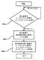
従って、特定の実施形態においては、センサ電子装置アセンブリが身体上に一旦配置され、インビボセンサの少なくとも一部がISF等の体液と接触し、センサが電子装置ユニットに電気的に接続されたら、表示装置の電源をオンにして(または表示装置には継続的に電力が供給されていてもよい)、表示装置のメモリに格納され該メモリからアクセスされるソフトウェアアルゴリズムを実行し、1以上の要求コマンド、制御信号またはデータパケットを生成して身体装着用電子装置に送ることにより、センサによって得られた検体情報が、オン・デマンドで身体装着用電子装置から表示装置に通信され得る。例えば、表示装置のマイクロプロセッサまたは特定用途集積回路(ASIC)の制御下で実行されるソフトウェアアルゴリズムは、生成された要求コマンド、制御信号および/またはデータパケットの送信を開始するために、表示装置に対する身体装着用電子装置の位置を検出するルーチンを含み得る。 Thus, in certain embodiments, once the sensor electronics assembly is placed on the body, at least a portion of the in vivo sensor is in contact with bodily fluids such as ISF, and the sensor is electrically connected to the electronics unit, an indication One or more request commands that turn on the device (or the display device may be continuously powered), execute a software algorithm stored in and accessed from the memory of the display device By generating a control signal or data packet and sending it to the body-worn electronic device, the specimen information obtained by the sensor can be communicated from the body-worn electronic device to the display device on demand. For example, a software algorithm executed under the control of the display device's microprocessor or application specific integrated circuit (ASIC) may cause the display device to initiate transmission of generated request commands, control signals and / or data packets. A routine for detecting the position of the body-worn electronic device may be included.
表示装置は、ユーザによる表示装置上の入力機構の作動(表示装置上のボタンの押下、データ通信機能と関連付けられたソフトボタンのトリガ等)に応答して身体装着用電子装置に送られる1以上の要求コマンド、制御信号またはデータパケットを生成して送信するために、1以上のマイクロプロセッサおよび/またはASICによって実行される、メモリに格納されたプログラミングも含み得る。或いはまたはそれに加えて、身体装着用電子装置上または身体装着用電子装置内に、ユーザによって作動されるよう構成され得る入力機構が設けられてもよい。特定の実施形態では、音声コマンドまたは可聴信号を用いて、マイクロプロセッサまたはASICに、メモリに格納されたソフトウェアルーチンを実行して、1以上の要求コマンド、制御信号またはデータパケットを生成して身体装着用装置に送信するよう促してもまたは指示してもよい。音声によって作動される、または音声コマンド若しくは可聴信号に応答する実施形態では、身体装着用電子装置および/または表示装置は、マイク、スピーカ、並びに、音声コマンドおよび/または可聴信号を処理するための身体装着用電子装置および/または表示装置のそれぞれのメモリに格納された処理ルーチンを含む。特定の実施形態では、身体装着用装置および表示装置を互いにに対して所定の距離内に(例えば、ごく接近して)配置することで、要求コマンド、制御信号またはデータパケットを生成および送信するための表示装置のメモリに格納された1以上のソフトウェアルーチンが開始される。 The display device is sent to the body-worn electronic device in response to the operation of the input mechanism on the display device by the user (pressing a button on the display device, triggering a soft button associated with the data communication function, etc.) It may also include programming stored in memory, executed by one or more microprocessors and / or ASICs, to generate and send a request command, control signal or data packet. Alternatively or in addition, an input mechanism may be provided that may be configured to be actuated by a user on or in the body-worn electronic device. In certain embodiments, a voice command or audible signal is used to execute a software routine stored in memory on a microprocessor or ASIC to generate one or more request commands, control signals or data packets to wear on the body. The device may be prompted or directed to transmit. In embodiments activated by voice or responsive to voice commands or audible signals, the body-worn electronic device and / or display device includes a microphone, a speaker, and a body for processing voice commands and / or audible signals. Processing routines stored in respective memories of the mounting electronic device and / or the display device. In certain embodiments, to generate and transmit a request command, control signal or data packet by positioning the body-worn device and the display device within a predetermined distance (eg, in close proximity) relative to each other. One or more software routines stored in the memory of the display device are started.
各オン・デマンドの読み取りにつき、それぞれ異なるタイプ、形態および/または量の情報が送られ得る。この情報は、現在の検体レベル情報(即ち、読み取りの開始時間に時間的に対応するリアルタイムのまたは直近得られた検体レベル情報)、所定の期間にわたる検体の変化率、検体の変化率の速度(変化率の加速)、所与の読み取り以前に得られてアセンブリのメモリに格納された検体情報に対応する歴史的検体情報の1以上を含むが、それらに限定されない。所与の読み取りにつき、リアルタイム情報、歴史的情報、変化率情報、変化率の速度(加速や減速等)情報の一部または全てが表示装置に送られ得る。特定の実施形態では、表示装置に送られる情報のタイプ、形態および/または量は、予めプログラムされていて且つ/または変更不能であってもよく(例えば、製造時にプリセットされる)、或いは、予めプログラムされておらず且つ/または変更不能でなくてもよく、(例えば、システムのスイッチ等を作動することにより)現場で1回以上選択可能および/または変更可能になっていてもよい。従って、特定の実施形態では、各オン・デマンドの読み取りにつき、表示装置は、センサによって得られた現在の(リアルタイムの)検体値(例えば、数値形式)、検体の現在の変化率(例えば、或る方向を指して現在の変化率を示す矢印等の検体変化率インジケータの形態)、および身体装着用電子装置によって取得されて身体装着用電子装置のメモリに格納されたセンサ測定値に基づく検体動向履歴データ(例えば、グラフの線の形態)を出力する。更に、各オン・デマンドの読み取りと関連付けられた皮膚温度またはセンサ温度の読み取り値または測定値が、身体装着用電子装置から表示装置に通信され得る。しかし、温度の読み取り値または測定値は、表示装置に出力または表示されずに、ユーザに対する表示装置上の検体測定出力を補正または補償するために表示装置によって実行されるソフトウェアルーチンと共に用いられてもよい。 Different types, forms and / or quantities of information may be sent for each on-demand reading. This information includes current sample level information (ie, real-time or most recently obtained sample level information corresponding temporally to the start time of the reading), sample change rate over a predetermined period, sample change rate rate ( Rate of change acceleration), including but not limited to one or more of historical specimen information corresponding to the specimen information obtained prior to a given reading and stored in the memory of the assembly. For a given reading, some or all of the real-time information, historical information, rate of change information, rate of change rate (acceleration, deceleration, etc.) information may be sent to the display. In certain embodiments, the type, form and / or amount of information sent to the display device may be pre-programmed and / or immutable (eg, preset at the time of manufacture) or pre- It may not be programmed and / or not changeable, and may be selectable and / or changeable one or more times in the field (eg, by actuating a system switch or the like). Thus, in certain embodiments, for each on-demand reading, the display device may display the current (real-time) analyte value (eg, numeric format) obtained by the sensor, the current rate of change of the analyte (eg, or Specimen change rate indicator such as an arrow indicating the current rate of change indicating the current direction), and a sensor trend based on sensor measurement values obtained by the body-worn electronic device and stored in the memory of the body-worn electronic device History data (for example, the form of graph lines) is output. Further, skin temperature or sensor temperature readings or measurements associated with each on-demand reading may be communicated from the body-worn electronic device to the display device. However, the temperature reading or measurement may not be output or displayed on the display device, but may be used with a software routine executed by the display device to correct or compensate for the analyte measurement output on the display device to the user. Good.
上述のように、複数の実施形態は、インビボ検体センサおよび身体装着用電子装置を含み、それらは共に、身体に着用可能なセンサ電子装置アセンブリを提供する。特定の実施形態では、インビボ検体センサは身体装着用電子装置と完全に一体化される(製造時に固定されて接続される)が、他の実施形態では、それらは別個のものであって、製造後に(例えば、身体へのセンサの挿入前、挿入中、または挿入後に)接続可能である。身体装着用電子装置は、インビボグルコースセンサ、電子装置、電池およびアンテナを含んでもよく、それらは(生体内に配置されるセンサ部分を除き)防水筐体内に収容される。この筐体は、粘着パッドを有するか、または粘着パッドに取り付け可能である。特定の実施形態では、筐体は、約1メートルの水中において少なくとも30分間までの浸水に耐える。特定の実施形態では、筐体は、例えば、約30分間より長い時間にわたって、水との連続的な接触に耐え、意図された使用に従って適切に(例えば、筐体が浸水に適したものである場合には、筐体の電子装置が水によって損傷されることなく)機能し続ける。 As described above, embodiments include in-vivo analyte sensors and body-worn electronic devices, which together provide a sensor electronics assembly that can be worn on the body. In certain embodiments, the in vivo analyte sensors are fully integrated with the body-worn electronic device (fixed and connected during manufacture), while in other embodiments they are separate and manufactured It can be connected later (eg, before, during, or after insertion of the sensor into the body). The body-worn electronic device may include an in vivo glucose sensor, an electronic device, a battery, and an antenna, which are housed in a waterproof housing (except for the sensor portion that is placed in the living body). This housing has or can be attached to an adhesive pad. In certain embodiments, the enclosure resists flooding for up to at least 30 minutes in about 1 meter of water. In certain embodiments, the housing, for example, withstands continuous contact with water for a period of time greater than about 30 minutes and is appropriate for the intended use (eg, the housing is suitable for flooding). In some cases, the electronics of the housing will continue to function (without being damaged by water).
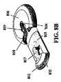
複数の実施形態は、センサ挿入装置(本明細書ではセンサ送出ユニット等とも称する)を含む。挿入装置は、身体装着用電子装置アセンブリを完全に内部区画内に保持し得る。即ち、挿入装置には、製造プロセス中に身体装着用電子装置アセンブリが予め装填され得る(例えば、身体装着用電子装置は、挿入装置の滅菌された内部区画にパックされ得る)。そのような実施形態では、挿入装置は、使用前の、即ち新しい身体装着用電子装置アセンブリのセンサアセンブリパッケージ(滅菌パッケージを含む)を構成してもよく、挿入装置は、身体装着用電子装置アセンブリを受け手の身体に適用するよう構成される。 Embodiments include a sensor insertion device (also referred to herein as a sensor delivery unit or the like). The insertion device can hold the body-worn electronic device assembly completely within the interior compartment. That is, the insertion device can be preloaded with a body-worn electronic device assembly during the manufacturing process (eg, the body-worn electronic device can be packed into a sterilized internal compartment of the insertion device). In such embodiments, the insertion device may constitute a sensor assembly package (including a sterilization package) of the pre-use, ie new body-worn electronic device assembly, including the body-worn electronic device assembly. Configured to apply to the recipient's body.
複数の実施形態は、身体装着用電子装置アセンブリから離間された別個の装置として、手で持って操作できる携帯表示装置を含み、該表示装置は、アセンブリから情報を収集して、センサによって得られた検体測定値をユーザに提供する。そのような装置は、計測器、読み取り器、モニタ、受信器、ヒューマンインターフェイス装置、コンパニオン等とも称され得る。特定の実施形態は、一体化されたインビトロ検体計測器を含み得る。特定の実施形態では、表示装置は、表示装置と別の装置(例えば、身体装着用電子装置、電池を充電するための電源装置、PC等)との通信を確立するよう構成された1以上の有線または無線通信ポート(USBポート、シリアルポート、パラレルポート等)を含む。例えば、表示装置の通信ポートは、個別の充電用ケーブルを用いて表示装置の電池の充電を可能にしてもよく、且つ/または、表示装置とそれに適合するインフォマティクスソフトウェアとのデータ交換を可能にしてもよい。 Embodiments include a portable display device that can be held and operated by hand as a separate device spaced from the body-worn electronic device assembly, wherein the display device collects information from the assembly and is obtained by a sensor. Provide the sample measurement value to the user. Such a device may also be referred to as a meter, reader, monitor, receiver, human interface device, companion, etc. Certain embodiments may include an integrated in vitro analyte meter. In certain embodiments, the display device is configured to establish communication between the display device and another device (eg, a body-worn electronic device, a power supply for charging a battery, a PC, etc.). Includes wired or wireless communication ports (USB port, serial port, parallel port, etc.). For example, the communication port of the display device may allow the battery of the display device to be charged using a separate charging cable and / or allows data exchange between the display device and the corresponding informatics software. Also good.
特定の実施形態における適合するインフォマティクスソフトウェアは、例えば、データ解析、カルテ記入、データ格納、データ保管およびデータ通信、並びにデータ同期化を行うための、例えば、表示装置、パーソナルコンピュータ、サーバ端末に常駐しているかまたはそこで実行される、スタンドアロン型のまたはネットワーク接続によって使用可能なデータ管理ソフトウェアプログラムを含むが、それに限定されない。特定の実施形態におけるインフォマティクスソフトウェアは、例えば、追加の特徴および/またはソフトウェアのバグやエラーの修正等を含むファームウェアのバージョンを用いて表示装置および/または身体装着用電子装置ユニットの常駐ソフトウェアをアップグレードするために、表示装置および/または身体装着用電子装置ユニットのファームウェアをアップグレードするためのフィールドアップグレード可能な機能を実行するソフトウェアも含み得る。 Suitable informatics software in certain embodiments resides in, for example, display devices, personal computers, server terminals, for example, for data analysis, chart entry, data storage, data storage and data communication, and data synchronization. Including, but not limited to, data management software programs that can be used or run on a stand-alone or network connection. The informatics software in certain embodiments upgrades the resident software of the display device and / or the body-worn electronic device unit with, for example, a firmware version that includes additional features and / or correction of software bugs and errors, etc. To that end, it may also include software that performs field upgradable functions for upgrading the firmware of the display device and / or the body-worn electronic device unit.
複数の実施形態は、対応する通知(例えば、表示装置における良好なオン・デマンドの測定値の受信)が触覚的フィードバックの形態で届けられるよう構成された、触覚的フィードバックの特徴(振動モータ等)を含み得る。 Embodiments include tactile feedback features (vibration motors, etc.) configured such that corresponding notifications (eg, receipt of good on-demand measurements at a display device) are delivered in the form of tactile feedback. Can be included.
複数の実施形態は、システムから得られた検体情報および/またはユーザが自分で報告したデータを処理するための、コンピュータ可読媒体に埋め込まれたプログラミング、即ち、コンピュータベースのアプリケーションソフトウェア(本明細書では、インフォマティクスソフトウェアまたはプログラミング等とも称される)を含む。アプリケーションソフトウェアは、表示装置または身体装着用電子装置ユニットによって、携帯電話、PC、インターネットに接続可能なヒューマンインターフェイス装置(インターネットに接続可能な電話、パーソナルデジタルアシステント等)等のホストコンピュータにインストールされ得る。インフォマティクスプログラミングは、取得されて表示装置または身体装着用ユニットに格納されたデータを、ユーザによる使用のために変換し得る。 Embodiments include programming embedded in a computer readable medium, ie, computer-based application software (herein, for processing sample information obtained from the system and / or data reported by the user himself / herself. , Also called informatics software or programming). Application software can be installed on a host computer such as a mobile phone, a PC, or a human interface device that can be connected to the Internet (such as a phone that can be connected to the Internet, a personal digital assistant, etc.) by a display device or a body-worn electronic device unit. . Informatics programming can transform the data acquired and stored in a display device or body-worn unit for use by a user.
主題の開示の複数の実施形態は、便宜的に、主に、グルコースモニタリング装置およびシステム、並びにグルコースモニタリング方法に関して説明されるが、そのような説明は、決して本開示の範囲を限定することを意図するものではない。検体モニタリングシステムは、様々な検体を同時にまたは異なるタイミングでモニタリングするよう構成され得ることを理解されたい。 While embodiments of the subject disclosure are described primarily with respect to glucose monitoring devices and systems, and glucose monitoring methods for convenience, such descriptions are in no way intended to limit the scope of the present disclosure. Not what you want. It should be understood that the analyte monitoring system can be configured to monitor various analytes simultaneously or at different times.
例えば、モニタリングされ得る検体としては、アセチルコリン、アミラーゼ、ビリルビン、コレステロール、絨毛性ゴナドトロピン、クレアチンキナーゼ(例えば、CK−MB)、クレアチン、DNA、フルクトサミン、グルコース、グルタミン、成長ホルモン、ホルモン、ケトン、乳酸、酸素、過酸化物、前立腺特異抗原、プロトロンビン、RNA、甲状腺刺激ホルモンおよびトロポニンが挙げられるが、これらに限定されない。例えば、抗生物質(例えば、ゲンタマイシン、バンコマイシン等)、ジギトキシン、ジゴキシン、乱用薬物、テオフィリンおよびワルファリン等の薬剤の濃度もモニタリングされ得る。2以上の検体をモニタリングするこれらの実施形態では、それらの検体は、単一のセンサを用いて、または同じ身体装着用電子装置を(例えば同時に)用い得る若しくは異なる身体装着用電子装置を用い得る複数のセンサを用いて、同時にまたは異なるタイミングでモニタリングされ得る。 For example, acetylcholine, amylase, bilirubin, cholesterol, chorionic gonadotropin, creatine kinase (eg, CK-MB), creatine, DNA, fructosamine, glucose, glutamine, growth hormone, hormone, ketone, lactic acid, Examples include, but are not limited to oxygen, peroxide, prostate specific antigen, prothrombin, RNA, thyroid stimulating hormone and troponin. For example, the concentration of drugs such as antibiotics (eg, gentamicin, vancomycin, etc.), digitoxin, digoxin, drugs of abuse, theophylline and warfarin can also be monitored. In these embodiments for monitoring two or more analytes, the analytes may use a single sensor or may use the same body-worn electronic device (eg, simultaneously) or different body-worn electronic devices. Multiple sensors can be used to monitor simultaneously or at different times.
以下に詳細に説明するように、複数の実施形態は、例えば、所定のモニタリング期間にわたる検体レベル、温度レベル、心拍数、ユーザの活動レベル等であるが、それらに限定されない、1以上の生理学的パラメータをモニタリングするための装置、システム、キットおよび/または方法を含む。製造方法も提供される。所定のモニタリング期間は、約1時間未満であってもよく、または、約1時間以上(例えば約数時間以上、例えば約数日間以上、例えば約3日間以上、例えば約5日間以上、例えば約7日間以上、例えば約10日間以上、例えば約14日間以上、例えば約数週間、例えば約1ヶ月以上)であってもよい。特定の実施形態では、所定のモニタリング期間の終了後、身体装着用電子装置アセンブリおよび/または表示装置において、システムの1以上の特徴が自動的に非アクティブ化または無効にされ得る。 As described in detail below, embodiments may include, for example, but not limited to, one or more physiological levels such as, but not limited to, analyte level, temperature level, heart rate, user activity level, etc. over a predetermined monitoring period. Includes devices, systems, kits and / or methods for monitoring parameters. A manufacturing method is also provided. The predetermined monitoring period may be less than about 1 hour, or about 1 hour or more (eg, about several hours or more, eg, about several days or more, eg, about 3 days or more, eg, about 5 days or more, eg, about 7 Days or more, for example about 10 days or more, for example about 14 days or more, for example about several weeks, for example about 1 month or more). In certain embodiments, one or more features of the system may be automatically deactivated or disabled in the body-worn electronic device assembly and / or display device after the end of a predetermined monitoring period.
例えば、所定のモニタリング期間は、センサを生体内に配置してISF等の体液と接触させることによって、且つ/または、身体装着用電子装置の開始によって(または電源を入れて完全動作モードにすることによって)開始し得る。身体装着用電子装置の初期化は、スイッチの作動に応答して、且つ/または表示装置を身体装着用電子装置から所定の距離内に(例えば、ごく接近して)配置することによって、或いは、ユーザが手動で身体装着用電子装置ユニットのスイッチを作動させる(例えばボタンを押下する)ことによって、表示装置によって生成され送信されるコマンドによって実施され得る。或いは、そのような作動は、例えば、2010年2月1日に出願された米国特許出願第12/698,129号明細書、並びに米国特許仮出願第61/238,646号、同第61/246,825号、同第61/247,516号、同第61/249,535号、同第61/317,243号、同第61/345,562号および同第61/361,374号の各明細書(それぞれの開示をあらゆる目的で参照して本明細書に組み込む)に記載されているように、挿入装置が生じさせてもよい。 For example, during a predetermined monitoring period, the sensor is placed in the living body and brought into contact with a bodily fluid such as ISF, and / or by the start of a body-worn electronic device (or power on to enter full operation mode) Can start). Initialization of the body-worn electronic device may be in response to actuation of the switch and / or by placing the display device within a predetermined distance (eg, in close proximity) from the body-worn electronic device, or It may be implemented by a command generated and transmitted by the display device by a user manually actuating a switch on the body-worn electronic device unit (eg, pressing a button). Alternatively, such operations are described, for example, in US patent application Ser. No. 12 / 698,129 filed Feb. 1, 2010, and US provisional application Nos. 61 / 238,646, 61/61. 246,825, 61 / 247,516, 61 / 249,535, 61 / 317,243, 61 / 345,562 and 61 / 361,374. An insertion device may be created as described in each specification (the respective disclosures are incorporated herein by reference for all purposes).
身体装着用電子装置は、表示装置から受信したコマンドに応答して初期化されると、そのメモリからソフトウェアルーチンを取り出して実行して、身体装着用電子装置の構成要素の電源を完全にオンにすることにより、表示装置からの作動コマンドの受信に応答して身体装着用電子装置を完全動作モードにする。例えば、表示装置からコマンドを受信する前に、身体装着用電子装置の内部電源(電池等)によって身体装着用電子装置の構成要素の一部に電力が供給されてもよく、一方、身体装着用電子装置の構成要素の別の一部は電源オフ状態または低電力状態(電力供給が無い非アクティブモードを含む)であってもよく、または、全ての構成要素が非アクティブモード、電源オフモードであってもよい。コマンドを受信したら、身体装着用電子装置の構成要素の残りの部分(または全て)がアクティブな完全動作モードに切り替えられる。 When the body-worn electronic device is initialized in response to a command received from the display device, it retrieves and executes a software routine from its memory to fully power on the body-worn electronic device components. By doing so, the body-worn electronic device is put into the full operation mode in response to receiving the operation command from the display device. For example, before receiving a command from the display device, power may be supplied to some of the components of the body-worn electronic device by the internal power supply (battery etc.) of the body-worn electronic device, Another part of the components of the electronic device may be in a power off state or low power state (including inactive mode with no power supply) or all components in inactive mode, power off mode There may be. Upon receipt of the command, the remaining (or all) components of the body-worn electronic device are switched to the active full mode of operation.
身体装着用電子装置の複数の実施形態は、ASIC、マイクロプロセッサ、メモリ等に実装された制御論理を含む電子装置を有する1以上のプリント基板と、経皮的に配置可能な検体センサとを含んで、単一のアセンブリを構成し得る。身体装着用電子装置は、或る期間(例えば約2分間、例えば1分間以下、例えば約30秒間以下、例えば約10秒間以下、例えば約5秒間以下、例えば約2秒間以下)にわたって所定の近傍内に検体モニタリングシステムの表示装置が検出された際に、且つ/または、身体装着用電子装置からの検体関連信号の良好な取得を示す確認(可聴通知、視覚的通知および/または触覚的通知(例えば振動)等)が表示装置に出力されるまで、モニタリングされた検体レベルと関連付けられた1以上の信号またはデータパケットを供給するよう構成され得る。特定の実施形態では、取得の失敗についても、区別可能な通知が出力され得る。 Embodiments of a body-worn electronic device include one or more printed circuit boards having an electronic device that includes control logic implemented in an ASIC, microprocessor, memory, etc., and a percutaneously displaceable analyte sensor. Thus, a single assembly can be constructed. The body-worn electronic device is within a predetermined proximity over a period of time (eg about 2 minutes, eg 1 minute or less, eg about 30 seconds or less, eg about 10 seconds or less, eg about 5 seconds or less, eg about 2 seconds or less). Confirmation (eg, audible notification, visual notification and / or tactile notification (e.g., audible notification, visual notification and / or tactile notification) when a display device of the sample monitoring system is detected and / or a good acquisition of the sample related signal from the body-worn electronic device is detected. Vibrations, etc.) may be configured to provide one or more signals or data packets associated with the monitored analyte level until output to the display device. In certain embodiments, distinct notifications may also be output for acquisition failures.
特定の実施形態では、モニタリングされた検体レベルは、血中または他の流体中(ISF等)のグルコースレベルに相関および/または変換され得る。そのような変換は、身体装着用電子装置を用いて達成されてもよいが、多くの実施形態では、表示装置の電子装置を用いて達成される。特定の実施形態では、グルコースレベルは、モニタリングされたISF中の検体レベルから得られる。 In certain embodiments, monitored analyte levels can be correlated and / or converted to glucose levels in blood or other fluids (such as ISF). Such a conversion may be accomplished using a body-worn electronic device, but in many embodiments is accomplished using a display device electronic device. In certain embodiments, the glucose level is obtained from the analyte level in the monitored ISF.
検体センサは、静脈、動脈、または身体の検体を含む他の部分に挿入可能であり得る。特定の実施形態では、検体センサは、検体のレベルを検出するためにISFと接触するよう配置され得る。この場合、検出された検体レベルは、ユーザの血中または間質組織中のグルコースレベルを推測するために用いられ得る。 The analyte sensor may be insertable into veins, arteries, or other parts that contain bodily analytes. In certain embodiments, the analyte sensor can be placed in contact with the ISF to detect the level of the analyte. In this case, the detected analyte level can be used to infer the glucose level in the user's blood or interstitial tissue.
複数の実施形態は、経皮的センサと、完全に埋め込み可能なセンサと、完全に埋め込み可能なアセンブリとを含み、この場合、検体センサおよび電子装置を含む単一のアセンブリが密閉された筐体(例えば、密閉された生体適合筐体)内に設けられて、1以上の生理学的パラメータをモニタリングするためにユーザの身体に埋め込まれる。 Embodiments include a transcutaneous sensor, a fully implantable sensor, and a fully implantable assembly, where a single assembly containing an analyte sensor and an electronic device is sealed (E.g., a sealed biocompatible housing) and is implanted in the user's body for monitoring one or more physiological parameters.
(インビボ検体モニタリングシステムの実施形態)
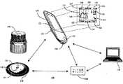
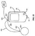
図1は、本開示の複数の実施形態による例示的なインビボベースの検体モニタリングシステム100を示す。図示されるように、特定の実施形態では、検体モニタリングシステム100は身体装着用電子装置110を含み、身体装着用電子装置110は、インビボ検体センサ101(図1にはその近位部が示されている)に電気的に接続されると共に、ユーザの身体の皮膚表面への取り付けのために接着層140に取り付けられている。身体装着用電子装置110は、内部区画を画成する身体装着用筐体119を含む。図1には挿入装置150も示されており、挿入装置150は、操作された際に、検体センサ101を経皮的に皮膚表面を通して配置してISFと流体接触させると共に、身体装着用電子装置110および接着層140を皮膚表面に配置する。特定の実施形態では、身体装着用電子装置110、検体センサ101および接着層140は、使用前には挿入装置150の筐体内に密封されており、特定の実施形態では、接着層140も筐体内に密封されているか、または接着層140自体が挿入装置150の末端シールとなっている。本明細書の複数の実施形態と共に用いられ得る装置、システムおよび方法は、例えば、米国特許出願第12/698,129号明細書、並びに米国特許仮出願第61/238,646号、同第61/246,825号、同第61/247,516号、同第61/249,535号、同第61/317,243号、同第61/345,562号および同第61/361,374号の各明細書に記載されており、それぞれの開示をあらゆる目的で参照して本明細書に組み込む。(Embodiment of in vivo specimen monitoring system)
FIG. 1 illustrates an exemplary in vivo-based
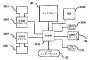
図1に戻ると、検体モニタリングシステム100は表示装置120を含み、表示装置120は、ユーザに情報を出力するためのディスプレイ122と、表示装置120にデータやコマンドを入力するための、または別様で表示装置120の動作を制御するための入力要素121(例えば、ボタン、アクチュエータ、タッチセンサ式スイッチ、容量性スイッチ、感圧スイッチ、ジョグホイール等)とを含む。なお、幾つかの実施形態は、ディスプレイの無い装置、または、いかなるユーザインターフェイス要素も無い装置を含み得る。これらの装置には、データロガーとしてデータを格納し、且つ/または、身体装着用電子装置および/またはディスプレイの無い装置から、別の装置および/または場所にデータを転送するための導管を提供する機能が設けられ得る。本明細書には、例示の目的で、表示装置としての複数の実施形態を説明するが、それらが本開示の実施形態を限定することは決して意図されない。特定の実施形態においてはディスプレイの無い装置も用いられ得ることは自明である。 Returning to FIG. 1, the
特定の実施形態では、身体装着用電子装置110は、モニタリング期間中に検体センサ101から受信した、モニタリングされた検体に関連するデータの一部または全てをメモリに格納し、使用期間が終わるまでメモリ内に維持するよう構成され得る。そのような実施形態では、格納されデータは、モニタリング期間の最後(例えば、身体装着用電子装置110を、それがモニタリング期間中に配置された皮膚表面から取り外すことによって、検体センサ101をユーザから除去した後)に、身体装着用電子装置110から取り出される。そのようなデータ記録構成においては、リアルタイムでモニタリングされた検体レベルは、モニタリング期間中に表示装置120に通信または別様で身体装着用電子装置110から送信されることはなく、モニタリング期間の後に身体装着用電子装置110から取り出される。 In certain embodiments, the body-worn
特定の実施形態では、表示装置の120の機能および動作が音声コマンドによって制御され得るように、表示装置120の入力要素121はマイクを含んでもよく、表示装置120は、マイクから受信した音声入力を解析するよう構成されたソフトウェアを含んでもよい。特定の実施形態では、表示装置120の出力要素は、情報を可聴信号として出力するためのスピーカを含む。身体装着用電子装置110にも、スピーカ、マイク、および音声によって駆動される信号を生成、処理および格納するためのソフトウェアルーチン等の、音声に応答する類似の構成要素が設けられてもよい。 In certain embodiments, the
特定の実施形態では、ディスプレイ122および入力要素121は単一の構成要素(例えば、タッチスクリーン式ユーザインターフェイス等といった、ディスプレイ上での物理的な接触の存在および位置を検出できるディスプレイ)として一体化され得る。そのような実施形態では、ユーザは、ディスプレイを1回または2回叩くこと、ディスプレイ上で指または道具をドラッグすること、複数の指または道具を互いに向かって動かすこと、複数の指または道具を互いから離れるように動かすこと等を含むが、それらに限定されない、予めプログラムされた一組のモーションコマンドを用いて、表示装置120の動作を制御してもよい。特定の実施形態では、ディスプレイは、LCD素子およびタッチセンサとして作用する単機能または二重機能の容量性素子を備えた画素領域を有するタッチスクリーンを含む。 In certain embodiments,
また、表示装置120は、例えば遠隔端末(パーソナルコンピュータ)170等の外部装置との有線データ通信のためのデータ通信ポート123を含む。データ通信ポート123の例示的な実施形態は、USBポート、ミニUSBポート、RS−232ポート、Ethernet(登録商標)ポート、Firewire(登録商標)ポート、または適合するデータケーブルと接続するよう構成された他の類似のデータ通信ポートを含む。表示装置120は、インビトロ血中グルコース測定を行うためにインビトログルコース試験紙を受け付けるインビトロ試験紙ポート124を有する一体化されインビトログルコース計も含み得る。 The
引き続き図1を参照すると、特定の実施形態におけるディスプレイ122は、様々な情報を表示するよう構成され、その一部または全ては、ディスプレイ122上に同時にまたは異なるタイミングで表示され得る。特定の実施形態では、所与の表示画面に示される情報をユーザがカスタマイズできるように、表示される情報はユーザが選択可能である。ディスプレイ122は、例えば、モニタリングされた期間にわたるグルコース値のグラフ出力を提供するグラフ表示138(食事、運動、睡眠、心拍数、血圧等の重要なマーカーも示し得る)、例えば、モニタリングされたグルコース値(情報に対する要求に応答して取得または受信される)を提供する数値表示132、および、例えば、ディスプレイ122上で位置を移動することにより検体の変化率および/または検体の変化率の速度を示す動向または方向の矢印表示131を含み得るが、それらに限定されない。 With continued reference to FIG. 1, the
図1に更に示されるように、ディスプレイ122は、例えば、ユーザに日付情報を提供する日付表示135、ユーザに時刻情報を提供する時刻情報表示139、表示装置120の電池(再充電可能または使い捨て)の状態をグラフで示す電池レベルインジケータ表示133、例えば、周期的、定期的または所定数のユーザ較正事象が必要なモニタリングシステムにおいて、検体センサの較正が必要であることをユーザに通知するセンサ較正状態アイコン表示134、音声/振動出力または警報の状態を表示する音声/振動設定アイコン表示136、並びに、他の装置(身体装着用電子装置、データ処理モジュール160、および/または遠隔端末170等)との無線通信接続の表示を提供する無線接続性状態アイコン表示137も含み得る。図1に更に示されるように、ディスプレイ122は、メニューにアクセスするため、表示グラフ出力設定を変更するため、または別様で表示装置120の動作を制御するための擬似タッチスクリーンボタン125、126を更に含み得る。 As further shown in FIG. 1, the
図1に戻ると、特定の実施形態では、表示装置120のディスプレイ122は、視覚的表示に加えてまたは視覚的表示の代わりに、警報通知(例えばグルコース値等の警報および/または警告通知等)を出力するよう構成され得る。警報通知は、可聴通知、触覚的通知、またはそれらの任意の組み合わせであり得る。1つの態様において、表示装置120は、ディスプレイ122上で提供される視覚的出力表示に加えて、ユーザに可聴出力表示および/または振動出力表示を提供するためのスピーカや振動出力要素等の他の出力要素を含み得る。更なる詳細及び他の表示の実施形態は、例えば、米国特許出願第12/871,901号明細書、並びに、米国特許仮出願第61/238,672号、同第61/247,541号および同第61/297,625号の各明細書に見出すことができ、それぞれの開示をあらゆる目的で参照して本明細書に組み込む。 Returning to FIG. 1, in certain embodiments, the
身体装着用電子装置110が皮膚表面に配置され、且つ検体センサ101が生体内に配置されてISF(または他の適切な体液)との流体接触が確立された後、特定の実施形態における身体装着用電子装置110は、身体装着用電子装置110が表示装置120からのコマンドまたは要求信号を受信した際、検体関連データ(例えば、モニタリングされた検体レベルに対応するデータ、モニタリングされた温度データ、および/または格納されている歴史的検体関連データ等)を無線で通信するよう構成される。特定の実施形態では、身体装着用電子装置110は、表示装置120が身体装着用電子装置110からのデータブロードキャストの通信距離内にあるときに、表示装置120によって受信されたモニタリングされた検体レベルと関連付けられたリアルタイムのデータを、少なくとも周期的にブロードキャストするよう構成され得る(即ち、情報を送信するために表示装置からのコマンドまたは要求を必要としない)。 Body wear in certain embodiments after body wear
例えば、表示装置120は、身体装着用電子装置110にデータ転送を開始するための1以上のコマンドを送信するよう構成され得る。それに応答して、身体装着用電子装置110は、モニタリング期間中に収集された格納されている検体関連データを、表示装置120に無線で送信するよう構成され得る。表示装置120は、更に、パーソナルコンピュータ等の遠隔端末170に接続されてもよく、格納されている検体レベル情報を身体装着用電子装置110から遠隔端末170に転送するためのデータの導管として機能する。特定の実施形態では、身体装着用電子装置110から受信されたデータは、表示装置120の1以上のメモリに(永久的にまたは一時的に)格納され得る。他の特定の実施形態では、表示装置120は、身体装着用電子装置110から受信したデータを表示装置120に接続された遠隔端末170に渡すためのデータの導管として構成される。 For example,
引き続き図1を参照すると、検体モニタリングシステム100には、データ処理モジュール160および遠隔端末170も示されている。遠隔端末170は、データの管理および解析、並びに検体モニタリングシステム100の構成要素との通信のためのソフトウェアを含むパーソナルコンピュータ、サーバ端末、ラップトップコンピュータ、または他の適切なデータ処理装置を含み得る。例えば、遠隔端末170は、遠隔端末170と表示装置120および/またはデータ処理モジュール160との単方向または双方向データ通信のために、ローカルエリアネットワーク(LAN)、ワイドエリアネットワーク(WAN)、または他のデータネットワークに接続され得る。 With continued reference to FIG. 1, the
特定の実施形態における遠隔端末170は、外科医のオフィスや病院に配置された1以上のコンピュータ端末を含み得る。例えば、遠隔端末170は、表示装置120の場所以外の場所に配置され得る。遠隔端末170および表示装置120は、それぞれ異なる部屋または異なる建物にあってもよい。遠隔端末170および表示装置120は、少なくとも約1マイル(約1.6キロメートル)離れていてもよい(例えば少なくとも約10マイル(約16キロメートル)離れていてもよく、例えば少なくとも約100マイル(約160キロメートル)離れていてもよい)。例えば、遠隔端末170は表示装置120と同じ市内にあってもよく、遠隔端末170は表示装置120と異なる市にあってもよく、遠隔端末170は表示装置120と同じ州内にあってもよく、遠隔端末170は表示装置120と異なる州にあってもよく、遠隔端末170は表示装置120と同じ国内にあってもよく、遠隔端末170は表示装置120と異なる国にあってもよい。 The
特定の実施形態では、検体モニタリングシステム100には、データ処理モジュール160等の別個の必要に応じて設けられるデータ通信/処理装置が設けられ得る。データ処理モジュール160は、例えば、赤外線(IR)プロトコル、Bluetooth(登録商標)プロトコル、Zigbee(登録商標)プロトコルおよび802.11無線LANプロトコル等であるが、それらに限定されない1以上の無線通信プロトコルを用いて通信するための構成要素を含み得る。Bluetooth(登録商標)プロトコルおよび/またはZigbee(登録商標)プロトコルに基づくものを含む通信プロトコルの更なる説明は、米国特許出願公開第2006/0193375号明細書に見出すことができ、その内容をあらゆる目的で参照して本明細書に組み込む。データ処理モジュール160は、1以上の表示装置120、身体装着用電子装置110、または遠隔端末170との有線通信を確立するための、例えば、USBコネクタおよび/またはUSBポート、Ethernet(登録商標)コネクタおよび/またはポート、FireWireコネクタおよび/またはポート、またはRS−232ポートおよび/またはコネクタを含むがそれらに限定されない通信ポート、ドライバまたはコネクタを更に含み得る。 In certain embodiments, the
特定の実施形態では、データ処理モジュール160は、身体装着用電子装置110に所定の時間間隔(例えば、1分毎に1回、5分毎に1回等)でポーリングまたはクエリー信号を送信すると共に、それに応答して、身体装着用電子装置110からモニタリングされた検体レベル情報を受信するようプログラムされる。データ処理モジュール160は、そのメモリに受信した検体レベル情報を格納し、且つ/または、受信した情報を、表示装置120等の別の装置に中継または再送信する。より具体的には、特定の実施形態において、データ処理モジュール160は、身体装着用電子装置110から受信した検体レベルデータを、表示装置120若しくは遠隔端末(例えば、携帯電話ネットワークまたはWiFiデータネットワーク等のデータネットワークを介して)またはそれらの両方に再送信するまたは渡すためのデータ中継装置として構成され得る。 In certain embodiments, the
特定の実施形態では、身体装着用電子装置110およびデータ処理モジュール160は、身体装着用電子装置110とデータ処理モジュール160との間の周期的な通信が維持されるように、互いから所定の距離(例えば、約1〜12インチ、約1〜10インチ、約1〜7インチ、または約1〜5インチ(1インチは約2.54センチメートル))以内のユーザの皮膚表面に配置され得る。或いは、身体装着用電子装置110とデータ処理モジュール160との間の通信のための所望の距離が維持されるように、データ処理モジュール160はユーザのベルトや衣服に装着されてもよい。更なる態様では、身体装着用電子装置110およびデータ処理モジュール160が単一のアセンブリとして組み合わされまたは一体化されて、皮膚表面に配置されるように、データ処理モジュール160の筐体は、身体装着用電子装置110と接続または係合するよう構成され得る。更なる実施形態では、データ処理モジュール160は、身体装着用電子装置110に取り外し可能に係合または接続され、これにより、データ処理モジュール160が所望により必要に応じて取り外されまたは再取り付けされ得るようなモジュール性を更に提供する。 In certain embodiments, the body-worn
再び図1を参照すると、特定の実施形態において、データ処理モジュール160は、所定の時間間隔(例えば毎分1回、5分毎に1回、30分毎に1回、または他の任意の適切な若しくは所望のプログラム可能な時間間隔等)で、身体装着用電子装置110に、身体装着用電子装置110からの検体関連データを要求するためのコマンドまたは信号を送信するようプログラムされる。データ処理モジュール160が要求した検体関連データを受信すると、データ処理モジュール160は受信したデータを格納する。このように、検体モニタリングシステム100は、連続的にモニタリングされた検体関連情報を、プログラムされたまたはプログラム可能な時間間隔で受信するよう構成され得る。受信された検体関連情報は格納され且つ/またはユーザに対して表示される。データ処理モジュール160に格納されたデータは、次に、治療に関する決定を改善するための次のデータ解析(例えば、モニタリング期間にわたる血糖レベルの偏位期間の頻度やモニタリング期間中に警報事象が生じた頻度の識別等)のために、表示装置120や遠隔端末170等に供給または送信され得る。この情報を用いて、医師、ヘルスケア提供者またはユーザは、食事、生活習慣および運動等の日課を調節し、またはそれらを修正することを推奨し得る。 Referring again to FIG. 1, in certain embodiments, the
別の実施形態では、データ処理モジュール160は、身体装着用電子装置110に、データ処理モジュール160に設けられたスイッチのユーザによる作動または表示装置120から受信したユーザ起動コマンドに応答して、検体関連データを受信するためのコマンドまたは信号を送信する。更なる実施形態では、データ処理モジュール160は、所定の時間間隔の経過後にのみ、ユーザ起動コマンドの受信に応答して、身体装着用電子装置110にコマンドまたは信号を送信するよう構成される。例えば、特定の実施形態では、ユーザが、プログラムされた期間内(例えば前回の通信から約5時間、前回の通信から10時間、または前回の通信から24時間等)に通信を開始しない場合には、データ処理モジュール160は、身体装着用電子装置110に要求コマンドまたは信号を自動的に送信するようプログラムされ得る。或いは、データ処理モジュール160は、データ処理モジュール160と身体装着用電子装置110との間の前回の通信から所定の期間が経過したことをユーザに通知する警報を作動させるようプログラムされ得る。このように、ユーザまたはヘルスケア提供者は、ユーザが頻繁な検体レベル判定を維持し得るまたは行い得るように、データ処理モジュール160を、検体モニタリングのレジメンとの一定の整合性を提供するようプログラムまたは設定し得る。 In another embodiment, the
特定の実施形態では、プログラムされたまたはプログラム可能な警報条件が検出された場合(例えば、検体センサ101によってモニタリングされた、検出されたグルコースレベルが、所定の許容可能範囲外にあり、医療処置または解析のための注意または介入を要する生理学的条件(例えば、低血糖条件、高血糖条件、切迫性高血糖条件または切迫性低血糖条件)を示す場合)には、適時に是正措置がとられ得るように、身体装着用電子装置110の制御論理またはプロセッサによって1以上の出力表示が生成されて、身体装着用電子装置の110ユーザインターフェイス上でユーザに対して出力され得る。それに加えてまたはその代わりに、表示装置120が通信距離内にある場合には、出力表示または警報データは表示装置120に通信されてもよく、警報データの受信が検出されると、表示装置120のプロセッサがディスプレイ122を制御して1以上の通知を出力する。 In certain embodiments, if a programmed or programmable alarm condition is detected (eg, the detected glucose level monitored by the
特定の実施形態では、身体装着用電子装置110の制御論理またはマイクロプロセッサは、検体センサ101から得られた情報(例えば、現在の検体レベル、検体レベルの変化率、検体レベルの変化の加速、および/または、格納されているモニタリングされた検体データに基づいて決定され、モニタリングされた期間中の時間の関数としての検体レベルの変動の歴史的動向または方向を提供する検体動向情報)に基づいて、将来のまたは予期される検体レベルを決定するためのソフトウェアプログラムを含む。予報警報パラメータは、表示装置120、身体装着用電子装置110、またはそれらの両方においてプログラムされ得るかまたはプログラム可能であり、ユーザの検体レベルがその将来のレベルに達することが予想される前に、ユーザに対して出力され得る。これにより、適時な是正措置をとる機会がユーザに与えられる。 In certain embodiments, the control logic or microprocessor of the body-worn
このような検体動向情報を与える、モニタリング期間にわたる時間の関数としてのモニタリングされた検体レベルの変化または変動等の情報は、例えば、表示装置120、データ処理モジュール160、遠隔端末170および/または身体装着用電子装置110の1以上の制御論理またはマイクロプロセッサによって決定され得る。そのような情報は、例えば、検体モニタリングシステム100によって測定および予測された、現在の検体レベル、歴史的検体レベル、および/または予測される将来の検体レベルをユーザに対して示すグラフ(線グラフ等)として表示され得る。そのような情報は、方向を示す矢印(例えば、動向または方向を示す矢印表示131を参照)または他のアイコン(例えば、画面上の基準点に対するそのアイコンの位置が、検体レベルの増減、並びに、検体レベルの増減の加速または減速を示す)としても表示され得る。この情報は、ユーザによって、検体レベルが許容可能範囲内および/または臨床的に安全な範囲内に留まることを確実にするために必要な何らかの是正措置を決定するために用いられ得る。他の視覚的インジケータ(例えば、色、フラッシュ、フェード等)、並びに、音声インジケータ(例えば、音声出力のピッチ、ボリューム若しくはトーンの変化等)および/または振動等の触覚インジケータも、モニタリングされた検体レベルの現在のレベル、方向、および/または変化率をユーザに通知する手段として、動向データの表示に組み込まれ得る。例えば、決定されたグルコースの変化率、プログラムされた臨床的に有意なグルコース閾値レベル(例えば、高血糖レベルおよび/または低血糖レベル)、およびインビボ検体センサによって得られた現在の検体レベルに基づき、システム100は、臨床的に有意なレベルに達するまでにかかる時間を決定するためのコンピュータ可読媒体に格納されたアルゴリズムを含んでもよく、臨床的に有意なレベルに達する前に(例えば、臨床的に有意なレベルになることが予期される30分前、20分前、10分前、5分前、3分前、および/または1分前等)、通知を出力する(例えば出力の強度等を高めながら)。 Information such as changes or fluctuations in the monitored analyte level as a function of time over the monitoring period that provides such analyte trend information may be, for example,
再び図1に戻ると、特定の実施形態では、データ処理モジュール160によって実行されるソフトウェアアルゴリズムは、外部メモリ装置(例えば、SDカード、マイクロSDカード、コンパクトフラッシュ(登録商標)カード、XDカード、メモリースティックカード、メモリースティックDuoカード、またはUSBメモリースティック/デバイス等)に格納され得る。そのような外部メモリ装置には、身体装着用電子装置110、遠隔端末170または表示装置120の1以上にそれぞれ接続された際に実行される、実行可能なプログラムが格納される。更なる態様では、データ処理モジュール160によって実行されるソフトウェアアルゴリズムは、携帯電話等の通信装置(例えば、WiFiまたはインターネットを使用可能なスマートフォンやパーソナルデジタルアシステント(PDA)を含む)に、ダウンロードした通信装置によって実行されるダウンロード可能なアプリケーションとして供給され得る。 Returning again to FIG. 1, in certain embodiments, the software algorithms executed by the
スマートフォンの例としては、インターネット接続および/またはローカルエリアネットワーク(LAN)を介したデータ通信のためのデータネットワーク接続機能を有する、Windows(登録商標)、Android(商標)、iPhone(登録商標)オペレーティングシステム、Palm(登録商標)WebOS(商標)、Blackberry(登録商標)オペレーティンシステム、またはSymbian(登録商標)オペレーティンシステムに基づく携帯電話が挙げられる。上述のPDAとしては、例えば、1以上のマイクロプロセッサおよびデータ通信機能を有し、ユーザインターフェイス(例えば、ディスプレイ/出力部、および/または入力部)を有し、例えばデータ処理やインターネットを介したデータのアップロード/ダウンロードを行うよう構成された携帯電子装置が挙げられる。そのような実施形態では、遠隔端末170は、上述の通信装置の1以上に、その装置と遠隔端末170との通信が確立された際に、実行可能なアプリケーションソフトウェアを提供するよう構成され得る。 Examples of smart phones include Windows (registered trademark), Android (trademark), and iPhone (registered trademark) operating systems having data network connection functions for data communication via the Internet connection and / or local area network (LAN). , Palm (R) WebOS (TM), Blackberry (R) operating system, or Symbian (R) operating system. The PDA described above has, for example, one or more microprocessors and a data communication function, and has a user interface (for example, a display / output unit and / or an input unit), for example, data processing or data via the Internet. Mobile electronic devices configured to upload / download. In such embodiments, the
更なる実施形態では、遠隔端末170への有線接続が必要ないように、実行可能なソフトウェアアプリケーションは、無線(OTA:over-the-air)でOTAダウンロードとして提供され得る。例えば、実行可能なアプリケーションは、ソフトウェアダウンロードとして通信装置に自動的にダウンロードされ、通信装置の設定に応じて、自動的に用いるために、または通信装置上でのアプリケーションのインストールの実行に対するユーザによる確認または承認に基づき、装置にインストールされ得る。ソフトウェアのOTAダウンロードおよびインストールは、データ処理モジュール160のおよび/または表示装置120の既存の機能または特徴に対する更新またはアップグレードであるソフトウェアアプリケーションおよび/またはルーチンを含み得る。 In a further embodiment, the executable software application may be provided as an OTA download over the air (OTA) so that a wired connection to the
図1の遠隔端末170に戻ると、特定の実施形態では、遠隔端末170と表示装置120および/またはデータ処理モジュール160との通信が確立された際に、遠隔端末170によって、特に、表示装置120、身体装着用電子装置110および/またはデータ処理モジュール160用の、新たなソフトウェアおよび/またはソフトウェアの更新(ソフトウェアのパッチや修正等)、ファームウェアの更新またはソフトウェアドライバのアップグレードが提供され得る。例えば、身体装着用電子装置110用のソフトウェアのアップグレード、実行可能なプログラミングの変更または修正は、表示装置120またはデータ処理モジュール160の1以上によって遠隔端末170から受信され、その後、身体装着用電子装置110のソフトウェアまたはプログラム可能な機能を更新するために身体装着用電子装置110に供給されてもよい。例えば、特定の実施形態では、身体装着用電子装置110で受信されてインストールされるソフトウェアは、ソフトウェアのバグの修正、以前にインストールされたソフトウェアのパラメータの修正(特に、検体関連データの格納時間間隔の修正、身体装着用電子装置110の時間基準または情報の再設定または調節、送信されるデータタイプ、データ伝送シーケンス、またはデータ格納期間の修正)を含み得る。携帯電子装置のソフトウェアのフィールドアップグレード性およびデータ処理の更なる詳細は、米国特許出願第12/698,124号、同第12/794,721号、同第12/699,653号および同第12/699,844号の各明細書、並びに米国特許仮出願第61,359,265号および同第61/325,155号の各明細書に記載されており、それらの開示をあらゆる目的で参照して本明細書に組み込む。 Returning to the
(身体装着用電子装置ユニットの実施形態)
図2A〜図2Bは、それぞれ特定の実施形態における図1の身体装着用電子装置110の斜視図および上方から見た断面図である。具体的には、図2Aは、図2Bに示されている身体装着用電子装置110の点線Aに沿った断面図を示す。図2A〜図2Bを参照すると、特定の実施形態における身体装着用電子装置110は、高さまたは厚さのプロファイルが最小化される(例えば約10mm以下まで、例えば約7mm以下まで、例えば約5mm以下まで、例えば約4.5mm以下まで、または例えば約4mm以下まで)ようなサイズおよび形状を有する。例えば、図面に示されるように、特定の実施形態では、身体装着用電子装置110はドーム状またはテーパがついた形状を含み、最も厚い箇所の高さまたは厚さ寸法は約5mmまでであり、約4mm未満、約3mm以下、約2mm以下または約1mm以下の高さまたは厚さ寸法まで(徐々にまたは段階的に)テーパがついていてもよい。特定の実施形態では、身体装着用電子装置110はコンパクトなz方向の高さ118(例えば、身体装着用電子装置110の高さまたは厚さ)を有し、(厚さが均一でないか、または所与の単位内で変わる場合に)最も厚い領域の厚さが約4.5mmを超えず、接着パッチを含む厚さが約4.6mmを超えない。(Embodiment of electronic device unit for body wearing)
2A to 2B are a perspective view and a cross-sectional view as seen from above of the body-worn
図2A〜図2Bを参照すると、特定の実施形態では、検体センサ101は、例えば製造時に身体装着用電子装置110と組み付けられ、身体装着用電子装置110のPCB111に固定されるよう接続される。図2A〜図2Bに示されるように、センサ101の近位部102は、PCB111の上面112に配置されて、例えばリベット、留め具またはクランプ等を用いてPCB111に固定される。固定配置されたセンサ101の近位部102は、近位部102がPCB111の上面112のそれぞれの接点に電気的に接続されるよう配置され得る。図2A〜図2Bから更にわかるように、そのような実施形態では、センサ101の遠位部103は、センサ101の近位部102と遠位部103との間の角度が約90度となるように曲げられている、即ち角度をつけられている。特定の実施形態では、センサ101の近位部102と遠位部103との間の角度は、約90度未満、約80度未満、約70度未満、約60度未満、約50度未満、約40度未満、約30度未満、約20度未満または約10度未満であり得る。 Referring to FIGS. 2A-2B, in certain embodiments, the
引き続き図2A〜図2Bを参照すると、図示されるように、センサ101は、該センサ101がPCB111の上面112と下面113との間に画成される開口部109を通して配置されるようにPCB111に対して配置される。特定の実施形態では、身体装着用電子装置のPCBは、図2A〜図2Bに示されている開口部のような開口部を有しない。 With continued reference to FIGS. 2A-2B, as shown, the
更に、センサの配置中または配置後に身体装着用電子装置110を皮膚表面にしっかりと配置するための接着層140(片面または両面)が設けられ得る。接着剤は、製造時に身体装着用ユニットに取り付けられてもよく、または製造後に、例えばユーザによって取り付け可能であってもよい。特定の実施形態では、センサ挿入プロセスにおいて、接着パッチが身体装着用ユニットに取り付けられる。特定の実施形態では、身体装着用電子装置110は、検体センサ101と共に、(例えば、製造時に)挿入装置150(図1)内に収容または配設されてもよく、これにより、検体センサ101の挿入および身体装着用電子装置110の初期化前に、ユーザが検体センサ101および身体装着用電子装置110を挿入装置150(図1)に位置合わせ、配置または別様で接続若しくは連結する必要が回避される。特定の実施形態では、検体センサ101と挿入装置150との位置合わせを更に補助するために、必要に応じてセンサガイド105が設けられる。従って、ユーザによる潜在的な誤使用、ユーザエラー、または挿入装置150の針若しくは挿入機構に対する検体センサ101の位置ずれが回避され得る。 Further, an adhesive layer 140 (single side or double side) may be provided to securely place the body-worn
図2A〜図2Bを参照すると、身体装着用電子装置110の複数の実施形態では、使用および着用の快適性を最大化するために、寸法および重さが低減されるよう最適化されている。特定の実施形態では、身体装着用電子装置110は、小さい身体上設置領域を有する(例えば接着パッチ140を除く直径が約50mm未満、例えば接着パッチ140を除く直径が約45mm未満、例えば接着パッチ140を除く直径が約40mm未満、例えば接着パッチ140を除く直径が約35mm未満、例えば接着パッチ140を除く直径が約30mm未満であり、特定の実施形態では、接着パッチ140を除く身体上設置領域の直径は約25mm〜約28mmであり得る)。 With reference to FIGS. 2A-2B, embodiments of the body-worn
特定の実施形態では、接着パッチ140を含む身体装着用電子装置110の身体上設置領域は、直径が約70mm未満(直径が均一でない場合には最も広い部分)、例えば直径が約65mm未満、例えば直径が約60mm未満、例えば直径が約55mm未満、例えば直径が約50mm未満、例えば直径が約45mm未満、例えば直径が約40mm未満であり、特定の実施形態では、接着パッチ140を含む身体上設置領域の直径は約35mm〜約37mmであり得る。 In certain embodiments, the on-body placement area of the body-worn
特定の実施形態では、接着パッチ140の身体上設置領域は直径が約3.0インチ未満、例えば直径が約2.0インチ未満、例えば直径が約1.0インチ未満であり、特定の実施形態では、接着パッチの直径は1.0インチ〜約1.5インチまたはそれ以下であり得る(1インチは約2.54センチメートル)。 In certain embodiments, the on-body placement area of the
複数の実施形態では、身体装着用電子装置110は小さい表面積を有する(例えば接着パッチ140を除き約2平方インチ未満、例えば接着パッチ140を除き約1.5平方インチ未満、例えば接着パッチ140を除き約1平方インチ未満、例えば接着パッチ140を除き約0.9平方インチ未満、例えば接着パッチ140を除き約0.8平方インチ未満、例えば接着パッチ140を除き約0.75平方インチ未満、例えば接着パッチ140を除き約0.7平方インチ未満であり、特定の実施形態では、身体装着用電子装置ユニットの表面積は接着パッチ140を除き約0.75平方インチ〜約0.79平方インチであり得る(1平方インチは約6.45平方センチメートル))。 In embodiments, the body-worn
特定の実施形態では、接着パッチ140を含む身体装着用電子装置110の表面積は、接着パッチを含み約3.0平方インチ以下、例えば接着パッチを含み約2.0平方インチ以下、例えば接着パッチを含み約1.9平方インチ以下、例えば接着パッチを含み約1.8平方インチ以下、例えば接着パッチを含み約1.75平方インチ以下、例えば接着パッチを含み約1.6平方インチ以下であり、特定の実施形態では、身体装着用電子装置ユニットの表面積は約1.75平方インチ〜約1.77平方インチ以下であり得る(1平方インチは約6.45平方センチメートル)。 In certain embodiments, the surface area of the body-worn
特定の実施形態では、身体装着用電子装置110は円形の設置領域を有してもよく、且つ/または、接着パッチ140は円形の設置領域を有してもよい。特定の実施形態では、身体装着用電子装置110は円形の形状であってもよい。身体装着用電子装置および/または接着パッチの他の形状としては、楕円形、長方形、正方形、三角形または多角形が挙げられるがそれらに限定されず、不規則な形状や複雑な形状も用いられ得る。 In certain embodiments, the body-worn
特定の実施形態では、身体装着用電子装置110は低い質量を有する(例えば接着パッチ140を含み約10グラム未満、例えば接着パッチ140を含み約5グラム未満、例えば接着パッチ140を含み約3.5グラム未満であり、特定の実施形態では、質量は接着パッチ140を含み3グラム以下である)。 In certain embodiments, the body-worn
図3は、特定の実施形態における身体装着用電子装置で用いるPCBを示す。図3を参照すると、特定の実施形態におけるPCB300は、PCB300の外周の周囲に複数の切欠310a〜310iを有する。特定の実施形態では、切欠310a〜310iは、PCB300の第1および第2の表面320、330を身体装着用電子装置の筐体内に封入するためのオーバーモールド材料用の製造時の流路を提供する。引き続き図3を参照すると、特定の実施形態では、PCB300の外周には、電池350を受容して保持するための切欠340が更に設けられる。図示されるように、特定の実施形態における電池350は、PCB300の第1の表面320に固定して保持された固定要素360を用いて、PCB300の切欠340内にしっかりと保持される。特定の実施形態では、固定要素360は、身体装着用電子装置内のPCB300の構成要素に電力を供給するために、電池をPCB300上のそれぞれの電気的接点と接続させる電池接触端子として構成される。特定の実施形態では、PCB300は、電池350および固定要素360を含む全ての構成要素が組み付けられた後に封入され得る。 FIG. 3 illustrates a PCB for use with a body-worn electronic device in certain embodiments. Referring to FIG. 3, the
引き続き図3を参照すると、特定の実施形態では、無線通信用のアンテナ390は、切欠340内の電池350と同様に、PCB300の上面および/または底面において、または切欠310a〜310i内のPCB300の縁部表面において、PCB300の複数の各切欠310a〜310iおよび340間に設けられた、表面実装インダクタ391a〜391jを含み得る。更に、特定の実施形態において、PCB300の第1および第2の表面320、330には、皮膚温度および周囲温度を検出/モニタリングするための表面実装サーミスタ370、380が設けられている。 With continued reference to FIG. 3, in certain embodiments, the
図4Aは、特定の実施形態における身体装着用電子装置400の側面図を示す。図4Aを参照すると、身体装着用電子装置400は筐体410を含み、筐体410の内部にはPCB411が設けられ、PCB411の一部は検体センサ401と電気的に接触し、検体センサ401の近位部402はPCB411の底面411Aと電気的に接続され、検体センサ401の遠位部403は身体装着用電子装置400の底面410Aから下に向かって外に突出している。身体装着用電子装置400が皮膚表面に配置され、検体センサ401が検体モニタリングのために経皮的に配置された際に、検体センサ401の遠位部403は、皮膚層の下において、例えばISFと流体接触するよう維持される。 FIG. 4A shows a side view of a body-worn
図4Aを参照すると、特定の実施形態では、検体センサ401のPCB411および近位部402は、部分的にまたは全体的に、ポッティング材料で封入され得る。検体センサ401のPCB411および近位部402の封入により、PCB411上に設けられた電子部品が汚染物質および/または水分から保護される。特定の実施形態では、PCB411は、データ処理部または制御部(例えば、1以上のマイクロプロセッサおよび/またはASIC)と、検体センサ401から受信した信号の処理に関連する処理を行うためのデータ並びにプログラミングおよび/または制御論理若しくはルーチンを格納するための1以上のメモリまたはデータ記憶装置(例えば、ランダムアクセスメモリ(RAM)、読取専用メモリ(ROM)等)とを含む。データ処理部または制御部は、例えば、アナログ/デジタル変換、信号フィルタリング、格納、データの送受信等であるがそれらに限定されない信号処理を行うようプログラムされ得る。 Referring to FIG. 4A, in certain embodiments,
引き続き図4Aを参照すると、特定の実施形態では、検体センサ401はPCB411に永久的に接続され、センサのそれぞれの電気的接点(例えば3電極系内の作用電極、対電極、参照電極または対参照電極を含む1以上の電極用の電気的接点を含む)とPCB411上のそれぞれの電気的接点との電気的通信が永久的に維持される。換言すれば、製造および組み立て時に、検体センサ401とPCB411とは永久的に一体に接続されて、固定された電気的結合を提供する。このように、特定の実施形態では、センサの使用寿命が終了した後は、身体装着用電子装置400は無効化されるか、非アクティブ化されるか、またはそれ以上用いられない。 With continued reference to FIG. 4A, in certain embodiments,
図4Bは、筐体400を取り除いた状態の、特定の実施形態における検体センサ401と接触しているPCB411の側面図を示す。図4Bを参照すると、検体センサ401の電極をPCB411上のそれぞれの電気的接点と接続するために、検体センサ401は、検体センサ401の本体に、検体センサ401の形状を曲げるかまたは別様での変形を生じるようないかなる実質的なまたは大きな応力や圧力もかからないように、PCB411に物理的に取り付けられる(しかし、例えば身体装着用電子装置アセンブリの高さを更に最小化する等の目的で、所望であればセンサを曲げてもよい)。即ち、図5に関して以下に更に述べるように、センサ401は、電気的接続を行うために検体センサ401の本体を変形または別様で曲げることなく、検体センサ401とPCB411との電気的接続または結合を提供する相互接続要素を用いて、PCB411に接続され得る。 FIG. 4B shows a side view of the
図5は、特定の実施形態における、図4Bに示されている検体センサ401と接触するPCB411の構成要素の斜視分解図である。図5を参照すると、検体センサ401の近位部402は、導電膜530と、導電材料520を含む相互接続要素510とを用いてPCB411に接続される。即ち、特定の実施形態では、検体センサ401の近位部402と相互接続要素510との間に導電膜530が配置されており、検体センサ401、導電膜530および相互接続要素510が物理的に取り付けられた際に、検体センサ401の各電極のPCB411への電気的接続が、導電膜530および相互接続要素510を介して維持される。 FIG. 5 is a perspective exploded view of components of the
特定の実施形態では、導電膜530は導電性の配線または接点を含み、それらは検体センサ401の近位部402のそれぞれの電気的接点と電気的に接続して、検体センサ401の電極用の連続的な電気信号経路を提供する。更に、図5に示されるように、導電膜530の2つの表面が相互接続要素510に物理的に接続された際に、検体センサ401の各電極のPCB411への連続的な電気信号経路が相互接続要素510を介して維持されるように、特定の実施形態における導電膜530は、その本体の少なくとも2つの表面(例えば、それぞれ反対側の面)に導電性を与えるよう構成され得る。 In certain embodiments, the
引き続き図5を参照すると、特定の実施形態では、相互接続要素510は、3面以上の構成(例えば、略三角形の形状等)を含み得る。例えば、三角形の形状の相互接続は、導電膜530のそれぞれの表面と接触する第1の表面を有し得ると共に、PCB411の電気的接点と電気的に接触するよう構成された相互接続要素510の第2の表面は、相互接続要素510の第1の表面に対して略直角の角度に配置されている。導電膜530とPCB411の接点とにそれぞれ接続する第1の表面と第2の表面との間に定められる角度関係は、身体装着用電子装置410(図4)のPCB411に対する検体センサ401の経皮的挿入角度を実質的に定めるものである。特定の実施形態では、この相互接続要素510の幾何形状は、検体センサ401またはPCB411の構成を物理的に修正することなく、検体センサ401の電極とPCB411のそれぞれの電気的接点との電気的接続を容易にするものである。当然ながら、他の幾何形状も用いられ得る。例えば、(例えば第1および第2の表面間の角度関係に基づく)相互接続要素510の異なる幾何形状は、皮膚表面に対する検体センサ101の様々な挿入角度(例えば約90度以下、例えば約80度以下、約70度以下、約60度以下、約50度以下、約40度以下、約30度以下または約20度以下等)を提供する。 With continued reference to FIG. 5, in certain embodiments, the
特定の実施形態では、導電膜530は異方性導電膜を含み、一方、相互接続要素510は成形された構成要素を含み、それらは組み合わされて、身体装着用電子装置400の高さ即ちz−プロファイル420を低減する(z−プロファイル420は、例えば、検体センサ401およびPCB411への接続のための別の平面と接続または結合するための平面を提供する相互接続要素510の幾何形状の結果である)。複数の実施形態は、等方性のまたはダイカットされた導電膜530も含む。このように、特定の実施形態では、相互接続要素510の構成によって、身体装着用電子装置400のPCB411に対する検体センサ401の機械的固定および電気的接続が提供される。 In certain embodiments,
図6は、特定の実施形態における、図5に示されている検体センサ401、導電膜530および相互接続要素510の詳細な拡大斜視図である。図7Aは、特定の実施形態における図6に示されている相互接続要素510の下方から見た斜視図であり、図7Bは、図6に示されている相互接続要素510の上方から見た斜視図である。図面からわかるように、特定の実施形態における検体センサ401、導電膜530および相互接続要素510は、導電膜530が検体センサ401の近位部402のそれぞれの表面と相互接続要素510の第1の接触面との間に配設された状態で、互いに合わさるまたは物理的に接続されるサイズおよび形状を有する。 FIG. 6 is a detailed enlarged perspective view of the
このように、相互接続要素510の電気的接点520は、導電膜530を介して検体センサ401のそれぞれの電極(および身体装着用電子装置410のプリント基板(PCB)411のそれぞれの接点)と信号通信するよう維持され、使用の準備ができた時には、身体装着用装置電子装置410のPCB411と検体センサ401とが互いに対して固定された位置で接続されている。更に、上述のように、例えば、身体装着用電子装置410の構成要素を汚染物質や水分から保護するために、PCB411は完全にまたは部分的にポッティング材料(例えば、エポキシ、ポリウレタンまたは他の適切な材料若しくは化合物等)で封入され得る。 In this manner, the
特定の実施形態では、導電膜530は異方性の導電性接着膜を含み得る(例として、米国ミネソタ州セントポールに所在する3Mコーポレーションから入手可能なものが挙げられ、これは熱で接着可能であり、導電性を有し、接着後に接着剤の厚さを介して回路線の相互接続を可能にしつつ接着剤の面における電気的絶縁のための十分な離間または空隙を提供する導電性粒子を有する熱硬化性エポキシ/アクリレート接着マトリクスを含む)。 In certain embodiments, the
更に、図5〜図7Bに戻ると、特定の実施形態における相互接続要素510は、射出成形、レーザ活性化および/または(例えば、相互接続要素510の表面に示されているような)導電性の経路を設けるための金属化の1以上のプロセス、または、例えば図5〜図図7Bに示されるように、互いに対して略90度の角度をなす2つの導電性の表面を有する所望の三次元の三角形形状を形成するための組み立て手順を用いて製造され得る。特定の実施形態では、2つの導電性の表面は、互いに対して90度を超えるまたは90度未満の角度をなすよう形成され得る。 Further, returning to FIGS. 5-7B, the
更に、特定の実施形態では、相互接続要素530は、検体センサ401またはその周囲の温度を検出またはモニタリングする温度プローブ(例えば、サーミスタ、熱電対または測温抵抗体(RTD)のためのスペーサ要素として用いられるよう構成され得る。特定の実施形態では、モニタリングまたは検出された温度データは、例えば、温度の変化やばらつきに起因する検体センサの潜在的な信号ずれ(およびそれによって生じる誤差)を補償するために、検体センサ401からの信号を処理するために用いられ得る。 Further, in certain embodiments, the
従って、特定の実施形態では、検出用の化学的要素、検体流量制限膜および/または他の構成を含む検体センサ401が、まず、身体装着用電子装置410のプリント基板(PCB)411および他の構成要素とは別に製造され、製造プロセスの最終段階において電気的に接続されて、検体センサ401の電極がPCB411の電気的接点に電気的に接続される。特定の実施形態における相互接続要素510を使用することで、まず検体センサ401と身体装着用電子装置410とをそれぞれ別に製造してから、使用前に組み立てまたは接続して、一体化されたアセンブリを構成することが可能になる。 Thus, in certain embodiments, the
特定の実施形態では、相互接続要素510の導電材料は、一般的に熱可塑性材料で形成可能な柔軟な帯状片等の柔軟材料に埋め込まれた導電性の配線を含む。適切な熱可塑性材料としては、例えばカプトン(登録商標)ポリイミド膜等のポリイミドが挙げられるが、他の適切な材料を用いてもよい。他の実施形態では、導電性の配線は柔軟な鞘に封入される。 In certain embodiments, the conductive material of the
図8A〜図8Dは、特定の実施形態におけるモジュール式相互接続を含む身体装着用電子装置を示しており、図8A〜図8Bは上方から見た斜視図を示し、図8C〜図8D下方から見た斜視図を示す。図8A〜図8Dを参照すると、身体装着用電子装置810は、電子装置要素806と係合するよう連結される検体センサ801(例えば、図8C〜図8Dを参照)を含むモジュール式センサアセンブリ802を含む。図示されるように、モジュール式センサアセンブリ802は、電子装置要素806と連結または別様で係合するよう構成され得る。従って、モジュール式センサアセンブリ802と電子装置要素806とが係合すると、検体センサ801を有する身体装着用電子装置810が提供され得る。 8A-8D illustrate a body-worn electronic device that includes a modular interconnect in certain embodiments, FIGS. 8A-8B show perspective views from above, and from below in FIGS. 8C-8D. A perspective view is shown. Referring to FIGS. 8A-8D, a body-worn
特定の実施形態では、モジュール式センサアセンブリ802は、例えば、射出成形技術によって形成される、成形された装置であり得る。図8Bに示されるように、モジュール式センサアセンブリ802は、側壁803によって上面807に接続された底面805を有する。図8Cおよび図8Dの斜視図からわかるように、特定の実施形態では、上面807には導電材料814が配設されている。更に、上面807は下に延びる垂直な表面を含んでもよく、そこには導電材料816が配設され得る。特定の実施形態では、導電材料816は導電性の配線および/または導電性の接点を含む。 In certain embodiments, the
引き続き図面を参照すると、特定の実施形態における身体装着用電子装置810は、スライド可能に係合するよう構成されたモジュール式センサアセンブリ802と電子装置要素806とを含む。図8Bに示されるように、電子装置要素806の底部は、モジュール式センサアセンブリ802をスライド可能に受容するよう構成された表面を含み得る。更に、特定の実施形態では、モジュール式センサアセンブリ802の上面807は、身体装着用電子装置810の形状を画成するために、電子装置要素806に画成された対応する溝804と連結する舌部を画成するよう構成され得る。 With continued reference to the drawings, the body-worn
特定の実施形態における電子装置要素806は、1以上の導電性の配線および/または導電性の接点等の導電材料808が配設された1以上のPCBを含み得る。電子装置要素806とモジュール式センサアセンブリ802とが係合している間、導電材料808は相互接続導電材料814とインターフェイスできる。従って、電子装置要素806とモジュール式センサアセンブリ802とが係合している間、それらは電気的通信を確立する。 The
図8Cに示されるように、モジュール式センサアセンブリ802は、モジュール式センサアセンブリ802の表面に固定されたまたは別様で接続された検体センサ801を含む。例えば、検体センサ801は、モジュール式センサアセンブリ802の上面から延びる垂直な表面に接続され得る。このように、垂直な表面は、検体センサ801の1以上の導電性の接点と接続して検体センサ801とモジュール式センサアセンブリ802との電気的通信を確立する導電性の接点816等の導電材料を含む。 As shown in FIG. 8C, the
特定の実施形態では、図8Cおよび図8Dに最もよく示されているように、検体センサ801は、モジュール式センサアセンブリ802の側壁803に取り付けられ得る。この実施形態では、検体センサ801の遠位部801aは、皮膚(図示せず)に対して垂直に挿入される。これに関して、モジュール式センサアセンブリ802の底面は、使用時に検体センサ801の遠位部801aがユーザの身体に埋め込まれ得るように、検体センサ801の遠位部801aが身体装着用電子装置810の底部から延出するのを可能にするアパチャー820(図8Cおよび図8D)を含む。特定の実施形態では、モジュール式センサアセンブリ802は電池等の電源812も含み得る。電源812は、導電性の配線814を介して電子装置要素806に電力を供給し得る。このように、電子装置要素806が内部電源を必要としないように、モジュール式センサアセンブリ802の電源812によって電子装置要素806に電力が供給され得る。 In certain embodiments, the
モジュール式センサアセンブリ802および/または電子装置要素806および検体センサ801に配設される導電材料は、異方性膜等であるがそれに限定されない導電膜を含み得る。導電膜および/またはZebraスタイルコネクタ等の導電材料は、モジュール式センサアセンブリ802とセンサ801または電子装置要素806との機械的接続および電気的接続の両方を提供できる。また、モジュール式センサアセンブリ802、検体センサ801および電子装置要素806は、UV硬化性接着剤等の接着剤を用いて一体に接着されてもよく、または、銀添加エポキシ等のマルチ接着剤を用いることもできる。或いは、他の接着剤を用いることもできる。 The conductive material disposed on the
図9A〜図9Jは、特定の実施形態における身体装着用電子装置の筐体内に設けられる検体センサおよびPCBを含む身体装着用電子装置を示す。これらの図面を参照すると、特定の実施形態では、検体センサ901は、身体装着用パッチアセンブリの製造時にプリント基板911に電気的に接続され、使用前および使用中に検体センサ901の位置がプリント基板911に対して固定されるようになっている。例えば、図9Aおよび図9Bを参照すると、図示されるように、検体センサ901のそれぞれの接触パッド904がプリント基板911のそれぞれの接点960にはんだ付け、ジェットボンディング、または別様で電気的に接続されるように、検体センサ901がプリント基板911に電気的に接続される。特定の実施形態では、プリント基板911は、挿入針アセンブリ930(図9E)およびセンサ遠位部903をガイドおよび/または位置合わせするための穴915を含み得る。 9A-9J illustrate a body-worn electronic device that includes an analyte sensor and a PCB provided within a housing of the body-worn electronic device in certain embodiments. Referring to these drawings, in certain embodiments, the
特定の実施形態では、図9Cに示されるように、PCB911のそれぞれの接点960との電気的接続を確立するために、はんだ、金、銀、銀添加エポキシ、銅または他の適切な材料等の導電材料950が、検体センサ901の各接触パッド904上に個別に設けられる。そのような接続の側断面図が図9Cおよび図9Dに示されており、検体センサ901は、例えば、PCB911に対して略90度の角度または他の適切な角度でPCB911に永久的に接続される。図9C〜図9Dでは、検体センサ901の接触パッド904とプリント基板911のそれぞれの接点960との間の永久的な電気的接続を確立するために、溶けたはんだまたは導電性接着剤950が供給されることがわかる。より具体的には、図9Dは、PCB911の接点960に適用されて一体化された後の導電材料950を示しており、一方、図9Cは、PCB911の接点960に適用されて、電気的接続を構成するために接点960と一体化される前の導電材料950を示している。 In certain embodiments, as shown in FIG. 9C, such as solder, gold, silver, silver-doped epoxy, copper or other suitable material, etc., to establish an electrical connection with each
引き続きこれらの図面を参照すると、検体センサ901とPCB911との接続は90度の角度として示され且つ説明されているが、特定の実施形態では、センサ901とプリント基板911との間の相対角度は様々であってよく、互いに対して90度未満の1以上の角度(例えば、約80度以下、約70度以下、約60度以下、約50度以下、約45度以下、約40度以下、約30度以下または約20度以下等)を含み得る。更に、特定の実施形態では、プリント基板911への検体センサ901の取り付けまたは接続は、導電性接着剤による接着、金によるボールボンディング、銀によるボールボンディング、はんだによるジェットボンディング、または他の適切な同等の接着技術を含み得る。 With continued reference to these drawings, the connection between the
図9E〜図9Iを参照すると、特定の実施形態は、製造時および/または使用時に検体センサ901をPCB911に対して適切な位置に保持するための取り付けブラケット910を含む。より具体的には、特定の実施形態では、取り付けブラケット910は、検体センサ901の挿入前および挿入中に、挿入針930と該挿入針930と接続される検体センサ901の遠位部903とを位置合わせするためのガイドまたは穴905を含む。取り付けブラケット910は、検体センサ901の遠位部903の経皮的配置の後で、挿入針930の除去を保持または補助するよう更に構成され得る。図示されるように、図9G〜図9Iは、特定の実施形態における取り付けブラケット910の上面図、側面図および底面図をそれぞれ示す。挿入針930とセンサ遠位部903とをガイドおよび/または位置合わせするための、上述の取り付けブラケット910のガイドまたは穴905も示されている。 With reference to FIGS. 9E-9I, certain embodiments include a mounting
これらの図面に戻ると、図9Eは、挿入針930、取り付けブラケット910、検体センサ901およびPCB911の要素図を示しており、一方、図9Fは、挿入針930、取り付けブラケット910、検体センサ901およびPCB911の組み立て図を示している。特定の実施形態では、挿入針930は、身体装着用電子装置902が皮膚表面に配置され、検体センサ901の遠位部903が皮膚表面の下に配置されてISFと流体接触した際に、検体センサ901から外れるための長手方向の側面に沿った開口部を含む。ここでも、特定の実施形態における取り付けブラケット910のガイドまたは穴905は、センサが経皮的に配置された後の挿入針930の除去または後退をガイドまたは補助する。特定の実施形態では、取り付けブラケット910は、射出成形プロセスまたは他の適切なプロセスを用いて製造され得る。 Returning to these drawings, FIG. 9E shows an element diagram of the
引き続きこれらの図面を参照すると、特定の実施形態において、身体装着用電子装置の組み立て中に、検体センサ901をPCB911に対する所望の向きまたは位置に配置して維持するための支持部990等の必要に応じて設けられる特徴が、図9Jに示されている。図9Jには挿入針ガイド980も示されており、検体センサ901の遠位部903が挿入針ガイド980を貫通するよう配設される。支持部990は、PCB911の上面に面した側に、アセンブリ身体装着用電子装置902の組み立て中に検体センサ901の配向を補助および/またはガイドするための突起、窪み等の特徴を更に含み得る。 With continued reference to these drawings, in certain embodiments, the need for a
このように、特定の実施形態では、検体センサ901は身体装着用電子装置のPCB911に永久的に接続され、このように構成された一体化されたアセンブリが用いられて、検体センサの使用に基づいて一緒に捨てられる。 Thus, in certain embodiments, the
図10Aおよび図10Bは、特定の実施形態における図1の検体モニタリングシステム100で用いられる、身体装着用電子装置のアンテナおよび電子回路レイアウトの上面図および断面図をそれぞれ示す。より具体的には、図10Bは、特定の実施形態における、図10Aに示されている点線Bに沿った断面図である。図10Aおよび図10Bを参照すると、特定の実施形態におけるアンテナ1010は、基体1002上に設けられたPCBの銅線等の導電材料1001を含み、更に、基体1002上に配設され導電層1001と電気的に接続されたループ構成の複数のインダクタ1003a〜1003eを含む。特定の実施形態では、ループ構成においてインダクタ1003a〜1003eは互いから等距離に離間されている。 10A and 10B show a top view and a cross-sectional view, respectively, of the antenna and electronic circuit layout of the body-worn electronic device used in the
この実施形態では、ループは、基体の周辺の略近傍(例えば、約50mm以内、例えば約40mm以内、約30mm以内、約20mm以内、約10mm以内、約5mm以内、約3mm以内、約1mm以内)に配置される。このループ配置および/または周辺配置によって、アンテナの面積(または長さ)を更に増加させることにより、例えば、アンテナの伝送距離が増加する。特定の実施形態では、インダクタ1003a〜1003eの一部または全ては、互いから等距離に離間されていなくてもよい。図10Aおよび図10BにはASICおよび/またはマイクロプロセッサ1004も示されており、ASICおよび/またはマイクロプロセッサ1004は、表示装置120(図1)からのコマンドまたは信号を処理して、表示装置120への応答データパケットを生成および/または供給することに加えて、インビボ検体センサ(図示せず)からの信号を処理するため、および、センサとインターフェイスするために、導電層1001と電気的に通信する。 In this embodiment, the loop is approximately near the periphery of the substrate (eg, within about 50 mm, eg, within about 40 mm, within about 30 mm, within about 20 mm, within about 10 mm, within about 5 mm, within about 3 mm, within about 1 mm). Placed in. By further increasing the area (or length) of the antenna by this loop arrangement and / or peripheral arrangement, for example, the transmission distance of the antenna is increased. In certain embodiments, some or all of the
図11は、特定の代替の実施形態における身体装着用電子装置の回路基板上のアンテナレイアウトの上面図を示す。図11を参照すると、図10Aおよび図10Bのアンテナ1010と比較して、図11に示されている身体装着用電子装置のアンテナ1110は、PCB1102の外周の一部または一区画のみの周囲に設けられており、PCB1102の外周の一部または一区画の実質的に周囲に、半径方向に巻き付けられ得る。例えば、図11に示されるように、アンテナ1110を構成する導電性の配線は、連続した配線が、PCB1102の外縁部または外周の一部に沿ってPCB1102の上面および底面に交互に設けられるように、ループ状に糸を通すようにして設けられてもよく、且つ/または、各ループがPCB1102の外周の周囲にあるように、PCB1102を繰り返し通って糸のように通されてもよい。特定の実施形態では、そのようなPCB1102の上面と底面とを往復するループ配置は、PCB1102の周辺の大半または全ての周囲に設けられてもよい。 FIG. 11 shows a top view of an antenna layout on a circuit board of a body-worn electronic device in certain alternative embodiments. Referring to FIG. 11, compared with the
特定の実施形態では、図11に示されているアンテナ1110は、アンテナの構成要素を減らすことにより製造コストを下げると共に、重要な点として、PCB1102上で必要とするスペースがより少なくてもよいため、身体装着用電子装置のユニットの更なる小型化を可能にし得る。例えば、図11に示されている実施形態のアンテナ1110の構成は、図10Aおよび図10Bに示されているアンテナ構成と比較して、個別のインダクタを必要としない。従って、PCB1102全体の直径が、約10%以上、約15%以上、約20%以上、約25%以上または約30%以上低減され得る。図11にはマイクロプロセッサおよび/またはASIC1104も示されており、マイクロプロセッサおよび/またはASIC1104は、表示装置120(図1)からのコマンドまたは信号を処理して、表示装置120への応答データパケットを生成および/または供給することに加えて、インビボ検体センサ(図示せず)からの信号を処理するため、および、センサとインターフェイスするために、アンテナ1110と電気的に通信する。 In certain embodiments, the
図10A〜図10Bおよび図11に関して上述し且つ示したように、特定の実施形態では、身体装着用電子装置のアンテナ1010、1110は、PCBの上層および下層の地板によって囲まれたPCBの内部導電層としてプリントされ得る。即ち、1つの態様では、図11に示されるように上下の導電層が1以上の誘電体の層および導電層によって分離され、それらの間にループアンテナが配設され得る。或いは、図10Aおよび図10Bに示されるように、上部の基体1002上に、身体装着用電子装置用のアンテナは、複数のインダクタ1003a〜1003eと直列にプリントされ得る。インダクタを有するアンテナの特定の実施形態では、幾つかの実施形態において、インダクタの数は約2〜約10の範囲内(例えば、約3〜約7、または約5)であり得る。 As described and illustrated above with respect to FIGS. 10A-10B and FIG. 11, in certain embodiments, the
図12A〜図12Cは、特定の実施形態における身体装着用電子装置1210用のアンテナ構成を示す。具体的には、図12Aは、アンテナ1230を含む接着層1220を有する身体装着用電子装置の1210の実施形態を示しており、図12Bは、図12Aに示されている身体装着用電子装置1210および接着層1220の断面図を示しており、図12Cは、図12Bの接着層上のアンテナからの端子および容量の等価回路図を示している。 12A-12C illustrate antenna configurations for body-worn
図12Aを参照すると、複数の実施形態は、接着パッチ層1220に取り付けられた身体装着用電子装置1210を含み、接着層1220の表面1221にアンテナ1230を有する。特定の実施形態における身体装着用電子装置1210は、データ通信のためにアンテナ1212に接続されたASIC1211に実装されたデータ制御および論理を含む。図12Aに示されるように、特定の実施形態における身体装着用電子装置1210のアンテナ1212は、身体装着用電子装置1210のPCB上のASIC1211に動作可能に接続されたループアンテナを含み得る。 Referring to FIG. 12A, embodiments include a body worn
図12Aに戻ると、特定の実施形態におけるアンテナ1230は、銅、アルミニウムまたは他の適切な材料を含み、接着層1220の外周の周囲に配設された一重、二重または多重のループアンテナを更に含み得る。更に図示されるように、特定の実施形態におけるアンテナ1230は2つの端子1231、1232を含み、特定の実施形態では、端子1231、1232はループアンテナ1230と同じ材料(銅またはアルミニウム等)で形成され得る容量性端子を含む。図12Aに示されるように、アンテナ1230の端子1231、1232は、端子1231、1232が互いに接触しないように接着層1220上に配置される。ここで図12Aおよび図12Bを参照すると、接着層1220の表面1222において、端子1233には、該端子1233と接着層1220の表面1222との間に配置された誘電層1250が設けられている。端子1233は、特定の実施形態において、端子1231、1232と同じ材料で形成され得る容量性端子を含む。他の実施形態では、端子1233は、端子1231、1232を形成するために用いられる材料とは異なる材料で形成され得る。 Returning to FIG. 12A, the
更に、図12Bの断面図からわかるように、接着層1220の表面1222上における端子1233のサイズおよび配置は、接着層表面1222の端子1233が配置されている表面領域を含む接着層1220の表面領域内に端子1231、1232が配置されるように決定される。このようにして、端子1231と端子1233との間に容量1241が形成され、端子1232と端子1233との間に容量1242が形成される。 Further, as can be seen from the cross-sectional view of FIG. 12B, the size and arrangement of the
再び図12Bを参照すると、特定の実施形態では、端子1233と接着層1220の表面1222との間に設けられた誘電層1250は、比較的高い誘電率を有する材料(例えば、約90より大きいかまたはそれ以上の誘電率を有する材料)を含み、端子1231と端子1233との間、および端子1232と端子1233との間にそれぞれ生じる容量1241、1242を増加させる。このように、特定の実施形態における容量1241、1242は、接着層1220上のアンテナ1230を身体装着用電子装置1210のアンテナ1212と同じ周波数に同調させるためにインダクタンスを制御するために用いられる。アンテナ1230をアンテナ1212の周波数と同じ周波数に同調させることにより、表示装置および/またはシステム100(図1)全体の他の構成要素との信号通信のための身体装着用電子装置1210の伝送距離が広がる。例えば、接着層1220上のアンテナ1230を身体装着用電子装置1210のアンテナ1212の周波数に同調させることにより、表示装置120(図1)またはシステム100(図1)の他の構成要素との信号通信のための身体装着用電子装置1210の伝送距離は、身体装着用電子装置1210のアンテナ1220のみを用いた伝送距離の約25%、約50%、約100%、約150%または約200%増加する。 Referring again to FIG. 12B, in certain embodiments, the
上述の方法で、特定の実施形態では、皮膚上の電子装置内に追加のアンテナを必要とせずに、皮膚上の電子装置のPCBとは別の接着層または他の構成要素の上に追加の一重または多重のループアンテナを配設して、信号通信のためのデータ伝送距離を広げる。更に、特定の実施形態では、接着層1220と端子1222との間に異なる誘電率を有する誘電層1250を設けることで、容量1241、1242を変更できる。他の実施形態では、誘電層1250は必要に応じて設けられるものであってもよく、所望の容量1241、1242を達成するために接着層1220と端子1233との間に誘電層1250が含まれなくてもよい。 In the manner described above, certain embodiments do not require an additional antenna in the electronic device on the skin, and do not require an additional layer on an adhesive layer or other component separate from the PCB of the electronic device on the skin. Single or multiple loop antennas are provided to increase the data transmission distance for signal communication. Further, in certain embodiments, the
図13は、特定の実施形態における図1の検体モニタリングシステム100で用いられるインビボ検体センサおよびセンサ電子要素を含む身体装着用電子装置の例示的な概略図である。図13に示されるように、特定の実施形態における検体モニタリングシステム100の身体装着用電子装置1300は、表示装置120(またはシステム100(図1)の他の構成要素または装置)に検体関連データを送信するためのループアンテナ1320を含む。表示装置120からのRF電力を処理するための誘導電力ループアンテナ1360が設けられ、特定の実施形態では、誘導電力ループアンテナ1360は、表示装置120(図1)からのRF電力を、身体装着用電子装置1300の動作のための対応するDC電力に変換する。このように、特定の実施形態では、身体装着用電子装置1300は、データ伝送のための別個の電源または電池を用いずに、誘導結合電力を用いて受動的データ通信要素として動作するよう構成され得る。 FIG. 13 is an exemplary schematic diagram of a body-worn electronic device that includes an in vivo analyte sensor and sensor electronics used in the
更に、特定の実施形態における身体装着用電子装置1300は、装置を動作モードにする(装置をオンにする)ために装置を初期化する機構も、身体装着用電子装置1300を非アクティブまたはオフにする(即ち電源を切る)ための機構も必要としない。即ち、身体装着用電子装置1300は、表示装置からのRF電力を検出したときに、初期化されてアクティブモードまたは動作モードに入ってもよい。特定の実施形態では、初期化後、身体装着用電子装置1300が表示装置から放射されたRF電力を検出したら、身体装着用電子装置1300のデータ通信要素は、データパケットを送信および/または受信するため、または別様で表示装置と通信するために、アクティブ通信モードに入る。 In addition, the body-worn
図13に戻ると、誘導電力ループアンテナ1360およびコントローラ1310に接続された複数の超コンデンサC1、C2も設けられている。引き続き図13を参照すると、コントローラ1310は、ループアンテナ1320(サーミスタ(図示せず)が設けられている)と、検体センサの電極に結合するための検体センサ接点と、不揮発性メモリ(図示せず)等の1以上の記憶装置と、他の個別部品とを含むPCBアセンブリ上に設けられ得る。特定の態様では、PCBアセンブリは、水分および/または汚染物質からの保護のために、例えばポッティング材料で部分的にまたは完全に封入され得る。 Returning to FIG. 13, a plurality of supercapacitors C <b> 1 and C <b> 2 connected to the inductive
図14は、インビボ検体センサと身体装着用電子装置との接続のための入力回路の実施形態を示す。図14を参照すると、特定の実施形態では、センサ101は電解電流源としても機能し得るものであり、その出力は抵抗器1402と接続されている。抵抗器1402にわたって生じる電圧を測定して、検体濃度を示す値を提供できる。特定の実施形態では、センサ1401は電解電流源として機能し得るものであり、従って、別個の電源を用いずに、モニタリングされた検体レベルと相関される信号を生成するよう構成され得るが、センサ1401に接続された身体装着用電子装置は、身体装着用電子装置の構成要素を動作させるための電力を供給する電源を含み得る。例えば、身体装着用電子装置に設けられる電源は、身体装着用電子装置のマイクロプロセッサおよび/またはASICに電力を供給して、センサ1401から受信した信号を変換、フィルタリング、平滑化、クリッピング、平均化、補正および/または別様で処理し、且つ/または、センサ1401からの信号と関連付けられたデータを格納するために用いられ得る。 FIG. 14 illustrates an embodiment of an input circuit for connection between an in vivo analyte sensor and a body-worn electronic device. Referring to FIG. 14, in a specific embodiment, the
更に、検体センサ1401からの信号が平滑化され得るように、抵抗器1402と並列または直列に、コンデンサ1403が設けられ得る。センサアセンブリからの即時読み取りによって、時間平均信号を提供してもよく、或いは、一連の抵抗器−コンデンサ要素を接続して、時間動向を示す測定値を提供することもできる。そのような実施形態では、センサ1401に電力供給するための別個の電源は必要ない。そのような実施形態では、身体装着用電子装置110は別個の電源を含まなくてもよく、むしろ、米国特許出願第12/393,921号明細書、同第61/325,260号明細書および同第61/247,519号明細書(これらをあらゆる目的で参照して本明細書に組み込む)に更に詳細に説明されているような、電源内蔵式センサを含んでもよい。 Further, a
特定の実施形態では、平均値および/または動向データを生成するために、受動的電子(アナログ)要素が用いられ得る。例えば、電流測定抵抗器1402に並列なコンデンサ(例えばコンデンサ1403等)を追加することにより、測定された電圧信号は、コンデンサが無い状態の元の信号よりも平滑な信号となる。コンデンサによって、信号中のスパイク、不連続性および他の急速な変化が除去または緩和される。 In certain embodiments, passive electronic (analog) elements may be used to generate average and / or trend data. For example, by adding a capacitor (eg,
特定の実施形態における平均化処理は、測定信号に時間シフト(遅延)を生じ得るものであり、そのような遅延から、モニタリングされた検体レベルに関連する情報を得るための回路が設けられ得る。 The averaging process in certain embodiments may cause a time shift (delay) in the measurement signal, and from such a delay, circuitry may be provided to obtain information related to the monitored analyte level.
経時的データ動向を示す信号を生成するために用いられ得る受動的回路の1つのタイプは、複数の並列な抵抗器−コンデンサ対が直列に接続されたネットワークからなり、検体センサによって供給された電流がそのネットワークの2つの端部を通されて、平滑化および時間シフトされた信号測定値が各抵抗器−コンデンサ対にわたって取得される。 One type of passive circuit that can be used to generate a signal indicative of data trends over time consists of a network of a plurality of parallel resistor-capacitor pairs connected in series, and the current supplied by the analyte sensor. Are passed through the two ends of the network, and smoothed and time-shifted signal measurements are taken across each resistor-capacitor pair.
図14Bは、そのような2つの抵抗器−コンデンサ対からなるネットワークを示しており、抵抗器1421はコンデンサ1422と並列であり、抵抗器1423はコンデンサ1424と並列であり、これら2つの抵抗器−コンデンサ対は、作用電極1425と対電極1426との間に直列に接続されている。検体濃度を示す電圧の測定点1427および1428が、2つの並列な抵抗器−コンデンサ対のそれぞれにわたってそれぞれ配設されている。このネットワークでは、2つの抵抗器1421および1423は共にほぼ等しい抵抗であり、この実施形態では約5メガオームである(抵抗は電流の流れを制限するのに十分に高いものであればよく、抵抗器の正確な抵抗は必ずしも重要ではない)。特定の実施形態では、それぞれの電圧測定値を同等に計るために、抵抗は抵抗器間でほぼ等しくなるよう維持され得る。 FIG. 14B shows a network of two such resistor-capacitor pairs, where
所望の遅延を達成するために、特定の実施形態では、コンデンサ1422の容量は、コンデンサ1424の容量より大きい。この実施形態では、測定された電圧1427および1428は、それぞれ異なる時間遅延を有する2つの検体測定信号を提供する。信号が増加している場合には、平均化の度合いが大きい信号1427は、平均化の度合いが小さい信号1428よりも低くなる。信号が減少している場合には、その逆である。この情報は、検体センサ1401(図14A)によって生成された電気による電力供給を受けて、受動的に生成される。このようにして、定量的な検体測定値と測定動向データとの両方を得ることができる。 In order to achieve the desired delay, in certain embodiments, the capacitance of
図14Cは、特定の実施形態における電子回路を示しており、センサ1401(図14A)は、作用電極1435と、2つの対電極1436および1437とを有し、この2つの対電極間で信号電流が分割される。作用電極1435は、それぞれの並列な抵抗器−コンデンサ対である抵抗器1431およびコンデンサ1432と抵抗器1433およびコンデンサ1434との間の回路に接続されており、対電極1436および1437は、ネットワークのそれぞれの端部に接続されている。ここでも、各抵抗器は約5メガオームであり、コンデンサ1432はコンデンサ1434より高い容量を有する。このように、コンデンサ1432およびコンデンサ1434における2つの電圧信号1439および1438がそれぞれ生成され、一方の信号は他方の信号より大きい遅延を有する。ここでも、コンデンサ1432および1434は、回路の2つのアームに対応する遅延を決定する。 FIG. 14C shows an electronic circuit in a specific embodiment, where sensor 1401 (FIG. 14A) has a working
直列に接続される並列な抵抗器−コンデンサ要素の数を増やして、各要素における電位降下を同時に測定することにより、特に、検体レベル動向が変化している期間(ピークおよび谷)における、検体レベル動向のより高い分解能が達成され得る。これは図14Dに示されており、作用電極1447と対電極1448との間に直列に接続された3つの抵抗器−コンデンサ対にわたって得られる測定を示す。この実施形態では、コンデンサ1442はコンデンサ1444より高い容量を有し、コンデンサ1444はコンデンサ1446より高い容量を有し、3つの抵抗器1441、1443および1445はほぼ等しい約5メガオームの抵抗を有する。このように、コンデンサ1442、コンデンサ1444およびコンデンサ1446における3つの電圧信号1451、1452および1453がそれぞれ生成され、各電圧信号1451、1452、1453は互いに異なる遅延を有する。特定の実施形態では、コンデンサ1442、1444および1446の容量のサイズが、回路のアームに対応する遅延を決定する。 By increasing the number of parallel resistor-capacitor elements connected in series and measuring the potential drop across each element simultaneously, the analyte level, especially during periods when the analyte level trend is changing (peak and trough) A higher resolution of trends can be achieved. This is shown in FIG. 14D and shows the measurements obtained over three resistor-capacitor pairs connected in series between the working
ここで図14Eを参照すると、図14B〜図14Dに示されているものに代わる回路が示されている。図示されるように、この回路は、作用電極1465および対電極1466を有するセンサのスケール係数にいかなる影響も与えずに、抵抗器−コンデンサ対1463/1464の任意の値を選択可能にするものである。この実施形態では、抵抗器1463×コンデンサ1464はコンデンサ1462×抵抗器1461より大きく、抵抗器1461は約5メガオームである。電圧1467および1468は送信器信号グランドを参照し、電圧1467上の遅延していないセンサ出力と電圧1468上の時間遅延出力とを測定する。これらの2つの電圧は、非常に高い入力インピーダンスを有する回路によって測定される。例えば、ASIC1510(図15)において10ギガオームの入力インピーダンスを達成するのが妥当であり得る。その結果、信号に対する電気的「負荷」効果がなくなり得る。物理的により小さくて安価な、小さい値のコンデンサ1464を許容する、任意の値の抵抗器1463を選択してもよい。図14Dに記載されている並列抵抗器−コンデンサ回路と同様に、抵抗器−コンデンサ対1463/1464に類似の抵抗器およびコンデンサの部分を追加することにより、更なる時間遅延信号が取得され得る。 Referring now to FIG. 14E, an alternative circuit to that shown in FIGS. 14B-14D is shown. As shown, this circuit allows any value of the resistor-
図14B〜図14Eに示されている回路等の遅延および平滑化回路は、ASIC1510(図15)または対応する電子装置への追加の入力を設けることにより、センサアセンブリ1500(図15)等の実施形態に組み込まれ得る。供給された信号は、読み取りまたは記録アプリケーションによる要求に応じて、オンデマンド装置、周期的読み取り装置およびデータロガーを含むインターフェイスされた装置で用いられているASICを介して選択的にアクセスされ得る。それぞれの測定値は、センサアセンブリ1500からのRF伝送ストリームとして適切に符号化され得ると共に、復号化されて、インターフェイスされた具体的な装置によって行われる機能のために必要に応じて用いられ得る。 A delay and smoothing circuit, such as the circuits shown in FIGS. 14B-14E, implements sensor assembly 1500 (FIG. 15), etc. by providing additional inputs to ASIC 1510 (FIG. 15) or corresponding electronic devices. It can be incorporated into the form. The supplied signals can be selectively accessed via ASICs used in interfaced devices including on-demand devices, periodic readers and data loggers as required by reading or recording applications. Each measurement can be suitably encoded as an RF transmission stream from
ASIC1510(図15)がセンサの一部である場合には、ASIC1510に固有のID番号をプログラムできる。ASIC1510がセンサとは別個のものである場合には、センサに、そのセンサの識別を可能にする固有の抵抗器を追加することが可能である。例えば、抵抗器は、50個前後の異なる値を有する或る値の範囲内のレーザトリミングされた抵抗であり得る。ユーザが同じセンサを再使用しようとした場合に、システムソフトウェアが再使用の発生を認識するように、ASIC1510はその抵抗を読み取るよう構成され得る。 If the ASIC 1510 (FIG. 15) is part of a sensor, an ID number unique to the
図15は、特定の実施形態における身体装着用電子装置の構成要素のブロック図である。より具体的には、特定の実施形態における身体装着用電子装置1500は、専用電源を含まず、検体濃度データを、処理されたデジタル形式で供給するよう構成される。そのような実施形態では、身体装着用電子装置1500のデータ処理機能は、アナログ/デジタル変換器(ADC)1521およびデジタル信号プロセッサ(DSP)1512を含み得る。ADC1521およびDSP1512は、表示装置120(図1)または他のデータ処理装置(例えば、データ処理モジュール160および/または遠隔端末170等)へのデータ通信のために、1以上の発振器1514、変調器1513およびRF増幅器1515と一体化され得る。特定の実施形態では、この一体化は、ASIC1510等のモノリシック集積回路の形態であり得る。 FIG. 15 is a block diagram of components of a body-worn electronic device in certain embodiments. More specifically, the body-worn
一実施形態では、ASIC1510は、検体センサ1501からの入力のための少なくとも2つの端子1505a、1505bと、アンテナ1520(図15にループアンテナとして示されている)への接続のための2つの端子1506c、1506d(これらはASIC1510への電力入力としても作用し得る)とを含む少なくとも4つの端子を含む。ASIC1510は、測定された検体レベルに対応するデータパケットおよび/または信号のデジタル化および送信に加えて、データ暗号化、データ圧縮、シリアルナンバー、タイムスタンプおよび温度測定値の供給または通信、動作論理等の更なる機能も提供し得る。 In one embodiment, the
アンテナ1520は、例えば、本明細書で述べた受動的RFID設計に用いられているのと類似のRF結合によって、誘導的に接続され得る。アンテナ1520が受動的RFピックアップまたは誘導的ピックアップとして機能する場合には、アンテナ1520は、ASIC1510に電力を供給するよう構成され得る(例えば、センサの読み取り値を取得して、それをデジタル化し、その測定値を同じアンテナ1520を介して通信するのに十分に長い間、または別様で、具体的なアプリケーションの必要に応じた長いまたは短い期間にわたって、電力供給する)。多くの実施形態では、電池を用いないセンサアセンブリの動作が重要な特徴であるが、他の実施形態では、身体装着用電子装置1500内に、アンテナ1520を介して供給される電力を補うための電池(1以上のセルを含む)が設けられ得る。 The
特定の実施形態では、身体装着用電子装置は、(例えば、適切なポッティング材料を用いて電子要素および/またはセンサと共に筐体内に封入された)電池等の電源を含み得る。そのような実施形態における電源は、センサへの電力供給に加えて、筐体内の電子要素に電力を供給するよう構成される。更に、特定の実施形態では、身体装着用電子装置の電源は、身体装着用電子装置と検体モニタリングシステムの他の装置とのデータ通信用の電力を供給するためには用いられず、またはそのようには構成されない。 In certain embodiments, the body-worn electronic device may include a power source, such as a battery (eg, encapsulated in an enclosure with electronic elements and / or sensors using a suitable potting material). The power supply in such embodiments is configured to supply power to the electronic elements in the housing in addition to supplying power to the sensor. Further, in certain embodiments, the power source of the body-worn electronic device is not used to supply power for data communication between the body-worn electronic device and other devices in the analyte monitoring system, or as such Is not configured.
図16は、特定の実施形態における身体装着用電子装置のブロック図である。図16を参照すると、特定の実施形態における身体装着用電子装置1600は、検体センサ101から受信した生の電流信号等の信号を処理するためのアナログフロントエンド回路1670に動作可能に接続された制御部1610(例えば、1以上のマイクロプロセッサ、および/またはASIC等であるが、それらに限定されない)を含む。図16には、制御部1610に動作可能に接続された、データおよび/または制御部1610によって実行されるソフトウェアルーチンを格納するメモリ1620も示されている。特定の実施形態におけるメモリ1620は、電気的に消去可能なプログラム可能読取専用メモリ(EEPROM)、消去可能なプログラム可能読取専用メモリ(EPROM)、ランダムアクセスメモリ(RAM)、読取専用メモリ(ROM)、フラッシュメモリまたはそれらの1以上の組み合わせを含み得る。 FIG. 16 is a block diagram of a body-worn electronic device in certain embodiments. Referring to FIG. 16, the body-worn
特定の実施形態では、制御部1610は、メモリ1620に格納されている1以上のソフトウェアルーチンを実行するために取り出すことに加えて、メモリ1620に格納されているデータまたはソフトウェアルーチンにアクセスして、メモリ1620内に格納されているデータまたは情報の更新、格納または置き換えを行う。図16には、特定の実施形態において身体装着用電子装置1600の構成要素の一部または全てに電力を供給する電源1660も示されている。例えば、特定の実施形態では、電源1660は、通信モジュール1640を除く身体装着用電子装置1600の構成要素に電力を供給するよう構成される。そのような実施形態では、身体装着用電子装置1600は、所定のまたはプログラムされた(若しくはプログラム可能な)時間間隔で検体レベルを検出およびモニタリングして、例えば、検出された検体レベルに対応する信号またはデータを格納するために、検体センサ101を動作させるよう構成される。 In certain embodiments, the
特定の実施形態では、身体装着用電子装置1600の電源1660は、内部電源(例えば電池)と表示装置120から受信するRF電力との間で切り替えられ得る。例えば、特定の実施形態では、身体装着用電子装置1600は、身体装着用電子装置1600の内部電源接続経路内に設けられたダイオードまたはスイッチを含んでもよく、この場合、身体装着用電子装置1600によって所定のレベルのRF電力が検出されたら、内部電源接続を無効にするようダイオードまたはスイッチがトリガされて(例えば、電源接続経路に開回路を生じる)、身体装着用電子装置の構成要素は受信したRF電力によって電力供給される。電源接続経路の開回路は、内部電源が身体装着用電子装置1600への電力供給に用いられる場合のような内部電源からの電力の流出または消失を防止する。 In certain embodiments, the
表示装置120からのRF電力が所定のレベルより低くなったら、ダイオードまたはスイッチは、内部電源と身体装着用電子装置1600の他の構成要素との接続を確立するようトリガされ、内部電源によって身体装着用電子装置1600に電力供給される。このようにして、特定の実施形態では、内部電源と表示装置120からのRF電力との切り替えは、内部電源の使用寿命を延長するよう構成され得る。 When the RF power from the
しかし、例えば、通信モジュール1640が、身体装着用電子装置1600から所定の距離内に配置された表示装置120からのRF電力によって個別に電力供給されるまで、格納されている検体関連データは表示装置120(図1)等の別の装置に送信または別様で通信されない。そのような実施形態では、検体レベルは、上述のように、所定のまたはプログラムされた時間間隔に基づいてサンプリングされ、メモリ1620に格納される。例えば、表示装置からのRF電力を用いて、表示装置120(図1)等の別の装置から受信した要求または送信コマンドに基づき、検体レベル情報が要求されたら、身体装着用電子装置1600の通信モジュール1640は、表示装置120へのデータ転送を開始する。 However, for example, until the communication module 1640 is individually powered by the RF power from the
図16に戻ると、身体装着用電子装置1600には、必要に応じて出力部1650が設けられる。特定の実施形態では、出力部1650は、例えば、身体装着用電子装置1600の動作および/または決定された検体レベルと関連付けられた1以上の所定の条件をユーザに警告するための、LEDインジケータを含み得る。例えば、1つの態様において、身体装着用電子装置1600は、身体装着用電子装置1600の1以上の所定の動作条件をユーザに通知するために視覚的表示を提供するようプログラムまたは構成され得る。1以上の所定の動作条件は、ユーザまたはヘルスケア提供者によって、特定の条件が身体装着用電子装置1600の出力表示と関連付けられるように設定され得る。 Returning to FIG. 16, the body-mounted
本発明を限定しない例として、検体センサ101から受信した(1つのサンプリングされたセンサデータ点または複数のセンサデータ点に基づく)信号が、プログラムされた許容可能範囲を超えていることが示され、高血糖や低血糖等の健康リスク条件、またはそのような条件の発現または可能性が潜在的に示されるときに、身体装着用電子装置1600は、身体装着用電子装置1600のLEDインジケータまたは他のインジケータを用いて、通知をアサートするようプログラムされ得る。そのような催促または表示により、ユーザはそのような潜在的な条件を適時に知らされて、そのような条件の存在を確認するために、表示装置120を用いて身体装着用電子装置1600からグルコースレベル情報を取得し、適時な是正措置をとり得る。 As a non-limiting example, the signal received from the analyte sensor 101 (based on one sampled sensor data point or multiple sensor data points) is shown to exceed a programmed acceptable range, When a health risk condition, such as hyperglycemia or hypoglycemia, or the manifestation or likelihood of such a condition is potentially indicated, the body-worn
上述のように、身体装着用電子装置1600の出力部1650は、身体装着用電子装置1600の機能と関連付けられた1以上の表示(例えば、表示装置120に検体関連データを供給した際、身体装着用電子装置1600の内部構成要素と関連付けられた警報条件、表示装置120から受信したRF電力の検出等)を提供するための、スピーカ、触覚インジケータ(振動モジュール等)、視覚的インジケータ(例えばLEDまたはOLEDインジケータ)等の1以上の出力要素を必要に応じて含み得る。本発明を限定しない例として、1以上の例示的な出力表示は、可聴音(例えば、短い音、変化する音、多重音、1以上のプログラムされた呼出音またはそれらの1以上の組み合わせ)や、LEDまたはOLEDインジケータの光の点滅、所定のまたはプログラムされた若しくはプログラム可能な期間(例えば、約3秒、約5秒、約7秒、約10秒以上)だけ維持されるLEDまたはOLEDインジケータの変化のない光等の視覚的表示を含んでもよく、それらの各表示は、身体装着用電子装置1600に予めプログラムされてもよく、且つ/または身体装着用電子装置1600と通信している表示装置120のユーザインターフェイスを介してユーザによってプログラム可能であってもよい。 As described above, the
例えば、複数の異なる条件にそれぞれ異なるレベルの可聴音を関連付けて(ユーザによってプログラムされてもよく、または身体装着用電子装置1600に予めプログラムされてもよい)、各音がアサートされた際に、ユーザが、出力された各音を、特定の関連付けられた条件の表示として容易に認識し得るようにしてもよい。即ち、検体センサからの信号に基づいて検出された高血糖条件の発現は、第1の所定の音の大きさおよび/または音程と関連付けられ、検体センサ101からの信号に基づいて検出された低血糖条件の発現は、第2の所定の音の大きさおよび/または音程と関連付けられ得る。或いは、プログラムされたまたはプログラム可能な可聴警告は、時間的に離間されたシーケンスまたは音の大きさのレベルの上昇または下降を示すシーケンスに基づいて(同じ音程を用いて、または徐々に上昇/下降する音程を用いて)出力される1以上のシーケンスの可聴出力を含み得る。 For example, associating different levels of audible sound with different conditions (which may be programmed by the user or pre-programmed into the body-worn electronic device 1600), and when each sound is asserted, The user may easily recognize each output sound as an indication of a specific associated condition. That is, the occurrence of the hyperglycemia condition detected based on the signal from the analyte sensor is associated with the first predetermined sound volume and / or pitch, and the low blood glucose condition detected based on the signal from the
更に、本開示の複数の態様では、可聴出力表示は、視覚的出力インジケータと共に、同時にまたは交互にアサートされ得る(身体装着用電子装置1600においてカスタマイズ若しくはプログラム可能、または予めプログラムされ得る)。 Further, in aspects of the present disclosure, the audible output indication may be asserted simultaneously or alternately with the visual output indicator (can be customized or programmable in the body-worn
再び図16を参照すると、制御部1610に動作可能に接続されたアンテナ1630および通信モジュール1640は、身体装着用電子装置1600が、RF電力を供給または放射している表示装置120(図1)に対して所定の近傍内に配置された際に、RF電力を検出して処理するよう構成され得る。更に、身体装着用電子装置1600は、格納されている検体レベルデータに基づき、検体レベル情報および必要に応じて検体動向または歴史的情報を表示装置120に供給し得る。特定の態様では、動向情報は、リアルタイムの検体レベル情報と共に表示装置120に供給される、身体装着用電子装置1600のメモリ1620に格納された所定の期間にわたる複数の検体レベル情報を含み得る。例えば、動向情報は、前回の表示装置120への検体レベル情報の送信以来の期間にわたる、一連の時間的に離間された検体レベルデータを含み得る。或いは、動向情報は、メモリ1620に格納され、制御部1610の制御下で表示装置120に送信するために取り出された、前の30分間または1時間にわたる検体レベルデータを含み得る。 Referring again to FIG. 16, the
特定の実施形態では、身体装着用電子装置1600は、メモリ1620の一部である第1および第2のFIFOバッファに検体レベルデータを格納するよう構成される。第1のFIFOバッファは、16個(または10個、または20個)の直近の1分おきの検体レベルデータを格納する。第2のFIFOバッファは、直近の8時間分(または10時間分、または3時間分)の10分おき(または15分おき、または20分おき)の検体レベルデータを格納する。格納された検体レベルデータは、表示装置120から受信した要求に応答して、身体装着用電子装置1600から表示装置120に送信される。表示装置120は、第1のFIFOバッファからの検体レベルデータを用いてグルコース変化率を推測すると共に、第2のFIFOバッファからの検体レベルデータを用いて歴史的プロットまたは動向情報を決定する。 In certain embodiments, the body-worn
電源を含む身体装着用電子装置の構成の特定の実施形態では、身体装着用電子装置は、表示装置120からのRF制御コマンド(Ping信号)を検出するよう構成され得る。より具体的には、身体装着用電子装置には、表示装置120からのRF制御コマンドまたはPing信号を検出するためのオン/オフキー(OOK)検出器が設けられ得る。OOK検出器は、身体装着用電子装置の電源によってオンにされて電力供給される。OOK検出器の更なる詳細は、米国特許出願公開第2008/0278333号明細書に記載されており、その開示をあらゆる目的で参照して本明細書に組み込む。特定の態様では、RF制御コマンドが検出されたら、身体装着用電子装置は、どのような応答パケットが必要かを決定し、表示装置120に送り返すための応答パケットを生成する。この実施形態では、検体センサ101は、使用中に、身体装着用電子装置の電源または電池からの電力を連続的に受け取り、検体レベルを連続的にモニタリングするために動作する。しかし、身体装着用電子装置が(表示装置120からの)RF電力を受信して、表示装置120へのデータの送信を開始するまで、検体センサ101からサンプリングされた信号は表示装置120に供給されなくてもよい。一実施形態では、身体装着用電子装置の電源は、身体装着用電子装置が(例えば表示装置120から)RF電力を受信した際に充電される再充電可能な電池を含み得る。 In certain embodiments of the configuration of the body-worn electronic device including a power source, the body-worn electronic device may be configured to detect an RF control command (Ping signal) from the
図1に戻ると、特定の実施形態では、身体装着用電子装置110および表示装置120は、RFID(無線自動識別)プロトコルを用いて通信するよう構成され得る。より具体的には、特定の実施形態では、表示装置120は、RF通信リンクを介して(RFIDタグと関連付けられた)身体装着用電子装置110に呼びかけを行うよう構成され、身体装着用電子装置110は、表示装置120からのRF呼びかけ信号に応答して、例えば、センサ101からサンプリングされた検体レベルと関連付けられたデータを含むRF応答信号を供給する。RFID通信の動作に関する更なる情報は、米国特許第7,545,272号明細書、米国特許出願第12/698,124号、同第12/699,653号および同第12/761,387号の各明細書、並びに米国特許出願公開第2009/0108992号明細書に見出すことができ、それらの開示を参照して本明細書に組み込む。 Returning to FIG. 1, in certain embodiments, the body-worn
例えば、一実施形態では、表示装置120は、RFフィールドを提供するよう構成された後方散乱RFIDリーダを含み得る。この場合、身体装着用電子装置110がRFIDリーダから送信されたRFフィールド内にあるときに、身体装着用電子装置110のアンテナが同調されて、次に反射信号または応答信号(例えば後方散乱信号)を表示装置120に供給する。反射信号または応答信号は、検体センサ101からサンプリングされた検体レベルデータを含み得る。 For example, in one embodiment,
特定の実施形態では、表示装置120が身体装着用電子装置110から所定の範囲内に配置されて身体装着用電子装置110からの応答信号を受信したら、表示装置120は、検体レベル測定値の取得を確認するために、(可聴、視覚的または別様の)表示を出力するよう構成される。即ち、身体装着用電子装置110を着用している5〜10日間の間に、ユーザは、任意の時に、表示装置120を身体装着用電子装置110から所定の距離内(例えば、約1〜5インチ、約1〜10インチ、または約1〜12インチ(1インチは約2.54センチメートル))に配置してもよく、数秒間のサンプル取得期間を待った後に、リアルタイムの検体レベル情報の受信を確認する可聴表示が出力される。受信された検体情報は、ユーザに対する提示のために表示装置120のディスプレイ122(図1)に出力され得る。 In certain embodiments, once the
幾つかの実施形態では、図1の身体装着用電子装置120に、身体の動きによって動力を与えられる小型のリニア誘導発電器が内臓されてもよい。誘導発電器は、身体装着用電子装置110の電池、他の電源、またはRF電力構成を置き換えるかまたは補うものとして作用し得る。図17に模式的に示されているように、発電器は、導電体1702に対して可動な磁石1701を含み得る。磁石1701は希土類磁石等の強力な磁石であってもよく、導電体1702は所定数の巻き数を有する銅線からなるソレノイド1707であってもよく、磁石1701はソレノイド1707内においてソレノイドの巻きに対して軸方向にスライドして往復または上下する。磁石1701の動きは、使用中の身体装着用電子装置110が配置されたユーザの通常の日常動作において生じ得る身体装着用電子装置110(図1)の動きに応答して生じてもよい。 In some embodiments, the body-worn
特定の実施形態では、誘導充電要素の寸法は必ずしも重要ではない。ソレノイド(管)の直径は約5mmであってもよく、長さは20mm以下であってもよい。磁石のサイズは、移動に使用可能な距離並びに所望の電流および/または電荷の量に応じて、直径が約3mmで長さが3mmのものから微小なサイズのものまでの範囲であり得る。線の直径は、約0.003mm〜約0.007mmであり得る。端部のキャップとして、ゴムのストッパまたはバンパーを有するスナップ式に嵌る蓋が用いられ得る。或いは、キャップ要素は、送信器の筐体の一部であり得る。 In certain embodiments, the size of the inductive charging element is not necessarily critical. The diameter of the solenoid (tube) may be about 5 mm and the length may be 20 mm or less. The size of the magnet can range from about 3 mm in diameter and 3 mm in length to very small depending on the distance available for movement and the amount of current and / or charge desired. The diameter of the line can be from about 0.003 mm to about 0.007 mm. A snap-fit lid with a rubber stopper or bumper may be used as the end cap. Alternatively, the cap element can be part of the transmitter housing.
磁石1701が導電体1702に対して相対移動すると、導電体1702の表面に対する磁束の変化に応答して、導電体1702に起電力(EMF)が生じる。EMFの極性は、磁石1701の移動方向に応じて変動し得る(しかし、磁石1701が円形の軌道上で一方向に導電体1702を通過して移動する単極性の実施形態も達成され得る)。磁石が往復動するリニア型の実施形態等の、極性が変化する電気が生じる特定の実施形態では、整流器回路1703(ブリッジ整流器であってもよい)が介在されてもよく、整流器1703からの出力は蓄積装置1708に蓄積され得る。装置が能動的に充電していないときの導電体1702を介した受動的な放電を防止するために、充電回路には更なるダイオード1709が配置され得る。発電器の電気的出力のための蓄積装置1708は、コンデンサ1704および/またはダイオード1705であってもよく、或いは、フライホイールやばね等の機械的エネルギー蓄積装置であってもよい。コンデンサ1704は、好ましくは高品質(高い内部抵抗、低い漏れ)の超コンデンサであり得る。コンデンサ1704(または他の蓄積装置)は、身体装着用装置の単独の電源として用いられてもよく、又は電池の電力を補うために用いられてもよい。電池の補助として用いられる場合には、そのような発電器は電池寿命を延長でき、且つ/または身体装着用電子装置110(図1)において高電力消費の機能を使用できるようにする。 When the
特定の実施形態では、身体装着用電子装置110は、RISC(縮小命令セットコンピューティング)プロセッサ、EEPROMおよびレジスタ(検体センサに動作可能に接続されたA/D変換器)を内蔵するASICを含む。特定の実施形態におけるEEPROMは、メモリ管理ルーチンと関連付けられた1以上の特性または詳細がプログラムされた部分を含む。例示的な特性または詳細としては、例えば、ソースアドレス(例えば、それが多くの記憶場所であるかまたは単一の記憶場所であるか)、宛先アドレス、メモリにコピーするためのサイズ/バイト数、記憶場所がループバッファであるか否か(例えば、バッファの最後に達したら、格納されているより古い値に、新たな値が上書きされるか否か)が挙げられる。 In certain embodiments, the body-worn
特定の実施形態では、予め設定された数の特定の事象が定義されて格納され得る。例えば、そのような事象は、(1)RF電力オン事象、(2)RFデータ読み取りコマンド、(3)RFデータ記録コマンド、(4)1分間データ準備完了事象(例えば、検体センサからの信号のA/D変換が完了して、デジタル化されたデータがすぐに格納できる状態になっている)、または(3)記録データ(10分間検体データ)準備完了事象(例えば、10分間の検体データが格納できる状態になっている)を含み得るが、それらに限定されない。例えば、特定の実施形態では、最新の10分間の検体データのA/D変換が完了しているときに、10分間検体データが入手可能である。特定の実施形態では、他の事象または状態が定義され得る。 In certain embodiments, a pre-set number of specific events may be defined and stored. For example, such events include (1) RF power on event, (2) RF data read command, (3) RF data record command, (4) 1 minute data ready event (eg, signal from analyte sensor A / D conversion is completed and digitized data is ready to be stored immediately), or (3) recording data (10-minute sample data) ready event (for example, 10-minute sample data is stored) But is not limited to them). For example, in certain embodiments, 10-minute sample data is available when A / D conversion of the latest 10-minute sample data is complete. In certain embodiments, other events or conditions may be defined.
特定の実施形態では、RISCプロセッサが特定の事象の1つを検出したら、RISCプロセッサは、プログラムされたメモリ管理ルーチンを実行する。メモリ管理ルーチンの実行時には、EEPROMに格納されている特性が取り出される。取り出された特性に基づき、メモリ管理ルーチンは、検出された事象と関連付けられたデータを格納する。例えば、特定の実施形態では、RFデータ記録コマンド事象が検出されたら、この事象と関連付けられたデータが、取り出された特性(例えば、この事象と関連付けられたデータのソースおよび宛先アドレス)に応じて、ASICチップ上のEEPROMの別の部分に記録される。 In certain embodiments, once the RISC processor detects one of the specific events, the RISC processor executes a programmed memory management routine. When the memory management routine is executed, the characteristics stored in the EEPROM are retrieved. Based on the retrieved characteristics, the memory management routine stores data associated with the detected event. For example, in certain embodiments, when an RF data recording command event is detected, the data associated with this event depends on the retrieved characteristics (eg, the source and destination addresses of the data associated with this event). , Recorded in another part of the EEPROM on the ASIC chip.
特定の実施形態では、特定の事象と関連付けられてEEPROMに格納されている特性が修正され得る。例えば、ソースおよび宛先アドレスが、身体装着用電子装置110の異なるメモリ装置または記憶装置(例えば、ASICチップの一部ではない別個のEEPROMまたはメモリ)を指すように変更または修正され得る。例えば、モニタリングシステム100のデータロガーアプリケーションは、限定された量のデータ(例えば、1分間隔でサンプリングされた検体データの15サンプル分のデータ、および10分間隔でサンプリングされた検体データの6時間分の歴史的データ)が格納されるオン・デマンドのアプリケーションよりも遥かに大きい量のデータ(例えば、約30日間、約45日間、約60日間以上にわたる、1分間隔(または5分間隔、または10分間隔)でサンプリングされた検体データ)を、身体装着用電子装置110に格納することを要求する。特定の実施形態では、データロガーアプリケーションで格納されるデータの量は、内蔵EEPROMの容量を超え得る。そのような場合には、身体装着用電子装置110に、データロガーアプリケーションからのデータを格納するためのより大きい容量の外部EEPROMが設けられ得る。身体装着用電子装置110を、サンプリングされた検体データをより大きい容量の外部EEPROMに格納するよう構成するために、特定の実施形態では、データの記録または格納がより大きい外部EEPROMを指すようにするために、事象と関連付けられてEEPROMに格納されている特性が(例えば、事象と関連付けられたソースおよび宛先アドレスを更新することによって)再プログラムまたは更新される。 In certain embodiments, the characteristics stored in the EEPROM associated with a particular event may be modified. For example, the source and destination addresses may be changed or modified to point to different memory devices or storage devices of the body-worn electronic device 110 (eg, separate EEPROMs or memories that are not part of the ASIC chip). For example, the data logger application of the
このように、事象の特性を格納する内蔵EEPROMの一部を更新または再プログラムすることにより、所望の用途または身体装着用電子装置110の使用に応じて身体装着用電子装置110内のデータ格納場所が更新または修正され得る。更に、1以上の特定の事象と関連付けられて格納されている他の特性も、所望により、検体モニタリングシステム100における身体装着用電子装置110の使用または用途を修正するために、EEPROM内で更新または再プログラムされ得る。これは、RISCプロセッサによって特定の事象を実行するための格納されているルーチンの再プログラミングや修正を行わずに達成されるので、更に有利である。 Thus, by updating or reprogramming a portion of the built-in EEPROM that stores the characteristics of the event, a data storage location within the body-worn
(身体装着用電子装置の初期化/ペアリングの実施形態)
身体装着用電子装置110(図1)の使用のための初期化の前に、身体装着用電子装置110がスリープモードまたはアイドルモードになっている製造後の期間があり得る。スリープモードまたはアイドルモードからの移行のために身体装着用電子装置110を初期化するために、特定の実施形態では、身体装着用電子装置110に無線信号が供給され得る。身体装着用電子装置110がその信号を受信したら、身体装着用電子装置110を、その電源をオンにして、例えば動作モードにするための初期化ルーチンが開始される。(Embodiment for Initializing / Pairing Body-Worn Electronic Device)
There may be a post-manufacturing period in which the body-worn
図18A〜図18Bは、特定の実施形態における身体装着用電子装置110(図1)を初期化するための無線ターンオン機構のブロック図および回路図をそれぞれ示す。図16および図18Aを参照すると、特定の実施形態では、通信モジュール1640(図16)は、身体装着用電子装置110(図1)をオンにするまたは初期化するための電子スイッチ機構を含む。より具体的には、特定の実施形態では、通信モジュール1640(図16)は、電池または電源1870およびゲートラッチ要素1830と組み合わせて配置されたコンプリメンタリMOSFET(金属酸化膜半導体電界効果トランジスタ)1810を含み、それらは負荷(即ち身体装着用電子装置110(図1)の主回路)に接続されている。特定の実施形態では、電源1870は別個の電源であってもよく、または身体装着用電子装置110の電源1660(図16)であってもよい。 18A-18B show a block diagram and a circuit diagram, respectively, of a wireless turn-on mechanism for initializing the body-worn electronic device 110 (FIG. 1) in certain embodiments. Referring to FIGS. 16 and 18A, in certain embodiments, the communication module 1640 (FIG. 16) includes an electronic switch mechanism for turning on or initializing the body-worn electronic device 110 (FIG. 1). More specifically, in certain embodiments, the communication module 1640 (FIG. 16) includes a complementary MOSFET (Metal Oxide Semiconductor Field Effect Transistor) 1810 disposed in combination with a battery or
図18Aに戻ると、RF信号を受信するためのアンテナ1860も示されている。アンテナ1860は、整合回路1850と、コンプリメンタリMOSFET1810に接続されたRF搬送波整流器1840とに接続され得る。図18Bには、図18Aに示されている無線ターンオン機構の例示的な等価回路図が示されている。 Returning to FIG. 18A, an
図18A〜図18Bを参照すると、特定の実施形態では、例えば、表示装置120(図1)からのRF信号がアンテナ1860を介して受信されたら、受信されたRF信号は、NチャネルMOSFET(M2)のゲートを、受信したRF信号を整流するダイオードD1を介して瞬間的にバイアスする。コンデンサC1並びにインダクタL1およびL2は、整合回路1850(図18A)を構成する。整合回路1850は、アンテナ1860とダイオードD1との間でインピーダンスを整合させるよう構成される。N−チャネルMOSFET(M2)がバイアスされると、P−チャネルMOSFET(M1)のドレインピンがバイアスされる。N−チャネルMOSFET(M2)がバイアスされると、電池または電源1870が、負荷、即ち身体装着用電子装置110(図1)の主回路1820に接続される。この電池1870からダイオードD2までの接続により、ダイオードD2はN−チャネルMOSFET(M2)をバイアスし、それによって生じる接続により、受信されたRF信号が消失した後もダイオードD2がN−チャネルMOSFET(M2)のゲートをラッチするため、電池1870から負荷1820までの接続が維持される。このように、特定の実施形態では、身体装着用電子装置110(図1)の通信モジュール1640(図16)は、身体装着用電子装置110を製造後の保管モードから初期化するためのRF信号に基づくターンオン機構を含む。特定の実施形態では、表示装置120(図1)は、ユーザによる作動またはコマンド若しくは信号送信の作動に応答して、身体装着用電子装置110にRFターンオン信号を無線で送信する。 Referring to FIGS. 18A-18B, in certain embodiments, for example, if an RF signal from display device 120 (FIG. 1) is received via
特定の実施形態では、表示装置120が、(皮膚表面への配置後の)身体装着用電子装置110から所定の距離内に(例えば約3〜5秒等の所与の期間にわたって)最初に配置および/または維持されると、初期化のためのRFターンオン信号の身体装着用電子装置110への送信が自動的に開始され得る。特定の実施形態では、RFターンオン信号は、複数の所定のOOK(オンオフキー)信号の1つを含み得る。 In certain embodiments, the
製造後の保管モードでは、身体装着用電子装置110は、電源または電池からの電流をほとんどまたは全く引き込まない。内部の処理要素(例えば、マイクロプロセッサまたはプログラムされた論理等)および発振器は非アクティブ状態にある。身体装着用電子装置110のRFエンベロープ検出器は、例えば、(初期化のために)身体装着用電子装置110に対して所定の距離内またはデータ通信距離内(例えば、1インチ以内、3インチ以内、5インチ以内(1インチは約2.54センチメートル)等)に配置された表示装置120からのRF信号を検出した際にのみトリガされるよう構成され得る。 In storage mode after manufacture, the body-worn
或いは、身体装着用電子装置110は、金属箔の袋等のRFシールドバッグに入れて提供またはパッケージ化され得る。身体装着用電子装置110のエンベロープ検出器によってRF信号が検出された際、エンベロープ検出器の出力は、電解効果トランジスタ(FET)等の電子スイッチを制御するよう構成される。この電子スイッチがトリガされると、電池等の内部電源から電力が印加され、または電力信号が引き込まれ、処理要素が一時的にオン状態にラッチされる。 Alternatively, the body-worn
ここで図19を参照すると、初期化およびペアリングルーチンの際の身体装着用電子装置110と表示装置120との間でのデータおよび/またはコマンド交換が示されており、表示装置120は、身体装着用電子装置110に初期信号1921を供給する。受信された初期信号1921が所定の閾値レベルを超えるRFエネルギーを含む場合には(1903)、身体装着用電子装置110のエンベロープ検出器がトリガされ(1904)、身体装着用電子装置110の1以上の発振器がオンになり、身体装着用電子装置110の制御論理またはマイクロプロセッサが一時的にオン状態にラッチされて、エンベロープ検出器からデータストリームを抽出するために1以上のソフトウェアルーチンを取り出して実行する(1904)。エンベロープ検出器からのデータストリームが有効なクエリーを返す場合には(1905)、表示装置120に応答信号1922が送信される。身体装着用電子装置110からの応答信号1922は、身体装着用電子装置110のシリアルナンバー等の識別コードを含む。その後、身体装着用電子装置110は、非アクティブ状態の保管モードに戻る。 Referring now to FIG. 19, data and / or command exchange between the body-worn
一方、エンベロープ検出器からのデータストリームが表示装置120からの有効なクエリーを返さない場合には、身体装着用電子装置110は表示装置120に応答信号を送信せず、身体装着用電子装置110のシリアルナンバーも表示装置120に供給されない。その後、身体装着用電子装置110は保管モードに戻り(1902)、表示装置120から次の初期信号1921を検出するまで電源を落とした状態に留まる。 On the other hand, if the data stream from the envelope detector does not return a valid query from the
表示装置120が身体装着用電子装置110から識別情報またはシリアルナンバーを含むデータパケットを受信したら、表示装置120はデータパケットからその情報を抽出する(1912)。表示装置120は、抽出された身体装着用電子装置110のシリアルナンバーを用いて、受信されたシリアルナンバーと関連付けられている身体装着用電子装置110が設定済みであるか否かを判定する。受信されたシリアルナンバーと関連付けられている身体装着用電子装置110が、例えば別の表示装置によって既に設定済みである場合には、表示装置120はルーチンの最初に戻り、まだ設定されていない別の身体装着用電子装置の初期化を試みて、別の初期信号を送信する(1911)。このように、特定の実施形態では、表示装置120は、まだ別の表示装置とペアになっていない、即ち別の表示装置によって設定されていない身体装着用電子装置とペアになるよう構成される。 When
図19に戻ると、抽出されたシリアルナンバーと関連付けられている身体装着用電子装置110がまだ設定されていない場合には(1913)、表示装置120は、身体装着用電子装置110に設定コマンドを含むウェイクアップ信号を送信するよう構成される。特定の実施形態では、表示装置120からのウェイクアップコマンドは、身体装着用電子装置110のシリアルナンバーを含み、ウェイクアップコマンドに含まれているのと同じシリアルナンバーを有する身体装着用電子装置のみが検出して、非アクティブな保管モードから出てアクティブモードに入るようになっている。より具体的には、シリアルナンバーを含むウェイクアップコマンドが身体装着用電子装置110によって受信されたら、身体装着用電子装置110の制御論理または1以上のプロセッサは、ルーチン1903、1904および1905を実行して一時的に保管モードから出て、(設定コマンドを含む)ウェイクアップ信号と共に受信されたRFエネルギーが閾値レベルを超えていたら、それが有効なクエリーではないと決定する(その決定が以前に行われていて、そのシリアルナンバーが表示装置120に送信されているため)。その後、身体装着用電子装置110は、受信したシリアルナンバー(ウェイクアップコマンドと共に受信したもの)が、身体装着用電子装置110が格納しているシリアルナンバーと一致するか否かを判定する(1906)。2つのシリアルナンバーが一致しない場合には、ルーチンは最初に戻り、身体装着用電子装置110は再び非アクティブな保管モードになる(1902)。一方、身体装着用電子装置110が、受信したシリアルナンバーと身体装着用電子装置110が格納しているシリアルナンバーとが一致すると判定した場合には(1906)、身体装着用電子装置110をアクティブにするために、身体装着用電子装置110の制御論理または1以上のマイクロプロセッサが永久的にオン状態にラッチされ、発振器がオンになる。更に、図19に戻ると、身体装着用電子装置110が、受信したシリアルナンバーと身体装着用電子装置110が格納しているシリアルナンバーとが一致すると判定した場合には(1906)、表示装置120および身体装着用電子装置110は良好にペアになる(1916)。 Returning to FIG. 19, if the body-worn
このように、無線信号を用いて身体装着用電子装置110をオンにして初期化すれば、身体装着用電子装置110が操作される前の非アクティブな保管モードにある期間に身体装着用電子装置110の電源から引き出されるまたは消失する電流が非常に少ないので、身体装着用電子装置110の保管寿命が延長され得る。特定の実施形態では、身体装着用電子装置110は、非アクティブな保管モードにおいて、非常に低い電流を必要とする最小限の動作(あれば)を有する。身体装着用電子装置110のRFエンベロープ検出器は、約1インチ未満(約2.54センチメートル未満)で受信された信号に応答する感度低減モードと、例えば約3〜12インチ(約7.62〜30.48センチメートル)の距離で受信された信号に応答する通常の信号感度を有する通常の動作モードとの2つのモードで動作し得る。 In this way, if the body-worn
特定の実施形態では、表示装置120と身体装着用電子装置110との最初のペアリングの際に、表示装置120は、その識別情報(例えば4バイトの表示装置ID等であり、そのシリアルナンバーを含み得る)を送信する。身体装着用電子装置110は、受信された表示装置IDを1以上の記憶装置またはメモリ要素に格納し、その後、格納された表示装置IDデータを、表示装置120に供給される応答パケットまたはデータに含める。このように、表示装置120は、身体装着用電子装置110から検出されたデータパケットを判別して、受信または検出されたデータパケットが、ペアになったまたは正しい身体装着用電子装置110からのものであることを判定できる。特に、身体装着用電子装置110が検体関連データを特定の表示装置に選択的に供給するのではなく、範囲内にある表示装置に提供し、且つ/または、通信距離内にある表示装置にデータパケットをブロードキャストするものである場合には、この特定の実施形態における表示装置IDに基づくペアリングルーチンは、複数の装置間で生じ得る衝突を回避するものである。 In a specific embodiment, during the initial pairing of the
特定の実施形態では、表示装置120から身体装着用電子装置110へのペイロードサイズは12バイトであり、これには、4バイトの表示装置IDと、4バイトの身体装着用装置IDと、1バイトのコマンドデータと、1バイトの予備データスペースと、エラー検出のためのCRC(巡回冗長検査)のための2バイトとが含まれる。 In a particular embodiment, the payload size from
特定の実施形態では、ペアリングの完了後、表示装置120が身体装着用電子装置110に、リアルタイムのモニタリングされた検体情報および/または記録若しくは格納されている検体データに対するクエリーを行うと、表示装置120に送信される応答データパケットは、34バイトの状態情報、時間情報および較正データ、96バイトの直近の16個の1分間グルコースデータ点、並びに288バイトの直近の12時間の期間にわたる15分間隔のグルコースデータを含む合計418バイトを含む。格納されてその後表示装置120に供給されるデータは、身体装着用電子装置110のメモリまたは記憶装置のサイズまたは容量に応じて、異なる時間分解能を有してもよく、且つ/または、より長いまたはより短い期間にわたるものであってもよい。例えば、より大きいデータバッファを用いた場合、表示装置120に供給されるグルコース関連データは、15分のサンプリング間隔、10分のサンプリング間隔、5分のサンプリング間隔、または1分のサンプリング間隔でサンプリングされた24時間の期間にわたるグルコースデータを含み得る。更に、モニタリングされた検体レベルの歴史的動向を示す、モニタリングされた検体レベルの変動の決定は、身体装着用電子装置110によって処理および/または決定されてもよい。或いはまたはそれに加えて、格納されたデータが表示装置120に供給されて、表示装置120が、受信したデータパケットに基づき、モニタリングされた検体レベルの動向情報を決定してもよい。 In certain embodiments, after pairing is complete, the
身体装着用電子装置110から表示装置120に供給されるデータパケットのサイズは、例えば、ASIC状態機械に加えて身体装着用電子装置110のマイクロプロセッサ(例えば、中央処理装置CPU)等のデータ処理装置の稼働率、データバッファおよび/またはメモリのサイズ等の他のパラメータに加えて、通信プロトコルおよび/またはその下のデータ伝送周波数(433MHz、13.56MHzまたは2.45GHzのどれを用いているか)に応じても変わり得る。 The size of the data packet supplied from the body-worn
特定の実施形態では、身体装着用電子装置110が良好に作動されて表示装置120とペアになった際に、表示装置120の制御部は、1以上の視覚的通知、可聴通知および/または触覚的通知を生成して出力し、表示装置120のディスプレイ122またはユーザインターフェイス上でユーザに対して出力するようプログラムされ得る。特定の実施形態では、1つの身体装着用電子装置と一度にペアになることができるのは、1つの表示装置のみである。或いは、特定の実施形態では、1つの表示装置が複数の身体装着用電子装置と同時にペアになるよう構成され得る。 In certain embodiments, when the body-worn
一旦ペアになったら、表示装置120のディスプレイ122は、例えば、表示装置120のマイクロプロセッサの制御下で、ユーザに配置されている検体センサ101の残りの稼働寿命を出力する。更に、センサ寿命の終わりが近づいたら、表示装置は、センサ寿命の終わりが近づいていることをユーザに警告する通知を出力するよう構成され得る。そのような通知のスケジュールは、ユーザによってプログラムされ得るかまたはプログラム可能であり、表示装置のマイクロプロセッサによって実行され得る。 Once paired, the
(表示装置の実施形態)
図20は、特定の実施形態における図1に示されている表示装置120のブロック図である。図20を参照すると、表示装置120(図1)は、ディスプレイ122およびユーザインターフェイス121に動作可能に接続された、1以上のマイクロプロセッサ等の制御部2010を含む。表示装置120は、データ処理モジュール160(図1)、遠隔端末170(図1)またはデータ通信機能および処理機能(データの格納および出力を含む)を有する他の装置(パーソナルコンピュータ、サーバ、モバイルコンピューティング装置、携帯電話、ポケットベル、または、インターネットに接続可能なスマートフォン等の携帯電話を含む他の携帯型データ処理装置等)とのデータ通信のための、USBポート(若しくはコネクタ)123またはRS−232ポート2030(または他の任意の有線通信ポート)等の1以上のデータ通信ポートも含み得る。検体モニタリングシステムの表示装置および他の構成要素の詳細に関する更なる情報は、米国特許出願第12/698,124号、同第12/699,653号および同第12/761,387号の各明細書、並びに米国特許仮出願第61,325,155号および同第61,325,021号の各明細書に記載されており、それぞれの開示をあらゆる目的で参照して本明細書に組み込む。(Embodiment of display device)
FIG. 20 is a block diagram of the
図20に戻ると、表示装置120は、インビトロ試験紙を受け付けるよう構成された試験紙ポート124を含み得る。試験紙ポート124は制御部2010に接続されており、更に、制御部2010は、試験紙ポート2030が受け付けたインビトロ試験紙上のサンプルを処理するためのプログラミングを含む。例えば、正確なグルコース情報を得るために、試験紙に非常に少量(例えば1マイクロリットル以下、例えば約0.5マイクロリットル以下、例えば約0.1マイクロリットル以下)のサンプルを適用すればよい試験紙(例えばアボット・ダイアベティス・ケア・インコーポレイテッド(Abbott Diabetes Care Inc.)のFreeStyle(登録商標)またはPrecision(登録商標)血中グルコース試験紙およびシステム)等の、任意の適切なインビトロ試験紙が用いられ得る。インビトロモニタおよび試験紙ポートが一体化された表示装置は、アボット・ダイアベティス・ケア・インコーポレイテッドのFreeStyleLiteグルコース試験紙等のインビトロ試験紙のユーザによる較正を必要とせずに(即ち、人が介入する較正を必要とせずに)、インビトロ検体モニタリングを行うよう構成され得る。 Returning to FIG. 20, the
特定の実施形態では、一体化されたインビトロ計測器は、様々な異なるタイプの試験紙(例えば、ユーザの較正を必要とするものおよび必要としないもの)を受け付けて処理することができ、試験紙はそれぞれ異なる技術を用いたもの(電流測定技術を用いて動作するものおよび電量分析技術を用いて動作するもの)等であってもよい。インビトロ検体モニタリングを行うためのそのような試験紙および装置の詳細な説明は、米国特許第6,377,894号、同第6,616,819号、同第7,749,740号および同第7,418,285号の各明細書、米国特許出願公開第2004/0118704号、同第2006/0091006号、同第2008/0066305号、同第2008/0267823号、同第2010/0094110号、同第2010/0094111号および同第2010/0094112号の各明細書、並びに米国特許出願第12/695,947号明細書に記載されており、それぞれの開示をあらゆる目的で参照して本明細書に組み込む。 In certain embodiments, the integrated in vitro instrument can accept and process a variety of different types of test strips (eg, those that require and do not require user calibration) May be ones using different technologies (one that operates using current measurement technology and one that operates using coulometric analysis technology). A detailed description of such test strips and devices for performing in vitro analyte monitoring is described in US Pat. Nos. 6,377,894, 6,616,819, 7,749,740 and 7,418,285, U.S. Patent Application Publication Nos. 2004/0118704, 2006/0091006, 2008/0066305, 2008/0267823, 2010/0094110, Nos. 2010/0094111 and 2010/0094112, as well as US patent application Ser. No. 12 / 695,947, the disclosures of which are hereby incorporated by reference for all purposes. Include.
インビトログルコース試験装置によって得られたグルコース情報は、様々な目的、計算等のために用いられ得る。例えば、この情報は、検体センサ101(図1)がインビボ較正を必要とする場合に、センサを較正して、検体センサ101の結果を確認し、センサ101から得られるモニタリングされた検体レベルを示す結果の信頼性を高める(例えば、センサ101によって得られた情報が、治療に関連する決定に用いられる場合)ため等に用いられ得る。特定の実施形態では、検体センサは、使用寿命の間に人の介入による較正を必要としない。しかし、特定の実施形態では、システムは、問題を自己検出して、例えばシャットダウンし、且つ/またはユーザに通知する等の措置を講じるようプログラムされ得る。例えば、検体モニタリングシステムは、システムの機能不全、センサの安定性の潜在的な低下、または検体センサの動作と関連付けられた潜在的な悪条件を検出するよう構成され得る。システムは、例えば表示装置120(図1)を用いて、検体センサの較正を行うよう、または、検体センサから受信した、モニタリングされた検体レベルに対応する結果を基準値(インビトロ血中グルコース測定の結果等)と比較するよう、ユーザに通知してもよい。 The glucose information obtained by the in vitro glucose test device can be used for various purposes, calculations and the like. For example, this information calibrates the sensor to verify the results of the
特定の実施形態では、センサの動作と関連付けられた潜在的な悪条件、および/または潜在的なセンサの安定性の低下条件が検出された際に、システムは、(ユーザに通知せずに自動的にまたはユーザに通知した後に)シャットダウンするか、または、身体装着用電子装置アセンブリから受信された、モニタリングされた検体レベル情報の出力または表示を無効にするよう構成され得る。特定の実施形態では、検体モニタリングシステムは、検出された悪条件またはセンサの不安定性を補正する機会をユーザに与えるために、一時的にシャットダウンまたは無効にされ得る。他の特定の実施形態では、悪いセンサ動作条件またはセンサの不安定性が検出されたら、検体モニタリングシステムは永久的に無効にされ得る。 In certain embodiments, when a potential adverse condition associated with sensor operation and / or a potential sensor stability degradation condition is detected, the system (automatically without notifying the user) It may be configured to shut down (automatically or after notifying the user) or to disable the output or display of monitored analyte level information received from the body-worn electronic device assembly. In certain embodiments, the analyte monitoring system may be temporarily shut down or disabled to provide the user with an opportunity to correct detected adverse conditions or sensor instabilities. In other particular embodiments, the analyte monitoring system may be permanently disabled once a bad sensor operating condition or sensor instability is detected.
引き続き図20を参照すると、表示装置120に(図1)に動作に必要な電力を供給するよう構成された、再充電可能なまたは使い捨ての1以上の電池等の電源2020も設けられ、制御部2010に動作可能に接続されている。更に、表示装置120は、身体装着用電子装置110(図1)との無線通信のために受信器プロセッサ2050(例えば433MHz、13.56MHzまたは2.45GHzのトランシーバチップを含み得る)に接続された433MHz(または他の同等の)ループアンテナ、13.56MHzアンテナ、または2.45GHzアンテナ等のアンテナ2051を含み得る。更に、誘導ループアンテナ2041が設けられ、制御部2010に動作可能に接続された矩形波ドライバ2040に接続されている。 Still referring to FIG. 20, there is also provided a
特定の実施形態では、表示装置120には、極超短波(UHF)の周波数帯でのデータ通信のためのループアンテナ構成を含むアンテナ構成が設けられており、身体装着用電子装置110からサンプリングおよび/または処理された検体関連データを受信するために身体装着用電子装置110に電力を供給するための強いニアフィールドの電磁界を発生するよう構成された表示装置120を含むリアルタイム検体データ取得システムが提供される。そのような構成は弱いファーフィールドの電磁界も提供し、例えば身体装着用電子装置110から約3メートル離れたまたは4メートル以上離れた遠距離で発生した磁界の強さによって、身体装着用電子装置110と表示装置120とのデータ通信距離が維持されるようになっている。特定の実施形態では、表示装置120は、任意の周波数でのRF送信のために構成され得る。 In certain embodiments, the
図21Aは、特定の実施形態における図1の検体モニタリングシステムで用いられる表示装置の概略図である。図面を参照すると、本開示の1つの態様による身体装着用電子装置110(図1)にRF電力を供給するよう構成された表示装置120(図1)は、発振器(OSC)2102と協働してRF信号を生成する共振器を含み得る表面弾性波(SAW)共振器2101を含む。発振器2102は能動的RFトランジスタ要素であり、以下に更に詳細に説明するように、SAW共振器2101と協働して、制御コマンド(Ping信号を)送り出し、身体装着用電子装置110から後方散乱信号を受信するためにRF電力を送信し、ミキサー2103への局所振動信号を生成するよう構成される。 21A is a schematic diagram of a display device used in the sample monitoring system of FIG. 1 in a specific embodiment. Referring to the drawings, a display device 120 (FIG. 1) configured to supply RF power to a body-worn electronic device 110 (FIG. 1) according to one aspect of the present disclosure cooperates with an oscillator (OSC) 2102. A surface acoustic wave (SAW)
より具体的には、特定の実施形態では、動作において、図示されている送信データ(TXデータ)は、表示装置120(図1)の制御部によって生成された制御信号であり、電力増幅器(PA)2106からのRF制御コマンドは、身体装着用電子装置110に送信されるよう構成される。特定の実施形態におけるSAW共振器2102は、制御コマンド(Ping信号)のための搬送波信号を供給するよう構成される。特定の実施形態における表示装置120(図1)からの制御信号は、身体装着用電子装置110の接続を確認または催促するため、および表示装置120に返される応答パケットを要求するために身体装着用電子装置110に送信されるデータパケットを含む。 More specifically, in certain embodiments, in operation, the illustrated transmission data (TX data) is a control signal generated by the controller of display device 120 (FIG. 1) and power amplifier (PA ) The RF control command from 2106 is configured to be transmitted to the body-worn
一実施形態では、制御信号が送られる前に、表示装置120の制御部からのターンオン信号が(図21に示されている)TXイネーブルラインで受信されて、発振器2102に供給される。制御部からの制御信号が発振器2102およびSAW共振器2101に供給された後、制御信号を搬送するために用いられる搬送波信号が維持される。一実施形態では、同じ搬送波信号が身体装着用電子装置110(図1)からの応答データパケットの受信にも用いられ得る。 In one embodiment, before the control signal is sent, a turn-on signal from the controller of
身体装着用電子装置110に、ループアンテナを用いて搬送波信号を介してRF制御信号が供給されると、同時にRF電力(放射エネルギー)が供給される。このRF電力は、発振器2102とSAW共振器2101との協働によって生成される。特定の実施形態では、表示装置120と身体装着用電子装置110との送信/受信期間の間は搬送波信号が維持されるので、RF制御信号のPing(または制御信号)要求送信の間、および身体装着用電子装置110からの後方散乱応答が受信される期間にも、RF電力が供給される。特定の実施形態では、表示装置120のループアンテナ2108は、身体装着用電子装置110にRF電力およびRF制御信号を送るために同じ搬送波信号を用いるが、他の実施形態ではそれぞれ異なる搬送波信号が用いられる。 When an RF control signal is supplied to the body-worn
図21Aに戻ると、特定の実施形態において、電力をバッファ2105に向かう経路と電力増幅器(PA)2106に向かう経路との2つの経路に分けるよう構成されたLC電力スプリッタ2107が更に示されている。特定の実施形態におけるバッファ2105は、LC電力スプリッタ2104から受信したRF信号をブーストするよう構成される。電力増幅器2106の出力は第2のLC電力スプリッタ2107に供給される制御コマンドである。第2のLC電力スプリッタ2107は、(ループアンテナからの)アンテナ信号を(送信信号(制御信号)および受信信号(身体装着用電子装置110からの後方散乱信号)に)分けるものである。即ち、一実施形態では、第2のLC電力スプリッタ2107は、1つのループアンテナ2108を用いた信号の送信/受信を管理するよう構成され得る。再び図21Aを参照すると、特定の実施形態では、ループアンテナ2108と第2のLC電力スプリッタ2107との間に設けられたバラン2109を一実施形態において用いて、ループアンテナ2108からの平衡な信号を電力スプリッタ2107からの不平衡な信号と整合させる(大半の回路要素はグランド端子に対して不平衡であるため)。バラン2109は、特定の実施形態では、動作のために電磁結合を用いて、グランドに関して平衡な電気的信号(差動信号)を不平衡な信号(シングルエンド信号)に変換する(およびその逆の変換も行う)電気的変換器を含む。 Returning to FIG. 21A, in certain embodiments, an
引き続き図21Aを参照すると、ループアンテナ2108は、RF制御信号(Ping信号)を送信し、それに応答して、身体装着用電子装置110から応答パケットを受信する。1つの態様において、ループアンテナによって受信された応答パケットは、バラン2109を通り、電力スプリッタ2107を介してSAWフィルタ2111に送られる。特定の実施形態におけるSAWフィルタ2111は、例えば、受信した応答パケットのノイズまたは干渉成分を除去するよう構成されたバンドパスフィルタを含む。SAWフィルタ2111の出力はASK受信器2120を通る。1つの態様において、ASK受信器2120は低ノイズ増幅器(LNA)2121を含み、低ノイズ増幅器(LNA)2121の出力はミキサー2103に送られ、ミキサー2103は、LNA2121から出力された低ノイズ増幅信号をバッファ2105からのRF搬送波信号とミキシングする。 With continued reference to FIG. 21A, the
ミキサー2103の出力は、信号のDC成分および低周波成分を除去するハイパスフィルタ(HPF)2112に送られ、HPF2112の出力は、受信した信号を増幅するよう構成された中間周波数増幅器(IF増幅器)2113に送られる。IF増幅器2113からの増幅された出力信号は、ASK受信器2120のローパスフィルタ(LPF)2122に供給され、LPF2122から出力されたローパスフィルタリングされた信号は、LPF2122から出力されたローパスフィルタリングされた信号を増幅するよう構成されたASK受信器2120のもう一つの中間周波数増幅器2123に供給される。図21Aに示されるように、ASK受信器2120のIF増幅器2123は、LPF2122とASK復調器2124との間に設けられる。 The output of the
引き続き図21Aを参照すると、ASK受信器2120のIF増幅器2123からのゲインコントローラ信号は、フィルタリングされた後方散乱信号を受信するLNA2121を制御する。一実施形態では、ゲインコントローラ信号は、LNA2121の高ゲイン状態と低ゲイン状態とを切り替える。例えば、IF増幅器2123が高いゲインを有する場合には、LNA2121へのゲインコントローラ信号は、LNA2121を低ゲイン動作に切り替える(その逆の切り替えも行う)。上述のように、ASK受信器2120のIF増幅器2123の出力は、IF増幅器2123からの出力信号を復調する(即ちデータを回復する)よう構成されたASK受信器2120のASK復調器2124に供給される。 Still referring to FIG. 21A, the gain controller signal from the
即ち、図21Aに示されるように、ASK受信器2120へのRXイネーブルラインは、制御部からのターンオン信号が表示装置120において受信されるTXイネーブルラインの後にオンになるよう構成されており、制御部からの受信イネーブル信号と共に、ASK受信器2120のデータ出力ライン(即ち、ASK復調器2124の出力)が、検体センサ101(図1)からの生の電流信号に基づく、モニタリングされたグルコースレベルと関連付けられたデータまたは信号を供給するようになっている。 That is, as shown in FIG. 21A, the RX enable line to the
再び図21Aを参照すると、特定の実施形態では、表示装置120(図1)には、図21Aに示されているSAW共振器2101、発振器2102、ミキサー2103、LC電力スプリッタ2104、バッファ2105、電力増幅器2106、ハイパスフィルタ(HPF)2112およびIF増幅器2113の代わりに、RF送信器チップまたはASK送信器が含まれ得る。より具体的には、この実施形態では、RF送信器チップは、身体装着用電子装置110からの後方散乱信号を受信するためおよび身体装着用電子装置110に制御コマンド(Ping信号)を送信するためのRF搬送波信号を生成するための周波数基準を提供する水晶振動子に接続され得る。 Referring again to FIG. 21A, in a particular embodiment, the display device 120 (FIG. 1) includes the
上述の実施形態では、RF送信器チップまたはユニットは、図21Aに示されているSAWフィルタ2111およびASK受信器2120に類似のSAWフィルタおよびASK受信器に加えて、図21Aに示されているLC電力スプリッタ2107、バラン2109およびループアンテナ2108に類似のLC電力スプリッタ、バランおよびループアンテナに接続され得る。しかし、図21Aに示されている構成と比較すると、代替の実施形態では、ASK受信器に、身体装着用電子装置110からの後方散乱信号を受信するための周波数基準を提供するための別の水晶振動子が接続され得る。 In the above-described embodiment, the RF transmitter chip or unit is coupled to the LC shown in FIG. 21A in addition to the SAW filter and ASK receiver similar to the
図21Bは、特定の実施形態における図1の検体モニタリングシステム100の表示装置120のブロック図を示す。図21Bを図1と共に参照すると、表示装置120は、図面に示される入力/ユーザインターフェイス2151、ディスプレイ2152、メモリ2153およびRFIDトランシーバ2156を含む構成要素に動作可能に接続された制御部2150を含む。図21Bに更に示されるように、特定の実施形態におけるRFIDトランシーバ2156は、アンテナ2154に接続された整合回路/フィルタ2155に動作可能に接続されている。特定の実施形態における整合回路/フィルタ2155は、身体装着用電子装置110(図1)と表示装置120との間でアンテナ2154を介して送受信される信号を同調および/または整合させるよう構成される。特定の実施形態におけるアンテナ2154は13.56MHzのRFIDアンテナを含み、RFIDトランシーバ2156は13.56MHzの周波数で動作するよう構成される。特定の実施形態では、RFIDトランシーバ2156は、データまたはコマンドが送信されるライトモードにおいてユーザがプログラム可能な変調深さを有してもよく、一方、例えば、身体装着用電子装置110からのデータが受信されるリードモードでは、単一副搬送波、周波数偏移キーイング(FSK)及び位相偏移キーイング(PSK)変調が認識される。更に、身体装着用電子装置110からのデータ回復のための単一副搬送波検出のために、対数増幅器が用いられてもよい。 FIG. 21B shows a block diagram of the
再び図21Bを参照すると、特定の実施形態における制御部2150は、1以上のマイクロコントローラまたはプロセッサ、リーダ(図1)の動作を制御および実行するために1以上の状態機械を実行するようプログラムされた論理を有するASICを含む。特定の実施形態におけるメモリ2153は、データを格納するための揮発性メモリおよび/または不揮発性メモリを含む。 Referring again to FIG. 21B, the
特定の実施形態では、身体装着用電子装置110と表示装置120とのデータ通信は、2.45GHzのISM帯域で達成され得る。特定の実施形態では、表示装置120(図1)は、2.45GHzの無線周波数帯域のクリアなチャネルを探すよう構成される。クリアなチャネルが検出されて選択されたら、クリアなチャネルの識別子が身体装着用電子装置110(図1)の制御部に送信される。クリアなチャネルの識別子が受信されたら、受信器ユニットにデータパケットが供給される。従って、この2.45GHzのISM帯域での動作に必要な「話す前に聞く(listen before talk)」プロセスの電力消費は、表示装置120のより大きい電池から生じるので、身体装着用電子装置110側の電力は節約される。 In certain embodiments, data communication between the body-worn
この通信システムを用いるための例示的な処理が、図23に示されているルーチンと共に、図22の模式図に示されている。ユーザが、現在のグルコースレベル等の検体測定値を所望若しくは要求する場合、および/または、記録された検体データの収集を望む場合には、表示装置120を用いて、2.45GHz帯域(2221)においてクリアなチャネル(2201)を探し、個別にOOK(または他の適切に変調された)メッセージを身体装着用電子装置2211に送って、クリアな周波数の識別子(2202)を通信することができる。すると、身体装着用電子装置2211は、クリアなチャネル(2203)を介して送信された高いボーレートのデータパケットストリームで応答する。この手順では、「話す前に聞く」ルーチンは表示装置120によって行われるので、身体装着用電子装置2211はこのルーチンを行わなくてよい。 An exemplary process for using this communication system is shown in the schematic diagram of FIG. 22 along with the routine shown in FIG. If the user desires or requests an analyte measurement such as the current glucose level and / or wishes to collect recorded analyte data, the
再び図22〜図23を参照すると、特定の実施形態では、表示装置120はRFトランシーバを含んでもよく、2.45GHz帯域のRF送信器がアンテナ2214(模式的に外部装置として示されているが、アンテナは表示装置120の内部に取り付けられてもよい)に接続されている。表示装置120は、2.45GHz帯域またはその他の帯域でデジタル変調されたRF信号を発信する機能(OOK信号発信機能であり得る)も有し得る(この場合には受信ユニット(図示せず)に第2のアンテナが設けられてもよい)。特定の実施形態における身体装着用電子装置2211は、データ処理装置(その電源は小さい電池であり得る)を含み、RF送信器/受信器は、低電力の2.45GHzトランシーバ(例えば、2.45GHzの無線通信機能に加えて、マイクロプロセッサ(CPU)機能、メモリ機能、アナログ/デジタル変換(ADC)機能および信号処理機能も提供するテキサス・インスツルメンツ(Texas Instruments)(登録商標)のCC2510集積回路)であり得る。 Referring again to FIGS. 22-23, in certain embodiments, the
特定の実施形態では、身体装着用装置2211のRF通信要素は、アンテナ2213(模式的に外部装置として示されているが、アンテナは身体装着用装置2211の内部に取り付けられてもよい)に接続され得る。身体装着用電子装置2211は、クリアなチャネルの識別子を含むデジタル変調された信号を受信可能な受信器も有し得る。これに関して、RFトランシーバは、聴取に要する電力が非常に低く、限られた聴取範囲のみを有する超低電力OOK受信器として構成され得る。この聴取範囲は、受信器ユニット120が身体装着用電子装置2211の近傍にあるときに(例えば、一方のユニットが他方のユニットに対して所定の距離内(例えば、約10インチ未満、約5インチ未満、約3インチ未満、約1インチ未満(1インチは約2.54センチメートル)または他の任意の適切な距離)で隣接配置されているときに)動作可能となるのに十分なものである。 In certain embodiments, the RF communication element of the body-worn
特定の実施形態では、表示装置からの要求に応答して身体装着用電子装置から受信されたデータパケットは、例えば、検体センサからの現在のグルコースレベル、現在の推定血糖変化率、および自動的に取得され皮膚上の電子装置のメモリに格納された測定値に基づくグルコース動向履歴の1以上を含む。例えば、現在のグルコースレベルは数値として表示装置120のディスプレイ122に出力されてもよく、現在の推定血糖変化率は方向を示す矢印133(図1)としてディスプレイ122に出力されてもよく、格納されたモニタリング値に基づくグルコース動向履歴はグラフの線138(図1)としてディスプレイ122に出力されてもよい。特定の実施形態では、表示装置120のマイクロプロセッサは、ディスプレイ122に上記より多いまたは少い情報を出力するようプログラムされ得る。更に、ディスプレイ122上に出力される情報のタイプおよび量は、ユーザによってプログラムされ得るか、またはプログラム可能であり得る。 In certain embodiments, a data packet received from a body-worn electronic device in response to a request from a display device may include, for example, a current glucose level from an analyte sensor, a current estimated blood glucose change rate, and automatically Contains one or more glucose trend histories based on measurements acquired and stored in the memory of the electronic device on the skin. For example, the current glucose level may be output as a numerical value to the
特定の実施形態では、表示装置120は、身体装着用電子装置110からの検体データに対する連続した各要求間に、或る期間を維持するようプログラムされる。例えば、特定の実施形態では、最初の検体データ要求が身体装着用電子装置110に送られ、モニタリングされた検体レベル情報が身体装着用電子装置110から受信された後、表示装置120は、最初の検体データ要求の送信から測定される所定の期間が経過するまで、次の検体データ要求が身体装着用電子装置110に送られるのを許可しないよう構成される。例えば、表示装置120が検体関連データに対する要求を身体装着用電子装置110に送るよう操作されているときに、表示装置120の内部クロックまたはタイマーが、カウントダウンすべき所定の期間がプログラムされた内部クロックまたはタイマーを始動または作動させる。特定の実施形態における表示装置120は、身体装着用電子装置110からの検体データに対する第2の、次の要求の送信を、所定の期間が経過するまで無効にするまたは防止するプログラミングを含む。 In certain embodiments,
特定の実施形態では、所定の期間は、約120秒、約90秒、約60秒または約数秒以下を含む。特定の実施形態における所定の期間は、検体レベルのモニタリングからのサンプリング信号を、送信のために対応するデジタル信号に変換するための身体装着用電子装置110によるアナログ/デジタル変換を行う期間、および/または、検体レベルをモニタリングする検体センサ101のサンプリング期間(例えば1分毎、5分毎、10分毎若しくは他の適切な時間間隔)によって決定される。特定の実施形態における時間間隔は、身体装着用電子装置110のソフトウェア論理として予めプログラムされてもよく、或いは、プログラム可能であって、インビボセンサの使用中に修正可能である。 In certain embodiments, the predetermined period includes about 120 seconds, about 90 seconds, about 60 seconds, or about a few seconds or less. The predetermined period in certain embodiments is a period during which analog / digital conversion is performed by the body-worn
特定の実施形態では、表示装置120は、身体装着用電子装置110におけるデータの破損を回避するために、身体装着用電子装置110からの検体データに対する連続した各要求間に経過すべき最小限の期間を必要とする。例えば、身体装着用電子装置110によってアナログ/デジタル(A/D)変換ルーチンが実行されているとき(例えば検体センサ101と関連付けられた各1分間のサンプリング期間につき最初の30秒の時間帯)に、表示装置120が検体データ要求を送信する(例えば、表示装置120からのRF電力レベルは、A/D変換ルーチンを中断したり、または別様で、身体装着用電子装置110によって実行中のA/D変換ルーチンから生じるデータを壊したりする)。従って、特定の実施形態では、表示装置120は、身体装着用電子装置110における(A/D)変換サイクルの間は、身体装着用電子装置(110)からの検体データに対する要求の送信(例えば、表示装置120によってリード機能を行うこと)を許可しないようプログラムされる。従って、表示装置120からのデータ要求間に時間間隔をおくことで、表示装置120が身体装着用電子装置110にデータ要求を送信するときには、身体装着用電子装置110におけるA/D変換ルーチンが完了していることが確実になる。 In certain embodiments, the
特定の実施形態では、表示装置120は、破損したまたは別様でエラーを含む身体装着用電子装置110からの受信データを捨てるかまたは識別するようプログラムされ得るかまたはプログラム可能である。例えば、特定の実施形態では、次の検体データ要求との間に最小限の期間をおくことは、表示装置120において強制またはプログラムされない。しかし、表示装置120は、破損したデータまたはデータパケットの検査に基づかないデータを識別するソフトウェアルーチンを含む。例えば、身体装着用電子装置110から受信した各データパケットは、データ状態の識別を提供するデータパケットの単一のビット若しくはバイトまたは他の適切な部分を含む。特定の実施形態において、身体装着用電子装置110からのデータパケット中のデータ状態識別子としての単一ビットの場合には、1の値はデータが壊れていないことを示す。そのような実施形態では、身体装着用電子装置110は、各サンプリング期間の終わり(例えば、各1分後毎)に、データパケット中のこのビットを0にリセットして、サンプリング期間中にエラーを生じずにA/D変換ルーチンが完了したら、この値を1に変更するよう構成される。 In certain embodiments, the
(データ処理ルーチンの実施形態)
特定の実施形態では、身体装着用電子装置110(図1)から表示装置120に供給されるデータは、生のモニタリングされた検体レベルデータ、測定またはモニタリングされた温度データ、格納されている過去のモニタリングされた検体レベルデータ、身体装着用電子装置の作動以来の期間、表示装置に前回のデータパケット若しくは信号が供給された期間以来の期間、または上述の期間の任意の1以上の組み合わせの所定の期間にわたって身体装着用電子装置に格納またはバッファされた検体レベル動向データ(例えばモニタリングされた検体レベルに対応する一連の連続したまたはほぼ連続したデータ点等)を含み得る。例えば、モニタリングされた検体レベルに対応する一連の連続したおよび/またはほぼ連続したデータ点によって構築される歴史的情報は、検体センサから受信され身体装着用電子装置に格納されている信号に基づく、特定の期間にわたるモニタリングされた検体レベルの変動を示し得る。(Embodiment of data processing routine)
In certain embodiments, data provided from the body-worn electronic device 110 (FIG. 1) to the
特定の実施形態では、検体センサ101の寿命がモニタリングされ、その使用期間が切れたときに正確に終了するようにするために、表示装置120は、身体装着用電子装置110における時間基準の狂いまたはずれを決定して調節するよう構成される。特定の実施形態では、身体装着用電子装置110は、そのメモリに限られた格納容量を有する(例えば、過去の24時間、12時間、8時間または5時間の記録データを格納し、より古いデータを上書きする)。そのような場合に、センサが使用寿命期間(例えば、10日間、7日間、5日間または3日間)の終わりに達しても無効にされない場合には、記録されているデータは、期限が切れたセンサから生成された新たなデータによって上書きされる。 In certain embodiments, in order to ensure that the life of the
より具体的には、図24は、特定の実施形態において身体装着用電子装置に通信されるセンサ期限切れ情報を表示装置120によって決定するためのルーチンを示すフローチャートである。表示装置120は、その内部クロックに基づき、時間情報を正確に記録するよう構成される。特定の実施形態では、身体装着用電子装置110には、センサ寿命期間に対応する総サンプル数情報がプログラムされる。例えば、センサが10日間用センサであって、ISF内の検体レベルを1分毎に1回サンプリングするよう構成されている場合には、10日間用検体センサの総サンプル数は14400(60分/時間*24時間/日*10日間)である。表示装置120が、身体装着用電子装置110からサンプル数情報を有するデータパケットを受信した際、特定の実施形態における表示装置120は、身体装着用電子装置110から受信したサンプル数および表示装置120の内部クロックまたは水晶振動子からの時間情報に基づき、センサ101についての正しい総サンプル数を決定するために実行されるソフトウェアルーチンを含む。 More specifically, FIG. 24 is a flowchart illustrating a routine for the
例えば、図24を参照すると、表示装置120が身体装着用電子装置110からデータパケットを受信すると(2410)、表示装置120のマイクロプロセッサまたはコントローラは、例えば現在の検体レベルデータ、現在の温度データ、格納されている歴史的なモニタリングされた検体データ等の他のデータに加えて、受信したデータパケットと関連付けられたサンプル数情報を抽出する(2420)。次に、表示装置120は、検体センサ期限切れ情報(例えば、10日間用センサについては14,400分間等といった、時間に基づく単位)を取り出し、取り出したセンサ期限切れ時間情報を、受信したサンプル数で乗算する(2430)。次に、乗算の結果の値を、センサの初期化からの経過時間(例えば、時間に基づく単位で測定される)で除算すると(2440)、その検体センサの補正された期限切れサンプル数(期限切れまでのサンプル数)が得られる。 For example, referring to FIG. 24, when the
表示装置120が身体装着用電子装置110と次の通信を行う際に、決定された期限切れサンプル数が身体装着用電子装置110に送信される。次に、身体装着用電子装置110は、受信した期限切れサンプル数を格納し、検体センサからの各サンプリングされた検体につき、サンプル数を比較し、検体センサからのサンプリングされた検体レベルに対応するサンプル数が、受信した期限切れサンプル数と一致するかまたはそれを超える場合には、身体装着用電子装置110はそれ以上データを記録しないようプログラムされる。このように、特定の実施形態では、期限が切れていない検体センサからの記録データが、使用寿命が終わったセンサからのデータによって上書きされないようにするために、表示装置120は、センサの期限切れまたはセンサの寿命期間の終わりに対する補正を決定して、その調節または補正を身体装着用電子装置110に通信するよう構成される。 When the
上述の方法で、センサ期限切れ期間のずれを補正するための一次モデルが提供される。特定の実施形態では、センサ寿命終了の決定の精度を向上させるために、二次またはより高次のモデルまたは多項式が用いられ得る。例えば、図24に関して説明した一次モデルは、センサ寿命の間は身体装着用電子装置の時間基準が略一定のままであることを前提としている。センサ寿命の間の時間基準が一定のままではない場合には、重み関数が導入され得る。この場合、センサ寿命の期間にわたる平均値が、より正確にセンサ期限切れ期間を表すようにするために、センサ寿命の最初の段階には、センサ寿命の後の段階とは異なる重み関数が適用され得る。 In the manner described above, a primary model is provided for correcting for sensor expiration period deviations. In certain embodiments, a second order or higher order model or polynomial may be used to improve the accuracy of the sensor end of life determination. For example, the primary model described with respect to FIG. 24 assumes that the time reference of the body-worn electronic device remains substantially constant during the sensor lifetime. If the time reference during sensor lifetime does not remain constant, a weight function can be introduced. In this case, a different weighting function may be applied to the first stage of the sensor life than the later stage of the sensor life so that the average over the sensor life period more accurately represents the sensor expiration period. .
更に、特定の実施形態では、身体装着用電子装置の時間基準は、センサ寿命の開始から、センサ寿命の後わりに最後のサンプリングデータが記録されるまで、継続的に誤差を蓄積し得る。特定の実施形態では、表示装置120は、身体装着用電子装置110からデータパケットを受信する度に、正確な時間−サンプル数ペアを決定するよう構成され得る。身体装着用電子装置の時間基準における誤差の蓄積に対処するために、特定の実施形態における表示装置120は、身体装着用電子装置110から受信した各データパケットについて、新たな時間−サンプル数ペアを決定する。前回の時間−サンプル数ペアを保持することにより、表示装置120は、記録され身体装着用電子装置110から受信した各サンプルの実際の時間を決定するためのピース毎の補間を行ってもよい。 Further, in certain embodiments, the time reference of the body-worn electronic device may accumulate errors continuously from the beginning of the sensor life until the last sampled data is recorded instead of after the sensor life. In certain embodiments,
例えば、サンプル数が1,000であるサンプリング時間t=980(例えば、センサの挿入および初期化からの経過時間)、およびサンプル数2000に対応するサンプル時間t=2020において、ピース毎の補間は、以下に示すように、サンプル数が100増加する毎に、時間tを104だけ増加させる。
上記の表1からわかるように、特定の実施形態では、2つのサンプル数−時間ペアに基づく補間を用いて、各サンプルについての実際のサンプリング時間を決定でき、身体装着用電子装置110によって蓄積されたまたはもたらされた誤差が補正され得る。 As can be seen from Table 1 above, in certain embodiments, an interpolation based on two sample number-time pairs can be used to determine the actual sampling time for each sample, which is accumulated by the body-worn
これらの図面に戻ると、検体センサからの信号を処理するよう、且つ、そのようなデータの要求に応答してまたはオン・デマンドで処理済みまたは生の信号を表示装置に供給するよう構成された身体装着用電子装置の例示的な実装例が、図25に示されている。図25を参照すると、センサ2511、クロック2519、プロセッサ2517および入出力(I/O)インターフェイス2513が設けられている。メモリの機能は、部分的にシフトレジスタ2523によって行われる。シフトレジスタ2523は、最新の測定値Tlから過去のn番目の測定値Tl−(n−1)までのn個の測定値のための格納場所を提供する。各格納場所Tl−xは、乗算される重み係数mxを入力するよう各々構成された乗算器への出力を供給する。各乗算器の積は対応する加算器Sxに入力され、これらの加算器は連鎖されており、加算器S0において合成された加重和(加重平均)が提供される。また、プロセッサ2517は、個々の値Tl〜Tl−(n−1)と、場合によっては個々の合計値とを読み取るよう構成され得る。乗算される重み係数は、表示装置120(図1)等のコマンド装置からの双方向通信に応答して、プロセッサ2517を介して調節可能であり得る。特定の実施形態では、一連の左または右へのシフトによって調節され得る2進数の形態の重み係数が用いられ得る。この実装例は、加算器S0からの一連の平均値を格納して、これらの平均値の移動平均を提供するための類似の(しかしより小さいものであり得る)追加のシフトレジスタ−乗算器−加算器構造(図示せず)を更に含んでもよく、この値および平均値も同様にプロセッサ2517に供給される。Returning to these drawings, the apparatus is configured to process the signal from the analyte sensor and to provide a processed or raw signal to the display device in response to a request for such data or on demand. An exemplary implementation of a body-worn electronic device is shown in FIG. Referring to FIG. 25, a
リアルタイムのモニタリングされた検体データ、平均化された検体データおよび/またはモニタリングされた検体の変化率情報を効率的に決定し、格納し、要求に応じて提供するために、特定の実施形態が用いられ得る。例えば、モニタリングされた検体レベルの動向を示すために、移動平均が用いられ得る。例えば、毎分1回シフトされてくる検体測定データを受け取る4つの格納要素(n=4)がある場合には、1/n(例えば、1/4)の乗算器が用いられ得る。この場合には、モニタリングされた検体レベルの動向または変動は、過去の4つのサンプルの平均値と見なされ得る。別の例では、動向データは、3番目と4番目のサンプルの平均値であり得る。この場合には、重み係数は0、0、1/2および1/2となる。一実施形態では、15個の格納要素があり(ここでも、センサデータは毎分1回収集される)、過去の10分間にわたる第1の動向と、全15分間にわたる第2の動向との2つの動向が計算され得る。更に、身体装着用電子装置は、身体装着用ユニット1の長い装着期間(例えば、数週間まで)にわたり、長期ベースで(例えば15〜20分間毎に1回)、選択されたデータを格納してもよい。 Certain embodiments are used to efficiently determine, store, and provide on demand, real-time monitored specimen data, averaged specimen data, and / or monitored specimen change rate information Can be. For example, moving averages can be used to show trends in monitored analyte levels. For example, if there are four storage elements (n = 4) that receive analyte measurement data that is shifted once per minute, a 1 / n (eg, 1/4) multiplier may be used. In this case, the monitored analyte level trend or variation can be considered as the average of the past four samples. In another example, the trend data may be the average value of the third and fourth samples. In this case, the weighting factors are 0, 0, 1/2 and 1/2. In one embodiment, there are 15 storage elements (again, sensor data is collected once every minute), a first trend over the past 10 minutes and a second trend over the entire 15 minutes. Two trends can be calculated. Furthermore, the body-worn electronic device stores selected data on a long-term basis (eg once every 15-20 minutes) over a long wearing period (eg up to several weeks) of the body-worn unit 1. Also good.
検体レベルおよび/または動向情報等の決定を含む他の手法、またはそのために用いられる類似の構成要素は、当業者に自明である。例えば、第1の場所と第2の場所とは同じであってもよく、例えば、データは上書きされる。図26は、用いられ得る更なるメモリ構造を示しており、このメモリ構造は、より遅いサンプリングレートで長期のデータを格納する(短期の動向vs.長期の履歴)。一実施形態では、クロック信号2551(例えば、1分間クロック)が、クロック分周器2552においてNで割り算され得る。Nは、測定のための所望の時間基準を生成するための任意の所望の数(例えば、5、10、15、20、60または他の所望の値)であってよい。特定の実施形態では、検体測定値が決定されて(表示装置に直ちに供給されずに)、メモリまたは格納場所に格納され得る。一実施形態では、この目的で、n個の位置を有するシフトレジスタが用いられてもよく、その場合、シフトレジスタに各測定値2553−1等〜2553−nが順次入力されてシフトされる。任意の時の直近の測定値が2553−1である。或いは、この目的で用いられるメモリまたはストレージはアドレス可能であってもよく、直近の測定値へのポインタを有する循環バッファとして用いられ得る。特定の実施形態(図示せず)では、例えば数時間にわたる複数の更に離間した測定値を提供するために、図26に示されている2以上の部分がカスケード接続されてもよい。 Other techniques, including determination of analyte level and / or trend information, or similar components used therefor will be apparent to those skilled in the art. For example, the first location and the second location may be the same, for example, the data is overwritten. FIG. 26 shows a further memory structure that can be used, which stores long-term data at a slower sampling rate (short-term trends vs. long-term history). In one embodiment, a clock signal 2551 (eg, a 1 minute clock) may be divided by N in the
図27A〜図27Dは、図1の検体モニタリングシステム100においてモニタリングされた検体レベルから、周期的データ、平均化データ、および/または変化率データを決定するためのルーチンを示す。これらの図面を参照すると、センサ測定値を得るための時間または一連の時間はクロックパルスから得られてもよく、そのような時間に個別の測定値が得られてもよい(2710)。特定の実施形態では、一連の測定値(2715)はデジタル化されて直接記録され得る(2720、2725)。他の実施形態では、測定値の移動平均等の計算が行われて(2720)、その結果の値が記録され得る(2725)。いずれの場合にも、身体装着用電子装置110のメモリ装置の記憶場所に、少なくとも1つの要素(例えば、測定値または平均値)が記録または格納され得る。次に、格納された値に基づいて第2の計算が行われ、ここでも計算の結果が格納され得る(例えば、新たな検体測定値が得られる度に、更新された平均値または変化率データが更に計算され得る(2720))。対象のデータが何であれ(例えば、一連の測定値、一連の平均値、および/またはそれまでに得られた幾つかの(n個の)測定値の現在の移動平均)、任意の時に、身体装着用電子装置110または他の記憶装置に格納され得るように、この処理は(例えば、2710に戻ることで)連続的に繰り返され得る。 27A-27D illustrate a routine for determining periodic data, averaged data, and / or rate of change data from the sample level monitored in the
(表示装置120(図1)のスイッチを作動させることによる、または身体装着用電子装置110に対する所定の距離内に表示装置120(図1)を配置することによる)ユーザコマンドに応答して(2730)、検体センサからのモニタリングされた検体レベル情報が表示装置120に供給される。幾つかの実施形態では、ユーザコマンドは、ボタンまたはアクチュエータの押下等のユーザ入力である。他の実施形態では、ユーザコマンドは、定められた通信距離内への表示装置120および身体装着用電子装置110の配置、並びにユーザ入力の供給の両方を含む。 In response to a user command (2730, by actuating a switch on display device 120 (FIG. 1) or by placing display device 120 (FIG. 1) within a predetermined distance from body-worn electronic device 110) ), The monitored sample level information from the sample sensor is supplied to the
ここで図27Aおよび図27Bを参照すると、特定の実施形態では、データ処理ルーチン(2705)の開始後、身体装着用電子装置110(図1)のプロセッサまたはプログラムされた論理は、クロックからの1以上の信号を確認して、それがセンサ測定値を得る時間であったか否かを決定する(2710)よう構成され得る。肯定された場合には、身体装着用電子装置110によって検体センサ101の測定値が取得される(2715)。この値は、そのまま用いられてもよく(測定点)、または何らかの方法で(例えば、過去の移動平均に基づく更新された移動平均を計算するために)処理されてもよく、(2720からの)結果が身体装着用電子装置110の記憶場所に格納され得る(2725)。これらの測定点または移動平均点をデータセット1と称し、格納されたデータをデータセット2と称する。この処理はループ状に繰り返され得る(2710)。複数の格納場所が設けられる実施形態では、新たな値が連続的に格納され、最も古い値が削除されるかまたは参照から外される。 Referring now to FIG. 27A and FIG. 27B, in certain embodiments, after the start of the data processing routine (2705), the processor or programmed logic of the body-worn electronic device 110 (FIG. 1) is a 1 from clock. It may be configured to check (2710) the above signals and determine if it was time to obtain sensor measurements. If the determination is affirmative, the measured value of the
ループ2710〜2745の循環の状態に無関係の任意の時に、ユーザはデータ要求を開始し得る(2730)。これにより、データセット2のストレージから対象の1以上の値がロードされ得る下位の処理が開始される(2735)。異なるセットであってなくてもよいこの選択は、データセット3と称される。データセット3には、身体装着用電子装置110において、任意の更なる処理が施され得る(2740)。例えば、データセット2が一連の周期的検体測定値である場合には、ルーチンは、これらの測定値の加重移動平均の計算および/またはフィルタリング等を含む(2740)。データセット3のデータは、表示装置120に報告される(2745)。例えば、データセット3のデータは、一連の周期的センサ測定値及び移動平均データを含み得る。 The user may initiate a data request (2730) at any time regardless of the circulation state of loops 2710-2745. As a result, a low-order process in which one or more values of interest can be loaded from the storage of the data set 2 is started (2735). This selection, which may not be a different set, is referred to as
図27Cに示されるように、ルーチンは、モニタリングされた検体レベルの変化率の決定(2780)も含み得る。例えば、現在の検体センサ測定値が取り出され(2731)、それに基づき、モニタリングされた検体レベルの変化率情報が決定され得る。例えば、図27Dを参照すると、データセット2はデータセット1と同じであってもよく(2790)、一組の周期的検体測定値を含み、それらが格納される(2791)。再び図面を参照すると、直近の検体測定値及び移動平均値が決定され(2792)、それに基づき変化率が計算される(2793)。本開示の範囲内において、異なる方法でまたは異なる数の測定値にわたって決定された平均値との比較を行うことにより、異なる率が提供され得る。 As shown in FIG. 27C, the routine may also include determining the rate of change (2780) in the monitored analyte level. For example, the current analyte sensor measurement value is retrieved (2731), and based on this, the monitored analyte level change rate information can be determined. For example, referring to FIG. 27D, data set 2 may be the same as data set 1 (2790), which includes a set of periodic analyte measurements that are stored (2791). Referring again to the drawing, the most recent analyte measurement and moving average are determined (2792) and the rate of change is calculated based on that (2793). Within the scope of the present disclosure, different rates may be provided by making comparisons with average values determined in different ways or over different numbers of measurements.
複数の格納要素(例えばn個の要素)が用いられる場合には、データ要素の格納には、以前記録されたn番目の要素が占めるスペースを空けることが付随し得る。これは、例えば、データを上書きすることによって、レジスタ内のデータを物理的にシフトすることによって、スタック構造からデータをプッシュまたはポップすることによって、データをキューに入れたりキューから外したりすることによって、または他の何らかの方法でメモリ領域に対するポインタを変更することによって行われる。 When multiple storage elements (eg, n elements) are used, storage of the data element can be accompanied by freeing up space occupied by the previously recorded nth element. This can be done by, for example, overwriting the data, physically shifting the data in the register, pushing or popping the data from the stack structure, and putting the data in or out of the queue. Or by changing the pointer to the memory area in some other way.
平均値が計算される実施形態では、平均値は加重平均であり得る。単純なケースでは、全ての重み係数は等しいものであり得る。或いは、1つ以上の測定値を除外するために、特定の係数は0まで減少され得る。或いは、特定の時点で得られたデータを弱めるまたは強調するために、重み係数を変化させてもよい。幾つかの実施形態では、対象のデータが一連の測定値である場合には、上述の第2の計算は、(例えば、平均値を計算したり格納したりせずに)単に記録されている第1の値を用いることによってバイパスされ得る。 In embodiments where the average value is calculated, the average value may be a weighted average. In simple cases, all weighting factors can be equal. Alternatively, a particular factor can be reduced to zero to exclude one or more measurements. Alternatively, the weighting factor may be changed to weaken or enhance the data obtained at a particular time. In some embodiments, if the data of interest is a series of measurements, the second calculation described above is simply recorded (eg, without calculating or storing an average value). It can be bypassed by using the first value.
平均値が計算され、記録または格納されている場合には、更なる計算が行われてもよく、その結果を、現在の測定値及び平均値に対して行われた更なる計算を反映する更なる処理のために用いてもよく、且つ/またはその結果を別の装置若しくは遠隔の場所に通信してもよい。例えば、現在の測定値と格納されている移動平均との比較は、現在の検体レベルの変化率または検体データの動向情報を示す値となる。更に、連続した変化率の数字を記録または格納して、移動平均変化率を計算してもよい。これは、単一の測定値と平均値との比較に基づき、瞬間的な数字よりもノイズが少ないものとなり得る。 If the average value is calculated and recorded or stored, further calculations may be performed and the results will be updated to reflect further calculations performed on the current measurement and average value. May be used for certain processing and / or the results may be communicated to another device or a remote location. For example, the comparison between the current measurement value and the stored moving average is a value indicating the current sample level change rate or sample data trend information. Further, the moving average rate of change may be calculated by recording or storing a continuous rate of change number. This can be less noisy than an instantaneous number, based on a comparison between a single measurement and an average value.
図28は、特定の実施形態におけるグルコースデータ取得通知ルーチンを示すフローチャートである。図28を参照すると、1つの態様において、表示装置120(図1)または類似のコントローラ若しくはデータ処理装置は、検体センサ(グルコースセンサ等)との信号通信において身体装着用電子装置110(図1)から受信したグルコースデータが良好に取得されたことを示す出力通知(可聴通知、振動通知、視覚的通知またはそれらの1以上の組み合わせ等)を生成するよう構成され得る。即ち、図28を参照すると、検体関連の応答信号またはデータパケットを受信した際(2810)、表示装置120は、短い可聴音であり得る第1の通知を生成してアサートする(2820)。特定の実施形態では、表示装置120において、第1の通知に、身体装着用電子装置110からのリアルタイムのグルコースデータの良好な取得または受信を示すカスタマイズされた出力警告(着信音や視覚的出力(例えば、表示装置の画面上に表示をフラッシュさせる)等)がプログラムされ得るかまたはユーザによってプログラム可能であり得る。特定の態様の実施形態では、検体関連の応答信号またはデータパケットの受信(2810)は、データ要求に応答して(例えば、オン・デマンドで)データを取得するための、例えばRFID技術を用いた、リアルタイムの検体データに対する要求に応答して受信される。 FIG. 28 is a flowchart illustrating a glucose data acquisition notification routine in a specific embodiment. Referring to FIG. 28, in one aspect, the display device 120 (FIG. 1) or similar controller or data processing device is used in the body wear electronic device 110 (FIG. 1) in signal communication with an analyte sensor (such as a glucose sensor). May be configured to generate an output notification (such as an audible notification, a vibration notification, a visual notification, or one or more combinations thereof) indicating that the glucose data received from has been successfully acquired. That is, referring to FIG. 28, upon receiving an analyte-related response signal or data packet (2810),
特定の実施形態では、第1の通知は、表示装置120が身体装着用電子装置110からの後方散乱信号を受信するために身体装着用電子装置110から所定の距離内に配置されているときに、所望のグルコースデータが受信された際に、自動的にアサートされるようプログラムされ得る。 In certain embodiments, the first notification is when the
再び図28を参照すると、第1の通知がアサートされた後、リアルタイムのグルコースデータの次にまたは同時に、格納されている検体データが受信されたか否かが判定される(2830)。即ち、1つの態様において、表示装置120は、身体装着用電子装置110から受信したグルコースデータに加えて、更なるグルコース関連情報(例えば、格納されている以前のグルコースデータ等)、センサ関連データ(例えば、センサ製造コード、較正情報、センサ状態、装置動作状態情報、装置の更新された電池寿命状態等)、または身体装着用電子装置110から表示装置120に供給され得る他の任意の情報を受信するよう構成され得る。本開示の複数の態様において、表示装置120によって検出される更なるまたは他の情報(例えば、格納されている以前の検体データを含む)は、リアルタイムのグルコースデータの取得後に受信され得る。或いは、この更なるデータは、リアルタイムのグルコースデータの受信と同時にまたは略同時期に受信され得る。 Referring again to FIG. 28, after the first notification is asserted, it is determined (2830) whether stored analyte data has been received next to or simultaneously with the real-time glucose data. In other words, in one aspect, the
格納されている検体データおよび/または他の更なる情報の受信が検出された際(2830)、本開示の1つの態様における表示装置120は、更なる情報が表示装置120によって良好に取得または受信されたことをユーザに通知するために、第2の通知(可聴警報、警告、出力音、着信音、振動による表示、視覚的出力による表示、または上述のものの1以上の組み合わせ等)をアサートする(2840)よう構成され得る。一方、表示装置120によって更なる情報が受信されていないと判定された場合には、ルーチンは終了する。 When reception of stored specimen data and / or other additional information is detected (2830), the
特定の態様では、第1の通知および/または第2の通知のアサーションは、表示装置120が身体装着用電子装置110に近接して身体装着用電子装置110の短いRF距離内に配置されている期間に応じて異なる。即ち、表示装置120がグルコースデータに対する要求を送信するため、且つ、それに応答して、リアルタイムのグルコース情報を含む応答データパケットを受信するために、身体装着用電子装置110の通信距離内に配置されているときには、表示装置120は、身体装着用電子装置110からリアルタイムのグルコースデータが良好に取得または受信されたことをユーザに確認および/または通知するために、第1の通知を用いてユーザに警告する。その後、表示装置120が、延長された期間または更なる期間にわたって、身体装着用電子装置110に対して略同じ距離内またはより近い位置に維持されており、表示装置120が身体装着用電子装置110からの更なる情報またはデータパケット(例えば、歴史的または格納されている以前のグルコース関連情報を含む)の受信を検出したら、一実施形態における表示装置120は、身体装着用電子装置110から更なる情報が良好に受信されたことを確認および/または通知するために、ユーザに対する第2の通知または警告をアサートする。 In certain aspects, the assertion of the first notification and / or the second notification is arranged such that the
このように、表示装置120を身体装着用電子装置110に対する所定の距離内に配置することにより、ユーザは、リアルタイムのグルコースデータおよび/または必要に応じて歴史的なグルコースデータを受信または取得でき、例えば、リアルタイムのグルコースデータの良好な取得を示す第1の通知と更なるグルコースデータまたは装置関連データの良好な取得を示す第2の通知とによって、良好なデータ取得の確認通知を受けることができる。特定の実施形態では、第1および第2の通知の特性は同じであってもよく、または異なっていてもよい。例えば、通知が可聴音である実施形態では、第1および第2の通知はそれぞれ異なる音の長さ、ピッチ等を有し得る。或いは、第1および第2の通知は1以上の特性(ピッチ等)を共有してもよいが、2つの通知を区別できるように、少なくとも1つの固有の特性(音の長さ等)を有する。更に、本開示の複数の態様によれば、例えば、特定のデータ取得モードまたは事象と関連付けられた複数の出力通知を含む更なる通知がプログラムされてもよく、または表示装置120に供給されてもよい(またはユーザによってカスタマイズされてもよい)。 Thus, by placing the
特定の実施形態では、検体モニタリングシステムは、製造の一部として較正されてもよく、較正済みのものが出荷されてもよい。図29は、特定の実施形態における、製造の一部として達成されるセンサ較正を示すフローチャートである。図29を参照すると、製造中にセンサ感度の決定が行われる(2910)。次に、製造中に決定されたセンサ感度に関連して、較正番号が割り当てられる(2920)。そして、ユーザは入力を指示され、それに応答して、受信器ユニット(図1の表示装置120等)に較正番号を入力する(2930)。検体センサ測定値の受信後(2940)、表示装置は、検体モニタリングシステムを較正するために、較正番号と関連付けられたセンサ感度情報を用いて、検体センサ測定データをセンサ感度情報との関連において処理する。 In certain embodiments, the analyte monitoring system may be calibrated as part of production or calibrated. FIG. 29 is a flow chart illustrating sensor calibration achieved as part of manufacturing in certain embodiments. Referring to FIG. 29, sensor sensitivity is determined during manufacture (2910). A calibration number is then assigned (2920) in connection with the sensor sensitivity determined during manufacture. The user is then instructed to enter, and in response, enters a calibration number into the receiver unit (such as
特定の実施形態では、検体モニタリングシステムは、製造の一部として較正されてもよく、ユーザによる較正を必要としないものであってもよい。他の実施形態では、検体モニタリングシステムは、工場での較正を含むいかなる較正も必要としないものであり得る。人の介入による較正を必要としない検体センサおよびセンサシステムに関する更に詳細な説明は、米国特許出願第12/714,439号明細書に記載されており、その開示の全体をあらゆる目的で参照して本明細書に組み込む。更に、連続検体モニタリングシステムの較正およびシステム測定値の取得に関する更なる詳細は、例えば、米国特許出願公開第2009/0005665号、同第2008/0288204号、同第2008/0006034号、同第2008/0255808号、同第2008/0256048号、同第2009/0006034号、同第2008/0312842号、同第2008/0312845号、同第2008/0312844号、同第2008/0255434号、同第2008/0287763号、同第2008/0281179号、同第2008/0288180号、同第2009/0033482号、同第2008/0255437号および同第2009/0036760号の各明細書、並びに米国特許仮出願第61/247,508号明細書に見出すことができ、それぞれの開示の全体をあらゆる目的で参照して本明細書に組み込む。 In certain embodiments, the analyte monitoring system may be calibrated as part of manufacturing and may not require user calibration. In other embodiments, the analyte monitoring system may not require any calibration, including factory calibration. A more detailed description of analyte sensors and sensor systems that do not require calibration with human intervention is provided in US patent application Ser. No. 12 / 714,439, which is incorporated by reference in its entirety for all purposes. Incorporated herein. Further details regarding calibration of a continuous analyte monitoring system and acquisition of system measurements can be found in, for example, US Patent Application Publication Nos. 2009/0005665, 2008/0288204, 2008/6000344, 2008 / No. 0255808, No. 2008/0256048, No. 2009/00006044, No. 2008/0312842, No. 2008/0312845, No. 2008/0312844, No. 2008/0255534, No. 2008/0287763 , 2008/0281179, 2008/0288180, 2009/0033482, 2008/0255537 and 2009/0036760, and US provisional application 61/2 It can be found in 7,508 Pat, incorporated in its entirety of each disclosed herein with reference for all purposes.
特定の実施形態では、人の介入による検体センサの較正は必要なく、従って、臨床的に正確な検体データの出力の前に、人の介入による較正が行われることはない。例えば、製造時に達成される公差および/または所与のセンサの経時的安定性は、人の介入による較正を必要としないものであり得る(例えば、米国特許出願第11/322,165号、同第11/759,923号、同第61/155,889号、同第61/155,891号および同第61/155,893号の各明細書を参照。それぞれの開示の全体を参照してあらゆる目的で本明細書に組み込む)。 In certain embodiments, calibration of the analyte sensor with human intervention is not required, and therefore no calibration with human intervention is performed prior to the output of clinically accurate analyte data. For example, tolerances achieved during manufacturing and / or stability over time for a given sensor may not require calibration with human intervention (eg, US patent application Ser. No. 11 / 322,165, ibid. See the specifications of Nos. 11 / 759,923, 61 / 155,889, 61 / 155,891 and 61 / 155,893, the entirety of each disclosure. Incorporated herein for all purposes).
図1に戻ると、特定の実施形態では、検体モニタリングシステム100は、歴史的検体データを、日付、タイムスタンプおよび/または同時期の温度測定値と共に、メモリ(例えば上述のデータロガーとして構成されたメモリ等)に格納し得る。特定の実施形態では、検体データは、約1分毎に1回、約10分毎に1回、または約1時間に1回等の頻度で格納される。データロガーの実施形態では、例えば外科医が指定した期間(例えば約1日間〜約1ヶ月間以上、例えば約3日間以上、例えば約5日間以上、例えば約7日間以上、例えば約2週間以上、例えば約1ヶ月以上)等の所定の期間にわたって、歴史的検体データが格納され得る。 Returning to FIG. 1, in a particular embodiment, the
観察されているデータの臨床的意義によっては他の期間が適切であり得る。検体モニタリングシステム100は、被検者のモニタリング期間中に、検体測定値を表示し得る。幾つかの実施形態では、被検者に対しては何のデータも表示されない。必要に応じて、データロガーは、例えば、データロガーに隣接して(例えばごく接近して)配設された受信装置に歴史的検体データを送信できる。例えば、受信装置は、低電力で動作可能な送信プロトコルを用いて、1インチ未満(約2.54センチメートル未満)〜約数フィート(1フィートは約30.48センチメートル)までの距離を介して、データロガーと通信するよう構成され得る。そのような近接プロトコルの例としては、CertifiedWirelessUSB(商標)、TransferJet(商標)、Bluetooth(登録商標)(IEEE802.15.1)、WiFi(商標)(IEEE802.11)、ZigBee(登録商標)(IEEE802.15.4−2006)、Wibree(商標)等が挙げられるが、それらに限定されない。 Other periods may be appropriate depending on the clinical significance of the data being observed. The
歴史的検体データセットは、様々な診断手法を用いて解析され得る。例えば、数日間にわたって取得された歴史的検体データは、同じ日付および/または時間と相関され得る。歴史的検体データは食事の時間と相関され得る。例えば、データは、朝食、昼食および夕食を考慮してもよい。各食事についてのデータ解析には、幾分の食前の時間(例えば1時間または2時間)および幾分の食後の時間(例えば1〜4時間)が含まれ得る。そのような手法は、食事のタイミングのばらつきのみに起因する見掛けのグルコースのばらつきを除外する。検体データパラメータは、1以上の検体レベルの変化率に基づいて決定され得る。幾つかの実施形態では、検体データパラメータは、検体値に関する閾値を超えたか否かに関して決定され得る(例えば、高血糖または低血糖条件、閾値を超えた時間の割合、または閾値を超えた時間の長さ)。 The historical specimen data set can be analyzed using various diagnostic techniques. For example, historical specimen data acquired over several days can be correlated with the same date and / or time. Historical specimen data can be correlated with meal times. For example, the data may take into account breakfast, lunch and dinner. Data analysis for each meal may include some pre-meal time (eg, 1 hour or 2 hours) and some post-meal time (eg, 1-4 hours). Such an approach eliminates apparent glucose variability due only to meal timing variability. The analyte data parameter may be determined based on a rate of change of one or more analyte levels. In some embodiments, the analyte data parameter may be determined as to whether a threshold value for the analyte value has been exceeded (e.g., hyperglycemic or hypoglycemic conditions, a percentage of time that the threshold is exceeded, or a time that exceeds the threshold length).
検体データパラメータは、メモリに格納されたプログラムを実行するプロセッサによって計算され得る。特定の実施形態では、メモリに格納されたプログラムを実行するプロセッサは、データ処理モジュール160(図1)に設けられる。特定の実施形態では、メモリに格納されたプログラムを実行するプロセッサは、表示装置120に設けられる。データ解析のための例示的な技術としては、応用携帯型グルコースプロファイル(AGP)解析技術がある。 The analyte data parameter can be calculated by a processor executing a program stored in the memory. In certain embodiments, a processor that executes a program stored in memory is provided in data processing module 160 (FIG. 1). In a specific embodiment, a processor that executes a program stored in the memory is provided in the
更なる詳細な説明は、米国特許第5,262,035号、同第5,264,104号、同第5,262,305号、同第5,320,715号、同第5,593,852号、同第6,175,752号、同第6,650,471号、同第6,746、582号、同第6,284,478号および同第7,299,082号の各明細書、並びに米国特許出願第10/745,878号および同第11/060,365号の各明細書に記載されており、それぞれの開示を参照して本明細書に組み込む。 Further details can be found in U.S. Pat. Nos. 5,262,035, 5,264,104, 5,262,305, 5,320,715, 5,593, 852, 6,175,752, 6,650,471, 6,746,582, 6,284,478 and 7,299,082 And US patent application Ser. Nos. 10 / 745,878 and 11 / 060,365, each of which is incorporated herein by reference.
上述のように、本開示の特定の態様では、個々のグルコース測定データは、オン・デマンドでまたは表示装置から要求された際に取得され得る。この場合、グルコース測定値は、ユーザの皮膚層の下に経皮的に配置され、更にセンサの一部が皮膚層の下でISFと流体接触するよう維持されたインビボグルコースセンサから取得される。従って、本開示の複数の態様では、検体モニタリングシステムのユーザは、上述のRFID通信プロトコルを用いて、リアルタイムのグルコース情報をいつでも簡便に決定し得る。 As described above, in certain aspects of the present disclosure, individual glucose measurement data may be obtained on demand or when requested from a display device. In this case, glucose measurements are obtained from an in vivo glucose sensor that is placed percutaneously under the user's skin layer and a portion of the sensor is maintained in fluid contact with the ISF under the skin layer. Thus, in aspects of the present disclosure, a user of an analyte monitoring system can conveniently determine real-time glucose information at any time using the RFID communication protocol described above.
図30A〜図30Dは、特定の実施形態における表示装置120と共に用いられる検体データ取得モジュールの実施形態を示す。図30A〜図30Dを参照すると、表示装置120は、表示装置120の筐体の外面に配置されたユーザが作動可能なボタン3001等の入力機構を含み得る。図30Cに示されている実施形態では、ボタン3001は表示装置120のディスプレイ122(図1)の位置とは反対側の面に配置されているが、特定の実施形態では、ユーザのどちらの手でもボタン3001に容易に触れられて、両手で同じようにボタン3001を操作できる限り、ボタン3001は表示装置120の長さまたは幅の寸法に沿った任意の適切な軸に沿って配置されてよい。即ち、特定の実施形態では、表示装置120には、ユーザが表示装置120を左手または右手のどちらで持つかに関わりなくボタンを作動させるために快適且つ簡便にボタンに届くように表示装置120の筐体に配置された、ユーザが作動可能なボタン3001等の入力機構が設けられ得る。 30A-30D illustrate an embodiment of a specimen data acquisition module used with the
例えば、ボタン3001は、表示装置120の反対側の面または表示装置120の裏側の筐体に配置され、表示装置120の筐体の両側縁部から略等距離になるよう配置され得る。即ち、特定の実施形態では、ボタン3001の位置は、表示装置120の長手方向の中心軸と略位置合わせされる。特定の実施形態では、ボタン3001は、表示装置120の上部の外周縁部の表面に沿って配置され、表示装置120の試験紙ポート124の位置と略反対の位置になるよう配置され得る。ボタン3001の幾つかの具体的な配置および位置を上述したが、本開示の範囲内において、ボタン3001は、例えば、表示装置120の筐体のディスプレイ122と同じ平面上等の、表示装置120の他の適切な位置に配置され得る。 For example, the
特定の実施形態では、表示装置120のボタン3001の作動により、表示装置120内にプログラムされた1以上のルーチンが開始される。例えば、ボタン3001の作動により、上述の身体装着用電子装置110の無線ターンオンのためのルーチンが開始され得る。特定の実施形態では、表示装置120がデータ通信を受信するために身体装着用電子装置110から所定の距離内に配置された際、ボタン3001の作動により、身体装着用電子装置110(図1)から検体関連データを取得するためのデータ転送要求を開始するソフトウェアルーチンが実行される。更に他の実施形態では、ボタン3001の作動により、表示装置120のディスプレイ122を照明するバックライト機能が開始される。また、ボタン3001は、電力オン/オフスイッチとしてプログラムされ得る。本開示の範囲内において、表示装置120の他の機能がボタン3001の作動と関連付けられ得る。 In certain embodiments, activation of
図30A〜図30Dに戻ると、特定の実施形態では、表示装置120と連結される、組み合わせ可能なスリーブ3010が設けられ得る。特定の実施形態では、表示装置120の電池区画に接続することにより、表示装置120との電気的接触が達成され得る。より具体的には、図30Aに示されるように、表示装置120の電池区画カバー3040を取り外した状態で、表示装置120の露出した電池接点が、表示装置120と組み合わされたスリーブ3010の対応する電気的接点と接続され得る。表示装置120と組み合わされた後、スリーブ3010のボタン3011を作動させることにより、表示装置120の筐体にあるボタン3001に関して上述したものに類似のルーチンが作動または開始される。これらの図面に示されるように、特定の実施形態では、図示されるように、スリーブ3010を表示装置120の一端部を覆うように固定して、方向を示す矢印3012で示されている方向にずらすことにより、スリーブ3010が電池区画の接点と電気的に接続するよう表示装置120と組み合わされ得る。特定の実施形態では、スリーブ3010は、スリーブ3010の表面に表示装置120の筐体に向かう圧をかけることにより、表示装置120と組み合わされ得るものであり、スナップ式に嵌って表示装置120に固定される。他の特定の実施形態では、スリーブ3010を表示装置120と組み合わせるために、磁力または他の連結機構が用いられ得る。 Returning to FIGS. 30A-30D, in certain embodiments, a
特定の実施形態では、スリーブ3010の筐体には、アンテナ、メモリ等の記憶装置、並びに、データ処理および身体装着用電子装置110との通信のためのアプリケーション論理および/またはマイクロプロセッサを含む処理電子装置が設けられ得る。従って、例えば、図1に関して上述した検体モニタリングシステムの身体装着用電子装置110と通信するためにスリーブ3010に格納されているプログラムされたルーチンおよび実行可能なソフトウェアが、例えば、インビトログルコース計等の別の電子装置に組み合わされたまたは接続された場合には、特定の実施形態におけるスリーブ3010と組み合わされたグルコース計は、該インビトログルコース計の1以上のマイクロプロセッサがスリーブ3010に格納されているソフトウェアルーチンを共有して実行または実装することにより、そのような装置と通信し得る。 In certain embodiments, the housing of the
更に、ユーザがスリーブ3010の使用を望まない場合には、スリーブ3010を表示装置120に係合させたままスリーブ3010を無効または非アクティブにでき、またはモジュール3010をスライドさせるかまたは別様で(例えば、スリーブ3010を3012で示されている方向を示す矢印とは反対の方向に動かすことによって、または単にスリーブ3010を表示装置120から取り外すことによって)表示装置120から取り外すことができる。 Further, if the user does not wish to use the
上述のように、本開示の様々な実施形態によれば、測定が望まれる度に血液サンプルに接触するための指穿刺検査を行うことを必要とせずに、個々のグルコース測定値が取得され得る。更なる態様において説明される検体モニタリングシステムは、所定のまたはプログラム可能な期間にわたって、またはセンサの寿命にわたって、ユーザによる介入無しに、検体センサによって連続的にモニタリングされたグルコースデータを記録または格納するよう構成され得る。そのデータは、後で所望により取り出され得る。更に、所定の条件をユーザに知らせるために、またはモニタリングされたグルコースレベルが所定の許容可能範囲から逸脱した際に、可聴警告、視覚的警告または振動警告等の出力表示(例えば、低グルコースレベルまたは高グルコースレベルの警告表示)が提供され得る。 As described above, according to various embodiments of the present disclosure, individual glucose measurements can be obtained without having to perform a finger puncture test to contact a blood sample each time a measurement is desired. . The analyte monitoring system described in a further aspect is for recording or storing glucose data continuously monitored by an analyte sensor over a predetermined or programmable period or over the lifetime of the sensor without user intervention. Can be configured. The data can later be retrieved if desired. In addition, to indicate to the user a predetermined condition or when the monitored glucose level deviates from a predetermined acceptable range, an output indication such as an audible warning, a visual warning or a vibration warning (e.g. a low glucose level or A high glucose level warning indication) may be provided.
更に別の態様では、上述の方法、装置およびシステムは、検体センサから受信したリアルタイムの検体データを(例えば、適切なタイムスタンプおよび例えば同時期の温度測定値等の他の関連情報と共に)記録および格納するよう構成され得ると共に、例えば、血中グルコース計や、上述の身体装着用の一体化されたセンサおよびセンサ電子要素と通信するよう構成されたコントローラ等の装置を用いることにより、オン・デマンドでリアルタイムの検体データを提供するよう構成され得る。 In yet another aspect, the methods, apparatus and systems described above record and record real-time analyte data received from an analyte sensor (eg, with appropriate time stamps and other relevant information such as, for example, simultaneous temperature measurements). For example, by using a device such as a blood glucose meter or a controller configured to communicate with the body-mounted integrated sensor and sensor electronics described above. Can be configured to provide real-time analyte data.
即ち、一実施形態では、(例えば、ユーザによって操作される)受信器ユニットや表示装置120等の別の装置、または他の任意の通信機能を有する装置(例えば携帯電話、PDA、インターネットまたはWiFiデータネットワークに接続可能なスマートホン等)、またはユーザによって装着されている使用中の一体化された身体装着用センサおよびセンサ電子要素から所望の検体データを受信するために用いられ得る他の任意の適切な通信機能を有する装置から要求された際に、モニタリングされている検体と関連付けられたリアルタイムのデータが、一体化された身体装着用センサおよびセンサ電子要素において連続的にまたは断続的に測定されて格納される。1つの態様において、そのような通信機能を有する装置は、一体化された身体装着用センサおよびセンサ電子要素に対して所定の近傍内に配置されてもよく、通信機能を有する装置が所定の近傍内に配置されているときに、一体化された身体装着用センサおよびセンサ電子要素からのデータが、通信機能を有する装置に供給され得る。1つの態様において、そのようなデータ通信は、例えば、電磁界を用いた誘導結合、Zigbee(登録商標)プロトコルに基づく通信、または他の任意の適切な近接通信技術を含み得る。このように、同時期にモニタリングされた検体レベル情報と関連付けられた情報が、ユーザからの要求に応じてユーザに提供される、グルコースオンデマンドモードが提供され得る。 That is, in one embodiment, another device (e.g., operated by a user) such as a receiver unit or
このように、特定の実施形態では、ユーザの皮膚表面へのしっかりとした配置および接着のために、例えば、柔軟または剛性の、ポッティングされたまたは低圧/低温でオーバーモールドされた、受動的および能動的な表面実装デバイスを用いた回路によって、身体装着用電子装置のサイズおよび寸法が小型化の目的で最適化され得る。柔軟な回路は、オーバーモールドを有しまたはオーバーモールド内にあり、身体装着用電子装置は、フレキシブル回路(またはPCB)上の検体センサおよび/または他の生理学的条件検出センサを含み得る。更に、本開示の複数の実施形態では、内部の構成要素の数を減らすために、1以上の遠隔の装置とのRF通信のためのセンサの電子回路内に1以上のプリントされたRFアンテナが設けられ得ると共に、更に、1以上のマイクロプロセッサまたはASICを用いて、装置の動作および/または機能性がプログラムまたは制御され得る。 Thus, in certain embodiments, for example, soft or rigid, potted or low pressure / low temperature overmolded, passive and active for secure placement and adhesion to the user's skin surface. Circuits using typical surface mount devices can optimize the size and dimensions of body-worn electronic devices for miniaturization purposes. The flexible circuit may have or be in an overmold, and the body-worn electronic device may include analyte sensors and / or other physiological condition detection sensors on the flexible circuit (or PCB). Further, in embodiments of the present disclosure, one or more printed RF antennas are provided in the sensor electronics for RF communication with one or more remote devices to reduce the number of internal components. In addition, the operation and / or functionality of the device can be programmed or controlled using one or more microprocessors or ASICs.
本開示の複数の実施形態は、集積回路またはセンサ電子要素を直接封入する1以上の低圧モールド材料を含む。低圧モールド材料を用いた封入に伴う熱プロセスは、例えば、検体センサやセンサ電子装置の他の構成要素等の温度の影響を受け易い構成要素を、オーバーモールドのための熱プロセスにおいて発生する熱からシールドするよう構成され得る。射出成形および/またはポッティング等の他の技術が用いられてもよい。 Embodiments of the present disclosure include one or more low pressure mold materials that directly encapsulate integrated circuits or sensor electronics. The thermal process associated with the encapsulation using the low-pressure mold material is, for example, that components that are susceptible to temperature, such as analyte sensors and other components of the sensor electronics, are removed from the heat generated in the thermal process for overmolding. Can be configured to shield. Other techniques such as injection molding and / or potting may be used.
別の態様では、センサ電子装置は、例えば、UV硬化材料を用いた光学的な技術を用いて、または2つの光子吸収材料を用いてモールディングされてもよく、この技術は、サイズおよび寸法の低減が達成され得るように、装置の筐体内においてセンサ電子装置を囲む不使用の体積を減らすためにも用いられ得る。更に、センサ電子装置は、例えば、ポテンショスタット、データ処理/格納、熱電対/サーミスタ、RF通信データパケット生成器等の個々の構成要素の1以上の機能を行うよう構成され得るASICを含むことによって、用いられる構成要素の数を減らすよう構成され得る。更に、身体装着用電子装置の寸法を減らすために、センサ電子装置では、ASICに加えてフィールドプログラマブルゲートアレイ(FPGA)または他の任意の適切な装置が用いられ得る。 In another aspect, the sensor electronics may be molded using, for example, an optical technique using a UV curable material, or using two photon absorbing materials, which reduces size and dimensions. Can also be used to reduce the unused volume surrounding the sensor electronics within the housing of the device. Further, the sensor electronics may include an ASIC that may be configured to perform one or more functions of individual components such as, for example, a potentiostat, data processing / storage, thermocouple / thermistor, RF communication data packet generator, etc. Can be configured to reduce the number of components used. Further, in order to reduce the size of the body-worn electronic device, the sensor electronic device may use a field programmable gate array (FPGA) or any other suitable device in addition to the ASIC.
また、本開示の複数の実施形態は、フレキシブル回路から製造され得る検体センサであって、単一の一体化された装置として装置筐体内でセンサ電子装置と一体化され得る検体センサを含む。フレキシブル回路の例は、ポリエステル層上に蒸着またはスパッタリングされた金、ポリイミドのフレキシブル回路上の単層または多層の銅または金を含み得る。センサが、銅または金とポリイミドのフレキシブル回路から製造される場合には、銅の腐食を抑制するために、回路の埋め込み可能な部分に金または他の不活性材料が選択的にめっきされ得る。特定の実施形態では、フレキシブル回路のロールからセンサを画成するために、フレキシブル回路はダイカットまたはレーザカットされ得るか、或いは化学的に切削され得る。 Embodiments of the present disclosure also include an analyte sensor that can be manufactured from a flexible circuit and that can be integrated with the sensor electronics within the device housing as a single integrated device. Examples of flexible circuits may include gold deposited or sputtered on a polyester layer, single layer or multiple layers of copper or gold on a polyimide flexible circuit. If the sensor is made from a copper or gold and polyimide flexible circuit, gold or other inert material can be selectively plated on the implantable portion of the circuit to inhibit copper corrosion. In certain embodiments, the flexible circuit can be die cut or laser cut or chemically cut to define the sensor from a roll of flexible circuit.
本開示の実施形態の更なる構成は、身体装着用電子装置における別個の構成要素の代わりに、フレキシブル回路上に設けられたRF通信モジュールを含む。例えば、RFアンテナは、例えば、フレキシブル回路上で筐体内において身体装着用電子装置の構成要素を囲い込むことにより、または、構成要素を覆うように曲げられて身体装着用電子装置の筐体内に電子要素と共に封入されることにより、フレキシブル回路上に直接設けられ得る。 Further configurations of embodiments of the present disclosure include an RF communication module provided on the flexible circuit instead of a separate component in the body-worn electronic device. For example, the RF antenna is electronically placed in the housing of the body-worn electronic device by, for example, enclosing the component of the body-worn electronic device in the housing on the flexible circuit or bent so as to cover the component. By being encapsulated with the element, it can be provided directly on the flexible circuit.
1つの態様において、身体装着用電子装置および挿入装置を含む一体化されたアセンブリは、滅菌されて単一の装置としてパッケージ化された状態でユーザに供給され得る。更に、製造時に、挿入装置アセンブリは端末パッケージ(terminal packaged)されてもよく、これによりコストを節約すると共に、例えば、コスト高な熱成形トレイや金属箔シールの使用を回避する。更に、挿入装置は、挿入装置本体に回転可能に接続されたエンドャップを含み得る。エンドャップは、一体化されたアセンブリと共に挿入装置内に設けられたセンサに対して、安全な滅菌環境を提供する(それによりセンサ用の乾燥剤の使用を回避する)。また、装置がユーザによって使用される準備ができるまで、一体化されたアセンブリおよび挿入装置に対するセンサ位置が製造、組立および出荷時から維持されるようにするために、エンドャップで密封された挿入装置は、センサが出荷中に大きく動かないように、センサを筐体内に保持するよう構成され得る。 In one aspect, an integrated assembly that includes a body-worn electronic device and an insertion device can be sterilized and supplied to a user packaged as a single device. Further, during manufacture, the inserter assembly may be terminal packaged, thereby saving costs and avoiding the use of costly thermoformed trays or metal foil seals, for example. Further, the insertion device may include an end cap that is rotatably connected to the insertion device body. The end cap provides a safe sterilization environment for the sensor provided in the insertion device with an integrated assembly (thus avoiding the use of a desiccant for the sensor). The end-cap sealed insertion device is also used to ensure that the sensor position relative to the integrated assembly and insertion device is maintained from manufacture, assembly and shipping until the device is ready for use by the user. The sensor may be configured to be held within the housing so that the sensor does not move significantly during shipment.
特定の実施形態では、一体化された検体モニタリング装置アセンブリは、皮膚層を通って経皮的に配置され、所定の期間の間、皮膚層の下でISFと流体接触するよう維持される検体センサを含む。検体センサは、近位部および遠位部を含む。一体化された検体モニタリング装置アセンブリは、検体センサに接続された身体装着用電子装置を含み、身体装着用電子装置は、導電層と該導電層上に配設されたセンサアンテナとを有する回路基板と、PCB上に設けられ、検体センサの近位部と接続されて連続的な電気的通信を維持する1以上の電気的接点と、回路基板上に設けられ、検体センサと信号通信するデータ処理要素とを含む。データ処理要素は、検体センサから受信した信号を処理するための1以上のルーチンを実行すると共に、遠隔の場所から受信した要求信号に応答して、処理済みの検体センサからの受信信号と関連付けられたデータを、センサアンテナを用いて遠隔の場所に送信するのを制御するよう構成され得る。 In certain embodiments, an integrated analyte monitoring device assembly is placed percutaneously through the skin layer and maintained in fluid contact with the ISF under the skin layer for a predetermined period of time. including. The analyte sensor includes a proximal portion and a distal portion. The integrated analyte monitoring device assembly includes a body-worn electronic device connected to the sample sensor, the body-worn electronic device having a conductive layer and a sensor antenna disposed on the conductive layer. One or more electrical contacts provided on the PCB and connected to the proximal portion of the analyte sensor to maintain continuous electrical communication, and data processing provided on the circuit board and in signal communication with the analyte sensor Elements. The data processing element performs one or more routines for processing the signal received from the analyte sensor and is associated with the received signal from the processed analyte sensor in response to a request signal received from a remote location. Data can be configured to be controlled using a sensor antenna to be transmitted to a remote location.
本開示の実施形態の範囲および精神を逸脱しない本開示の構造および動作方法における様々な他の修正および変更は、当業者に自明である。本開示を具体的な実施形態に関して説明したが、特許請求されている本開示は、そのような具体的な実施形態に不等に限定されるべきではないことを理解されたい。添付の特許請求の範囲は、本開示の範囲を定めるものであり、これらの特許請求の範囲内の構造および方法、並びにそれらの均等物は、添付の特許請求の範囲に包含されることが意図される。 Various other modifications and alterations in the structure and method of operation of this disclosure will be apparent to those skilled in the art without departing from the scope and spirit of the embodiments of the present disclosure. Although the present disclosure has been described in terms of specific embodiments, it is to be understood that the present disclosure as claimed should not be unduly limited to such specific embodiments. The following claims are intended to define the scope of this disclosure, and the structures and methods within these claims and their equivalents are intended to be encompassed by the following claims. Is done.
100 検体モニタリングシステム
101、401、801、901、1401、2511 検体センサ
110、400、1210、1300、1500、1600、2211 身体装着用電子装置
120 表示装置
150 挿入装置
160 データ処理モジュール
170 遠隔端末
300、411、911、1102 プリント基板
510 相互接続要素
802 モジュール式センサアセンブリ
806 電子装置要素
1004 ASICおよび/またはマイクロプロセッサ
1211、1510 ASIC
1310 コントローラ
1500 センサアセンブリ
1610、2010、2150 制御部
1620 メモリ
1640 通信モジュール
2050 受信器プロセッサ
2517 プロセッサ100
1310
Claims (21)
Translated fromJapanese1以上のルーチンが格納された記憶装置と、
前記記憶装置に動作可能に接続され、前記格納された1以上のルーチンを実行のために取り出すよう構成された処理装置と、
前記処理装置に動作可能に接続され、前記処理装置によって実行される前記1以上のルーチンに少なくとも部分的に基づいてデータを送信するよう構成されたデータ送信要素と、
前記処理装置に動作可能に接続され、遠隔の場所から検体関連データを受信し、前記受信した検体関連データを再送信のために前記記憶装置に格納するよう構成されたデータ受信要素と
を備え、
前記データ送信要素が、遠隔の場所にクエリーを送信するようプログラムされ、更に、
前記データ送信要素からの前記クエリーが検出された際に前記遠隔の場所にある1以上の電子装置が非アクティブ状態からアクティブ状態に遷移したときに、前記送信されたクエリーに応答して、前記データ受信要素が前記遠隔の場所から前記検体関連データを受信することを特徴とする装置。A device for two-way communication in a sample monitoring system,
A storage device storing one or more routines;
A processing device operably connected to the storage device and configured to retrieve the stored one or more routines for execution;
A data transmission element operatively connected to the processing device and configured to transmit data based at least in part on the one or more routines executed by the processing device;
A data receiving element operatively connected to the processing device and configured to receive sample related data from a remote location and store the received sample related data in the storage device for retransmission.
The data sending element is programmed to send a query to a remote location;
In response to the transmitted query, when the one or more electronic devices at the remote location transition from an inactive state to an active state when the query from the data transmission element is detected, the data A device wherein a receiving element receives the specimen related data from the remote location.
Applications Claiming Priority (15)
| Application Number | Priority Date | Filing Date | Title |
|---|---|---|---|
| US23858109P | 2009-08-31 | 2009-08-31 | |
| US61/238,581 | 2009-08-31 | ||
| US24750809P | 2009-09-30 | 2009-09-30 | |
| US24751409P | 2009-09-30 | 2009-09-30 | |
| US24751909P | 2009-09-30 | 2009-09-30 | |
| US61/247,519 | 2009-09-30 | ||
| US61/247,508 | 2009-09-30 | ||
| US61/247,514 | 2009-09-30 | ||
| US25692509P | 2009-10-30 | 2009-10-30 | |
| US61/256,925 | 2009-10-30 | ||
| US29132609P | 2009-12-30 | 2009-12-30 | |
| US61/291,326 | 2009-12-30 | ||
| US29992410P | 2010-01-29 | 2010-01-29 | |
| US61/299,924 | 2010-01-29 | ||
| PCT/US2010/002401WO2011025549A1 (en) | 2009-08-31 | 2010-08-31 | Medical devices and methods |
Related Child Applications (1)
| Application Number | Title | Priority Date | Filing Date |
|---|---|---|---|
| JP2015159805ADivisionJP6146826B2 (en) | 2009-08-31 | 2015-08-13 | Sample monitoring system |
Publications (3)
| Publication Number | Publication Date |
|---|---|
| JP2013502978Atrue JP2013502978A (en) | 2013-01-31 |
| JP2013502978A5 JP2013502978A5 (en) | 2013-10-17 |
| JP5795584B2 JP5795584B2 (en) | 2015-10-14 |
Family
ID=43628304
Family Applications (2)
| Application Number | Title | Priority Date | Filing Date |
|---|---|---|---|
| JP2012526736AExpired - Fee RelatedJP5795584B2 (en) | 2009-08-31 | 2010-08-31 | Medical device |
| JP2015159805AActiveJP6146826B2 (en) | 2009-08-31 | 2015-08-13 | Sample monitoring system |
Family Applications After (1)
| Application Number | Title | Priority Date | Filing Date |
|---|---|---|---|
| JP2015159805AActiveJP6146826B2 (en) | 2009-08-31 | 2015-08-13 | Sample monitoring system |
Country Status (9)
| Country | Link |
|---|---|
| US (12) | US10136816B2 (en) |
| EP (3) | EP3001194B1 (en) |
| JP (2) | JP5795584B2 (en) |
| CN (2) | CN102473276B (en) |
| AU (3) | AU2010286917B2 (en) |
| BR (1) | BR112012000220A2 (en) |
| CA (1) | CA2765712A1 (en) |
| IL (1) | IL216955A0 (en) |
| WO (1) | WO2011025549A1 (en) |
Cited By (24)
| Publication number | Priority date | Publication date | Assignee | Title |
|---|---|---|---|---|
| JP2015509011A (en)* | 2011-12-11 | 2015-03-26 | アボット ダイアベティス ケア インコーポレイテッドAbbott Diabetes Care Inc. | Specimen sensor device, connection unit and method |
| JP2016518881A (en)* | 2013-03-15 | 2016-06-30 | アボット ダイアベティス ケア インコーポレイテッドAbbott Diabetes Care Inc. | Medical device data processing method and system, and medical device data communication method and system |
| JP2016520379A (en)* | 2013-04-30 | 2016-07-14 | アボット ダイアベティス ケア インコーポレイテッドAbbott Diabetes Care Inc. | System, apparatus, and method for operation of energy efficient electrical equipment |
| JP2016537177A (en)* | 2014-10-22 | 2016-12-01 | 深▲せん▼市光聚通訊技術開発有限公司Shenzhen Waveguider Optical Telecom Technology Inc. | Continuous blood glucose measurement system and measurement terminal |
| JP2017500994A (en)* | 2014-10-27 | 2017-01-12 | 深▲せん▼市光聚通訊技術開発有限公司Shenzhen Waveguider Optical Telecom Technology Inc. | Continuous blood glucose collection device and main body |
| JP2017515623A (en)* | 2014-04-08 | 2017-06-15 | ティモシー・シュウェイカート | Medical device placement system and method of use thereof |
| JP2017536906A (en)* | 2014-12-18 | 2017-12-14 | コーニンクレッカ フィリップス エヌ ヴェKoninklijke Philips N.V. | Activity classification and communication system for wearable medical devices |
| JP2018522605A (en)* | 2015-04-27 | 2018-08-16 | アーオー テクノロジー アクチエンゲゼルシャフト | Kit for assembling a medical device provided with data acquisition means |
| JP2019177168A (en)* | 2013-11-07 | 2019-10-17 | デックスコム・インコーポレーテッド | Systems and methods for transfer and continuous monitoring of analyte values |
| US10549080B2 (en) | 2013-03-14 | 2020-02-04 | Sano Intelligence, Inc. | On-body microsensor for biomonitoring |
| JP2020504404A (en)* | 2016-10-18 | 2020-02-06 | デックスコム・インコーポレーテッド | Systems and methods for communicating analyte data |
| US10820860B2 (en) | 2013-03-14 | 2020-11-03 | One Drop Biosensor Technologies, Llc | On-body microsensor for biomonitoring |
| JP2021505307A (en)* | 2018-02-14 | 2021-02-18 | アイセンス,インコーポレーテッド | How to manage biometric information using sensor usage information |
| JPWO2019221166A1 (en)* | 2018-05-15 | 2021-07-08 | 国立研究開発法人科学技術振興機構 | Measuring instruments, storage devices and measuring systems |
| US11172851B2 (en) | 2014-03-13 | 2021-11-16 | One Drop Biosensor Technologies, Llc | System for monitoring body chemistry |
| JP2022000156A (en)* | 2015-01-21 | 2022-01-04 | デックスコム・インコーポレーテッド | Continuous glucose monitor communication with multiple display devices |
| JP2022511944A (en)* | 2018-12-10 | 2022-02-01 | センセオニクス,インコーポレーテッド | Continuous and on-demand analytical material monitoring systems and methods |
| US11272866B2 (en) | 2014-03-13 | 2022-03-15 | One Drop Biosensor Technologies, Llc | Wearable microneedle patch |
| JP2023514164A (en)* | 2020-02-19 | 2023-04-05 | アイセンス,インコーポレーテッド | A method for transmitting and receiving biological information without loss based on transmission packet identifiers in a continuous blood glucose measurement system |
| USD988882S1 (en) | 2021-04-21 | 2023-06-13 | Informed Data Systems Inc. | Sensor assembly |
| US11770863B2 (en) | 2016-10-18 | 2023-09-26 | Dexcom, Inc | System and method for communication of analyte data |
| JP2023169147A (en)* | 2017-10-24 | 2023-11-29 | デックスコム・インコーポレーテッド | Pre-connected analyte sensors |
| USD1076079S1 (en) | 2021-04-21 | 2025-05-20 | One Health Biosensing Inc. | Applicator assembly |
| USD1086030S1 (en) | 2021-04-21 | 2025-07-29 | One Health Biosensing Inc. | Charging station |
Families Citing this family (375)
| Publication number | Priority date | Publication date | Assignee | Title |
|---|---|---|---|---|
| US7873589B2 (en) | 2001-04-02 | 2011-01-18 | Invivodata, Inc. | Operation and method for prediction and management of the validity of subject reported data |
| US6852104B2 (en) | 2002-02-28 | 2005-02-08 | Smiths Medical Md, Inc. | Programmable insulin pump |
| US6850788B2 (en) | 2002-03-25 | 2005-02-01 | Masimo Corporation | Physiological measurement communications adapter |
| US7381184B2 (en) | 2002-11-05 | 2008-06-03 | Abbott Diabetes Care Inc. | Sensor inserter assembly |
| US7263501B2 (en)* | 2003-03-11 | 2007-08-28 | I-Stat Corporation | Point-of-care inventory management system and method |
| US20190357827A1 (en) | 2003-08-01 | 2019-11-28 | Dexcom, Inc. | Analyte sensor |
| USD902408S1 (en)* | 2003-11-05 | 2020-11-17 | Abbott Diabetes Care Inc. | Analyte sensor control unit |
| WO2005089103A2 (en) | 2004-02-17 | 2005-09-29 | Therasense, Inc. | Method and system for providing data communication in continuous glucose monitoring and management system |
| US8512243B2 (en) | 2005-09-30 | 2013-08-20 | Abbott Diabetes Care Inc. | Integrated introducer and transmitter assembly and methods of use |
| US9788771B2 (en) | 2006-10-23 | 2017-10-17 | Abbott Diabetes Care Inc. | Variable speed sensor insertion devices and methods of use |
| US8333714B2 (en)* | 2006-09-10 | 2012-12-18 | Abbott Diabetes Care Inc. | Method and system for providing an integrated analyte sensor insertion device and data processing unit |
| US8029441B2 (en) | 2006-02-28 | 2011-10-04 | Abbott Diabetes Care Inc. | Analyte sensor transmitter unit configuration for a data monitoring and management system |
| US10226207B2 (en) | 2004-12-29 | 2019-03-12 | Abbott Diabetes Care Inc. | Sensor inserter having introducer |
| US9572534B2 (en) | 2010-06-29 | 2017-02-21 | Abbott Diabetes Care Inc. | Devices, systems and methods for on-skin or on-body mounting of medical devices |
| US7697967B2 (en) | 2005-12-28 | 2010-04-13 | Abbott Diabetes Care Inc. | Method and apparatus for providing analyte sensor insertion |
| US11298058B2 (en) | 2005-12-28 | 2022-04-12 | Abbott Diabetes Care Inc. | Method and apparatus for providing analyte sensor insertion |
| US20130072114A1 (en) | 2011-09-20 | 2013-03-21 | Raj Vasant Abhyanker | Near-field communication enabled wearable apparel garment and method to capture geospatial and socially relevant data of a wearer of the wearable apparel garment and/or a user of a reader device associated therewith |
| US8478557B2 (en) | 2009-07-31 | 2013-07-02 | Abbott Diabetes Care Inc. | Method and apparatus for providing analyte monitoring system calibration accuracy |
| US8473022B2 (en) | 2008-01-31 | 2013-06-25 | Abbott Diabetes Care Inc. | Analyte sensor with time lag compensation |
| US9675290B2 (en) | 2012-10-30 | 2017-06-13 | Abbott Diabetes Care Inc. | Sensitivity calibration of in vivo sensors used to measure analyte concentration |
| US8219173B2 (en) | 2008-09-30 | 2012-07-10 | Abbott Diabetes Care Inc. | Optimizing analyte sensor calibration |
| US8840549B2 (en) | 2006-09-22 | 2014-09-23 | Masimo Corporation | Modular patient monitor |
| US8135548B2 (en) | 2006-10-26 | 2012-03-13 | Abbott Diabetes Care Inc. | Method, system and computer program product for real-time detection of sensitivity decline in analyte sensors |
| US20080199894A1 (en) | 2007-02-15 | 2008-08-21 | Abbott Diabetes Care, Inc. | Device and method for automatic data acquisition and/or detection |
| US20080228056A1 (en) | 2007-03-13 | 2008-09-18 | Michael Blomquist | Basal rate testing using frequent blood glucose input |
| US8456301B2 (en) | 2007-05-08 | 2013-06-04 | Abbott Diabetes Care Inc. | Analyte monitoring system and methods |
| US8239166B2 (en) | 2007-05-14 | 2012-08-07 | Abbott Diabetes Care Inc. | Method and apparatus for providing data processing and control in a medical communication system |
| US7751907B2 (en) | 2007-05-24 | 2010-07-06 | Smiths Medical Asd, Inc. | Expert system for insulin pump therapy |
| US8221345B2 (en) | 2007-05-30 | 2012-07-17 | Smiths Medical Asd, Inc. | Insulin pump based expert system |
| WO2008157820A1 (en)* | 2007-06-21 | 2008-12-24 | Abbott Diabetes Care, Inc. | Health management devices and methods |
| US8160900B2 (en) | 2007-06-29 | 2012-04-17 | Abbott Diabetes Care Inc. | Analyte monitoring and management device and method to analyze the frequency of user interaction with the device |
| US8834366B2 (en) | 2007-07-31 | 2014-09-16 | Abbott Diabetes Care Inc. | Method and apparatus for providing analyte sensor calibration |
| US8133197B2 (en) | 2008-05-02 | 2012-03-13 | Smiths Medical Asd, Inc. | Display for pump |
| US8591410B2 (en) | 2008-05-30 | 2013-11-26 | Abbott Diabetes Care Inc. | Method and apparatus for providing glycemic control |
| US8380531B2 (en) | 2008-07-25 | 2013-02-19 | Invivodata, Inc. | Clinical trial endpoint development process |
| US8734422B2 (en) | 2008-08-31 | 2014-05-27 | Abbott Diabetes Care Inc. | Closed loop control with improved alarm functions |
| US8986208B2 (en) | 2008-09-30 | 2015-03-24 | Abbott Diabetes Care Inc. | Analyte sensor sensitivity attenuation mitigation |
| US9326707B2 (en) | 2008-11-10 | 2016-05-03 | Abbott Diabetes Care Inc. | Alarm characterization for analyte monitoring devices and systems |
| US9402544B2 (en) | 2009-02-03 | 2016-08-02 | Abbott Diabetes Care Inc. | Analyte sensor and apparatus for insertion of the sensor |
| WO2012145027A1 (en) | 2011-04-20 | 2012-10-26 | Abbott Diabetes Care Inc. | Analyte monitoring devices and methods |
| WO2010127050A1 (en) | 2009-04-28 | 2010-11-04 | Abbott Diabetes Care Inc. | Error detection in critical repeating data in a wireless sensor system |
| WO2010138856A1 (en) | 2009-05-29 | 2010-12-02 | Abbott Diabetes Care Inc. | Medical device antenna systems having external antenna configurations |
| WO2010141922A1 (en) | 2009-06-04 | 2010-12-09 | Abbott Diabetes Care Inc. | Method and system for updating a medical device |
| US20110208015A1 (en) | 2009-07-20 | 2011-08-25 | Masimo Corporation | Wireless patient monitoring system |
| DK3689237T3 (en) | 2009-07-23 | 2021-08-16 | Abbott Diabetes Care Inc | Method of preparation and system for continuous analyte measurement |
| EP2724739B1 (en) | 2009-07-30 | 2015-07-01 | Tandem Diabetes Care, Inc. | Portable infusion pump system |
| US8993331B2 (en) | 2009-08-31 | 2015-03-31 | Abbott Diabetes Care Inc. | Analyte monitoring system and methods for managing power and noise |
| EP3001194B1 (en)* | 2009-08-31 | 2019-04-17 | Abbott Diabetes Care, Inc. | Medical devices and methods |
| LT4147999T (en)* | 2009-08-31 | 2024-10-10 | Abbott Diabetes Care, Inc. | MEDICAL DEVICE DISPLAYS |
| US8882701B2 (en) | 2009-12-04 | 2014-11-11 | Smiths Medical Asd, Inc. | Advanced step therapy delivery for an ambulatory infusion pump and system |
| EP2335565A1 (en)* | 2009-12-18 | 2011-06-22 | Roche Diagnostics GmbH | Protective container for holding reusable diagnostic components |
| US9153112B1 (en) | 2009-12-21 | 2015-10-06 | Masimo Corporation | Modular patient monitor |
| USD924406S1 (en)* | 2010-02-01 | 2021-07-06 | Abbott Diabetes Care Inc. | Analyte sensor inserter |
| LT3622883T (en) | 2010-03-24 | 2021-08-25 | Abbott Diabetes Care, Inc. | Medical device inserters and processes of inserting and using medical devices |
| AU2011239548A1 (en) | 2010-04-16 | 2012-01-19 | Abbott Diabetes Care Inc. | Analyte monitoring device and methods |
| WO2011149857A1 (en) | 2010-05-24 | 2011-12-01 | Abbott Diabetes Care Inc. | Method and system for updating a medical device |
| US8239582B2 (en)* | 2010-05-27 | 2012-08-07 | Cilag Gmbh International | Hand-held test meter with disruption avoidance circuitry |
| US10092229B2 (en) | 2010-06-29 | 2018-10-09 | Abbott Diabetes Care Inc. | Calibration of analyte measurement system |
| US11064921B2 (en) | 2010-06-29 | 2021-07-20 | Abbott Diabetes Care Inc. | Devices, systems and methods for on-skin or on-body mounting of medical devices |
| US11213226B2 (en)* | 2010-10-07 | 2022-01-04 | Abbott Diabetes Care Inc. | Analyte monitoring devices and methods |
| US10033718B2 (en)* | 2011-01-05 | 2018-07-24 | Lenovo (Singapore) Pte. Ltd. | Pairing of base and detachable device |
| US9913599B2 (en) | 2011-02-11 | 2018-03-13 | Abbott Diabetes Care Inc. | Software applications residing on handheld analyte determining devices |
| WO2012108939A1 (en) | 2011-02-11 | 2012-08-16 | Abbott Diabetes Care Inc. | Feedback from cloud or hcp to payer or patient via meter or cell phone |
| WO2012108936A1 (en) | 2011-02-11 | 2012-08-16 | Abbott Diabetes Care Inc. | Data synchronization between two or more analyte detecting devices in a database |
| CN107019515B (en) | 2011-02-28 | 2021-02-26 | 雅培糖尿病护理公司 | Method of displaying sensor readings and analyte monitoring device and method of operating the same |
| US10136845B2 (en) | 2011-02-28 | 2018-11-27 | Abbott Diabetes Care Inc. | Devices, systems, and methods associated with analyte monitoring devices and devices incorporating the same |
| EP2693945B1 (en) | 2011-04-08 | 2019-03-13 | Dexcom, Inc. | Systems and methods for processing and transmitting sensor data |
| EP2697650B1 (en) | 2011-04-15 | 2020-09-30 | Dexcom, Inc. | Advanced analyte sensor calibration and error detection |
| US9075900B2 (en)* | 2011-05-18 | 2015-07-07 | Exco Intouch | Systems, methods and computer program products for providing compliant delivery of content, applications and/or solutions |
| KR101328867B1 (en)* | 2011-06-02 | 2013-11-13 | 삼성전자주식회사 | Transparent adhesive unit and touch screen having the same |
| US20120315382A1 (en)* | 2011-06-10 | 2012-12-13 | Aliphcom | Component protective overmolding using protective external coatings |
| US9069380B2 (en) | 2011-06-10 | 2015-06-30 | Aliphcom | Media device, application, and content management using sensory input |
| US9974472B2 (en) | 2011-06-16 | 2018-05-22 | Abbott Diabetes Care Inc. | Temperature-compensated analyte monitoring devices, systems, and methods thereof |
| EP2720610B1 (en) | 2011-06-17 | 2025-07-16 | Abbott Diabetes Care Inc. | Stacked analyte sensor having a first electrode narrower than a second electrode of the sensor |
| DE102011107795A1 (en) | 2011-07-15 | 2013-01-17 | Fresenius Medical Care Deutschland Gmbh | Method and device for remote monitoring and control of medical fluid management devices |
| US20130053656A1 (en)* | 2011-08-29 | 2013-02-28 | Pulsar Informatics, Inc. | Physiological and neurobehavioral status monitoring |
| EP3505065B1 (en)* | 2011-09-23 | 2021-03-03 | Dexcom, Inc. | Systems and methods for processing and transmitting sensor data |
| EP2760336B1 (en) | 2011-09-28 | 2018-09-19 | Abbott Diabetes Care Inc. | Methods, devices and systems for analyte monitoring management |
| CN103988238B (en)* | 2011-10-11 | 2017-05-10 | 传感技术股份有限公司 | Electrodynamic field strength trigger system |
| US9943269B2 (en) | 2011-10-13 | 2018-04-17 | Masimo Corporation | System for displaying medical monitoring data |
| WO2013056160A2 (en) | 2011-10-13 | 2013-04-18 | Masimo Corporation | Medical monitoring hub |
| US9069536B2 (en) | 2011-10-31 | 2015-06-30 | Abbott Diabetes Care Inc. | Electronic devices having integrated reset systems and methods thereof |
| US9622691B2 (en) | 2011-10-31 | 2017-04-18 | Abbott Diabetes Care Inc. | Model based variable risk false glucose threshold alarm prevention mechanism |
| WO2013070794A2 (en) | 2011-11-07 | 2013-05-16 | Abbott Diabetes Care Inc. | Analyte monitoring device and methods |
| KR20130051153A (en)* | 2011-11-09 | 2013-05-20 | 삼성전자주식회사 | Display apparatus and control method thereof |
| US20130120107A1 (en)* | 2011-11-14 | 2013-05-16 | Wei Song | Methods and systems for programming an electric machine |
| US8710993B2 (en) | 2011-11-23 | 2014-04-29 | Abbott Diabetes Care Inc. | Mitigating single point failure of devices in an analyte monitoring system and methods thereof |
| US9317656B2 (en) | 2011-11-23 | 2016-04-19 | Abbott Diabetes Care Inc. | Compatibility mechanisms for devices in a continuous analyte monitoring system and methods thereof |
| US8942628B2 (en)* | 2011-11-28 | 2015-01-27 | Qualcomm Incorporated | Reducing power consumption for connection establishment in near field communication systems |
| US10276054B2 (en) | 2011-11-29 | 2019-04-30 | Eresearchtechnology, Inc. | Methods and systems for data analysis |
| CA2859043C (en) | 2011-12-15 | 2021-04-06 | Becton, Dickinson And Company | Near field telemetry link for passing a shared secret to establish a secure radio frequency communication link in a physiological condition monitoring system |
| US10149616B2 (en) | 2012-02-09 | 2018-12-11 | Masimo Corporation | Wireless patient monitoring device |
| US10452084B2 (en)* | 2012-03-14 | 2019-10-22 | Ademco Inc. | Operation of building control via remote device |
| JP6046116B2 (en)* | 2012-03-27 | 2016-12-14 | テルモ株式会社 | Analytical monitoring system and monitoring method |
| US9462970B2 (en) | 2012-04-24 | 2016-10-11 | Abbott Diabetes Care Inc. | Methods of lag-compensation for analyte measurements, and devices related thereto |
| US20130311881A1 (en)* | 2012-05-16 | 2013-11-21 | Immersion Corporation | Systems and Methods for Haptically Enabled Metadata |
| US9180242B2 (en) | 2012-05-17 | 2015-11-10 | Tandem Diabetes Care, Inc. | Methods and devices for multiple fluid transfer |
| US10255466B2 (en)* | 2012-08-01 | 2019-04-09 | The United States Of America As Represented By The Department Of Veterans Affairs | Methods for organizing the disinfection of one or more items contaminated with biological agents |
| US10132793B2 (en) | 2012-08-30 | 2018-11-20 | Abbott Diabetes Care Inc. | Dropout detection in continuous analyte monitoring data during data excursions |
| US9968306B2 (en) | 2012-09-17 | 2018-05-15 | Abbott Diabetes Care Inc. | Methods and apparatuses for providing adverse condition notification with enhanced wireless communication range in analyte monitoring systems |
| WO2014043649A1 (en)* | 2012-09-17 | 2014-03-20 | Abbott Diabetes Care Inc. | Methods and apparatuses for providing adverse condition notification in analyte monitoring systems |
| US9749232B2 (en) | 2012-09-20 | 2017-08-29 | Masimo Corporation | Intelligent medical network edge router |
| US10006880B2 (en) | 2012-09-21 | 2018-06-26 | Abbott Diabetes Care Inc. | Test strips having ceria nanoparticle electrodes |
| WO2014052136A1 (en) | 2012-09-26 | 2014-04-03 | Abbott Diabetes Care Inc. | Method and apparatus for improving lag correction during in vivo measurement of analyte concentration with analyte concentration variability and range data |
| US9730621B2 (en) | 2012-12-31 | 2017-08-15 | Dexcom, Inc. | Remote monitoring of analyte measurements |
| US9801541B2 (en) | 2012-12-31 | 2017-10-31 | Dexcom, Inc. | Remote monitoring of analyte measurements |
| US8954008B2 (en)* | 2013-01-29 | 2015-02-10 | Medtronic, Inc. | Medical device communication system and method |
| US10357606B2 (en) | 2013-03-13 | 2019-07-23 | Tandem Diabetes Care, Inc. | System and method for integration of insulin pumps and continuous glucose monitoring |
| WO2014159229A1 (en)* | 2013-03-14 | 2014-10-02 | Becton, Dickinson And Company | Continuous glucose monitoring on-body sensor having a visual display |
| US9173998B2 (en) | 2013-03-14 | 2015-11-03 | Tandem Diabetes Care, Inc. | System and method for detecting occlusions in an infusion pump |
| ES2969238T3 (en) | 2013-03-14 | 2024-05-17 | Dexcom Inc | Systems and methods for processing and transmitting sensor data |
| US9445445B2 (en) | 2013-03-14 | 2016-09-13 | Dexcom, Inc. | Systems and methods for processing and transmitting sensor data |
| US9474475B1 (en) | 2013-03-15 | 2016-10-25 | Abbott Diabetes Care Inc. | Multi-rate analyte sensor data collection with sample rate configurable signal processing |
| US10076285B2 (en) | 2013-03-15 | 2018-09-18 | Abbott Diabetes Care Inc. | Sensor fault detection using analyte sensor data pattern comparison |
| WO2014143452A1 (en) | 2013-03-15 | 2014-09-18 | Abbott Diabetes Care Inc. | In vivo glucose sensing in an increased perfusion dermal layer |
| US9486171B2 (en) | 2013-03-15 | 2016-11-08 | Tandem Diabetes Care, Inc. | Predictive calibration |
| US10433773B1 (en) | 2013-03-15 | 2019-10-08 | Abbott Diabetes Care Inc. | Noise rejection methods and apparatus for sparsely sampled analyte sensor data |
| US9242043B2 (en) | 2013-03-15 | 2016-01-26 | Tandem Diabetes Care, Inc. | Field update of an ambulatory infusion pump system |
| US9867953B2 (en) | 2013-06-21 | 2018-01-16 | Tandem Diabetes Care, Inc. | System and method for infusion set dislodgement detection |
| WO2015035304A1 (en) | 2013-09-06 | 2015-03-12 | Tandem Diabetes Care, Inc. | System and method for mitigating risk in automated medicament dosing |
| US8742623B1 (en)* | 2013-09-16 | 2014-06-03 | Google Inc. | Device with dual power sources |
| US10832818B2 (en) | 2013-10-11 | 2020-11-10 | Masimo Corporation | Alarm notification system |
| US9590438B2 (en) | 2013-11-05 | 2017-03-07 | Abbott Diabetes Care Inc. | Systems, devices, and methods for control of a power supply connection |
| US20150130634A1 (en) | 2013-11-14 | 2015-05-14 | Dexcom, Inc. | Indicator and analytics for sensor insertion in a continuous analyte monitoring system and related methods |
| CA2926198A1 (en) | 2013-11-27 | 2015-06-04 | David HUA | Systems and methods for revising permanent rom-based programming |
| EP4250313A3 (en) | 2013-12-26 | 2023-11-22 | Tandem Diabetes Care, Inc. | Integration of infusion pump with remote electronic device |
| WO2015100340A1 (en) | 2013-12-26 | 2015-07-02 | Tandem Diabetes Care, Inc. | Safety processor for wireless control of a drug delivery device |
| WO2015100109A1 (en) | 2013-12-27 | 2015-07-02 | Abbott Diabetes Care Inc. | Systems, devices, and methods for authentication in an analyte monitoring environment |
| WO2015100142A1 (en) | 2013-12-27 | 2015-07-02 | Abbott Diabetes Care Inc. | Application interface and display control in an analyte monitoring environment |
| WO2015102745A1 (en) | 2013-12-31 | 2015-07-09 | Abbott Diabetes Care Inc. | Self-powered analyte sensor and devices using the same |
| JP6100705B2 (en)* | 2014-01-22 | 2017-03-22 | 日本光電工業株式会社 | Blood pressure measurement system |
| WO2015120439A1 (en)* | 2014-02-10 | 2015-08-13 | Battelle Memorial Institute | Printed circuit board with embedded sensor |
| WO2015122964A1 (en) | 2014-02-11 | 2015-08-20 | Dexcom, Inc. | Packaging system for analyte sensors |
| CN107193382B (en)* | 2014-02-24 | 2020-08-07 | 索尼公司 | Smart wearable devices and methods for automatically utilizing sensors to configure capabilities |
| CA2942510A1 (en)* | 2014-03-19 | 2015-09-24 | Glucome Ltd. | Glucometer and method for use |
| US20170185748A1 (en) | 2014-03-30 | 2017-06-29 | Abbott Diabetes Care Inc. | Method and Apparatus for Determining Meal Start and Peak Events in Analyte Monitoring Systems |
| US9459089B2 (en) | 2014-04-09 | 2016-10-04 | Qualcomm Incorporated | Method, devices and systems for detecting an attachment of an electronic patch |
| US9506886B1 (en) | 2014-04-30 | 2016-11-29 | Helvetia Wireless Llc | Systems and methods for detecting a liquid |
| US9366644B1 (en) | 2014-04-30 | 2016-06-14 | Helvetia Wireless Llc | Systems and methods for detecting a liquid |
| US9322797B1 (en) | 2014-04-30 | 2016-04-26 | Helvetia Wireless Llc | Systems and methods for detecting a liquid |
| EP3624475B1 (en) | 2014-05-21 | 2024-03-20 | Abbott Diabetes Care, Inc. | Management of multiple devices within an analyte monitoring environment |
| CN103984837A (en)* | 2014-05-30 | 2014-08-13 | 天津工业大学 | Method for analyzing influence of time-varying channel of deep sea navigation XCTD on transmission performance |
| US10143383B2 (en)* | 2014-07-08 | 2018-12-04 | Iweecare Co., Ltd. | Attachable monitoring device |
| WO2016019179A1 (en)* | 2014-07-31 | 2016-02-04 | Abbott Diabetes Care Inc. | Safety mitigations for hosting a safety critical application on an uncontrolled data processing device |
| SI2982303T1 (en) | 2014-08-06 | 2017-05-31 | F. Hoffmann-La Roche Ag | Medical device and method for producing a medical device |
| EP3180717B1 (en) | 2014-08-11 | 2020-07-22 | Ascensia Diabetes Care Holdings AG | Reconfigurable measurement system |
| EP3179915A4 (en) | 2014-08-15 | 2018-03-21 | Abbott Diabetes Care Inc. | Temperature insensitive in vivo analyte devices, methods and systems |
| EP3954457A3 (en) | 2014-09-26 | 2022-05-18 | Abbott Point Of Care Inc | Microfabricated device with micro-environment sensors for assaying coagulation in fluid samples |
| EP3198272B1 (en)* | 2014-09-26 | 2022-04-06 | Abbott Point Of Care, Inc. | Cartridge device identification for coagulation assays in fluid samples |
| WO2016049557A1 (en) | 2014-09-26 | 2016-03-31 | Abbott Point Of Care Inc. | Ellagic acid formulations for use in coagulation assays |
| ES2911898T3 (en) | 2014-09-26 | 2022-05-23 | Abbott Point Of Care Inc | Single channel cartridge device for blood coagulation assays on fluid samples |
| WO2016049533A1 (en) | 2014-09-26 | 2016-03-31 | Abbott Point Of Care Inc. | Cartridge device with fluidic junctions for coagulation assays in fluid samples |
| JP6394249B2 (en)* | 2014-09-30 | 2018-09-26 | ブラザー工業株式会社 | Image processing device |
| WO2016065190A1 (en) | 2014-10-23 | 2016-04-28 | Abbott Diabetes Care Inc. | Electrodes having at least one sensing structure and methods for making and using the same |
| CA2967396A1 (en)* | 2014-11-19 | 2016-05-26 | Abbott Diabetes Care Inc. | Systems, devices, and methods for revising or supplementing rom-based rf commands |
| AU2015353585A1 (en)* | 2014-11-25 | 2017-06-01 | Abbott Diabetes Care Inc. | Analyte monitoring systems and related test and monitoring methods |
| FR3030808A1 (en)* | 2014-12-19 | 2016-06-24 | Orange | METHOD FOR TRANSMITTING DATA FROM A SENSOR |
| US9772180B2 (en)* | 2014-12-26 | 2017-09-26 | Intel Corporation | Determining device curvature in smart bendable systems |
| CN105812983B (en)* | 2014-12-29 | 2019-01-22 | 中国科学院沈阳自动化研究所 | A wireless speaker with health status reminder function |
| WO2016122707A1 (en)* | 2015-01-30 | 2016-08-04 | Hewlett-Packard Development Company, L.P. | Multi-threaded fluid parameter signal processing |
| US9901293B2 (en) | 2015-02-24 | 2018-02-27 | Senseonics, Incorporated | Analyte sensor |
| WO2016137444A1 (en)* | 2015-02-24 | 2016-09-01 | Senseonics, Incorporated | Analyte sensor |
| CN104771140A (en)* | 2015-03-13 | 2015-07-15 | 江苏物联网研究发展中心 | RFID-based self-powered intelligent sensor |
| DE102015005003A1 (en) | 2015-04-21 | 2016-10-27 | Simanowski Holding GmbH | Device for controlling the blood sugar content of a patient |
| US10213139B2 (en) | 2015-05-14 | 2019-02-26 | Abbott Diabetes Care Inc. | Systems, devices, and methods for assembling an applicator and sensor control device |
| WO2016183493A1 (en) | 2015-05-14 | 2016-11-17 | Abbott Diabetes Care Inc. | Compact medical device inserters and related systems and methods |
| WO2016183524A1 (en) | 2015-05-14 | 2016-11-17 | Abbott Diabetes Care Inc. | Systems, devices, and methods for monitoring medical devices |
| EP3101571B1 (en)* | 2015-06-03 | 2018-05-02 | Roche Diabetes Care GmbH | Measurement system for measuring the concentration of an analyte with a subcutaneous analyte sensor |
| EP3307164B1 (en) | 2015-06-15 | 2021-05-12 | Abbott Diabetes Care Inc. | Stabilized lactate responsive enzymes, electrodes and sensors, and methods for making and using the same |
| TWI564046B (en)* | 2015-06-18 | 2017-01-01 | 緯創資通股份有限公司 | Radio frequency module and related management system |
| US11004566B2 (en) | 2015-07-06 | 2021-05-11 | Abbott Diabetes Care Inc. | Systems, devices, and methods for episode detection and evaluation |
| USD794801S1 (en)* | 2015-07-09 | 2017-08-15 | Dexcom, Inc. | Base for medical device electronic module |
| USD794201S1 (en)* | 2015-07-09 | 2017-08-08 | Dexcom, Inc. | Medical device electronic module |
| USD794800S1 (en)* | 2015-07-09 | 2017-08-15 | Dexcom, Inc. | Medical device inserter |
| US10888272B2 (en) | 2015-07-10 | 2021-01-12 | Abbott Diabetes Care Inc. | Systems, devices, and methods for meal information collection, meal assessment, and analyte data correlation |
| DE202016009220U1 (en) | 2015-07-10 | 2024-07-09 | Abbott Diabetes Care, Inc. | Device and system for dynamic glucose profile response to physiological parameters |
| ITUB20152084A1 (en)* | 2015-07-10 | 2017-01-10 | Paolo Guarnieri | METHOD AND REMOTE MANAGEMENT SYSTEM OF MEASUREMENT DEVICES FOR FLUIDS |
| KR102612874B1 (en) | 2015-08-31 | 2023-12-12 | 마시모 코오퍼레이션 | Wireless patient monitoring systems and methods |
| DK3138489T3 (en)* | 2015-09-02 | 2020-08-24 | Hoffmann La Roche | Set to determine an analyte concentration |
| EP3138488B1 (en)* | 2015-09-02 | 2019-06-05 | Roche Diabetes Care GmbH | Sensor module and kit for determining an analyte concentration |
| USD774471S1 (en)* | 2015-09-11 | 2016-12-20 | Advance Electronic And Medical Industries Company Limited | Remote control |
| CN105300587B (en)* | 2015-10-21 | 2018-03-27 | 沈阳旋飞航空技术有限公司 | Aircraft convenient pressure measuring device |
| WO2017078355A1 (en)* | 2015-11-02 | 2017-05-11 | Samsung Electronics Co., Ltd. | Electronic apparatus, system, and control method thereof |
| US10646144B2 (en)* | 2015-12-07 | 2020-05-12 | Marcelo Malini Lamego | Wireless, disposable, extended use pulse oximeter apparatus and methods |
| US11457809B1 (en) | 2015-12-08 | 2022-10-04 | Verily Life Sciences Llc | NFC beacons for bidirectional communication between an electrochemical sensor and a reader device |
| US11304716B2 (en) | 2015-12-16 | 2022-04-19 | Covidien Lp | Surgical instruments including touch-sensing actuation |
| US9913050B2 (en)* | 2015-12-18 | 2018-03-06 | Cochlear Limited | Power management features |
| WO2017116692A1 (en) | 2015-12-28 | 2017-07-06 | Dexcom, Inc. | Systems and methods for remote and host monitoring communications |
| US10569016B2 (en) | 2015-12-29 | 2020-02-25 | Tandem Diabetes Care, Inc. | System and method for switching between closed loop and open loop control of an ambulatory infusion pump |
| EP4026488B1 (en) | 2015-12-30 | 2023-07-19 | Dexcom, Inc. | Transcutaneous analyte sensor systems and methods |
| CN105606284B (en)* | 2016-01-18 | 2018-07-17 | 北京师范大学 | Force Measuring Devices for Building Seismic Vibration Tests |
| EP3207870A1 (en)* | 2016-02-16 | 2017-08-23 | Roche Diabetes Care GmbH | Body-mountable device, medical sensor assembly and method of use |
| CN105788208A (en)* | 2016-03-01 | 2016-07-20 | 秦铭海 | Medical wireless module |
| ES2974312T3 (en) | 2016-03-04 | 2024-06-26 | Abbott Diabetes Care Inc | Sensitive NAD(P)-dependent enzymes, electrodes and sensors and procedures for their manufacture and use |
| DK3216395T3 (en) | 2016-03-11 | 2021-10-25 | Hoffmann La Roche | Analytical measurement patches |
| PL3435865T3 (en) | 2016-03-29 | 2025-03-24 | F. Hoffmann-La Roche Ag | Method of operating a receiver for receiving analytical data, the receiver and the product in the form of a computer program |
| CA3007516C (en) | 2016-03-31 | 2021-11-23 | Dexcom, Inc. | Systems and methods for display device and sensor electronics unit communication |
| US12419547B2 (en) | 2016-04-08 | 2025-09-23 | Medtronic Minimed, Inc. | Sensor and transmitter product |
| US10765348B2 (en) | 2016-04-08 | 2020-09-08 | Medtronic Minimed, Inc. | Sensor and transmitter product |
| US20170290535A1 (en)* | 2016-04-08 | 2017-10-12 | Medtronic Minimed, Inc. | Analyte sensor with indicators |
| US10765369B2 (en)* | 2016-04-08 | 2020-09-08 | Medtronic Minimed, Inc. | Analyte sensor |
| US10631787B2 (en) | 2016-04-08 | 2020-04-28 | Medtronic Minimed, Inc. | Sensor and transmitter product |
| EP4552567A1 (en)* | 2016-05-02 | 2025-05-14 | DexCom, Inc. | System for providing alerts optimized for a user |
| JP6642515B2 (en)* | 2016-07-04 | 2020-02-05 | カシオ計算機株式会社 | Electronic device, selection control system, selection method, and program |
| US10574756B2 (en)* | 2016-07-04 | 2020-02-25 | Casio Computer Co., Ltd. | Electronic device, selection control system, selection method, and recording medium |
| US10617302B2 (en) | 2016-07-07 | 2020-04-14 | Masimo Corporation | Wearable pulse oximeter and respiration monitor |
| US9967001B2 (en)* | 2016-07-25 | 2018-05-08 | Verily Life Sciences Llc | Systems and methods for passive radio enabled power gating for a body mountable device |
| US10969407B2 (en)* | 2016-07-29 | 2021-04-06 | National Instruments Corporation | Soft front panel for concurrent radio frequency measurements |
| US10938094B2 (en) | 2016-08-09 | 2021-03-02 | Verily Life Sciences Llc | Antenna configuration for compact glucose monitor |
| EP3516382A4 (en)* | 2016-09-20 | 2020-05-06 | Sensor Kinesis Corp. | BIOSENSOR FOR SURFACE ACOUSTIC WAVES WITH AN ANALOG FRONT AND DNS-CODED LIBRARIES FOR THE IMPROVED DETECTION LIMIT (LOD) WITH EXEMPLARY DEVICE FOR THIS |
| USD824034S1 (en) | 2016-12-15 | 2018-07-24 | Sano Intelligence, Inc. | Biomonitoring interface device |
| US20180172664A1 (en)* | 2016-12-20 | 2018-06-21 | Abbott Diabetes Care Inc. | Systems, devices, and methods for wireless communications in analyte monitoring systems |
| EP3563224B1 (en)* | 2016-12-27 | 2023-12-20 | Dexcom, Inc. | Systems and methods for patient monitoring using an hcp - specific device |
| US10334515B2 (en) | 2017-01-13 | 2019-06-25 | ENK Wireless, Inc. | Conveying information via auxiliary device selection |
| USD820988S1 (en) | 2017-01-20 | 2018-06-19 | Sano Intelligence, Inc. | Biomonitoring sensor system for monitoring body chemistry |
| US11071478B2 (en) | 2017-01-23 | 2021-07-27 | Abbott Diabetes Care Inc. | Systems, devices and methods for analyte sensor insertion |
| WO2018152146A1 (en) | 2017-02-14 | 2018-08-23 | Verily Life Sciences Llc | Needle alignment for wearable biosensors |
| WO2018152241A1 (en) | 2017-02-15 | 2018-08-23 | Abbott Diabetes Care Inc. | Systems, devices, and methods for integration of an analyte data reader and medication delivery device |
| EP3586145A1 (en) | 2017-02-21 | 2020-01-01 | Abbott Diabetes Care Inc. | Methods, devices, and systems for physiological parameter analysis |
| TWI668420B (en)* | 2017-02-23 | 2019-08-11 | 張寅 | Infusion leak detection, blocking device and monitoring system |
| WO2018160591A1 (en)* | 2017-03-02 | 2018-09-07 | Abbott Diabetes Care Inc. | Systems, devices, and methods utilizing secondary communication systems |
| WO2018175489A1 (en) | 2017-03-21 | 2018-09-27 | Abbott Diabetes Care Inc. | Methods, devices and system for providing diabetic condition diagnosis and therapy |
| CN110461232A (en)* | 2017-04-04 | 2019-11-15 | 豪夫迈·罗氏有限公司 | Body Wearable Medical Devices |
| US10182750B1 (en)* | 2017-04-27 | 2019-01-22 | Verily Life Sciences Llc | Electrically-isolated and moisture-resistant designs for wearable devices |
| EP3618712A1 (en) | 2017-05-03 | 2020-03-11 | Abbott Diabetes Care Inc. | Systems, devices, and methods with duration-based adjustment of sensor data |
| CN107088070A (en)* | 2017-05-19 | 2017-08-25 | 刘佳 | A kind of wearable real-time Dynamic Blood Glucose Monitoring device |
| DK4154802T3 (en) | 2017-06-19 | 2024-03-25 | Dexcom Inc | APPLICATORS FOR THE PLACEMENT OF TRANSCUTANEOUS ANALYTE SENSORS |
| WO2019006140A1 (en) | 2017-06-29 | 2019-01-03 | Abbott Diabetes Care Inc. | Systems, devices, and methods for establishing and/or maintaining synchronization between entities in an analyte monitoring environment |
| US11331019B2 (en) | 2017-08-07 | 2022-05-17 | The Research Foundation For The State University Of New York | Nanoparticle sensor having a nanofibrous membrane scaffold |
| EP4218568A1 (en) | 2017-08-18 | 2023-08-02 | Abbott Diabetes Care Inc. | Analyte monitoring system storing a measured electrical characteristic of the in vivo analyte sensor of the system as individualized calibration information |
| US11334060B2 (en)* | 2017-09-06 | 2022-05-17 | Siemens Healthcare Diagnostics Inc. | Alert-enabled passive application integration |
| US10874300B2 (en)* | 2017-09-26 | 2020-12-29 | Medtronic Minimed, Inc. | Waferscale physiological characteristic sensor package with integrated wireless transmitter |
| US11331022B2 (en) | 2017-10-24 | 2022-05-17 | Dexcom, Inc. | Pre-connected analyte sensors |
| US11389063B2 (en)* | 2017-11-20 | 2022-07-19 | Welch Allyn, Inc. | Modular vital signs monitor |
| JP7240399B2 (en)* | 2017-12-21 | 2023-03-15 | サノフイ | portable medical memory |
| CN111971982A (en) | 2018-02-05 | 2020-11-20 | 雅培糖尿病护理公司 | System, device and method for power-efficient wireless communication between electronic devices |
| US10659963B1 (en) | 2018-02-12 | 2020-05-19 | True Wearables, Inc. | Single use medical device apparatus and methods |
| US11657346B2 (en)* | 2018-03-01 | 2023-05-23 | Ergotron, Inc. | Sensor based enhanced customer experience |
| JP7387252B2 (en)* | 2018-03-22 | 2023-11-28 | 日本光電工業株式会社 | Signal relay equipment and biological information monitoring system |
| CA3096483A1 (en)* | 2018-04-13 | 2019-10-17 | Ascensia Diabetes Care Holdings Ag | Sensor assembly apparatus and methods for continuous glucose monitors |
| WO2019204368A1 (en) | 2018-04-19 | 2019-10-24 | Masimo Corporation | Mobile patient alarm display |
| US20210113145A1 (en)* | 2018-04-19 | 2021-04-22 | The Regents Of The University Of California | Low cost, transferrable and thermally stable sensor array patterned on conductive substrate for biofluid analysis |
| US12076145B2 (en) | 2018-04-19 | 2024-09-03 | Abbott Diabetes Care Inc. | Lactate sensors and associated methods |
| EP3787479A4 (en)* | 2018-05-03 | 2022-02-16 | DexCom, Inc. | AUTOMATIC ANALYZE SENSOR CALIBRATION AND ERROR DETECTION |
| CN108853726B (en)* | 2018-05-09 | 2023-10-24 | 中国计量大学 | Special calibration system and method for electric needle therapeutic instrument |
| US11109121B2 (en)* | 2018-05-10 | 2021-08-31 | Physio-Control, Inc. | Systems and methods of secure communication of data from medical devices |
| US20210236028A1 (en) | 2018-05-17 | 2021-08-05 | Abbott Diabetes Care Inc. | Analyte sensor antimicrobial configurations and adhesives |
| CN108937888A (en)* | 2018-05-31 | 2018-12-07 | 重庆医科大学 | Multichannel health monitor based on ZigBee technology |
| EP4218567B1 (en) | 2018-06-07 | 2025-03-12 | Abbott Diabetes Care, Inc. | Focused sterilization and sterilized sub-assemblies for analyte monitoring systems |
| CN112423664B (en) | 2018-06-07 | 2025-01-21 | 雅培糖尿病护理公司 | Focused sterilization and sterilized sub-assemblies for analyte monitoring systems |
| USD888252S1 (en)* | 2018-06-18 | 2020-06-23 | Dexcom, Inc. | Transcutaneous analyte sensor applicator |
| USD926325S1 (en)* | 2018-06-22 | 2021-07-27 | Dexcom, Inc. | Wearable medical monitoring device |
| US11038555B2 (en) | 2018-08-06 | 2021-06-15 | Verily Life Sciences Llc | Systems and methods for enabling NFC communications with a wearable biosensor |
| US11426101B2 (en) | 2018-07-09 | 2022-08-30 | Verily Life Sciences Llc | Systems and methods for sensors with multimode wireless communications and for enabling NFC communications with a wearable biosensor |
| US11872156B2 (en) | 2018-08-22 | 2024-01-16 | Masimo Corporation | Core body temperature measurement |
| SG11202101693SA (en) | 2018-08-23 | 2021-03-30 | Abbott Diabetes Care Inc | Sensors and methods for measuring ph |
| US12016821B2 (en) | 2018-08-23 | 2024-06-25 | Abbott Diabetes Care Inc. | Needle assemblies containing oriented acupuncture needles and methods for production thereof |
| US11272839B2 (en) | 2018-10-12 | 2022-03-15 | Ma Simo Corporation | System for transmission of sensor data using dual communication protocol |
| WO2020076910A1 (en) | 2018-10-12 | 2020-04-16 | Abbott Diabetes Care Inc. | Systems, devices, and methods for sensor fault detection |
| CA3117468A1 (en) | 2018-10-26 | 2020-04-30 | Abbott Diabetes Care Inc. | Methods, devices, and systems for physiological parameter analysis |
| US20220125354A1 (en) | 2018-11-08 | 2022-04-28 | Abbott Diabetes Care Inc. | Physical fitness training systems and methods |
| EP3899513B1 (en) | 2018-12-19 | 2025-09-03 | Abbott Diabetes Care Inc. | Systems, devices, and methods for rf detection of analyte sensor measurements |
| EP4509046A3 (en) | 2019-01-28 | 2025-03-26 | Abbott Diabetes Care, Inc. | Analyte sensors and sensing methods featuring dual detection of glucose and ketones |
| EP4552566A1 (en) | 2019-01-28 | 2025-05-14 | Abbott Diabetes Care, Inc. | Analyte sensors and sensing methods for detecting creatinine |
| MX2021009070A (en) | 2019-01-28 | 2021-09-08 | Abbott Diabetes Care Inc | ANALYTE SENSORS USING MULTIPLE ENZYMES AND ASSOCIATED METHODS. |
| ES2999412T3 (en) | 2019-01-28 | 2025-02-25 | Abbott Diabetes Care Inc | Analyte sensors and sensing methods for dual detection of glucose and ethanol |
| US11464908B2 (en) | 2019-02-18 | 2022-10-11 | Tandem Diabetes Care, Inc. | Methods and apparatus for monitoring infusion sites for ambulatory infusion pumps |
| CA3134842A1 (en) | 2019-04-17 | 2020-10-22 | Masimo Corporation | Patient monitoring systems, devices, and methods |
| CN218852699U (en)* | 2019-04-22 | 2023-04-14 | 德克斯康公司 | Analyte sensing device |
| TWI699189B (en)* | 2019-05-29 | 2020-07-21 | 華廣生技股份有限公司 | Biological sensing device and method for starting biological sensing device |
| USD1002852S1 (en)* | 2019-06-06 | 2023-10-24 | Abbott Diabetes Care Inc. | Analyte sensor device |
| EP3771407B1 (en) | 2019-08-02 | 2024-10-23 | Bionime Corporation | Physiological signal monitoring device |
| US11737689B2 (en) | 2019-08-02 | 2023-08-29 | Bionime Corporation | Physiological signal monitoring device |
| US11707213B2 (en) | 2019-08-02 | 2023-07-25 | Bionime Corporation | Physiological signal monitoring device |
| USD919100S1 (en) | 2019-08-16 | 2021-05-11 | Masimo Corporation | Holder for a patient monitor |
| USD917704S1 (en) | 2019-08-16 | 2021-04-27 | Masimo Corporation | Patient monitor |
| JP7473632B2 (en) | 2019-08-30 | 2024-04-23 | アボット ダイアベティス ケア インコーポレイテッド | Analyte Sensor for the Detection of Alcohol - Patent application |
| CN114423340A (en) | 2019-09-18 | 2022-04-29 | 健臻糖尿病护理控股有限公司 | Automatic activation of Continuous Glucose Monitoring (CGM) emitter |
| WO2021067608A1 (en) | 2019-10-02 | 2021-04-08 | Abbott Laboratories | Detection of analytes by protein switches |
| AU2020376836A1 (en) | 2019-10-28 | 2022-05-05 | Abbott Diabetes Care Inc. | Systems, devices, and methods for sensor communications |
| US20230061350A1 (en) | 2019-11-25 | 2023-03-02 | Abbott Diabetes Care Inc. | Methods, devices, and systems for adjusting laboratory hba1c values |
| WO2021108431A1 (en) | 2019-11-25 | 2021-06-03 | Abbott Diabetes Care Inc. | Methods, devices, and systems for physiological parameter analysis |
| JP2021097353A (en)* | 2019-12-18 | 2021-06-24 | キヤノン株式会社 | Data transmission device, control method of the same, and program |
| CN120114055A (en) | 2019-12-23 | 2025-06-10 | 美国雅培糖尿病护理公司 | Analyte sensor and sensing method characterized by low potential detection |
| WO2021138473A1 (en) | 2020-01-03 | 2021-07-08 | Abbott Diabetes Care Inc. | Sensor array systems and methods for detecting multiple analytes |
| EP4093460A4 (en)* | 2020-01-21 | 2023-09-27 | Medtrum Technologies Inc. | Medical device with safety verification and safety verification method thereof |
| US20210347308A1 (en)* | 2020-03-13 | 2021-11-11 | Mark A. Anton | Modular vehicle integrated carrier rack and storage system with universal connections, extruded and 3d printed parts and digital screens |
| US12390114B2 (en)* | 2020-03-20 | 2025-08-19 | Masimo Corporation | Wearable device for monitoring health status |
| RU2020113220A (en)* | 2020-04-09 | 2021-10-11 | Общество с ограниченной ответственностью «Парма-Телеком» | HUMAN HEALTH RISK ASSESSMENT METHOD |
| USD933232S1 (en) | 2020-05-11 | 2021-10-12 | Masimo Corporation | Blood pressure monitor |
| EP4158643A1 (en) | 2020-05-29 | 2023-04-05 | Abbott Diabetes Care Inc. | Systems, devices, and methods for dosing pattern management |
| CN115768349A (en) | 2020-05-29 | 2023-03-07 | 美国雅培糖尿病护理公司 | Analyte sensor and sensing method for detecting diaphorase inhibitor |
| WO2021252317A1 (en) | 2020-06-08 | 2021-12-16 | Abbott Diabetes Care Inc. | Systems, devices, and methods for improved analyte sensor accuracy and fault detection |
| CA3181804A1 (en) | 2020-06-10 | 2021-12-16 | Zenghe Liu | Analyte sensors featuring one or more detection-facilitating enhancements |
| CA3181614A1 (en) | 2020-06-16 | 2021-12-23 | Abbott Diabetes Care Inc. | Analyte sensors featuring a reduced-area working electrode for decreasing interferent signal |
| AU2021293873A1 (en) | 2020-06-16 | 2023-01-19 | Abbott Diabetes Care Inc. | Analyte sensors featuring working electrode asperity planing for decreasing interferent signal |
| EP4176447A1 (en) | 2020-07-01 | 2023-05-10 | Abbott Diabetes Care Inc. | Systems, devices, and methods for meal information collection, meal assessment, and analyte data correlation |
| CA3182587A1 (en) | 2020-07-08 | 2022-01-13 | Stephen OJA | Analyte sensors featuring enhancements for decreasing interferent signal |
| US20220008017A1 (en) | 2020-07-10 | 2022-01-13 | Abbott Diabetes Care Inc. | Systems and methods for background signal reduction in biosensors |
| WO2022013914A1 (en)* | 2020-07-13 | 2022-01-20 | 日本電信電話株式会社 | Measurement device |
| US12335342B2 (en) | 2020-07-21 | 2025-06-17 | Abbott Diabetes Care Inc. | Transmitting analyte data using low-power instruction sets |
| USD974193S1 (en) | 2020-07-27 | 2023-01-03 | Masimo Corporation | Wearable temperature measurement device |
| USD957438S1 (en) | 2020-07-29 | 2022-07-12 | Abbott Diabetes Care Inc. | Display screen or portion thereof with graphical user interface |
| WO2022047411A1 (en) | 2020-08-31 | 2022-03-03 | Abbott Diabetes Care Inc. | Secured communications in medical monitoring systems |
| CA3188510A1 (en) | 2020-08-31 | 2022-03-03 | Vivek S. RAO | Systems, devices, and methods for analyte sensor insertion |
| AU2021343529A1 (en) | 2020-09-15 | 2023-02-16 | Abbott Diabetes Care Inc. | System, apparatus, and devices for analyte monitoring |
| USD1043997S1 (en)* | 2020-09-18 | 2024-09-24 | Jake Timothy | Compression wound dressing |
| USD1072837S1 (en) | 2020-10-27 | 2025-04-29 | Masimo Corporation | Display screen or portion thereof with graphical user interface |
| US20220151492A1 (en)* | 2020-11-19 | 2022-05-19 | Smart Meter Corporation | Pulse oximeter with cellular communication capability |
| MX2023006880A (en) | 2020-12-10 | 2023-06-23 | Abbott Diabetes Care Inc | Analyte sensors for sensing ketones and methods of using the same. |
| USD999913S1 (en) | 2020-12-21 | 2023-09-26 | Abbott Diabetes Care Inc | Analyte sensor inserter |
| MX2023007637A (en) | 2020-12-23 | 2023-09-21 | Abbott Diabetes Care Inc | Analyte sensors with reduced interferent signal and methods. |
| AU2022212954B2 (en) | 2021-01-26 | 2025-04-24 | Abbott Diabetes Care Inc. | Systems, devices, and methods related to ketone sensors |
| USD1010134S1 (en)* | 2021-03-04 | 2024-01-02 | Inspire Medical Systems, Inc. | Telemetry element |
| US11943712B2 (en)* | 2021-03-25 | 2024-03-26 | Dell Products L.P. | Information handling system and peripheral group wakeup radio interface synchronized communications |
| US11907039B2 (en) | 2021-03-25 | 2024-02-20 | Dell Products L.P. | Information handling system location wakeup radio interface synchronized communications |
| US20240237926A1 (en)* | 2021-05-31 | 2024-07-18 | Medtrum Technologies Inc. | Highly integrated analyte detection device |
| JP2024522362A (en) | 2021-06-03 | 2024-06-18 | アボット ダイアベティス ケア インコーポレイテッド | Systems, devices and methods for physiological parameter analysis and associated graphical user interfaces - Patents.com |
| US20220395180A1 (en)* | 2021-06-11 | 2022-12-15 | Smart Meter Corporation | Pulse oximeter with cellular communication capability and temperature reading capabalities |
| USD1067078S1 (en)* | 2021-06-29 | 2025-03-18 | Medtrum Technologies Inc. | Analyte detection device |
| AU2022316124A1 (en) | 2021-07-21 | 2024-01-18 | Abbott Diabetes Care Inc. | Over-the-air programming of sensing devices |
| USD1000975S1 (en) | 2021-09-22 | 2023-10-10 | Masimo Corporation | Wearable temperature measurement device |
| WO2023044889A1 (en)* | 2021-09-27 | 2023-03-30 | Medtrum Technologies Inc. | Analyte detection system |
| SE545876C2 (en) | 2021-09-28 | 2024-02-27 | Biolinq Incorporated | Microneedle enclosure and applicator device for microneedle array based continuous analyte monitoring device |
| GB2627125A (en) | 2021-11-05 | 2024-08-14 | Abbott Diabetes Care Inc | Methods, devices, and systems for adjusting laboratory HbA1c values |
| CN118284944A (en) | 2021-11-15 | 2024-07-02 | 雅培糖尿病护理公司 | Systems, devices, and methods for analyte monitoring |
| USD1013544S1 (en) | 2022-04-29 | 2024-02-06 | Biolinq Incorporated | Wearable sensor |
| US20250051826A1 (en) | 2021-12-13 | 2025-02-13 | Heraeus Medical Gmbh | Tests and methods for detecting bacterial infection |
| USD1033641S1 (en) | 2021-12-17 | 2024-07-02 | Biolinq Incorporated | Microneedle array sensor applicator device |
| JP2025514181A (en) | 2022-04-26 | 2025-05-02 | アボット ダイアベティス ケア インコーポレイテッド | Systems, devices and methods for monitoring diet-related analyte responses - Patents.com |
| USD1057153S1 (en) | 2022-04-29 | 2025-01-07 | Biolinq Incorporated | Microneedle array sensor applicator device |
| US20230419816A1 (en)* | 2022-06-22 | 2023-12-28 | Charter Communications Operating, Llc | Multi-media session and communications in a wireless network |
| JP2025524533A (en) | 2022-07-05 | 2025-07-30 | バイオリンク インコーポレイテッド | Sensor assembly for a microneedle array-based continuous analyte monitoring device |
| EP4558048A1 (en) | 2022-07-19 | 2025-05-28 | Abbott Diabetes Care, Inc. | Analyte sensors with reduced interferent signal and methods |
| US20240033427A1 (en) | 2022-07-27 | 2024-02-01 | Abbott Diabetes Care Inc. | Systems and methods for diabetes management |
| USD1090862S1 (en) | 2022-08-26 | 2025-08-26 | Deka Products Limited Partnership | Adhering assembly for medical devices and the like |
| USD1057941S1 (en) | 2022-08-26 | 2025-01-14 | Deka Products Limited Partnership | Patient care assembly component |
| USD1043976S1 (en) | 2022-08-26 | 2024-09-24 | Deka Products Limited Partnership | Fluid transfer connector |
| US20240065586A1 (en) | 2022-08-31 | 2024-02-29 | Abbott Diabetes Care Inc. | System, apparatus, and devices for analyte monitoring |
| CN119894441A (en) | 2022-09-15 | 2025-04-25 | 雅培糖尿病护理公司 | Systems, devices, and methods for dual analyte sensors |
| USD1048908S1 (en) | 2022-10-04 | 2024-10-29 | Masimo Corporation | Wearable sensor |
| EP4357778A1 (en) | 2022-10-20 | 2024-04-24 | Heraeus Medical GmbH | Treatment of microbial infections diagnosed using the biomarker d-lactate |
| WO2024118647A1 (en) | 2022-11-28 | 2024-06-06 | Abbott Diabetes Care, Inc. | Universal sensing system |
| USD1057168S1 (en)* | 2022-12-05 | 2025-01-07 | Wellysis Corp. | Attachable biosignal sensing device |
| WO2024137965A1 (en) | 2022-12-23 | 2024-06-27 | Abbott Diabetes Care Inc. | Systems, devices, and methods for dual analyte sensor |
| WO2024145693A1 (en) | 2022-12-30 | 2024-07-04 | Abbott Diabetes Care Inc. | Drug delivery compositions and methods of controlling drug delivery rates of subcutaneous sensors |
| USD1051738S1 (en)* | 2023-01-06 | 2024-11-19 | Medibeacon Inc. | Sensor ring |
| USD1052412S1 (en)* | 2023-01-06 | 2024-11-26 | Medibeacon Inc. | Sensor |
| US20240272113A1 (en) | 2023-01-25 | 2024-08-15 | Abbott Diabetes Care Inc. | Temperature-insensitive membranes for analyte sensors |
| USD1035004S1 (en)* | 2023-02-28 | 2024-07-09 | Biolinq Incorporated | Wearable sensor |
| USD1068516S1 (en)* | 2023-02-28 | 2025-04-01 | Biolinq Incorporated | Wearable sensor |
| USD1083977S1 (en) | 2023-02-28 | 2025-07-15 | Biolinq Incorporated | Display with graphical user interface for a wearable sensor |
| AU2024235817A1 (en) | 2023-03-10 | 2025-08-28 | Abbott Diabetes Care Inc. | Focused sterilization and sterilized sub-assemblies for analyte monitoring systems |
| US20240324913A1 (en) | 2023-03-31 | 2024-10-03 | Abbott Diabetes Care, Inc. | Non-enzymatic potassium sensor |
| AU2024248719A1 (en) | 2023-03-31 | 2025-10-02 | Abbott Diabetes Care, Inc. | Ascorbate blocking membrane |
| WO2024237984A1 (en) | 2023-05-12 | 2024-11-21 | Abbott Diabetes Care Inc. | Multi-antenna wireless communication system |
| CN116626132A (en)* | 2023-05-15 | 2023-08-22 | 广州达安基因股份有限公司 | Implantable biosensor and preparation method thereof |
| USD1083640S1 (en) | 2023-05-16 | 2025-07-15 | Biolinq Incorporated | Wearable sensor |
| WO2024243577A1 (en) | 2023-05-24 | 2024-11-28 | Abbott Diabetes Care Inc. | Methods for incorporating therapeutic agents into analyte sensors |
| KR20240172408A (en)* | 2023-06-01 | 2024-12-10 | 주식회사 아이센스 | Analyte monitoring device and controlling method thereof |
| US20250040845A1 (en) | 2023-07-31 | 2025-02-06 | Abbott Diabetes Care Inc. | Background interference mitigation for high sensitivity creatinine sensing |
| US20250213152A1 (en) | 2023-07-31 | 2025-07-03 | Abbott Diabetes Care Inc. | Background interference mitigation for high sensitivity ketone sensing |
| USD1071203S1 (en)* | 2023-08-09 | 2025-04-15 | Dcstar Inc | Connector |
| US20250064355A1 (en) | 2023-08-25 | 2025-02-27 | Abbott Diabetes Care Inc. | Analyte monitoring systems and methods for monitoring multiple analytes |
| US20250169728A1 (en) | 2023-09-01 | 2025-05-29 | Abbott Diabetes Care Inc. | Sensor for detecting glucose and lactate and methods for determining aerobic and anaerobic thresholds |
| WO2025050005A1 (en) | 2023-09-01 | 2025-03-06 | Abbott Diabetes Care Inc. | Sensor having dual lactate-responsive sensing areas and methods for determining variance |
| WO2025064603A1 (en) | 2023-09-21 | 2025-03-27 | Abbott Diabetes Care Inc. | Methods, devices, and systems for adjusting laboratory hba1c values |
| WO2025071951A1 (en) | 2023-09-29 | 2025-04-03 | Abbott Diabetes Care, Inc. | Systems, devices, and methods for analyte monitoring |
| WO2025096917A1 (en) | 2023-11-03 | 2025-05-08 | Abbott Diabetes Care Inc. | Systems, devices, and methods for sensor communications |
| US20250194964A1 (en) | 2023-12-19 | 2025-06-19 | Abbott Diabetes Care, Inc. | Glucose oxidase sensors with improved stability |
| US20250281084A1 (en) | 2024-03-05 | 2025-09-11 | Abbott Diabetes Care Inc. | Composition, coating, and method for reducing early/late sensor attenuation of analyte biosensor |
| TWD239392S (en) | 2024-11-21 | 2025-07-11 | 華廣生技股份有限公司 臺中市南區大慶街二段100號 (中華民國) | Physiological signal monitoring device |
| TWD239511S (en) | 2024-11-21 | 2025-07-21 | 華廣生技股份有限公司 臺中市南區大慶街二段100號 (中華民國) | Physiological signal monitoring device |
| TWD239390S (en) | 2024-11-21 | 2025-07-11 | 華廣生技股份有限公司 臺中市南區大慶街二段100號 (中華民國) | Physiological signal monitoring device |
| TWD239391S (en) | 2024-11-21 | 2025-07-11 | 華廣生技股份有限公司 臺中市南區大慶街二段100號 (中華民國) | Physiological signal monitoring device |
Citations (14)
| Publication number | Priority date | Publication date | Assignee | Title |
|---|---|---|---|---|
| JPH03500940A (en)* | 1987-10-22 | 1991-02-28 | ローズマウント インコ. | Transmitter with internal serial bus |
| JPH07182462A (en)* | 1993-12-22 | 1995-07-21 | Toshiba Corp | Character recognition apparatus and method |
| JPH11225359A (en)* | 1997-11-20 | 1999-08-17 | Samsung Electronics Co Ltd | Firmware upgrade method for wireless communication device and firmware upgrade support method in base station |
| JP2003144417A (en)* | 2001-08-29 | 2003-05-20 | Rare Metal:Kk | In-vivo information detecting system, and tag device and relay device used for the same |
| JP2003520091A (en)* | 2000-01-20 | 2003-07-02 | メドトロニック ミニメド インコーポレイテッド | Medical device module for use in a system having a handheld with a medical device |
| JP2004358261A (en)* | 2003-06-06 | 2004-12-24 | Lifescan Inc | Device, system and method for extracting bodily fluid and monitoring analyte therein |
| JP2006280464A (en)* | 2005-03-31 | 2006-10-19 | Semiconductor Energy Lab Co Ltd | Biological information detecting apparatus, health care apparatus, health care assisting system using them, and health care assisting method |
| JP2007152037A (en)* | 2005-12-09 | 2007-06-21 | Yoshihiko Hirao | Measurement system, information terminal and program |
| JP2008508029A (en)* | 2004-07-27 | 2008-03-21 | メドトロニック・ミニメッド・インコーポレーテッド | Detection system, apparatus and method with auxiliary display |
| US20080097908A1 (en)* | 2006-10-24 | 2008-04-24 | Kent Dicks | Systems and methods for processing and transmittal of medical data through an intermediary device |
| JP2008520026A (en)* | 2004-11-12 | 2008-06-12 | コーニンクレッカ フィリップス エレクトロニクス エヌ ヴィ | Method for automatically associating a medical device with a patient and simultaneously creating a patient record |
| JP2008526443A (en)* | 2005-01-13 | 2008-07-24 | ウェルチ・アリン・インコーポレーテッド | Vital signs monitor |
| JP2009519779A (en)* | 2005-12-15 | 2009-05-21 | カーディアック ペースメイカーズ, インコーポレイテッド | System and method for analyzing cardiovascular pressure measurements made in the human body |
| JP2009523469A (en)* | 2005-12-29 | 2009-06-25 | ガイダンス インタラクティブ ヘルスケア インコーポレイテッド | Programmable device, system, and method for encouraging monitoring of medical parameters |
Family Cites Families (1355)
| Publication number | Priority date | Publication date | Assignee | Title |
|---|---|---|---|---|
| US2892990A (en) | 1953-10-19 | 1959-06-30 | Land Air Inc | Electrical connector |
| US3180221A (en) | 1963-06-19 | 1965-04-27 | Dresser Ind | Gun perforator |
| US3320954A (en) | 1963-12-30 | 1967-05-23 | Pharmaseal Lab | Hypodermic syringe with breakable polypropylene needle adaptor |
| GB1191363A (en) | 1968-02-19 | 1970-05-13 | Pavelle Ltd | Improvements in or relating to Electronic Thermostats. |
| US3522807A (en) | 1968-10-02 | 1970-08-04 | Bluma Millenbach | Fecal receptacle |
| US3670727A (en) | 1970-04-16 | 1972-06-20 | American Hospital Supply Corp | Medical infusion set |
| US3719564A (en) | 1971-05-10 | 1973-03-06 | Philip Morris Inc | Method of determining a reducible gas concentration and sensor therefor |
| FR2188913A5 (en) | 1972-06-14 | 1974-01-18 | Cibie Projecteurs | |
| US3949388A (en) | 1972-11-13 | 1976-04-06 | Monitron Industries, Inc. | Physiological sensor and transmitter |
| US3908657A (en) | 1973-01-15 | 1975-09-30 | Univ Johns Hopkins | System for continuous withdrawal of blood |
| US3926760A (en) | 1973-09-28 | 1975-12-16 | Du Pont | Process for electrophoretic deposition of polymer |
| US3972320A (en) | 1974-08-12 | 1976-08-03 | Gabor Ujhelyi Kalman | Patient monitoring system |
| US4245634A (en)* | 1975-01-22 | 1981-01-20 | Hospital For Sick Children | Artificial beta cell |
| US4036749A (en) | 1975-04-30 | 1977-07-19 | Anderson Donald R | Purification of saline water |
| US3979274A (en) | 1975-09-24 | 1976-09-07 | The Yellow Springs Instrument Company, Inc. | Membrane for enzyme electrodes |
| DE2645048A1 (en) | 1975-10-08 | 1977-04-21 | Gen Electric | PLANTABLE ELECTROCHEMICAL SENSOR |
| US4055175A (en) | 1976-05-07 | 1977-10-25 | Miles Laboratories, Inc. | Blood glucose control apparatus |
| US4129128A (en) | 1977-02-23 | 1978-12-12 | Mcfarlane Richard H | Securing device for catheter placement assembly |
| US4178916A (en) | 1977-09-26 | 1979-12-18 | Mcnamara Elger W | Diabetic insulin alarm system |
| US4344438A (en) | 1978-08-02 | 1982-08-17 | The United States Of America As Represented By The Department Of Health, Education And Welfare | Optical sensor of plasma constituents |
| AU530979B2 (en) | 1978-12-07 | 1983-08-04 | Aus. Training Aids Pty. Ltd., | Detecting position of bullet fired at target |
| US4373527B1 (en)* | 1979-04-27 | 1995-06-27 | Univ Johns Hopkins | Implantable programmable medication infusion system |
| US4573994A (en) | 1979-04-27 | 1986-03-04 | The Johns Hopkins University | Refillable medication infusion apparatus |
| US4286039A (en) | 1979-05-15 | 1981-08-25 | Savin Corporation | Method and apparatus for removing excess developing liquid from photoconductive surfaces |
| US4365637A (en) | 1979-07-05 | 1982-12-28 | Dia-Med, Inc. | Perspiration indicating alarm for diabetics |
| US4356074A (en) | 1980-08-25 | 1982-10-26 | The Yellow Springs Instrument Company, Inc. | Substrate specific galactose oxidase enzyme electrodes |
| US4404066A (en) | 1980-08-25 | 1983-09-13 | The Yellow Springs Instrument Company | Method for quantitatively determining a particular substrate catalyzed by a multisubstrate enzyme |
| USRE32947E (en) | 1980-09-30 | 1989-06-13 | Baptist Medical Center Of Oklahoma, Inc. | Magnetic transcutaneous mount for external device of an associated implant |
| US4425920A (en)* | 1980-10-24 | 1984-01-17 | Purdue Research Foundation | Apparatus and method for measurement and control of blood pressure |
| US4327725A (en) | 1980-11-25 | 1982-05-04 | Alza Corporation | Osmotic device with hydrogel driving member |
| AT369254B (en) | 1981-05-07 | 1982-12-27 | Otto Dipl Ing Dr Tech Prohaska | MEDICAL PROBE |
| US4392849A (en) | 1981-07-27 | 1983-07-12 | The Cleveland Clinic Foundation | Infusion pump controller |
| DE3138194A1 (en) | 1981-09-25 | 1983-04-14 | Basf Ag, 6700 Ludwigshafen | WATER-INSOLUBLE POROESES PROTEIN MATERIAL, THEIR PRODUCTION AND USE |
| EP0078636B2 (en) | 1981-10-23 | 1997-04-02 | MediSense, Inc. | Sensor for components of a liquid mixture |
| US4431004A (en)* | 1981-10-27 | 1984-02-14 | Bessman Samuel P | Implantable glucose sensor |
| US4494950A (en)* | 1982-01-19 | 1985-01-22 | The Johns Hopkins University | Plural module medication delivery system |
| FI831399L (en) | 1982-04-29 | 1983-10-30 | Agripat Sa | KONTAKTLINS AV HAERDAD POLYVINYL ALCOHOL |
| EP0098592A3 (en) | 1982-07-06 | 1985-08-21 | Fujisawa Pharmaceutical Co., Ltd. | Portable artificial pancreas |
| US4509531A (en) | 1982-07-28 | 1985-04-09 | Teledyne Industries, Inc. | Personal physiological monitor |
| GB2128453A (en) | 1982-10-08 | 1984-04-26 | Philips Electronic Associated | System identification in communications systems |
| US4527240A (en) | 1982-12-29 | 1985-07-02 | Kvitash Vadim I | Balascopy method for detecting and rapidly evaluating multiple imbalances within multi-parametric systems |
| JPS59138086A (en) | 1983-01-25 | 1984-08-08 | シャープ株式会社 | Board connection method |
| US4561443A (en) | 1983-03-08 | 1985-12-31 | The Johns Hopkins University | Coherent inductive communications link for biomedical applications |
| US5682884A (en) | 1983-05-05 | 1997-11-04 | Medisense, Inc. | Strip electrode with screen printing |
| US5509410A (en) | 1983-06-06 | 1996-04-23 | Medisense, Inc. | Strip electrode including screen printing of a single layer |
| CA1226036A (en) | 1983-05-05 | 1987-08-25 | Irving J. Higgins | Analytical equipment and sensor electrodes therefor |
| CA1219040A (en) | 1983-05-05 | 1987-03-10 | Elliot V. Plotkin | Measurement of enzyme-catalysed reactions |
| US4675346A (en) | 1983-06-20 | 1987-06-23 | Loctite Corporation | UV curable silicone rubber compositions |
| US4538616A (en) | 1983-07-25 | 1985-09-03 | Robert Rogoff | Blood sugar level sensing and monitoring transducer |
| US6017335A (en) | 1983-12-12 | 2000-01-25 | Burnham; Warren R. | Method for making a tubular product, especially a catheter, and article made thereby |
| DK8601218A (en) | 1984-07-18 | 1986-03-17 | ||
| US4561963A (en) | 1984-07-30 | 1985-12-31 | Zinetics Medical Technology Corporation | Antimony and graphite hydrogen ion electrode and method of making such electrode |
| DE3429596A1 (en) | 1984-08-10 | 1986-02-20 | Siemens AG, 1000 Berlin und 8000 München | DEVICE FOR THE PHYSIOLOGICAL FREQUENCY CONTROL OF A PACEMAKER PROVIDED WITH A PICTURE ELECTRODE |
| CA1254091A (en) | 1984-09-28 | 1989-05-16 | Vladimir Feingold | Implantable medication infusion system |
| US4627842A (en) | 1984-11-19 | 1986-12-09 | William Katz | Intravenous needle assembly |
| DE3502913C1 (en) | 1985-01-29 | 1986-07-03 | Günter Prof. Dr.rer.nat. 5100 Aachen Rau | Sensor for non-invasive detection of electrophysiological values |
| DE3536693A1 (en) | 1985-03-20 | 1986-09-25 | Lasertechnik GmbH, 6050 Heusenstamm | DEVICE FOR EXCITING A DISCHARGE IN A LASER GAS |
| US4627445A (en) | 1985-04-08 | 1986-12-09 | Garid, Inc. | Glucose medical monitoring system |
| US5279294A (en)* | 1985-04-08 | 1994-01-18 | Cascade Medical, Inc. | Medical diagnostic system |
| US4671288A (en) | 1985-06-13 | 1987-06-09 | The Regents Of The University Of California | Electrochemical cell sensor for continuous short-term use in tissues and blood |
| US4897173A (en) | 1985-06-21 | 1990-01-30 | Matsushita Electric Industrial Co., Ltd. | Biosensor and method for making the same |
| US4796634A (en) | 1985-08-09 | 1989-01-10 | Lawrence Medical Systems, Inc. | Methods and apparatus for monitoring cardiac output |
| US5245314A (en) | 1985-09-18 | 1993-09-14 | Kah Jr Carl L C | Location monitoring system |
| US4890620A (en)* | 1985-09-20 | 1990-01-02 | The Regents Of The University Of California | Two-dimensional diffusion glucose substrate sensing electrode |
| US4684245A (en)* | 1985-10-28 | 1987-08-04 | Oximetrix, Inc. | Electro-optical coupler for catheter oximeter |
| JPS62180263A (en) | 1986-02-04 | 1987-08-07 | Terumo Corp | Oxygen sensor |
| US4755173A (en) | 1986-02-25 | 1988-07-05 | Pacesetter Infusion, Ltd. | Soft cannula subcutaneous injection set |
| US4685463A (en) | 1986-04-03 | 1987-08-11 | Williams R Bruce | Device for continuous in vivo measurement of blood glucose concentrations |
| US4726378A (en) | 1986-04-11 | 1988-02-23 | Minnesota Mining And Manufacturing Company | Adjustable magnetic supercutaneous device and transcutaneous coupling apparatus |
| US4757022A (en) | 1986-04-15 | 1988-07-12 | Markwell Medical Institute, Inc. | Biological fluid measuring device |
| US4994167A (en) | 1986-04-15 | 1991-02-19 | Markwell Medical Institute, Inc. | Biological fluid measuring device |
| US4909908A (en) | 1986-04-24 | 1990-03-20 | Pepi Ross | Electrochemical cncentration detector method |
| US4703756A (en) | 1986-05-06 | 1987-11-03 | The Regents Of The University Of California | Complete glucose monitoring system with an implantable, telemetered sensor module |
| US4731726A (en) | 1986-05-19 | 1988-03-15 | Healthware Corporation | Patient-operated glucose monitor and diabetes management system |
| US4969468A (en) | 1986-06-17 | 1990-11-13 | Alfred E. Mann Foundation For Scientific Research | Electrode array for use in connection with a living body and method of manufacture |
| US5055171A (en) | 1986-10-06 | 1991-10-08 | T And G Corporation | Ionic semiconductor materials and applications thereof |
| US4934369A (en) | 1987-01-30 | 1990-06-19 | Minnesota Mining And Manufacturing Company | Intravascular blood parameter measurement system |
| US4777953A (en) | 1987-02-25 | 1988-10-18 | Ash Medical Systems, Inc. | Capillary filtration and collection method for long-term monitoring of blood constituents |
| US5002054A (en) | 1987-02-25 | 1991-03-26 | Ash Medical Systems, Inc. | Interstitial filtration and collection device and method for long-term monitoring of physiological constituents of the body |
| US4854322A (en) | 1987-02-25 | 1989-08-08 | Ash Medical Systems, Inc. | Capillary filtration and collection device for long-term monitoring of blood constituents |
| US4759828A (en) | 1987-04-09 | 1988-07-26 | Nova Biomedical Corporation | Glucose electrode and method of determining glucose |
| US4749985A (en) | 1987-04-13 | 1988-06-07 | United States Of America As Represented By The United States Department Of Energy | Functional relationship-based alarm processing |
| EP0290683A3 (en) | 1987-05-01 | 1988-12-14 | Diva Medical Systems B.V. | Diabetes management system and apparatus |
| JPH07122624B2 (en) | 1987-07-06 | 1995-12-25 | ダイキン工業株式会社 | Biosensor |
| US4815469A (en) | 1987-10-08 | 1989-03-28 | Siemens-Pacesetter, Inc. | Implantable blood oxygen sensor and method of use |
| GB8725936D0 (en) | 1987-11-05 | 1987-12-09 | Genetics Int Inc | Sensing system |
| US5006110A (en) | 1987-12-01 | 1991-04-09 | Pacesetter Infusion, Ltd. | Air-in-line detector infusion system |
| US4921199A (en) | 1988-04-25 | 1990-05-01 | Villaveces James W | Device for aiding in preparation of intravenous therapy |
| GB8817421D0 (en) | 1988-07-21 | 1988-08-24 | Medisense Inc | Bioelectrochemical electrodes |
| US4925268A (en) | 1988-07-25 | 1990-05-15 | Abbott Laboratories | Fiber-optic physiological probes |
| EP0353328A1 (en) | 1988-08-03 | 1990-02-07 | Dräger Nederland B.V. | A polarographic-amperometric three-electrode sensor |
| US5340722A (en) | 1988-08-24 | 1994-08-23 | Avl Medical Instruments Ag | Method for the determination of the concentration of an enzyme substrate and a sensor for carrying out the method |
| US5516821A (en) | 1988-09-15 | 1996-05-14 | Argus Chemical Corporation | Polymer stabilizer and polymer compositions stabilized therewith |
| US4924879A (en) | 1988-10-07 | 1990-05-15 | Brien Walter J O | Blood lancet device |
| US5108889A (en) | 1988-10-12 | 1992-04-28 | Thorne, Smith, Astill Technologies, Inc. | Assay for determining analyte using mercury release followed by detection via interaction with aluminum |
| US5360404A (en) | 1988-12-14 | 1994-11-01 | Inviro Medical Devices Ltd. | Needle guard and needle assembly for syringe |
| US5068536A (en) | 1989-01-19 | 1991-11-26 | Futrex, Inc. | Method for providing custom calibration for near infrared instruments for measurement of blood glucose |
| US5305008A (en) | 1991-08-12 | 1994-04-19 | Integrated Silicon Design Pty. Ltd. | Transponder system |
| DE69027233T2 (en)* | 1989-03-03 | 1996-10-10 | Edward W Stark | Signal processing method and apparatus |
| US5089112A (en) | 1989-03-20 | 1992-02-18 | Associated Universities, Inc. | Electrochemical biosensor based on immobilized enzymes and redox polymers |
| JPH02298855A (en) | 1989-03-20 | 1990-12-11 | Assoc Univ Inc | Electrochemical biosensor using immobilized enzyme and redox polymer |
| US4953552A (en) | 1989-04-21 | 1990-09-04 | Demarzo Arthur P | Blood glucose monitoring system |
| EP0396788A1 (en) | 1989-05-08 | 1990-11-14 | Dräger Nederland B.V. | Process and sensor for measuring the glucose content of glucosecontaining fluids |
| US4988341A (en) | 1989-06-05 | 1991-01-29 | Eastman Kodak Company | Sterilizing dressing device and method for skin puncture |
| FR2648353B1 (en) | 1989-06-16 | 1992-03-27 | Europhor Sa | MICRODIALYSIS PROBE |
| CH677149A5 (en) | 1989-07-07 | 1991-04-15 | Disetronic Ag | |
| US5407431A (en) | 1989-07-11 | 1995-04-18 | Med-Design Inc. | Intravenous catheter insertion device with retractable needle |
| US5431160A (en) | 1989-07-19 | 1995-07-11 | University Of New Mexico | Miniature implantable refillable glucose sensor and material therefor |
| US4986271A (en)* | 1989-07-19 | 1991-01-22 | The University Of New Mexico | Vivo refillable glucose sensor |
| US5264105A (en) | 1989-08-02 | 1993-11-23 | Gregg Brian A | Enzyme electrodes |
| US5264104A (en) | 1989-08-02 | 1993-11-23 | Gregg Brian A | Enzyme electrodes |
| US5262035A (en) | 1989-08-02 | 1993-11-16 | E. Heller And Company | Enzyme electrodes |
| US5320725A (en) | 1989-08-02 | 1994-06-14 | E. Heller & Company | Electrode and method for the detection of hydrogen peroxide |
| US5050612A (en) | 1989-09-12 | 1991-09-24 | Matsumura Kenneth N | Device for computer-assisted monitoring of the body |
| US5140985A (en) | 1989-12-11 | 1992-08-25 | Schroeder Jon M | Noninvasive blood glucose measuring device |
| US5082550A (en)* | 1989-12-11 | 1992-01-21 | The United States Of America As Represented By The Department Of Energy | Enzyme electrochemical sensor electrode and method of making it |
| US5342789A (en) | 1989-12-14 | 1994-08-30 | Sensor Technologies, Inc. | Method and device for detecting and quantifying glucose in body fluids |
| US5051688A (en) | 1989-12-20 | 1991-09-24 | Rohm Co., Ltd. | Crossed coil meter driving device having a plurality of input parameters |
| US5162407A (en) | 1990-03-06 | 1992-11-10 | Investors Diversified Capital, Inc. | Silicone rubber sealant composition |
| US5165407A (en) | 1990-04-19 | 1992-11-24 | The University Of Kansas | Implantable glucose sensor |
| US5124661A (en) | 1990-07-23 | 1992-06-23 | I-Stat Corporation | Reusable test unit for simulating electrochemical sensor signals for quality assurance of portable blood analyzer instruments |
| US5975321A (en) | 1990-08-09 | 1999-11-02 | Portola Packaging, Inc. | Snap-on, screw-off cap with tamper-evidencing skirt and container neck |
| EP0550641B1 (en) | 1990-09-28 | 1994-05-25 | Pfizer Inc. | Dispensing device containing a hydrophobic medium |
| US5058592A (en) | 1990-11-02 | 1991-10-22 | Whisler G Douglas | Adjustable mountable doppler ultrasound transducer device |
| CA2098313C (en) | 1990-12-12 | 2001-06-19 | Gary J. O'hara | Infrared thermometer utilizing calibration mapping |
| AU1356792A (en) | 1991-01-25 | 1992-08-27 | Markwell Medical Institute, Inc. | Implantable biological fluid measuring device |
| US5593852A (en) | 1993-12-02 | 1997-01-14 | Heller; Adam | Subcutaneous glucose electrode |
| JPH04278450A (en) | 1991-03-04 | 1992-10-05 | Adam Heller | Biosensor and method for analyzing subject |
| US5262305A (en) | 1991-03-04 | 1993-11-16 | E. Heller & Company | Interferant eliminating biosensors |
| US5469855A (en) | 1991-03-08 | 1995-11-28 | Exergen Corporation | Continuous temperature monitor |
| US5135004A (en) | 1991-03-12 | 1992-08-04 | Incontrol, Inc. | Implantable myocardial ischemia monitor and related method |
| US5122925A (en) | 1991-04-22 | 1992-06-16 | Control Products, Inc. | Package for electronic components |
| JP3118015B2 (en) | 1991-05-17 | 2000-12-18 | アークレイ株式会社 | Biosensor and separation and quantification method using the same |
| FI88223C (en) | 1991-05-22 | 1993-04-13 | Polar Electro Oy | Telemetric transmitter unit |
| US5289497A (en)* | 1991-05-23 | 1994-02-22 | Interdigital Technology Corporation | Broadcast synchronized communication system |
| CA2074702C (en) | 1991-07-29 | 1996-11-19 | Donald J. Urbas | Programmable transponder |
| GB9120144D0 (en) | 1991-09-20 | 1991-11-06 | Imperial College | A dialysis electrode device |
| US5322063A (en) | 1991-10-04 | 1994-06-21 | Eli Lilly And Company | Hydrophilic polyurethane membranes for electrochemical glucose sensors |
| US5264103A (en) | 1991-10-18 | 1993-11-23 | Matsushita Electric Industrial Co., Ltd. | Biosensor and a method for measuring a concentration of a substrate in a sample |
| US5217595A (en) | 1991-10-25 | 1993-06-08 | The Yellow Springs Instrument Company, Inc. | Electrochemical gas sensor |
| US5415164A (en) | 1991-11-04 | 1995-05-16 | Biofield Corp. | Apparatus and method for screening and diagnosing trauma or disease in body tissues |
| US5372427A (en) | 1991-12-19 | 1994-12-13 | Texas Instruments Incorporated | Temperature sensor |
| US5285792A (en)* | 1992-01-10 | 1994-02-15 | Physio-Control Corporation | System for producing prioritized alarm messages in a medical instrument |
| US5246867A (en) | 1992-01-17 | 1993-09-21 | University Of Maryland At Baltimore | Determination and quantification of saccharides by luminescence lifetimes and energy transfer |
| IL104365A0 (en) | 1992-01-31 | 1993-05-13 | Gensia Pharma | Method and apparatus for closed loop drug delivery |
| NL9200207A (en) | 1992-02-05 | 1993-09-01 | Nedap Nv | IMPLANTABLE BIOMEDICAL SENSOR DEVICE, IN PARTICULAR FOR MEASUREMENT OF THE GLUCOSE CONCENTRATION. |
| US5328927A (en) | 1992-03-03 | 1994-07-12 | Merck Sharpe & Dohme, Ltd. | Hetercyclic compounds, processes for their preparation and pharmaceutical compositions containing them |
| ZA931077B (en) | 1992-03-05 | 1994-01-04 | Qualcomm Inc | Apparatus and method for reducing message collision between mobile stations simultaneously accessing a base station in a cdma cellular communications system |
| US5188534A (en) | 1992-03-19 | 1993-02-23 | Molex Incorporated | Surface mount connector with clip engaging contacts |
| DE69319771T2 (en) | 1992-03-31 | 1999-04-22 | Dai Nippon Printing Co., Ltd., Tokio/Tokyo | Immobilized enzyme electrode, composition for its production and electrically conductive enzymes |
| JPH07508185A (en) | 1992-04-03 | 1995-09-14 | マイクロメディカル・インダストリーズ・リミテッド | Sensors and systems for physiological monitoring |
| JP2761489B2 (en) | 1992-04-06 | 1998-06-04 | モレックス インコーポレーテッド | Electrical connector |
| US5318583A (en) | 1992-05-05 | 1994-06-07 | Ryder International Corporation | Lancet actuator mechanism |
| US5711001A (en)* | 1992-05-08 | 1998-01-20 | Motorola, Inc. | Method and circuit for acquisition by a radio receiver |
| GB9211402D0 (en) | 1992-05-29 | 1992-07-15 | Univ Manchester | Sensor devices |
| US5333615A (en) | 1992-06-22 | 1994-08-02 | William Craelius | Apparatus for digitally recording and analyzing electrocardial and other bioelectric signals |
| DK95792A (en) | 1992-07-24 | 1994-01-25 | Radiometer As | Sensor for non-invasive, in vivo determination of an analyte and blood flow |
| US5267963A (en) | 1992-08-21 | 1993-12-07 | Nicholas Bachynsky | Medication injection device |
| US6283761B1 (en) | 1992-09-08 | 2001-09-04 | Raymond Anthony Joao | Apparatus and method for processing and/or for providing healthcare information and/or healthcare-related information |
| US5421816A (en) | 1992-10-14 | 1995-06-06 | Endodermic Medical Technologies Company | Ultrasonic transdermal drug delivery system |
| WO1994010553A1 (en) | 1992-10-23 | 1994-05-11 | Optex Biomedical, Inc. | Fibre-optic probe for the measurement of fluid parameters |
| US20030212579A1 (en) | 2002-05-08 | 2003-11-13 | Brown Stephen J. | Remote health management system |
| US5899855A (en) | 1992-11-17 | 1999-05-04 | Health Hero Network, Inc. | Modular microprocessor-based health monitoring system |
| US5956501A (en) | 1997-01-10 | 1999-09-21 | Health Hero Network, Inc. | Disease simulation system and method |
| US5918603A (en) | 1994-05-23 | 1999-07-06 | Health Hero Network, Inc. | Method for treating medical conditions using a microprocessor-based video game |
| US5601435A (en)* | 1994-11-04 | 1997-02-11 | Intercare | Method and apparatus for interactively monitoring a physiological condition and for interactively providing health related information |
| ZA938555B (en) | 1992-11-23 | 1994-08-02 | Lilly Co Eli | Technique to improve the performance of electrochemical sensors |
| US5410326A (en) | 1992-12-04 | 1995-04-25 | Goldstein; Steven W. | Programmable remote control device for interacting with a plurality of remotely controlled devices |
| DK148592D0 (en) | 1992-12-10 | 1992-12-10 | Novo Nordisk As | APPARATUS |
| US5342408A (en) | 1993-01-07 | 1994-08-30 | Incontrol, Inc. | Telemetry system for an implantable cardiac device |
| US5299571A (en) | 1993-01-22 | 1994-04-05 | Eli Lilly And Company | Apparatus and method for implantation of sensors |
| US5499243A (en) | 1993-01-22 | 1996-03-12 | Hall; Dennis R. | Method and apparatus for coordinating transfer of information between a base station and a plurality of radios |
| FR2701117B1 (en) | 1993-02-04 | 1995-03-10 | Asulab Sa | Electrochemical measurement system with multizone sensor, and its application to glucose measurement. |
| GB9304306D0 (en) | 1993-03-03 | 1993-04-21 | Univ Alberta | Glucose sensor |
| US5600301A (en)* | 1993-03-11 | 1997-02-04 | Schrader Automotive Inc. | Remote tire pressure monitoring system employing coded tire identification and radio frequency transmission, and enabling recalibration upon tire rotation or replacement |
| US5400794A (en) | 1993-03-19 | 1995-03-28 | Gorman; Peter G. | Biomedical response monitor and technique using error correction |
| DE59410388D1 (en)* | 1993-04-23 | 2004-10-21 | Roche Diagnostics Gmbh | Floppy disk with test elements arranged in a circle |
| US5558638A (en) | 1993-04-30 | 1996-09-24 | Healthdyne, Inc. | Patient monitor and support system |
| JP3222990B2 (en) | 1993-06-21 | 2001-10-29 | 隆一 山本 | Polymerization method in the presence of soluble polymer compound |
| JP2979933B2 (en) | 1993-08-03 | 1999-11-22 | セイコーエプソン株式会社 | Pulse wave analyzer |
| DE4329898A1 (en) | 1993-09-04 | 1995-04-06 | Marcus Dr Besson | Wireless medical diagnostic and monitoring device |
| US5582184A (en) | 1993-10-13 | 1996-12-10 | Integ Incorporated | Interstitial fluid collection and constituent measurement |
| US5885211A (en) | 1993-11-15 | 1999-03-23 | Spectrix, Inc. | Microporation of human skin for monitoring the concentration of an analyte |
| US6835898B2 (en) | 1993-11-16 | 2004-12-28 | Formfactor, Inc. | Electrical contact structures formed by configuring a flexible wire to have a springable shape and overcoating the wire with at least one layer of a resilient conductive material, methods of mounting the contact structures to electronic components, and applications for employing the contact structures |
| US6336269B1 (en) | 1993-11-16 | 2002-01-08 | Benjamin N. Eldridge | Method of fabricating an interconnection element |
| US5997501A (en) | 1993-11-18 | 1999-12-07 | Elan Corporation, Plc | Intradermal drug delivery device |
| US5497772A (en) | 1993-11-19 | 1996-03-12 | Alfred E. Mann Foundation For Scientific Research | Glucose monitoring system |
| US5791344A (en) | 1993-11-19 | 1998-08-11 | Alfred E. Mann Foundation For Scientific Research | Patient monitoring system |
| US5842473A (en) | 1993-11-29 | 1998-12-01 | Life Imaging Systems | Three-dimensional imaging system |
| FR2713372B1 (en) | 1993-12-01 | 1996-03-01 | Neopost Ind | Thermal protection device for secure electronic device, in particular postage meter. |
| US5320715A (en) | 1994-01-14 | 1994-06-14 | Lloyd Berg | Separation of 1-pentanol from cyclopentanol by extractive distillation |
| DE4401400A1 (en) | 1994-01-19 | 1995-07-20 | Ernst Prof Dr Pfeiffer | Method and arrangement for continuously monitoring the concentration of a metabolite |
| US5506458A (en) | 1994-03-04 | 1996-04-09 | Quantum Corporation | Low cost permanent magnet disk spindle motor |
| US5543326A (en) | 1994-03-04 | 1996-08-06 | Heller; Adam | Biosensor including chemically modified enzymes |
| US5536249A (en) | 1994-03-09 | 1996-07-16 | Visionary Medical Products, Inc. | Pen-type injector with a microprocessor and blood characteristic monitor |
| US5390671A (en)* | 1994-03-15 | 1995-02-21 | Minimed Inc. | Transcutaneous sensor insertion set |
| US5391250A (en)* | 1994-03-15 | 1995-02-21 | Minimed Inc. | Method of fabricating thin film sensors |
| US5609575A (en) | 1994-04-11 | 1997-03-11 | Graseby Medical Limited | Infusion pump and method with dose-rate calculation |
| US5569186A (en) | 1994-04-25 | 1996-10-29 | Minimed Inc. | Closed loop infusion pump system with removable glucose sensor |
| DE4415896A1 (en) | 1994-05-05 | 1995-11-09 | Boehringer Mannheim Gmbh | Analysis system for monitoring the concentration of an analyte in the blood of a patient |
| US5545191A (en) | 1994-05-06 | 1996-08-13 | Alfred E. Mann Foundation For Scientific Research | Method for optimally positioning and securing the external unit of a transcutaneous transducer of the skin of a living body |
| US5482473A (en) | 1994-05-09 | 1996-01-09 | Minimed Inc. | Flex circuit connector |
| US5472317A (en) | 1994-06-03 | 1995-12-05 | Minimed Inc. | Mounting clip for a medication infusion pump |
| US5494562A (en) | 1994-06-27 | 1996-02-27 | Ciba Corning Diagnostics Corp. | Electrochemical sensors |
| US5809417A (en) | 1994-07-05 | 1998-09-15 | Lucent Technologies Inc. | Cordless telephone arranged for operating with multiple portable units in a frequency hopping system |
| US5798961A (en) | 1994-08-23 | 1998-08-25 | Emc Corporation | Non-volatile memory module |
| US5462051A (en) | 1994-08-31 | 1995-10-31 | Colin Corporation | Medical communication system |
| US7027859B1 (en) | 1994-09-26 | 2006-04-11 | Alza Corporation | Electrotransport delivery device having improved safety and reduced abuse potential |
| US5549115A (en) | 1994-09-28 | 1996-08-27 | Heartstream, Inc. | Method and apparatus for gathering event data using a removable data storage medium and clock |
| US5724030A (en) | 1994-10-13 | 1998-03-03 | Bio Medic Data Systems, Inc. | System monitoring reprogrammable implantable transponder |
| US6045671A (en) | 1994-10-18 | 2000-04-04 | Symyx Technologies, Inc. | Systems and methods for the combinatorial synthesis of novel materials |
| CA2159052C (en) | 1994-10-28 | 2007-03-06 | Rainer Alex | Injection device |
| IE72524B1 (en) | 1994-11-04 | 1997-04-23 | Elan Med Tech | Analyte-controlled liquid delivery device and analyte monitor |
| ES2112069T3 (en) | 1995-02-04 | 1998-03-16 | Baumann & Haldi Sa | INDIVIDUAL SYSTEM OF MEASUREMENT, TREATMENT AND TRANSMISSION OF ESSENTIALLY PHYSIOLOGICAL PARAMETERS. |
| JP3297971B2 (en)* | 1995-02-16 | 2002-07-02 | オムロン株式会社 | Electronic sphygmomanometer |
| US5586553A (en) | 1995-02-16 | 1996-12-24 | Minimed Inc. | Transcutaneous sensor insertion set |
| US5568806A (en) | 1995-02-16 | 1996-10-29 | Minimed Inc. | Transcutaneous sensor insertion set |
| US5651869A (en) | 1995-02-28 | 1997-07-29 | Matsushita Electric Industrial Co., Ltd. | Biosensor |
| JPH08247987A (en) | 1995-03-15 | 1996-09-27 | Omron Corp | Portable measuring instrument |
| US5582697A (en) | 1995-03-17 | 1996-12-10 | Matsushita Electric Industrial Co., Ltd. | Biosensor, and a method and a device for quantifying a substrate in a sample liquid using the same |
| US5788833A (en) | 1995-03-27 | 1998-08-04 | California Institute Of Technology | Sensors for detecting analytes in fluids |
| US5786439A (en) | 1996-10-24 | 1998-07-28 | Minimed Inc. | Hydrophilic, swellable coatings for biosensors |
| US6340588B1 (en) | 1995-04-25 | 2002-01-22 | Discovery Partners International, Inc. | Matrices with memories |
| US5752512A (en) | 1995-05-10 | 1998-05-19 | Massachusetts Institute Of Technology | Apparatus and method for non-invasive blood analyte measurement |
| US5628310A (en) | 1995-05-19 | 1997-05-13 | Joseph R. Lakowicz | Method and apparatus to perform trans-cutaneous analyte monitoring |
| FI111215B (en) | 1995-05-31 | 2003-06-30 | Polar Electro Oy | Method and system for measuring pulse utilizing telemetric data transmission |
| US5638832A (en) | 1995-06-07 | 1997-06-17 | Interval Research Corporation | Programmable subcutaneous visible implant |
| US5584813A (en) | 1995-06-07 | 1996-12-17 | Minimed Inc. | Subcutaneous injection set |
| US5995860A (en) | 1995-07-06 | 1999-11-30 | Thomas Jefferson University | Implantable sensor and system for measurement and control of blood constituent levels |
| US5591137A (en) | 1995-07-14 | 1997-01-07 | Merit Medical Systems, Inc. | Hemostasis valve with locking seal |
| US5581206A (en) | 1995-07-28 | 1996-12-03 | Micron Quantum Devices, Inc. | Power level detection circuit |
| US6001065A (en) | 1995-08-02 | 1999-12-14 | Ibva Technologies, Inc. | Method and apparatus for measuring and analyzing physiological signals for active or passive control of physical and virtual spaces and the contents therein |
| US5766131A (en) | 1995-08-04 | 1998-06-16 | Seiko Epson Corporation | Pulse-wave measuring apparatus |
| US5673694A (en) | 1995-08-08 | 1997-10-07 | Henry Ford Health System | Method and apparatus for continuous measurement of central venous oxygen saturation |
| DE19530376C2 (en) | 1995-08-18 | 1999-09-02 | Fresenius Ag | Biosensor |
| US5682233A (en) | 1995-09-08 | 1997-10-28 | Integ, Inc. | Interstitial fluid sampler |
| IE77523B1 (en) | 1995-09-11 | 1997-12-17 | Elan Med Tech | Medicament delivery device |
| US5735273A (en) | 1995-09-12 | 1998-04-07 | Cygnus, Inc. | Chemical signal-impermeable mask |
| DE19534887B4 (en) | 1995-09-20 | 2004-04-15 | Robert Bosch Gmbh | temperature sensor |
| US5628890A (en) | 1995-09-27 | 1997-05-13 | Medisense, Inc. | Electrochemical sensor |
| US5665222A (en) | 1995-10-11 | 1997-09-09 | E. Heller & Company | Soybean peroxidase electrochemical sensor |
| US5972199A (en) | 1995-10-11 | 1999-10-26 | E. Heller & Company | Electrochemical analyte sensors using thermostable peroxidase |
| US5741211A (en) | 1995-10-26 | 1998-04-21 | Medtronic, Inc. | System and method for continuous monitoring of diabetes-related blood constituents |
| US5700360A (en) | 1995-10-31 | 1997-12-23 | Chiron Diagnostics Corporation | Fluoroelastomer gasket for blood sensors |
| US5748103A (en) | 1995-11-13 | 1998-05-05 | Vitalcom, Inc. | Two-way TDMA telemetry system with power conservation features |
| US5711861A (en)* | 1995-11-22 | 1998-01-27 | Ward; W. Kenneth | Device for monitoring changes in analyte concentration |
| ZA9610374B (en) | 1995-12-11 | 1997-06-23 | Elan Med Tech | Cartridge-based drug delivery device |
| US5827184A (en) | 1995-12-29 | 1998-10-27 | Minnesota Mining And Manufacturing Company | Self-packaging bioelectrodes |
| US5711685A (en) | 1996-01-23 | 1998-01-27 | Tescorp Seismic Products, Inc. | Electrical connector having removable seal at cable entry end |
| US5746697A (en) | 1996-02-09 | 1998-05-05 | Nellcor Puritan Bennett Incorporated | Medical diagnostic apparatus with sleep mode |
| FI960636A7 (en) | 1996-02-12 | 1997-08-13 | Nokia Corp | Method for monitoring patient health status |
| FI118509B (en) | 1996-02-12 | 2007-12-14 | Nokia Oyj | Method and apparatus for predicting glucose levels in the blood of a patient |
| US6790178B1 (en) | 1999-09-24 | 2004-09-14 | Healthetech, Inc. | Physiological monitor and associated computation, display and communication unit |
| US5833603A (en) | 1996-03-13 | 1998-11-10 | Lipomatrix, Inc. | Implantable biosensing transponder |
| AU2345997A (en) | 1996-04-08 | 1997-10-29 | Medtronic, Inc. | Method of fixing a physiologic mitral valve bioprosthesis |
| FR2748171B1 (en) | 1996-04-30 | 1998-07-17 | Motorola Inc | METHOD FOR GENERATING A CLOCK SIGNAL FOR USE IN A DATA RECEIVER, CLOCK GENERATOR, DATA RECEIVER AND REMOTE CONTROL ACCESS SYSTEM FOR VEHICLES |
| DE19618597B4 (en) | 1996-05-09 | 2005-07-21 | Institut für Diabetestechnologie Gemeinnützige Forschungs- und Entwicklungsgesellschaft mbH an der Universität Ulm | Method for determining the concentration of tissue glucose |
| US6130602A (en) | 1996-05-13 | 2000-10-10 | Micron Technology, Inc. | Radio frequency data communications device |
| US5954685A (en) | 1996-05-24 | 1999-09-21 | Cygnus, Inc. | Electrochemical sensor with dual purpose electrode |
| US5735285A (en) | 1996-06-04 | 1998-04-07 | Data Critical Corp. | Method and hand-held apparatus for demodulating and viewing frequency modulated biomedical signals |
| US6230051B1 (en) | 1996-06-18 | 2001-05-08 | Alza Corporation | Device for enhancing transdermal agent delivery or sampling |
| US5830064A (en) | 1996-06-21 | 1998-11-03 | Pear, Inc. | Apparatus and method for distinguishing events which collectively exceed chance expectations and thereby controlling an output |
| JP3581218B2 (en) | 1996-07-03 | 2004-10-27 | 株式会社東芝 | Mobile communication terminal device and its mobile phone and data terminal device |
| EP0923335B1 (en) | 1996-07-08 | 2006-08-23 | Animas Corporation | Implantable sensor and system for in vivo measurement and control of fluid constituent levels |
| US5707502A (en)* | 1996-07-12 | 1998-01-13 | Chiron Diagnostics Corporation | Sensors for measuring analyte concentrations and methods of making same |
| AU3892297A (en) | 1996-07-26 | 1998-02-20 | Ikonos Corporation | Sensor for detecting heparin and other analytes |
| US5733313A (en) | 1996-08-01 | 1998-03-31 | Exonix Corporation | RF coupled, implantable medical device with rechargeable back-up power source |
| US6544193B2 (en) | 1996-09-04 | 2003-04-08 | Marcio Marc Abreu | Noninvasive measurement of chemical substances |
| US5763787A (en) | 1996-09-05 | 1998-06-09 | Rosemont Inc. | Carrier assembly for fluid sensor |
| US5770208A (en) | 1996-09-11 | 1998-06-23 | Nabi | Staphylococcus aureus B-linked hexosamine antigen |
| US5720629A (en) | 1996-10-16 | 1998-02-24 | The Whitaker Corporation | Sealed electrical connector |
| US6180221B1 (en) | 1996-10-28 | 2001-01-30 | Thomas & Betts International, Inc. | Conductive elastomer for grafting to thermoplastic and thermoset substrates |
| US5771001A (en) | 1996-11-18 | 1998-06-23 | Cobb; Marlon J. | Personal alarm system |
| US5856758A (en)* | 1996-11-20 | 1999-01-05 | Adtran, Inc. | Low distortion driver employing positive feedback for reducing power loss in output impedance that effectively matches the impedance of driven line |
| US6004278A (en) | 1996-12-05 | 1999-12-21 | Mdc Investment Holdings, Inc. | Fluid collection device with retractable needle |
| US6027459A (en) | 1996-12-06 | 2000-02-22 | Abbott Laboratories | Method and apparatus for obtaining blood for diagnostic tests |
| US5964993A (en) | 1996-12-19 | 1999-10-12 | Implanted Biosystems Inc. | Glucose sensor |
| US6130623A (en) | 1996-12-31 | 2000-10-10 | Lucent Technologies Inc. | Encryption for modulated backscatter systems |
| US6122351A (en) | 1997-01-21 | 2000-09-19 | Med Graph, Inc. | Method and system aiding medical diagnosis and treatment |
| US7329239B2 (en) | 1997-02-05 | 2008-02-12 | Medtronic Minimed, Inc. | Insertion device for an insertion set and method of using the same |
| US6607509B2 (en) | 1997-12-31 | 2003-08-19 | Medtronic Minimed, Inc. | Insertion device for an insertion set and method of using the same |
| US6093172A (en) | 1997-02-05 | 2000-07-25 | Minimed Inc. | Injector for a subcutaneous insertion set |
| US5851197A (en) | 1997-02-05 | 1998-12-22 | Minimed Inc. | Injector for a subcutaneous infusion set |
| US20070142776A9 (en) | 1997-02-05 | 2007-06-21 | Medtronic Minimed, Inc. | Insertion device for an insertion set and method of using the same |
| AU6157898A (en) | 1997-02-06 | 1998-08-26 | E. Heller & Company | Small volume (in vitro) analyte sensor |
| US5749907A (en) | 1997-02-18 | 1998-05-12 | Pacesetter, Inc. | System and method for identifying and displaying medical data which violate programmable alarm conditions |
| EP1011426A1 (en) | 1997-02-26 | 2000-06-28 | Diasense, Inc. | Individual calibration of blood glucose for supporting noninvasive self-monitoring blood glucose |
| US6159147A (en) | 1997-02-28 | 2000-12-12 | Qrs Diagnostics, Llc | Personal computer card for collection of real-time biological data |
| US7657297B2 (en) | 2004-05-03 | 2010-02-02 | Dexcom, Inc. | Implantable analyte sensor |
| US9155496B2 (en) | 1997-03-04 | 2015-10-13 | Dexcom, Inc. | Low oxygen in vivo analyte sensor |
| US6001067A (en) | 1997-03-04 | 1999-12-14 | Shults; Mark C. | Device and method for determining analyte levels |
| US6862465B2 (en) | 1997-03-04 | 2005-03-01 | Dexcom, Inc. | Device and method for determining analyte levels |
| US7192450B2 (en) | 2003-05-21 | 2007-03-20 | Dexcom, Inc. | Porous membranes for use with implantable devices |
| US20050033132A1 (en) | 1997-03-04 | 2005-02-10 | Shults Mark C. | Analyte measuring device |
| US6741877B1 (en) | 1997-03-04 | 2004-05-25 | Dexcom, Inc. | Device and method for determining analyte levels |
| US6558321B1 (en) | 1997-03-04 | 2003-05-06 | Dexcom, Inc. | Systems and methods for remote monitoring and modulation of medical devices |
| US7899511B2 (en) | 2004-07-13 | 2011-03-01 | Dexcom, Inc. | Low oxygen in vivo analyte sensor |
| US5959529A (en) | 1997-03-07 | 1999-09-28 | Kail, Iv; Karl A. | Reprogrammable remote sensor monitoring system |
| US6699187B2 (en) | 1997-03-27 | 2004-03-02 | Medtronic, Inc. | System and method for providing remote expert communications and video capabilities for use during a medical procedure |
| US6270455B1 (en) | 1997-03-28 | 2001-08-07 | Health Hero Network, Inc. | Networked system for interactive communications and remote monitoring of drug delivery |
| US6026321A (en) | 1997-04-02 | 2000-02-15 | Suzuki Motor Corporation | Apparatus and system for measuring electrical potential variations in human body |
| US5942979A (en) | 1997-04-07 | 1999-08-24 | Luppino; Richard | On guard vehicle safety warning system |
| US5961451A (en) | 1997-04-07 | 1999-10-05 | Motorola, Inc. | Noninvasive apparatus having a retaining member to retain a removable biosensor |
| US5987353A (en) | 1997-04-10 | 1999-11-16 | Khatchatrian; Robert G. | Diagnostic complex for measurement of the condition of biological tissues and liquids |
| US6645178B1 (en) | 1997-04-21 | 2003-11-11 | Larry G. Junker | Apparatus for inserting medical device |
| US5935224A (en) | 1997-04-24 | 1999-08-10 | Microsoft Corporation | Method and apparatus for adaptively coupling an external peripheral device to either a universal serial bus port on a computer or hub or a game port on a computer |
| US6186982B1 (en) | 1998-05-05 | 2001-02-13 | Elan Corporation, Plc | Subcutaneous drug delivery device with improved filling system |
| US6085342A (en) | 1997-05-06 | 2000-07-04 | Telefonaktiebolaget L M Ericsson (Publ) | Electronic system having a chip integrated power-on reset circuit with glitch sensor |
| JPH10305016A (en) | 1997-05-08 | 1998-11-17 | Casio Comput Co Ltd | Behavior information provision system |
| US5779665A (en) | 1997-05-08 | 1998-07-14 | Minimed Inc. | Transdermal introducer assembly |
| US5954643A (en) | 1997-06-09 | 1999-09-21 | Minimid Inc. | Insertion set for a transcutaneous sensor |
| US7267665B2 (en) | 1999-06-03 | 2007-09-11 | Medtronic Minimed, Inc. | Closed loop system for controlling insulin infusion |
| US6558351B1 (en) | 1999-06-03 | 2003-05-06 | Medtronic Minimed, Inc. | Closed loop system for controlling insulin infusion |
| JP2002505008A (en) | 1997-06-16 | 2002-02-12 | エラン コーポレーション ピーエルシー | Methods for calibrating and testing sensors for in vivo measurement of analytes and devices for use in such methods |
| US6056435A (en) | 1997-06-24 | 2000-05-02 | Exergen Corporation | Ambient and perfusion normalized temperature detector |
| DE29711371U1 (en) | 1997-06-30 | 1997-11-27 | Siemens AG, 80333 München | Device for connecting printed circuit boards of separate devices |
| US5865804A (en) | 1997-07-16 | 1999-02-02 | Bachynsky; Nicholas | Rotary cam syringe |
| US5823802A (en) | 1997-07-30 | 1998-10-20 | General Motors Corporation | Electrical connector with combination seal and contact member |
| US6232950B1 (en) | 1997-08-28 | 2001-05-15 | E Ink Corporation | Rear electrode structures for displays |
| US6731976B2 (en) | 1997-09-03 | 2004-05-04 | Medtronic, Inc. | Device and method to measure and communicate body parameters |
| US6764581B1 (en) | 1997-09-05 | 2004-07-20 | Abbott Laboratories | Electrode with thin working layer |
| US6071391A (en) | 1997-09-12 | 2000-06-06 | Nok Corporation | Enzyme electrode structure |
| DE19836401A1 (en)* | 1997-09-19 | 2000-02-17 | Salcomp Oy Salo | Device for charging accumulators |
| US6117290A (en) | 1997-09-26 | 2000-09-12 | Pepex Biomedical, Llc | System and method for measuring a bioanalyte such as lactate |
| US20020013538A1 (en)* | 1997-09-30 | 2002-01-31 | David Teller | Method and apparatus for health signs monitoring |
| US6149626A (en) | 1997-10-03 | 2000-11-21 | Bachynsky; Nicholas | Automatic injecting syringe apparatus |
| US5904671A (en) | 1997-10-03 | 1999-05-18 | Navot; Nir | Tampon wetness detection system |
| EP1445910A3 (en) | 1997-10-15 | 2005-03-02 | Nokia Corporation | Method of providing information in a communication system using a mobile telephone |
| US6736957B1 (en) | 1997-10-16 | 2004-05-18 | Abbott Laboratories | Biosensor electrode mediators for regeneration of cofactors and process for using |
| US6088608A (en) | 1997-10-20 | 2000-07-11 | Alfred E. Mann Foundation | Electrochemical sensor and integrity tests therefor |
| US6081736A (en) | 1997-10-20 | 2000-06-27 | Alfred E. Mann Foundation | Implantable enzyme-based monitoring systems adapted for long term use |
| US6119028A (en) | 1997-10-20 | 2000-09-12 | Alfred E. Mann Foundation | Implantable enzyme-based monitoring systems having improved longevity due to improved exterior surfaces |
| FI107080B (en) | 1997-10-27 | 2001-05-31 | Nokia Mobile Phones Ltd | measuring device |
| US6096268A (en) | 1997-10-31 | 2000-08-01 | Dade Behring Inc. | Chromogenic and turbidimetric assay device |
| US6068399A (en) | 1997-11-12 | 2000-05-30 | K-Jump Health Co., Ltd. | Cost-effective electronic thermometer |
| EP1037553B1 (en) | 1997-11-12 | 2007-01-24 | Lightouch Medical, Inc. | Method for non-invasive measurement of an analyte |
| US6482176B1 (en) | 1997-11-27 | 2002-11-19 | Disetronic Licensing Ag | Method and device for controlling the introduction depth of an injection needle |
| EP1030590B1 (en) | 1997-12-04 | 2002-10-23 | Roche Diagnostics Corporation | Method of configuring a hand-held instrument |
| US6036924A (en) | 1997-12-04 | 2000-03-14 | Hewlett-Packard Company | Cassette of lancet cartridges for sampling blood |
| NZ524206A (en) | 1997-12-04 | 2004-05-28 | Roche Diagnostics Corp | Instrument for determining the concentration of a medically significant component of a sample |
| US6579690B1 (en) | 1997-12-05 | 2003-06-17 | Therasense, Inc. | Blood analyte monitoring through subcutaneous measurement |
| EP1037687B8 (en) | 1997-12-11 | 2008-10-22 | Alza Corporation | Device for enhancing transdermal agent flux |
| WO1999033504A1 (en) | 1997-12-31 | 1999-07-08 | Minimed Inc. | Insertion device for an insertion set and method of using the same |
| DK1743667T3 (en) | 1997-12-31 | 2012-06-18 | Medtronic Minimed Inc | Insertion device for an insertion set |
| US6097480A (en) | 1998-01-27 | 2000-08-01 | Kaplan; Milton | Vehicle interlock system |
| JP4221151B2 (en)* | 1998-01-28 | 2009-02-12 | アルザ・コーポレーション | Electrochemically reactive cathode for electron transport devices. |
| US6198969B1 (en) | 1998-02-12 | 2001-03-06 | Advanced Bionics Corporation | Implantable connector for multi-output neurostimulators |
| US6103033A (en) | 1998-03-04 | 2000-08-15 | Therasense, Inc. | Process for producing an electrochemical biosensor |
| US6134461A (en) | 1998-03-04 | 2000-10-17 | E. Heller & Company | Electrochemical analyte |
| US6056718A (en) | 1998-03-04 | 2000-05-02 | Minimed Inc. | Medication infusion set |
| US6024699A (en)* | 1998-03-13 | 2000-02-15 | Healthware Corporation | Systems, methods and computer program products for monitoring, diagnosing and treating medical conditions of remotely located patients |
| US6197181B1 (en) | 1998-03-20 | 2001-03-06 | Semitool, Inc. | Apparatus and method for electrolytically depositing a metal on a microelectronic workpiece |
| US6579231B1 (en) | 1998-03-27 | 2003-06-17 | Mci Communications Corporation | Personal medical monitoring unit and system |
| SE9801121D0 (en) | 1998-03-30 | 1998-03-30 | Astra Ab | Electrical device |
| JP3104672B2 (en) | 1998-03-31 | 2000-10-30 | 日本電気株式会社 | Current detection type sensor element and method of manufacturing the same |
| US6091975A (en) | 1998-04-01 | 2000-07-18 | Alza Corporation | Minimally invasive detecting device |
| US6728560B2 (en) | 1998-04-06 | 2004-04-27 | The General Hospital Corporation | Non-invasive tissue glucose level monitoring |
| JPH11296598A (en) | 1998-04-07 | 1999-10-29 | Seizaburo Arita | System and method for predicting blood-sugar level and record medium where same method is recorded |
| CA2325886C (en) | 1998-04-09 | 2009-07-21 | California Institute Of Technology | Electronic techniques for analyte detection |
| US6091987A (en) | 1998-04-29 | 2000-07-18 | Medtronic, Inc. | Power consumption reduction in medical devices by employing different supply voltages |
| US6175752B1 (en) | 1998-04-30 | 2001-01-16 | Therasense, Inc. | Analyte monitoring device and methods of use |
| US20100288632A1 (en)* | 1998-04-30 | 2010-11-18 | Abbott Diabetes Care Inc. | Analyte Monitoring Device and Methods of Use |
| US8974386B2 (en) | 1998-04-30 | 2015-03-10 | Abbott Diabetes Care Inc. | Analyte monitoring device and methods of use |
| US8346337B2 (en) | 1998-04-30 | 2013-01-01 | Abbott Diabetes Care Inc. | Analyte monitoring device and methods of use |
| US6949816B2 (en) | 2003-04-21 | 2005-09-27 | Motorola, Inc. | Semiconductor component having first surface area for electrically coupling to a semiconductor chip and second surface area for electrically coupling to a substrate, and method of manufacturing same |
| US8688188B2 (en) | 1998-04-30 | 2014-04-01 | Abbott Diabetes Care Inc. | Analyte monitoring device and methods of use |
| US8465425B2 (en) | 1998-04-30 | 2013-06-18 | Abbott Diabetes Care Inc. | Analyte monitoring device and methods of use |
| GB2337122B (en) | 1998-05-08 | 2002-11-13 | Medisense Inc | Test strip |
| US6106484A (en) | 1998-05-12 | 2000-08-22 | Medical Device Technologies, Inc. | Reusable automated biopsy needle handle |
| CA2329411C (en) | 1998-05-13 | 2004-01-27 | Cygnus, Inc. | Collection assemblies for transdermal sampling system |
| WO1999058050A1 (en) | 1998-05-13 | 1999-11-18 | Cygnus, Inc. | Signal processing for measurement of physiological analytes |
| DE69910003T2 (en) | 1998-05-13 | 2004-04-22 | Cygnus, Inc., Redwood City | MONITORING PHYSIOLOGICAL ANALYSIS |
| US6121611A (en) | 1998-05-20 | 2000-09-19 | Molecular Imaging Corporation | Force sensing probe for scanning probe microscopy |
| US6302855B1 (en)* | 1998-05-20 | 2001-10-16 | Novo Nordisk A/S | Medical apparatus for use by a patient for medical self treatment of diabetes |
| TW406018B (en) | 1998-05-21 | 2000-09-21 | Elan Corp Plc | Improved adhesive system for medical devices |
| GB9812472D0 (en) | 1998-06-11 | 1998-08-05 | Owen Mumford Ltd | A dose setting device for medical injectors |
| JP2000031951A (en) | 1998-07-15 | 2000-01-28 | Fujitsu Ltd | Burst synchronization circuit |
| JP2000040547A (en) | 1998-07-22 | 2000-02-08 | Sumitomo Wiring Syst Ltd | Connector for electrical connection |
| US6493069B1 (en) | 1998-07-24 | 2002-12-10 | Terumo Kabushiki Kaisha | Method and instrument for measuring blood sugar level |
| US7798993B2 (en) | 1998-07-29 | 2010-09-21 | Becton, Dickinson And Company | Single use syringe |
| US6554798B1 (en) | 1998-08-18 | 2003-04-29 | Medtronic Minimed, Inc. | External infusion device with remote programming, bolus estimator and/or vibration alarm capabilities |
| US5993423A (en) | 1998-08-18 | 1999-11-30 | Choi; Soo Bong | Portable automatic syringe device and injection needle unit thereof |
| US6248067B1 (en) | 1999-02-05 | 2001-06-19 | Minimed Inc. | Analyte sensor and holter-type monitor system and method of using the same |
| JP3267936B2 (en) | 1998-08-26 | 2002-03-25 | 松下電器産業株式会社 | Biosensor |
| KR100682488B1 (en)* | 1998-08-26 | 2007-02-15 | 센서즈 포 메드슨 앤드 사이언스 인코포레이티드 | Optical system |
| US6304766B1 (en)* | 1998-08-26 | 2001-10-16 | Sensors For Medicine And Science | Optical-based sensing devices, especially for in-situ sensing in humans |
| US6557756B1 (en) | 1998-09-04 | 2003-05-06 | Ncr Corporation | Communications, particularly in the domestic environment |
| US7536478B2 (en) | 1998-09-11 | 2009-05-19 | Rpx-Lv Acquisition Llc | Method and apparatus for opening and launching a web browser in response to an audible signal |
| KR20000019716A (en) | 1998-09-15 | 2000-04-15 | 박호군 | Composition comprising bioflavonoid compounds for descending blood sugar |
| US6740518B1 (en) | 1998-09-17 | 2004-05-25 | Clinical Micro Sensors, Inc. | Signal detection techniques for the detection of analytes |
| US5951521A (en) | 1998-09-25 | 1999-09-14 | Minimed Inc. | Subcutaneous implantable sensor set having the capability to remove deliver fluids to an insertion site |
| US6254586B1 (en) | 1998-09-25 | 2001-07-03 | Minimed Inc. | Method and kit for supplying a fluid to a subcutaneous placement site |
| US6402689B1 (en) | 1998-09-30 | 2002-06-11 | Sicel Technologies, Inc. | Methods, systems, and associated implantable devices for dynamic monitoring of physiological and biological properties of tumors |
| ATE241933T1 (en)* | 1998-09-30 | 2003-06-15 | Cygnus Therapeutic Systems | METHOD AND DEVICE FOR PREDICTING PHYSIOLOGICAL MEASUREMENT VALUES |
| CA2345043C (en) | 1998-10-08 | 2009-08-11 | Minimed, Inc. | Telemetered characteristic monitor system |
| US6591125B1 (en) | 2000-06-27 | 2003-07-08 | Therasense, Inc. | Small volume in vitro analyte sensor with diffusible or non-leachable redox mediator |
| US20060202859A1 (en) | 1998-10-08 | 2006-09-14 | Mastrototaro John J | Telemetered characteristic monitor system and method of using the same |
| US6338790B1 (en) | 1998-10-08 | 2002-01-15 | Therasense, Inc. | Small volume in vitro analyte sensor with diffusible or non-leachable redox mediator |
| US5948006A (en) | 1998-10-14 | 1999-09-07 | Advanced Bionics Corporation | Transcutaneous transmission patch |
| US6496729B2 (en) | 1998-10-28 | 2002-12-17 | Medtronic, Inc. | Power consumption reduction in medical devices employing multiple supply voltages and clock frequency control |
| US6366794B1 (en) | 1998-11-20 | 2002-04-02 | The University Of Connecticut | Generic integrated implantable potentiostat telemetry unit for electrochemical sensors |
| US6773671B1 (en) | 1998-11-30 | 2004-08-10 | Abbott Laboratories | Multichemistry measuring device and test strips |
| CA2352295C (en) | 1998-11-30 | 2008-07-15 | Novo Nordisk A/S | A method and a system for assisting a user in a medical self treatment, said self treatment comprising a plurality of actions |
| US6022368A (en) | 1998-11-30 | 2000-02-08 | Gavronsky; Stas | Acupuncture method and device |
| CA2351398A1 (en) | 1998-11-30 | 2000-06-08 | Abbott Laboratories | Analyte test instrument having improved calibration and communication processes |
| US6540672B1 (en) | 1998-12-09 | 2003-04-01 | Novo Nordisk A/S | Medical system and a method of controlling the system for use by a patient for medical self treatment |
| US6161095A (en) | 1998-12-16 | 2000-12-12 | Health Hero Network, Inc. | Treatment regimen compliance and efficacy with feedback |
| US6477479B1 (en) | 1998-12-11 | 2002-11-05 | Symyx Technologies | Sensor array for rapid materials characterization |
| US6155889A (en) | 1999-01-06 | 2000-12-05 | Lightning Audio Corporation | Battery terminal connector |
| US6433728B1 (en) | 1999-01-22 | 2002-08-13 | Lear Automotive Dearborn, Inc. | Integrally molded remote entry transmitter |
| WO2000047109A1 (en) | 1999-02-12 | 2000-08-17 | Cygnus, Inc. | Devices and methods for frequent measurement of an analyte present in a biological system |
| IL144948A0 (en)* | 1999-02-18 | 2002-06-30 | Biovalve Technologies Inc | Electroactive pore |
| US6360888B1 (en) | 1999-02-25 | 2002-03-26 | Minimed Inc. | Glucose sensor package system |
| WO2000049942A2 (en) | 1999-02-25 | 2000-08-31 | Minimed, Inc. | Test plug and cable for a glucose monitor |
| US6237394B1 (en) | 1999-02-25 | 2001-05-29 | Redwood Microsystems, Inc. | Apparatus and method for correcting drift in a sensor |
| US6424847B1 (en)* | 1999-02-25 | 2002-07-23 | Medtronic Minimed, Inc. | Glucose monitor calibration methods |
| US8103325B2 (en)* | 1999-03-08 | 2012-01-24 | Tyco Healthcare Group Lp | Method and circuit for storing and providing historical physiological data |
| US6959211B2 (en) | 1999-03-10 | 2005-10-25 | Optiscan Biomedical Corp. | Device for capturing thermal spectra from tissue |
| AU4063100A (en) | 1999-04-01 | 2000-10-23 | University Of Connecticut, The | Optical glucose sensor apparatus and method |
| GB9907815D0 (en) | 1999-04-06 | 1999-06-02 | Univ Cambridge Tech | Implantable sensor |
| US6285897B1 (en) | 1999-04-07 | 2001-09-04 | Endonetics, Inc. | Remote physiological monitoring system |
| US6494829B1 (en) | 1999-04-15 | 2002-12-17 | Nexan Limited | Physiological sensor array |
| US6416471B1 (en) | 1999-04-15 | 2002-07-09 | Nexan Limited | Portable remote patient telemonitoring system |
| US6200265B1 (en) | 1999-04-16 | 2001-03-13 | Medtronic, Inc. | Peripheral memory patch and access method for use with an implantable medical device |
| FR2793021B1 (en) | 1999-04-30 | 2001-08-03 | Siemens Automotive Sa | TEMPERATURE SENSOR AND METHOD FOR MANUFACTURING SUCH A SENSOR |
| US6669663B1 (en) | 1999-04-30 | 2003-12-30 | Medtronic, Inc. | Closed loop medicament pump |
| US6514689B2 (en) | 1999-05-11 | 2003-02-04 | M-Biotech, Inc. | Hydrogel biosensor |
| US6507666B1 (en) | 1999-05-19 | 2003-01-14 | Jesus Hill De La Torre | Method and apparatus for compensating for dot gain in stochastic printing |
| US6359444B1 (en) | 1999-05-28 | 2002-03-19 | University Of Kentucky Research Foundation | Remote resonant-circuit analyte sensing apparatus with sensing structure and associated method of sensing |
| US6546268B1 (en) | 1999-06-02 | 2003-04-08 | Ball Semiconductor, Inc. | Glucose sensor |
| US7806886B2 (en) | 1999-06-03 | 2010-10-05 | Medtronic Minimed, Inc. | Apparatus and method for controlling insulin infusion with state variable feedback |
| US6312378B1 (en) | 1999-06-03 | 2001-11-06 | Cardiac Intelligence Corporation | System and method for automated collection and analysis of patient information retrieved from an implantable medical device for remote patient care |
| US6298255B1 (en)* | 1999-06-09 | 2001-10-02 | Aspect Medical Systems, Inc. | Smart electrophysiological sensor system with automatic authentication and validation and an interface for a smart electrophysiological sensor system |
| US6256533B1 (en) | 1999-06-09 | 2001-07-03 | The Procter & Gamble Company | Apparatus and method for using an intracutaneous microneedle array |
| EP1192269A2 (en) | 1999-06-18 | 2002-04-03 | Therasense, Inc. | MASS TRANSPORT LIMITED i IN VIVO /i ANALYTE SENSOR |
| US6423035B1 (en) | 1999-06-18 | 2002-07-23 | Animas Corporation | Infusion pump with a sealed drive mechanism and improved method of occlusion detection |
| GB2351153B (en) | 1999-06-18 | 2003-03-26 | Abbott Lab | Electrochemical sensor for analysis of liquid samples |
| US7522878B2 (en) | 1999-06-21 | 2009-04-21 | Access Business Group International Llc | Adaptive inductive power supply with communication |
| US6368274B1 (en) | 1999-07-01 | 2002-04-09 | Medtronic Minimed, Inc. | Reusable analyte sensor site and method of using the same |
| US6804558B2 (en) | 1999-07-07 | 2004-10-12 | Medtronic, Inc. | System and method of communicating between an implantable medical device and a remote computer system or health care provider |
| US6413393B1 (en) | 1999-07-07 | 2002-07-02 | Minimed, Inc. | Sensor including UV-absorbing polymer and method of manufacture |
| US6514460B1 (en) | 1999-07-28 | 2003-02-04 | Abbott Laboratories | Luminous glucose monitoring device |
| US7113821B1 (en) | 1999-08-25 | 2006-09-26 | Johnson & Johnson Consumer Companies, Inc. | Tissue electroperforation for enhanced drug delivery |
| US6608562B1 (en) | 1999-08-31 | 2003-08-19 | Denso Corporation | Vital signal detecting apparatus |
| CN1221445C (en) | 1999-09-02 | 2005-10-05 | 快速包装工业(澳大利亚)股份有限公司 | bags for flowable substances |
| US6102896A (en) | 1999-09-08 | 2000-08-15 | Cambridge Biostability Limited | Disposable injector device |
| AT408182B (en) | 1999-09-17 | 2001-09-25 | Schaupp Lukas Dipl Ing Dr Tech | DEVICE FOR VIVO MEASURING SIZES IN LIVING ORGANISMS |
| US6294997B1 (en) | 1999-10-04 | 2001-09-25 | Intermec Ip Corp. | RFID tag having timing and environment modules |
| US7073246B2 (en) | 1999-10-04 | 2006-07-11 | Roche Diagnostics Operations, Inc. | Method of making a biosensor |
| US6645359B1 (en) | 2000-10-06 | 2003-11-11 | Roche Diagnostics Corporation | Biosensor |
| US20050103624A1 (en) | 1999-10-04 | 2005-05-19 | Bhullar Raghbir S. | Biosensor and method of making |
| US6662439B1 (en) | 1999-10-04 | 2003-12-16 | Roche Diagnostics Corporation | Laser defined features for patterned laminates and electrodes |
| US6767440B1 (en) | 2001-04-24 | 2004-07-27 | Roche Diagnostics Corporation | Biosensor |
| US7276146B2 (en) | 2001-11-16 | 2007-10-02 | Roche Diagnostics Operations, Inc. | Electrodes, methods, apparatuses comprising micro-electrode arrays |
| US6478736B1 (en) | 1999-10-08 | 2002-11-12 | Healthetech, Inc. | Integrated calorie management system |
| DE19948759A1 (en) | 1999-10-09 | 2001-04-12 | Roche Diagnostics Gmbh | Blood lancet device for drawing blood for diagnostic purposes |
| US6283982B1 (en) | 1999-10-19 | 2001-09-04 | Facet Technologies, Inc. | Lancing device and method of sample collection |
| US6593356B2 (en) | 1999-10-20 | 2003-07-15 | Bristol-Myers Squibb Pharma Company | Acylsemicarbazides as cyclin dependent kinase inhibitors useful as anti-cancer and anti-proliferative agents |
| US20060091006A1 (en) | 1999-11-04 | 2006-05-04 | Yi Wang | Analyte sensor with insertion monitor, and methods |
| US6616819B1 (en) | 1999-11-04 | 2003-09-09 | Therasense, Inc. | Small volume in vitro analyte sensor and methods |
| JP3985022B2 (en) | 1999-11-08 | 2007-10-03 | アークレイ株式会社 | Body fluid measuring device and insertion body used by being inserted into the body fluid measuring device |
| EP1230248B1 (en) | 1999-11-15 | 2007-06-06 | Therasense, Inc. | Transition metal complexes attached to a polymer via a flexible chain |
| US6291200B1 (en) | 1999-11-17 | 2001-09-18 | Agentase, Llc | Enzyme-containing polymeric sensors |
| US6658396B1 (en) | 1999-11-29 | 2003-12-02 | Tang Sharon S | Neural network drug dosage estimation |
| US6522927B1 (en) | 1999-12-01 | 2003-02-18 | Vertis Neuroscience, Inc. | Electrode assembly for a percutaneous electrical therapy system |
| US6377829B1 (en) | 1999-12-09 | 2002-04-23 | Masimo Corporation | Resposable pulse oximetry sensor |
| AU1889001A (en) | 1999-12-13 | 2001-06-18 | Arkray, Inc. | Body fluid measuring apparatus with lancet and lancet holder used for the measuring apparatus |
| US6418346B1 (en) | 1999-12-14 | 2002-07-09 | Medtronic, Inc. | Apparatus and method for remote therapy and diagnosis in medical devices via interface systems |
| US7060031B2 (en) | 1999-12-17 | 2006-06-13 | Medtronic, Inc. | Method and apparatus for remotely programming implantable medical devices |
| US6602191B2 (en) | 1999-12-17 | 2003-08-05 | Q-Tec Systems Llp | Method and apparatus for health and disease management combining patient data monitoring with wireless internet connectivity |
| US6497655B1 (en) | 1999-12-17 | 2002-12-24 | Medtronic, Inc. | Virtual remote monitor, alert, diagnostics and programming for implantable medical device systems |
| US20020091796A1 (en) | 2000-01-03 | 2002-07-11 | John Higginson | Method and apparatus for transmitting data over a network using a docking device |
| US7286894B1 (en) | 2000-01-07 | 2007-10-23 | Pasco Scientific | Hand-held computer device and method for interactive data acquisition, analysis, annotation, and calibration |
| ATE552869T1 (en) | 2000-01-21 | 2012-04-15 | Medtronic Minimed Inc | MICROPROCESSOR-CONTROLLED, AMBULATORY MEDICAL DEVICE WITH HAND-HOLD COMMUNICATION DEVICE |
| DK1248661T3 (en) | 2000-01-21 | 2012-11-26 | Medtronic Minimed Inc | Medical device for outpatient use and method of control software that can be modified by telemetry |
| US6577899B2 (en) | 2000-01-21 | 2003-06-10 | Medtronic Minimed, Inc. | Microprocessor controlled ambulatory medical apparatus with hand held communication device |
| US7369635B2 (en) | 2000-01-21 | 2008-05-06 | Medtronic Minimed, Inc. | Rapid discrimination preambles and methods for using the same |
| US6748445B1 (en) | 2000-02-01 | 2004-06-08 | Microsoft Corporation | System and method for exchanging data |
| US20010037060A1 (en) | 2000-02-08 | 2001-11-01 | Thompson Richard P. | Web site for glucose monitoring |
| ATE373443T1 (en) | 2000-02-10 | 2007-10-15 | Medtronic Minimed Inc | ANALYTE SENSOR |
| US7003336B2 (en) | 2000-02-10 | 2006-02-21 | Medtronic Minimed, Inc. | Analyte sensor method of making the same |
| US6484045B1 (en) | 2000-02-10 | 2002-11-19 | Medtronic Minimed, Inc. | Analyte sensor and method of making the same |
| US20030060765A1 (en) | 2000-02-16 | 2003-03-27 | Arthur Campbell | Infusion device menu structure and method of using the same |
| US7890295B2 (en)* | 2000-02-23 | 2011-02-15 | Medtronic Minimed, Inc. | Real time self-adjusting calibration algorithm |
| US6895263B2 (en) | 2000-02-23 | 2005-05-17 | Medtronic Minimed, Inc. | Real time self-adjusting calibration algorithm |
| US7027931B1 (en) | 2000-02-24 | 2006-04-11 | Bionostics, Inc. | System for statistical analysis of quality control data |
| US6893396B2 (en) | 2000-03-01 | 2005-05-17 | I-Medik, Inc. | Wireless internet bio-telemetry monitoring system and interface |
| US6706159B2 (en) | 2000-03-02 | 2004-03-16 | Diabetes Diagnostics | Combined lancet and electrochemical analyte-testing apparatus |
| DE10010587A1 (en) | 2000-03-03 | 2001-09-06 | Roche Diagnostics Gmbh | System for the determination of analyte concentrations in body fluids |
| US6498941B1 (en) | 2000-03-09 | 2002-12-24 | Advanced Cardiovascular Systems, Inc. | Catheter based probe and method of using same for detecting chemical analytes |
| US6405066B1 (en) | 2000-03-17 | 2002-06-11 | The Regents Of The University Of California | Implantable analyte sensor |
| US7025425B2 (en) | 2000-03-29 | 2006-04-11 | University Of Virginia Patent Foundation | Method, system, and computer program product for the evaluation of glycemic control in diabetes from self-monitoring data |
| US6466029B2 (en) | 2000-04-04 | 2002-10-15 | Contact Technology Systems, Inc. | Power line testing device with signal generator and signal detector |
| US6610012B2 (en) | 2000-04-10 | 2003-08-26 | Healthetech, Inc. | System and method for remote pregnancy monitoring |
| US6561975B1 (en) | 2000-04-19 | 2003-05-13 | Medtronic, Inc. | Method and apparatus for communicating with medical device systems |
| US6440068B1 (en) | 2000-04-28 | 2002-08-27 | International Business Machines Corporation | Measuring user health as measured by multiple diverse health measurement devices utilizing a personal storage device |
| US7404815B2 (en) | 2000-05-01 | 2008-07-29 | Lifescan, Inc. | Tissue ablation by shear force for sampling biological fluids and delivering active agents |
| WO2001088524A1 (en) | 2000-05-12 | 2001-11-22 | Therasense, Inc. | Electrodes with multilayer membranes and methods of using and making the electrodes |
| US6442413B1 (en) | 2000-05-15 | 2002-08-27 | James H. Silver | Implantable sensor |
| US7181261B2 (en) | 2000-05-15 | 2007-02-20 | Silver James H | Implantable, retrievable, thrombus minimizing sensors |
| US6459917B1 (en) | 2000-05-22 | 2002-10-01 | Ashok Gowda | Apparatus for access to interstitial fluid, blood, or blood plasma components |
| US6730072B2 (en) | 2000-05-30 | 2004-05-04 | Massachusetts Institute Of Technology | Methods and devices for sealing microchip reservoir devices |
| US6607543B2 (en) | 2000-06-13 | 2003-08-19 | Bayer Corporation | Lancing mechanism |
| US6735479B2 (en) | 2000-06-14 | 2004-05-11 | Medtronic, Inc. | Lifestyle management system |
| US6494830B1 (en) | 2000-06-22 | 2002-12-17 | Guidance Interactive Technologies, Inc. | Handheld controller for monitoring/using medical parameters |
| US6699188B2 (en) | 2000-06-22 | 2004-03-02 | Guidance Interactive Technologies | Interactive reward devices and methods |
| PT1292218E (en) | 2000-06-23 | 2006-09-29 | Bodymedia Inc | SYSTEM FOR HEALTH, WELL-BEING AND APPROPRIATE SURVEILLANCE |
| US6540675B2 (en) | 2000-06-27 | 2003-04-01 | Rosedale Medical, Inc. | Analyte monitor |
| US6400974B1 (en) | 2000-06-29 | 2002-06-04 | Sensors For Medicine And Science, Inc. | Implanted sensor processing system and method for processing implanted sensor output |
| US7530964B2 (en) | 2000-06-30 | 2009-05-12 | Elan Pharma International Limited | Needle device and method thereof |
| US6589229B1 (en) | 2000-07-31 | 2003-07-08 | Becton, Dickinson And Company | Wearable, self-contained drug infusion device |
| US6633772B2 (en) | 2000-08-18 | 2003-10-14 | Cygnus, Inc. | Formulation and manipulation of databases of analyte and associated values |
| US6553244B2 (en) | 2000-08-18 | 2003-04-22 | Cygnus, Inc. | Analyte monitoring device alarm augmentation system |
| CA2408338C (en) | 2000-08-18 | 2009-09-08 | Cygnus, Inc. | Methods and devices for prediction of hypoglycemic events |
| US6675030B2 (en) | 2000-08-21 | 2004-01-06 | Euro-Celtique, S.A. | Near infrared blood glucose monitoring system |
| WO2002018936A2 (en) | 2000-08-28 | 2002-03-07 | Cygnus, Inc. | Methods of monitoring glucose levels in a subject and uses thereof |
| US6827899B2 (en) | 2000-08-30 | 2004-12-07 | Hypoguard Limited | Test device |
| CA2421133C (en) | 2000-09-08 | 2012-06-26 | Insulet Corporation | Devices, systems and methods for patient infusion |
| AU2002211629A1 (en) | 2000-10-10 | 2002-04-22 | Microchips, Inc. | Microchip reservoir devices using wireless transmission of power and data |
| EP1342289B1 (en) | 2000-10-11 | 2010-05-19 | Alfred E. Mann Foundation for Scientific Research | Improved antenna for miniature implanted medical device |
| US6712025B2 (en) | 2000-10-13 | 2004-03-30 | Dogwatch, Inc. | Receiver/stimulus unit for an animal control system |
| US7198603B2 (en)* | 2003-04-14 | 2007-04-03 | Remon Medical Technologies, Inc. | Apparatus and methods using acoustic telemetry for intrabody communications |
| US6603995B1 (en) | 2000-10-19 | 2003-08-05 | Reynolds Medical Limited | Body monitoring apparatus |
| JP2004512127A (en) | 2000-11-01 | 2004-04-22 | スリーエム イノベイティブ プロパティズ カンパニー | Electrical detection and / or signal application device |
| US6695860B1 (en) | 2000-11-13 | 2004-02-24 | Isense Corp. | Transcutaneous sensor insertion device |
| US6574510B2 (en) | 2000-11-30 | 2003-06-03 | Cardiac Pacemakers, Inc. | Telemetry apparatus and method for an implantable medical device |
| AU2002241567A1 (en) | 2000-11-30 | 2002-07-24 | Biovalve Technologies, Inc. | Fluid delivery and measurement systems and methods |
| US6439446B1 (en) | 2000-12-01 | 2002-08-27 | Stephen J. Perry | Safety lockout for actuator shaft |
| AU2036902A (en) | 2000-12-11 | 2002-06-24 | Resmed Ltd | Methods and apparatus for stroke patient treatment |
| TW492117B (en) | 2000-12-15 | 2002-06-21 | Acer Labs Inc | Substrate layout method and structure thereof for decreasing crosstalk between adjacent signals |
| US20020074162A1 (en) | 2000-12-15 | 2002-06-20 | Bor-Ray Su | Substrate layout method and structure for reducing cross talk of adjacent signals |
| US6665558B2 (en) | 2000-12-15 | 2003-12-16 | Cardiac Pacemakers, Inc. | System and method for correlation of patient health information and implant device data |
| GB0030929D0 (en) | 2000-12-19 | 2001-01-31 | Inverness Medical Ltd | Analyte measurement |
| US7052483B2 (en) | 2000-12-19 | 2006-05-30 | Animas Corporation | Transcutaneous inserter for low-profile infusion sets |
| US6416332B1 (en) | 2000-12-20 | 2002-07-09 | Nortel Networks Limited | Direct BGA socket for high speed use |
| WO2002065901A2 (en) | 2000-12-29 | 2002-08-29 | Ares Medical, Inc. | Sleep apnea risk evaluation |
| US6560471B1 (en) | 2001-01-02 | 2003-05-06 | Therasense, Inc. | Analyte monitoring device and methods of use |
| US6603770B2 (en) | 2001-01-16 | 2003-08-05 | Physical Optics Corporation | Apparatus and method for accessing a network |
| US6970529B2 (en) | 2001-01-16 | 2005-11-29 | International Business Machines Corporation | Unified digital architecture |
| TW536689B (en) | 2001-01-18 | 2003-06-11 | Sharp Kk | Display, portable device, and substrate |
| US20040197846A1 (en) | 2001-01-18 | 2004-10-07 | Linda Hockersmith | Determination of glucose sensitivity and a method to manipulate blood glucose concentration |
| CN101366633B (en) | 2001-01-19 | 2011-03-30 | 松下电器产业株式会社 | Lancet-integrated sensor, measurement device, and biosensor case |
| WO2002056751A2 (en)* | 2001-01-22 | 2002-07-25 | Roche Diagnostics Gmbh | Lancet device having capillary action |
| ITMI20010253A1 (en) | 2001-02-08 | 2002-08-08 | Negri Bossi Spa | INJECTION GROUP FOR INJECTION PRESSES OF PLASTIC MATERIALS |
| EP1381408A4 (en) | 2001-02-22 | 2007-06-13 | Insulet Corp | Modular infusion device and method |
| WO2002073503A2 (en)* | 2001-03-14 | 2002-09-19 | Baxter International Inc. | Internet based therapy management system |
| US6611206B2 (en) | 2001-03-15 | 2003-08-26 | Koninklijke Philips Electronics N.V. | Automatic system for monitoring independent person requiring occasional assistance |
| US6968294B2 (en) | 2001-03-15 | 2005-11-22 | Koninklijke Philips Electronics N.V. | Automatic system for monitoring person requiring care and his/her caretaker |
| EP1397068A2 (en) | 2001-04-02 | 2004-03-17 | Therasense, Inc. | Blood glucose tracking apparatus and methods |
| EP1383560B2 (en) | 2001-04-06 | 2023-04-26 | F. Hoffmann-La Roche AG | Infusion set |
| US7916013B2 (en) | 2005-03-21 | 2011-03-29 | Greatbatch Ltd. | RFID detection and identification system for implantable medical devices |
| GR1003802B (en) | 2001-04-17 | 2002-02-08 | Micrel �.�.�. ������� ��������� ��������������� ��������� | Tele-medicine system |
| SE0101379D0 (en) | 2001-04-18 | 2001-04-18 | Diabact Ab | Composition that inhibits gastric acid secretion |
| US6698269B2 (en) | 2001-04-27 | 2004-03-02 | Oceana Sensor Technologies, Inc. | Transducer in-situ testing apparatus and method |
| US6535764B2 (en) | 2001-05-01 | 2003-03-18 | Intrapace, Inc. | Gastric treatment and diagnosis device and method |
| US6985764B2 (en) | 2001-05-03 | 2006-01-10 | Masimo Corporation | Flex circuit shielded optical sensor |
| US20020164836A1 (en) | 2001-05-07 | 2002-11-07 | Advanced Semiconductor Engineering Inc. | Method of manufacturing printed circuit board |
| US6613379B2 (en) | 2001-05-08 | 2003-09-02 | Isense Corp. | Implantable analyte sensor |
| US6676816B2 (en) | 2001-05-11 | 2004-01-13 | Therasense, Inc. | Transition metal complexes with (pyridyl)imidazole ligands and sensors using said complexes |
| US7395214B2 (en) | 2001-05-11 | 2008-07-01 | Craig P Shillingburg | Apparatus, device and method for prescribing, administering and monitoring a treatment regimen for a patient |
| US6932894B2 (en) | 2001-05-15 | 2005-08-23 | Therasense, Inc. | Biosensor membranes composed of polymers containing heterocyclic nitrogens |
| US6549796B2 (en) | 2001-05-25 | 2003-04-15 | Lifescan, Inc. | Monitoring analyte concentration using minimally invasive devices |
| US7005206B2 (en) | 2001-06-01 | 2006-02-28 | Polyfuel, Inc. | Fuel cell assembly for portable electronic device and interface, control, and regulator circuit for fuel cell powered electronic device |
| US6837988B2 (en) | 2001-06-12 | 2005-01-04 | Lifescan, Inc. | Biological fluid sampling and analyte measurement devices and methods |
| US7041068B2 (en) | 2001-06-12 | 2006-05-09 | Pelikan Technologies, Inc. | Sampling module device and method |
| US7179226B2 (en) | 2001-06-21 | 2007-02-20 | Animas Corporation | System and method for managing diabetes |
| US7011630B2 (en) | 2001-06-22 | 2006-03-14 | Animas Technologies, Llc | Methods for computing rolling analyte measurement values, microprocessors comprising programming to control performance of the methods, and analyte monitoring devices employing the methods |
| US7044911B2 (en)* | 2001-06-29 | 2006-05-16 | Philometron, Inc. | Gateway platform for biological monitoring and delivery of therapeutic compounds |
| CN1332632C (en) | 2001-07-11 | 2007-08-22 | 爱科来株式会社 | Lancets and Piercing Devices |
| US20030208113A1 (en) | 2001-07-18 | 2003-11-06 | Mault James R | Closed loop glycemic index system |
| US20030032874A1 (en) | 2001-07-27 | 2003-02-13 | Dexcom, Inc. | Sensor head for use with implantable devices |
| US6702857B2 (en) | 2001-07-27 | 2004-03-09 | Dexcom, Inc. | Membrane for use with implantable devices |
| US6570386B2 (en) | 2001-07-30 | 2003-05-27 | Hewlett-Packard Development Company, L.P. | System and method for providing power to electrical devices |
| US6544212B2 (en) | 2001-07-31 | 2003-04-08 | Roche Diagnostics Corporation | Diabetes management system |
| US6788965B2 (en) | 2001-08-03 | 2004-09-07 | Sensys Medical, Inc. | Intelligent system for detecting errors and determining failure modes in noninvasive measurement of blood and tissue analytes |
| US20030065536A1 (en) | 2001-08-13 | 2003-04-03 | Hansen Henrik Egesborg | Portable device and method of communicating medical data information |
| US6827718B2 (en) | 2001-08-14 | 2004-12-07 | Scimed Life Systems, Inc. | Method of and apparatus for positioning and maintaining the position of endoscopic instruments |
| JP2004538078A (en) | 2001-08-20 | 2004-12-24 | インバネス・メディカル・リミテッド | Wireless diabetes management device and method of using wireless diabetes management device |
| US7736272B2 (en) | 2001-08-21 | 2010-06-15 | Pantometrics, Ltd. | Exercise system with graphical feedback and method of gauging fitness progress |
| US6781522B2 (en) | 2001-08-22 | 2004-08-24 | Kivalo, Inc. | Portable storage case for housing a medical monitoring device and an associated method for communicating therewith |
| US6827702B2 (en) | 2001-09-07 | 2004-12-07 | Medtronic Minimed, Inc. | Safety limits for closed-loop infusion pump control |
| US7025760B2 (en) | 2001-09-07 | 2006-04-11 | Medtronic Minimed, Inc. | Method and system for non-vascular sensor implantation |
| US6740072B2 (en) | 2001-09-07 | 2004-05-25 | Medtronic Minimed, Inc. | System and method for providing closed loop infusion formulation delivery |
| JP2005526528A (en) | 2001-09-13 | 2005-09-08 | ザ・ボーイング・カンパニー | How to send important health statistics from aircraft to remote locations |
| JP2003084101A (en) | 2001-09-17 | 2003-03-19 | Dainippon Printing Co Ltd | Resin composition for optical element, optical element, and projection screen |
| US7052591B2 (en) | 2001-09-21 | 2006-05-30 | Therasense, Inc. | Electrodeposition of redox polymers and co-electrodeposition of enzymes by coordinative crosslinking |
| US6986756B2 (en) | 2001-09-24 | 2006-01-17 | Becton, Dickinson And Company | Single use syringe and plunger rod locking device therefor |
| US6830562B2 (en) | 2001-09-27 | 2004-12-14 | Unomedical A/S | Injector device for placing a subcutaneous infusion set |
| US20050137480A1 (en) | 2001-10-01 | 2005-06-23 | Eckhard Alt | Remote control of implantable device through medical implant communication service band |
| US20030069510A1 (en) | 2001-10-04 | 2003-04-10 | Semler Herbert J. | Disposable vital signs monitor |
| US6613015B2 (en) | 2001-10-04 | 2003-09-02 | Deltec, Inc. | Right angle safety needle |
| KR100955587B1 (en) | 2001-10-10 | 2010-04-30 | 라이프스캔, 인코포레이티드 | Electrochemical cell |
| US6748254B2 (en) | 2001-10-12 | 2004-06-08 | Nellcor Puritan Bennett Incorporated | Stacked adhesive optical sensor |
| WO2003041763A2 (en) | 2001-11-14 | 2003-05-22 | Medical Instill Technologies, Inc. | Intradermal delivery device and method |
| US20030116447A1 (en) | 2001-11-16 | 2003-06-26 | Surridge Nigel A. | Electrodes, methods, apparatuses comprising micro-electrode arrays |
| ATE479089T1 (en) | 2001-11-16 | 2010-09-15 | Stefan Ufer | FLEXIBLE SENSOR AND MANUFACTURING METHOD |
| IL162222A0 (en) | 2001-11-28 | 2005-11-20 | Medical Man Phemi Inc | Methods and apparatus for automatedinteractive medical management |
| WO2003049424A1 (en)* | 2001-12-03 | 2003-06-12 | Nikon Corporation | Electronic apparatus, electronic camera, electronic device, image display apparatus, and image transmission system |
| US7204823B2 (en) | 2001-12-19 | 2007-04-17 | Medtronic Minimed, Inc. | Medication delivery system and monitor |
| US7082334B2 (en) | 2001-12-19 | 2006-07-25 | Medtronic, Inc. | System and method for transmission of medical and like data from a patient to a dedicated internet website |
| US6993393B2 (en) | 2001-12-19 | 2006-01-31 | Cardiac Pacemakers, Inc. | Telemetry duty cycle management system for an implantable medical device |
| US7729776B2 (en) | 2001-12-19 | 2010-06-01 | Cardiac Pacemakers, Inc. | Implantable medical device with two or more telemetry systems |
| US20030119457A1 (en) | 2001-12-19 | 2003-06-26 | Standke Randolph E. | Filter technique for increasing antenna isolation in portable communication devices |
| US7022072B2 (en) | 2001-12-27 | 2006-04-04 | Medtronic Minimed, Inc. | System for monitoring physiological characteristics |
| US20050027182A1 (en) | 2001-12-27 | 2005-02-03 | Uzair Siddiqui | System for monitoring physiological characteristics |
| US7399277B2 (en) | 2001-12-27 | 2008-07-15 | Medtronic Minimed, Inc. | System for monitoring physiological characteristics |
| US20080255438A1 (en) | 2001-12-27 | 2008-10-16 | Medtronic Minimed, Inc. | System for monitoring physiological characteristics |
| ITTO20011228A1 (en) | 2001-12-28 | 2003-06-28 | Cane Srl | DISPOSABLE NEEDLE CONTAINER. |
| US20030155656A1 (en) | 2002-01-18 | 2003-08-21 | Chiu Cindy Chia-Wen | Anisotropically conductive film |
| US7169107B2 (en) | 2002-01-25 | 2007-01-30 | Karen Jersey-Willuhn | Conductivity reconstruction based on inverse finite element measurements in a tissue monitoring system |
| US20030144711A1 (en) | 2002-01-29 | 2003-07-31 | Neuropace, Inc. | Systems and methods for interacting with an implantable medical device |
| US6985773B2 (en) | 2002-02-07 | 2006-01-10 | Cardiac Pacemakers, Inc. | Methods and apparatuses for implantable medical device telemetry power management |
| US7004928B2 (en) | 2002-02-08 | 2006-02-28 | Rosedale Medical, Inc. | Autonomous, ambulatory analyte monitor or drug delivery device |
| US7379765B2 (en) | 2003-07-25 | 2008-05-27 | Dexcom, Inc. | Oxygen enhancing membrane systems for implantable devices |
| US7613491B2 (en) | 2002-05-22 | 2009-11-03 | Dexcom, Inc. | Silicone based membranes for use in implantable glucose sensors |
| US9247901B2 (en) | 2003-08-22 | 2016-02-02 | Dexcom, Inc. | Systems and methods for replacing signal artifacts in a glucose sensor data stream |
| US9282925B2 (en) | 2002-02-12 | 2016-03-15 | Dexcom, Inc. | Systems and methods for replacing signal artifacts in a glucose sensor data stream |
| US8260393B2 (en) | 2003-07-25 | 2012-09-04 | Dexcom, Inc. | Systems and methods for replacing signal data artifacts in a glucose sensor data stream |
| US8010174B2 (en) | 2003-08-22 | 2011-08-30 | Dexcom, Inc. | Systems and methods for replacing signal artifacts in a glucose sensor data stream |
| US8364229B2 (en) | 2003-07-25 | 2013-01-29 | Dexcom, Inc. | Analyte sensors having a signal-to-noise ratio substantially unaffected by non-constant noise |
| EP2348121A1 (en) | 2002-02-20 | 2011-07-27 | University Of Georgia Research Foundation, Inc. | Microbial production of pyruvate |
| DE20213607U1 (en) | 2002-02-21 | 2003-07-03 | Paul Hartmann AG, 89522 Heidenheim | Blood analyzer for the determination of an analyte |
| US20030212379A1 (en) | 2002-02-26 | 2003-11-13 | Bylund Adam David | Systems and methods for remotely controlling medication infusion and analyte monitoring |
| WO2003072164A2 (en) | 2002-02-26 | 2003-09-04 | Sterling Medivations, Inc. | Insertion device for an insertion set and method of using the same |
| US7043305B2 (en) | 2002-03-06 | 2006-05-09 | Cardiac Pacemakers, Inc. | Method and apparatus for establishing context among events and optimizing implanted medical device performance |
| WO2003073936A2 (en) | 2002-03-06 | 2003-09-12 | 'htl Strefa' Sp. Z O.O. | A device for puncturing patient's skin |
| US7468032B2 (en) | 2002-12-18 | 2008-12-23 | Cardiac Pacemakers, Inc. | Advanced patient management for identifying, displaying and assisting with correlating health-related data |
| EP1343112A1 (en) | 2002-03-08 | 2003-09-10 | EndoArt S.A. | Implantable device |
| US6998247B2 (en) | 2002-03-08 | 2006-02-14 | Sensys Medical, Inc. | Method and apparatus using alternative site glucose determinations to calibrate and maintain noninvasive and implantable analyzers |
| US6936006B2 (en) | 2002-03-22 | 2005-08-30 | Novo Nordisk, A/S | Atraumatic insertion of a subcutaneous device |
| US20040030531A1 (en) | 2002-03-28 | 2004-02-12 | Honeywell International Inc. | System and method for automated monitoring, recognizing, supporting, and responding to the behavior of an actor |
| GB2388898B (en) | 2002-04-02 | 2005-10-05 | Inverness Medical Ltd | Integrated sample testing meter |
| US7485128B2 (en) | 2002-04-19 | 2009-02-03 | Pelikan Technologies, Inc. | Method and apparatus for penetrating tissue |
| US9314194B2 (en) | 2002-04-19 | 2016-04-19 | Sanofi-Aventis Deutschland Gmbh | Tissue penetration device |
| US7708701B2 (en) | 2002-04-19 | 2010-05-04 | Pelikan Technologies, Inc. | Method and apparatus for a multi-use body fluid sampling device |
| US7410468B2 (en) | 2002-04-19 | 2008-08-12 | Pelikan Technologies, Inc. | Method and apparatus for penetrating tissue |
| US7141058B2 (en) | 2002-04-19 | 2006-11-28 | Pelikan Technologies, Inc. | Method and apparatus for a body fluid sampling device using illumination |
| US6810309B2 (en) | 2002-04-25 | 2004-10-26 | Visteon Global Technologies, Inc. | Vehicle personalization via biometric identification |
| WO2003090614A1 (en) | 2002-04-25 | 2003-11-06 | Matsushita Electric Industrial Co., Ltd. | Dosage determination supporting device, injector, and health management supporting system |
| US6983867B1 (en)* | 2002-04-29 | 2006-01-10 | Dl Technology Llc | Fluid dispense pump with drip prevention mechanism and method for controlling same |
| GB2388716B (en) | 2002-05-13 | 2004-10-20 | Splashpower Ltd | Improvements relating to contact-less power transfer |
| US7134994B2 (en) | 2002-05-20 | 2006-11-14 | Volcano Corporation | Multipurpose host system for invasive cardiovascular diagnostic measurement acquisition and display |
| US7226978B2 (en) | 2002-05-22 | 2007-06-05 | Dexcom, Inc. | Techniques to improve polyurethane membranes for implantable glucose sensors |
| US8641715B2 (en) | 2002-05-31 | 2014-02-04 | Vidacare Corporation | Manual intraosseous device |
| US20040030581A1 (en) | 2002-06-12 | 2004-02-12 | Samuel Leven | Heart monitoring device |
| DE10229210A1 (en) | 2002-06-28 | 2004-01-29 | november Aktiengesellschaft Gesellschaft für Molekulare Medizin | Device for the detection of an analyte |
| JP4308483B2 (en) | 2002-07-02 | 2009-08-05 | アークレイ株式会社 | Puncture unit and puncture device |
| EP1671584B1 (en) | 2002-07-02 | 2015-10-14 | ARKRAY, Inc. | Lancing unit and lancing apparatus |
| JP4015895B2 (en)* | 2002-07-11 | 2007-11-28 | 株式会社エヌ・ティ・ティ・ドコモ | Wireless relay method, wireless relay device, and in-vivo implanted wireless device |
| US7124027B1 (en) | 2002-07-11 | 2006-10-17 | Yazaki North America, Inc. | Vehicular collision avoidance system |
| US20040010207A1 (en)* | 2002-07-15 | 2004-01-15 | Flaherty J. Christopher | Self-contained, automatic transcutaneous physiologic sensing system |
| JP2004054394A (en) | 2002-07-17 | 2004-02-19 | Toshiba Corp | Wireless information processing system, wireless information recording medium, wireless information processing apparatus, and communication method of wireless information processing system |
| CA2492959A1 (en) | 2002-07-19 | 2004-07-15 | Smiths Detection-Pasadena, Inc. | Non-specific sensor array detectors |
| US7470533B2 (en) | 2002-12-20 | 2008-12-30 | Acea Biosciences | Impedance based devices and methods for use in assays |
| US7058719B2 (en) | 2002-07-22 | 2006-06-06 | Ricoh Company, Ltd. | System, computer program product and method for managing and controlling a local network of electronic devices and reliably and securely adding an electronic device to the network |
| US7278983B2 (en) | 2002-07-24 | 2007-10-09 | Medtronic Minimed, Inc. | Physiological monitoring device for controlling a medication infusion device |
| US6992580B2 (en)* | 2002-07-25 | 2006-01-31 | Motorola, Inc. | Portable communication device and corresponding method of operation |
| EP2327359B1 (en) | 2002-08-13 | 2015-01-21 | University Of Virginia Patent Foundation | Method, system, and computer program product for processing of self-monitoring blood glucose (smbg) data to enhance diabetic self-management |
| US7020508B2 (en) | 2002-08-22 | 2006-03-28 | Bodymedia, Inc. | Apparatus for detecting human physiological and contextual information |
| JP2004103354A (en) | 2002-09-09 | 2004-04-02 | Honda Tsushin Kogyo Co Ltd | Electrical connector |
| US7404796B2 (en) | 2004-03-01 | 2008-07-29 | Becton Dickinson And Company | System for determining insulin dose using carbohydrate to insulin ratio and insulin sensitivity factor |
| CN1723053A (en) | 2002-09-12 | 2006-01-18 | 儿童医院医疗中心 | Method and device for painless drug injection |
| US7736309B2 (en) | 2002-09-27 | 2010-06-15 | Medtronic Minimed, Inc. | Implantable sensor method and system |
| US7192405B2 (en) | 2002-09-30 | 2007-03-20 | Becton, Dickinson And Company | Integrated lancet and bodily fluid sensor |
| US7014625B2 (en) | 2002-10-07 | 2006-03-21 | Novo Nordick A/S | Needle insertion device |
| TW557352B (en) | 2002-10-07 | 2003-10-11 | Actherm Inc | Electronic clinical thermometer with rapid response |
| CN1703163A (en) | 2002-10-09 | 2005-11-30 | Csp技术公司 | Lancet system including test strips and cassettes |
| ES2328806T3 (en) | 2002-10-11 | 2009-11-18 | Becton, Dickinson And Company | INSULIN RELEASE SYSTEM WITH SENSOR. |
| US7381184B2 (en) | 2002-11-05 | 2008-06-03 | Abbott Diabetes Care Inc. | Sensor inserter assembly |
| US7572237B2 (en) | 2002-11-06 | 2009-08-11 | Abbott Diabetes Care Inc. | Automatic biological analyte testing meter with integrated lancing device and methods of use |
| GB0226648D0 (en) | 2002-11-15 | 2002-12-24 | Koninkl Philips Electronics Nv | Usage data harvesting |
| US6676290B1 (en) | 2002-11-15 | 2004-01-13 | Hsueh-Yu Lu | Electronic clinical thermometer |
| US20040100376A1 (en) | 2002-11-26 | 2004-05-27 | Kimberly-Clark Worldwide, Inc. | Healthcare monitoring system |
| US7580395B2 (en) | 2002-11-29 | 2009-08-25 | Intermec Ip Corp. | Information gathering apparatus and method having multiple wireless communication options |
| US7340309B2 (en) | 2002-12-16 | 2008-03-04 | Meagan Medical, Inc. | Method and apparatus for controlling the depth of percutaneous applications |
| US7009511B2 (en) | 2002-12-17 | 2006-03-07 | Cardiac Pacemakers, Inc. | Repeater device for communications with an implantable medical device |
| US20040116866A1 (en) | 2002-12-17 | 2004-06-17 | William Gorman | Skin attachment apparatus and method for patient infusion device |
| US20040118704A1 (en) | 2002-12-19 | 2004-06-24 | Yi Wang | Analyte test intrument having improved versatility |
| US20040122353A1 (en) | 2002-12-19 | 2004-06-24 | Medtronic Minimed, Inc. | Relay device for transferring information between a sensor system and a fluid delivery system |
| US7395117B2 (en) | 2002-12-23 | 2008-07-01 | Cardiac Pacemakers, Inc. | Implantable medical device having long-term wireless capabilities |
| US7833151B2 (en) | 2002-12-26 | 2010-11-16 | Given Imaging Ltd. | In vivo imaging device with two imagers |
| US20040127818A1 (en) | 2002-12-27 | 2004-07-01 | Roe Steven N. | Precision depth control lancing tip |
| US7811231B2 (en) | 2002-12-31 | 2010-10-12 | Abbott Diabetes Care Inc. | Continuous glucose monitoring system and methods of use |
| US7154398B2 (en) | 2003-01-06 | 2006-12-26 | Chen Thomas C H | Wireless communication and global location enabled intelligent health monitoring system |
| US7228162B2 (en) | 2003-01-13 | 2007-06-05 | Isense Corporation | Analyte sensor |
| US20040138544A1 (en) | 2003-01-13 | 2004-07-15 | Ward W. Kenneth | Body fluid trap anlyte sensor |
| CA2457987C (en) | 2003-02-18 | 2013-07-09 | Microteq Llc | System, method, and apparatus for detecting breach of exposure protection equipment |
| GB0304424D0 (en) | 2003-02-26 | 2003-04-02 | Glaxosmithkline Biolog Sa | Novel compounds |
| US20040171910A1 (en) | 2003-02-27 | 2004-09-02 | Moore-Steele Robin B. | Sexually stimulating panty insert |
| CN100360088C (en) | 2003-03-17 | 2008-01-09 | 爱科来株式会社 | Puncture device |
| US20040186373A1 (en) | 2003-03-21 | 2004-09-23 | Dunfield John Stephen | Method and device for targeted epithelial delivery of medicinal and related agents |
| US6965791B1 (en) | 2003-03-26 | 2005-11-15 | Sorenson Medical, Inc. | Implantable biosensor system, apparatus and method |
| US20050070819A1 (en) | 2003-03-31 | 2005-03-31 | Rosedale Medical, Inc. | Body fluid sampling constructions and techniques |
| US7447298B2 (en) | 2003-04-01 | 2008-11-04 | Cabot Microelectronics Corporation | Decontamination and sterilization system using large area x-ray source |
| CN2658961Y (en) | 2003-04-01 | 2004-11-24 | 美国莫列斯股份有限公司 | Electronic card connector |
| US20040199056A1 (en) | 2003-04-03 | 2004-10-07 | International Business Machines Corporation | Body monitoring using local area wireless interfaces |
| US7587287B2 (en) | 2003-04-04 | 2009-09-08 | Abbott Diabetes Care Inc. | Method and system for transferring analyte test data |
| US7134999B2 (en) | 2003-04-04 | 2006-11-14 | Dexcom, Inc. | Optimized sensor geometry for an implantable glucose sensor |
| US20040204868A1 (en) | 2003-04-09 | 2004-10-14 | Maynard John D. | Reduction of errors in non-invasive tissue sampling |
| EP1614382B1 (en) | 2003-04-11 | 2012-07-11 | ARKRAY, Inc. | Needle insertion device |
| JP2007525858A (en) | 2003-04-15 | 2007-09-06 | センサーズ・フォー・メデセン・アンド・サイエンス・インコーポレーテッド | Printed circuit device with integrated antenna and implantable sensor processing device with printed integrated circuit board antenna |
| US7136704B2 (en)* | 2003-04-16 | 2006-11-14 | Alfred E. Mann Foundation For Scientific Research | Blood oxygen monitoring system and a lead therefor |
| US6797877B1 (en) | 2003-04-28 | 2004-09-28 | Jonn Maneely Company | Electrical metallic tube, coupling, and connector apparatus and method |
| EP1475113A1 (en) | 2003-05-08 | 2004-11-10 | Novo Nordisk A/S | External needle inserter |
| AU2003902187A0 (en) | 2003-05-08 | 2003-05-22 | Aimedics Pty Ltd | Patient monitor |
| JP4509100B2 (en) | 2003-05-08 | 2010-07-21 | ノボ・ノルデイスク・エー/エス | Infusion device attachable to skin with removable needle insertion actuation |
| US20040225199A1 (en) | 2003-05-08 | 2004-11-11 | Evanyk Shane Walter | Advanced physiological monitoring systems and methods |
| EP1631336B1 (en) | 2003-05-08 | 2010-02-17 | Novo Nordisk A/S | Pivotable injection needle unit |
| US6926694B2 (en) | 2003-05-09 | 2005-08-09 | Medsolve Technologies, Llc | Apparatus and method for delivery of therapeutic and/or diagnostic agents |
| US7875293B2 (en) | 2003-05-21 | 2011-01-25 | Dexcom, Inc. | Biointerface membranes incorporating bioactive agents |
| US7397785B2 (en) | 2003-05-28 | 2008-07-08 | Nokia Corporation | Method for enhancing fairness and performance in a multihop ad hoc network and corresponding system |
| KR100502713B1 (en) | 2003-05-29 | 2005-07-20 | 주식회사 헬스피아 | Battery pack and system for self-diagnosis |
| JP2007516509A (en) | 2003-06-10 | 2007-06-21 | スミスズ ディテクション インコーポレイティド | Sensor device |
| US8460243B2 (en) | 2003-06-10 | 2013-06-11 | Abbott Diabetes Care Inc. | Glucose measuring module and insulin pump combination |
| US8066639B2 (en)* | 2003-06-10 | 2011-11-29 | Abbott Diabetes Care Inc. | Glucose measuring device for use in personal area network |
| US20040254433A1 (en) | 2003-06-12 | 2004-12-16 | Bandis Steven D. | Sensor introducer system, apparatus and method |
| EP1635700B1 (en) | 2003-06-13 | 2016-03-09 | Sanofi-Aventis Deutschland GmbH | Apparatus for a point of care device |
| US7155290B2 (en) | 2003-06-23 | 2006-12-26 | Cardiac Pacemakers, Inc. | Secure long-range telemetry for implantable medical device |
| JP4041018B2 (en) | 2003-06-25 | 2008-01-30 | Tdk株式会社 | Temperature sensor |
| US7510564B2 (en) | 2003-06-27 | 2009-03-31 | Abbott Diabetes Care Inc. | Lancing device |
| US7242981B2 (en)* | 2003-06-30 | 2007-07-10 | Codman Neuro Sciences Sárl | System and method for controlling an implantable medical device subject to magnetic field or radio frequency exposure |
| US6881075B2 (en) | 2003-07-08 | 2005-04-19 | Cheng Uei Precision Industry Co., Ltd. | Board-to-board connector |
| US7722536B2 (en) | 2003-07-15 | 2010-05-25 | Abbott Diabetes Care Inc. | Glucose measuring device integrated into a holster for a personal area network device |
| US7424318B2 (en) | 2003-12-05 | 2008-09-09 | Dexcom, Inc. | Dual electrode system for a continuous analyte sensor |
| US7460898B2 (en) | 2003-12-05 | 2008-12-02 | Dexcom, Inc. | Dual electrode system for a continuous analyte sensor |
| US7366556B2 (en) | 2003-12-05 | 2008-04-29 | Dexcom, Inc. | Dual electrode system for a continuous analyte sensor |
| US20050176136A1 (en) | 2003-11-19 | 2005-08-11 | Dexcom, Inc. | Afinity domain for analyte sensor |
| US7651596B2 (en) | 2005-04-08 | 2010-01-26 | Dexcom, Inc. | Cellulosic-based interference domain for an analyte sensor |
| US8423113B2 (en) | 2003-07-25 | 2013-04-16 | Dexcom, Inc. | Systems and methods for processing sensor data |
| WO2007120442A2 (en) | 2003-07-25 | 2007-10-25 | Dexcom, Inc. | Dual electrode system for a continuous analyte sensor |
| US7074307B2 (en) | 2003-07-25 | 2006-07-11 | Dexcom, Inc. | Electrode systems for electrochemical sensors |
| WO2005019795A2 (en) | 2003-07-25 | 2005-03-03 | Dexcom, Inc. | Electrochemical sensors including electrode systems with increased oxygen generation |
| US7467003B2 (en) | 2003-12-05 | 2008-12-16 | Dexcom, Inc. | Dual electrode system for a continuous analyte sensor |
| US8160669B2 (en) | 2003-08-01 | 2012-04-17 | Dexcom, Inc. | Transcutaneous analyte sensor |
| US7591801B2 (en) | 2004-02-26 | 2009-09-22 | Dexcom, Inc. | Integrated delivery device for continuous glucose sensor |
| US9135402B2 (en) | 2007-12-17 | 2015-09-15 | Dexcom, Inc. | Systems and methods for processing sensor data |
| US20100168657A1 (en) | 2003-08-01 | 2010-07-01 | Dexcom, Inc. | System and methods for processing analyte sensor data |
| US7774145B2 (en) | 2003-08-01 | 2010-08-10 | Dexcom, Inc. | Transcutaneous analyte sensor |
| US8369919B2 (en) | 2003-08-01 | 2013-02-05 | Dexcom, Inc. | Systems and methods for processing sensor data |
| US8060173B2 (en) | 2003-08-01 | 2011-11-15 | Dexcom, Inc. | System and methods for processing analyte sensor data |
| US8626257B2 (en) | 2003-08-01 | 2014-01-07 | Dexcom, Inc. | Analyte sensor |
| US7519408B2 (en) | 2003-11-19 | 2009-04-14 | Dexcom, Inc. | Integrated receiver for continuous analyte sensor |
| US20080119703A1 (en) | 2006-10-04 | 2008-05-22 | Mark Brister | Analyte sensor |
| US8886273B2 (en) | 2003-08-01 | 2014-11-11 | Dexcom, Inc. | Analyte sensor |
| EP1502613A1 (en) | 2003-08-01 | 2005-02-02 | Novo Nordisk A/S | Needle device with retraction means |
| US20070208245A1 (en) | 2003-08-01 | 2007-09-06 | Brauker James H | Transcutaneous analyte sensor |
| US8275437B2 (en) | 2003-08-01 | 2012-09-25 | Dexcom, Inc. | Transcutaneous analyte sensor |
| US7986986B2 (en) | 2003-08-01 | 2011-07-26 | Dexcom, Inc. | System and methods for processing analyte sensor data |
| DE10336933B4 (en) | 2003-08-07 | 2007-04-26 | Roche Diagnostics Gmbh | Blood Collection system |
| US20050038331A1 (en) | 2003-08-14 | 2005-02-17 | Grayson Silaski | Insertable sensor assembly having a coupled inductor communicative system |
| US20140121989A1 (en) | 2003-08-22 | 2014-05-01 | Dexcom, Inc. | Systems and methods for processing analyte sensor data |
| US7920906B2 (en) | 2005-03-10 | 2011-04-05 | Dexcom, Inc. | System and methods for processing analyte sensor data for sensor calibration |
| US7097637B2 (en) | 2003-08-27 | 2006-08-29 | C. R. Bard, Inc. | Safety needle with positive flush |
| US7497940B2 (en) | 2003-09-02 | 2009-03-03 | Koji Sode | Glucose sensor and glucose level measuring apparatus |
| CA2537796C (en) | 2003-09-03 | 2013-12-03 | Life Patch International, Inc. | Personal diagnostic devices and related methods |
| US7723099B2 (en) | 2003-09-10 | 2010-05-25 | Abbott Point Of Care Inc. | Immunoassay device with immuno-reference electrode |
| KR20140134338A (en) | 2003-09-11 | 2014-11-21 | 테라노스, 인코포레이티드 | Medical device for analyte monitoring and drug delivery |
| JP4356088B2 (en) | 2003-09-26 | 2009-11-04 | 日本光電工業株式会社 | Telemeter system for multi-channel biological signals |
| CA2541616A1 (en) | 2003-09-30 | 2005-04-14 | Andre Mang | Sensor with increased biocompatibility |
| US7203549B2 (en) | 2003-10-02 | 2007-04-10 | Medtronic, Inc. | Medical device programmer with internal antenna and display |
| US8140168B2 (en) | 2003-10-02 | 2012-03-20 | Medtronic, Inc. | External power source for an implantable medical device having an adjustable carrier frequency and system and method related therefore |
| JP2005122994A (en) | 2003-10-15 | 2005-05-12 | Jst Mfg Co Ltd | PCB connector |
| US7148803B2 (en) | 2003-10-24 | 2006-12-12 | Symbol Technologies, Inc. | Radio frequency identification (RFID) based sensor networks |
| US20050090725A1 (en) | 2003-10-28 | 2005-04-28 | Joseph Page | Disposable couplings for biometric instruments |
| US20050090607A1 (en) | 2003-10-28 | 2005-04-28 | Dexcom, Inc. | Silicone composition for biocompatible membrane |
| US7084605B2 (en)* | 2003-10-29 | 2006-08-01 | University Of Pittsburgh | Energy harvesting circuit |
| WO2005045744A1 (en) | 2003-10-29 | 2005-05-19 | Innovision Research & Technology Plc | Rfid apparatus |
| US6928380B2 (en) | 2003-10-30 | 2005-08-09 | International Business Machines Corporation | Thermal measurements of electronic devices during operation |
| US7299082B2 (en) | 2003-10-31 | 2007-11-20 | Abbott Diabetes Care, Inc. | Method of calibrating an analyte-measurement device, and associated methods, devices and systems |
| US7419573B2 (en) | 2003-11-06 | 2008-09-02 | 3M Innovative Properties Company | Circuit for electrochemical sensor strip |
| SG179411A1 (en) | 2003-11-06 | 2012-04-27 | Lifescan Inc | Drug delivery pen with event notification means |
| US7699807B2 (en) | 2003-11-10 | 2010-04-20 | Smiths Medical Asd, Inc. | Device and method for insertion of a cannula of an infusion device |
| US7731691B2 (en) | 2003-11-10 | 2010-06-08 | Smiths Medical Asd, Inc. | Subcutaneous infusion device and device for insertion of a cannula of an infusion device and method |
| EP1684634A2 (en) | 2003-11-12 | 2006-08-02 | Facet Technologies, LLC | Lancing device and multi-lancet cartridge |
| US7577470B2 (en)* | 2003-11-13 | 2009-08-18 | Medtronic Minimed, Inc. | Long term analyte sensor array |
| EP1713379A4 (en) | 2003-11-18 | 2009-09-02 | Alive Technologies Pty Ltd | The monitoring of vital signs and performance levels |
| AU2004293075A1 (en) | 2003-11-20 | 2005-06-09 | Angiotech International Ag | Soft tissue implants and anti-scarring agents |
| US20050113886A1 (en) | 2003-11-24 | 2005-05-26 | Fischell David R. | Implantable medical system with long range telemetry |
| FR2863175A1 (en) | 2003-12-03 | 2005-06-10 | Ela Medical Sa | ACTIVE IMPLANTABLE MEDICAL DEVICE WITH HOLTER RECORDING FUNCTIONS |
| US6850859B1 (en) | 2003-12-03 | 2005-02-01 | Watlow Electric Manufacturing Company | Sensor drift compensation by lot |
| US8287453B2 (en) | 2003-12-05 | 2012-10-16 | Dexcom, Inc. | Analyte sensor |
| US8364231B2 (en)* | 2006-10-04 | 2013-01-29 | Dexcom, Inc. | Analyte sensor |
| US8425417B2 (en) | 2003-12-05 | 2013-04-23 | Dexcom, Inc. | Integrated device for continuous in vivo analyte detection and simultaneous control of an infusion device |
| US20100185071A1 (en) | 2003-12-05 | 2010-07-22 | Dexcom, Inc. | Dual electrode system for a continuous analyte sensor |
| ATE480761T1 (en) | 2003-12-05 | 2010-09-15 | Dexcom Inc | CALIBRATION METHODS FOR A CONTINUOUSLY WORKING ANALYTICAL SENSOR |
| US8425416B2 (en) | 2006-10-04 | 2013-04-23 | Dexcom, Inc. | Analyte sensor |
| US8423114B2 (en) | 2006-10-04 | 2013-04-16 | Dexcom, Inc. | Dual electrode system for a continuous analyte sensor |
| US20080200788A1 (en) | 2006-10-04 | 2008-08-21 | Dexcorn, Inc. | Analyte sensor |
| US8364230B2 (en) | 2006-10-04 | 2013-01-29 | Dexcom, Inc. | Analyte sensor |
| US20080197024A1 (en) | 2003-12-05 | 2008-08-21 | Dexcom, Inc. | Analyte sensor |
| DE602004028164D1 (en) | 2003-12-08 | 2010-08-26 | Dexcom Inc | SYSTEMS AND METHOD FOR IMPROVING ELECTROCHEMICAL ANALYTIC SENSORS |
| EP2301428B1 (en) | 2003-12-09 | 2016-11-30 | Dexcom, Inc. | Signal processing for continuous analyte sensor |
| US7763042B2 (en) | 2003-12-16 | 2010-07-27 | Panasonic Corporation | Lancet for blood collection and puncture needle unit |
| US7384397B2 (en) | 2003-12-30 | 2008-06-10 | Medtronic Minimed, Inc. | System and method for sensor recalibration |
| US7822454B1 (en) | 2005-01-03 | 2010-10-26 | Pelikan Technologies, Inc. | Fluid sampling device with improved analyte detecting member configuration |
| GB2409951A (en) | 2004-01-08 | 2005-07-13 | Remote Diagnostic Technologies | Wireless local area network of medical sensors |
| US7637868B2 (en) | 2004-01-12 | 2009-12-29 | Dexcom, Inc. | Composite material for implantable device |
| EP1704889B1 (en) | 2004-01-16 | 2010-03-17 | Kabushiki Kaisha Top | Indwelling needle |
| CN1910600B (en) | 2004-01-23 | 2011-12-14 | 株式会社半导体能源研究所 | ID label, ID card, and ID tag |
| HUE037253T2 (en) | 2004-01-27 | 2018-08-28 | Altivera L L C | Diagnostic radio frequency identification sensors and applications thereof |
| JP4526827B2 (en) | 2004-02-03 | 2010-08-18 | オムロンヘルスケア株式会社 | Electronic blood pressure monitor |
| US8465696B2 (en) | 2004-02-03 | 2013-06-18 | Polymer Technology Systems, Inc. | Dry test strip with controlled flow and method of manufacturing same |
| US7699964B2 (en) | 2004-02-09 | 2010-04-20 | Abbott Diabetes Care Inc. | Membrane suitable for use in an analyte sensor, analyte sensor, and associated method |
| US8165651B2 (en) | 2004-02-09 | 2012-04-24 | Abbott Diabetes Care Inc. | Analyte sensor, and associated system and method employing a catalytic agent |
| US7364592B2 (en) | 2004-02-12 | 2008-04-29 | Dexcom, Inc. | Biointerface membrane with macro-and micro-architecture |
| WO2005089103A2 (en) | 2004-02-17 | 2005-09-29 | Therasense, Inc. | Method and system for providing data communication in continuous glucose monitoring and management system |
| US20060154642A1 (en) | 2004-02-20 | 2006-07-13 | Scannell Robert F Jr | Medication & health, environmental, and security monitoring, alert, intervention, information and network system with associated and supporting apparatuses |
| US7601546B2 (en) | 2004-02-23 | 2009-10-13 | Systagenix Wound Management (Us), Inc. | Diagnostic test devices |
| JP3590053B1 (en) | 2004-02-24 | 2004-11-17 | 株式会社日立製作所 | Blood glucose measurement device |
| US20050197554A1 (en) | 2004-02-26 | 2005-09-08 | Michael Polcha | Composite thin-film glucose sensor |
| US8808228B2 (en) | 2004-02-26 | 2014-08-19 | Dexcom, Inc. | Integrated medicament delivery device for use with continuous analyte sensor |
| WO2005084557A1 (en) | 2004-03-02 | 2005-09-15 | Facet Technologies, Llc | Compact multi-use lancing device |
| DE102004011135A1 (en) | 2004-03-08 | 2005-09-29 | Disetronic Licensing Ag | Method and apparatus for calculating a bolus amount |
| US7831828B2 (en) | 2004-03-15 | 2010-11-09 | Cardiac Pacemakers, Inc. | System and method for securely authenticating a data exchange session with an implantable medical device |
| US7228182B2 (en) | 2004-03-15 | 2007-06-05 | Cardiac Pacemakers, Inc. | Cryptographic authentication for telemetry with an implantable medical device |
| GB0405798D0 (en) | 2004-03-15 | 2004-04-21 | E San Ltd | Medical data display |
| WO2005092177A1 (en) | 2004-03-22 | 2005-10-06 | Bodymedia, Inc. | Non-invasive temperature monitoring device |
| EP1735729A2 (en) | 2004-03-26 | 2006-12-27 | Novo Nordisk A/S | Device for displaying data relevant for a diabetic patient |
| US7525315B2 (en) | 2004-04-01 | 2009-04-28 | Schlumberger Technology Corporation | Resistivity logging tool and method for building the resistivity logging tool |
| US20050221504A1 (en) | 2004-04-01 | 2005-10-06 | Petruno Patrick T | Optoelectronic rapid diagnostic test system |
| US6971274B2 (en) | 2004-04-02 | 2005-12-06 | Sierra Instruments, Inc. | Immersible thermal mass flow meter |
| US20050222518A1 (en) | 2004-04-06 | 2005-10-06 | Genocell, Llc | Biopsy and injection catheters |
| EP1732643B1 (en) | 2004-04-07 | 2013-02-27 | Cardiac Pacemakers, Inc. | System and method for rf transceiver duty cycling in an implantable medical device |
| US20060009727A1 (en) | 2004-04-08 | 2006-01-12 | Chf Solutions Inc. | Method and apparatus for an extracorporeal control of blood glucose |
| US7324850B2 (en)* | 2004-04-29 | 2008-01-29 | Cardiac Pacemakers, Inc. | Method and apparatus for communication between a handheld programmer and an implantable medical device |
| US8792955B2 (en) | 2004-05-03 | 2014-07-29 | Dexcom, Inc. | Transcutaneous analyte sensor |
| US20050245799A1 (en) | 2004-05-03 | 2005-11-03 | Dexcom, Inc. | Implantable analyte sensor |
| US8277713B2 (en)* | 2004-05-03 | 2012-10-02 | Dexcom, Inc. | Implantable analyte sensor |
| US9101302B2 (en) | 2004-05-03 | 2015-08-11 | Abbott Diabetes Care Inc. | Analyte test device |
| CA2562096A1 (en) | 2004-05-03 | 2005-11-24 | Ams Research Corporation | Surgical implants and related methods |
| US9380975B2 (en) | 2004-05-07 | 2016-07-05 | Becton, Dickinson And Company | Contact activated lancet device |
| US7333013B2 (en) | 2004-05-07 | 2008-02-19 | Berger J Lee | Medical implant device with RFID tag and method of identification of device |
| US7727147B1 (en) | 2004-05-14 | 2010-06-01 | Flint Hills Scientific Llc | Method and system for implantable glucose monitoring and control of a glycemic state of a subject |
| US7125382B2 (en) | 2004-05-20 | 2006-10-24 | Digital Angel Corporation | Embedded bio-sensor system |
| US20050267440A1 (en) | 2004-06-01 | 2005-12-01 | Herman Stephen J | Devices and methods for measuring and enhancing drug or analyte transport to/from medical implant |
| US7118667B2 (en) | 2004-06-02 | 2006-10-10 | Jin Po Lee | Biosensors having improved sample application and uses thereof |
| EP1810185A4 (en)* | 2004-06-04 | 2010-01-06 | Therasense Inc | Diabetes care host-client architecture and data management system |
| US7289855B2 (en) | 2004-06-09 | 2007-10-30 | Medtronic, Inc. | Implantable medical device package antenna |
| US7239918B2 (en) | 2004-06-10 | 2007-07-03 | Ndi Medical Inc. | Implantable pulse generator for providing functional and/or therapeutic stimulation of muscles and/or nerves and/or central nervous system tissue |
| US20070100222A1 (en) | 2004-06-14 | 2007-05-03 | Metronic Minimed, Inc. | Analyte sensing apparatus for hospital use |
| US7299081B2 (en) | 2004-06-15 | 2007-11-20 | Abbott Laboratories | Analyte test device |
| US7585287B2 (en) | 2004-06-16 | 2009-09-08 | Smiths Medical Md, Inc. | Device and method for insertion of a cannula of an infusion device |
| ITRM20040297A1 (en) | 2004-06-17 | 2004-09-17 | Sorain Cecchini Ambiente Sca Spa | METHOD FOR THE REALIZATION OF INTEGRAL RECYCLING WITH LOW ENVIRONMENTAL IMPACT OF SOLID URBAN WASTE AND IMPLEMENTATION DEVICES. |
| KR20120131245A (en) | 2004-06-18 | 2012-12-04 | 노파르티스 아게 | Methods of Treatment of Endobronchial Infections |
| US7556723B2 (en) | 2004-06-18 | 2009-07-07 | Roche Diagnostics Operations, Inc. | Electrode design for biosensor |
| US7565197B2 (en) | 2004-06-18 | 2009-07-21 | Medtronic, Inc. | Conditional requirements for remote medical device programming |
| US7623988B2 (en)* | 2004-06-23 | 2009-11-24 | Cybiocare Inc. | Method and apparatus for the monitoring of clinical states |
| DE102004031092A1 (en) | 2004-06-28 | 2006-01-12 | Giesecke & Devrient Gmbh | transponder unit |
| US20060001538A1 (en)* | 2004-06-30 | 2006-01-05 | Ulrich Kraft | Methods of monitoring the concentration of an analyte |
| US8343074B2 (en) | 2004-06-30 | 2013-01-01 | Lifescan Scotland Limited | Fluid handling devices |
| US20060012464A1 (en) | 2004-07-01 | 2006-01-19 | Zvi Nitzan | Battery-assisted backscatter RFID transponder |
| US20060015020A1 (en)* | 2004-07-06 | 2006-01-19 | Dexcom, Inc. | Systems and methods for manufacture of an analyte-measuring device including a membrane system |
| US20070045902A1 (en) | 2004-07-13 | 2007-03-01 | Brauker James H | Analyte sensor |
| US7654956B2 (en)* | 2004-07-13 | 2010-02-02 | Dexcom, Inc. | Transcutaneous analyte sensor |
| US20080242961A1 (en) | 2004-07-13 | 2008-10-02 | Dexcom, Inc. | Transcutaneous analyte sensor |
| US7783333B2 (en) | 2004-07-13 | 2010-08-24 | Dexcom, Inc. | Transcutaneous medical device with variable stiffness |
| US8886272B2 (en) | 2004-07-13 | 2014-11-11 | Dexcom, Inc. | Analyte sensor |
| JP4870075B2 (en) | 2004-07-13 | 2012-02-08 | デックスコム・インコーポレーテッド | Transcutaneous analyte sensor |
| US8452368B2 (en) | 2004-07-13 | 2013-05-28 | Dexcom, Inc. | Transcutaneous analyte sensor |
| US8565848B2 (en) | 2004-07-13 | 2013-10-22 | Dexcom, Inc. | Transcutaneous analyte sensor |
| US20060016700A1 (en) | 2004-07-13 | 2006-01-26 | Dexcom, Inc. | Transcutaneous analyte sensor |
| US8313433B2 (en) | 2004-08-06 | 2012-11-20 | Medtronic Minimed, Inc. | Medical data management system and process |
| CN101026994A (en) | 2004-08-10 | 2007-08-29 | 诺和诺德公司 | A method of forming a sterilised sensor package and a sterilised sensor package |
| GB0417977D0 (en)* | 2004-08-12 | 2004-09-15 | Seabait Ltd | "Enhanced aquaculture feeds" |
| US8293093B2 (en) | 2004-08-23 | 2012-10-23 | James Cook University | Process for cooper electrowinning and electrorefining |
| WO2006026748A1 (en) | 2004-08-31 | 2006-03-09 | Lifescan Scotland Limited | Method of manufacturing an auto-calibrating sensor |
| WO2006029090A2 (en) | 2004-09-02 | 2006-03-16 | Proteus Biomedical, Inc. | Methods and apparatus for tissue activation and monitoring |
| US20080312859A1 (en) | 2004-09-03 | 2008-12-18 | Novo Nordisk A/S | Method of Calibrating a System for Measuring the Concentration of Substances in Body and an Apparatus for Exercising the Method |
| US7468033B2 (en) | 2004-09-08 | 2008-12-23 | Medtronic Minimed, Inc. | Blood contacting sensor |
| US8211038B2 (en) | 2004-09-17 | 2012-07-03 | Abbott Diabetes Care Inc. | Multiple-biosensor article |
| CN101027674A (en) | 2004-09-23 | 2007-08-29 | 诺和诺德公司 | Device for self-care support |
| DE102004048864A1 (en) | 2004-10-07 | 2006-04-13 | Roche Diagnostics Gmbh | Analytical test element with wireless data transmission |
| EP1827208A2 (en) | 2004-10-18 | 2007-09-05 | Novo Nordisk A/S | A sensor film for transcutaneous insertion and a method for making the sensor film |
| US20060094944A1 (en) | 2004-10-28 | 2006-05-04 | Sontra Medical Corporation | System and method for analyte sampling and analysis with error correction |
| ATE479387T1 (en) | 2004-11-02 | 2010-09-15 | Medtronic Inc | TECHNIQUES FOR USER-ACTIVATED DATA RETENTION IN AN IMPLANTABLE MEDICAL DEVICE |
| US7408132B2 (en) | 2004-11-08 | 2008-08-05 | Rrc Power Solutions Gmbh | Temperature sensor for power supply |
| CA2587912A1 (en) | 2004-11-19 | 2006-05-26 | Sensormatic Electronics Corporation | Technique and hardware for communicating with backscatter radio frequency identification readers |
| US7237712B2 (en) | 2004-12-01 | 2007-07-03 | Alfred E. Mann Foundation For Scientific Research | Implantable device and communication integrated circuit implementable therein |
| DE102004059491B4 (en) | 2004-12-10 | 2008-11-06 | Roche Diagnostics Gmbh | Lancet device for creating a puncture wound and lancet drive assembly |
| US7978063B2 (en) | 2004-12-13 | 2011-07-12 | Koninklijke Philips Electronics N.V. | Wireless network having body coupled communication for mobile patient monitoring |
| US7461192B2 (en) | 2004-12-15 | 2008-12-02 | Rambus Inc. | Interface for bridging out-of-band information and preventing false presence detection of terminating devices |
| US8333714B2 (en) | 2006-09-10 | 2012-12-18 | Abbott Diabetes Care Inc. | Method and system for providing an integrated analyte sensor insertion device and data processing unit |
| US20110190603A1 (en) | 2009-09-29 | 2011-08-04 | Stafford Gary A | Sensor Inserter Having Introducer |
| US8512243B2 (en) | 2005-09-30 | 2013-08-20 | Abbott Diabetes Care Inc. | Integrated introducer and transmitter assembly and methods of use |
| US7731657B2 (en) | 2005-08-30 | 2010-06-08 | Abbott Diabetes Care Inc. | Analyte sensor introducer and methods of use |
| US20110073475A1 (en) | 2009-08-29 | 2011-03-31 | Abbott Diabetes Care Inc. | Analyte Sensor |
| US9572534B2 (en) | 2010-06-29 | 2017-02-21 | Abbott Diabetes Care Inc. | Devices, systems and methods for on-skin or on-body mounting of medical devices |
| US8571624B2 (en) | 2004-12-29 | 2013-10-29 | Abbott Diabetes Care Inc. | Method and apparatus for mounting a data transmission device in a communication system |
| US8029441B2 (en) | 2006-02-28 | 2011-10-04 | Abbott Diabetes Care Inc. | Analyte sensor transmitter unit configuration for a data monitoring and management system |
| US20090082693A1 (en) | 2004-12-29 | 2009-03-26 | Therasense, Inc. | Method and apparatus for providing temperature sensor module in a data communication system |
| US7883464B2 (en) | 2005-09-30 | 2011-02-08 | Abbott Diabetes Care Inc. | Integrated transmitter unit and sensor introducer mechanism and methods of use |
| US9398882B2 (en)* | 2005-09-30 | 2016-07-26 | Abbott Diabetes Care Inc. | Method and apparatus for providing analyte sensor and data processing device |
| US9788771B2 (en) | 2006-10-23 | 2017-10-17 | Abbott Diabetes Care Inc. | Variable speed sensor insertion devices and methods of use |
| US9259175B2 (en) | 2006-10-23 | 2016-02-16 | Abbott Diabetes Care, Inc. | Flexible patch for fluid delivery and monitoring body analytes |
| US7418285B2 (en) | 2004-12-29 | 2008-08-26 | Abbott Laboratories | Analyte test sensor and method of manufacturing the same |
| US20070027381A1 (en) | 2005-07-29 | 2007-02-01 | Therasense, Inc. | Inserter and methods of use |
| US7976467B2 (en) | 2004-12-29 | 2011-07-12 | Lifescan Scotland, Ltd. | Method of inputting data into analyte testing device |
| US9636450B2 (en) | 2007-02-19 | 2017-05-02 | Udo Hoss | Pump system modular components for delivering medication and analyte sensing at seperate insertion sites |
| US20090105569A1 (en) | 2006-04-28 | 2009-04-23 | Abbott Diabetes Care, Inc. | Introducer Assembly and Methods of Use |
| US7697967B2 (en) | 2005-12-28 | 2010-04-13 | Abbott Diabetes Care Inc. | Method and apparatus for providing analyte sensor insertion |
| US7470237B2 (en) | 2005-01-10 | 2008-12-30 | Ethicon Endo-Surgery, Inc. | Biopsy instrument with improved needle penetration |
| US20060166629A1 (en) | 2005-01-24 | 2006-07-27 | Therasense, Inc. | Method and apparatus for providing EMC Class-B compliant RF transmitter for data monitoring an detection systems |
| US8167841B2 (en) | 2005-01-24 | 2012-05-01 | Novo Nordisk A/S | Transcutaneous device assembly |
| US20060173260A1 (en) | 2005-01-31 | 2006-08-03 | Gmms Ltd | System, device and method for diabetes treatment and monitoring |
| US7547281B2 (en) | 2005-02-01 | 2009-06-16 | Medtronic Minimed, Inc. | Algorithm sensor augmented bolus estimator for semi-closed loop infusion system |
| US9022980B2 (en) | 2005-02-01 | 2015-05-05 | Kaleo, Inc. | Medical injector simulation device |
| CN2772061Y (en) | 2005-02-04 | 2006-04-12 | 上海莫仕连接器有限公司 | Electrical connector assembly |
| US7545272B2 (en) | 2005-02-08 | 2009-06-09 | Therasense, Inc. | RF tag on test strips, test strip vials and boxes |
| US8435289B2 (en) | 2005-02-11 | 2013-05-07 | Abbott Medical Optics Inc. | Rapid exchange IOL insertion apparatus and methods of using |
| KR100638727B1 (en) | 2005-02-28 | 2006-10-30 | 삼성전기주식회사 | Zigbee and Bluetooth combined transceiver |
| EP1698279A1 (en) | 2005-03-04 | 2006-09-06 | Disetronic Licensing AG | Sequential insertion of main-penetrators |
| EP2412306B1 (en) | 2005-03-09 | 2017-08-30 | DELTA, Dansk Elektronik, Lys & Akustik | A three-dimensional adhesive device having a microelectronic system embedded therein |
| CN101163440B (en) | 2005-03-09 | 2010-06-16 | 库蒂森斯股份公司 | Three-dimensional adhesive device with embedded microelectronic system |
| US8133178B2 (en) | 2006-02-22 | 2012-03-13 | Dexcom, Inc. | Analyte sensor |
| US20090076360A1 (en) | 2007-09-13 | 2009-03-19 | Dexcom, Inc. | Transcutaneous analyte sensor |
| US20060202805A1 (en) | 2005-03-14 | 2006-09-14 | Alfred E. Mann Foundation For Scientific Research | Wireless acquisition and monitoring system |
| CA2598001A1 (en) | 2005-03-15 | 2006-09-21 | Entelos, Inc. | Apparatus and method for computer modeling type 1 diabetes |
| JP2008535548A (en) | 2005-03-21 | 2008-09-04 | アボット ダイアビーティーズ ケア インコーポレイテッド | Method and system for providing an integrated pharmaceutical infusion / specimen monitoring system |
| JP4592462B2 (en) | 2005-03-23 | 2010-12-01 | モレックス インコーポレイテド | Board connector |
| US7889069B2 (en)* | 2005-04-01 | 2011-02-15 | Codman & Shurtleff, Inc. | Wireless patient monitoring system |
| PL2425776T3 (en) | 2005-04-07 | 2013-12-31 | Becton Dickinson Co | Lancet device |
| ATE380507T1 (en) | 2005-04-08 | 2007-12-15 | Hoffmann La Roche | DEVICE FOR PLACING A PROBE IN LIVING TISSUE |
| JP4718882B2 (en) | 2005-04-08 | 2011-07-06 | 株式会社日立製作所 | Sensor node |
| WO2006108809A1 (en) | 2005-04-13 | 2006-10-19 | Novo Nordisk A/S | Medical skin mountable device and system |
| US8060174B2 (en) | 2005-04-15 | 2011-11-15 | Dexcom, Inc. | Analyte sensing biointerface |
| US7270633B1 (en) | 2005-04-22 | 2007-09-18 | Cardiac Pacemakers, Inc. | Ambulatory repeater for use in automated patient care and method thereof |
| DE102005019306B4 (en) | 2005-04-26 | 2011-09-01 | Disetronic Licensing Ag | Energy-optimized data transmission of a medical device |
| GB2425601B (en) | 2005-04-26 | 2008-01-30 | Bio Nano Sensium Technologies | Sensor configuration |
| US8112240B2 (en) | 2005-04-29 | 2012-02-07 | Abbott Diabetes Care Inc. | Method and apparatus for providing leak detection in data monitoring and management systems |
| US8700157B2 (en) | 2005-04-29 | 2014-04-15 | Medtronic, Inc. | Telemetry head programmer for implantable medical device and system and method |
| US7467065B2 (en) | 2005-05-02 | 2008-12-16 | Home Diagnostics, Inc. | Computer interface for diagnostic meter |
| US7905868B2 (en) | 2006-08-23 | 2011-03-15 | Medtronic Minimed, Inc. | Infusion medium delivery device and method with drive device for driving plunger in reservoir |
| US7699833B2 (en) | 2005-05-06 | 2010-04-20 | Moberg Sheldon B | Pump assembly and method for infusion device |
| US20060253085A1 (en) | 2005-05-06 | 2006-11-09 | Medtronic Minimed, Inc. | Dual insertion set |
| US7604178B2 (en) | 2005-05-11 | 2009-10-20 | Intelleflex Corporation | Smart tag activation |
| US7806854B2 (en) | 2005-05-13 | 2010-10-05 | Trustees Of Boston University | Fully automated control system for type 1 diabetes |
| US7541935B2 (en) | 2005-05-19 | 2009-06-02 | Proacticare Llc | System and methods for monitoring caregiver performance |
| US20080071580A1 (en) | 2005-06-03 | 2008-03-20 | Marcus Alan O | System and method for medical evaluation and monitoring |
| US20070033074A1 (en) | 2005-06-03 | 2007-02-08 | Medtronic Minimed, Inc. | Therapy management system |
| US20060272652A1 (en) | 2005-06-03 | 2006-12-07 | Medtronic Minimed, Inc. | Virtual patient software system for educating and treating individuals with diabetes |
| US7387607B2 (en) | 2005-06-06 | 2008-06-17 | Intel Corporation | Wireless medical sensor system |
| US20060276771A1 (en) | 2005-06-06 | 2006-12-07 | Galley Paul J | System and method providing for user intervention in a diabetes control arrangement |
| JP4240007B2 (en) | 2005-06-06 | 2009-03-18 | ニプロ株式会社 | Telemedicine system |
| US20060282042A1 (en) | 2005-06-08 | 2006-12-14 | Sensors For Medicine And Science, Inc. | Insertion device and method |
| EP2260759B1 (en) | 2005-06-17 | 2015-05-06 | F. Hoffmann-La Roche AG | Sensor system, arrangement and method for monitoring a compound, in particular glucose in body tissue. |
| US20070016449A1 (en) | 2005-06-29 | 2007-01-18 | Gary Cohen | Flexible glucose analysis using varying time report deltas and configurable glucose target ranges |
| WO2007007459A1 (en) | 2005-07-12 | 2007-01-18 | Omron Healthcare Co., Ltd. | Biochemical measuring instrument for measuring information about component of living body accurately |
| CN101860089B (en) | 2005-07-12 | 2013-02-06 | 麻省理工学院 | wireless non-radiative energy transfer |
| US7413124B2 (en) | 2005-07-19 | 2008-08-19 | 3M Innovative Properties Company | RFID reader supporting one-touch search functionality |
| TWI417543B (en) | 2005-08-05 | 2013-12-01 | Bayer Healthcare Llc | Meters and method of using meters having a multi-level user interface with predefined levels of user features |
| US20070111196A1 (en) | 2005-08-19 | 2007-05-17 | Javier Alarcon | Sterilization of Biosensors |
| EP1758039A1 (en) | 2005-08-27 | 2007-02-28 | Roche Diagnostics GmbH | Communication adaptor for portable medical or therapeutical devices |
| JP2009506852A (en) | 2005-09-09 | 2009-02-19 | エフ.ホフマン−ラ ロシュ アーゲー | System, tool, apparatus and program for diabetes treatment |
| US8298389B2 (en) | 2005-09-12 | 2012-10-30 | Abbott Diabetes Care Inc. | In vitro analyte sensor, and methods |
| EP1762259B2 (en) | 2005-09-12 | 2025-01-01 | Unomedical A/S | Inserter for an infusion set with a first and second spring units |
| EP1764126B1 (en) | 2005-09-15 | 2010-07-14 | F.Hoffmann-La Roche Ag | Injection head with handle |
| DE502005009907D1 (en) | 2005-09-15 | 2010-08-26 | Roche Diagnostics Gmbh | Insertion head with handle |
| US7725148B2 (en) | 2005-09-23 | 2010-05-25 | Medtronic Minimed, Inc. | Sensor with layered electrodes |
| US9072476B2 (en) | 2005-09-23 | 2015-07-07 | Medtronic Minimed, Inc. | Flexible sensor apparatus |
| US7534226B2 (en) | 2005-09-26 | 2009-05-19 | M2 Group Holdings, Inc. | Dispensing fluid from an infusion pump system |
| US7846311B2 (en) | 2005-09-27 | 2010-12-07 | Abbott Diabetes Care Inc. | In vitro analyte sensor and methods of use |
| US7761165B1 (en) | 2005-09-29 | 2010-07-20 | Boston Scientific Neuromodulation Corporation | Implantable stimulator with integrated plastic housing/metal contacts and manufacture and use |
| US9521968B2 (en) | 2005-09-30 | 2016-12-20 | Abbott Diabetes Care Inc. | Analyte sensor retention mechanism and methods of use |
| US8880138B2 (en) | 2005-09-30 | 2014-11-04 | Abbott Diabetes Care Inc. | Device for channeling fluid and methods of use |
| US7756561B2 (en) | 2005-09-30 | 2010-07-13 | Abbott Diabetes Care Inc. | Method and apparatus for providing rechargeable power in data monitoring and management systems |
| US7550053B2 (en) | 2006-01-26 | 2009-06-23 | Ilh, Llc | Catheters with lubricious linings and methods for making and using them |
| JP2007105475A (en) | 2005-10-11 | 2007-04-26 | Bristol Myers Squibb Co | Ostomy coupling |
| IL178557A0 (en) | 2005-10-19 | 2007-02-11 | Animas Corp | Safety infusion set |
| US7701052B2 (en) | 2005-10-21 | 2010-04-20 | E. I. Du Pont De Nemours And Company | Power core devices |
| CN101296650B (en)* | 2005-10-25 | 2011-10-19 | 凯迪科技私人有限公司 | System for measuring and tracking at least one physiological parameter and corresponding measuring device |
| US7486977B2 (en) | 2005-10-27 | 2009-02-03 | Smiths Medical Pm, Inc. | Single use pulse oximeter |
| US20070095661A1 (en) | 2005-10-31 | 2007-05-03 | Yi Wang | Method of making, and, analyte sensor |
| CN101389366B (en) | 2005-11-03 | 2012-12-26 | 巴顿医疗设备有限公司 | Fluid delivery devices and system |
| US7766829B2 (en) | 2005-11-04 | 2010-08-03 | Abbott Diabetes Care Inc. | Method and system for providing basal profile modification in analyte monitoring and management systems |
| US8182444B2 (en) | 2005-11-04 | 2012-05-22 | Medrad, Inc. | Delivery of agents such as cells to tissue |
| WO2007056592A2 (en) | 2005-11-08 | 2007-05-18 | M2 Medical A/S | Method and system for manual and autonomous control of an infusion pump |
| US8475408B2 (en) | 2005-11-08 | 2013-07-02 | Asante Solutions, Inc. | Infusion pump system |
| US20070173706A1 (en) | 2005-11-11 | 2007-07-26 | Isense Corporation | Method and apparatus for insertion of a sensor |
| US9615851B2 (en) | 2005-11-11 | 2017-04-11 | Waveform Technologies, Inc. | Method and apparatus for insertion of a sensor |
| US7918975B2 (en) | 2005-11-17 | 2011-04-05 | Abbott Diabetes Care Inc. | Analytical sensors for biological fluid |
| US20070168224A1 (en) | 2005-11-22 | 2007-07-19 | Letzt Alan M | Advanced diabetes management system (adms) |
| US7922971B2 (en) | 2005-11-30 | 2011-04-12 | Abbott Diabetes Care Inc. | Integrated meter for analyzing biological samples |
| US8815175B2 (en) | 2005-11-30 | 2014-08-26 | Abbott Diabetes Care Inc. | Integrated meter for analyzing biological samples |
| JPWO2007063948A1 (en) | 2005-12-01 | 2009-05-07 | アークレイ株式会社 | Sensor-lancet integrated device and body fluid collecting method using the same |
| US7963917B2 (en) | 2005-12-05 | 2011-06-21 | Echo Therapeutics, Inc. | System and method for continuous non-invasive glucose monitoring |
| US7941200B2 (en) | 2005-12-08 | 2011-05-10 | Roche Diagnostics Operations, Inc. | System and method for determining drug administration information |
| US8160670B2 (en)* | 2005-12-28 | 2012-04-17 | Abbott Diabetes Care Inc. | Analyte monitoring: stabilizer for subcutaneous glucose sensor with incorporated antiglycolytic agent |
| CA2636034A1 (en) | 2005-12-28 | 2007-10-25 | Abbott Diabetes Care Inc. | Medical device insertion |
| US8515518B2 (en) | 2005-12-28 | 2013-08-20 | Abbott Diabetes Care Inc. | Analyte monitoring |
| US8102789B2 (en)* | 2005-12-29 | 2012-01-24 | Medtronic, Inc. | System and method for synchronous wireless communication with a medical device |
| US20070179349A1 (en) | 2006-01-19 | 2007-08-02 | Hoyme Kenneth P | System and method for providing goal-oriented patient management based upon comparative population data analysis |
| US7574266B2 (en) | 2006-01-19 | 2009-08-11 | Medtronic, Inc. | System and method for telemetry with an implantable medical device |
| WO2007089738A2 (en) | 2006-01-26 | 2007-08-09 | The Regents Of The University Of Michigan | Microelectrode with laterally extending platform for reduction of tissue encapsulation |
| US7736310B2 (en) | 2006-01-30 | 2010-06-15 | Abbott Diabetes Care Inc. | On-body medical device securement |
| US7872574B2 (en) | 2006-02-01 | 2011-01-18 | Innovation Specialists, Llc | Sensory enhancement systems and methods in personal electronic devices |
| EP3165247B1 (en) | 2006-02-09 | 2020-10-28 | DEKA Products Limited Partnership | Pumping fluid delivery systems and methods using force application assembley |
| ES2871822T3 (en) | 2006-02-22 | 2021-11-02 | Dexcom Inc | Analyte sensor |
| WO2007100588A1 (en) | 2006-02-27 | 2007-09-07 | Edwards Lifesciences Corporation | Hydrogel for an intravenous amperometric biosensor |
| US7826879B2 (en) | 2006-02-28 | 2010-11-02 | Abbott Diabetes Care Inc. | Analyte sensors and methods of use |
| US7811430B2 (en) | 2006-02-28 | 2010-10-12 | Abbott Diabetes Care Inc. | Biosensors and methods of making |
| US7885698B2 (en) | 2006-02-28 | 2011-02-08 | Abbott Diabetes Care Inc. | Method and system for providing continuous calibration of implantable analyte sensors |
| CL2007000525A1 (en) | 2006-02-28 | 2009-01-23 | Cropdesign Nv | A method for increasing the yield of plant seeds consisting of increasing the expression of a nucleic acid sequence encoding a domain of the myb polypeptide transcription factor; transgenic plant production method; and use of the nucleic acid sequence to increase the yield of plant seeds. |
| WO2007102842A2 (en) | 2006-03-09 | 2007-09-13 | Dexcom, Inc. | Systems and methods for processing analyte sensor data |
| US7576657B2 (en) | 2006-03-22 | 2009-08-18 | Symbol Technologies, Inc. | Single frequency low power RFID device |
| US7887682B2 (en) | 2006-03-29 | 2011-02-15 | Abbott Diabetes Care Inc. | Analyte sensors and methods of use |
| US7618369B2 (en) | 2006-10-02 | 2009-11-17 | Abbott Diabetes Care Inc. | Method and system for dynamically updating calibration parameters for an analyte sensor |
| US7653425B2 (en)* | 2006-08-09 | 2010-01-26 | Abbott Diabetes Care Inc. | Method and system for providing calibration of an analyte sensor in an analyte monitoring system |
| US8473022B2 (en) | 2008-01-31 | 2013-06-25 | Abbott Diabetes Care Inc. | Analyte sensor with time lag compensation |
| US8219173B2 (en) | 2008-09-30 | 2012-07-10 | Abbott Diabetes Care Inc. | Optimizing analyte sensor calibration |
| US8346335B2 (en) | 2008-03-28 | 2013-01-01 | Abbott Diabetes Care Inc. | Analyte sensor calibration management |
| US20070233013A1 (en) | 2006-03-31 | 2007-10-04 | Schoenberg Stephen J | Covers for tissue engaging members |
| US8140312B2 (en) | 2007-05-14 | 2012-03-20 | Abbott Diabetes Care Inc. | Method and system for determining analyte levels |
| US7801582B2 (en) | 2006-03-31 | 2010-09-21 | Abbott Diabetes Care Inc. | Analyte monitoring and management system and methods therefor |
| US9392969B2 (en) | 2008-08-31 | 2016-07-19 | Abbott Diabetes Care Inc. | Closed loop control and signal attenuation detection |
| US7559899B2 (en) | 2006-04-12 | 2009-07-14 | Salutron, Inc. | Power saving techniques for continuous heart rate monitoring |
| ES2336360T3 (en) | 2006-04-20 | 2010-04-12 | Lifescan Scotland Ltd | METHOD FOR TRANSMITTING DATA IN A GLUCOSE SYSTEM IN BLOOD AND GLUCOSE SYSTEM IN BLOOD CORRESPONDING. |
| US7359837B2 (en) | 2006-04-27 | 2008-04-15 | Medtronic, Inc. | Peak data retention of signal data in an implantable medical device |
| US7942844B2 (en)* | 2006-04-28 | 2011-05-17 | Medtronic Minimed, Inc. | Remote monitoring for networked fluid infusion systems |
| US20070255126A1 (en) | 2006-04-28 | 2007-11-01 | Moberg Sheldon B | Data communication in networked fluid infusion systems |
| US20070258395A1 (en) | 2006-04-28 | 2007-11-08 | Medtronic Minimed, Inc. | Wireless data communication protocols for a medical device network |
| US20070253021A1 (en) | 2006-04-28 | 2007-11-01 | Medtronic Minimed, Inc. | Identification of devices in a medical device network and wireless data communication techniques utilizing device identifiers |
| CA2649352A1 (en) | 2006-05-02 | 2007-11-15 | 3M Innovative Properties Company | A telecommunication enclosure monitoring system |
| GB0608829D0 (en) | 2006-05-04 | 2006-06-14 | Husheer Shamus L G | In-situ measurement of physical parameters |
| DE102006023213B3 (en) | 2006-05-17 | 2007-09-27 | Siemens Ag | Sensor operating method, involves detecting recording and evaluation device during order and non-order functions of monitoring device in check mode, and watching occurrence of results in mode by sensor, which automatically leaves mode |
| JP2007311196A (en) | 2006-05-18 | 2007-11-29 | Ritsutoku Denshi Kofun Yugenkoshi | Power plug changing installation direction |
| EP1857129B8 (en) | 2006-05-19 | 2009-09-02 | Roche Diagnostics GmbH | Adapter device for sticking a medical instrument to the skin surface |
| DE102006025485B4 (en)* | 2006-05-30 | 2008-03-20 | Polylc Gmbh & Co. Kg | Antenna arrangement and its use |
| CA2653631A1 (en) | 2006-06-07 | 2007-12-13 | Unomedical A/S | Inserter |
| WO2007143225A2 (en) | 2006-06-07 | 2007-12-13 | Abbott Diabetes Care, Inc. | Analyte monitoring system and method |
| US8098159B2 (en)* | 2006-06-09 | 2012-01-17 | Intelleflex Corporation | RF device comparing DAC output to incoming signal for selectively performing an action |
| US7796038B2 (en) | 2006-06-12 | 2010-09-14 | Intelleflex Corporation | RFID sensor tag with manual modes and functions |
| US7909842B2 (en) | 2006-06-15 | 2011-03-22 | Abbott Diabetes Care Inc. | Lancing devices having depth adjustment assembly |
| US20080177149A1 (en) | 2006-06-16 | 2008-07-24 | Stefan Weinert | System and method for collecting patient information from which diabetes therapy may be determined |
| US20090105560A1 (en) | 2006-06-28 | 2009-04-23 | David Solomon | Lifestyle and eating advisor based on physiological and biological rhythm monitoring |
| EP2032020A2 (en) | 2006-06-28 | 2009-03-11 | Endo-Rhythm Ltd. | Lifestyle and eating advisor based on physiological and biological rhythm monitoring |
| US7680469B2 (en)* | 2006-07-06 | 2010-03-16 | Hewlett-Packard Development Company, L.P. | Electronic device power management system and method |
| US8114023B2 (en) | 2006-07-28 | 2012-02-14 | Legacy Emanuel Hospital & Health Center | Analyte sensing and response system |
| US7866026B1 (en) | 2006-08-01 | 2011-01-11 | Abbott Diabetes Care Inc. | Method for making calibration-adjusted sensors |
| CA2659077A1 (en) | 2006-08-02 | 2008-02-07 | Unomedical A/S | Insertion device |
| GB0616331D0 (en) | 2006-08-16 | 2006-09-27 | Innovision Res & Tech Plc | Near Field RF Communicators And Near Field Communications Enabled Devices |
| US20090256572A1 (en) | 2008-04-14 | 2009-10-15 | Mcdowell Andrew F | Tuning Low-Inductance Coils at Low Frequencies |
| US7682338B2 (en) | 2006-08-23 | 2010-03-23 | Medtronic Minimed, Inc. | Infusion medium delivery system, device and method with needle inserter and needle inserter device and method |
| JP2010501211A (en) | 2006-08-24 | 2010-01-21 | エフ.ホフマン−ラ ロシュ アーゲー | Puncture device for puncturing a puncture head such as an infusion set |
| US8758238B2 (en) | 2006-08-31 | 2014-06-24 | Health Hero Network, Inc. | Health related location awareness |
| US7769456B2 (en) | 2006-09-01 | 2010-08-03 | Cardiac Pacemakers, Inc. | Frequency-agile system for telemetry with implantable device |
| US20080058626A1 (en) | 2006-09-05 | 2008-03-06 | Shinichi Miyata | Analytical meter with display-based tutorial module |
| US20080058678A1 (en) | 2006-09-05 | 2008-03-06 | Shinichi Miyata | Kit for the determination of an analyte in a bodily fluid sample that includes a meter with a display-based tutorial module |
| US9773060B2 (en)* | 2006-09-05 | 2017-09-26 | Cardiac Pacemaker, Inc. | System and method for providing automatic setup of a remote patient care environment |
| US9056165B2 (en) | 2006-09-06 | 2015-06-16 | Medtronic Minimed, Inc. | Intelligent therapy recommendation algorithm and method of using the same |
| US20080071328A1 (en) | 2006-09-06 | 2008-03-20 | Medtronic, Inc. | Initiating medical system communications |
| US8234706B2 (en) | 2006-09-08 | 2012-07-31 | Microsoft Corporation | Enabling access to aggregated software security information |
| US7696941B2 (en) | 2006-09-11 | 2010-04-13 | Elster Electricity, Llc | Printed circuit notch antenna |
| DE102006043484B4 (en) | 2006-09-15 | 2019-11-28 | Infineon Technologies Ag | Fuse structure and method for producing the same |
| US7779332B2 (en) | 2006-09-25 | 2010-08-17 | Alfred E. Mann Foundation For Scientific Research | Rotationally invariant non-coherent burst coding |
| US8298142B2 (en) | 2006-10-04 | 2012-10-30 | Dexcom, Inc. | Analyte sensor |
| US8275438B2 (en) | 2006-10-04 | 2012-09-25 | Dexcom, Inc. | Analyte sensor |
| US8562528B2 (en) | 2006-10-04 | 2013-10-22 | Dexcom, Inc. | Analyte sensor |
| US8447376B2 (en) | 2006-10-04 | 2013-05-21 | Dexcom, Inc. | Analyte sensor |
| US8478377B2 (en) | 2006-10-04 | 2013-07-02 | Dexcom, Inc. | Analyte sensor |
| US8449464B2 (en) | 2006-10-04 | 2013-05-28 | Dexcom, Inc. | Analyte sensor |
| US7831287B2 (en) | 2006-10-04 | 2010-11-09 | Dexcom, Inc. | Dual electrode system for a continuous analyte sensor |
| US20080092638A1 (en) | 2006-10-19 | 2008-04-24 | Bayer Healthcare Llc | Wireless analyte monitoring system |
| US8135548B2 (en) | 2006-10-26 | 2012-03-13 | Abbott Diabetes Care Inc. | Method, system and computer program product for real-time detection of sensitivity decline in analyte sensors |
| EP1918837A1 (en) | 2006-10-31 | 2008-05-07 | F. Hoffmann-La Roche AG | Method for processing a chronological sequence of measurements of a time dependent parameter |
| US7822557B2 (en) | 2006-10-31 | 2010-10-26 | Abbott Diabetes Care Inc. | Analyte sensors and methods |
| WO2008053443A1 (en)* | 2006-11-03 | 2008-05-08 | Koninklijke Philips Electronics N.V. | Implantable device with remote readout |
| US20080119705A1 (en) | 2006-11-17 | 2008-05-22 | Medtronic Minimed, Inc. | Systems and Methods for Diabetes Management Using Consumer Electronic Devices |
| FI20065735A0 (en) | 2006-11-20 | 2006-11-20 | Salla Koski | Measurement, monitoring and management system and its constituent equipment |
| EP2086393A1 (en) | 2006-11-23 | 2009-08-12 | Lifescan Scotland Limited | Blood glucose meter capable of wireless communication |
| FR2909001B1 (en) | 2006-11-24 | 2009-12-18 | Bernard Perriere | MINIATURIZED AND AUTOMATIC INJECTION AND SAMPLING DEVICE FOR MEDICAL USE. |
| US8696570B2 (en) | 2006-11-28 | 2014-04-15 | Roche Diagnostics Operations Inc. | Insertion device and method for inserting a subcutaneously insertable element into body |
| US8078286B2 (en)* | 2006-11-30 | 2011-12-13 | Biosense Webster, Inc. | Techniques for minimizing radiofrequency-induced tissue heating |
| US20080139910A1 (en) | 2006-12-06 | 2008-06-12 | Metronic Minimed, Inc. | Analyte sensor and method of using the same |
| US20080139903A1 (en) | 2006-12-08 | 2008-06-12 | Isense Corporation | Method and apparatus for insertion of a sensor using an introducer |
| KR100833511B1 (en)* | 2006-12-08 | 2008-05-29 | 한국전자통신연구원 | Passive tag with volatile memory |
| WO2008071218A1 (en) | 2006-12-14 | 2008-06-19 | Egomedical Swiss Ag | Monitoring device |
| US8120493B2 (en) | 2006-12-20 | 2012-02-21 | Intel Corporation | Direct communication in antenna devices |
| US20080154513A1 (en) | 2006-12-21 | 2008-06-26 | University Of Virginia Patent Foundation | Systems, Methods and Computer Program Codes for Recognition of Patterns of Hyperglycemia and Hypoglycemia, Increased Glucose Variability, and Ineffective Self-Monitoring in Diabetes |
| US7802467B2 (en) | 2006-12-22 | 2010-09-28 | Abbott Diabetes Care Inc. | Analyte sensors and methods of use |
| US20080161666A1 (en) | 2006-12-29 | 2008-07-03 | Abbott Diabetes Care, Inc. | Analyte devices and methods |
| US7946985B2 (en) | 2006-12-29 | 2011-05-24 | Medtronic Minimed, Inc. | Method and system for providing sensor redundancy |
| US7999674B2 (en) | 2007-01-15 | 2011-08-16 | Deka Products Limited Partnership | Device and method for food management |
| US8098160B2 (en)* | 2007-01-22 | 2012-01-17 | Cisco Technology, Inc. | Method and system for remotely provisioning and/or configuring a device |
| US7742747B2 (en) | 2007-01-25 | 2010-06-22 | Icera Canada ULC | Automatic IIP2 calibration architecture |
| US10154804B2 (en) | 2007-01-31 | 2018-12-18 | Medtronic Minimed, Inc. | Model predictive method and system for controlling and supervising insulin infusion |
| US8808515B2 (en) | 2007-01-31 | 2014-08-19 | Abbott Diabetes Care Inc. | Heterocyclic nitrogen containing polymers coated analyte monitoring device and methods of use |
| US9597019B2 (en) | 2007-02-09 | 2017-03-21 | Lifescan, Inc. | Method of ensuring date and time on a test meter is accurate |
| US8930203B2 (en) | 2007-02-18 | 2015-01-06 | Abbott Diabetes Care Inc. | Multi-function analyte test device and methods therefor |
| WO2008105768A1 (en)* | 2007-03-01 | 2008-09-04 | Dexcom, Inc. | Analyte sensor |
| ATE485858T1 (en) | 2007-03-14 | 2010-11-15 | Hoffmann La Roche | INSERTION HEAD FOR MEDICAL OR PHARMACEUTICAL APPLICATIONS |
| US20100113897A1 (en) | 2007-03-19 | 2010-05-06 | Bayer Health Care Llc | Continuous analyte monitoring assembly and methods of using the same |
| KR20090128499A (en) | 2007-03-19 | 2009-12-15 | 인슐린 메디컬 엘티디 | Drug delivery devices |
| US7659823B1 (en) | 2007-03-20 | 2010-02-09 | At&T Intellectual Property Ii, L.P. | Tracking variable conditions using radio frequency identification |
| US8758245B2 (en) | 2007-03-20 | 2014-06-24 | Lifescan, Inc. | Systems and methods for pattern recognition in diabetes management |
| EP1972267A1 (en) | 2007-03-20 | 2008-09-24 | Roche Diagnostics GmbH | System for in vivo measurement of an analyte concentration |
| CA2680841A1 (en) | 2007-04-04 | 2008-10-16 | Isense Corporation | Analyte sensing device having one or more sensing electrodes |
| JP2007182462A (en) | 2007-04-12 | 2007-07-19 | Pola Chem Ind Inc | Cosmetic for dressing hair |
| EP2137637A4 (en) | 2007-04-14 | 2012-06-20 | Abbott Diabetes Care Inc | Method and apparatus for providing data processing and control in medical communication system |
| US10111608B2 (en) | 2007-04-14 | 2018-10-30 | Abbott Diabetes Care Inc. | Method and apparatus for providing data processing and control in medical communication system |
| WO2008130895A2 (en) | 2007-04-14 | 2008-10-30 | Abbott Diabetes Care, Inc. | Method and apparatus for providing dynamic multi-stage signal amplification in a medical device |
| CA2683953C (en) | 2007-04-14 | 2016-08-02 | Abbott Diabetes Care Inc. | Method and apparatus for providing data processing and control in medical communication system |
| WO2008130898A1 (en) | 2007-04-14 | 2008-10-30 | Abbott Diabetes Care, Inc. | Method and apparatus for providing data processing and control in medical communication system |
| WO2008130897A2 (en) | 2007-04-14 | 2008-10-30 | Abbott Diabetes Care, Inc. | Method and apparatus for providing data processing and control in medical communication system |
| CA2684457A1 (en) | 2007-04-19 | 2008-10-30 | C.G.M.3 Ltd | Device system and method for monitoring and controlling blood analyte levels |
| US9554721B1 (en) | 2007-04-23 | 2017-01-31 | Neurowave Systems Inc. | Seizure detector, brain dysfunction monitor and method |
| US8795316B2 (en) | 2007-04-25 | 2014-08-05 | DePuy Syntheses Products, LLC | Implantable medical device delivery system with a frangible portion and methods of making and using the same |
| US20080269673A1 (en) | 2007-04-27 | 2008-10-30 | Animas Corporation | Cellular-Enabled Medical Monitoring and Infusion System |
| EP2147305A4 (en) | 2007-04-27 | 2010-05-05 | Abbott Diabetes Care Inc | Test strip identification using conductive patterns |
| JP5102350B2 (en) | 2007-04-30 | 2012-12-19 | メドトロニック ミニメド インコーポレイテッド | Reservoir filling / bubble management / infusion medium delivery system and method using the system |
| US20100152674A1 (en) | 2007-04-30 | 2010-06-17 | Medtronic Minimed, Inc | Needle inserting and fluid flow connection for infusion medium delivery system |
| US8323250B2 (en) | 2007-04-30 | 2012-12-04 | Medtronic Minimed, Inc. | Adhesive patch systems and methods |
| US8692655B2 (en) | 2007-05-07 | 2014-04-08 | Bloomberg Finance L.P. | Dynamically programmable RFID transponder |
| US8665091B2 (en) | 2007-05-08 | 2014-03-04 | Abbott Diabetes Care Inc. | Method and device for determining elapsed sensor life |
| US20080281179A1 (en) | 2007-05-08 | 2008-11-13 | Abbott Diabetes Care, Inc. | Analyte monitoring system and methods |
| US8456301B2 (en) | 2007-05-08 | 2013-06-04 | Abbott Diabetes Care Inc. | Analyte monitoring system and methods |
| US8260558B2 (en) | 2007-05-14 | 2012-09-04 | Abbott Diabetes Care Inc. | Method and apparatus for providing data processing and control in a medical communication system |
| US10002233B2 (en) | 2007-05-14 | 2018-06-19 | Abbott Diabetes Care Inc. | Method and apparatus for providing data processing and control in a medical communication system |
| US8444560B2 (en) | 2007-05-14 | 2013-05-21 | Abbott Diabetes Care Inc. | Method and apparatus for providing data processing and control in a medical communication system |
| US8239166B2 (en) | 2007-05-14 | 2012-08-07 | Abbott Diabetes Care Inc. | Method and apparatus for providing data processing and control in a medical communication system |
| US8560038B2 (en) | 2007-05-14 | 2013-10-15 | Abbott Diabetes Care Inc. | Method and apparatus for providing data processing and control in a medical communication system |
| US8600681B2 (en) | 2007-05-14 | 2013-12-03 | Abbott Diabetes Care Inc. | Method and apparatus for providing data processing and control in a medical communication system |
| US8103471B2 (en) | 2007-05-14 | 2012-01-24 | Abbott Diabetes Care Inc. | Method and apparatus for providing data processing and control in a medical communication system |
| CA2685167A1 (en) | 2007-05-14 | 2008-11-27 | Abbott Diabetes Care Inc. | Method and apparatus for providing data processing and control in a medical communication system |
| US7996158B2 (en) | 2007-05-14 | 2011-08-09 | Abbott Diabetes Care Inc. | Method and apparatus for providing data processing and control in a medical communication system |
| US20080312845A1 (en) | 2007-05-14 | 2008-12-18 | Abbott Diabetes Care, Inc. | Method and apparatus for providing data processing and control in a medical communication system |
| US9125548B2 (en) | 2007-05-14 | 2015-09-08 | Abbott Diabetes Care Inc. | Method and apparatus for providing data processing and control in a medical communication system |
| US20080287755A1 (en) | 2007-05-17 | 2008-11-20 | Isense Corporation | Method and apparatus for trend alert calculation and display |
| US20080294024A1 (en) | 2007-05-24 | 2008-11-27 | Cosentino Daniel L | Glucose meter system and monitor |
| DE102007026083A1 (en) | 2007-05-25 | 2008-11-27 | Haselmeier S.A.R.L. | injection device |
| WO2008150917A1 (en) | 2007-05-31 | 2008-12-11 | Abbott Diabetes Care, Inc. | Insertion devices and methods |
| US20080300572A1 (en) | 2007-06-01 | 2008-12-04 | Medtronic Minimed, Inc. | Wireless monitor for a personal medical device system |
| US8072310B1 (en) | 2007-06-05 | 2011-12-06 | Pulsed Indigo Inc. | System for detecting and measuring parameters of passive transponders |
| WO2008154312A1 (en) | 2007-06-08 | 2008-12-18 | Dexcom, Inc. | Integrated medicament delivery device for use with continuous analyte sensor |
| US20080312518A1 (en) | 2007-06-14 | 2008-12-18 | Arkal Medical, Inc | On-demand analyte monitor and method of use |
| WO2008155377A1 (en) | 2007-06-20 | 2008-12-24 | Unomedical A/S | Cannula insertion device with automatic needle retraction comprising only one spring |
| AU2008265542B2 (en) | 2007-06-21 | 2014-07-24 | Abbott Diabetes Care Inc. | Health monitor |
| WO2008157820A1 (en) | 2007-06-21 | 2008-12-24 | Abbott Diabetes Care, Inc. | Health management devices and methods |
| US20080319327A1 (en) | 2007-06-25 | 2008-12-25 | Triage Wireless, Inc. | Body-worn sensor featuring a low-power processor and multi-sensor array for measuring blood pressure |
| US8002752B2 (en) | 2007-06-25 | 2011-08-23 | Medingo, Ltd. | Protector apparatus |
| US8641618B2 (en) | 2007-06-27 | 2014-02-04 | Abbott Diabetes Care Inc. | Method and structure for securing a monitoring device element |
| DK2170158T3 (en)* | 2007-06-27 | 2017-09-18 | Hoffmann La Roche | Interface for input of patient information to a therapy system |
| WO2009005960A2 (en) | 2007-06-29 | 2009-01-08 | Roche Diagnostics Gmbh | Method and apparatus for determining and delivering a drug bolus |
| DE602008005153D1 (en) | 2007-07-10 | 2011-04-07 | Unomedical As | INSERT WITH TWO SPRINGS |
| AU2008277763B2 (en) | 2007-07-18 | 2011-11-10 | Unomedical A/S | Insertion device with pivoting action |
| CN101347334B (en)* | 2007-07-19 | 2012-09-05 | 深圳迈瑞生物医疗电子股份有限公司 | Method and device for measuring blood oxygen saturation |
| US8834366B2 (en) | 2007-07-31 | 2014-09-16 | Abbott Diabetes Care Inc. | Method and apparatus for providing analyte sensor calibration |
| US20090036760A1 (en) | 2007-07-31 | 2009-02-05 | Abbott Diabetes Care, Inc. | Method and apparatus for providing data processing and control in a medical communication system |
| US7768386B2 (en) | 2007-07-31 | 2010-08-03 | Abbott Diabetes Care Inc. | Method and apparatus for providing data processing and control in a medical communication system |
| WO2009018058A1 (en) | 2007-07-31 | 2009-02-05 | Abbott Diabetes Care, Inc. | Method and apparatus for providing data processing and control in a medical communication system |
| WO2009016638A1 (en) | 2007-08-01 | 2009-02-05 | Medingo Ltd. | Device for facilitating infusion of therapeutic fluids and sensing of bodily analytes |
| US7731658B2 (en) | 2007-08-16 | 2010-06-08 | Cardiac Pacemakers, Inc. | Glycemic control monitoring using implantable medical device |
| US9968742B2 (en) | 2007-08-29 | 2018-05-15 | Medtronic Minimed, Inc. | Combined sensor and infusion set using separated sites |
| US20090063193A1 (en)* | 2007-08-31 | 2009-03-05 | Mike Barton | Dashboard diagnostics for wireless patient communicator |
| US20090063402A1 (en) | 2007-08-31 | 2009-03-05 | Abbott Diabetes Care, Inc. | Method and System for Providing Medication Level Determination |
| US9848058B2 (en)* | 2007-08-31 | 2017-12-19 | Cardiac Pacemakers, Inc. | Medical data transport over wireless life critical network employing dynamic communication link mapping |
| US8303545B2 (en) | 2007-09-07 | 2012-11-06 | Stat Medical Devices, Inc. | Infusion device and method of using and making the same |
| EP2200677A1 (en) | 2007-09-17 | 2010-06-30 | ICU Medical, Inc. | Insertion devices for infusion devices |
| HRP20150979T1 (en) | 2007-09-24 | 2015-11-20 | Bayer Healthcare Llc | MULTI-SECTORAL AND TEST SENSORS FOR POTENTIAL, PROCEDURES AND SYSTEMS |
| DE102007047351A1 (en) | 2007-10-02 | 2009-04-09 | B. Braun Melsungen Ag | System and method for monitoring and controlling blood glucose levels |
| US20090085768A1 (en) | 2007-10-02 | 2009-04-02 | Medtronic Minimed, Inc. | Glucose sensor transceiver |
| DE102007049446A1 (en) | 2007-10-16 | 2009-04-23 | Cequr Aps | Catheter introducer |
| US8377031B2 (en) | 2007-10-23 | 2013-02-19 | Abbott Diabetes Care Inc. | Closed loop control system with safety parameters and methods |
| US8000918B2 (en) | 2007-10-23 | 2011-08-16 | Edwards Lifesciences Corporation | Monitoring and compensating for temperature-related error in an electrochemical sensor |
| US8417312B2 (en) | 2007-10-25 | 2013-04-09 | Dexcom, Inc. | Systems and methods for processing sensor data |
| US7783442B2 (en) | 2007-10-31 | 2010-08-24 | Medtronic Minimed, Inc. | System and methods for calibrating physiological characteristic sensors |
| EP2060284A1 (en) | 2007-11-13 | 2009-05-20 | F.Hoffmann-La Roche Ag | Medical injection device having data input means and a pivotable display |
| JP2011504129A (en) | 2007-11-21 | 2011-02-03 | メディンゴ・リミテッド | Analyte monitoring and fluid dispensing system |
| US8098201B2 (en)* | 2007-11-29 | 2012-01-17 | Electronics & Telecommunications Research Institute | Radio frequency identification tag and radio frequency identification tag antenna |
| US8103241B2 (en)* | 2007-12-07 | 2012-01-24 | Roche Diagnostics Operations, Inc. | Method and system for wireless device communication |
| US8290559B2 (en) | 2007-12-17 | 2012-10-16 | Dexcom, Inc. | Systems and methods for processing sensor data |
| US20090164239A1 (en) | 2007-12-19 | 2009-06-25 | Abbott Diabetes Care, Inc. | Dynamic Display Of Glucose Information |
| US20090164251A1 (en) | 2007-12-19 | 2009-06-25 | Abbott Diabetes Care, Inc. | Method and apparatus for providing treatment profile management |
| US8323251B2 (en) | 2008-01-14 | 2012-12-04 | Fenwal, Inc. | Phlebotomy needle assembly and frangible cover |
| US8721603B2 (en) | 2008-01-15 | 2014-05-13 | West Pharmaceutical Services, Inc. | Syringe with co-molded hub and cannula |
| WO2009091888A1 (en) | 2008-01-15 | 2009-07-23 | Corning Cable Systems Llc | Rfid systems and methods for automatically detecting and/or directing the physical configuration of a complex system |
| DE102008008072A1 (en) | 2008-01-29 | 2009-07-30 | Balluff Gmbh | sensor |
| WO2009097450A1 (en) | 2008-01-30 | 2009-08-06 | Dexcom. Inc. | Continuous cardiac marker sensor system |
| KR20100132495A (en) | 2008-02-08 | 2010-12-17 | 우노메디컬 에이/에스 | Injector assembly |
| WO2009098291A1 (en) | 2008-02-08 | 2009-08-13 | Unomedical A/S | Assembly comprising inserter, cannula part and base part |
| EP2090996A1 (en) | 2008-02-16 | 2009-08-19 | Roche Diagnostics GmbH | Medical device |
| US9566384B2 (en) | 2008-02-20 | 2017-02-14 | Unomedical A/S | Insertion device with horizontally moving part |
| EP2244761A2 (en) | 2008-02-20 | 2010-11-03 | Dexcom, Inc. | Continous medicament sensor system for in vivo use |
| EP2252196A4 (en) | 2008-02-21 | 2013-05-15 | Dexcom Inc | Systems and methods for processing, transmitting and displaying sensor data |
| US8122783B2 (en) | 2008-02-22 | 2012-02-28 | Sauer-Danfoss Inc. | Joystick and method of manufacturing the same |
| AU2009219678A1 (en) | 2008-02-27 | 2009-09-03 | Mon4D Ltd. | Device, system and method for modular analyte monitoring |
| US8317699B2 (en) | 2008-02-29 | 2012-11-27 | Roche Diagnostics Operations, Inc. | Device and method for assessing blood glucose control |
| BRPI0909208A2 (en) | 2008-03-10 | 2015-10-27 | Koninkl Philips Electronics Nv | wireless cardiac monitoring system |
| BRPI0909361A2 (en) | 2008-03-17 | 2015-09-29 | Isense Corp | analyte sensor subset and methods and apparatus for inserting an analyte sensor associated with it |
| EP2254461A4 (en) | 2008-03-19 | 2012-12-26 | Ericsson Telefon Ab L M | Nfc communications for implanted medical data acquisition devices |
| US20090240121A1 (en) | 2008-03-21 | 2009-09-24 | Nova Biomedical Corporation | Intravascular sensor and insertion set combination |
| US20090242399A1 (en) | 2008-03-25 | 2009-10-01 | Dexcom, Inc. | Analyte sensor |
| US8396528B2 (en) | 2008-03-25 | 2013-03-12 | Dexcom, Inc. | Analyte sensor |
| WO2009121026A1 (en) | 2008-03-28 | 2009-10-01 | Dexcom, Inc. | Polymer membranes for continuous analyte sensors |
| US8583204B2 (en) | 2008-03-28 | 2013-11-12 | Dexcom, Inc. | Polymer membranes for continuous analyte sensors |
| US8682408B2 (en) | 2008-03-28 | 2014-03-25 | Dexcom, Inc. | Polymer membranes for continuous analyte sensors |
| US20090259118A1 (en) | 2008-03-31 | 2009-10-15 | Abbott Diabetes Care Inc. | Shallow Implantable Analyte Sensor with Rapid Physiological Response |
| ES2670793T3 (en) | 2008-04-04 | 2018-06-01 | Hygieia, Inc. | Apparatus for optimizing an insulin dosage regimen for a patient |
| US9924898B2 (en) | 2008-04-15 | 2018-03-27 | Becton, Dickinson And Company | Flash activated passive shielding needle assembly |
| US8473056B2 (en) | 2008-04-25 | 2013-06-25 | Medtronic, Inc. | Assembly method for implantable medical device |
| US20090267765A1 (en) | 2008-04-29 | 2009-10-29 | Jack Greene | Rfid to prevent reprocessing |
| USD618337S1 (en) | 2008-05-02 | 2010-06-22 | KCI Licensing, Inc, | Reduced pressure treatment apparatus |
| US8102021B2 (en)* | 2008-05-12 | 2012-01-24 | Sychip Inc. | RF devices |
| AU2009246442B2 (en) | 2008-05-14 | 2015-02-12 | Heartmiles, Llc. | Physical activity monitor and data collection unit |
| WO2009143289A2 (en) | 2008-05-20 | 2009-11-26 | Deka Products Limited Partnership | Rfid system |
| US9295786B2 (en) | 2008-05-28 | 2016-03-29 | Medtronic Minimed, Inc. | Needle protective device for subcutaneous sensors |
| US20090294277A1 (en) | 2008-05-30 | 2009-12-03 | Abbott Diabetes Care, Inc. | Method and system for producing thin film biosensors |
| US8394637B2 (en) | 2008-06-02 | 2013-03-12 | Roche Diagnostics Operations, Inc. | Handheld analyzer for testing a sample |
| US8132037B2 (en) | 2008-06-06 | 2012-03-06 | Roche Diagnostics International Ag | Apparatus and method for processing wirelessly communicated data and clock information within an electronic device |
| US8117481B2 (en) | 2008-06-06 | 2012-02-14 | Roche Diagnostics International Ag | Apparatus and method for processing wirelessly communicated information within an electronic device |
| CN101621714B (en) | 2008-06-30 | 2013-06-12 | 华为技术有限公司 | Node and data processing system and data processing method |
| EP2293831A1 (en) | 2008-07-07 | 2011-03-16 | Unomedical A/S | Inserter for transcutaneous device |
| US8131365B2 (en) | 2008-07-09 | 2012-03-06 | Cardiac Pacemakers, Inc. | Event-based battery monitor for implantable devices |
| US8876755B2 (en) | 2008-07-14 | 2014-11-04 | Abbott Diabetes Care Inc. | Closed loop control system interface and methods |
| US20100025238A1 (en) | 2008-07-31 | 2010-02-04 | Medtronic Minimed, Inc. | Analyte sensor apparatuses having improved electrode configurations and methods for making and using them |
| US8111042B2 (en) | 2008-08-05 | 2012-02-07 | Broadcom Corporation | Integrated wireless resonant power charging and communication channel |
| US8432070B2 (en) | 2008-08-25 | 2013-04-30 | Qualcomm Incorporated | Passive receivers for wireless power transmission |
| US8094009B2 (en)* | 2008-08-27 | 2012-01-10 | The Invention Science Fund I, Llc | Health-related signaling via wearable items |
| US20100057040A1 (en) | 2008-08-31 | 2010-03-04 | Abbott Diabetes Care, Inc. | Robust Closed Loop Control And Methods |
| US9943644B2 (en) | 2008-08-31 | 2018-04-17 | Abbott Diabetes Care Inc. | Closed loop control with reference measurement and methods thereof |
| US8734422B2 (en) | 2008-08-31 | 2014-05-27 | Abbott Diabetes Care Inc. | Closed loop control with improved alarm functions |
| US8102154B2 (en)* | 2008-09-04 | 2012-01-24 | Medtronic Minimed, Inc. | Energy source isolation and protection circuit for an electronic device |
| EP4227675B1 (en) | 2008-09-19 | 2024-12-11 | DexCom, Inc. | Particle-containing membrane and particulate electrode for analyte sensors |
| US8986208B2 (en) | 2008-09-30 | 2015-03-24 | Abbott Diabetes Care Inc. | Analyte sensor sensitivity attenuation mitigation |
| US8983568B2 (en) | 2008-09-30 | 2015-03-17 | Abbott Diabetes Care Inc. | Analyte sensors comprising leveling agents |
| EP2342791A4 (en) | 2008-10-02 | 2012-12-12 | Leyden Energy Inc | Electronic current interrupt device for battery |
| US20100331644A1 (en) | 2008-11-07 | 2010-12-30 | Dexcom, Inc. | Housing for an intravascular sensor |
| US9317657B2 (en) | 2008-11-26 | 2016-04-19 | University Of Virginia Patent Foundation | Method, system, and computer program product for tracking of blood glucose variability in diabetes |
| US8098161B2 (en)* | 2008-12-01 | 2012-01-17 | Raytheon Company | Radio frequency identification inlay with improved readability |
| US20100145377A1 (en) | 2008-12-04 | 2010-06-10 | Venture Corporation Limited | Lancing Device For Minimizing Pain |
| US8150516B2 (en) | 2008-12-11 | 2012-04-03 | Pacesetter, Inc. | Systems and methods for operating an implantable device for medical procedures |
| US8028837B2 (en) | 2008-12-18 | 2011-10-04 | Kimberly-Clark Worldwide, Inc. | Break-open package with shaped die cut for storing and dispensing substrates |
| US20100169035A1 (en) | 2008-12-29 | 2010-07-01 | Medtronic Minimed, Inc. | Methods and systems for observing sensor parameters |
| US9320470B2 (en) | 2008-12-31 | 2016-04-26 | Medtronic Minimed, Inc. | Method and/or system for sensor artifact filtering |
| US9402544B2 (en) | 2009-02-03 | 2016-08-02 | Abbott Diabetes Care Inc. | Analyte sensor and apparatus for insertion of the sensor |
| WO2010091129A1 (en) | 2009-02-04 | 2010-08-12 | Abbott Diabetes Care Inc. | Multi-function analyte test device and methods therefor |
| US20100198033A1 (en) | 2009-02-05 | 2010-08-05 | Peter Krulevitch | Flexible indwelling biosensor, flexible indwelling biosensor insertion device, and related methods |
| US8394246B2 (en) | 2009-02-23 | 2013-03-12 | Roche Diagnostics Operations, Inc. | System and method for the electrochemical measurement of an analyte employing a remote sensor |
| US20100213057A1 (en) | 2009-02-26 | 2010-08-26 | Benjamin Feldman | Self-Powered Analyte Sensor |
| LT3912551T (en) | 2009-02-26 | 2023-12-11 | Abbott Diabetes Care, Inc. | Method of calibrating an analyte sensor |
| US9446194B2 (en) | 2009-03-27 | 2016-09-20 | Dexcom, Inc. | Methods and systems for promoting glucose management |
| EP2236077A1 (en) | 2009-03-31 | 2010-10-06 | Sensile Pat AG | Medical device for measuring an analyte concentration |
| EP2272553A1 (en) | 2009-06-29 | 2011-01-12 | Unomedical A/S | Inserter Assembly |
| EP2425209A4 (en) | 2009-04-29 | 2013-01-09 | Abbott Diabetes Care Inc | METHOD AND SYSTEM FOR PROVIDING REAL-TIME ANALYTE SENSOR CALIBRATION WITH RETROSPECTIVE FILLING |
| EP2424435B1 (en)* | 2009-04-30 | 2021-06-02 | Dexcom, Inc. | Performance reports associated with continuous sensor data from multiple analysis time periods |
| US9579456B2 (en) | 2009-05-22 | 2017-02-28 | Abbott Diabetes Care Inc. | Methods for reducing false hypoglycemia alarm occurrence |
| WO2010141922A1 (en) | 2009-06-04 | 2010-12-09 | Abbott Diabetes Care Inc. | Method and system for updating a medical device |
| US8124452B2 (en) | 2009-06-14 | 2012-02-28 | Terepac Corporation | Processes and structures for IC fabrication |
| US9218453B2 (en) | 2009-06-29 | 2015-12-22 | Roche Diabetes Care, Inc. | Blood glucose management and interface systems and methods |
| US8613892B2 (en) | 2009-06-30 | 2013-12-24 | Abbott Diabetes Care Inc. | Analyte meter with a moveable head and methods of using the same |
| US20100331643A1 (en) | 2009-06-30 | 2010-12-30 | Abbott Diabetes Care Inc. | Extruded Analyte Sensors and Methods of Using Same |
| US10376213B2 (en) | 2009-06-30 | 2019-08-13 | Waveform Technologies, Inc. | System, method and apparatus for sensor insertion |
| US8996089B2 (en) | 2009-06-30 | 2015-03-31 | Arkray, Inc. | Continuous analysis device and sample component control system |
| EP2448486B1 (en) | 2009-07-02 | 2021-08-25 | Dexcom, Inc. | Analyte sensors and methods of manufacturing same |
| US9792408B2 (en)* | 2009-07-02 | 2017-10-17 | Covidien Lp | Method and apparatus to detect transponder tagged objects and to communicate with medical telemetry devices, for example during medical procedures |
| DK3689237T3 (en) | 2009-07-23 | 2021-08-16 | Abbott Diabetes Care Inc | Method of preparation and system for continuous analyte measurement |
| KR20120047896A (en) | 2009-08-07 | 2012-05-14 | 우노메디컬 에이/에스 | Delivery device with sensor and one or more cannulas |
| CN102481110B (en) | 2009-08-17 | 2015-05-20 | 加利福尼亚大学董事会 | Distributed external and internal wireless sensor systems for characterizing surface and subsurface biomedical structures and conditions |
| WO2011026150A1 (en) | 2009-08-31 | 2011-03-03 | Abbott Diabetes Care Inc. | Flexible mounting unit and cover for a medical device |
| LT4147999T (en) | 2009-08-31 | 2024-10-10 | Abbott Diabetes Care, Inc. | MEDICAL DEVICE DISPLAYS |
| WO2011026130A1 (en) | 2009-08-31 | 2011-03-03 | Abbott Diabetes Care Inc. | Inserter device including rotor subassembly |
| WO2011026149A1 (en) | 2009-08-31 | 2011-03-03 | Abbott Diabetes Care Inc. | Mounting unit having a sensor and associated circuitry |
| EP3001194B1 (en)* | 2009-08-31 | 2019-04-17 | Abbott Diabetes Care, Inc. | Medical devices and methods |
| US8932256B2 (en) | 2009-09-02 | 2015-01-13 | Medtronic Minimed, Inc. | Insertion device systems and methods |
| US8093991B2 (en)* | 2009-09-16 | 2012-01-10 | Greatbatch Ltd. | RFID detection and identification system for implantable medical devices |
| US20110077469A1 (en) | 2009-09-27 | 2011-03-31 | Blocker Richard A | Systems and methods for utilizing prolonged self monitoring in the analysis of chronic ailment treatments |
| WO2011041531A1 (en) | 2009-09-30 | 2011-04-07 | Abbott Diabetes Care Inc. | Interconnect for on-body analyte monitoring device |
| JP5604438B2 (en) | 2009-09-30 | 2014-10-08 | テルモ株式会社 | Injection needle assembly and drug injection device |
| EP2482724A2 (en) | 2009-09-30 | 2012-08-08 | Dexcom, Inc. | Transcutaneous analyte sensor |
| US20110082484A1 (en) | 2009-10-07 | 2011-04-07 | Heber Saravia | Sensor inserter assembly having rotatable trigger |
| US8734391B2 (en) | 2009-10-30 | 2014-05-27 | Roche Diagnostics Operations, Inc. | Systems, methods and devices for adjusting the insertion depth of a cannula associated with a portable therapeutic device |
| US20110123971A1 (en) | 2009-11-20 | 2011-05-26 | Medivoce, Inc. | Electronic Medical Voice Instruction System |
| US9949672B2 (en) | 2009-12-17 | 2018-04-24 | Ascensia Diabetes Care Holdings Ag | Apparatus, systems and methods for determining and displaying pre-event and post-event analyte concentration levels |
| EP2335565A1 (en) | 2009-12-18 | 2011-06-22 | Roche Diagnostics GmbH | Protective container for holding reusable diagnostic components |
| EP3150114B1 (en) | 2009-12-23 | 2022-11-09 | Braemar Manufacturing, LLC | Monitoring device for attachment to the skin surface |
| CN102665549B (en) | 2009-12-24 | 2015-07-01 | 爱科来株式会社 | Measurement device and sensor placement method |
| US8474335B2 (en) | 2010-01-12 | 2013-07-02 | Veltek Associates, Inc. | Microbial air sampler |
| US20110184265A1 (en) | 2010-01-22 | 2011-07-28 | Abbott Diabetes Care Inc. | Method and Apparatus for Providing Notification in Analyte Monitoring Systems |
| CA2728831A1 (en) | 2010-01-22 | 2011-07-22 | Lifescan, Inc. | Diabetes management unit, method, and system |
| US20110179637A1 (en) | 2010-01-24 | 2011-07-28 | Kevin Wilmot Eberman | Slurry coating method for making batteries |
| US20110184258A1 (en) | 2010-01-28 | 2011-07-28 | Abbott Diabetes Care Inc. | Balloon Catheter Analyte Measurement Sensors and Methods for Using the Same |
| US9041730B2 (en) | 2010-02-12 | 2015-05-26 | Dexcom, Inc. | Receivers for analyzing and displaying sensor data |
| EP2537032A1 (en) | 2010-02-19 | 2012-12-26 | Lightship Medical Limited | Subcutaneous glucose sensor |
| US20110208027A1 (en) | 2010-02-23 | 2011-08-25 | Roche Diagnostics Operations, Inc. | Methods And Systems For Providing Therapeutic Guidelines To A Person Having Diabetes |
| GB201003581D0 (en) | 2010-03-04 | 2010-04-21 | Bacon Raymond J | Medicament dispenser |
| US10448872B2 (en) | 2010-03-16 | 2019-10-22 | Medtronic Minimed, Inc. | Analyte sensor apparatuses having improved electrode configurations and methods for making and using them |
| LT3622883T (en)* | 2010-03-24 | 2021-08-25 | Abbott Diabetes Care, Inc. | Medical device inserters and processes of inserting and using medical devices |
| KR20130018783A (en) | 2010-03-30 | 2013-02-25 | 우노메디컬 에이/에스 | Medical device |
| RU2012146350A (en) | 2010-03-31 | 2014-05-10 | Энимас Корпорейшн | METHOD AND SYSTEM OF DISPLAYING DATA OF ANALYTICAL SENSOR |
| EP2555670B1 (en) | 2010-04-05 | 2021-11-10 | KAZ Europe SA | Medical probe with insertion detector and corresponding method |
| AU2011239548A1 (en) | 2010-04-16 | 2012-01-19 | Abbott Diabetes Care Inc. | Analyte monitoring device and methods |
| WO2011133768A1 (en) | 2010-04-22 | 2011-10-27 | Abbott Diabetes Care Inc. | Devices, systems, and methods related to analyte monitoring and management |
| JP5645456B2 (en) | 2010-04-22 | 2014-12-24 | 株式会社大林組 | Center hole jack and cable tension adjustment method for center hole jack |
| CN103037757A (en) | 2010-06-01 | 2013-04-10 | 艾德普顿斯公司 | Systems and methods for networked wearable medical sensors |
| WO2011163519A2 (en) | 2010-06-25 | 2011-12-29 | Dexcom, Inc. | Systems and methods for communicating sensor data between communication devices |
| US20110319738A1 (en) | 2010-06-29 | 2011-12-29 | Abbott Diabetes Care Inc. | Medical Devices and Insertion Systems and Methods |
| US11064921B2 (en) | 2010-06-29 | 2021-07-20 | Abbott Diabetes Care Inc. | Devices, systems and methods for on-skin or on-body mounting of medical devices |
| EP2415395A1 (en) | 2010-08-04 | 2012-02-08 | Roche Diagnostics GmbH | Medical device with receptacle channel for bodily fluids |
| EP2433565B1 (en) | 2010-09-28 | 2015-06-03 | BIOTRONIK SE & Co. KG | Implantable medical device |
| DK2621339T3 (en) | 2010-09-29 | 2020-02-24 | Dexcom Inc | ADVANCED SYSTEM FOR CONTINUOUS ANALYTICAL MONITORING |
| US9241631B2 (en) | 2010-10-27 | 2016-01-26 | Dexcom, Inc. | Continuous analyte monitor data recording device operable in a blinded mode |
| US8784383B2 (en) | 2010-11-30 | 2014-07-22 | Becton, Dickinson And Company | Insulin pump dermal infusion set having partially integrated mechanized cannula insertion with disposable activation portion |
| USD668164S1 (en) | 2011-02-04 | 2012-10-02 | Crestron Electronics Inc. | Battery powered occupancy sensor |
| US10136845B2 (en) | 2011-02-28 | 2018-11-27 | Abbott Diabetes Care Inc. | Devices, systems, and methods associated with analyte monitoring devices and devices incorporating the same |
| USD694397S1 (en) | 2011-02-28 | 2013-11-26 | Abbott Diabetes Care Inc. | Medical device inserter |
| WO2012118872A2 (en) | 2011-02-28 | 2012-09-07 | Abbott Diabetes Care Inc. | Medical device inserters and processes of inserting and using medical devices |
| WO2012125425A2 (en) | 2011-03-11 | 2012-09-20 | Proteus Biomedical, Inc. | Wearable personal body associated device with various physical configurations |
| JP5642611B2 (en) | 2011-04-04 | 2014-12-17 | モレックス インコーポレイテドMolex Incorporated | connector |
| EP2693945B1 (en) | 2011-04-08 | 2019-03-13 | Dexcom, Inc. | Systems and methods for processing and transmitting sensor data |
| EP2697650B1 (en) | 2011-04-15 | 2020-09-30 | Dexcom, Inc. | Advanced analyte sensor calibration and error detection |
| USD691710S1 (en) | 2011-05-23 | 2013-10-15 | Abbott Diabetes Care Inc. | Medical device inserter |
| US8671237B2 (en) | 2011-05-31 | 2014-03-11 | Covidien Lp | Patient monitoring platform interface |
| US9974472B2 (en)* | 2011-06-16 | 2018-05-22 | Abbott Diabetes Care Inc. | Temperature-compensated analyte monitoring devices, systems, and methods thereof |
| EP2720610B1 (en)* | 2011-06-17 | 2025-07-16 | Abbott Diabetes Care Inc. | Stacked analyte sensor having a first electrode narrower than a second electrode of the sensor |
| US9069536B2 (en) | 2011-10-31 | 2015-06-30 | Abbott Diabetes Care Inc. | Electronic devices having integrated reset systems and methods thereof |
| EP2713879B1 (en)* | 2011-12-11 | 2017-07-26 | Abbott Diabetes Care, Inc. | Analyte sensor devices, connections, and methods |
| US9931065B2 (en) | 2012-04-04 | 2018-04-03 | Dexcom, Inc. | Transcutaneous analyte sensors, applicators therefor, and associated methods |
| US20150326072A1 (en) | 2014-05-07 | 2015-11-12 | Energous Corporation | Boost-Charger-Boost System for Enhanced Power Delivery |
| US8930028B2 (en) | 2012-07-27 | 2015-01-06 | Roche Diagnostics Operations, Inc. | Handheld medical device functionality without battery |
| JP5859938B2 (en) | 2012-09-13 | 2016-02-16 | アルプス電気株式会社 | Receptacle connector and manufacturing method thereof |
| EP3744247A1 (en)* | 2013-03-15 | 2020-12-02 | Abbott Diabetes Care, Inc. | Medical device data processing and communication methods and systems |
| USD719267S1 (en)* | 2013-05-21 | 2014-12-09 | Echo Therapeutics, Inc. | Analyte sensor |
| USD731334S1 (en) | 2013-08-20 | 2015-06-09 | Fibar Group sp. z o.o. | Flood sensor |
| JP2015053232A (en) | 2013-09-09 | 2015-03-19 | アルプス電気株式会社 | Connector device |
| US9504471B2 (en) | 2013-09-25 | 2016-11-29 | Cybersonics, Inc. | Ultrasonic generator systems and methods |
| EP4461219A3 (en)* | 2014-05-15 | 2025-01-01 | Abbott Diabetes Care Inc. | Analyte level calibration using baseline analyte level |
| US11219413B2 (en)* | 2014-08-26 | 2022-01-11 | Dexcom, Inc. | Systems and methods for securing a continuous analyte sensor to a host |
| CA162350S (en) | 2014-11-14 | 2016-08-29 | Farmshed Labs Ltd | Sensing device |
| EP3251597B1 (en) | 2015-01-27 | 2019-11-20 | Terumo Kabushiki Kaisha | Sensor insertion device set and base plate |
| US10213139B2 (en) | 2015-05-14 | 2019-02-26 | Abbott Diabetes Care Inc. | Systems, devices, and methods for assembling an applicator and sensor control device |
| US10531831B2 (en)* | 2015-05-14 | 2020-01-14 | Abbott Diabetes Care Inc. | Non-rigid wearable devices |
| WO2016183493A1 (en) | 2015-05-14 | 2016-11-17 | Abbott Diabetes Care Inc. | Compact medical device inserters and related systems and methods |
| USD775987S1 (en) | 2015-09-08 | 2017-01-10 | Nix Sensor Ltd. | Egg cover |
| CA169914S (en)* | 2015-09-30 | 2016-11-01 | Misfit Inc | Activity monitoring device |
| EP3364861B1 (en) | 2015-10-21 | 2022-01-05 | Dexcom, Inc. | Transcutaneous analyte sensors, applicators therefor, and associated methods |
| US20170127985A1 (en) | 2015-11-11 | 2017-05-11 | Medtronic Minimed, Inc. | Sensor set |
| USD804674S1 (en)* | 2015-12-07 | 2017-12-05 | Samsung Electronics Co., Ltd. | Blood sugar level measuring device |
| USD806254S1 (en)* | 2015-12-07 | 2017-12-26 | Samsung Electronics Co., Ltd. | Apparatus for medical diagnosis |
| KR20170068964A (en) | 2015-12-10 | 2017-06-20 | 주식회사 슈프리마에이치큐 | Remote managing method and apparatus for firearm |
| EP4026488B1 (en) | 2015-12-30 | 2023-07-19 | Dexcom, Inc. | Transcutaneous analyte sensor systems and methods |
| US10765348B2 (en) | 2016-04-08 | 2020-09-08 | Medtronic Minimed, Inc. | Sensor and transmitter product |
| US10765369B2 (en) | 2016-04-08 | 2020-09-08 | Medtronic Minimed, Inc. | Analyte sensor |
| US20210379370A1 (en)* | 2016-05-15 | 2021-12-09 | Biolinq, Inc. | Devices And Methods For The Mitigation Of Non-Analyte Signal Perturbations Incident Upon Analyte-Selective Sensor |
| USD810952S1 (en) | 2016-11-25 | 2018-02-20 | Raymond Hsu | Transcutaneous electrical nerve stimulation or TENS device |
| USD824034S1 (en) | 2016-12-15 | 2018-07-24 | Sano Intelligence, Inc. | Biomonitoring interface device |
| USD820988S1 (en)* | 2017-01-20 | 2018-06-19 | Sano Intelligence, Inc. | Biomonitoring sensor system for monitoring body chemistry |
| US11071478B2 (en) | 2017-01-23 | 2021-07-27 | Abbott Diabetes Care Inc. | Systems, devices and methods for analyte sensor insertion |
| EP4477148A3 (en) | 2017-06-02 | 2025-03-26 | i-Sens, Inc. | Sensor applicator assembly for continuous glucose monitoring system |
| EP4111949B1 (en) | 2017-06-23 | 2023-07-26 | Dexcom, Inc. | Transcutaneous analyte sensors, applicators therefor, and needle hub comprising anti-rotation feature |
| USD877344S1 (en)* | 2018-04-18 | 2020-03-03 | Owlet Baby Care, Inc. | Maternal band processing unit |
| EP4218567B1 (en)* | 2018-06-07 | 2025-03-12 | Abbott Diabetes Care, Inc. | Focused sterilization and sterilized sub-assemblies for analyte monitoring systems |
| USD914304S1 (en)* | 2018-12-07 | 2021-03-23 | Sureflap Ltd. | Activity monitor |
| USD903125S1 (en)* | 2019-02-11 | 2020-11-24 | Bruin Biometrics, Llc | Disposable sensor attachment design |
| CA3138266A1 (en) | 2019-06-21 | 2020-12-24 | Halliburton Energy Services, Inc. | Continuous solids discharge |
| EP4201326A1 (en)* | 2021-12-22 | 2023-06-28 | F. Hoffmann-La Roche AG | Body wearable analyte sensor system with noncontact temperature sensor |
| JP2025524533A (en)* | 2022-07-05 | 2025-07-30 | バイオリンク インコーポレイテッド | Sensor assembly for a microneedle array-based continuous analyte monitoring device |
- 2010
- 2010-08-31EPEP15184320.8Apatent/EP3001194B1/enactiveActive
- 2010-08-31USUS12/807,278patent/US10136816B2/enactiveActive
- 2010-08-31JPJP2012526736Apatent/JP5795584B2/ennot_activeExpired - Fee Related
- 2010-08-31CNCN201080027344.1Apatent/CN102473276B/enactiveActive
- 2010-08-31AUAU2010286917Apatent/AU2010286917B2/enactiveActive
- 2010-08-31EPEP10812438.9Apatent/EP2473963A4/ennot_activeCeased
- 2010-08-31CACA2765712Apatent/CA2765712A1/ennot_activeAbandoned
- 2010-08-31WOPCT/US2010/002401patent/WO2011025549A1/enactiveApplication Filing
- 2010-08-31EPEP21168039.2Apatent/EP3923295A1/enactivePending
- 2010-08-31CNCN201610144860.1Apatent/CN105686807B/enactiveActive
- 2010-08-31BRBR112012000220-1Apatent/BR112012000220A2/ennot_activeApplication Discontinuation
- 2011
- 2011-12-13ILIL216955Apatent/IL216955A0/enunknown
- 2015
- 2015-08-13JPJP2015159805Apatent/JP6146826B2/enactiveActive
- 2015-08-31USUS14/841,122patent/US20160015268A1/ennot_activeAbandoned
- 2015-08-31USUS14/841,429patent/US20160015303A1/ennot_activeAbandoned
- 2015-08-31USUS14/841,224patent/US10492685B2/enactiveActive
- 2016
- 2016-03-17AUAU2016201703Apatent/AU2016201703B2/enactiveActive
- 2017
- 2017-11-01AUAU2017254903Apatent/AU2017254903A1/ennot_activeAbandoned
- 2019
- 2019-03-22USUS29/684,719patent/USD1010133S1/enactiveActive
- 2019-12-02USUS16/700,799patent/US20200100676A1/enactivePending
- 2021
- 2021-04-01USUS29/776,976patent/USD962446S1/enactiveActive
- 2022
- 2022-07-14USUS17/864,931patent/US20220359074A1/ennot_activeAbandoned
- 2023
- 2023-02-28USUS18/176,293patent/US12315630B2/enactiveActive
- 2023-04-03USUS18/130,381patent/US20230238131A1/ennot_activeAbandoned
- 2024
- 2024-09-16USUS18/886,614patent/US20250006363A1/ennot_activeAbandoned
- 2024-10-10USUS18/912,508patent/US20250037855A1/enactivePending
Patent Citations (14)
| Publication number | Priority date | Publication date | Assignee | Title |
|---|---|---|---|---|
| JPH03500940A (en)* | 1987-10-22 | 1991-02-28 | ローズマウント インコ. | Transmitter with internal serial bus |
| JPH07182462A (en)* | 1993-12-22 | 1995-07-21 | Toshiba Corp | Character recognition apparatus and method |
| JPH11225359A (en)* | 1997-11-20 | 1999-08-17 | Samsung Electronics Co Ltd | Firmware upgrade method for wireless communication device and firmware upgrade support method in base station |
| JP2003520091A (en)* | 2000-01-20 | 2003-07-02 | メドトロニック ミニメド インコーポレイテッド | Medical device module for use in a system having a handheld with a medical device |
| JP2003144417A (en)* | 2001-08-29 | 2003-05-20 | Rare Metal:Kk | In-vivo information detecting system, and tag device and relay device used for the same |
| JP2004358261A (en)* | 2003-06-06 | 2004-12-24 | Lifescan Inc | Device, system and method for extracting bodily fluid and monitoring analyte therein |
| JP2008508029A (en)* | 2004-07-27 | 2008-03-21 | メドトロニック・ミニメッド・インコーポレーテッド | Detection system, apparatus and method with auxiliary display |
| JP2008520026A (en)* | 2004-11-12 | 2008-06-12 | コーニンクレッカ フィリップス エレクトロニクス エヌ ヴィ | Method for automatically associating a medical device with a patient and simultaneously creating a patient record |
| JP2008526443A (en)* | 2005-01-13 | 2008-07-24 | ウェルチ・アリン・インコーポレーテッド | Vital signs monitor |
| JP2006280464A (en)* | 2005-03-31 | 2006-10-19 | Semiconductor Energy Lab Co Ltd | Biological information detecting apparatus, health care apparatus, health care assisting system using them, and health care assisting method |
| JP2007152037A (en)* | 2005-12-09 | 2007-06-21 | Yoshihiko Hirao | Measurement system, information terminal and program |
| JP2009519779A (en)* | 2005-12-15 | 2009-05-21 | カーディアック ペースメイカーズ, インコーポレイテッド | System and method for analyzing cardiovascular pressure measurements made in the human body |
| JP2009523469A (en)* | 2005-12-29 | 2009-06-25 | ガイダンス インタラクティブ ヘルスケア インコーポレイテッド | Programmable device, system, and method for encouraging monitoring of medical parameters |
| US20080097908A1 (en)* | 2006-10-24 | 2008-04-24 | Kent Dicks | Systems and methods for processing and transmittal of medical data through an intermediary device |
Cited By (56)
| Publication number | Priority date | Publication date | Assignee | Title |
|---|---|---|---|---|
| JP2015509011A (en)* | 2011-12-11 | 2015-03-26 | アボット ダイアベティス ケア インコーポレイテッドAbbott Diabetes Care Inc. | Specimen sensor device, connection unit and method |
| US11896793B2 (en) | 2013-03-14 | 2024-02-13 | One Drop Biosensor Technologies, Llc | On-body microsensor for biomonitoring |
| US11197985B2 (en) | 2013-03-14 | 2021-12-14 | One Drop Biosensor Technologies, Llc | Method of manufacturing multi-analyte microsensor with microneedles |
| US11903738B2 (en) | 2013-03-14 | 2024-02-20 | One Drop Biosensor Technologies, Llc | On-body microsensor for biomonitoring |
| US11896792B2 (en) | 2013-03-14 | 2024-02-13 | One Drop Biosensor Technologies, Llc | On-body microsensor for biomonitoring |
| US11865289B2 (en) | 2013-03-14 | 2024-01-09 | One Drop Biosensor Technologies, Llc | On-body microsensor for biomonitoring |
| US11272885B2 (en) | 2013-03-14 | 2022-03-15 | One Drop Biosensor Technologies, Llc | Wearable multi-analyte microsensor |
| US10549080B2 (en) | 2013-03-14 | 2020-02-04 | Sano Intelligence, Inc. | On-body microsensor for biomonitoring |
| US11819650B2 (en) | 2013-03-14 | 2023-11-21 | One Drop Biosensor Technologies, Llc | Method of manufacturing multi-analyte microsensor with microneedles |
| US10820860B2 (en) | 2013-03-14 | 2020-11-03 | One Drop Biosensor Technologies, Llc | On-body microsensor for biomonitoring |
| US11123532B2 (en) | 2013-03-14 | 2021-09-21 | One Drop Biosensor Technologies, Llc | On-body microsensor for biomonitoring |
| JP2016518881A (en)* | 2013-03-15 | 2016-06-30 | アボット ダイアベティス ケア インコーポレイテッドAbbott Diabetes Care Inc. | Medical device data processing method and system, and medical device data communication method and system |
| JP2016520379A (en)* | 2013-04-30 | 2016-07-14 | アボット ダイアベティス ケア インコーポレイテッドAbbott Diabetes Care Inc. | System, apparatus, and method for operation of energy efficient electrical equipment |
| JP2019177168A (en)* | 2013-11-07 | 2019-10-17 | デックスコム・インコーポレーテッド | Systems and methods for transfer and continuous monitoring of analyte values |
| US11730402B2 (en) | 2013-11-07 | 2023-08-22 | Dexcom, Inc. | Systems and methods for a continuous monitoring of analyte values |
| JP7170589B2 (en) | 2013-11-07 | 2022-11-14 | デックスコム・インコーポレーテッド | System and method for transmission and continuous monitoring of analyte values |
| US12070306B2 (en) | 2013-11-07 | 2024-08-27 | Dexcom, Inc. | Systems and methods for a continuous monitoring of analyte values |
| US11399742B2 (en) | 2013-11-07 | 2022-08-02 | Dexcom, Inc. | Systems and methods for a continuous monitoring of analyte values |
| US11517222B2 (en) | 2014-03-13 | 2022-12-06 | One Drop Biosensor Technologies, Llc | Biomonitoring systems and methods of loading and releasing the same |
| US11357430B2 (en) | 2014-03-13 | 2022-06-14 | One Drop Biosensor Technologies, Llc | Biomonitoring systems and methods of loading and releasing the same |
| US11272866B2 (en) | 2014-03-13 | 2022-03-15 | One Drop Biosensor Technologies, Llc | Wearable microneedle patch |
| US12303260B2 (en) | 2014-03-13 | 2025-05-20 | One Health Biosensing Inc. | System for monitoring body chemistry |
| US11291390B2 (en) | 2014-03-13 | 2022-04-05 | One Drop Biosensor Technologies, Llc | Wearable microneedle patch |
| US11172851B2 (en) | 2014-03-13 | 2021-11-16 | One Drop Biosensor Technologies, Llc | System for monitoring body chemistry |
| JP2017515623A (en)* | 2014-04-08 | 2017-06-15 | ティモシー・シュウェイカート | Medical device placement system and method of use thereof |
| JP2016537177A (en)* | 2014-10-22 | 2016-12-01 | 深▲せん▼市光聚通訊技術開発有限公司Shenzhen Waveguider Optical Telecom Technology Inc. | Continuous blood glucose measurement system and measurement terminal |
| JP2017500994A (en)* | 2014-10-27 | 2017-01-12 | 深▲せん▼市光聚通訊技術開発有限公司Shenzhen Waveguider Optical Telecom Technology Inc. | Continuous blood glucose collection device and main body |
| JP2017536906A (en)* | 2014-12-18 | 2017-12-14 | コーニンクレッカ フィリップス エヌ ヴェKoninklijke Philips N.V. | Activity classification and communication system for wearable medical devices |
| JP2024054152A (en)* | 2015-01-21 | 2024-04-16 | デックスコム・インコーポレーテッド | Continuous glucose monitor communication with multiple display devices - Patents.com |
| US11797250B2 (en) | 2015-01-21 | 2023-10-24 | Dexcom, Inc. | Continuous glucose monitor communication with multiple display devices |
| JP2022000156A (en)* | 2015-01-21 | 2022-01-04 | デックスコム・インコーポレーテッド | Continuous glucose monitor communication with multiple display devices |
| US12190010B2 (en) | 2015-01-21 | 2025-01-07 | Dexcom, Inc. | Continuous glucose monitor communication with multiple display devices |
| JP7518047B2 (en) | 2015-01-21 | 2024-07-17 | デックスコム・インコーポレーテッド | Continuous glucose monitor communication with multiple display devices - Patents.com |
| JP2018522605A (en)* | 2015-04-27 | 2018-08-16 | アーオー テクノロジー アクチエンゲゼルシャフト | Kit for assembling a medical device provided with data acquisition means |
| US12426103B2 (en) | 2016-10-18 | 2025-09-23 | Dexcom, Inc. | System and method for communication of analyte data |
| JP2020504404A (en)* | 2016-10-18 | 2020-02-06 | デックスコム・インコーポレーテッド | Systems and methods for communicating analyte data |
| JP2023167017A (en)* | 2016-10-18 | 2023-11-22 | デックスコム・インコーポレーテッド | System and method for communication of analyte data |
| US11770863B2 (en) | 2016-10-18 | 2023-09-26 | Dexcom, Inc | System and method for communication of analyte data |
| JP7335368B2 (en) | 2016-10-18 | 2023-08-29 | デックスコム・インコーポレーテッド | An analyte sensor system for communicating analyte data |
| JP7667212B2 (en) | 2016-10-18 | 2025-04-22 | デックスコム・インコーポレーテッド | Systems and methods for communicating analyte data - Patents.com |
| JP2022058553A (en)* | 2016-10-18 | 2022-04-12 | デックスコム・インコーポレーテッド | System and method for communication of analyte data |
| JP7009486B2 (en) | 2016-10-18 | 2022-01-25 | デックスコム・インコーポレーテッド | Systems and methods for communicating analyte data |
| JP2023169147A (en)* | 2017-10-24 | 2023-11-29 | デックスコム・インコーポレーテッド | Pre-connected analyte sensors |
| JP7612782B2 (en) | 2017-10-24 | 2025-01-14 | デックスコム・インコーポレーテッド | Pre-connected analyte sensors |
| JP7061668B2 (en) | 2018-02-14 | 2022-04-28 | アイセンス,インコーポレーテッド | How to manage biometric information using sensor usage information |
| JP2021505307A (en)* | 2018-02-14 | 2021-02-18 | アイセンス,インコーポレーテッド | How to manage biometric information using sensor usage information |
| JPWO2019221166A1 (en)* | 2018-05-15 | 2021-07-08 | 国立研究開発法人科学技術振興機構 | Measuring instruments, storage devices and measuring systems |
| JP2022511944A (en)* | 2018-12-10 | 2022-02-01 | センセオニクス,インコーポレーテッド | Continuous and on-demand analytical material monitoring systems and methods |
| US12414714B2 (en) | 2018-12-10 | 2025-09-16 | Senseonics, Incorporated | System and method for continuous and on-demand analyte monitoring |
| JP7478737B2 (en) | 2018-12-10 | 2024-05-07 | センセオニクス,インコーポレーテッド | Continuous and on-demand analyte monitoring systems and methods - Patents.com |
| JP2023514164A (en)* | 2020-02-19 | 2023-04-05 | アイセンス,インコーポレーテッド | A method for transmitting and receiving biological information without loss based on transmission packet identifiers in a continuous blood glucose measurement system |
| JP7717703B2 (en) | 2020-02-19 | 2025-08-04 | アイセンス,インコーポレーテッド | Method for transmitting and receiving vital signs without loss based on transmission packet identifier in continuous blood glucose measurement system |
| USD1076079S1 (en) | 2021-04-21 | 2025-05-20 | One Health Biosensing Inc. | Applicator assembly |
| USD1086030S1 (en) | 2021-04-21 | 2025-07-29 | One Health Biosensing Inc. | Charging station |
| USD988882S1 (en) | 2021-04-21 | 2023-06-13 | Informed Data Systems Inc. | Sensor assembly |
| USD1038788S1 (en) | 2021-04-21 | 2024-08-13 | One Health Biosensing Inc. | Sensor assembly |
Also Published As
Similar Documents
| Publication | Publication Date | Title |
|---|---|---|
| JP6146826B2 (en) | Sample monitoring system | |
| JP2013502978A5 (en) | ||
| US20240023848A1 (en) | Compact on-body physiological monitoring devices and methods thereof | |
| JP6518231B2 (en) | Medical device data processing method and system, and medical device data communication method and system |
Legal Events
| Date | Code | Title | Description |
|---|---|---|---|
| A521 | Request for written amendment filed | Free format text:JAPANESE INTERMEDIATE CODE: A523 Effective date:20130902 | |
| A621 | Written request for application examination | Free format text:JAPANESE INTERMEDIATE CODE: A621 Effective date:20130902 | |
| A977 | Report on retrieval | Free format text:JAPANESE INTERMEDIATE CODE: A971007 Effective date:20140409 | |
| A131 | Notification of reasons for refusal | Free format text:JAPANESE INTERMEDIATE CODE: A131 Effective date:20140415 | |
| A601 | Written request for extension of time | Free format text:JAPANESE INTERMEDIATE CODE: A601 Effective date:20140715 | |
| A602 | Written permission of extension of time | Free format text:JAPANESE INTERMEDIATE CODE: A602 Effective date:20140723 | |
| A521 | Request for written amendment filed | Free format text:JAPANESE INTERMEDIATE CODE: A523 Effective date:20140814 | |
| A131 | Notification of reasons for refusal | Free format text:JAPANESE INTERMEDIATE CODE: A131 Effective date:20141216 | |
| A521 | Request for written amendment filed | Free format text:JAPANESE INTERMEDIATE CODE: A523 Effective date:20150210 | |
| TRDD | Decision of grant or rejection written | ||
| A01 | Written decision to grant a patent or to grant a registration (utility model) | Free format text:JAPANESE INTERMEDIATE CODE: A01 Effective date:20150714 | |
| A61 | First payment of annual fees (during grant procedure) | Free format text:JAPANESE INTERMEDIATE CODE: A61 Effective date:20150813 | |
| R150 | Certificate of patent or registration of utility model | Ref document number:5795584 Country of ref document:JP Free format text:JAPANESE INTERMEDIATE CODE: R150 | |
| R250 | Receipt of annual fees | Free format text:JAPANESE INTERMEDIATE CODE: R250 | |
| LAPS | Cancellation because of no payment of annual fees |