JP2013501620A - Method of cutting short circuit during short circuit arc welding and welding apparatus for short circuit arc welding - Google Patents
Method of cutting short circuit during short circuit arc welding and welding apparatus for short circuit arc weldingDownload PDFInfo
- Publication number
- JP2013501620A JP2013501620AJP2012524047AJP2012524047AJP2013501620AJP 2013501620 AJP2013501620 AJP 2013501620AJP 2012524047 AJP2012524047 AJP 2012524047AJP 2012524047 AJP2012524047 AJP 2012524047AJP 2013501620 AJP2013501620 AJP 2013501620A
- Authority
- JP
- Japan
- Prior art keywords
- short circuit
- time frame
- current
- welding
- current increase
- Prior art date
- Legal status (The legal status is an assumption and is not a legal conclusion. Google has not performed a legal analysis and makes no representation as to the accuracy of the status listed.)
- Granted
Links
- 238000003466weldingMethods0.000titleclaimsabstractdescription104
- 238000000034methodMethods0.000titleclaimsabstractdescription46
- 238000005520cutting processMethods0.000titleabstractdescription17
- 230000008859changeEffects0.000claimsdescription7
- 230000008569processEffects0.000description16
- 230000008901benefitEffects0.000description8
- 238000001816coolingMethods0.000description6
- 230000006870functionEffects0.000description5
- 239000007789gasSubstances0.000description5
- 230000003247decreasing effectEffects0.000description4
- 239000000463materialSubstances0.000description4
- 239000007788liquidSubstances0.000description3
- 230000002265preventionEffects0.000description3
- XKRFYHLGVUSROY-UHFFFAOYSA-NArgonChemical compound[Ar]XKRFYHLGVUSROY-UHFFFAOYSA-N0.000description2
- 238000010586diagramMethods0.000description2
- 230000009467reductionEffects0.000description2
- XLYOFNOQVPJJNP-UHFFFAOYSA-NwaterSubstancesOXLYOFNOQVPJJNP-UHFFFAOYSA-N0.000description2
- -1CO 2Substances0.000description1
- 208000003028StutteringDiseases0.000description1
- 230000009471actionEffects0.000description1
- 229910052786argonInorganic materials0.000description1
- 238000005219brazingMethods0.000description1
- 230000007423decreaseEffects0.000description1
- 230000000694effectsEffects0.000description1
- 239000001307heliumSubstances0.000description1
- 229910052734heliumInorganic materials0.000description1
- SWQJXJOGLNCZEY-UHFFFAOYSA-Nhelium atomChemical compound[He]SWQJXJOGLNCZEY-UHFFFAOYSA-N0.000description1
- 238000007654immersionMethods0.000description1
- 238000004519manufacturing processMethods0.000description1
- 230000001681protective effectEffects0.000description1
- 230000005855radiationEffects0.000description1
- 229920006395saturated elastomerPolymers0.000description1
- 238000005476solderingMethods0.000description1
- 230000001960triggered effectEffects0.000description1
Images


Classifications
- B—PERFORMING OPERATIONS; TRANSPORTING
- B23—MACHINE TOOLS; METAL-WORKING NOT OTHERWISE PROVIDED FOR
- B23K—SOLDERING OR UNSOLDERING; WELDING; CLADDING OR PLATING BY SOLDERING OR WELDING; CUTTING BY APPLYING HEAT LOCALLY, e.g. FLAME CUTTING; WORKING BY LASER BEAM
- B23K9/00—Arc welding or cutting
- B23K9/09—Arrangements or circuits for arc welding with pulsed current or voltage
- B23K9/091—Arrangements or circuits for arc welding with pulsed current or voltage characterised by the circuits
- B23K9/092—Arrangements or circuits for arc welding with pulsed current or voltage characterised by the circuits characterised by the shape of the pulses produced
- B—PERFORMING OPERATIONS; TRANSPORTING
- B23—MACHINE TOOLS; METAL-WORKING NOT OTHERWISE PROVIDED FOR
- B23K—SOLDERING OR UNSOLDERING; WELDING; CLADDING OR PLATING BY SOLDERING OR WELDING; CUTTING BY APPLYING HEAT LOCALLY, e.g. FLAME CUTTING; WORKING BY LASER BEAM
- B23K9/00—Arc welding or cutting
- B23K9/095—Monitoring or automatic control of welding parameters
- B23K9/0953—Monitoring or automatic control of welding parameters using computing means
Landscapes
- Engineering & Computer Science (AREA)
- Physics & Mathematics (AREA)
- Plasma & Fusion (AREA)
- Mechanical Engineering (AREA)
- Theoretical Computer Science (AREA)
- Arc Welding Control (AREA)
Abstract
Translated fromJapaneseDescription
Translated fromJapanese本発明は、短絡アーク溶接中の短絡を切断又は遮断するために、短絡が生じたとき、タイムフレームを開始し、所定の電流プロファイルが実行されて前記タイムフレームの中で短絡を切断し、前記タイムフレームを超過すると電流を増加する方法に関する。 In order to cut or break a short circuit during short arc welding, the present invention starts a time frame when a short circuit occurs, a predetermined current profile is executed to cut the short circuit in the time frame, It relates to a method of increasing current when a time frame is exceeded.
さらに本発明は、少なくとも1つの電源、制御ユニット、及び、それらに接続された溶接トーチを備える短絡アーク溶接のための溶接装置に関する。 The invention further relates to a welding apparatus for short-circuit arc welding comprising at least one power source, a control unit and a welding torch connected thereto.
公知の方法の欠点は、どのような短絡の間にも、同じ値又は同じパラメータ及び波形を有する同じ電流プロファイルが短絡の継続時間に関係なく実行されることである。結果として、プロセスに影響がなく、溶接品質を向上することが困難である。 A disadvantage of the known method is that during any short circuit, the same current profile with the same value or the same parameters and waveform is performed regardless of the duration of the short circuit. As a result, the process is not affected and it is difficult to improve the welding quality.
そのような方法は、例えば、WO2008/137371A2、WO2009/040620A1、EP0324960A1又はDE2342710C3から知られている。 Such a method is known, for example, from WO2008 / 137371A2, WO2009 / 040620A1, EP0324960A1 or DE23442710C3.
本発明の課題は、溶接品質を実質的に向上させ、溶接プロセスの安定性を維持するために、短絡アーク溶接中の短絡を切断又は遮断するための上述の方法、及び、この方法に使用する上述の溶接装置を創造することである。公知の方法及び溶接装置の欠点は、除去又は少なくとも低減される。 The object of the present invention is to use the above-mentioned method for cutting or breaking a short circuit during short-circuit arc welding and to use this method in order to substantially improve the welding quality and maintain the stability of the welding process. It is to create a welding apparatus as described above. The disadvantages of the known methods and welding equipment are eliminated or at least reduced.
本課題は、短絡の間に予め設定できるタイムフレームが経過した後、短絡を切断するための電流プロファイルが検出され、少なくとも1つの値又はパラメータが記録又は保存され、記録した値又はパラメータにしたがって続く短絡のタイムフレームの少なくとも1つの値又はパラメータが調節される、上述の方法により達成される。ここで利点は、短絡の切断のための能動的な調節により、タイムフレーム内の電流の増加がより平坦に設定され、スパッタを放出しない軟らかいアークが得られ、短絡を切断する際の増加の平坦な曲線はアークのより低い圧力を生成し、排出される材料を少なくする。これは、実質的に短いアークでの作業も可能であり、プロセスが不安定になり、この状態を維持する危険が、つまり、「凸凹(stuttering)」の発生がない。これは、プロセスが、新しい短絡の間に値又はパラメータを調節することにより、短絡がタイムフレーム内で実質的に早く遮断され、安定性を回復するので、凹凸の発生を防止するからである。 The task continues after a time frame that can be set in advance during a short circuit has elapsed, a current profile for breaking the short circuit is detected, and at least one value or parameter is recorded or stored and continues according to the recorded value or parameter This is achieved by the method described above, in which at least one value or parameter of the short-circuit time frame is adjusted. The advantage here is that the active adjustment for breaking the short circuit sets the current increase in the time frame to be flatter, resulting in a soft arc that does not emit spatter, and the increased flatness when breaking the short circuit. A smooth curve produces a lower pressure of the arc and less material is expelled. This also makes it possible to work with substantially short arcs, making the process unstable and there is no danger of maintaining this state, i.e. there is no occurrence of "stuttering". This is because by adjusting the value or parameter during the new short circuit, the short circuit is shut off substantially early in the time frame and restores stability, thus preventing the occurrence of irregularities.
短絡を切断するための電流増加速度di/dtを単調増加できれば、特に指数関数的であれば、短絡はタイムフレームの経過後に非常に迅速に遮断され得る。 If the current increase rate di / dt for breaking the short circuit can be increased monotonically, the short circuit can be interrupted very rapidly after the time frame, especially if it is exponential.
他の利点は、短絡を遮断するときの電流増加速度又は時間を検出し、このようにして、実質的パラメータが決定され、新しい短絡の間の次のタイムフレームを調節してもよいことである。しかしながら、ここで、さらなるパラメータも、検出、変更又は調節できる。 Another advantage is that the current increase rate or time when breaking the short circuit is detected, and in this way, the substantial parameters may be determined and the next time frame between the new short circuits may be adjusted. . Here, however, further parameters can also be detected, changed or adjusted.
次に発生する短絡の間に経過するタイムフレームの事象において、タイムフレーム内の電流が前回記録した電流増加時間又は速度di/dtにしたがって増加すると、タイムフレーム内で調節が引き起こされ、したがって、短絡の早い遮断を可能にし、それによりプロセスの安定性を向上させる。 In a time frame event that elapses between the next short circuit that occurs, if the current in the time frame increases according to the previously recorded current increase time or speed di / dt, an adjustment is triggered in the time frame, and thus the short circuit. Enables early shut-off of the process, thereby improving process stability.
値又はパラメータ、特に電流増加時間又は速度を、タイムフレーム内で短絡を切断するときの初期値に再設定することを含む手段では、プロセスの安定性が維持されることと、それにより溶接スパッタの少ない短絡のスムーズな切断が達成できることが利点である。 Means including resetting values or parameters, particularly current increase time or speed, to the initial values when breaking the short circuit within the time frame ensure that process stability is maintained and thereby the welding spatter The advantage is that a smooth cut with few shorts can be achieved.
しかしながら、他の有利な手段は、タイムフレームが経過したとき、電流増加速度を最大値まで徐々に増加し、そして、この最大値を短絡が切断されるまで維持することを含み、これは、溶接装置の構成要素の長い寿命を提供し、同時に寸法の最適な選択によって製造コストの削減を可能にする。さらなる利点は、これが、所定の最大電流が短絡を切断するときだけ印加され、切断中のアークの圧力がそれに応じて観測されるので、溶接スパッタの低減を助けることである。 However, other advantageous means include gradually increasing the rate of current increase to a maximum value when the time frame has elapsed and maintaining this maximum value until the short circuit is broken, which includes welding It provides a long service life for the components of the device and at the same time allows for a reduction in manufacturing costs by optimal selection of dimensions. A further advantage is that this helps to reduce weld spatter because a predetermined maximum current is only applied when cutting the short circuit and the arc pressure during cutting is observed accordingly.
さらに有利な手段は、先の短絡がタイムフレームを通して維持されたときには、タイムフレーム内での電流増加速度を変更することを含み、現在発生している短絡の電流増加速度が先に完了した短絡の切断に合わせられ、これは、次の短絡の早い切断をもたらし、それにより、プロセスの安定性を実質的に向上させる。 Further advantageous means include changing the current increase rate within the time frame when the previous short circuit is maintained throughout the time frame, so that the current increase rate of the currently occurring short circuit is less than the previously completed short circuit. Matched to the cut, this results in an early cut of the next short circuit, thereby substantially improving the stability of the process.
そしてさらなる有利な手段は、電流増加速度を、一旦、予め設定できる電流増加速度di/dtに保持することを含み、非常に強い電流と、それによる確実な短絡の切断とが達成される。 And a further advantageous measure comprises maintaining the current increase rate once at a preset current increase rate di / dt, so that a very strong current and thereby a reliable short circuit cut-off is achieved.
しかしながら、他の有利な手段は、タイムフレームが経過した後に、多くのタイムフレームに亘って値又はパラメータを再設定することを含み、このようにして、初期値の再設定がゆっくりと生じ、それによりプロセスの安定性を保証する。 However, other advantageous measures include resetting values or parameters over a number of time frames after the time frame has elapsed, in this way, resetting of initial values occurs slowly, Ensures process stability.
さらなる手段は、短絡が遮断されるタイムフレームが検出され、対応する変更が次のタイムフレームになされ、このようにして、如何なる望ましい電流プロファイルが実行されてもよいという利点を有する。 A further measure has the advantage that the time frame in which the short circuit is interrupted is detected and the corresponding change is made in the next time frame, and thus any desired current profile may be implemented.
さらに本発明の課題は、その制御ユニットが上述の方法を実行するように設計された、上述の溶接装置によって達成される。ここで、利点は、既に上述したように、前の短絡の切断への調節により、電流プロファイルの調節によって次のタイムフレーム内の短絡が切断されるために、品質及び安定性が改善されることである。前の切断プロセスにしたがう電流プロファイルの調節により、溶融池の変動が防止され得る。 The object of the present invention is further achieved by a welding apparatus as described above, whose control unit is designed to carry out the method as described above. Here, the advantage is that, as already mentioned above, the adjustment to the previous short circuit cut improves the quality and stability because the adjustment of the current profile cuts the short circuit in the next time frame. It is. By adjusting the current profile according to the previous cutting process, fluctuations in the weld pool can be prevented.
さらなる有利な実施形態は、発明の詳細な説明に記載される。それらによりもたらされる利点は、発明の詳細な説明から理解されるであろう。 Further advantageous embodiments are described in the detailed description of the invention. The advantages afforded by them will be understood from the detailed description of the invention.
本発明は、添付した概略的図面によってより詳細に説明され、説明全体における全ての開示は、類似する態様の同様の参照番号が同じ部分を参照する。さらに、例示的実施形態の1つの特徴は、本発明に係る個々の解決策を構成してもよい。 The present invention will be described in more detail with reference to the accompanying schematic drawings, wherein all disclosures throughout the description refer to like parts with like reference numerals of similar aspects. Furthermore, one feature of the exemplary embodiment may constitute an individual solution according to the invention.
前書きとして、図は、関連して共に説明され、そこでは、異なる説明がされた実施形態の同じ参照番号及び/又は同じ構成要素の名前が、同じ部分を示すために使用され、説明全体における全ての開示が、同じ参照番号及び/又は類似する態様の同じ構成要素の名前を有する同じ部分を参照してもよいことを注記する。さらに、頂、底、側等のような、説明において使用される位置情報は、記載及び図示された図を直接参照し、位置が変わったならば新しい向きに合わせて解釈されなければならない。同じ構成要素又は同じ機能を有する構成要素は、異なる添字を持つ同じ参照番号を有する。さらに、図示又は説明された異なる例示的実施形態の単一の機能又は機能の組み合わせは、個々に、斬新な解決策又は本発明に係る解決策を構成してもよい。 As a preface, the figures are described together in association, where the same reference numbers and / or names of the same components of differently described embodiments are used to indicate the same parts, and all Note that the disclosure may refer to the same parts having the same reference numbers and / or the same component names in similar aspects. In addition, position information used in the description, such as top, bottom, sides, etc., should be interpreted in the new orientation if the position changes, with direct reference to the description and illustrated figures. The same components or components having the same function have the same reference numbers with different subscripts. In addition, a single function or combination of functions of different exemplary embodiments shown or described may individually constitute a novel solution or a solution according to the invention.
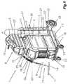
図1は、MIG/MAG溶接及び/又はTIG溶接又は電極溶接、ダブルワイヤ/タンデム溶接操作、プラズマ操作又はろう付け及びはんだ付け操作等の、多くの異なるプロセス及び/又は操作のための溶接装置1及び/又は溶接設備を示す。溶接装置1は、電力要素3がその中に配設された電源2、制御ユニット4、並びに、ワイヤ(不図示)、スイッチング部材、制御弁等のようなさらなる構成要素を含む。制御ユニット4は、特にCO2、ヘリウム、アルゴン等のようなシールドガスのガスボンベ6とガス供給ライン5の(溶接)トーチ7との間に配設された制御弁に接続されてもよい。FIG. 1 shows a
加えて、制御ユニット4は、さらなる材料及び/又は溶接ワイヤ9が供給ロール10及び又はワイヤコイルから供給ラインを介して溶接トーチ7の部分に供給される、MIG/MAG溶接で共用されるワイヤ供給ユニット8を制御するためにも使用されてもよい。勿論、ワイヤ供給ユニット8は、図1に示したように、カート12の上に配置された追加装置であるのと対照的に、従来技術から公知であるように、溶接装置1の中に、特に電源2のハウジングの中に組み込むことができる。これは、小型の溶接装置1と言及される。ここで、ワイヤ供給装置8は、溶接装置1の頂部に直接配置すること、つまり、電源2のハウジング11は、ワイヤ供給ユニット8を受け入れるために頂面が形成されて、カート12を省略できるようにすることもできる。さらに、ワイヤ供給ユニット8が、溶接ワイヤ及び/又は追加材料を溶接トーチ7の外側から溶接位置に供給するようにできる。その場合、TIG溶接において一般的であるように、好ましくは非溶融電極が溶接トーチ7内に配置される。 In addition, the control unit 4 provides a common wire supply for MIG / MAG welding in which further materials and / or
電極及び/又は溶接ワイヤ9と好ましくは1以上の部分からなる工作物14との間にアーク13、特に作業アークを生成するための電流は、電源2の電力要素3から溶接トーチ7、特に電極及び/又は溶接ワイは9に、溶接ライン(不図示)を介して供給され、さらなる可能性として、溶接すべき工作物14はさらなる溶接ライン(不図示)、特に帰還リードを介して電源2に接続され、形成されたアーク13及び/又はプラズマビームによって、プロセスのための電気回路を形成できる。内部アーク13を有するトーチを使用するとき、プラズマトーチの場合のように、適切な電気回路がトーチ内で完成できるように、両方の溶接ライン(不図示)はトーチに繋がる。 The current for generating an
溶接トーチ7を冷却するために、溶接トーチ7は、液体タンク、特に液面計17を備える水タンク16に、冷却装置15及び流量制御装置のような可能な中間構成要素を介して接続されてもよい。冷却装置15は、水タンク16内に位置する液体をために使用される液体ポンプが、溶接トーチ7の冷却を行うために、溶接トーチ7の起動に伴って始動する。図示した例示的実施形態に示すように、冷却装置15は、カート12の上に、電源2を配設する前に配置されている。溶接設備の個々の構成要素、つまり、電源、ワイヤ供給ユニット8及び冷却装置15は、それらを安全に積み上げ又は互いの頂部に配置できるように、それぞれ突起及び/又は凹部を有するように形成されている。 In order to cool the
溶接装置1、電源2は、特に、さらに、溶接装置2の全ての多様な溶接パラメータ、操作モード又は溶接プログラムを設定及び/又は読み込み及び表示するための入力及び/又は出力装置18を含む。入力及び/又は出力装置18により設定された溶接パラメータ、操作モード又は溶接プログラムは、制御ユニット4と通信され、そして、溶接設備及び/又は溶接装置1の個々の構成要素を駆動、及び/又は、調整又は制御のために対応する設定値を確定する。ここで、溶接トーチ7が溶接トーチ入力及び/又は出力装置19を具備する場合には、適切な溶接トーチ7を使用するときに、溶接トーチ7を介して設定手順を実行することもできる。この場合、溶接トーチ7は、好ましくは、溶接装置1、特に電源2又はワイヤ供給装置8に、データバス、特にシリアルデータバスを介して接続される。 The
溶接プロセスを開始するために、溶接トーチ7は、通常、スタートスイッチ(不図示)を含み、アーク13がスタートスイッチの操作によって点火される。アーク13の大きな熱放射からユーザを保護するために、溶接トーチ7は、熱保護シールド20を備えてもよい。さらに、図示した例示的実施形態において、溶接トーチ7は、溶接装置1及び/又は溶接設備にホースパック21を介して接続されており、前記ホースパック21は、座屈防止手段22により溶接トーチ7に取り付けられている。ホースパック21の中には、供給ライン及び/又は溶接ワイヤ9用、ガス5用、冷却回路用、データ転送用等のラインのような個々のラインが、溶接装置1から溶接トーチ7まで配設されているが、帰還リードは、好ましくは電源2まで別途接続される。ホースパック21は、電源2又はワイヤ供給ユニット8に接続装置(不図示)によって接続されるが、ホースパック21内の個々のラインは、溶接トーチ7へ又はその中に座屈防止手段によって取り付けられる。ホースパック21の適切な張力緩和を保証するために、ホースパック21は、電源2のハウジング11又はワイヤ供給ユニット8に張力緩和装置(不図示)を介して接続されてもよい。 In order to start the welding process, the
一般に、異なる溶接操作及び/又は、TIG装置、MIG/MAG装置又はプラズマ装置のような溶接装置1のために、上述の全ての構成要素が使用及び/又は組み込まれる必要はない。例えば、溶接トーチ7を空冷溶接トーチ7として形成したり、例えば、溶接トーチ7を省略することができるであろう。結果的に、溶接装置1は、少なくとも、電源2、ワイヤ供給ユニット8及び冷却装置15によって形成され、それらは共通のハウジング11の中に配設され得ると言える。さらに、ワイヤ供給ユニット8又はガスボンベ6のホルダ25の任意のキャリア21の引き摺り防止装置23等のさらなる部品及び/又は構成要素を配設及び/又は包含することができる。 In general, not all the components described above need to be used and / or incorporated for different welding operations and / or
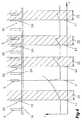
図2から5は、短絡溶接プロセスを図によって示し、そこでは、電流IがY軸に、そして、時間tがX軸に示されている。溶滴29及び/又は材料の移動が(概略図示したように)溶接ワイヤ9と溶融池及び/又は工作物16の間の短絡30によって達成される短絡溶接プロセス又は短絡アーク溶接プロセスの詳細な説明は、従来技術から広く知られているので含まれていない。 FIGS. 2 to 5 graphically illustrate the short-circuit welding process, where current I is shown on the Y axis and time t is shown on the X axis. Detailed description of a short-circuit welding process or a short-circuit arc welding process in which the
典型的には、短絡溶接において、電流Iは、短絡30が発生したときに増加する−図2の時間点31参照。ここで、短絡30が生じたときに電流Iの最初の低下と増加が可能である(不図示)。図示するように、電流Iは、増加した電流Iによる「ピンチ効果」を発生させることによって短絡30を切断するために、好ましくは予め設定した所定のタイムフレーム32(点線及びハッチングで図示)の中で連続的に増加する。短絡30を切断する間の溶接スパッタを可能な限り小さく形成することが重要である。短絡の切断により生じるスパッタの放出を最低限に維持するために、電流の増加を可能な限り低く設定しなければならない。つまり、電流増加di/dtは、電流増加の平坦な曲線を形成するために、図における時間点31からのタイムフレーム32内に見られるように、可能な限り低く選択されるが、溶接プロセスが比較的不安定になりやすいので、しばしば短絡30が所定のタイムフレーム31の中で切断されなくてもよい。この不安定性は、例えば、トーチの移動、つまり、溶接ワイヤ9の溶融池へのさらなる浸漬、溶融池内での上下動等により生じる。 Typically, in short circuit welding, the current I increases when a
短絡が切断される前にタイムフレーム32を超過すると、電流増加速度di/dtは、同じまま、又は、電流増加がより急になって、電流増加が速くなり、短絡30が早く遮断されることが、従来技術より知られている。 If the
本発明によれば、実行すべき短絡30の切断又は遮断のための特別な方法がここに提供される。図2の場合の時間点33において、短絡30が残っている間にタイムフレーム32を超過した後、例えば、電流、特に溶接電流、及び/又は電流プロファイルは、タイムフレーム32で使用される電流増加時間及び/又は速度di/dtよりも高い電流増加時間及び/又は速度di/dtで増加、特に、短絡30を切断及び/又は遮断するために指数的に増加する。同時に、電流増加時間及び/又は速度di/dtは、検出及び/又は監視され、短絡が切断されたときに、時間点34における電流増加時間及び/又は速度di/dtが記録される。結果として、−時間点35において−次に短絡30が生じている間の電流増加は、直前に保存した電流増加時間及び/又は速度di/dtにしたがって、タイムフレーム32の中で、短絡30が切断されてすぐ、つまり、時間点36において、電流増加時間及び/又は速度di/dtが、時間点31と時間点34との間のタイムフレームのdi/dtにしたがう初期値に再設定されて、タイムフレーム32の中で実行される。 According to the invention, a special method for cutting or breaking the
図2によると、一度タイムフレーム32が超過すると、時間点33から電流増加速度は予め設定できる最大値37まで徐々に増加し、そして、この最大値37が短絡30の遮断まで保持される。ここで利点は、電流増加がある閾値までに制限されて、非常に大きくはなり得ないので、大きな電流増加による過剰な溶接スパッタが防止されることである。それは、次の短絡30の間のタイムフレーム32の中で変更すべき電流増加速度の実質的重要性である。つまり、前の短絡30がタイムフレーム32を超過した後に残っていたならば、現在生じている短絡30の電流増加速度及び/又は時間di/dtは、以前に完了した短絡の切断に関して調節されている。 According to FIG. 2, once the
図2に示した例示的実施形態において、次のタイムフレーム32は、電流増加速度が初期値に再設定される前にタイムフレーム32を超過したなら、最初にタイムフレームを超過した後のように次のタイムフレーム32を超過しても調節される。勿論、超過の度に、次の値、特に電流増加速度及び/又は時間di/dtは、短絡30がタイムフレーム32の中で切断されるまで、前の短絡の値に関連して変更され、それにより、値又はパラメータは、次の短絡30の間に再設定され得る。これは、図示した例示的実施形態において、1回だけ、つまり、1つのタイムフレーム32において、或いは、以降のいくつかのタイムフレーム32に亘って、つまり、次のタイムフレーム32の間に1つのステップで完了する再設定をして実行されてもよい。 In the exemplary embodiment shown in FIG. 2, if the
しかしながら、もしも、図2に関して、すべてのタイムフレーム32の超過の後に次のタイムフレーム32において変更が実施される方法が使用されたなら、そのような手法は、タイムフレーム32の中で短絡が切断されるまでに再設定されていないタイムフレームのためのパラメータ、特に電流増加速度をもたらし、さもなくば、電流増加速度がそれぞれの新しいタイムフレーム32における前のパラメータに合わせられる。結果として、di/dtは、次の短絡30、特にタイムフレーム32のために、短絡30の時間が予め設定できる値に減少するまで、具体的には再度タイムフレーム32の中に収まるように、再び上昇させられる。しかしながら、電流増加速度は時間点34の短絡30の切断に対して調節されるので、タイムフレーム32の中の電流増加速度は、前のタイムフレーム32に関連して減少させられてもよい。このように、次の短絡30の場合よりも高い電流増加速度で切断を行うことができるので、タイムフレーム32における電流増加速度は増加しても減少してもよい。 However, with respect to FIG. 2, if a method is used in which changes are made in the
図3は、例示的実施形態を示し、そこでは、電流Iがもはや最大値37に制限されていないが、電流増加速度38が、予め設定され得、且つ、この電流増加速度38が時間点39に到達したときに見られた値に維持され、短絡が遮断されるまでの前記速度で増加する。電流Iとなる最大電流増加速度38に達すると、電流Iは、タイムフレーム31の中で新しい短絡30が生じるまで最大電流増加速度38で増加させられる。しかしながら、短絡30が再度タイムフレーム32の中で切断されなければ、電流増加は、常に最大電流増加速度38で、短絡30が切断されるまでのみ実行される。好ましくは、値又はパラメータは、タイムフレームが経過する度に、次のタイムフレーム32のために変更され、タイムフレーム32の中で短絡30が遮断されるまでは予め設定された値又はパラメータを再設定しない。完全性のために、可能な最大値よりも低いdi/dtでの短絡30の切断により、次の短絡30の間の電流は、先の短絡30の遮断の間に検出されたタイムフレーム32内の電流増加速度で増加させられることを注記する。 FIG. 3 shows an exemplary embodiment in which the current I is no longer limited to the
図4は、さらなる例示的実施形態を示し、そこでは、タイムフレーム32の超過後の値又はパラメータの再設定は、いくつかのタイムフレーム32を要する。ここでは、短絡30が時間点40において発生してタイムフレーム32が開始しており、電流Iは、予め設定されたであろう、特に、溶接スパッタを防止するために電流増加ができるだけ少ない電流増加速度で増加させられる。短絡30が所定のタイムフレーム32の中で切断されないので、電流増加速度の上昇及び特別な電流プロファイルが、短絡を切断するためにできるだけ早く行われる。電流プロファイルは、有り得る次のタイムフレーム32、つまり、他の短絡30のためのパラメータ又は値を検出又は調節するためにこの間に観測される。 FIG. 4 shows a further exemplary embodiment, where resetting a value or parameter after the
図4に示すように、短絡30は、時間点41において途切れ、電流が設定値、つまり作業電流まで低下し、時間点41における短絡30の切断において検出又は記録された値又はパラメータで、通常の短絡溶接操作を継続できる。時間点42では、短絡30が再度発生し、ここで、短絡30の切断のためのタイムフレーム内での電流プロファイルの変更が前の短絡30の値又はパラメータに基づいて行われる。好ましくは、現在実行されているタイムフレーム32内での電流増加速度は、直前の短絡30の切断の間(時間点41)の電流増加速度が適用される。しかしながら、メモリに記憶された使用すべき、非常に異なる曲線形状が直前の短絡の遮断に関係なく可能である。短絡の遮断の間の電流変化の速度の検出値に基づいて、例えば、対応する曲線形状、検出した電流増加速度又は異なるパラメータの割合及び/又は値等が割り当てられてもよく、これらの記録された値又はパラメータが次のタイムフレーム32のために使用される。例えば、電流増加は、1つのタイムフレーム32において線形に実行されるかもしれないが、先に実行したタイムフレーム32において短絡30がタイムフレーム32の中で途切れなかったなら、指数的電流増加を次のタイムフレーム32において実行してもよい。したがって、曲線の切り替えが、次のタイムフレームで行われてもよい。 As shown in FIG. 4, the
多段調節が図4に係る図示した例示的実施形態において実行され、短絡30は時間点42からのタイムフレーム32の中で遮断されるので、直前に記録した値又はパラメータは新しい短絡のために再度変更される。つまり、電流増加速度のある割合だけの減少が実行される。すなわち、もしも、時間点43に見られるように新しい短絡30が発生したなら、前の値又はパラメータから変更された電流プロファイルのためのある値及びパラメータで、タイムフレーム32が再び開始する。具体的には、前に実行されたプロファイルに比して低い電流増加速度が使用される。このように、値は実質的に、具体的には、例えば、時間点44に見られるような他の短絡30の場合に、値又はパラメータが初期値又は初期パラメータにリセットされた電流増加速度に低減される。結果として、タイムフレーム32を超過したとき、値又はパラメータは、多数の段階に亘って、段階的に減少させられる。図示した例示的実施形態では2つの段階が示されているが、より多くの段階も可能である。 Since the multi-stage adjustment is performed in the illustrated exemplary embodiment according to FIG. 4 and the
さらなる例示的実施形態が図5に示され、そこでは、電流増加速度ではなく絡30が遮断されたときの継続時間45が検出及び監視され、それにより、対応する変更が次のタイムフレーム32においてなされる。ここでは、タイムフレーム32に繋がる時間点46において短絡30が発生し、短絡30を遮断するために、タイムフレーム32内において電流が予め設定した電流増加速度で直線的に増加させられる。しかしながら、短絡はタイムフレームの終わりに遮断されていないので、電流はさらに増加する。具体的には、短絡30を早く遮断するために電流プロファイルの指数的又は直線的上昇が実行される。この場合、継続時間45は、短絡30が遮断されるまで監視及び/又は検出される。つまり、継続時間45は、一度タイムフレーム32を超過すると測定され、次のタイムフレーム32のために、記録された関数、表又は値にしたがって、値又はパラメータ、特に電流増加速度の変更が行われる。新しい短絡30が発生すると、時間点47の場合のように、予め設定された値又はパラメータについて変更されているタイムフレーム32の中の値又はパラメータでタイムフレームを開始する。好ましくは、時間点47からのタイムフレーム32において見られるように、前に超過した継続時間45にしたがう割合による電流増加速度の調節がなされる。 A further exemplary embodiment is shown in FIG. 5, where the
さらに、図示した例示的実施形態において、値又はパラメータを低下、特に、電流増加速度di/dtを低下させることも可能である。これは、実施形態に示すように、今、タイムフレーム32が超過する前に短絡が遮断された、予め設定された値又はパラメータで実行されているタイムフレーム32の中の電流プロファイルで、時間点48において生じた短絡30によってなし得る。既に上述したように、継続時間45は、タイムフレーム32の超過に関して短絡30の遮断のための正確な瞬間を確定できるように検出される。ここで、継続時間45の残余時間は、短絡30が遮断されたときにタイムフレーム32に使用されることができ、或いは、継続時間45は、タイムフレーム32とともにその開始の間に検出されることができる。短絡30の遮断が、今、予め設定した初期値で実行されているので、これらの値、特に電流増加速度は、時間点49からのタイムフレーム32内の次の短絡30の間の(時間点48で開始する)電流プロファイルを、前のタイムフレーム32よりも低減するために減少させられる。 Furthermore, in the illustrated exemplary embodiment, it is also possible to reduce the value or parameter, in particular the current increase rate di / dt. This is a current profile in a
しかしながら、電流増加速度を次の短絡30のために実際の短絡の継続時間と予め設定できる意図される短絡の継続時間との差に応じて変更することもできる。例えば、di/dtは、短絡30が予め設定した継続時間よりも長い継続時間を有するときに増加させられ、及び/又は、di/dtは、短絡30が予め設定した時間よりも短いときに減少させられる。 However, the rate of current increase can also be varied depending on the difference between the actual short-circuit duration and the intended short-circuit duration that can be preset for the next short-
したがって、短絡アーク溶接の間に短絡を切断するために使用される方法において、タイムフレーム32は短絡30が発生したときに開始する。そのタイムフレーム32において、タイムフレーム32の中で短絡30を遮断するために確定された電流プロファイルが実行され、タイムフレーム32を超過したら、短絡30の間にタイムフレームを超過した後に検出されたこの短絡30を切断するための電流プロファイルで電流の増加が実行される。これにより、短絡30が切断されたとき、少なくとも1つの値又はパラメータが記録又は保存される、次の短絡30のタイムフレーム32の中の少なくとも1つの値又はパラメータが、記録された値又はパラメータに応じて調節される。一方、従来技術においては、電流増加は、所定の短絡の時間、つまり、所定のタイムフレームを超過した後、短絡が遮断されるまで固定された高い値に変更される。その後、新しい短絡が生じたときに遮断手順が予め設定した値で開始されるように、パラメータは再度リセットされるが、本発明に係る解決策では、新しい短絡の事象において、値は、短絡を遮断したときの前の値に調節、つまり、短絡30の切断のための所定のタイムフレーム32を超過又は短すぎるならは、短絡アーク溶接の間の短絡を切断するための方法で次のタイムフレームの値又はパラメータの変更が実行される。プロセス状況の詳細な概略は、従来技術から既に知られているように、これに関して与えられる。 Thus, in the method used to break the short circuit during short circuit arc welding, the
電流増加速度は、短絡30の開始点、つまり、タイムフレーム32の開始から、直線的又は如何なる予め設定できる関数にしたがっても、単調に上昇してもよく、これは、タイムフレームを超過した後に同じ又は変更した態様で継続してもよい。しかしながら、遮断の瞬間に基づいて、変更は、次の短絡、つまり、次のタイムフレーム32のために再度なされてもよい。さらに、短絡の発生が不確定又は任意であり、短絡30が特定されたときだけタイムフレーム32が開始することを維持しなければならない。しかしながら、短絡が特定された所定のときに、それが「飽和した」短絡30であるか、又は、溶接ワイヤ9が短時間だけ溶融池に浸かっているだけであるかを判定するために、短絡の状態を監視するこがができる。短絡30があることを確認した後だけ、タイムフレーム32を開始及び/又は継続する。 The rate of current increase may increase monotonically from the start of the
最後に、例示的実施形態は、本発明を具体的に示した実施形態に限定することなく、単に本発明に係る解決策を実施するための可能な方法を示すことを意図することに注意しなければならない。特に、個々の実施形態の組み合わせも可能であり、そこでの変形の可能性は、本発明の技術的作用が教唆するので、当業者の裁量である。本発明の保護範囲は、さらに、全ての実現可能な、本発明が基にする、明確に説明又は図示していない解決策を実現する本発明、及び、図示して記載した実施形態の個々の細部の組み合わせにより可能な発明を実施する方法をカバーする。さらに、保護範囲は、権利範囲の発明を実施するために必要である限り、本発明に係る装置の個々の構成要素をカバーする。 Finally, it should be noted that the exemplary embodiments are not intended to limit the invention to the specifically illustrated embodiments, but merely to show possible ways to implement the solution according to the invention. There must be. In particular, combinations of the individual embodiments are possible, and the possibility of variations therein is at the discretion of those skilled in the art since the technical action of the present invention is taught. The scope of protection of the present invention further includes all possible realizations of the invention on which the invention is based, the solutions that are not explicitly described or illustrated, and the individual embodiments of the illustrated and described embodiments. Covers possible ways of practicing the invention by combining details. Furthermore, the protective scope covers the individual components of the device according to the invention, as long as it is necessary to carry out the scope of the invention.
Claims (11)
Translated fromJapaneseApplications Claiming Priority (3)
| Application Number | Priority Date | Filing Date | Title |
|---|---|---|---|
| AT12602009AAT508146B1 (en) | 2009-08-10 | 2009-08-10 | METHOD FOR DISCONNECTING A SHORT CIRCUIT FOR SHORT ARC WELDING AND WELDING DEVICE FOR SHORT ARC WELDING |
| ATA1260/2009 | 2009-08-10 | ||
| PCT/AT2010/000272WO2011017725A1 (en) | 2009-08-10 | 2010-07-23 | Method for disconnecting a short circuit during short-arc welding and welding device for short-arc welding |
Publications (2)
| Publication Number | Publication Date |
|---|---|
| JP2013501620Atrue JP2013501620A (en) | 2013-01-17 |
| JP5628917B2 JP5628917B2 (en) | 2014-11-19 |
Family
ID=43027477
Family Applications (1)
| Application Number | Title | Priority Date | Filing Date |
|---|---|---|---|
| JP2012524047AActiveJP5628917B2 (en) | 2009-08-10 | 2010-07-23 | Method of cutting short circuit during short circuit arc welding and welding apparatus for short circuit arc welding |
Country Status (8)
| Country | Link |
|---|---|
| US (1) | US9035218B2 (en) |
| EP (1) | EP2464488B1 (en) |
| JP (1) | JP5628917B2 (en) |
| CN (1) | CN102470475B (en) |
| AT (1) | AT508146B1 (en) |
| BR (1) | BR112012002899A2 (en) |
| RU (1) | RU2502587C2 (en) |
| WO (1) | WO2011017725A1 (en) |
Families Citing this family (12)
| Publication number | Priority date | Publication date | Assignee | Title |
|---|---|---|---|---|
| EP2505294B1 (en) | 2010-10-07 | 2016-08-31 | Panasonic Intellectual Property Management Co., Ltd. | Arc welding method and arc welding device |
| US20130264323A1 (en)* | 2012-04-05 | 2013-10-10 | Lincoln Global, Inc. | Process for surface tension transfer short ciruit welding |
| US11370051B2 (en)* | 2018-10-30 | 2022-06-28 | Lincoln Global, Inc. | Time-based short circuit response |
| US20220009018A1 (en)* | 2018-11-08 | 2022-01-13 | Matt Pixley | System and method for controlling welding machine |
| US20200238418A1 (en)* | 2019-01-24 | 2020-07-30 | Illinois Tool Works Inc. | Systems and methods with integrated switch for controlled short circuit welding processes |
| CN109909587B (en)* | 2019-03-20 | 2023-12-22 | 浙江肯得机电股份有限公司 | Double MCU digital PI and PWM control multifunctional welding machine |
| CN111001908B (en)* | 2019-12-26 | 2021-09-17 | 唐山松下产业机器有限公司 | Consumable electrode pulse welding method, consumable electrode pulse welding system and consumable electrode pulse welding machine |
| WO2021140970A1 (en)* | 2020-01-06 | 2021-07-15 | パナソニックIpマネジメント株式会社 | Arc welding control method and arc welding device |
| US12194574B2 (en) | 2021-09-02 | 2025-01-14 | Lincoln Global, Inc. | System and method for adapting break point for short circuit welding |
| CN116748648B (en)* | 2023-05-31 | 2025-09-30 | 湖南恒岳重钢钢结构工程有限公司 | A method for adaptively adjusting current and voltage of an inner ring weld welding carriage |
| CN118023789B (en)* | 2024-04-11 | 2024-07-02 | 山东宏跃网架钢结构有限公司 | Efficient and safe assembly type building welding device and method |
| CN119140949B (en)* | 2024-09-03 | 2025-09-30 | 华南理工大学 | Wire feeding adaptive adjustment method and welding system based on high-frequency MIG welding |
Citations (7)
| Publication number | Priority date | Publication date | Assignee | Title |
|---|---|---|---|---|
| JPS4965355A (en)* | 1972-08-24 | 1974-06-25 | ||
| JPS50112245A (en)* | 1974-02-14 | 1975-09-03 | ||
| JPS6064774A (en)* | 1983-04-30 | 1985-04-13 | Kobe Steel Ltd | Method for controlling current of welding accompanying short-circuit transfer |
| JPH01162573A (en)* | 1987-12-18 | 1989-06-27 | Hitachi Seiko Ltd | Arc welding power source |
| JPH02160172A (en)* | 1988-11-14 | 1990-06-20 | Lincoln Electric Co:The | Apparatus and method for short |
| JPH0366473A (en)* | 1987-12-21 | 1991-03-22 | Lincoln Electric Co:The | Device and method for short circuiting arc welding |
| JPH09271941A (en)* | 1996-04-09 | 1997-10-21 | Hitachi Seiko Ltd | Power source for arc welding |
Family Cites Families (12)
| Publication number | Priority date | Publication date | Assignee | Title |
|---|---|---|---|---|
| GB1109901A (en)* | 1964-07-14 | 1968-04-18 | Lincoln Electric Company Ltd | Improvements in electric arc welding apparatus |
| US4546234A (en)* | 1983-08-11 | 1985-10-08 | Kabushiki Kaisha Kobe Seiko Sho | Output control of short circuit welding power source |
| SU1826338A1 (en)* | 1989-12-19 | 1996-08-27 | Научно-производственное объединение НИКИМТ | Method for dip-transfer arc welding |
| US6087626A (en) | 1998-02-17 | 2000-07-11 | Illinois Tool Works Inc. | Method and apparatus for welding |
| US6617549B2 (en) | 2001-12-06 | 2003-09-09 | Illinois Tool Works Inc. | Method and apparatus for welding with restrike |
| US6969823B2 (en) | 2002-07-23 | 2005-11-29 | Illinois Tool Works Inc. | Method and apparatus for controlling a welding system |
| RU2220034C1 (en)* | 2003-01-30 | 2003-12-27 | Закрытое акционерное общество Научно-производственная фирма "Инженерный и технологический сервис" | Method for electric arc welding with short circuiting of arc gap and power source for performing the same |
| US7173214B2 (en) | 2004-04-01 | 2007-02-06 | Lincoln Global, Inc. | Electric arc pulse welder with short circuit control |
| US8203099B2 (en) | 2004-06-04 | 2012-06-19 | Lincoln Global, Inc. | Method and device to build-up, clad, or hard-face with minimal admixture |
| JP3941802B2 (en) | 2004-07-08 | 2007-07-04 | 松下電器産業株式会社 | Arc welding control method and arc welding apparatus |
| RU2268809C1 (en)* | 2004-08-04 | 2006-01-27 | Томский политехнический университет | Electric arc welding method by means of consumable electrode with pulse modulation of current |
| WO2008137371A2 (en) | 2007-04-30 | 2008-11-13 | Illinois Tool Works Inc. | Welding system and method with improved waveform |
- 2009
- 2009-08-10ATAT12602009Apatent/AT508146B1/ennot_activeIP Right Cessation
- 2010
- 2010-07-23JPJP2012524047Apatent/JP5628917B2/enactiveActive
- 2010-07-23CNCN201080035104.6Apatent/CN102470475B/enactiveActive
- 2010-07-23USUS13/389,064patent/US9035218B2/enactiveActive
- 2010-07-23BRBR112012002899Apatent/BR112012002899A2/ennot_activeIP Right Cessation
- 2010-07-23EPEP10739289.6Apatent/EP2464488B1/enactiveActive
- 2010-07-23RURU2012108712/02Apatent/RU2502587C2/ennot_activeIP Right Cessation
- 2010-07-23WOPCT/AT2010/000272patent/WO2011017725A1/enactiveApplication Filing
Patent Citations (7)
| Publication number | Priority date | Publication date | Assignee | Title |
|---|---|---|---|---|
| JPS4965355A (en)* | 1972-08-24 | 1974-06-25 | ||
| JPS50112245A (en)* | 1974-02-14 | 1975-09-03 | ||
| JPS6064774A (en)* | 1983-04-30 | 1985-04-13 | Kobe Steel Ltd | Method for controlling current of welding accompanying short-circuit transfer |
| JPH01162573A (en)* | 1987-12-18 | 1989-06-27 | Hitachi Seiko Ltd | Arc welding power source |
| JPH0366473A (en)* | 1987-12-21 | 1991-03-22 | Lincoln Electric Co:The | Device and method for short circuiting arc welding |
| JPH02160172A (en)* | 1988-11-14 | 1990-06-20 | Lincoln Electric Co:The | Apparatus and method for short |
| JPH09271941A (en)* | 1996-04-09 | 1997-10-21 | Hitachi Seiko Ltd | Power source for arc welding |
Also Published As
| Publication number | Publication date |
|---|---|
| US20120132632A1 (en) | 2012-05-31 |
| JP5628917B2 (en) | 2014-11-19 |
| AT508146B1 (en) | 2010-11-15 |
| CN102470475A (en) | 2012-05-23 |
| WO2011017725A1 (en) | 2011-02-17 |
| AT508146A4 (en) | 2010-11-15 |
| RU2502587C2 (en) | 2013-12-27 |
| CN102470475B (en) | 2014-09-24 |
| EP2464488A1 (en) | 2012-06-20 |
| US9035218B2 (en) | 2015-05-19 |
| BR112012002899A2 (en) | 2016-04-05 |
| RU2012108712A (en) | 2013-09-20 |
| EP2464488B1 (en) | 2014-06-11 |
Similar Documents
| Publication | Publication Date | Title |
|---|---|---|
| JP5628917B2 (en) | Method of cutting short circuit during short circuit arc welding and welding apparatus for short circuit arc welding | |
| US8389900B2 (en) | Method for welding a workpiece | |
| US9089920B2 (en) | Method for changing a welding process during a welding operation and method for applying heat prior to a welding operation | |
| JP3652350B2 (en) | Plasma processing method | |
| US20060207979A1 (en) | Method and apparatus for advance warning and controlled shutdown in an arc processing system | |
| JP4422729B2 (en) | How to control the welding process | |
| US20040262280A1 (en) | Arc welding method | |
| KR20050097448A (en) | Electric arc pulse welder with short circuit control | |
| CN109641310B (en) | Arc stopping | |
| CN116060736A (en) | Control method for realizing MIGAC arc and ColdARC arc | |
| WO2017038060A1 (en) | Arc welding method and arc welding device | |
| JP2006122957A (en) | Output control method for welding source | |
| CN114641364B (en) | Method and apparatus for welding a weld | |
| JP2009226443A (en) | Arc start control method for two-electrode arc welding | |
| JP4934363B2 (en) | Arc welding machine control method and arc welding machine | |
| KR101860947B1 (en) | Welding Arc Regeneration Expectation Method for Reduction Spatter | |
| JPS60108174A (en) | Output controlling method of welding electric power source | |
| JP2008229705A (en) | Plasma gma welding torch and plasma gma welding method | |
| JP4776868B2 (en) | Method used in gas shielded metal arc welding | |
| JP2016520003A (en) | Welding control method | |
| KR100668233B1 (en) | Waveform control method for high speed welding | |
| JP6027887B2 (en) | Touch start control method for non-consumable electrode arc welding | |
| JP2005028380A (en) | Retract arc start control method for consumable electrode arc welding | |
| KR101572433B1 (en) | Overload release, in particular for a circuit breaker | |
| JP2010247224A (en) | Arc welding method |
Legal Events
| Date | Code | Title | Description |
|---|---|---|---|
| A601 | Written request for extension of time | Free format text:JAPANESE INTERMEDIATE CODE: A601 Effective date:20130910 | |
| A602 | Written permission of extension of time | Free format text:JAPANESE INTERMEDIATE CODE: A602 Effective date:20130918 | |
| A521 | Request for written amendment filed | Free format text:JAPANESE INTERMEDIATE CODE: A523 Effective date:20131011 | |
| A131 | Notification of reasons for refusal | Free format text:JAPANESE INTERMEDIATE CODE: A131 Effective date:20140311 | |
| A521 | Request for written amendment filed | Free format text:JAPANESE INTERMEDIATE CODE: A523 Effective date:20140603 | |
| TRDD | Decision of grant or rejection written | ||
| A01 | Written decision to grant a patent or to grant a registration (utility model) | Free format text:JAPANESE INTERMEDIATE CODE: A01 Effective date:20140916 | |
| A61 | First payment of annual fees (during grant procedure) | Free format text:JAPANESE INTERMEDIATE CODE: A61 Effective date:20141002 | |
| R150 | Certificate of patent or registration of utility model | Ref document number:5628917 Country of ref document:JP Free format text:JAPANESE INTERMEDIATE CODE: R150 | |
| R250 | Receipt of annual fees | Free format text:JAPANESE INTERMEDIATE CODE: R250 | |
| R250 | Receipt of annual fees | Free format text:JAPANESE INTERMEDIATE CODE: R250 | |
| R250 | Receipt of annual fees | Free format text:JAPANESE INTERMEDIATE CODE: R250 | |
| R250 | Receipt of annual fees | Free format text:JAPANESE INTERMEDIATE CODE: R250 | |
| R250 | Receipt of annual fees | Free format text:JAPANESE INTERMEDIATE CODE: R250 | |
| R250 | Receipt of annual fees | Free format text:JAPANESE INTERMEDIATE CODE: R250 | |
| R250 | Receipt of annual fees | Free format text:JAPANESE INTERMEDIATE CODE: R250 | |
| R250 | Receipt of annual fees | Free format text:JAPANESE INTERMEDIATE CODE: R250 |