JP2013500109A - Apparatus and method for brain fiber bundle microscopy - Google Patents
Apparatus and method for brain fiber bundle microscopyDownload PDFInfo
- Publication number
- JP2013500109A JP2013500109AJP2012522278AJP2012522278AJP2013500109AJP 2013500109 AJP2013500109 AJP 2013500109AJP 2012522278 AJP2012522278 AJP 2012522278AJP 2012522278 AJP2012522278 AJP 2012522278AJP 2013500109 AJP2013500109 AJP 2013500109A
- Authority
- JP
- Japan
- Prior art keywords
- fiber bundle
- implant
- animal
- base support
- brain
- Prior art date
- Legal status (The legal status is an assumption and is not a legal conclusion. Google has not performed a legal analysis and makes no representation as to the accuracy of the status listed.)
- Granted
Links
- 239000000835fiberSubstances0.000titleclaimsabstractdescription162
- 210000004556brainAnatomy0.000titleclaimsabstractdescription65
- 238000000034methodMethods0.000titleclaimsdescription18
- 238000000386microscopyMethods0.000titleclaimsdescription7
- 239000007943implantSubstances0.000claimsabstractdescription89
- 241001465754MetazoaSpecies0.000claimsabstractdescription73
- 210000003625skullAnatomy0.000claimsabstractdescription32
- 238000007917intracranial administrationMethods0.000claimsabstractdescription19
- 239000000523sampleSubstances0.000claimsdescription55
- 238000003384imaging methodMethods0.000claimsdescription9
- 239000011248coating agentSubstances0.000claimsdescription4
- 238000000576coating methodMethods0.000claimsdescription4
- 239000013307optical fiberSubstances0.000claimsdescription4
- 238000013519translationMethods0.000claimsdescription4
- 239000003479dental cementSubstances0.000claimsdescription3
- 230000005540biological transmissionEffects0.000claims1
- 238000005553drillingMethods0.000claims1
- 230000000149penetrating effectEffects0.000abstractdescription4
- 238000005498polishingMethods0.000description18
- 241000699666Mus <mouse, genus>Species0.000description17
- 239000000853adhesiveSubstances0.000description6
- 230000001070adhesive effectEffects0.000description6
- 238000000799fluorescence microscopyMethods0.000description5
- 230000001537neural effectEffects0.000description4
- 238000002610neuroimagingMethods0.000description4
- 230000008901benefitEffects0.000description3
- 230000001684chronic effectEffects0.000description3
- 238000011835investigationMethods0.000description3
- 238000001727in vivoMethods0.000description2
- 238000010859live-cell imagingMethods0.000description2
- 230000007246mechanismEffects0.000description2
- 208000033999Device damageDiseases0.000description1
- 108010043121Green Fluorescent ProteinsProteins0.000description1
- 102000004144Green Fluorescent ProteinsHuman genes0.000description1
- 241000699670Mus sp.Species0.000description1
- 206010062519Poor quality sleepDiseases0.000description1
- 230000009471actionEffects0.000description1
- 238000013528artificial neural networkMethods0.000description1
- 210000003169central nervous systemAnatomy0.000description1
- 238000001218confocal laser scanning microscopyMethods0.000description1
- 238000010586diagramMethods0.000description1
- 238000002474experimental methodMethods0.000description1
- 239000005090green fluorescent proteinSubstances0.000description1
- 230000006872improvementEffects0.000description1
- 238000011065in-situ storageMethods0.000description1
- 238000003780insertionMethods0.000description1
- 230000037431insertionEffects0.000description1
- 230000007774longtermEffects0.000description1
- 238000002595magnetic resonance imagingMethods0.000description1
- 239000007769metal materialSubstances0.000description1
- 230000008439repair processEffects0.000description1
- 238000011160researchMethods0.000description1
- 230000035945sensitivityEffects0.000description1
- 229910001220stainless steelInorganic materials0.000description1
- 239000010935stainless steelSubstances0.000description1
- 238000001356surgical procedureMethods0.000description1
- 230000002123temporal effectEffects0.000description1
- 210000001519tissueAnatomy0.000description1
- 238000011830transgenic mouse modelMethods0.000description1
Images


Classifications
- A—HUMAN NECESSITIES
- A61—MEDICAL OR VETERINARY SCIENCE; HYGIENE
- A61B—DIAGNOSIS; SURGERY; IDENTIFICATION
- A61B5/00—Measuring for diagnostic purposes; Identification of persons
- A61B5/0059—Measuring for diagnostic purposes; Identification of persons using light, e.g. diagnosis by transillumination, diascopy, fluorescence
- A61B5/0082—Measuring for diagnostic purposes; Identification of persons using light, e.g. diagnosis by transillumination, diascopy, fluorescence adapted for particular medical purposes
- A61B5/0084—Measuring for diagnostic purposes; Identification of persons using light, e.g. diagnosis by transillumination, diascopy, fluorescence adapted for particular medical purposes for introduction into the body, e.g. by catheters
- A—HUMAN NECESSITIES
- A61—MEDICAL OR VETERINARY SCIENCE; HYGIENE
- A61B—DIAGNOSIS; SURGERY; IDENTIFICATION
- A61B1/00—Instruments for performing medical examinations of the interior of cavities or tubes of the body by visual or photographical inspection, e.g. endoscopes; Illuminating arrangements therefor
- A61B1/00147—Holding or positioning arrangements
- A61B1/00154—Holding or positioning arrangements using guiding arrangements for insertion
- A—HUMAN NECESSITIES
- A61—MEDICAL OR VETERINARY SCIENCE; HYGIENE
- A61B—DIAGNOSIS; SURGERY; IDENTIFICATION
- A61B5/00—Measuring for diagnostic purposes; Identification of persons
- A61B5/68—Arrangements of detecting, measuring or recording means, e.g. sensors, in relation to patient
- A61B5/6801—Arrangements of detecting, measuring or recording means, e.g. sensors, in relation to patient specially adapted to be attached to or worn on the body surface
- A61B5/6813—Specially adapted to be attached to a specific body part
- A61B5/6814—Head
- A—HUMAN NECESSITIES
- A61—MEDICAL OR VETERINARY SCIENCE; HYGIENE
- A61B—DIAGNOSIS; SURGERY; IDENTIFICATION
- A61B5/00—Measuring for diagnostic purposes; Identification of persons
- A61B5/68—Arrangements of detecting, measuring or recording means, e.g. sensors, in relation to patient
- A61B5/6846—Arrangements of detecting, measuring or recording means, e.g. sensors, in relation to patient specially adapted to be brought in contact with an internal body part, i.e. invasive
- A61B5/6847—Arrangements of detecting, measuring or recording means, e.g. sensors, in relation to patient specially adapted to be brought in contact with an internal body part, i.e. invasive mounted on an invasive device
- A61B5/6864—Burr holes
- A—HUMAN NECESSITIES
- A61—MEDICAL OR VETERINARY SCIENCE; HYGIENE
- A61B—DIAGNOSIS; SURGERY; IDENTIFICATION
- A61B5/00—Measuring for diagnostic purposes; Identification of persons
- A61B5/68—Arrangements of detecting, measuring or recording means, e.g. sensors, in relation to patient
- A61B5/6846—Arrangements of detecting, measuring or recording means, e.g. sensors, in relation to patient specially adapted to be brought in contact with an internal body part, i.e. invasive
- A61B5/6867—Arrangements of detecting, measuring or recording means, e.g. sensors, in relation to patient specially adapted to be brought in contact with an internal body part, i.e. invasive specially adapted to be attached or implanted in a specific body part
- A61B5/6868—Brain
- A—HUMAN NECESSITIES
- A61—MEDICAL OR VETERINARY SCIENCE; HYGIENE
- A61B—DIAGNOSIS; SURGERY; IDENTIFICATION
- A61B5/00—Measuring for diagnostic purposes; Identification of persons
- A61B5/68—Arrangements of detecting, measuring or recording means, e.g. sensors, in relation to patient
- A61B5/6846—Arrangements of detecting, measuring or recording means, e.g. sensors, in relation to patient specially adapted to be brought in contact with an internal body part, i.e. invasive
- A61B5/6879—Means for maintaining contact with the body
- A61B5/6882—Anchoring means
- A—HUMAN NECESSITIES
- A61—MEDICAL OR VETERINARY SCIENCE; HYGIENE
- A61B—DIAGNOSIS; SURGERY; IDENTIFICATION
- A61B90/00—Instruments, implements or accessories specially adapted for surgery or diagnosis and not covered by any of the groups A61B1/00 - A61B50/00, e.g. for luxation treatment or for protecting wound edges
- A61B90/10—Instruments, implements or accessories specially adapted for surgery or diagnosis and not covered by any of the groups A61B1/00 - A61B50/00, e.g. for luxation treatment or for protecting wound edges for stereotaxic surgery, e.g. frame-based stereotaxis
- A61B90/11—Instruments, implements or accessories specially adapted for surgery or diagnosis and not covered by any of the groups A61B1/00 - A61B50/00, e.g. for luxation treatment or for protecting wound edges for stereotaxic surgery, e.g. frame-based stereotaxis with guides for needles or instruments, e.g. arcuate slides or ball joints
- G—PHYSICS
- G02—OPTICS
- G02B—OPTICAL ELEMENTS, SYSTEMS OR APPARATUS
- G02B23/00—Telescopes, e.g. binoculars; Periscopes; Instruments for viewing the inside of hollow bodies; Viewfinders; Optical aiming or sighting devices
- G02B23/24—Instruments or systems for viewing the inside of hollow bodies, e.g. fibrescopes
- G02B23/26—Instruments or systems for viewing the inside of hollow bodies, e.g. fibrescopes using light guides
- A—HUMAN NECESSITIES
- A61—MEDICAL OR VETERINARY SCIENCE; HYGIENE
- A61B—DIAGNOSIS; SURGERY; IDENTIFICATION
- A61B1/00—Instruments for performing medical examinations of the interior of cavities or tubes of the body by visual or photographical inspection, e.g. endoscopes; Illuminating arrangements therefor
- A61B1/313—Instruments for performing medical examinations of the interior of cavities or tubes of the body by visual or photographical inspection, e.g. endoscopes; Illuminating arrangements therefor for introducing through surgical openings, e.g. laparoscopes
- A—HUMAN NECESSITIES
- A61—MEDICAL OR VETERINARY SCIENCE; HYGIENE
- A61B—DIAGNOSIS; SURGERY; IDENTIFICATION
- A61B2503/00—Evaluating a particular growth phase or type of persons or animals
- A61B2503/40—Animals
- A—HUMAN NECESSITIES
- A61—MEDICAL OR VETERINARY SCIENCE; HYGIENE
- A61B—DIAGNOSIS; SURGERY; IDENTIFICATION
- A61B2560/00—Constructional details of operational features of apparatus; Accessories for medical measuring apparatus
- A61B2560/06—Accessories for medical measuring apparatus
- A61B2560/063—Devices specially adapted for delivering implantable medical measuring apparatus
- A—HUMAN NECESSITIES
- A61—MEDICAL OR VETERINARY SCIENCE; HYGIENE
- A61B—DIAGNOSIS; SURGERY; IDENTIFICATION
- A61B2562/00—Details of sensors; Constructional details of sensor housings or probes; Accessories for sensors
- A61B2562/02—Details of sensors specially adapted for in-vivo measurements
- A61B2562/0233—Special features of optical sensors or probes classified in A61B5/00
- A61B2562/0238—Optical sensor arrangements for performing transmission measurements on body tissue
- A—HUMAN NECESSITIES
- A61—MEDICAL OR VETERINARY SCIENCE; HYGIENE
- A61B—DIAGNOSIS; SURGERY; IDENTIFICATION
- A61B5/00—Measuring for diagnostic purposes; Identification of persons
- A61B5/0059—Measuring for diagnostic purposes; Identification of persons using light, e.g. diagnosis by transillumination, diascopy, fluorescence
- A61B5/0062—Arrangements for scanning
- A61B5/0068—Confocal scanning
- A—HUMAN NECESSITIES
- A61—MEDICAL OR VETERINARY SCIENCE; HYGIENE
- A61B—DIAGNOSIS; SURGERY; IDENTIFICATION
- A61B5/00—Measuring for diagnostic purposes; Identification of persons
- A61B5/0059—Measuring for diagnostic purposes; Identification of persons using light, e.g. diagnosis by transillumination, diascopy, fluorescence
- A61B5/0071—Measuring for diagnostic purposes; Identification of persons using light, e.g. diagnosis by transillumination, diascopy, fluorescence by measuring fluorescence emission
Landscapes
- Health & Medical Sciences (AREA)
- Life Sciences & Earth Sciences (AREA)
- Physics & Mathematics (AREA)
- Surgery (AREA)
- Veterinary Medicine (AREA)
- Engineering & Computer Science (AREA)
- Biomedical Technology (AREA)
- Heart & Thoracic Surgery (AREA)
- Medical Informatics (AREA)
- Molecular Biology (AREA)
- Animal Behavior & Ethology (AREA)
- General Health & Medical Sciences (AREA)
- Public Health (AREA)
- Pathology (AREA)
- Biophysics (AREA)
- Optics & Photonics (AREA)
- Nuclear Medicine, Radiotherapy & Molecular Imaging (AREA)
- Radiology & Medical Imaging (AREA)
- Astronomy & Astrophysics (AREA)
- General Physics & Mathematics (AREA)
- Oral & Maxillofacial Surgery (AREA)
- Neurology (AREA)
- Endoscopes (AREA)
- Electrotherapy Devices (AREA)
- Magnetic Resonance Imaging Apparatus (AREA)
- Laser Surgery Devices (AREA)
- Surgical Instruments (AREA)
- Measurement And Recording Of Electrical Phenomena And Electrical Characteristics Of The Living Body (AREA)
- Prostheses (AREA)
- Apparatus Associated With Microorganisms And Enzymes (AREA)
- Measurement Of The Respiration, Hearing Ability, Form, And Blood Characteristics Of Living Organisms (AREA)
Abstract
Translated fromJapaneseDescription
Translated fromJapanese本開示は、動物の脳イメージングに関する。特に、本開示は、覚醒状態で行動する動物の脳イメージングに関する。 The present disclosure relates to animal brain imaging. In particular, the present disclosure relates to brain imaging of animals that behave in wakefulness.
小動物の脳イメージングは種々の方法で実施されうるが、研究者にとって、中枢神経系の選択された部位を、その神経構造の機能を画像化するのに十分な空間分解能及び時間分解能で観察可能とする方法は、少数でしかない。 Small animal brain imaging can be performed in a variety of ways, allowing researchers to observe selected parts of the central nervous system with sufficient spatial and temporal resolution to image the function of their neural structures. There are only a few ways to do this.
実際に、磁気共鳴イメージング及びスキャナイメージングの方法は概して低分解能の画像をもたらすため、活性化された脳部位に関する機能情報を利用可能であるにすぎない。脳の電気的な感度を分析するために脳に直接挿入される電極を使用する方法は、電極の位置決めに厳密な正確さが要求され、かつ結果として得られる電気信号の解釈が複雑であることが妨げとなっている。 In fact, magnetic resonance imaging and scanner imaging methods generally provide low resolution images, so only functional information about the activated brain region is available. The method of using electrodes directly inserted into the brain to analyze the electrical sensitivity of the brain requires precise positioning of the electrodes and complex interpretation of the resulting electrical signal Is a hindrance.
顕微鏡法が脳イメージングに有用であることが証明されつつある。死んだ動物の脳切片の顕微鏡観察はよく知られているが、生きている動物のインビボでの顕微鏡観察は最近のテーマである。歴史的に見て、インビボの顕微鏡法で脳の深部領域を分析することができなかったのは、満足な分解能のある技術がないか、あるいは過度の侵襲的手術を要したからである。本出願人は、無傷のマウス脳の光ファイバ式機能イメージングのための提案を述べている(ヴィンセントほか(Vincent et al.)、「ファイバ式蛍光顕微鏡法による神経構造及び機能のライブイメージング」(Live imaging of neural structure and function by fibred fluorescence microscopy)、イーエムビーオーレポーツ(EMBO reports)、2006年9月)。本出願人は、リアルタイム画像を与えるために小径光ファイバプローブを使用するファイバ式蛍光顕微鏡法が、生きている動物の種々の神経構造の画像化を可能とする空間分解能を有することを示した。この方法は、生きている麻酔された動物の組織のインサイチュ機能イメージングを要する多くの生理学的研究に有用である。 Microscopy is proving useful for brain imaging. Although microscopic observation of brain sections of dead animals is well known, in vivo microscopic observation of live animals is a recent theme. Historically, in vivo microscopy has not been able to analyze deep regions of the brain because there is no satisfactory resolution technique or excessive invasive surgery is required. Applicants describe a proposal for optical fiber functional imaging of the intact mouse brain (Vincent et al., “Live imaging of neuronal structure and function with fiber fluorescence microscopy” (Live imaging of neural structure and function by fibred fluorescence microscopy), EMBO reports (September 2006). Applicants have shown that fiber fluorescence microscopy using a small diameter fiber optic probe to provide real-time images has spatial resolution that allows imaging of various neural structures in living animals. This method is useful for many physiological studies that require in situ functional imaging of living anesthetized animal tissue.
最近では、自由行動動物の画像を取得して慢性的な調査に利用可能にする必要性が高まってきている。自由行動動物のイメージングには、画像取得に高い安定性を要する。スタンフォード大学の研究者が開発しているのは、適合されたヘルメットを用いてマウス頭蓋に搭載し自由行動調査を可能とするバンドル顕微鏡技術である(ベンジャミン・フラスバーグほか(Benjamin Flusberg et al.)、「自由行動マウスにおける高速度小型蛍光顕微鏡法」(High speed, miniaturized fluorescence microscopy in freely moving mice)、ネイチュアメソッヅ(Nature Methods)、2008年10月)。しかし、この技術はマウス脳に大きな切り取りを要するため、脳深部への挿入はできない。加えて、ヘルメットが相当の重量であるために真の自由行動はできないし、本画像の分解能レベルは本技術の精度を制限している。本出願人が最近開示したのは(マスコスほか(Maskos et al.)、「自由行動マウスにおけるファイバ式蛍光機能イメージング」(Functional fibered fluorescence imaging in freely moving mouse)、神経科学学会第38回年次大会にて開示されたポスター番号598.8 、2008年)、行動する動物の神経回路網の光ファイバ式顕微鏡イメージングのために、歯科用セメントで頭部にしっかりと固定された低侵襲のプローブを使用することである。しかし、慢性的な調査のために長期間画像をとるためには、イメージングシステムを再校正する必要があり、そのためにはプローブを動物の脳から抜き取って、それを再び設置する必要がある。現方法におけるプローブの抜き取りには、バンドル先端を壊してしまい、調査を続けるために同じ動物を再使用する余地がなくなり、壊れたプローブを磨く不適合補修費用を伴う、というリスクがある。 Recently, there has been an increasing need to acquire images of free-moving animals and make them available for chronic research. Imaging of freely moving animals requires high stability for image acquisition. A researcher at Stanford University is developing a bundle microscope technology that can be mounted on the mouse cranium using an adapted helmet to enable free movement investigation (Benjamin Flusberg et al.) “High speed, miniaturized fluorescence microscopy in freely moving mice”, Nature Methods, October 2008). However, this technique requires a large cut in the mouse brain and cannot be inserted deep into the brain. In addition, since the helmet is quite heavy, true free movement is not possible, and the resolution level of the image limits the accuracy of the technology. The applicant recently disclosed (Maskos et al.) “Functional fibered fluorescence imaging in freely moving mouse”, The 38th Annual Meeting of the Neuroscience Society. Poster number 598.8, 2008), using a minimally invasive probe firmly fixed to the head with dental cement for optical fiber microscopic imaging of the neural network of the animal in action It is to be. However, in order to take long-term images for chronic investigations, it is necessary to recalibrate the imaging system, which requires removing the probe from the animal's brain and placing it again. The removal of the probe in the current method involves the risk of breaking the bundle tip, leaving no room for reuse of the same animal to continue the investigation, and incurring non-conforming repair costs to polish the broken probe.
本出願人は、動物の脳にファイババンドルプローブを位置決めするための頭蓋内インプラントをここに提案する。また、出願人は、本インプラントに適合されたファイババンドルプローブ、本インプラント及びプローブを操作するための定位固定器具、及び、脳のファイババンドル顕微鏡法のための方法を提案する。 Applicants here propose an intracranial implant for positioning a fiber bundle probe in the brain of an animal. Applicants also propose a fiber bundle probe adapted to the implant, a stereotaxic instrument for manipulating the implant and probe, and a method for brain fiber bundle microscopy.
少なくとも1つの態様においては、本明細書に開示される実施の形態は、動物の脳の特定部位にファイババンドルを位置決めする頭蓋内インプラントに関する。本インプラントは、前記動物の頭蓋に掘削された開口の上で前記頭蓋に固着されるベースサポートと、前記掘削された開口を通じて前記動物の脳に前記ファイババンドルを案内するよう前記ベースサポートに貫設された中空導管と、を含んでもよい。本インプラントは、前記ファイババンドルのフェルールと協働するよう前記ベースサポートに配設された第1係止部材であって、前記動物の脳の特定部位に前記ファイババンドルを係止するよう構成されている第1係止部材を含んでもよい。 In at least one aspect, embodiments disclosed herein relate to an intracranial implant that positions a fiber bundle at a specific site in an animal brain. The implant includes a base support secured to the skull over an opening excavated in the animal's skull, and penetrating the base support to guide the fiber bundle to the animal's brain through the excavated opening. A hollow conduit formed. The implant is a first locking member disposed on the base support so as to cooperate with a ferrule of the fiber bundle, and is configured to lock the fiber bundle to a specific part of the brain of the animal. The first locking member may be included.
本開示の他の態様及び利点は後続の説明及び付属の請求項から明白である。 Other aspects and advantages of the disclosure will be apparent from the following description and the appended claims.
本開示の具体的な実施の形態を添付の図面を参照して詳細に説明する。図面において同様の要素は同様の符号で示されていることがある。 Specific embodiments of the present disclosure will be described in detail with reference to the accompanying drawings. In the drawings, similar elements may be denoted by similar reference numerals.
本開示の実施の形態は、動物の脳のある決められた部位にファイババンドルを位置決めする頭蓋内インプラント、脳のファイババンドル顕微鏡法のためのファイババンドルプローブ、定位固定フレーム内でインプラント及びファイババンドルプローブを操作する定位固定器具、及び、脳のファイババンドル顕微鏡法のための方法に関する。 Embodiments of the present disclosure include an intracranial implant for positioning a fiber bundle at a defined site in an animal brain, a fiber bundle probe for brain fiber bundle microscopy, an implant and a fiber bundle probe in a stereotaxic frame To a stereotaxic instrument and a method for brain fiber bundle microscopy.
例えば、上記の動物は、いくつかの脳領域で緑色蛍光タンパク質が特異的に発現するよう操作されたトランスジェニックマウスであってもよい。ファイババンドルの近位端は共焦点蛍光顕微鏡イメージングのためのシステムに接続されていてもよい。ファイババンドルの遠位端は動物の脳に挿入されていてもよい。 For example, the animal may be a transgenic mouse that has been engineered to specifically express green fluorescent protein in several brain regions. The proximal end of the fiber bundle may be connected to a system for confocal fluorescence microscopy imaging. The distal end of the fiber bundle may be inserted into the animal's brain.
本開示に係る方法においては、動物の頭蓋に開口を掘削し、その開口上にて動物の頭蓋にインプラントを正確に据え付けるために、マウスは麻酔され、その頭部が定位固定フレームに保持されてもよい。 In the method according to the present disclosure, a mouse is anesthetized and its head is held in a stereotaxic frame in order to excavate an opening in the animal's skull and accurately place the implant on the animal's skull over the opening. Also good.
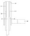
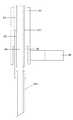
図1A及び図1Bは、本開示の一実施形態に係るインプラントの図を示す。インプラント1は、動物の頭蓋に固定されるべきベースサポート11と、ベースサポート11に貫設されている中空導管12と、中空導管12から離れてベースサポート11に配設されている第1係止部材100と、を備える。図1はさらに、軸プラグ14を備えるキャップを示す。軸プラグ14は本体を有し、中空導管12に挿入され得る。また、軸プラグ14は、中空導管12に軸プラグ14を保持するためのヘルメット15により包囲されている頭部を有する。本キャップは、例えばインプラント1が使用されていないときに、中空導管12にゴミが入るのを避けるようインプラント1に適合されていてもよい。 1A and 1B show a view of an implant according to one embodiment of the present disclosure. The
図1A及び図1Bに関して説明される実施形態においては、第1係止部材100は、円筒ピン13を含んでもよい。円筒ピン13は、ベースサポート11に略垂直であり、ベースサポート11に一体となる部分を備える。図9に示されるように、インプラント1の中空導管12にファイババンドル24が挿入されるときに、ピン13が第2係止部材26へと係止され得る。第2係止部材26は、ファイババンドル24に取り付けられたフェルールに配設されている。 In the embodiment described with respect to FIGS. 1A and 1B, the
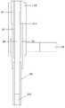
図2に関して説明される実施形態においては、第1係止部材100は、ベースサポート11に垂直であるネジ16を備えてもよい。ネジ16は、ベースサポートに配設されている第1部分161と、係止シリンダ17が同心に周設されている第2部分164と、を有する。係止シリンダ17は、本ネジの長手軸に関し並進が固定され、かつ当該軸まわりに回転自在であってもよい。第1部分161は、第1ネジ部162を備えてもよい。第1ネジ部162は、ベースサポート11に垂直な方向に本ネジの位置を調整するようベースサポート11の第2ネジ部112と協働する。本ネジが螺入されるとき、係止シリンダ17は、ネジ16の長手軸に関して移動してもよい。図8に示されるように、ネジ16及びシリンダ17を備える第1係止部材は、インプラント1の中空導管12にファイババンドル24が挿入されるときに、ファイババンドル24に配設されているフェルールの第2係止部材26に、第2係止部材26に取り付けられている係止ネジ27を使用して係止される。 In the embodiment described with respect to FIG. 2, the
この実施形態によれば、ファイババンドルがインプラントの中空導管12に挿入され、ファイババンドルに配設されたフェルールの第2係止部材が第1係止部材の係止シリンダ17に留められて、ある決定された位置にバンドルが固定されているときに、係止シリンダ17の位置を調整することによって、ファイババンドルの位置を調整することが可能であり得る。第1係止部材はさらに、係止シリンダ17の一端にてネジ16に同心に周設されているトロイド状スプリング18を備えてもよい。スプリング18は、ネジ16をネジ部112にてかつ係止シリンダ17を首部163で押し付けることにより遊びを補償することが可能である。 According to this embodiment, the fiber bundle is inserted into the
他の(図2に示していない)実施形態においては、第1係止部材は、ベースサポートに配設された第1部分を有するピンを備えてもよい。第1部分は、ピンの長手軸に関する並進を固定されかつ軸まわりに回転自在である。ピンは第2部分を有し、第2部分に係止シリンダが同心に周設されている。第2部分は、係止シリンダの第2ねじ部に協働する第1ねじ部を備える。前述のようにトロイド状スプリングが遊びの補償のために付加されてもよい。この実施形態もまた、ベースサポートに関する係止シリンダの位置調整を可能とし得る。 In other embodiments (not shown in FIG. 2), the first locking member may comprise a pin having a first portion disposed on the base support. The first part is fixed in translation with respect to the longitudinal axis of the pin and is rotatable about the axis. The pin has a second portion, and a locking cylinder is provided concentrically around the second portion. The second portion includes a first threaded portion that cooperates with the second threaded portion of the locking cylinder. As described above, a toroidal spring may be added to compensate for play. This embodiment may also allow adjustment of the position of the locking cylinder relative to the base support.
マウス頭部を定位固定フレームに保持することを要せずに、ネジ16のねじ込みによってファイババンドルプローブの位置を調整し得る。よって、ファイババンドルが係止された後でも容易に行い得る。ファイババンドルが動物の脳に挿入されているとき、脳は収縮しがちである。また、画像化する脳の決められた部位に滞在させるために、脳の再膨張によるファイババンドルの位置決めの調整も起こりうる。 The position of the fiber bundle probe can be adjusted by screwing the
第1及び第2係止部材を備える係止機構の1つの利点は、画像化する脳の決められた部位にファイババンドルを、その長手軸周りに回転させずに、かつファイババンドルが挿入される中空導管に沿って動かさずに、固定し得ることである。これは、画像取得の安定性向上につながり、自由行動動物からの画像の取得を可能とし得る。ファイババンドルが挿入される中空導管12から離れて第1係止部材が配設されているため、ファイババンドルの締め付けは、必要締め付けトルクを小さくすることによって緩和させ得る。これは、装置損傷につながりうるファイババンドルの過度の束縛を避けることを可能にし得る。 One advantage of the locking mechanism comprising the first and second locking members is that the fiber bundle is inserted into a predetermined portion of the brain to be imaged without rotating the fiber bundle about its longitudinal axis. It can be fixed without moving along the hollow conduit. This leads to an improvement in the stability of image acquisition, and may enable acquisition of images from freely moving animals. Since the first locking member is disposed away from the
動物の頭蓋に開口が掘削されると、その掘削された開口に中空導管12が現れるようにしてインプラントのベースサポート11が動物の頭蓋に固着されてもよい。ベースサポートの固着は、例えば微小ネジ及び歯科用セメントを使用して行われてもよい。 When an opening is drilled in the animal's skull, the
図10に示されるように、インプラント1は、定位固定器具3により操作されてもよい。定位固定器具3は、定位固定フレームに接続されるロッド31と、ネジ33を備える溝32と、を備える。ネジ33は溝32に配置された物体を留める。定位固定器具3は、インプラントを定位固定フレーム内で操作することを可能とするインターフェースである。定位固定フレームにおいて動物の頭部により定義される水平軸に対し水平に、インプラント1が動物の頭蓋に設置されてもよい。マウスの頭蓋は湾曲しているから、頭蓋に接触するベースサポート11の表面に、傾斜を補償するよう接着剤が塗布されてもよい。 As shown in FIG. 10, the
図1を再び参照すると、中空導管12は、ベースサポート11に垂直な筒を備えてもよい。中空導管12は、ベースサポート11の下方に延在する下部121を備えてもよい。下部121は、動物の頭蓋に掘削された開口に進入してもよい。一実施形態においては、下部121は、動物の脳に侵入するよう適合されている長さを有する。マウス頭蓋が湾曲しベースサポートが水平に据え付けられているから、脳に侵入するのに必要な長さは、ベースサポート11がマウス頭蓋の別の場所に設置されるとき、同じではなくなるかもしれない。一実施形態においては、下部121の長さは、ベースサポート11がマウス頭蓋のいかなる位置に水平に固着されるときにも脳に侵入するよう適合されている。他の一実施形態においては、下部121の長さは、ベースサポートがマウス頭蓋の少なくとも1つの位置に水平に固着されるときに脳に侵入するよう適合されている。他の一実施形態においては、下部121の長さは、ベースサポートがマウス頭蓋のいかなる位置に水平に固着されるときにも動物の脳に侵入しないよう適合されている。 Referring again to FIG. 1, the
ベースサポート11は、平行六面体形状を有してもよい。有利には、ベースサポート11は、図6Aに示されるように、台形底面直角柱形状を有してもよい。この実施形態においては、台形底面直角柱の広いほうの側面が動物の頭蓋に据えられる。この側面の下側及び台形角柱のベベル加工された縁部に接着剤が広げられ、ベースサポート11がマウス頭蓋に正確に固着される。図1Bに示されるように、ベースサポート11の台形角柱の中空導管に近接するほうの底面111は、有利には、ベースサポート11を操作する操作者が側方から中空導管12の下部121を容易に見られるように、先端部が切り取られていてもよい。それにより、操作者は、マウスの頭蓋骨に狙いを容易に定めることにより、定位固定器具3に搭載されたインプラントの下部121に定位固定フレームを正確に校正し得る。 The
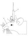
中空導管12が掘削された開口に現れるようにしてインプラント1が動物の頭蓋に位置決めされると、インプラント1の中空導管12を通じてファイババンドル24が動物の脳に挿入され得る。図12は、ファイババンドルプローブ2を受け入れたインプラント1が頭部に据え付けられているマウス4を示す。 Once the
図11に示されるように、ファイババンドルは、定位固定器具3で操作されてもよい。定位固定器具3は、インプラント1及びファイババンドルを定位固定フレーム内で操作することを可能とするインターフェースである。定位固定器具3は、ファイババンドル及びインプラントを共通の直線方向に逐次保持するよう適合されていてもよい。 As shown in FIG. 11, the fiber bundle may be operated with the stereotaxic fixture 3. The stereotaxic instrument 3 is an interface that allows the
本開示の一実施形態に係るファイババンドルプローブ2は、図4A及び図4Bに表されている。ファイババンドルプローブ2は、光を伝送するためのファイババンドル24と、ファイババンドル24の遠位部に周設されているフェルールと、を備えてもよい。ファイババンドル24の一部分がシース21で被覆されていてもよい。フェルールは、インプラント1の中空導管12へとファイババンドルを操作するための握り部25と、ファイババンドル24の遠位端がインプラント1の中空導管12を通じて動物の脳に挿入されるときに、動物の脳の決められた部位にファイババンドルを係止するよう頭蓋内インプラントの第1係止部材13と協働する第2係止部材26と、備えてもよい。動物の脳に挿入されるべきファイババンドルの遠位端は剥離されており、フェルールによって覆われていなくてもよい。図3A及び図3Bに示されるように、握り部25は、その中にファイババンドル24が取り付けられる中空管29を備えてもよい。握り部25は、ファイババンドル24の遠位部に沿って長手方向に延在していてもよい。また、第2係止部材26は、握り部25に垂直に握り部25の側方に延在していてもよい。 A
定位固定器具3は、ファイババンドルプローブの握り部25を溝32に留めることによりファイババンドル24を保持するよう適合されていてもよい。定位固定器具3は、インプラントの第1係止部材を留めることによりインプラント1を保持するよう適合されていてもよい。溝32の表面は、ファイババンドルプローブ2及びインプラント1を共通の直線方向に逐次保持するよう適合されていてもよい。溝32の表面は、U字形状の溝またはV字形状の溝(図10ないし11には図示せず)のいずれかであってもよい。 The stereotaxic fixture 3 may be adapted to hold the
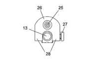
図3A及び図3Bに示されるように、フェルールの第2係止部材26は、ファイババンドル24の遠位端がインプラント1の中空導管12を通じて動物の脳に挿入され得るとき、第1係止部材13に合わさるようにアーチを形成する2つの半部28を備えてもよい。第2係止部材の一方の半部は、穴281に配設されている係止ネジ27を備えてもよい。係止ネジ27は、ファイババンドル24の遠位端がインプラント1の中空導管12を通じて動物の脳に挿入されるとき、画像化するよう決められた脳の部位で、第2係止部材の半部28間に第1係止部材13を固定することを可能とする。図6Cは、インプラントに挿入されたファイババンドルプローブの上面図であり、本開示に従う第2係止部材26の半部28に第1係止部材がどのようにして合わさり得るかを示す。 As shown in FIGS. 3A and 3B, the
図5は、本開示の一実施形態に係るファイババンドルプローブの部分断面図を模式的に示す。ファイババンドルは当初は、ファイババンドル24を包むコーティング22及びシース21を備えてもよい。ファイババンドルプローブ2を得るためには、シース21は第1遠位部分において除去されていてもよい。第1遠位部分は、シース除去区211から、動物の脳に挿入されるファイババンドル遠位端まで延在する。シース除去区211から延びる第1遠位部分は、フェルールが周設される上記遠位部に位置する。コーティング22もまた、動物の脳に挿入されるファイババンドル遠位端まで延在する第2遠位部分において除去されていてもよい。第2遠位部分は第1遠位部分よりも短い。さらに、案内シース23がファイババンドル24に配設されている。案内シース23は中空導管12の直径に適合した特定の直径を有する。案内シース23は、シース除去区211から延在し、インプラントの中空導管12に挿入されるファイババンドル24の案内部を覆ってもよい。ただし、案内シース23は、動物の脳に挿入されるべきファイババンドル遠位端は覆わないようにする。案内シース23は、ファイババンドル24に接着剤を使用して固着されていてもよい。フェルールは、案内シース23に接着剤を使用して固着されていてもよい。 FIG. 5 schematically illustrates a partial cross-sectional view of a fiber bundle probe according to an embodiment of the present disclosure. The fiber bundle may initially comprise a
図7Bは、図6Bで符号Cを付して強調した領域の拡大図であり、インプラント1に挿入されたファイババンドルプローブ2の側方の一区域を示す。図7Bは、案内シース23に被覆されインプラントの中空導管12に挿入されたファイババンドル24の案内部の側方視断面の一部分を示す。図7Bに示されるように、ファイババンドル遠位端はむき出しにされており、案内シースは、動物の脳に挿入されるファイババンドル遠位端までは延在していなくてもよい。 FIG. 7B is an enlarged view of the region highlighted with reference C in FIG. 6B and shows an area on the side of the
図7Aは、図6Bで符号Bを付して強調した領域の拡大図である。図7Aは、ファイババンドルプローブ2の側方視断面の一部分を示す。図7Aに示されるように、ファイババンドルが中に取り付けられる中空管29は、シース21に適合する内径をもつ上方部291と、案内シース23に適合する直径をもつ中間部292と、中空導管の直径に勝る直径をもつ下方部293と、を備えてもよい。こうしてファイババンドルを中空導管12に挿入することが可能となる。上方部291は、シース21で包まれたファイババンドル24の一部分を覆っており、シース除去区211まで延在してもよい。中間部292は、案内シース23に覆われたファイババンドル24の一部分を覆っていてもよい。有利には、フェルールは、中間部292の位置で接着剤を使用してファイババンドルに固着されている。下方部293は、インプラントの中空導管12に挿入されるべき案内シース23によって覆われているファイババンドルの一部分を覆っていてもよい。これにより、中空導管12に挿入されるべきファイババンドルの案内部を保護しうる。 FIG. 7A is an enlarged view of a region highlighted by adding a symbol B in FIG. 6B. FIG. 7A shows a part of a cross-sectional side view of the
画像化するよう決定された脳の部位にファイババンドルが位置決めされると、その決定された部位にファイババンドルプローブを固定するために第1及び第2部材が係止され、動物は覚醒され定位固定フレームから非拘束とされてもよい。 When the fiber bundle is positioned at the brain site determined to be imaged, the first and second members are locked to secure the fiber bundle probe to the determined site, and the animal is awakened and stereotactically fixed. The frame may be unconstrained.
図6A、図6B、図6C、図8、図9に示されるように、インプラントの第1係止部材は、ファイババンドルプローブの第2係止部材と協働する。前述のように、ピン13であるか、またはネジ16に取り付けられている係止シリンダ17である第1係止部材は、第2係止部材26の半部28により形成されるアーチに収められ、第2係止部材26の一方の半部に取り付けられた係止ネジ27によって固定されてもよい。これにより、画像取得の安定性を高めることができ、装置損傷リスクを限定しつつファイババンドルをマウスの脳から抜き出すことが許容される。よって、長期間実行される慢性実験が可能となる。 As shown in FIGS. 6A, 6B, 6C, 8, and 9, the first locking member of the implant cooperates with the second locking member of the fiber bundle probe. As described above, the first locking member, which is the
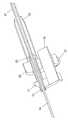
ファイババンドルプローブは、ファイババンドル24の遠位端に配設されている剛性ジャケット241をさらに備えてもよい。剛性ジャケット241は、金属材料、例えばステンレス鋼で形成されていてもよい。剛性ジャケット241は、略円筒形状を有し、ファイババンドル24を収めるよう適合されている内腔を備えてもよい。剛性ジャケット241の外径は、案内シース23の外径より小さくてもよい。剛性ジャケット241の外径は、およそ400ないし500μmであってもよい。案内シース23の遠位部において、案内シース23の内径は、剛性ジャケット241を案内シース23の内腔に収めることができるように構成されていてもよい。剛性ジャケットにより、側方及び前方の衝撃に対しファイババンドル先端を強化されるので、エンドユーザによる取り扱い及び再研磨の処理を楽にすることができる。 The fiber bundle probe may further comprise a
図13に示される一実施形態においては、剛性ジャケット241は、ファイババンドル24の遠位端の末部まで延在していてもよい。図14に示される一実施形態においては、剛性ジャケット241及びファイババンドル24の遠位端が斜めに切り取られていてもよい。図15に示される一実施形態においては、剛性ジャケット241は、ファイババンドル遠位端の末部を越えて延在し、ファイババンドル遠位端の末部に配設されている微小対物242を覆っていてもよい。微小対物242は、円柱形状を有し、ファイババンドルの直径に実質的に等しい直径を有してもよい。微小対物242は、屈折率分布型レンズであってもよく、ファイババンドル24に同軸に、例えば接着手段を使用して接続されていてもよい。代案として、微小対物242は、従来型レンズ、フィルタ、または回折素子などのその他の素子を含んでもよい。剛性ジャケット241は、ファイババンドル24と微小対物242との接続を強化し得る。 In one embodiment shown in FIG. 13, the
図16A及び図16Bは、研磨ツール5へと挿入されたファイババンドルプローブ2を示す。研磨ツール5は、研磨サポート51と、研磨サポート51に貫設されている研磨中空導管(図16A及び図16Bに図示せず)と、ファイババンドル遠位端が研磨中空導管へと挿入されるときファイババンドルプローブ2のフェルールと協働するよう研磨サポートに配設されている研磨係止部材52と、研磨ベースサポート51にファイババンドルプローブ2を係止する補助係止機構53と、を備える。研磨ベースサポート51は、ファイババンドルプローブ2が研磨サポート51に係止されるときファイババンドル遠位端が研磨面54から外に突出するよう構成されていてもよい。ファイババンドルの研磨は、剛表面の上に突出したファイババンドルの先端を磨くことにより行われてもよい。研磨サポート51の挿入面55は、研磨面54と角度を形成しており、ファイババンドル遠位端をベベルに研磨可能であってもよい。研磨導管及び研磨係止部材は、上記頭蓋内インプラントの構成を再現するよう構成されていてもよい。従って、研磨ツール5は、ファイババンドルが頭蓋内インプラントに挿入されるときの位置と同一の位置にファイババンドルを保持しうる。これにより、ファイババンドルがある決められた方向に元々ベベルである一実施形態においては、研磨ツールでのファイババンドルの再研磨により当該方向を保つことができる。 16A and 16B show the
本開示は限られた数の実施の形態について説明しているが、当業者は本開示の恩恵を受けて、本明細書に開示された本開示の範囲から逸脱することなく他の実施の形態を考案することができるということは明らかである。従って、本開示の範囲は添付の請求項によってのみ限定されるべきである。 Although the present disclosure describes a limited number of embodiments, those skilled in the art will benefit from this disclosure and will recognize other embodiments without departing from the scope of the disclosure disclosed herein. It is clear that can be devised. Accordingly, the scope of the disclosure should be limited only by the attached claims.
Claims (31)
Translated fromJapanese前記動物の頭蓋に掘削された開口の上で前記頭蓋に固着されるベースサポートと、
前記掘削された開口を通じて前記動物の脳に前記ファイババンドルを案内するよう前記ベースサポートに貫設された中空導管と、
前記ファイババンドルのフェルールと協働するよう前記ベースサポートに配設された第1係止部材であって、前記動物の脳の特定部位に前記ファイババンドルを係止するよう構成されている第1係止部材と、を備える頭蓋内インプラント。An intracranial implant for positioning a fiber bundle at a specific site in an animal brain,
A base support secured to the skull over an opening drilled in the animal's skull;
A hollow conduit extending through the base support to guide the fiber bundle through the drilled opening to the animal brain;
A first locking member disposed on the base support so as to cooperate with a ferrule of the fiber bundle, the first engagement being configured to lock the fiber bundle to a specific part of the brain of the animal. An intracranial implant comprising a stop member.
前記ベースサポートの第2ねじ部に協働する第1ねじ部を備え、前記ベースサポートに配設された第1部分であって、前記ベースサポートに実質的に垂直な方向に前記ピンの位置を調整するよう構成されている第1部分と、
同心に配設された係止シリンダを備える第2部分と、をさらに備え、前記係止シリンダは、前記ピンの長手軸に関する並進を固定されかつ前記軸まわりに回転自在である、請求項3に記載のインプラント。The pin is
A first threaded portion that cooperates with a second threaded portion of the base support, the first portion disposed on the base support, wherein the pin is positioned in a direction substantially perpendicular to the base support; A first portion configured to adjust;
A second portion comprising a concentric locking cylinder disposed concentrically, wherein the locking cylinder is fixed in translation relative to the longitudinal axis of the pin and is rotatable about the axis. The described implant.
前記ベースサポートに配設された第1部分であって、前記ピンの長手軸に関する並進を固定されかつ前記軸まわりに回転自在である第1部分と、
係止シリンダの第2ねじ部に協働する第1ねじ部を備える第2部分と、をさらに備え、前記係止シリンダは前記第2部分に同心に周設され、前記第2部分は、前記ベースサポートに実質的に垂直な方向に前記係止シリンダの位置を調整するよう構成されている、請求項3に記載のインプラント。The pin is
A first portion disposed on the base support, the first portion being fixed in translation with respect to the longitudinal axis of the pin and rotatable about the axis;
A second portion having a first threaded portion that cooperates with a second threaded portion of the locking cylinder, wherein the locking cylinder is provided concentrically around the second portion, and the second portion is The implant of claim 3, wherein the implant is configured to adjust a position of the locking cylinder in a direction substantially perpendicular to a base support.
前記頭蓋内インプラントを通じて動物の脳に挿入される遠位端を有する光伝送用のファイババンドルと、
前記光伝送用のファイババンドルの遠位部に配設されたフェルールであって、前記光伝送用のファイババンドルの遠位端が前記頭蓋内インプラントを通じて前記動物の脳に挿入されるとき前記動物の脳の特定部位に前記ファイババンドルを係止するように、前記頭蓋内インプラントの第1係止部材と協働する第2係止部材を備えるフェルールと、を備えるファイババンドルプローブ。A fiber bundle probe that is useful for brain fiber bundle microscopy in cooperation with an intracranial implant,
A fiber bundle for light transmission having a distal end inserted into the animal brain through the intracranial implant;
A ferrule disposed at a distal portion of the optical fiber bundle, wherein the distal end of the optical fiber bundle is inserted into the animal's brain through the intracranial implant. A fiber bundle probe comprising: a ferrule including a second locking member that cooperates with the first locking member of the intracranial implant so as to lock the fiber bundle to a specific part of the brain.
前記第2係止部材は、前記握り部の側方に延在しており、前記第2係止部材は、前記ファイババンドルの前記遠位端が前記インプラントの中空導管を通じて前記動物の脳に挿入されるとき、前記第1係止部材に合わさるようにアーチを形成する2つの半部を備える、請求項13に記載のファイババンドルプローブ。The ferrule comprises a grip that extends along the distal portion of the fiber bundle for manipulating the fiber bundle into the intracranial implant;
The second locking member extends to a side of the grip portion, and the second locking member is inserted into the animal brain through the distal end of the fiber bundle through the hollow conduit of the implant. 14. A fiber bundle probe according to claim 13, comprising two halves forming an arch when mated to the first locking member.
麻酔された動物の頭部を定位固定フレームに保持することと、
前記動物の頭蓋に開口を掘削することと、
インプラントのベースサポートを前記動物の頭蓋に、前記インプラントの中空導管が前記開口に現れるようにして固着することと、
前記インプラントの中空導管を通じて前記動物の脳にファイババンドルを挿入することと、
画像化する前記動物の脳の特定部位に前記ファイババンドルが位置決めされるように、前記インプラントの第1係止部材と、前記ファイババンドルに取り付けられたフェルールの第2係止部材と、を係止することと、を備える方法。A method for imaging a specific part of an animal brain,
Holding the anesthetized animal head in a stereotaxic frame;
Drilling an opening in the animal's skull;
Affixing an implant base support to the skull of the animal such that a hollow conduit of the implant appears in the opening;
Inserting a fiber bundle into the animal's brain through the hollow conduit of the implant;
The first locking member of the implant and the second locking member of the ferrule attached to the fiber bundle are locked so that the fiber bundle is positioned at a specific part of the animal brain to be imaged And a method comprising:
定位固定フレームに接続されるよう構成されているロッドと、
当該溝に配置された物体を留めるネジを備える溝と、を備え、
前記溝は、前記ファイババンドルプローブ及び前記頭蓋内インプラントを共通の直線方向に逐次保持するよう適合されている表面を備える、定位固定器具。A stereotaxic instrument for operating an intracranial implant and a fiber bundle probe,
A rod configured to be connected to a stereotaxic frame;
A groove having a screw for fastening an object disposed in the groove, and
The stereotactic instrument comprises a surface adapted to sequentially hold the fiber bundle probe and the intracranial implant in a common linear direction.
Applications Claiming Priority (3)
| Application Number | Priority Date | Filing Date | Title |
|---|---|---|---|
| US22967709P | 2009-07-29 | 2009-07-29 | |
| US61/229,677 | 2009-07-29 | ||
| PCT/IB2010/002310WO2011013011A2 (en) | 2009-07-29 | 2010-07-19 | Apparatus and method for brain fiber bundle microscopy |
Publications (2)
| Publication Number | Publication Date |
|---|---|
| JP2013500109Atrue JP2013500109A (en) | 2013-01-07 |
| JP5750440B2 JP5750440B2 (en) | 2015-07-22 |
Family
ID=43479239
Family Applications (1)
| Application Number | Title | Priority Date | Filing Date |
|---|---|---|---|
| JP2012522278AActiveJP5750440B2 (en) | 2009-07-29 | 2010-07-19 | Apparatus and method for brain fiber bundle microscopy |
Country Status (7)
| Country | Link |
|---|---|
| US (2) | US9107575B2 (en) |
| EP (1) | EP2459101B8 (en) |
| JP (1) | JP5750440B2 (en) |
| AU (1) | AU2010277231B2 (en) |
| CA (1) | CA2769607C (en) |
| ES (1) | ES2524480T3 (en) |
| WO (1) | WO2011013011A2 (en) |
Cited By (1)
| Publication number | Priority date | Publication date | Assignee | Title |
|---|---|---|---|---|
| JPWO2021230377A1 (en)* | 2020-05-15 | 2021-11-18 |
Families Citing this family (12)
| Publication number | Priority date | Publication date | Assignee | Title |
|---|---|---|---|---|
| US10292592B2 (en)* | 2014-11-13 | 2019-05-21 | The Board Of Trustees Of The Leland Stanford Junior University | Method and apparatus for optical recording of biological parameters in freely moving animals |
| WO2017070610A1 (en)* | 2015-10-21 | 2017-04-27 | Inscopix, Inc. | Implantable optical probes and systems and methods for implantation of optical probes |
| WO2017174998A1 (en) | 2016-04-06 | 2017-10-12 | The University Court Of The University Of Edinburgh | Endoscopic imaging apparatus and method |
| RU2653815C1 (en)* | 2017-03-03 | 2018-05-14 | Федеральное государственное бюджетное образовательное учреждение высшего образования "Московский государственный университет имени М.В. Ломоносова" (МГУ) | Method of implanting optic fiber probe in animal brain to generate controlled feedback |
| RU176725U1 (en)* | 2017-03-20 | 2018-01-25 | Федеральное государственное бюджетное образовательное учреждение высшего образования "Московский государственный университет имени М.В. Ломоносова" (МГУ) | DETECTABLE FIBER OPTICAL PROBE WITH MULTICHANNEL FIBERS |
| GB201707239D0 (en) | 2017-05-05 | 2017-06-21 | Univ Edinburgh | Optical system and method |
| US11944270B1 (en)* | 2017-11-17 | 2024-04-02 | PhotonEdge Inc. | Systems and methods of rotation compensation for brain optical imaging and stimulation |
| US12053147B2 (en) | 2017-12-18 | 2024-08-06 | Arizona Board Of Regents On Behalf Of The University Of Arizona | Multi-field miniaturized micro-endoscope |
| KR102270248B1 (en) | 2019-10-29 | 2021-06-25 | (주)서한케어 | Apparatus For Medicine Infusion |
| CN112842604B (en)* | 2019-11-27 | 2022-12-06 | 香港理工大学深圳研究院 | A kind of optogenetics experimental method and system |
| US12350010B2 (en)* | 2019-12-05 | 2025-07-08 | Regents Of The University Of Minnesota | Systems and methods for multimodal neural sensing |
| CN120167892A (en)* | 2023-12-20 | 2025-06-20 | 中国科学院深圳先进技术研究院 | An animal experimental model and method for calcium signal recording |
Citations (8)
| Publication number | Priority date | Publication date | Assignee | Title |
|---|---|---|---|---|
| JPH02280742A (en)* | 1989-04-22 | 1990-11-16 | Taisuke Otsuki | Constant position-brain operation device using laser endoscope |
| JPH10503105A (en)* | 1994-07-22 | 1998-03-24 | ユニバーシティ オブ ワシントン | Stereotactic implantation method |
| JPH11137568A (en)* | 1997-11-10 | 1999-05-25 | Shigeru Munemoto | Full bearing expedient type stereotactic surgery apparatus |
| JP2001161625A (en)* | 1999-12-13 | 2001-06-19 | Olympus Optical Co Ltd | Rigid scope |
| JP2001327474A (en)* | 2000-05-23 | 2001-11-27 | Tomy Ltd | Brain electrode fixator |
| JP2002502276A (en)* | 1997-05-15 | 2002-01-22 | リージェンツ オブ ザ ユニバーシティ オブ ミネソタ | Trajectory guide for surgical instruments |
| US20080306375A1 (en)* | 2007-06-07 | 2008-12-11 | Surgi-Vision, Inc. | Mri-guided medical interventional systems and methods |
| JP2010528763A (en)* | 2007-06-07 | 2010-08-26 | サージヴィジョン,インコーポレイテッド | MRI guided medical intervention system and method |
Family Cites Families (14)
| Publication number | Priority date | Publication date | Assignee | Title |
|---|---|---|---|---|
| US3465803A (en)* | 1967-07-26 | 1969-09-09 | Penn Eng & Mfg Corp | Captive screw device and a method for securing together the parts thereof |
| US5338139A (en)* | 1993-10-20 | 1994-08-16 | Penn Engineering & Manufacturing Corp. | Shrouded captive screw |
| US5579774A (en) | 1994-03-07 | 1996-12-03 | Camino Neurocare, Inc. | Method and apparatus for monitoring local cerebral physiology |
| WO1997042870A1 (en)* | 1996-05-14 | 1997-11-20 | Camino Neurocare, Inc. | Expandable parenchymal bolt |
| JP2001231759A (en)* | 2000-02-24 | 2001-08-28 | Tomy Ltd | Brain electrode fixation device |
| WO2001078814A1 (en)* | 2000-04-13 | 2001-10-25 | U Hoi S | Stereotaxic detachable needle extension |
| US6567690B2 (en) | 2000-10-16 | 2003-05-20 | Cole Giller | Method and apparatus for probe localization in brain matter |
| US7695723B2 (en)* | 2002-12-31 | 2010-04-13 | Sygnis Bioscience Gmbh & Co. Kg | Methods of treating neurological conditions with hematopoietic growth factors |
| EP1773219A2 (en) | 2004-06-24 | 2007-04-18 | BCU International | Method and medical device for rapid and accurate entry through soft tissue and bone |
| US8788021B1 (en)* | 2005-01-24 | 2014-07-22 | The Board Of Trustees Of The Leland Stanford Junior Univerity | Live being optical analysis system and approach |
| US8430888B2 (en) | 2005-02-22 | 2013-04-30 | Boston Scientific Neuromodulation Corporation | Minimally invasive methods for locating an optimal location for deep brain stimulation |
| US20070270647A1 (en)* | 2006-05-19 | 2007-11-22 | Ams Research Corporation | Handle for Multifunction Endoscope |
| US20090048610A1 (en)* | 2007-08-14 | 2009-02-19 | Bme Capital Holdings Ltd. | Medical probe introducer |
| US8747418B2 (en)* | 2008-08-15 | 2014-06-10 | Monteris Medical Corporation | Trajectory guide |
- 2010
- 2010-07-19USUS13/386,468patent/US9107575B2/enactiveActive
- 2010-07-19EPEP10768547.1Apatent/EP2459101B8/enactiveActive
- 2010-07-19AUAU2010277231Apatent/AU2010277231B2/enactiveActive
- 2010-07-19WOPCT/IB2010/002310patent/WO2011013011A2/enactiveApplication Filing
- 2010-07-19ESES10768547.1Tpatent/ES2524480T3/enactiveActive
- 2010-07-19JPJP2012522278Apatent/JP5750440B2/enactiveActive
- 2010-07-19CACA2769607Apatent/CA2769607C/enactiveActive
- 2015
- 2015-06-05USUS14/731,949patent/US9730586B2/enactiveActive - Reinstated
Patent Citations (8)
| Publication number | Priority date | Publication date | Assignee | Title |
|---|---|---|---|---|
| JPH02280742A (en)* | 1989-04-22 | 1990-11-16 | Taisuke Otsuki | Constant position-brain operation device using laser endoscope |
| JPH10503105A (en)* | 1994-07-22 | 1998-03-24 | ユニバーシティ オブ ワシントン | Stereotactic implantation method |
| JP2002502276A (en)* | 1997-05-15 | 2002-01-22 | リージェンツ オブ ザ ユニバーシティ オブ ミネソタ | Trajectory guide for surgical instruments |
| JPH11137568A (en)* | 1997-11-10 | 1999-05-25 | Shigeru Munemoto | Full bearing expedient type stereotactic surgery apparatus |
| JP2001161625A (en)* | 1999-12-13 | 2001-06-19 | Olympus Optical Co Ltd | Rigid scope |
| JP2001327474A (en)* | 2000-05-23 | 2001-11-27 | Tomy Ltd | Brain electrode fixator |
| US20080306375A1 (en)* | 2007-06-07 | 2008-12-11 | Surgi-Vision, Inc. | Mri-guided medical interventional systems and methods |
| JP2010528763A (en)* | 2007-06-07 | 2010-08-26 | サージヴィジョン,インコーポレイテッド | MRI guided medical intervention system and method |
Cited By (3)
| Publication number | Priority date | Publication date | Assignee | Title |
|---|---|---|---|---|
| JPWO2021230377A1 (en)* | 2020-05-15 | 2021-11-18 | ||
| WO2021230377A1 (en)* | 2020-05-15 | 2021-11-18 | 京セラ株式会社 | Biomedical tube and biometric device |
| JP7489072B2 (en) | 2020-05-15 | 2024-05-23 | 京セラ株式会社 | Biometric tube and biometric device |
Also Published As
| Publication number | Publication date |
|---|---|
| EP2459101B1 (en) | 2014-08-20 |
| AU2010277231B2 (en) | 2015-01-22 |
| CA2769607C (en) | 2017-12-05 |
| US9107575B2 (en) | 2015-08-18 |
| US9730586B2 (en) | 2017-08-15 |
| WO2011013011A2 (en) | 2011-02-03 |
| ES2524480T3 (en) | 2014-12-09 |
| US20120123236A1 (en) | 2012-05-17 |
| US20150265153A1 (en) | 2015-09-24 |
| EP2459101B8 (en) | 2014-11-19 |
| JP5750440B2 (en) | 2015-07-22 |
| EP2459101A2 (en) | 2012-06-06 |
| AU2010277231A2 (en) | 2012-03-22 |
| WO2011013011A3 (en) | 2011-06-23 |
| CA2769607A1 (en) | 2011-02-03 |
| AU2010277231A1 (en) | 2012-03-08 |
Similar Documents
| Publication | Publication Date | Title |
|---|---|---|
| JP5750440B2 (en) | Apparatus and method for brain fiber bundle microscopy | |
| US4624243A (en) | Endoscope having a reusable eyepiece and a disposable distal section | |
| KR101930110B1 (en) | Laser video endoscope | |
| CN105263398A (en) | Surgical imaging systems | |
| US8035902B2 (en) | Optical unit for probe and optical unit producing method | |
| CN105658164A (en) | Microwave ablation catheter, handle, and system | |
| JP2004510536A (en) | Surgical instruments | |
| US20150073270A1 (en) | Imaging method and apparatus | |
| JP7566061B2 (en) | Miniature lens-to-fiber connector with automatic focusing function | |
| US20150366437A1 (en) | Image relaying cannula with detachable self-aligning connector | |
| US20200129049A1 (en) | Sterile sheath for confocal endomicroscopy scanner probe | |
| RU2653815C1 (en) | Method of implanting optic fiber probe in animal brain to generate controlled feedback | |
| JPH11155798A (en) | Hard endoscope | |
| US20100309547A1 (en) | Objective-optical-system positioning apparatus and examination apparatus | |
| JP6459103B1 (en) | Guide mechanism for examination scope | |
| KR101698574B1 (en) | Catheter for endoscope | |
| JP2013085653A (en) | Endoscope system | |
| CN112603561A (en) | Miniature multi-photon microscopic imaging device and using method | |
| CN112741588B (en) | Fusion device | |
| JP4043991B2 (en) | Microscope observation apparatus and probe type microscope | |
| CN217611027U (en) | Protective sleeve, implanted lens and living body brain imaging device | |
| CN219270856U (en) | Operation handle for confocal probe and confocal microscopic imaging device | |
| JP2010227170A (en) | Optical instrument movement mechanism | |
| WO2024108518A1 (en) | Method and system for synchronous fluorescence imaging of deep brain region and whole cerebral cortex scale | |
| JPH0210499Y2 (en) |
Legal Events
| Date | Code | Title | Description |
|---|---|---|---|
| A621 | Written request for application examination | Free format text:JAPANESE INTERMEDIATE CODE: A621 Effective date:20130424 | |
| A977 | Report on retrieval | Free format text:JAPANESE INTERMEDIATE CODE: A971007 Effective date:20140120 | |
| A131 | Notification of reasons for refusal | Free format text:JAPANESE INTERMEDIATE CODE: A131 Effective date:20140218 | |
| A601 | Written request for extension of time | Free format text:JAPANESE INTERMEDIATE CODE: A601 Effective date:20140519 | |
| A602 | Written permission of extension of time | Free format text:JAPANESE INTERMEDIATE CODE: A602 Effective date:20140526 | |
| A521 | Request for written amendment filed | Free format text:JAPANESE INTERMEDIATE CODE: A523 Effective date:20140715 | |
| A131 | Notification of reasons for refusal | Free format text:JAPANESE INTERMEDIATE CODE: A131 Effective date:20141125 | |
| A521 | Request for written amendment filed | Free format text:JAPANESE INTERMEDIATE CODE: A523 Effective date:20150218 | |
| TRDD | Decision of grant or rejection written | ||
| A01 | Written decision to grant a patent or to grant a registration (utility model) | Free format text:JAPANESE INTERMEDIATE CODE: A01 Effective date:20150428 | |
| A61 | First payment of annual fees (during grant procedure) | Free format text:JAPANESE INTERMEDIATE CODE: A61 Effective date:20150518 | |
| R150 | Certificate of patent or registration of utility model | Ref document number:5750440 Country of ref document:JP Free format text:JAPANESE INTERMEDIATE CODE: R150 | |
| R250 | Receipt of annual fees | Free format text:JAPANESE INTERMEDIATE CODE: R250 | |
| R250 | Receipt of annual fees | Free format text:JAPANESE INTERMEDIATE CODE: R250 | |
| R250 | Receipt of annual fees | Free format text:JAPANESE INTERMEDIATE CODE: R250 | |
| R250 | Receipt of annual fees | Free format text:JAPANESE INTERMEDIATE CODE: R250 | |
| R250 | Receipt of annual fees | Free format text:JAPANESE INTERMEDIATE CODE: R250 | |
| S111 | Request for change of ownership or part of ownership | Free format text:JAPANESE INTERMEDIATE CODE: R313113 | |
| R350 | Written notification of registration of transfer | Free format text:JAPANESE INTERMEDIATE CODE: R350 | |
| R250 | Receipt of annual fees | Free format text:JAPANESE INTERMEDIATE CODE: R250 | |
| R250 | Receipt of annual fees | Free format text:JAPANESE INTERMEDIATE CODE: R250 | |
| R250 | Receipt of annual fees | Free format text:JAPANESE INTERMEDIATE CODE: R250 |