JP2013257229A - System for detecting rotation angle of rotating body - Google Patents
System for detecting rotation angle of rotating bodyDownload PDFInfo
- Publication number
- JP2013257229A JP2013257229AJP2012133923AJP2012133923AJP2013257229AJP 2013257229 AJP2013257229 AJP 2013257229AJP 2012133923 AJP2012133923 AJP 2012133923AJP 2012133923 AJP2012133923 AJP 2012133923AJP 2013257229 AJP2013257229 AJP 2013257229A
- Authority
- JP
- Japan
- Prior art keywords
- section
- error
- waveform
- rotation angle
- resolver
- Prior art date
- Legal status (The legal status is an assumption and is not a legal conclusion. Google has not performed a legal analysis and makes no representation as to the accuracy of the status listed.)
- Pending
Links
Images


Landscapes
- Transmission And Conversion Of Sensor Element Output (AREA)
Abstract
Translated fromJapaneseDescription
Translated fromJapanese本発明は、レゾルバを用いて回転体の回転角を検出するシステムに関する。 The present invention relates to a system for detecting a rotation angle of a rotating body using a resolver.
従来、レゾルバを用いて回転体の回転角を検出する技術が知られている。レゾルバから得られる検出値は、検出回路内の素子のバラツキおよびレゾルバのロータとステータ間の軸心のずれ等に起因する誤差を含んでおり、より高精度な回転角を得るためにレゾルバが検出した回転角を補正する手法が提案されている。 Conventionally, a technique for detecting the rotation angle of a rotating body using a resolver is known. The detection value obtained from the resolver includes errors due to variations in the elements in the detection circuit and the shaft center misalignment between the resolver rotor and stator. The resolver detects this in order to obtain a more accurate rotation angle. A method for correcting the rotation angle is proposed.
例えば、特開2011−252789号(以下、特許文献1という)には、レゾルバを用いて回転角を算出する装置の制御装置は、取得部31、算出部32、学習部33、算出部34を含み、取得部はレゾルバが実際に出力するレゾルバ信号θを取得し、算出部は理想角と実際のレゾルバ信号との差をレゾルバ誤差値として算出し、学習部は今回周期よりも1周期前からN(Nは2以上の整数)周期前までのN個のレゾルバ誤差値の波形に対してそれらの間の散らばりを平均化するための「なまし処理」を施してレゾルバ誤差学習値の波形を算出し、算出部は今回周期のレゾルバ信号と、レゾルバ誤差値と、学習部が学習したレゾルバ誤差学習値とに基づいて、補正後のレゾルバ信号を算出することが記載されている。 For example, in Japanese Patent Application Laid-Open No. 2011-252789 (hereinafter referred to as Patent Document 1), a control device for a device that calculates a rotation angle using a resolver includes an acquisition unit 31, a calculation unit 32, a learning unit 33, and a calculation unit 34. The acquisition unit acquires the resolver signal θ actually output by the resolver, the calculation unit calculates the difference between the ideal angle and the actual resolver signal as a resolver error value, and the learning unit starts from one cycle before the current cycle. N resolver error value waveforms up to N (N is an integer greater than or equal to 2) cycles are subjected to “smoothing processing” to average the dispersion between them, and the resolver error learning value waveform is obtained. It is described that the calculation unit calculates the corrected resolver signal based on the resolver signal of the current cycle, the resolver error value, and the resolver error learned value learned by the learning unit.
また、特開2011−107022号公報(以下、特許文献2という)には、レゾルバ装置において、一周期中の回転角データのうち少なくとも2つである特定角の各々について、現在より3回転前周期で特定角が得られてから前々回周期で特定角が得られるまでの所要時間T2に対する現在より2回前周期で特定角が得られてから前回周期で特定角が得られるまでの所要時間T1の時間変化率が判定閾値以下のときには、前回周期でレゾルバが略等速で回転していたと判定して前回周期で得られた回転角データと理想角データとの差分を用いて現在周期での回転角データを補正することが記載されている。 Japanese Patent Laid-Open No. 2011-107022 (hereinafter referred to as “Patent Document 2”) discloses that a resolver device has a period of three rotations before the current for each of specific angles that are at least two of rotation angle data in one period. The required time T1 from when the specific angle is obtained in the previous cycle to the specific time T2 until the specific angle is obtained in the previous cycle after the specific angle is obtained twice in the previous period from the present time T2 until the specific angle is obtained in the cycle two times before the specific angle is obtained. When the time change rate is less than or equal to the judgment threshold, it is determined that the resolver was rotating at a substantially constant speed in the previous cycle, and the rotation in the current cycle is performed using the difference between the rotation angle data obtained in the previous cycle and the ideal angle data. The correction of corner data is described.
さらに、特開2010−96708号公報(以下、特許文献3という)には、ステータと軸倍角n(nは自然数)のロータとを有するレゾルバがモータの回転子の回転角を機械角のn倍の角度で検出する角度検出装置において、区間番号演算部は、検出角度が回転子の1回転期間を等間隔に分割したn個の区間のうち、いずれの区間に属するかを判定して、区間毎に検出角度を補正することが記載されている。 Further, Japanese Patent Laid-Open No. 2010-96708 (hereinafter referred to as Patent Document 3) discloses that a resolver having a stator and a rotor having a shaft angle multiplier n (n is a natural number) sets the rotation angle of the rotor of the motor to n times the mechanical angle. In the angle detection device that detects the angle, the section number calculation unit determines which section of the n sections in which the detected angle is divided into one rotation period of the rotor at equal intervals, It is described that the detection angle is corrected every time.
上記特許文献1ないし3に記載されるレゾルバを用いた回転角の検出では、レゾルバが比較的近くに配置されているモータからの漏洩磁束等の影響によってレゾルバ信号に含まれる誤差波形が過渡的に変化することがある。そうした過渡的な誤差波形の変化に応じてレゾルバ信号の誤差補正を適切に行わないと、回転角の検出精度が悪くなる可能性がある。 In the detection of the rotation angle using the resolver described in Patent Documents 1 to 3, the error waveform included in the resolver signal is transiently caused by the influence of leakage magnetic flux from a motor that is disposed relatively close to the resolver. May change. If the error correction of the resolver signal is not appropriately performed according to such a transient change in the error waveform, the detection accuracy of the rotation angle may be deteriorated.
本発明の目的は、モータからの漏洩磁束などの変化による影響も考慮して補正用誤差を選択し、検出精度を向上させることである。 An object of the present invention is to select a correction error in consideration of the influence of changes such as leakage magnetic flux from a motor and improve detection accuracy.
本発明に係る回転体の回転角検出システムは、レゾルバと、前記レゾルバから得られた回転角の波形の誤差補正を行う制御部とを備え、前記レゾルバは、軸倍角N(Nは自然数)のロータを有し、前記制御部は、前記ロータの各回転周期を分割したN個の区間のうち、補正対象とする区間より前の回転周期に属し、かつ前記補正対象とする区間と各回転周期における回転角度の範囲が同じである基準区間における誤差波形と、前記基準区間よりも後の区間における誤差波形とにそれぞれ所定の重みをつけて平均した波形を補正用誤差として用いて誤差補正を行う、回転体の回転角検出システムであって、前記制御部は、前記補正対象とする区間の直前区間における誤差波形と、前記直前区間より前の回転周期に属しかつ前記直前区間と各回転周期における回転角度の範囲が同じ区間である第1区間における誤差波形との第1偏差が、前記直前区間における誤差波形と、前記第1区間よりも後の区間でありかつ前記直前区間と各回転周期における回転角度の範囲が異なる区間における誤差波形との第2偏差よりも大きいとき、前記それぞれ所定の重みに比べて、前記基準区間における誤差波形につける重みを小さくするとともに、前記基準区間よりも後の区間における誤差波形につける重みを大きくした補正用誤差を用いて誤差補正を行うものである。 A rotational angle detection system for a rotating body according to the present invention includes a resolver and a control unit that corrects an error in a rotational angle waveform obtained from the resolver, and the resolver has an axial multiplication angle N (N is a natural number). The controller has a rotor, and the control unit belongs to a rotation period before a section to be corrected among N sections obtained by dividing each rotation period of the rotor, and the section to be corrected and each rotation period The error waveform in the reference section having the same rotation angle range and the error waveform in the section after the reference section are averaged with predetermined weights, and the error correction is performed. The rotation angle detection system for a rotating body, wherein the control unit includes an error waveform in a section immediately before the section to be corrected, a rotation period before the immediately preceding section, and each section and each rotation. The first deviation from the error waveform in the first section that is the same range of the rotation angle in the period is the error waveform in the immediately preceding section, the section after the first section, and each section and each rotation. When the range of the rotation angle in the cycle is larger than the second deviation from the error waveform in a different section, the weight attached to the error waveform in the reference section is made smaller than the respective predetermined weights, and more than in the reference section Error correction is performed using a correction error with a larger weight attached to an error waveform in a later section.
本発明に係る回転体の回転角検出システムにおいて、前記第1偏差および前記第2偏差は、前記誤差波形の絶対値の最大値の差、または、前記誤差波形の積分値の差であってもよい。 In the rotation angle detection system for a rotating body according to the present invention, the first deviation and the second deviation may be a difference in maximum value of the absolute value of the error waveform or a difference in integral value of the error waveform. Good.
また、本発明に係る回転体の回転角検出システムにおいて、前記基準区間よりも後の区間は前記直前区間であり、前記第1区間よりも後の区間でありかつ前記直前区間と各回転周期における回転角度の範囲が異なる区間は、前記直前区間の直前の区間であってもよい。 Further, in the rotation angle detection system for a rotating body according to the present invention, the section after the reference section is the immediately preceding section, is the section after the first section, and is in the preceding section and each rotation cycle. The section having a different rotation angle range may be a section immediately before the immediately preceding section.
さらに、本発明に係る回転体の回転角検出システムは、前記第1偏差が前記第2偏差よりも大きいことが所定回数続いたとき、前記それぞれの所定の重みに比べて、前記基準区間における誤差波形につける重みを小さくするとともに、前記基準区間よりも後の区間における誤差波形につける重みを大きくした補正用誤差を用いて誤差補正を行ってもよい。 Further, the rotation angle detection system for a rotating body according to the present invention provides an error in the reference section that is larger than the respective predetermined weights when the first deviation is greater than the second deviation for a predetermined number of times. Error correction may be performed using a correction error in which the weight attached to the waveform is reduced and the weight attached to the error waveform in the section after the reference section is increased.
本発明に係る回転体の回転角検出システムによれば、モータからの漏洩磁束などの変化による影響も考慮して補正用誤差を選択することにより回転角の検出精度を向上させることができる。 According to the rotation angle detection system for a rotating body according to the present invention, it is possible to improve the detection accuracy of the rotation angle by selecting the correction error in consideration of the influence of changes such as leakage magnetic flux from the motor.
以下に、本発明に係る実施の形態(以下、実施形態という)について添付図面を参照しながら詳細に説明する。この説明において、具体的な形状、材料、数値、方向等は、本発明の理解を容易にするための例示であって、用途、目的、仕様等にあわせて適宜変更することができる。また、以下において複数の実施形態や変形例などが含まれる場合、それらの特徴部分を適宜に組み合わせて用いることは当初から想定されている。 DESCRIPTION OF EMBODIMENTS Hereinafter, embodiments according to the present invention (hereinafter referred to as embodiments) will be described in detail with reference to the accompanying drawings. In this description, specific shapes, materials, numerical values, directions, and the like are examples for facilitating the understanding of the present invention, and can be appropriately changed according to the application, purpose, specification, and the like. In addition, when a plurality of embodiments and modifications are included in the following, it is assumed from the beginning that these characteristic portions are used in appropriate combinations.
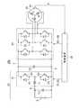
図1は、本発明の一実施形態である回転体の回転角検出システムが適用されるモータ駆動制御システム100の全体構成図である。図1に示すように、モータ駆動制御システム100は、直流電圧発生部10と、平滑コンデンサC0と、インバータ14と、モータ20と、制御装置(制御部)30とを備える。 FIG. 1 is an overall configuration diagram of a motor
モータ20は、例えば、電動車両(ハイブリッド自動車、電気自動車や燃料電池車等の電気エネルギによって車両駆動力を発生する自動車をいうものとする)の駆動輪を駆動するためのトルクを発生するための走行用電動機である。あるいは、このモータ20は、エンジンにて駆動される発電機の機能を持つように構成されてもよく、電動機および発電機の機能を併せ持つように構成されてもよい。さらに、モータ20は、エンジンに対して電動機として動作し、例えば、エンジン始動を行ない得るようなものとしてハイブリッド自動車に組み込まれるようにしてもよい。すなわち、本実施の形態において、モータ20は、交流駆動の電動機、発電機、および電動発電機(モータジェネレータ)を含むものである。 For example, the
直流電圧発生部10は、直流電源Bと、平滑コンデンサC1と、コンバータ12とを含む。直流電源Bは、代表的には、ニッケル水素またはリチウムイオン等の二次電池や電気二重層キャパシタ等の蓄電装置により構成される。また、平滑コンデンサC1は、直流電源Bに出入りする直流電流を平滑化する機能を有する。 DC
コンバータ12は、リアクトルL1と、電力用半導体スイッチング素子Q1,Q2と、ダイオードD1,D2とを含む。電力用半導体スイッチング素子Q1およびQ2は、正極線7および負極線5の間に直列に接続される。電力用半導体スイッチング素子Q1およびQ2のオン・オフは、制御装置30からのスイッチング制御信号S1およびS2によって制御される。
この実施形態において、電力用半導体スイッチング素子(以下、単に「スイッチング素子」と称する)としては、IGBT(Insulated Gate Bipolar Transistor)、電力用MOS(Metal Oxide Semiconductor)トランジスタあるいは、電力用バイポーラトランジスタ等を用いることができる。スイッチング素子Q1,Q2に対しては、ダイオードD1,D2が配置されている。リアクトルL1は、スイッチング素子Q1およびQ2の接続ノードと直流電源Bの正極に接続された電力線6との間に接続される。また、平滑コンデンサC0は、正極線7および負極線5の間に接続され、コンバータ12およびインバータ14間で授受される直流電流を平滑化する機能を有する。 In this embodiment, an IGBT (Insulated Gate Bipolar Transistor), a power MOS (Metal Oxide Semiconductor) transistor, a power bipolar transistor, or the like is used as a power semiconductor switching element (hereinafter simply referred to as “switching element”). be able to. Diodes D1, D2 are arranged for switching elements Q1, Q2. Reactor L1 is connected between a connection node of switching elements Q1 and Q2 and power line 6 connected to the positive electrode of DC power supply B. Smoothing capacitor C0 is connected between positive electrode line 7 and
インバータ14は、正極線7および負極線5の間に並列に設けられる三相(U、V、W相)の各相の上下アーム(スイッチング素子)から成る。各相の上下アームのオン/オフは、制御装置30からのスイッチング制御信号S3〜S8によって制御される。 The
モータ20は、代表的には、3相の永久磁石型同期電動機であり、U,V,W相の3つのコイルの一端が中性点に共通接続されて構成される。さらに、各相コイルの他端は、インバータ14の各相の上下アームの中間点と接続されている。 The
コンバータ12は、基本的には、各スイッチング周期内でスイッチング素子Q1およびQ2が相補的かつ交互にオン/オフするように制御される。コンバータ12は、昇圧動作時には、直流電源Bが出力する直流電圧Vbを直流電圧VH(インバータ14への入力電圧に相当するこの直流電圧を、以下「システム電圧」とも称する)へ昇圧する。この昇圧動作は、スイッチング素子Q2のオン期間にリアクトルL1に蓄積された電磁エネルギを、スイッチング素子Q1およびダイオードD1を介して、正極線7へ供給することにより行なわれる。
また、コンバータ12は、降圧動作時には、直流電圧VHを直流電圧Vbに降圧する。この降圧動作は、スイッチング素子Q1のオン期間にリアクトルL1に蓄積された電磁エネルギを、スイッチング素子Q2およびダイオードD2を介して、電力線6へ供給することにより行なわれる。これらの昇圧動作または降圧動作における電圧変換比(VHおよびVbの比)は、上記スイッチング周期に対するスイッチング素子Q1,Q2のオン期間比(デューティ比)により制御される。 Further, converter 12 steps down DC voltage VH to DC voltage Vb during the step-down operation. This step-down operation is performed by supplying the electromagnetic energy accumulated in the reactor L1 during the ON period of the switching element Q1 to the power line 6 via the switching element Q2 and the diode D2. The voltage conversion ratio (ratio of VH and Vb) in these step-up or step-down operations is controlled by the on-period ratio (duty ratio) of the switching elements Q1 and Q2 with respect to the switching period.
制御装置30は、図示しないCPU(Central Processing Unit)およびメモリを内蔵した電子制御ユニット(ECU:Electronic Control Unit)により構成され、当該メモリに記憶されたマップおよびプログラムに基づいて、モータ駆動制御システム100の動作を制御する。なお、制御装置30は、本実施形態におけるモータ20のロータ(回転体に相当する、図示せず)の回転角を検出する装置の一部を構成している。 The
モータ20には、レゾルバ40が設けられている。レゾルバ40もまた回転角を検出する装置の一部を構成する。レゾルバ40は、後述するレゾルバロータの回転角、すなわちモータ20の回転角を示すレゾルバ信号θを制御装置30へ出力する。 A
次に、図2を参照してレゾルバ40について説明する。図2(a)はレゾルバの構成を概略的に示す図であり、図2(b)は上から順にモータシャフトの回転角、レゾルバの検出角、各区間の検出誤差を示すグラフである。 Next, the
レゾルバ40は、図2(a)に示すように、モータ20の回転軸22に固定されるロータ42と、ロータ42に対向配置されるステータ44とを備える。本実施形態におけるレゾルバ40のロータ42は、周方向に等間隔で形成された3つの突極部43a,43b,43cを外周部に備え、各突極部43a,43b,43c間をつなぐ周方向部分1〜3(図中では○で囲んだ番号として表示)がそれぞれ略円弧状の曲面を成している。したがって、本実施形態では、レゾルバ40の軸倍角N(Nは自然数)が3である場合を例示する。 As shown in FIG. 2A, the
一方、本実施形態のレゾルバ40のステータ44は、ロータ42に対向する内周部にM個の検出コイル46を周方向に等間隔で備える。各検出コイル46は、渡り導線48を介してそれぞれ直列接続されており、2つの出力端子49a,49bから出力信号を取り出せる周知の構成を有する。ここで、本実施形態では、検出コイル46の個数Mが、上記ロータ42の極数Nに対して非整数倍に設定されている。本実施形態では、ステータ44に8つの検出コイル46が設けられた例が示されている。 On the other hand, the
なお、本実施形態ではロータ極数Nと検出コイルの数Mとが非整数倍の関係にあるレゾルバを例示するが、これらの数N,Mは整数倍となるよう構成されてもよい。また、上記では1相出力タイプのレゾルバを例示するが、互いに位相が90度ずれた2つの検出信号が出力される2相出力タイプのレゾルバが用いられてもよい。 In the present embodiment, a resolver in which the number of rotor poles N and the number of detection coils M are in a non-integer multiple relationship is illustrated, but these numbers N and M may be configured to be an integral multiple. In the above, a one-phase output type resolver is illustrated, but a two-phase output type resolver that outputs two detection signals whose phases are shifted by 90 degrees may be used.
レゾルバ40がN倍角の場合、レゾルバ40は、モータ20が1回転する間(すなわちレゾルバ40のロータが1回転する間)に、位相が360度変化するレゾルバ信号θをN回繰り返し出力する。言い換えれば、モータ20が1/N回転する間にレゾルバ信号θの位相は360度変化する。図2(b)の上段と中段にその様子が示されている。以下の説明で用いる「レゾルバ周期」又は「区間」とは、レゾルバ信号θの電気位相が360度変化する周期を意味するものとする。 When the
図2(b)の下段には、レゾルバ信号θに含まれる検出誤差Δθを示している。検出誤差Δθは、図示されるように、ロータ42の機械1周期をN分割した区間1〜Nにおいてそれぞれ一致しない場合がある。これは、ロータ42の寸法公差、レゾルバ40のステータ44がロータ42と同心状に組み付けられていないこと、ロータ42の極数Nと検出コイル46の数Mとが非整数倍の関係にあること等に起因して生じるものである。 The lower part of FIG. 2B shows a detection error Δθ included in the resolver signal θ. As shown in the drawing, the detection error Δθ may not match in each of sections 1 to N obtained by dividing one cycle of the
また、レゾルバ40から出力される信号には、上記レゾルバ信号θの他に、1回転信号が含まれる。この1回転信号とは、ロータ42が機械1回転周期ごとに生成されるパルス信号であり、ロータ42に付されているノースマークを検出したタイミングで出力される。以下、この1回転周期信号を基準周期信号という。この基準周期信号は、後述するレゾルバ誤差の影響を受けることがない。 The signal output from the
さらに、レゾルバ40から出力されるレゾルバ信号θに基づき算出される検出角が、3倍角の場合には360度、720度、1080度に到達するごとに区間信号が生成される。この区間信号は、レゾルバ周期信号に相当するものであり、本実施形態の3倍角のレゾルバ40では3回に1回の区間信号が上記基準周期信号に一致する。 Further, when the detection angle calculated based on the resolver signal θ output from the
具体的には、図2(a)を参照すると、ステータ44の内周において原点位置Xが予め規定されており、この原点位置Xを各突極部43a,43b,43cが通過するごとに区間信号が生成されることになり、以下においては突極部43a,43b間の円弧状部分が原点位置Xを通過しているときを区間1、突極部43b,43c間の円弧状部分が原点位置Xを通過しているときを区間2、突極部43c,43a間の円弧状部分が原点位置Xを通過しているときを区間3という。 Specifically, referring to FIG. 2A, an origin position X is defined in advance on the inner periphery of the
一般に、レゾルバ40が出力するレゾルバ信号θには、ロータ42の実回転角に対して、ロータ42の回転に同期した誤差成分(以下、「レゾルバ誤差」という)が含まれることが知られている。このレゾルバ誤差の影響を排除するためには、レゾルバ誤差を検出し、レゾルバ誤差をレゾルバ信号θから除く補正(以下、「キャンセル補正」ともいう)を行なうことが望ましい。 Generally, it is known that the resolver signal θ output from the
上記のような誤差補正は、レゾルバ信号θから算出される検出角から、一定の回転速度(角速度)でロータ42が機械1周期だけ回転するとした場合における理想角を減じて算出することができる。そして、このような誤差補正は、図2(b)を参照して上述したように、区間1〜Nごとに異なることがあるので、各区間ごとに検出角から各区間の理想角を減じて誤差補正を行うことが検出精度をより高めるうえで好ましい。 The error correction as described above can be calculated by subtracting the ideal angle when the
しかし、レゾルバ40が比較的近くに配置されているモータ20からの漏洩磁束等の影響を受けることによってレゾルバ信号θに含まれる誤差波形が過渡的に変化することがある。例えば、モータ20の回転速度またはトルクが急増したときにモータ20からの漏洩磁束が一時的に大きくなり、その影響によってレゾルバ信号θに含まれる誤差が過渡的に大きく変化した場合や、レゾルバ40の温度変化による影響によってレゾルバ信号θに含まれる誤差が過渡的に変化した場合等が想定される。そうした過渡時には1周期前の対応する区間(すなわち区間番号が同じ区間)で学習した誤差波形を用いて今回補正対象となる区間について補正を行うと、レゾルバ40を用いた回転角の検出精度が悪くなる可能性がある。そこで、このような過渡時における誤差補正の精度を向上させるための本実施形態の回転角を検出する装置では、下記に述べるような構成を採用している。 However, the error waveform included in the resolver signal θ may change transiently due to the influence of leakage magnetic flux or the like from the
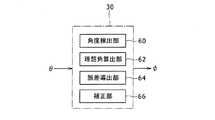
図3は制御装置30の機能ブロック図である。図4は、前回周期と今回周期における各区間のレゾルバ信号とレゾルバ誤差値とを示す図である。図5は、制御装置30の誤差導出部において実行される処理手順を示すフローチャートである。 FIG. 3 is a functional block diagram of the
図3に示すように、制御装置30は、角度検出部60、理想角算出部62、誤差導出部64、および、補正部66を含む。これらの各部は、好ましくはソフトウェア処理によって実現されるが、一部がハードウェア動作によって実現されてもよい。 As shown in FIG. 3, the
角度検出部60は、レゾルバ信号θからロータ42の回転角を検出する機能を有する。ここで検出される回転角には、上述したような寸法公差による誤差、組付誤差、軸倍角Nの非整数倍の誤差等が含まれる。 The
理想角算出部62は、各区間の理想角θiを算出する機能を有する。具体的には、各区間の区切りを示す区間信号の立上がりエッジ間の時間、すなわち電気1周期の時間Tを計測し、この時間Tで電気角360度を一定勾配で割り当てて理想角θiとする。このように算出される理想角θiは、図4中に傾斜した破線で示すように、各区間1〜3においてそれぞれ一定勾配を有する直線状に描くことができる。 The ideal
誤差導出部64は、検出角θから上記理想角θiを減算して、各区間1〜3ごとに対応するレゾルバ誤差Δθを算出する機能を有する。ここで算出されたレゾルバ誤差Δθは、制御装置30に設けられるRAM等の記憶部に記憶されて随時に更新されるが、少なくとも2回転周期分の各区間1〜3のレゾルバ誤差Δθ1〜Δθ3が保持されるように構成される。 The
補正部66は、検出角θに対して上記レゾルバ誤差Δθ1〜Δθ3を用いて各区間1〜3ごとにキャンセルする補正を行って補正後検出角φを出力する機能を有する。ここで出力される補正後検出角φが上述したようにモータ20の駆動制御に用いられる。ただし、後述するように、通常時と判定される場合には誤差導出部64から出力される通常時誤差を補正用誤差として用いて検出角θを補正し、他方、過渡時と判定される場合には誤差導出部64から出力される過渡時誤差を補正用誤差として用いて検出角θを補正する。 The
続いて、誤差導出部64における処理について、図4,5を参照して詳細に説明する。ここでは、図4に示すように、レゾルバ20のロータ42の現在の回転位置が今回周期における区間2にあって、この区間2が今回の補正対象となる区間(以下、「今回区間」という)である場合を例として以下で説明する。また、図5に示される処理は、誤差導出部64において所定時間ごとに繰り返し実行される。 Subsequently, processing in the
まず、誤差導出部64は、ステップS10において、1周期前区間間誤差である第1偏差ΔErr1を算出する。この第1偏差ΔErr1は、今回区間2と同じ今回周期の直前の区間1で学習した誤差波形Err_1pの絶対値の最大値と、当該区間1の直前の区間3よりさらに前の区間であって前回周期の対応する区間1で学習した誤差波形Err_1p_oldの絶対値の最大値との差分または偏差として求められる。 First, in step S10, the
次に、誤差導出部64は、ステップS12において、直前区間間誤差である第2偏差ΔErr2を算出する。この第2偏差Err2は、今回区間2と同じ今回周期の直前の区間1で学習した誤差波形Err_1pの絶対値の最大値と、当該区間1の直前の区間3、すなわち前回周期の最後の区間3で学習した誤差波形Err_3pの絶対値の最大値との差分または偏差として求められる。 Next, in step S12, the
なお、上記においては第1偏差および第2偏差は、各区間の誤差波形の絶対値の最大値の差分として求められると説明したが、これに限定されるものではなく、各区間における誤差積分値の差分として求められてもよい。 In the above description, it has been described that the first deviation and the second deviation are obtained as a difference between the maximum values of the absolute values of the error waveforms in each section. However, the present invention is not limited to this, and the error integrated value in each section. May be obtained as a difference between the two.
次に、誤差導出部64は、ステップS14において、第1偏差ΔErr1と第2偏差ΔErr2とを比較する。そして、第1偏差ΔErr1が第2偏差ΔErr2よりも大きいとき(ステップS14でYES)、過渡時であると判定して、後述するステップS16に進む。他方、第1偏差ΔErr1が第2偏差ΔErr2以下であるとき(ステップS14でNO)、通常時であると判定して、後述するステップ18進む。 Next, the
ここで、第1偏差ΔErr1が第2偏差ΔErr2以下であるとき、言い換えれば、第2偏差ΔErr2が第1偏差ΔErr1よりも大きいときに通常時と判定するのは、ロータ42が略等速で回転するレゾルバ40から出力されるレゾルバ信号θにおいて前回周期および今回周期の対応する区間1同士の誤差波形は略同様であることが常態であると想定されるためである。これを逆にいうと、第1偏差ΔErr1が第2偏差ΔErr2より大きいときには、モータ20からの漏洩磁束等の影響によってレゾルバ信号θに含まれる誤差が変化している過渡時であると判定することができる。 Here, when the first deviation ΔErr1 is equal to or smaller than the second deviation ΔErr2, in other words, when the second deviation ΔErr2 is larger than the first deviation ΔErr1, it is determined that the normal time is that the
ステップS14において通常時であると判定されたとき、誤差導出部64は、続くステップS18で、今回区間より前の回転周期に属し、かつ今回区間と回転角度の範囲が同じである基準区間における誤差波形と、基準区間よりも後の区間における誤差波形とにそれぞれ所定の重みをつけて平均した波形を通常誤差Δθnormalとして出力する。より詳しくは、機械1周期前である前回周期において今回区間2と対応する区間2(基準区間に相当)で学習した誤差波形Err_2pと、該区間2よりも後に区間である、今回区間の直前の区間1の誤差波形Err_1pとに、例えばそれぞれ90%および10%という重みをつけて加重平均した波形を通常誤差Δθnormalを出力する。これにより、制御装置30の補正部66は、前回周期の対応区間の誤差波形ΔErr_2pが主として反映された通常誤差Δθnormalを用いて今回区間2のレゾルバ信号θを補正する。 When it is determined in step S14 that the current time is normal, the
これに対し、ステップS14で過渡時であると判定されたとき、誤差導出部64は、続くステップS16で、上記それぞれ所定の重みに比べて、前回周期の対応する区間2における誤差波形につける重みを小さくするとともに、該区間2よりも後の区間における誤差波形につける重みを大きくした補正用誤差を過渡時誤差Δθtransitとして出力する。より詳しくは、前回周期の対応する区間2の誤差波形Err_2pにつける重みを例えば10%と小さくするとともに、今回区間2により近い区間である例えば直前の区間1で学習した誤差波形ΔErr_1pにつける重みを例えば90%と大きくして、それらを加重平均して算出される過渡時誤差Δθtransitを出力する。これにより、制御装置30の補正部66は、直前区間1の誤差波形ΔErr_1pが主として反映された過渡時誤差Δθtransitを用いて今回区間2のレゾルバ信号θを補正する。 On the other hand, when it is determined in step S14 that the current state is a transition time, the
上述したように、本実施形態の回転角を検出する装置によれば、レゾルバ信号θに過渡時の乱れがあって誤差波形が変化していると判定されるとき、今回補正区間に時間的に近い区間で学習した誤差波形を主として用いて今回区間の補正を行うことで、過渡時においても回転角の検出を精度良く行なうことができる。このように、モータ20の漏洩磁束などの変化による影響も考慮して補正用誤差として過渡時誤差または通常誤差を選択することによりモータロータの回転角の検出精度を向上させることができる。 As described above, according to the apparatus for detecting the rotation angle of the present embodiment, when it is determined that the resolver signal θ is disturbed at the time of transition and the error waveform is changed, the current correction interval is temporally changed. By correcting the current section mainly using the error waveform learned in the near section, the rotation angle can be detected with high accuracy even during the transition. In this way, the accuracy of detection of the rotation angle of the motor rotor can be improved by selecting the transient error or the normal error as the correction error in consideration of the influence of the change of the leakage magnetic flux of the
また、本実施形態では、レゾルバ信号θだけに基づいて過渡時かどうかの判定を行うことから、モータの回転数やトルク指令や駆動電流等の他の情報を考慮して過渡時の判定を行う場合に比べて、処理負担を軽減できるともに処理時間も短縮できる。したがって、レゾルバ信号θの補正を適時に且つ迅速に行ううえで有利である。 Further, in this embodiment, since it is determined whether or not it is a transient state based only on the resolver signal θ, the transient state determination is performed in consideration of other information such as the motor speed, torque command, and drive current. Compared to the case, the processing load can be reduced and the processing time can be shortened. Therefore, it is advantageous to correct the resolver signal θ in a timely and prompt manner.
また、本実施形態では過度時であるか否かの判定において補正対象となる今回区間の直前の区間の誤差波形を考慮することで、過渡時の判定を適時に精度よく行うことができる。 Further, in the present embodiment, in determining whether the time is excessive, the error waveform of the section immediately before the current section to be corrected is taken into consideration, so that the determination at the time of transition can be accurately performed in a timely manner.
また、上記第2偏差ΔErr2を今回補正区間の直前の区間の誤差波形とそれに隣接する更に直前の区間の誤差波形との偏差とすることで、過渡時の判断を適宜に精度よく行うことができる。 Further, by determining the second deviation ΔErr2 as the deviation between the error waveform of the section immediately before the current correction section and the error waveform of the immediately preceding section adjacent thereto, the determination at the time of transition can be performed appropriately and accurately. .
また、上記第1偏差ΔErr1を今回補正区間の直前の区間の誤差波形とそれに対応する前回周期の対応区間の誤差波形との偏差とすることで、過渡時の判断を精度よく行うことができる。 Further, by determining the first deviation ΔErr1 as the deviation between the error waveform of the section immediately before the current correction section and the corresponding error waveform of the corresponding section of the previous cycle, it is possible to make a judgment at the time of transition with high accuracy.
さらに、過渡時誤差Δθtransitを今回補正区間の直前の区間の誤差波形の重みを大きくして導出することで、過渡時の誤差補正を精度よく行うことができる。加えて、通常誤差Δθnormalを今回補正区間に対応する前回周期の対応区間に学習した誤差波形の重みを大きくして導出することで、通常時の誤差補正も精度良く行うことができる。 Further, the error correction at the time of transition can be accurately performed by deriving the error at the time of transition Δθtransit by increasing the weight of the error waveform in the section immediately before the current correction section. In addition, by deriving the normal error Δθnormal by increasing the weight of the error waveform learned in the corresponding period of the previous period corresponding to the current correction period, the normal error correction can be performed with high accuracy.
なお、本発明に係る回転角を検出する装置は、上記実施形態の構成に限定されるものではなく、本願の特許請求の範囲に記載された事項の範囲で種々の変更または改良が可能である。 The device for detecting the rotation angle according to the present invention is not limited to the configuration of the above embodiment, and various modifications or improvements can be made within the scope of the matters described in the claims of the present application. .
上記においては、第2偏差ΔErr2を今回補正区間の直前の区間の誤差波形と、この直前区間に隣接する更に直前の区間の誤差波形とに基づいて算出したが、これに限定されるものではなく、今回補正区間の直前の区間の誤差波形と、この直前区間より前であって2つ以上の過去区間の誤差波形とに基づいて第2偏差を算出してもよい。 In the above, the second deviation ΔErr2 is calculated based on the error waveform of the section immediately before the current correction section and the error waveform of the section immediately preceding the immediately preceding section. However, the present invention is not limited to this. The second deviation may be calculated based on the error waveform of the section immediately before the current correction section and the error waveforms of two or more past sections before the previous section.
また、上記においては、第1偏差ΔErr1を今回区間の直前の区間の誤差波形と、この直前区間に対応する前回周期の対応区間の誤差波形とに基づいて算出したが、これに限定されるものではなく、例えば、今回区間の直前の区間の誤差波形と、この直前区間に対応する前回周期および前々回周期の2つの対応区間の誤差波形の平均値等とに基づいて第1偏差を算出してもよい。 In the above description, the first deviation ΔErr1 is calculated based on the error waveform of the section immediately before the current section and the error waveform of the corresponding section of the previous cycle corresponding to the immediately preceding section. However, the present invention is not limited to this. Instead, for example, the first deviation is calculated based on the error waveform of the section immediately before the current section and the average value of the error waveforms of the two corresponding sections of the previous period and the previous cycle corresponding to the immediately preceding section. Also good.
さらに、上記においては、第1偏差が第2偏差よりも大きいときに過渡時であると判定したが、これに限定されるものではない。例えば、第1偏差が第2偏差よりも大きいことが所定回数続いたときに過渡時であると判定してもよい。ここで所定回数は、2回以上とすることができる。このようにすれば、突発的なノイズ等がレゾルバ信号に乗っても、それを過渡時と判定しないようにすることができ、過渡時の判定精度が向上する利点がある。 Further, in the above description, the transition is determined when the first deviation is larger than the second deviation. However, the present invention is not limited to this. For example, when the first deviation is larger than the second deviation for a predetermined number of times, it may be determined that the transition is in progress. Here, the predetermined number of times can be two or more. In this way, even if sudden noise or the like gets on the resolver signal, it can be determined not to be in transition, and there is an advantage that the determination accuracy in transition is improved.
5 負極線、6 電力線、7 正極線、10 直流電圧発生部、12 コンバータ、14 インバータ、20 モータ、22 回転軸、30 制御装置、40 レゾルバ、42 ロータ、43a,43b,43c 突極部、44 ステータ、46 検出コイル、48 渡り導線、49a,49b 出力端子、51 基準Z信号、52a,52b,53a,53b Z信号、60 角度検出部、62 理想角算出部、64 誤差導出部、66 補正部、100 モータ駆動制御システム、B 直流電源、C0,C1 平滑コンデンサ、D1,D2 ダイオード、Err1 第1偏差、Err2 第2偏差、L1 リアクトル、N ロータ極数、M 検出コイル数、Q1,Q2 電力用半導体スイッチング素子、S1−S8 スイッチング制御信号、θ レゾルバ信号またはレゾルバ角度、θi 理想角、Δθnormal 通常誤差、Δθtransit 過渡時誤差。 5 Negative electrode wire, 6 Power line, 7 Positive wire, 10 DC voltage generator, 12 Converter, 14 Inverter, 20 Motor, 22 Rotating shaft, 30 Control device, 40 Resolver, 42 Rotor, 43a, 43b, 43c Salient pole, 44 Stator, 46 detection coil, 48 crossover conductor, 49a, 49b output terminal, 51 reference Z signal, 52a, 52b, 53a, 53b Z signal, 60 angle detection unit, 62 ideal angle calculation unit, 64 error derivation unit, 66 correction unit , 100 Motor drive control system, B DC power supply, C0, C1 smoothing capacitor, D1, D2 diode, Err1 first deviation, Err2 second deviation, L1 reactor, N number of rotor poles, M number of detection coils, Q1, Q2 For power Semiconductor switching element, S1-S8 switching control signal, θ resolver signal or Is the resolver angle, θi ideal angle, Δθnormal normal error, Δθtransit transient error.
Claims (4)
Translated fromJapanese前記レゾルバは、軸倍角N(Nは自然数)のロータを有し、
前記制御部は、前記ロータの各回転周期を分割したN個の区間のうち、補正対象とする区間より前の回転周期に属し、かつ前記補正対象とする区間と各回転周期における回転角度の範囲が同じである基準区間における誤差波形と、前記基準区間よりも後の区間における誤差波形とにそれぞれ所定の重みをつけて平均した波形を補正用誤差として用いて誤差補正を行う、回転体の回転角検出システムであって、
前記制御部は、
前記補正対象とする区間の直前区間における誤差波形と、前記直前区間より前の回転周期に属しかつ前記直前区間と各回転周期における回転角度の範囲が同じ区間である第1区間における誤差波形との第1偏差が、
前記直前区間における誤差波形と、前記第1区間よりも後の区間でありかつ前記直前区間と各回転周期における回転角度の範囲が異なる区間における誤差波形との第2偏差よりも大きいとき、
前記それぞれ所定の重みに比べて、前記基準区間における誤差波形につける重みを小さくするとともに、前記基準区間よりも後の区間における誤差波形につける重みを大きくした補正用誤差を用いて誤差補正を行う、
回転体の回転角検出システム。A resolver, and a controller that performs error correction of the waveform of the rotation angle obtained from the resolver,
The resolver has a rotor with a shaft angle multiplier N (N is a natural number),
The control unit belongs to the rotation period before the section to be corrected among the N sections obtained by dividing each rotation period of the rotor, and the range of the rotation angle in each rotation period and the section to be corrected The rotation of the rotating body performs error correction using a waveform obtained by averaging the error waveform in the reference section with the same weight and the error waveform in the section after the reference section with a predetermined weight as a correction error. An angle detection system,
The controller is
The error waveform in the immediately preceding section of the section to be corrected and the error waveform in the first section that belongs to the rotation period before the immediately preceding section and has the same rotation angle range in each rotation period as the immediately preceding section. The first deviation is
When the error waveform in the immediately preceding section is greater than the second deviation between the error waveform in the section that is a section after the first section and the rotation angle range in each rotation period is different from the immediately preceding section,
The error correction is performed using a correction error in which the weight attached to the error waveform in the reference section is made smaller and the weight attached to the error waveform in the section after the reference section is made larger than the respective predetermined weights. ,
Rotation angle detection system for rotating bodies.
前記第1偏差および前記第2偏差は、前記誤差波形の絶対値の最大値の差、または、前記誤差波形の積分値の差である、回転体の回転角検出システム。
The rotation angle detection system for a rotating body according to claim 1,
The rotation angle detection system for a rotating body, wherein the first deviation and the second deviation are a difference between maximum values of absolute values of the error waveform or a difference between integral values of the error waveform.
前記基準区間よりも後の区間は前記直前区間であり、前記第1区間よりも後の区間でありかつ前記直前区間と各回転周期における回転角度の範囲が異なる区間は、前記直前区間の直前の区間である、回転体の回転角検出システム。The rotation angle detection system for a rotating body according to claim 1,
The section after the reference section is the immediately preceding section, the section after the first section, and the section in which the rotation angle range in each rotation period is different from the immediately preceding section is the section immediately before the immediately preceding section. A rotation angle detection system for a rotating body that is a section.
前記第1偏差が前記第2偏差よりも大きいことが所定回数続いたとき、前記それぞれの所定の重みに比べて、前記基準区間における誤差波形につける重みを小さくするとともに、前記基準区間よりも後の区間における誤差波形につける重みを大きくした補正用誤差を用いて誤差補正を行う、回転体の回転角検出システム。The rotation angle detection system for a rotating body according to claim 1,
When the first deviation continues to be greater than the second deviation a predetermined number of times, the weight attached to the error waveform in the reference interval is made smaller than the respective predetermined weights, and after the reference interval. A rotation angle detection system for a rotating body that performs error correction using a correction error with a larger weight attached to an error waveform in the section.
Priority Applications (1)
| Application Number | Priority Date | Filing Date | Title |
|---|---|---|---|
| JP2012133923AJP2013257229A (en) | 2012-06-13 | 2012-06-13 | System for detecting rotation angle of rotating body |
Applications Claiming Priority (1)
| Application Number | Priority Date | Filing Date | Title |
|---|---|---|---|
| JP2012133923AJP2013257229A (en) | 2012-06-13 | 2012-06-13 | System for detecting rotation angle of rotating body |
Publications (1)
| Publication Number | Publication Date |
|---|---|
| JP2013257229Atrue JP2013257229A (en) | 2013-12-26 |
Family
ID=49953781
Family Applications (1)
| Application Number | Title | Priority Date | Filing Date |
|---|---|---|---|
| JP2012133923APendingJP2013257229A (en) | 2012-06-13 | 2012-06-13 | System for detecting rotation angle of rotating body |
Country Status (1)
| Country | Link |
|---|---|
| JP (1) | JP2013257229A (en) |
Cited By (2)
| Publication number | Priority date | Publication date | Assignee | Title |
|---|---|---|---|---|
| JPWO2019142875A1 (en)* | 2018-01-19 | 2020-05-28 | 日本精工株式会社 | Electric power steering device and method for detecting rotation angle of motor for electric power steering device |
| CN111207778A (en)* | 2018-11-22 | 2020-05-29 | Tdk株式会社 | Angle sensor and angle sensor system |
- 2012
- 2012-06-13JPJP2012133923Apatent/JP2013257229A/enactivePending
Cited By (3)
| Publication number | Priority date | Publication date | Assignee | Title |
|---|---|---|---|---|
| JPWO2019142875A1 (en)* | 2018-01-19 | 2020-05-28 | 日本精工株式会社 | Electric power steering device and method for detecting rotation angle of motor for electric power steering device |
| CN111207778A (en)* | 2018-11-22 | 2020-05-29 | Tdk株式会社 | Angle sensor and angle sensor system |
| CN111207778B (en)* | 2018-11-22 | 2022-01-14 | Tdk株式会社 | Angle sensor and angle sensor system |
Similar Documents
| Publication | Publication Date | Title |
|---|---|---|
| JP5333583B2 (en) | Rotation angle calculation device and rotation angle calculation method | |
| US8339076B2 (en) | Electric motor drive control apparatus | |
| US8836255B2 (en) | Control device | |
| JP5696700B2 (en) | Rotor position estimation device, motor control system, and rotor position estimation method | |
| US20160233800A1 (en) | Integrated circuit | |
| US9419554B2 (en) | Control device of AC motor | |
| JP5549553B2 (en) | Rotating machine control device | |
| JP5605312B2 (en) | Rotating machine control device | |
| JP2013257229A (en) | System for detecting rotation angle of rotating body | |
| JP2013234914A (en) | Rotation angle detection system | |
| JP2017022909A (en) | Current sensor abnormality diagnosis apparatus | |
| JP5923955B2 (en) | Control device for multi-phase rotating machine | |
| JP2011252789A (en) | Device and method for calculating rotation angle | |
| JP2013072686A (en) | Vehicle | |
| JP2019037019A (en) | Device and method for controlling rotary electric machine | |
| JP5729333B2 (en) | Device for detecting rotation angle | |
| US11848633B2 (en) | Controller for AC rotary electric machine | |
| JP6292062B2 (en) | Full-section concentrated winding switched reluctance motor controller | |
| JP7058777B1 (en) | Control device for permanent magnet type rotary electric machine | |
| JP6659189B1 (en) | AC rotating machine control device, vehicle AC rotating machine device, and electric power steering device | |
| JP6659188B1 (en) | AC rotating machine control device, vehicle AC rotating machine device, and electric power steering device | |
| JP2017118689A (en) | AC motor control system | |
| JP2015162928A (en) | Ac motor controlling device | |
| JP2015171311A (en) | Controller of ac motor |