JP2013252260A - Endoscope apparatus - Google Patents
Endoscope apparatusDownload PDFInfo
- Publication number
- JP2013252260A JP2013252260AJP2012129185AJP2012129185AJP2013252260AJP 2013252260 AJP2013252260 AJP 2013252260AJP 2012129185 AJP2012129185 AJP 2012129185AJP 2012129185 AJP2012129185 AJP 2012129185AJP 2013252260 AJP2013252260 AJP 2013252260A
- Authority
- JP
- Japan
- Prior art keywords
- unit
- imaging
- image
- endoscope
- distal end
- Prior art date
- Legal status (The legal status is an assumption and is not a legal conclusion. Google has not performed a legal analysis and makes no representation as to the accuracy of the status listed.)
- Granted
Links
- 238000005452bendingMethods0.000claimsabstractdescription71
- 230000007246mechanismEffects0.000claimsabstractdescription60
- 238000003384imaging methodMethods0.000claimsabstractdescription56
- 238000003780insertionMethods0.000claimsdescription123
- 230000037431insertionEffects0.000claimsdescription123
- 230000001133accelerationEffects0.000claimsdescription12
- 238000001514detection methodMethods0.000claimsdescription10
- 238000006073displacement reactionMethods0.000claimsdescription7
- 230000015572biosynthetic processEffects0.000claimsdescription2
- 238000003786synthesis reactionMethods0.000claimsdescription2
- 230000002194synthesizing effectEffects0.000abstractdescription2
- 238000012545processingMethods0.000description48
- 238000000034methodMethods0.000description34
- 230000008569processEffects0.000description28
- 238000005286illuminationMethods0.000description9
- 230000004048modificationEffects0.000description7
- 238000012986modificationMethods0.000description7
- 238000005516engineering processMethods0.000description4
- 230000006870functionEffects0.000description4
- 238000007689inspectionMethods0.000description3
- CURLTUGMZLYLDI-UHFFFAOYSA-NCarbon dioxideChemical compoundO=C=OCURLTUGMZLYLDI-UHFFFAOYSA-N0.000description2
- 238000012937correctionMethods0.000description2
- 230000000875corresponding effectEffects0.000description2
- 238000010586diagramMethods0.000description2
- 230000009467reductionEffects0.000description2
- 229910002092carbon dioxideInorganic materials0.000description1
- 239000001569carbon dioxideSubstances0.000description1
- 230000006835compressionEffects0.000description1
- 238000007906compressionMethods0.000description1
- 230000001276controlling effectEffects0.000description1
- 230000002596correlated effectEffects0.000description1
- 238000005260corrosionMethods0.000description1
- 230000007797corrosionEffects0.000description1
- 230000003247decreasing effectEffects0.000description1
- 239000000428dustSubstances0.000description1
- 230000000694effectsEffects0.000description1
- 238000001839endoscopyMethods0.000description1
- 238000012615high-resolution techniqueMethods0.000description1
- 230000003287optical effectEffects0.000description1
- 230000011514reflexEffects0.000description1
- 238000005070samplingMethods0.000description1
Images


Landscapes
- Instruments For Viewing The Inside Of Hollow Bodies (AREA)
- Endoscopes (AREA)
Abstract
Description
Translated fromJapanese本発明は、内視鏡装置に関し、特に、複数の静止画を合成して高画質な内視鏡画像を生成可能な内視鏡装置に関する。 The present invention relates to an endoscope apparatus, and more particularly to an endoscope apparatus that can generate a high-quality endoscope image by combining a plurality of still images.
従来より、内視鏡装置は、医療用分野及び工業用分野で広く用いられている。内視鏡装置は、観察対象物内に挿入する細長い挿入部を有し、例えば挿入部の先端部には撮像素子が設けられている。内視鏡装置は、工業分野においては、その細長の挿入部を配管、ボイラ、タービン、エンジン等の内部に挿入して、内部の傷や腐食を観察、検査するために使用される。 Conventionally, endoscope apparatuses have been widely used in the medical field and the industrial field. The endoscope apparatus has an elongated insertion portion that is inserted into an observation object, and an imaging element is provided at a distal end portion of the insertion portion, for example. In an industrial field, an endoscope apparatus is used for inserting and inserting an elongated insertion portion into a pipe, a boiler, a turbine, an engine or the like to observe and inspect internal scratches and corrosion.
一方、コンパクトカメラ、一眼レフカメラ等のデジタルカメラでは、撮像素子から得られた撮像信号に対する各種画像処理技術が実用化されている。そのような種々の画像処理技術の中には、複数枚の静止画からランダムノイズを検出して低減するノイズ低減技術や、かつ複数枚の静止画を合成して高画質な1枚の静止画を生成する高解像度化技術がある。 On the other hand, in a digital camera such as a compact camera or a single-lens reflex camera, various image processing techniques for an image pickup signal obtained from an image pickup device have been put into practical use. Among such various image processing technologies, there are noise reduction technology for detecting and reducing random noise from a plurality of still images, and one high-quality still image by combining a plurality of still images. There is a high resolution technology that generates
例えば、特開平11−75099号公報及び特開2006−140885号公報に開示のように、撮像素子自体の画素数を増加させなくても撮像画像の高画質化を行うことができる技術がある。これらの公報に開示された技術は、撮像素子へ入射する光の位置をずらす機構を撮影装置内に設けたり、撮影装置を保持している撮影者の手の動きを利用して複数フレームの撮影を行うものである。撮像素子へ入射する光の位置をずらして複数枚の画像を得ることによって、ランダムノイズやAGCのゲインが高くなると発生する固定パターンノイズを除去し、さらに、画像中の輪郭部の高周波信号を得て、ノイズが少なくかつ高解像度な画像を得ることができる。 For example, as disclosed in Japanese Patent Application Laid-Open No. 11-75099 and Japanese Patent Application Laid-Open No. 2006-140885, there is a technique that can improve the image quality of a captured image without increasing the number of pixels of the image sensor itself. In the techniques disclosed in these publications, a mechanism for shifting the position of light incident on the image sensor is provided in the photographing apparatus, or a plurality of frames are photographed by using the movement of the photographer's hand holding the photographing apparatus. Is to do. By shifting the position of the light incident on the image sensor and obtaining multiple images, the fixed pattern noise that occurs when the gain of the random noise and AGC increases is removed, and the high-frequency signal of the contour in the image is obtained. Thus, a high-resolution image with less noise can be obtained.
しかし、このような撮像素子へ入射する光の位置をずらして複数枚の画像を得ることによってノイズが少なくかつ高解像度な画像を得る技術を、内視鏡装置に適用する場合、観察窓は細長の挿入部の先端部に設けられているため、上述したような撮像素子へ入射する入射光の位置をずらす機構を細長の挿入部の先端部に設けることはできない。 However, when applying a technique for obtaining a high-resolution image with less noise by shifting the position of light incident on the image sensor to obtain a plurality of images, the observation window is elongated. Therefore, a mechanism for shifting the position of the incident light incident on the image sensor as described above cannot be provided at the distal end of the elongated insertion portion.
また、工業用内視鏡装置の場合、挿入部は検査対象である機械装置内で、例えば配管内で、撮像時に静止しているため、上述したような撮影者の手の動きを利用することはできない。
そのため、工業用内視鏡装置に、撮像素子へ入射する光の位置をずらして複数枚の画像を得ることによってノイズが少なくかつ高画質な画像を得る技術を適用することはできなかった。Further, in the case of an industrial endoscope apparatus, the insertion portion is stationary at the time of imaging in a mechanical apparatus to be inspected, for example, in a pipe, so use the movement of the photographer's hand as described above. I can't.
For this reason, it has not been possible to apply to an industrial endoscope apparatus a technique for obtaining a high-quality image with less noise by shifting the position of light incident on an image sensor to obtain a plurality of images.
そこで、本発明は、撮像素子へ入射する光の位置をずらして複数枚の画像を得ることによってノイズが少なくかつ高画質な画像を得ることができる内視鏡装置を提供することを目的とする。 Accordingly, an object of the present invention is to provide an endoscope apparatus that can obtain a high-quality image with less noise by obtaining a plurality of images by shifting the position of light incident on an image sensor. .
本発明の一態様による内視鏡装置は、被検体を撮像する撮像部と、内視鏡挿入部の挿入を補助する駆動部を有する挿入補助部と、前記挿入補助部の駆動部を駆動させて前記挿入部の先端部を動かして、前記撮像部により前記被検体を異なる位置から撮像して複数の静止画を得るように制御する制御部と、前記撮像部により撮像して得られた前記被検体の前記複数の静止画を合成する画像合成部と、を有する。 An endoscope apparatus according to an aspect of the present invention drives an imaging auxiliary unit having an imaging unit that images a subject, an insertion auxiliary unit that assists insertion of the endoscope insertion unit, and a driving unit of the insertion auxiliary unit. A control unit that moves the distal end of the insertion unit, images the subject from different positions by the imaging unit, and controls to obtain a plurality of still images; and the image obtained by imaging by the imaging unit An image synthesis unit that synthesizes the plurality of still images of the subject.
本発明によれば、撮像素子へ入射する光の位置をずらして複数枚の画像を得ることによってノイズが少なくかつ高画質な画像を得ることができる内視鏡装置を提供することができる。 According to the present invention, it is possible to provide an endoscope apparatus that can obtain a high-quality image with less noise by obtaining a plurality of images by shifting the position of light incident on an image sensor.
以下、図面を参照して本発明の実施の形態を説明する。
(第1の実施の形態)
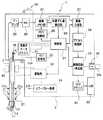
図1は、本実施の形態に係わる内視鏡装置の構成を示す構成図である。
内視鏡装置1は、細長い内視鏡挿入部(以下、単に挿入部という)2と本体部3とを有して構成される電子内視鏡装置である。挿入部2の基端部は、本体部3に接続されており、挿入部2の先端部には、撮像部11と、撮像部11の近傍に設けられた加速度センサ12と、挿入部2の先端部近傍の湾曲部に設けられた電動湾曲機構13と、が設けられている。撮像部11は、被検体を撮像するためのCCDなどの撮像素子であり、照明部からの照明光が照射された被写体からの反射光を先端部の観察窓を通して撮像して、撮像信号を出力する。挿入部2の先端部に設けられた加速度センサ12は、3軸加速度センサであり、挿入部2の先端部の動きを検出する。電動湾曲機構13は、挿入部2に設けられた湾曲部を湾曲させる湾曲機構である。Embodiments of the present invention will be described below with reference to the drawings.
(First embodiment)
FIG. 1 is a configuration diagram showing a configuration of an endoscope apparatus according to the present embodiment.
The
また、内視鏡装置1は、図示しない操作部を有しており、ユーザは、操作部に設けられた各種スイッチなどを操作することによって、内視鏡装置1の各種機能を選択して実行指示することができる。 Further, the
本体部3は、内視鏡装置1の制御を行う制御部21と、プリアンプ22と、アナログフロントエンド部(以下、AFEと略す)23と、画像メモリ部24と、メモリ制御部25と、位置ずれ量検出部26と、画像合成部27と、プロセス処理部28と、画像記録/再生部29と、カードスロット部30と、LCDドライバ31と、LCD32と、LED照明部33と、湾曲モータドライバ34と、湾曲用モータ35と、撮像指示ボタン36とを含んで構成されている。なお、湾曲用モータ35は、挿入部2の上下左右の4方向への湾曲のために4つ設けられているが、図1では1つのみ示している。
制御部21は、図示しない中央処理装置(CPU)と記憶装置を含む。その記憶装置は、ROM及びRAMを含み、ROMには、各種機能及び各種モードに応じた制御プログラム及びそのプログラムの実行に必要な各種データが記憶されており、CPUがユーザからの指示に応じたプログラムを読み出して実行する。制御部21は、各種制御プログラムに従って、内視鏡装置1の各部を制御する。また、制御部21は、撮像部11を駆動する駆動回路も内蔵している。The
The
プリアンプ22は、撮像部11からの撮像信号を増幅する。AFE23は、プリアンプ22からの撮像信号に対して、相関二重サンプリング等の各種処理を行う。画像メモリ部24は、AFE23からの撮像信号を一時記憶する記憶部である。画像メモリ部24は、メモリ制御部25により制御されて、複数の静止画の撮像信号を記憶することができる。メモリ制御部25は、制御部21により制御される。
位置ずれ量検出部26は、画像メモリ部24に記憶された複数の静止画の画像データ間の位置ずれ量を検出する回路である。その位置ずれ量は、制御部21に出力される。The
The positional deviation
画像合成部27は、制御部21の制御の下で、複数の画像データ間の位置ずれ量に基づいて複数の画像を合成する処理を行う回路である。具体的には、画像合成部27は、画像メモリ部24に一時記憶された複数の静止画の画像データを位置合わせしながら重畳して一枚の高画質な画像を作成する。この画像合成部27における複数枚処理により、効果的なノイズリダクションや、いわゆる超解像技術による高解像度化が可能になる。すなわち、画像合成部27は、撮像部11により撮像して得られた被検体の複数の静止画を合成する画像合成部を構成する。 The
なお、画像合成部27は、ライブ画像が入力されているときには、画像合成処理を行わない。入力された映像信号は、合成処理をしないでそのまま素通りして出力される。その場合、画像メモリ部24からLCDドライバ31までパイプライン処理により、映像信号は、連続的に処理される。 Note that the
プロセス処理28は、γ(ガンマ)補正、強調、ホワイトバランス、黒レベル補正などの各種処理を行う回路である。
画像記録/再生部29は、制御部21の制御の下で、メモリカードスロット30に装着されたメモリカード30aへの画像記憶、及びメモリカード30aに記憶された画像データを読み出して画像再生を行う回路である。画像記録/再生部29には、画像圧縮、伸張、スケーリング、メモリカードコントローラが備わっている。
LCDドライバ31は、表示部であるLCD32へ、表示すべき画像信号を出力して、LCD32を駆動する回路である。The
Under the control of the
The
照明部としてのLED照明部33は、LED(発光ダイオード)等の発光素子を有する光源装置であり、発光素子からの光をライトガイド33aに供給して、挿入部2の先端部に設けられた照明光学系を介して照明窓から照明光を被写体に照射する。 The
湾曲用モータドライバ34は、ユーザにより湾曲指示が図示しない操作部に与えられると、制御部21の制御の下で、4つの湾曲用モータ35へ駆動信号を出力する。電動湾曲機構13は、湾曲用モータ35の回転により駆動されて、視野方向に対して指示された方向に、湾曲部を湾曲させる。湾曲用モータ35により駆動される電動湾曲機構13は、挿入部2に設けられた湾曲部を湾曲させながら、検査対象内の検査部まで挿入部2を挿入するために、検査者による挿入部2の挿入を補助する挿入補助部である。すなわち、電動湾曲機構13は、挿入部2の挿入を補助する駆動部である湾曲用モータ35を有する挿入補助部である。
スイッチ36は、撮影の指示を与えるスイッチである。例えば、スイッチ36は、REC(記録)ボタンである。The bending
The
なお、ここでは、画像メモリ部24は一つであるが、2つの画像メモリ部を設け、さらに2つの画像メモリ部間に位置ずれ量検出部を設け、映像信号が第1の画像メモリ部から位置ずれ量検出部26を介して第2の画像メモリ部へ転送されるような回路構成にしてもよい。そして、第2の画像メモリ部に一時記憶された複数枚の静止画の画像データを用いて、画像合成部27が、高画質な一枚の静止画を生成する。このような構成によれば、第1の画像メモリ部からLCDドライバ31までの処理をパイプライン処理により実現して高速処理が可能となる。
(作用)
次に、図2を用いて、本実施の形態の内視鏡装置1の動作について説明する。
図2は、第1の実施の形態に係る内視鏡装置1の高解像処理時の処理の流れの例を示すフローチャートである。内視鏡検査を行うユーザは、高解像処理された内視鏡画像を得たいときは、図示しない操作部において、高解像処理モードを選択する。その高解像処理モードが選択されると、図2の処理が実行される。図2の処理は、制御部21と、制御部21の制御の下、各部が実行する。Here, although there is only one
(Function)
Next, the operation of the
FIG. 2 is a flowchart illustrating an example of a processing flow during the high-resolution processing of the
なお、ここでは、高解像処理のために、挿入補助部である電動湾曲機構13を用いて、先端部を動かす例で説明する。
高解像処理モードにおいて、ユーザがスイッチ36をオンにすると、被写体を撮影するための高解像撮影コマンド信号としてのオン信号が制御部21に入力される。その高解像撮影コマンド信号を受信すると、制御部21は、撮像部11を駆動して、被写体を撮像する(S1)。S1の処理により、撮像部11において、一枚の静止画の画像信号が生成されて、プリアンプ22及びAFE23を介して、画像メモリ部24に一時記憶される。Here, an example in which the distal end portion is moved using the
When the user turns on the
制御部21は、所定の枚数の静止画が得られたか否かを判定する(S2)。例えば、所定の枚数が10枚であれば、10枚の静止画が得られていない場合(S2:NO)、S3の処理を実行する。 The
S3では、制御部21は、加速度センサ12の出力信号の信号レベルが所定値TH1以上であるか否かを判定する。内視鏡挿入部は、被検体内で静止していない場合がある。例えば、大きな空間内で挿入部の先端部が自由端のような状態で揺れている場合がある。そこで、S3では、挿入部2の先端部が静止しておらず、揺れているような場合があるので、そのような状況にあるか否かが判定される。 In S3, the
加速度センサ12の出力信号の信号レベルが所定値TH1以上の場合(S3:YES)、制御部21は、所定の時間T0(例えば数秒間)だけ待つためのタイマ処理を実行する(S4)。加速度センサ12の出力信号の信号レベルが所定値TH1以上であるということは、挿入部の先端部が大きく揺れている状態であることを示している。大きすぎる揺れでは、複数枚の静止画を合成して高解像処理ができない。そこで、そのような大きな揺れが小さくなって、高解像処理のための画像が得られる程度の揺れの大きさになるまで、予め設定された時間の間、処理は、何もしない。すなわち、所定値TH1は、複数枚の静止画を合成して高解像処理ができない程度の動きの下限値を示す値である。 When the signal level of the output signal of the
所定の時間が経過すると、制御部21は、処理は、S3に戻る。
加速度センサ12の出力信号の信号レベルが所定値TH1以上でなくなると(S3:NO)、制御部21は、加速度センサ12の出力信号の信号レベルが所定値TH2以下であるか否かを判定する(S5)。When the predetermined time has elapsed, the
When the signal level of the output signal of the
加速度センサ12の出力信号の信号レベルが所定値TH2以下でないときには(S5:NO)、処理は、S1に戻り、撮像処理が実行される。
加速度センサ12の出力信号の信号レベルが所定値TH2以下であるときは(S5:YES)、先端部の動きすなわち揺れが小さすぎる。小さすぎる揺れでは、複数枚の静止画を合成して高解像処理ができない。そこで、制御部21は、電動湾曲機構13を所定時間T1だけ動かす(S6)。When the signal level of the output signal of the
When the signal level of the output signal of the
例えば、制御部21は、左右方向のうちの一方向に挿入部2の湾曲部を湾曲されるように、所定時間T1だけ、湾曲用モータドライバ34へ所定の駆動制御信号を出力する。制御部21は、電動湾曲機構13を所定時間T1だけ動かした後は、電動湾曲機構13を停止する。 For example, the
なお、電動湾曲機構13において、湾曲用ワイヤを前後方向に駆動するように湾曲用モータ35を駆動して、湾曲用ワイヤを前後させると、先端部を有効に振動させることができる。 In the
あるいは、上下左右の4方向のうち、上下方向の湾曲と左右方向の湾曲とを交互に生じさせるように、電動湾曲機構13を駆動するようにしても、先端部を有効に振動させることができる。 Alternatively, even when the
制御部21が所定時間T1だけ湾曲用モータドライバ34へ駆動制御信号を出力することによって、先端部が動かされ、S1において撮像処理が実行される。所定時間T1は、例えば1秒、あるいは1秒以下の時間である。なお、所定時間T1は、長くても、数秒である。 When the
すなわち、制御部21は、挿入部2の先端部の動きが所定の大きさの範囲にあるときに、複数枚の静止画を撮像し、挿入部2の先端部の動きが小さすぎるときには、電動湾曲機構13を所定時間T1だけ動かすことによって、挿入部2の先端部を積極的に動かして、撮像部へ入射する光の位置をずらして複数枚の画像を得る。 That is, the
S1からS6の処理は、所定の枚数の静止画が得られるまで繰り返される。所定の枚数の静止画が得られると(S2:YES)、画像合成部27により画像合成処理が行われる(S7)。画像合成処理では、制御部21からの複数の静止画間のずれ量に基づいて、各撮影位置をずらして得られた複数枚の静止画の画像データを位置合わせしながら重畳して、ノイズが少なくかつ高解像な1枚の高画質画像が生成される。以上のように、制御部21は、挿入補助部である電動湾曲機構13の駆動部を駆動させて挿入部2の先端部を動かして、撮像部11により被検体を異なる位置から撮像して複数の静止画を得るように制御する。 The processes from S1 to S6 are repeated until a predetermined number of still images are obtained. When a predetermined number of still images are obtained (S2: YES), image composition processing is performed by the image composition unit 27 (S7). In the image composition processing, based on the shift amount between the plurality of still images from the
なお、S7の合成処理におけるいわゆる超解像処理のための高解像度技術は、種々の手法があるが、いずれの手法でもよい。
画像合成部27で合成された一枚の静止画の画像データは、画像記録/再生部29に送られ、メモリカード30aに記録する記録処理が実行されて(S8)、上述した一連の動作が完了する。There are various high-resolution techniques for so-called super-resolution processing in the combining process of S7, and any of these techniques may be used.
The image data of one still image synthesized by the
以上のように、上述したS3、S5の処理は、挿入部2の先端部の動きを判定する動き判定部を構成する。そして、制御部21は、その動き判定部により先端部の動きが第1の閾値TH1から第2の閾値TH2の範囲であると判定されたときは、挿入補助部である電動湾曲機構13の駆動部を駆動させないで、撮像部11により被検体を異なる位置から撮像して複数の静止画を得る。さらに、制御部21は、動き判定部により先端部の動きが第2の閾値TH2以下であると判定されたときは、挿入補助部である電動湾曲機構13の駆動部を所定時間T1だけ駆動させて挿入部2の先端部を動かして、撮像部11により被検体を異なる位置から撮像して複数の静止画を得るように制御する。 As described above, the processes of S3 and S5 described above constitute a motion determination unit that determines the motion of the distal end portion of the
さらに、制御部21は、動き判定部により先端部の動きが第1の閾値TH1以上であると判定されたときは、挿入補助部である電動湾曲機構13の駆動部を駆動させないで、先端部の動きが第1の閾値TH1よりも小さくなって第1の閾値TH1から第2の閾値TH2の範囲内になるまで撮像部11による被検体の撮像を行わないように制御する。 Furthermore, when the movement determination unit determines that the movement of the distal end is equal to or greater than the first threshold TH1, the
従って、複数枚の静止画を合成することによって、ランダムノイズやAGCのゲインが高くなると発生する固定パターンノイズの除去ができ、さらに、画像中の輪郭部の高周波信号を含む高解像度な画像が得られるので、被検体におけるわずかな傷等の発見にもつながり、工業用内視鏡装置においては特に有効である。 Therefore, by combining multiple still images, it is possible to remove random noise and fixed pattern noise that occurs when the gain of AGC increases, and to obtain a high-resolution image that includes high-frequency signals at the contours in the image. Therefore, it leads to the discovery of slight scratches in the subject, and is particularly effective in an industrial endoscope apparatus.
本実施の形態の内視鏡装置によれば、いわゆるブレが発生するとは限らない挿入部2の先端部を動かすために、内視鏡装置1の有する挿入補助部の一つである電動湾曲機構13の湾曲用モータ35を駆動して、いわゆるブレに相当する撮影位置のずれを生じさせて複数枚の画像を得るようにしたので、撮像素子へ入射する入射光の位置をずらす機構を先端部に設けたりすることなく、内視鏡装置においてノイズの少ない高解像な画像を得ることができる。 According to the endoscope apparatus of the present embodiment, an electric bending mechanism that is one of the insertion assisting sections of the
また、ユーザは、高解像処理モードを選択して、所定の撮影指示をするだけで、特別な意識を有さなくても、複数枚処理による高画質が画像を簡単に得ることができる。
(第2の実施の形態)
第1の実施の形態では、複数枚の静止画を得るために挿入補助部である電動湾曲機構を所定の時間だけ動かして、挿入部2の先端部を動かすことによって、撮影位置をずらして複数枚の画像を得るようにしているが、第2の実施の形態では、高解像な画像を得るのに必要なずれ量を確実に得るように挿入補助部を駆動してノイズが少なくかつ高解像な画像が生成するようにしている。In addition, the user can easily obtain a high-quality image by processing a plurality of images without having to be specially aware by simply selecting a high-resolution processing mode and giving a predetermined shooting instruction.
(Second Embodiment)
In the first embodiment, in order to obtain a plurality of still images, the electric bending mechanism, which is an insertion assisting unit, is moved for a predetermined time, and the distal end portion of the
第1の実施の形態の場合、S6により、複数の静止画間のずれ量が高解像処理に必要な量だけ確実に発生したかどうかまでは確認していない。
しかし、工業用内視鏡装置が使われる状況下では、挿入部2の先端部と被検体の表面との接触抵抗が大きかったり、あるいは、より長い挿入部2のとき湾曲用モータ35を動かして湾曲用ワイヤを牽引しても、挿入部2内の摩擦抵抗により湾曲用ワイヤの駆動が先端部まで到達しない場合がある。
そこで、本実施の形態では、高解像処理に必要なずれ量を有する複数の静止画を確実に得られるようにした。In the case of the first embodiment, it is not confirmed whether or not the amount of deviation between a plurality of still images has surely occurred in S6 by an amount necessary for high resolution processing.
However, under the circumstances where the industrial endoscope apparatus is used, the bending motor 35 is moved when the contact resistance between the distal end portion of the
Therefore, in the present embodiment, a plurality of still images having a shift amount necessary for high resolution processing can be reliably obtained.
内視鏡装置のハードウエア構成は、第1の実施の形態と同様であり、図1に示した通りであるので、説明は省略し、第2の実施の形態について、第1の実施の形態と同じ構成については、同じ符号で説明する。異なる構成について説明する。 Since the hardware configuration of the endoscope apparatus is the same as that of the first embodiment and is as shown in FIG. 1, the description thereof is omitted, and the second embodiment is described with respect to the first embodiment. The same components as those described in FIG. A different configuration will be described.
図3は、第2の実施の形態に係る内視鏡装置1の高解像処理時の処理の流れの例を示すフローチャートである。ユーザは、高解像処理にされた検査画像を撮像して得たいときは、図示しない操作部において、高解像処理モードを選択する。その高解像処理モードが選択されると、図3の処理が実行される。図3の処理は、CPU21と、CPU21の制御の下、各部が実行する。なお、図3において、図2と同じ処理については同じ符号を付して説明は省略する。 FIG. 3 is a flowchart illustrating an example of a processing flow at the time of high resolution processing of the
なお、ここでも、挿入補助部である電動湾曲機構13を用いて、高解像処理のために挿入部2の先端部を動かす例で説明する。
高解像処理モードにおいて、ユーザがスイッチ36をオンにすると、被写体を撮影するための高解像撮影コマンド信号としてのオン信号が制御部21に入力される。その高解像撮影コマンド信号を受信すると、制御部21は、撮像部11を駆動して、被写体を撮像する(S1)。S1の処理により、撮像部11において、一枚の静止画の画像信号が生成されて、プリアンプ22及びAFE23を介して、画像メモリ部24に一時記憶される。Here, an example in which the distal end portion of the
When the user turns on the
制御部21は、所定の枚数の静止画が得られたか否かを判定する(S2)。例えば、所定の枚数が10枚であれば、10枚の静止画が得られていない場合(S2:NO)、得られている静止画の枚数が1枚であるか否かが判定される(S11)。得られた静止画の枚数が1枚である場合(S11:YES)、処理は、S17へ移行する。 The
得られた静止画の枚数が1枚でない場合(S11:NO)、制御部11の制御の下、位置ずれ量検出部26により、既に得られた静止画と今回S1の処理で撮像して得られた静止画とのずれ量が算出される(S12)。 When the number of obtained still images is not one (S11: NO), the position deviation
制御部21は、算出されたずれ量が所定値TH3以上であるか否かを判定する(S13)。ずれ量が所定値TH3以上であるときは、電動湾曲機構13を駆動する駆動力が大きすぎて先端部が高解像処理に必要なずれ量以上に動いてしまったので、制御部21は、湾曲用モータドライバ34を駆動する駆動信号のレベルを所定量D1だけ低い値に設定する(S14)。 The
ずれ量が所定値TH3未満であるときは(S13:NO)、制御部21は、算出されたずれ量が所定値TH4以下であるか否かを判定する(S15)。所定値TH4は、所定値TH3よりも小さい。ずれ量が所定値TH4以下であるときは、電動湾曲機構13を駆動する駆動力が小さすぎて先端部が動いていないので、制御部21は、湾曲用モータドライバ34を駆動する駆動信号のレベルを所定量D2だけ高い値に設定する(S16)。
なお、所定値D1とD2は、同じ値でもよいし、異なっていても良い。When the deviation amount is less than the predetermined value TH3 (S13: NO), the
The predetermined values D1 and D2 may be the same value or different.
S15,S14及びS16の処理の後は、制御部21は、設定されたレベルの駆動信号を湾曲用モータドライバ34に所定時間T2だけ出力し、電動湾曲機構13を所定時間T2だけ動かす(S17)。電動湾曲機構13を所定時間T2だけ動かした後は、電動湾曲機構13は停止される。
S17の後、処理は、S1に戻り、撮像処理が実行される。After the processes of S15, S14, and S16, the
After S17, the process returns to S1, and the imaging process is executed.
S1からS17の処理が繰り返されることによって、ずれ量が所定の範囲(すなわち所定値TH3未満で所定値TH4を超える範囲)にある所定の枚数の静止画が、画像メモリ部24に記憶される。画像メモリ部24には、最終的に所定の範囲のずれ量を有する所定の枚数の静止画の画像データが記憶されている。以上のように、制御部21は、挿入補助部である電動湾曲機構13の駆動部を駆動させて挿入部2の先端部を動かして、撮像部11により被検体を異なる位置から撮像して複数の静止画を得るように制御する。
所定の範囲のずれ量を有する所定の枚数の静止画が得られると(S2:YES)、S7及びS8の処理が実行される。By repeating the processing from S1 to S17, a predetermined number of still images whose deviation amount is within a predetermined range (that is, a range less than the predetermined value TH3 and exceeds the predetermined value TH4) are stored in the
When a predetermined number of still images having a shift amount within a predetermined range are obtained (S2: YES), the processes of S7 and S8 are executed.
以上のように、制御部21は、位置ずれ量検出部26において検出された位置ずれ量が第1の所定値TH3以上であるときは、挿入補助部である電動湾曲機構13の駆動部の駆動力を第1の所定量D1だけ下げて電動湾曲機構13の駆動部を駆動し、位置ずれ量検出部26において検出された位置ずれ量が第2の所定値TH4以下であるときは、電動湾曲機構13の駆動部の駆動力を第2の所定量D2だけ上げて電動湾曲機構13の駆動部を駆動するように制御する。 As described above, when the positional deviation amount detected by the positional deviation
従って、本実施の形態によれば、連続する2枚の静止画のずれ量が確実に所定の範囲内になるように挿入補助部の駆動力を徐々に増加あるいは減少させるように挿入補助部を駆動することによって、複数枚の画像を得るようにした。
よって、撮像素子へ入射する入射光の位置をずらす機構を先端部に設けたりすることなく、内視鏡装置においてノイズの少ない高画質な画像を得ることができる。Therefore, according to the present embodiment, the insertion assisting unit is arranged so as to gradually increase or decrease the driving force of the insertion assisting unit so that the deviation amount between the two continuous still images is surely within a predetermined range. A plurality of images were obtained by driving.
Therefore, it is possible to obtain a high-quality image with less noise in the endoscope apparatus without providing a mechanism for shifting the position of incident light incident on the image sensor at the distal end.
特に、画像のずれ量を検出して、必要なずれ量が得られていないときは、電動湾曲部13を駆動する電動モータの駆動力を段階的に増加あるいは減少させるようにして、高解像処理に必要なずれ量を生じさせているので、効果的に撮像位置がずれた静止画を複数枚取得できる。
また、ユーザは、高解像処理モードを選択して、所定の撮影指示をするだけで、特別な意識を有さなくても、複数枚処理による高画質が画像を簡単に得ることができる。In particular, when the shift amount of the image is detected and the required shift amount is not obtained, the driving force of the electric motor that drives the
In addition, the user can easily obtain a high-quality image by processing a plurality of images without having to be specially aware by simply selecting a high-resolution processing mode and giving a predetermined shooting instruction.
次に、上述した2つの実施の形態の変形例について説明する。
(変形例1)
上述した2つの実施の形態では、内視鏡挿入部の挿入を補助する駆動部を有する挿入補助部として電動湾曲機構を、挿入部2の先端部のブレ発生機構として利用しているが、他の挿入補助部を利用して、挿入部2の先端部を動かすようにしてもよい。Next, modifications of the above-described two embodiments will be described.
(Modification 1)
In the two embodiments described above, the electric bending mechanism is used as the blur generation mechanism at the distal end of the
挿入補助部として、挿入部2を被検体内に自動で挿入するための、自走式ガイドチューブ機構を利用してもよい。自走式ガイドチューブ機構37は、挿入部2の周囲に巻かれて挿入部2に振動を与える自走式ガイド機構である。図1において、点線で示すように、自走式ガイドチューブ機構37は、挿入部2の挿入性能を改善するために挿入部2を振動させる機能を有している。その振動は、自走式ガイドチューブ機構37は内に設けられた振動発生用の複数のモータ37aにより生成される。挿入部2は、その振動により被検体内に挿入し易くなる。よって、その振動を利用して、挿入部2の先端部にブレを発生することができる。
その場合、自走式ガイドチューブ機構37を駆動するガイドチューブ用モータドライバである駆動制御部38が、制御部21により制御される。A self-propelled guide tube mechanism for automatically inserting the
In that case, the
他の挿入補助部として、挿入部2の先端部からエアーを吹き出させて、被検体内の観察領域内のゴミなどを除去したり、あるいは挿入部2の先端部をクリーニングするためのエアーブロー機構39を利用してもよい。エアーブロー機構39は、被検体表面に、炭酸ガスのボンベ等からの圧縮空気を強い勢いで、挿入部2の先端部から噴出する。よって、その噴出時の振動を利用して、挿入部2の先端部にブレを発生することができる。
その場合、エアーブロー機構39を駆動する駆動制御部38が、制御部21により制御される。As another insertion assisting part, air is blown out from the distal end of the
In that case, the
さらに他の挿入補助部として、挿入部2を自動的に挿入させるために挿入部2を送り出す自動挿入機構40を利用しても良い。自動挿入機構40は、長い挿入部2に圧着された複数のローラを回転させて、挿入部2を送り出す機構であり、複数のローラを駆動するモータを有している。よって、モータを制御することによって、挿入部2を前後させて、挿入部2の先端部にブレを発生することができる。
その場合も、自動挿入機構40を駆動する駆動制御部38が、制御部21により制御される。
従って、上述した2つの実施の形態で説明した電動湾曲部以外のこれらの挿入補助部を利用して、挿入部2に所謂ぶれを発生させるようにしてもよい。Furthermore, an
Also in this case, the
Therefore, you may make it generate what is called blurring in the
(変形例2)
上述した2つの実施の形態及び変形例1では、湾曲機構等の挿入補助部の駆動部を所定時間T1又はT2動かしているが、挿入補助部の駆動部を、固定の所定時間動かすのではなく、ランダムな時間動かすようにしてもよい。すなわち、S6又はS17における挿入部2の先端部を動かすための時間は、一定でなくてもよい。
所定枚数の静止画を得るためのループ処理(S1からS6あるいはS1からS17)毎に、乱数に基づいて決定された時間だけ、挿入補助部の駆動部を駆動する。乱数は、制御部21に含まれる中央処理装置(CPU)を利用して、例えば0.5秒から1.0秒の所定の時間範囲内で時間の乱数を発生させることができる。
その結果、モータ等の駆動部の駆動時間は、乱数で決まる時間となり、発生した乱数に応じて毎回変化する。よって、挿入部2の先端部の動き量も、毎回変化する。(Modification 2)
In the two embodiments and the first modification described above, the driving unit of the insertion assisting unit such as the bending mechanism is moved for a predetermined time T1 or T2, but the driving unit of the insertion assisting unit is not moved for a fixed predetermined time. It may be moved at random times. That is, the time for moving the distal end portion of the
For each loop process (S1 to S6 or S1 to S17) for obtaining a predetermined number of still images, the drive unit of the insertion assisting unit is driven for a time determined based on the random number. For the random number, a central processing unit (CPU) included in the
As a result, the drive time of the drive unit such as a motor becomes a time determined by a random number, and changes every time according to the generated random number. Therefore, the amount of movement of the distal end portion of the
(変形例3)
挿入補助部として湾曲機構を利用した場合、上述した2つの実施の形態及び変形例1及び2では、湾曲機構の駆動部を所定時間T1又はT2あるいはランダム時間動かしているが、湾曲機構の湾曲用ワイヤの移動量を、所定量あるいはランダム量動かすようにしてもよい。すなわち、S6又はS17において、モータ等の駆動部を、湾曲用ワイヤが所定量あるいはランダム量だけ移動(すなわち動作)するように、駆動してもよい。(Modification 3)
When the bending mechanism is used as the insertion assisting portion, in the above-described two embodiments and
以上のように、上述した各実施の形態に係る内視鏡装置によれば、撮像素子へ入射する光の位置をずらして複数枚の画像を得ることによってノイズが少なくかつ高画質な画像を得ることができる。
また、挿入補助部を利用するので、内視鏡装置1のコストアップにならないという効果もある。As described above, according to the endoscope apparatus according to each of the above-described embodiments, a high-quality image with less noise is obtained by shifting the position of light incident on the imaging element to obtain a plurality of images. be able to.
In addition, since the insertion assisting unit is used, there is an effect that the cost of the
本発明は、上述した実施の形態に限定されるものではなく、本発明の要旨を変えない範囲において、種々の変更、改変等が可能である。 The present invention is not limited to the above-described embodiments, and various changes and modifications can be made without departing from the scope of the present invention.
1 内視鏡装置、2 挿入部、3 本体部、11 撮像部、12 加速度センサ、13 電動湾曲機構、21 制御部、22 プリアンプ、23 アナログフロントエンド部、24 画像メモリ部、25 メモリ制御部、26 位置ずれ量検出部、27 画像合成部、28 プロセス処理部、29 画像記録/再生部、30 カードスロット部、31 LCDドライバ、32 LCD、33 LED照明部、34 湾曲モータドライバ、35 湾曲用モータ、36 撮像指示ボタン、37 自走式ガイドチューブ、37a モータ、38 駆動制御部、39 エアーブロー機構、40 自動挿入機構。DESCRIPTION OF
Claims (6)
Translated fromJapanese内視鏡挿入部の挿入を補助する駆動部を有する挿入補助部と、
前記挿入補助部の駆動部を駆動させて前記挿入部の先端部を動かして、前記撮像部により前記被検体を異なる位置から撮像して複数の静止画を得るように制御する制御部と、
前記撮像部により撮像して得られた前記被検体の前記複数の静止画を合成する画像合成部と、
を有することを特徴とする内視鏡装置。An imaging unit for imaging a subject;
An insertion assisting part having a drive part for assisting insertion of the endoscope insertion part;
A control unit that drives the drive unit of the insertion assisting unit to move the distal end of the insertion unit, and controls the imaging unit to image the subject from different positions to obtain a plurality of still images;
An image synthesis unit that synthesizes the plurality of still images of the subject obtained by imaging by the imaging unit;
An endoscope apparatus characterized by comprising:
前記制御部は、前記動き判定部により前記先端部の動きが第1の閾値から第2の閾値の範囲であると判定されたときは、前記挿入補助部の駆動部を駆動させないで、前記撮像部により前記被検体を異なる位置から撮像して前記複数の静止画を得、前記動き判定部により前記先端部の動きが前記第2の閾値以下であると判定されたときは、前記挿入補助部の駆動部を駆動させて前記挿入部の先端部を動かして、前記撮像部により前記被検体を異なる位置から撮像して前記複数の静止画を得るように制御することを特徴とする請求項1又は2に記載の内視鏡装置。A movement determination unit for determining the movement of the distal end of the endoscope insertion unit;
When the movement determining unit determines that the movement of the distal end portion is in the range from the first threshold value to the second threshold value, the control unit does not drive the driving unit of the insertion assisting unit and performs the imaging The subject is imaged from different positions to obtain the plurality of still images, and when the motion determining unit determines that the movement of the tip is equal to or less than the second threshold, the insertion assisting unit 2. The control unit is configured to move the distal end of the insertion unit by driving the driving unit, and to image the subject from different positions by the imaging unit to obtain the plurality of still images. Or the endoscope apparatus of 2.
前記制御部は、前記位置ずれ量検出部において検出された前記位置ずれ量が第1の所定値以上であるときは、前記挿入補助部の駆動部の駆動力を第1の所定量だけ下げて前記挿入補助部の駆動部を駆動し、前記位置ずれ量検出部において検出された前記位置ずれ量が第2の所定値以下であるときは、前記挿入補助部の駆動部の駆動力を第2の所定量だけ上げて前記挿入補助部の駆動部を駆動するように制御することを特徴とする請求項1又は2に記載の内視鏡装置。A displacement amount detection unit for detecting a displacement amount between the image data of the plurality of still images;
The control unit reduces the driving force of the drive unit of the insertion assisting unit by a first predetermined amount when the positional deviation amount detected by the positional deviation amount detection unit is equal to or greater than a first predetermined value. When the drive unit of the insertion assisting unit is driven and the displacement amount detected by the displacement amount detecting unit is equal to or less than a second predetermined value, the driving force of the drive unit of the insertion assisting unit is set to the second driving force. The endoscope apparatus according to claim 1, wherein control is performed so as to drive the driving unit of the insertion assisting unit by raising the predetermined amount.
Priority Applications (1)
| Application Number | Priority Date | Filing Date | Title |
|---|---|---|---|
| JP2012129185AJP5941758B2 (en) | 2012-06-06 | 2012-06-06 | Endoscope device |
Applications Claiming Priority (1)
| Application Number | Priority Date | Filing Date | Title |
|---|---|---|---|
| JP2012129185AJP5941758B2 (en) | 2012-06-06 | 2012-06-06 | Endoscope device |
Publications (3)
| Publication Number | Publication Date |
|---|---|
| JP2013252260Atrue JP2013252260A (en) | 2013-12-19 |
| JP2013252260A5 JP2013252260A5 (en) | 2015-07-02 |
| JP5941758B2 JP5941758B2 (en) | 2016-06-29 |
Family
ID=49950288
Family Applications (1)
| Application Number | Title | Priority Date | Filing Date |
|---|---|---|---|
| JP2012129185AExpired - Fee RelatedJP5941758B2 (en) | 2012-06-06 | 2012-06-06 | Endoscope device |
Country Status (1)
| Country | Link |
|---|---|
| JP (1) | JP5941758B2 (en) |
Cited By (4)
| Publication number | Priority date | Publication date | Assignee | Title |
|---|---|---|---|---|
| JP2020034743A (en)* | 2018-08-30 | 2020-03-05 | オリンパス株式会社 | Image acquisition device and method of operating image acquisition device |
| KR20210086127A (en)* | 2019-12-31 | 2021-07-08 | 동의대학교 산학협력단 | Apparatus and system for medical robot |
| CN114813782A (en)* | 2021-01-28 | 2022-07-29 | 丰田自动车株式会社 | Inspection device |
| CN116269155A (en)* | 2023-03-22 | 2023-06-23 | 新光维医疗科技(苏州)股份有限公司 | Image diagnosis method, image diagnosis device, and image diagnosis program |
Citations (12)
| Publication number | Priority date | Publication date | Assignee | Title |
|---|---|---|---|---|
| JPH01148232A (en)* | 1987-12-04 | 1989-06-09 | Olympus Optical Co Ltd | Apparatus for automatically inserting endoscope |
| JPH1175099A (en)* | 1997-08-28 | 1999-03-16 | Canon Electron Inc | Image pickup device and optical device |
| JPH11281897A (en)* | 1998-03-27 | 1999-10-15 | Olympus Optical Co Ltd | Endoscope |
| JP2004041709A (en)* | 2002-05-16 | 2004-02-12 | Olympus Corp | Capsule medical care device |
| JP2006043276A (en)* | 2004-08-06 | 2006-02-16 | Olympus Corp | System for obtaining intra-subject image and intra-subject introduction device |
| JP2006140885A (en)* | 2004-11-15 | 2006-06-01 | Olympus Corp | Imaging apparatus, imaging system, and image capturing method |
| JP2006212051A (en)* | 2005-02-01 | 2006-08-17 | Yamaha Corp | Capsule type imaging device, in vivo imaging system and in vivo imaging method |
| JP2008061743A (en)* | 2006-09-06 | 2008-03-21 | Olympus Corp | Endoscope apparatus |
| WO2009022667A1 (en)* | 2007-08-13 | 2009-02-19 | Olympus Medical Systems Corp. | Body interior observing system, and body interior observing method |
| JP2009195343A (en)* | 2008-02-19 | 2009-09-03 | Olympus Corp | Image processor and image processing program |
| JP2010110500A (en)* | 2008-11-07 | 2010-05-20 | Olympus Corp | Imaging device and imaging method |
| JP2010142372A (en)* | 2008-12-17 | 2010-07-01 | Olympus Corp | Guide tube, guide tube device and endoscope system |
- 2012
- 2012-06-06JPJP2012129185Apatent/JP5941758B2/ennot_activeExpired - Fee Related
Patent Citations (12)
| Publication number | Priority date | Publication date | Assignee | Title |
|---|---|---|---|---|
| JPH01148232A (en)* | 1987-12-04 | 1989-06-09 | Olympus Optical Co Ltd | Apparatus for automatically inserting endoscope |
| JPH1175099A (en)* | 1997-08-28 | 1999-03-16 | Canon Electron Inc | Image pickup device and optical device |
| JPH11281897A (en)* | 1998-03-27 | 1999-10-15 | Olympus Optical Co Ltd | Endoscope |
| JP2004041709A (en)* | 2002-05-16 | 2004-02-12 | Olympus Corp | Capsule medical care device |
| JP2006043276A (en)* | 2004-08-06 | 2006-02-16 | Olympus Corp | System for obtaining intra-subject image and intra-subject introduction device |
| JP2006140885A (en)* | 2004-11-15 | 2006-06-01 | Olympus Corp | Imaging apparatus, imaging system, and image capturing method |
| JP2006212051A (en)* | 2005-02-01 | 2006-08-17 | Yamaha Corp | Capsule type imaging device, in vivo imaging system and in vivo imaging method |
| JP2008061743A (en)* | 2006-09-06 | 2008-03-21 | Olympus Corp | Endoscope apparatus |
| WO2009022667A1 (en)* | 2007-08-13 | 2009-02-19 | Olympus Medical Systems Corp. | Body interior observing system, and body interior observing method |
| JP2009195343A (en)* | 2008-02-19 | 2009-09-03 | Olympus Corp | Image processor and image processing program |
| JP2010110500A (en)* | 2008-11-07 | 2010-05-20 | Olympus Corp | Imaging device and imaging method |
| JP2010142372A (en)* | 2008-12-17 | 2010-07-01 | Olympus Corp | Guide tube, guide tube device and endoscope system |
Cited By (9)
| Publication number | Priority date | Publication date | Assignee | Title |
|---|---|---|---|---|
| JP2020034743A (en)* | 2018-08-30 | 2020-03-05 | オリンパス株式会社 | Image acquisition device and method of operating image acquisition device |
| CN110873717A (en)* | 2018-08-30 | 2020-03-10 | 奥林巴斯株式会社 | Image acquisition device and method for operating image acquisition device |
| JP7049220B2 (en) | 2018-08-30 | 2022-04-06 | オリンパス株式会社 | How to operate the image acquisition device and the image acquisition device |
| CN110873717B (en)* | 2018-08-30 | 2024-07-09 | 仪景通株式会社 | Image acquisition device and method for operating image acquisition device |
| KR20210086127A (en)* | 2019-12-31 | 2021-07-08 | 동의대학교 산학협력단 | Apparatus and system for medical robot |
| KR102378428B1 (en)* | 2019-12-31 | 2022-03-23 | 동의대학교 산학협력단 | Apparatus and system for medical robot |
| CN114813782A (en)* | 2021-01-28 | 2022-07-29 | 丰田自动车株式会社 | Inspection device |
| CN116269155A (en)* | 2023-03-22 | 2023-06-23 | 新光维医疗科技(苏州)股份有限公司 | Image diagnosis method, image diagnosis device, and image diagnosis program |
| CN116269155B (en)* | 2023-03-22 | 2024-03-22 | 新光维医疗科技(苏州)股份有限公司 | Image diagnosis method, image diagnosis device, and image diagnosis program |
Also Published As
| Publication number | Publication date |
|---|---|
| JP5941758B2 (en) | 2016-06-29 |
Similar Documents
| Publication | Publication Date | Title |
|---|---|---|
| JP6230333B2 (en) | Image processing apparatus, image processing method, and program | |
| JP5126261B2 (en) | camera | |
| JP5123443B2 (en) | Signal processing apparatus and still image generation method | |
| JP5941758B2 (en) | Endoscope device | |
| JP4390274B2 (en) | Imaging apparatus and control method | |
| KR20160044945A (en) | Image photographing appratus | |
| JP4125331B2 (en) | Imaging apparatus and control method thereof | |
| JP2007151862A5 (en) | ||
| JP5714931B2 (en) | Imaging device | |
| JP2013128723A (en) | Endoscope apparatus | |
| JP2014220690A (en) | Signal processing device and signal processing method | |
| JP2010273183A (en) | Imaging device | |
| JP2019138982A (en) | Endoscope device, endoscope device control method, endoscope device control program and storage medium | |
| JP6517573B2 (en) | Image processing apparatus and endoscope apparatus | |
| JP5316175B2 (en) | Electronic camera | |
| JP6196105B2 (en) | Imaging apparatus and electronic endoscope apparatus | |
| JP4200767B2 (en) | Blur correction device and camera | |
| US10663715B2 (en) | Endoscopic apparatus, control method of endoscopic apparatus, and non-transitory computer-readable recording medium storing program | |
| JP5959331B2 (en) | Endoscope device | |
| JP6027793B2 (en) | Endoscope device | |
| JP4315750B2 (en) | Image processing apparatus and image pickup apparatus | |
| KR101626003B1 (en) | Digital photographing apparatus | |
| JP5948062B2 (en) | Imaging apparatus and microscope system | |
| JP2008298860A (en) | Living body observation device | |
| JP2014204851A (en) | Endoscope device |
Legal Events
| Date | Code | Title | Description |
|---|---|---|---|
| A521 | Request for written amendment filed | Free format text:JAPANESE INTERMEDIATE CODE: A523 Effective date:20150513 | |
| A621 | Written request for application examination | Free format text:JAPANESE INTERMEDIATE CODE: A621 Effective date:20150513 | |
| A977 | Report on retrieval | Free format text:JAPANESE INTERMEDIATE CODE: A971007 Effective date:20160418 | |
| TRDD | Decision of grant or rejection written | ||
| A01 | Written decision to grant a patent or to grant a registration (utility model) | Free format text:JAPANESE INTERMEDIATE CODE: A01 Effective date:20160517 | |
| A61 | First payment of annual fees (during grant procedure) | Free format text:JAPANESE INTERMEDIATE CODE: A61 Effective date:20160523 | |
| R151 | Written notification of patent or utility model registration | Ref document number:5941758 Country of ref document:JP Free format text:JAPANESE INTERMEDIATE CODE: R151 | |
| R250 | Receipt of annual fees | Free format text:JAPANESE INTERMEDIATE CODE: R250 | |
| R250 | Receipt of annual fees | Free format text:JAPANESE INTERMEDIATE CODE: R250 | |
| R250 | Receipt of annual fees | Free format text:JAPANESE INTERMEDIATE CODE: R250 | |
| R250 | Receipt of annual fees | Free format text:JAPANESE INTERMEDIATE CODE: R250 | |
| S111 | Request for change of ownership or part of ownership | Free format text:JAPANESE INTERMEDIATE CODE: R313111 | |
| R371 | Transfer withdrawn | Free format text:JAPANESE INTERMEDIATE CODE: R371 | |
| S111 | Request for change of ownership or part of ownership | Free format text:JAPANESE INTERMEDIATE CODE: R313111 | |
| R371 | Transfer withdrawn | Free format text:JAPANESE INTERMEDIATE CODE: R371 | |
| LAPS | Cancellation because of no payment of annual fees |