JP2013244211A - Medical image processor, medical image processing method and control program - Google Patents
Medical image processor, medical image processing method and control programDownload PDFInfo
- Publication number
- JP2013244211A JP2013244211AJP2012120115AJP2012120115AJP2013244211AJP 2013244211 AJP2013244211 AJP 2013244211AJP 2012120115 AJP2012120115 AJP 2012120115AJP 2012120115 AJP2012120115 AJP 2012120115AJP 2013244211 AJP2013244211 AJP 2013244211A
- Authority
- JP
- Japan
- Prior art keywords
- dimensional
- image
- unit
- region
- regions
- Prior art date
- Legal status (The legal status is an assumption and is not a legal conclusion. Google has not performed a legal analysis and makes no representation as to the accuracy of the status listed.)
- Pending
Links
Images


Landscapes
- Apparatus For Radiation Diagnosis (AREA)
- Magnetic Resonance Imaging Apparatus (AREA)
Abstract
Translated fromJapaneseDescription
Translated fromJapanese本発明の実施形態は、医用画像処理装置、医用画像処理方法及び制御プログラムに関する。 Embodiments described herein relate generally to a medical image processing apparatus, a medical image processing method, and a control program.
現在、X線CT(Computed Tomography:コンピュータ断層撮影)装置やMRI(Magnetic Resonance Imaging:磁気共鳴画像)装置等のモダリティを使用して被検体を撮像し、三次元画像を用いて疾病等の診断を行う画像診断が多用されている。そしてその三次元画像データから二次元画面上に画像を表示させるとき、MPR(Multi Planer Reconstruction:多断面再構成)法、加算平均法、MIP(Maximum Intensity Projection:最大値投影)法、MinIP(Minimum Intensity Projection:最小値投影)法、等のレンダリング手法が使われる。それらの技法は多種多様であり、用途に応じて使い分ける必要がある。 Currently, a subject is imaged using a modality such as an X-ray CT (Computed Tomography) apparatus or an MRI (Magnetic Resonance Imaging) apparatus, and diagnosis of a disease or the like is performed using a three-dimensional image. The image diagnosis to be performed is frequently used. When an image is displayed on the two-dimensional screen from the three-dimensional image data, the MPR (Multi Planer Reconstruction) method, the addition average method, the MIP (Maximum Intensity Projection) method, the MinIP (Minimum Value Projection) method, and the like. Rendering techniques such as Intensity Projection (minimum value projection) are used. These techniques are diverse and need to be used according to the application.
ここで、レンダリングとは、三次元データ構築で作成された三次元画像データから二次元画面上に写実的画像を作り上げる方法である。 Here, rendering is a method of creating a realistic image on a two-dimensional screen from three-dimensional image data created by three-dimensional data construction.
MIP法は造影剤注入後の血管を撮像するときによく用いられる手法であり、X線吸収値の大きい血管や骨の画素値が高くなって浮き出るという特徴がある。故に、血管と骨の区別がつきにくいことや、血管の前後関係が把握しにくいといった問題がある。一方で加算平均法によって撮像した場合は、三次元画像データにおけるある範囲内での画素の平均値になってしまうため、MIP法で得られた画像に比べて淡い画像となる。 The MIP method is a technique often used when imaging a blood vessel after injection of a contrast agent, and has a feature that a pixel value of a blood vessel or a bone having a large X-ray absorption value is increased to be raised. Therefore, there are problems that it is difficult to distinguish between blood vessels and bones, and that it is difficult to grasp the context of blood vessels. On the other hand, when the image is taken by the averaging method, the average value of the pixels within a certain range in the three-dimensional image data is obtained, so that the image is lighter than the image obtained by the MIP method.
そこで、三次元画像データにおいて、任意の距離間における範囲のみをMIP表示する、スラブMIP法という手法がある。これにより、不要な骨を簡単に削除することができるため、スラブMIP法は病変部の観察に非常に有用である。 Therefore, there is a technique called a slab MIP method in which only a range between arbitrary distances is displayed by MIP in 3D image data. As a result, unnecessary bone can be easily deleted, and the slab MIP method is very useful for observing a lesion.
しかし、病変部の位置を判断する場合には、病変部だけでなく、手術時のランドマークとなる情報である骨が同時に表示されていた方が好適である場合もある。 However, when determining the position of a lesioned part, it may be preferable to display not only the lesioned part but also a bone that is information serving as a landmark at the time of surgery.
本発明が解決しようとする課題は、スラブMIP法を用い、好適に血管、病変部及び骨が写し出された画像を生成する医用画像処理装置、医用画像処理方法及び制御プログラムを提供するものである。 The problem to be solved by the present invention is to provide a medical image processing apparatus, a medical image processing method, and a control program for generating an image in which blood vessels, lesions, and bones are preferably imaged using the slab MIP method. .
上記の課題を解決するために、実施形態の医用画像処理装置は、互いに異なる複数の三次元領域を設定する三次元領域設定部と、前記複数の三次元領域のそれぞれの領域毎にレンダリング手法を用いて二次元画像データを生成し、全ての前記三次元領域で同一のレンダリング手法を用いるわけではない画像生成部と、前記複数の三次元領域毎に得られた前記二次元画像データに基づいて合成画像を生成する合成画像生成部と、前記合成画像を表示する表示部と、を備える。 In order to solve the above-described problem, the medical image processing apparatus according to the embodiment includes a three-dimensional region setting unit that sets a plurality of different three-dimensional regions, and a rendering method for each of the plurality of three-dimensional regions. And generating two-dimensional image data based on the two-dimensional image data obtained for each of the plurality of three-dimensional regions, and an image generation unit that does not use the same rendering method in all the three-dimensional regions. A composite image generation unit that generates a composite image, and a display unit that displays the composite image.
以下、発明を実施するための実施形態について説明する。 本実施形態の医用画像処理装置を説明するにあたり、図1を参照して、医用画像を得るための仕組みを、X線CT装置を例にとって概要を説明する。 Hereinafter, embodiments for carrying out the invention will be described. In describing the medical image processing apparatus of the present embodiment, an outline of a mechanism for obtaining a medical image will be described with reference to FIG. 1, taking an X-ray CT apparatus as an example.
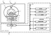
図1は、本実施形態において合成処理を施すための画像を得るためのX線CT装置の全体構成を示した構成図である。 FIG. 1 is a configuration diagram showing the overall configuration of an X-ray CT apparatus for obtaining an image for performing synthesis processing in the present embodiment.
図1において画像診断装置10とは、例えばX線CT装置やMRI装置である。ここではX線CT装置を例に挙げる。X線CT装置はガントリ11を備え、このガントリ11内には回転リング12が設けられ、回転機構(図示なし)によって回転する。回転リング12内にはX線管13とX線検出器14が対向して配置されており、回転リング12の中心部は開口し、そこに寝台に備わる天板15に載置された被検体Pが挿入される。 In FIG. 1, the
X線管13から曝射されたX線は被検体Pを透過し、減衰してX線検出器14によって検出され、その後電気信号に変換され、データ収集部16にて増幅、デジタルデータに変換され、データ伝送装置17を介して投影データが伝送される。 The X-rays exposed from the X-ray tube 13 pass through the subject P, attenuate and are detected by the
コンピュータシステム20において、まずデータ伝送装置17からのデータが前処理部21に送られる。前処理部21では信号強度の補正や信号欠落の補正等の処理を行い、投影データをバスライン300上に出力する。バスライン300上にはシステム制御部22、キーボード等の操作部23、そしてデータ処理部24及びデータを保存するデータ保存部25並びに再構成処理部26を有する画像処理部31、画像表示部27等が接続される。 In the
システム制御部22はコンピュータシステム20の各部の動作や、ガントリ駆動部(図示なし)及びX線制御部(図示なし)を制御するものであり、データ保存部25は断層画像等のデータを記憶するものであり、再構成処理部26は投影データに基づいて断層画像データを再構成する。データ処理部24はデータ保存部25に保存されたデータを用いて各種データ処理を行う。画像表示部27は医用画像等を表示し、操作部23は医師等の操作者によって操作され、画像処理する上で各種の指示や、被検体Pの状態や検査方法等の情報を入力する。 The system control unit 22 controls the operation of each unit of the
画像診断装置10で撮影され、データ伝送装置17を介して伝送された投影データは、前処理部21で補正され、再構成処理部26で断層像データが再構成され、この再構成された画像に基づく三次元画像データがデータ保存部25に保存される。この三次元画像データを用いて様々な画像データを生成する。 The projection data photographed by the
図2は、本実施形態における画像処理に関する全体構成を示したブロック図である。各要素は図1のものと対応しており、画像の合成処理はデータ処理部24にて行われる。データ処理部24は領域設定部30、比較部32、MIP画像生成部36、加算平均画像生成部37、合成画像生成部38、合成画像保存部39、ウィンドウ条件設定部40を備える。 FIG. 2 is a block diagram showing an overall configuration related to image processing in the present embodiment. Each element corresponds to that in FIG. 1, and the image synthesis process is performed by the
領域設定部30は、操作者が操作することにより、三次元画像データから任意の三次元領域を複数設定し、断層厚(以下、厚み)の条件等を設定する。ここで、領域設定部30において設定する断層像の角度や厚みは、画像を生成するためのレンダリング手法に依存してそれぞれ異なる条件を設定してもよい。また、複数の領域はそれぞれ重畳して設定されてもよい。領域の設定に関する詳細は図3を用いて後述する。 The
MIP画像生成部36は、領域設定部30にて設定されたある領域において、MIP画像を生成する。ここで、MIP画像とは、断層の断面と垂直の方向から見てその直線状の各ボクセルにおける最大の画素値(CTではCT値、MRIでは信号強度)を投影して表示している画像のことである。つまり、厚みが変わるとその直線状の画素数も変わるため、MIP値が変化し得る。 The MIP
加算平均画像生成部37は、領域設定部30にて設定されたある領域において、加算平均画像を生成する。ここで、加算平均画像とは、断層の断面と垂直の方向から見てその直線状の各ボクセルにおける全ての画素値の加算平均値を投影して表示している画像のことである。この場合においても上記と同様に、厚みが変わるとその直線上の画素数も変わるため、加算平均値が変化し得る。 The addition average image generation unit 37 generates an addition average image in a certain region set by the
比較部32は、画素値の比較対象となる、予め設定された閾値と、各領域の単位領域における画素値とを、単位領域毎に比較する。 The comparison unit 32 compares, for each unit region, a preset threshold value to be compared with the pixel value and the pixel value in the unit region of each region.
合成画像生成部38は、各領域で得られたMIP画像及び加算平均画像に基づいた合成画像を生成する。このとき、比較部32における比較結果を用いて合成を行ってもよい。 The composite image generation unit 38 generates a composite image based on the MIP image and the addition average image obtained in each region. At this time, synthesis may be performed using the comparison result in the comparison unit 32.
合成画像保存部39は、合成画像生成部38にて生成された合成画像を保存する。またウィンドウ条件設定部40にてウィンドウ条件が変更された場合、その変更を保存する。 The composite image storage unit 39 stores the composite image generated by the composite image generation unit 38. If the window condition setting unit 40 changes the window condition, the change is saved.
ウィンドウ条件設定部40は、各領域におけるウィンドウ条件をそれぞれ変更する。ウィンドウ条件とは、WW/WL(ウィンドウ幅/ウィンドウレベル)値 のことである。 The window condition setting unit 40 changes the window condition in each area. The window condition is a WW / WL (window width / window level) value.
WW/WL値とは、MIP画像や加算平均画像のように濃淡で表現される画像において、表示の明るさとコントラストを調整するためのパラメータである。例えば、CT値が16bit(65536階調)で与えられているときに、その内の特に診断に必要な範囲を切り出して8bit(256階調)に変換することをWW/WL変換といい、このときの切り出し範囲の幅をWW、切り出し範囲の中心値をWLという。 The WW / WL value is a parameter for adjusting the brightness and contrast of display in an image expressed in shades such as an MIP image and an addition average image. For example, when a CT value is given in 16 bits (65536 gradations), cutting out a range particularly necessary for diagnosis and converting it to 8 bits (256 gradations) is called WW / WL conversion. The width of the cutout range at that time is called WW, and the center value of the cutout range is called WL.
厚みとは、三次元画像データからある領域を切り出した断層像における厚みのことをいう。例えば蛇行する血管を観察するにあたり、厚みをもたせて厚み分の情報を投影することで、血管の走行具合を確認することができる。ちなみに厚みを1画素分とすると当然画素値は一つしか存在しないため、そこから生成したMIP画像及び加算平均画像はそれぞれ同様の画像となる。 The thickness means a thickness in a tomographic image obtained by cutting out a certain region from the three-dimensional image data. For example, when observing a meandering blood vessel, it is possible to confirm the running condition of the blood vessel by projecting information corresponding to the thickness with a thickness. Incidentally, since there is naturally only one pixel value when the thickness is one pixel, the MIP image and the addition average image generated from the pixel values are similar to each other.
(領域設定 & MIP画像・加算平均画像生成)
ここで、三次元画像データにおいて領域を複数設定し、領域毎にMIP画像若しくは加算平均画像を生成することに関して説明する。ここでは2つの領域(領域A、領域B)を設定する例を示す。2つではなくとも、操作者は必要に応じて2つ以上の領域を設定してもよい。領域を3つ設定する例は図8を用いて後述する。(Region setting & MIP image / additional average image generation)
Here, a description will be given of setting a plurality of regions in the three-dimensional image data and generating an MIP image or an addition average image for each region. Here, an example in which two areas (area A and area B) are set is shown. Even if the number is not two, the operator may set two or more areas as necessary. An example of setting three areas will be described later with reference to FIG.
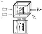
図3(a)は、三次元画像データの斜視図である。 FIG. 3A is a perspective view of 3D image data.
図3(b)は、図3(a)においてY方向から見たときの投影図である。以下、図3におけるZ方向を領域の厚み、X-Y平面を領域の範囲として表現する。 FIG. 3B is a projection when viewed from the Y direction in FIG. Hereinafter, the Z direction in FIG. 3 is expressed as the thickness of the region, and the XY plane is expressed as the region range.
操作者による操作部23の操作に起因し、領域設定部30は、図3(a)、図3(b)に示すように、三次元画像データ内において領域を複数設定する。(領域A、領域B)そしてMIP画像生成部36若しくは加算平均画像生成部37は、領域に応じてそれぞれの画像を生成する。図3(a)、図3(b)においては、領域Bに血管100、そして領域Aに背骨200が入るように各々の領域が設定されている。 Due to the operation of the operation unit 23 by the operator, the
MIP画像を生成する場合は、MIP画像生成部36がMIP画像を生成する。加算平均画像を生成する場合は、加算平均画像生成部37が加算平均画像を生成する。このときの領域は、任意のタイミングで操作者によって変更されてもよい。例えば初めに設定された領域によって得られた画像が最適ではない場合、操作者は、操作部23を操作することにより、最適な画像を求めて領域を設定しなおしてもよい。なお、各々の領域は、必ずしも図3に示すような直方体をしている必要はない。操作者は、操作者の意図に応じて、三次元画像データ内における如何なる範囲の領域を設定してもよい。例えば操作者は、マウス等の操作部23を用いて、図3(c)の領域Bのように任意の領域を設定してもよいし、連結領域抽出等の手法を用いて領域を設定してもよい。 When generating an MIP image, the MIP
ここで、領域の設定に関して説明する。 Here, setting of the area will be described.
(領域の設定&変更方法)
操作者は、画像表示部27に表示された図4に示すような図を確認し、操作部23を操作することによって例えばカーソル35を用いて領域を設定する。(How to set and change area)
The operator confirms the diagram as shown in FIG. 4 displayed on the image display unit 27 and operates the operation unit 23 to set an area using the
操作者は、図4(a)のような三次元画像データの斜視図を確認して三次元領域の範囲を設定し、図4(b)のような投影図を確認して三次元領域の厚みを設定する。このとき、投影図でなくても、ある断面における断面像を確認して三次元領域の範囲及び厚みを設定してもよい。 The operator confirms the perspective view of the three-dimensional image data as shown in FIG. 4A to set the range of the three-dimensional region, and confirms the projection diagram as shown in FIG. Set the thickness. At this time, the range and thickness of the three-dimensional region may be set by confirming a cross-sectional image in a certain cross-section instead of the projection view.
なお、図3(b)、図3(c)、図4(b)に示す投影像は、背骨200の長手方向に対して実質的に垂直となるような、Y軸方向に投影したときの投影像(サジタル画像)である。また、図3(b)、図3(c)、図4(b)に示す図として断面像を用いる場合は、背骨200が断面像に表れるような断面における断面像を画像表示部27に表示させる。 The projection images shown in FIGS. 3B, 3C, and 4B are projected in the Y-axis direction so as to be substantially perpendicular to the longitudinal direction of the
次に、領域を設定しないで得られるMIP画像に関して説明する。 Next, an MIP image obtained without setting an area will be described.
(領域を設定しないで得られるMIP画像)
図5(a)は、領域を設定せず、図3(a)の三次元画像データにおいて、Z方向に投影したMIP画像の一例である。(MIP image obtained without setting area)
FIG. 5A is an example of an MIP image projected in the Z direction in the three-dimensional image data of FIG. 3A without setting an area.
図5(a)は血管100及び背骨200が似たような画素値で重畳して表示されており、共に画素値が高いため血管100と背骨200の境界部分がはっきりしない画像である。これは、MIP画像ではなく加算平均画像を生成しても同様である。 FIG. 5A is an image in which the
次に、領域を設定して得られる合成画像に関して説明する。 Next, a composite image obtained by setting a region will be described.
(領域を設定して得られる合成画像)
一方で図5(b)は、背骨200が含まれている領域である領域Aにおいて、加算平均画像を取得している。その為、領域BにおいてはMIP値ではなく、領域Bの厚み内の画素値をもとにした加算平均値が画素値となる。故に、背骨200の部分は画素値が抑えられ、合成画像生成部38は、図5(b)のように血管100と区別がつきやすくなる合成画像を生成する。(Composite image obtained by setting the area)
On the other hand, in FIG. 5B, the addition average image is acquired in the region A that is the region including the
次に、合成画像の生成に関して説明する。 Next, generation of a composite image will be described.
(合成画像の生成)
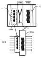
図6は、領域毎に得られたMIP画像若しくは加算平均画像を用い、合成画像を生成する例を示した概略図である。(Generate composite image)
FIG. 6 is a schematic diagram illustrating an example in which a composite image is generated using an MIP image or an addition average image obtained for each region.
MIP画像用の領域B、加算平均画像用の領域Aがそれぞれ1つずつ設定されている例を説明する。 An example will be described in which one region B for MIP images and one region A for addition average images are set.
2枚の画像(MIP画像及び加算平均画像)を用いて、合成画像生成部38が1枚の合成画像を生成するにあたり、比較部32は、予め設定された閾値と、MIP画像における各ピクセルの画素値とを比較する。そして合成画像生成部38は、比較部32の比較結果をもとに、合成画像における各ピクセルの画素値を決定する。MIP画像において閾値よりも高い画素値を有するピクセルにおいては、その画素値にて決定する。そしてMIP画像において閾値よりも低い画素値であるピクセルにおいては、加算平均画像における同一位置のピクセルの画素値を、合成画像における同一位置のピクセルの画素値として決定する。これにより、MIP画像からは画素値の高い血管部分が抽出でき、加算平均画像からはその他の骨等の部分が淡く抽出できる。背骨200及び血管100は共にMIP値が高いが、領域Bにおいては背骨200が領域内に入っていないため、血管100が好適に抽出できる。一方で領域Aにおいては背骨200が領域内に入っているが、領域Aでは加算平均画像を生成しているため、周りの画素値に引きつられ、背骨200の部分は淡く写し出される。 When the composite image generation unit 38 generates one composite image using the two images (MIP image and addition average image), the comparison unit 32 determines a preset threshold value and each pixel in the MIP image. Compare the pixel value. Then, the composite image generation unit 38 determines the pixel value of each pixel in the composite image based on the comparison result of the comparison unit 32. In a pixel having a pixel value higher than the threshold in the MIP image, the pixel value is determined. And in the pixel whose pixel value is lower than the threshold value in the MIP image, the pixel value of the pixel at the same position in the addition average image is determined as the pixel value of the pixel at the same position in the composite image. Thereby, a blood vessel part having a high pixel value can be extracted from the MIP image, and other parts such as bones can be extracted lightly from the addition average image. Both the
図6は、(X6,Y4)及び(X4,Y6)の位置にあるピクセルの画素値と、閾値とを比較する例を示している。 FIG. 6 shows an example in which the pixel values of the pixels at the positions (X6, Y4) and (X4, Y6) are compared with the threshold value.
(X6,Y4)
閾値よりもMIP画像の画素値が大きい例を示している。合成画像の(X6,Y4)の画素値は、MIP画像の(X6,Y4)における画素値と実質的に同様である。(X6, Y4)
An example in which the pixel value of the MIP image is larger than the threshold value is shown. The pixel value of (X6, Y4) in the composite image is substantially the same as the pixel value in (X6, Y4) of the MIP image.
(X4,Y6)
閾値よりもMIP画像の画素値が小さい例を示している。合成画像の(X4,Y6)の画素値は、加算平均画像の(X4,Y6)における画素値と実質的に同様である。(X4, Y6)
An example in which the pixel value of the MIP image is smaller than the threshold value is shown. The pixel value of (X4, Y6) in the composite image is substantially the same as the pixel value in (X4, Y6) of the addition average image.
なお、画素値の決定はピクセル毎に行わず、複数のピクセルによって形成されたクラスタを単位領域とし、その単位領域毎に行ってもよい。 Note that the pixel value is not determined for each pixel, and a cluster formed by a plurality of pixels may be used as a unit region and may be performed for each unit region.
図7は本実施形態のフローチャートである。 FIG. 7 is a flowchart of this embodiment.
(ステップS1)
領域設定部30は、X線CT装置にて得られ、データ保存部25に保存された複数のボクセルからなる三次元画像データにおいて切り出す断層や厚みを設定する。ここで、切り出す断層の角度は各領域で同一のものである必要はない。操作者は、操作部23を操作することにより、図3に示すように、MIP画像用の領域として血管100を包含するような領域(領域B)を設定し、その他の部分を加算平均画像用の領域(領域A)として設定する。各々の領域の厚みは異なっていてもよい。また、各々の領域は重畳する部分が存在していてもよい。領域の設定は、例えば操作者は図3のような表示を画像表示部27にて確認しつつ、マウス等のポインティングデバイスを用いることによって行う。(Step S1)
The
(ステップS2)
MIP画像生成部36は、ステップS1において設定された領域AにおけるMIP画像を生成する。(Step S2)
The MIP
一方、加算平均画像生成部37は、ステップS1において設定された領域Bにおける加算平均画像を生成する。 On the other hand, the addition average image generation unit 37 generates an addition average image in the region B set in step S1.
(ステップS3)
比較部32は、ステップS2にて得られたMIP画像の各々の単位領域における画素値と、予め設定しておいた閾値とを比較する。MIP画像の各々の単位領域における画素値が閾値より高い場合はステップS4Aへと移る。MIP画像の各々の単位領域における画素値が閾値より低い場合はステップS4Bへと移る。(Step S3)
The comparison unit 32 compares the pixel value in each unit region of the MIP image obtained in step S2 with a preset threshold value. When the pixel value in each unit region of the MIP image is higher than the threshold value, the process proceeds to step S4A. When the pixel value in each unit region of the MIP image is lower than the threshold value, the process proceeds to step S4B.
(ステップS4A)
合成画像生成部38は、ステップS3における比較部32の比較結果に基づいて、MIP画像における単位領域の画素値を、該単位領域の画素値として決定する。(Step S4A)
The composite image generation unit 38 determines the pixel value of the unit region in the MIP image as the pixel value of the unit region based on the comparison result of the comparison unit 32 in step S3.
(ステップS4B)
合成画像生成部38は、ステップS3における比較部32の比較結果に基づいて、加算平均画像における単位領域の画素値を、該単位領域の画素値として決定する。(Step S4B)
The composite image generation unit 38 determines the pixel value of the unit area in the addition average image as the pixel value of the unit area based on the comparison result of the comparison unit 32 in step S3.
(ステップS5)
比較部32が比較を行っていない単位領域が存在する場合はステップS3へと移る。比較部32が全ての単位領域において比較を行っている場合は、合成画像生成部38は合成画像を生成し、ステップS6へと移る。(Step S5)
If there is a unit region that the comparison unit 32 does not compare, the process proceeds to step S3. When the comparison unit 32 performs comparison in all unit regions, the composite image generation unit 38 generates a composite image and proceeds to step S6.
(ステップS6)
合成画像保存部39は、ステップS5において生成された合成画像を保存する。また、合成画像保存部39は、ステップS2で得られたMIP画像及び加算平均画像における単位領域毎の画素値の情報を保存する。(Step S6)
The composite image storage unit 39 stores the composite image generated in step S5. The composite image storage unit 39 stores information on pixel values for each unit area in the MIP image and the addition average image obtained in step S2.
(ステップS7)
画像表示部27は、ステップS5において生成された合成画像、若しくはステップS6において保存された合成画像を表示する。(Step S7)
The image display unit 27 displays the composite image generated in step S5 or the composite image stored in step S6.
(ステップS8)
操作者は、画像表示部27に表示された画像を確認し、必要に応じて各条件を変更する。各条件とは、各々の領域の角度、各々の領域の厚み、各々の領域の範囲、各々の領域のウィンドウ条件等である。領域の各条件を変更する場合はステップS2へと移る。厚みを変化させると閾値と比較するための画素値の範囲も変化するため、再びステップS2へ戻る必要がある。ステップS2では、ステップS8にて変更された厚みをもとに、領域毎に画像を生成する。ステップS2以降は上記と同様である。(Step S8)
The operator confirms the image displayed on the image display unit 27 and changes each condition as necessary. Each condition includes an angle of each region, a thickness of each region, a range of each region, a window condition of each region, and the like. When changing each condition of an area | region, it moves to step S2. When the thickness is changed, the range of pixel values for comparison with the threshold value also changes, so it is necessary to return to step S2. In step S2, an image is generated for each region based on the thickness changed in step S8. Step S2 and subsequent steps are the same as described above.
ウィンドウ条件を変更する場合はステップS6へと移る。 When the window condition is changed, the process proceeds to step S6.
以上、ステップS3において閾値とMIP画像の画素値を比較し、単位領域毎に画素値を決定する例を示したが、必ずしもこの手順に沿う必要はない。領域毎にMIP画像若しくは加算平均画像を生成しており、例えば図3における領域Bには血管100が包含されているため、領域BのMIP画像における血管100の部分の画素値は高い。故に、合成画像生成部38は、二枚の画像(領域BにおけるMIP画像、及び領域Aにおける加算平均画像)から、加算平均画像を生成してもよい。このとき合成画像生成部38にて生成される加算平均画像は、血管100部分の画素値は領域BにおけるMIP値よりも低い値になるが、背骨200部分よりも高い画素値であるため、図5(b)に示すような、診断に適した画像である。なお、合成画像生成部38は、上記2枚の画像から加算平均画像を生成しなくてもよい。例えば合成画像生成部38は、血管100部分の単位領域においては領域BにおけるMIP画像の画素値を用い、他の単位領域においては領域Aにおける加算平均画像の画素値を用いるなどの方法で、血管100が操作者にとって認識しやすいような合成画像を生成してもよい。 The example in which the threshold value and the pixel value of the MIP image are compared in step S3 and the pixel value is determined for each unit region has been described above, but it is not always necessary to follow this procedure. For example, the region B in FIG. 3 includes the
図8は、本実施形態における他のフローチャートである。 FIG. 8 is another flowchart in the present embodiment.
図7におけるフローチャートと比較して、ステップS3〜ステップS5におけるステップが異なる。 Compared with the flowchart in FIG. 7, the steps in step S3 to step S5 are different.
(ステップS11)(ステップS12)
図7におけるステップS1及びステップS2と同様である。(Step S11) (Step S12)
This is the same as step S1 and step S2 in FIG.
(ステップS13)
合成画像生成部38は、領域毎に生成された画像(MIP画像、加算平均画像)を用い、合成画像を生成する。このとき、合成画像生成部38は、ステップS12で得られたMIP画像及び加算平均画像に基づいた加算平均画像を生成してもよいし、画素値として、加算平均値に限らず、加算値を用いてもよい。その他、合成画像生成部38は、ステップS12で得られたMIP画像における血管100部分が際立つように表示されるような合成画像を生成する。(Step S13)
The composite image generation unit 38 generates a composite image using an image (MIP image, addition average image) generated for each region. At this time, the composite image generation unit 38 may generate an addition average image based on the MIP image and the addition average image obtained in step S12, and the pixel value is not limited to the addition average value, and the addition value is calculated. It may be used. In addition, the composite image generation unit 38 generates a composite image that is displayed so that the
(ステップS14)(ステップS15)
図7におけるステップS7及びステップS8と同様である。(Step S14) (Step S15)
This is the same as step S7 and step S8 in FIG.
本実施形態ではMIP画像及び加算平均画像を用いて例をあげたが、これに限ることはなく他のレンダリング手法を用いた画像においても本実施形態は適用可能である。例えば、造影剤を注入して血管100を撮影する場合には高い画素値となるためにMIP法が適しているが、他の撮影部位によってはMinIP法を用いるのが適していることもある。例えば、膵管を撮像する場合はMinIP法の技術が有効になる。 In the present embodiment, an example is given using the MIP image and the addition average image. However, the present embodiment is not limited to this, and the present embodiment can be applied to an image using another rendering method. For example, when the
次に、領域を3つ設定し、複数の領域を結合して二次元画像データを得る例を説明する。 Next, an example will be described in which three regions are set and a plurality of regions are combined to obtain two-dimensional image data.
(領域結合)
前述のとおり、領域は3つ設定してもよい。ここでは背骨200に加え、肋骨400をランドマークとして表示させる場合を説明する。(Area join)
As described above, three areas may be set. Here, a case where the
図9は、加算平均法によって加算平均画像を得るための領域A、MIP法によってMIP画像を得るための領域Bに加え、領域Cを設定する例を示した概略図である。領域Cの領域内には肋骨400が含まれる。そして加算平均画像を生成するにあたり、領域Aと領域Cが結合された領域ACを用いる。そして図9に示す投影線に基づいて加算平均画像を生成すると、図10(a)のような背骨200に加えて肋骨400が写し出される画像が得られる。 FIG. 9 is a schematic diagram illustrating an example in which a region C is set in addition to a region A for obtaining an addition average image by the addition average method and a region B for obtaining an MIP image by the MIP method. The
図10(b)は、領域B内におけるMIP画像、及び領域AC内における加算平均画像を用いて生成した合成画像である。図5(b)ではランドマークとして背骨200のみであるが、領域を3つ設定することにより、図10(b)に示すとおり、肋骨400もランドマークとして表示される。 FIG. 10B is a composite image generated using the MIP image in the region B and the addition average image in the region AC. In FIG. 5B, only the
次に、合成画像において、MIP画像若しくは加算平均画像の画素値の計測に関する説明を行う。 Next, description will be made regarding measurement of pixel values of a MIP image or an addition average image in a composite image.
(画素値計測)
操作者が画像表示部27にて合成画像の確認を行うとき、合成前のMIP画像若しくは加算平均画像の画素値も確認できるようにする。例えば操作者は、操作部23を用いて合成画像上にてある領域を指定する。すると画像表示部27は、該領域の、合成前のMIP画像若しくは加算平均画像の画素値を表示する。このときの合成前のMIP画像若しくは加算平均画像の画素値の情報は、合成画像生成部38が画像を合成する際に、合成画像保存部39にて保存しておく。操作者は、合成画像上にて、合成される前の各領域における各画像の画素値を確認することにより、適切な診断を行うことができる。(Pixel value measurement)
When the operator confirms the composite image on the image display unit 27, the pixel value of the MIP image or the addition average image before composition can be confirmed. For example, the operator designates a certain area on the composite image using the operation unit 23. Then, the image display unit 27 displays the pixel value of the MIP image before the synthesis or the addition average image in the area. Information on the pixel values of the MIP image before the synthesis or the addition average image at this time is stored in the composite image storage unit 39 when the composite image generation unit 38 combines the images. The operator can make an appropriate diagnosis by confirming the pixel value of each image in each region before being synthesized on the synthesized image.
次に、本実施形態に係る医用画像処理装置の効果を説明する。 Next, effects of the medical image processing apparatus according to the present embodiment will be described.
以上説明した通り、本実施形態による医用画像処理装置を用いることによって、手術時にランドマークとなる背骨や肋骨を、血管と共に好適に表示させることができる。故に操作者は、血管を満足に観察できる診断画像を得ることができる。それらは三次元画像データにおいて複数の領域を設定し、各々の領域において異なるレンダリング手法による複数枚の画像を生成し、それら画像を用いて合成処理することで実現している。また、合成した画像はMIP画像又は加算平均画像毎に厚みやWW/WLの調整が可能であるため、診断者は診断に合わせて、領域毎にコントラストの良い状態で認識し、所望の観察を行うことができる。これにより、診断者は一枚の画像上において、所望の部位を所望の画質にて観察することができる。 As described above, by using the medical image processing apparatus according to the present embodiment, the spine and ribs that become landmarks at the time of surgery can be suitably displayed together with blood vessels. Therefore, the operator can obtain a diagnostic image that allows a blood vessel to be observed satisfactorily. These are realized by setting a plurality of regions in the three-dimensional image data, generating a plurality of images by different rendering methods in each region, and performing synthesis processing using these images. In addition, since the synthesized image can be adjusted in thickness and WW / WL for each MIP image or addition average image, the diagnostician recognizes in a state with good contrast for each region according to the diagnosis, and performs a desired observation. It can be carried out. Thereby, the diagnostician can observe a desired part with a desired image quality on one image.
一実施形態を説明したが、本実施形態は、例として提示したものであり、発明の範囲を限定することは意図していない。本実施形態は、その他の様々な形態で実施されることが可能であり、発明の要旨を逸脱しない範囲で、種々の省略、置き換え、変更を行うことができる。これら実施形態やその変形は、発明の範囲や要旨に含まれると同様に、特許請求の範囲に記載された発明とその均等の範囲に含まれるものである。 Although one embodiment has been described, this embodiment is presented as an example and is not intended to limit the scope of the invention. The present embodiment can be implemented in various other forms, and various omissions, replacements, and changes can be made without departing from the spirit of the invention. These embodiments and their modifications are included in the scope and gist of the invention, and are also included in the invention described in the claims and the equivalents thereof.
30 領域設定部
31 画像処理部
36 MIP画像生成部
37 加算平均画像生成部
38 合成画像生成部30
Claims (13)
Translated fromJapanese前記複数の三次元領域のそれぞれの領域毎に異なるレンダリング手法を用いて二次元画像データを生成する画像生成部と、
前記複数の三次元領域毎に得られた前記二次元画像データに基づいて合成画像を生成する合成画像生成部と、
前記合成画像を表示する表示部と、
を有する医用画像処理装置。A three-dimensional region setting unit for setting a plurality of different three-dimensional regions;
An image generation unit that generates two-dimensional image data using a different rendering method for each of the plurality of three-dimensional regions;
A composite image generating unit that generates a composite image based on the two-dimensional image data obtained for each of the plurality of three-dimensional regions;
A display unit for displaying the composite image;
A medical image processing apparatus.
前記複数の三次元領域のうち、前記加算平均法によって二次元画像データを得るための三次元領域内には前記被検体の骨を含む請求項5に記載の医用画像処理装置。Among the plurality of three-dimensional regions, the three-dimensional region for obtaining two-dimensional image data by the MIP method includes a blood vessel of the subject.
The medical image processing apparatus according to claim 5, wherein a bone of the subject is included in a three-dimensional region for obtaining two-dimensional image data by the averaging method among the plurality of three-dimensional regions.
前記合成画像が操作されることによって前記情報を表示部に表示する請求項1乃至8いずれかに記載の医用画像処理装置。The composite image includes pixel value information for each unit region of the two-dimensional image,
The medical image processing apparatus according to claim 1, wherein the information is displayed on a display unit when the composite image is operated.
前記三次元領域においてMIP法を用いて第1の二次元画像データを生成し、前記三次元領域以外の領域においてMIP法以外のレンダリング手法を用いて第2の二次元画像データを生成する画像生成部と、
前記第1の二次元画像データ及び前記第2の二次元画像データに基づいて合成画像を生成する合成画像生成部と、
を有する医用画像処理装置。A three-dimensional region setting unit for setting a three-dimensional region so as to include the blood vessel of the subject;
Image generation for generating first two-dimensional image data using the MIP method in the three-dimensional region and generating second two-dimensional image data using a rendering method other than the MIP method in a region other than the three-dimensional region And
A composite image generation unit that generates a composite image based on the first two-dimensional image data and the second two-dimensional image data;
A medical image processing apparatus.
互いに異なる複数の三次元領域を設定させるステップと、
前記複数の三次元領域のそれぞれの領域毎に、全ての前記三次元領域において同一のレンダリング手法を用いることのないように二次元画像データを生成させるステップと、
前記複数の三次元領域毎に得られた前記二次元画像データに基づいて合成画像を生成させるステップと、
を有する医用画像処理方法。In medical image processing device,
Setting a plurality of different three-dimensional regions from each other;
Generating two-dimensional image data for each of the plurality of three-dimensional regions so as not to use the same rendering technique in all the three-dimensional regions;
Generating a composite image based on the two-dimensional image data obtained for each of the plurality of three-dimensional regions;
A medical image processing method.
互いに異なる複数の三次元領域を設定させ、
前記複数の三次元領域のそれぞれの領域毎に、全ての前記三次元領域において同一のレンダリング手法を用いることのないように二次元画像データを生成させ、
前記複数の三次元領域毎に得られた前記二次元画像データに基づいて合成画像を生成させる制御プログラム。In medical image processing device,
Set multiple different 3D regions,
For each of the plurality of three-dimensional regions, two-dimensional image data is generated so as not to use the same rendering method in all the three-dimensional regions,
A control program for generating a composite image based on the two-dimensional image data obtained for each of the plurality of three-dimensional regions.
Priority Applications (1)
| Application Number | Priority Date | Filing Date | Title |
|---|---|---|---|
| JP2012120115AJP2013244211A (en) | 2012-05-25 | 2012-05-25 | Medical image processor, medical image processing method and control program |
Applications Claiming Priority (1)
| Application Number | Priority Date | Filing Date | Title |
|---|---|---|---|
| JP2012120115AJP2013244211A (en) | 2012-05-25 | 2012-05-25 | Medical image processor, medical image processing method and control program |
Publications (1)
| Publication Number | Publication Date |
|---|---|
| JP2013244211Atrue JP2013244211A (en) | 2013-12-09 |
Family
ID=49844469
Family Applications (1)
| Application Number | Title | Priority Date | Filing Date |
|---|---|---|---|
| JP2012120115APendingJP2013244211A (en) | 2012-05-25 | 2012-05-25 | Medical image processor, medical image processing method and control program |
Country Status (1)
| Country | Link |
|---|---|
| JP (1) | JP2013244211A (en) |
Cited By (18)
| Publication number | Priority date | Publication date | Assignee | Title |
|---|---|---|---|---|
| JP2017510323A (en)* | 2014-02-28 | 2017-04-13 | ホロジック, インコーポレイテッドHologic, Inc. | System and method for generating and displaying tomosynthesis image slabs |
| JP2022526964A (en)* | 2019-04-02 | 2022-05-27 | コーニンクレッカ フィリップス エヌ ヴェ | Automated system for rapid detection and indexing of critical areas in non-contrast head CT |
| US11403483B2 (en) | 2017-06-20 | 2022-08-02 | Hologic, Inc. | Dynamic self-learning medical image method and system |
| US11406332B2 (en) | 2011-03-08 | 2022-08-09 | Hologic, Inc. | System and method for dual energy and/or contrast enhanced breast imaging for screening, diagnosis and biopsy |
| US11445993B2 (en) | 2017-03-30 | 2022-09-20 | Hologic, Inc. | System and method for targeted object enhancement to generate synthetic breast tissue images |
| US11452486B2 (en) | 2006-02-15 | 2022-09-27 | Hologic, Inc. | Breast biopsy and needle localization using tomosynthesis systems |
| US11455754B2 (en) | 2017-03-30 | 2022-09-27 | Hologic, Inc. | System and method for synthesizing low-dimensional image data from high-dimensional image data using an object grid enhancement |
| US11508340B2 (en) | 2011-11-27 | 2022-11-22 | Hologic, Inc. | System and method for generating a 2D image using mammography and/or tomosynthesis image data |
| US11589944B2 (en) | 2013-03-15 | 2023-02-28 | Hologic, Inc. | Tomosynthesis-guided biopsy apparatus and method |
| US11663780B2 (en) | 2012-02-13 | 2023-05-30 | Hologic Inc. | System and method for navigating a tomosynthesis stack using synthesized image data |
| US11701199B2 (en) | 2009-10-08 | 2023-07-18 | Hologic, Inc. | Needle breast biopsy system and method of use |
| US11775156B2 (en) | 2010-11-26 | 2023-10-03 | Hologic, Inc. | User interface for medical image review workstation |
| US11957497B2 (en) | 2017-03-30 | 2024-04-16 | Hologic, Inc | System and method for hierarchical multi-level feature image synthesis and representation |
| US12029602B2 (en) | 2013-10-24 | 2024-07-09 | Hologic, Inc. | System and method for navigating x-ray guided breast biopsy |
| US12211608B2 (en) | 2013-03-15 | 2025-01-28 | Hologic, Inc. | System and method for navigating a tomosynthesis stack including automatic focusing |
| US12236582B2 (en) | 2018-09-24 | 2025-02-25 | Hologic, Inc. | Breast mapping and abnormality localization |
| US12236597B2 (en) | 2021-11-29 | 2025-02-25 | Hologic, Inc. | Systems and methods for correlating objects of interest |
| US12254586B2 (en) | 2021-10-25 | 2025-03-18 | Hologic, Inc. | Auto-focus tool for multimodality image review |
Citations (4)
| Publication number | Priority date | Publication date | Assignee | Title |
|---|---|---|---|---|
| JPH0973557A (en)* | 1995-09-04 | 1997-03-18 | Toshiba Corp | Image processing device |
| US20060050963A1 (en)* | 2004-09-06 | 2006-03-09 | Kabushiki Kaisha Toshiba | Image data area extracting system and image data area extracting method |
| JP2007034518A (en)* | 2005-07-25 | 2007-02-08 | Toshiba Corp | Medical image processing apparatus and medical image processing method |
| JP2009006086A (en)* | 2007-06-29 | 2009-01-15 | Ziosoft Inc | Image processing method, image processing program, and image processing apparatus |
- 2012
- 2012-05-25JPJP2012120115Apatent/JP2013244211A/enactivePending
Patent Citations (4)
| Publication number | Priority date | Publication date | Assignee | Title |
|---|---|---|---|---|
| JPH0973557A (en)* | 1995-09-04 | 1997-03-18 | Toshiba Corp | Image processing device |
| US20060050963A1 (en)* | 2004-09-06 | 2006-03-09 | Kabushiki Kaisha Toshiba | Image data area extracting system and image data area extracting method |
| JP2007034518A (en)* | 2005-07-25 | 2007-02-08 | Toshiba Corp | Medical image processing apparatus and medical image processing method |
| JP2009006086A (en)* | 2007-06-29 | 2009-01-15 | Ziosoft Inc | Image processing method, image processing program, and image processing apparatus |
Cited By (34)
| Publication number | Priority date | Publication date | Assignee | Title |
|---|---|---|---|---|
| US12193853B2 (en) | 2006-02-15 | 2025-01-14 | Hologic, Inc. | Breast biopsy and needle localization using tomosynthesis systems |
| US11452486B2 (en) | 2006-02-15 | 2022-09-27 | Hologic, Inc. | Breast biopsy and needle localization using tomosynthesis systems |
| US11918389B2 (en) | 2006-02-15 | 2024-03-05 | Hologic, Inc. | Breast biopsy and needle localization using tomosynthesis systems |
| US12193886B2 (en) | 2009-10-08 | 2025-01-14 | Hologic, Inc. | Needle breast biopsy system and method of use |
| US11701199B2 (en) | 2009-10-08 | 2023-07-18 | Hologic, Inc. | Needle breast biopsy system and method of use |
| US11775156B2 (en) | 2010-11-26 | 2023-10-03 | Hologic, Inc. | User interface for medical image review workstation |
| US11406332B2 (en) | 2011-03-08 | 2022-08-09 | Hologic, Inc. | System and method for dual energy and/or contrast enhanced breast imaging for screening, diagnosis and biopsy |
| US12239471B2 (en) | 2011-03-08 | 2025-03-04 | Hologic, Inc. | System and method for dual energy and/or contrast enhanced breast imaging for screening, diagnosis and biopsy |
| US11837197B2 (en) | 2011-11-27 | 2023-12-05 | Hologic, Inc. | System and method for generating a 2D image using mammography and/or tomosynthesis image data |
| US12183309B2 (en) | 2011-11-27 | 2024-12-31 | Hologic, Inc. | System and method for generating a 2D image using mammography and/or tomosynthesis image data |
| US11508340B2 (en) | 2011-11-27 | 2022-11-22 | Hologic, Inc. | System and method for generating a 2D image using mammography and/or tomosynthesis image data |
| US12307604B2 (en) | 2012-02-13 | 2025-05-20 | Hologic, Inc. | System and method for navigating a tomosynthesis stack using synthesized image data |
| US11663780B2 (en) | 2012-02-13 | 2023-05-30 | Hologic Inc. | System and method for navigating a tomosynthesis stack using synthesized image data |
| US11589944B2 (en) | 2013-03-15 | 2023-02-28 | Hologic, Inc. | Tomosynthesis-guided biopsy apparatus and method |
| US12324707B2 (en) | 2013-03-15 | 2025-06-10 | Hologic, Inc. | Tomosynthesis-guided biopsy in prone |
| US12211608B2 (en) | 2013-03-15 | 2025-01-28 | Hologic, Inc. | System and method for navigating a tomosynthesis stack including automatic focusing |
| US12064291B2 (en) | 2013-03-15 | 2024-08-20 | Hologic, Inc. | Tomosynthesis-guided biopsy in prone |
| US12029602B2 (en) | 2013-10-24 | 2024-07-09 | Hologic, Inc. | System and method for navigating x-ray guided breast biopsy |
| JP2017510323A (en)* | 2014-02-28 | 2017-04-13 | ホロジック, インコーポレイテッドHologic, Inc. | System and method for generating and displaying tomosynthesis image slabs |
| US11801025B2 (en) | 2014-02-28 | 2023-10-31 | Hologic, Inc. | System and method for generating and displaying tomosynthesis image slabs |
| US11419565B2 (en) | 2014-02-28 | 2022-08-23 | IIologic, Inc. | System and method for generating and displaying tomosynthesis image slabs |
| US11445993B2 (en) | 2017-03-30 | 2022-09-20 | Hologic, Inc. | System and method for targeted object enhancement to generate synthetic breast tissue images |
| US12070349B2 (en) | 2017-03-30 | 2024-08-27 | Hologic, Inc. | System and method for targeted object enhancement to generate synthetic breast tissue images |
| US11455754B2 (en) | 2017-03-30 | 2022-09-27 | Hologic, Inc. | System and method for synthesizing low-dimensional image data from high-dimensional image data using an object grid enhancement |
| US11957497B2 (en) | 2017-03-30 | 2024-04-16 | Hologic, Inc | System and method for hierarchical multi-level feature image synthesis and representation |
| US11983799B2 (en) | 2017-03-30 | 2024-05-14 | Hologic, Inc. | System and method for synthesizing low-dimensional image data from high-dimensional image data using an object grid enhancement |
| US12211124B2 (en) | 2017-03-30 | 2025-01-28 | Hologic, Inc. | System and method for synthesizing low-dimensional image data from high-dimensional image data using an object grid enhancement |
| US11403483B2 (en) | 2017-06-20 | 2022-08-02 | Hologic, Inc. | Dynamic self-learning medical image method and system |
| US11850021B2 (en) | 2017-06-20 | 2023-12-26 | Hologic, Inc. | Dynamic self-learning medical image method and system |
| US12236582B2 (en) | 2018-09-24 | 2025-02-25 | Hologic, Inc. | Breast mapping and abnormality localization |
| JP2022526964A (en)* | 2019-04-02 | 2022-05-27 | コーニンクレッカ フィリップス エヌ ヴェ | Automated system for rapid detection and indexing of critical areas in non-contrast head CT |
| JP7520037B2 (en) | 2019-04-02 | 2024-07-22 | コーニンクレッカ フィリップス エヌ ヴェ | Automated system for rapid detection and indexing of critical regions in non-contrast head CT |
| US12254586B2 (en) | 2021-10-25 | 2025-03-18 | Hologic, Inc. | Auto-focus tool for multimodality image review |
| US12236597B2 (en) | 2021-11-29 | 2025-02-25 | Hologic, Inc. | Systems and methods for correlating objects of interest |
Similar Documents
| Publication | Publication Date | Title |
|---|---|---|
| JP2013244211A (en) | Medical image processor, medical image processing method and control program | |
| JP5400326B2 (en) | Method for displaying tomosynthesis images | |
| US8611989B2 (en) | Multi-planar reconstruction lumen imaging method and apparatus | |
| JP2009095671A (en) | Method and system for visualizing registered image | |
| JP6058286B2 (en) | Medical image diagnostic apparatus, medical image processing apparatus and method | |
| US10537293B2 (en) | X-ray CT system, image display device, and image display method | |
| US10092264B2 (en) | Image processing apparatus, image processing method, radiation imaging system, and non-transitory computer-readable storage medium | |
| JP2009106530A (en) | Medical image processing apparatus, medical image processing method, and medical image diagnostic apparatus | |
| JP4122463B2 (en) | Method for generating medical visible image | |
| JP2005103263A (en) | Method of operating image forming inspection apparatus having tomographic capability and X-ray computed tomography apparatus | |
| JP6738631B2 (en) | Medical image processing apparatus, medical image processing method, and medical image processing program | |
| JP2010154982A (en) | X-ray computer tomographic imaging apparatus and image processor | |
| JP5454841B2 (en) | Medical image processing device | |
| JP4996128B2 (en) | Medical image processing apparatus and medical image processing method | |
| JP5305635B2 (en) | Medical image display device | |
| JP4686279B2 (en) | Medical diagnostic apparatus and diagnostic support apparatus | |
| JP6433190B2 (en) | Image processing apparatus, image processing method, and program | |
| KR101525040B1 (en) | Method and Apparatus of Generation of reference image for determining scan range of pre-operative images | |
| JP4612379B2 (en) | Medical image diagnosis support system, medical image diagnosis support device, medical image diagnosis support method, computer-readable storage medium, and computer program | |
| JP5487339B2 (en) | Medical image processing device | |
| JP6021340B2 (en) | Medical image processing apparatus and control program | |
| JP6957337B2 (en) | Image processing equipment, image processing methods and programs | |
| US20250177043A1 (en) | Systems and methods of dynamic reachability visualization for trajectory planning | |
| JP6433189B2 (en) | Image processing apparatus, image processing method, and program | |
| US20250295455A1 (en) | Support device, support method, and support program |
Legal Events
| Date | Code | Title | Description |
|---|---|---|---|
| RD01 | Notification of change of attorney | Free format text:JAPANESE INTERMEDIATE CODE: A7421 Effective date:20141226 | |
| RD02 | Notification of acceptance of power of attorney | Free format text:JAPANESE INTERMEDIATE CODE: A7422 Effective date:20150216 | |
| RD04 | Notification of resignation of power of attorney | Free format text:JAPANESE INTERMEDIATE CODE: A7424 Effective date:20150218 | |
| A621 | Written request for application examination | Free format text:JAPANESE INTERMEDIATE CODE: A621 Effective date:20150512 | |
| A711 | Notification of change in applicant | Free format text:JAPANESE INTERMEDIATE CODE: A712 Effective date:20150626 | |
| A977 | Report on retrieval | Free format text:JAPANESE INTERMEDIATE CODE: A971007 Effective date:20160217 | |
| A131 | Notification of reasons for refusal | Free format text:JAPANESE INTERMEDIATE CODE: A131 Effective date:20160304 | |
| A711 | Notification of change in applicant | Free format text:JAPANESE INTERMEDIATE CODE: A711 Effective date:20160620 | |
| RD07 | Notification of extinguishment of power of attorney | Free format text:JAPANESE INTERMEDIATE CODE: A7427 Effective date:20160627 | |
| A02 | Decision of refusal | Free format text:JAPANESE INTERMEDIATE CODE: A02 Effective date:20160913 |